Biomechanics of Tooth-Movement: Current Look at...
35
22 Biomechanics of Tooth-Movement: Current Look at Orthodontic Fundamental Joanna Antoszewska 1 and Nazan Küçükkeleş 2 1 Wroclaw Medical University, 2 Marmara University, 1 Poland 2 Turkey 1. Introduction Numerous methods of efficient orthodontic tooth-movement have been described in the literature for over 100 years, since Edward Hartley Angle had introduced foundations of malocclusion treatment (fig. 1). In such long term, different treatment philosophies have been permanently encountering beginning from Tweed 1 and his extraction concept versus Fig. 1. Beginning of former century: philosophy proposed by the father of Orthodontic School, E.H. Angle www.intechopen.com
Transcript of Biomechanics of Tooth-Movement: Current Look at...
22
Biomechanics of Tooth-Movement:
Current Look at Orthodontic Fundamental
Joanna Antoszewska1 and Nazan Küçükkeleş2
1Wroclaw Medical University, 2Marmara University,
1Poland 2Turkey
1. Introduction
Numerous methods of efficient orthodontic tooth-movement have been described in the literature for over 100 years, since Edward Hartley Angle had introduced foundations of malocclusion treatment (fig. 1). In such long term, different treatment philosophies have been permanently encountering beginning from Tweed1 and his extraction concept versus
Fig. 1. Beginning of former century: philosophy proposed by the father of Orthodontic School, E.H. Angle
www.intechopen.com
Principles in Contemporary Orthodontics
494
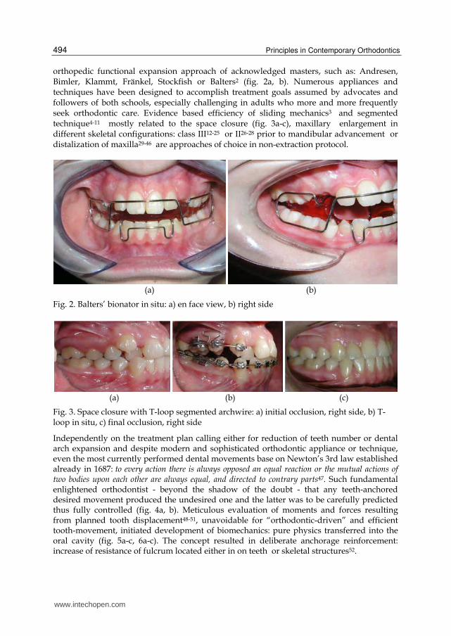
orthopedic functional expansion approach of acknowledged masters, such as: Andresen, Bimler, Klammt, Fränkel, Stockfish or Balters2 (fig. 2a, b). Numerous appliances and techniques have been designed to accomplish treatment goals assumed by advocates and followers of both schools, especially challenging in adults who more and more frequently seek orthodontic care. Evidence based efficiency of sliding mechanics3 and segmented technique4-11 mostly related to the space closure (fig. 3a-c), maxillary enlargement in different skeletal configurations: class III12-25 or II26-28 prior to mandibular advancement or distalization of maxilla29-46 are approaches of choice in non-extraction protocol.
(a) (b)
Fig. 2. Balters’ bionator in situ: a) en face view, b) right side
(a) (b) (c)
Fig. 3. Space closure with T-loop segmented archwire: a) initial occlusion, right side, b) T-loop in situ, c) final occlusion, right side
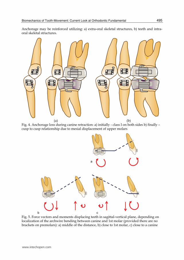
Independently on the treatment plan calling either for reduction of teeth number or dental arch expansion and despite modern and sophisticated orthodontic appliance or technique, even the most currently performed dental movements base on Newton’s 3rd law established already in 1687: to every action there is always opposed an equal reaction or the mutual actions of two bodies upon each other are always equal, and directed to contrary parts47. Such fundamental enlightened orthodontist - beyond the shadow of the doubt - that any teeth-anchored desired movement produced the undesired one and the latter was to be carefully predicted thus fully controlled (fig. 4a, b). Meticulous evaluation of moments and forces resulting from planned tooth displacement48-51, unavoidable for “orthodontic-driven” and efficient tooth-movement, initiated development of biomechanics: pure physics transferred into the oral cavity (fig. 5a-c, 6a-c). The concept resulted in deliberate anchorage reinforcement: increase of resistance of fulcrum located either in on teeth or skeletal structures52.
www.intechopen.com
Biomechanics of Tooth-Movement: Current Look at Orthodontic Fundamental
495
Anchorage may be reinforced utilizing: a) extra-oral skeletal structures, b) teeth and intra-oral skeletal structures.
(a) (b) Fig. 4. Anchorage loss during canine retraction: a) initially - class I on both sides b) finally – cusp to cusp relationship due to mesial displacement of upper molars
Fig. 5. Force vectors and moments displacing teeth in sagittal-vertical plane, depending on localization of the archwire bending between canine and 1st molar (provided there are no brackets on premolars): a) middle of the distance, b) close to 1st molar, c) close to a canine
www.intechopen.com
Principles in Contemporary Orthodontics
496
(a) (b) (c)
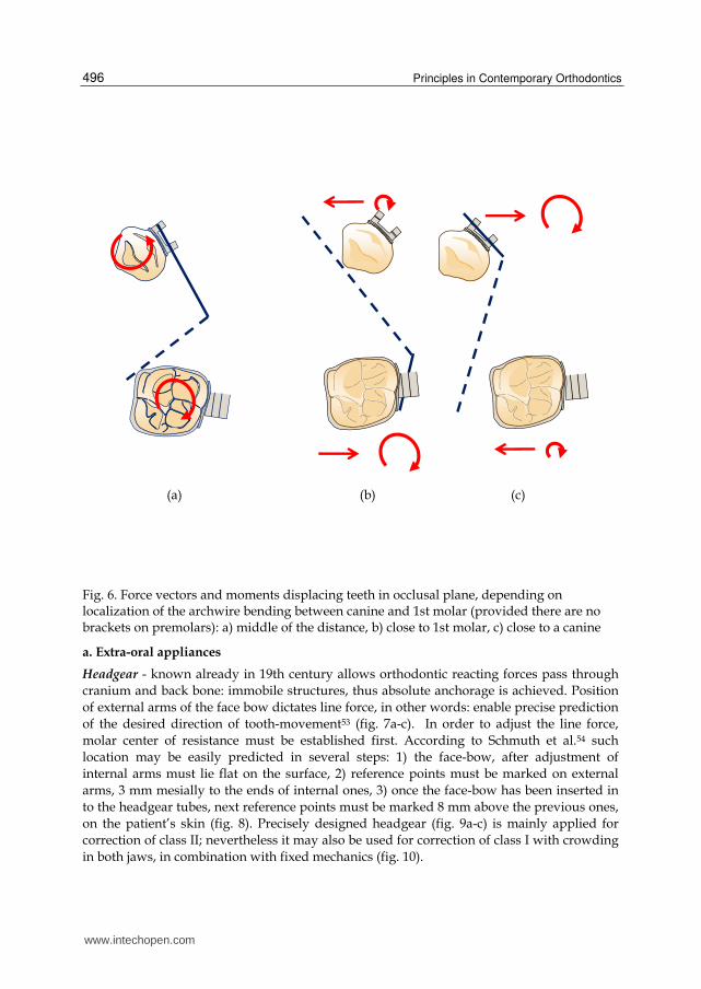
Fig. 6. Force vectors and moments displacing teeth in occlusal plane, depending on localization of the archwire bending between canine and 1st molar (provided there are no brackets on premolars): a) middle of the distance, b) close to 1st molar, c) close to a canine
a. Extra-oral appliances
Headgear - known already in 19th century allows orthodontic reacting forces pass through
cranium and back bone: immobile structures, thus absolute anchorage is achieved. Position
of external arms of the face bow dictates line force, in other words: enable precise prediction
of the desired direction of tooth-movement53 (fig. 7a-c). In order to adjust the line force,
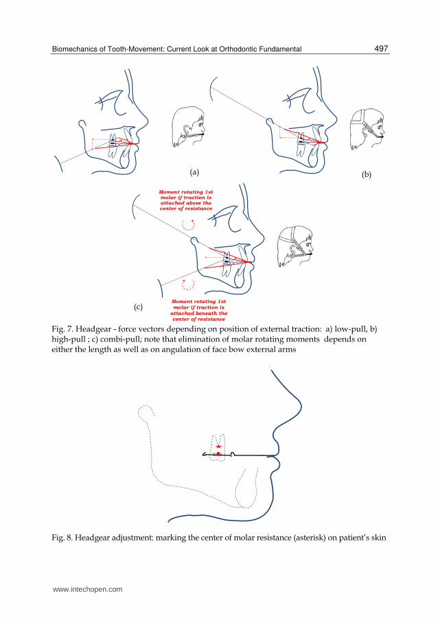
molar center of resistance must be established first. According to Schmuth et al.54 such
location may be easily predicted in several steps: 1) the face-bow, after adjustment of
internal arms must lie flat on the surface, 2) reference points must be marked on external
arms, 3 mm mesially to the ends of internal ones, 3) once the face-bow has been inserted in
to the headgear tubes, next reference points must be marked 8 mm above the previous ones,
on the patient’s skin (fig. 8). Precisely designed headgear (fig. 9a-c) is mainly applied for
correction of class II; nevertheless it may also be used for correction of class I with crowding
in both jaws, in combination with fixed mechanics (fig. 10).
www.intechopen.com
Biomechanics of Tooth-Movement: Current Look at Orthodontic Fundamental
497
Fig. 7. Headgear - force vectors depending on position of external traction: a) low-pull, b) high-pull ; c) combi-pull; note that elimination of molar rotating moments depends on either the length as well as on angulation of face bow external arms
Fig. 8. Headgear adjustment: marking the center of molar resistance (asterisk) on patient’s skin
(a) (b)
(c)
Moment rotating 1st molar if traction is attached above the center of resistance
Moment rotating 1st molar if traction is
attached beneath the center of resistance
www.intechopen.com
Principles in Contemporary Orthodontics
498
(a) (b) (c)
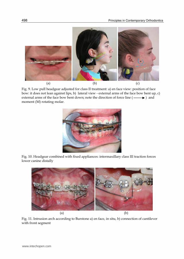
Fig. 9. Low pull headgear adjusted for class II treatment: a) en face view: position of face bow: it does not lean against lips, b) lateral view - external arms of the face bow bent up, c) external arms of the face bow bent down; note the direction of force line ( ) and moment (M) rotating molar.
Fig. 10. Headgear combined with fixed appliances: intermaxillary class III traction forces lower canine distally
(a) (b)
Fig. 11. Intrusion arch according to Burstone a) en face, in situ, b) connection of cantilever with front segment
www.intechopen.com

Biomechanics of Tooth-Movement: Current Look at Orthodontic Fundamental
499
Current mathematic calculations of forces couneracting reactive ones resulting from the front teeth movement are presented by Braun55. Burstone’s intrusion arch (fig. 11a, b) while intruding upper incisors with the 50 g of force, simultaneously extrudes molars with the same force value. To prevent the latter phenomena, high-pull headgear is to be worn 8 hours per day. It is illustrated with the formula: F1 x 8h = 50 g x 24h, where F1 = 150 g is a vertical component of the force produced by high-pull traction (fig. 12). However net force
Fig. 12. Biomechanics of incisor intrusion with Burstone’s cantilever. Source: Joanna Antoszewska (2009) Wykorzystanie tymczasowego zakotwienia kortykalnego w leczeniu zaburzeń zgryzowo-zębowych. Wrocław : Akad. Med., 5; 111 s. (Rozprawy Habilitacyjne Akademii Medycznej we Wrocławiu). ISBN 978-83-7055-489-7
vector is inclined 600 to the occlusal plane, therefore net force value (FH) equals: FH = F1/sin
600 = 173 g. Furthermore, in order to compensate side effect of Burstone’s cantilever -
moment inclining molars distally - stripes of high-pull headgear must be attached at the
certain distance (D) from the center of molar resistance, thus inclining molars mesially: 50 g
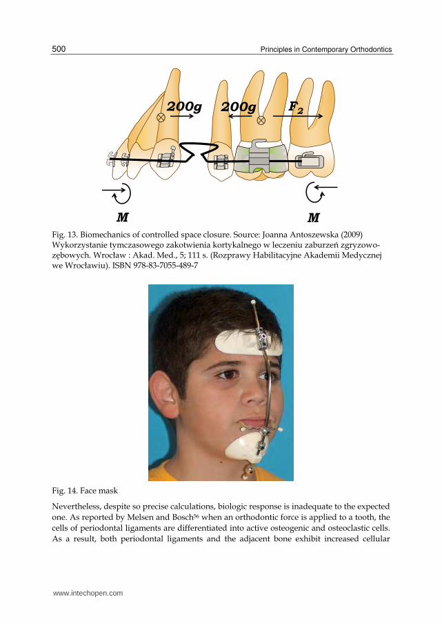
x 24h x 30 = 173 g x 8h x D, so D = 26,01 mm. Another example: retraction of front teeth
with the 200 g of force simultaneously displaces molars mesially (fig. 13). Horizontal force
reinforcing anchorage (F2) and originating from the low-pull headgear worn 10 hours per
day equals 480 g (200 g x 24 h = F2 x 10 h). Consequently, since the net force vectors of either
high-pull as well as low-pull headgears are inclined to the occlusal plane, their efficient
force values equal 627 g (480/cos 400) and 679 g (480 g/cos 450) respectively.
www.intechopen.com
Principles in Contemporary Orthodontics
500
Fig. 13. Biomechanics of controlled space closure. Source: Joanna Antoszewska (2009) Wykorzystanie tymczasowego zakotwienia kortykalnego w leczeniu zaburzeń zgryzowo-zębowych. Wrocław : Akad. Med., 5; 111 s. (Rozprawy Habilitacyjne Akademii Medycznej we Wrocławiu). ISBN 978-83-7055-489-7
Fig. 14. Face mask
Nevertheless, despite so precise calculations, biologic response is inadequate to the expected
one. As reported by Melsen and Bosch56 when an orthodontic force is applied to a tooth, the
cells of periodontal ligaments are differentiated into active osteogenic and osteoclastic cells.
As a result, both periodontal ligaments and the adjacent bone exhibit increased cellular
www.intechopen.com
Biomechanics of Tooth-Movement: Current Look at Orthodontic Fundamental
501
activity facilitating tooth movement, therefore headgear - if worn intermittently - is
incapable of efficient anchorage reinforcement.
Face mask applied in class III treatment as orthodontic and orthopedic traction (fig. 14) is
anchored on a forehead and a chin. Since mandible is a moving structure, therewith its
response is unpredictable in terms of mathematic calculations, although efficient clinically.
Nevertheless, as anchorage control is also achieved intermittently, all the displacements are
resultants of the desired movements and transient collapses.
b. Teeth anchored appliances
Teeth anchored appliances are generally the most popular ones widely used for anchorage
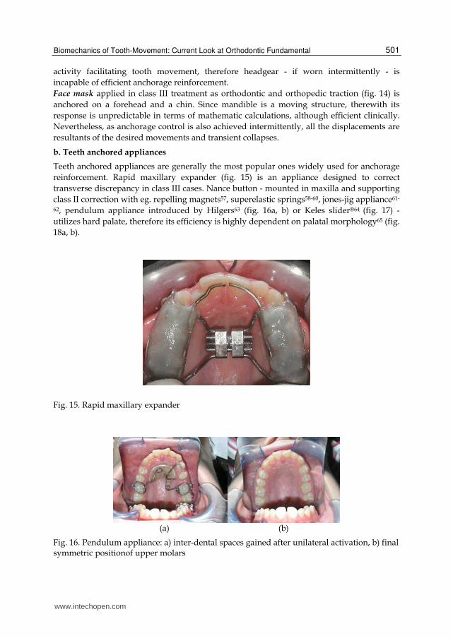
reinforcement. Rapid maxillary expander (fig. 15) is an appliance designed to correct
transverse discrepancy in class III cases. Nance button - mounted in maxilla and supporting
class II correction with eg. repelling magnets57, superelastic springs58-60, jones-jig appliance61-
62, pendulum appliance introduced by Hilgers63 (fig. 16a, b) or Keles slider®64 (fig. 17) -
utilizes hard palate, therefore its efficiency is highly dependent on palatal morphology65 (fig.
18a, b).
Fig. 15. Rapid maxillary expander
(a) (b)
Fig. 16. Pendulum appliance: a) inter-dental spaces gained after unilateral activation, b) final symmetric positionof upper molars
www.intechopen.com
Principles in Contemporary Orthodontics
502
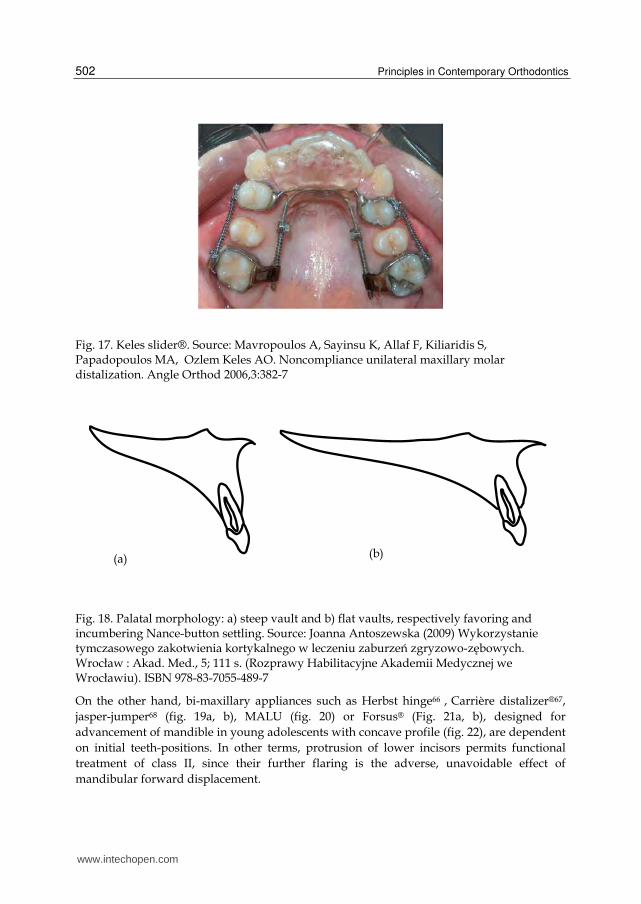
Fig. 17. Keles slider®. Source: Mavropoulos A, Sayinsu K, Allaf F, Kiliaridis S, Papadopoulos MA, Ozlem Keles AO. Noncompliance unilateral maxillary molar distalization. Angle Orthod 2006,3:382-7
Fig. 18. Palatal morphology: a) steep vault and b) flat vaults, respectively favoring and incumbering Nance-button settling. Source: Joanna Antoszewska (2009) Wykorzystanie tymczasowego zakotwienia kortykalnego w leczeniu zaburzeń zgryzowo-zębowych. Wrocław : Akad. Med., 5; 111 s. (Rozprawy Habilitacyjne Akademii Medycznej we Wrocławiu). ISBN 978-83-7055-489-7
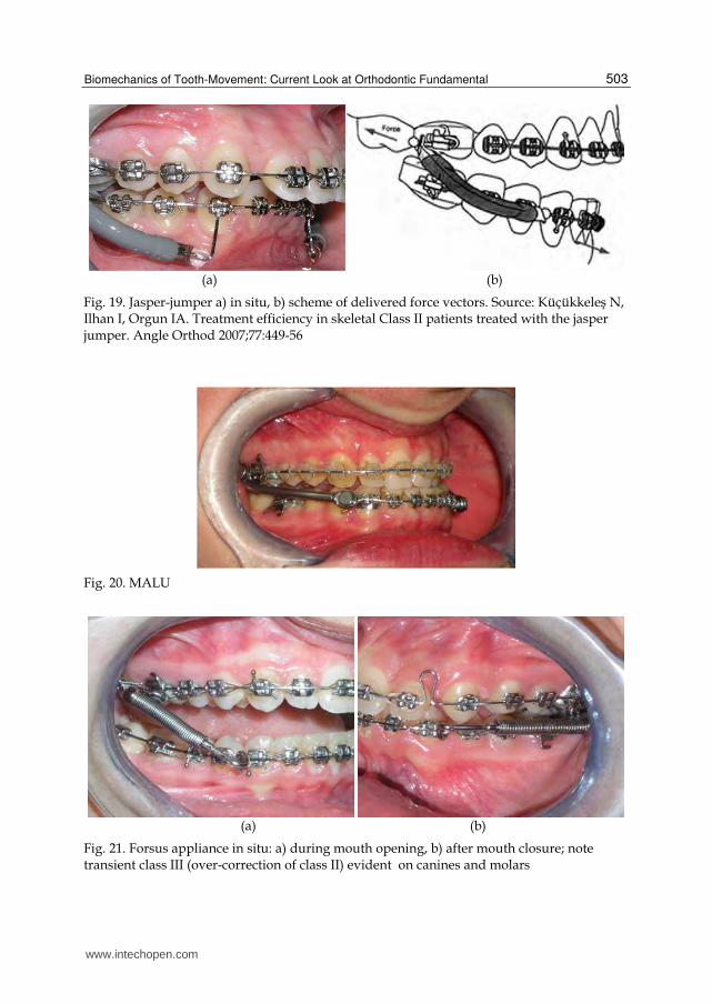
On the other hand, bi-maxillary appliances such as Herbst hinge66 , Carrière distalizer®67,
jasper-jumper68 (fig. 19a, b), MALU (fig. 20) or Forsus® (Fig. 21a, b), designed for
advancement of mandible in young adolescents with concave profile (fig. 22), are dependent
on initial teeth-positions. In other terms, protrusion of lower incisors permits functional
treatment of class II, since their further flaring is the adverse, unavoidable effect of
mandibular forward displacement.
(a) (b)
www.intechopen.com
Biomechanics of Tooth-Movement: Current Look at Orthodontic Fundamental
503
(a) (b)
Fig. 19. Jasper-jumper a) in situ, b) scheme of delivered force vectors. Source: Küçükkeleş N, Ilhan I, Orgun IA. Treatment efficiency in skeletal Class II patients treated with the jasper jumper. Angle Orthod 2007;77:449-56
Fig. 20. MALU
(a) (b)
Fig. 21. Forsus appliance in situ: a) during mouth opening, b) after mouth closure; note transient class III (over-correction of class II) evident on canines and molars
www.intechopen.com
Principles in Contemporary Orthodontics
504
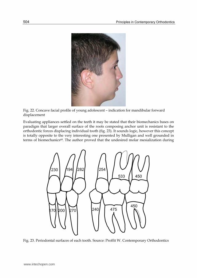
Fig. 22. Concave facial profile of young adolescent – indication for mandibular forward displacement
Evaluating appliances settled on the teeth it may be stated that their biomechanics bases on paradigm that larger overall surface of the roots composing anchor unit is resistant to the orthodontic forces displacing individual tooth (fig. 23). It sounds logic, however this concept is totally opposite to the very interesting one presented by Mulligan and well grounded in terms of biomechanics69. The author proved that the undesired molar mesialization during
Fig. 23. Periodontal surfaces of each tooth. Source: Proffit W. Contemporary Orthodontics
www.intechopen.com
Biomechanics of Tooth-Movement: Current Look at Orthodontic Fundamental
505
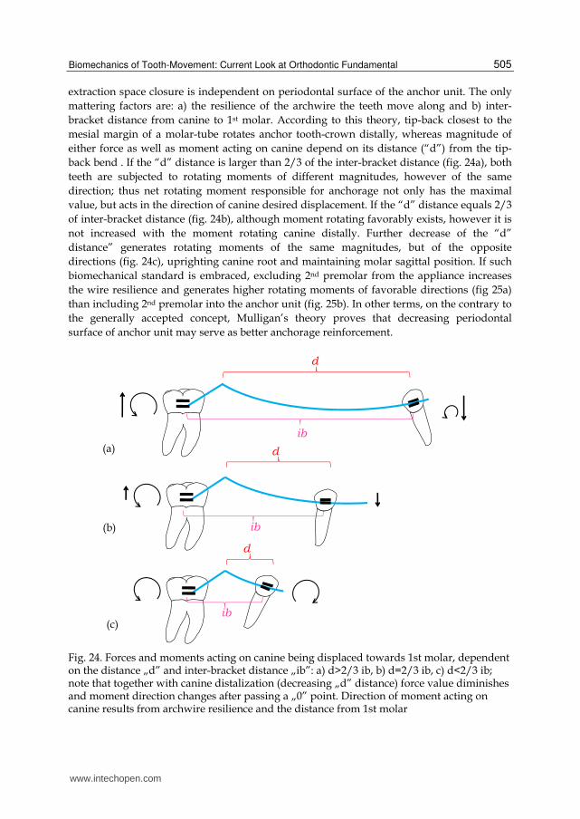
extraction space closure is independent on periodontal surface of the anchor unit. The only
mattering factors are: a) the resilience of the archwire the teeth move along and b) inter-
bracket distance from canine to 1st molar. According to this theory, tip-back closest to the
mesial margin of a molar-tube rotates anchor tooth-crown distally, whereas magnitude of
either force as well as moment acting on canine depend on its distance (“d”) from the tip-
back bend . If the “d” distance is larger than 2/3 of the inter-bracket distance (fig. 24a), both
teeth are subjected to rotating moments of different magnitudes, however of the same
direction; thus net rotating moment responsible for anchorage not only has the maximal
value, but acts in the direction of canine desired displacement. If the “d” distance equals 2/3
of inter-bracket distance (fig. 24b), although moment rotating favorably exists, however it is
not increased with the moment rotating canine distally. Further decrease of the “d”
distance” generates rotating moments of the same magnitudes, but of the opposite
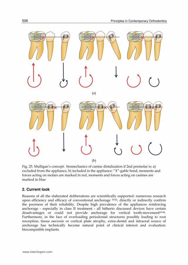
directions (fig. 24c), uprighting canine root and maintaining molar sagittal position. If such
biomechanical standard is embraced, excluding 2nd premolar from the appliance increases
the wire resilience and generates higher rotating moments of favorable directions (fig 25a)
than including 2nd premolar into the anchor unit (fig. 25b). In other terms, on the contrary to
the generally accepted concept, Mulligan’s theory proves that decreasing periodontal
surface of anchor unit may serve as better anchorage reinforcement.
Fig. 24. Forces and moments acting on canine being displaced towards 1st molar, dependent on the distance „d” and inter-bracket distance „ib”: a) d>2/3 ib, b) d=2/3 ib, c) d<2/3 ib; note that together with canine distalization (decreasing „d” distance) force value diminishes and moment direction changes after passing a „0” point. Direction of moment acting on canine results from archwire resilience and the distance from 1st molar
(a)
(b)
(c)
www.intechopen.com
Principles in Contemporary Orthodontics
506
(a)
(b)
Fig. 25. Mulligan’s concept: biomechanics of canine distalization if 2nd premolar is: a) excluded from the appliance, b) included in the appliance; “X”-gable bend, moments and forces acting on molars are marked in red, moments and forces acting on canines are marked in blue
2. Current look
Reasons of all the elaborated deliberations are scientifically supported: numerous research upon efficiency and efficacy of conventional anchorage 70-82, directly or indirectly confirm the poorness of their reliability. Despite high prevalence of the appliances reinforcing anchorage - especially in class II treatment - all hitherto discussed devices have certain disadvantages or could not provide anchorage for vertical tooth-movement83-84. Furthermore, in the face of overloading periodontal structures possibly leading to root resorption, tissue necrosis or cortical plate atrophy, extra-dental and intraoral source of anchorage has technically become natural point of clinical interest and evaluation: biocompatible implants.
www.intechopen.com
Biomechanics of Tooth-Movement: Current Look at Orthodontic Fundamental
507
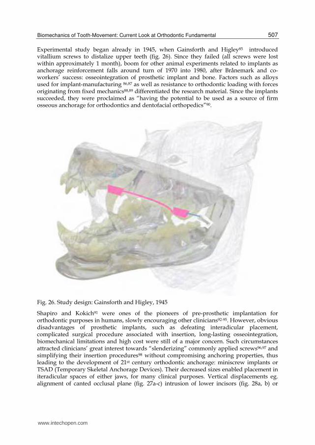
Experimental study began already in 1945, when Gainsforth and Higley85 introduced vitallium screws to distalize upper teeth (fig. 26). Since they failed (all screws were lost within approximately 1 month), boom for other animal experiments related to implants as anchorage reinforcement falls around turn of 1970 into 1980, after Brånemark and co-workers’ success: osseointegration of prosthetic implant and bone. Factors such as alloys used for implant-manufacturing 86,87 as well as resistance to orthodontic loading with forces originating from fixed mechanics88,89 differentiated the research material. Since the implants succeeded, they were proclaimed as “having the potential to be used as a source of firm osseous anchorage for orthodontics and dentofacial orthopedics”90.
Fig. 26. Study design: Gainsforth and Higley, 1945
Shapiro and Kokich91 were ones of the pioneers of pre-prosthetic implantation for orthodontic purposes in humans, slowly encouraging other clinicians92-95. However, obvious disadvantages of prosthetic implants, such as defeating interadicular placement, complicated surgical procedure associated with insertion, long-lasting osseointegration, biomechanical limitations and high cost were still of a major concern. Such circumstances attracted clinicians’ great interest towards “slenderizing” commonly applied screws96,97 and simplifying their insertion procedures98 without compromising anchoring properties, thus leading to the development of 21st century orthodontic anchorage: miniscrew implants or TSAD (Temporary Skeletal Anchorage Devices). Their decreased sizes enabled placement in iteradicular spaces of either jaws, for many clinical purposes. Vertical displacements eg. alignment of canted occlusal plane (fig. 27a-c) intrusion of lower incisors (fig. 28a, b) or
www.intechopen.com
Principles in Contemporary Orthodontics
508
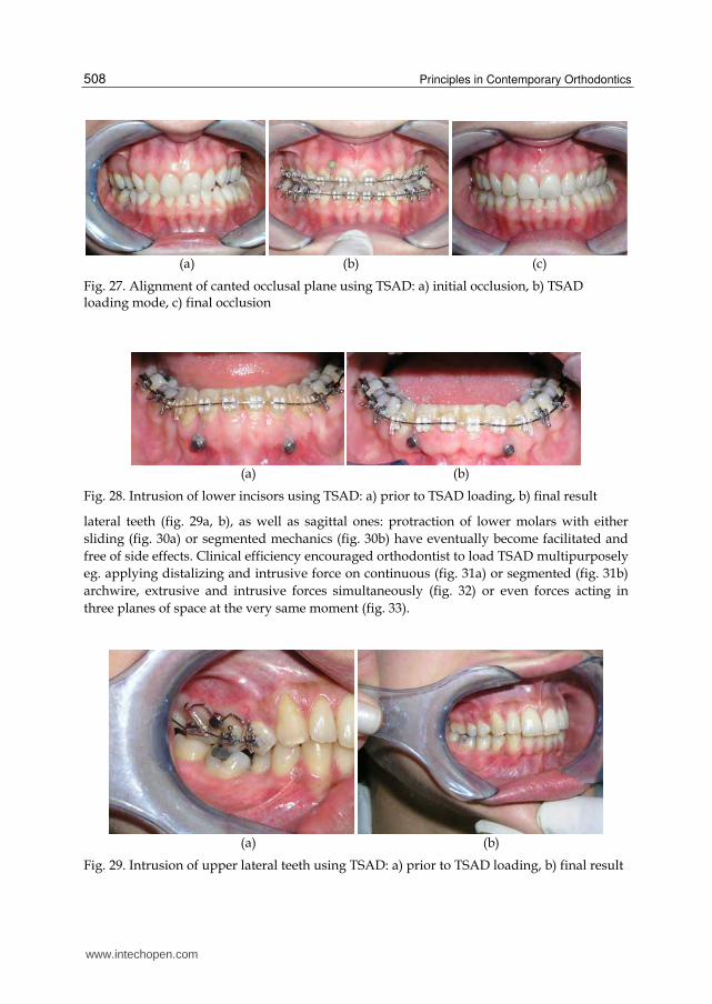
(a) (b) (c)
Fig. 27. Alignment of canted occlusal plane using TSAD: a) initial occlusion, b) TSAD loading mode, c) final occlusion
(a) (b)
Fig. 28. Intrusion of lower incisors using TSAD: a) prior to TSAD loading, b) final result
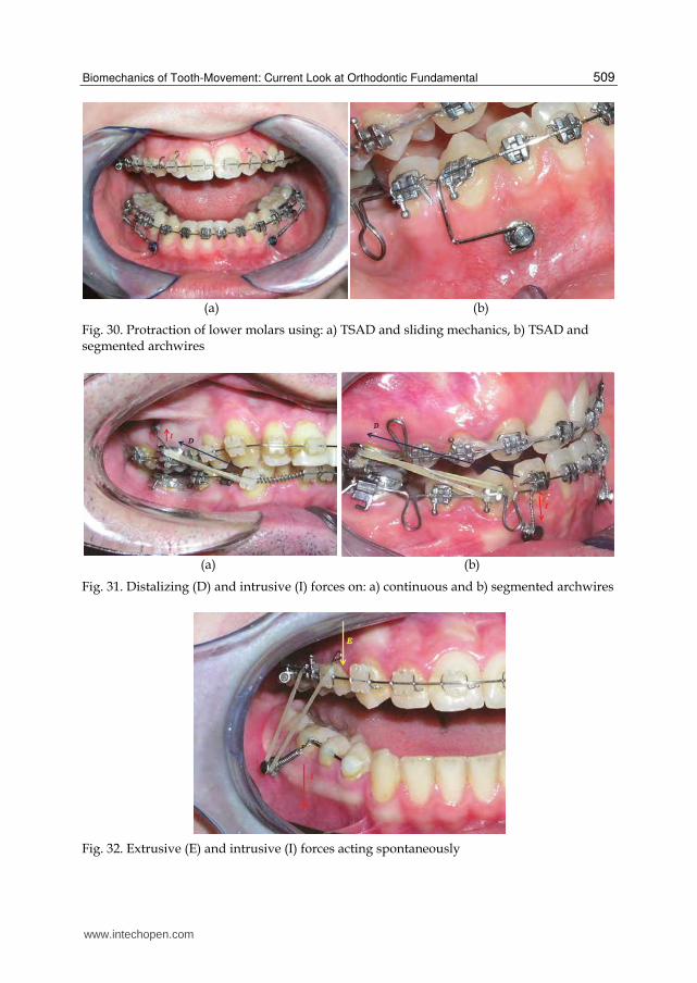
lateral teeth (fig. 29a, b), as well as sagittal ones: protraction of lower molars with either
sliding (fig. 30a) or segmented mechanics (fig. 30b) have eventually become facilitated and
free of side effects. Clinical efficiency encouraged orthodontist to load TSAD multipurposely
eg. applying distalizing and intrusive force on continuous (fig. 31a) or segmented (fig. 31b)
archwire, extrusive and intrusive forces simultaneously (fig. 32) or even forces acting in
three planes of space at the very same moment (fig. 33).
(a) (b)
Fig. 29. Intrusion of upper lateral teeth using TSAD: a) prior to TSAD loading, b) final result
www.intechopen.com
Biomechanics of Tooth-Movement: Current Look at Orthodontic Fundamental
509
(a) (b)
Fig. 30. Protraction of lower molars using: a) TSAD and sliding mechanics, b) TSAD and segmented archwires
(a) (b)
Fig. 31. Distalizing (D) and intrusive (I) forces on: a) continuous and b) segmented archwires
Fig. 32. Extrusive (E) and intrusive (I) forces acting spontaneously
www.intechopen.com
Principles in Contemporary Orthodontics
510
Fig. 33. Transversal, vertical and sagittal forces acting simultaneously
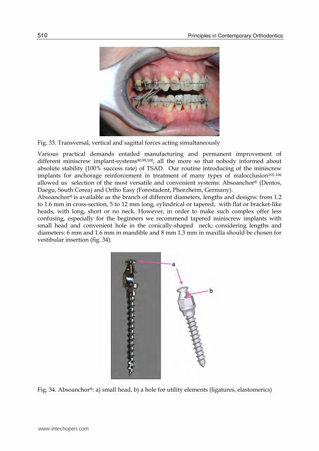
Various practical demands entailed manufacturing and permanent improvement of different miniscrew implant-systems90,99,100, all the more so that nobody informed about absolute stability (100% success rate) of TSAD. Our routine introducing of the miniscrew implants for anchorage reinforcement in treatment of many types of malocclusion101-106 allowed us selection of the most versatile and convenient systems: Absoanchor® (Dentos, Daegu, South Corea) and Ortho Easy (Forestadent, Phorzheim, Germany). Absoanchor® is available as the branch of different diameters, lengths and designs: from 1.2 to 1.6 mm in cross-section, 5 to 12 mm long, cylindrical or tapered, with flat or bracket-like heads, with long, short or no neck. However, in order to make such complex offer less confusing, especially for the beginners we recommend tapered miniscrew implants with small head and convenient hole in the conically-shaped neck; considering lengths and diameters: 6 mm and 1.6 mm in mandible and 8 mm 1.3 mm in maxilla should be chosen for vestibular insertion (fig. 34).
Fig. 34. Absoanchor®: a) small head, b) a hole for utility elements (ligatures, elastomerics)
www.intechopen.com
Biomechanics of Tooth-Movement: Current Look at Orthodontic Fundamental
511
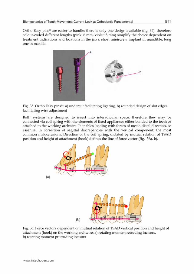
Ortho Easy pins® are easier to handle: there is only one design available (fig. 35), therefore colour-coded different lengths (pink: 6 mm, violet: 8 mm) simplify the choice dependent on treatment indications and locations in the jaws: short miniscrew implant in mandible, long one in maxilla.
Fig. 35. Ortho Easy pins® : a) undercut facilitating ligating, b) rounded design of slot edges facilitating wire adjustment
Both systems are designed to insert into interadicular space, therefore they may be connected via coil spring with the elements of fixed appliances either bonded to the teeth or attached to the working archwire. It enables loading with forces of mesio-distal direction, so essential in correction of sagittal discrepancies with the vertical component: the most common malocclusions. Direction of the coil spring, dictated by mutual relation of TSAD position and height of attachment (hook) defines the line of force vector (fig. 36a, b).
Fig. 36. Force vectors dependent on mutual relation of TSAD vertical position and height of attachment (hook) on the working archwire: a) rotating moment retruding incisors, b) rotating moment protruding incisors
(a)
(b)
www.intechopen.com
Principles in Contemporary Orthodontics
512
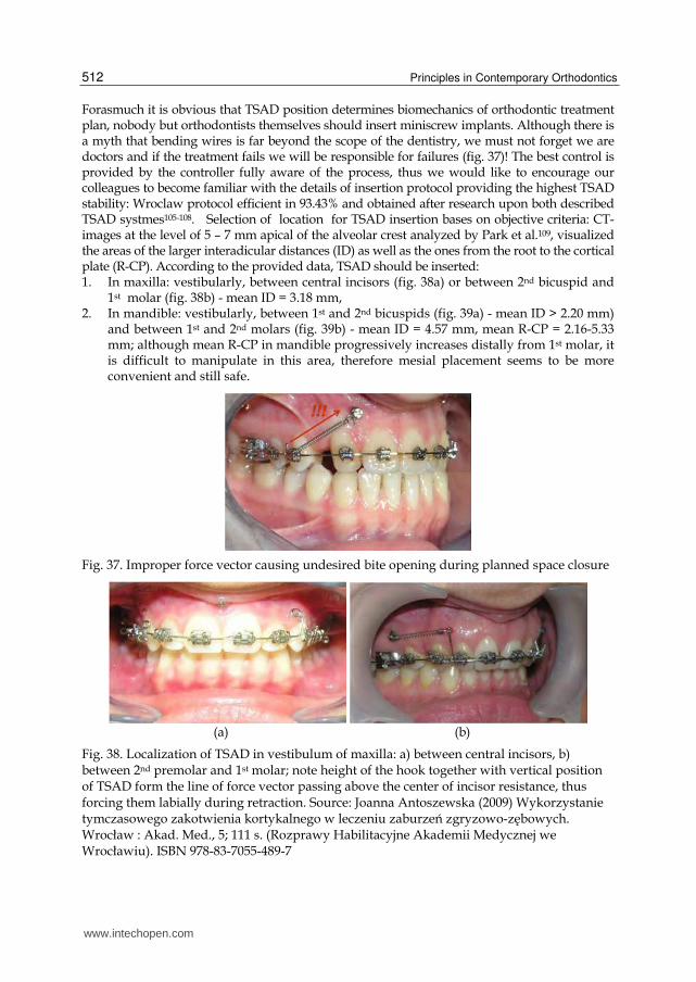
Forasmuch it is obvious that TSAD position determines biomechanics of orthodontic treatment plan, nobody but orthodontists themselves should insert miniscrew implants. Although there is a myth that bending wires is far beyond the scope of the dentistry, we must not forget we are doctors and if the treatment fails we will be responsible for failures (fig. 37)! The best control is provided by the controller fully aware of the process, thus we would like to encourage our colleagues to become familiar with the details of insertion protocol providing the highest TSAD stability: Wroclaw protocol efficient in 93.43% and obtained after research upon both described TSAD systmes105-108. Selection of location for TSAD insertion bases on objective criteria: CT-images at the level of 5 – 7 mm apical of the alveolar crest analyzed by Park et al.109, visualized the areas of the larger interadicular distances (ID) as well as the ones from the root to the cortical plate (R-CP). According to the provided data, TSAD should be inserted: 1. In maxilla: vestibularly, between central incisors (fig. 38a) or between 2nd bicuspid and
1st molar (fig. 38b) - mean ID = 3.18 mm, 2. In mandible: vestibularly, between 1st and 2nd bicuspids (fig. 39a) - mean ID > 2.20 mm)
and between 1st and 2nd molars (fig. 39b) - mean ID = 4.57 mm, mean R-CP = 2.16-5.33 mm; although mean R-CP in mandible progressively increases distally from 1st molar, it is difficult to manipulate in this area, therefore mesial placement seems to be more convenient and still safe.
Fig. 37. Improper force vector causing undesired bite opening during planned space closure
(a) (b)
Fig. 38. Localization of TSAD in vestibulum of maxilla: a) between central incisors, b) between 2nd premolar and 1st molar; note height of the hook together with vertical position of TSAD form the line of force vector passing above the center of incisor resistance, thus forcing them labially during retraction. Source: Joanna Antoszewska (2009) Wykorzystanie tymczasowego zakotwienia kortykalnego w leczeniu zaburzeń zgryzowo-zębowych. Wrocław : Akad. Med., 5; 111 s. (Rozprawy Habilitacyjne Akademii Medycznej we Wrocławiu). ISBN 978-83-7055-489-7
www.intechopen.com
Biomechanics of Tooth-Movement: Current Look at Orthodontic Fundamental
513
(a) (b)
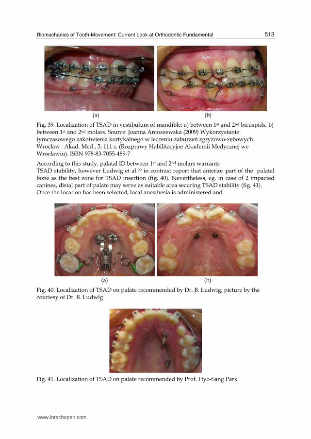
Fig. 39. Localization of TSAD in vestibulum of mandible: a) between 1st and 2nd bicuspids, b) between 1st and 2nd molars. Source: Joanna Antoszewska (2009) Wykorzystanie tymczasowego zakotwienia kortykalnego w leczeniu zaburzeń zgryzowo-zębowych. Wrocław : Akad. Med., 5; 111 s. (Rozprawy Habilitacyjne Akademii Medycznej we Wrocławiu). ISBN 978-83-7055-489-7
According to this study, palatal ID between 1st and 2nd molars warrants TSAD stability, however Ludwig et al.99 in contrast report that anterior part of the palatal bone as the best zone for TSAD insertion (fig. 40). Nevertheless, eg. in case of 2 impacted canines, distal part of palate may serve as suitable area securing TSAD stability (fig. 41). Once the location has been selected, local anesthesia is administered and
(a) (b)
Fig. 40. Localization of TSAD on palate recommended by Dr. B. Ludwig; picture by the courtesy of Dr. B. Ludwig
Fig. 41. Localization of TSAD on palate recommended by Prof. Hyo-Sang Park
www.intechopen.com
Principles in Contemporary Orthodontics
514
(a) (b)
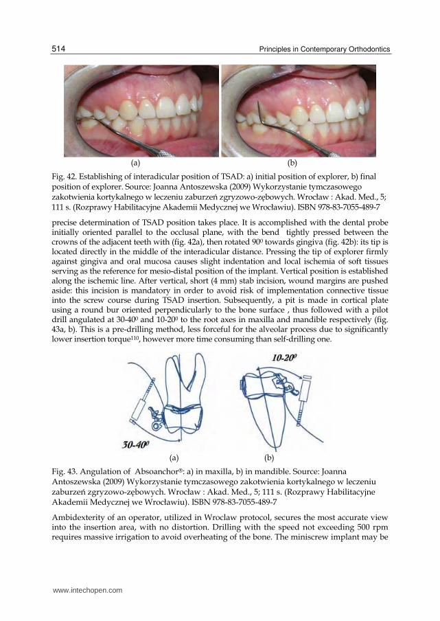
Fig. 42. Establishing of interadicular position of TSAD: a) initial position of explorer, b) final position of explorer. Source: Joanna Antoszewska (2009) Wykorzystanie tymczasowego zakotwienia kortykalnego w leczeniu zaburzeń zgryzowo-zębowych. Wrocław : Akad. Med., 5; 111 s. (Rozprawy Habilitacyjne Akademii Medycznej we Wrocławiu). ISBN 978-83-7055-489-7
precise determination of TSAD position takes place. It is accomplished with the dental probe initially oriented parallel to the occlusal plane, with the bend tightly pressed between the crowns of the adjacent teeth with (fig. 42a), then rotated 900 towards gingiva (fig. 42b): its tip is located directly in the middle of the interadicular distance. Pressing the tip of explorer firmly against gingiva and oral mucosa causes slight indentation and local ischemia of soft tissues serving as the reference for mesio-distal position of the implant. Vertical position is established along the ischemic line. After vertical, short (4 mm) stab incision, wound margins are pushed aside: this incision is mandatory in order to avoid risk of implementation connective tissue into the screw course during TSAD insertion. Subsequently, a pit is made in cortical plate using a round bur oriented perpendicularly to the bone surface , thus followed with a pilot drill angulated at 30-400 and 10-200 to the root axes in maxilla and mandible respectively (fig. 43a, b). This is a pre-drilling method, less forceful for the alveolar process due to significantly lower insertion torque110, however more time consuming than self-drilling one.
(a) (b)
Fig. 43. Angulation of Absoanchor®: a) in maxilla, b) in mandible. Source: Joanna Antoszewska (2009) Wykorzystanie tymczasowego zakotwienia kortykalnego w leczeniu zaburzeń zgryzowo-zębowych. Wrocław : Akad. Med., 5; 111 s. (Rozprawy Habilitacyjne Akademii Medycznej we Wrocławiu). ISBN 978-83-7055-489-7
Ambidexterity of an operator, utilized in Wroclaw protocol, secures the most accurate view into the insertion area, with no distortion. Drilling with the speed not exceeding 500 rpm requires massive irrigation to avoid overheating of the bone. The miniscrew implant may be
www.intechopen.com
Biomechanics of Tooth-Movement: Current Look at Orthodontic Fundamental
515
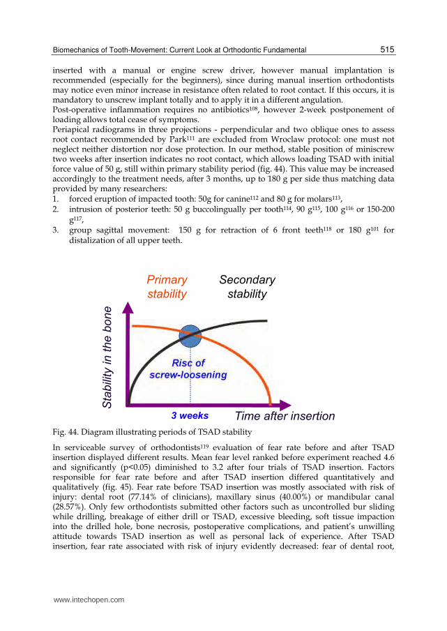
inserted with a manual or engine screw driver, however manual implantation is recommended (especially for the beginners), since during manual insertion orthodontists may notice even minor increase in resistance often related to root contact. If this occurs, it is mandatory to unscrew implant totally and to apply it in a different angulation. Post-operative inflammation requires no antibiotics108, however 2-week postponement of loading allows total cease of symptoms. Periapical radiograms in three projections - perpendicular and two oblique ones to assess root contact recommended by Park111 are excluded from Wroclaw protocol: one must not neglect neither distortion nor dose protection. In our method, stable position of miniscrew two weeks after insertion indicates no root contact, which allows loading TSAD with initial force value of 50 g, still within primary stability period (fig. 44). This value may be increased accordingly to the treatment needs, after 3 months, up to 180 g per side thus matching data provided by many researchers: 1. forced eruption of impacted tooth: 50g for canine112 and 80 g for molars113, 2. intrusion of posterior teeth: 50 g buccolingually per tooth114, 90 g115, 100 g116 or 150-200
g117, 3. group sagittal movement: 150 g for retraction of 6 front teeth118 or 180 g101 for
distalization of all upper teeth.
Fig. 44. Diagram illustrating periods of TSAD stability
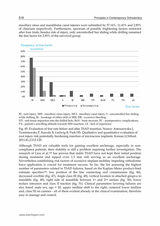
In serviceable survey of orthodontists119 evaluation of fear rate before and after TSAD insertion displayed different results. Mean fear level ranked before experiment reached 4.6 and significantly (p<0.05) diminished to 3.2 after four trials of TSAD insertion. Factors responsible for fear rate before and after TSAD insertion differed quantitatively and qualitatively (fig. 45). Fear rate before TSAD insertion was mostly associated with risk of injury: dental root (77.14% of clinicians), maxillary sinus (40.00%) or mandibular canal (28.57%). Only few orthodontists submitted other factors such as uncontrolled bur sliding while drilling, breakage of either drill or TSAD, excessive bleeding, soft tissue impaction into the drilled hole, bone necrosis, postoperative complications, and patient’s unwilling attitude towards TSAD insertion as well as personal lack of experience. After TSAD insertion, fear rate associated with risk of injury evidently decreased: fear of dental root,
www.intechopen.com
Principles in Contemporary Orthodontics
516
maxillary sinus and mandibular canal injuries were submitted by 57.14%, 11.43% and 2.85% of clinicians respectively. Furthermore, spectrum of possibly frightening factors restricted after four trials; besides risk of injury, only uncontrolled bur sliding while drilling remained the fear factor for 2.85% of the surveyed group.
RI - root injury, MSI - maxillary sinus injury, MCI - maxillary canal injury, S - uncontrolled bur sliding while drilling, Br - breakage of either drill or MSI, EBl - excessive bleeding, STI - soft tissue impaction into the drilled hole, BoN - bone necrosis, PC - postoperative complications, PA - patient’s unwilling attitude towards MSI insertion, LE - lack of experience
Fig. 45. Evaluation of fear rate before and after TSAD insertion. Source: Antoszewska J, Trześniewska P, Kawala B, Ludwig B, Park HS. Qualitative and quantitative evaluation of root injury risk potentially burdening insertion of microscrew implants. Korean J.Orthod. 2011;41,2:112-120
Although TSAD are valuable tools for gaining excellent anchorage, especially in non-
compliance patients, their stability is still a problem requiring further investigation. The
research of Liou et al.120 has proven that stable TSAD have not kept their initial position
during treatment and tipped even 1.5 mm still serving as an excellent anchorage.
Nevertheless establishing risk factors of excessive implant mobility impeding orthodontic
force application is crucial for treatment success. So far, the list assessing the highest
number of parameters related to TSAD failures, based on the Kaplan–Meier product-limit
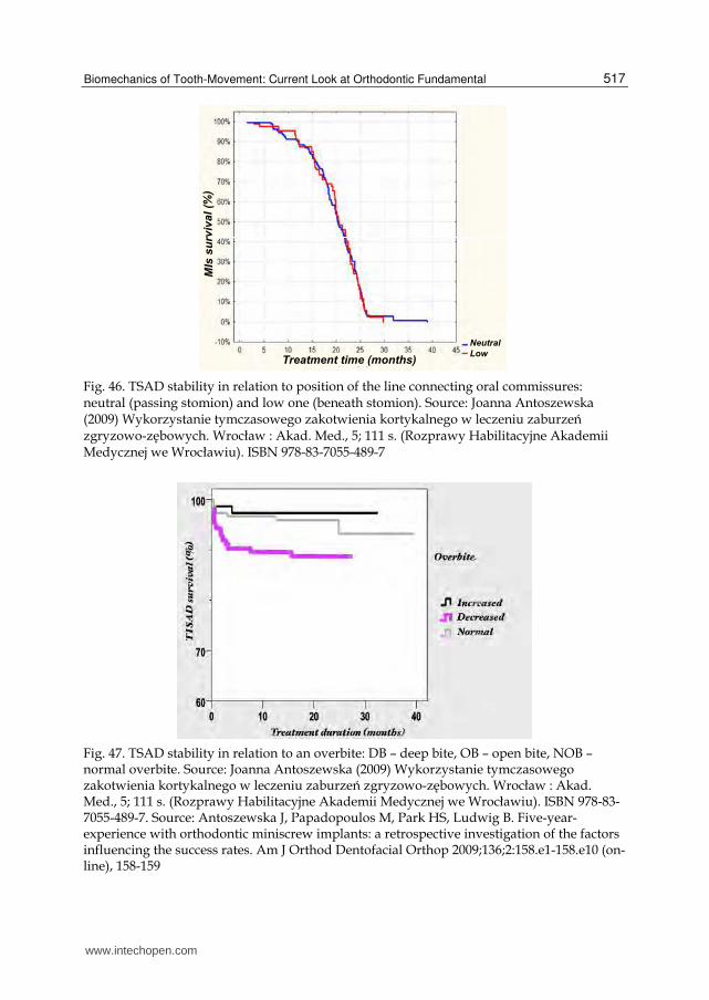
estimate specifies105: low position of the line connecting oral commissures (fig. 46),
decreased overbite (fig. 47), Angle class III (fig. 48), vertical location in attached gingiva in
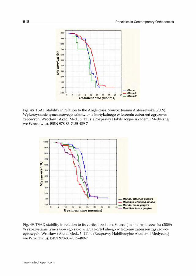
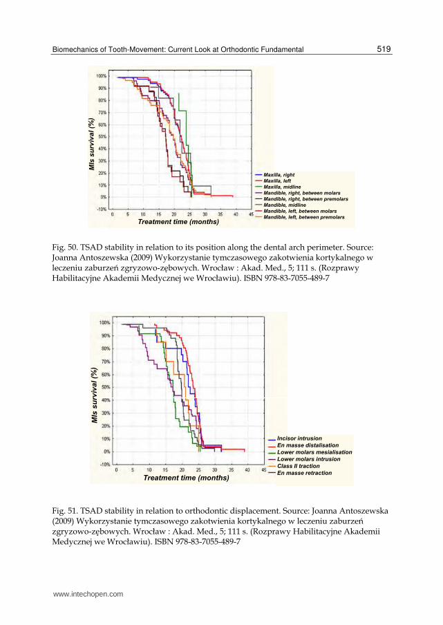
mandible (fig. 49), right side of mandible between 1st and 2nd molars (fig. 50), lower
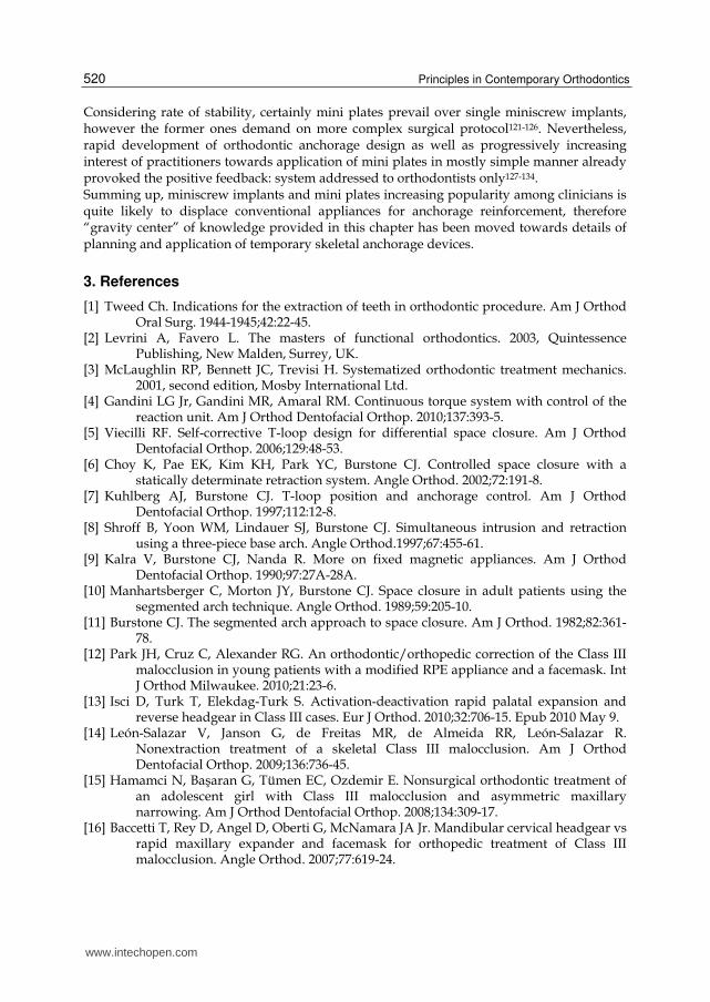
molars intrusion and class II traction (fig. 51). Clinical parameters favoring failures are
also listed: male sex, age < 20, upper midline shift to the right, centered lower midline
and, class III on canines - all of them evident already at the clinical examination, therefore
easy to manage and control.
Frequency of fear factor occurence
Fear factor
www.intechopen.com
Biomechanics of Tooth-Movement: Current Look at Orthodontic Fundamental
517
Fig. 46. TSAD stability in relation to position of the line connecting oral commissures: neutral (passing stomion) and low one (beneath stomion). Source: Joanna Antoszewska (2009) Wykorzystanie tymczasowego zakotwienia kortykalnego w leczeniu zaburzeń zgryzowo-zębowych. Wrocław : Akad. Med., 5; 111 s. (Rozprawy Habilitacyjne Akademii Medycznej we Wrocławiu). ISBN 978-83-7055-489-7
Fig. 47. TSAD stability in relation to an overbite: DB – deep bite, OB – open bite, NOB – normal overbite. Source: Joanna Antoszewska (2009) Wykorzystanie tymczasowego zakotwienia kortykalnego w leczeniu zaburzeń zgryzowo-zębowych. Wrocław : Akad. Med., 5; 111 s. (Rozprawy Habilitacyjne Akademii Medycznej we Wrocławiu). ISBN 978-83-7055-489-7. Source: Antoszewska J, Papadopoulos M, Park HS, Ludwig B. Five-year-experience with orthodontic miniscrew implants: a retrospective investigation of the factors influencing the success rates. Am J Orthod Dentofacial Orthop 2009;136;2:158.e1-158.e10 (on- line), 158-159
www.intechopen.com
Principles in Contemporary Orthodontics
518
Fig. 48. TSAD stability in relation to the Angle class. Source: Joanna Antoszewska (2009) Wykorzystanie tymczasowego zakotwienia kortykalnego w leczeniu zaburzeń zgryzowo-zębowych. Wrocław : Akad. Med., 5; 111 s. (Rozprawy Habilitacyjne Akademii Medycznej we Wrocławiu). ISBN 978-83-7055-489-7
Fig. 49. TSAD stability in relation to its vertical position. Source: Joanna Antoszewska (2009) Wykorzystanie tymczasowego zakotwienia kortykalnego w leczeniu zaburzeń zgryzowo-zębowych. Wrocław : Akad. Med., 5; 111 s. (Rozprawy Habilitacyjne Akademii Medycznej we Wrocławiu). ISBN 978-83-7055-489-7
www.intechopen.com
Biomechanics of Tooth-Movement: Current Look at Orthodontic Fundamental
519
Fig. 50. TSAD stability in relation to its position along the dental arch perimeter. Source: Joanna Antoszewska (2009) Wykorzystanie tymczasowego zakotwienia kortykalnego w leczeniu zaburzeń zgryzowo-zębowych. Wrocław : Akad. Med., 5; 111 s. (Rozprawy Habilitacyjne Akademii Medycznej we Wrocławiu). ISBN 978-83-7055-489-7
Fig. 51. TSAD stability in relation to orthodontic displacement. Source: Joanna Antoszewska (2009) Wykorzystanie tymczasowego zakotwienia kortykalnego w leczeniu zaburzeń zgryzowo-zębowych. Wrocław : Akad. Med., 5; 111 s. (Rozprawy Habilitacyjne Akademii Medycznej we Wrocławiu). ISBN 978-83-7055-489-7
www.intechopen.com
Principles in Contemporary Orthodontics
520
Considering rate of stability, certainly mini plates prevail over single miniscrew implants, however the former ones demand on more complex surgical protocol121-126. Nevertheless, rapid development of orthodontic anchorage design as well as progressively increasing interest of practitioners towards application of mini plates in mostly simple manner already provoked the positive feedback: system addressed to orthodontists only127-134. Summing up, miniscrew implants and mini plates increasing popularity among clinicians is quite likely to displace conventional appliances for anchorage reinforcement, therefore “gravity center” of knowledge provided in this chapter has been moved towards details of planning and application of temporary skeletal anchorage devices.
3. References
[1] Tweed Ch. Indications for the extraction of teeth in orthodontic procedure. Am J Orthod Oral Surg. 1944-1945;42:22-45.
[2] Levrini A, Favero L. The masters of functional orthodontics. 2003, Quintessence Publishing, New Malden, Surrey, UK.
[3] McLaughlin RP, Bennett JC, Trevisi H. Systematized orthodontic treatment mechanics. 2001, second edition, Mosby International Ltd.
[4] Gandini LG Jr, Gandini MR, Amaral RM. Continuous torque system with control of the reaction unit. Am J Orthod Dentofacial Orthop. 2010;137:393-5.
[5] Viecilli RF. Self-corrective T-loop design for differential space closure. Am J Orthod Dentofacial Orthop. 2006;129:48-53.
[6] Choy K, Pae EK, Kim KH, Park YC, Burstone CJ. Controlled space closure with a statically determinate retraction system. Angle Orthod. 2002;72:191-8.
[7] Kuhlberg AJ, Burstone CJ. T-loop position and anchorage control. Am J Orthod Dentofacial Orthop. 1997;112:12-8.
[8] Shroff B, Yoon WM, Lindauer SJ, Burstone CJ. Simultaneous intrusion and retraction using a three-piece base arch. Angle Orthod.1997;67:455-61.
[9] Kalra V, Burstone CJ, Nanda R. More on fixed magnetic appliances. Am J Orthod Dentofacial Orthop. 1990;97:27A-28A.
[10] Manhartsberger C, Morton JY, Burstone CJ. Space closure in adult patients using the segmented arch technique. Angle Orthod. 1989;59:205-10.
[11] Burstone CJ. The segmented arch approach to space closure. Am J Orthod. 1982;82:361-78.
[12] Park JH, Cruz C, Alexander RG. An orthodontic/orthopedic correction of the Class III malocclusion in young patients with a modified RPE appliance and a facemask. Int J Orthod Milwaukee. 2010;21:23-6.
[13] Isci D, Turk T, Elekdag-Turk S. Activation-deactivation rapid palatal expansion and reverse headgear in Class III cases. Eur J Orthod. 2010;32:706-15. Epub 2010 May 9.
[14] León-Salazar V, Janson G, de Freitas MR, de Almeida RR, León-Salazar R. Nonextraction treatment of a skeletal Class III malocclusion. Am J Orthod Dentofacial Orthop. 2009;136:736-45.
[15] Hamamci N, Başaran G, Tümen EC, Ozdemir E. Nonsurgical orthodontic treatment of an adolescent girl with Class III malocclusion and asymmetric maxillary narrowing. Am J Orthod Dentofacial Orthop. 2008;134:309-17.
[16] Baccetti T, Rey D, Angel D, Oberti G, McNamara JA Jr. Mandibular cervical headgear vs rapid maxillary expander and facemask for orthopedic treatment of Class III malocclusion. Angle Orthod. 2007;77:619-24.
www.intechopen.com
Biomechanics of Tooth-Movement: Current Look at Orthodontic Fundamental
521
[17] Pangrazio-Kulbersh V, Berger JL, Janisse FN, Bayirli B. Long-term stability of Class III treatment: rapid palatal expansion and protraction facemask vs LeFort I maxillary advancement osteotomy. Am J Orthod Dentofacial Orthop. 2007;131:7.e9-19.
[18] Kama JD, Ozer T, Baran S. Orthodontic and orthopaedic changes associated with treatment in subjects with Class III malocclusions. Eur J Orthod. 2006;28:496-502. Epub 2006 Jun 13.
[19] Arman A, Ufuk Toygar T, Abuhijleh E. Evaluation of maxillary protraction and fixed appliance therapy in Class III patients. Eur J Orthod. 2006;28:383-92. Epub 2006 May 26.
[20] Liou EJ. Effective maxillary orthopedic protraction for growing Class III patients: a clinical application simulates distraction osteogenesis. Prog Orthod. 2005;6:154-71.
[21] Arslan SG, Kama JD, Baran S. Correction of a severe Class III malocclusion. Am J Orthod Dentofacial Orthop. 2004;126:237-44.
[22] Westwood PV, McNamara JA Jr, Baccetti T, Franchi L, Sarver DM. Long-term effects of Class III treatment with rapid maxillary expansion and facemask therapy followed by fixed appliances. Am J Orthod Dentofacial Orthop. 2003;123:306-20.
[23] Cha KS. Skeletal changes of maxillary protraction in patients exhibiting skeletal class III malocclusion: a comparison of three skeletal maturation groups. Angle Orthod. 2003;73:26-35.
[24] Keles A, Tokmak EC, Erverdi N, Nanda R. Effect of varying the force direction on maxillary orthopedic protraction. Angle Orthod. 2002;72:387-96.
[25] Baccetti T, Franchi L, McNamara JA Jr. Treatment and posttreatment craniofacial changes after rapid maxillary expansion and facemask therapy. Am J Orthod Dentofacial Orthop. 2000;118:404-13.
[26] Lima Filho RM, de Oliveira Ruellas AC. Long-term maxillary changes in patients with skeletal Class II malocclusion treated with slow and rapid palatal expansion. Am J Orthod Dentofacial Orthop. 2008;134:383-8.
[27] Lima Filho RM, Ruellas AC. Long-term anteroposterior and vertical maxillary changes in skeletal class II patients treated with slow and rapid maxillary expansion. Angle Orthod. 2007;77:870-4.
[28] Lima Filho RM, de Oliveira Ruellas AC. Mandibular behavior with slow and rapid maxillary expansion in skeletal Class II patients: a long-term study. Angle Orthod. 2007;77:625-31.
[29] Frye L, Diedrich PR, Kinzinger GS. Class II treatment with fixed functional orthodontic appliances before and after the pubertal growth peak – a cephalometric study to evaluate differential therapeutic effects. J Orofac Orthop. 2009;70:511-27.
[30] Siara-Olds NJ, Pangrazio-Kulbersh V, Berger J, Bayirli B. Long-term dentoskeletal changes with the Bionator, Herbst, Twin Block, and MARA functional appliances. Angle Orthod. 2010;80:18-29.
[31] Chaiyongsirisern A, Rabie AB, Wong RW. Stepwise advancement Herbst appliance versus mandibular sagittal split osteotomy. Treatment effects and long-term stability of adult Class II patients. Angle Orthod. 2009;79:1084-94.
[32] Panigrahi P, Vineeth V. Biomechanical effects of fixed functional appliance on craniofacial structures. Angle Orthod. 2009;79:668-75.
[33] Kinzinger G, Frye L, Diedrich P. Class II treatment in adults: comparing camouflage orthodontics, dentofacial orthopedics and orthognathic surgery – a cephalometric study to evaluate various therapeutic effects. J Orofac Orthop. 2009;70:63-91. Epub 2009 Feb 5.
www.intechopen.com
Principles in Contemporary Orthodontics
522
[34] Sloss EA, Southard KA, Qian F, Stock SE, Mann KR, Meyer DL, Southard TE. Comparison of soft-tissue profiles after treatment with headgear or Herbst appliance. Am J Orthod Dentofacial Orthop. 2008;133:509-14.
[35] Giannasi LC, Magini M, de Oliveira CS, de Oliveira LV. Treatment of obstructive sleep apnea using an adjustable mandibular repositioning appliance fitted to a total prosthesis in a maxillary edentulous patient. Sleep Breath. 2008;12:91-5.
[36] Naini FB, Gill DS, Payne E, Keel B. Medium Opening Activator: design, applications for the management of class II deep overbite malocclusion. World J Orthod. 2007;8:e1-9.
[37] VanLaecken R, Martin CA, Dischinger T, Razmus T, Ngan P. Treatment effects of the edgewise Herbst appliance: a cephalometric and tomographic investigation. Am J Orthod Dentofacial Orthop. 2006;130:582-93.
[38] Kinzinger G, Gülden N, Roth A, Diedrich P. Disc-condyle relationships during class II Treatment with the functional mandibular advancer (FMA). J Orofac Orthop. 2006;67:356-75.
[39] Bass NM. The Dynamax system: a new orthopaedic appliance and case report. J Orthod. 2006;33:78-89.
[40] Shen G, Hägg U, Darendeliler M. Skeletal effects of bite jumping therapy on the mandible - removable vs. fixed functional appliances. Orthod Craniofac Res.2005;8:2-10.
[41] Voudouris JC, Woodside DG, Altuna G, Angelopoulos G, Bourque PJ, Lacouture CY, Kuftinec MM. Condyle-fossa modifications and muscle interactions during Herbst treatment, Part 2. Results and conclusions. Am J Orthod Dentofacial Orthop. 2003;124:13-29.
[42] Voudouris JC, Woodside DG, Altuna G, Kuftinec MM, Angelopoulos G, Bourque PJ. Condyle-fossa modifications and muscle interactions during herbst treatment, part 1: new technological methods. Am J Orthod Dentofacial Orthop. 2003;123:604-13.
[43] Kinzinger G, Ostheimer J, Förster F, Kwandt PB, Reul H, Diedrich P. Development of a new fixed functional appliance for treatment of skeletal class II malocclusion first report. J Orofac Orthop. 2002;63:384-99.
[44] Dolce C, Van Sickels JE, Bays RA, Rugh JD. Skeletal stability after mandibular advancement with rigid versus wire fixation. J Oral Maxillofac Surg. 2000;58:1219-27.
[45] Blomqvist JE, Isaksson S. Skeletal stability after mandibular advancement: a comparison of two rigid internal fixation techniques. J Oral Maxillofac Surg. 1994;52:1133-7.
[46] Sadowsky C, Schneider BJ, BeGole EA, Tahir E. Long-term stability after orthodontic treatment: nonextraction with prolonged retention. Am J Orthod Dentofacial Orthop. 1994;106:243-9.
[47] Newton I. Philosophiae Naturalis Principia Mathematica, 1687, S. Pepys, Reg. Sor. Praeses, London.
[48] Melsen B, Fotis V, Burstone CJ. Vertical force considerations in differential space closure. J Clin Orthod. 1990;24:678-83.
[49] Sifakakis I, Pandis N, Makou M, Eliades T, Bourauel C. Forces and moments on posterior teeth generated by incisor intrusion biomechanics. Orthod Craniofac Res. 2009;12:305-11.
[50] Badawi HM, Toogood RW, Carey JP, Heo G, Major PW. Three-dimensional orthodontic force measurements. Am J Orthod Dentofacial Orthop. 2009;136:518-28.
[51] Cattaneo PM, Dalstra M, Melsen B. Moment-to-force ratio, center of rotation, and force level: a finite element study predicting their interdependency for simulated orthodontic loading regimens. Am J Orthod Dentofacial Orthop. 2008;133:681-9.
www.intechopen.com
Biomechanics of Tooth-Movement: Current Look at Orthodontic Fundamental
523
[52] Proffit WR, Fields HW Jr., Sarver DM. Contemporary Orthodontics. 2006, Elsevier Health Sciences, Edition 4.
[53] Teuscher UM. An appraisal of growth and reaction to extraoral anchorage. Am J Orthod 1986;89:113-21.
[54] Schmuth GPF, Holtgrave EA, Drescher DISBN: 83-87601-20-9, Czelej, Wydanie 1, [55] Braun S. Extraoral appliances: a twenty-first century update. Am J Orthod Dentofacial
Orthop 2004;125:624-9. [56] Melsen B, Bosch C. Different approaches to anchorage: a survey and evaluation. Angle
Orthod 1997;67;1:23-30. [57] Steger ES, Blechman AM. Case reports: molar distalization with static repelling
magnets. Part II. Am J Orthod Dentofacial Orthop 1995;108:547-55. [58] Bondemark L. A comparative analysis of distal maxillary molar movement produced by
a new lingual intra-arch coil appliance and magnetic appliance. Eur J Orthod 2000;22:683-95.
[59] Dunin-Wilczyńska I. Jednostronna dystalizacja pierwszego trzonowca górnego sprężyną ściśniętą. Ortod. Współcz. 2001;3;2:37-9.
[60] Gulati S, Kharbanda OP, Parkash H. Dental and skeletal changes after intra-oral molar distalization with sectional jig assembly. Am J Orthod Dentofacial Orthop 1998;114:319-27.
[61] Bolla E, Muratore F, Carano A, Bowman SJ. Evaluation of Maxillary Molar Distalization With the Distal Jet: A Comparison With Other Contemporary Methods. The Angle Orthodontist: October 2002, Vol. 72, No. 5, pp. 481-94.
[62] Paul LD, O’Brien KD, Mandall NA. Upper removable appliance or jones jig for distalizing first molars? A randomized clinical trial. Orthod Craniofacial Res 2002;5:238-42.
[63] Hilgers JJ. The pendulum appliance for class II non-compliance therapy. J Clin Orthod 1992;67:249-71.
[64] Keles A. Maxillary unilateral distalization with sliding mechanics. Eur J Orthod 2001;23:507-15.
[65] Roberts-Harry D, Sandy J. Orthodontics. Part 9: anchorage control and distal movement. British Dent J 2004;196;5:255-63.
[66] Pancherz H, Anehus-Pancherz M. The head-gear effect of the Herbst appliance. A cephalometric long-term study. Am J Orthod Dentofacial Orthop 1993;103:510-20.
[67] Carrière L. A new Class II distalizer. J Clin Orthod 2004;38:224-31. [68] Küçükkeleş N, Ilhan I, Orgun IA. Treatment efficiency in skeletal Class II patients
treated with the jasper jumper. Angle Orthod 2007;77:449-56. [69] Mulligan TF. Common sense mechanics in everyday orthodontics. 2009, CSM
Publishing, Phoenix, Arizona, USA. [70] Lloyd TG, Stephens CD. Spontaneous changes in molar occlusion after extraction of all
first premolars: a study of class II/1 cases treated with removable appliances. Br J Orth 1979;6:91-4.
[71] Stephens CD, Lloyd TG. Changes in molar occlusion after extraction of all first premolars: a follow up study of class II/1 cases treated with removable appliances. Br J Orth 1980;7:139-44.
[72] Taner TU, Yukay F., Pehlivanoglu M, Çakirer B. A comparative analysis of maxillary tooth movement produced by cervical headgear and pend-x appliance. Angle Orthod 2003;73:686-91.
www.intechopen.com
Principles in Contemporary Orthodontics
524
[73] Rudge SJ. A simplified method of applying extra-oral anchorage. Br Dent J 1981;152:205-6.
[74] Ghosh J, Nanda RS. Evaluation of intramolar distalization technique. Am J Orthod Dentofacial Orthop 1996;110:639-46.
[75] Byloff FK, Darandeliler MA. Distal molar movement using the pendulum appliance. Angle Orthod 1997;67:249-60.
[76] Bondemark L, Kurol J. Class II correction with magnets and super-elastic coils followed by straight-wire mechanotherapy. J Orofacial Orthop 1998;59:127-38.
[77] Alwali S, Marklund M, Persson M. Apical root resorption of upper first molars as related to anchorage system. Swed Dent J 2000;24:145-53.
[78] Bolla E, Muratore F, Carano A, Bowman J. Evaluation of maxillary molar distalization with the distal jet: a comparison with other temporary methods. Angle Orthod 2002;72:481-94.
[79] Brickman CD, Siha PK, Nanda RS. Evaluation of the jones jig appliance for distal molar movement. Am J Orthod Dentofacial Orthop 2000;118:526-34.
[80] Chiu PP. A comparison of two intraoral molar distalization appliances: distal jet versus pendulum appliance [unpublished master’s thesis]. Ann Arbor, Mich: Department of Orthodontics, University of Michigan, 2001.
[81] Langlade M. Clinical distalization with the distalix. World J Orthod 2003;4:215-28. [82] Paul LD, O’Brien KD, Mandall NA. Upper removable appliance or jones jig for
distalizing first molars? A randomized clinical trial. Orthod Craniofacial Res 2002;5:238-42.
[83] Firouz M, Zernik J, Nanda R.: Dental and orthopedic effects of high-pull headgear in treatment of class II division 1 malocclusion. Am J Orthod Dentofacial Orthop 1992;102:197-205.
[84] Ng J, Major P, Flores-Mir C. True molar intrusion attained during orthodontic treatment. Am J Orthod Dentofacial Orthop 2006;130:709-14.
[85] Gainsforth BL, Higley LB. A study of orthodontic anchorage possibilities in basal bone. Am J Orthod Oral Surg 1945;31:406-17.
[86] Sherman AJ. Bone reaction to orthodontic forces or vitreous carbon dental implants. Am J Orthod 1978;74:79-87.
[87] Smith JR. Bone dynamics associated with the controlled loading of bioglass-coated aluminum endosteal implants. Am J Orthod 1979;76:618-36.
[88] Majzoub Z, Finotti M, Miotti F, Giardino R, Cordioli G. Bone response to orthodontic loading of endosseous implants in the rabbit calvaria. Early continuous distalizing forces. Eur J Orthod 1999;21:223-30
[89] Roberts WE, Smith RK, Zilberman Y, Mozsary PG, Smith RS. Osseous adaptation to continuous loading of rigid endosseous implants. Am J Orthod 1984;86:95-111.
[90] Sung J.H., Kyung H.M., Bae S.M., Park H.S., Kwon O.W., McNamara J.A.: Microimplants in orthodontics. Daegu: Dentos 2006.
[91] Shapiro PA, Kokich VG. Use of implants in orthodontics. Dent Clin North Am 1988;32:539-50.
[92] Roberts WE, Nelson CL, Goodacre CJ. Rigid implant anchorage to close a mandibular first molar extraction site. J Clin Orthod 1994;28:693-704.
[93] Block MS, Hoffman DR. A new device of absolute anchorage for orthodontics. Am J Orthod Dentofacial Orthop 1995;107:251-8.
[94] Hong H, Ngan P, Li HG, Qi LG, Wei SHY. Use of onplants as stable anchorage for facemask treatment: a case report. Angle Orthod2005;75:453-60.
www.intechopen.com
Biomechanics of Tooth-Movement: Current Look at Orthodontic Fundamental
525
[95] Janssesns F, Swennen G, Dujardin T, Glineur R, Malevez C. Use of onplants as orthodontic anchorage. Am J Orthod Dentofacial Orthop 2002;122:566-70.
[96] Creekmore TD, Eklund MK. The possibility of skeletal anchorage. J Clin Orthod 1983;17:266-9.
[97] Kanomi R. Mini-implant for orthodontic anchorage. Int J Clin Orthod 1997;31:763-7. [98] Costa A, Raffini M, Melsen B. Microscrew as orthodontic anchorage. Int J Adult Orthod
Orthognath Surg 1998;13:201-9. [99] Ludwig B., Baumgaertel S., Bowman S.J.: Mini-implants in orthodontics. Berlin:
Quintesence 2008. [100] Cheol-Ho Paik CH, Park IK, Woo Y, Kim TW. Orthodontic miniscrew implants, clinical
applications. 2008 Mosby. [101] Antoszewska J. Class II division 2 treatment supported by absolute anchorage - case
report. Dent. Med. Probl. 2007;44;2:275-80. [102] Antoszewska J. Mikroimplanty systemu Absoanchor w leczeniu zgryzu otwartego -
opis przypadku. Ortod. Pol. 2007;1;1:23-8. [103] Antoszewska J, Minch L. Literature-based clinical application of microimplants in
treatment of different malocclusions. Dent. Med. Probl. 2006 43;1:11-4. [104] Antoszewska J, Sarul M, Kawala B. Asymetryczna dystalizacja zębów szczęki w
oparciu o mikroimplanty Absoanchor. Opis przypadku. Implantoprotetyka 2008;9;4:25-8.
[105] Antoszewska J. Wykorzystanie tymczasowego zakotwienia kortykalnego w leczeniu zaburzeń zgryzowo-zębowych. 2009, Wroclaw Medical University, habilitation thesis ISBN 978-83-7055-489-7.
[106] Antoszewska J, Papadopoulos M, Park HS, Ludwig B. Five-year-experience with orthodontic miniscrew implants: a retrospective investigation of the factors influencing the success rates. Am J Orthod Dentofacial Orthop 2009;136;2:158.e1-158.e10 (on- line), 158-159.
[107] Antoszewska J, Kawala B, Sarul M. Factors affecting stability of orthodontic implants. A Wroclaw method Forum Ortodont. 2010;6,1:5-14.
[108] Antoszewska J, Szeląg J. Pharmacotherapy in orthodontic treatment supported by micro-implants. Pharmacol Rep 2007;59;1:254-6.
[109] Park HS. An anatomical study using CT images for the implantation of micro-implants. Korea J Ortho 2002;32:435-41.
[110] Florvaag B, Kneuertz P, Lazar F, Koebke J, Zöller JE, Braumann B, Mischkowski RA.J Orofac Orthop. Biomechanical properties of orthodontic miniscrews. An in-vitro study. J Orofac Orthop. 2010;71:53-67. Epub 2010 Feb 5.
[111] Park HS. The skeletal cortical anchorage using titanium microscrew implants. Korea J. Orthod. 1999, 29:699-706.
[112] Park HS, Oh YH. Forced eruption of a labially impacted canine using joined micro-implants. J Clin Orthod. 2010;44:108-13; quiz 106.
[113] Janssens F, Swennen G, Dujardin T, Glineur R, Malevez C. Use of an onplant as orthodontic anchorage. Am J Orthod Dentofacial Orthop 2002;122:566-70.
[114] Melsen B, Fiorelli G. Upper molar intrusion. J Clin Orthod 1996;30:91-6. [115] Kalra V, Burstone CJ, Nanda R. Effects of a fixed magnetic appliance on the dentofacial
complex. Am J Orthod Dentofacial Orthop 1989;95:467-78. [116] Moon CH, Wee JU, Lee HS. Intrusion of overerupted molars by corticotomy and
orthodontic skeletal anchorage. Angle Orthod. 2007;77:1119-25.
www.intechopen.com
Principles in Contemporary Orthodontics
526
[117] Park YC, Lee SY, Kim DH, Jee SH. Intrusion of posterior teeth using mini-screw implants. Am J Orthod Dentofacial Orthop 2003;123:690-4.
[118] Park HS, Kwon TG. Sliding mechanics with microscrew implant anchorage. Angle Orthod. 2004;74:703-10.
[119] Antoszewska J, Trześniewska P, Kawala B, Park HS. Qualitative and quantitative evaluation of root injury risk potentially burdening insertion of microscrew implants. Korean J.Orthod. 2011;41,2:112-120.
[120] Liou EJ, Pai BC, Lin JC. Do miniscrews remain stationary under orthodontic forces? Am J Orthod Dentofacial Orthop 2004;126:42-7.
[121] Choi BH, Zhu SJ, Kim YH. A clinical evaluation of titanium miniplates as anchors for orthodontic treatment. Am J Orthod Dentofacial Orthop 2005;128:382-4.
[122] Kärcher H, Byloff FK, Clar E. The Graz implant supported pendulum. A technical note. J Craniomaxillofac Surg 2002;30:87-90.
[123] Sugawara J, Daimaruya T, Umemori M, Nagasaka H, Takahashi I, Kawamura H., Mitani H.: Distal movement of mandibular molars in adult patients with the skeletal anchorage system. Am J Orthod Dentofacial Orthop. 2004;125:130-8.
[124] De Clerck HJ, Cornelis MA, Cevidanes LH, Heymann GC, Tulloch CJF. Orthopedic Traction of the Maxilla With Miniplates: A New Perspective for Treatment of Midface Deficiency. J Oral Maxillofac Surg 2009, 67: 2123-9.
[125] Sugawara J, Aymach Z, Nagasaka DH, Kawamura H, Nanda R. "Surgery first" orthognathics to correct a skeletal class II malocclusion with an impinging bite. J Clin Orthod. 2010;44:429-38.
[126] Nagasaka H, Sugawara J, Kawamura H, Nanda R. "Surgery first" skeletal Class III correction using the Skeletal Anchorage System. J Clin Orthod. 2009;43:97-105.
[127] Kim SH, Kang SM, Choi YS, Kook YA, Chung KR, Huang JC. Cone-beam computed tomography evaluation of mini-implants after placement: Is root proximity a major risk factor for failure? Am J Orthod Dentofacial Orthop. 2010;138:264-76.
[128] Chung KR, Kim SH, Choo H, Kook YA, Cope JB. Distalization of the mandibular dentition with mini-implants to correct a Class III malocclusion with a midline deviation. Am J Orthod Dentofacial Orthop. 2010;137:135-46.
[129] Kim SH, Kook YA, Jeong DM, Lee W, Chung KR, Nelson G. Clinical application of accelerated osteogenic orthodontics and partially osseointegrated mini-implants for minor tooth movement. Am J Orthod Dentofacial Orthop. 2009;136:431-9.
[130] Kim SH, Kook YA, Lee W, Kim I, Chung KR. Two-component mini-implant as an efficient tool for orthognathic patients. Am J Orthod Dentofacial Orthop. 2009;135:110-7.
[131] Chung KR, Kim SH, Kook YA, Kang YG, Sinclair PM. Dental midline correction using two component C-orthodontic mini-implant. Prog Orthod. 2009;10:76-86.
[132] Kim SH, Cho JH, Chung KR, Kook YA, Nelson G. Removal torque values of surface-treated mini-implants after loading. Am J Orthod Dentofacial Orthop. 2008;134:36-43.
[133] Chung KR, Kim SH, Kook YA, Son JH. Anterior torque control using partial-osseointegrated mini-implants: biocreative therapy type I technique. World J Orthod. 2008;9:95-104.
[134] Chung K, Kim SH, Kook Y. C-orthodontic microimplant for distalization of mandibular dentition in Class III correction. Angle Orthod. 2005;75:119-28.
www.intechopen.com
Principles in Contemporary OrthodonticsEdited by Dr. Silvano Naretto
ISBN 978-953-307-687-4Hard cover, 584 pagesPublisher InTechPublished online 25, November, 2011Published in print edition November, 2011
InTech EuropeUniversity Campus STeP Ri Slavka Krautzeka 83/A 51000 Rijeka, Croatia Phone: +385 (51) 770 447 Fax: +385 (51) 686 166www.intechopen.com
InTech ChinaUnit 405, Office Block, Hotel Equatorial Shanghai No.65, Yan An Road (West), Shanghai, 200040, China
Phone: +86-21-62489820 Fax: +86-21-62489821
Orthodontics is a fast developing science as well as the field of medicine in general. The attempt of this book isto propose new possibilities and new ways of thinking about Orthodontics beside the ones presented inestablished and outstanding publications available elsewhere. Some of the presented chapters transmit basicinformation, other clinical experiences and further offer even a window to the future. In the hands of the readerthis book could provide an useful tool for the exploration of the application of information, knowledge and beliefto some orthodontic topics and questions.
How to referenceIn order to correctly reference this scholarly work, feel free to copy and paste the following:
Joanna Antoszewska and Nazan Ku cu kkeles (2011). Biomechanics of Tooth-Movement: Current Look atOrthodontic Fundamental, Principles in Contemporary Orthodontics, Dr. Silvano Naretto (Ed.), ISBN: 978-953-307-687-4, InTech, Available from: http://www.intechopen.com/books/principles-in-contemporary-orthodontics/biomechanics-of-tooth-movement-current-look-at-orthodontic-fundamental