BIOMASS-SOLID FUEL RETORT BOILER - … · BIOMASS-SOLID FUEL RETORT BOILER BIOPLEX MCL-BIO...
32
BIOMASS-SOLID FUEL RETORT BOILER BIOPLEX MCL-BIO INSTALLATION AND SERVICE MANUAL VERSION: 2.1 UPDATE: 10.10.2013
Transcript of BIOMASS-SOLID FUEL RETORT BOILER - … · BIOMASS-SOLID FUEL RETORT BOILER BIOPLEX MCL-BIO...

BIOMASS-SOLID FUEL RETORT BOILER
BIOPLEX MCL-BIO INSTALLATION AND SERVICE MANUAL
VERSION: 2.1
UPDATE: 10.10.2013

Contents 1. GENERAL INFORMATION ................................................................................................. 3
1.1. Proper use of the appliance .............................................................................................. 3 1.2. Safety warnings .............................................................................................................. 3 1.3. Data label ...................................................................................................................... 3 1.4. Document information ..................................................................................................... 3
2. TECHNICAL FEATURES AND DIMENSIONS ....................................................................... 4 2.1. Technical features ........................................................................................................... 4 2.2. Function principle ............................................................................................................ 5
2.2.1. Boiler ...................................................................................................................... 5 2.2.2. Furnace ................................................................................................................... 5
2.3. Dimensions .................................................................................................................... 6 2.4. Fuel ............................................................................................................................... 8
3. BOILER MOUNTING ......................................................................................................... 9 3.1. Transportation and delivery .............................................................................................. 9 3.2. Boiler room .................................................................................................................. 10
3.2.1. General requirements ............................................................................................. 10 3.2.2. Boiler room dimensions ........................................................................................... 10
3.3. Chimney ...................................................................................................................... 11 4. INSTALLATION .............................................................................................................. 13
4.1. Hydraulic connections .................................................................................................... 13 4.2. Safety features ............................................................................................................. 13 4.3. Overheating serpentine .................................................................................................. 14 4.4. Return temperature protection ........................................................................................ 14 4.5. Filling the system .......................................................................................................... 15 4.6. Automatic ignition system .............................................................................................. 15 4.7. Connection diagrams ..................................................................................................... 16
4.7.1. Open expansion vessel connection ............................................................................ 16 4.7.2. Closed expansion vessel connection .......................................................................... 17
5. ELECTRICAL CONNECTIONS ........................................................................................... 18 5.1. General instructions ...................................................................................................... 18 5.2. Control panel functions .................................................................................................. 18 5.3. Wiring diagram ............................................................................................................. 19
6. BOILER START-UP ......................................................................................................... 20 6.1. Initial lighting checks ..................................................................................................... 20 6.2. Start-up ....................................................................................................................... 20 6.3. Checks to carry after initial start-up ................................................................................ 20 6.4. Fuel loading .................................................................................................................. 21 6.5. Combustion regulation ................................................................................................... 21 6.6. Chimney damper adjustment .......................................................................................... 22
7. SERVICE AND MAINTENANCE ........................................................................................ 23 7.1. Cleaning ...................................................................................................................... 23
7.1.1. Cleaning the boiler ................................................................................................. 23 7.1.2. Cleaning the chimney box ....................................................................................... 24 7.1.3. Cleaning the furnace ............................................................................................... 24
7.2. Maintenance intervals .................................................................................................... 24 7.2.1. Daily maintenance .................................................................................................. 24 7.2.2. Weekly maintenance ............................................................................................... 24 7.2.3. Monthly maintenance .............................................................................................. 24
7.3. Basic service procedures ................................................................................................ 25 7.3.1. Service after overheating ........................................................................................ 25 7.3.2. Service after feeder blockage ................................................................................... 25 7.3.3. Service after motor bolt breakage ............................................................................ 27 7.3.4. Service after power blackout .................................................................................... 27 7.3.5. Replacement of the ignition element ......................................................................... 27
7.4. Maintenance after long stop ........................................................................................... 28 7.4.1. Maintenance of the boiler ........................................................................................ 28 7.4.2. Maintenance of the furnace ...................................................................................... 29
8. TROUBLESHOOTING ...................................................................................................... 30 9. WARRANTY .................................................................................................................... 31

GENERAL INFORMATION
3
1. GENERAL INFORMATION
1.1. Proper use of the appliance
Before you make use of this appliance make sure you have read and fully understood the
instructions included in this manual.
The installation and use of the appliance must be performed according to the instructions
indicated in this manual in combination with the current national safety regulations.
The appliance is designed for use in pumped hot water central heating systems. Any other use
is considered improper and is prohibited. THERMOSTAHL declines any responsibility for
damages or injuries caused by improper use; in this case the risk is completely at the user’s
responsibility.
To ensure an efficient and flawless function of the appliance, it is strongly recommended that
you have performed an annual service by a qualified technician.
1.2. Safety warnings
All installation and maintenance procedures must be carried out by professional and authorized
personnel, in compliance with the indications in the present manual and national regulations.
Any failure to correctly install this appliance could cause damage or injuries!
Do not make modifications to parts of the appliance, unless you have contacted the company
and an authorized service contractor.
Only original accessories and spare parts must be used to ensure correct and safe function.
Make sure you respect the cleaning and maintenance procedures on the corresponding
intervals. Failure to do so can cause malfunction to the appliance and possible damages.
The boiler is design to function on the fuels indicated in the corresponding paragraph. Any
other fuel is prohibited. Do not use explosive or flammable substances! Do not store such
substances inside the boiler room.
The working pressure varies according to the model. Make sure you use the appropriate water
pressure. Working in a pressure higher than the one indicated in this manual is
strictly prohibited and dangerous!
1.3. Data label
The data label of the appliance is placed on the boiler’s side cover, on the external part. Make
sure that it is properly placed and readable.
On the label it is indicated the serial number and the manufacturing year of the appliance.
1.4. Document information
This document is an integral and indispensable part of the product and must be retained in
good condition by the user. Keep it in a safe place for future reference.
If the appliance is sold or transferred to another person, this manual has to always follow the
appliance and handed to the new user or installer.

TECHNICAL FEATURES AND DIMENSIONS
4
2. TECHNICAL FEATURES AND DIMENSIONS
2.1. Technical features
BIOPLEX boiler is a steel solid fuel boiler, with cylindrical heat exchanger consisted of fire
tubes. The furnace system BIOFIRE made of steel plates. The furnace plate and grates that
come in contact with fire are made of special refractory cast iron.
The boiler body is made of cold rolled steel St 37.2 STAS 500/2-80~S235 JR SR EN 10025/90
according to DIN 17100. The boiler is designed so that all the parts in contact with exhaust
gases are water cooled. The boiler body parts are assembled by welding. Weldings are
performed according to standards 288-1 and 288-3 according to DIN 50120, 50121-50145, SR
EN 1011.1/2001, by means of electric arc welding (MIG-MAG).
DESCIPTION OF BOILER COMPONENTS
Steel boiler body with cylindrical heat exchanger
Removable rear smoke box with inspection cleaning door
Upper door for cleaning the heat exchanger
Middle door for ignition and fuel loading, equipped with an inspection flange, which can also
be used for a burner mounting
Lower door for ash removal
Ash box positioned on the lower part of the fire chamber
Cast iron catalyst positioned above the furnace
Rockwool body insulation of 50 mm thickness
Electrostatically painted external covers
Control panel for electromechanical operation
Safety heat exchanger (optional)
DESCIPTION OF FURNACE COMPONENTS
Steel furnace body
Feeding auger welded to solid axis
Combustion air fan
Feeding motoreducer
Transmission system with chain wheels
Transmission system protection cover
Cast iron combustion plate
Cast iron grates for manual wood feeding
Ignition element (optional)
Fuel silo with protection frame and shuttering lid

TECHNICAL FEATURES AND DIMENSIONS
5
2.2. Function principle
2.2.1. Boiler
The function of the BIOPLEX boiler is
based on natural gas evacuation through
the chimney. The fuel is positioned on the
grate. The combustion takes place in the
fire chamber. During the combustion the
flame comes in contact with the side
walls of the fire chamber, which are
surrounded by water. The fire chamber is
of big volume in order to receive big
dimension logs and to ensure a long
autonomy.
The combustion air is supplied by the fan
and distributed through an air distributor,
positioned below the fuel grate. The
combustion is regulated through the fan,
controlled by the control panel.
Fig 1. Boiler function
The exhaust gases are guided through the heat exchanger to the smoke box, and afterwards
evacuated to the chimney. The smoke box is equipped with an inspection and cleaning door,
which also actions as an explosion relief.
The doors have an insulation cord to ensure air-tight closing. Each door is equipped with a
screwed handle, which must always be well tightened during the combustion. The flange on
the middle door has a rotating clamp, for secondary air adjustment and flame inspection. If
necessary, this flange can be removed, and a burner can be placed in its position.
2.2.2. Furnace
The BIOPLEX boiler is equipped with the innovative biomass furnace BIOFIRE. The system is
consisted of two axes (BI-AX): The lower axis is the main one, feeding fuel to the furnace,
while the upper is the secondary, transporting the fuel from the silo to the main axis. Between
the two axes there is a safety DROPBOX device. This device has a metal flap that automatically
closes with a spring when the feeding stops. This way the danger of blockage and backfire is
eliminated. The motoreducer is mounted on the lower axis, and the transmission is realized
through chain wheels. A metal protection cover is places around the transmission system.
The combustion air is supplied by the fan mounted on the furnace. In case the optional ignition
system is installed, there is a 500W ignition element
mounted in the air pipe, close to the furnace plate. Legend
1 Silo flange
2 Fuel box
3 Upper feeding axis
4 Transmission chain
5 Motor
6 Reducer
7 Support leg
8 Fan
9 Boiler flange
10 Lowe feeding axis
11 Mixing chamber
12 Fuel DROPBOX
13 Cast iron plate
14 Lower feeding axis

TECHNICAL FEATURES AND DIMENSIONS
6
2.3. Dimensions
DIMENSIONS
Type
Feeding door
A A1 A2 B H H1 E C T3 T1-T2
T5 T6
mm mm mm inch
MCL-BIO 20 350x480 630 670 1470 560 1280 1380 960 860 195 1½” 1” ¾”
MCL-BIO 28 350x480 630 670 1470 660 1280 1380 960 960 195 1½” 1” ¾”
MCL-BIO 36 350x480 630 670 1470 760 1280 1380 960 1060 195 1½” 1” ¾”
MCL-BIO 45 350x480 630 670 1470 860 1280 1380 960 1160 195 1½” 1” ¾”
MCL-BIO 53 350x480 630 670 1470 960 1280 1380 960 1260 245 2” 1” ¾”
MCL-BIO 60 350x480 630 670 1470 1060 1280 1380 960 1360 245 2” 1” ¾”
MCL-BIO 70 600x360 910 810 1700 860 1600 1720 1240 1280 245 2” 1 ¼” ¾”
MCL-BIO 80 600x360 910 810 1700 980 1600 1720 1240 1380 245 2” 1 ¼” ¾”
MCL-BIO 90 600x360 910 810 1700 1100 1600 1720 1240 1480 245 2” 1 ¼” ¾”
MCL-BIO 100 600x360 910 810 1700 1200 1600 1720 1240 1580 295 2 ½” 1 ¼” ¾”
MCL-BIO 120 600x360 910 810 1700 1330 1600 1720 1240 1680 295 2 ½” 1 ½” ¾”
MCL-BIO 140 600x360 910 810 1700 1580 1600 1720 1240 1750 295 2 ½” 1 ½” ¾”
MCL-BIO 160 600x360 910 810 1700 1830 1600 1720 1240 2000 295 2 ½” 1 ½” ¾”
MCL-BIO 180 600x360 910 810 1700 1830 1600 1720 1240 2300 295 2 ½” 1 ½” ¾”
MCL-BIO 200 500x810 1100 1000 2050 1350 2000 2160 1500 1950 345 3” 2” 2x¾”
MCL-BIO 250 500x810 1100 1000 2050 1600 2000 2160 1500 2200 345 3” 2” 2x¾”
MCL-BIO 300 500x810 1100 1000 2050 1850 2000 2160 1500 2450 395 4” 2” 2x¾”
MCL-BIO 350 500x810 1100 1000 2050 1850 2000 2160 1500 2450 395 4” 2 ½” 2x¾”
MCL-BIO 400 500x810 1100 1000 2050 2100 2000 2160 1500 2650 395 4” 2 ½” 2x¾”
MCL-BIO 450 500x810 1100 1000 2050 2100 2000 2160 1500 2650 395 4” 2 ½” 2x¾”
MCL-BIO 500 1230x520 1540 1440 2400 1600 2400 2650 1750 2300 445 5” 2 ½” 2x¾”
MCL-BIO 550 1230x520 1540 1440 2400 1600 2400 2650 1750 2300 445 5” 2 ½” 2x¾”
MCL-BIO 600 1230x520 1540 1440 2400 1800 2400 2650 1750 25700 445 5” 2 ½” 2x¾”
MCL-BIO 650 1230x520 1540 1440 2400 1800 2400 2650 1750 25700 445 5” 2 ½” 2x¾”
MCL-BIO 700 1230x520 1540 1440 2400 2150 2400 2650 1750 2820 495 6” 2 ½” 2x¾”
MCL-BIO 800 1230x520 1540 1440 2400 2400 2400 2650 1750 3070 495 6” 3” 2x¾”
MCL-BIO 900 1230x520 1640 1540 2400 2600 2870 2650 1750 3350 495 6” 3” 2x¾”

TECHNICAL FEATURES AND DIMENSIONS
7
*Nominal output is obtained with good quality wood pellet.
**Pellet consumption is calculated as average, based on pellet with calorific power 4.800
kcal/kg and external temperature 0oC.
FURNACE TECHNICAL DATA
Furnace type BIOFIRE I BIOFIRE II BIOFIRE III BIOFIRE IV
Boiler range MCL-BIO 20-60 MCL-BIO 70-90 MCL-BIO 100-200 MCL-BIO 250-500 MCL-BIO 550-900
Fan
Type RV-12RK RV-06 RV-05 RV-25 RK RV-21 RK
Power W 80 80 85 230 250
Air debit m3/h 240 350 400 580 900
Pressure Pa 310 300 300 520 550
Voltage V/Hz 230/50 230/50 230/50 230/50
Noise level dB <60 <60 <60 <60
Protection IP 20 IP 20 IP 20 IP 20
Moto
r Type EWM 30-50/300 EWM 30-50/300 MAF 071 AR2-0 MAF 071 AR2-0
Power W 180 180 370 370
Voltage V/Hz 230/50 230/50 380/50 380/50
Protection IP 54 IP 54 IP 54 IP 54
Silo volume lit 370 600 950 1.500
Weight kg 200 250 320 450
BOILER TECHNICAL DATA
Boiler type Nominal Output* Pmax
Fire chamber
length
Pellet consumption**
Max. wood
length
Silo volume
Weight
kcal/h kW bar mm kg/h mm lit kg
MCL-BIO 20 20.000 23 3 450 2,0-3,0 400 370 380
MCL-BIO 28 28.000 32 3 550 3,0-4,0 500 370 420
MCL-BIO 36 36.000 41 3 650 4,0-5,0 600 370 460
MCL-BIO 45 45.000 52 3 750 5,0-6,5 700 370 500
MCL-BIO 53 53.000 61 3 850 6,0-7,0 800 370 550
MCL-BIO 60 60.000 69 3 950 7,0-8,5 900 370 600
MCL-BIO 70 70.000 81 3 700 7,5-9,5 650 600 750
MCL-BIO 80 80.000 93 3 820 7,5-9,5 750 600 880
MCL-BIO 90 90.000 104 3 920 8,5-10,0 850 600 930
MCL-BIO 100 100.000 116 3 1080 10,0-11,8 950 600 1000
MCL-BIO 120 120.000 139 3 1200 11,5-14,0 1100 600 1070
MCL-BIO 140 140.000 162 3 1450 12,5-16,0 1350 600 1220
MCL-BIO 160 160.000 186 3 1650 14,0-19,0 1550 600 1470
MCL-BIO 180 180.000 209 3 1650 14,0-19,0 1550 600 1680
MCL-BIO 200 200.000 232 3 1200 20,0-28,0 1100 950 1790
MCL-BIO 250 250.000 291 3 1450 24,0-33,0 1350 950 2010
MCL-BIO 300 300.000 348 3 1700 28,0-39,0 1600 950 2230
MCL-BIO 350 350.000 406 3 1700 33,0-45,0 1600 950 2230
MCL-BIO 400 400.000 464 3 1950 38,0-50,0 1850 950 2750
MCL-BIO 450 450.000 522 3 1950 43,0-55,0 1850 950 2980
MCL-BIO 500 500.000 580 3 1450 85,0-110,0 1350 2000 3500
MCL-BIO 550 550.000 638 3 1450 85,0-110,0 1350 2000 3800
MCL-BIO 600 600.000 696 3 1700 110,0-140,0 1600 2000 4200
MCL-BIO 650 650.000 754 3 1700 110,0-140,0 1600 2000 4700
MCL-BIO 700 700.000 812 3 1935 130,0-165,0 1800 3000 5200
MCL-BIO 800 800.000 928 3 2000 145,0-180,0 1900 3000 5650
MCL-BIO 900 900.000 1.044 3 2300 160,0-210,0 2200 3000 6150
TECHNICAL FEATURES AND DIMENSIONS
8
2.4. Fuel
The BIOPLEX series is designed for automatic function with solid fuel of biogenic or fossil
nature, with granulation up to 30 mm and humidity up to 20%. The boiler is also able to be
used on wood or other solid fuels with manual feeding, without any modification.
This means different types of biomass fuels, such as pellet, agropellet, olive husks, fruit
kernels, cereals, granulated carbon. When the fuel used has characteristics that significantly
vary from nominal (i.e. carbon, cereals, agricultural residues), it is recommended that they are
used in combination with pellet or agropellet at a 50:50 ratio. If you want to use solely carbon
as fuel, please contact the manufacturer.
The fuel with the best quality, concidering calorific power, ash content, humidity and
standartization, is wood pellet. The less quality of the fuel, the more fuel supply must be
provided to achieve the nominal power and of course the most the consumption and the ash
remains.
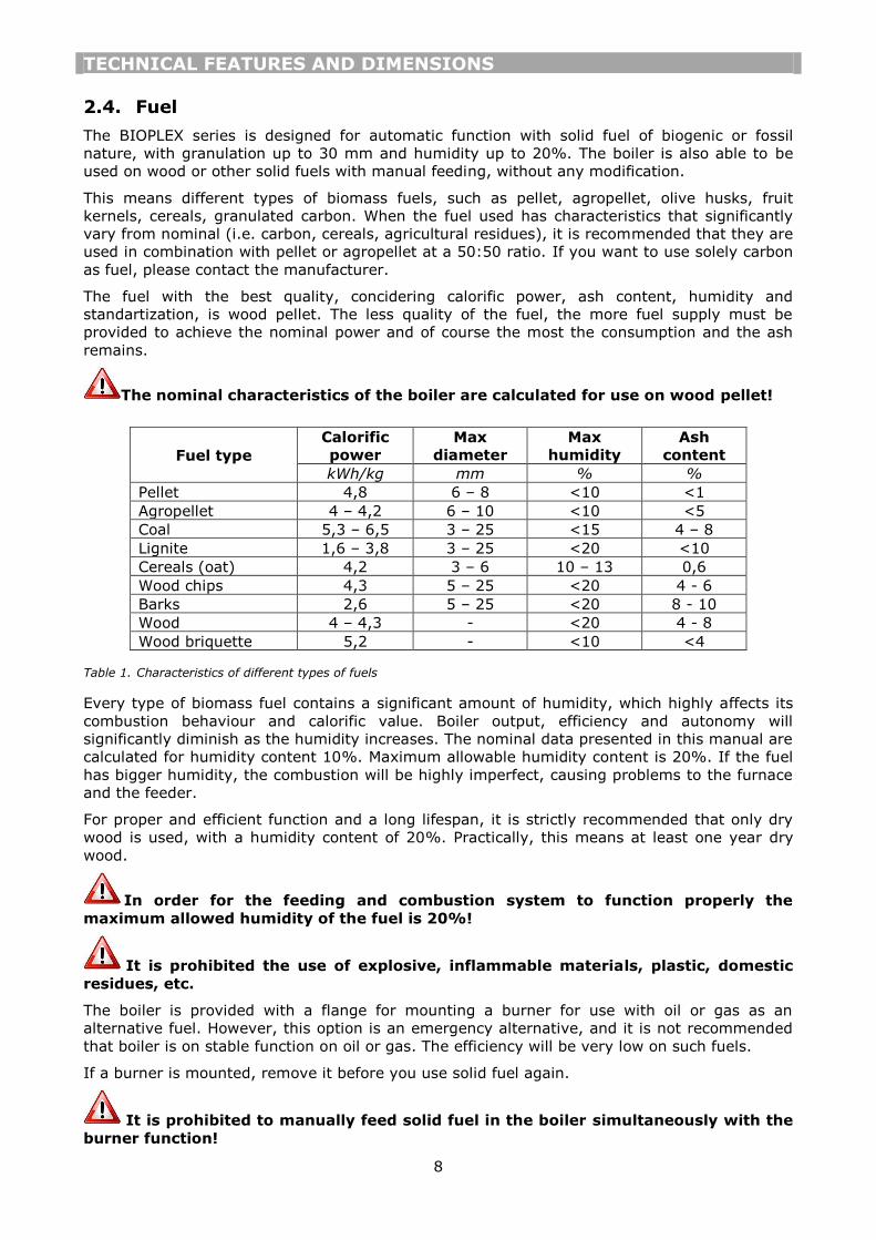
The nominal characteristics of the boiler are calculated for use on wood pellet!
Fuel type
Calorific
power
Max
diameter
Max
humidity
Ash
content
kWh/kg mm % %
Pellet 4,8 6 – 8 <10 <1
Agropellet 4 – 4,2 6 – 10 <10 <5
Coal 5,3 – 6,5 3 – 25 <15 4 – 8
Lignite 1,6 – 3,8 3 – 25 <20 <10
Cereals (oat) 4,2 3 – 6 10 – 13 0,6
Wood chips 4,3 5 – 25 <20 4 - 6
Barks 2,6 5 – 25 <20 8 - 10
Wood 4 – 4,3 - <20 4 - 8
Wood briquette 5,2 - <10 <4
Table 1. Characteristics of different types of fuels
Every type of biomass fuel contains a significant amount of humidity, which highly affects its
combustion behaviour and calorific value. Boiler output, efficiency and autonomy will
significantly diminish as the humidity increases. The nominal data presented in this manual are
calculated for humidity content 10%. Maximum allowable humidity content is 20%. If the fuel
has bigger humidity, the combustion will be highly imperfect, causing problems to the furnace
and the feeder.
For proper and efficient function and a long lifespan, it is strictly recommended that only dry
wood is used, with a humidity content of 20%. Practically, this means at least one year dry
wood.
In order for the feeding and combustion system to function properly the
maximum allowed humidity of the fuel is 20%!
It is prohibited the use of explosive, inflammable materials, plastic, domestic
residues, etc.
The boiler is provided with a flange for mounting a burner for use with oil or gas as an
alternative fuel. However, this option is an emergency alternative, and it is not recommended
that boiler is on stable function on oil or gas. The efficiency will be very low on such fuels.
If a burner is mounted, remove it before you use solid fuel again.
It is prohibited to manually feed solid fuel in the boiler simultaneously with the
burner function!

BOILER MOUNTING
9
3. BOILER MOUNTING
3.1. Transportation and delivery
The boiler is delivered on wood pallet, well positioned with metal plates. Remove them
carefully by unscrewinf the screws holding them in place.
The loading and unloading of the boiler must be performed with a forklift or a crane. A special
hook is provided on the upper part of the boiler for lifting.
The boiler is very heavy. Do not try to lift by hands or other unsuitable
equipment. Danger of injury! Perform all moves with extreme attention and care.
Remove the boiler packaging with attention. Keep the packaging material away from
chidren since it can be dangerous. After having unpacked everything, make sure that the
appliacne is intact and undamaged. In case of doubt do not use the appliance and inform the
supplier.
The BIOPLEX boiler is delivered with the following equipment already fitted and mounted:
Boiler steel body
Rockwool insulation mounted on the boiler body and tightened with plastic tapes
Metal covers mounted on the boiler body
Turbinators positioned inside the fire tubes
Cast iron catalyst for the biomass combustion
Cast iron grates for wood combustion
Control panel and electrical connections
The furnace system BIOFIRE is already preassembled and mounted on the boiler side flange. It
consists of:
BIOFIRE furnace steel body
Fuel silo with lid, shutter, inspection window
Feeder with screw
Fan
Motoreducer
Transmission system with chain wheels
Protection cover of the mechanism
Cast iron combustion plate
The following accessories are positioned inside the boiler body. Remove them carefully by
opening the middle door.
Cleaning tools
Safety kit
Drainage valve
In the documentation folder you will find:
Technical manual
Warranty leaflet
Declaration of conformity

BOILER MOUNTING
10
3.2. Boiler room
3.2.1. General requirements
The boiler must be installed in a special and separate room. This room must be chosen so that
it offers easy access for fuel transport, air supply and exhaust gas evacuation. The doors of the
boiler room must be metallic, open outwards, and have at least 0,9 m width.
The boiler installation is prohibited in rooms with extensive dust, dangerous
gases, and moist spaces.
For the correct boiler function it is necessary that the boiler room has openings for natural
ventilation and combustion air supply. It is recommended that two different openings are used
for this purpose, positioned on opposite walls and diagonally to ensure good air circulation. The
total surface of the openings must be at least 1/12 of the boiler room surface. Forced
ventilation is prohibited in the boiler room.
The boiler room must be provided with a drainage channel. All safety devices must be
connected to this channel.
The boiler room must have an appropriate fire extinguishing system, according to the
regulations in force. In case that the building is designed with a fire alarm system, a smoke
detector must be positioned on top of every boiler.
The fuel storage is prohibited in the boiler room. If so, the storage must be separated from the
boiler with a non-flammable wall, and proper distanced from the boiler.
3.2.2. Boiler room dimensions
The boiler must be placed on a horizontal plane, with
adequate mechanical resistance to support the boiler’s
weight. The boiler must be positioned in the room in such
a way so that it is easily accessible from all the sides. The
following dimensions are recommended (see Fig 2)
Distance from the front wall (N):
For boilers up to 100 kW – minimum 1,5 m
For boilers bigger than 100 kW – minimum 2 m
Distance from the rear wall (L):
Appropriate distance for maintenance access. Minimum
0,6 m.
Distance from side walls (M):
For boiler up to 300 KW – minimum 0,6 m
For boilers bigger than 300 kW – minimum 1 m
Boiler room height (H):
For boilers up to 70 kW – minimum 2 m
For boilers 70 to 230 kW – minimum 2,4 m
For boiler 230 to 400 kW – minimum 3 m
For boiler bigger than 400 kW – minimum 3,5 m
Distance between two boilers (P) must be at least 1m.
Fig 2. Boiler room dimensions

BOILER MOUNTING
11
3.3. Chimney
The chimney installation must supply sufficient draught, air tightness and protection against
condensation.
The appropriate chimney installation is very important for the boiler’s efficient
and safe function!
The chimney must be positioned if possible in the interior of the building. It must be vertical,
with no changes in the direction. The cross-section of the chimney can be round or
rectangular. If the chimney is installed in the exterior, it must be insulated.
The horizontal part connecting the boiler’s chimney pipe with the vertical chimney must have
maximum length 2 m. If this distance is bigger, it is recommended to have a 15-30o inclination
upwards. The connection with the boiler’s chimney pipe must be air-tight.
The chimney must be equipped with a cleaning door at its base. Also cleaning doors are
recommended where there are changes in direction and ash can be accumulated. Tactical
cleaning is recommended (every 3 months) for efficient boiler function.
A chimney terminal must be installed at the end of the chimney for protection against weather
effects and foreign objects entrance. In areas with strong winds a special anti-downdraught
terminal is recommended.
The chimney height must exceed the roofline by at least 1 m. If there are other obstacles
positioned on the roof, the chimney height must exceed them by at least 1 m. If there are
multiple chimneys, minimum distance between them is 0,3m.
Each boiler should be connected to an independent chimney. Connection of multiple boilers to
the same chimney is not recommended.
Fig 3. Chimney distances

BOILER MOUNTING
12
Fig 4. Chimney connection

INSTALLATION
13
4. INSTALLATION
4.1. Hydraulic connections
The boiler is intended for connection with an open expansion vessel network. The boiler can be
connected also with closed expansion vessel, if it is equipped with an overheating serpentine
(optional).
The boiler is intended for maximum working temperature 90oC and maximum pressure 3 bar
for boilers up to 500 kW, and 4 bar for bigger boilers.
When connected with a closed expansion vessel, its volume must be chosen double to a similar
installation on liquid or gas fuel.
If a connection pipe is not used, it must be sealed before water fill!
Legend
T1 Outlet
T2 Return
T3 Chimney pipe
T4 Discharge valve connection
T5 Safety kit connection
T6 Additional safety connection
4.2. Safety features
The boiler equipment includes a safety kit, which shall be connected to the corresponding
connection pipe T5. The kit consists of a safety valve, an air relief valve and a
thermomanometer. Bigger boilers are equipped with two or more safety valves.
Additional safety equipment can be mounted at the
connection pipe T6. This can be a dual safety valve
(pressure and temperature) or a cooling valve.
Alternatively this pipe can be used for connection
with the expansion vessel.
Fig 5. Boiler safety kit

INSTALLATION
14
4.3. Overheating serpentine
As an optional, the boiler can be equipped with an overheating protection serpentine. This is
incorporated in the boiler body, surrounding the fire chamber.
For the function of the safety serpentine, a discharge valve must be installed. The
bulb of the valve must be mounted on the boiler’s hot water delivery, at maximum distance
1m from the boiler.
Fig 6. Overheating serpentine connection
The valve can be connected on either side of the serpentine. Attention should be given to the
flow direction of the valve. The valve can be fitted on the cold water inlet or hot water outlet.
However, we recommend that the valve is fitted on the cold water inlet.
For the protection of the valve, a filter is recommended to be installed on the water line before
the valve.
On the opposite side of the serpentine, drainage must be connected.
The correct function of the discharge valve is crucial for the boiler’s safety.
Verify its function often and replace if defect.
4.4. Return temperature protection
For the correct function of the boiler and for protection against corrosion it is very important to
ensure steady temperature at the return of the boiler of at least 55oC.
This can be ensured by installing a recirculation pump between the boiler outlet and return
(see connection diagrams).
An alternative variation is by installing at the return of the boiler a three-way thermostatic
valve.

INSTALLATION
15
4.5. Filling the system
After completing all the hydraulic connections, the circuit may be filled with water. After filling
the system, open the radiators air valves to get rid of the air in the installation.
Verify that the installation pressure is according to the technical feature of the boiler. The
pressure must be verified through the boiler’s manometer. An additional manometer should be
installed on the cold water inlet to verify the cold pressure, at the lowest point of the
installation, at a point close to the boiler.
The whole installation must remain under nominal pressure for at least 10 minutes. During this
period, check that all the connections are tight and there are no water leakages. Make sure
that during this period no pressure drop appears.
After firing the boiler, make sure the network functions properly at working temperature and
pressure.
The hardness of the mains water supply affects the boiler’s life span. It is
recommended to use a water softener if water hardness exceeds 15of.
Do not fill the system at the working pressure! When the boiler will be heated,
the water pressure will raise. Filling pressure must be at least 1 bar lower than
working pressure!
4.6. Automatic ignition system
As an optional, the furnace can be provided with an automatic ignition system. This consists of
the following:
Ignition element 500W (2 pieces in bigger boilers)
Control panel Ecomax 800P (technical manual given with the control panel)
Exhaust temperature sensor
The ignition element is installed in a special inox tube casing, positioned under the furnace cast
iron plate. The cables are protected with a silicon layer, resistant to temperature up to 300oC.
All the electrical connections are prewired.
The controller is equipped with an exhaust temperature sensor. This must be installed on the
chimney, at a distance maximum 1m from the boiler.
If the boiler comes with the automatic ignition system, refer to the controller’s
manual for electrical connections and settings.

INSTALLATION
16
4.7. Connection diagrams
4.7.1. Open expansion vessel connection
Legend
1-9. Separation valves
10,11. Radiator valves
12. Radiators
13-15. Safety valves
16. Filling valve
17. Drainage valve
18. Cold water valve
19-24. One-way valves
B Hot water boiler
VED Open expansion vessel
PCI Central heating pump
PRC Recirculation pump
RP Pressure reducer
F Filter
A Air relief valve
FD Water softener

INSTALLATION
17
4.7.2. Closed expansion vessel connection
Legenda
1-9. Separation valves
10,11. Radiator valves
12. Radiators
13-15. Safety valves
16. Filling valve
17. Drainage valve
18. Cold water valve
19-24. One-way valves
B Hot water boiler
VE Closed expansion vessel
PCI Central heating pump
PRC Recirculation pump
RP Pressure reducer
F Filter
A Air relief valve
FD Water softener

BOILER START-UP
18
5. ELECTRICAL CONNECTIONS
5.1. General instructions
All electrical connection must be performed by an authorized professional, in conformity with
the local regulations and the indications of this manual. Connections must be done according
to norms EN 60529 and EN 60335-1, and protection norms IP 40 and IP 44.
All wiring must be waterproof insulated. Exposed cables should be protected within plastic
channel. The main electrical supply of the boiler must be connected to an independent safety
of max 16A. The boiler room lighting must be on a separate circuit.
THERMOSTAHL is not responsible for accidents or malfunctions caused by
wrong or bad electrical connections.
5.2. Control panel functions
Fig 7. Control panel
The general switch ON/OFF interrupts the electrical supply to all the devices.
The furnace thermostat interrupts the fan and motor function when the preset boiler
temperature has been reached. It is recommended that this temperature is set between 70-
90oC. This temperature should never be set below 60oC.
The fan speed regulator regulates the fan rotating speed by means of a dimmer rheostat.
The pump thermostat starts the circulation pump function at the preset temperature. It is
recommended that this temperature is set around 45-55oC. The pump indication lamp follows
the function of pump.
The safety thermostat will interrupt the fan function if the boiler temperature reaches above
95oC. If so, it needs to be reset manually by unscrewing the plastic cover.
The ventilator and motor switches are used to activate or deactivate the corresponding
devices. The switch has an incorporated indication lamp that follows the function of the
devices.
The motor timer controls the motor function by means of ON/OFF time intervals. The first
timer T1 controls the TIME OFF interval, while the T2 the TIME ON interval.
If a burner is connected to the control panel, it can be connected in the place of the fan and
regulated by the fan thermostat.
Legend:
1. Thermometer
2. Furnace thermostat
3. Safety thermostat
4. Pump thermostat
5. General ON/OFF switch
6. Motor timer
7. Fan speed regulator
8. Pump indication lamp
9. Motor switch
10. Fan switch

BOILER START-UP
19
The control panel offers the possibility to connect with a room thermostat. When the room
thermostat contact opens, the furnace function stops.
5.3. Wiring diagram
Fig 8. Control panel wiring diagram
Legend:
GS General ON/OFF switch
TS Safety thermostat
TM Furnace thermostat
TP Pump thermostat
VT Fan speed regulator
LP Pump indication lamp
SM Motor switch
SV Fan switch
TR Room thermostat
PE Grounding
Unscrew the control panel back plate to have access to the connection terminals in the interior.
Connect the main electrical supply to the terminals 1,2,3 as indicated. The fan is connected to
the terminals 10,11,12 and the pump to the terminals 4,5,6.
The motor phase is connected to the terminal 9, while neutral and grounding together with the
fan’s at terminals 12 and 11 respectively.
Between the terminals 7,8 there is a jumper. If you want to connect a room thermostat,
remove the jumper and connect it to these two terminals.
Attention: The room thermostat must be a simple contact interruptor. It is not
allowed to connect a digital thermostat with an electrical signal output!

BOILER START-UP
20
6. BOILER START-UP
6.1. Initial lighting checks
Before you start the boiler, make the following checks:
Check that all the hydraulic connections and make sure they are tight. Make sure there is
no leakage or moisture on the pipes or other equipment.
Make sure that the connection with the chimney is air-tight and the chimney installation is
properly made.
Check that the controller bulbs are well inserted and secured in the boiler’s case.
Make sure that the pressure in the network is correct.
Check that the boiler pump and the central heating pumps function properly.
Make sure that the connection with the expansion vessel is correct and the expansion
volume is sufficient for the boiler. No valves should be installed between the boiler and the
expansion vessel.
Make sure the boiler’s separation valves are open.
Make sure that there is sufficient air supply and natural ventilation in the boiler room.
Do not store inflammable materials or fuel close to the boiler! Before you light
the boiler make sure the boiler room is clear and safe.
6.2. Start-up
To correctly start up the BIOPLEX boiler follow the next steps:
Make sure the silo is full with fuel.
Make sure the chimney damper is positioned in horizontal position (completely open).
Open the middle door (feeding door) to have visual supervision of the feeding procedure.
Turn the control panel on from the general switch and activate only the motor from the
corresponding switch. Keep the fan deactivated during this step.
Set the first timer T1 to maximum and the second T2 to zero, in order to fill the furnace
with fuel. Fill it until the fuel level reaches the cast iron plate and covers a small part of it.
Stop the motor function from the motor switch.
Using sheets of thin paper or other ignition material, light the fuel placed in the furnace.
Wait several minutes until the flame stabilizes and covers the entire plate surface.
Close the middle door of the boiler. Turn on the fan by the corresponding switch. During this
step the motor must remain deactivated.
When the flame is fully developed, activate both the motor and the fan. Set the furnace
thermostat to the required temperature.
Follow the instructions given in the chapter Combustion Regulation to correctly regulate the
combustion.
It is prohibited to light the boiler with inflammable or explosive liquids.
6.3. Checks to carry after initial start-up
During the first start-up you need to carefully check the air-tightness of all the connections,
especially the doors and the connection with the chimney.
Check that the thermostats function properly and devices operate accordingly. Wait for the
boiler to reach the preset temperature and make sure the fan stops properly and the flame
falls down.
Check the temperature and pressure rise in the network. Make sure it is according to the
indications. Check if there is any water leakage in the network.
After burning of the fuel is completed, check the situation inside the boiler. If the walls are too
black, it means that there is insufficient air supply. If there is condensation forming on the

BOILER START-UP
21
boiler walls, it means that the pump operation starts at a low temperature or the fuel has too
big humidity content. Make sure you set the pump according to the indications and you install
a return temperature protection system as indicated.
6.4. Fuel loading
In order to correct add fuel to the boiler follow the next steps:
Stop the fan function by turning the fan thermostat to zero. Wait 30 seconds for the fume to
exit the boiler.
Open the middle door slowly to avoid leakage of smoke. Load a sufficient amount of fuel.
Each loading should be regulated according to the boiler output and the heat demand.
Never load too much to fuel to fill all the fire chamber volume! Maximum fuel should be 70-
80% of the fire chamber volume.
Close the door and secure with the handle.
Start again the fan function by putting the thermostat to the preset temperature.
When loading fuel in the boiler do not throw them but position them carefully.
6.5. Combustion regulation
After completing the start-up procedure and closing the door, set the required temperature to
the furnace thermostat (noted “Motor Regul”). After the fan and motor are activated, have a
look at the quantity of fuel fed to the furnace and the shape of it on the cast iron plate.
The timer must be set in such a way, so that the quantity of fuel fed is stable to a level where
it makes a small hill over the plate, covering almost half of its surface (middle picture). If the
fuel accumulates covering all the plate surface (left picture), it means the feeding is too big
and must be reduced. If the level of the fuel is below the plate (right picture), it means the
feeding is too small and must be increased.
Fig 9. Fuel feeding regulation
The feeding depends on two parameters: the feeding time (timer T1) and the stop time (time
T2). When you want to increase the feeding, increase the feeding time and reduce the stop
time. When you want to reduce the feeding, reduce the feeding time and increase the stop
time. These two timers must be set together, and with not too big difference (the ratio
between TIME ON/TIME OFF must be between 0,5-0,9). This way you achieve a stable feeding
and fire in the furnace.
After regulating the feeding, observe the flame shape and color through the flange provided on
the middle door. The flame will have to occupy about two thirds of the fire chamber and quietly
lick the cylindrical heat exchanger. Its shape must be fully developed and with not too many
detachments at the flame end. Its color must be vivid orange-yellow, not too transparent.
The combustion quality is regulated through the air delivery. By positioning the fan damper
you regulate the air pressure and by the control panel speed regulator you regulate the fan

BOILER START-UP
22
speed. The combination of these two will result to the optimum air delivery in order to
accomplish perfect combustion.
GENERAL SUGGESTIONS
The flame needs to have reasonable dimensions and fill up the fire chamber as told.
The flame must not be too red (too low air supply).
The flame must not have big detachments and sparkles (too high air supply).
The flame must not be too small. If it is slow, easily influenced by air currents and the
chimney draught, it means that the air supply is too low.
The smoke at the chimney must be clear-grey. Black smoke means lack of air supply.
If too much ash and big coal pieces fall down to the ash box reduce the air supply.
The flame is too fast, dry, and might make a noise.
6.6. Chimney damper adjustment
The boiler chimney pipe is equipped with a damper.
This can be set in various positions to throttle the
exhaust gases.
At nominal function of the boiler this damper should
be normally open. Also it should always be at open
position at boiler start-up.
If the chimney draught is too big and the gases are
evacuated too fast, set this damper at a side
position by inserting the positioner at a different
hole.
If a burner is installed, it is recommended that the
damper is in completely closed position.
Fig 10. Chimney damper

SERVICE AND MAINTENANCE
23
7. SERVICE AND MAINTENANCE
7.1. Cleaning
7.1.1. Cleaning the boiler
Solid fuel boiler require regular cleaning in order to function properly and efficient. Cleaning
must be effected at least once a week. The boiler is equipped with three cleaning tools
appropriate for the cleaning procedure of the boiler, as shown in Fig 11.
Fig 11. Boiler cleaning tools
The boiler function must be stopped before cleaning! Make sure all the devices
are stopped, and the boiler has cooled down. It is strictly prohibited to clean the
boiler while in function!
Open the upper door to have access to the heat exchanger. Remove the turbinators from the
tubes, and clean the tubes with the appropriate tool. Afterwards clean the exterior surface of
the cylindrical heat exchanger with the exchanger cleaning tool, as shown in Fig 12. With the
same tool, scrape the ash and any other remains from the side walls of the boiler.
Fig 12. Cleaning of the heat exchanger
Open the lower door of the boiler and remove
the ash box. Empty all the containing ash.
With the ash cleaning tool you can scrape the
lower surface of the boiler for any residues of
ash.
The ash must be disposed in an
appropriate container! Do not throw the
ash together with the domestic garbage.
Be careful since ash might contain hot
particles, even long time after stop.
Fig 13. Removing the ash
Legend:
1. Tubes cleaning tool
2. Heat exchanger cleaning tool
3. Ash cleaning tool

SERVICE AND MAINTENANCE
24
7.1.2. Cleaning the chimney box
To ensure efficient and safe function of the boiler, you must
clean the chimney box from ash residues at least every 3
months.
The ash box is equipped with a cleaning door for this
purpose, as shown in Fig 14. In order to open the door,
unscrew the wing nuts, remove the washers and springs that
keep it in place.
Clean the interior of the chimney box and remove all the ash
and residues.
Put back the door the same way as removed.
The springs must not be omitted! They act as
safety in order of explosion of exhaust gases in the
chimney box.
Fig 14. Cleaning the chimney box
7.1.3. Cleaning the furnace
The furnace should be regularly cleaned according to the ash deposits, but not less than once a
week. To clean the furnace follow the next steps:
Stop the furnace function by the control panel and leave it to cool down completely.
Clean the surface of the cast iron plate from ashes and other deposits. Make sure the air
holes are clean and free from obstacles.
Clean the ashes and deposits at the perimeter around the plate.
After you turn on again the furnace, ensure the fuel feeding is performed freely and the fuel
is evenly distributed at the plate surface.
Check the function of the motoreducer and the fan. Clean from dust if needed.
7.2. Maintenance intervals
7.2.1. Daily maintenance
The pressure of the network must be daily verified to be within the allowed limits. Make sure
that all the safety devices and pumps function properly.
7.2.2. Weekly maintenance
The boiler must be cleaned every 3-4 days or at least once a week, depending on the ash
quantity accumulated on the boiler walls and in the heat exchanger. Cleaning procedure must
be performed according to the instruction given in the corresponding paragraph.
Check the quantity of ash accumulated in the ash box. The ash disposal can be performed
every 1-2 weeks, depending on the ash quantity formed.
7.2.3. Monthly maintenance
Check the doors and the sealing cord. Make sure the contact with the boiler is air-tight. If ash
has accumulated on the sealing cord, clean it.
Check the fan and make sure it functions properly. Clean from dust and check that the air
passage is clear of obstacles and dust.
Remove the turbinators from the heat exchanger and check their condition.
It is recommended that you clean the chimney box of the boiler and the chimney pipes at least
every 3-4 months, in order to assure efficient and safe function of the boiler.

SERVICE AND MAINTENANCE
25
7.3. Basic service procedures
7.3.1. Service after overheating
If overheating occurs, the safety valves of the boiler must open. If the boiler is equipped with
an overheating protection coil, cold water will enter the coil to protect the boiler.
Make sure the boiler pump is working. In case of blackout open all the valves of the system to
let hot water out of the boiler. In any case a blackout protection UPS is recommended to be
installed on the boiler pump.
If the chimney damper is not fully opened, put it in fully open position.
All safety devices must lead to drainage! After overheating, make sure that all the water from
the safety devices has drained, and the system has filled with cold water. Check the pressure
and the temperature of the boiler.
At overheating, the safety thermostat will activate, and cut electrical supply to the fan. In that
case, you need to manually reset the safety thermostat and put the system back in function.
Unscrew the plastic cover of the safety thermostat and press the switch. Put the plastic cover
back.
Verify the causes of the overheating! If it happens again, check the installation
and function of the pumps and safety devices!
7.3.2. Service after feeder blockage
If a blockage occurs to one of the feeders, you will have to remove the axes in order to clean
the feeding tubes. The same procedure is applicable at the annual maintenance procedure.
Before proceeding to any of the following steps, make sure the boiler function is
stopped, the boiler is cool, and it is disconnected from the electricity. Do not try to do
any works while the motor is working and the control panel is activated! Risk of
injury!
REMOVING THE UPPER AXIS
Remove the protection cover of the transmission system.
Remove the two gears from the axes by unscrewing the headless inserted screws keeping
them in place. You do not need to unmake the chain! Remove them all together with
the chain.
Unscrew the four nuts from the back side of the flange (see Fig 15)
Fig 15. Removing the upper axis flange

SERVICE AND MAINTENANCE
26
Remove the whole feeder together with the bearings and supporting disk (see Fig 16).
Fig 16. Removing the upper axis
When putting back together, it is absolutely necessary to put the rubber gasket at
its position!
REMOVING THE LOWER AXIS
Remove the protection cover of the transmission system.
Remove the two gears from the axes by unscrewing the headless inserted screws keeping
them in place. You do not need to unmake the chain! Remove them all together with
the chain.
Unscrew the four nuts keeping the motor in place and remove it (see Fig 17).
Fig 17. Removing the lower axis
Remove the support disk and the feeder.
When putting back together, it is absolutely necessary to put the rubber gasket at
its position!

SERVICE AND MAINTENANCE
27
7.3.3. Service after motor bolt breakage
The connection between the motoreducer and the
lower axis is realized through a protection bolt. This is
designed in such a way so that it breaks in case of
feeder blockage, to protect the motor from burning.
If this bolt breaks, follow these steps to replace it:
Remove the two gears from the axes by
unscrewing the headless inserted screws keeping
them in place. You do not need to unmake the
chain! Remove them all together with the chain.
Unscrew the nut and remove the broken bolt.
Introduce a new bolt M6x50 and tighten with the
nut from the other side.
Verify the causes of the breakage. If there is an
obstacle in the feeding pipe remove it.
Fig 18. Motor protection bolt replacement
7.3.4. Service after power blackout
In case there is a power blackout, it is absolutely necessary to perform some checks and take
some safety measures to avoid overheating. The solid fuel has all the time a certain amount of
fuel in the fire chamber, which will not stop burning immediately.
For safety reasons it is recommended you have installed a UPS with a battery,
which assures function of the boiler pump at least for 30 minutes.
Remove the amount of fuel that is still burning in the furnace. Due to power blackout, there
is risk of backfire to the silo.
Turn the control panel to OFF.
When the power is restored, turn on the control panel and make sure all the devices
function properly.
7.3.5. Replacement of the ignition element
In case you need to replace the ignition element follow the instructions:
Turn OFF the control panel and disconnect from electricity.
Disconnect the connection wires of the ignition element and loosen the plastic tap holding
them in place.
Remove the fan by unscrewing the four screws keeping it in place.
Remove the furnace plate. The ignition element is positioned inside the INOX tube casing.
Remove the ignition element from the tube and insert in position the new one.
When you position back the furnace plate, be careful to fix it correctly with the fixing tooth,
as shown on Fig 19.

SERVICE AND MAINTENANCE
28
Fig 19. Removing the ignition element
7.4. Maintenance after long stop
7.4.1. Maintenance of the boiler
It is necessary to perform a general maintenance and cleaning of the boiler after the heating
season. Clean thoroughly all the surfaces of the boiler as described in the corresponding
paragraph. Also clean the chimney box, and all the chimney parts where ash might be
deposited. After cleaning all the ash, empty the ash box and leave the boiler clean for the next
winter season.
After long stop of the boiler, before you put in function you need to perform the following
checks:
Check the condition of the electric cables and the sensors. Make sure they are not
damaged. Check that the thermometer indicates the correct temperature and all the
thermostats function properly. Make sure the bulbs are properly positioned in the case.
Make a general check of the chimney and make sure it is clean and free of obstacles.
Verify the pressure in the heating network and the boiler.
Do not empty the water of the boiler and the heating installation after the
heating season! It will corrupt all the installation and especially the boiler.
Check that all the valves are working properly. Replace them if necessary. Pay special
attention so that all the safety equipment of the boiler functions properly!
Make sure all the ball valves of the boiler and other relative equipment are open.
Check the function of the pumps. They might be blocked after long stop.
Check that there have been no modifications to the installation and the boiler room
(ventilation openings, chimney, doors).
Check the fan and clean from dust. Turn it manually to ensure it is not blocked.
SERVICE AND MAINTENANCE
29
7.4.2. Maintenance of the furnace
It is necessary to perform a general maintenance and cleaning of the furnace after the heating
season. The maintenance of the furnace should only be done when the boiler is stopped, cool
and the power deactivated. For easier maintenance it is recommended to leave all the fuel in
the silo be consumed before you proceed to works. The maintenance procedure includes the
following steps:
Do not attempt to do any maintenance or service to the furnace while working!
There is serious danger of burning! Wait until the boiler is cool and deactivate from
the electricity.
Make sure the silo is empty. If not, empty manually the silo before proceeding to any
works. Open the silo cleaning door if necessary to remove any remaining fuel.
Remove the silo from the furnace body by unscrewing the bolts.
Remove the motoreducer which is mounted on the lower axis. See instruction in chapter
7.3.2.
Check the motoreducer. Check the oil level in the reducer and add oil if necessary.
Remove the two feeders. Check them and make sure they are in good shape and not
deformed.
Clean the tubes where the feeders are inserted. Remove any fuel or ash remains.
Remove the cast iron plate of the furnace.
Clean thoroughly the elbow underneath the plate, form where the fuel is provided. It is very
important to be clean of any obstacles that could block the feeding.
Clean very well all the holes on the plate surface. If they are blocked use a sharp tool to
clean them.
Put together all the pieces in the reverse order. Check all the sealing material between the
connections. Make sure they are in good shape and provide an air-tight sealing. Tighten well
the screws to ensure an air-tight connection.
After putting together the axes and the chain wheels, make the chain has a good grip on
the wheels and the rotation is performed freely. Grease carefully the chain and the wheels.
Attention: All the connections (boiler-furnace, furnace-silo, inspection doors,
etc.) must be air tight! If not there is high danger of backfire to the silo!

WARRANTY
30
8. TROUBLESHOOTING
Problem Cause Solution
The lamps of the
control panel do not
light
- no electrical supply to the lamp
- the control panel is not connected
to electricity
- lamp defect
- electric cable defect
- check/replace the lamp
- connect to electricity
- check/replace the cables
The boiler does not
reach set
temperature
- fan blocked
- air passages are blocked
- boiler is not cleaned
- incorrect boiler start-up
- insufficient water in the system
- too big pump debit
- boiler under dimensioned
- bad quality fuel used
- insufficient chimney draught
- check/replace the fan, check the
function of the fan regulator and
thermostat
- clean the air passages
- clean the boiler
- start the boiler correctly
- fill the system
- regulate the pump speed
- change the fuel used
- check/clean the chimney
High temperature in
the boiler, but low
temperature at the
radiators
- too high hydraulic resistance in the
heating network
- thermostatic mixing valve is
connected wrong
- increase the pump speed
- check/replace the mixing valve
Condensation
formation in the fire
chamber
- too big boiler power
- too low return temperature in the
boiler
- fuel with excessive humidity
- load less fuel in the chamber
- install a return protection
system/thermostatic valve
- change the fuel used
Smoke coming out of
the doors
- boiler doors not regulated
- defect sealing cord of the door
- insufficient chimney draught
- too high air supply by the fan
- regulate the doors so that the
sealing cord stays tight
- check/replace the sealing cord
- check/clean the chimney
- reduce the air speed
Smoke coming back
to the silo
- chimney not cleaned/blocked
- fire tubes blocked, boiler not
cleaned
- furnace air holes blocked
- insufficient air supply and
ventilation of the boiler room
- too low flame and fuel level
- bad air regulation
- wrong fuel ignition
- bad chimney connection/
insufficient chimney draught
- damaged sealing
- check the chimney, clean it
- clean the boiler and the tubes
- clean the furnace and the air
holes
- check the air supply and
ventilation
- regulate correctly the fuel feeding
- check the ignition procedure
- check the chimney connection
and draught
- check all the connections sealing,
do not leave the silo lid open
while in function
The fan does not
function or it makes
a lot of noise
- set temperature reached
- disconnected by safety thermostat
- capacitor/motor defect
- bad electrical connection of the fan
- correct boiler function
- reset manually
- check/replace the fan
- check the electrical connection of
the fan
The feeder does not
function/fuel not fed
to the furnace
- feeder blocked from obstacle
- feeder is burnt or damaged
- no electricity to motor
- damaged motor/reducer
- connection pin broken
- remove the axes and the
obstacle
- bad combustion regulation/bad
chimney draught
- replace feeder
- check the electrical connections
-replace the motoreducer
- replace the connection pin

WARRANTY
31
9. WARRANTY
1. Warranty duration is 3 years for all boiler parts under pressure, 1 year for other
electro-mechanical equipment. The warranty period starts from the date of installation,
but no longer than 120 days from the day of purchase.
2. The warranty covers costs of replacing parts that have been proved to be defect, and any
work that is connected with replacing these parts. Costs related to removing defect parts or
products, transportation, etc. are not covered by the producer’s warranty.
3. The producer will not accept to cover warranty terms in case of the following:
Maltreating the product and bad conditions of transportation and loading-unloading.
Wrong installation, failing to apply the directions given in the manual.
Improper use of the product.
Damages that have been cause by using improper fuels, with dimensions or
characteristics different from those described in the manual.
Damages from freezing if not necessary measures are taken against anti-freezing.
Incident of explosion due to use of impropriate chemical substances.
Electrical shocks that may harm electrical parts of the appliance.
4. Warranty is only valid if the installation is performed by a professional installer, authorized
by the producer, according to the local legislation and the instructions of this manual.
5. Warranty does not cover function problems or damages that are caused by bad chimney
installation, failing to respect the instruction of this manual and local legislation.
6. Warranty is not valid if the boiler cleaning, maintenance and service intervals are not
respected and the directions given are not followed.
7. Warranty is not valid if the maintenance is not performed by an authorized professional
according the instructions given and at the time intervals given.
8. Warranty does not cover costs related to emergency incidents like: earthquake, fire,
electrical blackout, robbery.
9. Warranty is not valid if the hardness of the water is over the allowed limits and no water
softening protection is installed.
10. The warranty is not transferable in case of reselling or replacing the product. A new
warranty should be accorded to the new user.

THERMOSTAHL ROMANIA
SISTEME TERMICE S.R.L.
DRUMUL OSIEI 57-59, sector 6
Bucharest 062395, Romania
www.thermostahl.ro