BIOMASS BOILER ATTACK® PELLET 30 · 2019-08-20 · 6 EN BOILER REGULATION The ATTACK PELLET 30...
40
BIOMASS BOILER ATTACK® PELLET 30 AUTOMATIC PLUS INSTRUCTIONS FOR USE WWW.ATTACK.SK
Transcript of BIOMASS BOILER ATTACK® PELLET 30 · 2019-08-20 · 6 EN BOILER REGULATION The ATTACK PELLET 30...
BIOMASS BOILERATTACK® PELLET 30
AUTOMATIC PLUS
INSTRUCTIONS FOR USE
W W W . A T T A C K . S K

2
EN
CONTENTS Important information: .............................................................................................................................................. 3�
Contents .......................................................................................................................................................................... 2�
Introduction: .................................................................................................................................................................. 3�
General description ..................................................................................................................................................... 4�
Purpose of usage .......................................................................................................................................................... 5�
Boiler description ......................................................................................................................................................... 5�
Boiler regulation ........................................................................................................................................................... 6�
Technical parameters .................................................................................................................................................. 6�
Dimensions of boiler ATTACK PELLET 30 AUTOMATIC Plus .......................................................................... 7�
Main parts of boiler ATTACK PELLET 30 AUTOMATIC Plus ............................................................................. 7�
Assembly and installation of boiler ........................................................................................................................ 8�
Boiler connection scheme ...................................................................................................................................... 10�
Burner connection scheme .................................................................................................................................... 11�
Boiler protection against corrosion .................................................................................................................... 12�
Binding norms for boiler projecting and assembly: ...................................................................................... 12�
Operation prescriptions .......................................................................................................................................... 13�
Maintenance of heating system with boiler .................................................................................................... 15�
Recommended schemes of connection ............................................................................................................ 16�
Technical description of burner ........................................................................................................................... 16�
Technical data of burner ......................................................................................................................................... 17�
Voltage and energy consumption of burner ................................................................................................... 17�
Description of burner function ............................................................................................................................. 18�
Usage of pellet burner ............................................................................................................................................. 19�
Menu buttons nad their function ........................................................................................................................ 19�
Messages on display ................................................................................................................................................ 20�
Menu messages ......................................................................................................................................................... 21�
Production settings .................................................................................................................................................. 22�
How to install pellet feeder and container ....................................................................................................... 25�
Burner start .................................................................................................................................................................. 25�
Burner shut down...................................................................................................................................................... 25�
Emergency shut down............................................................................................................................................. 26�
Cleaning and maintenance .................................................................................................................................... 26�
Troubleshooting ........................................................................................................................................................ 27�
Possible causes of faults .......................................................................................................................................... 28�
Accessories .................................................................................................................................................................. 29�
Advanced menu ........................................................................................................................................................ 30�
Instructions to disposal of product after expiration of its lifetime ........................................................... 34�
Disposal of packaging ............................................................................................................................................. 34�
Accessories .................................................................................................................................................................. 34�
�
3
EN
IMPORTANT INFORMATION: Boiler for wood pellet combustion. Installation, test heat-up and training of attendance must be performed by trained service
technician, who has to fill-in the protocol about boiler installation. Recommended boiler operation temperature is 80 – 90°C. Lower operation temperature may
cause creation of condensate, shorter life-time of boiler and warranty expiration. The only fuel to use are pellets, adequate to the approved fuel specification. Appropriate boiler output represents very important condition of economic operation and
correct boiler function. Nominal boiler output has to be adequate to thermal losses of the heated object.
It is the responsibility of the installer to ensure compliance to all relevant building regulations. Please, read this manual before starting-up the boiler. Keep this manual for attendance on a suitable place in the boiler room. It is recommended to
keep it in a plastic pack and to hang it on a visible place on the wall to be reached by techni-cian, when doing service in your boiler room.
Boiler door and connections between boiler and chimney have to be airtight. Overpressure in combustion chamber should be at least 5 pascal (0,5 mm of water column,
resp. 0,05 hPa). The PEL30AP appliance is intended for combustion of wood pellets and it cannot be used for
combustion of other fuel types. The PEL30AP appliance for pellet combustion can be installed in a boiler room only, in con-
formity with prescriptions of the local fire safety / construction authority. WARRANTY FOR BOILER IS NOT VALID IF: it is not operated with prescribed fuel - pellets adequate to the approved fuel specifica-
tion. there is no mixing device Regumat ATTACK-OVENTROP installed in the system to en-
sure temperature of the boiler return water over 65°C.
WARNING SIGN Warning sign is used in this manual to prevent potential hazards by breaking the instructions. Two types of warnings are used in this manual:
WARNING – warns about dangerous situations and situations that may cause health inju-ry or damage by breaking the indespansable measures.
ATTENTION – warns about less dangerous procedures that may cause safety hazard or damage of property.
4
EN
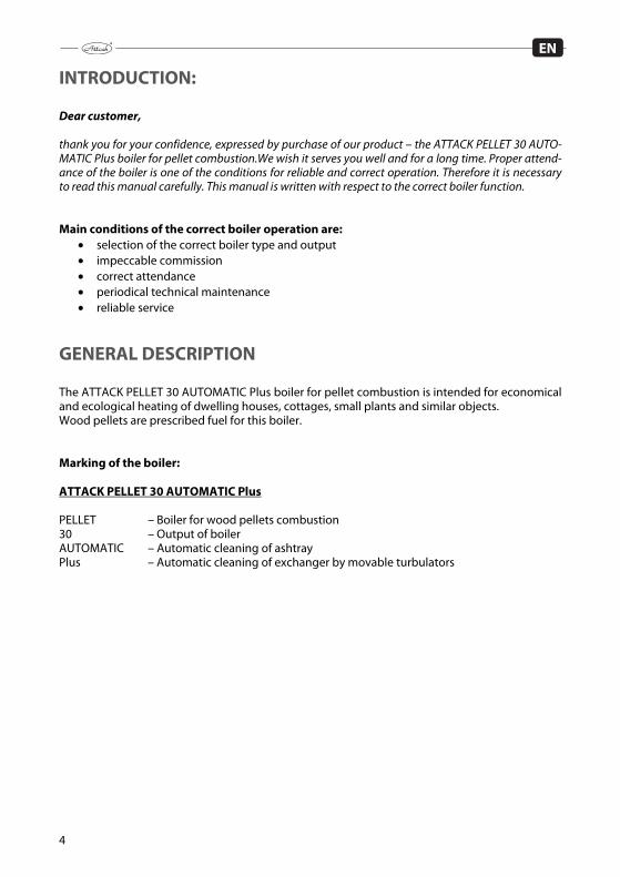
INTRODUCTION: Dear customer, thank you for your confidence, expressed by purchase of our product – the ATTACK PELLET 30 AUTO-MATIC Plus boiler for pellet combustion.We wish it serves you well and for a long time. Proper attend-ance of the boiler is one of the conditions for reliable and correct operation. Therefore it is necessary to read this manual carefully. This manual is written with respect to the correct boiler function. Main conditions of the correct boiler operation are:
selection of the correct boiler type and output impeccable commission correct attendance periodical technical maintenance reliable service
GENERAL DESCRIPTION The ATTACK PELLET 30 AUTOMATIC Plus boiler for pellet combustion is intended for economical and ecological heating of dwelling houses, cottages, small plants and similar objects. Wood pellets are prescribed fuel for this boiler. Marking of the boiler: ATTACK PELLET 30 AUTOMATIC Plus PELLET – Boiler for wood pellets combustion 30 – Output of boiler AUTOMATIC – Automatic cleaning of ashtray Plus – Automatic cleaning of exchanger by movable turbulators
5
EN
PURPOSE OF USAGE The ATTACK PELLET is a modern boiler for wood pellet combustion. By its technology it saves environment and offers comfort comparable with usage of gas boiler. Boiler is intended for heating of family houses, shops, industrial objects and other similar build-ings.
BOILER DESCRIPTION The ATTACK PELLET 30 AUTOMATIC Plus boiler burns pellets with diameter of 6 – 8 mm and max. length of 35 mm. Construction of boiler is consists from combustion chamber with partition, heat exchanger and flue connection. Boiler body cooled by water is a basic part of boiler. It is welded from boiler steel plates of 3–6 mm thickness to ensure long lifetime. Tubular exchanger is equipped with turbulators, ensur-ing better heat transpher into heating water. They also serve for exchanger cleaning to provide uniform efficiency. Combustion takes place in the burner. Optimal conditions for burning and output regulation are ensured electronically, by controlling fuel and air supply, in dependence on the heating parame-ters required by user. Construction of burner, combustion chamber and exchanger ensures optimal burning of all combustible contents. Boiler is equipped with device for automatic ash removal from the bottom of combustion chamber into the external box. Ash removing is set by production for every 12 hours. Boiler body is insulated with mineral wool. Boiler covering is treated by powder technology. Boiler can be accessorized with device for fuel supply and with pellet hopper of 450 l. In case of fuel shortage or burner failure it is possible to use electrical coil up to the 6 kW output (and 450 mm length), installed into the flange with G 6/4” internal thread on the left side of boiler. This coil can be also used as an anti freeze protection. Coil is equipped with operating and emergency thermostat. Its electrical installation is independent from electrical installation of boiler.

6
EN
BOILER REGULATION The ATTACK PELLET 30 AUTOMATIC Plus boiler for pellet combustion is regulated by control panel placed on the upper covering. 1 – Main boiler switch – Plugs boiler into / off the power 2 – Burner mode switch – switches burner between stand-by and operating mode 3 – Boiler thermostat – setting of boiler operating temperature 4 – Thermomanometer 5 – Reset button of the emergency thermostat – under cover 6 – Fuse 10 A / 250 V Operation, parameters and settings of burner are described in the appendix of this manual.
TECHNICAL PARAMETERS Boiler type PELLET 30 AUTOMATIC Plus Boiler output kW 30 Output range kW 8 – 30 Heat exchange area m2 1,9 Prescribed chimney draught Pa 15 – 20 Max. operating water overpressure kPa 250 Pressure loss of water Pa 152 (ΔT=10K); 38 (ΔT=20K) Boiler weight kg 355 Flue diameter mm 150 Boiler height mm 1220 Boiler width mm 575 Boiler depth mm 1 250 Protection of el. parts IP IP 40 Max.el.input (by ignition) W 600 Operating el. input W 90 Boiler efficiency % 90,6 Boiler class by CO emission (under EN 303-5) 5 Flue temperature by nominal output °C 143 Prescribed fuel Wood pellets d=6 – 8 mm, l=35 mm max. Average consumption kgh-1 2,4 – 6,9 Volume of water in boiler l 62 Range for setting of heat. water temperature °C 60 – 90 Connection voltage V/Hz 230/50
Prescribed temperature of boiler return water within operation is 65°C. Recommended operating temperature of water in boiler is 80 – 90°C. The ATTACK, s.r.o. manufacturer reserves right for change of technical parameters and boiler dimensions without previ-ous announcement.
7
EN
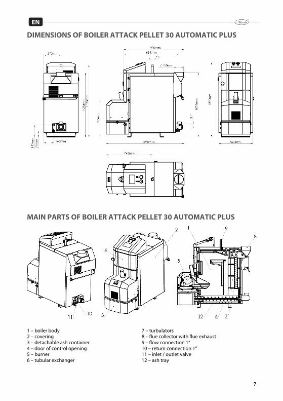
DIMENSIONS OF BOILER ATTACK PELLET 30 AUTOMATIC PLUS
MAIN PARTS OF BOILER ATTACK PELLET 30 AUTOMATIC PLUS
1 – boiler body 7 – turbulators 2 – covering 8 – flue collector with flue exhaust 3 – detachable ash container 9 – flow connection 1“ 4 – door of control opening 10 – return connection 1“ 5 – burner 11 – inlet / outlet valve 6 – tubular exchanger 12 – ash tray

8
EN
ASSEMBLY AND INSTALLATION OF BOILER Installation of boiler Only the person with valid approval for installation and assembly of the heat technology devices can install the boiler. For installation it is necessary to elaborate a project in conformity with the valid prescriptions. Technician must check, if information on data plate comply with project and accompanying documentation, before doing the installation. Boiler must be connected in con-formity with valid prescriptions, norms, regulations and this manual. Manufacturer takes no re-sponsibility for damages caused by incorrect connection, eventually by incorrect operation. Placing of boiler Boiler is intended for installation and operation in premises with elementary environment (AA5/AB5) under the STN 33 2000-3. By boiler installation it is necessary to keep safety distance of its surface from flammable materials in dependence on the grade of flammability: from materials of flammability B, C1, C2 200 mm from materials of flammability C3 400 mm from materials, which grade of flammability
has not been approved under the STN 73 0853 400 mm Examples of division of constructive materials by the grade of flammability: grade of flammability A – inflammable (brick, block, ceramic tiles, mortar, plaster) grade of flammability B – very difficult to ignite (heraclith, lignos, boards from bazart felt) grade of flammability C1 – hard flammable (beech, oak, plywood, wersalit, hardened paper) grade of flammability C2 – medium flammable (pine, spruce chipboard, solodur) grade of flammability C3 – lightly flammable (boards from wood fibres, polyurethane, PVC,
foam rubber, polystyrene) If boiler stands on the floor from flammable materials, it must be protected by inflammable heat insulating pad, excessing boiler edge for 150 mm at least. It is possible to use materials of the flammable grade A as inflammable and heat insulating mate-rials. Any items from flammable materials cannot be placed on the boiler and in distance shorter than 500 mm. When placing boiler in the boiler room, there should be free space left of at least 1 m beyond and 0,5 m from the sides and rear part of boiler. Above the boiler, there should be free space of at least 1 m. This space is necessary for ordinary operation, maintenance and eventual boiler servicing.
ATTENTION: It is inadmissible to place the ATTACK PELLET 30 AUTOMATIC Plus boiler in dwelling premises (including corridors)!
Air inlet For correct boiler operation, it is necessary to ensure sufficient air supply for combustion. Mini-mum area of the air inlet is 200 cm2. Boiler connection into heating system Installation and service of the ATTACK PELLET 30 AUTOMATIC Plus boiler can be performed by trained service technician only. Before boiler installation into the older heating system, it is nec-essary to flush the whole system to clean it. Heating system must be filled with water fulfilling requirements of the STN 07 7401:1991 and its callosity cannot exceed 1 mmol/l and concentra-tion Ca2+ 0,3 mmol/l. By unkeeping these conditions, warranty for boiler expires!
9
EN
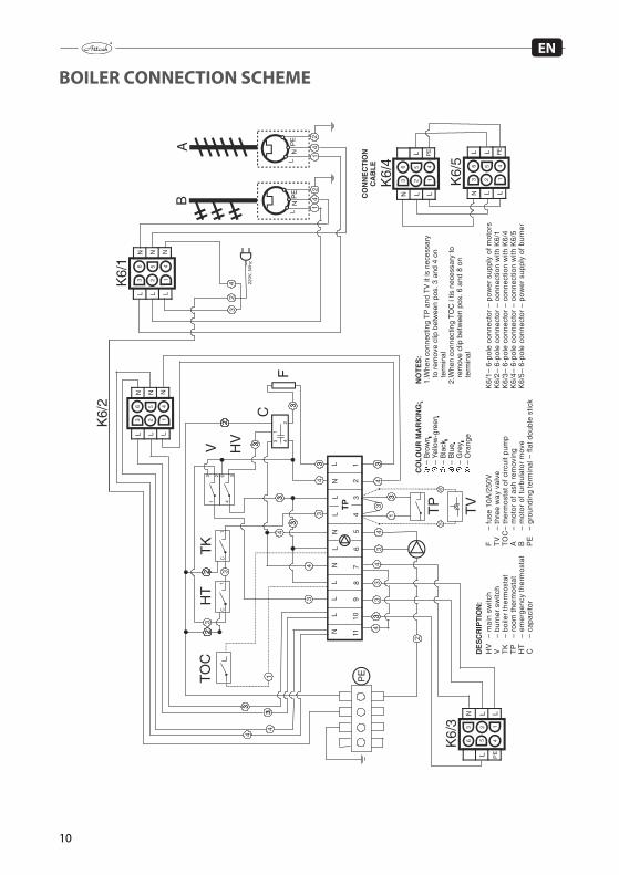
Selection and way of connection of regulation and control elements Boiler is delivered with basic regulation and control equipment. Connection of these elements is given on connection scheme. It is recommended to extended boiler regulation for next regula-tion elements for more comfortable and economical operation. Every pump in the system must be controlled by individual thermostat to prevent boiler undercooling at the return water inlet (return connection) under 65°C. Connection of these elements is proposed by projectant, following specifical conditions of heat-ing system. Electrical installation in combination with sufficient boiler equipment must be done by specialist under the valid norms. Connection to electricity mains Boiler is connected to el. mains 230 V / 50 Hz by plug with fork. Plug of M type has to be replaced by service technician with the same type of plug. Appliance must be placed in the way enabling attendance to reach the connection fork (under the STN EN 60335-1+A11:1997). Connection of el. socket must be in conformity with the STN 33 2000-4-46 norm. Socket must be equipped with middle protection stick, connected to the PE conductor. It is not permitted to use different cable distributors and extensions. Due to safety, power inlet must be freely accessible, when being connected to the el. mains. Flue connection Flue connection must empty into chimney vent. If it is not possible to connect boiler to chimney vent directly, appropriate extension of flue should be as short as possible (not longer than 1 m), without additional heating area and it has to ascend in direction towards chimney. Extensions of flue connection must be mechanically firmly joined, tight against flue leakage and easily cleana-ble. Extensions of flue connection cannot lead through foreign dwelling or utility units. It is nec-essary to eliminate usage of elbows and horizontal parts. Chimney Connection of appliance to chimney vent must always be done with agreement of the appropri-ate chimney authority. Chimney vent must create sufficient draught and reliably exhaust flue into atmosphere under all practically possible conditions. Correct dize of the chimney vent en-sures correct boiler function. Chimney draught directly depends on its diameter, height and roughness of its internal wall. Chimney vent must be sufficiently insulated to prevent creation of condensate. Temperature of the area of 1 m under the chimney collar cannot be lower than 60°C. Any other appliance cannot be connected to the chimney joined with the boiler. Diameter of chimney cannot be smaller than boiler outlet. Chimney draught must achieve prescribed val-ues. However, it cannot be too high, not to decrease boiler efficiency and not affect the combus-tion (not to disturb the flame). In case of too strong draught i tis necessary to install throttling flap between boiler and chimney. Information values of chimney diameter 20 x 20 cm min. height 7 m 20 cm min. height 8 m 15 x 15 cm min. height 11 m 16 cm min. height 12 m Exact chimney dimension is determined by the STN 73 42 10. Prescribed chimney draught is giv-en in the Technical parameters.
10
EN
BOILER CONNECTION SCHEME
NN
NL
1110
98
76
54
32
1T
P
334
133
4
TP
433
33
4
33 31
33F
C
TK
HT
13 2
456
C1
C1
V HV 4
2
33
TO
C
1
3
CO
LO
UR
MA
RK
ING
:
�
– B
row
n –
Yel
low
-gre
en
�
– B
lack
�
– B
lue
�
– G
rey
� –
Ora
nge
�
DE
SC
RIP
TIO
N:
56
TV
K6/
3
PE
N
123
456
AB
33
123
456N
PE
K6/
5
123
456N
PE
N
CO
NN
EC
TIO
NC
AB
LE
34 22
0V, 5
0hz
33
433
4
42
42
4
123
456N N N
123
456N N N
PE
K6/
2K
6 /1
4
4
NO
TE
S:
1. W
hen
conn
ectin
g T
P a
nd T
V it
is n
eces
sary
to
rem
ove
clip
bet
wee
n po
s. 3
and
4 o
n te
rmin
al2.
Whe
n co
nnec
ting
TO
C i
tis n
eces
sary
to
rem
ove
clip
bet
wee
n po
s. 6
and
8 o
n te
rmin
al
LL
LL
LL
L L
L
L L L
L
L
33
3
3
3
3
3
L L
11
L
L
L L
L LH
V
– m
ain
switc
hV
–
bu
rner
sw
itch
TK
–
boile
r th
erm
osta
tT
P
– ro
om t
herm
osta
tH
T
– em
erge
ncy
ther
mos
tat
C
– ca
pac
itor
F
– fu
se 1
0A
/25
0V
TV
–
thre
e w
ay
valv
eT
OC
– th
erm
ost
at o
f ci
rcui
t pum
pA
–
mot
or
of a
sh r
emov
ing
B
– m
otor
of t
urbu
lato
r m
ove
PE
–
grou
ndin
g te
rmin
al –
fla
t dou
ble
stic
k
K6/
1 –
6-po
le c
onne
ctor
– p
ower
sup
ply
of m
otor
sK
6/2
– 6
-po
le c
on
ne
ctor
– c
on
ne
ctio
n w
ith K
6/1
K6/
3 –
6-p
ole
co
nn
ect
or –
co
nn
ect
ion
with
K6/
4K
6/4
– 6
-po
le c
on
ne
ctor
– c
on
ne
ctio
n w
ith K
6/5
K6/
5 –
6-po
le c
onne
ctor
– p
ower
sup
ply
of b
urne
r

11
EN
BURNER CONNECTION SCHEME
1
L L L L LL N N N N * *
3
2 3 4 5 6 7 8 9 12 13 PE 15 16
033
N L
+ -
EK
M
0EK
025EK025EK
EK027
1
2
4
5
11
16
15
17
13
14
12
8 6
10 9
*
F1 F2F3
F5
L
1 – Basic electronics2 – Display electronics3 – Electronics of cleaning4 – Display5 – Data cable6 – Feeder7 – Motor of ash removing8 – Socket for feeder9 – Ventilator10 – Sensor of ventilator rotations11 – Gear of cleaning12 – Boiler temperature sensor13 – Photocell14 – Coil15 – End–switch16 – Thermal fuse17 – Connector
F1 F800mAL250V – – Ventilator F1AL250V F2 – – Pellet feeder T6 3AL250V F3 – – Ignition F800mAL250V F5 – – Gear of ash removing
– Contact without potential
L1 L2
L3PE
N
N
1 2 3
4 5 6
1
2
3
4
1
2
3
4
1
2
3
4
1
2
3
4
COLOUR MARKING: – Black�
– Blue�
– Yellow–green�
CONNECTIONCABLE
12
EN
BOILER PROTECTION AGAINST CORROSION Suitable solution of this problem is usage of the mixing device Regumat Attack-Oventrop). This solution enables creation of separate boiler and heating circuit and prevention against boiler undercooling under 65°C. Thereby it comes to decrease of water steams condensation and acid and tar creation in boiler exchanger and combustion chamber. Usage of device is a condition of the valid warranty. Regumat serves to keep temperature of the return heating water flowing into the boiler over 65°C, when thermostatic head is set to the 5 – 6th grade. Temperature of 60°C in the return connection causes increased creation of condensate and tar and consequently, shorter lifetime of boiler. Technical parameters: Clearance DN25 Max.pressure 10 bar Max.temperature 120°C Value kvs 3,9 The Regumat consists of three way mixing valve, circuit pump, closing valve, thermometers and isolation. This solution is advantageous due to its compactness, easy attendance and guaranted protection of the boilers heat exchanger. Regumat for boiler ATTACK PELLET: ordering code - DPP25003
BINDING NORMS FOR BOILER PROJECTING AND ASSEMBLY: STN EN 303-5 Heating boilers for solid fuels STN 734210 Design of chimneys and flue exhausts STN 920300 Fire safety of local appliances and heat sources STN EN 60335-1+A11 safety of el. appliances for household STN 061000 Local appliances for solid, liquid and gaseous fuels STN 060310 Central heating projecting and assembly STN 060830 Safety device for central heating and DHW STN 077401 Water and steam for heat energy devices with operation pressure of
steam up to 8 MPa STN 33 2000 4-46 Electrical installations of buildings. Part 4: Ensuring safety. STN 33 2000-3 Electrical installations of buildings. Part 3: Determination of basic
characteristics STN 061008 Safety of heat devices STN EN ISO 11202 Acustics STN EN ISO 3746 Acustics STN EN 62233 Measuring methods of electromagnetic arrays of appliances for
household and similar devices by the exposition of persons STN ISO 80000 Measurements and units
13
EN
OPERATION PRESCRIPTIONS Boiler preparation for operation Before starting the boiler, make sure, that the system is filled with water, deareated and there is no pressure decrease of the heating water. Check tightness and construction of flue exhaust. To ensure quality function, the boiler must be attended in conformity with instructions given in this manual. Only adult person can operate the boiler. Boiler start-up Boiler is switched to the stand-by mode by the main switch (left button of double-switch), placed on the boiler control panel. This is signalized by red control light in the main switch. Boil-er is started by switching the burner mode switch on (right button of double switch). This is sig-nalized by control light in the switch. Knob of boiler thermostat has to be set to the required temperature of heating water. By clockwise turning the thermostat is the required temperature increased and vice versa. Fuel in the burner is ignited automatically by el. coil built inside. Boiler operation is automatic and it is controlled by boiler thermostat and other regulation elements, that can be connected into boiler terminal (e.g. room thermostat, programmable regulator, ...). Details about setting the burner parameters are described in the next chapters of this manual.
ATTENTION! Condensation and condensate leakage may occur by first heat-up. After longer heating, condesation is eliminated.
If the boiler was out of order for longer period (turned off or faulty), it is necessary to be more careful when starting it again. After longer idle period it may come to pump blockage or water leakage from system. Regular and proper cleaning is important to ensure sustainable output and boiler life-time. Poor cleaning may cause boiler damage. All boiler door have to be tightly closed during the opera-tion. Fuel By burners for wood pellets combustion: APPROVED FUEL SPECIFICATION Moulded wood pellets Measured weight: 600 – 750 kg/m3 Heat value: 4,7 – 5,0 kWh/kg Size/diameter: 6 – 8 mm Size/length: Attention! max. 35 mm Moisture max.: 12 % Ash content: 0,5 – 1 % Dust content: max. 3 % Ash smoulder temperature: min. 1 100°C Fuel must be in conformity with requirements of the norm DIN 51 731. Methods of boiler regulation Boiler regulation without room thermostat For this case there is interconnection installed on contacts of boiler electrical terminal (TP-U1/ U2). Boiler is regulated according to the boiler temperature set on the boiler thermostat placed on the boiler control panel.
14
EN
Boiler regulation with room thermostat Boiler is controlled by the room thermostat, connected to the terminal contacts (TP -L1/L2) in-stead of interconnection, that has to be removed. The required boiler temperature will be con-sidered as well. Also other type of requirement can be installed instead of the room thermostat – e.g. programmable regulator of heating.
ATTENTION! There is dangerous contact voltage of 230 V on the connection contacts of the room thermostat! Boiler must be disconnected from electricity by any action into the electrical terminal or boiler electrical installation!
Boiler protection Boiler is equipped with emergency thermostat. If the boiler temperature exceeds 110°C, boiler safely gets out of order. When the boiler temperature decreases, it is possible to start the boiler again by using the reset button placed on the front control panel. Fuel refill Fuel is refilled in the container that belongs to the optional boiler accessories. Fuel should be refilled before the pellets in the container are totally consumed.
ATTENTION! Fuel container can be open only when fuel is being refilled, eventually by cleaning. Container has to be closed during the boiler operation.
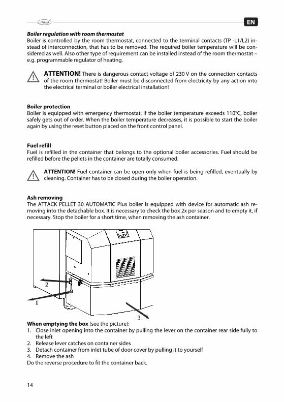
Ash removing The ATTACK PELLET 30 AUTOMATIC Plus boiler is equipped with device for automatic ash re-moving into the detachable box. It is necessary to check the box 2x per season and to empty it, if necessary. Stop the boiler for a short time, when removing the ash container.
1
2
3 When emptying the box (see the picture): 1. Close inlet opening into the container by pulling the lever on the container rear side fully to
the left 2. Release lever catches on container sides 3. Detach container from inlet tube of door cover by pulling it to yourself 4. Remove the ash Do the reverse procedure to fit the container back.
15
EN
When cleaning bottom of the combustion chamber, stop the boiler for a short time. Empty the iron ashtray, eventually – sweep the boiler bottom. Ash tray is placed in the bottom part of boil-er, behind the ash tray door. Use gloves by manipulation with ash tray to prevent burning your hands. When the ash is removed, it is necessary to put the ash tray back and to close the ash tray door tightly.
WARNING – Do not operate the boiler without the ash container fixed with the closed upper cover (possible flue leakage) – life safety hazard!
Short-time boiler stop If you wish to stop the boiler for a short time, turn the burner switch off and let the fuel burn down in the burner. Do not turn off the main switch. Long-time boiler stop When stopping the boiler for a long time, firstly – turn the burner switch off and let the fuel in the burner burn down. After the boiler is cooled down to 30°C, turn the main switch off and dis-connect the plug from power socket.
MAINTENANCE OF HEATING SYSTEM WITH BOILER At least 1x in 14 days it is necessary to check, eventually to refill water in the heating system.If the boiler is out of order during the winter, there is danger of water freezing in the system. Thereby it is reasonable to drain the water out. In other cases, drain the water out only, when it is absolutelly necessary and for as short period as possible. After the heating season it is necessary to clean the boiler properly (after long idle period, the ash has to be sweeped out from the con-tainer / ash tray, walls and bottom of combustion chamber have to be cleaned as well) and re-place the damaged parts. Exchange of the door sealing cord Remove the old sealing cord by screw driver and clean the groove, where the cord is placed. Take new cord and put its leading end between the horizontal parts of the groove. Use hand, eventually hammer to fit the cord into the groove along the door edge. Fitting the hinges After a particular period, it may come to abrasion of the sealing cord. To endure tightness of door, it is necessary to change their position by screwing the hinges. Inspection door is fixed to the boiler body by a long pin. Pull the pim out and screw the hinge by turning to change its po-sition. Fit the door and put the pin back into the hinge.
WARNING! To pull the pin of the upper door out, it is necessary to demount the upper boiler covering. To protect the health, the boiler has to be turned off and the plug has to be disconnected from electrical socket.
16
EN
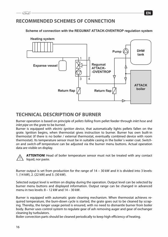
RECOMMENDED SCHEMES OF CONNECTION
TECHNICAL DESCRIPTION OF BURNER Burner operation is based on principle of pellets falling from pellet feeder through inlet hose and inlet pipe on the grate to be burned. Burner is equipped with electric ignition device, that automatically lights pellets fallen on the grate. Ignition begins, when thermostat gives instruction to burner. Burner has own built-in thermostat (if there is no boiler / external thermostat, eventually combined device with room thermostat). Its temperature sensor must be in suitable casing in the boiler´s water coat. Switch-on and switch-off temperature can be adjusted via the burner menu buttons. Actual operation data are visible on display.
ATTENTION! Head of boiler temperature sensor must not be treated with any contact liquid, nor paste.
Burner output is set from production for the range of 14 – 30 kW and it is divided into 3 levels: 1. (14 kW), 2. (22 kW) and 3. (30 kW). Selected output level is written on display during the operation. Output level can be selected by burner menu buttons and displayed information. Output range can be changed in advanced menu in two levels: 8 – 12 kW and 14 – 30 kW. Burner is equipped with automatic grate cleaning mechanism. When thermostat achieves re-quired temperature, the burn-down cycle is started, the grate goes out to be cleaned by scrap-ing. Thereby, the longer usage period is ensured, with no need to dismantle burner from boiler body. Burner uses control system to regulate gear of ash removing auger and gear of exchanger cleaning by turbulators. Boiler convection parts should be cleaned periodically to keep high efficiency of heating.
1 2
43
17
EN
Burner is intended for combustion of wood pellets with diameter of 6 – 8 mm. Burner is manufactured following the industrial norms and prescriptions and it was tested and approved in conformity with directives about low voltage devices and with directives about electromagnetic disturbance.
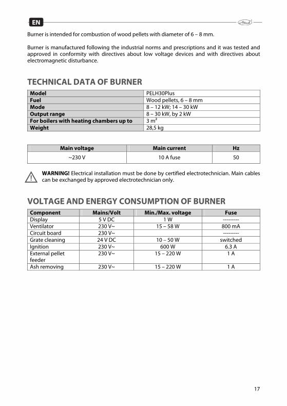
TECHNICAL DATA OF BURNER Model PELH30Plus Fuel Wood pellets, 6 – 8 mm Mode 8 – 12 kW; 14 – 30 kW Output range 8 – 30 kW, by 2 kW For boilers with heating chambers up to 3 m² Weight 28,5 kg
Main voltage Main current Hz
~230 V 10 A fuse 50
WARNING! Electrical installation must be done by certified electrotechnician. Main cables can be exchanged by approved electrotechnician only.
VOLTAGE AND ENERGY CONSUMPTION OF BURNER Component Mains/Volt Min./Max. voltage Fuse Display 5 V DC 1 W --------- Ventilator 230 V~ 15 – 58 W 800 mA Circuit board 230 V~ --------- Grate cleaning 24 V DC 10 – 50 W switched Ignition 230 V~ 600 W 6.3 A External pellet feeder
230 V~ 15 – 220 W 1 A
Ash removing 230 V~ 15 – 220 W 1 A

18
EN
DESCRIPTION OF BURNER FUNCTION
ATTENTION! Burner works with boiler thermostat only, eventually extended with room thermostat. In both cases it has to be connected through protection against boiler over-heating.
Normal start-up When thermostat gives instruction to burner, ventilator is started and photocell controls
flame. If there is no flame, then comes the instruction for test blow-through of burner. After-wards, pellets start falling into burner within the period stated by control system and ignition is activated. When the phase of fuel supply for ignition ends, control system awaits flame signal from photocell.
When photocell recognizes flame, small amounts of pellets are falling within the transition period.Duration of this period depends on the output level set on burner. Pellet supply is be-ing continually increased, unless it is adequate to the required output.
This amount is further supplied into burner, until the operation thermostat gives instruction to stop.
This signal stops pellet supply, while ventilator continues with air supply into burner. When photocell recognizes fuel burn-down, the burner blow-through begins. According to the adjusted delay, after fuel burn-down, burner cleaning begins – burner grate
moves out against scraper and ash with unburnt pieces fall through front side of burner bot-tom into ash tray.
After the grate moves back, the burner awaits new signal from thermostat.
ATTENTION! Grate drive unit is very strong and it may cause danger. Never put any body parts or other foreign objects into burner, when it is operating.
Normal start, when there is still flame in burner If photocell recognizes flame during the start-up phase (e.g. after short-time power failure), con-trol system immediately begins transition period. Pellet burner continues in operation as by normal start. (see above) Normal start, when no flame is recongnized by control system Normal start-up process runs even in case, if there is no flame signal received by control system. Shortly after, system begins the new start-up trial again, when fuel supply for ignition is reduced to 45 % and it can be reduced during the whole ignition period. These parameters can be changed in service menu – by trained person only. If the second trial fails, all functions are turned off and alarm is activated. This alarm is indicated on display.
ATTENTION! Make sure, that sufficient flue gas temperature had been achieved. It has to be at least 60 °C – one meter under the chimney top. Lower temperature should be con-sulted with chimneyer. Flue gas temperature lower than 60°C during the combustion process increases risk of chimney damage by condensation.

19
EN
USAGE OF PELLET BURNER Pellet burner needs air for combustion. Thereby, boiler room must have opening for air inlet of at least 200 cm2. Pellet burner must not be started before it is verified, that smoke can freely flow through boiler and chimney into atmosphere. Pellet are supplied into burner from external feeder, connected to pellet container. Feeder has to be installed under the 45°angle to ensure the best function and uniform fuel supply. Feeder should be able to supply approximately 10 kg of pellets per hour of continual operation / re-quirement for pellet supply. Pellets must be stored in well ventilated room without moisture, or in specially designed con-tainer.
ATTENTION! Burner consists from components of high quality, that must not be re-placed with less quality spare parts. If components are replaced by other than original spare parts, warranty expires.
MENU BUTTONS NAD THEIR FUNCTION Burner functions are set by menu buttons under display. ( see also options of settings under the Production settings – below). How to change settings of pellet burner: „S“ – Menu / Enter: activation of miscella-nous records and access / save of chang-es „–“ – Backspace from menu and de-creasement of adjustable values „+“ – Step forward in menu and in-creasement of adjustable values „ESC“ – Exit/Escape: Exit from menu without saving new values. Values adjustable by user are given in the following table:
MENU Explanation OUTPUT SETTING Required output level (1, 2 or 3) PELLETS DOSING Setting of pellet supply RECORD Error recording for control purposes BURN-DOWN Instruction for burner burn-down ADVANCED MENU Access into service menu through code
20
EN
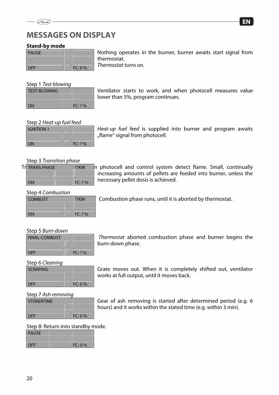
MESSAGES ON DISPLAY Stand-by mode
Nothing operates in the burner, burner awaits start signal from thermostat. Thermostat turns on.
Step 1 Test blowing
Ventilator starts to work, and when photocell measures value lower than 5%, program continues.
Step 2 Heat-up fuel feed
Heat-up fuel feed is supplied into burner and program awaits „flame“ signal from photocell.
Step 3 Transition phase
Transition phase begins, when photocell and control system detect flame. Small, continually increasing amounts of pellets are feeded into burner, unless the necessary pellet dosis is achieved.
Step 4 Combustion Combustion phase runs, until it is aborted by thermostat.
Step 5 Burn-down
Thermostat aborted combustion phase and burner begins the burn-down phase.
Step 6 Cleaning Grate moves out. When it is completely shifted out, ventilator works at full output, until it moves back.
Step 7 Ash removing Gear of ash removing is started after determined period (e.g. 6 hours) and it works within the stated time (e.g. within 3 min).
Step 8: Return into standby mode.
PAUSE
OFF FC: 0 %
TEST-BLOWING
ON FC: ? %
IGNITION 1
ON FC: ? %
TRANS.PHASE ??KW
ON FC: ? %
COMBUST ??KW
ON FC: ? %
FINAL-COMBUST
OFF FC: ? %
SCRAPING
OFF FC: 0 %
STOKERTIME
OFF FC: 0 %
PAUSE OFF FC: 0 %

21
EN
MENU MESSAGES
Burner in standby mode.
Hold ”S” button
Here you can change burner output. Level 1 = 8 – 12 kW, Level 2 = 14 – 30 kW.
Range and output Levels are adjustable in advanced menu. Press ”+” button.
Here you can set supplied amount of pellets. It is not necessary, if correct weight of pellets had been set in the Pellet trim in service menu.
Press ”+” button. To clean burner or to abort operation from other reasons, press the „M“ button and the burn-
down mode begins. To restart burner after ash removing, press „M“.
Press ”+” button.
This internal recording can be helpful by troubleshooting, when burner stops and alarm is activated. Last 10 different error codes are recorded. For more information about error codes, see „Trou-
bleshooting“. Press ”+” button.
To enter into advanced menu you need password (code). It is nec-essary to be familiar with program functions of burner.
PAUSE OFF FC: 0 %
EFFECT LEVEL ENTER EXIT
PELLET-TRIM ENTER EXIT
MAKE FINAL COMB. ENTER EXIT
LOG ENTER EXIT
MENU/ADVANCED ENTER EXIT
22
EN
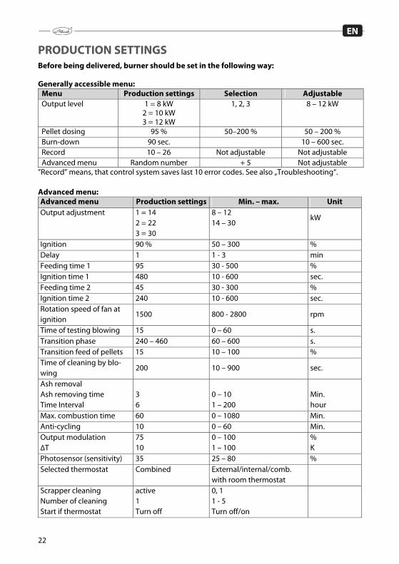
PRODUCTION SETTINGS Before being delivered, burner should be set in the following way: Generally accessible menu:
Menu Production settings Selection Adjustable Output level 1 = 8 kW
2 = 10 kW 3 = 12 kW
1, 2, 3 8 – 12 kW
Pellet dosing 95 % 50–200 % 50 – 200 % Burn-down 90 sec. 10 – 600 sec. Record 10 – 26 Not adjustable Not adjustable Advanced menu Random number + 5 Not adjustable
”Record” means, that control system saves last 10 error codes. See also „Troubleshooting“. Advanced menu:
Advanced menu Production settings Min. – max. Unit Output adjustment 1 = 14
2 = 22 3 = 30
8 – 12 14 – 30
kW
Ignition 90 % 50 – 300 % Delay 1 1 - 3 min Feeding time 1 95 30 - 500 % Ignition time 1 480 10 - 600 sec. Feeding time 2 45 30 - 300 % Ignition time 2 240 10 - 600 sec. Rotation speed of fan at ignition
1500 800 - 2800 rpm
Time of testing blowing 15 0 – 60 s. Transition phase 240 – 460 60 – 600 s. Transition feed of pellets 15 10 – 100 % Time of cleaning by blo-wing
200 10 – 900 sec.
Ash removal Ash removing time Time Interval
3 6
0 – 10 1 – 200
Min. hour
Max. combustion time 60 0 – 1080 Min. Anti-cycling 10 0 – 60 Min. Output modulation ∆T
75 10
0 – 100 1 – 100
% K
Photosensor (sensitivity) 35 25 – 80 % Selected thermostat Combined External/internal/comb.
with room thermostat
Scrapper cleaning Number of cleaning Start if thermostat
active 1 Turn off
0, 1 1 - 5 Turn off/on
23
EN
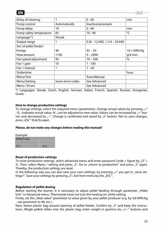
Delay of cleaning 1 0 - 60 min Pump control Automatically Inactive/automatic Pump delay 10 0 - 60 min Pump safety temperature 85 70 - 90 °C Language *) Slovak Output range 1 0 (8 – 12 kW), 1 (14 – 30 kW) Set. of pellet feeder: Energy Heat.amount
46 1100
45 – 50 0 – 2000
10 × kWh/kg g/6 min.
Fan speed adjustment 95 10 – 500 % Fan 1 gain 10 1 - 100 Fan 1 interval 1 1 - 50 Stokertime hour Menu/Test Auto/Manual Menu/Setting Saves error codes See Advanced Menu / Errors See Advanced
*) Languages: Slovak, Czech, English, German, Italian, French, Spanish, Russian, Hungarian, Greek. How to change production settings To change settings, select the required menu /parameters. Change actual values by pressing „+“ . O:...indicates actual value, N:...can be adjusted to new value. Values can be increased by „+“ but-ton and decreased by „–“. Change is confirmed and saved by „S“ button. Not to save changes, press „ESC“ (Exit/Escape). Please, do not make any changes before reading this manual! Example:
Reset of production settings To reset production settings, select advanced menu and enter password (code = figure by „O“ + 5). Then, select Menu / setting and press „S“. Go to „return to production“ and press „S“ again. Thereby, the production settings are reset. In the following way you can also save your own settings: by pressing „+“ you get to „Save set-tings?“. Save your settings by pressing „S“. Exit from menu by the „ESC“. Regulation of pellet dosing Before starting the burner, it is necessary to adjust pellet feeding through parameter „Pellet trim“ in Advanced menu. Thermostat must not turn the heating on, while setting. Firstly, set the „Heat value“ parameter to value given by your pellet producer (e.g. by 4,8 kWh/kg – set parameter to 48, etc.). Now, fasten plastic bag around opening of pellet feeder. Confirm by „S“ and keep the instruc-tions. Weigh pellets fallen into the plastic bag, enter weight in gramms by „+/–“ buttons and
EFFECT ADJ. O: 1 N: 2

24
EN
press „S“ to save value. This setting has to be done within 15 minutes. Otherwise, burner switch-es to standby mode. Weigh the pellets very precisely! After setting of the above mentioned parameters, all other parameters related with pellet supply are automatically adjusted by control system.
25
EN
HOW TO INSTALL PELLET FEEDER AND CONTAINER
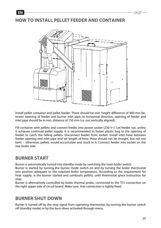
Install pellet container and pellet feeder. There should be min. height difference of 400 mm be-tween opening of feeder and burner inlet pipe. In horizontal direction, opening of feeder and inlet pipe should be in min. distance of 150 mm (i.e. not vertically aligned). Fill container with pellets and connect feeder into power socket (230 V~). Let feeder run, unless it achieves continual pellet supply. It is recommended to fasten plastic bag to the opening of feeder to catch the falling pellets. Disconnect feeder from socket. Install inlet hose between feeder opening and inlet pipe and set length of hose. Hose should not be straight, but not too bent – otherwise, pellets would accumulate and stuck in it. Connect feeder into socket on the rear boiler side.
BURNER START Burner is automatically turned into standby mode by switching the main boiler switch. Burner is started by turning the burner mode switch on and by turning the boiler thermostat into position adequate to the required boiler temperature. According to the requirement for heat supply, is the burner started and combusts pellets, until thermostat gives instruction for stop. Burner is alternatively controlled by boiler thermal probe, connected to the TS1 connection on the right upper side of circuit board. Make sure, that connection is tightly fixed.
BURNER SHUT DOWN Burner is turned off by the stop signal from operating thermostat, by turning the burner switch off (standby mode) or by the burn-down activated through menu.

26
EN
EMERGENCY SHUT DOWN
ATTENTION! In emergency case can be burner turned off by the main boiler switch and disconnection of boiler power plug from electrical socket.
CLEANING AND MAINTENANCE Burner has to be cleaned after every consumption of 2.000 kg pellets. It is based on assumption, that boiler keeps adequate amount of ash and the quality pellets are used. It is also recommended to sweep boiler exchanger parts at least 2x a month. 1. Clean pellet inlet into burner by bottle brush or other suitebla kit 2. Scrape ignition plate a grate and clean the holes in grate 3. Open the lid of turbulators and remove remaining dust (e.g. by vacuum cleaner). Make sure,
that dust is not hot and it cannot burn bag of vacuum cleaner. 4. Once in 3 months it is necessary to dismantle rotary chimney part and to remove accumu-
lated dust. ATTENTION! Keep ash in closed containers from inflammable material.
Maintenance once a year or in case of need (by a qualified person) Select Burn-down by menu buttons and wait, until the fuel in burner burns out. Turn burner off by burner switch and by main switch as well. Disconnect boiler plug from electrical socket. Open door with burner for approximately 90°. 1. Dismantle burner covering and clean photocell by cloth and soft abrasive detergent (tooth
paste). Be careful by flat cable and buttons of display! 2. Clean blades of ventilator – it is the best to blow them with compressed air. 3. Dismantle scraper and ignition plate. 4. Clean space behind ignition plate 5. Scrape ignition plate and scraper 6. Brush the grate properly and clean holes in grate 7. Assemble all the parts back 8. Clean container and pellet feeder from dust and small dirts 9. Check state of the pellet inlet hose. 10. Start pellet feeder by connecting the plug into electrical socket (230 V~) to fill it with pellets. 11. Adjust the amount of pellets to be supplied

27
EN
TROUBLESHOOTING Burner stopped. Check alarm indicated on display. If display is black and without text, check thermal protection of boiler. If there is no error, proba-bly it was switched off by thermal fuse. To restart burner, disconnect it from electricity, remove the cover and press the small button between connections of thermal fuse. Thermal fuse is placed directly on the fuel inlet pipe. After restarting, Mount the cover back and enable the en-ergy supply. Burner thermal fuse turns off by temperature of 93°C. Displayed message Explanation Recorded er-
ror code ERROR:IGNITION FAILED 10 ERROR: LOST FIRE Extinction by heating, restart failed 11 ERROR: PHOTOSENS Faulty photocell, abnormal light 12 ERROR: PCB OVERHEATED Too high temperature under cover 13 ERROR: TEMP SENSOR LOW Faulty thermal probe of built-in oper-
ating thermostat 14
ERROR: TEMP SENSOR OVERHEAT Faulty thermal probe of built-in oper-ating thermostat
15
ERROR: OPTOCOULPER Faulty PCB 16 ERROR: FAN ALWAYS ON Fan works, when not necessary 18 ERROR: FAN STOP Fan stopped, when not necessary 19 ERROR: FAN SPPED Fan rotates too slowly 20 ERROR: IGNITION 1 First ignition trial failed 21 ERROR: STOKER Pellet feeder is not connected to
burner 22
ERROR: FINAL COMBUST FAILED Photocell receives signal even 15 minutes after selecting „Burn down“
23
ERROR: BACKLIGHT Photocell detects no flame, ignition failed
24
ERROR: NO CLEANING Error in circuit board of scraper or in grate gear
25
ERROR: SLOW CLEANING Grate moves too slowly 26
28
EN
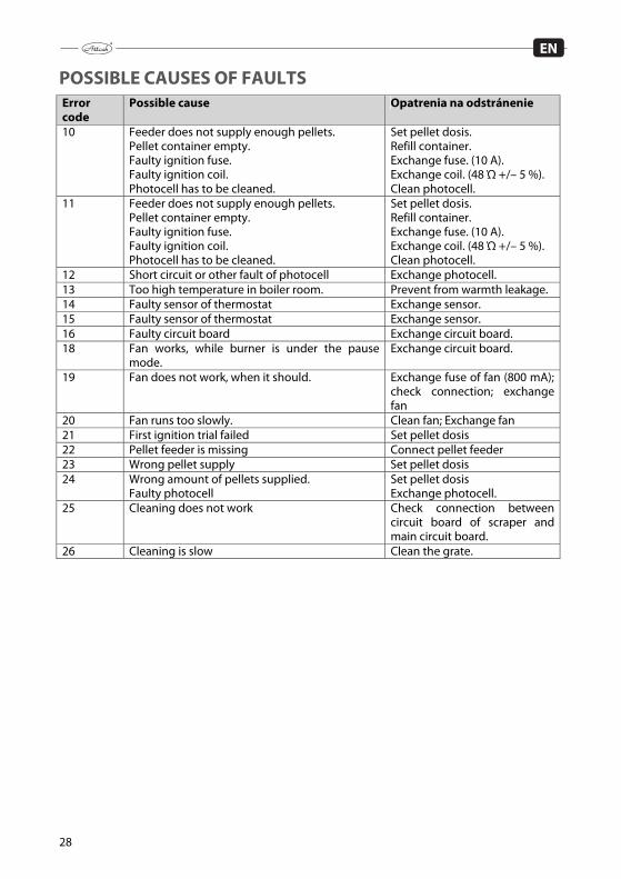
POSSIBLE CAUSES OF FAULTS Error code
Possible cause Opatrenia na odstránenie
10 Feeder does not supply enough pellets. Pellet container empty. Faulty ignition fuse. Faulty ignition coil. Photocell has to be cleaned.
Set pellet dosis. Refill container. Exchange fuse. (10 A). Exchange coil. (48 Ώ +/– 5 %). Clean photocell.
11 Feeder does not supply enough pellets. Pellet container empty. Faulty ignition fuse. Faulty ignition coil. Photocell has to be cleaned.
Set pellet dosis. Refill container. Exchange fuse. (10 A). Exchange coil. (48 Ώ +/– 5 %). Clean photocell.
12 Short circuit or other fault of photocell Exchange photocell. 13 Too high temperature in boiler room. Prevent from warmth leakage. 14 Faulty sensor of thermostat Exchange sensor. 15 Faulty sensor of thermostat Exchange sensor. 16 Faulty circuit board Exchange circuit board. 18 Fan works, while burner is under the pause
mode. Exchange circuit board.
19 Fan does not work, when it should. Exchange fuse of fan (800 mA); check connection; exchange fan
20 Fan runs too slowly. Clean fan; Exchange fan 21 First ignition trial failed Set pellet dosis 22 Pellet feeder is missing Connect pellet feeder 23 Wrong pellet supply Set pellet dosis 24 Wrong amount of pellets supplied.
Faulty photocell Set pellet dosis Exchange photocell.
25 Cleaning does not work Check connection between circuit board of scraper and main circuit board.
26 Cleaning is slow Clean the grate.
29
EN
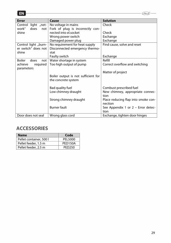
Error Cause Solution Control light „net-work“ does not shine
No voltage in mains Fork of plug is incorrectly con-nected into el.socket Wrong power switch Damaged power plug
Check Check Exchange Exchange
Control light „burn-er switch“ does not shine
No requirement for heat supply Disconnected emergency thermo-stat Faulty switch
Find cause, solve and reset Exchange
Boiler does not achieve required parameters
Water shortage in system Too high output of pump Boiler output is not sufficient for the concrete system Bad quality fuel Low chimney draught Strong chimney draught Burner fault
Refill Correct overflow and switching Matter of project Combust prescribed fuel New chimney, appropriate connec-tion Place reducing flap into smoke con-nection See Appendix 1 or 2 – Error detec-tion
Door does not seal Wrong glass cord Exchange, tighten door hinges
ACCESSORIES Name Code Pellet container, 500 l PEL5000 Pellet feeder, 1.5 m PED150A Pellet feeder, 2.5 m PED250

30
EN
ADVANCED MENU Following data/parameters are adjustable by qualified person only. All aspects of the advanced menu are available by pressing the „S“ button. Actual setting is per-manently indicated in the left bottom corner by „O:“ (time/value), while new value is given in the right buttom corner by „N:“ (time/value). To increase and decrease time or values, press buttons „+“ and „–“. To confirm and save new values, press „S“. To exit without saving, press „ESC“. To enter into advanced menu, add 5 to the displayed random number. Example: there can be „18“ by both – „O:“ and „N:“. Now, press „+“, unless „N:18“ changes to „N:23“ and press „S“. Thereby it is enabled to enter into the advanced menu. Example:
Old New Output setting:
Here you can select three outputs as FINAL OUTPUTS in generally accessible menu (8 – 30 kW).
When you press „S” by „EFFECT ADJ.” message, in the left upper corner appears „EFFECT 1 (kW)“ and in the left bottom corner appears „O:14“ (i.e. actual value of the final output in kW). Then, the second output level is displayed („EFFECT 2“) to be set to the required value. If you do not with to change it, press „S“ to save the displayed value (e.g. „N:22“ – EFFECT 2 – thereby, the second output level will be 22 kW). At the end is third output level displayed ("EFFECT 3") to be set for required value. If you do not want to change it press again "S" button to save displayed value (e.g. "N:30" - the third output will be set for 30 kW). To let display without saving changes, press „ESC“. Ignition setting:
Here you can adjust ignition fuel feed in %. This value had been automatically calculated adequately to the weight entered by the feeder setting – amount.
After pressing „S“, the „Ignition dosis 1“ is displayed in the left upper corner . Changes are made in %, first dosis had been pre-set to 170 g. If you increase this amount to 110 %, the first dosis will be changed to 187 g. If the first trial of burner ignition fails, the „Ignition dosis 2“ is activated. It is set by production to 45% from 170 g, i.e. 76,5 g.
MENU/ADVANCED O: 18 N: 23
EFFECT ADJ. ENTER > EXIT
IGNITION ENTER < > EXIT

31
EN
Setting of test-blow time Testblow time represents period of ventilation of boiler and chimney, before the combustion starts (10–100 seconds). By boilers with difficulty to achieve own draught it is suitable to
increase the testblow time. Production setting is 15 sec. Setting of transition phase:
Here you can set the period from the first flame detection until the full pellet dosis is supplied according to the final output.
There are two parameters of transition: the first is 14 kW and the second is 30 kW. Time set by the first parameter defines, how long it will take to achieve 14 kW (since the flame is detected) and time set by the second parameter defines, how long it will take to achieve 30 kW (since the flame is detected). Lower required output needs shorter time to be achieved. Setting of supply during transition phase:
Here you can set fuel supply during transition period since flame detection, until the 14 kW output is achieved. Set the required fuel dosis to be supplied into burner after flame
detection. Setting from production is 15% of full dosis for 14 kW. Setting of cleanblow time:
Cleanblow is activated, when thermostat turns off and the value detected by photocell decreases under 12 %.
Setting of ash removing:
Ash removing starts automatically in the intervals set from 1 to 200 hours for the pre-set operation period.
Setting of max. combustion time:
By this parameter you can set max. period of permanent burner operation.
Setting of min. pause between burn-down and ignition:
This parameter ensures, that the burner will not be started im-mediately after burner-out, but after the adjusted period.
Modulation:
By adjusted temperature difference ∆T, boiler output automati-cally decreases under the set level before the required boiler temperature is achieved.
Setting the photocell sensitivity:
Here you can set photocell sensitivity, i.e. value of light (in %) that will control system consider as a flame. It should not be necessary to adjust sensitivity for light, if the
photocell is installed correctly. Production setting is 50 %.
TESTBLOW TIME ENTER < > EXIT
TRANS.PHASE ENTER < > EXIT
TRANS.FEED ENTER < > EXIT
CLEANBLOW TIME ENTER < > EXIT
ASH AUGER ENTER < > EXIT
MAX. COMB. TIME ENTER < > EXIT
ANTI-CYCLING ENTER < > EXIT
MODULATION. ENTER < > EXIT
PHOTOSENSOR ENTER < > EXIT

32
EN
Selection of thermostat: Here you select the required thermostat: external boiler thermo-stat or burner thermal probe or combination with room thermo-stat.
If you use burner thermal probe, you can set 2 parameters. Select the start temperature as first and save the value by pressing „S“ button. Then you can change stop temperature and save it by „S“. Burner will operate in the range of the actually adjusted temperatures. Difference between start and stop temperature should be at least 5°C. Grate cleaning:
This parameter determines, if and when will be the grate clean-ing activated – before ignition or after burn-down.
Pump control:
This parameter determines, if the circuit pump will be controlled or not. If this function is activated you have to set PUMP DELAY.
Pump security:
After exceeding this temperature the pump always starts.
Selection of language:
You can select Slovak, Czech, English, German, Italian, French, Spanish, Russian Hungarian or Swedish language.
Setting of output range:
Burner can work with output range of 8– 14 kW, 14–22 kW or 22–30 kW, according to the range determined by this parameter.
Setting of pellet dosing:
= The most important parameter of control system! Here you can set pellet amount supplied by feeder by full operation. To set pellet amount you need bag and very precise scale. Firstly
you work with parameter Heat value (kWh/kg). After entering this value, text „Put the bag on“ is displayed (pellet feeder should be totally filled with pellets). Put the bag on and press „S“. Watch the countdown on display, while the feeder works for 6 minutes. Then, enter weight of the fallen pellets by pressing „+“ and „–“ a nd confirm / save it by „S“ button. Ventilator setting:
By this parameter you can adjust flue gas by using the flue ana-lyser for CO and CO2 content in flue gas.
THERMOSTAT ENTER < > EXIT
SCRAPPER ENTER < > EXIT
PUMP CONTROL ENTER < > EXIT
PUMP SAFETY TEMP ENTER < > EXIT
LANGUAGE ENTER < > EXIT
EFFECT SPAN ENTER < > EXIT
STOKER ADJ. ENTER < > EXIT
FANFACTOR ENTER < > EXIT
33
EN
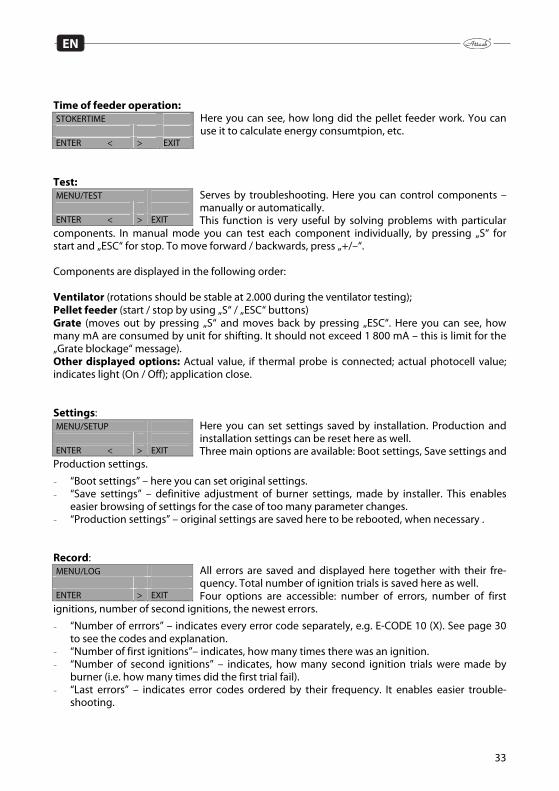
Time of feeder operation:
Here you can see, how long did the pellet feeder work. You can use it to calculate energy consumtpion, etc.
Test:
Serves by troubleshooting. Here you can control components – manually or automatically. This function is very useful by solving problems with particular
components. In manual mode you can test each component individually, by pressing „S“ for start and „ESC“ for stop. To move forward / backwards, press „+/–“. Components are displayed in the following order: Ventilator (rotations should be stable at 2.000 during the ventilator testing); Pellet feeder (start / stop by using „S“ / „ESC“ buttons) Grate (moves out by pressing „S“ and moves back by pressing „ESC“. Here you can see, how many mA are consumed by unit for shifting. It should not exceed 1 800 mA – this is limit for the „Grate blockage“ message). Other displayed options: Actual value, if thermal probe is connected; actual photocell value; indicates light (On / Off); application close. Settings:
Here you can set settings saved by installation. Production and installation settings can be reset here as well. Three main options are available: Boot settings, Save settings and
Production settings.
- “Boot settings” – here you can set original settings. - “Save settings” – definitive adjustment of burner settings, made by installer. This enables
easier browsing of settings for the case of too many parameter changes. - “Production settings” – original settings are saved here to be rebooted, when necessary . Record:
All errors are saved and displayed here together with their fre-quency. Total number of ignition trials is saved here as well. Four options are accessible: number of errors, number of first
ignitions, number of second ignitions, the newest errors.
- “Number of errrors” – indicates every error code separately, e.g. E-CODE 10 (X). See page 30 to see the codes and explanation.
- “Number of first ignitions”– indicates, how many times there was an ignition. - “Number of second ignitions” – indicates, how many second ignition trials were made by
burner (i.e. how many times did the first trial fail). - “Last errors” – indicates error codes ordered by their frequency. It enables easier trouble-
shooting.
STOKERTIME ENTER < > EXIT
MENU/TEST ENTER < > EXIT
MENU/SETUP ENTER < > EXIT
MENU/LOG ENTER > EXIT

34
EN
INSTRUCTIONS TO DISPOSAL OF PRODUCT AFTER EXPIRA-TION OF ITS LIFETIME Disposal of product (boiler) has to be ensured by a scrapyard, eventually by a disposal site con-trolled by appropriate municipal authority.
DISPOSAL OF PACKAGING Disposal of packaging has to be ensured by a scrapyard, eventually by a disposal site controlled by appropriate municipal authority.
ACCESSORIES The ATTACK PELLET 30 AUTOMATIC Plus boiler is delivered functionally tested. It is packed and placed on wooden pallet. Pellet feeder is packed separately. Delivery includes the following accessories: - Manual for attendance - Guarantee letter Recommended fuel feeder is the standard ATTACK feeder of 1,5 m length.
Information about processing of personal data Dear Customer, You provide us your personal information by completing and sending the Boiler start-up recor-dand our company becomes your personal data manager in relation to you. We hereby would like to inform you why and how we process your personal information, how we collect your personal information, for what purpose we handle it and the legal basis of such processing, how we handle personal data and what your rights are in relation to processing your personal data. Please read the following information carefully before providing us your personal details. In case of any questions related to the processing of your personal data, please do not hesitate to contact us at tel. no. 00421 43 400 3131 or [email protected]. Privacy Manager: ATTACK, s. r. o., with its registered office at Dielenská Kružná 5020, 038 61 Vrútky, Slovak Re-public Tel .: +421 43 4003 101 Fax .: +421 43 3241 129 E-mail: [email protected] Web: http://www.attack.sk Processing of personal data We will only process the personal information you provide to us in the Boiler start-up record, i.e.: - Name - Surname - Address - Phone - Type and serial number of the product Purpose and legal basis for the processing of your personal data We will process your personal data for the following purposes and on the basis of the following legal bases.
1) For the purposes of direct marketing, which is a legitimate interest of our company. The legal basis here is Art. Article 6 1. Letter. (f) Regulation (EU) 2016/679 of the European Par-liament and of the Council of 27 April 2016 on the protection of natural persons with re-gard to the processing of personal data and on the free movement of such data, and re-pealing Directive 95/46/EC (General Data Protection Regulation). The proccesing based on our legitimate interest, i.e. direct marketing, is following: Your personal data will be stored in our electronic database which is managed directly and only by us. This electronic database is stored and secured on the property of our company. Your personal data will be used by our legitimate interest only in order to be able to send you an offer of our new products, especially in the event of the end of the expected life of product which you enter your personal data in the Boiler start-up record in if our company develops a newer and more technologically superior and better pro-duct that could replace the product in which you enter your personal data into the in the Boiler start-up record. Direct marketingis our legitimate interest and the one of two purposes of processing of your personal data, i. e. direct offer of our products sent to you.
2) The legal basis for fulfilling the extended warranty agreement on the product in which you enter the Boiler Startup Record whereare your personal data is Art. Article 6 1. Letter.
2
(f) Regulation (EU) 2016/679 of the European Parliament and of the Council of 27 April 2016 on the protection of natural persons with regard to the processing of personal data and on the free movement of such data, and repealing Directive 95/46/EC (General Data Protection Regulation).
This processing that is required to meet the extended warranty agreement for a product you are one of the parties will be following: Our company provides you with an extended contractual warranty (beyond the statutory warranty) in such situation that you comply with the warranty conditions (see the warran-ty conditions in the Instruction for use, in whichthere is the Boiler start-up record with your personal data ). In order to provide you with this extended contractual warranty we need to know who is the other party and whether you are performing your obligations under this agreement especially the mandatory annual service inspections. Therefore we need you to send us a record of this inspection after each annual inspection (max. 5 in-spections) and we will declare in our database that you fulfill the terms of the contractual guarantee. Since each contract has at least two contracting parties we need your personal data to identify you as a party and identify a specific product for the purposes of fulfilling the ex-tended warranty agreement. We would not be able to fulfill our obligations under the ex-tended warranty agreementproperly without these data. Our legitimate interest and one of the two purposes of processing your personal data is therefore the fulfillment of the contract, that is, the fulfillment of the contract for exten-sion of the contractual guarantee.
Processing of personal data for both purposes is done manually and also in electronic informa-tion systems. However these systems are subject to rigorous and constant physical and technical control. All persons who, on the basis of our instructions and our credentials, come in contact with personal data in the framework of their work or contractual obligations are bound by confi-dentiality. Category of recipients of personal data We process your personal data primarily by ourselves. However it may happen that we will have to use the services of another entity to process personal data for any of the above mentioned purposes. In this case the relationship between us and the third party will be the relationship between the administrator andthe processor and we will make an agre-ement with this processor about the processing the personal data in order to guarantee the security and legality of processing your personal data. Your personal data may therefore be sold to the recipient of the following categories:
a) A company that distributes our products in the territory of a member state of the Europe-an Union in which you have purchased a product which you enter your personal data in the Boiler start-up record in or in which such a product is put into service on your request
b) A company providing bulk mailing services
The length of time the personal data will be stored We will process your personal data for at least the duration of the contractual warranty (i.e. for 5 years) for the purposes of fulfilling the warranty agreement and at most for thetime of assumed lifetime of the products for which the Boiler start-uprecord for the purposes of direct marketing. Raising objections toprocessing of personal data Whenever you have the right to object to our processing of your data for direct marketing pur-poses (see Purpose and legal basis for processing your personal data, item 1) above). If you have

3
an objection to our processing of your direct marketing data, by the date of your objection will cease our processing your personal data for direct marketing purposes. The objection to the processing of your personal data for direct marketing purposes can be sent to us by post to: ATTACK, s. r. o., Dielenská Kružná 5020, 038 61 Vrútky, Slovak Republic. In the objection, it is suf-ficient to provide the name, address and the text "I hereby raise an objection to the processing of my personal data for the purposes of direct marketing" and your signature. We always inform you about the accepting your requestwithout delay. Please note that the right to object can not be invoked against our processing of your personal data necessary for the purpose of fulfilling the extended warranty agreement. Your other rights related to the processing of personal data Please note that you also have the following rights in relation to our processing of your personal information:
• to ask for information about what personal data is processed by us, • to request access to these data and let them update or fix, • to require the deletion of these personal data, or the limitation of their processing, • to raise objection to the processing of your personal data, • the right to the portability of your personal data, • in case of doubt regarding compliance with the obligations related to the processing of
your personal data, contact the Administrator or the Office for Personal Data Protection.
You may enforce these rights to our company by the same procedure as the right to raise objec-tions to the processing of personal data.

The product meets technical standards and technical conditions. The product was made according to valid drawing documentation with the required quality and approved by the State testing institute.
Warranty Certificate
Guarantee
Type:
The company ATTACK, s.r.o. warrants for this product only if there have been met conditions of the warranty in time 24 months - 2 years - from the date of starting the boiler up.
The serial num. of the boiler:
Insert barcode here
Date of shipment from manufacturer:

The waranty conditions:The warranty covers all faults of the device and its components that have resulted from faulty material or mista-kes made by processing of the material.The warranty does not apply to gaskets, sealing cords, insulating materials, fireclay fillings, ignition spirals.
The warranty for the device is subject to the following conditions: a warranty card fully completed will be submitted to the complaint the installation of the equipment was carried out by a qualified employee of a professional installation company assembly and commissioning were confirmed in the warranty card the device will be used exactly according to the manufacturer's instructions and recommendations which are
listed in the installation manual if the system has been cleaned before installing and starting the system, the treated heating water and the mo-
unted filter
In the absence of any defect or fault caused by unprofessional operation by the customer, the costs associated with the work of the serviceman/technician are covered by the person who required for the repair.
The warranty claim expires and does not cover faults and damages that have arisen from: damage during transport breaking the rules about the installation, operating and maintenance instructions from the instructions of use violent mechanical damage unprofessional repairs or modifications, unprofessional operation and transportation if the warranty card is not completed properly a natural calamity arbitrary customer's conversion of device by making a design change or by modifying the text of the warranty certificate do not carry out a mandatory service visit within a given time install the device in a dirty and aggressive environment by clogging or clogging the boiler body with dirt from the system and water
The boiler is not subject of the warranty if: it is not operated with the prescribed fuel: for gasification boilers - wood with a humidity content not exceeding 20%, or with a fuel not specified by the ma-
nufacturer for pellet boilers - wood pellets of 6 mm diameter, max. length 35 mm, according to DIN 51 731-HP 5 or DIN Plus
or EN 14961-2-A1 Regumat ATTACK-OVENTROP will not be installed in the system to ensure that the boiler return temperature is
at least 65 ° C during operation there is no functional thermostatic valve installed to the boiler for cooling circuit connected to the cooling wa-
ter source it is not connected to the chimney with the prescribed dimensions specified in the operating instructions
Instructions for complaint:To make a warranty service, please contact the appropriate serviceman/technician with the following information: the exact address and contact of the user where the device is installed the approximate nature of the fault when and by whom device has been installed and put into operation device type, serial number and date of manufactureAfter completing there will be made a record of reparation and the user will confirm the work.The serviceman/technician is obligated to keep the user proof of repair. If the Service Officer detects any device in-terference or other damage and does not carry out the required service inspection, he is required to notify the user that the repair will be carried at his own expense and at the same time loses his / her entitlement to the next warranty.

ATTA
CK, s
.r.o.
– 0
7/20
18
ATTACK, s.r.o. • Dielenská Kružná 5020, 038 61 Vrútky • SlovakiaTel: +421 43 4003 101 • Fax: +421 43 3241 129 • E-mail: [email protected]
Export – tel: +421 43 4003 103 • Fax: +421 43 3241 129 • E-mail: [email protected]
ATTACK, s.r.o. producer reserves the right to change technical parameters and dimensions of boilers without previous warning.