Biofiltration-Nitrification Design Overview
62
Recirculating Aquaculture Systems Short Course Biofiltration Biofiltration ‐ ‐ Nitrification Nitrification Design Overview Design Overview James M. Ebeling, Ph.D. James M. Ebeling, Ph.D. Environmental Engineer Environmental Engineer Aquaculture Systems Technologies, LLC Aquaculture Systems Technologies, LLC New Orleans, LA New Orleans, LA Nitrogen is an essential nutrient for all living organisms and is found in proteins, nucleic acids, adenosine phosphates, pyridine nucleotides, and pigments. In the aquaculture environment, nitrogen is of primary concern as a component of the waste products generated by rearing fish. There are four primary sources of nitrogenous wastes: urea, uric acid, and amino acid excreted by the fish, organic debris from dead and dying organisms, uneaten feed, and feces, and nitrogen gas from the atmosphere. In particular, fish expel various nitrogenous waste products through gill diffusion, gill cation exchange, urine, and feces. The decomposition of these nitrogenous compounds is particularly important in intensive recirculating aquaculture systems (RAS) because of the toxicity of ammonia, nitrite, and to some extent, nitrate. The process of ammonia removal by a biological filter is called nitrification, and consists of the successive oxidation of ammonia to nitrite and finally to nitrate. The reverse process is called denitrification and is an anaerobic process where nitrate is converted to nitrogen gas. Although not normally employed in commercial aquaculture facilities today, the denitrification process (Chapter 9) is becoming increasingly important, especially in marine systems, as stocking densities increase and water exchange rates are reduced, resulting in excessive levels of nitrate in the culture system. Recently, zero-exchange management systems have been developed based on heterotrophic bacteria and promoted for the intensive production of marine shrimp and tilapia. In these systems, heterotrophic bacterial growth is stimulated through the addition of organic carbonaceous substrate. At high organic carbon to nitrogen (C/N) feed ratios, heterotrophic bacteria assimilate ammonia-nitrogen directly from the water replacing the need for an external fixed film biofilter.
-
Upload
razif-omar -
Category
Documents
-
view
103 -
download
1
description
bop
Transcript of Biofiltration-Nitrification Design Overview
Recirculating Aquaculture Systems Short Course
BiofiltrationBiofiltration‐‐NitrificationNitrificationDesign OverviewDesign Overview
James M. Ebeling, Ph.D.James M. Ebeling, Ph.D.
Environmental EngineerEnvironmental EngineerAquaculture Systems Technologies, LLCAquaculture Systems Technologies, LLC
New Orleans, LANew Orleans, LA
Nitrogen is an essential nutrient for all living organisms and is found in proteins, nucleic acids, adenosine phosphates, pyridine nucleotides, and pigments. In the aquaculture environment, nitrogen is of primary concern as a component of the waste products generated by rearing fish. There are four primary sources of nitrogenous wastes: urea, uric acid, and amino acid excreted by the fish, organic debris from dead and dying organisms, uneaten feed, and feces, and nitrogen gas from the atmosphere. In particular, fish expel various nitrogenous waste products through gill diffusion, gill cation exchange, urine, and feces. The decomposition of these nitrogenous compounds is particularly important in intensive recirculating aquaculture systems (RAS) because of the toxicity of ammonia, nitrite, and to some extent, nitrate. The process of ammonia removal by a biological filter is called nitrification, and consists of the successive oxidation of ammonia to nitrite and finally to nitrate. The reverse process is called denitrification and is an anaerobic process where nitrate is converted to nitrogen gas. Although not normally employed in commercial aquaculture facilities today, the denitrification process (Chapter 9) is becoming increasingly important, especially in marine systems, as stocking densities increase and water exchange rates are reduced, resulting in excessive levels of nitrate in the culture system. Recently, zero-exchange management systems have been developed based on heterotrophic bacteria and promoted for the intensive production of marine shrimp and tilapia. In these systems, heterotrophic bacterial growth is stimulated through the addition of organic carbonaceous substrate. At high organic carbon to nitrogen (C/N) feed ratios, heterotrophic bacteria assimilate ammonia-nitrogen directly from the water replacing the need for an external fixed film biofilter.
Recirculating Aquaculture Systems Short Course
Fish Culture Tank
AerationAir/Oxygen
Disinfection
BiofiltrationNitrification
SuspendedSolids
Sludge
SettableSolids
Sludge
Fine & DissolvedSolids Removal
Carbon DioxideRemoval
Sludge
95%5%
Monitoring &System Control
Overview of System DesignOverview of System Design
BiosecurityProgram
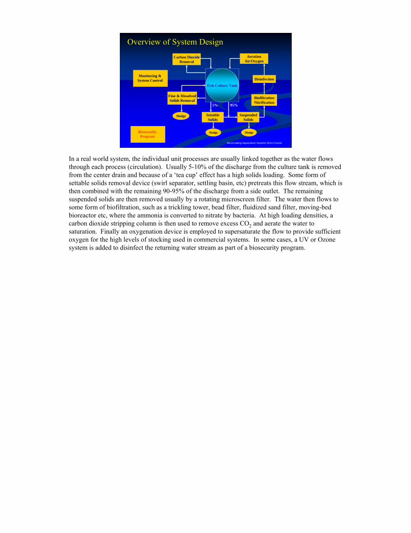
In a real world system, the individual unit processes are usually linked together as the water flows through each process (circulation). Usually 5-10% of the discharge from the culture tank is removed from the center drain and because of a ‘tea cup’ effect has a high solids loading. Some form of settable solids removal device (swirl separator, settling basin, etc) pretreats this flow stream, which is then combined with the remaining 90-95% of the discharge from a side outlet. The remaining suspended solids are then removed usually by a rotating microscreen filter. The water then flows to some form of biofiltration, such as a trickling tower, bead filter, fluidized sand filter, moving-bed bioreactor etc, where the ammonia is converted to nitrate by bacteria. At high loading densities, a carbon dioxide stripping column is then used to remove excess CO2 and aerate the water to saturation. Finally an oxygenation device is employed to supersaturate the flow to provide sufficient oxygen for the high levels of stocking used in commercial systems. In some cases, a UV or Ozone system is added to disinfect the returning water stream as part of a biosecurity program.
Recirculating Aquaculture Systems Short Course
BiofiltrationBiofiltrationNitrificationNitrification
NitrificationNitrification
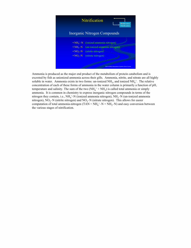
Inorganic Nitrogen Compounds
• NH4+-N (ionized ammonia nitrogen)
• NH3–N (un-ionized ammonia nitrogen)• NO2–N (nitrite nitrogen) • NO3–N (nitrate nitrogen)
Ammonia is produced as the major end product of the metabolism of protein catabolism and is excreted by fish as unionized ammonia across their gills. Ammonia, nitrite, and nitrate are all highly soluble in water. Ammonia exists in two forms: un-ionized NH3, and ionized NH4
+. The relative concentration of each of these forms of ammonia in the water column is primarily a function of pH, temperature and salinity. The sum of the two (NH4
+ + NH3) is called total ammonia or simply ammonia. It is common in chemistry to express inorganic nitrogen compounds in terms of the nitrogen they contain, i.e., NH4
+-N (ionized ammonia nitrogen), NH3–N (un-ionized ammonia nitrogen), NO2–N (nitrite nitrogen) and NO3–N (nitrate nitrogen). This allows for easier computation of total ammonia-nitrogen (TAN = NH4
+–N + NH3–N) and easy conversion between the various stages of nitrification.
Recirculating Aquaculture Systems Short Course
BiofiltrationBiofiltrationNitrificationNitrification
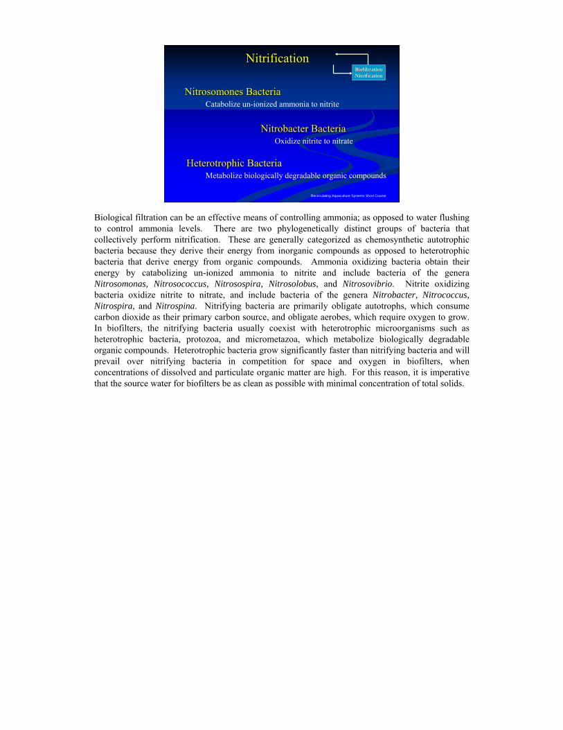
Nitrosomones BacteriaNitrosomones Bacteria
Nitrobacter BacteriaNitrobacter Bacteria
Catabolize un-ionized ammonia to nitrite
Oxidize nitrite to nitrate
NitrificationNitrification
Heterotrophic BacteriaHeterotrophic BacteriaMetabolize biologically degradable organic compounds
Biological filtration can be an effective means of controlling ammonia; as opposed to water flushing to control ammonia levels. There are two phylogenetically distinct groups of bacteria that collectively perform nitrification. These are generally categorized as chemosynthetic autotrophic bacteria because they derive their energy from inorganic compounds as opposed to heterotrophic bacteria that derive energy from organic compounds. Ammonia oxidizing bacteria obtain their energy by catabolizing un-ionized ammonia to nitrite and include bacteria of the genera Nitrosomonas, Nitrosococcus, Nitrosospira, Nitrosolobus, and Nitrosovibrio. Nitrite oxidizing bacteria oxidize nitrite to nitrate, and include bacteria of the genera Nitrobacter, Nitrococcus, Nitrospira, and Nitrospina. Nitrifying bacteria are primarily obligate autotrophs, which consume carbon dioxide as their primary carbon source, and obligate aerobes, which require oxygen to grow. In biofilters, the nitrifying bacteria usually coexist with heterotrophic microorganisms such as heterotrophic bacteria, protozoa, and micrometazoa, which metabolize biologically degradable organic compounds. Heterotrophic bacteria grow significantly faster than nitrifying bacteria and will prevail over nitrifying bacteria in competition for space and oxygen in biofilters, when concentrations of dissolved and particulate organic matter are high. For this reason, it is imperative that the source water for biofilters be as clean as possible with minimal concentration of total solids.
Recirculating Aquaculture Systems Short Course
BiofiltrationBiofiltrationNitrificationNitrification
Nitrosomones BacteriaNitrosomones Bacteria
Nitrobacter BacteriaNitrobacter Bacteria
2 NH4+ + OH - + 3 O2 ⇒ 2 H + + 2 NO2
- + 4 H2O
2 NO2 + 1 O2 ⇒ 2 NO3-
NitrificationNitrification
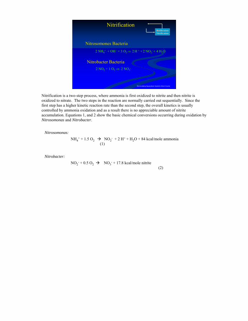
Nitrification is a two-step process, where ammonia is first oxidized to nitrite and then nitrite is oxidized to nitrate. The two steps in the reaction are normally carried out sequentially. Since the first step has a higher kinetic reaction rate than the second step, the overall kinetics is usually controlled by ammonia oxidation and as a result there is no appreciable amount of nitrite accumulation. Equations 1, and 2 show the basic chemical conversions occurring during oxidation by Nitrosomonas and Nitrobacter.
Nitrosomonas:NH4
+ + 1.5 O2 NO2- + 2 H+ + H2O + 84 kcal/mole ammonia
(1)
Nitrobacter:NO2
- + 0.5 O2 NO3- + 17.8 kcal/mole nitrite
(2)
Recirculating Aquaculture Systems Short Course
Nitrifying Bacteria Nitrifying Bacteria –– Overall ReactionOverall Reaction
BiofiltrationBiofiltrationNitrificationNitrification
NH4+ + 1.83 O2 + 1.97 HCO3
- →
0.0244 C5H7O2N + 0.976 NO3- + 2.90 H2O + 1.86 CO2
NitrificationNitrification
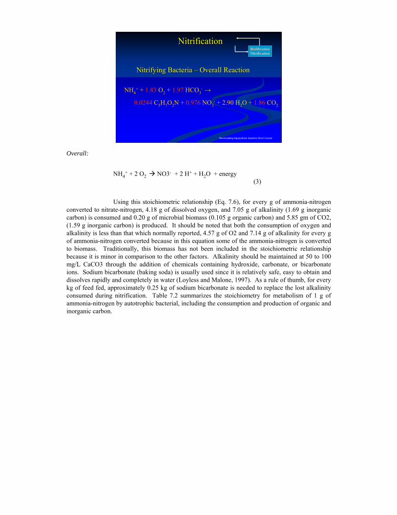
Overall:
NH4+ + 2 O2 NO3- + 2 H+ + H2O + energy
(3)
Using this stoichiometric relationship (Eq. 7.6), for every g of ammonia-nitrogen converted to nitrate-nitrogen, 4.18 g of dissolved oxygen, and 7.05 g of alkalinity (1.69 g inorganic carbon) is consumed and 0.20 g of microbial biomass (0.105 g organic carbon) and 5.85 gm of CO2, (1.59 g inorganic carbon) is produced. It should be noted that both the consumption of oxygen and alkalinity is less than that which normally reported, 4.57 g of O2 and 7.14 g of alkalinity for every g of ammonia-nitrogen converted because in this equation some of the ammonia-nitrogen is converted to biomass. Traditionally, this biomass has not been included in the stoichiometric relationship because it is minor in comparison to the other factors. Alkalinity should be maintained at 50 to 100 mg/L CaCO3 through the addition of chemicals containing hydroxide, carbonate, or bicarbonate ions. Sodium bicarbonate (baking soda) is usually used since it is relatively safe, easy to obtain and dissolves rapidly and completely in water (Loyless and Malone, 1997). As a rule of thumb, for every kg of feed fed, approximately 0.25 kg of sodium bicarbonate is needed to replace the lost alkalinity consumed during nitrification. Table 7.2 summarizes the stoichiometry for metabolism of 1 g of ammonia-nitrogen by autotrophic bacterial, including the consumption and production of organic and inorganic carbon.
Recirculating Aquaculture Systems Short Course
Nitrification (1 kg of feed @ 35% protein)
-----80.1-----2955.85 g CO2/ g NCO2
49.2----------0.9760.976 g NO3--N /g NNO3
--N
1.25-----5.3510.10.20 g VSSA / g NVSSA
(g)(g)(g)(g)StoichiometryProducts
NC inorganicC organicYields
---------------2114.18 g O2/ g NOxygen
-----85.6-----3557.05 g Alk/ g NAlkalinity
50.4----------50.4NH4+-N
(g)(g)(g)(g)StoichiometryConsumablesNC inorganicC organicConsumes
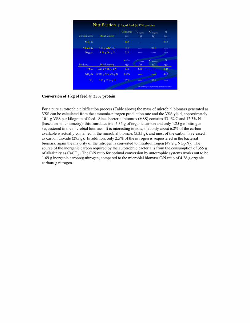
Conversion of 1 kg of feed @ 35% protein
For a pure autotrophic nitrification process (Table above) the mass of microbial biomass generated as VSS can be calculated from the ammonia-nitrogen production rate and the VSS yield, approximately 10.1 g VSS per kilogram of feed. Since bacterial biomass (VSS) contains 53.1% C and 12.3% N (based on stoichiometry), this translates into 5.35 g of organic carbon and only 1.25 g of nitrogen sequestered in the microbial biomass. It is interesting to note, that only about 6.2% of the carbon available is actually contained in the microbial biomass (5.35 g), and most of the carbon is released as carbon dioxide (295 g). In addition, only 2.5% of the nitrogen is sequestered in the bacterial biomass, again the majority of the nitrogen is converted to nitrate-nitrogen (49.2 g NO3-N). The source of the inorganic carbon required by the autotrophic bacteria is from the consumption of 355 g of alkalinity as CaCO3. The C/N ratio for optimal conversion by autotrophic systems works out to be 1.69 g inorganic carbon/g nitrogen, compared to the microbial biomass C/N ratio of 4.28 g organic carbon/ g nitrogen.
Recirculating Aquaculture Systems Short Course
StartStart--up Curve for a Biological Filterup Curve for a Biological FilterBiofiltrationBiofiltrationNitrificationNitrification
NitrificationNitrification
0
5
1 0
1 5
0 7 1 4 2 1 2 8 3 5 4 2
T im e (d a ys )C
once
ntra
tion
(ppm
)
T A N
N O 2
N O 3
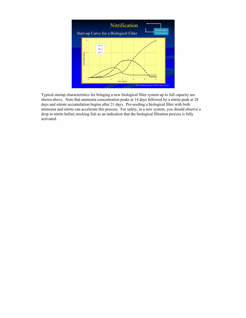
Typical startup characteristics for bringing a new biological filter system up to full capacity are shown above. Note that ammonia concentration peaks at 14 days followed by a nitrite peak at 28 days and nitrate accumulation begins after 21 days. Pre-seeding a biological filter with both ammonia and nitrite can accelerate this process. For safety, in a new system, you should observe a drop in nitrite before stocking fish as an indication that the biological filtration process is fully activated.
Recirculating Aquaculture Systems Short Course
Ammonia ProductionAmmonia ProductionBiofiltrationBiofiltrationNitrificationNitrification
5.93 g carbon dioxide1 g of ammonia yields:
1 g of ammonia consumes:
4.42 g nitrate NO3-
4.57 g oxygen7.14 g alkalinity
1 kg feed ⇒ about 0.03 kg ammonia – nitrogen
0.17 g cell mass
NitrificationNitrification
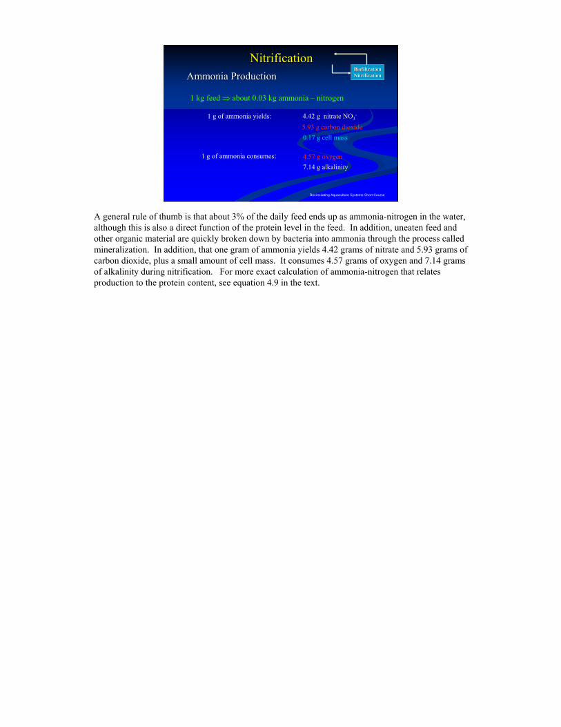
A general rule of thumb is that about 3% of the daily feed ends up as ammonia-nitrogen in the water, although this is also a direct function of the protein level in the feed. In addition, uneaten feed and other organic material are quickly broken down by bacteria into ammonia through the process called mineralization. In addition, that one gram of ammonia yields 4.42 grams of nitrate and 5.93 grams of carbon dioxide, plus a small amount of cell mass. It consumes 4.57 grams of oxygen and 7.14 grams of alkalinity during nitrification. For more exact calculation of ammonia-nitrogen that relates production to the protein content, see equation 4.9 in the text.
Recirculating Aquaculture Systems Short Course
Equilibrium Reaction Equilibrium Reaction -- AmmoniaAmmoniaBiofiltrationBiofiltrationNitrificationNitrification
(ionized) (unionized) TOXICTOXIC
NH4+ + OH - ⇔ NH3 + H2O
Note: NH4+-N + NH3-N ⇒ TAN
NH4--N ⇒ Ammonia - nitrogen
Increase in pH
Increase in temperature
Nitrification
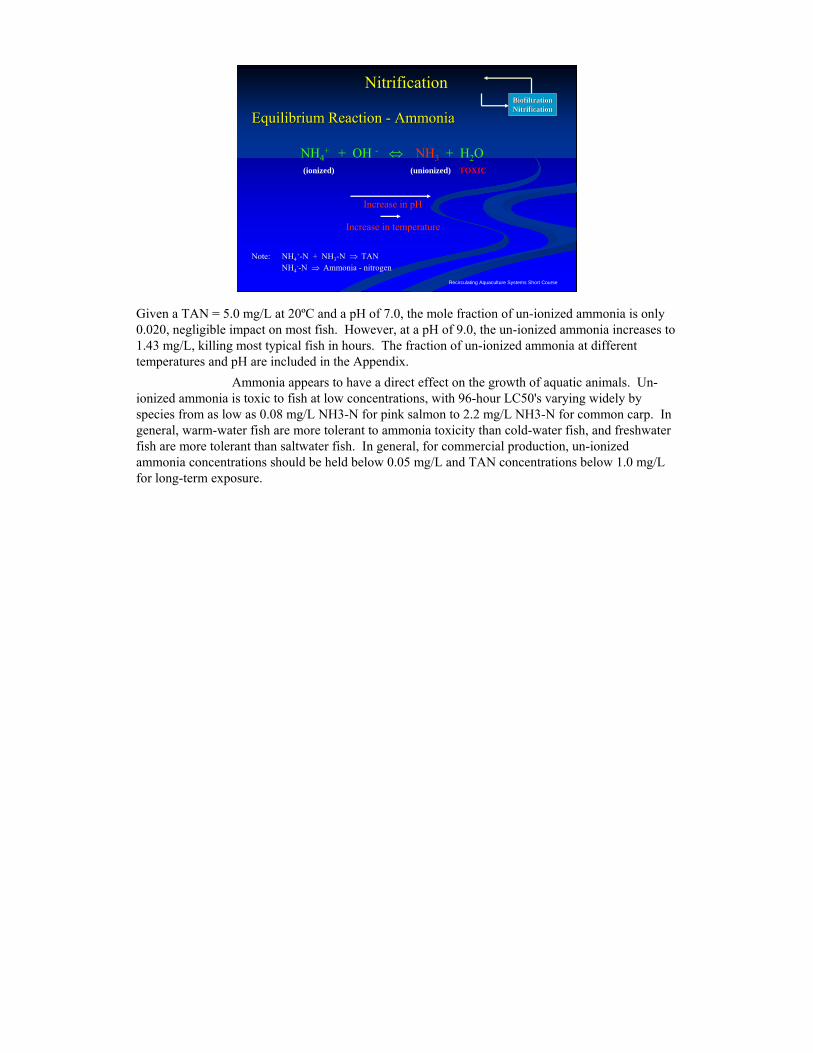
Given a TAN = 5.0 mg/L at 20ºC and a pH of 7.0, the mole fraction of un-ionized ammonia is only 0.020, negligible impact on most fish. However, at a pH of 9.0, the un-ionized ammonia increases to 1.43 mg/L, killing most typical fish in hours. The fraction of un-ionized ammonia at different temperatures and pH are included in the Appendix.
Ammonia appears to have a direct effect on the growth of aquatic animals. Un-ionized ammonia is toxic to fish at low concentrations, with 96-hour LC50's varying widely by species from as low as 0.08 mg/L NH3-N for pink salmon to 2.2 mg/L NH3-N for common carp. In general, warm-water fish are more tolerant to ammonia toxicity than cold-water fish, and freshwater fish are more tolerant than saltwater fish. In general, for commercial production, un-ionized ammonia concentrations should be held below 0.05 mg/L and TAN concentrations below 1.0 mg/L for long-term exposure.
Recirculating Aquaculture Systems Short Course
Percent unionized ammoniaPercent unionized ammonia--nitrogennitrogen
BiofiltrationBiofiltrationNitrificationNitrification
pHTemp. 6.0 6.5 7.0 7.5 8.0 9.0
10 - 0.1 0.2 0.6 1.8 15.715 - 0.1 0.3 0.9 2.7 21.520 - 0.1 0.4 1.2 3.8 28.425 0.1 0.2 0.6 1.8 5.4 36.330 0.1 0.3 0.8 2.5 7.5 44.6
Nitrification
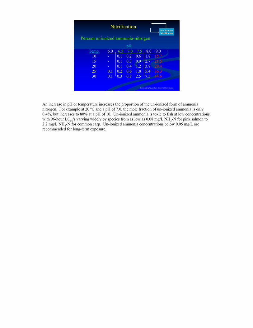
An increase in pH or temperature increases the proportion of the un-ionized form of ammonia nitrogen. For example at 20 ºC and a pH of 7.0, the mole fraction of un-ionized ammonia is only 0.4%, but increases to 80% at a pH of 10. Un-ionized ammonia is toxic to fish at low concentrations, with 96-hour LC50's varying widely by species from as low as 0.08 mg/L NH3-N for pink salmon to 2.2 mg/L NH3-N for common carp. Un-ionized ammonia concentrations below 0.05 mg/L are recommended for long-term exposure.
Recirculating Aquaculture Systems Short Course
Equilibrium Reaction Equilibrium Reaction –– NitriteNitrite
BiofiltrationBiofiltrationNitrificationNitrification
NO2- + H2O ⇔ HNO2 + OH -
Note: NO2--N ⇒ Nitrite - nitrogen
mitigated by adding salt (chlorides)
Decrease in pH
NitrificationNitrification
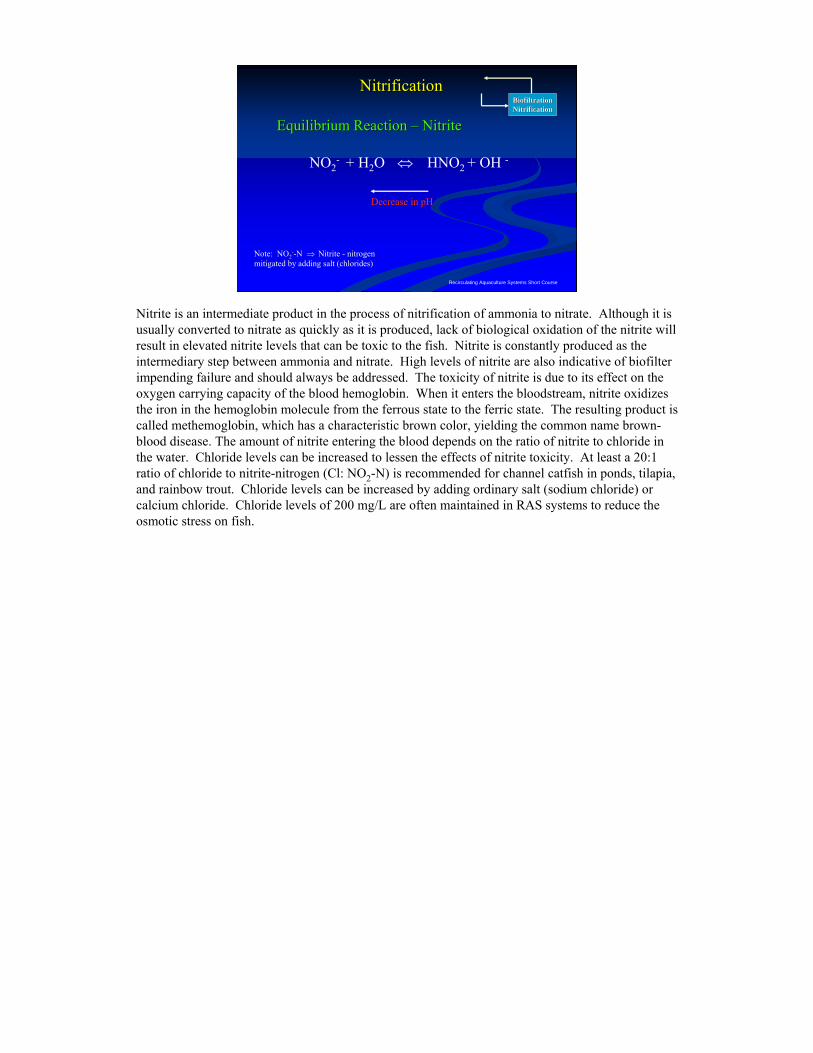
Nitrite is an intermediate product in the process of nitrification of ammonia to nitrate. Although it is usually converted to nitrate as quickly as it is produced, lack of biological oxidation of the nitrite will result in elevated nitrite levels that can be toxic to the fish. Nitrite is constantly produced as the intermediary step between ammonia and nitrate. High levels of nitrite are also indicative of biofilter impending failure and should always be addressed. The toxicity of nitrite is due to its effect on the oxygen carrying capacity of the blood hemoglobin. When it enters the bloodstream, nitrite oxidizes the iron in the hemoglobin molecule from the ferrous state to the ferric state. The resulting product is called methemoglobin, which has a characteristic brown color, yielding the common name brown-blood disease. The amount of nitrite entering the blood depends on the ratio of nitrite to chloride in the water. Chloride levels can be increased to lessen the effects of nitrite toxicity. At least a 20:1 ratio of chloride to nitrite-nitrogen (Cl: NO2-N) is recommended for channel catfish in ponds, tilapia, and rainbow trout. Chloride levels can be increased by adding ordinary salt (sodium chloride) or calcium chloride. Chloride levels of 200 mg/L are often maintained in RAS systems to reduce the osmotic stress on fish.
Recirculating Aquaculture Systems Short Course
BiofiltrationBiofiltrationNitrificationNitrification
NitrificationNitrification
High levels of nitrite can be produced under High levels of nitrite can be produced under conditions when there is an imbalance between conditions when there is an imbalance between populations of populations of NitrosomonasNitrosomonas and and NitrobacterNitrobacter, which , which can occur:can occur:•• within the first 4within the first 4--8 weeks of biofilter startup8 weeks of biofilter startup•• if inadequate surface area or dissolved oxygenif inadequate surface area or dissolved oxygen•• if ozone is used for an extended period and then if ozone is used for an extended period and then
turnedturned--off (Ooff (O33 + NO+ NO22-- NONO33-- + O+ O22))
High levels of nitrite can be produced under conditions when there is an imbalance between populations of Nitrosomonas and Nitrobacter, which can occur:
within the first 4-8 weeks of biofilter startupif inadequate surface area or dissolved oxygenif ozone is used for an extended period and then turned-off (O3 + NO2- ▬► NO3- + O2)
Recirculating Aquaculture Systems Short Course
Equilibrium Reaction Equilibrium Reaction –– NitrateNitrate
BiofiltrationBiofiltrationNitrificationNitrification
NO3-N
Note: NO3--N ⇒ Nitrate - nitrogen
Non-toxic (freshwater systems)
NitrificationNitrification
Nitrate is the end product of nitrification and is the least toxic of the nitrogen compounds, with a 96-h LC values usually exceeding 1000 mg NO3—N /L. In recirculation systems, nitrate levels are usually controlled by daily water exchanges. In systems with low water exchange or high hydraulic retention times, denitrification has become increasingly important.
Recirculating Aquaculture Systems Short Course
FACTORS AFFECTING NITRIFICATIONFACTORS AFFECTING NITRIFICATION
BiofiltrationBiofiltrationNitrificationNitrification
• pHpH•• AlkalinityAlkalinity•• TemperatureTemperature•• OxygenOxygen•• SalinitySalinity•• LightLight
Nitrification
The following sections will discuss in the major factors affecting the rate of nitrification, which include: pH, alkalinity, temperature, oxygen, ammonia, and salinity.
Recirculating Aquaculture Systems Short Course
•• pHpH
BiofiltrationBiofiltrationNitrificationNitrification
Optimum range Optimum range 6 6 -- 99(7.2(7.2--7.8)7.8)
Nitrification
The effect of pH on the nitrification rate for biofilters has been researched for more than sixty years, yet there is a wide range in reported pH optima (Biesterfeld et al., 2001). This suggests that the history and condition under which the bacteria are cultured may affect their response to pH (Kaiser & Wheaton, 1983). The most recent results suggest that the optimum range of pH for nitrification can range from 7.0 to 9.0 (Haug and McCarty, 1972; Chen, et al., 2006). The optimum pH for Nitrosomonas ranges from 7.2 to 7.8 (Loveless & Painter, 1968, Antoniou et al. 1990) and from 7.2 to 8.2 for Nitrobacter. Nitrifying biofilters have been operated over a much broader range from 6 to 9, due to the adaptation of the bacteria in a filter to actual operating conditions. It is probably a good idea to maintain pH near the lower end of the optimum pH for the nitrifying bacteria to minimize ammonia stress on the cultivated fish species. In addition, rapid changes in pH of more than 0.5 to 1.0 units over a short time span will stress the filter and require time for adaptation to the new environmental conditions.
Recirculating Aquaculture Systems Short Course
•• Alkalinity Alkalinity (50 (50 --150 mg/l as Ca CO150 mg/l as Ca CO33))
BiofiltrationBiofiltrationNitrificationNitrification
Formula Common Name Equivalent Weight
NaOH sodium hydroxide 40
Na2CO3 sodium carbonate 53
NaHCO3 sodium bicarbonate 83
CaCO3 Calcium Carbonate 50
CaO slaked lime 28
Ca(OH) 2 hydrated lime 37
Nitrification
0.0
2.0
4.0
6.0
8.0
10.0
55 60 65 70 75Day
Am
mon
ia-n
itrog
en (m
g/L
) .
0
50
100
150
200
250
300
350
Alk
alin
ity (m
g/L)
.
Tank 'B' - TAN
Tank 'B' - Alkalinity
Rule of Thumb:
0.25 lbs of baking soda per pound of feed
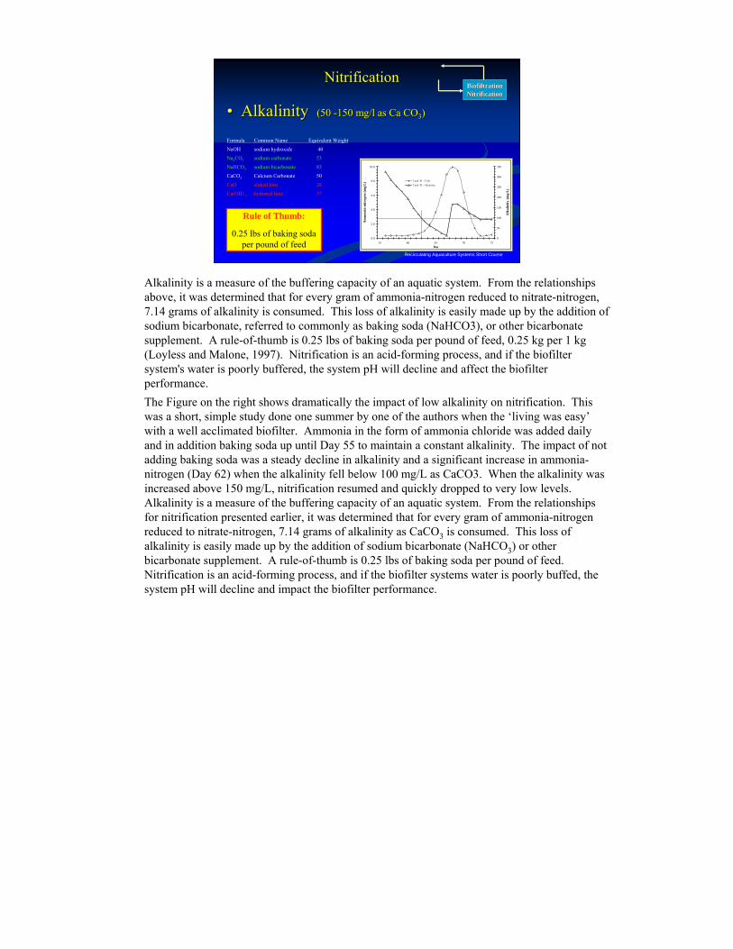
Alkalinity is a measure of the buffering capacity of an aquatic system. From the relationships above, it was determined that for every gram of ammonia-nitrogen reduced to nitrate-nitrogen, 7.14 grams of alkalinity is consumed. This loss of alkalinity is easily made up by the addition of sodium bicarbonate, referred to commonly as baking soda (NaHCO3), or other bicarbonate supplement. A rule-of-thumb is 0.25 lbs of baking soda per pound of feed, 0.25 kg per 1 kg (Loyless and Malone, 1997). Nitrification is an acid-forming process, and if the biofilter system's water is poorly buffered, the system pH will decline and affect the biofilter performance.The Figure on the right shows dramatically the impact of low alkalinity on nitrification. This was a short, simple study done one summer by one of the authors when the ‘living was easy’with a well acclimated biofilter. Ammonia in the form of ammonia chloride was added daily and in addition baking soda up until Day 55 to maintain a constant alkalinity. The impact of not adding baking soda was a steady decline in alkalinity and a significant increase in ammonia-nitrogen (Day 62) when the alkalinity fell below 100 mg/L as CaCO3. When the alkalinity was increased above 150 mg/L, nitrification resumed and quickly dropped to very low levels. Alkalinity is a measure of the buffering capacity of an aquatic system. From the relationships for nitrification presented earlier, it was determined that for every gram of ammonia-nitrogen reduced to nitrate-nitrogen, 7.14 grams of alkalinity as CaCO3 is consumed. This loss of alkalinity is easily made up by the addition of sodium bicarbonate (NaHCO3) or other bicarbonate supplement. A rule-of-thumb is 0.25 lbs of baking soda per pound of feed. Nitrification is an acid-forming process, and if the biofilter systems water is poorly buffed, the system pH will decline and impact the biofilter performance.
Recirculating Aquaculture Systems Short Course
•• TemperatureTemperature
BiofiltrationBiofiltrationNitrificationNitrification
Determined by the species cultured not biofilter needs
“Nitrification rates at 17 Deg. C would be 77% of the ratesobtained at 27 Deg. C, or a 27% reduction in rate”
Nitrification
Temperature plays a significant role in the nitrification reaction rate in suspended growth systems as it does in all chemical and biological kinetic reactions, although limited research is available to quantify the effects of temperature on fixed film nitrification rates (Okey and Albertson, 1989). Zhu and Chen (2002) studied the impact of temperature on nitrification rates in laboratory experiments, mathematical modeling, and sensitivity analysis. Their studies showed that the impact of temperature on the nitrification rate for fixed film nitrification was less than predicated by the van Hoff-Arrhenius equation. More specifically, Zhu and Chen showed that in the case of oxygen limitation, temperatures from 14 to 27 ºC had no significant impact on nitrification rate a fixed film bioreactor. Malone and Pfeiffer (2006) reported that although originally assumed to be an important factor in biofilter design, temperature is increasingly being viewed as a minor factor in controlling biofilter carrying capacities.
Recirculating Aquaculture Systems Short Course
•• OxygenOxygen
BiofiltrationBiofiltrationNitrificationNitrification
4.57 g O2 for each gram of TAN -> NO3
Rule of Thumb:Effluent from biofilter at least
2 mg/L Dissolved Oxygen (DO)
Nitrification
Oxygen can become the rate-limiting factor in certain biofilters, because of the low levels in the influent and the competing demands of the heterotrophic bacteria. For every gram of ammonia-nitrogen oxidized to nitrate-nitrogen, 4.57 g of oxygen is required. Knowles et al. (1965) studied nitrification with a mixed culture reactor and reported that DO affected the growth rate of Nitrosomonas very little at DO levels above 2.0 mg/L, but Nitrobacter exhibited a reduced growth rate at DO levels of less than 4 mg/L. Wheaton (1985) and Malone et al. (1998) state that biofilter effluent levels of at least 2 mg/L of oxygen are probably adequate to maintain maximum nitrification rates.
Recirculating Aquaculture Systems Short Course
•• SalinitySalinity
BiofiltrationBiofiltrationNitrificationNitrification
Bacteria can acclimate to almost any salinity range.
Nitrification
There is very limited information on the impact of salinity on nitrification. Salinity is similar to both temperature and pH, in that nitrifying bacteria can acclimate to almost any salinity range, given sufficient time. Chen, et al. (2006) reported that many engineering companies and pilot scale long term experiments with fresh and marine water recirculation systems suggest that the average removal rate is reduced by approximately 37% in salt water compared to fresh water. Rusten, et al. (2006) reported that data from commercial fish farms operating at a salinity of 21-24 ppt, indicated that the nitrification rate was approximately 60% of what would be expected in a freshwater system for Moving Bed BioReactors. Numerous researchers, including the authors, have observed that it takes significantly longer to fully acclimate a biofilter in salt water then in fresh water. Abrupt changes in salinity of greater than 5 g/L, will shock nitrifying bacteria and decrease the reaction rate for both ammonia-nitrogen and nitrite-nitrogen removal (Hochheimer, 1990).
Recirculating Aquaculture Systems Short Course
•• LightLight
BiofiltrationBiofiltrationNitrificationNitrification
Nitrification
Light has been shown to inhibit the growth of nitrifying bacteria.
Light has been shown to inhibit growth of the bacteria and can encourage the growth of algae on the biomedia.
Recirculating Aquaculture Systems Short Course
•• Ammonia ConcentrationAmmonia ConcentrationBiofiltrationBiofiltrationNitrificationNitrification
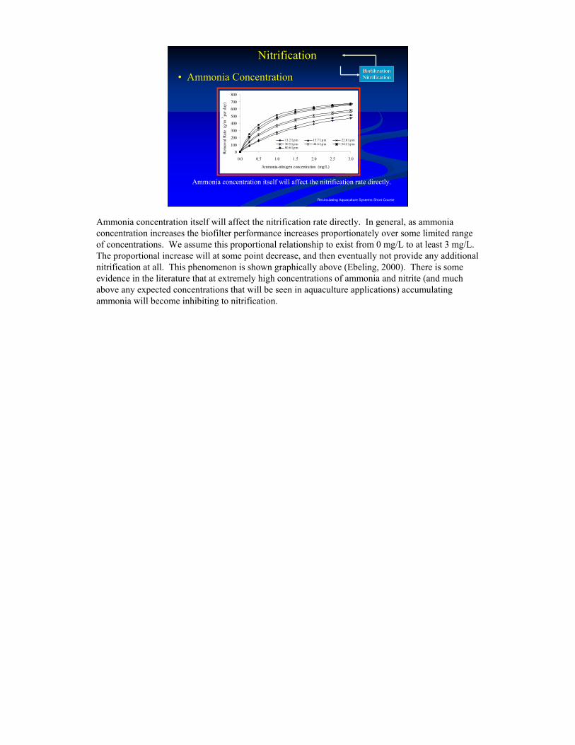
Ammonia concentration itself will affect the nitrification rate directly.
Nitrification
0
100
200
300
400
500
600
700
800
0.0 0.5 1.0 1.5 2.0 2.5 3.0
Ammonia-nitrogen concentration (mg/L)
Rem
oval
Rat
e (g
/m3
per d
ay)
13.2 Lpm 15.7 Lpm 22.0 Lpm30.5 Lpm 44.6 Lpm 54.2 Lpm80.6 Lpm
Ammonia concentration itself will affect the nitrification rate directly. In general, as ammonia concentration increases the biofilter performance increases proportionately over some limited range of concentrations. We assume this proportional relationship to exist from 0 mg/L to at least 3 mg/L. The proportional increase will at some point decrease, and then eventually not provide any additional nitrification at all. This phenomenon is shown graphically above (Ebeling, 2000). There is some evidence in the literature that at extremely high concentrations of ammonia and nitrite (and much above any expected concentrations that will be seen in aquaculture applications) accumulating ammonia will become inhibiting to nitrification.
Recirculating Aquaculture Systems Short Course
Terms Used To Describe BiofiltersTerms Used To Describe Biofilters
BiofiltrationBiofiltrationNitrificationNitrification
• Void Space / porosityVoid Space / porosity•• CrossCross--sectional Areasectional Area•• Hydraulic Loading RateHydraulic Loading Rate•• Specific Surface AreaSpecific Surface Area
Biofilters
It is helpful in any discussion of biofilter principals and advantages and disadvantages of the various choices to have a basic set of definitions and terminology. Generally, the following terms are used in the design and characterization of biofilters:
Recirculating Aquaculture Systems Short Course
Void Space / porosityVoid Space / porosity
BiofiltrationBiofiltrationNitrificationNitrification
Ratio of the volume of void spaces between media Ratio of the volume of void spaces between media particles and filter media volumeparticles and filter media volume
Biofilters
Terms Used To Describe BiofiltersTerms Used To Describe Biofilters
High void ratios reduce clogging
Void space is the volume not occupied by biofilter media, and void ratio is that volume divided by the total volume of the biofilter. High void ratios reduce clogging by having large open spaces that allow solids to pass easily through the filter.
Recirculating Aquaculture Systems Short Course
CrossCross--sectional Areasectional Area
BiofiltrationBiofiltrationNitrificationNitrification
Area of the filter bed material lookingArea of the filter bed material lookingin the direction of the water flowin the direction of the water flow..
Biofilters
Terms Used To Describe BiofiltersTerms Used To Describe Biofilters
Cross-sectional area refers to the area of the filter bed looking in the direction of the water flow. Filter top area is usually one of the last parameters selected in the filter design, to yield a desired hydraulic loading rate.
Recirculating Aquaculture Systems Short Course
Hydraulic Loading RateHydraulic Loading Rate
BiofiltrationBiofiltrationNitrificationNitrification
Volume of water flowing through the filter per unit of cross-sectional area of the filter bed per unit of time
(m3/m2/day) (gal/ft2/min)
Biofilters
Terms Used To Describe BiofiltersTerms Used To Describe Biofilters
Hydraulic loading rate is the volume of water pumped through the biofilter per unit of cross-sectional area of the filter per unit of time. Typically expressed as gpm/ft2 or m3/m2 day. There is usually both a minimum and a maximum hydraulic loading rate for biofilters.
Recirculating Aquaculture Systems Short Course
Specific Surface AreaSpecific Surface Area
BiofiltrationBiofiltrationNitrificationNitrification
Surface area of the media per unit volumeSurface area of the media per unit volume
(m(m22/m/m33)) (ft(ft22/ft/ft3 3 ))
Biofilters
Terms Used To Describe BiofiltersTerms Used To Describe Biofilters
Specific surface area is the surface area of the media per unit volume. The higher the specific surface area of a media, the more bacteria can grow on a unit volume, and the greater the total ammonia removal per unit volume of filter. The media size, void ratio and specific surface area are all interrelated. The smaller the size, the larger the specific surface ratio and the smaller the void ratio.
Recirculating Aquaculture Systems Short Course
Volumetric TAN conversion rateVolumetric TAN conversion rate
BiofiltrationBiofiltrationNitrificationNitrification
Terms Used To Describe Biofilter PerformanceTerms Used To Describe Biofilter Performance
Ammonia-nitrogen removal rate per unit volume of filter
[kg TAN /m3 day]
Biofilter PerformanceBiofilter Performance
Typical terms used to describe biofilter performance are based on either the volume of the media or its surface area. Although nitrification reaction rates are a surface area phenomenon, for fluidized sand beds and other granular media, sometimes the rate is easier expressed per unit volume rather than per unit surface area, due to the difficulty in measuring the actual media surface area.
Recirculating Aquaculture Systems Short Course
Areal TAN conversion rateAreal TAN conversion rate
BiofiltrationBiofiltrationNitrificationNitrification
Terms Used To Describe Biofilter PerformanceTerms Used To Describe Biofilter Performance
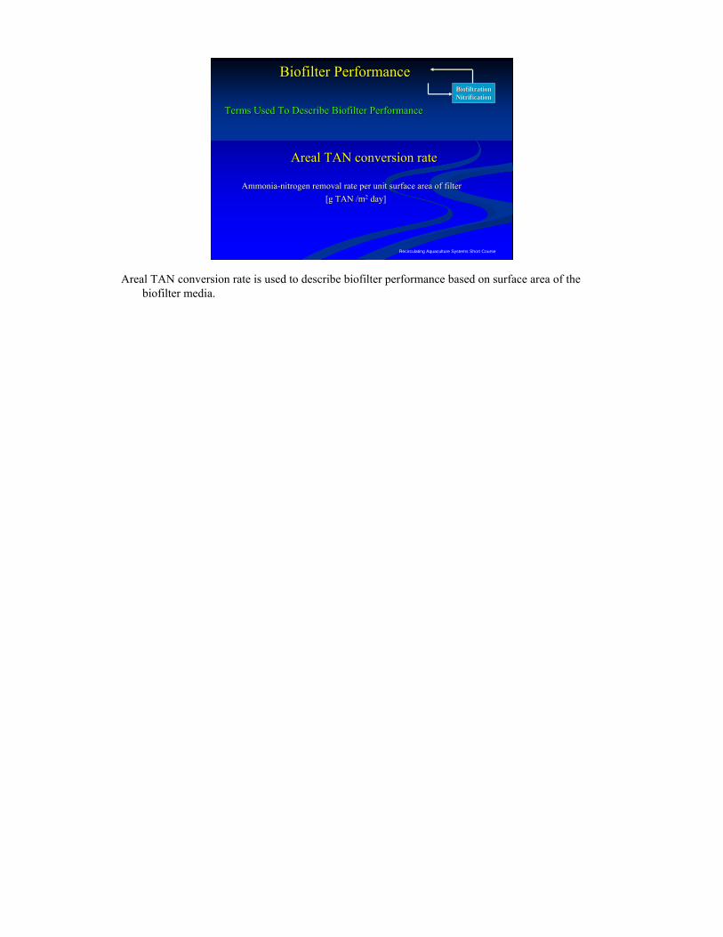
AmmoniaAmmonia--nitrogen removal rate per unit surface area of filternitrogen removal rate per unit surface area of filter[g TAN /m[g TAN /m22 day]day]
Biofilter PerformanceBiofilter Performance
Areal TAN conversion rate is used to describe biofilter performance based on surface area of the biofilter media.
Recirculating Aquaculture Systems Short Course
BiofiltrationBiofiltrationNitrificationNitrification
Biofilter PerformanceBiofilter Performance
Ammonia Assimilation RatesAmmonia Assimilation Rates
Media Type TAN ConversionBasis
TAN Conversion Rate
TAN Conversion Rate
(15 to 20 Deg. °C) (25 to 30 Deg. °C)
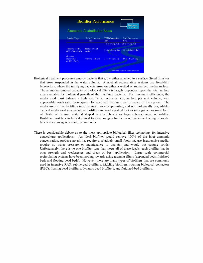
Trickling or RBC(100 – 300 m2/m3)
Surface area of media 0.2 to 1.0 g/m2 day 1.0 to 2.0 g/m2 day
Granular (bead/sand)(> 500 m2/m3)
Volume of media 0.6 to 0.7 kg/m3 day 1.0 to 1.5 kg/m3 day
Biological treatment processes employ bacteria that grow either attached to a surface (fixed films) or that grow suspended in the water column. Almost all recirculating systems use fixed-film bioreactors, where the nitrifying bacteria grow on either a wetted or submerged media surface. The ammonia removal capacity of biological filters is largely dependent upon the total surface area available for biological growth of the nitrifying bacteria. For maximum efficiency, the media used must balance a high specific surface area, i.e., surface per unit volume, with appreciable voids ratio (pore space) for adequate hydraulic performance of the system. The media used in the biofilters must be inert, non-compressible, and not biologically degradable. Typical media used in aquaculture biofilters are sand, crushed rock or river gravel, or some form of plastic or ceramic material shaped as small beads, or large spheres, rings, or saddles. Biofilters must be carefully designed to avoid oxygen limitation or excessive loading of solids, biochemical oxygen demand, or ammonia.
There is considerable debate as to the most appropriate biological filter technology for intensive aquaculture applications. An ideal biofilter would remove 100% of the inlet ammonia concentration, produce no nitrite, require a relatively small footprint, use inexpensive media, require no water pressure or maintenance to operate, and would not capture solids. Unfortunately, there is no one biofilter type that meets all of these ideals, each biofilter has its own strength and weaknesses and areas of best application. Large scale commercial recirculating systems have been moving towards using granular filters (expanded beds, fluidized beds and floating bead beds). However, there are many types of biofilters that are commonly used in intensive RAS: submerged biofilters, trickling biofilters, rotating biological contactors (RBC), floating bead biofilters, dynamic bead biofilters, and fluidized-bed biofilters.
Recirculating Aquaculture Systems Short Course
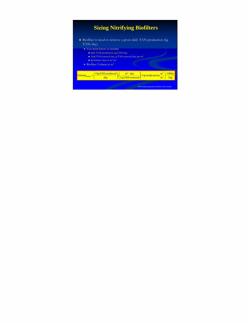
Biofilter is sized to remove a given daily TAN production (kg Biofilter is sized to remove a given daily TAN production (kg TAN/day).TAN/day).
You must know or assumeYou must know or assumedaily TAN production, kg TAN/day.daily TAN production, kg TAN/day.Arial TAN removal rate, g TAN removal/day per mArial TAN removal rate, g TAN removal/day per m22
Sp Surface Area in mSp Surface Area in m22/m/m33
Biofilter Volume in mBiofilter Volume in m33
Sizing Nitrifying BiofiltersSizing Nitrifying Biofilters
kgg
mmareasurfacesp
removedTANgdaym
dayproducedTANkgVolumeBiofilter 1
1000,##
#3
22
⋅⎟⎟⎠
⎞⎜⎜⎝
⎛⎟⎟⎠
⎞⎜⎜⎝
⎛ ⋅⋅⎟⎟⎠
⎞⎜⎜⎝
⎛=
Recirculating Aquaculture Systems Short Course
Biofilter Surface AreaBiofilter Surface Area
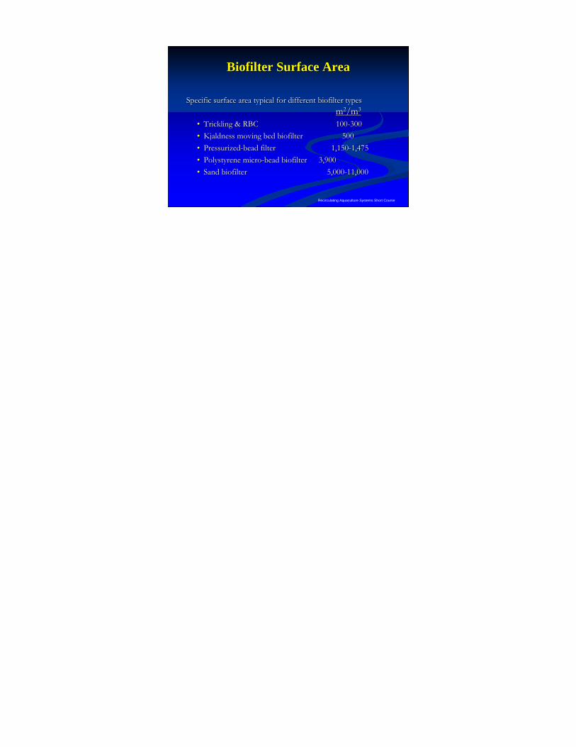
Specific surface area typical for different biofilter typesSpecific surface area typical for different biofilter typesmm22/m/m33
•• Trickling & RBCTrickling & RBC 100100--300300•• Kjaldness moving bed biofilterKjaldness moving bed biofilter 500500•• PressurizedPressurized--bead filterbead filter 1,1501,150--1,4751,475•• Polystyrene microPolystyrene micro--bead biofilterbead biofilter 3,9003,900•• Sand biofilterSand biofilter 5,0005,000--11,00011,000
Biofilter MediaBiofilter Media
Classified according to packing characteristics, i.e.,Classified according to packing characteristics, i.e.,•• Random packing:Random packing:
•• aggregate sand, crushed rock, or river gravel;aggregate sand, crushed rock, or river gravel;
•• plastic or ceramic beads, spheres, rings, or saddles;plastic or ceramic beads, spheres, rings, or saddles;
•• Structured packing:Structured packing:
•• plastic blocks of corrugated plates or tubes.plastic blocks of corrugated plates or tubes.
Recirculating Aquaculture Systems Short Course
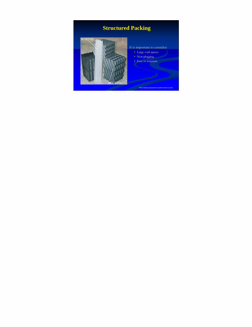
Structured PackingStructured Packing
It is important to consider:It is important to consider:•• Large void spacesLarge void spaces•• NonNon--pluggingplugging•• Easy to maintainEasy to maintain
ACCUPAC
NORPAC
Recirculating Aquaculture Systems Short Course
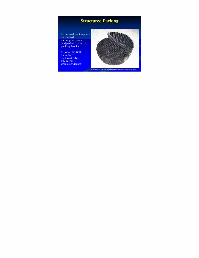
Structured PackingStructured Packing
Courtesy of LS Enterprises (FL)
Structured packings are not limited to rectangular tower designs! – circular cut packing blocks
AccuPac CF-3000:3 cm flute,95% void ratio,102 m2/m3 ,Crossflow design
Recirculating Aquaculture Systems Short Course
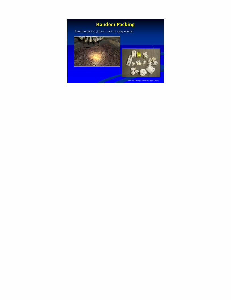
Random PackingRandom PackingRandom packing below a rotary spray nozzle.Random packing below a rotary spray nozzle.
Biofilter DesignBiofilter Design
To provide good performance and avoid solids plugging To provide good performance and avoid solids plugging & dead zones requires proper:& dead zones requires proper:
•• media selection, media selection, •• media support or retention mechanismsmedia support or retention mechanisms•• flow distribution,flow distribution,•• flow collection.flow collection.
Recirculating Aquaculture Systems Short Course
Biofilter ClassificationBiofilter Classification
Biofiltration
Fixed Film
Suspended GrowthHeterotrophic Bacteria
Autotrophic Bacteria
Submerged
Emergent
Fluidized Sand Filter
Moving Bed BioReactor
Downflow Microbead
Foam Filters
Floating Bead Bioclarifiers
Upflow Sand Filters
Expandable
Expanded
Packed
Submerged Rock
Trickling Tower
Rotating Biological Contractor
Plastic Packed Bed
Shell Filters
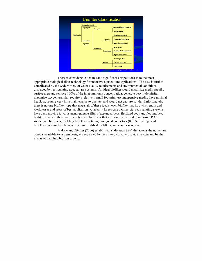
There is considerable debate (and significant competition) as to the most appropriate biological filter technology for intensive aquaculture applications. The task is further complicated by the wide variety of water quality requirements and environmental conditions displayed by recirculating aquaculture systems. An ideal biofilter would maximize media specific surface area and remove 100% of the inlet ammonia concentration, generate very little nitrite, maximize oxygen transfer, require a relatively small footprint, use inexpensive media, have minimal headloss, require very little maintenance to operate, and would not capture solids. Unfortunately, there is no one biofilter type that meets all of these ideals, each biofilter has its own strength and weaknesses and areas of best application. Currently large scale commercial recirculating systems have been moving towards using granular filters (expanded beds, fluidized beds and floating bead beds). However, there are many types of biofilters that are commonly used in intensive RAS: submerged biofilters, trickling biofilters, rotating biological contactors (RBC), floating bead biofilters, moving bed bioreactors, fluidized-bed biofilters, and countless others.
Malone and Pfeiffer (2006) established a “decision tree” that shows the numerous options available to system designers separated by the strategy used to provide oxygen and by the means of handling biofilm growth.
Recirculating Aquaculture Systems Short Course
Biofilter ClassificationBiofilter Classification
Biofiltration
Fixed Film
Suspended GrowthHeterotrophic Bacteria
Autotrophic Bacteria
microbial floc systems
fixed-film bioreactors
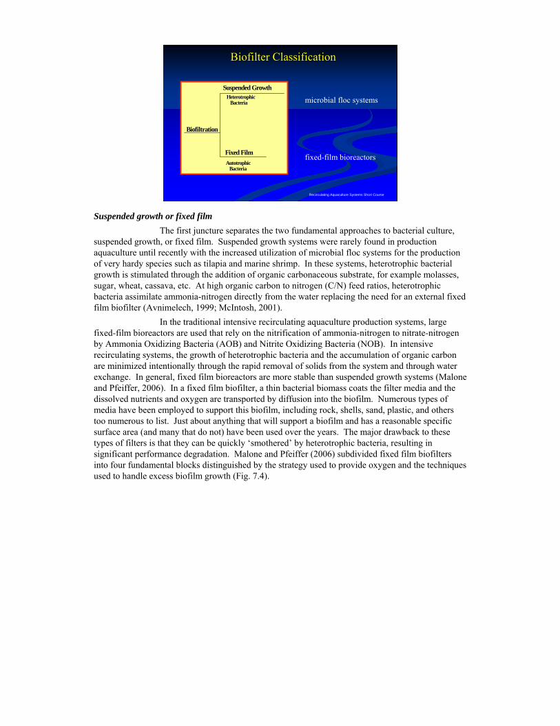
Suspended growth or fixed filmThe first juncture separates the two fundamental approaches to bacterial culture,
suspended growth, or fixed film. Suspended growth systems were rarely found in production aquaculture until recently with the increased utilization of microbial floc systems for the production of very hardy species such as tilapia and marine shrimp. In these systems, heterotrophic bacterial growth is stimulated through the addition of organic carbonaceous substrate, for example molasses, sugar, wheat, cassava, etc. At high organic carbon to nitrogen (C/N) feed ratios, heterotrophic bacteria assimilate ammonia-nitrogen directly from the water replacing the need for an external fixed film biofilter (Avnimelech, 1999; McIntosh, 2001).
In the traditional intensive recirculating aquaculture production systems, large fixed-film bioreactors are used that rely on the nitrification of ammonia-nitrogen to nitrate-nitrogen by Ammonia Oxidizing Bacteria (AOB) and Nitrite Oxidizing Bacteria (NOB). In intensive recirculating systems, the growth of heterotrophic bacteria and the accumulation of organic carbon are minimized intentionally through the rapid removal of solids from the system and through water exchange. In general, fixed film bioreactors are more stable than suspended growth systems (Malone and Pfeiffer, 2006). In a fixed film biofilter, a thin bacterial biomass coats the filter media and the dissolved nutrients and oxygen are transported by diffusion into the biofilm. Numerous types of media have been employed to support this biofilm, including rock, shells, sand, plastic, and others too numerous to list. Just about anything that will support a biofilm and has a reasonable specific surface area (and many that do not) have been used over the years. The major drawback to these types of filters is that they can be quickly ‘smothered’ by heterotrophic bacteria, resulting in significant performance degradation. Malone and Pfeiffer (2006) subdivided fixed film biofilters into four fundamental blocks distinguished by the strategy used to provide oxygen and the techniques used to handle excess biofilm growth (Fig. 7.4).
Recirculating Aquaculture Systems Short Course
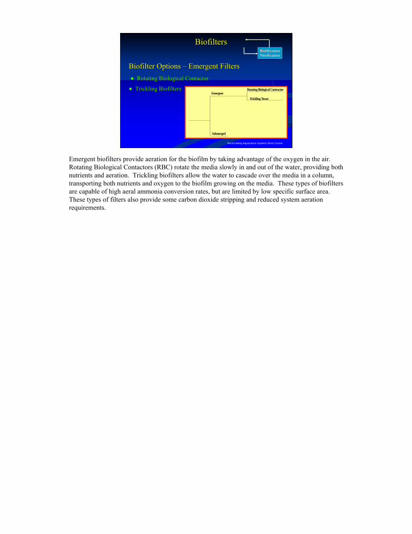
Biofilter Options Biofilter Options –– Emergent FiltersEmergent Filters●● Rotating Biological ContactorRotating Biological Contactor
●● Trickling BiofiltersTrickling Biofilters
BiofiltrationBiofiltrationNitrificationNitrification
BiofiltersBiofilters
Submerged
EmergentTrickling Tower
Rotating Biological Contractor
Emergent biofilters provide aeration for the biofilm by taking advantage of the oxygen in the air. Rotating Biological Contactors (RBC) rotate the media slowly in and out of the water, providing both nutrients and aeration. Trickling biofilters allow the water to cascade over the media in a column, transporting both nutrients and oxygen to the biofilm growing on the media. These types of biofilters are capable of high aeral ammonia conversion rates, but are limited by low specific surface area. These types of filters also provide some carbon dioxide stripping and reduced system aeration requirements.
Recirculating Aquaculture Systems Short Course
Rotating Rotating Biological Biological ContactorContactor
BiofiltrationBiofiltrationNitrificationNitrification
BiofiltersBiofilters
supportshaft
rotatingmedia"drum"
influent
effluent
gear motor& chain drive
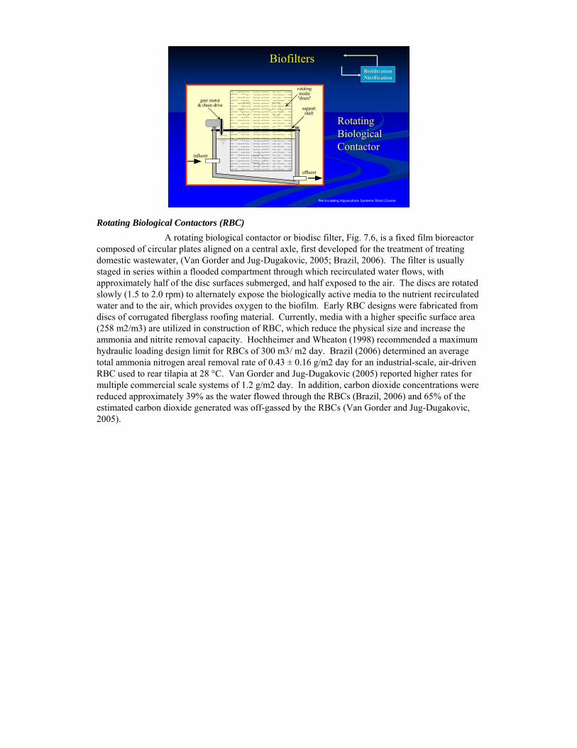
Rotating Biological Contactors (RBC)A rotating biological contactor or biodisc filter, Fig. 7.6, is a fixed film bioreactor
composed of circular plates aligned on a central axle, first developed for the treatment of treating domestic wastewater, (Van Gorder and Jug-Dugakovic, 2005; Brazil, 2006). The filter is usually staged in series within a flooded compartment through which recirculated water flows, with approximately half of the disc surfaces submerged, and half exposed to the air. The discs are rotated slowly (1.5 to 2.0 rpm) to alternately expose the biologically active media to the nutrient recirculated water and to the air, which provides oxygen to the biofilm. Early RBC designs were fabricated from discs of corrugated fiberglass roofing material. Currently, media with a higher specific surface area (258 m2/m3) are utilized in construction of RBC, which reduce the physical size and increase the ammonia and nitrite removal capacity. Hochheimer and Wheaton (1998) recommended a maximum hydraulic loading design limit for RBCs of 300 m3/ m2 day. Brazil (2006) determined an average total ammonia nitrogen areal removal rate of 0.43 ± 0.16 g/m2 day for an industrial-scale, air-driven RBC used to rear tilapia at 28 °C. Van Gorder and Jug-Dugakovic (2005) reported higher rates for multiple commercial scale systems of 1.2 g/m2 day. In addition, carbon dioxide concentrations were reduced approximately 39% as the water flowed through the RBCs (Brazil, 2006) and 65% of the estimated carbon dioxide generated was off-gassed by the RBCs (Van Gorder and Jug-Dugakovic, 2005).
Recirculating Aquaculture Systems Short Course
Rotating Biological ContactorRotating Biological ContactorBiofiltrationBiofiltrationNitrificationNitrification
BiofiltersBiofilters
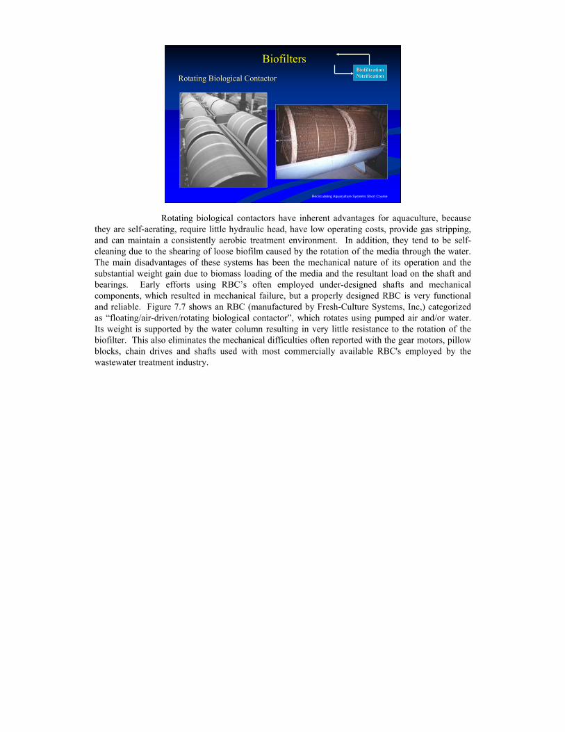
Rotating biological contactors have inherent advantages for aquaculture, because they are self-aerating, require little hydraulic head, have low operating costs, provide gas stripping, and can maintain a consistently aerobic treatment environment. In addition, they tend to be self-cleaning due to the shearing of loose biofilm caused by the rotation of the media through the water. The main disadvantages of these systems has been the mechanical nature of its operation and the substantial weight gain due to biomass loading of the media and the resultant load on the shaft and bearings. Early efforts using RBC’s often employed under-designed shafts and mechanical components, which resulted in mechanical failure, but a properly designed RBC is very functional and reliable. Figure 7.7 shows an RBC (manufactured by Fresh-Culture Systems, Inc,) categorized as “floating/air-driven/rotating biological contactor”, which rotates using pumped air and/or water. Its weight is supported by the water column resulting in very little resistance to the rotation of the biofilter. This also eliminates the mechanical difficulties often reported with the gear motors, pillow blocks, chain drives and shafts used with most commercially available RBC's employed by the wastewater treatment industry.
Recirculating Aquaculture Systems Short Course
BiofiltrationBiofiltrationNitrificationNitrification
BiofiltersBiofilters
mediasupportplate
airventilation
pipe
influent with flowdistribution header
effluent
media Trickling BiofiltersTrickling Biofilters
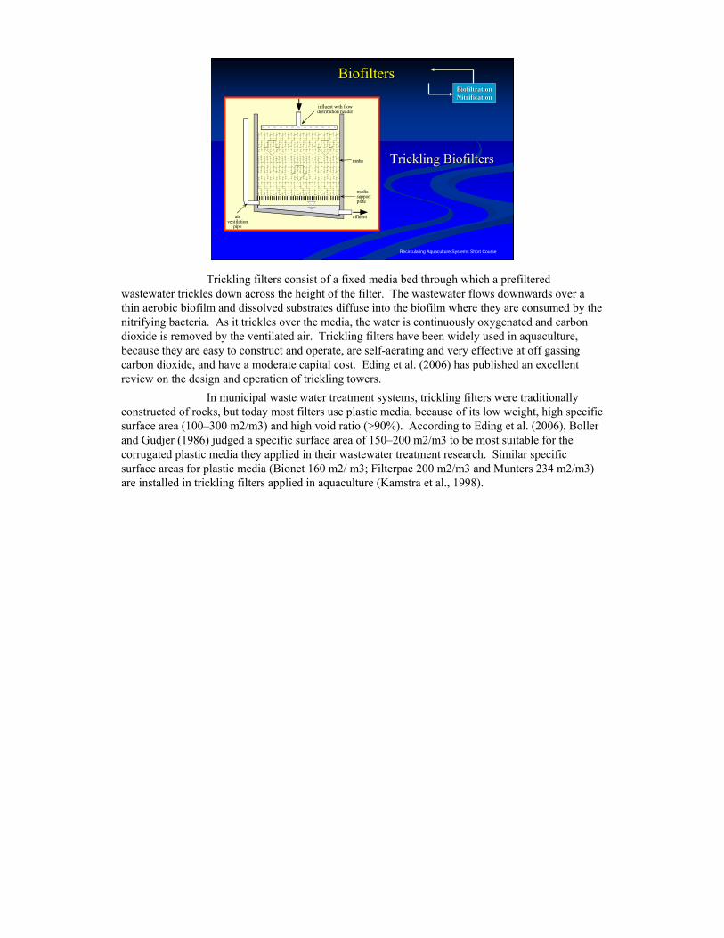
Trickling filters consist of a fixed media bed through which a prefiltered wastewater trickles down across the height of the filter. The wastewater flows downwards over a thin aerobic biofilm and dissolved substrates diffuse into the biofilm where they are consumed by the nitrifying bacteria. As it trickles over the media, the water is continuously oxygenated and carbon dioxide is removed by the ventilated air. Trickling filters have been widely used in aquaculture, because they are easy to construct and operate, are self-aerating and very effective at off gassing carbon dioxide, and have a moderate capital cost. Eding et al. (2006) has published an excellent review on the design and operation of trickling towers.
In municipal waste water treatment systems, trickling filters were traditionally constructed of rocks, but today most filters use plastic media, because of its low weight, high specific surface area (100–300 m2/m3) and high void ratio (>90%). According to Eding et al. (2006), Boller and Gudjer (1986) judged a specific surface area of 150–200 m2/m3 to be most suitable for the corrugated plastic media they applied in their wastewater treatment research. Similar specific surface areas for plastic media (Bionet 160 m2/ m3; Filterpac 200 m2/m3 and Munters 234 m2/m3) are installed in trickling filters applied in aquaculture (Kamstra et al., 1998).
Recirculating Aquaculture Systems Short Course
Trickling Biofilters Trickling Biofilters –– MediaMediaBiofiltrationBiofiltrationNitrificationNitrification
BiofiltersBiofilters
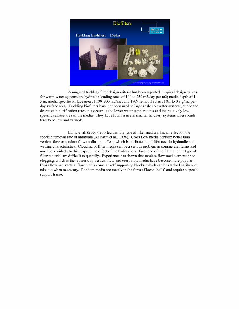
A range of trickling filter design criteria has been reported. Typical design values for warm water systems are hydraulic loading rates of 100 to 250 m3/day per m2; media depth of 1–5 m; media specific surface area of 100–300 m2/m3; and TAN removal rates of 0.1 to 0.9 g/m2 per day surface area. Trickling biofilters have not been used in large scale coldwater systems, due to the decrease in nitrification rates that occurs at the lower water temperatures and the relatively low specific surface area of the media. They have found a use in smaller hatchery systems where loads tend to be low and variable.
Eding et al. (2006) reported that the type of filter medium has an effect on the specific removal rate of ammonia (Kamstra et al., 1998). Cross flow media perform better than vertical flow or random flow media—an effect, which is attributed to, differences in hydraulic and wetting characteristics. Clogging of filter media can be a serious problem in commercial farms and must be avoided. In this respect, the effect of the hydraulic surface load of the filter and the type of filter material are difficult to quantify. Experience has shown that random flow media are prone to clogging, which is the reason why vertical flow and cross flow media have become more popular. Cross flow and vertical flow media come as self supporting blocks, which can be stacked easily and take out when necessary. Random media are mostly in the form of loose ‘balls’ and require a special support frame.
Recirculating Aquaculture Systems Short Course
Trickling Biofilters Trickling Biofilters –– Spray BarSpray Bar
BiofiltrationBiofiltrationNitrificationNitrification
BiofiltersBiofilters
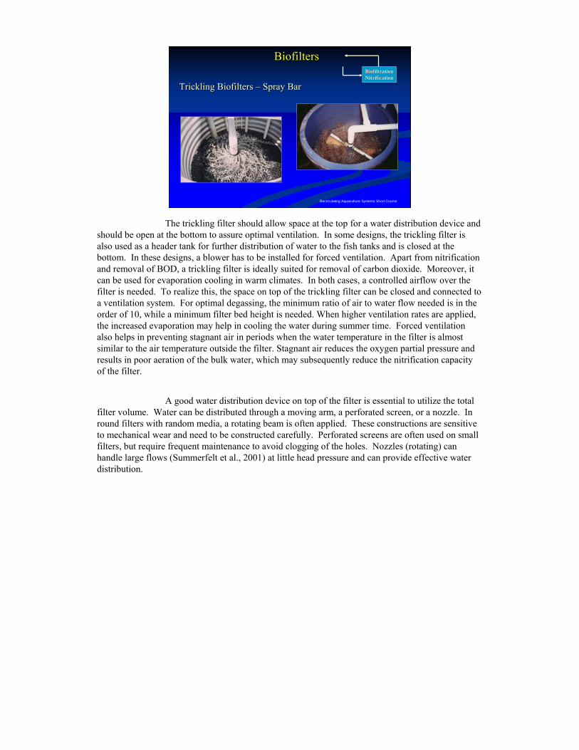
The trickling filter should allow space at the top for a water distribution device and should be open at the bottom to assure optimal ventilation. In some designs, the trickling filter is also used as a header tank for further distribution of water to the fish tanks and is closed at the bottom. In these designs, a blower has to be installed for forced ventilation. Apart from nitrification and removal of BOD, a trickling filter is ideally suited for removal of carbon dioxide. Moreover, it can be used for evaporation cooling in warm climates. In both cases, a controlled airflow over the filter is needed. To realize this, the space on top of the trickling filter can be closed and connected to a ventilation system. For optimal degassing, the minimum ratio of air to water flow needed is in the order of 10, while a minimum filter bed height is needed. When higher ventilation rates are applied, the increased evaporation may help in cooling the water during summer time. Forced ventilation also helps in preventing stagnant air in periods when the water temperature in the filter is almost similar to the air temperature outside the filter. Stagnant air reduces the oxygen partial pressure and results in poor aeration of the bulk water, which may subsequently reduce the nitrification capacity of the filter.
A good water distribution device on top of the filter is essential to utilize the total filter volume. Water can be distributed through a moving arm, a perforated screen, or a nozzle. In round filters with random media, a rotating beam is often applied. These constructions are sensitive to mechanical wear and need to be constructed carefully. Perforated screens are often used on small filters, but require frequent maintenance to avoid clogging of the holes. Nozzles (rotating) can handle large flows (Summerfelt et al., 2001) at little head pressure and can provide effective water distribution.
Recirculating Aquaculture Systems Short Course
Biofilter Options Biofilter Options ––Submerged Submerged BiofiltersBiofilters
BiofiltrationBiofiltrationNitrificationNitrification
BiofiltersBiofilters
Shell Filters
Plastic Packed Bed
Submerged Rock
Packed
Expanded
Expandable
Upflow Sand Filters
Floating Bead Bioclarifiers
Foam Filters
Downflow Microbead
Moving Bed BioReactor
Fluidized Sand Filter
Submerged
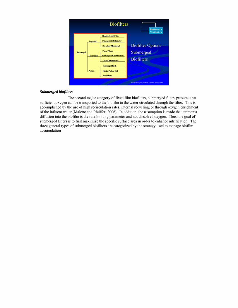
Submerged biofiltersThe second major category of fixed film biofilters, submerged filters presume that
sufficient oxygen can be transported to the biofilm in the water circulated through the filter. This is accomplished by the use of high recirculation rates, internal recycling, or through oxygen enrichment of the influent water (Malone and Pfeiffer, 2006). In addition, the assumption is made that ammonia diffusion into the biofilm is the rate limiting parameter and not dissolved oxygen. Thus, the goal of submerged filters is to first maximize the specific surface area in order to enhance nitrification. The three general types of submerged biofilters are categorized by the strategy used to manage biofilm accumulation
Recirculating Aquaculture Systems Short Course
Submerged Biofilters Submerged Biofilters –– Static Packed BedStatic Packed Bed
BiofiltrationBiofiltrationNitrificationNitrification
BiofiltersBiofilters
Gravel Bed BiofilterGravel Bed Biofilter
Random Packed Plastic MediaRandom Packed Plastic Media
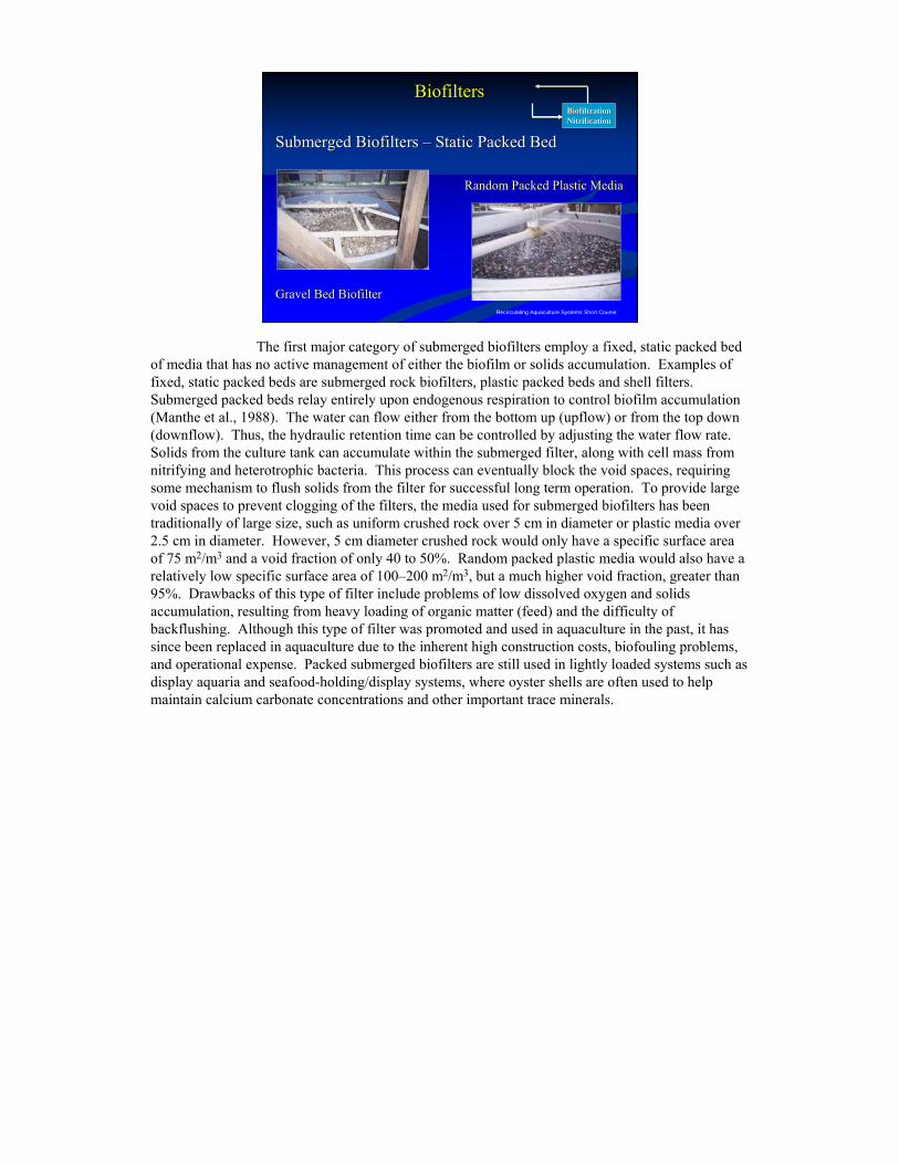
The first major category of submerged biofilters employ a fixed, static packed bed of media that has no active management of either the biofilm or solids accumulation. Examples of fixed, static packed beds are submerged rock biofilters, plastic packed beds and shell filters. Submerged packed beds relay entirely upon endogenous respiration to control biofilm accumulation (Manthe et al., 1988). The water can flow either from the bottom up (upflow) or from the top down (downflow). Thus, the hydraulic retention time can be controlled by adjusting the water flow rate. Solids from the culture tank can accumulate within the submerged filter, along with cell mass from nitrifying and heterotrophic bacteria. This process can eventually block the void spaces, requiring some mechanism to flush solids from the filter for successful long term operation. To provide large void spaces to prevent clogging of the filters, the media used for submerged biofilters has been traditionally of large size, such as uniform crushed rock over 5 cm in diameter or plastic media over 2.5 cm in diameter. However, 5 cm diameter crushed rock would only have a specific surface area of 75 m2/m3 and a void fraction of only 40 to 50%. Random packed plastic media would also have a relatively low specific surface area of 100–200 m2/m3, but a much higher void fraction, greater than 95%. Drawbacks of this type of filter include problems of low dissolved oxygen and solids accumulation, resulting from heavy loading of organic matter (feed) and the difficulty of backflushing. Although this type of filter was promoted and used in aquaculture in the past, it has since been replaced in aquaculture due to the inherent high construction costs, biofouling problems, and operational expense. Packed submerged biofilters are still used in lightly loaded systems such as display aquaria and seafood-holding/display systems, where oyster shells are often used to help maintain calcium carbonate concentrations and other important trace minerals.
Recirculating Aquaculture Systems Short Course
Submerged Biofilters Submerged Biofilters -- Expandable FiltersExpandable Filters
●● Upflow Sand FiltersUpflow Sand Filters
●● FloatingFloating--Bead BioclarifiersBead Bioclarifiers
BiofiltrationBiofiltrationNitrificationNitrification
BiofiltersBiofilters
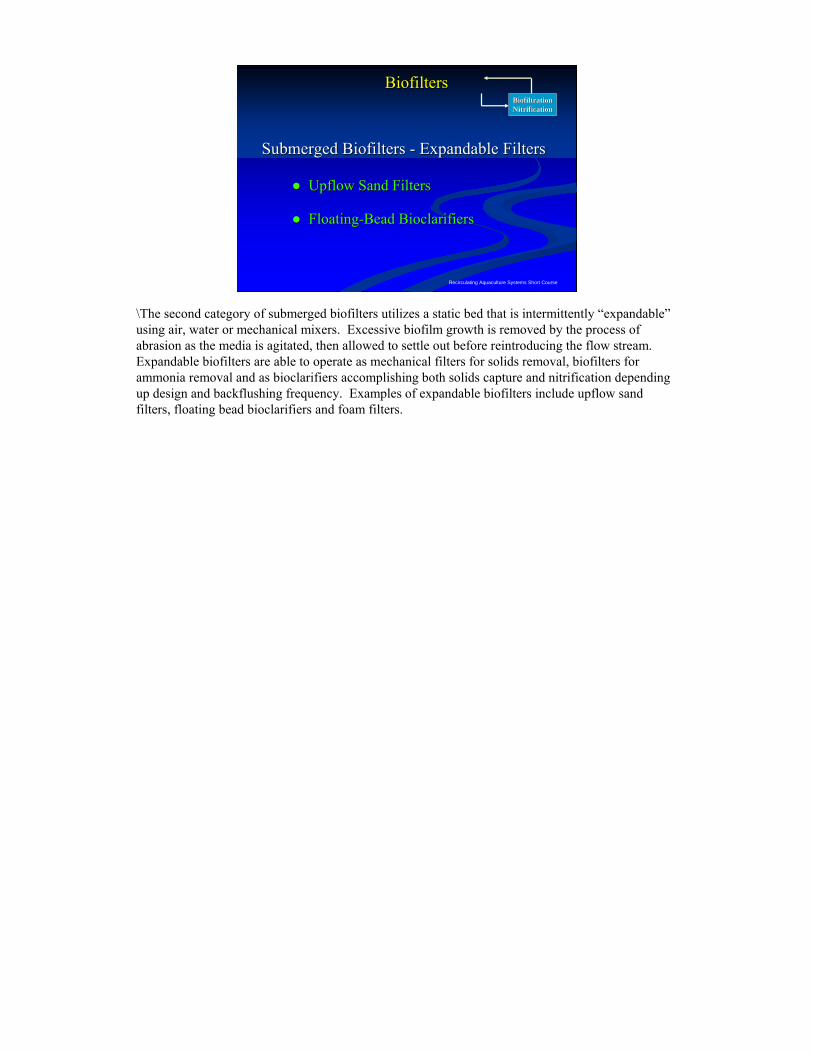
\The second category of submerged biofilters utilizes a static bed that is intermittently “expandable”using air, water or mechanical mixers. Excessive biofilm growth is removed by the process of abrasion as the media is agitated, then allowed to settle out before reintroducing the flow stream. Expandable biofilters are able to operate as mechanical filters for solids removal, biofilters for ammonia removal and as bioclarifiers accomplishing both solids capture and nitrification depending up design and backflushing frequency. Examples of expandable biofilters include upflow sand filters, floating bead bioclarifiers and foam filters.
Recirculating Aquaculture Systems Short Course
Up Flow Up Flow Sand FiltersSand Filters
BiofiltrationBiofiltrationNitrificationNitrification
BiofiltersBiofilters
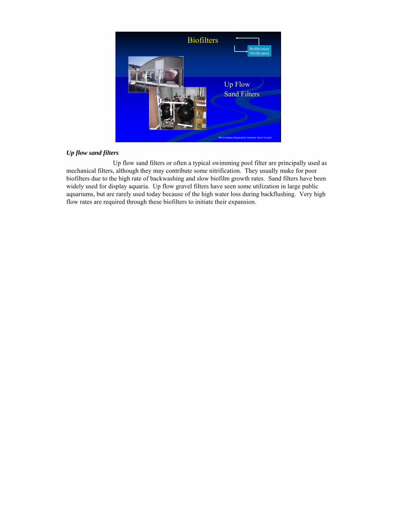
Up flow sand filtersUp flow sand filters or often a typical swimming pool filter are principally used as
mechanical filters, although they may contribute some nitrification. They usually make for poor biofilters due to the high rate of backwashing and slow biofilm growth rates. Sand filters have been widely used for display aquaria. Up flow gravel filters have seen some utilization in large public aquariums, but are rarely used today because of the high water loss during backflushing. Very high flow rates are required through these biofilters to initiate their expansion.
Recirculating Aquaculture Systems Short Course
Floating Bead Floating Bead BioclarifiersBioclarifiers
BiofiltrationBiofiltrationNitrificationNitrification
BiofiltersBiofilters
Propeller-washed Bioclarifiers
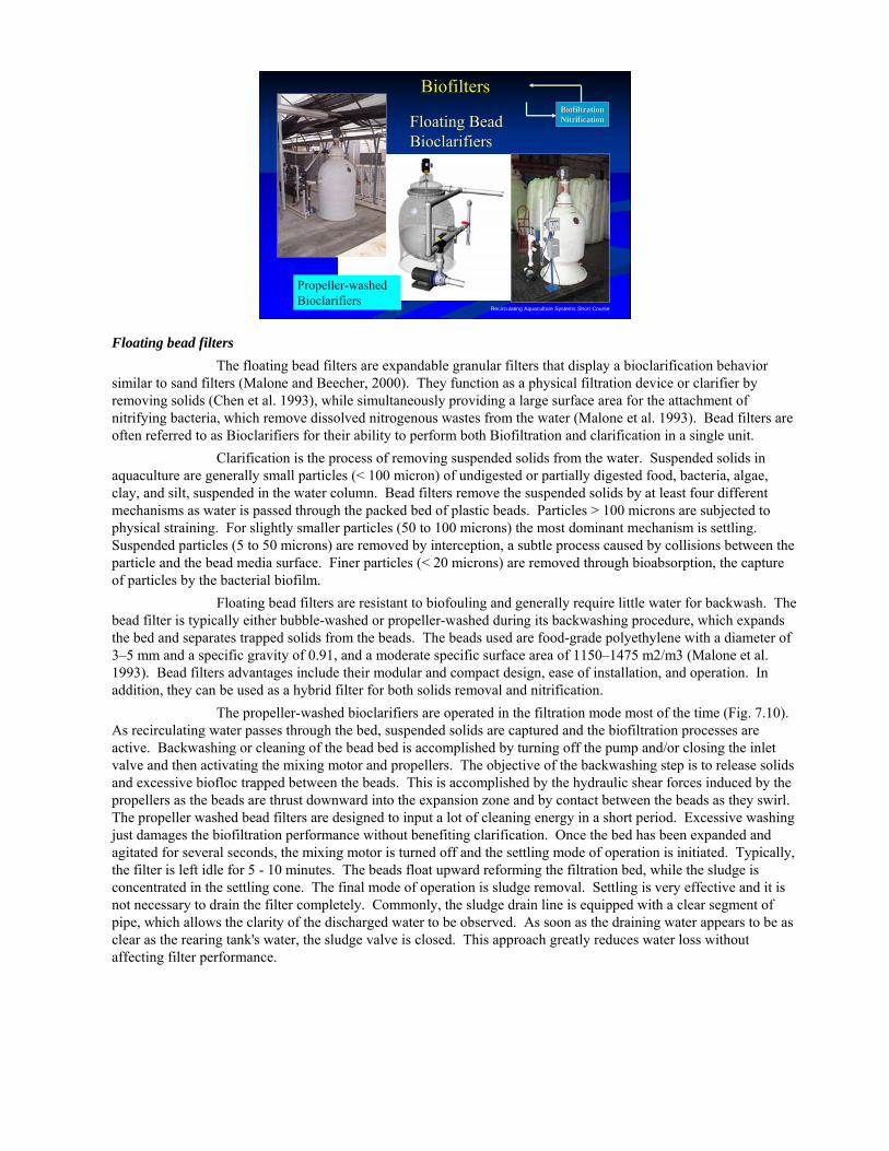
Floating bead filtersThe floating bead filters are expandable granular filters that display a bioclarification behavior
similar to sand filters (Malone and Beecher, 2000). They function as a physical filtration device or clarifier by removing solids (Chen et al. 1993), while simultaneously providing a large surface area for the attachment of nitrifying bacteria, which remove dissolved nitrogenous wastes from the water (Malone et al. 1993). Bead filters are often referred to as Bioclarifiers for their ability to perform both Biofiltration and clarification in a single unit.
Clarification is the process of removing suspended solids from the water. Suspended solids in aquaculture are generally small particles (< 100 micron) of undigested or partially digested food, bacteria, algae, clay, and silt, suspended in the water column. Bead filters remove the suspended solids by at least four different mechanisms as water is passed through the packed bed of plastic beads. Particles > 100 microns are subjected to physical straining. For slightly smaller particles (50 to 100 microns) the most dominant mechanism is settling. Suspended particles (5 to 50 microns) are removed by interception, a subtle process caused by collisions between the particle and the bead media surface. Finer particles (< 20 microns) are removed through bioabsorption, the capture of particles by the bacterial biofilm.
Floating bead filters are resistant to biofouling and generally require little water for backwash. The bead filter is typically either bubble-washed or propeller-washed during its backwashing procedure, which expands the bed and separates trapped solids from the beads. The beads used are food-grade polyethylene with a diameter of 3–5 mm and a specific gravity of 0.91, and a moderate specific surface area of 1150–1475 m2/m3 (Malone et al. 1993). Bead filters advantages include their modular and compact design, ease of installation, and operation. In addition, they can be used as a hybrid filter for both solids removal and nitrification.
The propeller-washed bioclarifiers are operated in the filtration mode most of the time (Fig. 7.10). As recirculating water passes through the bed, suspended solids are captured and the biofiltration processes are active. Backwashing or cleaning of the bead bed is accomplished by turning off the pump and/or closing the inlet valve and then activating the mixing motor and propellers. The objective of the backwashing step is to release solids and excessive biofloc trapped between the beads. This is accomplished by the hydraulic shear forces induced by the propellers as the beads are thrust downward into the expansion zone and by contact between the beads as they swirl. The propeller washed bead filters are designed to input a lot of cleaning energy in a short period. Excessive washing just damages the biofiltration performance without benefiting clarification. Once the bed has been expanded and agitated for several seconds, the mixing motor is turned off and the settling mode of operation is initiated. Typically, the filter is left idle for 5 - 10 minutes. The beads float upward reforming the filtration bed, while the sludge is concentrated in the settling cone. The final mode of operation is sludge removal. Settling is very effective and it is not necessary to drain the filter completely. Commonly, the sludge drain line is equipped with a clear segment of pipe, which allows the clarity of the discharged water to be observed. As soon as the draining water appears to be as clear as the rearing tank's water, the sludge valve is closed. This approach greatly reduces water loss without affecting filter performance.
Recirculating Aquaculture Systems Short Course
Floating Floating Bead Bead BioclarifiersBioclarifiers
BiofiltrationBiofiltrationNitrificationNitrification
BiofiltersBiofilters
Bubble-washed Bioclarifiers
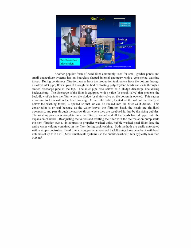
Another popular form of bead filter commonly used for small garden ponds and small aquaculture systems has an hourglass shaped internal geometry with a constricted washing throat. During continuous filtration, water from the production tank enters from the bottom through a slotted inlet pipe, flows upward through the bed of floating polyethylene beads and exits through a slotted discharge pipe at the top. The inlet pipe also serves as a sludge discharge line during backwashing. The discharge of the filter is equipped with a valve (or check valve) that prevents the back-flow of air into the filter when the sludge (or drain) valve on the bottom is opened. This causes a vacuum to form within the filter housing. An air inlet valve, located on the side of the filter just below the washing throat, is opened so that air can be sucked into the filter as it drains. This constriction is critical because as the water leaves the filtration head, the beads are fluidized downward, and pass through the narrow throat where they are scrubbed further by the rising bubbles. The washing process is complete once the filter is drained and all the beads have dropped into the expansion chamber. Readjusting the valves and refilling the filter with the recirculation pump starts the next filtration cycle. In contrast to propeller-washed units, bubble-washed bead filters lose the entire water volume contained in the filter during backwashing. Both methods are easily automated with a simple controller. Bead filters using propeller-washed backflushing have been built with bead volumes of up to 2.8 m3. Most small-scale systems use the bubble-washed filters, typically less than 0.28 m3.
Recirculating Aquaculture Systems Short Course
Floating Bead Floating Bead BioclarifiersBioclarifiers
BiofiltrationBiofiltrationNitrificationNitrification
BiofiltersBiofilters
PolyGeyser Bead Filter
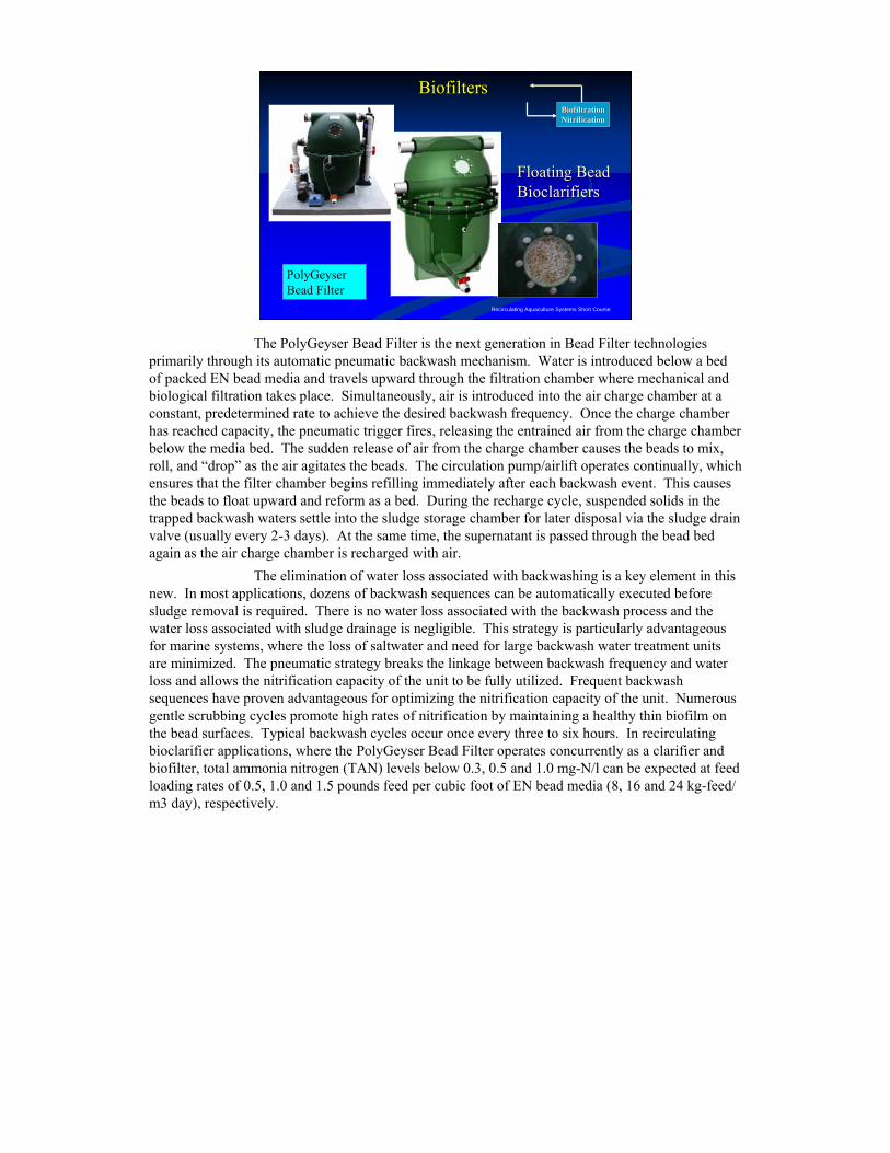
The PolyGeyser Bead Filter is the next generation in Bead Filter technologies primarily through its automatic pneumatic backwash mechanism. Water is introduced below a bed of packed EN bead media and travels upward through the filtration chamber where mechanical and biological filtration takes place. Simultaneously, air is introduced into the air charge chamber at a constant, predetermined rate to achieve the desired backwash frequency. Once the charge chamber has reached capacity, the pneumatic trigger fires, releasing the entrained air from the charge chamber below the media bed. The sudden release of air from the charge chamber causes the beads to mix, roll, and “drop” as the air agitates the beads. The circulation pump/airlift operates continually, which ensures that the filter chamber begins refilling immediately after each backwash event. This causes the beads to float upward and reform as a bed. During the recharge cycle, suspended solids in the trapped backwash waters settle into the sludge storage chamber for later disposal via the sludge drain valve (usually every 2-3 days). At the same time, the supernatant is passed through the bead bed again as the air charge chamber is recharged with air.
The elimination of water loss associated with backwashing is a key element in this new. In most applications, dozens of backwash sequences can be automatically executed before sludge removal is required. There is no water loss associated with the backwash process and the water loss associated with sludge drainage is negligible. This strategy is particularly advantageous for marine systems, where the loss of saltwater and need for large backwash water treatment units are minimized. The pneumatic strategy breaks the linkage between backwash frequency and water loss and allows the nitrification capacity of the unit to be fully utilized. Frequent backwash sequences have proven advantageous for optimizing the nitrification capacity of the unit. Numerous gentle scrubbing cycles promote high rates of nitrification by maintaining a healthy thin biofilm on the bead surfaces. Typical backwash cycles occur once every three to six hours. In recirculating bioclarifier applications, where the PolyGeyser Bead Filter operates concurrently as a clarifier and biofilter, total ammonia nitrogen (TAN) levels below 0.3, 0.5 and 1.0 mg-N/l can be expected at feed loading rates of 0.5, 1.0 and 1.5 pounds feed per cubic foot of EN bead media (8, 16 and 24 kg-feed/ m3 day), respectively.
Recirculating Aquaculture Systems Short Course
BiofiltrationBiofiltrationNitrificationNitrification
BiofiltersBiofilters
Submerged Biofilters Submerged Biofilters –– Expanded BedExpanded Bed
•• FluidizedFluidized--Sand Beds FiltersSand Beds Filters•• Microbead FiltersMicrobead Filters•• Moving Bed BioReactorsMoving Bed BioReactors
maintains the media in continuous expansion
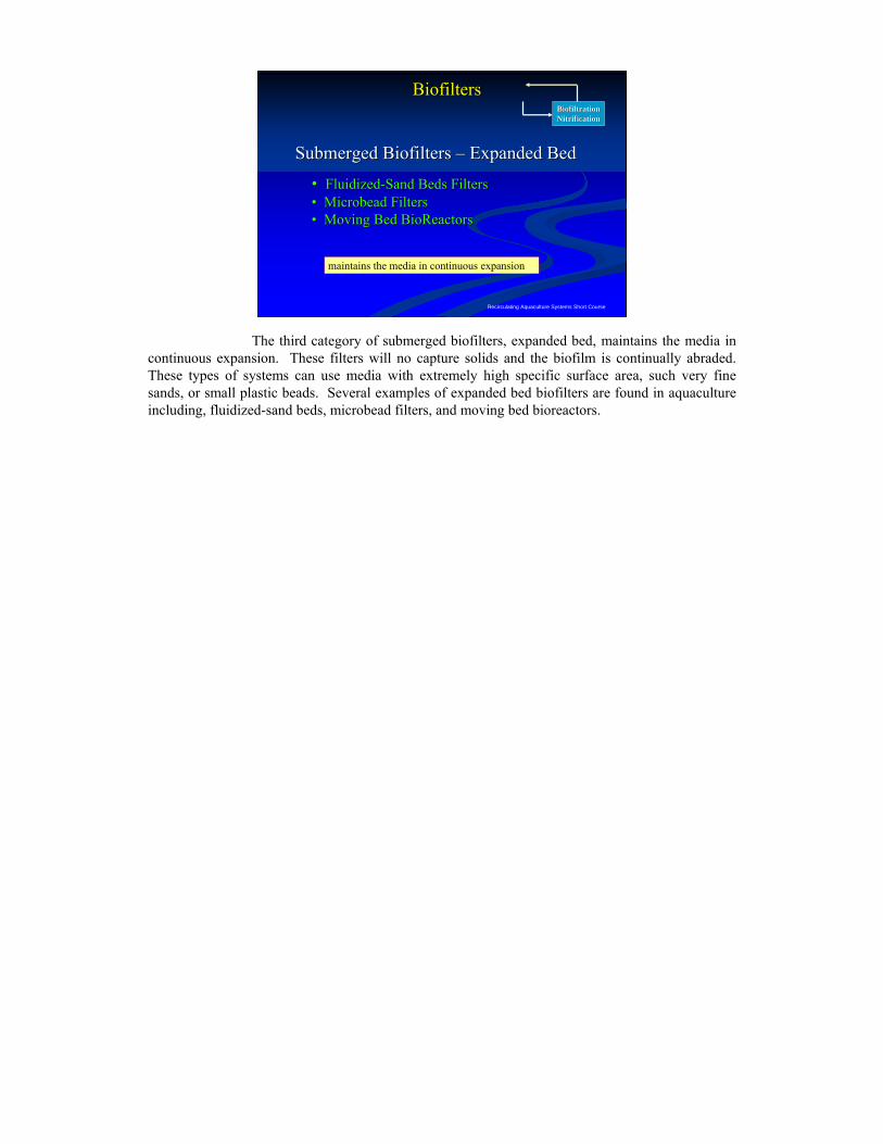
The third category of submerged biofilters, expanded bed, maintains the media in continuous expansion. These filters will no capture solids and the biofilm is continually abraded. These types of systems can use media with extremely high specific surface area, such very fine sands, or small plastic beads. Several examples of expanded bed biofilters are found in aquaculture including, fluidized-sand beds, microbead filters, and moving bed bioreactors.
Recirculating Aquaculture Systems Short Course
Upflow Sand BiofiltersUpflow Sand Biofilters
BiofiltrationBiofiltrationNitrificationNitrification
Expanded Sand
Influent
Effluent
Orifices in distribution pipes
Manifold
Check Valve
Ball Valve
Clean outsClean out
BiofiltersBiofilters
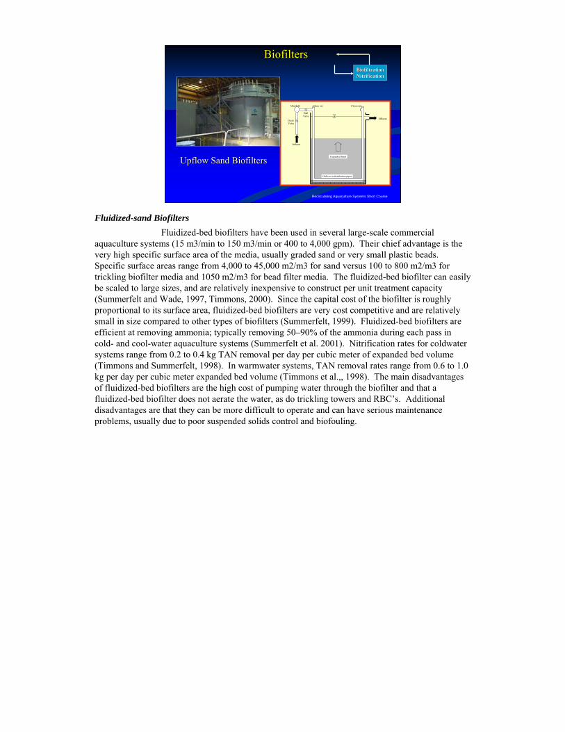
Fluidized-sand BiofiltersFluidized-bed biofilters have been used in several large-scale commercial
aquaculture systems (15 m3/min to 150 m3/min or 400 to 4,000 gpm). Their chief advantage is the very high specific surface area of the media, usually graded sand or very small plastic beads. Specific surface areas range from 4,000 to 45,000 m2/m3 for sand versus 100 to 800 m2/m3 for trickling biofilter media and 1050 m2/m3 for bead filter media. The fluidized-bed biofilter can easily be scaled to large sizes, and are relatively inexpensive to construct per unit treatment capacity (Summerfelt and Wade, 1997, Timmons, 2000). Since the capital cost of the biofilter is roughly proportional to its surface area, fluidized-bed biofilters are very cost competitive and are relatively small in size compared to other types of biofilters (Summerfelt, 1999). Fluidized-bed biofilters are efficient at removing ammonia; typically removing 50–90% of the ammonia during each pass in cold- and cool-water aquaculture systems (Summerfelt et al. 2001). Nitrification rates for coldwater systems range from 0.2 to 0.4 kg TAN removal per day per cubic meter of expanded bed volume (Timmons and Summerfelt, 1998). In warmwater systems, TAN removal rates range from 0.6 to 1.0 kg per day per cubic meter expanded bed volume (Timmons et al.,, 1998). The main disadvantages of fluidized-bed biofilters are the high cost of pumping water through the biofilter and that a fluidized-bed biofilter does not aerate the water, as do trickling towers and RBC’s. Additional disadvantages are that they can be more difficult to operate and can have serious maintenance problems, usually due to poor suspended solids control and biofouling.
Recirculating Aquaculture Systems Short Course
BiofiltrationBiofiltrationNitrificationNitrification
BiofiltersBiofilters
Flow Distribution Mechanism
Upflow Sand BiofiltersUpflow Sand Biofilters
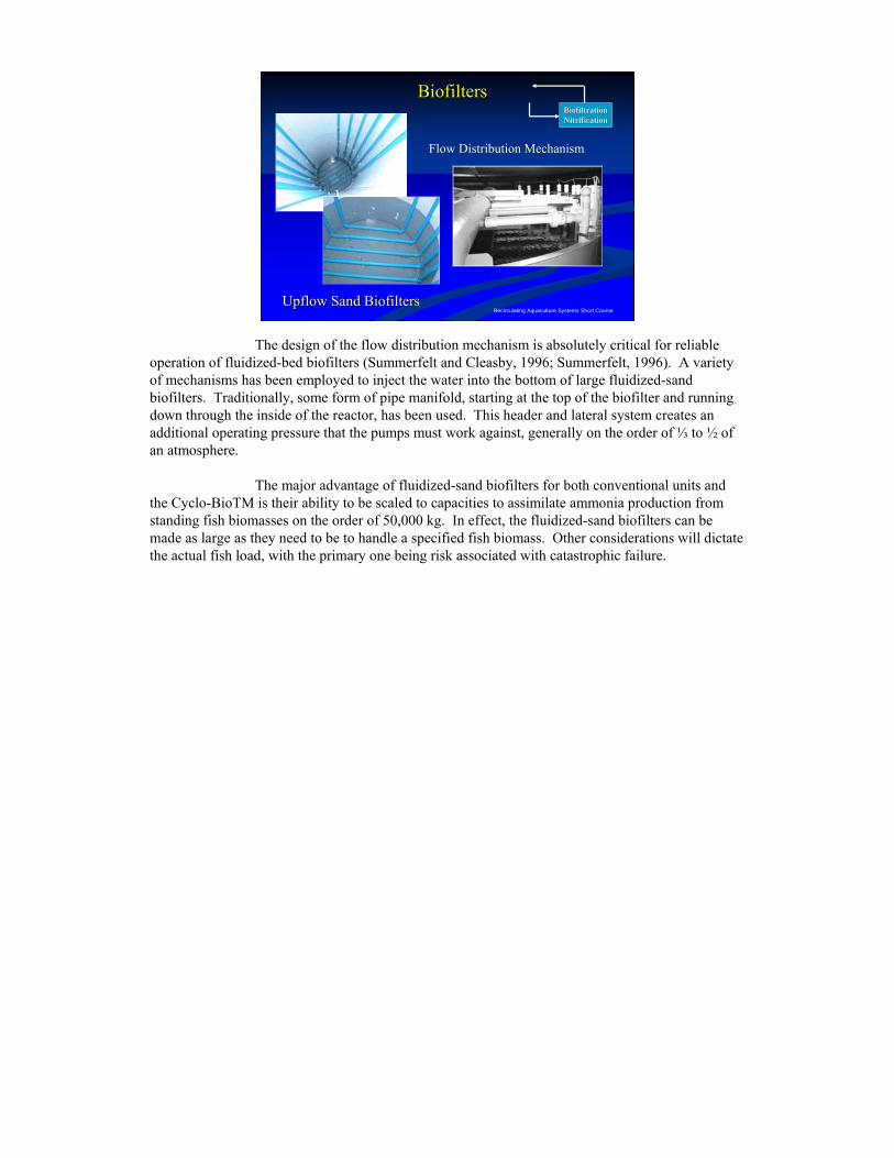
The design of the flow distribution mechanism is absolutely critical for reliable operation of fluidized-bed biofilters (Summerfelt and Cleasby, 1996; Summerfelt, 1996). A variety of mechanisms has been employed to inject the water into the bottom of large fluidized-sand biofilters. Traditionally, some form of pipe manifold, starting at the top of the biofilter and running down through the inside of the reactor, has been used. This header and lateral system creates an additional operating pressure that the pumps must work against, generally on the order of ⅓ to ½ of an atmosphere.
The major advantage of fluidized-sand biofilters for both conventional units and the Cyclo-BioTM is their ability to be scaled to capacities to assimilate ammonia production from standing fish biomasses on the order of 50,000 kg. In effect, the fluidized-sand biofilters can be made as large as they need to be to handle a specified fish biomass. Other considerations will dictate the actual fish load, with the primary one being risk associated with catastrophic failure.
Recirculating Aquaculture Systems Short Course
Upflow Sand Biofilters (CycloUpflow Sand Biofilters (Cyclo--Bio Filter)Bio Filter) BiofiltrationBiofiltrationNitrificationNitrification
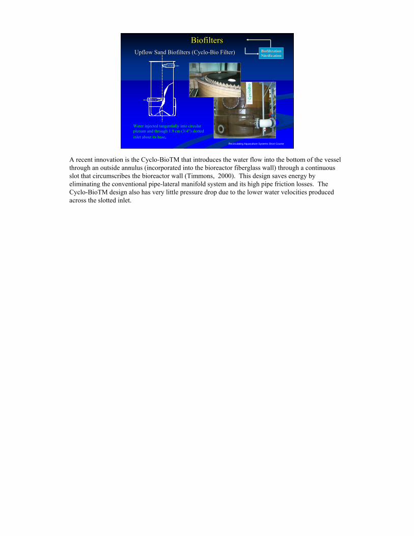
Water injected tangentially into circular plenum and through 1.9 cm (3/4”) slotted inlet about its base.
BiofiltersBiofilters
A recent innovation is the Cyclo-BioTM that introduces the water flow into the bottom of the vessel through an outside annulus (incorporated into the bioreactor fiberglass wall) through a continuous slot that circumscribes the bioreactor wall (Timmons, 2000). This design saves energy by eliminating the conventional pipe-lateral manifold system and its high pipe friction losses. The Cyclo-BioTM design also has very little pressure drop due to the lower water velocities produced across the slotted inlet.
Recirculating Aquaculture Systems Short Course
Microbead Microbead BiofilterBiofilter
BiofiltrationBiofiltrationNitrificationNitrification
BiofiltersBiofilters
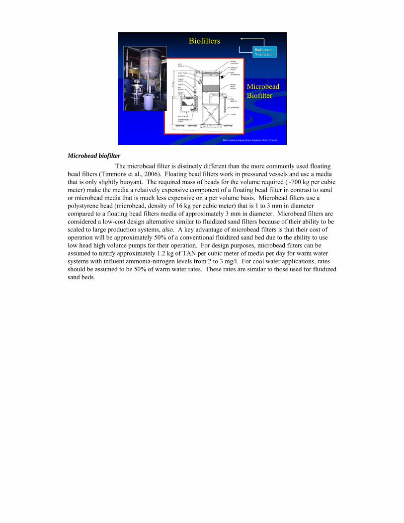
Microbead biofilterThe microbead filter is distinctly different than the more commonly used floating
bead filters (Timmons et al., 2006). Floating bead filters work in pressured vessels and use a media that is only slightly buoyant. The required mass of beads for the volume required (~700 kg per cubic meter) make the media a relatively expensive component of a floating bead filter in contrast to sand or microbead media that is much less expensive on a per volume basis. Microbead filters use a polystyrene bead (microbead, density of 16 kg per cubic meter) that is 1 to 3 mm in diameter compared to a floating bead filters media of approximately 3 mm in diameter. Microbead filters are considered a low-cost design alternative similar to fluidized sand filters because of their ability to be scaled to large production systems, also. A key advantage of microbead filters is that their cost of operation will be approximately 50% of a conventional fluidized sand bed due to the ability to use low head high volume pumps for their operation. For design purposes, microbead filters can be assumed to nitrify approximately 1.2 kg of TAN per cubic meter of media per day for warm water systems with influent ammonia-nitrogen levels from 2 to 3 mg/l. For cool water applications, rates should be assumed to be 50% of warm water rates. These rates are similar to those used for fluidized sand beds.
Recirculating Aquaculture Systems Short Course
Microbead Microbead BiofilterBiofilter
BiofiltrationBiofiltrationNitrificationNitrification
BiofiltersBiofilters
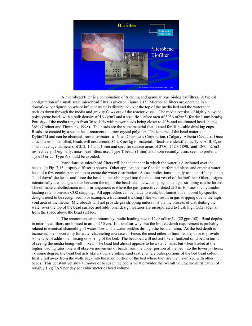
A microbead filter is a combination of trickling and granular type biological filters. A typical configuration of a small scale microbead filter is given in Figure 7.15. Microbead filters are operated in a downflow configuration where influent water is distributed over the top of the media bed and the water then trickles down through the media and gravity flows out of the reactor vessel. The media consists of highly buoyant polystyrene beads with a bulk density of 16 kg/m3 and a specific surface area of 3936 m2/m3 (for the 1 mm beads). Porosity of the media ranges from 36 to 40% with newer beads being closer to 40% and acclimated beads being 36% (Greiner and Timmons, 1998). The beads are the same material that is used for disposable drinking cups. Beads are created by a steam heat treatment of a raw crystal polymer. Trade name of the bead material is DyliteTM and can be obtained from distributors of Nova Chemicals Corporation, (Calgary, Alberta Canada). Once a local user is identified, beads will cost around $4 US per kg of material. Beads are identified as Type A, B, C, or T with average diameters of 3, 2, 1.5 and 1 mm and specific surface areas of 3780, 2520, 1890, and 1260 m2/m3 respectively. Originally, microbead filters used Type T beads (1 mm) and more recently, users seem to prefer a Type B or C. Type A should be avoided.
Variations on microbead filters will be the manner in which the water is distributed over the beads. In Fig. 7.15, a spray diffuser is shown. Other applications use flooded perforated plates and create a water head of a few centimeters on top to create the water distribution. Some applications actually use the orifice plate to "hold down" the beads and force the beads to be submerged into the retention vessel of the biofilter. Other designs intentionally create a gas space between the top of the beads and the water spray so that gas stripping can be forced. The ultimate embellishment in this arrangement is where the gas space is ventilated at 3 to 10 times the hydraulic loading rate to provide CO2 stripping. All approaches can be made to work, but limitations imposed by specific designs need to be recognized. For example, a traditional trickling filter will result in gas stripping due to the high void area of the media. Microbeads will not provide gas stripping unless it is via the process of distributing the water over the top of the bead surface and additional design features are incorporated to flush high CO2 laden air from the space above the bead surface.
The recommended minimum hydraulic loading rate is 1290 m3/ m2 d (22 gpm/ft2). Bead depths in microbead filters are limited to around 50 cm. It is unclear why, but the limited depth requirement is probably related to eventual channeling of water flow as the water trickles through the bead column. As the bed depth is increased, the opportunity for water channeling increases. Hence, the need either to limit bed depth or to provide some type of additional mixing or stirring of the bed. The bead bed will not act like a fluidized sand bed in terms of seeing the media being well mixed. The bead bed almost appears to be a static mass, but when loaded at the higher loading rates, one will observe movement of beads from the upper portion of the bed into the lower portions. To some degree, the bead bed acts like a slowly eroding sand castle, where outer portions of the bed bead column finally fall away from the walls back into the main portion of the bed where they are then re-mixed with other beads. This constant yet slow turnover of beads in the bed is what provides the overall volumetric nitrification of roughly 1 kg TAN per day per cubic meter of bead volume.
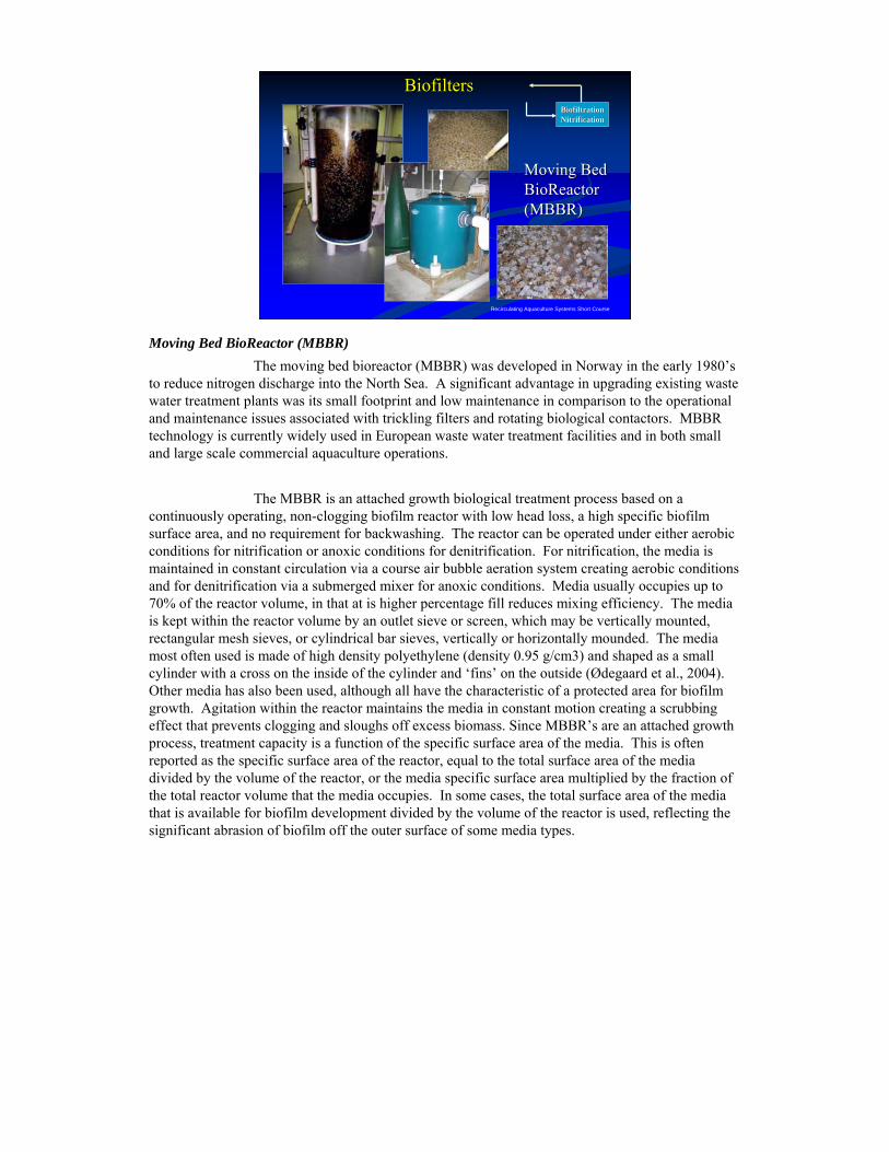
Recirculating Aquaculture Systems Short Course
Moving Bed Moving Bed BioReactor BioReactor (MBBR)(MBBR)
BiofiltrationBiofiltrationNitrificationNitrification
BiofiltersBiofilters
Moving Bed BioReactor (MBBR)The moving bed bioreactor (MBBR) was developed in Norway in the early 1980’s
to reduce nitrogen discharge into the North Sea. A significant advantage in upgrading existing waste water treatment plants was its small footprint and low maintenance in comparison to the operational and maintenance issues associated with trickling filters and rotating biological contactors. MBBR technology is currently widely used in European waste water treatment facilities and in both small and large scale commercial aquaculture operations.
The MBBR is an attached growth biological treatment process based on a continuously operating, non-clogging biofilm reactor with low head loss, a high specific biofilm surface area, and no requirement for backwashing. The reactor can be operated under either aerobic conditions for nitrification or anoxic conditions for denitrification. For nitrification, the media is maintained in constant circulation via a course air bubble aeration system creating aerobic conditions and for denitrification via a submerged mixer for anoxic conditions. Media usually occupies up to 70% of the reactor volume, in that at is higher percentage fill reduces mixing efficiency. The media is kept within the reactor volume by an outlet sieve or screen, which may be vertically mounted, rectangular mesh sieves, or cylindrical bar sieves, vertically or horizontally mounded. The media most often used is made of high density polyethylene (density 0.95 g/cm3) and shaped as a small cylinder with a cross on the inside of the cylinder and ‘fins’ on the outside (Ødegaard et al., 2004). Other media has also been used, although all have the characteristic of a protected area for biofilm growth. Agitation within the reactor maintains the media in constant motion creating a scrubbing effect that prevents clogging and sloughs off excess biomass. Since MBBR’s are an attached growth process, treatment capacity is a function of the specific surface area of the media. This is often reported as the specific surface area of the reactor, equal to the total surface area of the media divided by the volume of the reactor, or the media specific surface area multiplied by the fraction of the total reactor volume that the media occupies. In some cases, the total surface area of the media that is available for biofilm development divided by the volume of the reactor is used, reflecting the significant abrasion of biofilm off the outer surface of some media types.
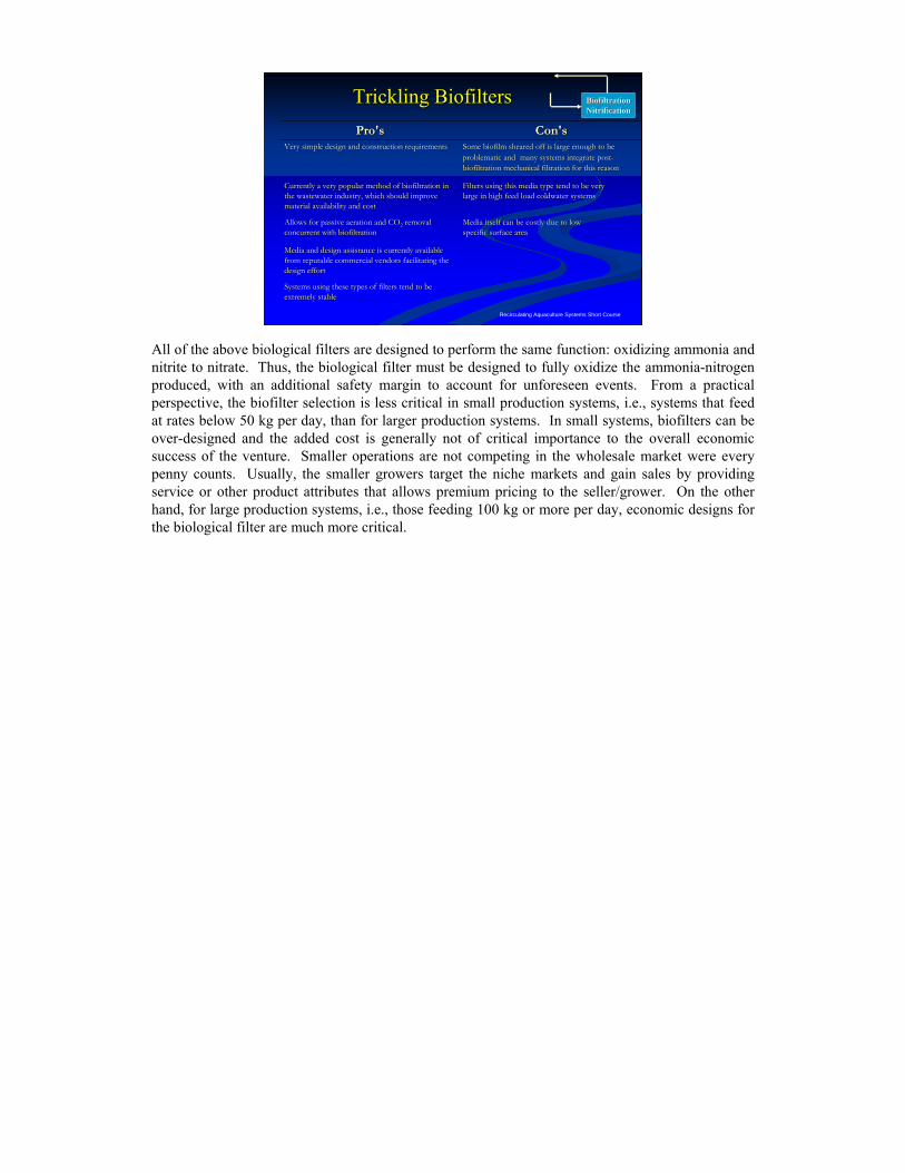
Recirculating Aquaculture Systems Short Course
Trickling BiofiltersTrickling Biofilters BiofiltrationBiofiltrationNitrificationNitrification
Systems using these types of filters tend to be Systems using these types of filters tend to be extremely stableextremely stable
Media and design assistance is currently available Media and design assistance is currently available from reputable commercial vendors facilitating the from reputable commercial vendors facilitating the design effortdesign effort
Media itself can be costly due to low Media itself can be costly due to low specific surface areaspecific surface area
Allows for passive aeration and COAllows for passive aeration and CO22 removal removal concurrent with biofiltrationconcurrent with biofiltration
Filters using this media type tend to be veryFilters using this media type tend to be verylarge in high feed load coldwater systemslarge in high feed load coldwater systems
Currently a very popular method of biofiltration in Currently a very popular method of biofiltration in the wastewater industry, which should improve the wastewater industry, which should improve material availability and costmaterial availability and cost
Some biofilm sheared off is large enough to be Some biofilm sheared off is large enough to be problematic and problematic and many systems integrate postmany systems integrate post--biofiltration mechanical filtration for this reasonbiofiltration mechanical filtration for this reason
Very simple design and construction requirementsVery simple design and construction requirements
Con'sCon'sPro'sPro's
All of the above biological filters are designed to perform the same function: oxidizing ammonia and nitrite to nitrate. Thus, the biological filter must be designed to fully oxidize the ammonia-nitrogen produced, with an additional safety margin to account for unforeseen events. From a practical perspective, the biofilter selection is less critical in small production systems, i.e., systems that feed at rates below 50 kg per day, than for larger production systems. In small systems, biofilters can be over-designed and the added cost is generally not of critical importance to the overall economic success of the venture. Smaller operations are not competing in the wholesale market were every penny counts. Usually, the smaller growers target the niche markets and gain sales by providing service or other product attributes that allows premium pricing to the seller/grower. On the other hand, for large production systems, i.e., those feeding 100 kg or more per day, economic designs for the biological filter are much more critical.
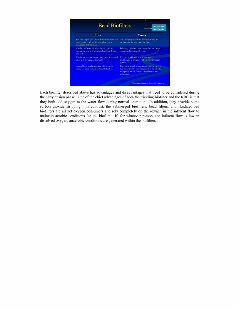
Recirculating Aquaculture Systems Short Course
Bead BiofiltersBead Biofilters BiofiltrationBiofiltrationNitrificationNitrification
Has potential to leach nutrients into system or to Has potential to leach nutrients into system or to fuel heterotrophic bacteria growth if not installed fuel heterotrophic bacteria growth if not installed with prewith pre--filtration systems or is backflushed filtration systems or is backflushed infrequentlyinfrequently
Amenable to modularization, which can be Amenable to modularization, which can be useful for development of scalable facilitiesuseful for development of scalable facilities
Variable head loss across system can be Variable head loss across system can be problematic in systems without variable speed problematic in systems without variable speed pumpspumps
Can in some cases improve fine particle removal Can in some cases improve fine particle removal rates in well designed systemsrates in well designed systems
Relatively high head loss across filter can be an Relatively high head loss across filter can be an operational cost considerationoperational cost consideration
Can be combined with other filter types in Can be combined with other filter types in interesting hybrid systems as alternative design interesting hybrid systems as alternative design methodmethod
Can be expensive due to relative low specific Can be expensive due to relative low specific surface area for large scale facilitiessurface area for large scale facilities
Well developed product available from reputable Well developed product available from reputable commercial vendors. Can simplify system commercial vendors. Can simplify system design and constructiondesign and construction
Con'sCon'sPro'sPro's
Each biofilter described above has advantages and disadvantages that need to be considered during the early design phase. One of the chief advantages of both the trickling biofilter and the RBC is that they both add oxygen to the water flow during normal operation. In addition, they provide some carbon dioxide stripping. In contrast, the submerged biofilters, bead filters, and fluidized-bed biofilters are all net oxygen consumers and rely completely on the oxygen in the influent flow to maintain aerobic conditions for the biofilm. If, for whatever reason, the influent flow is low in dissolved oxygen, anaerobic conditions are generated within the biofilters.
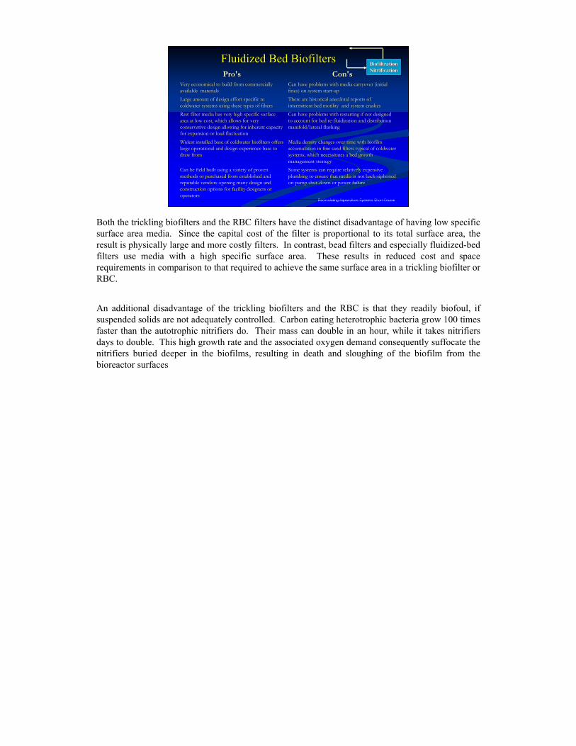
Recirculating Aquaculture Systems Short Course
Fluidized Bed BiofiltersFluidized Bed Biofilters BiofiltrationBiofiltrationNitrificationNitrification
Some systems can require relatively expensive Some systems can require relatively expensive plumbing to ensure that media is not backplumbing to ensure that media is not back--siphoned siphoned on pump shuton pump shut--down or power failuredown or power failure
Can be field built using a variety of proven Can be field built using a variety of proven methods or purchased from established and methods or purchased from established and reputable vendors opening many design and reputable vendors opening many design and construction options for facility designers or construction options for facility designers or operatorsoperators
Media density changes over time with biofilm Media density changes over time with biofilm accumulation in fine sand filters typical of coldwater accumulation in fine sand filters typical of coldwater systems, which necessitates a bed growth systems, which necessitates a bed growth management strategymanagement strategy
Widest installed base of coldwater biofilters offers Widest installed base of coldwater biofilters offers large operational and design experience base to large operational and design experience base to draw fromdraw from
Can have problems with restarting if not designed Can have problems with restarting if not designed to account for bed reto account for bed re--fluidization and distribution fluidization and distribution manifold/lateral flushingmanifold/lateral flushing
Raw filter media has very high specific surface Raw filter media has very high specific surface area at low cost, which allows for very area at low cost, which allows for very conservative design allowing for inherent capacity conservative design allowing for inherent capacity for expansion or load fluctuationfor expansion or load fluctuation
There are historical anecdotal reports of There are historical anecdotal reports of intermittent bed motility and system crashesintermittent bed motility and system crashes
Large amount of design effort specific to Large amount of design effort specific to coldwater systems using these types of filterscoldwater systems using these types of filters
Can have problems with media carryover (initial Can have problems with media carryover (initial fines) on system startfines) on system start--upup
Very economical to build from commercially Very economical to build from commercially available materialsavailable materials
Con'sCon'sPro'sPro's
Both the trickling biofilters and the RBC filters have the distinct disadvantage of having low specific surface area media. Since the capital cost of the filter is proportional to its total surface area, the result is physically large and more costly filters. In contrast, bead filters and especially fluidized-bed filters use media with a high specific surface area. These results in reduced cost and space requirements in comparison to that required to achieve the same surface area in a trickling biofilter or RBC.
An additional disadvantage of the trickling biofilters and the RBC is that they readily biofoul, if suspended solids are not adequately controlled. Carbon eating heterotrophic bacteria grow 100 times faster than the autotrophic nitrifiers do. Their mass can double in an hour, while it takes nitrifiers days to double. This high growth rate and the associated oxygen demand consequently suffocate the nitrifiers buried deeper in the biofilms, resulting in death and sloughing of the biofilm from the bioreactor surfaces