BioEntry Plus - Bosch Globalstna.resource.bosch.com/documents/Installation_Guide_enUS... · ......
36
BioEntry Plus ARD-FPBEPPR-OC | ARD-FPBEPHP-OC ARD-FPBEPIC-OC | ARD-FPBEPMF-OC en Installation manual
Transcript of BioEntry Plus - Bosch Globalstna.resource.bosch.com/documents/Installation_Guide_enUS... · ......

BioEntry PlusARD-FPBEPPR-OC | ARD-FPBEPHP-OC ARD-FPBEPIC-OC | ARD-FPBEPMF-OC
en Installation manual


BioEntry Plus Table of Contents | en 3
Bosch Access Systems GmbH Installation manual | V 1.1 | 2010.10
Table of Contents
1 Safety precautions 5
2 Basics of fingerprint recognition 6
3 How to place a finger 7
4 Product Contents 9
5 Description 12
6 Product Dimension 15
7 Cables and Connectors 16
8 Installation of Wall-mount Bracket 18
9 Connections 199.1 Power Connection 199.2 Ethernet Connection 199.3 RS485 Connections 209.4 Relay Connection 229.5 Digital Input Connection 239.6 Wiegand I/O Connection 23

4 en | Table of Contents BioEntry Plus
| V 1.1 | 2010.10 Installation manual Bosch Access Systems GmbH
10 Network Default Setting 24
11 Installation References 25
12 Electrical Specification 27
13 Troubleshooting 28
14 Device Cleaning 29
15 FCC Rules 30
16 Specifications 31
Index 32

BioEntry Plus Safety precautions | en 5
Bosch Access Systems GmbH Installation manual | V 1.1 | 2010.10
1 Safety precautionsThe list below is to keep user’s safety and prevent any loss.
– Do not install the device in a place subject to direct sun light, humidity, dust or soot.
– Do not place a magnet near the product. Magnetic objects such as magnet, CRT, TV, monitor or speaker may damage the device.
– Do not place the device next to heating equipments.– Be careful not to let liquid like water, drinks or chemicals
leak inside the device. – Clean the device often to remove dust on it.– In cleaning, do not splash water on the device but wipe it
out with smooth cloth or towel. – Do not drop the device. – Do not damage the device.– Do not disassemble, repair oralter the device.– Do not let children touch the device without supervision.– Do not use the device for any other purpose than
specified.– Contact your nearest dealer in case of a trouble or
problem.
NOTICE! Please read carefully before use.
6 en | Basics of fingerprint recognition BioEntry Plus
| V 1.1 | 2010.10 Installation manual Bosch Access Systems GmbH
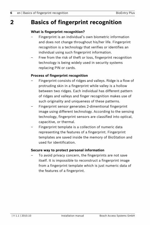
2 Basics of fingerprint recognitionWhat is fingerprint recognition?– Fingerprint is an individual’s own biometric information
and does not change throughout his/her life. Fingerprint recognition is a technology that verifies or identifies an individual using such fingerprint information.
– Free from the risk of theft or loss, fingerprint recognition technology is being widely used in security systems replacing PIN or cards.
Process of fingerprint recognition– Fingerprint consists of ridges and valleys. Ridge is a flow of
protruding skin in a fingerprint while valley is a hollow between two ridges. Each individual has different pattern of ridges and valleys and finger recognition makes use of such originality and uniqueness of these patterns.
– Fingerprint sensor generates 2-dimentional fingerprint image using different technology. According to the sensing technology, fingerprint sensors are classified into optical, capacitive, or thermal.
– Fingerprint template is a collection of numeric data representing the features of a fingerprint. Fingerprint templates are saved inside the memory of BioStation and used for identification.
Secure way to protect personal information – To avoid privacy concern, the fingerprints are not save
itself. It is impossible to reconstruct a fingerprint image from a fingerprint template which is just numeric data of the features of a fingerprint.

BioEntry Plus How to place a finger | en 7
Bosch Access Systems GmbH Installation manual | V 1.1 | 2010.10
3 How to place a fingerBosch fingerprint products show an outstanding recognition performance regardless of the user’s fingerprint skin condition or the way of fingerprint positioning. However, following tips are recommended to get more optimal fingerprint recognition performance.
Select a finger to enroll– It is recommended to use an index finger or a middle
finger. – Thumb, ring or little finger is relatively more difficult to
place in a correct position.
How to place a finger on a sensor– Place a finger such that it completely covers the sensor
area with maximum contact. – Place core part of a fingerprint to the center of a sensor.
– People tend to place upper part of a finger.– The core of a fingerprint is a center where the spiral of
ridges is dense. – Usually core of fingerprint is the opposite side of the
lower part of a nail. – Place a finger such that the bottom end of a nail is
located at the center of a sensor.– If a finger is placed as in the right picture, only a small area
of a finger is captured. So it is recommended to place a finger as shown in the left picture.
8 en | How to place a finger BioEntry Plus
| V 1.1 | 2010.10 Installation manual Bosch Access Systems GmbH
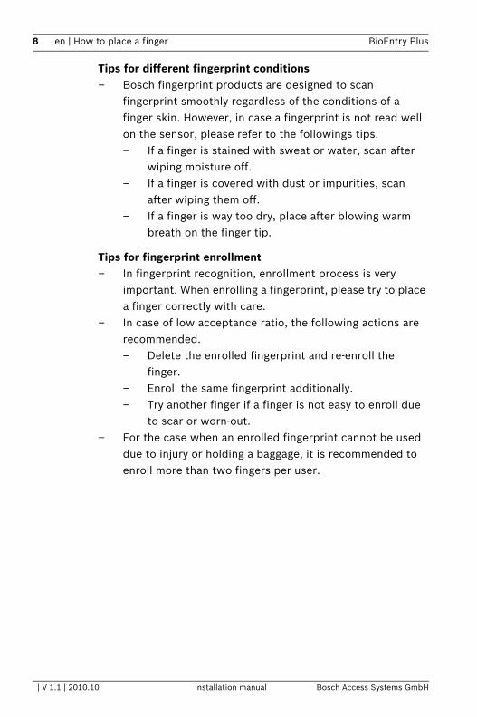
Tips for different fingerprint conditions– Bosch fingerprint products are designed to scan
fingerprint smoothly regardless of the conditions of a finger skin. However, in case a fingerprint is not read well on the sensor, please refer to the followings tips. – If a finger is stained with sweat or water, scan after
wiping moisture off.– If a finger is covered with dust or impurities, scan
after wiping them off.– If a finger is way too dry, place after blowing warm
breath on the finger tip.
Tips for fingerprint enrollment– In fingerprint recognition, enrollment process is very
important. When enrolling a fingerprint, please try to place a finger correctly with care.
– In case of low acceptance ratio, the following actions are recommended.– Delete the enrolled fingerprint and re-enroll the
finger.– Enroll the same fingerprint additionally.– Try another finger if a finger is not easy to enroll due
to scar or worn-out.– For the case when an enrolled fingerprint cannot be used
due to injury or holding a baggage, it is recommended to enroll more than two fingers per user.

BioEntry Plus Product Contents | en 9
Bosch Access Systems GmbH Installation manual | V 1.1 | 2010.10
4 Product ContentsBasic Contents
BioEntry Plus Wall-mounting metal bracket

10 en | Product Contents BioEntry Plus
| V 1.1 | 2010.10 Installation manual Bosch Access Systems GmbH
Wall mounting screws – 2 ea Star-shaped screws
Star-shaped small wrench Software CD
3 pin, 4 pin, 5 pin, 7 pin cables - each 1 ea
BioEntry Plus Product Contents | en 11
Bosch Access Systems GmbH Installation manual | V 1.1 | 2010.10
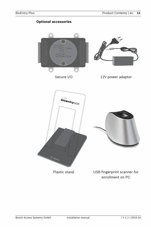
Optional accessories
Secure I/O 12V power adaptor
Plastic stand USB fingerprint scanner for enrollment on PC

12 en | Description BioEntry Plus
| V 1.1 | 2010.10 Installation manual Bosch Access Systems GmbH
5 DescriptionFront
LED Status per Color
1 RF card reading partPlace an RF card over the picture.
2 LEDDisplays current status using seven different colors.
3 Fingerprint sensing partPlace a finger on a sensor surface.
Color Mode Description
Green constant Authorization Success
Red constant Authorization Fail
Pink constant On Processing

BioEntry Plus Description | en 13
Bosch Access Systems GmbH Installation manual | V 1.1 | 2010.10
Bottom
blue/sky-blue alternating, 2 sec. normal
red/pink alternating, 2 sec. locked
blue/red alternating, 2 sec. Initialized time due to the internal battery discharge.
blue/yellow alternating, 2 sec. DHCP fail
red blinking, 2 sec. Failed. Please contact to your distributor or Bosch.
yellow blinking, 2 sec. Waiting for input.
yellow blinking, 1 sec. Receiving IP address from DHCP server.
1 Star-shaped screw hole for fixing a body to a metal bracket.
Color Mode Description
14 en | Description BioEntry Plus
| V 1.1 | 2010.10 Installation manual Bosch Access Systems GmbH
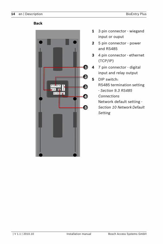
Back
1 3 pin connector - wiegand input or ouput
2 5 pin connector - power and RS485
3 4 pin connector - ethernet (TCP/IP)
4 7 pin connector - digital input and relay output
5 DIP switch:RS485 termination setting - Section 9.3 RS485 ConnectionsNetwork default setting - Section 10 Network Default Setting
BioEntry Plus Product Dimension | en 15
Bosch Access Systems GmbH Installation manual | V 1.1 | 2010.10
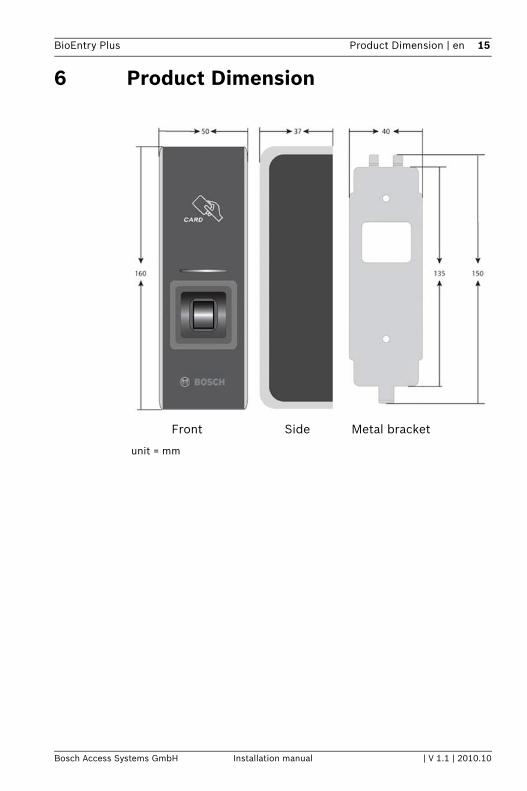
6 Product Dimension
Front Side Metal bracket
unit = mm
16 en | Cables and Connectors BioEntry Plus
| V 1.1 | 2010.10 Installation manual Bosch Access Systems GmbH
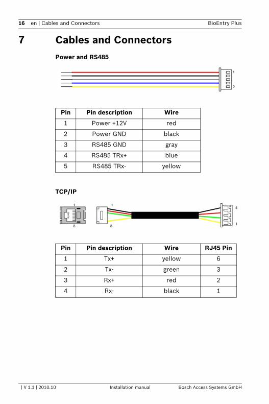
7 Cables and ConnectorsPower and RS485
TCP/IP
Pin Pin description Wire
1 Power +12V red
2 Power GND black
3 RS485 GND gray
4 RS485 TRx+ blue
5 RS485 TRx- yellow
Pin Pin description Wire RJ45 Pin
1 Tx+ yellow 6
2 Tx- green 3
3 Rx+ red 2
4 Rx- black 1

BioEntry Plus Cables and Connectors | en 17
Bosch Access Systems GmbH Installation manual | V 1.1 | 2010.10
Wiegand In/output (Switchable)
Digital Inputs and Relay output
Pin Pin description Wire
1 Wiegand Data 0 green
2 Wiegand Data 1 white
3 Wiegand GND black
Pin Pin description Wire
1 SW1 input yellow
2 SW1 GND black
3 SW2 input green
4 SW2 GND black
5 Relay normal close orange
6 Relay common blue
7 Relay normal open white
18 en | Installation of Wall-mount Bracket BioEntry Plus
| V 1.1 | 2010.10 Installation manual Bosch Access Systems GmbH
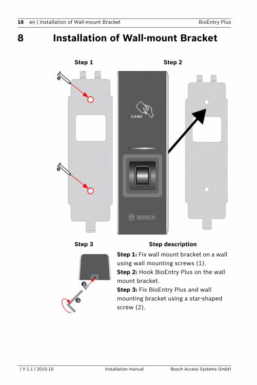
8 Installation of Wall-mount Bracket
Step 1 Step 2
Step 3 Step description
Step 1: Fix wall mount bracket on a wall using wall mounting screws (1).Step 2: Hook BioEntry Plus on the wall mount bracket.Step 3: Fix BioEntry Plus and wall mounting bracket using a star-shaped screw (2).

BioEntry Plus Connections | en 19
Bosch Access Systems GmbH Installation manual | V 1.1 | 2010.10
9 Connections
9.1 Power Connection
Recommended power supply– 12V ± 10%, at least 500mA.– Comply with standard IEC/EN 60950-1.– To share the power with other devices, use a power supply
with higher current ratings.
9.2 Ethernet ConnectionEthernet Connection via HUB

20 en | Connections BioEntry Plus
| V 1.1 | 2010.10 Installation manual Bosch Access Systems GmbH
Ethernet Connection directly with PC
To connect BioEntry Plus with a PC directly, connect both devices with a straight CAT-5 cable. As the BioEntry Plus supports auto MDI/MDIX feature, it is not necessary to use a crossover type cable.
9.3 RS485 ConnectionsRS485 Connection for Host Communication
1 = Only the devices at the both ends of the bus should be terminated. To enable termination on the RS232-485 converter, refer to the converter’s manual.
2 = Disable termination.
3 = The stubs should be as short as practical.

BioEntry Plus Connections | en 21
Bosch Access Systems GmbH Installation manual | V 1.1 | 2010.10
RS485 Connection for Secure I/O
NOTICE! – Adjust the communication speed as needed. The signal
quality vary depending on wiring conditions, and it may be necessary to lower the baudrates.
– The GND signal may be omitted if and only if the GND potential difference is less than ± 5V.
1 = Only the devices at the both ends of the bus should be terminated. To enable termination on the RS232-485 converter, refer to the converter’s manual.
2 = The stubs should be as short as practical.
NOTICE! Maximum number of devices in an RS485 loop is eight (8) including Host PC or Host device. Each device can connect Secure I/Os up to four (4)

22 en | Connections BioEntry Plus
| V 1.1 | 2010.10 Installation manual Bosch Access Systems GmbH
9.4 Relay ConnectionRelay Connection – Fail safe lock
Relay Connection – Fail secure lock
Relay Connection - Automatic door

BioEntry Plus Connections | en 23
Bosch Access Systems GmbH Installation manual | V 1.1 | 2010.10
9.5 Digital Input ConnectionDigital Input Connection - RTE, Door sensor
Digital Input Connection - Alarm, Emergency sw
9.6 Wiegand I/O ConnectionWiegand Input
Wiegand Output

24 en | Network Default Setting BioEntry Plus
| V 1.1 | 2010.10 Installation manual Bosch Access Systems GmbH
10 Network Default SettingIn case of forgetting network setting of BioEntry Plus (TCP/IP or RS-485 setting) during installation or using BioEntry Plus, user can initialize network setting (TCP/IP or RS-485 setting) by using DIP SW installed on the back panel of BioEntry Plus. Please refer to the figures in below.
How to initialize Network Setting
1. Turn off BioEntry Plus power.2. Please make DIP SW #2 ON (Please refer to figure1.)3. After turning on BioEntry Plus power, user can modify
TCP/IP or RS-485 setting what user wants. Network default settings:– TCP/IP address: 192.168.0.1– Not checked Use server– RS485: PC connection, 115200bps
4. Please modify TCP/IP or RS-485 setting and save it.5. Please make DIP SW #2 OFF (Please refer to figure 2.)6. After recycling BioEntry Plus power, please check the
modified TCP/IP or RS-485 setting.
NOTICE! Please set the IP address of a PC to 192.168.0.x (except 1) to meet IP bandwidth of the device.
BioEntry Plus Installation References | en 25
Bosch Access Systems GmbH Installation manual | V 1.1 | 2010.10
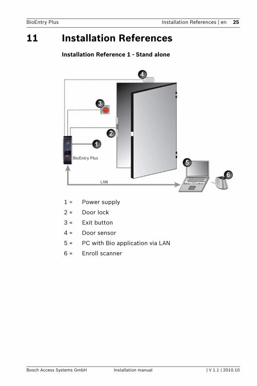
11 Installation ReferencesInstallation Reference 1 - Stand alone
1 = Power supply
2 = Door lock
3 = Exit button
4 = Door sensor
5 = PC with Bio application via LAN
6 = Enroll scanner
26 en | Installation References BioEntry Plus
| V 1.1 | 2010.10 Installation manual Bosch Access Systems GmbH
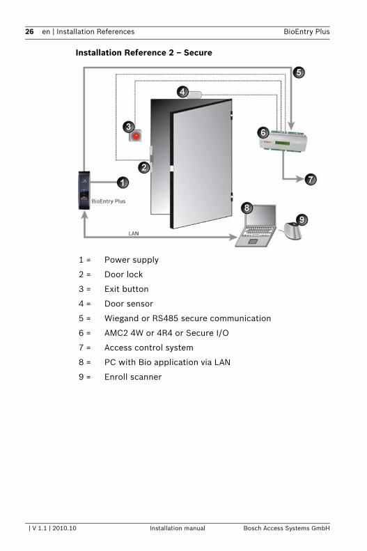
Installation Reference 2 – Secure
1 = Power supply
2 = Door lock
3 = Exit button
4 = Door sensor
5 = Wiegand or RS485 secure communication
6 = AMC2 4W or 4R4 or Secure I/O
7 = Access control system
8 = PC with Bio application via LAN
9 = Enroll scanner

BioEntry Plus Electrical Specification | en 27
Bosch Access Systems GmbH Installation manual | V 1.1 | 2010.10
12 Electrical Specification
Typ. Max. Notes
Power
Voltage (V) 12 13.2 minimum: 10.8Use regulated DC power adapter only.
Current (mA) 250
Switch Input
VIH (V) TBD
VIL (V) TBD
Pull-up resistance (Ω) 4.7k The input ports are pulled up with 4.7k resistors.
TTL/Wiegand Output
VOH (V) 5
VOL (V) 0.8
Pull-up resistance (Ω) 4.7k The output ports are open drain type, pulled up with 4.7k resistors internally.
Relay
Switching capacity (A) 10.3
30 V DC125 V AC
Switching power (resistive)
30 W37.5 VA
DCAC
Switching voltage (V) 110125
DCAC

28 en | Troubleshooting BioEntry Plus
| V 1.1 | 2010.10 Installation manual Bosch Access Systems GmbH
13 TroubleshootingFingerprint can not be read well or it takes too long.– Check whether a finger or fingerprint sensor is stained
with sweat, water, or dust– Retry after wiping off finger and fingerprint sensor with dry
towel.– If a fingerprint is way too dry, blow on the finger and retry.
Fingerprint is entered but authorization keeps failing.– Check whether the user is restricted by door zone or time
zone. – Inquire of administrator whether the enrolled fingerprint
has been deleted frin the device for some reason.
Authorized but door is not opened.– Check whether the time is set as lock time. – Check whether an antipass back mode is in use. In
antipass back mode, only who entered can exit.
Device doesn’t operate though power is connected.– Check whether a device and a bracket is well connected to
each other. If not, a tamper switch is activated and the device doesn’t work.

BioEntry Plus Device Cleaning | en 29
Bosch Access Systems GmbH Installation manual | V 1.1 | 2010.10
14 Device Cleaning– Wipe out machine surface with dry towel or cloth.– In case there is dust or impurities on the sensor of the
BioStation, wipe off the surface with dry towel.– Note that if the sensor is cleaned by detergent, benzene or
thinner, surface is damaged and fingerprint can’t be entered.

30 en | FCC Rules BioEntry Plus
| V 1.1 | 2010.10 Installation manual Bosch Access Systems GmbH
15 FCC RulesCaution– Changes or modifications not expressly approved by the
manufacturer responsible for compliance could void the user's authority to operate the equipment.
– RISK OF EXPLOSION IF BATTERY IS REPLACED BY AN INCORRECT TYPE
– DISPOSE OF USED BATTERIES ACCORDING TO THE INSTRUCTIONS
WarningThis device complies with part 15 of the FCC Rules. Operation is subject to the following two conditions: (1) This device may not cause harmful interference, and (2) this device must accept any interference received, including interference that may cause undesired operation.Information to UserThis equipment has been tested and found to comply with the limit of a Class B digital device, pursuant to Part 15 of the FCC Rules. These limits are designed to provide reasonable protection against harmful interference in a residential installation. This equipment generates, user and can radiate radio frequency energy and, if not installed and used in accordance with the instructions, may cause harmful interference to radio communications. However, there is no guaranteee that interference will not occur in a particular installation; if this equipment does cause harmful interference to radio or television reception, which can be determined by turning the equipment off and on, the user is encouraged to try to correct the interference by one or more of the following measures:1. Reorient/Relocate the receiving antenna.2. Increase the separation between equipment and receiver.3. Connect the equipment into an outlet on a circuit
difference from that to which the receiver is connected.4. Consult the dealer or an experienced radio/TV technician
for help.
BioEntry Plus Specifications | en 31
Bosch Access Systems GmbH Installation manual | V 1.1 | 2010.10
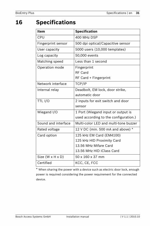
16 Specifications
* When sharing the power with a device such as electric door lock, enough
power is required considering the power requirement for the connected
device.
Item Specification
CPU 400 MHz DSP
Fingerprint sensor 500 dpi optical/Capacitive sensor
User capacity 5000 users (10,000 templates)
Log capacity 50,000 events
Matching speed Less than 1 second
Operation mode FingerprintRF CardRF Card + Fingerprint
Network interface TCP/IP
Internal relay Deadbolt, EM lock, door strike, automatic door
TTL I/O 2 inputs for exit switch and door sensor
Wiegand I/O 1 Port (Wiegand input or output is used according to the configuration.)
Sound and interface Multi-color LED and multi-tone buzzer
Rated voltage 12 V DC (min. 500 mA and above) *
Card option 125 kHz EM Card (EM4100)125 kHz HID Proximity Card13.56 MHz Mifare Card13.56 MHz HID iClass Card
Size (W x H x D) 50 x 160 x 37 mm
Certified KCC, CE, FCC

32 en | Specifications BioEntry Plus
| V 1.1 | 2010.10 Installation manual Bosch Access Systems GmbH


Bosch Access Systems GmbHCharlottenburger Allee 50D-52068 AachenGermanywww.boschsecurity.com © Bosch Access Systems GmbH, 2010