BIODEGRADATION OF POROUS CALCIUM PHOSPHATE … · Istituto Nazionale per la Ricerca sul Cancro, ......
11
136 www.ecmjournal.org European Cells and Materials Vol. 19 2010 (pages 136-146) DOI: 10.22203/eCM.v019a14 ISSN 1473-2262 Abstract Three types of ceramic scaffolds with different composition and structure [namely synthetic 100% hydroxyapatite (HA; Engipore), synthetic calcium phosphate multiphase biomaterial containing 67% silicon stabilized tricalcium phosphate (Si-TCP; Skelite™) and natural bone mineral derived scaffolds (Bio-oss®)] were seeded with mesenchymal stem cells (MSC) and ectopically implanted for 8 and 16 weeks in immunodeficient mice. X-ray synchrotron radiation microtomography was used to derive 3D structural information on the same scaffolds both before and after implantation. Meaningful images and morphometric parameters such as scaffold and bone volume fraction, mean thickness and thickness distribution of the different phases as a function of the implantation time, were obtained. The used imaging algorithms allowed a direct comparison and registration of the 3D structure before and after implantation of the same sub-volume of a given scaffold. In this way it was possible to directly monitor the tissue engineered bone growth and the complete or partial degradation of the scaffold. Further, the detailed kinetics studies on Skelite™ scaffolds implanted for different length of times from 3 days to 24 weeks, revealed in the X-ray absorption histograms two separate peaks associated to HA and TCP. It was therefore possible to observe that the progressive degradation of the Skelite™ scaffolds was mainly due to the resorption of TCP. The different saturation times in the tissue engineered bone growth and in the TCP resorption confirmed that the bone growth was not limited the scaffold regions that were resorbed but continued in the inward direction with respect to the pore surface. Keywords: Biodegradation, porous calcium phosphate scaffolds, X-ray computed microtomography, registration. *Address for correspondence: Ranieri Cancedda Istituto Nazionale per la Ricerca sul Cancro, Largo R. Benzi, 10, 16132 Genova,-Italy Telephone Number: +39-0105737398 FAX Number: +39-0105737257 E-mail: [email protected] Introduction In recent years, synthetic and natural porous ceramic materials have been widely used as scaffolds in bone tissue engineering (Anselme et al., 1999; Hench and Polak, 2002; Cancedda et al., 2003). Major requirements for such materials are biocompatibility, porosity and a biodegradation rate corresponding to the one of bone formation upon replacement of the scaffold by the new bone tissue (Langer and Vacanti, 1993). As the new bone tissue incorporates the scaffold material, the scaffold itself should be biodegradable either through cellular events or as a result of the surrounding environment (Mastrogiacomo et al. , 2007). However, the exact mechanism of the scaffold biodegradation has been only partially clarified and the results from the different studies are often contradictory. Histological observations from animal studies and human biopsies showed that calcium phosphate and hydroxyapatite (HA) based materials, such as bioactive glass and tricalcium phosphate (TCP) degrade mainly by physicochemical dissolution with osteoclasts playing only a minor role (Tadjoedin et al., 2000; Suba et al., 2006). This finding is in agreement with the results obtained by Knabe et al. (2008), who examined human biopsies and specimens from a sheep study. In these investigations, undecalcified histological sections were stained for tartrate-resistant acid phosphatase activity to reveal the possible presence of cells with osteoclastic activity close to the calcium phosphate bone substitute materials. On the contrary, other authors reported that scaffold biodegradation occurred mainly as result of an osteoclastic activity (Schepers et al., 1991; Mastrogiacomo et al., 2007). The latter mechanism of biodegradation is to be preferred (Schenk, 1991; Rumpel et al., 2006), because mimicry of the physiological bone resorption process should create optimal surfaces for colonization by osteoblasts and vascular tissue. In the literature, different opinions exist on the biodegradation of the natural bone derived mineral scaffolds, such as Bio-Oss®, but the prevalent view is that they can be resorbed (Rumpel et al., 2006). Duda and Pajak (2004), amongst others, have observed Bio- Oss® remnants in patients even several years after BIODEGRADATION OF POROUS CALCIUM PHOSPHATE SCAFFOLDS IN AN ECTOPIC BONE FORMATION MODEL STUDIED BY X-RAY COMPUTED MICROTOMOGRAPHY V.S. Komlev 1,2 , M. Mastrogiacomo 1 , R.C. Pereira 1,5 , F. Peyrin 3, , F. Rustichelli 4 , and R. Cancedda 1 * 1 Istituto Nazionale per la Ricerca sul Cancro and Dipartimento di Oncologia, Biologia e Genetica dell’Universita‘ di Genova, Genova, Italy 2 A.A. Baikov Institute of Metallurgy and Materials Science, Russian Academy of Sciences, Moscow, Russia 3 European Synchrotron Radiation Facility, 38043 Grenoble Cedex, France and CREATIS-LRMN Inserm U630; UMR CNRS 5220; INSA Lyon; Université de Lyon; 69621 Villeurbanne Cedex, France 4 Section of Physical Sciences, Department S.A.I.F.E.T., Polytechnic University of Marche, Ancona, Italy and Istituto Nazionale Biostrutture e Biosistemi (INBB) - CNISM - Matec, Ancona, Italy 5 Department of Polymer Engineering, University of Minho, Campus de Gualtar and the Institute for Biotechnology and Bioengineering, PT Government Associated Laboratory, Braga, Portugal
Transcript of BIODEGRADATION OF POROUS CALCIUM PHOSPHATE … · Istituto Nazionale per la Ricerca sul Cancro, ......

136 www.ecmjournal.org
VS Komlev et al. Biodegradation of porous calcium phosphate scaffoldsEuropean Cells and Materials Vol. 19 2010 (pages 136-146) DOI: 10.22203/eCM.v019a14 ISSN 1473-2262
Abstract
Three types of ceramic scaffolds with different compositionand structure [namely synthetic 100% hydroxyapatite (HA;Engipore), synthetic calcium phosphate multiphasebiomaterial containing 67% silicon stabilized tricalciumphosphate (Si-TCP; Skelite™) and natural bone mineralderived scaffolds (Bio-oss®)] were seeded withmesenchymal stem cells (MSC) and ectopically implantedfor 8 and 16 weeks in immunodeficient mice. X-raysynchrotron radiation microtomography was used to derive3D structural information on the same scaffolds both beforeand after implantation. Meaningful images andmorphometric parameters such as scaffold and bone volumefraction, mean thickness and thickness distribution of thedifferent phases as a function of the implantation time, wereobtained. The used imaging algorithms allowed a directcomparison and registration of the 3D structure before andafter implantation of the same sub-volume of a givenscaffold. In this way it was possible to directly monitor thetissue engineered bone growth and the complete or partialdegradation of the scaffold.
Further, the detailed kinetics studies on Skelite™scaffolds implanted for different length of times from 3days to 24 weeks, revealed in the X-ray absorptionhistograms two separate peaks associated to HA and TCP.It was therefore possible to observe that the progressivedegradation of the Skelite™ scaffolds was mainly due tothe resorption of TCP. The different saturation times in thetissue engineered bone growth and in the TCP resorptionconfirmed that the bone growth was not limited the scaffoldregions that were resorbed but continued in the inwarddirection with respect to the pore surface.
Keywords: Biodegradation, porous calcium phosphatescaffolds, X-ray computed microtomography, registration.
*Address for correspondence:Ranieri CanceddaIstituto Nazionale per la Ricerca sul Cancro,Largo R. Benzi, 10, 16132 Genova,-Italy
Telephone Number: +39-0105737398FAX Number: +39-0105737257
E-mail: [email protected]
Introduction
In recent years, synthetic and natural porous ceramicmaterials have been widely used as scaffolds in bone tissueengineering (Anselme et al., 1999; Hench and Polak,2002; Cancedda et al., 2003). Major requirements for suchmaterials are biocompatibility, porosity and abiodegradation rate corresponding to the one of boneformation upon replacement of the scaffold by the newbone tissue (Langer and Vacanti, 1993). As the new bonetissue incorporates the scaffold material, the scaffold itselfshould be biodegradable either through cellular events oras a result of the surrounding environment(Mastrogiacomo et al., 2007). However, the exactmechanism of the scaffold biodegradation has been onlypartially clarified and the results from the different studiesare often contradictory.
Histological observations from animal studies andhuman biopsies showed that calcium phosphate andhydroxyapatite (HA) based materials, such as bioactiveglass and tricalcium phosphate (TCP) degrade mainly byphysicochemical dissolution with osteoclasts playing onlya minor role (Tadjoedin et al., 2000; Suba et al., 2006).This finding is in agreement with the results obtained byKnabe et al. (2008), who examined human biopsies andspecimens from a sheep study. In these investigations,undecalcified histological sections were stained fortartrate-resistant acid phosphatase activity to reveal thepossible presence of cells with osteoclastic activity closeto the calcium phosphate bone substitute materials. Onthe contrary, other authors reported that scaffoldbiodegradation occurred mainly as result of an osteoclasticactivity (Schepers et al., 1991; Mastrogiacomo et al.,2007). The latter mechanism of biodegradation is to bepreferred (Schenk, 1991; Rumpel et al., 2006), becausemimicry of the physiological bone resorption processshould create optimal surfaces for colonization byosteoblasts and vascular tissue.
In the literature, different opinions exist on thebiodegradation of the natural bone derived mineralscaffolds, such as Bio-Oss®, but the prevalent view isthat they can be resorbed (Rumpel et al., 2006). Dudaand Pajak (2004), amongst others, have observed Bio-Oss® remnants in patients even several years after
BIODEGRADATION OF POROUS CALCIUM PHOSPHATE SCAFFOLDS IN ANECTOPIC BONE FORMATION MODEL STUDIED BY X-RAY COMPUTED
MICROTOMOGRAPHYV.S. Komlev1,2, M. Mastrogiacomo1, R.C. Pereira1,5, F. Peyrin3,, F. Rustichelli4, and
R. Cancedda1*
1 Istituto Nazionale per la Ricerca sul Cancro and Dipartimento di Oncologia, Biologia e Genetica dell’Universita‘ diGenova, Genova, Italy
2 A.A. Baikov Institute of Metallurgy and Materials Science, Russian Academy of Sciences, Moscow, Russia3 European Synchrotron Radiation Facility, 38043 Grenoble Cedex, France and CREATIS-LRMN Inserm U630;
UMR CNRS 5220; INSA Lyon; Université de Lyon; 69621 Villeurbanne Cedex, France4 Section of Physical Sciences, Department S.A.I.F.E.T., Polytechnic University of Marche, Ancona, Italy and Istituto
Nazionale Biostrutture e Biosistemi (INBB) - CNISM - Matec, Ancona, Italy5 Department of Polymer Engineering, University of Minho, Campus de Gualtar and the Institute for Biotechnology
and Bioengineering, PT Government Associated Laboratory, Braga, Portugal

137 www.ecmjournal.org
VS Komlev et al. Biodegradation of porous calcium phosphate scaffolds
implantation. Implantations performed in dog cranial bones(Merkx et al., 1997) could not demonstrate significantbiodegradation after several months, although thebiomaterial could be resorbed by osteoclast-like cells(Merkx et al., 1999). Indeed, a recent human study (Zaffeet al., 2005) reports biodegradation of these biomaterialsby osteoclasts.
The reason for such apparent discrepancies may lie inthe used models and/or the adopted techniques. In generalterms, traditional histological analyses may be scored orgraded based on degree of tissue necrosis/degeneration,fibrosis, and types and amounts of inflammatory andforeign body giant cells present. It is clear that such testsdo not fully measure biodegradation ability and do notallow the understanding of the underlying mechanisms.Fluid extracts from scaffolds may be used to determinethe presence of an acute biological reactivity and ofpossible degradation compounds (Bumgardner et al.,2004). Attempts have been performed to study resorbabilitybased on combining standard radiographic image analysisand histology (Giannoni et al., 2008). However, the resultsare clearly unsatisfactory, although consistent with theother applied techniques, and a need for improvementexists. In this context the three-dimensional (3D)nondestructive X-ray computed microtomography(microCT) may contribute to a better understanding of thebiodegradation processes and therefore, to a betterfulfillment of the tissue engineering needs for thedevelopment of the future generation biomaterials (Komlevet al., 2006; Cancedda et al., 2007). Several publicationsare dealing with studies by microCT of the biodegradationof the implanted porous scaffolds (Papadimitropoulos etal., 2007; Renghini et al., 2009). All these studies comparedin different scaffolds the percentage of the total samplevolume fracture or the thickness of the investigatedbiomaterials either before (control) or after implantation.At most, different sub-volumes of the same scaffolds beforeand after implantation were analyzed. Therefore, scaffolddegradation rate and mechanism were not exactlymonitored by these approaches.
In fact, microCT images of the same scaffold volumeacquired at different times (before and after implantation)should be combined to more satisfactorily study thescaffold biodegradation. However, structures are likely tohave changed their positions between the acquisitions dueto a number of reasons, and combining the images couldbe a very difficult experimental task. Indeed, combiningthese types of images requires their geometric warping sothat corresponding image structures correctly align – imageregistration. Such techniques have for instance beenapplied to the evaluation of bone loss in ovariectomizedanimal models (Waarsing et al., 2006; Klinck et al., 2008).At the present, there are a number of different kinds ofregistration techniques (Brown 1992; van den Elsen et al.,1993; Modersitzki, 2004; Schmitt et al., 2007) for differentregistration problems, in particular for the alignment ofimages of serial sections. This includes e.g., rigid, affineand elastic registration. Rigid and affine transformationsare easy to be unequivocally formulated in simplemathematical terms and need only very few parameters tobe adjusted for registration, namely: translations, rotations,
scaling factors, and skewing factors. However, significantdeviations may remain after rigid/affine registrations. Tocompensate for those, elastic registration needs to beapplied. Contrary to its rigid/affine counterparts, elasticregistration has not yet become a standard technique thatis used on a routine basis, the reason being that elasticregistration is much more difficult to achieve and, as ofyet, no generally accepted solution is available (Hamischet al., 2006). These methods will help with the registrationof highly disparate modalities that provide insufficientimage structures. On the other hand, none of them wereapplied to investigate biodegradation of the scaffolds.
In this work, to investigate scaffold degradation, a well-established model of ectopic bone formation was adoptedin which bone marrow-derived mesenchymal stem cells(MSC) were loaded onto different porous scaffolds andsubcutaneously implanted in immunodeficient mice.Scaffolds implanted in the mice for different lengths oftime were analyzed by microCT using registration ofseveral series of images.
Materials and Methods
Porous ceramic scaffolds and tissue engineeringconstructsMarrow aspirates were obtained from the iliac crest ofsheep as part of a protocol approved by the competentethics authority. Detailed protocol for bone marrow-derived mesenchymal stem cells (MSC) expansion in vitroand histological protocols have been described elsewhere(Muraglia et al., 1998). Briefly, the cell-nucleated fractionof 20 mL bone marrow aspirate was suspended in Coon’smodified Ham’s F12 medium supplemented with 10% fetalcalf serum, human recombinant fibroblast growth factor 2(1 ng/mL), and antibiotics, and plated at a density of 1×10⁶
cells/cm2. Medium was changed twice a week. Whenculture dishes were nearly confluent (passage 0), MSCwere detached with trypsin-EDTA and 5×10⁵ cells werereplated in 100 mm dishes (passage 1). At the nextsubconfluence, MSC were detached and used for implants.
Three types of bioceramic scaffolds were considered,namely synthetic 100 % hydroxyapatite (HA; Engipore),synthetic calcium phosphate multiphase biomaterialcontaining 67% silicon stabilized tricalcium phosphate (Si-TCP; SkeliteTM) and natural bone mineral derived scaffold(Bio-Oss®). All scaffolds were small cubes with adimension of about 4×4×4mm. Bioceramic/MSCcomposites were implanted subcutaneously on the backof the mice (up to four implants for each animal). Micewere sacrificed at different lengths of time afterimplantation, and the harvested samples were fixed inparaformaldehyde (PFA 4% in phosphate buffered saline,PBS) for 2 h at 4°C.
Image acquisition: synchrotron radiation microCTMicroCT experiments were performed using synchrotronradiation at the ID19 beam line of the EuropeanSynchrotron Radiation Facility (ESRF) in Grenoble,France. The acquisition setup is based on three-dimensional(3D) parallel tomography previously described (Salome

138 www.ecmjournal.org
VS Komlev et al. Biodegradation of porous calcium phosphate scaffolds
et al., 1999). Briefly, the transmitted intensity was recordedby a two-dimensional (2D) detector, which consists of aGadox scintillator (an X-ray-to-visible light converter),light optics for magnification of the image, and a FReLoNCCD camera developed at the ESRF. The camera has 14-bit dynamic range and a 2048×2048 pixel chip. In ourexperiments, the pixel size was fixed at 4.91 μm, thusyielding a field view of 6 mm. The sample-to-detectordistance was fixed at 15 mm and a 27 keV beam energywas found to provide suitable contrast as reported in(Komlev et al., 2006). The exposure time was 3 s perprojection. For each sample, 1100 radiographic images (orprojections) with 2048×2048 pixels were acquired atdifferent angles of view, ranging from 0 to 180°.
Image reconstruction for microCTAfter tomographic acquisitions, 3D images werereconstructed from the series of 2D projections using a3D filtered back projection algorithm implemented atESRF (Salome et al., 1999). A volume of about 8003 voxelswas reconstructed, yielding a voxel with a 4.91 μm size inthe three directions of space.
3D visualization and parameters quantificationDirect volume rendering (DVR) methods were selected tomap elements directly into screen space without usinggeometric primitives as an intermediate representation. Tothis end, the commercial software VG Studio MAX 1.2.1(Volume Graphics GmbH, Heidelberg, Germany) was usedto produce 3D images, which efficiently implementedvarious DVR methods, especially with large volumedatasets.
Volume segmentationsAn automated multi-threshold segmentation method basedon (Otsu et al., 1979) was used to highlight and separatethe different phases (scaffold, bone) from background.More precisely, after separation of the different phases bya multi-thresholding procedure of post implanted samples,each of the histograms was partitioned in equal zonesaccording to (Papadimitropoulos et al., 2007).
Image analysis tools derived from mathematicalmorphology are often used to process images (Matheron,1975; Serra, 1982). The basic morphological operationsare erosion and dilation. Dilation, in general, causes objectsto dilate or grow in size; erosion causes objects to shrink.The amount and the way that they grow or shrink dependupon the choice of the structured element. The openingoperation is somewhat like erosion in that it tends to removesome of the foreground (bright) pixels from the edges ofregions of foreground pixels. On the other hand, “closing”is similar in some ways to dilation but it is less destructiveof the original boundary shape (Iyer and Sinha, 2006).Therefore, the mathematical morphology operator“closing” was applied to enlarge the boundaries offoreground regions, shrink background holes and isolatedpoints.
Extraction of quantitative parametersThe 3D data volumes produced by the image reconstructionprocess were used in order to quantify the parameters,
which characterize the structures of the scaffold and ofthe new bone. Once the different phases were segmented,volumes of the phases itself (bone volume and scaffoldvolume) were easily calculated counting the voxels in thespecified segmented data range. Morphometric parameters,such as new bone and scaffold thicknesses, were evaluatedaccording to (Dougherty and Kunzelmann, 2007), wherethe mean thickness and its distribution were calculated ina direct way and independently of an assumed structuralmodel. Briefly, the computation of the thickness value wasdefined as the average of the local thickness at each voxelrepresenting a given phase (new bone and scaffold). Thevolume-based local thickness for a point in a phase wasdefined as the maximal diameter of a sphere, whichsatisfies simultaneously the conditions: (a) the sphereencloses the point and (b) the sphere is entirely boundedwithin the phase.
Volume registrationIn the first approach we applied well-known affine linearregistration that is based on gray level intensities. Volumeregistration was used in Java as a plugin for free opensoftware ImageJ (http://rsbweb.nih.gov). It can beperformed by automatic 3D registration either on the wholevolume or on the selected subvolume. Volume registrationusing the whole volume can be too lengthy to be practicalfor moderately sized images. Therefore, only the selected3D subvolumes after segmentations (see Volumesegmentation) were registered. The value of the similarityfunction during optimization was applied too. Similarityfunctions include correlation coefficient, sum of absolutedifferences, and mutual information. Transformationsinclude various types of affine (non-warping) operations.The optimization algorithms include Powell’s algorithm,a parabolic fit to random points, simulated annealing, orno operation (useful for plotting). Interpolation methodsinclude nearest neighbor, tri-linear and a random jitter.Similarity functions can be summarized as follow: thecorrelation coefficient is defined as E{(f-mf)*(g-mg)}/(E{(f-mf)
2}*E{(g-mg)2})1/2, where f and g are the pixel
values of two images (F and G), E{} is the average overthe pixels in the image, and mf and mg are the respectivemean values. The correlation coefficient is just a crosscorrelation normalized for the power in the images. Thesum of absolute differences is defined as 1-sum{|(f-mf)-(g-mg)|}/sum{|f-mf|+|g-mg|}, where sum{} is the sum overthe pixels in the image. Both the correlation coefficientand the sum of absolute differences assume that the twoimages are on the same scale. White objects in Fcorrespond to white objects in G, and black objects in Fcorrespond to black objects in G. These two similarityfunctions are most appropriate for aligning images fromthe same modality, e.g. microCT. More information canbe found at http://rsbweb.nih.gov.
However, after affine linear registration, images areaffected by local nonlinear deformations that need to bereduced by the nonlinear approach elastic registration(Schmitt et al., 2007). Therefore, a local nonlineartechnique like elastic registration is an inevitable procedurefor a consequent final alignment of microCT images. Tothis purpose, an ImageJ plugin that allows the simultaneous

139 www.ecmjournal.org
VS Komlev et al. Biodegradation of porous calcium phosphate scaffolds
registration of two images based on elastic deformationsrepresented by B-splines was used (Sánchez Sorzano etal., 2005). B-splines are piecewise-polynomial bases witha low computational cost, which makes them veryattractive. Because their approximation properties areoptimal in a mathematically well-defined sense, they areextremely useful to model many functions; in particular,the deformation field can be viewed as a set of severalfunctions (one per coordinate) which in turn are modeledby a linear sum of weighted and shifted B-splines. The setof weights, which are called the B-spline coefficients, fullycharacterize the transformation (Sánchez Sorzano et al.,2005).
Finally, synchronization should be used.Synchronization may be interactive or partially or fullyautomatic with help of a fusion algorithm that is describedelsewhere (Stokking et al., 2003). We adopted the fullfusion automatic algorithm. The exact synchronization ofdata sets provides capacity for image fusion withsuperimposition of both sets of imaging data in one imagedata set for further treatment.
Results
To investigate scaffold biodegradation occurring in vivo,microCT acquisitions were performed on the samescaffolds prior and after cell seeding and implantation thusenabling in situ comparative studies. Small cubes of threedifferent scaffolds (Engipore (hydroxyapatite), SkeliteTM
(silicon-stabilized tricalcium phosphate) and Bio-Oss®(natural bone mineral)) were imaged (Fig. 1) before cellseeding and implantation in immunodeficient mice for 8and 16 weeks, respectively. Significant differences existedin the internal microarchitecture of the three scaffolds.Histomorphometric data for the scaffolds beforeimplantation are reported in Table 1.
When microCT data of the scaffolds obtained bothbefore and after implantation were considered, we firstcompared the thickness distributions of the scaffold walls(Fig. 2 panels A-C). Examples of a central virtual slicethrough the 3D structure of each sample showing the localwall thickness map before and after implantation, areshown in Fig. 2 (panels A1-C2). From these distributionsa significant degradation in the implanted scaffold couldbe observed only in SkeliteTM. In Engipore and Bio-Oss®no and a little decrease, respectively, of the scaffold wallthickness were detected. To illustrate the quality of thedata an example of data treatment for non- (Engipore) andresorbable (SkeliteTM) scaffolds is presented in Fig. 3. Ourobtained results are in agreement with those reported in(Papadimitropoulos et al., 2007; Peyrin et al., 2007;Dougherty and Kunzelmann, 2007).
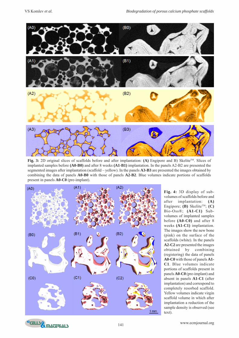
Volume registration was used to register images of thesame scaffolds before and after implantation as describedin the Materials and Methods section. The 3D displays ofsubvolumes of all three scaffolds before implantation areshown in Fig. 4 (panels A0-C0). In order to have a pictorialview and a better basis for the interpretation of theregistered images, in Fig. 4 (panels A1-C1) we also present
PoreD (microns) PoreV (%) S.Th (microns)
Engipore 430±202 79±5 101±42
SkeliteTM 655±354 75±5 215±175
Bio-Oss® 455±155 81±3 141±47
Table 1. Histomorphometric data for scaffolds before implant.
S.Th = scaffold mean thickness; PoreV = total volume of the pores; PoreD = pore diameter.
Fig. 1: 3D display of different scaffolds before implantation: (A) Engipore (hydroxyapatite) produced by FinCeramica,Faenza, Italy; (B) SkeliteTM (silicon-stabilized tricalcium phosphate) produced by Millenium Biologics Kingston,Ontario, Canada; (C) Bio-Oss® (natural bone mineral) produced by Geistlich Pharma AG, Wolhusen, Switzerland.

140 www.ecmjournal.org
VS Komlev et al. Biodegradation of porous calcium phosphate scaffolds
images of the bone tissue-engineered constructs of the samesub-volumes at 8 weeks after implantation in mice.Scaffold material (white) and the new bone (pink) areclearly visible. The 3D displays of the registered pre- andpost implanted images are shown in panels A2-C2: bluevolumes indicate portions of scaffolds present in the pre-implantation sample and to void volumes after implantationand correspond to completely resorbed scaffolds. Yellowvolumes indicate original scaffold volumes in which afterimplantation a reduction of the sample density wasobserved and could correspond to partially resorbedscaffold, or to deposited bone with a higher density (bonewith a particular high mineral content), or a combinationof the two (bone deposition in a partially resorbed scaffold).Also this type of analysis confirmed that a significantscaffold biodegradation after 8 weeks implantationoccurred only in the SkeliteTM sample, while a minimalbiodegradation was observed in the Bio-Oss® and nonein the Engipore samples. Based on these findings, thescaffold degradation in the tissue engineered implantedconstructs was investigated after 16 weeks implantationonly for the SkeliteTM.
3D displays of registered images of pre- and postimplantation SkeliteTM samples implanted for 8 (A) and16 (B) weeks are presented in Fig. 5 (panels A-B),
respectively. As in the registered images of Fig. 4 (panelB2) blue and yellow correspond to totally and partiallyresorbed scaffold, respectively. The volume percentagedistribution of the different phases is presented in panelsA1 and B1. An increase in the percentage of the resorbedscaffold was observed with the increased implantationtime.
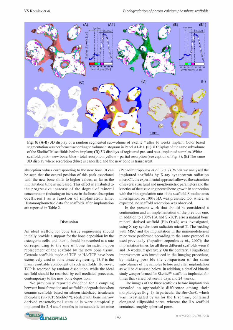
To better investigate the transition zone betweenSkeliteTM scaffold and bone where an overlap could existbetween newly deposited bone and partially resorbedscaffold, as well as to depict spatial correlations betweenthe different phases, different color hues were applied tothe volume histograms (Papadimitropoulos et al., 2007).In Fig.6, after separation of the different phases by a multi-thresholding procedure (see Materials and Methods), eachof the histograms was partitioned in equal zones (Fig. 6,panel A1-B1). A pink color progressively changing to whitewas used to identify the scaffold whereas a red color turningto cyan was applied to the new bone phase. Additionally,the green-cyan colors were chosen to identify the transitionphase. In Fig. 6 (panel A-B) two different 3D-reconstructions of the same volume and their partitionedhistograms for the 16 weeks implant are shown. Thesegregation of the pink hues close to the bone depositionzones, which characterizes the scaffold phase observed in
Fig. 2: Histograms of the distribution of wall thickness before and after scaffold implantation: (A) Engipore(hydroxyapatite); (B) SkeliteTM (silicon-stabilized tricalcium phosphate); (C) Bio-Oss® (natural bone mineral).NbTh = New Bone Thickness. (A1-C2) Examples of central slices through the samples within the 3D local wallthickness map before (A1-C1) and after implantation (A2-C2). The thickness in each point is coded according to thecolor map included in panels A1, B1, C1.
141 www.ecmjournal.org
VS Komlev et al. Biodegradation of porous calcium phosphate scaffolds
Fig. 3: 2D original slices of scaffolds before and after implantation: (A) Engipore and B) SkeliteTM. Slices ofimplanted samples before (A0-B0) and after 8 weeks (A1-B1) implantation. In the panels A2-B2 are presented thesegmented images after implantation (scaffold – yellow). In the panels A3-B3 are presented the images obtained bycombining the data of panels A0-B0 with those of panels A2-B2. Blue volumes indicate portions of scaffoldspresent in panels A0-C0 (pre-implant).
Fig. 4: 3D display of sub-volumes of scaffolds before andafter implantation: (A)Engipore; (B) SkeliteTM; (C)Bio-Oss®; (A1-C1) Sub-volumes of implanted samplesbefore (A0-C0) and after 8weeks (A1-C1) implantation.The images show the new bone(pink) on the surface of thescaffolds (white). In the panelsA2-C2 are presented the imagesobtained by combining(registering) the data of panelsA0-C0 with those of panels A1-C1. Blue volumes indicateportions of scaffolds present inpanels A0-C0 (pre-implant) andabsent in panels A1-C1 (afterimplantation) and correspond tocompletely resorbed scaffold.Yellow volumes indicate virginscaffold volume in which afterimplantation a reduction of thesample density is observed (seetext).

142 www.ecmjournal.org
VS Komlev et al. Biodegradation of porous calcium phosphate scaffolds
the post-implant scaffolds (panel A-B), but not in the pre-implant scaffold (not shown), suggests that the new bonedeposition was associated with the occurrence of somescaffold alterations.
For the same sample sub-volume a registration wasperformed of the scaffolds before and after implantation(panels C-F). Panel F is a replica of panel D in which theblue volumes (completely resorbed scaffold) have beencanceled and the red volume (bone) made transparent tobetter visualize the volumes underneath. Arrowheadsindicate some of the areas of resorbed scaffold where newbone has been deposited (Compare panel F and panel A).
To complete the study, composition and volumes ofthe SkeliteTM scaffolds and new bone volumes werequantified in samples implanted for different times, from3 days to 24 weeks. Volume histograms of implantedscaffolds are shown in Fig. 6A. In the pre-implantedSkeliteTM scaffolds 2 peaks were observed for relativelyhigh values of the coefficient, corresponding to the scaffoldmaterial two components – tricalcium phosphate (TCP)and hydroxyapatite (HA). The TCP volume decreased withincreasing time of implantation. The HA volume wasalmost constant. In the implanted samples for more than 2weeks an additional peak was observed at lower X-ray
Fig. 5: Display based on a combination of the 3D structure of pre- and post implanted SkeliteTM samples for 8 (A) and16 (B) weeks, respectively (white – scaffold; pink – new bone; blue – total resorption; yellow – partial resorption (seecaption of Fig. 3). (A1-B1) volume percentage distribution of the different phases.
NB.Th (microns) NB.V (%) S.Th
(microns)
Engipore 34±5 5.2±0.5 99±41
SkeliteTM 47±5 7.1±0.5 134±123
Bio-Oss® 53±5 8.4±0.5 131±45
Table 2. Histomorphometric data for MSC seeded scaffolds after 8 week implantation
NB.Th = newly formed bone mean thickness; NB.V = newly formedbone volume; S.Th = scaffold mean thickness after implantation.
143 www.ecmjournal.org
VS Komlev et al. Biodegradation of porous calcium phosphate scaffolds
absorption values corresponding to the new bone. It canbe seen that the central position of this peak associatedwith the new bone shifts to higher values, as far as theimplantation time is increased. This effect is attributed tothe progressive increase of the degree of mineralconcentration (inducing an increase in the linear absorptioncoefficient) as a function of implantation time.Histomorphometric data for scaffolds after implantationare reported in Table 2.
Discussion
An ideal scaffold for bone tissue engineering shouldinitially provide a support for the bone deposition by theosteogenic cells, and then it should be resorbed at a ratecorresponding to the one of bone formation uponreplacement of the scaffold by the new bone tissue.Ceramic scaffolds made of TCP or HA/TCP have beenextensively used in bone tissue engineering. TCP is themain resorbable component of such scaffolds. However,TCP is resorbed by random dissolution, while the idealscaffold should be resorbed by cell-mediated processes,contemporary to the new bone deposition.
We previously reported evidence for a couplingbetween bone formation and scaffold biodegradation whenceramic scaffolds based on silicon stabilized tricalciumphosphate (Si-TCP; Skelite™), seeded with bone marrowderived mesenchymal stem cells were ectopicallyimplanted for 2, 4 and 6 months in immunodeficient mice
Fig. 6: (A-B) 3D display of a random segmented sub-volume of SkeliteTM after 16 weeks implant. Color basedsegmentation was performed according to volume histogram in Panel A1-B1; (C) 3D display of the same subvolumeof the SkeliteTM scaffolds before implant; (D) 3D displays of registered pre- and post-implanted samples. White –scaffold, pink – new bone, blue – total resorption, yellow – partial resorption (see caption of Fig. 3); (E) The same3D display where resorbtion (blue) is cancelled and the new bone is transparent.
(Papadimitropoulos et al., 2007). When we analysed theimplanted scaffolds by X-ray synchrotron radiationmicroCT, the experimental approach allowed the extractionof several structural and morphometric parameters and thekinetics of the tissue engineered bone growth in connectionwith the biodegradation rate of the scaffold. Simultaneousinvestigation on 100% HA was presented too, where, asexpected, no scaffold resorption was observed.
In the present work that should be considered acontinuation and an implementation of the previous one,in addition to 100% HA and Si-TCP, also a natural bonemineral derived scaffold (Bio-Oss®) was investigated,using X-ray synchrotron radiation microCT. The seedingwith MSC and the implantation in the immunodeficientmice were performed according to the same protocol asused previously (Papadimitropoulos et al., 2007); theimplantation times for all three different scaffolds were 8and 16 weeks, respectively. On the contrary, a significantimprovement was introduced in the imaging procedure,by making possible the comparison of the samesubvolumes of the samples before and after implantationas will be discussed below. In addition, a detailed kineticstudy was performed for Skelite™ scaffolds implanted fortimes that varied between 3 days and 24 weeks.
The images of the three scaffolds before implantationrevealed an appreciable difference among theirmorphologies (Fig. 1). In particular the Bio-Oss®, whichwas investigated by us for the first time, containedelongated ellipsoidal pores, whereas the HA scaffoldcontained roughly spherical pores.

144 www.ecmjournal.org
VS Komlev et al. Biodegradation of porous calcium phosphate scaffolds
The histograms of the distribution of the thickness ofthe scaffold wall of Fig. 2 (A) and 2(B), confirmed theresults previously obtained in (Papadimitropoulos et al.,2007), namely biodegradation for the Si-TCP scaffold andlack of it for the HA scaffold. The newly investigated Bio-Oss® showed a very little decrease of the scaffold wallthickness; the decrease was at the limit of detectability,and needs to be confirmed by additional experiments.Panels A1-C1, obtained by an imaging technique, not usedin (Papadimitropoulos et al., 2007), give an instantaneouspictorial view of the variation in scaffold wall thicknessand confirm in a rather impressive way the uniqueness ofthe biodegradation process in Skelite™.
Probably the strongest driver for combined imaging inbone tissue engineering is its capability to provide anappreciable contribution to a better understanding of thescaffold biodegradation phenomenon. The obtained resultsdemonstrated the benefits of the imaging treatment usedin the present study. However, a registration algorithm thathas been configured for a specific target application suchas a scaffold biodegradation study must be validated inview of the application requirements. Validation requiressome basic truth from which the quality of a registrationresult can be inferred (Hamisch et al., 2006). Therefore,some phantom images are needed which can provide abasic truth for a technical validation to estimate consistency
and accuracy of a registration procedures. In our case thestudy was performed on Engipore scaffold in order toobtain a validation of the registration used. We showedthat Engipore scaffold before and after implantation weresuperimposed with a high accuracy. This result correlateswith the common knowledge based on literature data thatHA is a non-biodegradable material. Moreover, theobserved and quantified general biodegradation behaviorof SkeliteTM and Bio-Oss® according to the present workwere in agreement with previously reported data (Komlevet al., 2006; Cancedda et al., 2007; Merkx et al., 1997;Merkx et al., 1999; Rumpel et al., 2006).
On this basis, to obtain information on the 3D structuralchanges of the scaffolds occurring during the implantation,the same image treatment that allows a direct comparisonof the 3D structure (before and after implantation) of thesame sub-volume of a given scaffold, was applied to allthree scaffolds. The data reported in Figures 4-6 show thegood performance of the adopted procedure, demonstratingthe visualization at the same time of both the tissue-engineered bone growth and the complete or partialbiodegradation of the scaffold.
The analysis proposed in the present paper is a majorimprovement as compared to the imaging procedureadopted in our previous work (Papadimitropoulos et al.,2007), where only a comparison between different sub-
Fig. 7: Volume histograms of SkeliteTM scaffolds implanted from 3 days to 24 weeks (NB – new bone, TCP –tricalcium phosphate, HA – hydroxyapatite). (A) New bone deposition kinetics; (B) Percentage of bone volume/total volume; (C) TCP/HA mean ratio as a function of the implantation time.

145 www.ecmjournal.org
VS Komlev et al. Biodegradation of porous calcium phosphate scaffolds
volumes of the implants before and after implantation wasmade.
Finally, a high content of innovation is associated tothe detailed kinetics studies on the Skelite™ scaffoldsimplanted for different times, not only due to the largenumber of the implantation times investigated, but also tothe recording in the X-ray absorption histograms ofseparate peaks associated to HA and TCP in the samescaffold (Fig. 7). It is therefore possible to observe thatthe progressive biodegradation of Skelite™ scaffold iseventually due to the TCP component.
It should be noted that when we investigated by micro-diffraction studies the interfaces between the newly formedbone and the Skelite™ scaffold, the local structural studyat the interface indicated that scaffold biodegradation wasmainly due to TCP depletion (Papadimitropoulos et al.,2007).
Moreover, saturation in the TCP resorption occurredat an implantation time of about 8 weeks, whereassaturation in the tissue engineered bone occurred at animplantation time of about 24 weeks. This could indicatethat the bone growth did not occur only in the scaffoldvolume that was resorbed, but also in the inward directionwith respect to the pore surface. This finding is inagreement with the results presented in Fig. 5 of reference(Mastrogiacomo et al., 2007), and in Fig. 4 of reference(Papadimitropoulos et al., 2007).
Conclusion
The obtained results in addition to confirming the well-known non-biodegradability of HA demonstrated that theobserved and quantified general biodegradation behaviorof SkeliteTM and Bio-Oss® is in agreement with thatreported in (Komlev et al., 2006; Cancedda et al., 2007;Merkx et al., 1997; Merkx et al., 1999; Rumpel et al.,2006).
Nevertheless, the promising and effective 3D microCTregistration procedure employed in the present work,together with the adoption of a large number ofimplantation times, introduces an appreciable increase inthe existing information with regard to biodegradation ofbone mimetic scaffolds and of Si-TCP based scaffolds inparticular. The new approach allows a deeper insight inthe investigated biological phenomena, and can beextrapolated further in bone tissue engineering researchpossibly by combining the data with the 3D data onangiogenesis obtained by the use of holotomographictechnique (Komlev et al., 2009).
Acknowledgements
Supported by funds from the Italian (ASI) and theEuropean (ESA-ERISTO) Space Agencies and from FP7EU (Angioscaff) funds.
References
Anselme K, Noël B, Flautre D, Blary M-C, DelecourtC, Descamps M, Hardouin P (1999) Association of porous
hydroxyapatite and bone marrow cells for boneregeneration. Bone 25: 51S-54S.
Brown L (1992) A survey of image registrationtechniques. ACM Comp Surv 24: 325-376.
Bumgardner JD, Vasquez-Lee M, Fulzele KS, SmithDH, Branch KD, Christian SI, Williams DH (2004)Biocompatibility Testing. In: Encyclopedia of Biomaterialsand Biomedical Engineering, Marcel Dekker, New York,pp 79-88.
Cancedda R, Cedola A, Giuliani A, Komlev V,Lagomarsino S, Mastrogiacomo M, Peyrin F, RustichelliF (2007) Bulk and interface investigations of scaffolds andtissue-engineered bones by X-ray microtomography andX-ray microdiffraction. Biomaterials 28: 2505-2524.
Cancedda R, Dozin B, Giannoni P, Quarto R (2003)Tissue engineering and cell therapy of cartilage and bone.Matrix Biol 22: 81-91.
Dougherty RP, Kunzelmann K-H (2007) Computinglocal thickness of 3D structures. Microsc Microanal13(Suppl 2): 1678CD.
Duda M, Pajak J (2004) The issue of bioresorption ofthe Bio-Oss xenogeneic bone substitute in bone defects.Ann Univ Mariae Curie Sklodowska [Med] 59: 269-277.
Giannoni P, Mastrogiacomo M, Alini M, Pearce SG,Corsi A, Santolini F, Muraglia A, Bianco P, Cancedda R(2008) Regeneration of large bone defects in sheep usingbone marrow stromal cells. J Tissue Eng Regen Med 2:253-262.
Hamisch Y, Egger M, Hines H, Fiedler K, Carlsen I(2006) Clinical hybrid imaging: image co-registration andhardware combination for PET/CT and SPECT/CT. In:Advances in Healthcare Technology (Spekowius G,Wendler T, eds), Springer, Dordrecht, The Netherlands,pp 117-138.
Hench LL, Polak JM (2002) Third-generationbiomedical materials. Science 295: 1014-1017.
Iyer S, Sinha SK (2006) Segmentation of pipe imagesfor crack detection in buried sewers. Computer-Aided Civiland Infrastructure Engineering 21: 395-410.
Klinck J, Boyd SK (2008) The magnitude and rate ofbone loss in ovariectomized mice differs among inbredstrains as determined by longitudinal in vivo micro-computed tomography. Calcif Tissue Int 83:70-79.
Knabe C, Koch Ch, Rack A, Stiller M (2008) Effect ofβ-tricalcium phosphate particles with varying porosity onosteogenesis after sinus floor augmentation in humans.Biomaterials 29: 2249-2258.
Komlev VS, Mastrogiacomo M, Peyrin F, CanceddaR, Rustichelli F (2009) X-ray synchrotron radiationpseudo-holotomography as a new imaging technique toinvestigate angio- and microvasculogenesis with no usageof contrast agents. Tissue Eng 15: 425-430.
Komlev VS, Peyrin F, Mastrogiacomo M, Cedola A,Papadimitropoulos A, Rustichelli F, Cancedda R (2006)Kinetics of in vivo bone deposition by bone marrow stromalcells into porous calcium phosphate scaffolds: an X-raycomputed microtomography study. Tissue Eng 12: 3449-3458.
Langer R, Vacanti JP (1993) Tissue engineering.Science 260: 920-926.

146 www.ecmjournal.org
VS Komlev et al. Biodegradation of porous calcium phosphate scaffolds
Mastrogiacomo M, Papadimitropoulos A, Cedola A,Peyrin F, Giannoni P, Pearce SG, Alini M, Giannini C,Guagliardi A, Cancedda R (2007) Engineering of boneusing bone marrow stromal cells and a silicon-stabilizedtricalcium phosphate bioceramic. Evidence for a couplingbetween bone formation and scaffold resorption.Biomaterials 28: 1376.
Matheron G (1975) Random sets and integral geometry.Wiley, New York.
Merkx MA, Maltha JC, Freihofer HP,Kuipers-JagtmanAM (1999) Incorporation of three types of bone blockimplants in the facial skeleton. Biomaterials 20: 639-645.
Merkx MA, Maltha JC, van’t Hoff M, Kuijpers-Jagtman AM, Freihofer HP (1997) Tooth eruption throughautogenous and xenogenous bone transplants: ahistological and radiographic evaluation in beagle dogs. JCraniomaxillofac Surg 25: 212-219.
Modersitzki J (2004) Numerical Methods for ImageRegistration. Oxford University Press.
Muraglia A, Martin I, Cancedda R, Quarto R (1998) Anude mouse model for human bone formation in unloadedconditions. Bone 22: 131S.
Otsu N (1979) A threshold selection method from gray-level histograms. IEEE Trans Syst Man Cybernet SMC-9:62-66.
Papadimitropoulos A, Mastrogiacomo M, Peyrin F,Molinari E, Komlev VS, Rustichelli F, Cancedda R (2007)Kinetics of in vivo bone deposition by bone marrow stromalcells within a resorbable porous calcium phosphatescaffold: an X-ray computed microtomography studyBiotech Bioengin 98: 271-281.
Peyrin F, Mastrogiacomo M, Cancedda R, MartinettiR (2007) SEM and 3D synchrotron radiation micro-tomography in the study of bioceramic scaffolds for tissue-engineering applications. Biotech Bioengin 97: 638-648.
Renghini C, Komlev V, Fabrizio F, Verne E, Baiono F,Vitale-Brovarone C (2009) Micro-CT studies on 3-Dbioactive glass-ceramics scaffolds for bone regeneration.Acta Biomater 5: 1328-1337.
Rumpel E, Wolf E, Kauschke E, Bienengräber V,Bayerlein T, Gedrange T, Proff P (2006) Thebiodegradation of hydroxyapatite bone graft substitutesin vivo. Folia Morphol 65: 43-48.
Salome M, Peyrin F, Cloetens P, Odet C, Laval-JeantetAM, Baruchel J, Spanne P (1999) A synchrotron radiationmicrotomography system for the analysis of trabecularbone samples. Med Phys 26: 2194.
Schenk RK (1991) Zur Problematik derKnochenersatzstoffe: Histophysiologie desKnochenumbaus und der Substitution vonKnochenersatzstoffen. (The problems of bone replacementmaterials. Histophysiology of bone remodeling and thesubstitution of bone replacement materials). In: HugglerAH, Kuner EH (eds.) Hefte Unfallheilkd. 216: 23-35.
Schepers E, Declercq M, Ducheyne P, Kempeneers R(1991) Bioactive glass particulate material as a filler forbone lesions. J Oral Rehab 18: 439-52.
Schmitt O, Modersitzki J, Heldmann S, Wirtz S, FischerB (2007) Image registration of sectioned brains. Inter JComp Vision 73: 5-39.
Sánchez Sorzano CÓ, Thévenaz P, Unser M (2005)Elastic registration of biological images using vector-splineregularization. IEEE Trans Biomed Eng 52: 652-663.
Serra J (1982) Image analysis and mathematicalmorphology. Academic Press, London.
Stokking R, Zubal IG, Viergever MA (2003) Displayof fused images: methods, interpretation, and diagnosticimprovements. Semin Nucl Med 33:219-227.
Suba Z, Takacs D, Matusovits D, Barabas J, FazekasA, Szabo G (2006) Maxillary sinus floor grafting with β-tricalcium phosphate in humans: density andmicroarchitecture of the newly formed bone. Clin OralImplants Res 17: 102-108.
Tadjoedin ES, de Lange GL, Holzmann PJ, Kulper L,Burger EH (2000) Histological observations on biopsiesharvested following sinus floor elevation using a bioactiveglass material of narrow size range. Clin Oral ImplantsRes 11: 334-344.
van den Elsen P, Pol E-J, Viergever M (1993) Medicalimage matching – a review with classification. IEEE EngMed Biol 12:26-39.
Waarsing JH, Day JS, Verhaar JA, Ederveen AG,Weinans H (2006) Bone loss dynamics result in trabecularalignment in aging and ovariectomized rats. J Orthop Res24: 926-935.
Zaffe D, Leghissa GC, Pradelli J, Botticelli AR (2005)Histological study on sinus lift grafting by Fisiograft andBio-Oss. J Mat Sci Mat Med 16: 789-793.
Discussion with Reviewer
Reviewer I: Presumably the registration process wouldhave minimized the occurrence of implant material inregions where it did not exist before implantation. Werethere any exceptions?Authors: Of course, there are some exceptions anduncertainness. The occurrence of implant material inregions where it did not exist before implantation canappear as a biodegradable phase. Future studies couldminimize some exceptions by developing appropriatealgorithms.
Reviewer I: Was the implant resorption fairly uniform, orwere there localized regions of high absorption?Authors: The biodegradation of scaffolds took placemainly in the area of new bone growth. In the absence ofnew bone, the resorption is minor and fairly uniform.
Reviewer I: Was there any evidence of fragmentation ofthe implant or just a thinning of the walls?Authors: Generally, thinning of the walls was observed.However, there was some evidence of fragmentation ofthe scaffolds (data not shown).