Biocompatible Polymeric Materials for Regenerative ... · Biocompatible Polymeric Materials for...
193
i UNIVERSITY OF PISA BIOS - Research Doctorate School in BIOmolecular Sciences Ph.D. in BIOMATERIALS - XXII Cycle Biocompatible Polymeric Materials for Regenerative Medicine Applications Mamoni Dash Supervisor: Prof./Dr. Emo Chiellini Tutor: Dr. Federica Chiellini Laboratory of Bioactive Polymeric Materials for Biomedical and Environmental Applications (BIOlab) Department of Chemistry and Industrial Chemistry
Transcript of Biocompatible Polymeric Materials for Regenerative ... · Biocompatible Polymeric Materials for...
i
UNIVERSITY OF PISA
BIOS - Research Doctorate School in BIOmolecular Sciences
Ph.D. in BIOMATERIALS - XXII Cycle
Biocompatible Polymeric Materials for Regenerative Medicine Applications
Mamoni Dash
Supervisor: Prof./Dr. Emo Chiellini
Tutor: Dr. Federica Chiellini
Laboratory of Bioactive Polymeric Materials for Biomedical and
Environmental Applications (BIOlab)
Department of Chemistry and Industrial Chemistry

ii

iii
To, Mummy, Babu & Bhauni

iv
v
INDEX
Objectives ............................................................................................................................. xv
1. Chitosan- A Versatile Material For Regenerative Medicine Applications ................ 1
1.1. Abstract .................................................................................................................... 1
1.2. Introduction .............................................................................................................. 1
1.3. General Aspects of Chitosan .................................................................................... 2
1.3.1 Structure of Chitosan .............................................................................................. 2
1.3.2 Source & Availability of Chitosan .......................................................................... 3
1.3.3 Physicochemical Properties of Chitosan ................................................................. 3
1.3.4 Biological Properties of Chitosan ........................................................................... 5
1.3.5 Biodegradability of Chitosan .................................................................................. 5
1.3.5.1 Biodegradation- In-vitro ................................................................................... 6
1.3.5.2 Biodegradation- In-vivo ................................................................................... 7
1.3.6 Biodistribution of Chitosan ..................................................................................... 7
1.3.6.1 Distribution after Intravenous Administration ................................................. 8
1.3.6.2 Distribution after intraperitoneal administration .............................................. 8
1.3.6.3 Tissue distribution after oral administration..................................................... 9
2.1.6.4 Intracellular chitosan distribution ..................................................................... 9
1.3.7 Toxicity of Chitosan .............................................................................................. 10
1.3.7.1 In-vitro toxicity .............................................................................................. 10
1.3.7.2 In-vivo toxicity ............................................................................................... 11
1.4. Chitosan Based Systems for Regenerative Medicine Applications ........................ 11
1.4.1 Chitosan Micro/nano Particles .............................................................................. 11
1.4.1.1 Methods for the preparation of Chitosan micro/nanoparticles ....................... 12
1.4.1.2 Drug loading into Chitosan micro/nanoparticles ............................................ 20
1.4.1.3 Drug release & release kinetics ...................................................................... 21
1.4.2 Chitosan hydrogels ................................................................................................ 23
vi
1.4.2.1 Physical association networks ........................................................................ 24
1.4.2.2 Crosslinked networks ..................................................................................... 28
1.4.2.3 Drug loading in chitosan hydrogels ............................................................... 30
1.4.2.4 Drug release from chitosan hydrogels............................................................ 31
1.5. Applications ........................................................................................................... 32
1.5.1 Chitosan for Tissue Engineering Applications ..................................................... 32
1.5.1.1 Chitosan in bone tissue engineering ............................................................... 32
1.5.1.2 Chitosan in cartilage tissue engineering ......................................................... 34
1.5.1.3 Chitosan in liver tissue engineering ............................................................... 38
4.1.1.3 Chitosan in nerve tissue engineering ............................................................. 39
1.5.2 Drug Delivery Applications .................................................................................. 41
1.5.3 Chitosan in Gene Therapy .................................................................................... 47
1.5.4 Chitosan in Bioimaging Applications ................................................................... 50
1.5.5 Chitosan in wound healing applications ............................................................... 52
1.6. Conclusions ............................................................................................................ 52
1.7. References .............................................................................................................. 54
2. Statistical Approach of Chitin Deacetylation ............................................................ 79
2.1. Abstract .................................................................................................................. 79
2.2. Introduction ........................................................................................................... 79
2.3. Materials and Methods .......................................................................................... 81
2.3.1 Materials ............................................................................................................... 81
2.3.2 Methods ................................................................................................................ 81
2.3.2.1 Chitin Deacetylation ...................................................................................... 81
2.3.2.2 Fourier Transform Infrared Spectroscopy (FTIR) ......................................... 82
2.3.2.3 Thermogravimetric Analysis (TGA) .............................................................. 82
2.3.2.3 Ultraviolet Spectrophotometry (UV) ............................................................. 83
2.4. Results and Discussion .......................................................................................... 83
vii
2.4.1 FTIR Spectroscopy ............................................................................................... 83
2.4.2 TGA ...................................................................................................................... 88
2.4.3 UV Spectrophotometry ......................................................................................... 91
2.5. Conclusion ............................................................................................................. 96
2.6. References .............................................................................................................. 97
3. Chitosan Based Beads for Controlled Release of Proteins ..................................... 101
3.1. Abstract ................................................................................................................ 101
3.2. Introduction .......................................................................................................... 101
3.3. Materials and Methods ........................................................................................ 104
3.3.1 Materials ............................................................................................................. 104
3.3.2 Methods............................................................................................................... 104
3.3.2.1 Preparation of crosslinked Chitosan beads ................................................... 104
3.3.2.2 Preparation of protein loaded Chitosan beads .............................................. 105
3.3.2.3 Morphological characterization.................................................................... 105
3.3.2.4 Swelling of Chitosan-TPP beads .................................................................. 105
3.3.2.5 Degradation of Chitosan-TPP beads ............................................................ 106
3.3.2.6 Evaluation of protein encapsulation efficiency ............................................ 106
3.3.2.7 Protein release studies .................................................................................. 106
3.4. Results and Discussion ......................................................................................... 107
3.4.1 Preparation of Crosslinked Chitosan Beads ........................................................ 107
3.4.2 Morphological Observation ................................................................................ 110
3.4.3 Swelling Ratio ..................................................................................................... 111
3.4.4 Degradation of Chitosan-TPP Beads................................................................... 111
3.4.5 Protein Encapsulation and Release Studies ......................................................... 112
3.5. Conclusion ........................................................................................................... 114
3.6. References ............................................................................................................ 114
viii
4. Hybrid Nanoparticles Based on Chitosan and Poly(Methacryloylglycylglycine) . 119
4.1. Abstract ................................................................................................................ 119
4.2. Introduction ......................................................................................................... 119
4.3. Materials and Methods ........................................................................................ 122
4.3.1 Materials ............................................................................................................. 122
4.3.2 Methods .............................................................................................................. 122
4.3.2.1 Synthesis of MAGlyGly .............................................................................. 122
4.3.2.2 Preparation of Chitosan-MAGlyGly nanoparticles [CSx-(MAGlyGly) y] .... 123
4.3.2.3 Preparation of Chitosan-polymerized(MAGlyGly) nanoparticles [CSx-
poly(MAGlyGly)y]................................................................................................... 123
4.3.2.4 Granulometry in suspension ........................................................................ 124
4.3.2.5 Morphological analysis ................................................................................ 124
4.3.2.6 Spectroscopic analysis ................................................................................. 125
4.3.2.7 Surface chemical characterization ............................................................... 125
4.3.2.8 Zeta potential analysis.................................................................................. 126
4.3.2.9 Thermal analysis .......................................................................................... 126
4.4. Results And Discussion ........................................................................................ 126
4.4.1 Preparation & Characterization of MAGlyGly ................................................... 126
4.4.2 Synthesis &Characterization of [CSx-(MAGlyGly) y] and [CSx-poly(MAGlyGly)y]
nanoparticles ................................................................................................................ 127
4.4.3 SEM Analysis ..................................................................................................... 129
4.4.4 FT-IR Analysis ................................................................................................... 130
4.4.5 X-Ray Photoelectron spectroscopy ..................................................................... 132
4.4.6 Zeta-potential studies .......................................................................................... 137
4.4.7 Thermal Analysis ................................................................................................ 138
4.5. Conclusion ........................................................................................................... 139
4.6. Reference ............................................................................................................. 139
ix
5. Synthesis and Characterization of Semi-Interpenetrating Polymer Network
Hydrogel Based on Chitosan and Poly(methacryloylglycylglycine) .............................. 145
5.1. Abstract ................................................................................................................ 145
5.2. Introduction .......................................................................................................... 145
5.3. Materials and Methods ........................................................................................ 148
5.3.1 Materials ............................................................................................................. 148
5.3.2 Methods............................................................................................................... 148
5.3.2.1 Preparation of the monomer ......................................................................... 148
5.3.2.2 Silanization of glass ..................................................................................... 148
5.3.2.3 Synthesis of semi-IPN’s ............................................................................... 149
5.3.2.4 Determination of swelling degree ................................................................ 149
5.3.2.5 Morphological Analysis ............................................................................... 150
5.3.2.6 Fourier transform infrared (FTIR) spectroscopy measurements .................. 150
5.3.2.7 Differential scanning calorimetry (DSC) measurements.............................. 150
5.3.2.8 Thermogravimetric (TGA) studies ............................................................... 150
5.3.2.9 In-vitro degradation ...................................................................................... 151
5.4. Results and Discussion ......................................................................................... 151
5.4.1 Preparation of Chitosan-poly(MAGlyGly) semi-IPN’s ...................................... 151
5.4.2 Degree of Swelling and Swelling Kinetics of Semi-IPN Hydrogel in Different
Solvents ........................................................................................................................ 154
5.4.3 Morphological Analysis ...................................................................................... 155
5.4.4 FT-IR Analysis .................................................................................................... 155
5.4.5 Thermogravimetric (TGA) studies ...................................................................... 157
5.4.6 Differential Scanning Calorimetric (DSC) studies .............................................. 158
5.4.7 In-vitro degradation studies................................................................................. 161
5.5. Conclusion ........................................................................................................... 162
5.6. References ............................................................................................................ 163
x
Overall ConclusiveRemarks and Future Perspectives ................................................... 169
Acknowledgement .............................................................................................................. 173
Appendix............................................................................................................................. 176
xi
LIST OF ABBREVIATIONS
ANOVA: Analysis of Variance
DEX: Statistical Design Experiment
DSC: Differential Scanning Calorimetry
DTGA: Derivative Thermogravimetric Analysis
FTIR: Fourier Transform Infrared Spectroscopy
Td: Decomposition Temperature
Tg: Glass Transition Temperature
TGA: Thermogravimetric Analysis
Tm: Melting Temperature
Tp: Peak Degradation Temperature
UV: Ultraviolet
Xc: Crystallinity Degree
LCST Lower Critical Solution Temperature
PEC Polyelectrolyte Complex
ECM Extra-cellular Matrix
BAL Bioartificial Liver
IBL Implanatable Bioartificial Liver
ASGPR Asialoglycoproteins
RII Retrograde Intrabiliary Infusion
IL Inter Leukin
BMP Bone Morphogenetic Protein
FRET Fluorescence Resonance Energy Transfer
TE Tissue Engineering
HSA Human Serum Albumin
TPP Tripolyphosphate
MW Molecular weight
DD Degree of Deacetylation
DA Degree of Acetylation
BAPNA N-α-benzoyl-DL-arginine-4-nitroanilide
MAGlyGly Methacryloylglycylglycine
GlyGly Glycyl glycine

xii
PIDS Polarization Intensity Differentiation Scattering
SEM Scanning Electron Microscopy
FEM Field Emission Microscopy
NMR Nuclear Magnetic Resonance Spectroscopy
XPS X-ray Photoelectron Spectroscopy
DMSO Dimethyl sulphoxide
EGDMA Ethylene glycol dimethacrylate
Semi-IPN Semi Interpenetrating Networks
xiii
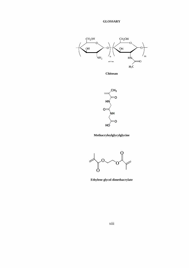
GLOSSARY
Chitosan
Methacryloylglycylglycine
Ethylene glycol dimethacrylate

xiv
Ammonium persulfate
Sodium metabisulphite
Tripolyphosphate

xv
OBJECTIVES
The present doctorate thesis aims at studying in detail the behaviour and properties of a
naturally derived semi-synthetic origin polymer, chitosan and its combination with a
synthetic polymer belonging to the class of poly(acrylamides). To accomplish the above
objective, micro/ nano particles as well as semi-interpenetrating hydrogel networks were
prepared for biomedical applications. Various physico-chemical characterizations of the
prepared materials have been performed and evaluated in detail.
Chitosan is a biodegradable polymer with great potential for various applications
due to its biocompatibility, high charge density, non-toxicity and mucoadhesivity. It is a
semi-crystalline polymer and most of its properties are known to be a function of the degree
of acetylated monomeric units. Much of the potential of chitosan as a biomaterial stems from
its cationic nature and high charge density in solution. The charge density allows chitosan to
form insoluble ionic complexes or complex coacervates with a wide variety of water-soluble
anionic polymers. Different strategies are adopted in this thesis to develop systems based on
chitosan which would offer better application for Regenerative Medicine applications.
As mentioned above, the degree of deacetylation (DD) that represents indeed the
number of acetylated amino glucosidic units and is one of the most important properties of
chitosan. A simple, rapid and reliable method for the determination of DD of chitosan is
essential. An economical and accurate determination of DD for highly acetylated amino
polysaccharides has always been a challenge for researchers dealing with chitin and chitosan.
Our aim was to prepare chitosan from its parent polymer chitin and to determine the DD
values using spectroscopic and thermal techniques. Different reaction parameters were
varied and using these data a statistical model was designed to define the best preparative
condition for such reactions.
The use of microsphere or bead-based therapies allow drug release to be carefully
tailored to the specific treatment sites through the choice and formulation of various drug–
polymer combinations. Chitosan beads are used to provide controlled release of many drugs
and to improve the bioavailability of degradable substances such as protein or enhance the
uptake of hydrophilic substances across the epithelial compartments. Chitosan possess a
unique capability of forming beads in the presence of non-toxic polyanion. We tried to
exploit this ability of chitosan for the loading of two model proteins Human Serum Albumin
(HSA) and Porcine Trypsin (PT). Both the proteins were successfully loaded into the beads
and their release behaviour was studied.
A number of studies have been conducted with the aim of using chitosan-based
nanoparticles as the carriers of drugs, vaccines and even DNA. Chitosan-based nanoparticles
xvi
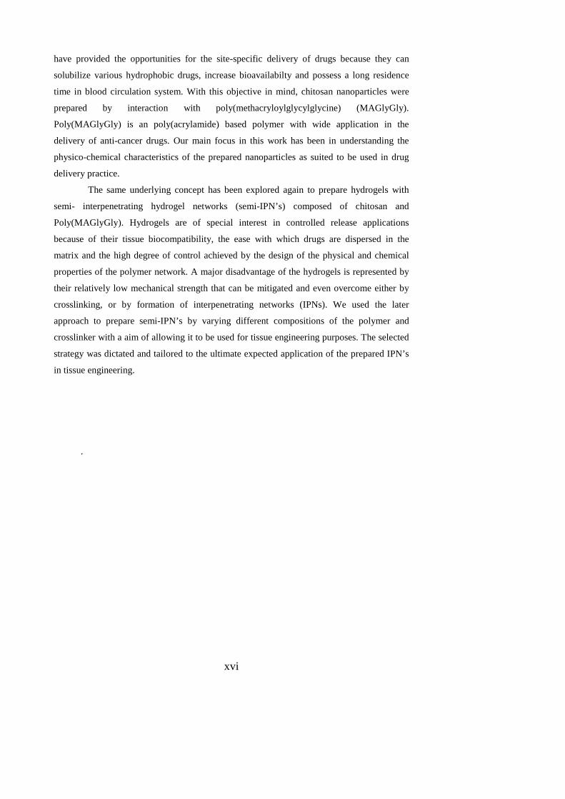
have provided the opportunities for the site-specific delivery of drugs because they can
solubilize various hydrophobic drugs, increase bioavailabilty and possess a long residence
time in blood circulation system. With this objective in mind, chitosan nanoparticles were
prepared by interaction with poly(methacryloylglycylglycine) (MAGlyGly).
Poly(MAGlyGly) is an poly(acrylamide) based polymer with wide application in the
delivery of anti-cancer drugs. Our main focus in this work has been in understanding the
physico-chemical characteristics of the prepared nanoparticles as suited to be used in drug
delivery practice.
The same underlying concept has been explored again to prepare hydrogels with
semi- interpenetrating hydrogel networks (semi-IPN’s) composed of chitosan and
Poly(MAGlyGly). Hydrogels are of special interest in controlled release applications
because of their tissue biocompatibility, the ease with which drugs are dispersed in the
matrix and the high degree of control achieved by the design of the physical and chemical
properties of the polymer network. A major disadvantage of the hydrogels is represented by
their relatively low mechanical strength that can be mitigated and even overcome either by
crosslinking, or by formation of interpenetrating networks (IPNs). We used the later
approach to prepare semi-IPN’s by varying different compositions of the polymer and
crosslinker with a aim of allowing it to be used for tissue engineering purposes. The selected
strategy was dictated and tailored to the ultimate expected application of the prepared IPN’s
in tissue engineering.
.
1
1. CHITOSAN- A VERSATILE MATERIAL FOR REGENERATIVE
MEDICINE APPLICATIONS
1.1. Abstract
Regenerative medicine, one of the upcoming fields in present and future life science, finally
aims at the restoration or replacement of lost or damaged organ or body part with
transplantation of new tissues in combination with supportive scaffolds and biomolecules.
Regenerative medicine is usually defined by connecting the fields of tissue engineering, stem
cell research, gene therapy and therapeutic cloning [1, 2]. Recently, functional biomaterial
research has been directed toward the development of new drug delivery systems and
improved scaffolds for regenerative medicine. In this regard, increasing attention has been
given to chitosan and its derivatives. Chitosan is becoming an undisputed biomolecule of
great potential because of its polyelectrolyte properties, including the presence of reactive
functional groups, gel-forming ability, high adsorption capacity, complete biodegradability,
bacteriostatic, and fungistatic, even anti-tumor influence [3]. Chitosan is also bio-compatible
and non-toxic for living tissues [4,5]. These investigations confirm the suitability and
extensive applications of chitosan in regenerative medicine. The present chapter outlines the
major new findings on the most common chitosan-based materials. Micro/nanoparticulate
and hydrogels are widely used forms of chitosan, a survey of the publications related to them
over the past decade has been done. Methods of their preparation, drug loading, release
characteristics, and applications are covered. Herein, the potential value of chitosan in tissue
engineering, wound healing and gene therapy have been mainly focused. The chemical
structure and relevant biological properties of chitosan for regenerative medicine have also
been summarized.
1.2. Introduction
The history of chitosan dates back to the last century, when Rouget [6] discussed the
deacetylated forms of the parent chitin natural polymer in 1859. During the past 20 years, a
substantial amount of work has been published on this polymer and its potential use in
various applications. Recently, chitosan has been considered for pharmaceutical formulation
and drug delivery applications in which attention has been focused on its absorption-
PHD THESIS – MAMONI DASH
2
enhancing, controlled release and bioadhesive properties. Synthesized from a naturally
occurring source, this polymer has been shown to be both biocompatible and biodegradable
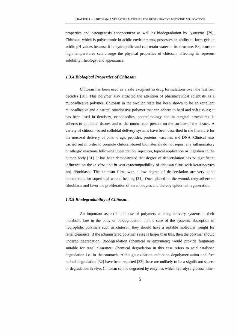
[7]. Chitosan is a linear copolymer of β-(1-4) linked 2-acetamido- 2-deoxy- β -D-
glucopyranose and 2-amino-2- deoxy- β -D-glycopyranose (figure. 1(a)). It is easily obtained
by deacetylation of chitin, a polysaccharide widely distributed in nature (e.g. crustaceans,
insects and certain fungi) [8,9]. Due to the limited solubility of chitin in aqueous solutions,
chitosan is more suitable for industrial applications [10]. Chitin and chitosan polymers are a
natural and a semi-synthetic desired aminopolysaccharides respectively having unique
structures, multidimensional properties, highly sophisticated functions and wide ranging
applications in biomedical and other industrial areas [11–13]. The positive attributes of
excellent biocompatibility and admirable biodegradability with ecological safety and low
toxicity with versatile biological activities such as antimicrobial activity and low
immunogenicity have provided ample opportunities for further development [14-19]. It has
become of great interest not only as a cheap and easily available resource but also as a new
functional biomaterial of high potential in various fields [20-22].
1.3. General Aspects of Chitosan
1.3.1 Structure of Chitosan
Chitosan [poly(1,4-β-D-glucopyranosamine)], is produced generally by partial
deacetylation of chitin obtained from the shells of crustaceans. Chitosan molecule is a
copolymer of N-acetyl-D-glucosamine and D-glucosamine available in different grades
depending upon the degree of deacetylated moieties (figure 1(a)) [23]. It is a polycationic
polymer that has one amino group and two hydroxyl groups in the repeating hexosaminide
residue (figure 1(b)). The sugar backbone consists of β-1,4-linked D-glucosamine with a
high degree of N-acetylation, a structure very similar to that of cellulose, except that the
acetylamino group replaces the hydroxyl group on the C2 position. Thus, chitosan is poly(
N-acetyl-2-amino-2-deoxy-D-glucopyranose), where the N-acetyl-2-amino-2-deoxy-D-
glucopyranose (or Glu-NH2) units are linked by (1→4)-β-glycosidic bonds[24]. Chitosan has
a rigid crystalline structure through inter- and intra-molecular hydrogen bonding.

CHAPTER 1 – CHITOSAN-A VERSATILE MATERIAL FOR REGENERATIVE MEDICINE APPLICATIONS
3
(a) (b)
Figure 1. (a) Structure of chitosan ; (b) Chemical structure of chitosan. Individual atoms are
numbered. Dashed lines denote O3―O5 hydrogen bonds. Two dihedral angles (φ, ψ) defining the
main chain conformation and one dihedral angle χ defining the O6 orientation are indicated.
1.3.2 Source & Availability of Chitosan
Chitin is the second most abundant polysaccharides in nature, cellulose being the
most abundant. Chitin is found in the exoskeleton of crustacea, insects, and some fungi. The
main commercial sources of chitin are the shell wastes of shrimp, lobster, krill and crab. In
the world several millions tons of chitin are harvested annually [24-26]. Chitosan is obtained
by the deacetylation of chitin. Treatment of chitin with an aqueous 40-45%(w/v) NaOH
solution at 90-120°C for 4-5 h results in N-deacetylation of chitin. The insoluble precipitate
is washed with water to give a crude sample of chitosan. The conditions used for
deacetylation determines the polymer molecular weight and the degree of deacetylation
(DD). Generally, further purification is necessary to prepare medical and pharmaceutical
grade chitosan.
1.3.3 Physicochemical Properties of Chitosan
Chitosan is insoluble at neutral and alkaline pH, but forms water-soluble salts with
inorganic and organic acids including glutamic, hydrochloric, lactic and acetic acids. Upon
PHD THESIS – MAMONI DASH
4
dissolution in acidic media, the amino groups of the polymer become protonated rendering
the molecule positively charged. The DD represents the proportion of D-glucosamine units
with respect to the total number of units. The properties of chitosan (e.g. pKa and solubility)
can be modified by changing the DD and formulation properties such as the pH and ionic
strength. At neutral pH, most chitosan molecules lose their charge and precipitate from
solution.
The primary amino groups on the molecule are reactive and provide sites for side
group attachment using a variety of mild reaction conditions, this property renders it to be an
easy molecule for side chain reactions and derivatization. In addition, the characteristic
features of chitosan such as being cationic, hemostatic and insoluble at high pH, can be
completely reversed by a sulfation process which can render the molecule anionic and water-
soluble, and also introduce anticoagulant properties [27].
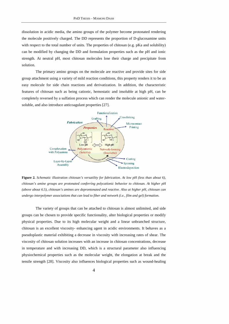
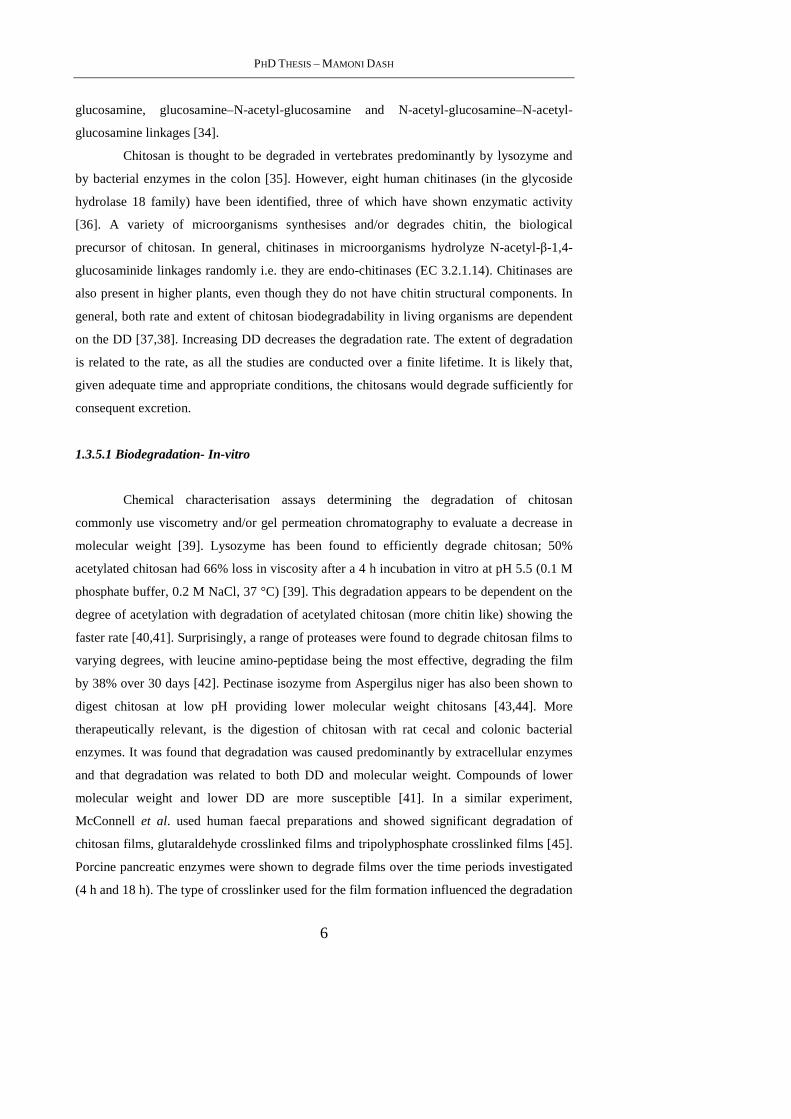
Figure 2. Schematic illustration chitosan’s versatility for fabrication. At low pH (less than about 6),
chitosan’s amine groups are protonated conferring polycationic behavior to chitosan. At higher pH
(above about 6.5), chitosan’s amines are deprontonated and reactive. Also at higher pH, chitosan can
undergo interpolymer associations that can lead to fiber and network (i.e., film and gel) formation.
The variety of groups that can be attached to chitosan is almost unlimited, and side
groups can be chosen to provide specific functionality, alter biological properties or modify
physical properties. Due to its high molecular weight and a linear unbranched structure,
chitosan is an excellent viscosity- enhancing agent in acidic environments. It behaves as a
pseudoplastic material exhibiting a decrease in viscosity with increasing rates of shear. The
viscosity of chitosan solution increases with an increase in chitosan concentrations, decrease
in temperature and with increasing DD, which is a structural parameter also influencing
physiochemical properties such as the molecular weight, the elongation at break and the
tensile strength [28]. Viscosity also influences biological properties such as wound-healing
CHAPTER 1 – CHITOSAN-A VERSATILE MATERIAL FOR REGENERATIVE MEDICINE APPLICATIONS
5
properties and osteogenesis enhancement as well as biodegradation by lysozyme [29].
Chitosan, which is polycationic in acidic environments, possesses an ability to form gels at
acidic pH values because it is hydrophilic and can retain water in its structure. Exposure to
high temperatures can change the physical properties of chitosan, affecting its aqueous
solubility, rheology, and appearance.
1.3.4 Biological Properties of Chitosan
Chitosan has been used as a safe excipient in drug formulations over the last two
decades [30]. This polymer also attracted the attention of pharmaceutical scientists as a
mucoadhesive polymer. Chitosan in the swollen state has been shown to be an excellent
mucoadhesive and a natural bioadhesive polymer that can adhere to hard and soft tissues; it
has been used in dentistry, orthopaedics, ophthalmology and in surgical procedures. It
adheres to epithelial tissues and to the mucus coat present on the surface of the tissues. A
variety of chitosan-based colloidal delivery systems have been described in the literature for
the mucosal delivery of polar drugs, peptides, proteins, vaccines and DNA. Clinical tests
carried out in order to promote chitosan-based biomaterials do not report any inflammatory
or allergic reactions following implantation, injection, topical application or ingestion in the
human body [31]. It has been demonstrated that degree of deacetylation has no significant
influence on the in vitro and in vivo cytocompatibility of chitosan films with keratinocytes
and fibroblasts. The chitosan films with a low degree of deacetylation are very good
biomaterials for superficial wound-healing [31]. Once placed on the wound, they adhere to
fibroblasts and favor the proliferation of keratinocytes and thereby epidermal regeneration.
1.3.5 Biodegradability of Chitosan
An important aspect in the use of polymers as drug delivery systems is their
metabolic fate in the body or biodegradation. In the case of the systemic absorption of
hydrophilic polymers such as chitosan, they should have a suitable molecular weight for
renal clearance. If the administered polymer's size is larger than this, then the polymer should
undergo degradation. Biodegradation (chemical or enzymatic) would provide fragments
suitable for renal clearance. Chemical degradation in this case refers to acid catalysed
degradation i.e. in the stomach. Although oxidation–reduction depolymerisation and free
radical degradation [32] have been reported [33] these are unlikely to be a significant source
or degradation in vivo. Chitosan can be degraded by enzymes which hydrolyse glucosamine–
PHD THESIS – MAMONI DASH
6
glucosamine, glucosamine–N-acetyl-glucosamine and N-acetyl-glucosamine–N-acetyl-
glucosamine linkages [34].
Chitosan is thought to be degraded in vertebrates predominantly by lysozyme and
by bacterial enzymes in the colon [35]. However, eight human chitinases (in the glycoside
hydrolase 18 family) have been identified, three of which have shown enzymatic activity
[36]. A variety of microorganisms synthesises and/or degrades chitin, the biological
precursor of chitosan. In general, chitinases in microorganisms hydrolyze N-acetyl-β-1,4-
glucosaminide linkages randomly i.e. they are endo-chitinases (EC 3.2.1.14). Chitinases are
also present in higher plants, even though they do not have chitin structural components. In
general, both rate and extent of chitosan biodegradability in living organisms are dependent
on the DD [37,38]. Increasing DD decreases the degradation rate. The extent of degradation
is related to the rate, as all the studies are conducted over a finite lifetime. It is likely that,
given adequate time and appropriate conditions, the chitosans would degrade sufficiently for
consequent excretion.
1.3.5.1 Biodegradation- In-vitro
Chemical characterisation assays determining the degradation of chitosan
commonly use viscometry and/or gel permeation chromatography to evaluate a decrease in
molecular weight [39]. Lysozyme has been found to efficiently degrade chitosan; 50%
acetylated chitosan had 66% loss in viscosity after a 4 h incubation in vitro at pH 5.5 (0.1 M
phosphate buffer, 0.2 M NaCl, 37 °C) [39]. This degradation appears to be dependent on the
degree of acetylation with degradation of acetylated chitosan (more chitin like) showing the
faster rate [40,41]. Surprisingly, a range of proteases were found to degrade chitosan films to
varying degrees, with leucine amino-peptidase being the most effective, degrading the film
by 38% over 30 days [42]. Pectinase isozyme from Aspergilus niger has also been shown to
digest chitosan at low pH providing lower molecular weight chitosans [43,44]. More
therapeutically relevant, is the digestion of chitosan with rat cecal and colonic bacterial
enzymes. It was found that degradation was caused predominantly by extracellular enzymes
and that degradation was related to both DD and molecular weight. Compounds of lower
molecular weight and lower DD are more susceptible [41]. In a similar experiment,
McConnell et al. used human faecal preparations and showed significant degradation of
chitosan films, glutaraldehyde crosslinked films and tripolyphosphate crosslinked films [45].
Porcine pancreatic enzymes were shown to degrade films over the time periods investigated
(4 h and 18 h). The type of crosslinker used for the film formation influenced the degradation
CHAPTER 1 – CHITOSAN-A VERSATILE MATERIAL FOR REGENERATIVE MEDICINE APPLICATIONS
7
rate; glutaraldehyde to a greater degree than tripolyphosphate, an effect that was more
pronounced with the high (310–600 kDa) and medium (190–310 kDa) molecular weight
chitosans.
1.3.5.2 Biodegradation- In-vivo
Chitosan degradation after intravenous administration has been reported scarcely. It
is somewhat unclear what the mechanism of degradation is when chitosan is injected
intravenously. Some authors are of the view that distribution degradation and elimination
processes are strongly dependent on molecular weight. Possible sites of degradation, inferred
due to the localisation of chitosan, may be the liver and kidney. In one of the few studies
reported, chitosan oligosaccharides were found to upregulate lysozyme activity in the blood
of rabbits injected intravenously with 7.1–8.6 mg/kg [46]. Chitosan has also been
administered subcutaneously, in most cases as an implant. A proposed skin substitute of
glutaraldehyde crosslinked chitosan/collagen was relatively stable over time compared to
collagen alone when implanted subcutaneously in rabbits [47]. Oral administration of
chitosan has shown some degradation in the gastrointestinal tract. The digestion of chitosan,
occurring predominantly in the gut, was found to be species dependent with hens and
broilers being more efficient digesters (67–98% degradation after oral ingestion) than rabbits
(39–83% degradation) [48].
1.3.6 Biodistribution of Chitosan
One of the most studied aspects of chitosan is its biodistribution, especially using
methods other than intravenous administration. This distribution is related to all aspects of
the chitosan formulation from the molecular weight and DD to the size of the delivery
vehicle. In the case of a nanoparticulate formulation, the kinetics and biodistribution will
initially be controlled by the size and charge of the nanoparticles and not by chitosan.
However, after particle decomposition to chitosan and free drug, inside the cells or target
tissue, free chitosan will distribute in the body and eliminate accordingly. Elimination
processes may be preceded by biodegradation. To understand chitosan biodistribution the
kinetics of its labeled (radio or fluorescent) modifications should be followed, assuming that
the label is neither labile nor affecting the physicochemical properties of the chitosan.
PHD THESIS – MAMONI DASH
8
1.3.6.1 Distribution after Intravenous Administration
In an attempt to prepare Holmium-166 based radiopharmaceuticals for tumours,
Suzuki et al. [49] administered chitosan (700 kDa) with Holmium-166 in a chelate complex
form and studied its distribution in rats and mice. They found that 72 h after intravenous
administration, 4.2% and 4.8% of the radioactivity was recovered in the urine and feces
respectively, whereas 90.6% was found in the carcass [49]. Banerjee et al. describe the
distribution of intravenously injected 99mTc labeled nanoparticles (<100 nm) in Swiss
albino mice. Nanoparticles were tested for radiolabel stability and 80% of the radioactivity
was associated with the particles after 3 h. Nanoparticles were administered in mice and an
apparent evasion of the reticuloendothelial system (RES) was suggested as radioactivity
decreased in organs of this system but remained stable in the blood after 1 h [50].
Unfortunately, the nanoparticles were not sufficiently stable to look at long term
distributions. However accumulation in the liver was detected.
Richardson et al. reported on radio-labeled chitosan (125I) of three different molecular
weight fractions (<5 kDa, 5–10 kDa and >10 kDa) and biodistribution was assessed at 5 min
and 1 h in male Wistar rats [51]. The authors found ~45% of the recovered dose of the <5
kDa chitosan in the blood at 5 min and ~30% remaining in the blood at 1 h. This was not the
case for the 5–10 kDa and >10 kDa chitosans where the 5 min blood recovery was ~15% and
~12% and the 1h ~8% and ~4% respectively. The main organ of uptake appears to be the
liver, where accumulation was found to increase with increasing molecular weight. However,
there was a recovery of less than 60% of the total administered dose (in harvested tissue) in
all cases and it was not normalized to the tissue weight [51]. All three studies found the liver
to be a significant site of accumulation; this could be due to this organ being a primary site of
metabolism as seen with radio-labeled dextran [52].
A potential method to study native chitosan without significant modification would
be to use 14C as a label e.g. in the food source for the animal/fungi producing the chitin so
that the saccharide backbone is labeled, as detection of native chitosan is somewhat of a
challenge [53].
1.3.6.2 Distribution after intraperitoneal administration
FITC-labeled chitosan (50% DD, 100 kDa) was prepared by FITC coupling and
chromatographed for purification. This labeled chitosan was administered intraperitoneally
and it was completely absorbed form the peritoneal cavity (no evidence in abdominal fluid
CHAPTER 1 – CHITOSAN-A VERSATILE MATERIAL FOR REGENERATIVE MEDICINE APPLICATIONS
9
after 14 h). FITC-chitosan was found to be predominantly localised in the kidney at 1 h in a
mouse model. There was a rapid renal excretion rate (25% at 1 h, 100% in 14 h) with
evidence of degradation due to a decrease in the molecular weight [54].
1.3.6.3 Tissue distribution after oral administration
Oral dosage forms use chitosan as an excipient, although chitosan does not strictly
fit the definition of excipient as it has many biological effects. It has been suggested that
chitosan chelates fat and reduces cholesterol but this, and its mechanism, is somewhat
debatable [55,56]. Apart from the effect that chitosan may have on bile salts and
gastrointestinal milieu, the uptake of chitosan into the bloodstream is generally not
investigated in oral administration studies. Chitosan's systemic absorption and distribution
from this route of delivery has been observed to be largely dependent on the molecular
weight. It has been seen in some cases that oligomers showed some absorption whereas
larger molecular weight chitosans were excreted without being absorbed. This effect was
seen with FITC-labeled chitosans with 3.8 kDa (88.4% DD) chitosan having the greatest
plasma concentration after oral administration vs 230 kDa (84.9% DD) having almost no
uptake. Increasing molecular weight was seen to decrease the plasma concentration in this,
one of the only studies investigating plasma concentration after oral administration [57].
2.1.6.4 Intracellular chitosan distribution
Although native chitosan has not been investigated, the intracellular uptake and
distribution of chitosan/DNA complexes have been studied in vitro [58-60]. Chitosan
polyplex uptake at 37 °C was 3-fold higher than at 4 °C [58] but this could be due to
increased interaction and not an ATP dependent endocytic mechanism. The authors
suggested nuclear localization and they also stated little dissociation of the DNA from the
chitosan. In a more comprehensive study, Leong et al. stained for lysosomes and found some
co-localization with chitosan DNA nanoparticles. However, the majority of the polyplexes
were found in the cytosol [59]. A complex of doxorubicin with chitosan has also been
studied; complexes enter cells through an endocytic mechanisms which was not further
elucidated [61].
PHD THESIS – MAMONI DASH
10
1.3.7 Toxicity of Chitosan
Chitosan is widely regarded as being a non-toxic, biologically compatible polymer
[62]. It is approved for dietary applications in Japan, Italy and Finland [63] and it has been
approved by the FDA for use in wound dressings [64]. The modifications perfomed on
chitosan could make it more or less toxic and any residual reactants should be carefully
removed.
1.3.7.1 In-vitro toxicity
In a series of articles Schipper et al. described the effects of chitosans with differing
molecular weights and DD on CaCo-2 cells, HT29-H and in situ rat jejunum. Toxicity was
found to be DD and molecular weight dependent. At high DD the toxicity is related to the
molecular weight and the concentration, at lower DD toxicity is less pronounced and less
related to the molecular weight. However most of the chitosans tested did not increase
dehydrogenase activity significantly in the concentration range tested (1–500 µg/ml) on
Caco-2 cells. The in situ rat jejunum study showed no increase in LDH activity with any of
the chitosans tested (50 µg/ml) [65,66]. A study that reveals safety of materials is the red cell
haemolysis assay. Haemolysis was not observed (<10%) over 1 h and 5 h with chitosans of
<5 kDa, 5–10 kDa and >10 kDa at concentrations of up to 5 mg/ml [51]. As well, no red
blood cell lysis was observed with paclitaxel chitosan micelles at 0.025 mg/ml [67].
Interestingly, chitosan and its derivatives seem to be toxic to several bacteria [68],
fungi [69] and parasites [70]. This pathogen related toxicity is an effect which could aid in
infectious disease control. When emulsions containing chitosans were tested, bacterial
inhibition took place in acidic solutions pH 5–5.3, and a 87 kDa 92% DD chitosan was more
effective than a 532 kDa 73% DD chitosan against both Pseudomonas aeruginosa and
Staphylococcus aureus. A lipid emulsion of the same chitosans was found to have
antimycotic effect against Candida albicans and Aspergillus niger [68]. In tests of
meglumine antimoniate against Leishmania infantum it was found that the chitosan excipient
had anti-parasitic properties (IC50 112.64± 0.53 mg/ml for promastigotes and 100.81±26.45
mg/ml for amastigotes) [70]. None of these studies hypothesized a mechanism of action for
the inhibitory effect observed.
CHAPTER 1 – CHITOSAN-A VERSATILE MATERIAL FOR REGENERATIVE MEDICINE APPLICATIONS
11
1.3.7.2 In-vivo toxicity
In vivo toxicity particularly after long term administration is of high importance for
the design of drug delivery forms based on chitosan. In a relatively long study (65 days), no
detrimental effect on body weight was found when chitosan oligosaccharides were injected
(7.1–8.6 mg/kg over 5 days). An increase in lysozyme activity was apparent on the first day
post injections [71].
Rao et al. stated no “significant toxic effects” of chitosan in acute toxicity tests in
mice, no eye or skin irritation in rabbits and guinea pigs respectively. In the same study it
was also concluded that chitosan was not pyrogenic. However, no concentration or DD of the
chitosan used was noted [72]. Even though no dose is stated in his work , no detrimental
effects were noted by Richardson et al. [51]. The LD50 of paclitaxel chitosan micelles in
mice was 72.16 mg/kg, no anaphylaxis was observed in guinea pigs and no intravenous
irritation was observed histopathologically in rabbits at 6 mg/kg [67]. No adverse effects at
3.3–4 mg/kg were reported by Banerjee et al. [50]. In a study on fat chelation, 4.5 g/day
chitosan (molecular weight and DD not noted) in humans was not reported toxic, although
no significant reduction in fat was found [73]. Arai et al. found that chitosan has an LD50
comparable to sucrose of >16 g/kg in oral administration to mice [74]. No oral toxicity was
found in mice treated with 100 mg/kg chitosan nanoparticles (80 kDa, 80% DD) [75].
Exposure of rat nasal mucosa to chitosan solutions at 0.5% (w/v) over 1 h caused no
significant changes in mucosal cell morphology compared to control [76]. From most studies
reported it appears that chitosan shows minimal toxic effects and this justifies its selection as
a safe material in drug delivery.
1.4. Chitosan Based Systems for Regenerative Medicine Applications
1.4.1 Chitosan Micro/nano Particles
If DD and molecular weight of chitosan can be controlled, then it would be a
material of choice for developing micro/nanoparticles. Chitosan has many advantages, and
these include its ability to control the release of active agents and the avoid use of hazardous
organic solvents while fabricating particles since it is soluble in aqueous acidic solution. In
view of the above-mentioned properties, chitosan is extensively used in developing drug
delivery systems [77–84]. Particularly, chitosan has been used in the preparation of
mucoadhesive formulations [85,86,76,87], improving the dissolution rate of the poorly

PHD THESIS – MAMONI DASH
12
soluble drugs [80,88,89], drug targeting [90,91] and enhancement of peptide absorption
[86,76,92]. Different types of chitosan based drug delivery systems are summarized in Table
1. The micro/nanoparticulate drug delivery systems offer numerous advantages over the
conventional dosage forms. These include improved efficacy, reduced toxicity and improved
patient compliance [93,94-96]. In the present section we have addressed the trends in the
area of micro/nanoparticulate chitosan-based drug delivery systems. Literature of the past
decade has been covered and results are evaluated.
Table 1 Chitosan based drug delivery systems prepared by different methods.
Type of system Method of preparation
Tablets Matrix coating
Capsules Capsule shell
Microspheres
Emulsion cross-linking
Coacervation/Precipitation
Spray drying
Ionic gelation
Sieving method
Nanoparticles Emulsion-droplet coalescence
Coacervation/Precipitation
Beads Coacervation/Precipitation
Films Solution casting
Gel Crosslinking
1.4.1.1 Methods for the preparation of Chitosan micro/nanoparticles
Different methods have been used to prepare chitosan particulate systems. Selection
of any of the methods depends upon factors such as particle size requirement, thermal and
chemical stability of the active agent, reproducibility of the release kinetic profiles, stability
of the final product and residual toxicity associated with the final product. However,
selection of any of these methods depends upon the nature of the active molecule as well as
the type of the delivery device.
CHAPTER 1 – CHITOSAN-A VERSATILE MATERIAL FOR REGENERATIVE MEDICINE APPLICATIONS
13
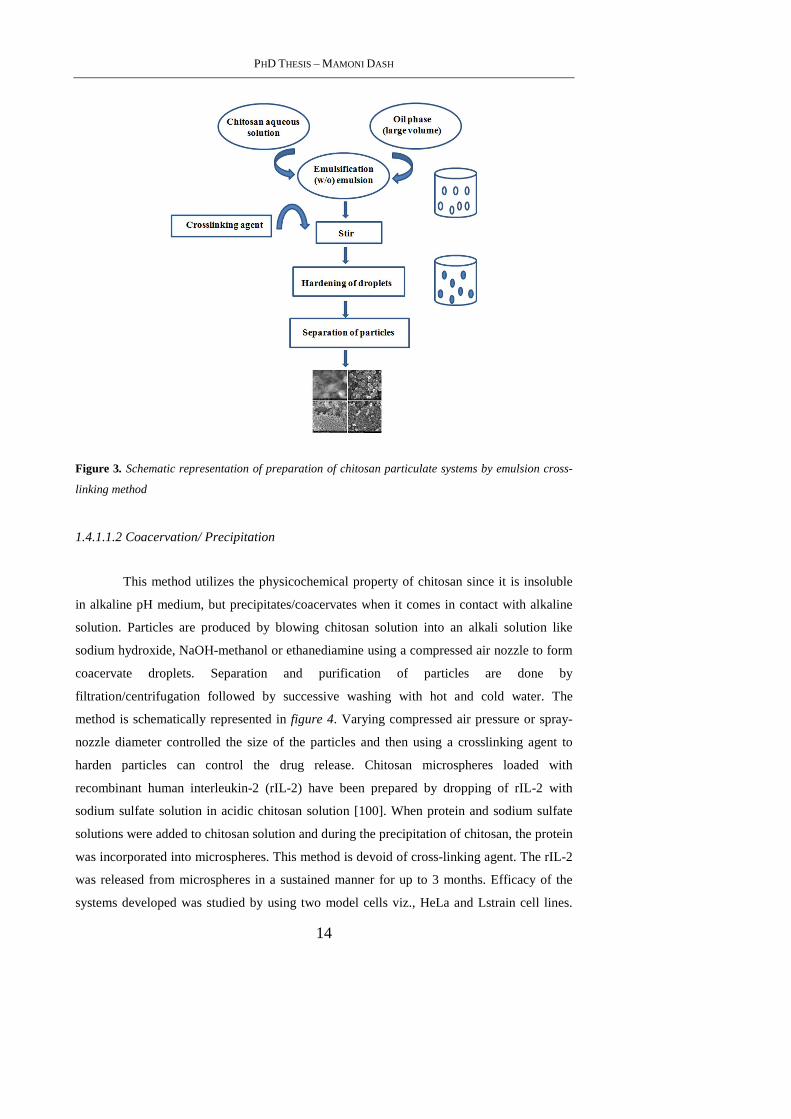
1.4.1.1.1 Emulsion crosslinking
This method utilizes the reactive functional amine group of chitosan to cross-link
with the possible reactive groups of the cross-linking agent. In this method, a water-in-oil
(w/o) emulsion is prepared by emulsifying the chitosan aqueous solution in the oil phase.
Aqueous droplets are stabilized using a suitable surfactant. The stable emulsion is cross-
linked by using an appropriate cross-linking agent to harden the droplets. Microspheres are
filtered and washed repeatedly with alcohol and then dried [97]. By this method, size of the
particles can be controlled by controlling the size of aqueous droplets. However, the particle
size of final product depends upon the extent of cross-linking agent used while hardening in
addition to speed of stirring during the formation of emulsion. This method is schematically
represented in figure 3. The emulsion cross-linking method has few drawbacks since it
involves tedious procedures as well as use of harsh cross-linking agents, which might
possibly induce chemical reactions with the active agent. Also, complete removal of the un-
reacted crosslinking agent may be difficult in this process.
Agnihotri et al. [98] have used the emulsion crosslinking method to prepare
chitosan microspheres to encapsulate diclofenac sodium using three crosslinking agents viz,
glutaraldehyde, sulfuric acid and heat treatment. Microspheres were spherical with smooth
surfaces. The size of the microparticles ranged between 40 and 230 µm. Among the three
cross-linking agents used, glutaraldehyde cross-linked microspheres showed the slowest
release rates while a quick release of diclofenac sodium was observed by the heat cross-
linked microspheres. Sankar et al. [99] prepared the chitosan-based pentazocine
microspheres for intranasal delivery. Formulation parameters such as drug loading, polymer
concentration, stirring speed during cross-linking and oil phase were altered to develop
microspheres having good in vivo performance. In vivo studies indicated a significantly
improved bioavailability of pentazocine. Application of in vitro data to various kinetic
models indicated that these systems followed the diffusion controlled release kinetics.
PHD THESIS – MAMONI DASH
14
Figure 3. Schematic representation of preparation of chitosan particulate systems by emulsion cross-
linking method
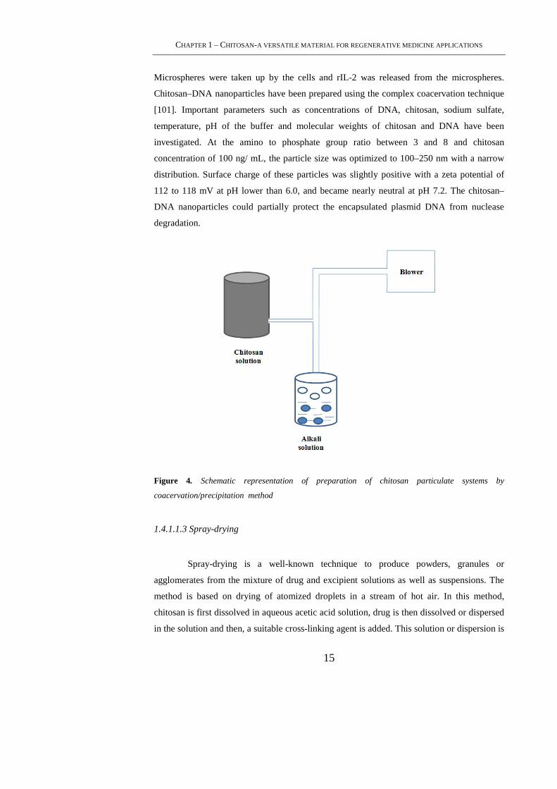
1.4.1.1.2 Coacervation/ Precipitation
This method utilizes the physicochemical property of chitosan since it is insoluble
in alkaline pH medium, but precipitates/coacervates when it comes in contact with alkaline
solution. Particles are produced by blowing chitosan solution into an alkali solution like
sodium hydroxide, NaOH-methanol or ethanediamine using a compressed air nozzle to form
coacervate droplets. Separation and purification of particles are done by
filtration/centrifugation followed by successive washing with hot and cold water. The
method is schematically represented in figure 4. Varying compressed air pressure or spray-
nozzle diameter controlled the size of the particles and then using a crosslinking agent to
harden particles can control the drug release. Chitosan microspheres loaded with
recombinant human interleukin-2 (rIL-2) have been prepared by dropping of rIL-2 with
sodium sulfate solution in acidic chitosan solution [100]. When protein and sodium sulfate
solutions were added to chitosan solution and during the precipitation of chitosan, the protein
was incorporated into microspheres. This method is devoid of cross-linking agent. The rIL-2
was released from microspheres in a sustained manner for up to 3 months. Efficacy of the
systems developed was studied by using two model cells viz., HeLa and Lstrain cell lines.
CHAPTER 1 – CHITOSAN-A VERSATILE MATERIAL FOR REGENERATIVE MEDICINE APPLICATIONS
15
Microspheres were taken up by the cells and rIL-2 was released from the microspheres.
Chitosan–DNA nanoparticles have been prepared using the complex coacervation technique
[101]. Important parameters such as concentrations of DNA, chitosan, sodium sulfate,
temperature, pH of the buffer and molecular weights of chitosan and DNA have been
investigated. At the amino to phosphate group ratio between 3 and 8 and chitosan
concentration of 100 ng/ mL, the particle size was optimized to 100–250 nm with a narrow
distribution. Surface charge of these particles was slightly positive with a zeta potential of
112 to 118 mV at pH lower than 6.0, and became nearly neutral at pH 7.2. The chitosan–
DNA nanoparticles could partially protect the encapsulated plasmid DNA from nuclease
degradation.
Figure 4. Schematic representation of preparation of chitosan particulate systems by
coacervation/precipitation method
1.4.1.1.3 Spray-drying
Spray-drying is a well-known technique to produce powders, granules or
agglomerates from the mixture of drug and excipient solutions as well as suspensions. The
method is based on drying of atomized droplets in a stream of hot air. In this method,
chitosan is first dissolved in aqueous acetic acid solution, drug is then dissolved or dispersed
in the solution and then, a suitable cross-linking agent is added. This solution or dispersion is

PHD THESIS – MAMONI DASH
16
then atomized in a stream of hot air. Atomization leads to the formation of small droplets,
from which solvent evaporates instantaneously leading to the formation of free flowing
particles [102]. Various process parameters are to be controlled to get the desired size of
particles. Particle size depends upon the size of nozzle, spray flow rate, atomization pressure,
inlet air temperature and extent of crosslinking. This method is however more commonly
used for the preparation of microparticles than for nanoparticles. Huang et al. [103] prepared
chitosan microspheres by the spray-drying method using type-A gelatin and ethylene oxide–
propylene oxide block copolymer as modifiers. Surface morphology and surface charges of
the prepared microspheres were investigated using SEM and microelectrophoresis. Shape,
size and surface morphology of the microspheres were significantly influenced by the
concentration of gelatin. Betamethasone disodium phosphate-loaded microspheres
demonstrated a good drug stability (less 1% hydrolysis product), high entrapment efficiency
(95%) and positive surface charge (37.5 mV). In vitro drug release from the microspheres
was related to gelatin content. Microspheres containing gelatin/chitosan ratio of 0.4–0.6
(w/w) showed a prolonged release up to 12 h. In another study [104], vitamin D2 (VD2),
also called as ergocalciferol, was efficiently encapsulated into chitosan microspheres
prepared by spray-drying method. The microencapsulated product was coated with ethyl
cellulose. The sustained release property of VD2 microspheres was used for the treatment of
prostatic disease [105].
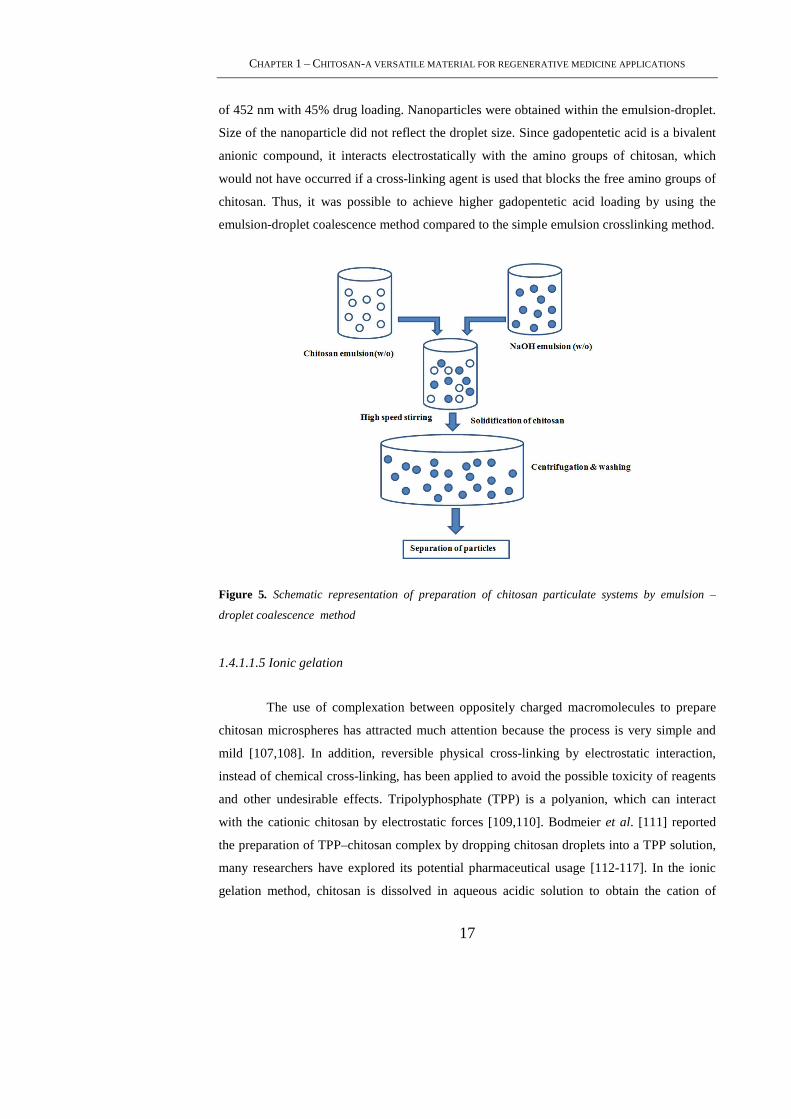
1.4.1.1.4 Emulsion-droplet coalescence method
The novel emulsion-droplet coalescence method was developed by Tokumitsu et al.
[106], which utilizes the principles of both emulsion cross-linking and precipitation.
However, in this method, instead of cross-linking the stable droplets, precipitation is induced
by allowing coalescence of chitosan droplets with NaOH droplets. First, a stable emulsion
containing aqueous solution of chitosan along with drug is produced in liquid paraffin oil and
then, another stable emulsion containing chitosan aqueous solution of NaOH is produced in
the same manner. When both emulsions are mixed under high-speed stirring, droplets of
each emulsion would collide at random and coalesce, thereby precipitating chitosan droplets
to give small size particles. The method is schematically shown in figure 5. Gadopentetic
acid-loaded chitosan nanoparticles have been prepared by this method for gadolinium
neutroncapture therapy. Particle size depends upon the type of chitosan, i.e., as the %
deacetylation degree of chitosan decreased, particle size increased, but drug content
decreased. Particles produced using 100% deacetylated chitosan had the mean particle size
CHAPTER 1 – CHITOSAN-A VERSATILE MATERIAL FOR REGENERATIVE MEDICINE APPLICATIONS
17
of 452 nm with 45% drug loading. Nanoparticles were obtained within the emulsion-droplet.
Size of the nanoparticle did not reflect the droplet size. Since gadopentetic acid is a bivalent
anionic compound, it interacts electrostatically with the amino groups of chitosan, which
would not have occurred if a cross-linking agent is used that blocks the free amino groups of
chitosan. Thus, it was possible to achieve higher gadopentetic acid loading by using the
emulsion-droplet coalescence method compared to the simple emulsion crosslinking method.
Figure 5. Schematic representation of preparation of chitosan particulate systems by emulsion –
droplet coalescence method
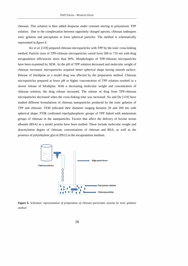
1.4.1.1.5 Ionic gelation
The use of complexation between oppositely charged macromolecules to prepare
chitosan microspheres has attracted much attention because the process is very simple and
mild [107,108]. In addition, reversible physical cross-linking by electrostatic interaction,
instead of chemical cross-linking, has been applied to avoid the possible toxicity of reagents
and other undesirable effects. Tripolyphosphate (TPP) is a polyanion, which can interact
with the cationic chitosan by electrostatic forces [109,110]. Bodmeier et al. [111] reported
the preparation of TPP–chitosan complex by dropping chitosan droplets into a TPP solution,
many researchers have explored its potential pharmaceutical usage [112-117]. In the ionic
gelation method, chitosan is dissolved in aqueous acidic solution to obtain the cation of
PHD THESIS – MAMONI DASH
18
chitosan. This solution is then added dropwise under constant stirring to polyanionic TPP
solution. Due to the complexation between oppositely charged species, chitosan undergoes
ionic gelation and precipitates to form spherical particles. The method is schematically
represented in figure 6.
Ko et al. [118] prepared chitosan microparticles with TPP by the ionic cross-linking
method. Particle sizes of TPP-chitosan microparticles varied from 500 to 710 nm with drug
encapsulation efficiencies more than 90%. Morphologies of TPP-chitosan microparticles
have been examined by SEM. As the pH of TPP solution decreased and molecular weight of
chitosan increased, microparticles acquired better spherical shape having smooth surface.
Release of felodipine as a model drug was affected by the preparation method. Chitosan
microparticles prepared at lower pH or higher concentration of TPP solution resulted in a
slower release of felodipine. With a decreasing molecular weight and concentration of
chitosan solution, the drug release increased. The release of drug from TPP-chitosan
microparticles decreased when the cross-linking time was increased. Xu and Du [119] have
studied different formulations of chitosan nanoparticles produced by the ionic gelation of
TPP and chitosan. TEM indicated their diameter ranging between 20 and 200 nm with
spherical shape. FTIR confirmed tripolyphosphoric groups of TPP linked with ammonium
groups of chitosan in the nanoparticles. Factors that affect the delivery of bovine serum
albumin (BSA) as a model protein have been studied. These include molecular weight and
deacetylation degree of chitosan, concentrations of chitosan and BSA, as well as the
presence of polyethylene glycol (PEG) in the encapsulation medium.
Figure 6. Schematic representation of preparation of chitosan particulate systems by ionic gelation
method
CHAPTER 1 – CHITOSAN-A VERSATILE MATERIAL FOR REGENERATIVE MEDICINE APPLICATIONS
19
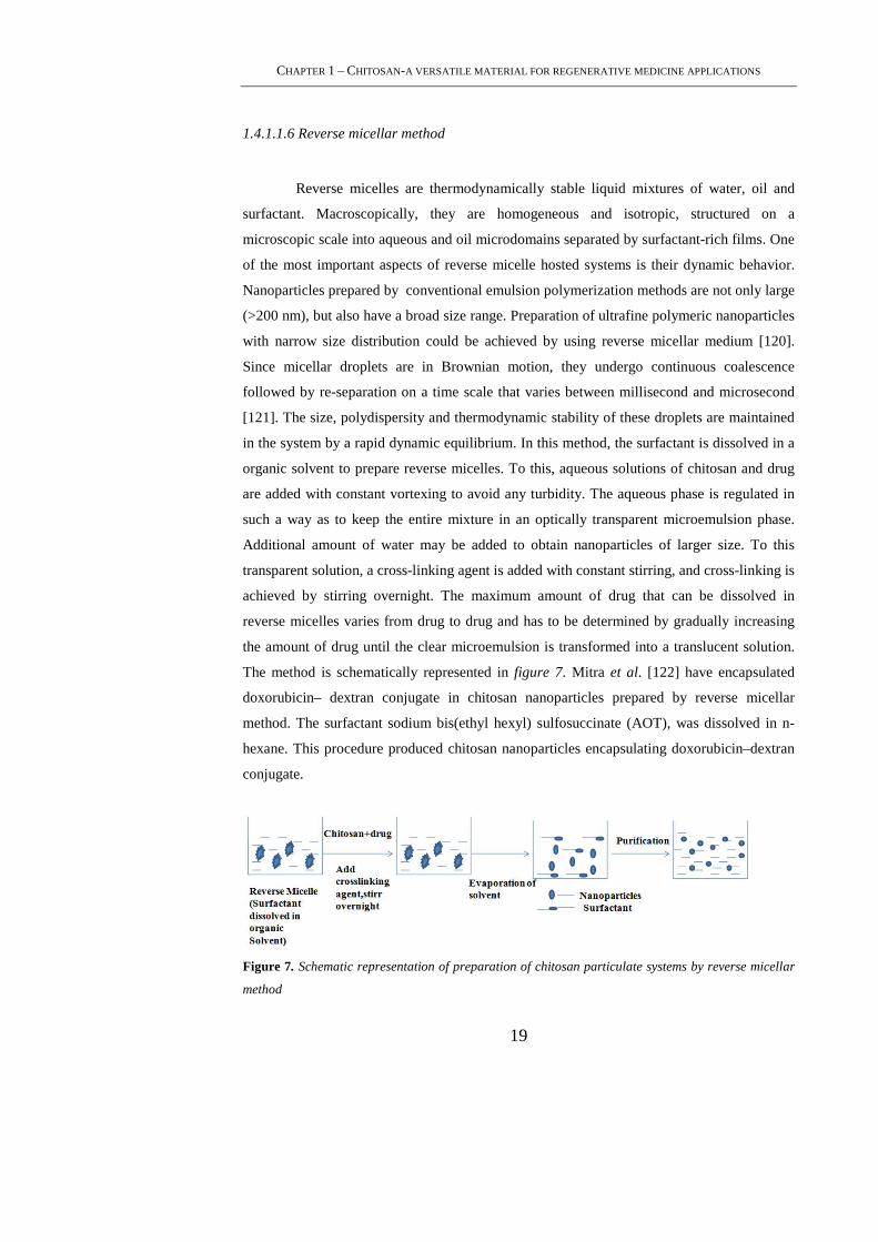
1.4.1.1.6 Reverse micellar method
Reverse micelles are thermodynamically stable liquid mixtures of water, oil and
surfactant. Macroscopically, they are homogeneous and isotropic, structured on a
microscopic scale into aqueous and oil microdomains separated by surfactant-rich films. One
of the most important aspects of reverse micelle hosted systems is their dynamic behavior.
Nanoparticles prepared by conventional emulsion polymerization methods are not only large
(>200 nm), but also have a broad size range. Preparation of ultrafine polymeric nanoparticles
with narrow size distribution could be achieved by using reverse micellar medium [120].
Since micellar droplets are in Brownian motion, they undergo continuous coalescence
followed by re-separation on a time scale that varies between millisecond and microsecond
[121]. The size, polydispersity and thermodynamic stability of these droplets are maintained
in the system by a rapid dynamic equilibrium. In this method, the surfactant is dissolved in a
organic solvent to prepare reverse micelles. To this, aqueous solutions of chitosan and drug
are added with constant vortexing to avoid any turbidity. The aqueous phase is regulated in
such a way as to keep the entire mixture in an optically transparent microemulsion phase.
Additional amount of water may be added to obtain nanoparticles of larger size. To this
transparent solution, a cross-linking agent is added with constant stirring, and cross-linking is
achieved by stirring overnight. The maximum amount of drug that can be dissolved in
reverse micelles varies from drug to drug and has to be determined by gradually increasing
the amount of drug until the clear microemulsion is transformed into a translucent solution.
The method is schematically represented in figure 7. Mitra et al. [122] have encapsulated
doxorubicin– dextran conjugate in chitosan nanoparticles prepared by reverse micellar
method. The surfactant sodium bis(ethyl hexyl) sulfosuccinate (AOT), was dissolved in n-
hexane. This procedure produced chitosan nanoparticles encapsulating doxorubicin–dextran
conjugate.
Figure 7. Schematic representation of preparation of chitosan particulate systems by reverse micellar
method
PHD THESIS – MAMONI DASH
20
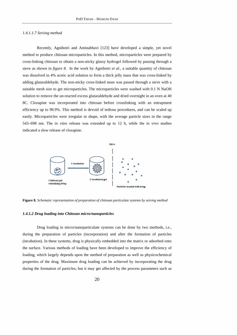
1.4.1.1.7 Seiving method
Recently, Agnihotri and Aminabhavi [123] have developed a simple, yet novel
method to produce chitosan microparticles. In this method, microparticles were prepared by
cross-linking chitosan to obtain a non-sticky glassy hydrogel followed by passing through a
sieve as shown in figure 8. In the work by Agnihotri et al., a suitable quantity of chitosan
was dissolved in 4% acetic acid solution to form a thick jelly mass that was cross-linked by
adding glutaraldehyde. The non-sticky cross-linked mass was passed through a sieve with a
suitable mesh size to get microparticles. The microparticles were washed with 0.1 N NaOH
solution to remove the un-reacted excess glutaraldehyde and dried overnight in an oven at 40
8C. Clozapine was incorporated into chitosan before crosslinking with an entrapment
efficiency up to 98.9%. This method is devoid of tedious procedures, and can be scaled up
easily. Microparticles were irregular in shape, with the average particle sizes in the range
543–698 nm. The in vitro release was extended up to 12 h, while the in vivo studies
indicated a slow release of clozapine.
Figure 8. Schematic representation of preparation of chitosan particulate systems by seiving method
1.4.1.2 Drug loading into Chitosan micro/nanoparticles
Drug loading in micro/nanoparticulate systems can be done by two methods, i.e.,
during the preparation of particles (incorporation) and after the formation of particles
(incubation). In these systems, drug is physically embedded into the matrix or adsorbed onto
the surface. Various methods of loading have been developed to improve the efficiency of
loading, which largely depends upon the method of preparation as well as physicochemical
properties of the drug. Maximum drug loading can be achieved by incorporating the drug
during the formation of particles, but it may get affected by the process parameters such as
CHAPTER 1 – CHITOSAN-A VERSATILE MATERIAL FOR REGENERATIVE MEDICINE APPLICATIONS
21
method of preparation, presence of additives, etc. Both water-soluble and water-insoluble
drugs can be loaded into chitosan-based particulate systems. Water soluble drugs are mixed
with chitosan solution to form a homogeneous mixture, and then, particles can be produced
by any of the methods discussed before.
Water-insoluble drugs and drugs that can precipitate in acidic pH solutions can be
loaded after the formation of particles by soaking the preformed particles with the saturated
solution of drug. Diclofenac sodium, which precipitates in acidic pH conditions, has been
loaded by the soaking method [98]. In this method, loading depends upon the swelling of
particles in water. Percentage loading of drug decreased with increasing cross-linking due to
decreased swelling. Water-insoluble drugs can also be loaded using the multiple emulsion
technique. In this method, drug is dissolved in a suitable solvent and then emulsified in
chitosan solution to form an oil-in-water (o/w) type emulsion. Sometimes, drug can be
dispersed into chitosan solution by using a surfactant to get the suspension. Thus, prepared
o/w emulsion or suspension can be further emulsified into liquid paraffin to get the oil-water-
oil (o/w/o) multiple emulsion. The resulting droplets can be hardened by using a suitable
cross-linking agent. Hejazi and Amiji [124] have prepared chitosan microspheres by ionic
cross-linking and precipitation with sodium sulfate. Two different methods were used for
drug loading. In method I, tetracycline was mixed with chitosan solution before simultaneous
cross– linking and precipitation. In method II, drug was incubated with the pre-formed
microspheres for 48h. Cumulative amount of tetracycline that was released from chitosan
microspheres and stability of drug was examined in different pH media at 37 °C.
Microspheres with a spherical shape having an average diameter of 2– 3 nm were formed.
When drug was added to chitosan solution before cross-linking and precipitation, only 8%
(w/w) was optimally incorporated in the final microsphere formulation. When drug was
incubated with the pre-formed microspheres, a maximum of 69% (w/w) could be loaded.
About 30% of tetracycline either in solution or when released from the microspheres was
found to degrade at pH 1.2 in 12 h. Preliminary results of this study suggested that chitosan
microspheres can be used to incorporate antibiotic drugs, which may be effective when
administered locally in the stomach against H. pylori.
1.4.1.3 Drug release & release kinetics
Drug release from chitosan-based particulate systems depends upon the extent of
cross– linking, morphology, size and density of the particulate system, physicochemical
properties of the drug as well as the presence of adjuvants. In vitro release also depends upon
PHD THESIS – MAMONI DASH
22
pH, polarity and presence of enzymes in the dissolution media. The release of drug from
chitosan particulate systems involves three different mechanisms: (a) release from the
surface of particles, (b) diffusion through the swollen rubbery matrix and (c) release due to
polymer erosion. In majority of cases, drug release follows more than one type of
mechanism. In case of release from the surface, adsorbed drug instantaneously dissolves
when it comes in contact with the release medium. Drug entrapped in the surface layer of
particles also follows this mechanism. This type of drug release leads to burst effect. He et
al. [102] observed that cemetidine-loaded chitosan microspheres have shown burst effect in
the early stages of dissolution. Most of the drug was released within few minutes when
particles were prepared by spray drying technique. Increasing the cross-linking density can
prevent the burst release. This effect can also be avoided by washing microparticles with a
proper solvent, but it may lead to low encapsulation efficiency.
Drug release by diffusion involves three steps. First, water penetrates into
particulate system, which causes swelling of the matrix; secondly, the conversion of glassy
polymer into rubbery matrix takes place, while the third step is the diffusion of drug from the
swollen rubbery matrix. Hence, the release is slow initially and later, it becomes fast. This
type of release is more prominent in case of hydrogels. Al-Helw et al. [125] observed a high
initial release of the drug in all the prepared formulations. Nearly, 20– 30% of the
incorporated drug was released in the first hour. Release was dependent on the molecular
weight of chitosan and particle size of the microspheres. The release rate from microspheres
prepared from high molecular weight chitosan was slow compared to those prepared from
medium and low molecular weight chitosan. This could be attributed to both lower solubility
of high molecular weight chitosan and higher viscosity of the gel layer formed around the
drug particles upon contact with the dissolution medium. The release within the first 3 h was
fast (75– 95%) from microspheres within the size range of 250– 500 µm, but for particles in
the size range of 500– 1,000 µm, drug release was 56– 90% in 5 h. This was attributed to
large surface area available for dissolution with a small particle size, thus favoring rapid
release of the drug compared to larger microspheres.
Analysis of drug release data has several approaches. Ganza-Gonzalez et al. [126]
analyzed the drug release data using the classic Higuchi equation [127]. Higuchi equation
was used to describe the release of a solute from a flat surface, but not from a sphere [128],
but the good fit obtained suggested that the release rate depends upon the rate of diffusion
through the cross-linked matrix. Authors have also fitted the release data to equations
developed by Guy et al. [129] to describe the diffusion from a sphere. The most commonly
used equation for diffusion controlled matrix system is an empirical equation used by Ritger
CHAPTER 1 – CHITOSAN-A VERSATILE MATERIAL FOR REGENERATIVE MEDICINE APPLICATIONS
23
and Peppas [130], in which the early time release data can be fitted to obtain the diffusion
parameters,
ktnM
Mt =∞
(1)
Here, Mt/M∞ is the fractional drug release at time t, k is a constant characteristic of the drug-
polymer interaction and n is an empirical parameter characterizing the release mechanism.
Based on the diffusional exponent [131], drug transport is classified as Fickian (n=0.5), Case
II transport (n=1), non-Fickian or anomalous (0.5< n< 1) and super Case II (n>1).
Agnihotri and Aminabhavi [123] have analyzed the dynamic swelling data of
chitosan microparticles using Eq. (1) to predict drug release from the water uptake data of
the microparticles cross-linked with (5.0, 7.5 and 10.0)*10– 4 mL of glutaraldehyde/mg of
chitosan. It was observed that as the cross-linking increases, swelling of chitosan
microparticles decreases. Values of n obtained in the range of 0.160 to 0.249 indicating that
the release mechanism deviates from the Fickian trend. The values of n are < 0.5 due to the
irregular shaped particles and these decrease systematically with increasing cross-linking. In
the swelling controlled release systems, drug is dispersed within a glassy polymer. Upon
contact with biological fluid, the polymer swells, but no drug diffusion occurs through the
polymer phase. As the penetrant enters the glassy polymer, glass transition temperature of
the polymer is lowered due to relaxation of the polymer chains. Drug could diffuse out of the
swollen rubbery polymer. This type of system is characterized by two moving boundaries:
the front separating the swollen rubbery portion and the glassy region, which moves with a
front velocity and the polymer fluid interface. The rate of drug release is controlled by the
velocity and position of the front dividing the glassy and rubbery portions of the polymer.
Jameela et al. [132] have obtained a good correlation fit for the cumulative drug released vs.
square root of time, demonstrating that the release from the microsphere matrix is diffusion-
controlled and obeys Higuchi equation [127]. It was demonstrated that the rate of release
depends upon the size of microspheres. Release from smaller size microspheres was faster
than those from the large size microspheres due to smaller diffusional path length for the
drug and the larger surface area of contact of smaller particles with the dissolution medium.
1.4.2 Chitosan hydrogels
Chitosan hydrogels have been prepared with a variety of approaches. In each
preparation chitosan is either physically associated or chemically cross-linked to form the
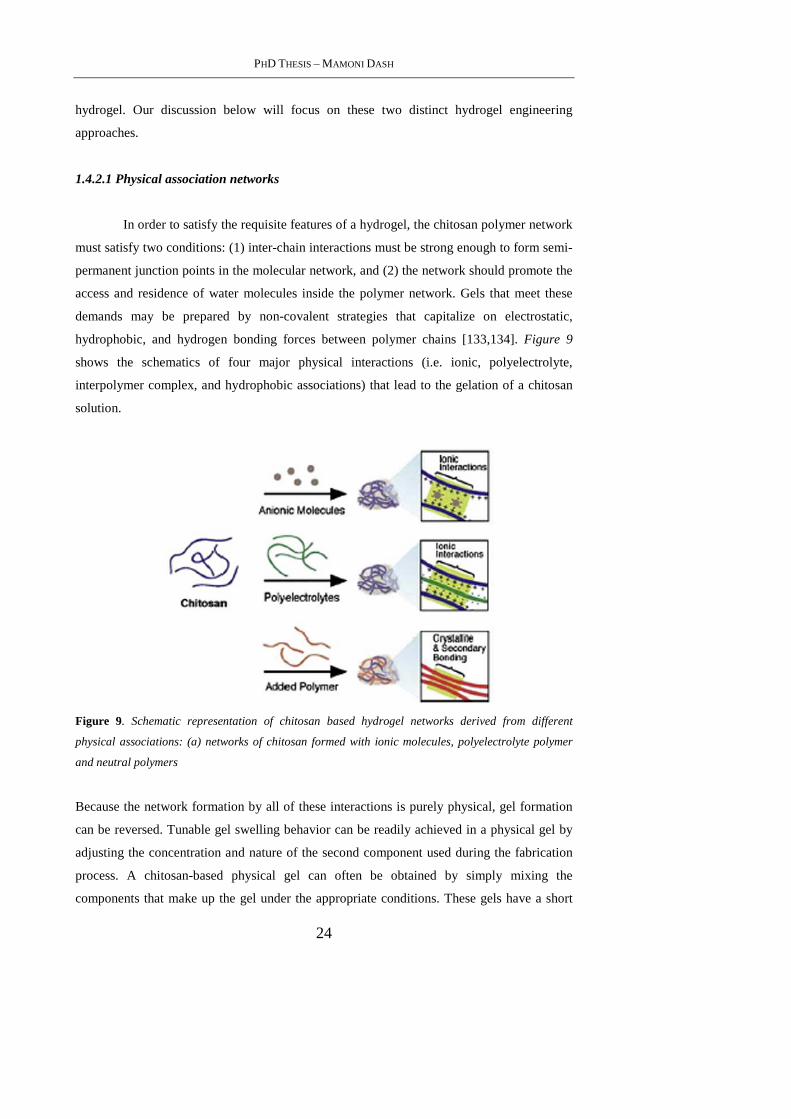
PHD THESIS – MAMONI DASH
24
hydrogel. Our discussion below will focus on these two distinct hydrogel engineering
approaches.
1.4.2.1 Physical association networks
In order to satisfy the requisite features of a hydrogel, the chitosan polymer network
must satisfy two conditions: (1) inter-chain interactions must be strong enough to form semi-
permanent junction points in the molecular network, and (2) the network should promote the
access and residence of water molecules inside the polymer network. Gels that meet these
demands may be prepared by non-covalent strategies that capitalize on electrostatic,
hydrophobic, and hydrogen bonding forces between polymer chains [133,134]. Figure 9
shows the schematics of four major physical interactions (i.e. ionic, polyelectrolyte,
interpolymer complex, and hydrophobic associations) that lead to the gelation of a chitosan
solution.
Figure 9. Schematic representation of chitosan based hydrogel networks derived from different
physical associations: (a) networks of chitosan formed with ionic molecules, polyelectrolyte polymer
and neutral polymers
Because the network formation by all of these interactions is purely physical, gel formation
can be reversed. Tunable gel swelling behavior can be readily achieved in a physical gel by
adjusting the concentration and nature of the second component used during the fabrication
process. A chitosan-based physical gel can often be obtained by simply mixing the
components that make up the gel under the appropriate conditions. These gels have a short
CHAPTER 1 – CHITOSAN-A VERSATILE MATERIAL FOR REGENERATIVE MEDICINE APPLICATIONS
25
life time in physiological media, ranging from a few days to a month. Therefore, physical
gels are good for short-term drug release applications. Because the gelation does not require
any toxic covalent linker molecules, it is always safe for clinical applications. However, their
widespread application is limited due to the weak mechanical strength and uncontrolled
dissolution [135].
1.4.2.1.1 Ionic complexes
Thanks to the cationic amino groups of chitosan, ionic interactions can occur
between chitosan and negatively charged molecules and anions. Ionic complexation of mixed
charge systems can be formed between chitosan and small anionic molecules, such as
sulfates, citrates, and phosphates [136,137] or anions of metals like Pt (II), Pd (II), and Mo
(VI) [138,139]. These interactions can yield hydrogels with varying material properties that
depend upon the charge density and size of the anionic agents, as well as the degree of
deacetylation and concentration of the chitosan polymer.
Both anions and small molecules bind chitosan via its protonated amino groups, but
metal ions form coordinate–covalent bonds with the polymer instead of electrostatic
interactions [138,139]. Ionic complexation can be accompanied by other secondary
interchain interactions including hydrogen bonding between chitosan's hydroxyl groups and
the ionic molecules, or interactions between deacetylated chitosan chains after neutralization
of their cationic charge [138,140]. These interactions can enhance the physical properties of
the hydrogel, and can be modulated to express unique material properties, such as pH
sensitivity.
1.4.2.1.2 Polyelectrolyte complexes (PEC’s)
While polyelectrolytes form electrostatic interactions with chitosan, they are
different from the ions or ionic molecules used in ionic complexation in that they are larger
molecules with a broad molecular weight range, such as polysaccharides, proteins and
synthetic polymers. The associations between the chitosan polymer and polyelectrolytes are
stronger than other secondary binding interactions like hydrogen bonding or van der Waals
interactions. The advantages of this type of complex are significant. They are complexed
without the use of organic precursors, catalysts, or reactive agents, alleviating the concern
PHD THESIS – MAMONI DASH
26
about safety in the body or cross-reactions with a therapeutic payload. In addition, because
PEC’s consist of only chitosan and the polyelectrolyte, their complexation is straightforward
and reversible. Chitosan-based PEC networks have been produced by anionic
macromolecules like DNA, anionic polysaccharides (e.g. alginate, GAGs (chondroitin
sulfate, hyaluronic acid, or heparin), carboxymethyl cellulose, pectin, dextran sulfate,
xanthan, etc.), proteins (e.g. gelatin, albumin, fibroin, keratin, and collagen) and anionic
synthetic polymers (e.g. polyacrylic acid). The stability of these compounds is dependent on
charge density, solvent, ionic strength, pH, and temperature [141,142]. The choice of the
anionic molecule for PEC formation is highly dependent upon its charge under physiological
conditions because the pH of the hydrogel environment modulates ionic interactions and,
subsequently, PEC hydrogel properties. If the electrostatic interactions of the polymer are
strong enough, the physical associations between the polymers at physiological pH can be
maintained.
1.4.2.1.3 Physical mixtures and secondary bonding
In addition to the specific physical interactions described, hydrogels can be formed
by polymer blends between chitosan and other water-soluble nonionic polymers, such as
Poly(vinly alcohol) (PVA). These polymer mixtures form junction points in the form of
crystallites and interpolymer complexation after lyophilization or after a series of freeze–
thaw cycles [133,143]. The chain–chain interactions act as crosslinking sites of the hydrogel.
In the case of chitosan–PVA polymer blends, increasing the chitosan content negatively
affects the formation of PVA crystallites, leading to the formation of hydrogels with less
ordered structures. Recently, a new hydrogel consisting of a polymer blend of chitosan and
polyethylenimine (PEI) was prepared [144]. PEI is a polycationic material that has been
extensively used as a gene transfection agent [145]. By mixing the polymer with chitosan, a
3D hydrogel was formed within 5 min that was stable under cell culture conditions and could
support the growth of primary human fetal skeletal cells. Ladet et al. demonstrated the
preparation of a hydrogel using a hydro-alcohol method of gel formation that relied upon the
neutralization of chitosan's amino groups using a sodium hydroxide solution [146]. This
prevented ionic repulsion between the polymer chains, allowing for the formation of
hydrogen bonds, hydrophobic interactions, and chitosan crystallites. Using this technique,
hydrogels on the order of cubic centimeters could be prepared. Macroscopic shrinkage of the
hydrogel during neutralization and gel depletion with the increase in the concentration of
neutralizing agent was observed (figure 10). Interestingly, an interrupted gelation method
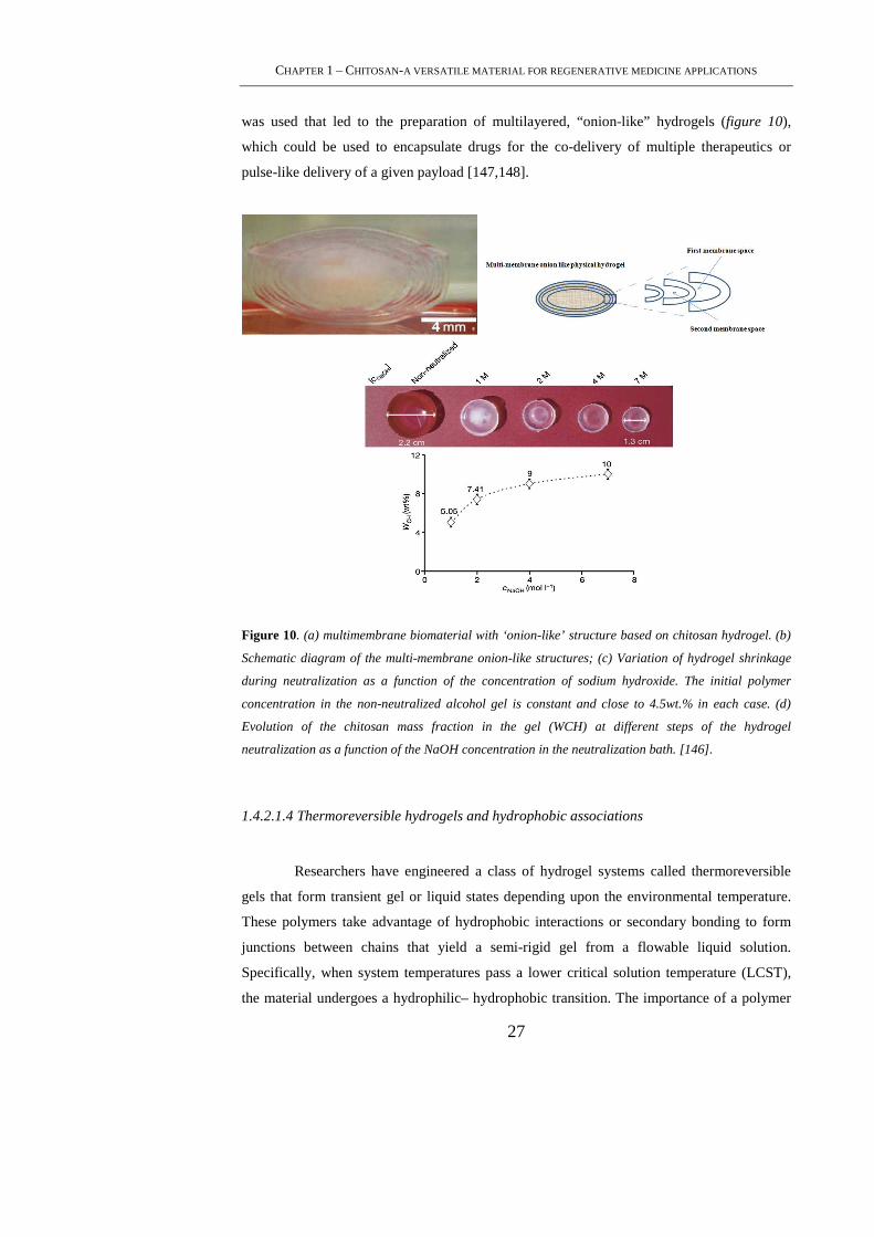
CHAPTER 1 – CHITOSAN-A VERSATILE MATERIAL FOR REGENERATIVE MEDICINE APPLICATIONS
27
was used that led to the preparation of multilayered, “onion-like” hydrogels (figure 10),
which could be used to encapsulate drugs for the co-delivery of multiple therapeutics or
pulse-like delivery of a given payload [147,148].
Figure 10. (a) multimembrane biomaterial with ‘onion-like’ structure based on chitosan hydrogel. (b)
Schematic diagram of the multi-membrane onion-like structures; (c) Variation of hydrogel shrinkage
during neutralization as a function of the concentration of sodium hydroxide. The initial polymer
concentration in the non-neutralized alcohol gel is constant and close to 4.5wt.% in each case. (d)
Evolution of the chitosan mass fraction in the gel (WCH) at different steps of the hydrogel
neutralization as a function of the NaOH concentration in the neutralization bath. [146].
1.4.2.1.4 Thermoreversible hydrogels and hydrophobic associations
Researchers have engineered a class of hydrogel systems called thermoreversible
gels that form transient gel or liquid states depending upon the environmental temperature.
These polymers take advantage of hydrophobic interactions or secondary bonding to form
junctions between chains that yield a semi-rigid gel from a flowable liquid solution.
Specifically, when system temperatures pass a lower critical solution temperature (LCST),
the material undergoes a hydrophilic– hydrophobic transition. The importance of a polymer
PHD THESIS – MAMONI DASH
28
solution that has a low viscosity at room temperature, but forms a gel above a LCST is
significant for its use in biomedical applications. These materials can be injected into the
body as a liquid, forming a gel in situ where the body temperature is above the LCST,
offering the potential to serve as carrier matrices for a wide range of biomedical and
pharmaceutical applications [149,150]. These injectable, gelling systems can be introduced
into the body without the need for invasive surgeries, and deliver the bioactive agents to a
defect site without significant negative effects (local heating, use of organic solvents,
formation of toxic byproducts, etc.). Hydrogels prepared by aggregation of chitosan-based
co-polymers or by neutralization with polyol salts show promising thermoreversible gelation
properties in aqueous media [151–155]. One such engineering strategy used the temperature-
sensitive behavior of a physical mixture of glycerol phosphate disodium salt (GP) and
chitosan. The phosphates of the GP salt are believed to neutralize the ammonium groups of
chitosan, allowing increased hydrophobic and hydrogen bonding between the chitosan chains
at elevated temperatures. The mixture remains a clear liquid at room temperature and gels at
37 °C [155]. The chitosan/GP gel showed promise as a biotherapeutic system capable of
delivering a bioactive bone protein (an osteogenic mixture of TGF β family members), and
as a cell matrix whereby chondrocytes were implanted in vivo and showed normal cartilage
formation over 3 weeks.
1.4.2.2 Crosslinked networks
While physically bonded hydrogels have the advantage of gel formation without the
use of cross-linking entities, they have limitations. It is also difficult to precisely control the
physical gel pore size, chemical functionalization, and degradation or dissolution, leading to
inconsistent performance in vivo. Alternatively, robust chitosan hydrogels can be produced
using irreversible networks. Polymeric chains of these hydrogels are covalently bonded
together either by using small cross-linker molecules, secondary polymerizations, or
irradiation chemistry. Most of these linker molecules react with the primary amines of
chitosan and form irreversible inter- or intramolecular bridges among the chitosan chains.
Covalently cross-linked hydrogels are also obtained by attaching photo-reactive or enzyme-
sensitive molecules on the chitosan, followed by their subsequent exposure to UV or
sensitive enzymes, respectively. The properties of cross-linked hydrogels depend mainly on
their crosslinking density and the ratio of moles of cross-linker molecules to the moles of
polymer repeating units [156]. The following sections describe the different ways of making
irreversible chitosan hydrogels.
CHAPTER 1 – CHITOSAN-A VERSATILE MATERIAL FOR REGENERATIVE MEDICINE APPLICATIONS
29
1.4.2.2.1 Chemical crosslinking
Chemical cross-linking is a straight forward method to produce permanent hydrogel
networks using covalent bonding between polymer chains. Cross-linked chitosan networks
can be prepared using the available –NH2 and –OH chemical handles and cross-linkers that
can form a number of linkage chemistries, including amine carboxylic acid bonding and
Schiff base formation [157-159]. Specifically, these networks can be formed by using small
molecule cross-linkers, polymer–polymer reactions between activated functional groups, as
well as photosensitive agents or enzyme-catalyzed reactions.
The new cross-linking agent, genipin, is a naturally derived chemical from the
gardenia that has been shown to be one such biocompatible cross-linking agent [160].
Genipin has been reported to bind biological tissues [161] and biopolymers, such as chitosan
and gelatin, leading to covalent coupling. It works as an effective cross-linking agent for
polymers containing amino groups and is much less cytotoxic than glutaraldehyde [162]. In
addition, genipin cross-linked chitosan membranes exhibit a slower degradation rate than
their glutaraldehyde crosslinked counterpart [163]. Use of genipin also showed extended
drug release by chitosan hydrogels cross-linked in situ [152,164]. Even though genipin
shows good biocompatibility, it is still liable to negatively interact with encapsulated drugs,
an unavoidable problem for gelation in the presence of a therapeutic [165]. A thermo-
sensitive, chitosan-pluronic hydrogel was also produced by UV photo-cross-linking [166].
The chitosan and pluronic groups were functionalized with photosensitive acrylate groups
that were cross-linked by UV exposure. The resultant polymers could then form a physical
network at temperatures above the LCST. The hydrogel showed the sustained release of
encapsulated human growth hormone (hGH) and plasmid DNA, demonstrating its potential
application for different types of drugs [166,167].
1.4.2.2.2 Interpenetrating networks (IPN’s)
Entangled polymer networks can be further strengthened by interlacing secondary
polymers within the cross-linked networks. Here, a cross-linked chitosan network is allowed
to swell in an aqueous solution of polymer monomers. These monomers are then
polymerized, forming a physically entangled polymer mesh called an interpenetrating
network. There are also semi-IPNs where only one of the polymer networks is cross-linked,
while the second polymer remains in its linear state. If the second polymer is also cross-

PHD THESIS – MAMONI DASH
30
linked, a full-IPN is formed. There are several chitosan-based semi-IPNs (prepared with
polyether [168,169], silk [170], PEO[171], and PVP [172] and full-IPNs (prepared with
PNIPAM [173]). This technique allows for the specific selection of polymers that can
complement the deficiencies of one another. For instance, a hydrophilic polymer can be
chosen to enhance the structural characteristics of the hydrogel, while a biocompatible
polymer may limit the immunological response. Although the cross-linking density, hydrogel
porosity, and gel stiffness can be adjusted in IPN-based hydrogels according to the target
application, they have difficulty encapsulating a wide variety of therapeutic agents,
especially sensitive biomolecules. In addition, IPN preparation requires the use of toxic
agents to initiate or catalyze the polymerization or to catalyze the cross-linking. Complete
removal of these materials from the hydrogel is challenging, making the clinical application
problematic.
1.4.2.3 Drug loading in chitosan hydrogels
The drug loading in a hydrogel depends upon both the physical and chemical
properties of the gel as well as the therapeutic itself. In fact, the choice of hydrogel materials,
network conformation, and drug loading mechanism must be made to complement the
properties of the drug (e.g. hydrophobilicity, charge) and its mechanism of action (sustained
drug release versus rapid, high exposure). Three major approaches to drug loading can be
summarized as : diffusion, entrapment, and tethering [174-178]. Each method bears specific
advantages and disadvantages and should be selected after taking into consideration the
hydrogel network used as well as the nature of the drug. The easiest drug loading method is
to place the fully formed hydrogel into medium saturated with the therapeutic [179,180].
Depending upon the porosity of the hydrogel, the size of the drug, and the chemical
properties of each, the drug will slowly diffuse into the gel. When placed in vivo, the drug
will then freely diffuse back out of the hydrogel into the neighboring tissue. This approach is
effective for loading small molecules, but larger therapeutics peptides and proteins in
particular are not readily able to migrate through the small pores of the hydrogel [165]. In
addition, this drug loading process can take long time. In the case of larger drugs and
bioligands, the payload must be entrapped during the gelation process. Here, the drug is
mixed with the polymer solution, and the cross-linking or complexation agent is added. It is
important to consider the chemistry of the drug molecule to prevent unwanted cross-linking
or deactivation of the therapeutic during gelation. Both diffusion and entrapment allow for
free movement of the therapeutic out of the hydrogel network. This can lead to an initial
CHAPTER 1 – CHITOSAN-A VERSATILE MATERIAL FOR REGENERATIVE MEDICINE APPLICATIONS
31
burst release after implantation of the hydrogel in vivo due to the concentration gradient
formed between the gel and the surrounding environment. In order to limit the loss of the
therapeutic reserve (and the risk of toxic exposure), drugs can be covalently or physically
linked to the polymer chains prior to gelation. This tethering method limits tissue exposure to
the agent to only when the hydrogel breaks down or the molecular tether is broken [181].
Linkages between the drug and polymer that are susceptible to environmental enzymes have
been used to control the speed and timing of release. Drug loading is also complicated by
molecules that have the opposite hydrophilicity or the same charge as the constituent
polymer. For instance, hydrophobic molecules like paclitaxel must be complexed with
amphiphilic additives before the hydrogel and payload will blend in solution [183, 184]. This
has been accomplished by binding the drug to albumin (Abraxane) or by mixing it in an
aqueous citric acid/glyceryl monooleate solution prior to hydrogel loading [184].
Therapeutics have also been loaded into small secondary release vehicles (e.g.
microparticles, microgels, liposomes, and micelles) prior to hydrogel encapsulation [185,
186].
1.4.2.4 Drug release from chitosan hydrogels
Release of loaded therapeutics from a hydrogel can occur by one of three different
modes: diffusion, chemical/environmental stimulation, and enzyme-specific stimulation
[187]. Diffusion is regulated by movement through the polymer matrix or by bulk erosion of
the hydrogel as it breaks down in vivo. Environmentally responsive hydrogels are gels that
swell in response to external cues like pH and temperature and effectively open their pores
for enhanced diffusion of the entrapped therapeutic under predetermined conditions[165].
This type of controlled release can be used to limit drug release outside of the effective range
of the diseased tissue. Environmental cues are specific to limited regions within the body, but
better specificity has also been widely investigated with new release mechanisms that release
a drug payload only when triggered by local enzymatic cues. These biochemically stimulated
responses occur by tethering drugs to the hydrogel via labile domains that are susceptible to
matrix remodeling enzymes or using polymers that are targeted by enzymes [188]. This
method has received the least amount of attention, but offers selective, sustained release
mechanisms that are beginning to receive attention from chitosan hydrogel engineers.
PHD THESIS – MAMONI DASH
32
1.5. Applications
1.5.1 Chitosan for Tissue Engineering Applications
Tissue engineering is an interdisciplinary field that applies the principles and
methods of engineering and the life sciences toward the fundamental understanding of
structural and functional relationships in normal and pathological tissue and the development
of biological substitutes to restore, maintain, or improve function [189]. It involves the in
vitro seeding and growing of relevant cells onto a scaffold. The scaffold therefore is a very
important component for tissue engineering. Several requirements have been identified as
crucial for the production of tissue engineering scaffolds: 1) the scaffold should possess
interconnecting pores of appropriate scale to favor tissue integration and vascularization, 2)
be made from material with controlled biodegradability or bioresorbability so that tissue will
eventually replace the scaffold, 3) have appropriate surface chemistry to favor cellular
attachment, differentiation and proliferation, 4) possess adequate mechanical properties to
match the intended site of implantation and handling, 5) should not induce any adverse
response and, 6) be easily fabricated into a variety of shapes and sizes [190]. The versatility
of chitosan offer a wide range of applications since they are biodegradable, non-toxic and
can be formulated in a variety of forms including powders, gels and films for applications.
They can also provide controlled release of growth factors and extracellular matrix
components. To improve the adherent ability for seeding cells, chitosan allow for a wide
range of molecules to be modified. With these promising features, they are considered as a
very interesting biomaterial for use in cell transplantation and tissue regeneration. This
technology has been used to create various tissue analogs including cartilage, bone, liver, and
nerve in the past decades.
1.5.1.1 Chitosan in bone tissue engineering
Chitosan has been extensively used in bone tissue engineering since it was shown to
promote growth and mineral rich matrix deposition by osteoblasts in culture [191]. Also
chitosan is biocompatible (minimizes additional local inflammation), biodegradable, and can
be molded into porous structures (allows osteoconduction) [192]. Several studies have
focused on the use of chitosan–calcium phosphate (CP) composites for this purpose
[193,194]. A 3D macroporous CP bioceramic embedded with porous chitosan sponges is
developed by Zang et al. [195]. In this scaffold, a nested chitosan sponge enhanced the
CHAPTER 1 – CHITOSAN-A VERSATILE MATERIAL FOR REGENERATIVE MEDICINE APPLICATIONS
33
mechanical strength of the ceramic phase via matrix reinforcement and preserved the
osteoblast phenotype [196]. Macroporous chitosan scaffolds incorporating hydroxyapatite
(HA) or CP glass with an interconnected porosity of approximately 100 mm have been
synthesized [196]. Overall composites of chitosan–CP appear to have a promising clinical
application in the future [197]. The issue of mechanical resistance of chitosan-based
composites was addressed by Hu et al. [198], who reported a chitosan–HA multilayer
nanocomposite with high strength and bending modulus rendering the material suitable for
possible application for internal fixation of long bone fractures. A macroporous chitosan-
gel/b-TCP composite scaffold for bone tissue engineering using freeze-drying process was
developed [199]. This study investigated the effects of concentration of composite
suspension and the freezing temperature on the ability to resist compression by the scaffold
[200]. Chitosan was used as an adjuvant with bone cements to increase their injectability
while keeping the chemico-physical properties suitable for surgical use (e.g. setting time and
mechanical properties). The rationale of using chitosan for this purpose is based on the
property that chitosan solutions gel in response to a pH change from slightly acidic to
physiological; in fact, the chitosan–CP composites address the need to develop bone fillers
that set in response to physiological conditions, but not while mixing the components in
vitro. Likewise, when chitosan is added to calcium phosphate cements (CPC), octocalcium
phosphate is obtained; a material that is shown to improve injectability and strength [200].
Many of these chitosan gel composites are proposed mainly for non load bearing bony
defects [201]. Xu et al. studied the feasibility of creating macropores in CPC using chitosan
and/or absorbable mesh. A synergistic effect of adding chitosan and bioabsorbable mesh to
CPC was seen. This injectable, bioabsorbable composite material possessed interconnected
macropores (osteoconductive) and provided strength to the implant during tissue
regeneration [202]. The intramolecular hydrogen bonds of chitosan provide interacting
macromolecules with a good resistance to heat. Zhao et al. used phase separation technique
to fabricate biomimetic HA/chitosan–gelatin network composites in the form of 3D-porous
scaffolds and they showed improved adhesion, proliferation and expression of rat calvaria
osteoblasts on these highly porous scaffolds [203]. Kim et al. showed the application of this
property through composites of chitosan with poly methyl-methacrylate (PMMA). This
specially developed composite material exhibited lower exothermic curing temperatures and
possessed higher inter-connected porosity with a pore size suitable for osteoconduction with
better anchorage to the surrounding bone. It was observed that the pore size of this composite
material increased with time due to biodegradation of the chitosan [204]. Also, chitosan has
PHD THESIS – MAMONI DASH
34
been used to modify the surface properties of prosthetic materials for the attachment of
osteoblasts [205, 206].
In another recent work by Zhao et al., scaffold with calcium phosphate cement
(CPC) and chitosan fibres were prepared and studies. It was found that human umbilical cord
mesenchymal stem cells (hUCMSCs) can be harvested without an invasive procedure
required for the commonly studied bone marrow mesenchymal cells (MSCs). The objectives
of this study were to develop CPC scaffolds with improved resistance to fatigue and fracture,
and to investigate hUCMSC delivery for bone tissue engineering. In fast fracture, CPC with
15% chitosan and 20% polyglactin fibers (CPC–chitosan–fiber scaffold) had flexural
strength of 26 MPa, higher than 10 MPa for CPC control (p < 0.05). In cyclic loading, CPC–
chitosan–fiber specimens that survived 2 * 106 cycles had the maximum stress of 10 MPa,
compared to 5 MPa of CPC control. CPC–chitosan–fiber specimens that failed after multiple
cycles had a mean stress-to-failure of 9 MPa, compared to 5.8 MPa for CPC control (p <
0.05).
1.5.1.2 Chitosan in cartilage tissue engineering
In cartilage repair, the choice of biomaterial is very critical for the success of tissue
engineering approaches [208]. The ideal cell-carrier substance should mimic the natural
environment in the articular cartilage matrix. It has been shown that cartilage-specific
extracellular matrix (ECM) components such as type II collagen and GAGs play a critical
role in regulating expression of the chondrocytic phenotype and in supporting
chondrogenesis in vitro as well as in vivo [209,210]. Three-dimensional (3D) scaffolds are
essential for the development of engineered articular cartilage. Ideal scaffolds are designed
to be biocompatible, bioabsorbable and exhibit predictable porosity and degradation rate.
They provide a framework that facilitates new tissue in growth; moreover, mechanical
characteristics are matched to those of the native tissue increasing the chances that the
reparative process will be compatible with the host’s tissue physiology [211,212]. Chitosan
has been used as a scaffolding material in articular cartilage engineering [213,214], due to its
structural similarity with various GAGs found in articular cartilage. This is of high
importance because GAGs are considered to play a pivotal role in modulating chondrocyte
morphology, differentiation, and function. Iwasaki et al. [215] reported an alginate-based
chitosan hybrid polymer fibers which showed increased cell attachment and proliferation in
vitro compared to alginate. These hybrid polymer fibers showed increased tensile strength,
implying a possible use in developing a 3D load bearing scaffold for cartilage regeneration
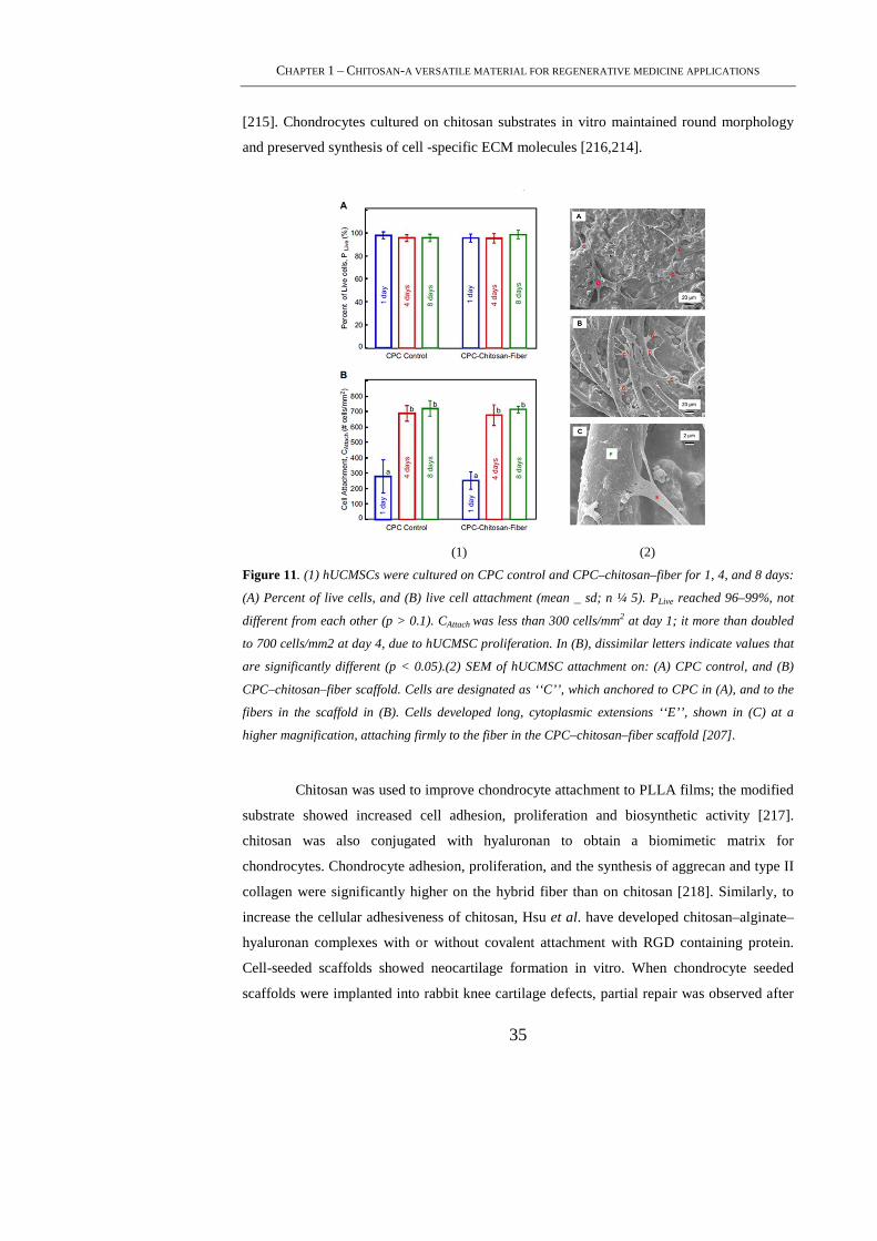
CHAPTER 1 – CHITOSAN-A VERSATILE MATERIAL FOR REGENERATIVE MEDICINE APPLICATIONS
35
[215]. Chondrocytes cultured on chitosan substrates in vitro maintained round morphology
and preserved synthesis of cell -specific ECM molecules [216,214].
(1) (2)
Figure 11. (1) hUCMSCs were cultured on CPC control and CPC–chitosan–fiber for 1, 4, and 8 days:
(A) Percent of live cells, and (B) live cell attachment (mean _ sd; n ¼ 5). PLive reached 96–99%, not
different from each other (p > 0.1). CAttach was less than 300 cells/mm2 at day 1; it more than doubled
to 700 cells/mm2 at day 4, due to hUCMSC proliferation. In (B), dissimilar letters indicate values that
are significantly different (p < 0.05).(2) SEM of hUCMSC attachment on: (A) CPC control, and (B)
CPC–chitosan–fiber scaffold. Cells are designated as ‘‘C’’, which anchored to CPC in (A), and to the
fibers in the scaffold in (B). Cells developed long, cytoplasmic extensions ‘‘E’’, shown in (C) at a
higher magnification, attaching firmly to the fiber in the CPC–chitosan–fiber scaffold [207].
Chitosan was used to improve chondrocyte attachment to PLLA films; the modified
substrate showed increased cell adhesion, proliferation and biosynthetic activity [217].
chitosan was also conjugated with hyaluronan to obtain a biomimetic matrix for
chondrocytes. Chondrocyte adhesion, proliferation, and the synthesis of aggrecan and type II
collagen were significantly higher on the hybrid fiber than on chitosan [218]. Similarly, to
increase the cellular adhesiveness of chitosan, Hsu et al. have developed chitosan–alginate–
hyaluronan complexes with or without covalent attachment with RGD containing protein.
Cell-seeded scaffolds showed neocartilage formation in vitro. When chondrocyte seeded
scaffolds were implanted into rabbit knee cartilage defects, partial repair was observed after

PHD THESIS – MAMONI DASH
36
1 month both in presence or absence of RGD indicating potential of this composite material
for cartilage regeneration [219].
Chitosan-based scaffolds can deliver growth factors in a controlled fashion to
promote the in growth and biosynthetic ability of chondrocytes. Lee et al. [220] reported
porous collagen/chitosan/GAG scaffolds loaded with TGF-b1. This scaffold exhibited
controlled release of TG F-b1 and promoted cartilage regeneration. Moreover, addition of
chitosan to the collagen scaffold was seen to improve mechanical properties [220] and
stability of the collagen network by inhibiting the action of collagenases [221]. Kim et al.
[222] used a porous freeze-dried chitosan scaffold incorporating TGF-b1-containing
microspheres, for the treatment of cartilage defects. TGF-b1 was released in a sustained
fashion, and promoted chondrocyte proliferation and matrix synthesis. In a similar trial, Lu et
al. studied the effect of intraarticular injection of chitosan on regeneration of articular
cartilage. An increase in epiphyseal cartilage in the tibial and femoral joints was seen with an
activation of chondrocyte proliferation. Similarly, an intra-articular fibrous tissue was
observed for the 6 weeks of the experiment, together with residual injected chitosan [223].
A noteworthy accomplishment was achieved by Buschmann et al. who showed that
microfractured ovine defects are repaired with more hyaline cartilage when the defect is
treated with in situ-solidified implants of chitosan–GP mixed with autologous whole blood,
compared to microfracture alone in an ovine model at 6 months [224]. Since bleeding has
been identified as an initiating event in post-surgical repair, they hypothesized that
microfracture-based repair could be improved by stabilizing the clot formed in the lesion
with chitosan that is thrombogenic and actively stimulates the wound repair process.
Furthermore, these chitosan– GP/blood clots are adhesive and contract much less than whole
blood clots, thereby maintaining a voluminous scaffold [224]. Chitosan–GP/blood implants
were applied to marrow-stimulated chondral defects in rabbit cartilage repair models [225],
where they induced greater fill of chondral defects with repair tissue compared to marrow-
stimulation alone [224] and, in addition, produced a more cellular and hyaline repair
cartilage well integrated with a porous subchondral bone structure [224-226]
In a recent work by Haoya et al.[227] chitosan hydrogel in the form of a scaffold
was prepared for chondrocytes that would act to reconstruct tissue-engineered cartilage and
repair articular cartilage defects in the sheep model. In this study, temperature-responsive
chitosan hydrogels were prepared by combining chitosan, b-sodium glycerophosphate (GP)
and hydroxyethyl cellulose (HEC). Tissue-engineered cartilage reconstructions were made in
vitro by mixing sheep chondrocytes with a chitosan hydrogel. Cell survival and matrix
accumulation were analyzed after 3 weeks in culture (figure 12(a)). To collect data for in
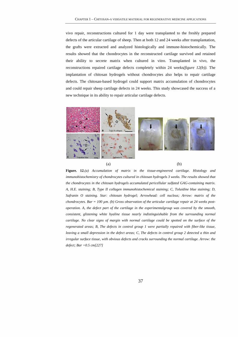
CHAPTER 1 – CHITOSAN-A VERSATILE MATERIAL FOR REGENERATIVE MEDICINE APPLICATIONS
37
vivo repair, reconstructions cultured for 1 day were transplanted to the freshly prepared
defects of the articular cartilage of sheep. Then at both 12 and 24 weeks after transplantation,
the grafts were extracted and analyzed histologically and immune-histochemically. The
results showed that the chondrocytes in the reconstructed cartilage survived and retained
their ability to secrete matrix when cultured in vitro. Transplanted in vivo, the
reconstructions repaired cartilage defects completely within 24 weeks(figure 12(b)). The
implantation of chitosan hydrogels without chondrocytes also helps to repair cartilage
defects. The chitosan-based hydrogel could support matrix accumulation of chondrocytes
and could repair sheep cartilage defects in 24 weeks. This study showcased the success of a
new technique in its ability to repair articular cartilage defects.
(a) (b)
Figure. 12.(a) Accumulation of matrix in the tissue-engineered cartilage. Histology and
immunohistochemistry of chondrocytes cultured in chitosan hydrogels 3 weeks. The results showed that
the chondrocytes in the chitosan hydrogels accumulated pericellular sulfated GAG-containing matrix.
A, H.E. staining; B, Type II collagen immunohistochemical staining; C, Toluidine blue staining; D,
Safranin O staining. Star: chitosan hydrogel; Arrowhead: cell nucleus; Arrow: matrix of the
chondrocytes. Bar = 100 µm. (b) Gross observation of the articular cartilage repair at 24 weeks post-
operation. A, the defect part of the cartilage in the experimentalgroup was covered by the smooth,
consistent, glistening white hyaline tissue nearly indistinguishable from the surrounding normal
cartilage. No clear signs of margin with normal cartilage could be spotted on the surface of the
regenerated areas; B, The defects in control group 1 were partially repaired with fiber-like tissue,
leaving a small depression in the defect areas; C, The defects in control group 2 detected a thin and
irregular surface tissue, with obvious defects and cracks surrounding the normal cartilage. Arrow: the
defect; Bar =0.5 cm[227]

PHD THESIS – MAMONI DASH
38
1.5.1.3 Chitosan in liver tissue engineering
Insufficient donor organs for orthotopic liver transplantation worldwide have
urgently increased the requirement for new therapies for acute and chronic liver disease
[228]. Bioartificial liver (BAL) is a promising application of tissue engineering for the
treatment of fulminant hepatic failure (FHF). One of the important issues for BAL devices is
the proper choice of cell sources, such as primary hepatocytes, hepatic cell lines, and liver
stem cells. The primary hepatocyte of these cells represents the most direct approach to BAL
devices. BAL devices require a suitable ECM for hepatocyte culture because hepatocytes are
anchorage dependent cells and are highly sensitive to the ECM milieu for the maintenance of
their viability and differentiated functions [229-231]. Chitosan as a promising biomaterial
can be applied in liver tissue engineering due to its various properties. One of the reasons for
selecting chitosan as a scaffold for hepatocytes culture is that its structure is similar to
GAGs, which are components of the liver ECM prepared chitosan/ collagen matrix (CCM)
by cross-linking agent EDC in NHS buffer system[232-235]. The EDC cross-linked CCM
showed moderate mechanical strength, good hepatocyte compatibility as well as excellent
blood compatibility. On the other hand, implantable bioartificial liver (IBL) can restore,
maintain or improve liver functions or offer the possibility of permanent liver replacement.
Unlike the general approach for bioartificial skin, bone and cartilage, development of IBL
has extreme difficulties. Appropriate design of the complex architecture, as well as the anti-
thrombogenic extracellular component, are necessary for developing this blood-contacting
device, because thrombus formation can lead to occlusion and decrease membrane efficiency
[236]. Wang et al. showed a superior blood compatibility through chitosan/collagen / heparin
matrix in implantable bioartificial liver (IBL) applications [237].
Another strategy in liver tissue engineering focuses on the ability of highly
concentrated, multivalent galactose residues to bind to the asialoglycoprotein receptor
(ASGPR) expressed on the surface of hepatocytes. Typical cell–matrix interaction is
mediated by adhesion receptor such as integrin which specifically binds RGD sequence
[238]. The ASGPR was the first reported mammalian lectin, or carbohydrate-binding protein.
It was discovered in the mid-1960s by Ashwell et al. in their studies of the metabolism of
plasma glycoproteins in mammals [239-240]. Since then, hepatic ASGPR has been a
classical system for studying receptor-mediated endocytosis. Chung et al. suggested a
potential ability to improve hepatocyte attachment to alginate (AL)/GC scaffolds for short-
term culture[241]. In study by Kim & Seo, they further showed enhanced hepatocyte
functions in AL/GC scaffolds for long periods. That is, hepatocyte cultured in AL/GC

CHAPTER 1 – CHITOSAN-A VERSATILE MATERIAL FOR REGENERATIVE MEDICINE APPLICATIONS
39
scaffolds could enhance the functions through its spheroid formation (figure 13) in co-culture
condition with fibroblast [228]. Li et al. conjugated fructose onto the porous chitosan
scaffold by the reaction between amino and aldehyde group. Fructose is also known as a
specific ligand of ASGPR in hepatocyte. They showed that the chitosan surface modified
with fructose induced the formation of cellular aggregates with enhancing liver specific
metabolic activities and cell density to a satisfactory level [233-234].
Figure 13. Phase-contrast micrographs of hepatocytes within the AL (A) and AL/GC (B) scaffold
stained with MTT and comparisons of liver-specific albumin secretion function [228].
4.1.1.3 Chitosan in nerve tissue engineering
More than any other form of trauma, nerve injuries complicate successful
rehabilitation since it is difficult for mature neurons (like many other cells in the body) to
replicate, as they do not undergo cell division. Once the nervous system is impaired, its
recovery is difficult and malfunction of other parts of the body occurs [242]. The repair of
nerve lesions has been attempted in many different ways, which have in common the goal of
directing the regenerating nerve fibers into the proper endoneurial tubes. The strategies
developed for nerve repair can be classified into two categories: (1) bridging, which includes
grafting and tubulization techniques, (2) end-to-end suturing of the nerve stumps. The former
technique has been shown to be more effective, as it avoids tension across the repair site
[243]. A wide variety of materials have been suggested for the production of artificial tubes
for nerve repair, including biocompatible, non-degradable and degradable materials. A
PHD THESIS – MAMONI DASH
40
variety of artificial tubes have been used to repair nerve injuries, but the artificial tubes do
not have enough internal surface area for nerve fibers and Schwann cells (SCs) to cohere
[236]. Thus, artificial tubes to bridge large defects in nerve repair should contain a
biodegradable matrix, which can provide an optimal structural, cellular, and molecular
framework for SCs and neurite migration across a nerve gap. Chitosan has been studied as a
candidate material for nerve regeneration due to its properties such as antitumor,
antibacterial activity, biodegradability and biocompatibility. Jianchun et al. reported that
neurons cultured on the chitosan membrane can grow well and that chitosan tube can greatly
promote the repair of the peripheral nervous system [244]. Yuan et al.[245] also showed that
chitosan fibers supported the adhesion, migration and proliferation of SCs, which provide a
similar guide for regenerating axons to Büngner bands in the nervous system. Matsuda et al.
developed a new biomaterial for nerve regeneration through immobilization of laminin
peptide in molecularly aligned chitosan by covalent bonding [246]. Chávez-Delgado et al.
showed that progesterone delivered from chitosan prostheses provides better facial nerve
regenerative response of the rabbits than chitosan prostheses without progesterone [247].
Mingyu et al. showed an improved attachment, differentiation and growth on the chitosan/
poly(L-lysine) composite materials when compared to cells cultured on chitosan membranes.
The improved nerve cell affinity on the chitosan/poly(L-lysine) composite materials had
been attributed to the increased hydrophilicity by the abundant hydroxyl group and the
positive surface charge of chitosan [248]. Cheng et al. added gelatin to chitosan for
preparation of soft and elastic complex that has good nerve cell affinity. The chitosan/gelatin
composite film showed a lower modulus and a higher percentage of elongation at break
compared with chitosan film. Also, PC12 cells cultured on the composite films differentiated
more rapidly and extended longer neutites than on chitosan films [249]. Frier et al. also
developed chitin hydrogel tubes which were fabricated from chitosan solutions using
acylation chemistry and mold casting techniques for the preservation of the natural chemical
composition of chitin, and no toxic crosslinking agent was necessary for the hydrogel
preparation (figure 14). Chitin and chitosan support nerve cell adhesion and neurite
outgrowth, making these materials potential candidates for scaffolds in neural tissue
engineering [250].

CHAPTER 1 – CHITOSAN-A VERSATILE MATERIAL FOR REGENERATIVE MEDICINE APPLICATIONS
41
Figure 14. Optical microscope longitudinal view of (a) a chitin hydrogel tube and (b) a chitin gel tube
reinforced with a PLGA coils embeddedin the wall [250].
1.5.2 Drug Delivery Applications
Drug delivery has been a very active area, especially for chitosan as a carrier for
various active agents including drugs and biologics. Chitosan films are very commonly used
for this purpose, a novel inorganic–organic pH-sensitive membrane based on an
interpenetrating network utilizing inorganic silicate and organic chitosan was proposed by
Park et al. for drug delivery [251]. The membrane was evaluated for its response to pH
changes; the intended method of application. Percolation of lidocaine-HCl, sodium salicylate
and 4-acetomidophenol into this membrane was studied and found to be sensitive to the
external pH as well as the drugs’ ionic interactions with chitosan. The membrane was
proposed to also be sensitive to other stimuli such as temperature and light that may be
alternative channels for drug loading. In a similar fashion, the in-situ light initiated
polymerization of acrylic acid in the presence of chitosan was used to derive a novel
mucoadhesive membrane [252]. The interactions between the two polymers were determined
to be based on hydrogen bonding. The strong adhesive property of this membrane rendered it
suitable for transmucosal drug delivery applications. The loading and release study of
triamcinolone acetonide (TAA), a drug used to reduce inflammation in the treatment of
mouth ulcers, was subsequently reported [252]. TAA was loaded into the chitosan–PAA
membrane from solution. The drug loaded membrane was found to meet the requirements for
a transmucosal drug delivery system with drug release a function of pH and the amount of
drug loaded. Another method of generating membranes was the interaction of oxidized
glucose dialdehyde with chitosan [254]. N-alkyl groups of varying chain lengths were used
PHD THESIS – MAMONI DASH
42
to modify the hydrophobicity of these chitosan membranes. The longer the alkyl chain, the
more hydrophobic the chitosan membrane becomes and that had bearing on the drug release
rate. Using vitamin B2 as the drug model various parameters were studied, the permeation
and diffusion of B2 decreased with increasing pH 8 and when the hydrophobicity of chitosan
increased, i.e. as the alkyl chains increased in length. In vitro studies indicated no toxic
effects for this membrane system. Another example of membrane methodology is the
chitosan–gelatin drug containing films incorporating danshen, an herbal extract, without the
need for crosslinking, for delivery in the abdominal cavity [255]. Again, Hu et al. [256]
utilised the same in situ polymerization of acrylic acid in the presence of chitosan, to form
nanoparticles. The yield of nanoparticles was found to be a function of the molecular weight
of chitosan; the lower molecular weight, the better the yield of around 70%. A silk peptide
was incorporated into the nanoparticles. The release of the silk peptide occurred as an initial
burst followed by continued release for up to 10 days. The dependence of the release on pH
was noted and the authors suggested the nanospheres were useful for drug release
applications in the gastric cavity.
Cisplatin loaded chitosan microspheres were prepared using a w/o emulsion system
[257]. Variables such as chitosan concentration, cisplatin, glutaraldehyde concentration, type
of chitosan and oil were studied and found to have a significant effect on cisplatin
entrapment in chitosan microspheres. Incorporation efficiency was found to be between 28
and 29%. The type of oil used was found to affect release properties of cisplatin, which
showed an initial burst effect. Pharmacokinetics, targeting, embolization effects and
alteration of liver function using cisplatin chitosan microspheres were studied after hepatic
arterial embolization in dogs. Results showed a remarkable decrease in the number of
arterioles in liver, necrosis of nodules and hepatic cell degeneration in the embolized region.
Shiraishi et al. also prepared indomethacin loaded chitosan microspheres but by
polyelectrolyte complexation of sodium tripolyphosphate and chitosan. A pH-dependent
disintegration of the beads was observed in the in vitro study [258]. The plasma
concentrations of indomethacin after oral administration of chitosan gel beads to beagle dogs
exhibited a sustained-release pattern. Good correlation was observed between the molecular
weight of chitosan and dissolution rate constant or the mean absorption time or area under
the plasma concentration–time curve. Another study reported, the preparation of inomethacin
loaded chitosan microspheres using only aqueous solvents [259]. The influence of
formulation variables on indomethacin content in the microspheres and time for release of
indomethacin from the microspheres was also investigated.
CHAPTER 1 – CHITOSAN-A VERSATILE MATERIAL FOR REGENERATIVE MEDICINE APPLICATIONS
43
Hejazi and Amiji examined the gastric residence time of tetracycline loaded
chitosan microspheres (prepared by ionic crosslinking and precipitation method) following
their oral administration in gerbils [260]. Gastric retention studies were performed by
administering radioiodinated [125I] chitosan microsphere suspension in the nonacid-
suppressed and acid-suppressed states. At different time points, animals were sacrificed and
the radioactivity in tissues and fluids was measured with a gamma counter. The results
indicated that chitosan microspheres did not provide a longer residence time in the fasted
gerbil stomach. The tetracycline concentration profile in the stomach following
administration of microsphere formulation was similar to that of aqueous solution. Huang et
al. [261] observed that betamethasone disodium phosphate-loaded microspheres
demonstrated good drug stability (<1% hydrolysis product), high entrapment efficiency
(95%) and positive surface charge (37.5 mV). The results also indicated that yield and size of
particle was increased with increasing betamethasone amount but both zeta potential and tap
density of the particles decreased with increasing betamethasone loaded amount. The in vitro
release of betamethasone showed a dose-dependent burst followed by a slower release phase
that was proportional to the drug concentration in the concentration range between 5 and
30% (w/w) [262].
Chitosan hydrogels coupled with BMP-7 have shown the ability to enhance lesion
repair [263]. For instance, to enhance cartilage formation, chondroitin sulfate, a GAG
molecule found in cartilage, has been immobilized in chitosan hydrogels [264]. Platelet
derived growth factor has also been loaded into chitosan gels to enhance osteoinduction by
release of the growth factor as the hydrogel degraded at the defect site [265,266]. Chitosan–
alginate hydrogels loaded with BMP-2 and mesenchymal stem cells (MSCs) were shown to
induce subcutaneous bone formation [267]. Chitosan– laminin nerve guides loaded with glial
cell line-derived nerve growth factor (GDNF) enhanced both the functional and sensory
nerve recovery by releasing GDNF in the early stage of implantation [268]. Treatment with
some growth factors that have short therapeutic half-lives, such as endothelial growth factor,
require frequent administration to maintain an effective concentration. Chitosan–albumin
hydrogel microspheres have shown continuous release for over 3 weeks after subcutaneous
implantation in rats, indicating possible success in vivo [269]. Azab et al. developed a
chitosan-based hydrogel cross-linked with glutaraldehyde [270,271] and loaded with
131Inorcholesterol (131I-NC), and tested the hydrogel in a breast cancer xenograft mouse
model. This hydrogel showed a reduction in the progression rate of the tumor, and prevented
69% of tumor recurrence and metastatic spread. Importantly, there was little or no systemic
distribution of the radioisotope after hydrogel implantation.
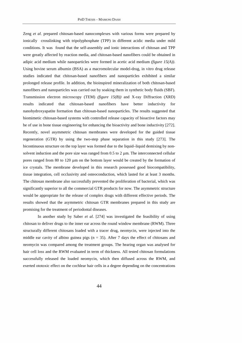
PHD THESIS – MAMONI DASH
44
Zeng et al. prepared chitosan-based nanocomplexes with various forms were prepared by
ionically crosslinking with tripolyphosphate (TPP) in different acidic media under mild
conditions. It was found that the self-assembly and ionic interactions of chitosan and TPP
were greatly affected by reaction media, and chitosan-based nanofibers could be obtained in
adipic acid medium while nanoparticles were formed in acetic acid medium (figure 15(A)).
Using bovine serum albumin (BSA) as a macromolecular model-drug, in vitro drug release
studies indicated that chitosan-based nanofibers and nanoparticles exhibited a similar
prolonged release profile. In addition, the bioinspired mineralization of both chitosan-based
nanofibers and nanoparticles was carried out by soaking them in synthetic body fluids (SBF).
Transmission electron microscopy (TEM) (figure 15(B)) and X-ray Diffraction (XRD)
results indicated that chitosan-based nanofibers have better inductivity for
nanohydroxyapatite formation than chitosan-based nanoparticles. The results suggested that
biomimetic chitosan-based systems with controlled release capacity of bioactive factors may
be of use in bone tissue engineering for enhancing the bioactivity and bone inductivity [272].
Recently, novel asymmetric chitosan membranes were developed for the guided tissue
regeneration (GTR) by using the two-step phase separation in this study [273]. The
bicontinuous structure on the top layer was formed due to the liquid–liquid demixing by non-
solvent induction and the pore size was ranged from 0.5 to 2 µm. The interconnected cellular
pores ranged from 80 to 120 µm on the bottom layer would be created by the formation of
ice crystals. The membrane developed in this research possessed good biocompatibility,
tissue integration, cell occlusivity and osteoconduction, which lasted for at least 3 months.
The chitosan membrane also successfully prevented the proliferation of bacterial, which was
significantly superior to all the commercial GTR products for now. The asymmetric structure
would be appropriate for the release of complex drugs with different effective periods. The
results showed that the asymmetric chitosan GTR membranes prepared in this study are
promising for the treatment of periodontal diseases.
In another study by Saber et al. [274] was investigated the feasibility of using
chitosan to deliver drugs to the inner ear across the round window membrane (RWM). Three
structurally different chitosans loaded with a tracer drug, neomycin, were injected into the
middle ear cavity of albino guinea pigs (n = 35). After 7 days the effect of chitosans and
neomycin was compared among the treatment groups. The hearing organ was analysed for
hair cell loss and the RWM evaluated in term of thickness. All tested chitosan formulations
successfully released the loaded neomycin, which then diffused across the RWM, and
exerted ototoxic effect on the cochlear hair cells in a degree depending on the concentrations
CHAPTER 1 – CHITOSAN-A VERSATILE MATERIAL FOR REGENERATIVE MEDICINE APPLICATIONS
45
used. Chitosans had no noxious effect on the cochlear hair cells. It is concluded that chitosan,
is safe and effective carriers for inner ear therapy.
Figure 15.(A) TEM images of Chitosan-TPP nanocomplexes formed by ionically crosslinking in (a)
adipic acid medium and (b) acetic acid medium.(B) TEM photos of (a) chitosan-TPP nanoparticles and
(b) chitosan-TPP nanofibers after soaking in SBF at 37.0 ± 0.5_C for 7 days[272].
Several studies of chitosan particles or polyelectrolytes complexes for nasal
delivery of therapeutic proteins have been done [275-278]. It has been shown that insulin-
loaded chitosan nanoparticles enhanced nasal absorption of proteins to a greater extent than
chitosan solutions [275, 278]. Powder formulations of protein-loaded chitosan nanoparticles
suitable for pulmonary delivery were prepared by spray drying [279-281]. Insulin-loaded
nanoparticles were obtained by ionic gelation of a chitosan solution with a TPP solution also
containing insulin. The nanoparticles were suspended in a solution of mannitol and lactose.
Spray-drying yielded microparticle powders with a suitable aerodynamic diameter (1-3 mm)
for alveolar deposition. The insulin-loaded chitosan nanoparticles had a good loading
capacity (65–80%) and were fully recovered from the powder formulations after contact with
an aqueous medium, and showed a fast release of insulin [281]. Yang et al. prepared an
inhalable chitosan-based powder formulation of salmon calcitonin containing mannitol (as a
cryoprotecting agent) using a spray drying process. The effect of chitosan on the
physicochemical stability of the protein was investigated with chromatographic and
PHD THESIS – MAMONI DASH
46
spectrometric techniques. The dissolution rate of the protein decreased when formulated with
chitosan, which might be due to irreversible complex formation between the (aggregated)
protein and chitosan during the drying process [282]. In a recent study, Ma et al. prepared
protein-loaded chitosan microspheres using a modified ionotropic gelation method combined
with a high voltage electrostatic field BSA was chosen as a model protein. The preparation
process and major parameters were discussed and optimized. The morphology, particle size,
encapsulation efficiency and in vitro release behavior of the prepared microspheres were
investigated. The results revealed that the microspheres exhibited good sphericity and
dispersity when the mixture of sodium tripolyphosphate (TPP) and ethanol was applied as
coagulation solution. Higher encapsulation efficiency (>90%) was achieved for the weight
ratio of BSA to chitosan below 5%. 35% of BSA was released from the microspheres cured
in 3% coagulation solution, and more than 50% of BSA was released from the microspheres
cured in 1% coagulation solution at pH 8.8. However, only 15% of BSA was released from
the microspheres cured in 1% coagulation solution at pH 4. The results suggested that
ionotropic gelation method combined with a high voltage electrostatic field will be an
effective method for fabricating chitosan microspheres for sustained delivery of
protein.[283]
Chitosan-based carriers have been extensively studied for parenteral and mucosal
delivery of antigens [284-302]. In these studies mucosal and parenteral immunizations with
various antigen co-administered with soluble chitosan, antigen-loaded chitosan powders/
micro/nanoparticles demonstrated various levels of both systemic and local immune
responses. Moreover, in a phase I clinical study, intranasal immunization with influenza
vaccine formulated with soluble chitosan glutamate showed positive effects of the polymer
on the immune responses raised in the vaccinees [303]. The adjuvant activities of chitosan
and its precursor chitin with DD of 30 and 70%, after intraperitoneal administration in mice
and guinea pigs, were studies in terms of induction of cytokines, long-lasting circulating
antibodies and cell-based immunity against bacterial alpha-amylase and an Escherichia coli
infection [304,305]. In another study, chitosan (DD 70%) showed induction of cytokines,
interleukin (IL)-1 and colony-stimulating factor (CSF) in macrophages in vitro [306].
Zaharoff et al. showed that chitosan dissolved in buffer pH 6.2 enhanced the
immunoadjuvant properties of cytokines such as granulocyte-macrophage colony-stimulating
factor (GM-CSF), when co-administered subcutaneously. Likely, chitosan prolonged
dissemination of GM-CSF at the site of injection resulting in prolonged exposure of immune
cells to this cytokine and enhancing the immunoadjuvant properties of GM-CSF. After single
subcutaneous injection of GM-CSF/chitosan solution, the cytokine expanded lymph nodes
CHAPTER 1 – CHITOSAN-A VERSATILE MATERIAL FOR REGENERATIVE MEDICINE APPLICATIONS
47
about 5-fold higher than GM-CSF alone, which was injected four times. It was also
suggested that chitosan could enhance the antigen presenting capability of DCs and induced
greater allogeneic T-cell proliferation [307]. In a subsequent paper, the same authors
demonstrated that chitosan substantially increased antigen-specific antibody titers and
antigen-specific CD4+ proliferation upon subcutenous administration of an aqueous solution
of β-galactosidase, as a mode antigen and chitosan. The authors suggested that the ability of
soluble chitosan to enhance humoral and cell-mediated immunity is related to its
physicochemical characteristics such as viscosity, which increases the retention of
formulations at the injection sites and also its ability to induce transient cellular expansion in
draining lymph nodes [308]. Ghendon et al. showed that intramuscular administration of
soluble chitosan with monovalent and trivalent split inactivated influenza vaccine resulted in
strong humoral and cell-immunity responses against drift variants of A- and B-type human
influenza viruses [309,310]. They showed that soluble chitosan admixed with inactivated
influenza vaccine increased cytotoxic activity of splenic NK T-lymphocytes and enhanced
the proliferative activity of mononuclear lymphocytes in the spleen. Moreover, it was shown
that the number of CD3, C3/NK and CD25 T-cells also increased. The authors suggested that
chitosan activates cell immunity because of its proliferation activity, which is initiated
through receptor complex TCR-CD3 as well as activation signals linked with lectin receptors
[310].
1.5.3 Chitosan in Gene Therapy
The transfection efficiency of chitosan as a gene delivery vehicle has been studied
by Sato et al. [311]. The molecular weight of chitosan, the charge ratio between the
luciferase plasmid to chitosan and the pH of the culture media were found to be determinants
of the transfection efficiency in vitro. Nakao et al. reports on the use of chitosan for
enhancing adenovirus infectivity to mammalian cells in gene therapy [312]. Lower
concentrations of chitosan and lower molecular weight chitosans were better at enhancing
adenovirus activity [313]. Chitosan-based gene delivery systems are promising candidates
for non-viral gene therapy [314]. The chitosan- DNA complexes are very easy to synthesize
and were superior to polygalactosamine-DNA complexes, but their use is limited because of
the lower transfection efficiency [315]. The stability of the DNA-chitosan complexes is an
important parameter and depends on both the chitosan chain length and the amount of
chitosan, increasing the chitosan chain length and chitosan concentration could yield more
stable complexes, indicating that varying the chitosan chain length may provide a tool for

PHD THESIS – MAMONI DASH
48
controlling the ability of the polyplex to deliver therapeutic gene vectors to cells [316,317].
The preparation of chitosan and chitosan/ DNA nanospheres by using a novel and simple
osmosis-based method has been recently patented [318]. With this method, they were able to
prepare chitosan/DNA particles of spherical morphology with an average diameter 38 ± 4
nm. Also, the DNA incorporation was pretty high (up to 30%) and the release process is
gradual and prolonged in time. Another advantage of this method is that, varying the solvent/
non-solvent couple, temperature and membrane cut-off, affording useful nanostructured
systems of different size and shape to employ in several biomedical and biotechnological
applications, may easily modify the process. As a novel technique, Hui et al. studied the
gene delivery by chitosan–DNA nanoparticles through retrograde intrabiliary infusion (RII)
and examined the efficacy of liver specific targeting [319]. The transfection efficiency of
chitosan–DNA nanoparticles, as compared with PEI–DNA nanoparticles, was evaluated in
Wistar rats by infusion into the common bile duct, portal vein, or tail vein. Chitosan–DNA
nanoparticles administrated through the portal vein or tail vein did not produce detectable
luciferase expression. In contrast, rats that received chitosan– DNA nanoparticles showed
more than 500 times higher luciferase expression in the liver 3 days after RII; and transgene
expression levels decreased gradually over 14 days. Luciferase expression in the kidney,
lung, spleen, and heart was negligible compared with that in the liver. RII of chitosan–DNA
nanoparticles did not yield significant toxicity and damage to the liver and biliary tree as
evidenced by liver function analysis and histopathological examination. Luciferase
expression by RII of PEI–DNA nanoparticles was 17-fold lower than that of chitosan–DNA
nanoparticles on day 3, but it increased slightly over time. These results suggest that gene
delivery by chitosan–DNA nanoparticles through RII is a promising routine to achieve liver-
targeted gene delivery and both gene carrier characteristichitosan and mode of administration
significantly influence gene delivery efficiency.
Probing for a solution to track the efficiency of DNA delivery, Lee et al. [320]
employed fluorescence resonance energy transfer (FRET) to monitor the molecular
dissociation of a chitosan/ DNA complex with different molecular weights of chitosan.
Chitosan with different molecular weights was complexed with plasmid DNA and the
complex formation was monitored using dynamic light scattering and a gel retardation assay.
Plasmid DNA and chitosan were separately labeled with quantum dots and Texas Red,
respectively, and the dissociation of the complex was subsequently monitored using confocal
microscopy and fluorescence spectroscopy. As the chitosan molecular weight in the chitosan/
DNA complex increased the Texas Red-labeled chitosan gradually lost FRET-induced
fluorescence light. This observation was noticed when HEK293 cells incubated with

CHAPTER 1 – CHITOSAN-A VERSATILE MATERIAL FOR REGENERATIVE MEDICINE APPLICATIONS
49
chitosan/DNA complex and were examined with confocal microscopy. This suggested that
the dissociation of the chitosan/DNA complex was more significant in the high molecular
weight chitosan/DNA complex. Fluorescence spectroscopy also determined the molecular
dissociation of the chitosan/DNA complex at pH 7.4 and pH 5.0 and confirmed that the
dissociation occurred in acidic environments. This finding suggested that the high molecular
weight chitosan/DNA complex could easily be dissociated in lysosomes compared to a low
molecular weight complex. Furthermore, the high molecular weight chitosan/DNA complex
showed superior transfection efficiency in relation to the low molecular weight complex.
Therefore, it could be concluded that the dissociation of the chitosan/DNA complex is a
critical event in obtaining the high transfection efficiency of the gene carrier/DNA complex
[320]. Lee, Kim, and Yoo prepared chitosan/pluronic hydrogels as injectable depot systems
for gene therapy to enhance local transgene expression at injection sites. Transfection studies
employing HEK293 cells showed that released fractions from chitosan/pluronic hydrogels
showed better transfection efficiency than those from pluronic hydrogels [321].
In another study, Khatri et al. investigated the preparation and vivo efficacy of
plasmid DNA(pDNA) loaded chitosan nanoparticles for nasal mucosal immunization
against hepatitis B. Chitosan pDNA nanoparticles were prepared using a complex
coacervation process [322]. Prepared nanoparticles were characterized for size, shape,
surface charge, plasmid loading and ability of nanoparticles to protect DNA against nuclease
digestion and for their transfection efficacy. In this study, chitosan nanoparticles produced
humoral (both systemic and mucosal) and cellular immune responses upon nasal
administration. The study signified the potential of chitosan nanoparticles as DNA vaccine
carrier and adjuvant for effective immunization through non-invasive nasal route. Albeit, the
conventional high molecular chitosans have a few drawbacks such as aggregated shapes, low
solubility at neutral pH, and high viscosity at concentrations used for in vivo delivery and a
slow onset of action [323], the non-viral gene delivery systems based on chitosan are still
regarded as one of the most efficient system for DNA vaccine delivery.
In an approach to develop chitosan nanoparticles for siRNA delivery, Katas &
Alpar, prepared chitosan nanoparticles by two methods of ionic cross-linking, simple
complexation and ionic gelatin using sodium tripolyphosphate (TPP). Both methods
produced nanosize particles, less than 500 nm depending on type, molecular weight as well
as concentration of chitosan. In the case of ionic gelation, two further factors, namely
chitosan to TPP weight ratio and pH, affected the particle size. In vitro studies in two types
of cells lines, CHO K1 and HEK 293, revealed that preparation method of siRNA association
to the chitosan plays an important role on the silencing effect. Chitosan–TPP nanoparticles

PHD THESIS – MAMONI DASH
50
with entrapped siRNA are shown to be better vectors as siRNA delivery vehicles compared
to chitosan–siRNA complexes possibly due to their high binding capacity and loading
efficiency. This report suggested that, chitosan–TPP nanoparticles show much potential as
viable vector candidates for safer and cost-effective siRNA delivery [324]. Exploring the
efficiency of chitosan/siRNA nanoparticles as a therapeutic agent, Liu et al. reported that the
physicochemical properties (size, zeta potential, morphology and complex stability) and in
vitro gene silencing of chitosan/siRNA nanoparticles are strongly dependent on chitosan
molecular weight and DD [325]. High molecular weight and DD chitosan resulted in the
formation of discrete stable nanoparticles of 200 nm in size. Chitosan/siRNA formulations
(N/P: 50) prepared with low molecular weight (10 kDa) showed almost no knockdown of
endogenous enhanced green fluorescent protein (EGFP) in H1299 human lung carcinoma
cells, whereas those prepared from higher moleculr weight (64.8– 170 kDa) and DD (80%)
showed greater gene silencing ranging between 45% and 65%. The highest gene silencing
efficiency (80%) was achieved using chitosan/siRNA nanoparticles at N:P 150 using higher
molecular weight (114 and 170 kDa) and DD (84%) that correlated with formation of stable
nanoparticles of 200 nm. From their conclusions it is evident that there is still room for
improvement and for the optimization of gene silencing using chitosan/siRNA nanoparticles
and the fine-tuning of the polymeric properties would make lots of difference.
1.5.4 Chitosan in Bioimaging Applications
Chitosan is an exemplary polymer in biological applications owing to its
biocompatible properties, in this context, its use in bioimaging applications is also gaining
rapid attention. The incorporation of imaging agents such as Fe3O4 for Magnetic Resonance
Imaging(MRI) into the self-assembled nanoparticles could enhance hepatocyte-targeted
imaging [326] and the particle could serve as MR molecular imaging agent. Various
inorganic materials including metals can be incorporated in the chitosan composite
preparations and their combined characteristics have proven beneficial for several
biomedical applications. Chitosan polyion complex composites can be prepared by
interactions of chitosan with natural and synthetic polyanion molecules [327]. Preparing
fluorescent chitosan quantum dot composites enables the combination of targeted drug and
gene delivery with optical imaging [328, 329]. Polyacrylic acid (Carbopol), an anionic
synthetic polymer having mucoadhesive properties, is extensively used with chitosan to form
polymer composites, which have longer circulation times in vivo, resulting in higher
bioavailability of incorporated therapeutic agents [327,330-332]. The latter composites can
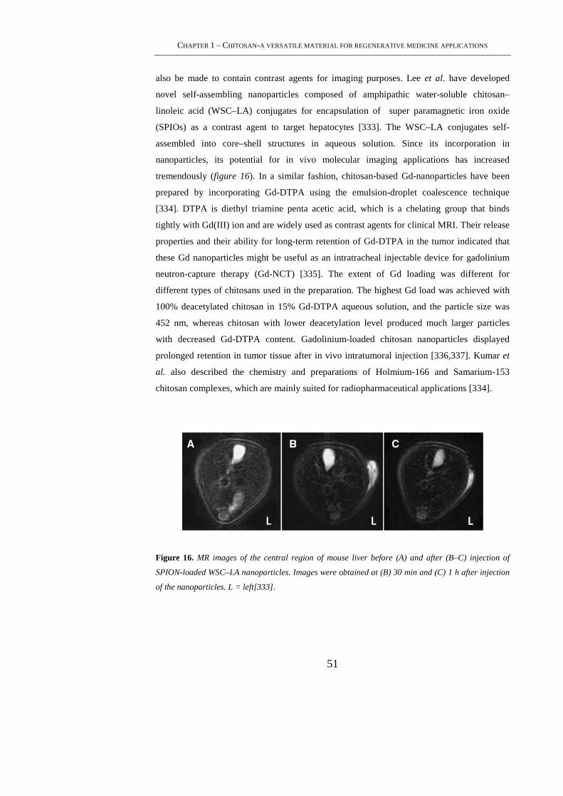
CHAPTER 1 – CHITOSAN-A VERSATILE MATERIAL FOR REGENERATIVE MEDICINE APPLICATIONS
51
also be made to contain contrast agents for imaging purposes. Lee et al. have developed
novel self-assembling nanoparticles composed of amphipathic water-soluble chitosan–
linoleic acid (WSC–LA) conjugates for encapsulation of super paramagnetic iron oxide
(SPIOs) as a contrast agent to target hepatocytes [333]. The WSC–LA conjugates self-
assembled into core–shell structures in aqueous solution. Since its incorporation in
nanoparticles, its potential for in vivo molecular imaging applications has increased
tremendously (figure 16). In a similar fashion, chitosan-based Gd-nanoparticles have been
prepared by incorporating Gd-DTPA using the emulsion-droplet coalescence technique
[334]. DTPA is diethyl triamine penta acetic acid, which is a chelating group that binds
tightly with Gd(III) ion and are widely used as contrast agents for clinical MRI. Their release
properties and their ability for long-term retention of Gd-DTPA in the tumor indicated that
these Gd nanoparticles might be useful as an intratracheal injectable device for gadolinium
neutron-capture therapy (Gd-NCT) [335]. The extent of Gd loading was different for
different types of chitosans used in the preparation. The highest Gd load was achieved with
100% deacetylated chitosan in 15% Gd-DTPA aqueous solution, and the particle size was
452 nm, whereas chitosan with lower deacetylation level produced much larger particles
with decreased Gd-DTPA content. Gadolinium-loaded chitosan nanoparticles displayed
prolonged retention in tumor tissue after in vivo intratumoral injection [336,337]. Kumar et
al. also described the chemistry and preparations of Holmium-166 and Samarium-153
chitosan complexes, which are mainly suited for radiopharmaceutical applications [334].
Figure 16. MR images of the central region of mouse liver before (A) and after (B–C) injection of
SPION-loaded WSC–LA nanoparticles. Images were obtained at (B) 30 min and (C) 1 h after injection
of the nanoparticles. L = left[333].
PHD THESIS – MAMONI DASH
52
1.5.5 Chitosan in wound healing applications
In the area of wound healing, an ideal dressing should protect the wound from
bacterial infection, provide a moist and healing environment, and be biocompatible [338].
Chitosan-based materials, produced in varying formulations, have been used in a number of
wound healing applications. Chitosan itself can induce faster wound healing and produce
smoother scarring, possibly due to enhanced vascularization and the supply of chito-
oligomers at the lesion site, which have been implicated in better collagen fibril
incorporation into the extracellular matrix [339,340]. While different material dressings have
been used to enhance endothelial cell proliferation, the delivery of growth factors involved in
the wound-healing process can improve that process [341]. Chitosan hydrogels take
advantage of the reparative nature of the polymer and simultaneously deliver a therapeutic
payload to the local wound. For instance, fibroblast growth factor-2 (FGF-2) stimulates
angiogenesis by activating capillary endothelial cells and fibroblasts [342,343]. In order to
sustain its residence at the wound site, the factor was incorporated into a high molecular
weight chitosan hydrogel, formed by UV-initiated cross-linking. The growth factor remained
bound tightly within the hydrogel until exposed to chitinase, after which it showed
bioactivity, indicating that there was no loss of functionality during the material preparation
[344]. Park et al. developed a chitosan hydrogel scaffold impregnated with bFGF-loaded
microspheres that can accelerate wound closure in the treatment of chronic ulcers [342].
1.6. Conclusions
Regenerative medicine has entered a new era with the development of modern
science and technology. The novel properties of chitosan make it one of the most promising
bio-based polymers for drug delivery, tissue engineering and gene therapy. Chitosan, a
native chitin derived polymer represents a vast resource with great medical potential. Current
studies show that, in general, chitosan is a relatively non-toxic, biocompatible material.
However, care must be taken to ensure that it is pure, as protein, metal or other contaminants
could potentially cause many deleterious effects both in crosslinking approaches and in
dosage forms. In this review we have seen how the unique cationic properties of chitosan
offer it to be an excellent biomaterial. We presented the various forms of chitosan, its
preparative procedures and its applications in drug delivery, tissue engineering, gene therapy
and bioimaging field. The various approaches on the preparation techniques presented herein
can be helpful to decide its use in the context of localized drug delivery to selectively capture
CHAPTER 1 – CHITOSAN-A VERSATILE MATERIAL FOR REGENERATIVE MEDICINE APPLICATIONS
53
a therapeutic payload and control its release in local proximity to its target or to use it for
tissue engineering purposes. The study demonstrates that for encapsulation and controlled
release using chitosan particle/hydrogel as carriers, there is a window of preparative
conditions for systematically manipulating the process of incorporation and for controlling
some properties, especially size and surface charge density etc. After crosslinking or any
such changes, unreacted reagents have to be thoroughly removed to prevent confounding
results as many reagents are cytotoxic if uncoupled. The biodistribution is both molecular
weight and formulation dependent, with relatively long circulation times achievable. The
liver appears to be a primary site of localization for chitosan. It should be appreciated that
many characteristics of chitosan affect its biological activity, including but not limited to: the
molecular weight, the DD, the salt form, and the superstructural form should be performed.
Chitosan has been shown to improve the dissolution rate of poorly soluble drugs and thus
can be exploited for bioavailability enhancement of such drugs making it an interesting
candidate for delivery applications. Various therapeutic agents such as anticancer, anti-
inflammatory, antibiotics, antithrombotic, steroids, proteins, amino acids, antidiabetic and
diuretics have been incorporated in chitosan based systems to achieve controlled release.
Recalling chitosan’s promise as a biopolymer for tissue engineering purposes, the possibility
to generate structures with predictable pore sizes and degradation rates makes it a suitable
material for bone and cartilage regeneration. However, efforts to improve the mechanical
properties of chitosan-based composite biomaterials are essential for this type of application.
One of a great ability of chitosan is its capability to bind anionic molecules such as growth
factors , glucosamine glycans and DNA. In fact, the combination of good biocompatibility,
intrinsic antibacterial activity, ability to bind to growth factors and to be processed in a
variety of different shapes makes chitosan an appropriate candidate as scaffold material for
cartilage, and bone tissue engineering in clinical practice. Moreover, the ability to link
chitosan to DNA molecules renders this material a good candidate as a substrate for gene
activated matrices in gene therapy applications. Another upcoming application related to
chitosan is in bioimaging, a survey about the recent advances has also been done, and it was
found that chitosan based particles provide an excellent template for this imaging
application. Although some of the parameters such as molecular weight, DD, viscosity have
to be considered to use chitosan at its full potential, the benefits are significant enough to
make the effort worthwhile.
PHD THESIS – MAMONI DASH
54
1.7. References
[1]. Conrad, C., Huss, R.; J Surg Res, 2005,201.
[2]. Wobus, A.M., Boheler, K.R.; Physiol Rev, 2005, 635.
[3]. Shahidi, F., Abuzaytoun, R., Adv Food Nutr, 2005, 93.
[4]. Hejazi, R., Amiji, M.; J Control Release, 2003, 151.
[5]. Khor, E., Lim, L.Y., Biomaterials, 2003, 2339.
[6] Rouget, C.;C.R.Acad. Sci. Ser. III ,1859, 792.
[7] Hirano, S., in Progress in Biomedical Polymers (Gebelein, G.G. and Dunn, R.L., eds),
1990,pp. 283–289, Plenum Press
[8] Muzzarelli, R.A.A.; in Natural Chelating Polymers:Alginic Acid, Chitin, and Chitosan
(Muzzarelli, R.A.A., ed.), 1973,pp. 83–252, Pergamon Press
[9] Braconnot, H.; Ann. Chim. Phys. 1811, 265.
[10] Mima, S.;J.Appl. Polym. Sci., 1983, 1909.
[11] Chandy, T., Sharma, C.P.; Biomater Artif Cells Artif Organs, 1990, 1.
[12] Paul, W., Sharma, C.P.; STP Pharma Sci, 2000, 5.
[13] Muzzarelli, R.A.A., Muzzarelli, C.; Adv Polym Sci ,2005, 151.
[14] Jayakumar, R., New, N., Tokura, S., Tamura, H.; Int J Biol Macromol , 2007,175.
[15] Rinaudo, M.; Polym Int, 2008, 397.
[16] Mourya, V.K., Inamdar, N.N.; React Funct Polym, 2008,1013.
CHAPTER 1 – CHITOSAN-A VERSATILE MATERIAL FOR REGENERATIVE MEDICINE APPLICATIONS
55
[17] Kurita, K.; Mar Biotechnol, 2006, 203.
[18] Hirano, S.; Polym Int, 1999, 732.
[19] Yi, H., Wu, L.Q., Bentley, W.E., Ghodssi, R., Rubloff, G.W., Culver, J.N.;
Biomacromolecules, 2005, 2881
[20] Kumar, M.N., Muzzarelli, R.A., Muzzarelli, C., Sashiwa, H., Domb, A.J., Chem Rev,
2004, 6017.
[21] Kurita, K., Polym Degrad Stabil, 1995, 117.
[22] Hirano, S.; Biotechnol Annu Rev, 1996, 237.
[23] Hoppe-Seiler, F.; Ber. Dtsch. Chem. Ges., 1994, 3329.
[24] Roberts, G.A.F.; Structure of chitin and chitosan in: G.A.F: Roberts (Ed), Chitin
Chemistry, MacMillan, Houndsmills, 1992, pp. 1-53.
[25] C.K.Rha, D. Rodrigues-Sanchez, C.Kienel-Sterzer, Novel applications of chitosan,
in:R.R.Colwell, E.R. Parsier, A.J.Sinkey (Eds.), Biotechnology of Marine Polysaccharides,
Hemisphere,Washington, 1984,pp.284-311.
[26] H. Struszcyk, D.Wawro, A.Niekraszewicz, Biodegradability of chitosan
fibres,in:C.J.Brine, PA. Stanford,J.P. Zikakis (Eds.), Advances in Chitin and Chitosan,
Elsiever Applied Science, London, 1991, pp.580-585.
[27] Suh, J.K.F., Matthew, H.W.T. ; Biomaterials, 2000, 2589.
[28] Wang,W., Xu, D.; Int. J. Biol. Macromol. , 1994, 149.
[29] Glerentes, P., Vachoud, L., Doury, J., Domard, A.; Biomaterials, 2002, 1295.
[30] Felt, O., Buri, P., Gurny, R.; Drug Dev. Ind. Pharm., 1998, 979.

PHD THESIS – MAMONI DASH
56
[31] Chatelet, C., Damour, O., Domard, A.; Biomaterials, 2001, 261.
[32] Hsu, S. C., Don, T. M., Chiu, W. Y.; Polym. Degrad. Stab., 2002 , 73.
[33] Zoldners, J., Kiseleva, T., Kaiminsh, I.; Carbohydr. Polym., 2005, 215.
[34] KEGG Pathway, Amino sugar and nucleotide sugar metabolism. 2009, Kanehisa
Laboratories.
[35] Kean, T., Thanou, M.; Chitin and chitosan—sources, production and medical
applications, in: P.A. Williams, R. Arshady (Eds.), Desk reference of Natural Polymers, their
Sources, Chemistry and Applications, Kentus Books, London, 2009, pp. 327–361.
[36] Funkhouser, J.D., Jr Aronson N.N., Chitinase family gh18: evolutionary insights from
the genomic history of a diverse protein family, BMC Evol. Biol. , 2007,96.
[37] Yang, Y.M., Hu,W., Wang, X.D., Gu, X.S.; J. Mater. Sci. Mater. Med., 2007, 2117.
[38] Xu, J., McCarthy, S.P., Gross, R.A., Kaplan, D.L.; Macromolecules, 1996, 3436.
[39] Onishi, H., Machida, Y.; Biomaterials, 1999, 175.
[40] Senel, S., McClure, S.J.; Adv. Drug Deliv. Rev., 2004, 1467
.
[41] Zhang, H., Neau, S.H., Biomaterials, 2002, 2761.
[42] Rao, S.B., Sharma, C.P.; J. Biomed. Mater. Res.,1997, 21.
[43] Kittur, F.S., Vishu Kumar, A.B., Tharanathan, R.N.; Carbohydr. Res., 2003, 1283.
[44] Kittur, F.S., Vishu Kumar, A.B., Varadaraj, M.C., Tharanathan, R.N.; Carbohydr. Res.,
2005, 1239.
[45] McConnell, E.L., Murdan, S., Basit, A.W.; J. Pharm. Sci. , 2008, 3820.
CHAPTER 1 – CHITOSAN-A VERSATILE MATERIAL FOR REGENERATIVE MEDICINE APPLICATIONS
57
[46] Guo, Z., Chen, R., Xing, R., Liu, S., Yu, H., Wang, P., Li, C., Li, P.; Carbohydr. Res.,
2006, 351.
[47] Ma, L., Gao, C., Mao, Z., Zhou, J., Shen, J. Hu, X., Han,C.; Biomaterials, 2003, 4833.
[48] Hirano, S., Seino, H., Akiyama, Y., Nonaka, I.; Proceedings of the ACS Division of
Polymeric Materials: Science and Engineering, American Chemical Society, Los Angeles,
California, 1988.
[49] Suzuki, Y.S., Momose,Y., Higashi, N., Shigematsu, A., Park, K.B., Kim,Y.M., Kim,
J.R., Ryu, J.M. ; J. Nucl. Med. ,1998, 2161.
[50] Banerjee, T., Mitra, S., Kumar Singh, A., Kumar Sharma, R., Maitra, A.; Int. J. Pharm.,
2002, 93.
[51] Richardson, S.C., Kolbe, H.V., Duncan, R.; Int. J. Pharm.,1999, 231.
[52] Line, B.R., Weber, P.B., Lukasiewicz, R., Dansereau, R.N.; J. Nucl. Med., 2000,1264.
[53] Kean, T., Thanou, M.; Adv. Drug Deliv. Rev., 2009, doi:10.1016/j.addr.2009.09.004
[54] Onishi, H., Machida, Y.; Biomaterials, 1999, 175.
[55] Kumar, R.M.N.V.; React. Funct. Polym. , 2000, 1.
[56] Xu, G., Huang, X., Qiu, L., Wu, J., Hu,Y.; Asia Pac. J. Clin. Nutr.; 2007,313.
[57] Chae, S.Y., Jang, M.K., Nah, J.W.; J. Control. Release , 2005, 383.
[58] Ishii, T., Okahata,Y., Sato,T.; Biochim. Biophys. Acta , 2001,51.
[59] Leong, K.W., Mao, H.Q., Truong-Le, V.L., Roy, K., Walsh, S.M., August, J.T.; J.
Control. Release ,1998,183.
PHD THESIS – MAMONI DASH
58
[60] Park, I.K., Kim, T.H., Kim, S.I., Park, Y.H., Kim, W.J., Akaike, T., Cho, C.S.; Int. J.
Pharm., 2003, 103.
[61] Janes, K.A., Fresneau, M.P., Marazuela, A., Fabra, A., Alonso, M. J.; J. Control.
Release, 2001, 255.
[62] Thanou, M., Verhoef, J.C., Junginger, H.E.; Adv. Drug Delivery Rev., 2001, 117.
[63] Illum, L.; Pharm. Res., 1998, 1326.
[64] Wedmore, I., McManus, J.G., Pusateri, A.E., Holcomb, J.B.; J. Trauma ,2006, 655.
[65] Schipper, N.G., Varum, K.M., Artursson, P.; Pharm. Res. , 1996, 1686.
[66] Schipper, N.G., Varum, K.M., Stenberg, P., Ocklind, G., Lennernas, H., Artursson, P.;
Eur. J. Pharm. Sci., 1999, 335.
[67] Zhang, C., Qu, G., Sun, Y., Wu, X., Yao, Z., Guo, Q., Ding, Q., Yuan, S., Shen, Z.,
Ping, Q., Zhou, H.; Biomaterials, 2008, 1233.
[68] Jumaa, M., Furkert, F.H., Muller, B.W.; Eur. J. Pharm. Biopharm., 2002, 115.
[69] Guo, Z., Chen, R., Xing, R., Liu, S., Yu, H., Wang, P., Li, C., Li, P.; Carbohydr. Res.,
2006, 351.
[70] Pujals, G., Sune-Negre, J.M., Perez, P., Garcia, E., Portus, M., Tico, J.R., Minarro, M.,
Carrio, J.; Parasitol. Res., 2008, 1243.
[71] Hirano, S., Iwata, M., Yamanaka, K., Tanaka, H., Toda, T., Inui, H.; Agric. Biol. Chem.,
1991, 2623.
[72] Rao, S.B., Sharma, C.P.; J. Biomed. Mater. Res.; 1997, 21.
[73] Gades, M.D., Stern, J.S., Obes. Res., 2003, 683.
CHAPTER 1 – CHITOSAN-A VERSATILE MATERIAL FOR REGENERATIVE MEDICINE APPLICATIONS
59
[74] Arai, K., Kinumaki, T., Fujita, T., Bull. Tokai Reg. Fish. Res. Lab., 1968, 89.
[75] Sonaje, K., Lin, Y.H., Juang, J.H., Wey, S.P., Chen, C.T., Sung, H.W.; Biomaterials,
2009, 2329.
[76] Illum, L., Farraj, N.F., Davis, S.S.; Pharm. Res., 1994, 1186.
[77] Muzzarelli, R.A.A., Jeuniauk, C., Gooday, G.W.; Chitin in Nature and Technology,
Plenum, New York, 1986.
[78] Sjak-Braek, G., Anthonsen, T., Sandford, P.; Chitin and Chitosan, Elsevier, New York,
1992.
[79] Hou, W.M., Miyazaki, S., Takada, M., Komai, T.; Chem. Pharm. Bull., 1985, 3986.
[80] Miyazaki, S., Ishii, K., Nadai, T.; Chem. Pharm. Bull., 1981, 3067.
[81] Handa, T., Kasai, A., Takenaka, H., Lin, S.Y., Ando, Y.; J. Pharm. Sci., 1985, 264.
[82] Miyazaki, S., Yamaguchi, H., Yokouchi, C., Takada, M., Hou, W. M.; Chem. Pharm.
Bull., 1988, 4033.
[83] Sawayanagi, Y., Nambu, N., Nagai, T.; Chem. Pharm. Bull.,1982, 4213.
[84] Shiraishi, S., Imai, T., Otagiri, M.; J. Control. Release, 1993, 217.
[85] Lehr, C.M., Bouwstra, J.A., Schacht, E.H., Junginger, H.E.; Int. J. Pharm., 1992, 43.
[86] Luehen, H.L., Lehr, C.M., Rentel, C.O., Noach, A.B.J., Boer, A.G., Verhoef, J.C.,
Junginger, H.E.; J. Control. Release, 1994, 329.
[87] Imai, T., Shiraishi, S., Saito, H., Otagiri, M., Int. J. Pharm., 1991, 11.
[88] Genta, I., Pavanetto, F., Conti, B., Giunchedi, P., Conte, U., Proc. Int. Symp. Control.
Release Bioact. Mater. 21 1994, 616.
PHD THESIS – MAMONI DASH
60
[89] Sawayanagi, Y., Nambu, N., Nagai, T., Chem. Pharm. Bull., 1983, 2507.
[90] Gallo, J.M., Hassan, E.E.; Pharm. Res. , 1988, 300.
[91] Hassan, E.E., Parish, R.C., Gallo, J.M.; Pharm. Res., 1992, 390.
[92] Artursson, P., Lindmark, T., Davis, S.S., lllum, L.; Pharm. Res., 1994, 1358.
[93] Soppimath, K.S., Aminabhavi, T.M., Kulkarni, A.R., Rudzinski, W.E.; J. Control.
Release, 2001, 1.
[94] Kreuter, J., Nanoparticles, in: J. Kreuter (Ed.), Colloidal Drug Delivery Systems, Marcel
Dekker, New York, 1994, pp. 219– 342.
[95] Brannon Peppas, L.; Int. J. Pharm., 1995, 1.
[96] Couvreur, P., Grislain, L., Lenaerts, V., Brasseur, F., Guiot, P.; in: P. Guiot, P. Couvreur
(Eds.), Polymeric Nanoparticles and Microspheres, CRC Press, Boca Raton, FL, 1986.
[97] Akbuga, J., Durmaz, G.; Int. J. Pharm., 1994, 217.
[98] Kumbar, S.G., Kulkarni, A.R., Aminabhavi, T.M.; J. Microencapsulation, 2002, 173.
[99] Sankar, C., Rani, M., Srivastava, A.K., Mishra, B.; Pharmazie, 2001, 223.
[100] Ozbas-Turan, S., Akbuga, J., Aral, C.; J. Pharm. Sci., 2002, 124 .
[101] Mao, H.Q., Roy, K., Troung-Le, V.L., Janes, K.A., Lim, K.Y., Wang, Y., August, J.T.,
Leong, K.W.; J. Control. Release , 2001, 399.
[102] He, P., Davis, S.S., Illum, L.; Int. J. Pharm., 1999, 53.
[103] Huang, Y.C., Yeh, M.K., Chiang, C.H.; Int. J. Pharm., 2002, 239.
CHAPTER 1 – CHITOSAN-A VERSATILE MATERIAL FOR REGENERATIVE MEDICINE APPLICATIONS
61
[104] Shi, X.Y., Tan, T.W.; Biomaterials, 2002, 4469.
[105] Bishop, C.W., Knutson, J.C., Valliere, C.R.; US Pat. 5 795 882, 1998.
[106] Tokumitsu, H., Ichikawa, H., Fukumori, Y.; Pharm. Res., 1999, 1830.
[107] Polk, A., Amsden, B., Yao, K.D., Peng, T., Goosen, M.F.A., J. Pharm. Sci., 1994,
178.
[108] Liu, L.S., Liu, S.Q., Ng, S.Y., Froix, M., Ohno, T., Heller, J.; J. Control. Release,
1997, 65.
[109] Kawashima, Y., Handa, T., Takenaka, H., Lin, S.Y., Ando, Y. ; J. Pharm. Sci., 1985,
264.
[110] Kawashima, Y., Handa, T., Kasai, A., Takenaka, H., Lin, S.Y.; Chem. Pharm. Bull.,
1985, 2469.
[111] Bodmeier, R., Oh, K.H., Pramar, Y.; Drug Dev. Ind. Pharm., 1989, 1475.
[112] Shirashi, S., Imai, T., Otagiri, M., J. Control. Release. 1993, 217.
[113] Sezer, A.D., Akbuga, J.; Int. J. Pharm. , 1995, 113.
[114] Aydin, Z., Akbuga, J.; Int. J. Pharm., 1996, 101.
[115] Calvo, P., Remunan-Lopez, C., Vila-Jata, J.L., Alonso, M.J., Pharm. Res., 1997, 1431.
[116] Calvo, P., Remunan-Lopez, C., Vila-Jata, J.L., Alonso, M. J., J. Appl. Polym. Sci.,
1997, 125.
[117] Shu, X.Z., Zhu, K.J.; Int. J. Pharm. , 2000, 51.
[118] Ko, J.A., Park, H.J., Hwang, S.J., Park, J.B., Lee, J.S.; Int. J. Pharm., 2002, 165.
[119] Xu, Y., Du, Y.; Int. J. Pharm., 2003, 215.
PHD THESIS – MAMONI DASH
62
[120] Leong, Y.S., Candau, F., J. Phys. Chem., 1982, 2269.
[121] Luisi, P.L., Giomini, M., Pileni, M.P., Robinson, B.H.; Biochim. Biophys. Acta, 1988,
209.
[122] Mitra, S., Gaur, U., Ghosh, P.C., Maitra, A.N.; J. Control. Release , 2001, 317.
[123] Agnihotri, S.A., Aminabhavi, T.M.; J. Control. Release, 2004, 245.
[124] Hejazi, R., Amiji, M.; Int. J. Pharm. , 2002, 87.
[125] Al-Helw, A.A., Al-Angary, A.A., Mahrous, G.M., Al- Dardari, M.M.; J.
Microencapsulation, 1998, 373.
[126] Ganza-Gonzalez, A., Anguiano-Igea, S., Otero-Espinar, F.J., Mendez, J.B., Eur. J.
Pharm. Biopharm., 1999, 149.
[127] Higuchi, T.; J. Pharm. Sci., 1963, 1145.
[128] Washington, C.; Int. J. Pharm., 1990, 1.
[129] Guy, R.H., Hadgraft, J., Kellaway, I.W., Taylor, M.J.; Int. J. Pharm., 1982, 199.
[130] Ritger, P.L., Peppas, N.A.; J. Control. Release , 1987, 37.
[131] N.A. Peppas, R.W. Korsmeyer, in: N.A. Peppas (Ed.), Hydrogels in Medicine and
Pharmacy, vol. 3, CRC Press, Boca Raton, FL, 1987, p. 103.
[132] Jameela, S.R., Kumary, T.V., Lal, A.V., Jayakrishnan, A.; J. Control. Release , 1998,
17.
[133] Berger, J., Reist, M., Mayer, J.M., Felt, O., Gurny, R.; Eur. J. Pharm. Biopharm.,
2004, 35.
[134] Boucard, N., Viton, C., Domard, A.; Biomacromolecules, 2005, 3227.
CHAPTER 1 – CHITOSAN-A VERSATILE MATERIAL FOR REGENERATIVE MEDICINE APPLICATIONS
63
[135] N.A. Peppas, Hydrogels in medicine and pharmacy, CRC Press, Boca Raton, FL,
1986.
[136] Shu, X.Z., Zhu, K.J.; Int. J. Pharm., 2002, 217.
[137] Shen, E.C., Wang, C., Fu, E., Chiang, C.Y., Chen, T.T., Nieh, S.; J. Periodontal. Res.,
2008, 642.
[138] Brack, H.P., Tirmizi, S.A., Risen, W.M., Polymer , 1997, 2351.
[139] Dambies, L., Vincent, T. Domard, A., Guibal, E.; Biomacromolecules, 2001, 1198.
[140] Berger, J., Reist, M., Mayer, J.M., Felt, O., Gurny, R.; Eur. J. Pharm. Biopharm.,
2004, 19.
[141] Meares, P.; J. Chem. Soc. Faraday Trans., 1983, 2264.
[142] Tsuchida, E., Abe, K.; Adv. Polym. Sci., 1982, 1.
[143] Cascone, M.G., Maltinti, S., Barbani, N., Laus, M.; J. Mater. Sci. Mater. Med., 1999,
431.
[144] Khan, F., Tare, R.S., Oreffo, R.O.C., Bradley, M., Angew. Chem. Int. Ed., 2009, 978.
[145] Boussif, O., Lezoualch, F., Zanta, M.A., Mergny, M.D., Scherman, D., Demeneix, B.,
Behr, J.P.; Proc. Natl Acad. Sci. U. S. A. 92 (1995) 7297–7301.
[146] Ladet, S., David, L., Domard, A.; Nature, 2008, 76.
[147] Chen, R.R., Silva, E.A., Yuen, W.W., Brock, A.A., Fischbach, C., Lin, A.S.,
Guldberg, R.E., Mooney, D.J.; FASEB J., 2007, 3896.
[148] Richardson, T.P., Peters, M.C., Ennett, A.B., Mooney, D.J., Nat. Biotechnol.,
2001,1029.
PHD THESIS – MAMONI DASH
64
[149] Jeong, B., Kim, S.W., Bae, Y.H.; Adv. Drug Deliv. Rev. , 2002, 37.
[150] J. Kretlow, D., Klouda, L., Mikos, A.G.; Adv. Drug Deliv. Rev., 2007, 263.
[151] Bhattarai, N., Matsen, F.A., Zhang, M.; Macromol. Biosci., 2005, 107.
[152] Bhattarai, N., Ramay, H.R., Gunn, J., Matsen, F.A., Zhang, M.Q.; J. Control. Release,
2005, 609.
[153] Boesel, L.F., Reis, R.L., Roman, J.S.; Tissue Eng. Part A, 2008, 223.
[154] Chen, J.P., Cheng, T.H.; Polymer, 2009, 107.
[151] Chenite, A., Chaput, C., Wang, D., Combes, C., Buschmann, M.D., Hoemann, C.D.,
Leroux, J.C., Atkinson, B.L., Binette, F., Selmani, A.; Biomaterials, 2000, 2155.
[156] Park, H., Park, K., Shalaby, W.S.W.; Biodegradable Hydrogels for Drug Delivery,
CRC Press, Boca Raton, FL, 1993.
[157] Hoare, T.R., Kohane, D.S.; Polymer , 2008, 1993.
[158] Berger, J., Reist, M., Mayer, J.M., Felt, O., Peppas, N.A., Gurny, R.; Eur. J. Pharm.
Biopharm., 2004, 19.
[159] Hennink, W.E., van Nostrum, C.F.; Adv. Drug Deliv. Rev., 2002, 13.
[160] Jin, J., Song, M., Hourston, D.J.; Biomacromolecules, 2004, 162.
[161] Sung, H.W., Liang, I.L., Chen, C.N., Huang, R.N., Liang, H.F., J. Biomed. Mater.
Res., 2001, 538.
[162] Sung, H.W., Huang, R.N., Huang, L.L.H., Tsai, C.C.; J. Biomater. Sci. Polym. Ed.,
1999, 63.
CHAPTER 1 – CHITOSAN-A VERSATILE MATERIAL FOR REGENERATIVE MEDICINE APPLICATIONS
65
[163] Mi, F.L., Tan, Y.C., Liang, H.C., Huang, R.N., Sung, H.W. ; Biomater. Sci. Polym.
Ed., 2001, 835.
[164] Chen, S.C., Wu, Y.C., Mi, F.L., Lin, Y.H., Yu, L.C., Sung, H.W.; J. Control. Release,
2004, 285.
[165] Bhattarai, N.; Adv. Drug Deliv. Rev., 2009, doi:10.1016/j.addr.2009.07.019
[166] Yoo, H.S.; J. Biomater. Sci. Polym. Ed. , 2007, 1429.
[167] Lee, J.I., Kim, H.S., Yoo, H.S.; Int. J. Pharm. , 2009, 93.
[168] Lee, S.J., Kim, S.S., Lee, Y.M.; Carbohydr. Polym. , 2000, 197.
[169] Yao, K.D., Liu, J., Cheng, G.X., Zhao, R.Z., Wang, W.H., Wei, L.; Polymer Int.,
1998, 191.
[170] She, Z., Jin, C., Huang, Z., Zhang, B., Feng, Q., Xu, Y.; J. Mater. Sci. Mater. Med.,
2008, 3545.
[171] Gupta, K.C., Kumar, M.; J. Appl. Polym. Sci., 2001, 639.
[172] Risbud, M.V., Hardikar, A.A., Bhat, S.V., Bhonde, R.R.; J. Control. Release, 2000,
23.
[173] Wang, M.Z., Fang, Y., Hu, D.D.; React. Funct. Polym., 2001, 215.
[174] Tessmar, J.K., Gopferich, A.M.; Adv. Drug Deliv. Rev., 2007, 274.
[175] Holland, T.A., Tessmar, J.K., Tabata, Y., Mikos, A.G.; J. Control. Release, 2004, 101.
[176] Kohane, D.S., Langer, R.; Pediatr. Res., 2008, 487.
[177] Zisch, A.H., Lutolf, M.P., Ehrbar, M., Raeber, G.P., Rizzi, S.C., Davies, N., Schmokel,
H., Bezuidenhout, D., Djonov, V., Zilla, P., Hubbell, J.A.; Faseb J. , 2003, 2260.

PHD THESIS – MAMONI DASH
66
[178] Lin, C.C., Anseth, K.S.; Pharm. Res., 2009, 631.
[179] Kim, S.W., Bae, Y.H., Okano, T.; Pharm. Res., 1992, 283.
[180] Sokker, H.H., Ghaffar, A.M.A., Gad, Y.H., Aly, A.S.; Carbohydr. Polym., 2009, 222.
[181] Hoare, T.R., Kohane, D.S.; Polymer, 2008, 1993.
[182] Ruel-Gariepy, E., Shive, M., Bichara, A., Berrada, M., Le Garrec, D., Chenite, A.,
Leroux, J.C.; Eur. J. Pharm. Biopharm., 2004, 53.
[183] Obara, K., Ishihara, M., Ozeki, Y., Ishizuka, T., Hayashi, T., Nakamura, S., Saito, Y.,
Yura, H., Matsui, T., Hattori, H., Takase, B., Kikuchi, M., Maehara, T.; J. Control. Release,
2005, 79.
[184] Jauhari, S., Dash, A.K.; AAPS PharmSciTech , 2006, E53.
[185] Lee, J.E., Kim, S.E., Kwon, I.C., Ahn, H.J., Cho, H., Lee, S.H., Kim, H.J., Seong,
S.C., Lee, M.C.; Artif. Organs ,2004, 829.
[186] Joung, Y.K., Choi, J.H., Park, K.M., Park, K.D.; Biomed. Mater., 2007, 269.
[187] Petersen, L.K., Narasimhan, B.; Expert Opin. Drug Deliv., 2008, 837.
[188] Lutolf, M.P., Hubbell, J.A.; Nat. Biotechnol., 2005, 47.
[189]. Shalak, R., Fox, C.F. Preface. In: Shalak R, Fox CF, eds. Tissue Engineering. New
York: Alan R. Liss, 1988:26.
[190]. Hutmacher, D.W., Schantz, T., Zein, I., Ng, K.W., Teoh, S.H., Tan, K.C.; J Biomed
Mater Res ,2001, 203.
[191] Seol, Y.J., Lee, J.Y., Park, Y.J., Lee, Y.M., Young-Ku, Rhyu, I.C., Lee, S.J., Han,
S.B., Chung, C.P.; Biotechnol Lett, 2004, 1037.
CHAPTER 1 – CHITOSAN-A VERSATILE MATERIAL FOR REGENERATIVE MEDICINE APPLICATIONS
67
[192] Seeherman, H., Li, R., Wozney, J.; J Bone Jt Surg Am, 2003, 96.
[193] Zhang, Y., Zhang, M.; J Biomed Mater Res, 2001, 304.
[194] Zhang, Y., Zhang, M.; J Biomed Mater Res, 2002, 378.
[195] Zhang, Y., Zhang, M.; J Biomed Mater Res, 2002, 1.
[196] Zhang, Y., Ni, M., Zhang, M., Ratner, B.; Tissue Eng ,2003, 337.
[197] Martino,A. D., Sittinger,Michael., Risbuda, M.V.; Biomaterials, 2005, 5983.
[198] Hu, Q., Li, B., Wang, M., Shen, J.; Biomaterials, 2004, 779.
[199] Yin, Y., Ye, F., Cui, J., Zhang, F., Li, X., Yao, K.; J Biomed Mater Res, 2003, 844.
[200] Leroux, L., Hatim, Z., Freche, M., Lacout, J.L.; Bone, 1999, 31S.
[201] Gutowska, A., Jeong, B., Jasionowski, M.; Anat Rec, 2001, 342.
[202] Xu, H.H., Quinn, J.B., Takagi, S., Chow, L.C.; Biomaterials, 2004, 1029.
[203] Zhao, F., Yin, Y., Lu, W.W., Leong, J.C., Zhang, W., Zhang, J.; Biomaterials, 2002,
3227.
[204] Kim, S.B., Kim, Y.J., Yoon, T.L., Park, S.A., Cho, I.H., Kim, E.J.; Biomaterials, 2004,
5715.
[205] Lee, B.H., Lee, Y.M., Sohn, Y.S., Song, S.C.; Macromolecules, 2002a,3876 .
[206] Lee, J.Y., Nam, S.H., Im, S.Y., Park, Y.J., Lee, Y.M., Seol, Y.J.; J Control Release,
2002b, 187.
[207] Zhao, L., Burguera, E. F., Xu, H.H.K., Amin, N., Ryou, H., Arola, D. D.;
Biomaterials, 2010, 840.
PHD THESIS – MAMONI DASH
68
[208] Grande, D.A., Halberstadt, C., Naughton, G., Schwartz, R., Ryhana, M.; J Biomed
Mater Res, 1997, 211.
[209] Kosher, R.A., Church, R.L.; Nature, 1975, 327.
[210] Kosher, R.A., Lash, J.W., Minor, R.R.; Dev Biol, 1973, 210.
[211] Athanasiou, K.A., Shah, A.R., Hernandez, R.J., LeBaron, R.G.; Clin Sports Med ,
2001, 223.
[212] Sittinger, M., Hutmacher, D.W., Risbud, M.V.; Curr Opin Biotechnol, 2004, 411.
[213] Suh, J.K.F., Matthew, H.W.T.; Biomaterials, 2000, 2589.
[214] Lahiji, A., Sohrabi, A., Hungerford, D.S., Frondoza, C.G., Lahiji, A., Sohrabi, A.,
Hungerford, D.S., Frondoza, C.G.; J Biomed Mater Res, 2000, 586
[215] Iwasaki, N., Yamane, S.T., Majima, T., Kasahara, Y., Minami, A., Harada, K.,
Nonaka, S., Maekawa, N., Tamura, H., Tokura, S., Shiono, M., Monde, K., Nishimura, S.;
Biomacromolecules, 2004, 828.
[216] Risbud, M., Ringe, J., Bhonde, R., Sittinger, M.; Cell Transplant , 2001, 755.
[217] Cui, Y.L., Qi, A.D., Liu, W.G., Wang, X.H., Wang, H., Ma, D.M., Yao, K.D.;
Biomaterials, 2003, 3859.
[218] Yamane, S., Iwasaki, N., Majima, T., Funakoshi, T., Masuko, T., Harada, K., Minami,
A., Monde, K., Nishimura, S.; Biomaterials, 2005, 611.
[219] Hsu, S.H., Whu, S.W., Hsieh, S.C., Tsai, C.L., Chen, D.C., Tan, T.S.; ArtifOrgans,
2004, 693.
[220] Lee, J.E., Kim, K.E., Kwon, I.C., Ahn, H.J., Lee, S.H., Cho, H., Kim, H.J., Seong,
S.C., Lee, M.C.; Biomaterials, 2004, 4163.
CHAPTER 1 – CHITOSAN-A VERSATILE MATERIAL FOR REGENERATIVE MEDICINE APPLICATIONS
69
[221] Taravel, M.N., Domard, A.; Biomaterials, 1996, 451.
[222] Kim, S.E., Park, J.H., Cho, Y.W., Chung, H., Jeong, S.Y., Lee, E.B., Kwon, I.C.; J
Control Release, 2003, 365.
[223] Lu, J.X., Prudhommeaux, F., Meunier, A., Sedel, L., Guillemin, G.; Biomaterials,
1999, 1937.
[224] Hoemann, C.D., Hurtig, M.B., Rossomacha, E., Sun, J., Chevrier, A., Shive, M.S.; J
Bone Joint Surg Am , 2005, 2671.
[225] Hoemann, C.D., Sun, J., McKee, M.D., Chevrier, A., Rossomacha, E., Rivard, G.E;
Osteoarthr Cartil , 2007, 78.
[226] Chevrier, A., Hoemann, C.D., Sun, J., Buschmann, M.D.; Osteoarthritis Cartilage,
2007, 316.
[227] Haoya, T., Wenza, N., Caoza, J. K., Wangy, H. B., Lu, S.H., Liuy, T., Liny, Q. X.,
Duany, C. M., Wangy C.Y.; Osteoarthritis and Cartilage, 2010, 257.
[228] Kim, I.Y., Seo, S.J., Moon, H.S., Jiang, H.L., Kim, Y.K., Cho, C.S.; Tissue Eng
Regenerative Med, 2006a, 27.
[229] Ben-Ze'ev, A., Robinson, G.S., Bucher, N.L., Farmer, S.R.; Proc Natl Acad Sci USA
,1988, 2161.
[230] LeCluyse, E.L., Bullock, P.L., Parkinson, A.; Adv Drug Deliv Rev, 1996, 133.
[231] Kang, I.K., Moon, J.S., Jeon, H.M., Meng, W., Kim, Y.I., Hwang, Y.J.; J Mater Sci
Mater Med , 2005, 533.
[232] Lindahl,U., Hook, M.; Annu Rev Biochem, 1978, 385.
[233] Li, J., Pan, J., Zhang, L., Guo, X., Yu, Y.; J Biomed Mater Res A, 2003a, 938.

PHD THESIS – MAMONI DASH
70
[234] Li, J., Pan, J., Zhang, L., Yu, Y.; Biomaterials, 2003b, 2317.
[235] Wang, X.H., Li, D.P., Wang, W.J., Feng, Q.L., Cui, F.Z., Xu, Y.X.; Biomaterials,
2003, 3213.
[236] Kim, I.Y., Seo, S. J., Moon, H.-S., Yoo, M.-K., Park, I.Y., Kim, B.-C., Cho,C.-S.;
Biotechnol. Adv., 2008, 1.
[237] Wang, X., Yan, Y., Lin, F., Xiong, Z., Wu, R., Zhang, R., J Biomater Sci Polym Ed,
2005, 1063.
[238] Adams, J.C.; J Cell Sci, 2002, 257.
[239] Ashwell, G., Morell, A.G.; Adv Enzymol, 1974, 99.
[240] Ashwell, G., Harford, J.; Ann Rev Biochem, 1982, 531.
[241] Chung, T.W., Lu, Y.F., Wang, S.S., Lin, Y.S., Chu, S.H.; Biomaterials ,2002a, 4803.
[242] Heath, C.A., Rutkowski, G.E.; TIBTECH, 1998, 163.
[243] Ciardelli, G., Chiono, V.; Macromol Biosci, 2006, 13.
[244] Haipeng, G., Yinghui, Z., Jianchun, L., Yandao, G., Nanming, Z., Xiufang, Z.; J
Biomed Mater Res, 2000, 285.
[245] Yuan, Y., Zhang, P., Yang, Y., Wang, X., Gu, X.; Biomaterials, 2004, 4273.
[246] Matsuda, A., Kobayashi, H., Itoh, S., Kataoka, K., Tanaka, J.; Biomaterials, 2005,
2273.
[247] Chávez-Delgado, M.E., Mora-Galindo, J., Gómez-Pinedo, U., Feria-Velasco, A.,
Castro-Castañeda, S., López-Dellamary Toral, F.A.; J Biomed Mater Res B, 2003, 702.
CHAPTER 1 – CHITOSAN-A VERSATILE MATERIAL FOR REGENERATIVE MEDICINE APPLICATIONS
71
[248] Mingyu, C., Kai, G., Jiamou, L., Yandao, G., Nanming, Z., Xiufang, Z.; J Biomater
Appl ,2004, 59.
[249] Cheng, M., Deng, J., Yang, F., Gong, Y., Zhao, N., Zhang, X.; Biomaterials, 2003,
2871.
[250] Freier, T., Montenegro, R., Shan Koh, H., Shoichet, M.S.; Biomaterials, 2005, 4624.
[251] Park, S.B., You, J.O., Park, H.Y., Haam, S.J., Kim, W.S.; Biomaterials, 2001, 323.
[252] Ahn, J.S., Choi, H.K., Cho, C.S.; Biomaterials, 2001, 923.
[253] Ahn, J.S., Choi, H.K., Chun, M.K., Ryu, J.M., Jung, J.H., Kim, Y.U., Cho, C.S.;
Biomaterials, 2002, 1411.
[254] Li, F., Liu, W.G., Yao, K.D.; Biomaterials, 2002, 343.
[255] Zhao, H.R., Wang, K., Zhao, Y., Pan, L.Q.; Biomaterials, 2002, 4459.
[256] Hu, Y., Jiang, X., Ding, Y., Ge, H., Yuan, Y., Yang, C.; Biomaterials, 2002, 3193.
[257]Akbuga, J., Bergisadi, N.; J. Microencapsul., 1999, 697.
[258] Shiraishi, S., Imai, T., Otagiri, M., J. Control Rel., 1993, 217.
[259] Aggarwal, A., Kaur, S., Tiwary, A.K., Gupta, S.; J. Microencapsul., 2001, 819.
[260] Hejazi, R., Amiji, M., Pharm. Dev. Technol., 2003, 253.
[261] Huang, Y.C., Yeh, M.K., Cheng, S.N., Chiang, C.H.; J. Microencapsul.,2003a. , 459.
[262] Huang, Y.C., Chiang, C.H., Yeh, M.K.; J. Microencapsul. 2003b, 247.
[263] Mattioli-Belmonte, M., Gigante, A., Muzzarelli, R.A., Politano, R., De Benedittis, A.,
Specchia, N., Buffa, A., Biagini, G., Greco, F.; Med. Biol. Eng. Comput., 1999,130.
PHD THESIS – MAMONI DASH
72
[264] Suh, J.K., Matthew, H.W.; Biomaterials, 2000, 2589.
[265] Muzzarelli, R.A.A., Biagini, G., Belmonte, M.A., Talassi, O., Gandolfi, M.G., Solmi,
R., Carraro, S., Giardino, R., Fini, M.; J. Bioact. Compat. Polym., 1997, 321.
[266] Lee, Y.M., Park, Y.J., Lee, S.J., Ku, Y., Han, S.B., Klokkevold, P.R., Chung, C.P.; J.
Periodontol., 2000, 418.
[267] Park, D.J., Choi, B.H., Zhu, S.J., Huh, J.Y., Kim, B.Y., Lee, S.H.; J. Cranio-maxillo-
facial Surg., 2005, 50.
[268] Patel, M., Mao, L., Wu, B., Vandevord, P.J.; J. Tissue Eng. Regen Med , 2007, 360.
[269] Elcin, Y.M., Dixit, V., Gitnick, G.; Artif. Cells Blood Substit. Immobil. Biotechnol.,
1996, 257.
[270] Azab, A.K., Kleinstern, J., Doviner, V., Orkin, B., Srebnik, M., Nissan, A., Rubinstein,
A.; J. Control. Release , 2007, 116.
[271] Azab, A.K., Orkin, B., Doviner, V., Nissan, A., Klein, M., Srebnik, M., Rubinstein, A.;
J. Control. Release, 2006, 281.
[272] Zeng, R., Tu, M., Liu, H., Zhao, J., Zha, Z., Zhou, C., Carbohydr. Polym., 2009, 107.
[273] Ho, M.H., Hsieh, C.C., Hsiao, S.W., Thien, D. V. H.; Carbohydr. Polym., 2010, 955.
[274] Sabera, A., Strandc, S.P., Ulfendahla, M.; Eur. J. Pharm. Biopharm., 2010, 110.
[275] Fernandez-Urrusuno, R., Calvo, P., Remunan-Lopez, C., Vila-Jato, J.L., Alonso, M.J.;
Pharm Res, 1999, 1576.
[276] Teijeiro-Osorio, D., Remunan-Lopez, C., Alonso, M.J.; Biomacromolecules, 2009,
243.
[277] Wang, X., Zheng, C., Wu, Z.M., Teng, D.G., Zhang, X., Wang, Z., Li, C.X.; J.
Biomed. Mater. Res. Part B Appl. Biomater., 2009, 150.
CHAPTER 1 – CHITOSAN-A VERSATILE MATERIAL FOR REGENERATIVE MEDICINE APPLICATIONS
73
[278] Zhang, X.G., Zhang, H.J., Wu, Z.M., Wang, Z., Niu, H.M., Li, C.X.; Eur. J. Pharm.
Biopharm., 2008, 526.
[279] Grenha, A., Grainger, C.I., Dailey, L.A., Seijo, B., Martin, G.P., Remunan-Lopez, C.,
Forbes, B.; Eur. J. Pharm. Biopharm., 2007,73.
[280] Grenha, A., Remunan-Lopez, C., Carvalho, E.L.S., Seijo, B.; Eur. J. Pharm.
Biopharm., 2008, 83.
[281] Grenha, A., Seijo, B., Remunan-Lopez, C.; Eur J Pharm Sci, 2005, 427.
[282] Yang, M., Velaga, S., Yamamoto, H., Takeuchi, H., Kawashima, Y., Hovgaard, L.,
van de Weert, M., Frokjaer, S.; Int J Pharm, 2007,176.
[283] Ma, L., Liu, C.; Colloids Surf B Biointerfaces, 2010,448.
[284] van der Lubben, I.M., Konings, F.A., Borchard, G., Verhoef, J.C., Junginger, H.E.; J
Drug Target, 2001, 39.
[285] van der Lubben, I.M., Verhoef, J.C., van Aelst, A.C., Borchard, G., Junginger, H.E.;
Biomaterials, 2001, 687.
[286] Vila, A., Sanchez, A., Janes, K., Behrens, I., Kissel, T., Vila Jato, J.L., Alonso, M.J.;
Eur J Pharm Biopharm, 2004, 123 .
[287] Illum, L., Jabbal-Gill, I., Hinchcliffe, M., Fisher, A.N., Davis, S.S.; Adv Drug Deliv
Rev, 2001, 81.
[288] Amidi, M., Romeijn, S.G., Verhoef, J.C., Junginger, H.E., Bungener, L., Huckriede,
A., Crommelin, D.J., Jiskoot, W., Vaccine, 2007, 144.
[289] Boonyo, W., Junginger, H.E., Waranuch, N., Polnok, A., Pitaksuteepong, T.; J.
Control. Release, 2007, 168.
PHD THESIS – MAMONI DASH
74
[290] Svirshchevskaya, E.V., Alekseeva, L.G., Reshetov, P.D., Phomicheva, N.N.,
Parphenyuk, S.A., Ilyina, A.V., Zueva, V.S., Lopatin, S.A., Levov, A.N., Varlamov, V.P.;
Eur J Med Chem, 2009, 2030.
[291] Ravichandran, E., Al-Saleem, F.H., Ancharski, D.M., Elias, M.D., Singh, A.K.,
Shamim, M., Gong, Y., Simpson, L.L.; Infect Immun, 2007, 3043.
[292] Sayin, B., Somavarapu, S., Li, X.W., Thanou, M. D.; Int J Pharm., 2008, 139.
[293] Borges, O., Cordeiro-da-Silva, A., Tavares, J., Santarem, N., de Sousa, A., Borchard,
G., Junginger, H.E.; Eur J Pharm Biopharm. 2008, 405.
[294] Kang, M.L., Jiang, H. L. Kang, S.G., Guo, D.D., Lee, D.Y., Cho, C.-S., Yoo, H.S.;
Vaccine, 2007, 4602.
[295] Jiang, H.L., Kang, M.L., Quan, J.S., Kang, S.G., Akaike, T., Yoo, H.S., Cho, C.S.;
Biomaterials, 2008, 1931.
[296] Klas, S.D., Petrie, C.R., Warwood, S.J., Williams, M.S., Olds, C.L., Stenz, J.P., Cheff,
A.M., Hinchcliffe, M., Richardson, C., Wimer, S.; Vaccine , 2008, 5494.
[297] Lameiro, M.H., Malpique, R., Silva, A.C., Alves, P.M., Melo, E.; J Biotechnol, 2006,
152.
[298] Jaganathan, K.S., Vyas, S.P.; Vaccine, 2006, 4201.
[299] Florindo, H.F., Pandit, S., Lacerda, L., Goncalves, L.M.D., Alpar, H.O., Almeida,
A.J.; Biomaterials, 2009, 879.
[300] N. Hagenaars, E. Mastrobattista, R. Verheul, I. Mooren, H. Glansbeek, J. Heldens, H.
van den Bosch, W. Jiskoot, Pharm. Res., 2009, 1353.
[301] Baudner, B.C., Giuliani, M.M., Verhoef, J.C., Rappuoli, R., Junginger, H.E., Giudice,
G.D., Vaccine, 2003,3837.
[302] Nagamoto, T., Hattori, Y., Takayama, K., Maitani, Y.; Pharm Res, 2004, 671.
CHAPTER 1 – CHITOSAN-A VERSATILE MATERIAL FOR REGENERATIVE MEDICINE APPLICATIONS
75
[303] Read, R.C., Naylor, S.C., Potter, C.W., Bond, J., Jabbal-Gill, I., Fisher, A., Illum, L.,
Jennings, R., Vaccine, 2005, 4367.
[304] Nishimura, K., Nishimura, S., Nishi, N., Numata, F., Tone, Y., Tokura, S., Azuma, I.;
Vaccine, 1985, 379.
[305] Nishimura, K., Nishimura, S., Nishi, N., Saiki, I., Tokura, S., Azuma, I.; Vaccine,
1984, 93.
[306] Nishimura, K., Ishihara, C., Ukei, S., Tokura, S., Azuma, I.; Vaccine, 1986, 151.
[307] Zaharoff, D.A., Rogers, C.J., Hance, K.W., Schlom, J., Greiner, J.W.; Vaccine, 2007,
8673.
[308] Zaharoff, D.A., Rogers, C.J., Hance, K.W., Schlom, J., Greiner, J.W., Vaccine, 2007,
2085.
[309] Ghendon, Y., Markushin, S., Krivtsov, G., Akopova, I., Archives of Virology, 2008,
831.
[310] Ghendon, Y., Markushin, S., Vasiliev, Y., Alkopova, I., Koptiaeva, I., Krivtsov, G.,
Borisova, O., Ahmatova, N., Kurbatova, E., Mazurina, S., Gervazieva, V.; Journal of
Medical Virology, 2009, 494.
[311] Sato, T., Ishii, T., Okahata, Y.; Biomaterials, 2001, 2075.
[312] Kawamata, Y., Nagayama, Y., Nakao, K., Mizuguchi, H., Hayakawa, T., Sato, T.,
Ishii, N.; Biomaterials, 2002, 4573.
[313] Khora, E., Limb, L.Y.; Biomaterials, 2003, 2339.
[314] Agnihotri, S.A., Mallikarjuna, N.N., Aminabhavi, T.M.; J Control Release, 2004; 5.
[315] Prabaharan, M., Mano, J.F.; Drug Delivery, 2005, 41.
PHD THESIS – MAMONI DASH
76
[316] Danielsen, S., Strand, S., de Lange Davies, C., Stokke, B.T.; Biochim Biophys Acta,
2005,1721.
[317] Mansouri, S., Lavigne, P., Corsi, K., Benderdour, M., Beaumont, E., Fernandes, J.C.;
Eur J Pharm Biopharm, 2004, 57.
[318] Masotti, A., Bordi, F., Ortaggi, G., Marino, F., Palocci, C.; Nanotechnology, 2008, 1.
[319] Dai, H., Jiang, X., Tan, G. C. Y., Chen, Y., Torbenson, M., Leong, K. W., et al; Int J
Nanomedicine, 2006, 507.
[320] Lee, J. M., Ha, K. S., & Yoo, H. S.; Acta Biomaterialia, 2008, 791.
[321] Lee, J. I., Kim, H. S., & Yoo, H. S.; Int. J. Pharm, 2009, 93.
[322] Khatri, K., Goyal, A. K., Gupta, P. N., Mishra, N., Vyas, S. P.; Int. J. Pharm, 2008,
235.
[323] Zhou, X. F., Zhang, X., Yu, X., Zha, X., Fu, Q., Liu, B., et al.; Biomaterials, 2009,
111.
[324] Katas, H., Alpar, H. O.; J Control Release, 2006, 216.
[325] Liu, X., Howard, K. A., Dong, M., Andersen, M. O., Rahbek, U. L., Johnsen, M. G., et
al.; Biomaterials, 2007, 1280.
[326] Lee, C.M., Jeong, H.J., Kim, S.L., Kim, E.M., Kim, D.W., Lim, S.T., Jang, K.Y.,
Jeong, Y.Y., Nah, J.W., Sohn, M.H.; Int. J. Pharm., 2009, 163.
[327] Hein, S., Wang, K., Stevens, W.F., Kjems, J.; Mater. Sci. Technol. , 2008, 1053.
[328] Köping-Höggård, M., Tubulekas, I., Guan, H., Edwards, K., Nilsson, M., Vårum,
K.M., Artursson, P.; Gene Ther. , 2001, 1108.
[329] Mi, F.L., Shyu, S.S., Peng, C.K., Wu, Y.B., Sung, H.W., Wang, P.S., Huang, C.C.; J.
Biomed. Mater. Res.— Part A, 2006 ,1.
CHAPTER 1 – CHITOSAN-A VERSATILE MATERIAL FOR REGENERATIVE MEDICINE APPLICATIONS
77
[330] Sionkowska, A., Wisniewski, M., Skopinska, J., Kennedy, C.J., Wess, T.J.;
Biomaterials, 2004 795.
[331] Hsu, S.H., Shu, W.W., Hsieh, S.C., Tsai, C.L., Chen, D.C., Tan, T.S.; Artif. Organs,
2004, 693.
[332] Kweon, D.K., Song, S.B., Park, Y.Y.; Biomaterials, 2003, 1595.
[333] Lee, C.M., Jeong, H.J., Kim, S.L., Kim, E.M., Kim, D.W., Lim, S.T., Jang, K.Y.,
Jeong, Y.Y., Nah, J.W., Sohn, M.H.; Int. J. Pharm., 2009, 163.
[334] Kumar, M.N., Muzzarelli, R.A., Muzzarelli, C., Sashiwa, H., Domb, A.J., Chem. Rev.,
2004, 6017.
[335] Tokumitsu H., Ichikawa, H. Fukumori, Y.; Pharm. Res. 1999, 1830.
[336] Saha, T.K., Ichikawa, H., Fukumori, Y.; Carbohydr. Res., 2006, 2835.
[337] Tokumitsu, H., Ichikawa, H., Saha, T.K., Fukumori, Y., Block, L.H.; S.T.P. Pharm.
Sci., 2000, 49.
[338] Wu, Z., Sheng, Z., Sun, T., Geng, M., Li, J., Yao, Y., Huang, Z.; Chin. Med. J.(Engl),
2003, 419.
[339] Shigemasa, Y., Minami, S.; Genet. Eng. Rev., 1996, 383.
[340] Rao, S.B., Sharma, C.P.; J. Biomed. Mater. Res., 1997, 21.
[341] Hunt, T.K., La Van, F.B.; N. Engl. J. Med,1989, 111.
[342] Park, C.J., Clark, S.G., Lichtensteiger, C.A., Jamison, R.D., Johnson, A.J.; Acta
Biomater, 2009.
PHD THESIS – MAMONI DASH
78
[343] Obara, K., Ishihara, M., Ishizuka, T., Fujita, M., Ozeki, Y., Maehara, T., Saito, Y.,
Yura, H., Matsui, T., Hattori, H., Kikuchi, M., Kurita, A.; Biomaterials, 2003, 3437.
[344] Ishihara, M., Nakanishi, K., Ono, K., Sato, M., Kikuchi, M., Saito, Y., Yura, H.,
Matsui, T., Hattori, H., Uenoyama, M., Kurita, A.; Biomaterials, 2002, 833.
79
2. STATISTICAL APPROACH OF CHITIN DEACETYLATION
2.1. Abstract
Chitosan was produced by thermo-chemical deacetylation of chitin. Reaction
parameters were varied to obtain different grade of degree of N-acetylation (DA) of chitin
following a statistical design. Two different analytical methods namely 1st derivative UV and
FTIR spectroscopies have been adopted to determine the values of DA of the prepared
chitosan. The values of DA assessed from the 1st derivative UV is in accordance with that
using FTIR. Thermogravimetric analysis was also performed to characterize chitin and its
derivatives in terms of thermal stability in air and nitrogen.
2.2. Introduction
Chitosan finds numerous applications in agriculture, biomedicine (for example, as
drug delivery system), papermaking, water treatment and food industry [1]. The properties of
chitosan strongly depend on the degree of N-acetylation (DA), which not only influences its
physical-chemical characteristics [2-7] but also its biodegradability [8-10] and
immunological activity [11].
Chitosan is derived from chitin and the percentage of N-acetyl group within the
polymer chain is a distinguishing factor between the different grades of these biopolymers
(Scheme 1). The macromolecule containing 100 % or more than 50 % of amine groups is
named chitosan. Conversely, the material will be considered chitin if in its structure there is
100 % or more than 50 % of N-acetyl group.
Various properties of these two biopolymers are closely related to the DA, which is
the most fundamental parameter. In other words, if the DA is known, many properties can be
predicted and different analytical methods have been employed for its assessment. These
methods included ninhydrin test [12], linear potentiometric titration [13], near-infrared
spectroscopy [14], nuclear magnetic resonance spectroscopy [15], hydrogen bromide
titrimetry [16, 17], infrared spectroscopy [17, 18], and UV-spectrophotometry [19, 20].
Some of these methods are either too tedious (titrimetry), or costly for routine analysis
(nuclear magnetic resonance spectroscopy), or destructive to the sample (ninhydrin test).
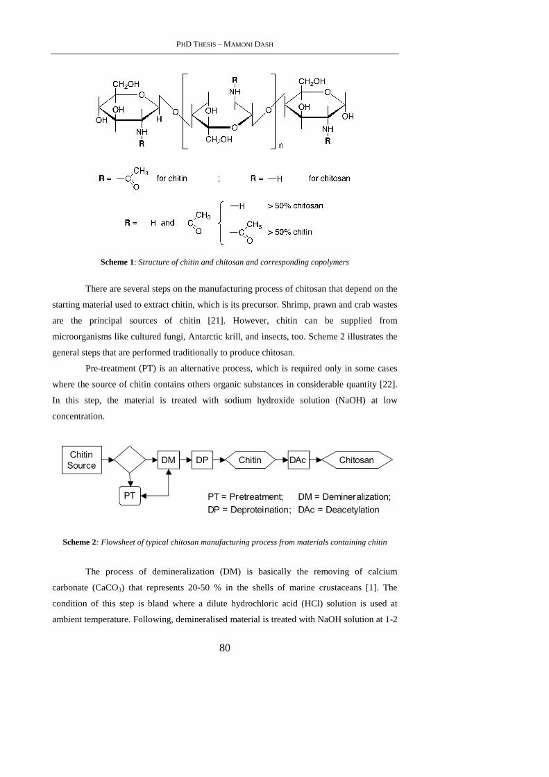
PHD THESIS – MAMONI DASH
80
Scheme 1: Structure of chitin and chitosan and corresponding copolymers
There are several steps on the manufacturing process of chitosan that depend on the
starting material used to extract chitin, which is its precursor. Shrimp, prawn and crab wastes
are the principal sources of chitin [21]. However, chitin can be supplied from
microorganisms like cultured fungi, Antarctic krill, and insects, too. Scheme 2 illustrates the
general steps that are performed traditionally to produce chitosan.
Pre-treatment (PT) is an alternative process, which is required only in some cases
where the source of chitin contains others organic substances in considerable quantity [22].
In this step, the material is treated with sodium hydroxide solution (NaOH) at low
concentration.
Scheme 2: Flowsheet of typical chitosan manufacturing process from materials containing chitin
The process of demineralization (DM) is basically the removing of calcium
carbonate (CaCO3) that represents 20-50 % in the shells of marine crustaceans [1]. The
condition of this step is bland where a dilute hydrochloric acid (HCl) solution is used at
ambient temperature. Following, demineralised material is treated with NaOH solution at 1-2

CHAPTER 2 – STATISTICAL APPROACH OF CHITIN DEACETYLATION
81
M and at temperatures higher than that of ambient. In this condition deproteination (DP) will
take place. The last step related to the chitin deacetylation (DAc) is the focus of the present
work. This step can follow a homogeneous or heterogeneous alkali method. In the first one,
temperatures are lower than that of heterogeneous DAc but with long times as for example
days. However, the conditions for an heterogeneous DAc of chitin generally uses aqueous
NaOH solution at concentration range of 40-50 wt-%, temperature range between 100-150
°C and short times [1, 21].
The aim of the present study is a statistical approach for the optimization of the
chitin deacetylation reaction variables using heterogeneous method.
2.3. Materials and Methods
2.3.1 Materials
Chitin from shrimp shells, practical grade powder, was purchased from Sigma (C-
7170) [1398-61-4]. Chitosan low molecular weight and DA=75-85%, was purchased from
Aldrich (448869) [9012-76-4]. D-(+)-glucosamine hydrochloride (GluN), purity 99%,
crystalline (G4875) [66-84-2], N-acetyl-D-glucosamine (GluNAc), purity 99%, (A8625)
[7512-17-6], and Potassium bromide (KBr), FTIR grade (221864) [7758-02-3], were
purchased from Sigma. Sodium hydroxide pellets and acetic acid were obtained from Carlo
Erba and were analytical grades.
2.3.2 Methods
2.3.2.1 Chitin Deacetylation
A screening design of experimente (DEX) for chitin deacetylation process was
carried out following a factorial 22 with center point [23]. Tables 1 and 2 present levels of
variables reaction time and temperature and sample codes for the corresponding processing
conditions, respectively.
Table 1: Settings for the 22 design with center point
Variable Levelsa)
-1 0 +1
Time (h) 1 2 3
Temperature (°C) 90 110 130
a) -1 and +1 are low and high levels and 0 is center point.
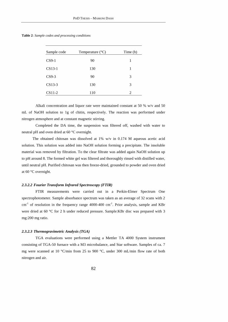
PHD THESIS – MAMONI DASH
82
Table 2: Sample codes and processing conditions
Sample code Temperature (°C) Time (h)
CS9-1 90 1
CS13-1 130 1
CS9-3 90 3
CS13-3 130 3
CS11-2 110 2
Alkali concentration and liquor rate were maintained constant at 50 % w/v and 50
mL of NaOH solution to 1g of chitin, respectively. The reaction was performed under
nitrogen atmosphere and at constant magnetic stirring.
Completed the DA time, the suspension was filtered off, washed with water to
neutral pH and oven dried at 60 °C overnight.
The obtained chitosan was dissolved at 1% w/v in 0.174 M aqueous acetic acid
solution. This solution was added into NaOH solution forming a precipitate. The insoluble
material was removed by filtration. To the clear filtrate was added again NaOH solution up
to pH around 8. The formed white gel was filtered and thoroughly rinsed with distilled water,
until neutral pH. Purified chitosan was then freeze-dried, grounded to powder and oven dried
at 60 °C overnight.
2.3.2.2 Fourier Transform Infrared Spectroscopy (FTIR)
FTIR measurements were carried out in a Perkin-Elmer Spectrum One
spectrophotometer. Sample absorbance spectrum was taken as an average of 32 scans with 2
cm-1 of resolution in the frequency range 4000-400 cm-1. Prior analysis, sample and KBr
were dried at 60 °C for 2 h under reduced pressure. Sample:KBr disc was prepared with 3
mg:200 mg ratio.
2.3.2.3 Thermogravimetric Analysis (TGA)
TGA evaluations were performed using a Mettler TA 4000 System instrument
consisting of TGA-50 furnace with a M3 microbalance, and Star software. Samples of ca. 7
mg were scanned at 10 °C/min from 25 to 900 °C, under 300 mL/min flow rate of both
nitrogen and air.
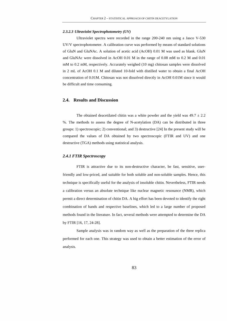
CHAPTER 2 – STATISTICAL APPROACH OF CHITIN DEACETYLATION
83
2.3.2.3 Ultraviolet Spectrophotometry (UV)
Ultraviolet spectra were recorded in the range 200-240 nm using a Jasco V-530
UV/V spectrophotometer. A calibration curve was performed by means of standard solutions
of GluN and GluNAc. A solution of acetic acid (AcOH) 0.01 M was used as blank. GluN
and GluNAc were dissolved in AcOH 0.01 M in the range of 0.08 mM to 0.2 M and 0.01
mM to 0.2 mM, respectively. Accurately weighed (10 mg) chitosan samples were dissolved
in 2 mL of AcOH 0.1 M and diluted 10-fold with distilled water to obtain a final AcOH
concentration of 0.01M. Chitosan was not dissolved directly in AcOH 0.01M since it would
be difficult and time consuming.
2.4. Results and Discussion
The obtained deacetilated chitin was a white powder and the yield was 49.7 ± 2.2
%. The methods to assess the degree of N-acetylation (DA) can be distributed in three
groups: 1) spectroscopic; 2) conventional; and 3) destructive [24] In the present study will be
compared the values of DA obtained by two spectroscopic (FTIR and UV) and one
destructive (TGA) methods using statistical analysis.
2.4.1 FTIR Spectroscopy
FTIR is attractive due to its non-destructive character, be fast, sensitive, user-
friendly and low-priced, and suitable for both soluble and non-soluble samples. Hence, this
technique is specifically useful for the analysis of insoluble chitin. Nevertheless, FTIR needs
a calibration versus an absolute technique like nuclear magnetic resonance (NMR), which
permit a direct determination of chitin DA. A big effort has been devoted to identify the right
combination of bands and respective baselines, which led to a large number of proposed
methods found in the literature. In fact, several methods were attempted to determine the DA
by FTIR [16, 17, 24-28].
Sample analysis was in random way as well as the preparation of the three replica
performed for each one. This strategy was used to obtain a better estimation of the error of
analysis.
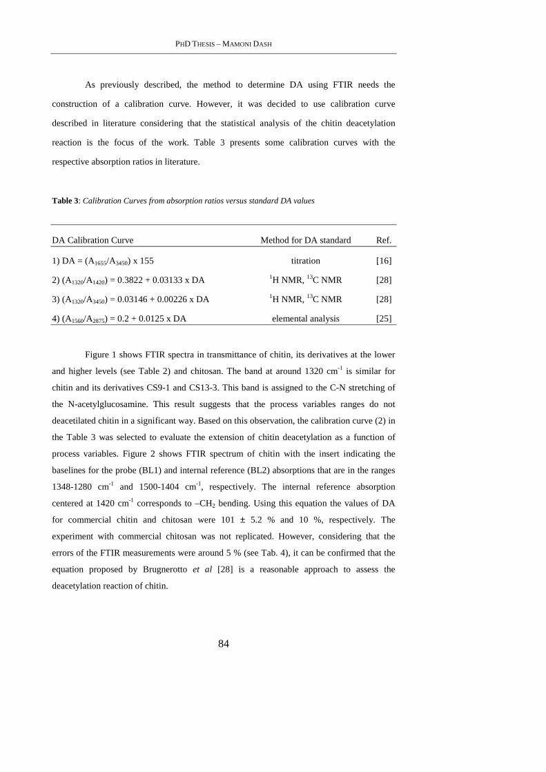
PHD THESIS – MAMONI DASH
84
As previously described, the method to determine DA using FTIR needs the
construction of a calibration curve. However, it was decided to use calibration curve
described in literature considering that the statistical analysis of the chitin deacetylation
reaction is the focus of the work. Table 3 presents some calibration curves with the
respective absorption ratios in literature.
Table 3: Calibration Curves from absorption ratios versus standard DA values
DA Calibration Curve Method for DA standard Ref.
1) DA = (A1655/A3450) x 155 titration [16]
2) (A1320/A1420) = 0.3822 + 0.03133 x DA 1H NMR, 13C NMR [28]
3) (A1320/A3450) = 0.03146 + 0.00226 x DA 1H NMR, 13C NMR [28]
4) (A1560/A2875) = 0.2 + 0.0125 x DA elemental analysis [25]
Figure 1 shows FTIR spectra in transmittance of chitin, its derivatives at the lower
and higher levels (see Table 2) and chitosan. The band at around 1320 cm-1 is similar for
chitin and its derivatives CS9-1 and CS13-3. This band is assigned to the C-N stretching of
the N-acetylglucosamine. This result suggests that the process variables ranges do not
deacetilated chitin in a significant way. Based on this observation, the calibration curve (2) in
the Table 3 was selected to evaluate the extension of chitin deacetylation as a function of
process variables. Figure 2 shows FTIR spectrum of chitin with the insert indicating the
baselines for the probe (BL1) and internal reference (BL2) absorptions that are in the ranges
1348-1280 cm-1 and 1500-1404 cm-1, respectively. The internal reference absorption
centered at 1420 cm-1 corresponds to –CH2 bending. Using this equation the values of DA
for commercial chitin and chitosan were 101 ± 5.2 % and 10 %, respectively. The
experiment with commercial chitosan was not replicated. However, considering that the
errors of the FTIR measurements were around 5 % (see Tab. 4), it can be confirmed that the
equation proposed by Brugnerotto et al [28] is a reasonable approach to assess the
deacetylation reaction of chitin.
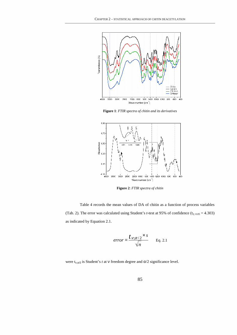
CHAPTER 2 – STATISTICAL APPROACH OF CHITIN DEACETYLATION
85
Figure 1: FTIR spectra of chitin and its derivatives
Figure 2: FTIR spectra of chitin
Table 4 records the mean values of DA of chitin as a function of process variables
(Tab. 2). The error was calculated using Student’s t-test at 95% of confidence (t2; 0.05 = 4.303)
as indicated by Equation 2.1.
error = ν ;α / 2t × s
n Eq. 2.1
were tν,α/2 is Student’s t at ν freedom degree and α/2 significance level.
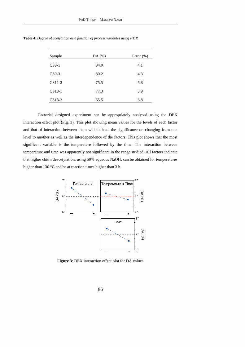
PHD THESIS – MAMONI DASH
86
Table 4: Degree of acetylation as a function of process variables using FTIR
Sample DA (%) Error (%)
CS9-1 84.0 4.1
CS9-3 80.2 4.3
CS11-2 75.5 5.8
CS13-1 77.3 3.9
CS13-3 65.5 6.8
Factorial designed experiment can be appropriately analysed using the DEX
interaction effect plot (Fig. 3). This plot showing mean values for the levels of each factor
and that of interaction between them will indicate the significance on changing from one
level to another as well as the interdependence of the factors. This plot shows that the most
significant variable is the temperature followed by the time. The interaction between
temperature and time was apparently not significant in the range studied. All factors indicate
that higher chitin deacetylation, using 50% aqueous NaOH, can be obtained for temperatures
higher than 130 °C and/or at reaction times higher than 3 h.
Figure 3: DEX interaction effect plot for DA values
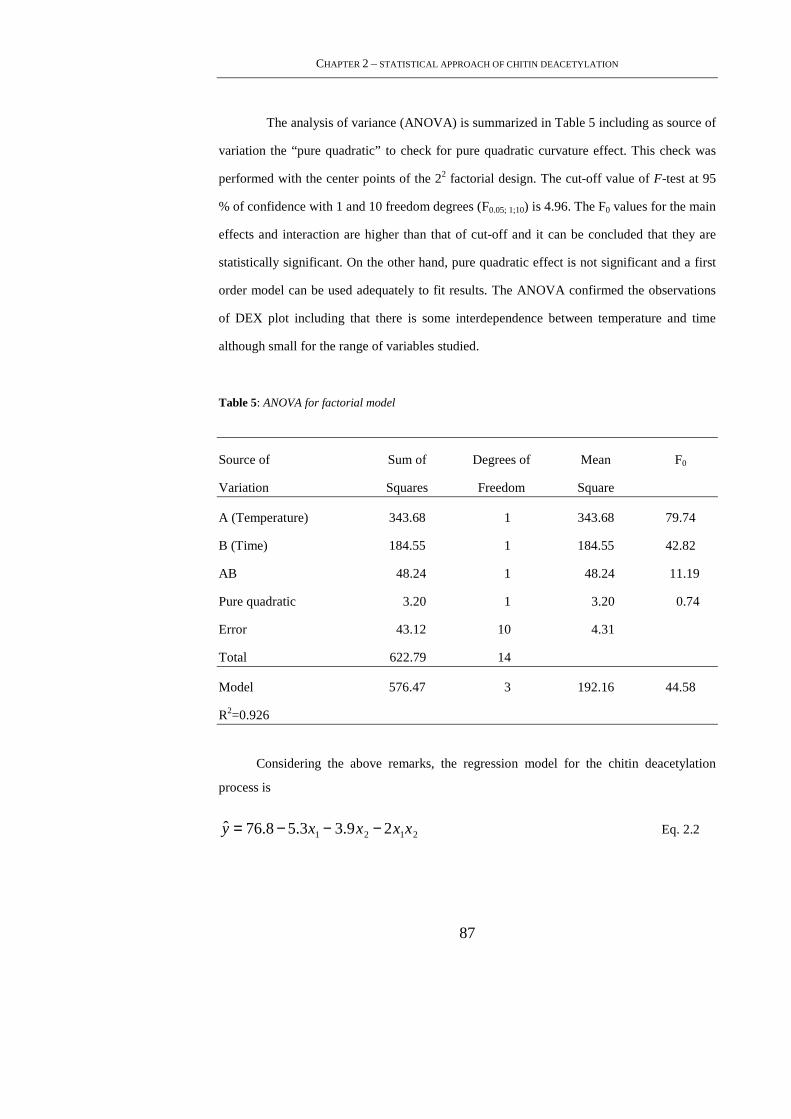
CHAPTER 2 – STATISTICAL APPROACH OF CHITIN DEACETYLATION
87
The analysis of variance (ANOVA) is summarized in Table 5 including as source of
variation the “pure quadratic” to check for pure quadratic curvature effect. This check was
performed with the center points of the 22 factorial design. The cut-off value of F-test at 95
% of confidence with 1 and 10 freedom degrees (F0.05; 1;10) is 4.96. The F0 values for the main
effects and interaction are higher than that of cut-off and it can be concluded that they are
statistically significant. On the other hand, pure quadratic effect is not significant and a first
order model can be used adequately to fit results. The ANOVA confirmed the observations
of DEX plot including that there is some interdependence between temperature and time
although small for the range of variables studied.
Table 5: ANOVA for factorial model
Source of Sum of Degrees of Mean F0
Variation Squares Freedom Square
A (Temperature) 343.68 1 343.68 79.74
B (Time) 184.55 1 184.55 42.82
AB 48.24 1 48.24 11.19
Pure quadratic 3.20 1 3.20 0.74
Error 43.12 10 4.31
Total 622.79 14
Model 576.47 3 192.16 44.58
R2=0.926
Considering the above remarks, the regression model for the chitin deacetylation
process is
ˆ y = 76.8− 5.3x1 − 3.9x2 − 2x1x2 Eq. 2.2
PHD THESIS – MAMONI DASH
88
The relationship between coded and natural variables is
x1 =Temp− (Templow + Temphigh) /2
(Temphigh − Templow) /2 Eq. 2.3
x2 =Tempo− (Tempolow + Tempohigh) /2
(Tempohigh − Tempolow) /2 Eq. 2.4
Consequently, the fitted model of Eq. 2.2 with the natural variables is
D ˆ A =118.64− 0.22T − 6.34t − 0.02Tt Eq. 2.5
where, T and t are Temperature and time variables.
The ANOVA for the model is included in Table 5. The cut-off value of F0.05; 3;10 is
3.71 that is lower than that found for the model. This means that at least one coefficient of
the model is different of zero. Beside, below the ANOVA of model, are reported a statistic to
check adequacy of fit of the model. This statistic represents the fraction of the variation
about the mean that is explained by the fitted model. So, R2 value suggests that the model
can be explain about 93% of DA variability.
Using the model represented by Eq. 2.5 it can be said that to obtain chitosan with
20% of DA using NaOH at 50% and a reaction temperature of 100°C it is needed about 9
hours.
2.4.2 TGA
The TGA method for chitin and chitosan derivates has been used principally on
thermodegradation kinetic studies [29,30]. However, a simple way to determine chitin DA
was proposed by Alonso et al. [31] They take the weight loss in air atmosphere that
corresponded to the maximum of DTG peak of chitin and chitosan degradation traces and
correlated with DA of chitin standards. They demonstrated that the empirical correlation
obtained could be a fast way to control DA.
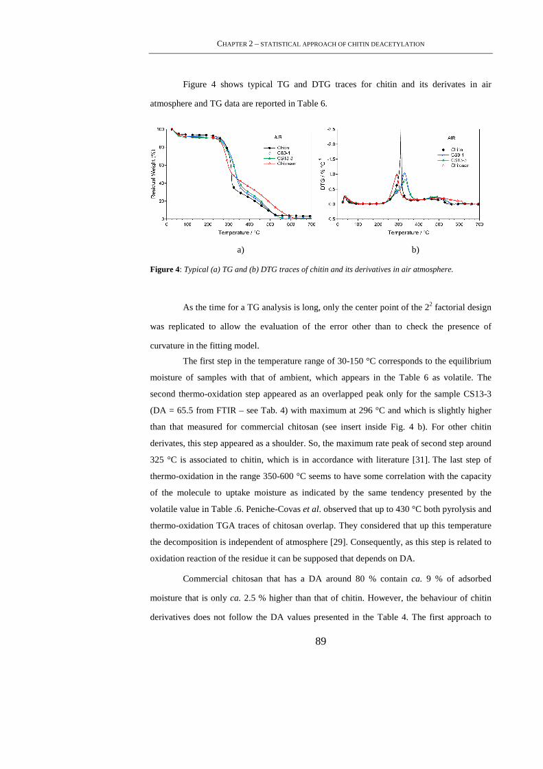
CHAPTER 2 – STATISTICAL APPROACH OF CHITIN DEACETYLATION
89
Figure 4 shows typical TG and DTG traces for chitin and its derivates in air
atmosphere and TG data are reported in Table 6.
a) b)
Figure 4: Typical (a) TG and (b) DTG traces of chitin and its derivatives in air atmosphere.
As the time for a TG analysis is long, only the center point of the 22 factorial design
was replicated to allow the evaluation of the error other than to check the presence of
curvature in the fitting model.
The first step in the temperature range of 30-150 °C corresponds to the equilibrium
moisture of samples with that of ambient, which appears in the Table 6 as volatile. The
second thermo-oxidation step appeared as an overlapped peak only for the sample CS13-3
(DA = 65.5 from FTIR – see Tab. 4) with maximum at 296 °C and which is slightly higher
than that measured for commercial chitosan (see insert inside Fig. 4 b). For other chitin
derivates, this step appeared as a shoulder. So, the maximum rate peak of second step around
325 °C is associated to chitin, which is in accordance with literature [31]. The last step of
thermo-oxidation in the range 350-600 °C seems to have some correlation with the capacity
of the molecule to uptake moisture as indicated by the same tendency presented by the
volatile value in Table .6. Peniche-Covas et al. observed that up to 430 °C both pyrolysis and
thermo-oxidation TGA traces of chitosan overlap. They considered that up this temperature
the decomposition is independent of atmosphere [29]. Consequently, as this step is related to
oxidation reaction of the residue it can be supposed that depends on DA.
Commercial chitosan that has a DA around 80 % contain ca. 9 % of adsorbed
moisture that is only ca. 2.5 % higher than that of chitin. However, the behaviour of chitin
derivatives does not follow the DA values presented in the Table 4. The first approach to
PHD THESIS – MAMONI DASH
90
explain this result can be related to the formation of some kind of intermolecular interaction
that turn less accessible the hydrophilic groups for moisture adsorption. The thermo-
oxidation temperature defined at 2 wt-% of weight loss after that of volatile (Td) for chitin
was 243 °C suggesting be 2 °C less stable than chitosan (DA=80%). However, considering
the replication of the experiment with the center point sample (CS11-2) and using Student’s
t-test at 95% of confidence (Eq. 2.1), it can be said that the error of the experiment is around
3.8 °C. In conclusion, the difference observed on Td value between chitin and chitosan is not
significant. The same statement can be formulated for chitin derivates.
Table 6. TGA data of chitin and its derivatives in air atmosphere a)
Sampleb) Volatile Td ∆M1 Tp1 ∆M2 Tp2 R600
(%) (°C) (%) (°C) (%) (°C) (%)
Chitin 6.3 243 61.8 313 28.0 519 3.9
CS9-1 8.1 248 63.6 330 27.0 479 1.3
CS13-1 6.7 244 61.4 324 29.7 475 2.2
CS9-3 7.1 244 65.7 324 25.5 479 1.7
CS13-3 3.4 245 64.7 329 29.5 481 2.4
CS11-2 3.9 240 65.0 324 29.8 477 1.3
CS11-2 3.9 243 64.0 325 30.6 485 1.5
CS11-2 3.3 241 64.2 325 30.0 487 2.5
Chitosan 8.8 245 54.0 292 34.2 493 3.0
a) Volatile means the weight loss up to 150 °C. Td is the decomposition temperature defined at 2 wt-%
of weight loss from 150 °C; Tp is the first derivative peak; and R600 is the residual weight at 600°C. b)
See Table 2.2 for code definition.
The residue at 600 °C (R600) was a white powder that characterize the inorganic
molecules present in the crustaceous shell. Pristine chitin left ca. 4% and the commercial
chitosan 3%. The R600 values of the chitin derivatives were lower than the two limits of kind
of 2-deoxy-β-D-glucopyranose materials. This is one indication that the presence of
inorganic impurities depends on the purification method used. Although the results suggest
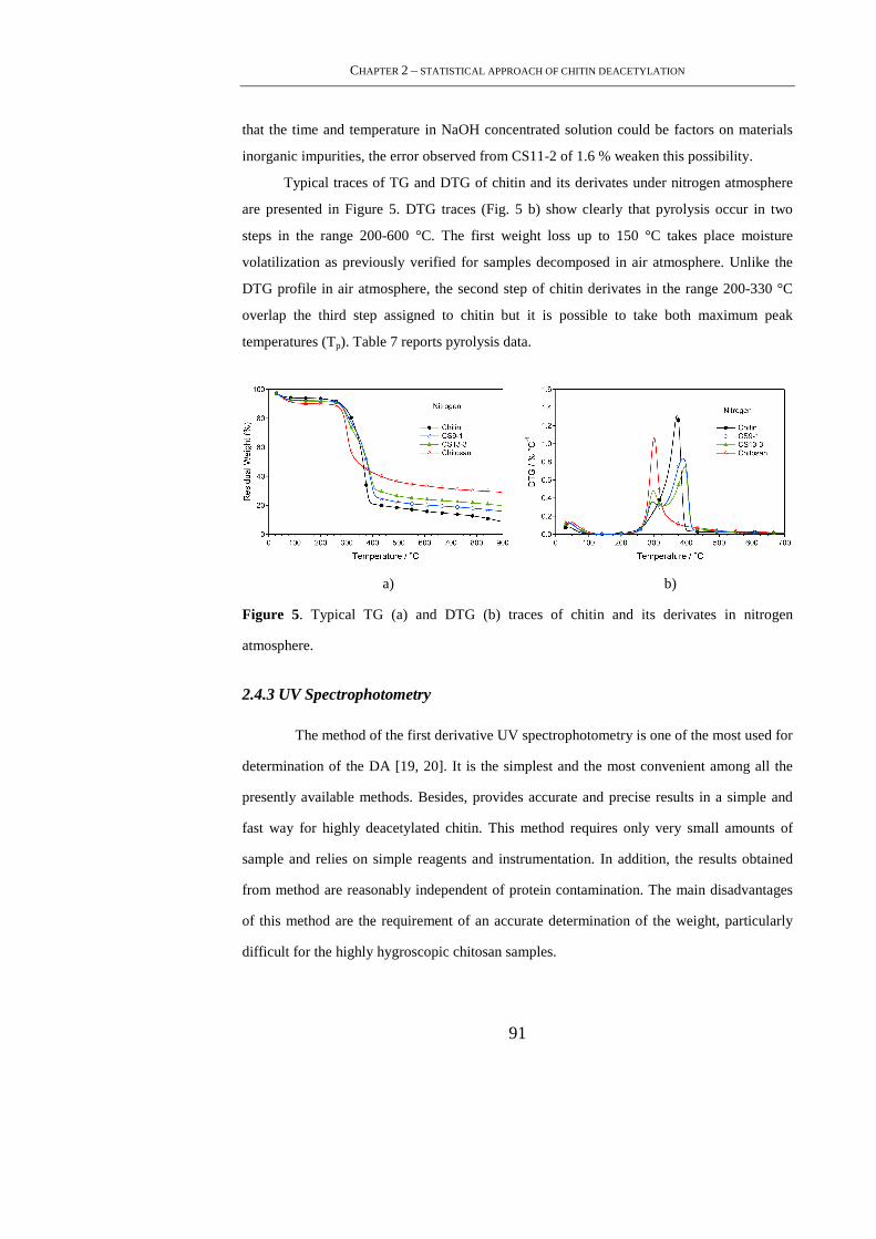
CHAPTER 2 – STATISTICAL APPROACH OF CHITIN DEACETYLATION
91
that the time and temperature in NaOH concentrated solution could be factors on materials
inorganic impurities, the error observed from CS11-2 of 1.6 % weaken this possibility.
Typical traces of TG and DTG of chitin and its derivates under nitrogen atmosphere
are presented in Figure 5. DTG traces (Fig. 5 b) show clearly that pyrolysis occur in two
steps in the range 200-600 °C. The first weight loss up to 150 °C takes place moisture
volatilization as previously verified for samples decomposed in air atmosphere. Unlike the
DTG profile in air atmosphere, the second step of chitin derivates in the range 200-330 °C
overlap the third step assigned to chitin but it is possible to take both maximum peak
temperatures (Tp). Table 7 reports pyrolysis data.
a) b)
Figure 5. Typical TG (a) and DTG (b) traces of chitin and its derivates in nitrogen
atmosphere.
2.4.3 UV Spectrophotometry
The method of the first derivative UV spectrophotometry is one of the most used for
determination of the DA [19, 20]. It is the simplest and the most convenient among all the
presently available methods. Besides, provides accurate and precise results in a simple and
fast way for highly deacetylated chitin. This method requires only very small amounts of
sample and relies on simple reagents and instrumentation. In addition, the results obtained
from method are reasonably independent of protein contamination. The main disadvantages
of this method are the requirement of an accurate determination of the weight, particularly
difficult for the highly hygroscopic chitosan samples.
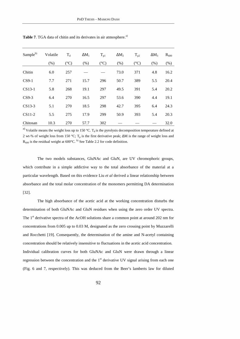
PHD THESIS – MAMONI DASH
92
Table 7. TGA data of chitin and its derivates in air atmosphere.a)
Sampleb) Volatile Td ∆M1 Tp1 ∆M2 Tp2 ∆M3 R600
(%) (°C) (%) (°C) (%) (°C) (%) (%)
Chitin 6.0 257 — — 73.0 371 4.8 16.2
CS9-1 7.7 271 15.7 296 50.7 389 5.5 20.4
CS13-1 5.8 268 19.1 297 49.5 391 5.4 20.2
CS9-3 6.4 270 16.5 297 53.6 390 4.4 19.1
CS13-3 5.1 270 18.5 298 42.7 395 6.4 24.3
CS11-2 5.5 275 17.9 299 50.9 393 5.4 20.3
Chitosan 10.3 270 57.7 302 — — — 32.0 a)
Volatile means the weight loss up to 150 °C. Td is the pyrolysis decomposition temperature defined at
2 wt-% of weight loss from 150 °C; Tp is the first derivative peak; ∆M is the range of weight loss and
R600 is the residual weight at 600°C. b) See Table 2.2 for code definition.
The two models substances, GluNAc and GluN, are UV chromophoric groups,
which contribute in a simple addictive way to the total absorbance of the material at a
particular wavelength. Based on this evidence Liu et al derived a linear relationship between
absorbance and the total molar concentration of the monomers permitting DA determination
[32].
The high absorbance of the acetic acid at the working concentration disturbs the
determination of both GluNAc and GluN residues when using the zero order UV spectra.
The 1st derivative spectra of the AcOH solutions share a common point at around 202 nm for
concentrations from 0.005 up to 0.03 M, designated as the zero crossing point by Muzzarelli
and Rocchetti [19]. Consequently, the determination of the amine and N-acetyl containing
concentration should be relatively insensitive to fluctuations in the acetic acid concentration.
Individual calibration curves for both GluNAc and GluN were drawn through a linear
regression between the concentration and the 1st derivative UV signal arising from each one
(Fig. 6 and 7, respectively). This was deduced from the Beer’s lamberts law for diluted

CHAPTER 2 – STATISTICAL APPROACH OF CHITIN DEACETYLATION
93
solutions, which correlates the concentration (C) with the absorbance (A), for a given
wavelength (λ) as shown in Equations 2.6-2.9. Each spectrum shown in Figures 6 a) and 7 a)
represents the average of two independent data sets.
A(λ) = ε(λ)luvC Eq. 2.6
Where ε is the molar absorptivity and lUV is the optical length that in the present work is 1
cm. Since both l and C are independent on the wavelength,
dA
dλ= dε
dλlC = ε'(λ)luvC Eq. 2.7
It should be noticed that the acetic acid (AcOH) gives also a signal at λ = 202 nm, thus Eq.
2.7 should be corrected as shown below,
A− AAcOH = εlUVC Eq. 2.8
dA
dλ− dA
dλ
AcOH
= ε' lUVC Eq.2.9
Denoting the 1st derivative of the GluNAc and GluN molar absorptivities as εa and εg
respectively, the linear regression of the experimental data gives,
εa'lUV= -459.5 M-1 and εg'lUV= -33.3 M-1
The method for the determination of DA by means of 1st derivative UV is based on
the assumption that the molar absorptivities of both GluN (εg) and GluNAc (εa)
chromophoric groups does change when they are covalently bound through β-(1→4)
glycosidic linkages. Consequently, the monosaccharides contribute in an addictive way to
the total absorbance, which in the presence of acetic acid can be expressed as,
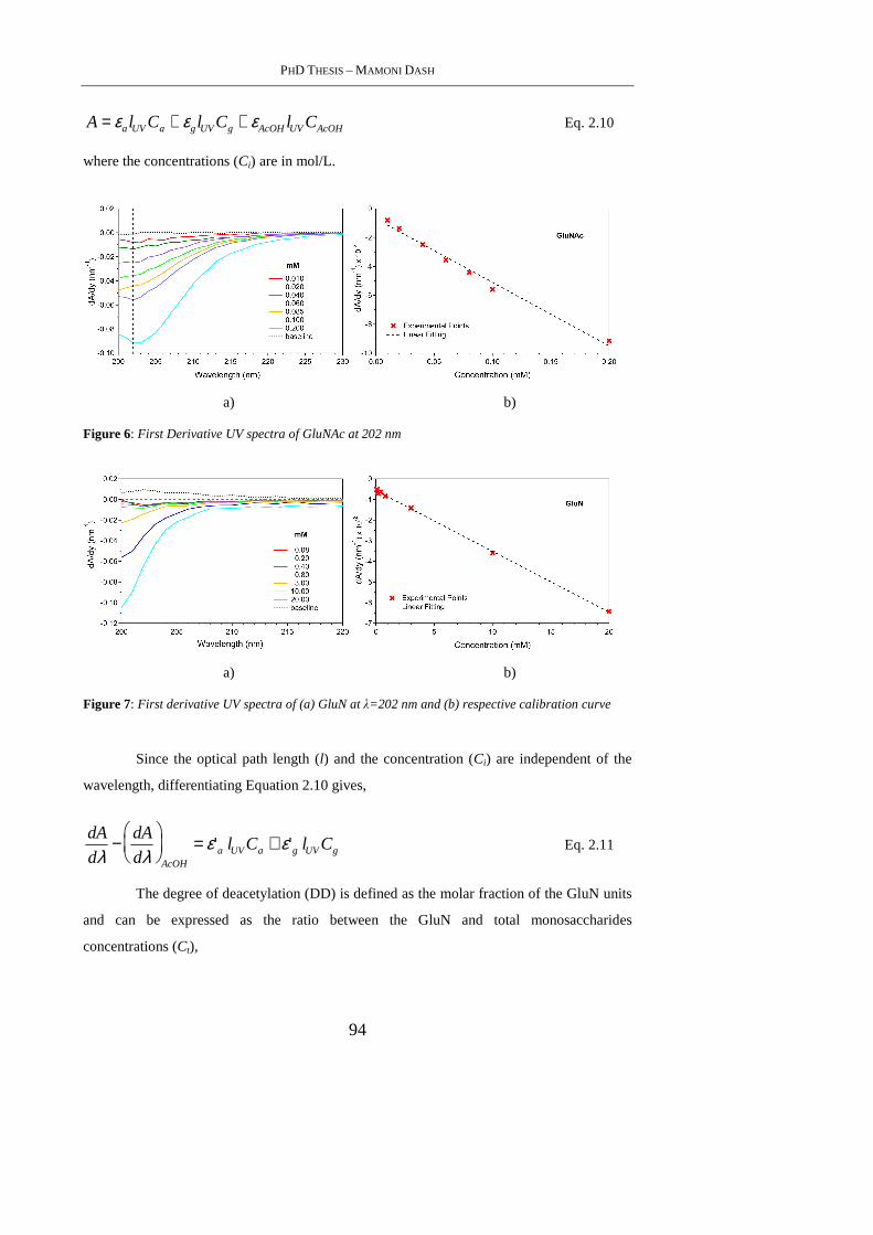
PHD THESIS – MAMONI DASH
94
A = εalUVCa + εglUVCg + εAcOHlUVCAcOH Eq. 2.10
where the concentrations (Ci) are in mol/L.
a) b)
Figure 6: First Derivative UV spectra of GluNAc at 202 nm
a) b)
Figure 7: First derivative UV spectra of (a) GluN at λ=202 nm and (b) respective calibration curve
Since the optical path length (l) and the concentration (Ci) are independent of the
wavelength, differentiating Equation 2.10 gives,
dA
dλ− dA
dλ
AcOH
= ε'a lUVCa + ε'g lUVCg Eq. 2.11
The degree of deacetylation (DD) is defined as the molar fraction of the GluN units
and can be expressed as the ratio between the GluN and total monosaccharides
concentrations (Ct),
CHAPTER 2 – STATISTICAL APPROACH OF CHITIN DEACETYLATION
95
DD =Cg
Ca + Cg
=Cg
Ct
Eq. 2.12
Combining Equations 2.11 and 2.12 and rearranging, it is obtained,
1Ct
dA
dλ− dA
dλ
AcOH
= ε'a lUV − ε'a lUV −ε'g lUV( )DD Eq. 2.13
The Equation 2.13 is the basis of the method proposed herein. It is interesting to
notice that the method developed by Muzzareli and Rocchetti is a particular case of the last
equation [19]. In fact, since εg >> εa, Equation 2.13 can be simplified as follow,
1Ct
dA
dλ− dA
dλ
AcOH
= ε'a lUV − ε'g lUV( )DD Eq. 2.14
Ct within a chitosan sample cannot be achieved without knowing the DD. Thus, it is
more convenient to express the copolymer concentration in terms of solute mass (C t ) in g/L,
which is defined experimentally. These two concentration values are related by the next
Equation,
C tCt
= Ma − (Ma − Mg)DD Eq. 2.15
Where Ma and Mg are the molecular weights of the GluNAc and GluN units within
the copolymer. Combining Equations 2.13 and 2.15, it is obtained,
1
Ct
dA
dλ− dA
dλ
AcOH
=
ε'a lUV − ε'a lUV −ε'g lUV( )DD
Ma − (Ma − Mg)DD Eq. 2.16
Following rearranging, the following results,
DD =1−ε'g lUV −
Mg
Ct
dA
dλ− dA
dλ
AcOH
Ma − Mg
Ct
dA
dλ− dA
dλ
AcOH
− (ε'a lUV −ε'g lUV )
Eq. 2.17
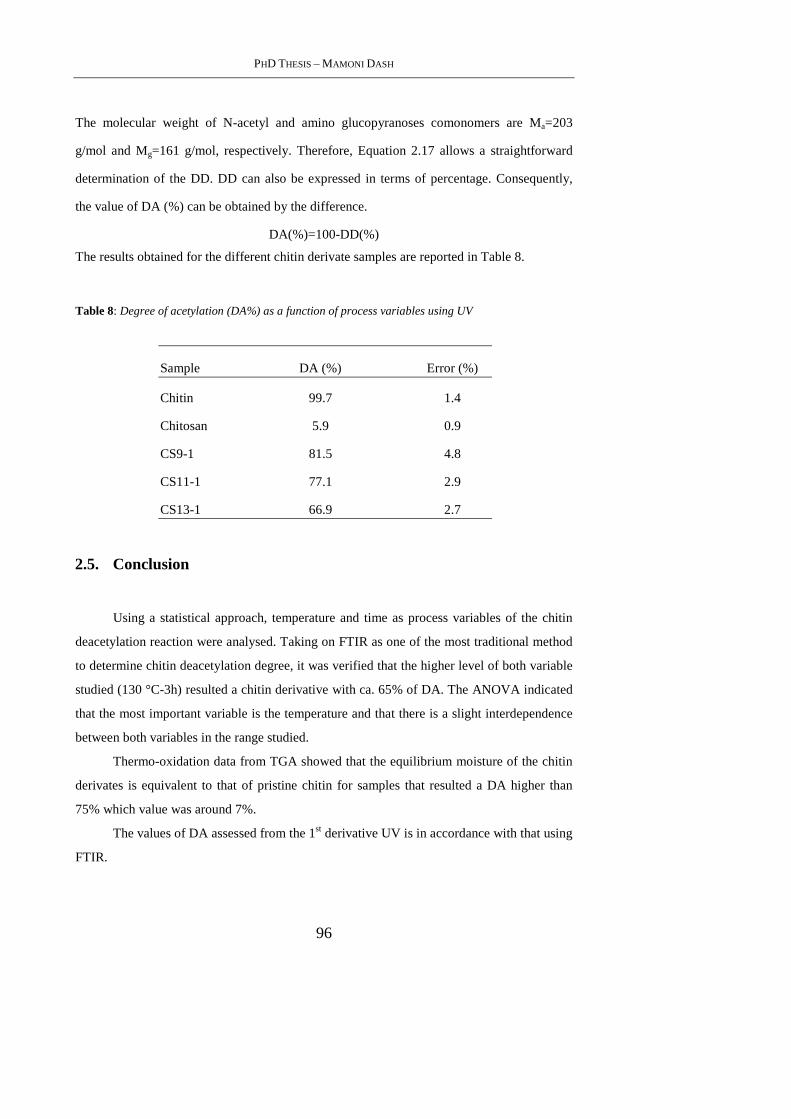
PHD THESIS – MAMONI DASH
96
The molecular weight of N-acetyl and amino glucopyranoses comonomers are Ma=203
g/mol and Mg=161 g/mol, respectively. Therefore, Equation 2.17 allows a straightforward
determination of the DD. DD can also be expressed in terms of percentage. Consequently,
the value of DA (%) can be obtained by the difference.
DA(%)=100-DD(%)
The results obtained for the different chitin derivate samples are reported in Table 8.
Table 8: Degree of acetylation (DA%) as a function of process variables using UV
Sample DA (%) Error (%)
Chitin 99.7 1.4
Chitosan 5.9 0.9
CS9-1 81.5 4.8
CS11-1 77.1 2.9
CS13-1 66.9 2.7
2.5. Conclusion
Using a statistical approach, temperature and time as process variables of the chitin
deacetylation reaction were analysed. Taking on FTIR as one of the most traditional method
to determine chitin deacetylation degree, it was verified that the higher level of both variable
studied (130 °C-3h) resulted a chitin derivative with ca. 65% of DA. The ANOVA indicated
that the most important variable is the temperature and that there is a slight interdependence
between both variables in the range studied.
Thermo-oxidation data from TGA showed that the equilibrium moisture of the chitin
derivates is equivalent to that of pristine chitin for samples that resulted a DA higher than
75% which value was around 7%.
The values of DA assessed from the 1st derivative UV is in accordance with that using
FTIR.

CHAPTER 2 – STATISTICAL APPROACH OF CHITIN DEACETYLATION
97
2.6. References
[1] Kurita, K.; Mar. Biotechnol.; 2006, 203.
[2] Sannan, T.; Kurita, K.; Iwakura, Y., Makromolekulare Chemie-Macromolecular
Chemistry and Physics 1976, 3589.
[3] Wei, W.; Bo, S. Q.; Li, S. Q.; Wen, Q.; Int. J. Biol. Macromol., 1991, 281.
[4] Errington, N.; Harding, S. E.; Varum, K. M.; Illum, L.; Int. J. Biol. Macromol.,1993, 113.
[5] Rinaudo, M.; Milas, M.; Ledung, P., Int. J. Biol. Macromol.,1993, 281.
[6] Varum, K. M.; Ottoy, M. H.; Smidsrod, O.; Carbohydr Polym.,1994, 65.
[7] Zydowicz, N.; Vachoud, L.; Domard, A. In Influence of the acetylation degree of a chitin
gel on its physical and chemical properties, Proceedings of the 1st International Conference
of the European Chitin Society, Lyon.. 1996; A. Domard, C. J., R. Muzzarelli, G. Roberts,
Ed. Jacques Andre Publisher: Lyon.. 1996; pp 262-270.
[8] Shigemasa, Y.; Saito, K.; Sashiwa, H.; Saimoto, H.; Int. J. Biol. Macromol.,1994, 43.
[9] Hutadilok, N.; Mochimasu, T.; Hisamori, H.; Hayashi, K.; Tachibana, H.; Ishii, T.;
Hirano, S.; Carbohydr Polym.,1995, 143.
[10] Nordtveit, R. J.; Varum, K. M.; Smidsrod, O.; Carbohydr Polym., 1996,163.
[11] Peluso, G.; Petillo, O.; Ranieri, M.; Santin, M.; Ambrosio, L.; Calabro, D.; Avallone,
B.; Balsamo, G.; Biomaterials, 1994, 1215.
[12] Curotto, E.; Aros, F.,; Anal. Biochem.,1993, 240.
[13] Ke, H.; Chen, Q.; Huaxue Tongbao 1990, 44.
[14] Rathke, T. D.; Hudson, S. M., J Polym Sci A Polym Chem., 1993, 749.
PHD THESIS – MAMONI DASH
98
[15] Hirai, A.; Odani, H.; Nakajima, A.; Polymer Bulletin ,1991, 87.
[16] Baxter, A.; Dillon, M.; Taylor, K. D. A.; Roberts, G. A. F.; Int. J. Biol. Macromol.
1992, 166.
[17] Domszy, J. G.; Roberts, G. A. F.; Makromolekulare Chemie-Macromolecular
Chemistry and Physics ,1985, 1671.
[18] Sannan, T.; Kurita, K.; Ogura, K.; Iwakura, Y.; Polymer 1978, 458.
[19] Muzzarelli, R. A. A.; Rocchetti, R., Carbohydr Polym., 1985, 461.
[20] Tan, S. C.; Khor, E.; Tan, T. K.; Wong, S. M., Talanta.,1998, 713.
[21] Roberts, G. A. F., Thirty years of progress in chitin and chitosan. Progress in the
Chemistry and Application of Chitin and its Derivatives 2008, XIII, 7-15.
[22] Bristow, J. Chitosan manufacturing process including demineralization, deproteination,
and deacetylation of chitin. WO2009/117499, 20090318., 2009.
[23] Montgomery, D. C., Design and Analysis of Experiments. 3rd ed.; John Wiley & Sons:
New York, 1991.
[24] Kasaai, M. R.; J. Agric. Food Chem., 2009, 1667.
[25] Kasaai, M. R.; Carbohydr Polym., 2008, 497.
[26] Duarte, M. L.; Ferreira, M. C.; Marvao, M. R.; Rocha, J.; Int. J. Biol. Macromol., 2002,
1.
[27] Khan, T. A.; Peh, K. K.; Ch'ng, H. S.; J Pharm Pharm Sci , 2002, 205.
[28] Brugnerotto, J.; Lizardi, J.; Goycoolea, F. M.; Arguelles-Monal, W.; Desbrieres, J.;
Rinaudo, M.;Polymer, 2001, 3569.
[29] Peniche-Covas, C.; Arguellesmonal, W.; Sanroman, J.; Polym. Degrad. Stab., 1993, 21.
CHAPTER 2 – STATISTICAL APPROACH OF CHITIN DEACETYLATION
99
[30] Zohuriaan, M. J.; Shokrolahi, F.; Polymer Testing.,2004, 575.
[31] Alonso, I. G.; Penichecovas, C.; Nieto, J. M.; J Therm Anal Calorim., 1983, 28, (1),
189-193.
[32] Liu, D. S.; Wei, Y. N.; Yao, P. J.; Jiang, L. B.; Carbohydr Polym., 2006, 782.

PHD THESIS – MAMONI DASH
100
101
3. CHITOSAN BASED BEADS FOR CONTROLLED RELEASE OF
PROTEINS
3.1. Abstract
Chitosan is biocompatible polymer of natural origin widely investigated for applications in
drug delivery and regenerative medicine. In this chapter, Chitosan’s capability of forming
water gelling beads in the presence of non-toxic polyanion was exploited for the loading of
two model proteins. Human Serum Albumin (HSA) and porcine trypsin were successfully
loaded into chitosan-tripolyphosphate (TPP) beads. Both proteins were highly incorporated
when the cross-linking process was allowed to occur for 24 h at room temperature (RT). The
release profiles of the two proteins were compared and the faster diffusion of trypsin was
associated to its smaller molecular weight. Moreover, in vitro degradation experiments,
aimed to mimic physiological degradation pattern of the beads displayed a complete
degradation of the material in almost 30 days. Certainly, the preliminary experimental data
acquired in the present work represent a starting study for the promising application of
chitosan-TPP beads for the controlled release of proteins of therapeutic interest.
3.2. Introduction
Chitosan is a cationic polysaccharide composed of β-1,4 linked 2-amino-2-deoxy-
D-glucopyranose (D-glucosamine). In nature it is found in fungi, but it is conventionally
produced by deproteinization, demineralization and deacetylation of chitinous material
which is widely distributed in living organisms (arthropods, fungi, algae, mollusca, etc.) [1].
Chitosan is biocompatible, it does not cause allergic reactions and rejection. Moreover,
chitosan has antacid and antiulcer characteristics, which prevents or weakens drug irritation
in the stomach [2]. Under the action of ferments, in vivo it degrades slowly to harmless
products (amino sugars), which are completely absorbed by the human body. It is known to
possess antimicrobial property and absorbs toxic metals such as mercury, cadmium, lead, etc.
In addition, it has good adhesion properties [3], coagulation ability and immunostimulating
activity [4].
Chitosan is a widely investigated biopolymer, thanks to its gelling capability and
the possibility of applying this natural polymer in regenerative medicine and drug delivery.
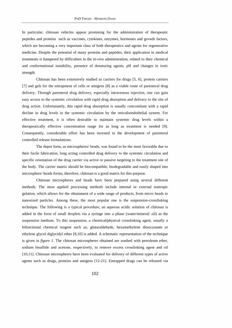
PHD THESIS – MAMONI DASH
102
In particular, chitosan vehicles appear promising for the administration of therapeutic
peptides and proteins such as vaccines, cytokines, enzymes, hormones and growth factors,
which are becoming a very important class of both therapeutics and agents for regenerative
medicine. Despite the potential of many proteins and peptides, their application in medical
treatments is hampered by difficulties in the in-vivo administration, related to their chemical
and conformational instability, presence of denaturing agents, pH and changes in ionic
strength.
Chitosan has been extensively studied as carriers for drugs [5, 6], protein carriers
[7] and gels for the entrapment of cells or antigens [8] as a viable route of parenteral drug
delivery. Through parenteral drug delivery, especially intravenous injection, one can gain
easy access to the systemic circulation with rapid drug absorption and delivery to the site of
drug action. Unfortunately, this rapid drug absorption is usually concomitant with a rapid
decline in drug levels in the systemic circulation by the reticuloendothelial system. For
effective treatment, it is often desirable to maintain systemic drug levels within a
therapeutically effective concentration range for as long as treatment is needed [9].
Consequently, considerable effort has been invested in the development of parenteral
controlled release formulations.
The depot form, as microspheres/ beads, was found to be the most favorable due to
their facile fabrication, long acting controlled drug delivery to the systemic circulation and
specific orientation of the drug carrier via active or passive targeting to the treatment site of
the body. The carrier matrix should be biocompatible, biodegradable and easily shaped into
microsphere/ beads forms, therefore, chitosan is a good matrix for this purpose.
Chitosan microspheres and beads have been prepared using several different
methods. The most applied processing methods include internal or external iontropic
gelation, which allows for the obtainment of a wide range of products, from micro beads to
nanosized particles. Among these, the most popular one is the suspension-crosslinking
technique. The following is a typical procedure; an aqueous acidic solution of chitosan is
added in the form of small droplets via a syringe into a phase (water/mineral/ oil) as the
suspension medium. To this suspension, a chemical/physical crosslinking agent, usually a
bifunctional chemical reagent such as; glutaraldehyde, hexamethylene diisocyanate or
ethylene glycol diglycidyl ether [8,10] is added. A schematic representation of the technique
is given in figure 1. The chitosan microspheres obtained are washed with petroleum ether,
sodium bisulfide and acetone, respectively, to remove excess crosslinking agent and oil
[10,11]. Chitosan microspheres have been evaluated for delivery of different types of active
agents such as drugs, proteins and antigens [12-21]. Entrapped drugs can be released via
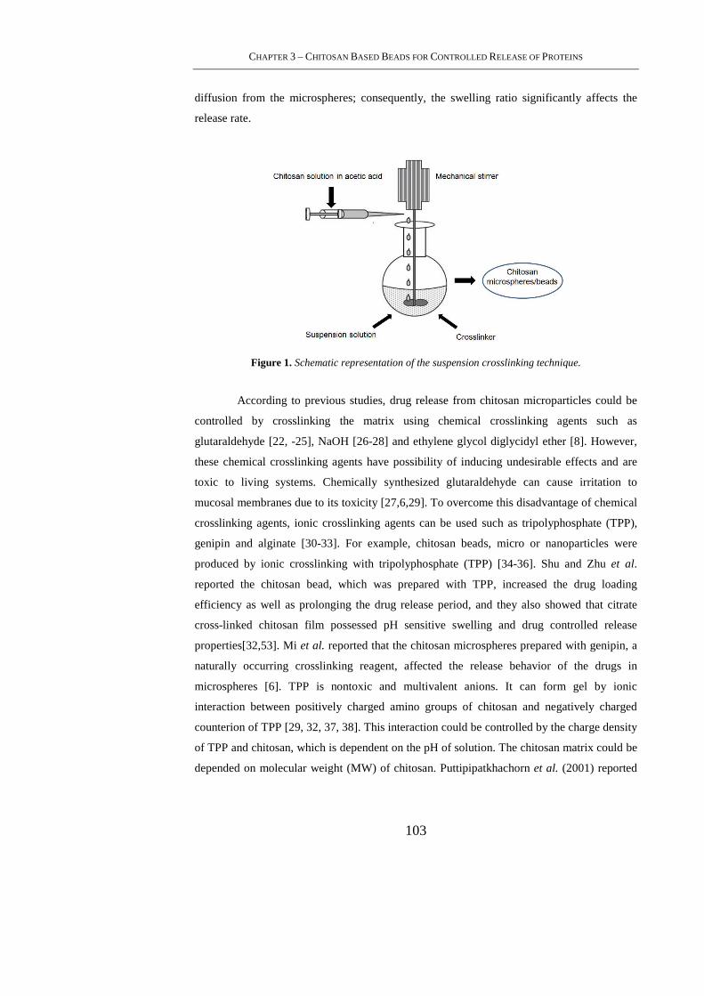
CHAPTER 3 – CHITOSAN BASED BEADS FOR CONTROLLED RELEASE OF PROTEINS
103
diffusion from the microspheres; consequently, the swelling ratio significantly affects the
release rate.
Figure 1. Schematic representation of the suspension crosslinking technique.
According to previous studies, drug release from chitosan microparticles could be
controlled by crosslinking the matrix using chemical crosslinking agents such as
glutaraldehyde [22, -25], NaOH [26-28] and ethylene glycol diglycidyl ether [8]. However,
these chemical crosslinking agents have possibility of inducing undesirable effects and are
toxic to living systems. Chemically synthesized glutaraldehyde can cause irritation to
mucosal membranes due to its toxicity [27,6,29]. To overcome this disadvantage of chemical
crosslinking agents, ionic crosslinking agents can be used such as tripolyphosphate (TPP),
genipin and alginate [30-33]. For example, chitosan beads, micro or nanoparticles were
produced by ionic crosslinking with tripolyphosphate (TPP) [34-36]. Shu and Zhu et al.
reported the chitosan bead, which was prepared with TPP, increased the drug loading
efficiency as well as prolonging the drug release period, and they also showed that citrate
cross-linked chitosan film possessed pH sensitive swelling and drug controlled release
properties[32,53]. Mi et al. reported that the chitosan microspheres prepared with genipin, a
naturally occurring crosslinking reagent, affected the release behavior of the drugs in
microspheres [6]. TPP is nontoxic and multivalent anions. It can form gel by ionic
interaction between positively charged amino groups of chitosan and negatively charged
counterion of TPP [29, 32, 37, 38]. This interaction could be controlled by the charge density
of TPP and chitosan, which is dependent on the pH of solution. The chitosan matrix could be
depended on molecular weight (MW) of chitosan. Puttipipatkhachorn et al. (2001) reported
PHD THESIS – MAMONI DASH
104
that the higher the MW and degree of deacetylation of chitosan, the lower the release rate of
chitosan film [39].
The advantage of iontropic gelation stands in the safeness for the operator, since it
avoids the use of hazardous organic solvents and it is based on the cationic nature of
chitosan, able to crosslink with multivalent anions such as sulfate, citrate, and
tripolyphosphate [40,41]. Tripolyphosphate (TPP) is a non-toxic polyanion which easily
interacts with chitosan and has previously been used for the preparation of chitosan beads,
microspheres and nanoparticles [38].
In this chapter, two model proteins are applied for the preparation of protein loaded chitosan-
TPP beads. HSA has been chosen as middle-size protein model and applied for preliminary
evaluation on loading and release kinetics. Porcine trypsin has been applied as model of
active agent, due to its enzymatic activity it is generally applied for the assessment of activity
maintenance after loading into a polymeric system [42, 43].
3.3. Materials and Methods
3.3.1 Materials
Chitosan and sodium tripolyphosphate(TPP) were purchased from Sigma Aldrich.
Molecular weight was in the range of 190,000 - 375,000 as indicated by the supplier,
viscosity was about 200 cps . Degree of deacetylation (DD) was >85%. All other reagents
and solvents were of reagent grade purity. Human Serum Albumin used as a model protein
and lysozyme (hen egg-white) were purchased from Sigma-Aldrich.
3.3.2 Methods
3.3.2.1 Preparation of crosslinked Chitosan beads
Chitosan powder(0.6 g) was dispersed in 20 mL of water containing 1 (v/v)% acetic
acid. The mixture was stirred and left overnight to prepare dissolved chitosan solution. The
TPP powder was dissolved in distilled water to prepare 1%(w/v) TPP aqueous solutions. The
chitosan solution was dropped through a syringe needle into gently agitated TPP solution and
the gelled spheres formed instantaneously.
CHAPTER 3 – CHITOSAN BASED BEADS FOR CONTROLLED RELEASE OF PROTEINS
105
3.3.2.2 Preparation of protein loaded Chitosan beads
The chitosan and TPP solutions of the same concentrations as above were made.
The model protein HSA was dissolved directly into the TPP solution. The concentration of
the protein in TPP solution is 0.1%. The pH of the TPP solution was maintained at 7. The
solution of TPP and albumin was stirred for 10 min to attain homogeneity. The chitosan
solution was dropped through a syringe needle into gently agitated TPP solution and the
gelled spheres formed instantaneously. The chitosan droplets were stood in the solution for 2
hrs and 24 hrs to cross-link the gel beads and examine the effect of time on crosslinking. To
analyse the effect of temperature on cross linking and encapsulation of the protein the beads
were allowed to crosslink at room temperature as well as at -4°C. After cross linking, the
solidified gel beads were separated and the supernatant collected for further analysis.
Porcine trypsin was loaded under the same conditions of albumin loading, by allowing the
crosslinking at room temperature for 24hrs.
3.3.2.3 Morphological characterization
The surface and cross-sectional morphologies of the dried beads were examined
using scanning electron microscopy (SEM) and Field Emission Microscopy (FEM).
3.3.2.4 Swelling of Chitosan-TPP beads
The water sorption capacity of the beads was determined by swelling the beads in
three media: distilled water, phosphate buffer saline solution (PBS) pH 7.4, cell DMEM
growth media. A known weight (16 mg) of the chitosan beads was placed in different media.
The wet weight of the swollen beads was determined by first blotting the beads with filter
paper to remove the adsorbed water and then weighed immediately on an electronic balance.
The percentage swelling of chitosan beads in the media were calculated by the formula:
BSR% = [(We-Wo)/Wo]*100 (1)
Where BSR is the beads swelling ratio percent at equilibrium. We denote the weight of the
beads at equilibrium swelling and Wo is the initial weight of the beads.
PHD THESIS – MAMONI DASH
106
3.3.2.5 Degradation of Chitosan-TPP beads
The in vitro degradation of chitosan TPP beads was followed in 1ml PBS pH 7.4 at
37 °C containing 1.5 µg/ml lysozyme. The concentration of lysozyme was chosen to
correspond to the concentration in human serum [44]. Briefly, beads of known dry weights
were incubated in the lysozyme solution with gentle mechanical agitation for the period of
study. The lysozyme solution was refreshed daily to ensure continuous enzyme activity [45].
After 7, 14, 21 and 28 days, samples were removed from the medium, rinsed with distilled
water, dried under vacuum and weighed. The extent of in vitro degradation was expressed as
percentage of weight loss of the beads after lysozyme treatment.
3.3.2.6 Evaluation of protein encapsulation efficiency
The supernatants of the drug loaded beads were analysed both by U.V
spectrophotometric method for preliminary protein evaluation and by BCA micro assay kit.
The BCA Micro Assay Kit was used as per the guidelines mentioned on the kit and the
reading was taken at 540nm. All the samples are analysed in triplicate.
The Encapsulation Efficiency (EE%) was calculated from the following expression:
EE%= [Loaded Protein(mg) / Protein Formulation (mg)] *100 (2)
The experiment was performed in two sets: one for 2h cross linking and 24h cross linking
and the other for temperature difference during cross linking process i.e. cross linked at room
temperature and at -4°C.
The Loading(%) was also calculated by using the formula:
Loading (%)=[Loaded Protein(mg)/lyophilised beads (mg)]*100 (3)
3.3.2.7 Protein release studies
Either albumin or trypsin loaded beads were suspended into 50 mL PBS pH 7.4 and
incubated on a shaking water-bath at 37°C. A total of 2 ml supernatant were withdrawn, at
appropriate intervals and protein content was determined by BCA micro assay kit. An equal
volume of the same dissolution medium was added immediately to maintain a constant
volume.
The activity of the released trypsin was also evaluated by a colorimetric assay using
N-α-benzoyl-DL-arginine-4-nitroanilide (BApNA) as synthetic substrate for the enzyme.
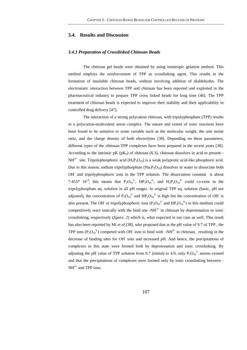
CHAPTER 3 – CHITOSAN BASED BEADS FOR CONTROLLED RELEASE OF PROTEINS
107
3.4. Results and Discussion
3.4.1 Preparation of Crosslinked Chitosan Beads
The chitosan gel beads were obtained by using ionotropic gelation method. This
method employs the reinforcement of TPP as crosslinking agent. This results in the
formation of insoluble chitosan beads, without involving addition of dialdehydes. The
electrostatic interaction between TPP and chitosan has been reported and exploited in the
pharmaceutical industry to prepare TPP cross linked beads for long time [46]. The TPP
treatment of chitosan beads is expected to improve their stability and their applicability in
controlled drug delivery [47].
The interaction of a strong polycation chitosan, with tripolyphosphate (TPP) results
in a polycation-multivalent anion complex. The nature and extent of ionic reactions have
been found to be sensitive to some variable such as the molecular weight, the unit molar
ratio, and the charge density of both electrolytes [38]. Depending on these parameters,
different types of the chitosan-TPP complexes have been prepared in the recent years [38].
According to the intrinsic pK (pK0) of chitosan (6.3), chitosan dissolves in acid to present -
NH3+ site. Tripolyphosphoric acid (H5P3O10) is a weak polyprotic acid-like phosphoric acid.
Due to this reason, sodium tripolyphosphate (Na5P3O10) dissolves in water to dissociate both
OH- and tripolyphosphoric ions in the TPP solution. The dissociation constant is about
7.453* 10-4, this means that P3O105-, HP3O10
4-, and H2P3O103- could co-exist in the
tripolyphosphate aq. solution in all pH ranges. In original TPP aq. solution (basic, pH not
adjusted), the concentration of P3O105- and HP3O10
4- is high but the concentration of OH- is
also present. The OH- or tripolyphosphoric ions (P3O105- and HP3O10
4-) in this medium could
competitively react ionically with the bind site -NH3+ in chitosan by deprotonation or ionic
crosslinking, respectively (figure. 2) which is, what expected in our case as well. This result
has also been reported by Mi et al.[38], who proposed that at the pH value of 9.7 of TPP , the
TPP ions (P3O105-) competed with OH- ions to bind with –NH3+ in chitosan, resulting in the
decrease of binding sites for OH- ions and increased pH. And hence, the precipitations of
complexes in this state were formed both by deprotonation and ionic crosslinking. By
adjusting the pH value of TPP solution from 9.7 (initial) to 4.0, only P3O105- anions existed
and that the precipitations of complexes were formed only by ionic crosslinking between -
NH3+ and TPP ions.
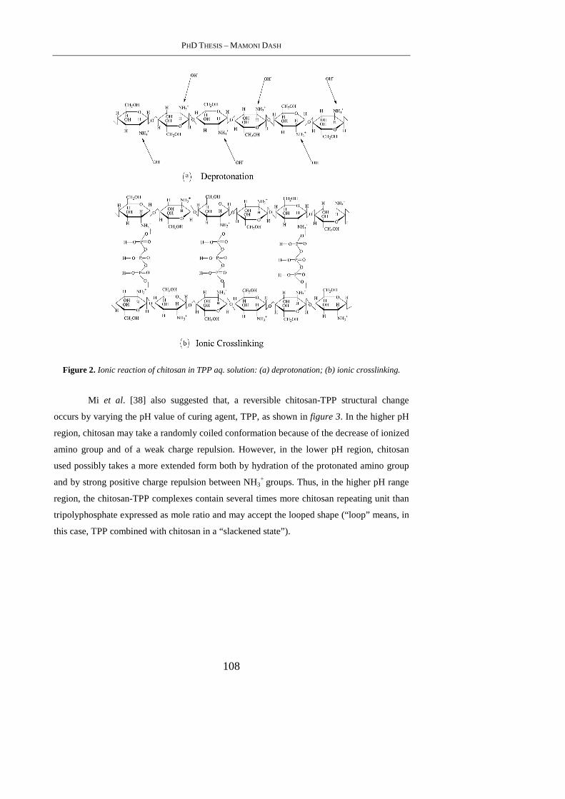
PHD THESIS – MAMONI DASH
108
Figure 2. Ionic reaction of chitosan in TPP aq. solution: (a) deprotonation; (b) ionic crosslinking.
Mi et al. [38] also suggested that, a reversible chitosan-TPP structural change
occurs by varying the pH value of curing agent, TPP, as shown in figure 3. In the higher pH
region, chitosan may take a randomly coiled conformation because of the decrease of ionized
amino group and of a weak charge repulsion. However, in the lower pH region, chitosan
used possibly takes a more extended form both by hydration of the protonated amino group
and by strong positive charge repulsion between NH3+ groups. Thus, in the higher pH range
region, the chitosan-TPP complexes contain several times more chitosan repeating unit than
tripolyphosphate expressed as mole ratio and may accept the looped shape (“loop” means, in
this case, TPP combined with chitosan in a “slackened state”).

CHAPTER 3 – CHITOSAN BASED BEADS FOR CONTROLLED RELEASE OF PROTEINS
109
Figure 3. Ladder-loop transition of chitosan-TPP complex structures: (a) ladder type (b) loop type.
In this state, the ionic reaction of chitosan-TPP complex should be a pH-dependent
coacervation accompanied with slightly ionic-crosslinking. Though according to the
facilitation of ionizing chitosan in lower pH range region, the chains of chitosan accept a
more extended conformation and they form a complex with TPP in a ladder shaped structure.
In this state, chitosan forms complex with multivalent counterions, TPP, through the
formation of intermolecular or intramolecular linkages by ionic interaction. Chitosan-TPP
complexes were formed only by the ionic interaction between the positively charged amino
group and negatively charged counterions, TPP ions. The gelation mechanism of chitosan–
TPP complexes in this state should be fully ionic crosslinking controlled.
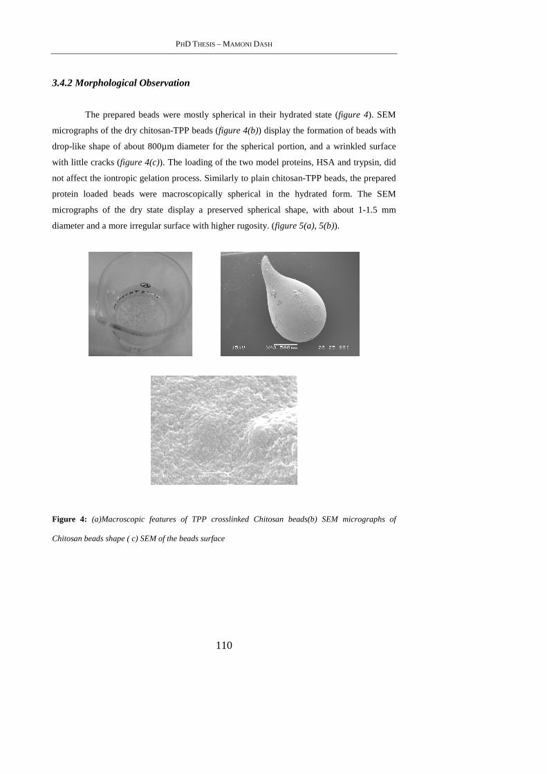
PHD THESIS – MAMONI DASH
110
3.4.2 Morphological Observation
The prepared beads were mostly spherical in their hydrated state (figure 4). SEM
micrographs of the dry chitosan-TPP beads (figure 4(b)) display the formation of beads with
drop-like shape of about 800µm diameter for the spherical portion, and a wrinkled surface
with little cracks (figure 4(c)). The loading of the two model proteins, HSA and trypsin, did
not affect the iontropic gelation process. Similarly to plain chitosan-TPP beads, the prepared
protein loaded beads were macroscopically spherical in the hydrated form. The SEM
micrographs of the dry state display a preserved spherical shape, with about 1-1.5 mm
diameter and a more irregular surface with higher rugosity. (figure 5(a), 5(b)).
Figure 4: (a)Macroscopic features of TPP crosslinked Chitosan beads(b) SEM micrographs of
Chitosan beads shape ( c) SEM of the beads surface
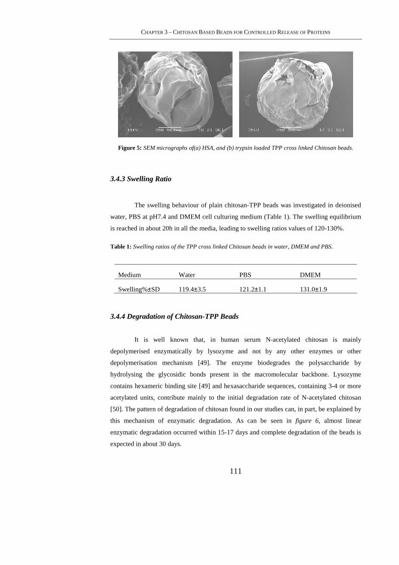
CHAPTER 3 – CHITOSAN BASED BEADS FOR CONTROLLED RELEASE OF PROTEINS
111
Figure 5: SEM micrographs of(a) HSA, and (b) trypsin loaded TPP cross linked Chitosan beads.
3.4.3 Swelling Ratio
The swelling behaviour of plain chitosan-TPP beads was investigated in deionised
water, PBS at pH7.4 and DMEM cell culturing medium (Table 1). The swelling equilibrium
is reached in about 20h in all the media, leading to swelling ratios values of 120-130%.
Table 1: Swelling ratios of the TPP cross linked Chitosan beads in water, DMEM and PBS.
Medium Water PBS DMEM
Swelling%±SD 119.4±3.5 121.2±1.1 131.0±1.9
3.4.4 Degradation of Chitosan-TPP Beads
It is well known that, in human serum N-acetylated chitosan is mainly
depolymerised enzymatically by lysozyme and not by any other enzymes or other
depolymerisation mechanism [49]. The enzyme biodegrades the polysaccharide by
hydrolysing the glycosidic bonds present in the macromolecular backbone. Lysozyme
contains hexameric binding site [49] and hexasaccharide sequences, containing 3-4 or more
acetylated units, contribute mainly to the initial degradation rate of N-acetylated chitosan
[50]. The pattern of degradation of chitosan found in our studies can, in part, be explained by
this mechanism of enzymatic degradation. As can be seen in figure 6, almost linear
enzymatic degradation occurred within 15-17 days and complete degradation of the beads is
expected in about 30 days.
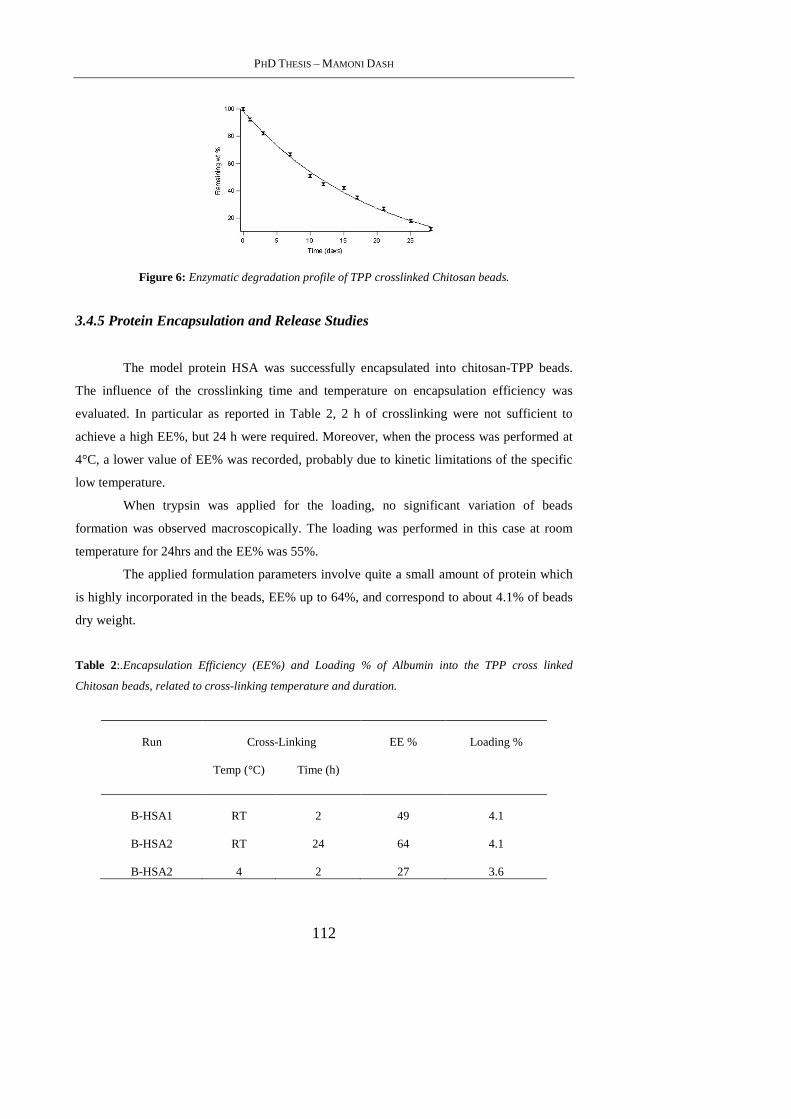
PHD THESIS – MAMONI DASH
112
Figure 6: Enzymatic degradation profile of TPP crosslinked Chitosan beads.
3.4.5 Protein Encapsulation and Release Studies
The model protein HSA was successfully encapsulated into chitosan-TPP beads.
The influence of the crosslinking time and temperature on encapsulation efficiency was
evaluated. In particular as reported in Table 2, 2 h of crosslinking were not sufficient to
achieve a high EE%, but 24 h were required. Moreover, when the process was performed at
4°C, a lower value of EE% was recorded, probably due to kinetic limitations of the specific
low temperature.
When trypsin was applied for the loading, no significant variation of beads
formation was observed macroscopically. The loading was performed in this case at room
temperature for 24hrs and the EE% was 55%.
The applied formulation parameters involve quite a small amount of protein which
is highly incorporated in the beads, EE% up to 64%, and correspond to about 4.1% of beads
dry weight.
Table 2:.Encapsulation Efficiency (EE%) and Loading % of Albumin into the TPP cross linked
Chitosan beads, related to cross-linking temperature and duration.
Run Cross-Linking EE % Loading %
Temp (°C) Time (h)
B-HSA1 RT 2 49 4.1
B-HSA2 RT 24 64 4.1
B-HSA2 4 2 27 3.6
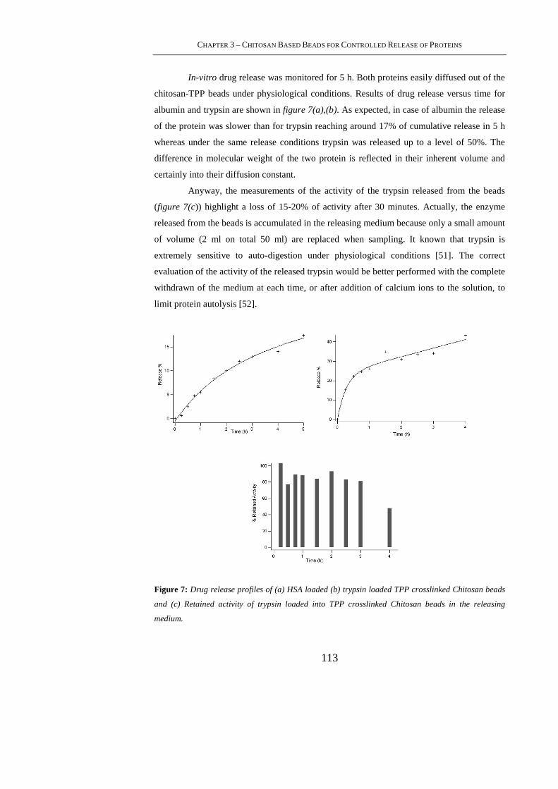
CHAPTER 3 – CHITOSAN BASED BEADS FOR CONTROLLED RELEASE OF PROTEINS
113
In-vitro drug release was monitored for 5 h. Both proteins easily diffused out of the
chitosan-TPP beads under physiological conditions. Results of drug release versus time for
albumin and trypsin are shown in figure 7(a),(b). As expected, in case of albumin the release
of the protein was slower than for trypsin reaching around 17% of cumulative release in 5 h
whereas under the same release conditions trypsin was released up to a level of 50%. The
difference in molecular weight of the two protein is reflected in their inherent volume and
certainly into their diffusion constant.
Anyway, the measurements of the activity of the trypsin released from the beads
(figure 7(c)) highlight a loss of 15-20% of activity after 30 minutes. Actually, the enzyme
released from the beads is accumulated in the releasing medium because only a small amount
of volume (2 ml on total 50 ml) are replaced when sampling. It known that trypsin is
extremely sensitive to auto-digestion under physiological conditions [51]. The correct
evaluation of the activity of the released trypsin would be better performed with the complete
withdrawn of the medium at each time, or after addition of calcium ions to the solution, to
limit protein autolysis [52].
Figure 7: Drug release profiles of (a) HSA loaded (b) trypsin loaded TPP crosslinked Chitosan beads
and (c) Retained activity of trypsin loaded into TPP crosslinked Chitosan beads in the releasing
medium.
PHD THESIS – MAMONI DASH
114
3.5. Conclusion
In this work, the conditions for the preparation of protein loaded TPP crosslinked
chitosan beads were optimized for the achievement of high protein loading. The activity of
the model enzyme was not significantly affected by the process and the observed reduction
of activity of the released protein is mostly associated with trypsin autolysis. Under
physiological conditions the release profiles of the loaded proteins seem related to their
molecular weight and the complete degradation of the TPP crosslinked chitosan beads under
lysozyme digestion occurs in 30 days. The present work represent a starting study for the
promising application of chitosan-TPP beads for the controlled release of proteins of
therauputic interest. Forthcoming studies will be focussed on the reduction of bead size to
micro-nanostructures with the same properties of the prepared beads, but with the ability to
reach all body areas after conventional administration.
3.6. References
[1].Steinbüchel, A (Ed.) Biopolymers, Volume 5-6. Polysaccharides I and II Vandamme EJ,
De Baets S and Steinbüchel A. WILEY-VCH Verlag GmbH, Weinheim, Germany (2002).
[2]. Gupta, K.C., Ravi Kumar, M.N.V.; Polym. Int., 2000, 141.
[3]. Bravo-Osuna, I., Vauthier, C., Farabollini, A., Palmieri, G.F., Ponchel, G.; Biomaterials,
2007, 2233.
[4]. Muzzarelli, R.A.A., Muzzarelli, C.; Adv Polymer Sci, 2005 ,151.
[5]. Bayomi, M.A., Al-Suwayeh, S.A., El-Helw, A.M., Mesnad, A.F.; Pharmaceutica Acta
Helvetiae, 1998, 187.
[6]. Mi, F.L., Sung, H.W., Shyu, S.S.; J. Appl. Polym. Sci. 2001, 1700.
[7]. Calvo, P., Remun˜a´n-Lo´pez, C., Vila-jato, J.L., Alonso, M.J.; J. Appl. Polym. Sci.
1997, 125.
[8]. Mi, F.L., Shyu, S.S., Chen, C.T., Schoung, J.Y.; Biomaterials, 1999, 1603
CHAPTER 3 – CHITOSAN BASED BEADS FOR CONTROLLED RELEASE OF PROTEINS
115
[9]. 38. Chein, Y.W. (1992). Novel Drug Delivery Systems, 2nd edn, revised and expanded,
p. 381, Marcel Dekker Inc., New York.
[10]. Denkbas, E.B., Odabasc, M.; J. Appl. Poly. Sci., 2000, 1637.
[11]. Denkbas, E.B., Odabasc, M., Kılıçay, E. , Özdemir, N.; J. Appl. Poly. Sci., 2002,3035.
[12]. Denkbas, E.B., Seyyal, M., Pisckin, E.; J. Microencapsulation, 1999, 741.
[13]. Gupta, K.C. , Ravi Kumar, M.N.V.; Biomaterials, 2000, 1115.
[14]. Hata, H., Onishi, H. and Machida, Y. Biomaterials, 2000, 1779.
[15]. Mi, F.L., Lin, Y.M., Wu, Y.B., Shyu, S.S. , Tsai, Y.H. Biomaterials, 2002, 3257.
[16]. Shi, X.Y., Tan, T.W.; Biomaterials, 2002, 4469 .
[17]. Mi, F.L., Tan, Y.C., Liang, H.F., Sung, H.W.; Biomaterials, 2002,181.
[18]. Takechi, M., Miyamoto, Y., Momota, Y., Yuasa, T., Tatehara, S., Nagayama, M.,
Ishikawa, K. , Suzuki, K. ; J. Mater. Sci. Mater. Med., 2002, 973.
[19].Vandenberg, G.W., Drolet, C., Scott, S.L. , Noue, J.D.; J. Control. Release, 2001, 297.
[20].Vila, A., Sanchez, A., Toblo, M., Calvo, P. , Alonso, M.J.; J. Control. Release, 2002,15.
[21]. Zhou, S.B., Deng, X.M., Li, X.H.; J. Control. Release, 2001, 27.
[22]. Jameela, S.R., Jayakrishnan, A.; Biomaterials, 1995,769.
[23]. Genta, I., Perugini, P., Conti, B., Pabanetto, F.; Int. J. Pharm. 1997, 237.
[24].Genta, I., Costatini, M., Asti, A., Conti, B., Montanari, L.; Carbohyd. Polym. 1998, 81.
PHD THESIS – MAMONI DASH
116
[25]. Blanco, M.D., Go´mez, C., Olmo, R., Mun˜ iz, E., Teijio´n, J.M.; Int. J. Pharm. 2000,
29.
[26]. Chandy, T., Sharma, C.P.; Biomaterials, 1996, 61.
[27]. Lim, L.Y., Wan, L.S.C., Thai, P.Y.; Drug Dev. Ind. Pharm. 1997, 981.
[28]. Vasudev, S.C., Chandy, T., Sharma, C.P.; Biomaterials, 1997, 375.
[29].Shu, X.Z., Zhu, K.J.; J. Microencapsulation, 2001, 237.
[30]. Ko, J.A., Park, H.J., Hwang, S.J., Park, J.B. , Lee, J.S.; Int. J. of Pharm., 2002, 165.
[31]. Tan, T., Hu, B., Jin, X. and Zhang, M.; J. Bioact. Comp. Pol., 2003, 207.
[32]. Shu, X.Z., Zhu, K.J.; Int. J. Pharm., 2000, 51.
[33]. Mi, F.L., Sung, H.W., Shyu, S.S.; J. Appl. Polym. Sci., 2001, 1700.
[34]. Bodmeier, R., Oh, K.H., Pramar, Y.; Drug Dev. Ind. Pharm. 1989, 1475.
[35]. Shiraishi, S., Imai, T., Otagiri, M.; J. Control. Release. 1993, 217.
[36].Calvo, P., Remun˜a´n-Lo´pez, C., Vila-jato, J.L., Alonso, M.J.;. J. Appl. Polym. Sci.,
1997, 125.
[37].Aral, C., Akbug˘a, J.; Int. J. Pharm. 1998, 9.
[38]. Mi, F.L., Shyu, S.S., Lee, S.T., Wong, T.B.; J. Polym. Sci: Polym. Phys. 1999b, 1551.
[39]. Puttipipatkhachorn, S., Nunthanid, J., Yamamoto, K., Peck, G.E.; J. Control. Release.
2001, 143.
[40]. Agnihotri, S.A., Mallikarjuna, N.N., Aminabhavi, T.M.; J. Control Release, 2004, 5 .
CHAPTER 3 – CHITOSAN BASED BEADS FOR CONTROLLED RELEASE OF PROTEINS
117
[41]. Denkbas, E.B., Ottenbrite, R.M; J Bioact Compat Polym ,2006, 351.
[42]. Chiellini, F., Bartoli, C., Dinucci, D., Piras, A.M., Anderson, R., Croucher, T.; Int J
Pharm, 2007, 90.
[43]. Piras, A.M., Chiellini, F., Fiumi, C., Bartoli, C., Chiellini, E., Fiorentino, B., Farina, C.;
Int J Pharm, 2008, 260.
[44]. Porstmann, B. Jung, K., Schmechta, H., Evers, U., Pergande, M., Porstmann, T.,
Kramm, H.J., Krause, H.; Clin Biochem, 1989, 349.
[45]. Masuda, T., Ueno, Y., Kitabatake, N.; J Agric Food Chem , 2001, 4937.
[46]. Shu, X.Z., Zhu, K.J.; Int J Pharm, 2002, 217.
[47]. Anal, A.K., Stevens, W.F., Remunan-Lopez, C.; Int J Pharm,2006,166.
[48]. Varum, K.M., Myhr, M.M., Hjerde, R.J.N.O.; Carbohydr Res, 1997, 99.
[49]. Pangburn SH, Trescony PV, Heller J, Biomaterials, 1982, 105.
[50]. Nordtveit, R.J., Varum, K.M., Smidsrod, O.; Carbohydr Polym, 1994, 253.
[51]. Li, X. F., Nie, X., Tang, J.G.; Biochem. Biophys. Res. Commun., 1998, 235
[52]. Vajda, T., Garai A.; J Inorg Biochem , 1981, 307.
[53]. Shu, X.Z., Zhu, K.J., Song, W.; Int. J. Pharm. 2001, 19.

PHD THESIS – MAMONI DASH
118
119
4. HYBRID NANOPARTICLES BASED ON CHITOSAN AND
POLY(METHACRYLOYLGLYCYLGLYCINE)
4.1. Abstract
A novel polyelectrolyte complex nanoparticles were prepared based on chitosan and
poly(methacryloylglycylglycine) [poly(MAGlyGly)]. The physical-chemical properties of
the complexes were investigated by means of dynamic light scattering, scanning electron
microscopy, zeta potential and X-ray photo electron spectroscopy (XPS). The results
indicated that the addition of chitosan into MAGlyGly in DMSO and polymerized
subsequently resulted in the formation of nanoparticles in the size range of 100-120 nm with
proper chitosan and MAGlyGly weight ratios. Variation of the ratio of the different
components revealed that the formation of the nanoparticles depended strongly on the ratio
of chitosan and MAGlyGly. The particles also showed difference in size and morphology
before and after polymerization. Zeta potential studies highlighted a positive surface charge
and the results were well supported by XPS analysis.
4.2. Introduction
Nanotechnology is of great interest in most fields, since it allows manipulating
matter at the nanoscale level [1,2] and tailoring final product properties. Among the various
tools used in nanotechnology, nanoparticles represent a widely studied area. Nanoparticle
synthesis is currently intensely researched due to its wide variety of potential applications,
including food processing [3,4] and biomedical [5], optical [6], and electronic devices [7].
The use of natural polysaccharides in the preparation of nanoparticles has attracted attention
[8-11] due to their biocompatibility, biodegradability, and hydrophilicity, which are
favorable characteristics in various applications. Chitosan nanoparticles [12,13] stand out
due to their unique properties. Chitosan is a polysaccharide derived from chitin, which may
be obtained from crustaceans, insects, fungi, etc. [14]. Several appealing properties have
been reported, such as film-forming ability, gelatinous characteristics, bioadhesion, and skin
penetration-enhancing effects, which may be explained by the opening of tight epithelial cell
junctions. Due to its polymeric cationic characteristics, Chitosan may interact with
negatively charged molecules and polymers [15]. In detail, chitosan is a weak base with a
pKa value of the D-glucosamine residue of about 6.2-7 and therefore is insoluble at neutral
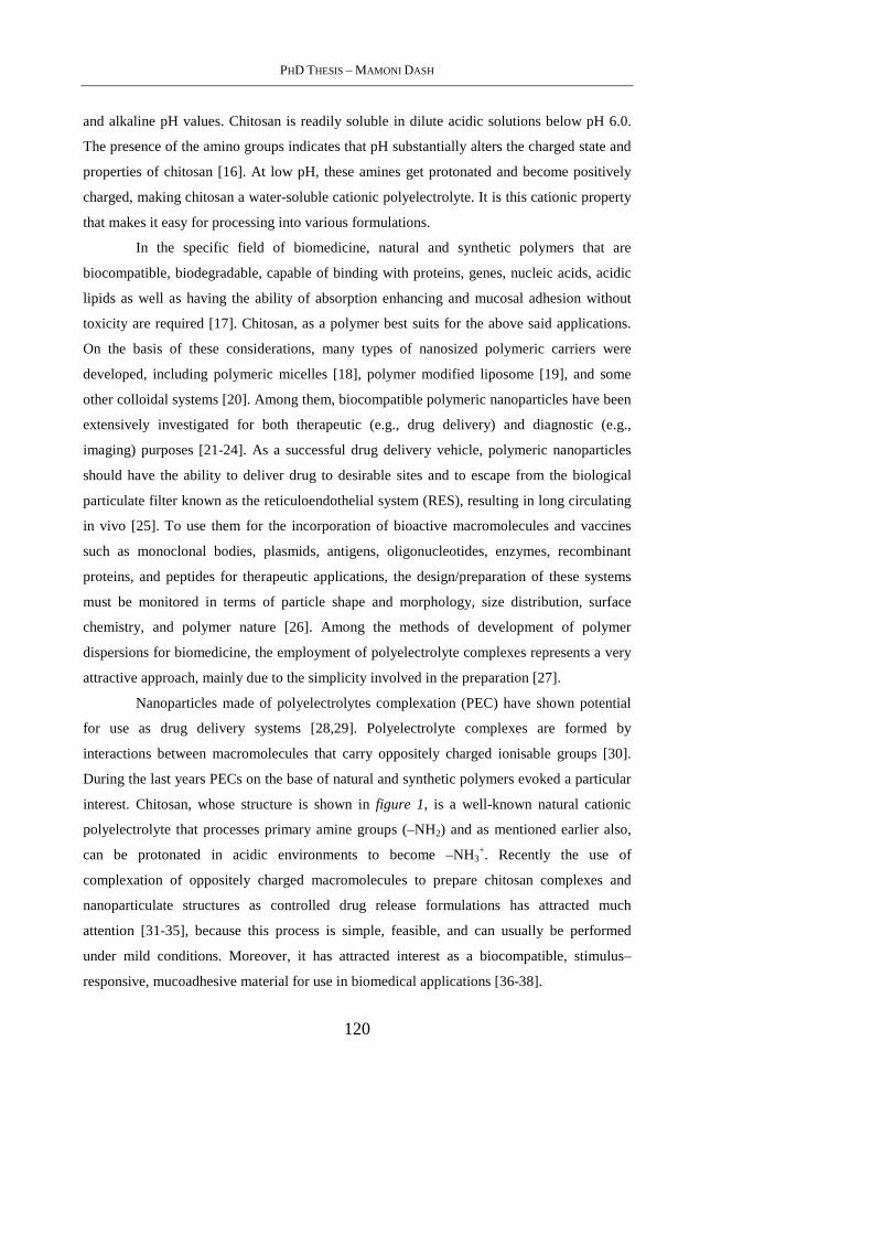
PHD THESIS – MAMONI DASH
120
and alkaline pH values. Chitosan is readily soluble in dilute acidic solutions below pH 6.0.
The presence of the amino groups indicates that pH substantially alters the charged state and
properties of chitosan [16]. At low pH, these amines get protonated and become positively
charged, making chitosan a water-soluble cationic polyelectrolyte. It is this cationic property
that makes it easy for processing into various formulations.
In the specific field of biomedicine, natural and synthetic polymers that are
biocompatible, biodegradable, capable of binding with proteins, genes, nucleic acids, acidic
lipids as well as having the ability of absorption enhancing and mucosal adhesion without
toxicity are required [17]. Chitosan, as a polymer best suits for the above said applications.
On the basis of these considerations, many types of nanosized polymeric carriers were
developed, including polymeric micelles [18], polymer modified liposome [19], and some
other colloidal systems [20]. Among them, biocompatible polymeric nanoparticles have been
extensively investigated for both therapeutic (e.g., drug delivery) and diagnostic (e.g.,
imaging) purposes [21-24]. As a successful drug delivery vehicle, polymeric nanoparticles
should have the ability to deliver drug to desirable sites and to escape from the biological
particulate filter known as the reticuloendothelial system (RES), resulting in long circulating
in vivo [25]. To use them for the incorporation of bioactive macromolecules and vaccines
such as monoclonal bodies, plasmids, antigens, oligonucleotides, enzymes, recombinant
proteins, and peptides for therapeutic applications, the design/preparation of these systems
must be monitored in terms of particle shape and morphology, size distribution, surface
chemistry, and polymer nature [26]. Among the methods of development of polymer
dispersions for biomedicine, the employment of polyelectrolyte complexes represents a very
attractive approach, mainly due to the simplicity involved in the preparation [27].
Nanoparticles made of polyelectrolytes complexation (PEC) have shown potential
for use as drug delivery systems [28,29]. Polyelectrolyte complexes are formed by
interactions between macromolecules that carry oppositely charged ionisable groups [30].
During the last years PECs on the base of natural and synthetic polymers evoked a particular
interest. Chitosan, whose structure is shown in figure 1, is a well-known natural cationic
polyelectrolyte that processes primary amine groups (–NH2) and as mentioned earlier also,
can be protonated in acidic environments to become –NH3+. Recently the use of
complexation of oppositely charged macromolecules to prepare chitosan complexes and
nanoparticulate structures as controlled drug release formulations has attracted much
attention [31-35], because this process is simple, feasible, and can usually be performed
under mild conditions. Moreover, it has attracted interest as a biocompatible, stimulus–
responsive, mucoadhesive material for use in biomedical applications [36-38].
CHAPTER 4 – HYBRID NANOPARTICLES BASED ON CHITOSAN AND POLY(METHACRYLOYLGLYCYLGLYCINE )
121
Figure1: Chitosan
These complexes made up of polymeric systems can be used to physically trap an
antitumor agent and release it in a sustained form directly at the tumor site [39,40]. They also
allow for controlling the release pattern of drug and sustaining drug levels for a long time by
appropriately selecting the polymeric carrier [41].
Water-soluble polymers such as N-(2-hydroxypropyl)-methacrylamide (HPMA) co-
polymers are a class of synthetic polymers that are frequently employed as drug carriers
because of their ability to improve the solubility of hydrophobic compounds, reduce non-
specific toxicity, and increase the therapeutic index of low molecular weight anticancer
drugs [42]. Anticancer drugs chemically bound to water-soluble polymeric carriers such as
HPMA co-polymers (polymeric prodrugs) have exhibited decreased systemic toxicity, as a
result of the altered biodistribution of polymer-bound drugs as compared to free drugs [43].
Several drug-polymer conjugates based on HPMA co-polymers have been studied clinically.
A doxorubicin-(HPMA co-polymer) conjugate, known as PK1, was the first drug-polymer
conjugate to enter clinical trials [44]. Targeted HPMA co-polymer-bound doxorubicin
conjugates have previously been shown to have a significant anti-tumor effect in vitro and in
vivo [45,46] and have shown greater potency than free doxorubicin in the treatment of
ovarian cancer in vivo and in vitro [47]. Recently authors have reported the first endocrine-
chemotherapy combination in the form of the model compound HPMA co-polymer-
aminoglutethimide doxorubicin [48]. In our laboratory, nanoparticles based on bioeliminable
co-polymers poly(methacryloylglycylglycine-OHx-co-hydroxypropylmethacrylamidey) were
prepared and loaded with HSA as model drug [49].
Based on this approach methacryloylglycylglycine (MAGlyGly) was prepared and
used for preparing nanoparticles employing compelexation with chitosan. MAGlyGly is a
biocompatible synthetic polyelectrolyte with polyanionic character, its wide applicability as
a co-monomer in the field of drug delivery is impressive. It has carboxylic groups which
ionize to become COO- groups that can effectively react with the NH3+ groups of chitosan to
form a polyelectrolyte complex. Various reaction parameters have been optimized to form
PHD THESIS – MAMONI DASH
122
nanoparticles with this PEC’s. When ionized, both polyelectrolytes have intrinsic biological
properties. In parallel, the production of nanoparticles through in situ polymerization appears
to be an interesting route as well. In the present work, the possibility to prepare chitosan
based nanoparticles by the polymerization of the anionic monomer MAGlyGly was
investigated and the effect of subsequent polymerization observed. Hence, the objective of
the present study was to optimise the preparative conditions of chitosanx-poly(MAGlyGly) y
nanoparticles and to establish the interaction between the two using various techniques.
4.3. Materials and Methods
4.3.1 Materials
Glycyl-glycine (GlyGly), methacryloyl chloride, ammonium persulphate
[(NH4)2S2O8], sodium metabisulfite (Na2S2O5) and Chitosan (Mw = 71.3 kDa, degree of
deacetylation 93%) were purchased from Sigma-Aldrich and used as received.
4.3.2 Methods
4.3.2.1 Synthesis of MAGlyGly
GlyGly (one equivalent) was added to a solution of sodium hydroxide (one
equivalent) in water (19,8 w/v). Methacryloyl chloride was cooled to 0°C (one equivalent)
and to it a solution of sodium hydroxide (one equivalent) in water (19,8 w/v) was added
dropwise and simultaneously. The reaction mixture was stirred at room temperature for two
hours than acidified with concentrated hydrochloric acid to pH 2. The crystal that
precipitated from solution was isolated by recrystallization from 1:1 water/ethanol solution.
The crystalline white monomer was dried in vacuum. The obtained yield was 50%.
FT–IR (KBr): ν = 3380-3100 (ν OH, NH), 1740 (ν C=O carboxylic), 1647.4 (ν C=O amide I
band), 1605.9 (ν C=C), 1540.4 (δ N-H and ν C-N amide II band), 1431 (ν C-O and O-H
carboxylic) and 1337.9 cm-1 (δ CH3). 1H NMR (200 MHz, DMSO-d6): δ (ppm) 1,8(s, 3H), 3,8(m, 4H,), 5,3 (s, 1H,), 5,7 (s, 1H,)
and 8,2 ppm (m, 2H).

CHAPTER 4 – HYBRID NANOPARTICLES BASED ON CHITOSAN AND POLY(METHACRYLOYLGLYCYLGLYCINE )
123
4.3.2.2 Preparation of Chitosan-MAGlyGly nanoparticles [CSx-(MAGlyGly)y]
Nanoparticles were prepared for 50:50 (w/w) and 25:75 (w/w) ratio of chitosan and
MAGlyGly respectively. Data relevant to individual experiments are summarized in Table 1,
whereas a typical experiment is described as follows.
10 mg of chitosan was dissolved in a solution of 25,5 mg of MAGlyGly in 5 mL of 1:9
dimethyl sulphoxide/water mixture for two hours under magnetic stirring. With the slow
dissolution of chitosan in the solution mixture, opalescence was observed. After two hours
under magnetic stirring the suspension was stored at 4°C and submitted to further
investigations.
After the dissolution of chitosan in the MAGlyGly solution, the suspension was stored at
4°C.
4.3.2.3 Preparation of Chitosan-polymerized(MAGlyGly) nanoparticles [CSx-
poly(MAGlyGly)y]
CSx-poly(MAGlyGly)y nanoparticles were obtained by polymerizing MAGlyGly in
DMSO solution containing chitosan as described below. Nanoparticles were prepared for
both the ratios of 50:50 (w/w) and 25:75 (w/w) of chitosan and MAGlyGly respectively also
in this case. Data relevant to individual experiments are summarized in table 1, whereas a
typical experiment is described as follows.
10 mg of chitosan was dissolved in a solution of 25,5 mg of MAGlyGly in 5 mL of
1:9 dimethyl sulphoxide/water mixture for two hours under magnetic stirring. After the
dissolution, 10 µL each of 1% w/v [(NH4)2S2O8] and 1% w/v (Na2S2O5) solutions were
added to the chitosan-MAGlyGly formulation and the mixture was maintained under stirring
at 70°C for an additional hour then cooled in an ice bath for 20 minutes. The nanoparticle
suspension was stored at 4°C.
For purification, the nanoparticle suspension was placed in a polypropylene conical
tube and centrifuged at 8000 g for 45 min at 25 °C by using an ALC PK121 R refrigerated
centrifuge. The resulting pellet was suspended in distilled water.
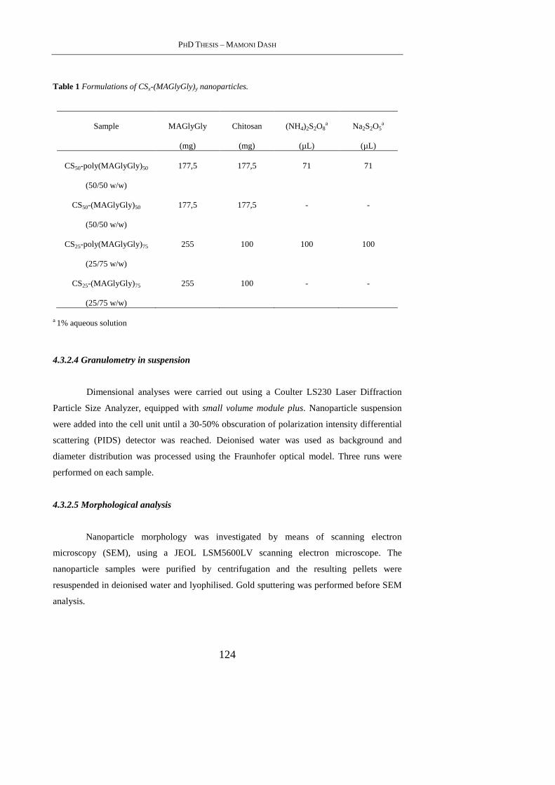
PHD THESIS – MAMONI DASH
124
Table 1 Formulations of CSx-(MAGlyGly)y nanoparticles.
Sample MAGlyGly
(mg)
Chitosan
(mg)
(NH4)2S2O8a
(µL)
Na2S2O5a
(µL)
CS50-poly(MAGlyGly)50
(50/50 w/w)
177,5 177,5 71 71
CS50-(MAGlyGly) 50
(50/50 w/w)
177,5 177,5 - -
CS25-poly(MAGlyGly)75
(25/75 w/w)
255 100 100 100
CS25-(MAGlyGly) 75
(25/75 w/w)
255 100 - -
a 1% aqueous solution
4.3.2.4 Granulometry in suspension
Dimensional analyses were carried out using a Coulter LS230 Laser Diffraction
Particle Size Analyzer, equipped with small volume module plus. Nanoparticle suspension
were added into the cell unit until a 30-50% obscuration of polarization intensity differential
scattering (PIDS) detector was reached. Deionised water was used as background and
diameter distribution was processed using the Fraunhofer optical model. Three runs were
performed on each sample.
4.3.2.5 Morphological analysis
Nanoparticle morphology was investigated by means of scanning electron
microscopy (SEM), using a JEOL LSM5600LV scanning electron microscope. The
nanoparticle samples were purified by centrifugation and the resulting pellets were
resuspended in deionised water and lyophilised. Gold sputtering was performed before SEM
analysis.
CHAPTER 4 – HYBRID NANOPARTICLES BASED ON CHITOSAN AND POLY(METHACRYLOYLGLYCYLGLYCINE )
125
4.3.2.6 Spectroscopic analysis
Infrared (FT-IR) spectra were recorded on liquid films and KBr pellets by using a
Jasco FT–IR 410 spectrophotometer.
Nuclear Magnetic Resonance (NMR) spectra were recorded on 5–10% (w/v)
solutions, in deuterated solvents, at 25 °C by using a Varian Gemini 200 spectrometer and
tetramethylsilane (TMS) as internal standard. 1H–NMR spectra were recorded at 200 MHz,
using the following spectral conditions: 3 KHz spectral width, 30 ° impulse, 2s acquisition
time, 1–16 transients. Chemical shifts (δ) are reported in ppm and referred to
tetramethylsilane as standard. Peak multiplicity is denoted by the following: s = singlet, d =
doublet, dd = double doublet, t = triplet, m = multiplet.
CSx-poly(MAGlyGly)y and CSx-(MAGlyGly) y nanoparticles were pressed into KBr pellets
(1:100 copolymer/KBr ratio) and the FT-IR spectra were recorded by using the same, Jasco
FT-IR 410 spectrophotometer
4.3.2.7 Surface chemical characterization
X-ray Photoelectron Spectroscopy (XPS) was used to assess the surface chemical
composition of CSx-(MAGlyGly) y and of CSx-poly(MAGlyGly)y nanoparticles. Surface
chemical characterization of the nanomaterials was performed using a Thermo VG Theta
probe spectrometer equipped with a microspot monochromatized Al Kα source and a flood
gun combined with an argon gun for compensation of electrostatic charging of samples.
The Al Kα line (1486.6 eV) was used throughout the work and the base pressure of
the instrument was 10-9 mbar. Survey and high-resolution spectra were acquired in fixed
analyzer transmission mode with pass energies of 150 and 50 eV, respectively. Data analysis
was performed using the Avantage software package, which consists of a non-linear least-
squares fitting program. The surface composition was determined by using the
manufacturer's sensitivity factors.
The fractional concentration of a particular element X (% X) was computed using
the following equation:
% X = [ (Ix/fx)/ Σ(I i/f i) ]·100
where Ii and fi are the integrated peak areas of each of the n detected elements and their
sensitivity factors, respectively. The values of binding energies (BE–eV) were taken
relatively to the binding energy of C1s-electrons of hydrocarbon contaminants on the sample
PHD THESIS – MAMONI DASH
126
surface (from an adventitious carbon), which is accepted to be equal to 285.0 eV. The curve
fitting process was done by imposing the same peak full width at half maximum (FWHM) to
the all N1s peaks.
4.3.2.8 Zeta potential analysis
Zeta potential analyses were performed on CSx-(MAGlyGly) y and CSx-
poly(MAGlyGly)y samples purified by centrifugation and resuspended in saline (NaCl 0.9%)
so that the final concentration of nanoparticles was about 0.1 mg / ml and the pH around 3.5-
4. The tests were performed using Beckman Coulter DELSA 440SX at 25 ° C with a
maximum deviation of 0.4 °C between the ends of the cell and setting constant values of
current. Statistically significant results were obtained from the average of 3 replicates for
each matrix used.
4.3.2.9 Thermal analysis
Thermal Gravimetric Analysis (TGA) measurements of were carried out on 5-10
mg nanoparticles samples in the 30–900°C temperature range in a nitrogen atmosphere at 10
°C/min heated with a Thermogravimetric Analyzer TGA Q500.
4.4. Results And Discussion
4.4.1 Preparation & Characterization of MAGlyGly
A similar amidation reaction between methacryloyl chloride and glycylglycine,
conducted in a basic aqueous media with NaOH, led to the formation of the monomer,
methacryloylglycylglycine-OH (MAGlyGly). The system was obtained pure after
recrystallization from methanol with yield of 50% (Scheme 1).

CHAPTER 4 – HYBRID NANOPARTICLES BASED ON CHITOSAN AND POLY(METHACRYLOYLGLYCYLGLYCINE )
127
Scheme 1: Synthesis of MAGlyGly.
The formation of the product was confirmed by spectroscopic characterizations (figure 2).
Figure 2 Spectroscopic characterization of MAGlyGly: (a) 1H- NMR spectrum, (b) FT-IR spectrum.
4.4.2 Synthesis & Characterization of [CSx-(MAGlyGly)y] and [CSx-
poly(MAGlyGly)y] nanoparticles
In this study, a novel nanoparticle system composed of chitosan and
poly(MAGlyGly) was prepared with a simple and mild method under magnetic stirring.
Briefly, chitosan was added to a solution of MAGlyGly in DMSO under stirring for two
hours. This technique is promising because the nanoparticles can be prepared under mild
conditions without using harmful solvents. It is well known that organic solvents may cause
denaturation of peptide or protein drugs that are unstable and sensitive to their environments
[50]. The prepared nanoparticles are intended to be used for drug delivery applications and
hence such mild conditions are congenial. In our case, when chitosan is added to MAGlyGly
solution, it goes into a polyelectrolyte form, which establishes electrostatic interactions with
MAGlyGly and leads to the formation of CSx-MAGlyGly y nanoparticles. This phenomenon
is observed immediately by the appearance of opalescence. It is important to point out that
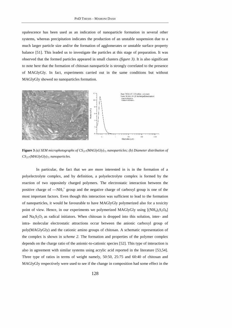
PHD THESIS – MAMONI DASH
128
opalescence has been used as an indication of nanoparticle formation in several other
systems, whereas precipitation indicates the production of an unstable suspension due to a
much larger particle size and/or the formation of agglomerates or unstable surface property
balance [51]. This leaded us to investigate the particles at this stage of preparation. It was
observed that the formed particles appeared in small clusters (figure 3). It is also significant
to note here that the formation of chitosan nanoparticle is strongly correlated to the presence
of MAGlyGly. In fact, experiments carried out in the same conditions but without
MAGlyGly showed no nanoparticles formation.
Figure 3 (a) SEM microphotographs of CS25-(MAGlyGly)75 nanoparticles; (b) Diameter distribution of
CS25-(MAGlyGly)75 nanoparticles.
In particular, the fact that we are more interested in is in the formation of a
polyelectrolyte complex, and by definition, a polyelectrolyte complex is formed by the
reaction of two oppositely charged polymers. The electrostatic interaction between the
positive charge of —NH3+ group and the negative charge of carboxyl group is one of the
most important factors. Even though this interaction was sufficient to lead to the formation
of nanoparticles, it would be favourable to have MAGlyGly polymerized also for a toxicity
point of view. Hence, in our experiments we polymerized MAGlyGly using [(NH4)2S2O8]
and Na2S2O5 as radical initiators. When chitosan is dropped into this solution, inter- and
intra- molecular electrostatic attractions occur between the anionic carboxyl group of
poly(MAGlyGly) and the cationic amino groups of chitosan. A schematic representation of
the complex is shown in scheme 2. The formation and properties of the polymer complex
depends on the charge ratio of the anionic-to-cationic species [52]. This type of interaction is
also in agreement with similar systems using acrylic acid reported in the literature [53,54].
Three type of ratios in terms of weight namely, 50:50, 25:75 and 60:40 of chitosan and
MAGlyGly respectively were used to see if the change in composition had some effect in the
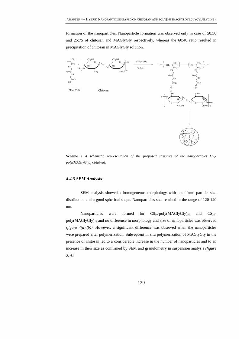
CHAPTER 4 – HYBRID NANOPARTICLES BASED ON CHITOSAN AND POLY(METHACRYLOYLGLYCYLGLYCINE )
129
formation of the nanoparticles. Nanoparticle formation was observed only in case of 50:50
and 25:75 of chitosan and MAGlyGly respectively, whereas the 60:40 ratio resulted in
precipitation of chitosan in MAGlyGly solution.
Scheme 2 A schematic representation of the proposed structure of the nanoparticles CSx-
poly(MAGlyGly)y obtained.
4.4.3 SEM Analysis
SEM analysis showed a homogeneous morphology with a uniform particle size
distribution and a good spherical shape. Nanoparticles size resulted in the range of 120-140
nm.
Nanoparticles were formed for CS50-poly(MAGlyGly)50 and CS25-
poly(MAGlyGly)75 and no difference in morphology and size of nanoparticles was observed
(figure 4(a),(b)). However, a significant difference was observed when the nanoparticles
were prepared after polymerization. Subsequent in situ polymerization of MAGlyGly in the
presence of chitosan led to a considerable increase in the number of nanoparticles and to an
increase in their size as confirmed by SEM and granulometry in suspension analysis (figure
3, 4).
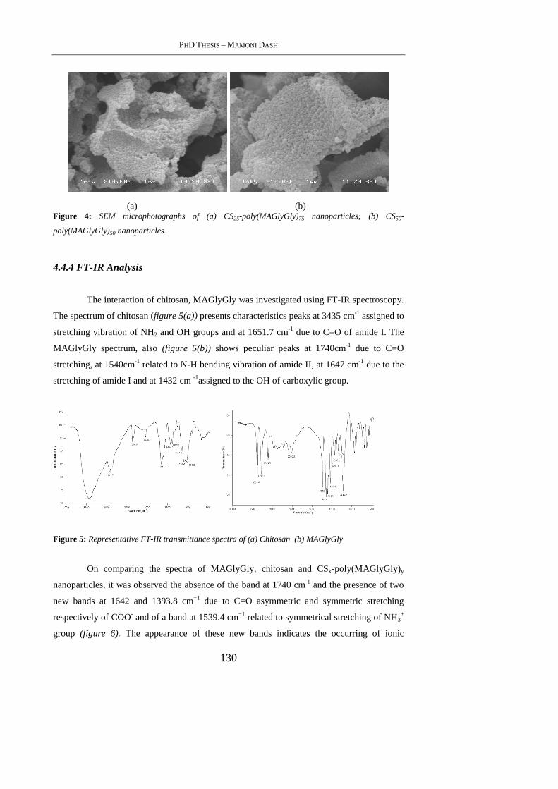
PHD THESIS – MAMONI DASH
130
(a) (b) Figure 4: SEM microphotographs of (a) CS25-poly(MAGlyGly)75 nanoparticles; (b) CS50-
poly(MAGlyGly)50 nanoparticles.
4.4.4 FT-IR Analysis
The interaction of chitosan, MAGlyGly was investigated using FT-IR spectroscopy.
The spectrum of chitosan (figure 5(a)) presents characteristics peaks at 3435 cm-1 assigned to
stretching vibration of NH2 and OH groups and at 1651.7 cm-1 due to C=O of amide I. The
MAGlyGly spectrum, also (figure 5(b)) shows peculiar peaks at 1740cm-1 due to C=O
stretching, at 1540cm-1 related to N-H bending vibration of amide II, at 1647 cm-1 due to the
stretching of amide I and at 1432 cm -1assigned to the OH of carboxylic group.
Figure 5: Representative FT-IR transmittance spectra of (a) Chitosan (b) MAGlyGly
On comparing the spectra of MAGlyGly, chitosan and CSx-poly(MAGlyGly)y
nanoparticles, it was observed the absence of the band at 1740 cm-1 and the presence of two
new bands at 1642 and 1393.8 cm−1 due to C=O asymmetric and symmetric stretching
respectively of COO- and of a band at 1539.4 cm−1 related to symmetrical stretching of NH3+
group (figure 6). The appearance of these new bands indicates the occurring of ionic
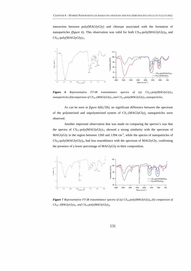
CHAPTER 4 – HYBRID NANOPARTICLES BASED ON CHITOSAN AND POLY(METHACRYLOYLGLYCYLGLYCINE )
131
interaction between poly(MAGlyGly) and chitosan associated with the formation of
nanoparticles (figure 6). This observation was valid for both CS50-poly(MAGlyGly)50 and
CS25-poly(MAGlyGly)75
Figure 6 Representative FT-IR transmittance spectra of (a) CS25-poly(MAGlyGly)75
nanoparticles.(b)comparison of CS25-(MAGlyGly)75 and CS25-poly(MAGlyGly)75 nanoparticles.
As can be seen in figure 6(b),7(b), no significant difference between the spectrum
of the polymerized and unpolymerised system of CSx-(MAGlyGly) y nanoparticles were
observed.
Another important observation that was made on comparing the spectra’s was that
the spectra of CS25-poly(MAGlyGly)75 showed a strong similarity with the spectrum of
MAGlyGly in the region between 1260 and 1394 cm-1, while the spectra of nanoparticles of
CS50-poly(MAGlyGly)50 had less resemblance with the spectrum of MAGlyGly, confirming
the presence of a lower percentage of MAGlyGly in their composition.
Figure 7 Representative FT-IR transmittance spectra of (a) CS50-poly(MAGlyGly)50 (b) comparison of
CS50- (MAGlyGly)50 and CS50-poly(MAGlyGly)50
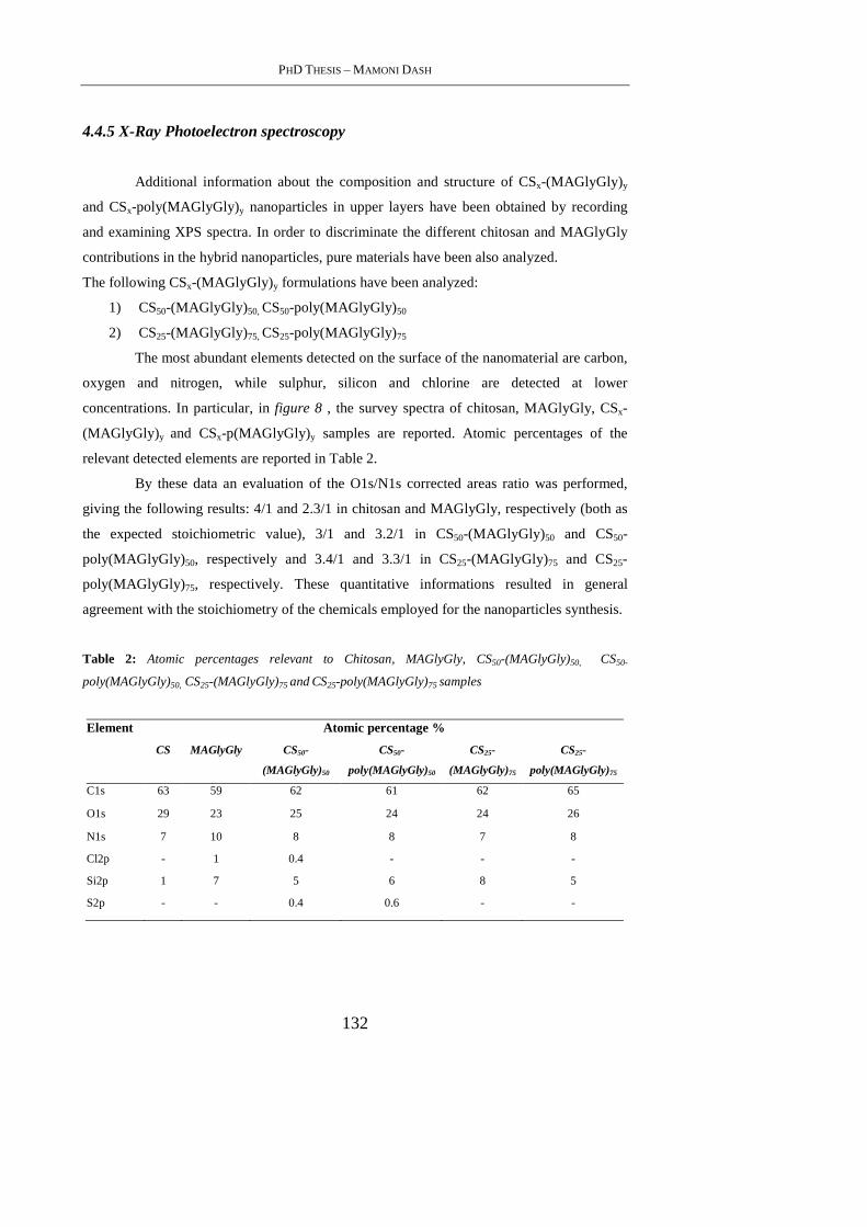
PHD THESIS – MAMONI DASH
132
4.4.5 X-Ray Photoelectron spectroscopy
Additional information about the composition and structure of CSx-(MAGlyGly) y
and CSx-poly(MAGlyGly)y nanoparticles in upper layers have been obtained by recording
and examining XPS spectra. In order to discriminate the different chitosan and MAGlyGly
contributions in the hybrid nanoparticles, pure materials have been also analyzed.
The following CSx-(MAGlyGly) y formulations have been analyzed:
1) CS50-(MAGlyGly) 50, CS50-poly(MAGlyGly)50
2) CS25-(MAGlyGly) 75, CS25-poly(MAGlyGly)75
The most abundant elements detected on the surface of the nanomaterial are carbon,
oxygen and nitrogen, while sulphur, silicon and chlorine are detected at lower
concentrations. In particular, in figure 8 , the survey spectra of chitosan, MAGlyGly, CSx-
(MAGlyGly) y and CSx-p(MAGlyGly)y samples are reported. Atomic percentages of the
relevant detected elements are reported in Table 2.
By these data an evaluation of the O1s/N1s corrected areas ratio was performed,
giving the following results: 4/1 and 2.3/1 in chitosan and MAGlyGly, respectively (both as
the expected stoichiometric value), 3/1 and 3.2/1 in CS50-(MAGlyGly) 50 and CS50-
poly(MAGlyGly)50, respectively and 3.4/1 and 3.3/1 in CS25-(MAGlyGly) 75 and CS25-
poly(MAGlyGly)75, respectively. These quantitative informations resulted in general
agreement with the stoichiometry of the chemicals employed for the nanoparticles synthesis.
Table 2: Atomic percentages relevant to Chitosan, MAGlyGly, CS50-(MAGlyGly)50, CS50-
poly(MAGlyGly)50, CS25-(MAGlyGly)75 and CS25-poly(MAGlyGly)75 samples
Element Atomic percentage %
CS MAGlyGly CS50-
(MAGlyGly)50
CS50-
poly(MAGlyGly)50
CS25-
(MAGlyGly)75
CS25-
poly(MAGlyGly)75
C1s 63 59 62 61 62 65
O1s 29 23 25 24 24 26
N1s 7 10 8 8 7 8
Cl2p - 1 0.4 - - -
Si2p 1 7 5 6 8 5
S2p - - 0.4 0.6 - -
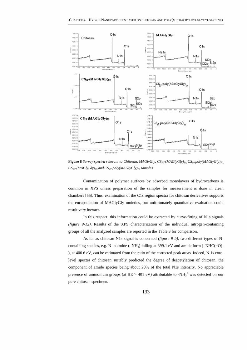
CHAPTER 4 – HYBRID NANOPARTICLES BASED ON CHITOSAN AND POLY(METHACRYLOYLGLYCYLGLYCINE )
133
Figure 8 Survey spectra relevant to Chitosan, MAGlyGly, CS50-(MAGlyGly)50, CS50 poly(MAGlyGly)50,
CS25-(MAGlyGly)75 and CS25-poly(MAGlyGly)75 samples
Contamination of polymer surfaces by adsorbed monolayers of hydrocarbons is
common in XPS unless preparation of the samples for measurement is done in clean
chambers [55]. Thus, examination of the C1s region spectra for chitosan derivatives supports
the encapsulation of MAGlyGly moieties, but unfortunately quantitative evaluation could
result very inexact.
In this respect, this information could be extracted by curve-fitting of N1s signals
(figure 9-12). Results of the XPS characterization of the individual nitrogen-containing
groups of all the analyzed samples are reported in the Table 3 for comparison.
As far as chitosan N1s signal is concerned (figure 9 b), two different types of N-
containing species, e.g. N in amine (–NH2) falling at 399.1 eV and amide form (–NHC(=O)-
), at 400.6 eV, can be estimated from the ratio of the corrected peak areas. Indeed, N 1s core-
level spectra of chitosan suitably predicted the degree of deacetylation of chitosan, the
component of amide species being about 20% of the total N1s intensity. No appreciable
presence of ammonium groups (at BE > 401 eV) attributable to -NH3+ was detected on our
pure chitosan specimen.
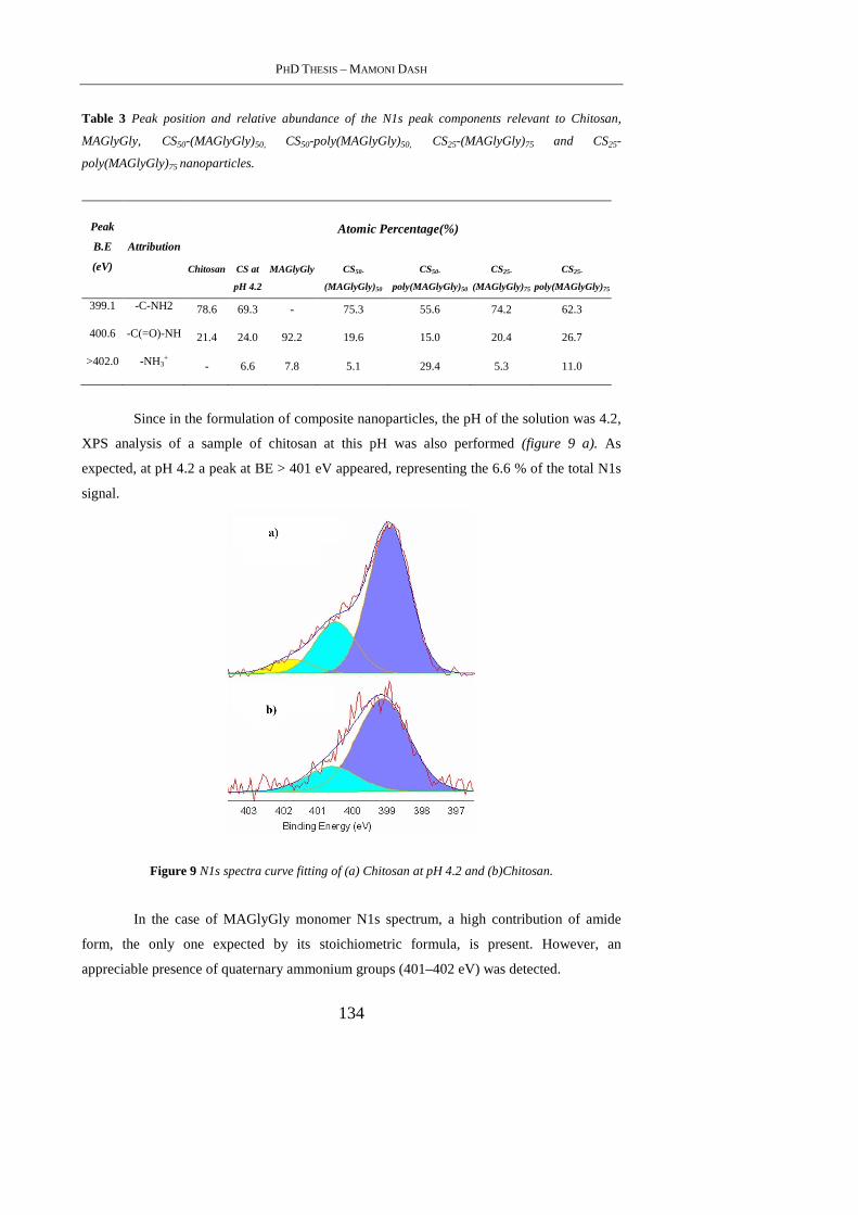
PHD THESIS – MAMONI DASH
134
Table 3 Peak position and relative abundance of the N1s peak components relevant to Chitosan,
MAGlyGly, CS50-(MAGlyGly)50, CS50-poly(MAGlyGly)50, CS25-(MAGlyGly)75 and CS25-
poly(MAGlyGly)75 nanoparticles.
Peak
B.E
(eV)
Attribution
Atomic Percentage(%)
Chitosan CS at
pH 4.2
MAGlyGly CS50-
(MAGlyGly)50
CS50-
poly(MAGlyGly)50
CS25-
(MAGlyGly)75
CS25-
poly(MAGlyGly)75
399.1 -C-NH2 78.6 69.3 - 75.3 55.6 74.2 62.3
400.6 -C(=O)-NH 21.4 24.0 92.2 19.6 15.0 20.4 26.7
>402.0 -NH3+ - 6.6 7.8 5.1 29.4 5.3 11.0
Since in the formulation of composite nanoparticles, the pH of the solution was 4.2,
XPS analysis of a sample of chitosan at this pH was also performed (figure 9 a). As
expected, at pH 4.2 a peak at BE > 401 eV appeared, representing the 6.6 % of the total N1s
signal.
Figure 9 N1s spectra curve fitting of (a) Chitosan at pH 4.2 and (b)Chitosan.
In the case of MAGlyGly monomer N1s spectrum, a high contribution of amide
form, the only one expected by its stoichiometric formula, is present. However, an
appreciable presence of quaternary ammonium groups (401–402 eV) was detected.
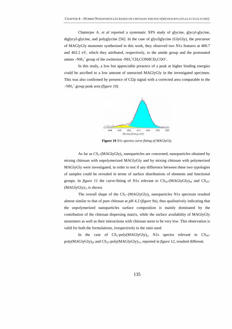
CHAPTER 4 – HYBRID NANOPARTICLES BASED ON CHITOSAN AND POLY(METHACRYLOYLGLYCYLGLYCINE )
135
Chatterjee A. et al reported a systematic XPS study of glycine, glycyl-glycine,
diglycyl-glycine, and polyglycine [56]. In the case of glycilglycine (GlyGly), the precursor
of MAGlyGly monomer synthesised in this work, they observed two N1s features at 400.7
and 402.2 eV, which they attributed, respectively, to the amide group and the protonated
amino –NH3+ group of the zwitterion -NH3
+CH2CONHCH2COO−.
In this study, a low but appreciable presence of a peak at higher binding energies
could be ascribed to a low amount of unreacted MAGlyGly in the investigated specimen.
This was also confirmed by presence of Cl2p signal with a corrected area comparable to the
–NH3+ group peak area (figure 10).
Figure 10 N1s spectra curve fitting of MAGlyGly.
As far as CSx-(MAGlyGly) y nanoparticles are concerned, nanoparticles obtained by
mixing chitosan with unpolymerized MAGlyGly and by mixing chitosan with polymerized
MAGlyGly were investigated, in order to test if any difference between these two typologies
of samples could be revealed in terms of surface distributions of elements and functional
groups. In figure 11 the curve-fitting of N1s relevant to CS50-(MAGlyGly) 50 and CS25-
(MAGlyGly) 75 is shown.
The overall shape of the CSx–(MAGlyGly)y nanoparticles N1s spectrum resulted
almost similar to that of pure chitosan at pH 4.2 (figure 9a), thus qualitatively indicating that
the unpolymerized nanoparticles surface composition is mainly dominated by the
contribution of the chitosan dispersing matrix, while the surface availability of MAGlyGly
monomers as well as their interactions with chitosan seem to be very low. This observation is
valid for both the formulations, irrespectively to the ratio used.
In the case of CSx-poly(MAGlyGly)y, N1s spectra relevant to CS50-
poly(MAGlyGly)50 and CS25-poly(MAGlyGly)75, reported in figure 12, resulted different.
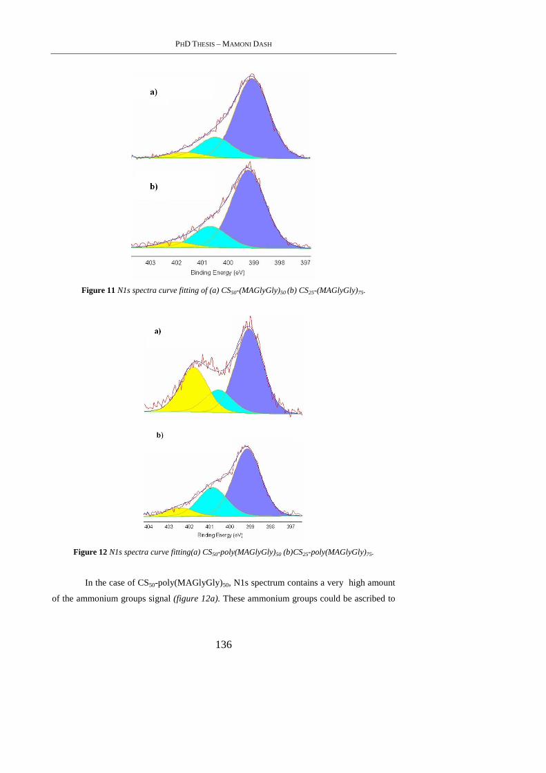
PHD THESIS – MAMONI DASH
136
Figure 11 N1s spectra curve fitting of (a) CS50-(MAGlyGly)50 (b) CS25-(MAGlyGly)75.
Figure 12 N1s spectra curve fitting(a) CS50-poly(MAGlyGly)50 (b)CS25-poly(MAGlyGly)75.
In the case of CS50-poly(MAGlyGly)50, N1s spectrum contains a very high amount
of the ammonium groups signal (figure 12a). These ammonium groups could be ascribed to
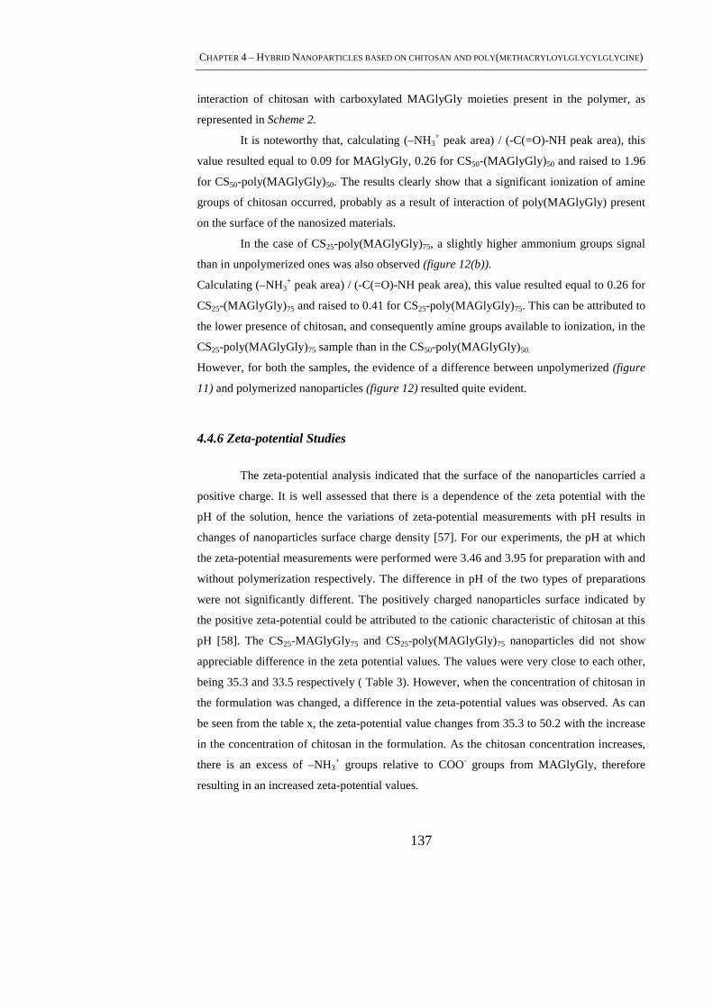
CHAPTER 4 – HYBRID NANOPARTICLES BASED ON CHITOSAN AND POLY(METHACRYLOYLGLYCYLGLYCINE )
137
interaction of chitosan with carboxylated MAGlyGly moieties present in the polymer, as
represented in Scheme 2.
It is noteworthy that, calculating (–NH3+ peak area) / (-C(=O)-NH peak area), this
value resulted equal to 0.09 for MAGlyGly, 0.26 for CS50-(MAGlyGly) 50 and raised to 1.96
for CS50-poly(MAGlyGly)50. The results clearly show that a significant ionization of amine
groups of chitosan occurred, probably as a result of interaction of poly(MAGlyGly) present
on the surface of the nanosized materials.
In the case of CS25-poly(MAGlyGly)75, a slightly higher ammonium groups signal
than in unpolymerized ones was also observed (figure 12(b)).
Calculating (–NH3+ peak area) / (-C(=O)-NH peak area), this value resulted equal to 0.26 for
CS25-(MAGlyGly) 75 and raised to 0.41 for CS25-poly(MAGlyGly)75. This can be attributed to
the lower presence of chitosan, and consequently amine groups available to ionization, in the
CS25-poly(MAGlyGly)75 sample than in the CS50-poly(MAGlyGly)50.
However, for both the samples, the evidence of a difference between unpolymerized (figure
11) and polymerized nanoparticles (figure 12) resulted quite evident.
4.4.6 Zeta-potential Studies
The zeta-potential analysis indicated that the surface of the nanoparticles carried a
positive charge. It is well assessed that there is a dependence of the zeta potential with the
pH of the solution, hence the variations of zeta-potential measurements with pH results in
changes of nanoparticles surface charge density [57]. For our experiments, the pH at which
the zeta-potential measurements were performed were 3.46 and 3.95 for preparation with and
without polymerization respectively. The difference in pH of the two types of preparations
were not significantly different. The positively charged nanoparticles surface indicated by
the positive zeta-potential could be attributed to the cationic characteristic of chitosan at this
pH [58]. The CS25-MAGlyGly75 and CS25-poly(MAGlyGly)75 nanoparticles did not show
appreciable difference in the zeta potential values. The values were very close to each other,
being 35.3 and 33.5 respectively ( Table 3). However, when the concentration of chitosan in
the formulation was changed, a difference in the zeta-potential values was observed. As can
be seen from the table x, the zeta-potential value changes from 35.3 to 50.2 with the increase
in the concentration of chitosan in the formulation. As the chitosan concentration increases,
there is an excess of –NH3+ groups relative to COO- groups from MAGlyGly, therefore
resulting in an increased zeta-potential values.
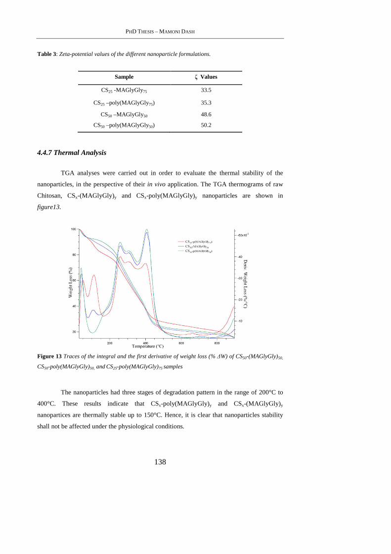
PHD THESIS – MAMONI DASH
138
Table 3: Zeta-potential values of the different nanoparticle formulations.
Sample ζ Values
CS25 -MAGlyGly75 33.5
CS25 –poly(MAGlyGly75) 35.3
CS50 –MAGlyGly50 48.6
CS50 –poly(MAGlyGly50) 50.2
4.4.7 Thermal Analysis
TGA analyses were carried out in order to evaluate the thermal stability of the
nanoparticles, in the perspective of their in vivo application. The TGA thermograms of raw
Chitosan, CSx-(MAGlyGly) y and CSx-poly(MAGlyGly)y nanoparticles are shown in
figure13.
Figure 13 Traces of the integral and the first derivative of weight loss (% ∆W) of CS50-(MAGlyGly)50,
CS50-poly(MAGlyGly)50, and CS25-poly(MAGlyGly)75 samples
The nanoparticles had three stages of degradation pattern in the range of 200°C to
400°C. These results indicate that CSx-poly(MAGlyGly)y and CSx-(MAGlyGly) y
nanopartices are thermally stable up to 150°C. Hence, it is clear that nanoparticles stability
shall not be affected under the physiological conditions.
CHAPTER 4 – HYBRID NANOPARTICLES BASED ON CHITOSAN AND POLY(METHACRYLOYLGLYCYLGLYCINE )
139
4.5. Conclusion
Chitosan and MAGlyGly were used to prepare nanoparticles with 120-140 nm
diameter. The interaction between the NH3+ groups from chitosan and COO- groups arising
from MAGlyGly formed the basis of the formation of the CSx-MAGlyGly y particles. The
nanoparticles were polymerized to form CSx-poly(MAGlyGly)y and the effect of
polymerization on the formed particles was also studied. Various techniques like FTIR, XPS
were used to confirm the interaction between the two. The ratio of the polymer/monomer
was varied and two kind of ratios namely 50:50 and 25:75 of chitosan, MAGlyGly
respectively were prepared. With the FTIR studies it was successfully confirmed that the
formed nanoparticles exhibited characteristic bands with some bands arising from the native
materials used. This was observed for both with both the ratios of CSx-MAGlyGlyy
nanoparticles. Similarly, XPS analysis also confirmed the presence of the two constituents on
the surface of the formed nanoparticles with their amounts varying according to the ratio
used. The surface of the nanoparticles exhibited a positive charge due to the chitosan at the
formulation pH of 4.2. The results obtained showed that the polymerization of MAGlyGly in
the presence of chitosan appears to be a very promising approach in the preparation of
nanoparticles for applications in drug delivery.
4.6. Reference
[1] Lemarchand, C., Gref, R., Couvreur, P.; Eur. J. Pharm. Biopharm., 2004, 327.
[2] Xia, X., Hu, Z., Marquez, M.; J. Control. Release, 2005, 21.
[3] Jiang, J.Z., Cai, C.; J. Colloid Interface Sci., 2006, 938.
[4] Pal, A., Esumi, K., Pal, T.; J. Colloid Interface Sci., 2005, 396.
[5] Montet, X., Funovics, M., Montet-Abou, K., Weissleder, R., Josephson, L.; J. Med.
Chem., 2006, 6087.
[6] Endo, T., Yamamura, S., Nagatani, N., Morita, Y., Takamura,Y., Tamiya, E.; Sci.
Technol. Adv. Mater. 2005, 491.
PHD THESIS – MAMONI DASH
140
[7] Koliopoulou, S., Dimitrakis, P., Goustouridis, D., Normand, P. Pearson, C. Petty, M.C.,
Radamson, H., Tsoukalas, D.; Microelectron. Eng., 2006, 1563.
[8] Huang, H., Yuan, Q., Yang, X.; J. Colloid Interface Sci., 2005, 26.
[9] Sarmento, B., Ribeiro, A., Veiga, F., Ferreira, D., Colloids Surf. B, 2006, 193.
[10] Bertholon, I., Hommel, H., Labarre, D., Vauthier, C., Langmuir , 2006, 5485.
[11] Vanthienen, T.G., Ralmdonck, K., Demeester, J., DeSmedt, S.C.; Langmuir, 2007,9794.
[12] Douglas, K.L., Piccirillo, C.A., Tabrizian, M.; J. Control. Release, 2006, 354.
[13] Bodnar, M. J., Hartmann, F., Borbely, J.; Biomacromolecules, 2005, 2521.
[14] Boonsongrit, Y., Mitrevej, A., Mueller, B.W.; Eur. J. Pharm. Biopharm., 2006, 267.
[15] Wang, L., Wang, A.; J. Hazard. Mater., 2007, 979.
[16] Yi, H., Wu, L.Q., Bentley, W.E., Ghodssi, R., Rubloff, G.W., Culver, J.N.;
Biomacromolecules, 2005, 2881.
[17]van der Lubben, I. M., Verhoef, J. C., Borchard, G., Junginger, H. E.; Adv. Drug
Delivery Rev,. 2001, 139.
[18] Hu, Y., Zhang, L. Y., Cao, Y., Jiang, X. Q.; Biomacromolecules, 2004, 1756.
[19] Nobs, L., Buchegger, F., Gurny, R.; J. Pharm. Sci., 2004, 1980.
[20] Barratt, G.; Cell. Mol. Life Sci. 2003, 21.
[21] Gref, R., Minamitake, Y., Peracchia, M. T., Trebetskoy, V. S., Torchilin, V. P.,
Langer, R.; Science 1994, 1600.
[22] Yasugi, K., Nagasaki, Y., Kato, M., Kataoka, K.; J. Control. Release , 1999, 89.

CHAPTER 4 – HYBRID NANOPARTICLES BASED ON CHITOSAN AND POLY(METHACRYLOYLGLYCYLGLYCINE )
141
[23] Hu, Y., Jiang, X., Ding, Y., Zhang, L., Yang, C. Z., Zhang, J., Chen, J.; Yang, Y.
Biomaterials 2003, 24, 2395-2404.
[24] Kwon, G. S., Okano, T.; Adv. Drug Delivery Rev., 1996, 107.
[25] Moghimi, S. M., Hunter, A. C., Murray, J. C.; Pharmacol. Rev., 2001, 283.
[26] Hans, M. L., Lowman, A. M.; Curr. Opin. Solid State Mater. Sci., 2002, 319.
[27] Dumitriu, S., Chornet, E.; Adv. Drug Delivery Rev., 1998, 223.
[28] Lochmanna, D. Jaukb, E., Zimmer, A.; Eur. J. Pharm. Biopharm., 2004, 237.
[29] Cheng, W.P., Gray, A.I., Tetley, L., Hang, T.L.B., Schatzlein, A.G., Uchegbu, I.F.;
Biomacromolecules, 2006, 1509.
[30] Peniche-Covas, C., Argu¨elles-Monal, W.; Polym. Int., 1995, 45.
[31] Schtz, C., Lucas, J.M., Viton, C., Domard, A. Pichot, C., Delair,T.; Langmuir, 2004,
7766.
[32] Schatz, C., Domard, A., Viton, C., . Pichot, C., Delair, T.; Biomacromolecules,
2004,1882.
[33] Mao, H.Q., Roy, K., Troung-Le, W.L., Janes, K.A., Lin, K.Y., Wang, Y., August, J.I.,
Leong, K.W.; J. Control. Release, 2001,399.
[34] Zheng,Y.L., Wu, Y., Yang, W.L., Wang, C.C., Fu, S.K., Shen, X.Z.; J. Pharm. Sci.,
2006,179.
[35] Boonsongrit, Y., Mitrevej, A. Mueller, B.W.; Eur. J. Pharm. Biopharm., 2006,267.
[36] Liao, I.C., Wan, A.C.A., Yim, E.K.F., Leong,K.W.; J. Control. Release, 2005, 347.
[37] Jameela, S.R., Jayakrishnan, A.; Biomaterials, 1995, 769.
PHD THESIS – MAMONI DASH
142
[38] Maestrelli, F., Garcia-Fuentes, M., Mura, P., Alonso, M. J.; Eur. J. Pharm. Biopharm.,
2006, 79.
[39] Simeonova, M., Velichkova, R., Ivanova, G., Enchev, V., Abrahams, I.; Int. J. Pharm.,
2003, 133.
[40] Elvire Fournier, E., Passirani, C., Colin, N., Breton, P., Sagodira, S., Benoit, J.P.; Eur.J.
Pharm. Biopharm., 2004, 189.
[41] Vasir, J.K., Labhasetwar, V.; Technol. Cancer Res. Treat., 2005, 363.
[42] Kopecek, J., Kopeckova’, P., Minko, T., Lu, Z.-R.; Eur. J. Pharm. Biopharm.,2000, 61.
[43] Nori, A., Jensen, K.D., Tijerina, M., Kopeckova, P., Kopecek, J.; Bioconjug.
Chem.,2003, 44.
[44] Vasey, P.A., Kaye, S.B., Morrison, R., Twelves, C., Wilson, P., Duncan, R., Thomson,
A.H., Murray, L.S., Hilditch, T.E., Murray, T., Burtles, S., Fraier, D., Frigerio, E., Cassidy,
J.; Clin. Cancer Res.,1999, 83.
[45] Jelinkova, M., Strohalm, D., Plocova, V., Subr, V., Stastny, M., Ulbrich, K., Rihova, B.;
J. Control. Release, 1998, 253.
[46] Ulbrich, K., Strohalm 1, Subr, V., Plocova, D., Duncan, R., Rihova, B.; Macromol.
Symp., 1996, 177.
[47] Malugin, A., Kopeckova, P., Kopecek, J.; Mol. Pharm., 2006, 351.
[48] Duncan, R., Vicent, M.J., Greco, F., Nicholson, R.I.; Endocr. Relat. Cancer, 2005, 89.
[49] Chiellini, F., Bartoli, C., Dinuccio D., Piras, A. M., Anderson, R., Croucher, T.; Int. J.
Pharm., 2007, 90.
CHAPTER 4 – HYBRID NANOPARTICLES BASED ON CHITOSAN AND POLY(METHACRYLOYLGLYCYLGLYCINE )
143
[50] Kajihara, M., Sugie, T., Hojo, T., Maeda, H., Sano, A., Fujioka, K., Sugawara, S.,
Urabe, Y.; J. Control. Release, 2001, 279.
[51] Hu, Y., Ding,Y., Ding, D. Sun, M. Zhang, L., Jiang, X., Yang, C.; Biomacromolecules,
2007, 1069.
[52] Baier, J., Koetz, J., Kosmella, S., Tiersch, B., Rehage, H. J.; Phys. Chem. B , 2007,
8612.
[53] Wang, H., Li, W., Lu, Y., Wang, Z.; J. Appl. Polym. Sci., 1997, 1445.
[54] De Vasconcelos, C.L., Bezerril, P.M., Dos Santos, D.E.S., Dantas, T.N.C., Pereira,
M.R., Fonseca, J.L.C.; Biomacromolecules, 2006, 1245.
[55] Winkelmann, M., Gold, J., Hauert, R., Kasemo, C., Spencer, N.D., Brunette, D.M.,
Textor, M.; Biomaterials, 2003, 1133.
[56] Chatterjee, A., Zhao, L., Zhang, L., Pradhan, D., Zhou, X., Leung, K.T.; J. Chem.
Phys., 2008, 105.
[57] Moura, M.R., Aouada, F.A., Mattoso, L.H.C.; J. Colloid Interface Sci., 2008, 477.
[58] Gan, Q., Wang, T.; Colloids Surf. B, 2007, 24.

PHD THESIS – MAMONI DASH
144
145
5. SYNTHESIS AND CHARACTERIZATION OF SEMI-
INTERPENETRATING POLYMER NETWORK HYDROGEL BASED
ON CHITOSAN AND POLY(METHACRYLOYLGLYCYLGLYCINE)
5.1. Abstract
The objective of the present work was to develop a strategy for the synthesis of semi-
interpenetrating(semi-IPN) hydrogels using chitosan and poly(methacrylamides) under
physiological conditions. Free radical polymerization of methacryloylglycylglycine was
performed by using ethylene glycol dimethacrylate as the crosslinker and sodium
metabisulphite and ammonium persulfate as the radical initiators. Chitosan and
poly(methacryloylglycyl glycine) hydrogels were prepared with different composition of
copolymers and amount of crosslinker . The hydrogels were evaluated for swelling studies
under physiological conditions. Scanning electron microscopy led to understand the
morphology of the semi-IPN’s. Fourier transformation infrared spectroscopy was employed
to gain insight into the structure of the prepared semi-IPN hydrogels. Thermal studies were
carried out to investigate and confirm the presence of the comonomers involved. The type of
water was assessed by differential scanning calorimetric studies. Degradation behavior of the
hydrogels was also studied.
5.2. Introduction
Hydrogels are crosslinked macromolecular networks swollen in water or biological
fluids. The term hydrogel is composed of ‘‘hydro’’ (¼water) and ‘‘gel,’’ and it refers to
aqueous (water-containing) gels, or to be more precise, to polymer networks that are
insoluble in water, where they swell to an equilibrium volume but retaining their shapes [1].
The hydrophilicity of the network is due to the presence of chemical residues such as
hydroxylic (–OH), carboxylic (–COOH), amidic (–CONH–), primary amidic (–CONH2),
sulfonic (–SO3H), and others that can be found within the polymer backbone or as lateral
chains. Nevertheless, it is also possible to produce hydrogels containing a significant portion
of hydrophobic polymers, by blending or co-polymerizing hydrophilic and hydrophobic
polymers, or by producing interpenetrating or semi-interpenetrating polymer networks [2]
(respectively, IPN and semi-IPN) of hydrophobic and hydrophilic polymers [3]. The
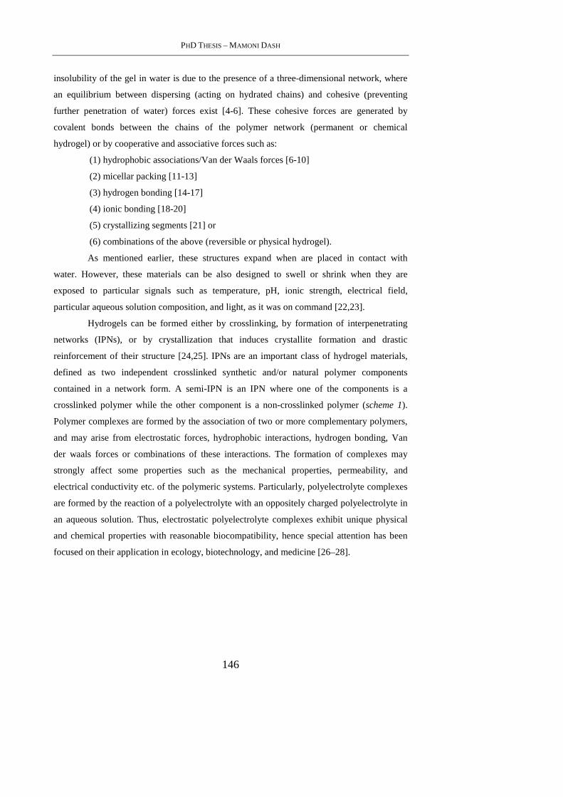
PHD THESIS – MAMONI DASH
146
insolubility of the gel in water is due to the presence of a three-dimensional network, where
an equilibrium between dispersing (acting on hydrated chains) and cohesive (preventing
further penetration of water) forces exist [4-6]. These cohesive forces are generated by
covalent bonds between the chains of the polymer network (permanent or chemical
hydrogel) or by cooperative and associative forces such as:
(1) hydrophobic associations/Van der Waals forces [6-10]
(2) micellar packing [11-13]
(3) hydrogen bonding [14-17]
(4) ionic bonding [18-20]
(5) crystallizing segments [21] or
(6) combinations of the above (reversible or physical hydrogel).
As mentioned earlier, these structures expand when are placed in contact with
water. However, these materials can be also designed to swell or shrink when they are
exposed to particular signals such as temperature, pH, ionic strength, electrical field,
particular aqueous solution composition, and light, as it was on command [22,23].
Hydrogels can be formed either by crosslinking, by formation of interpenetrating
networks (IPNs), or by crystallization that induces crystallite formation and drastic
reinforcement of their structure [24,25]. IPNs are an important class of hydrogel materials,
defined as two independent crosslinked synthetic and/or natural polymer components
contained in a network form. A semi-IPN is an IPN where one of the components is a
crosslinked polymer while the other component is a non-crosslinked polymer (scheme 1).
Polymer complexes are formed by the association of two or more complementary polymers,
and may arise from electrostatic forces, hydrophobic interactions, hydrogen bonding, Van
der waals forces or combinations of these interactions. The formation of complexes may
strongly affect some properties such as the mechanical properties, permeability, and
electrical conductivity etc. of the polymeric systems. Particularly, polyelectrolyte complexes
are formed by the reaction of a polyelectrolyte with an oppositely charged polyelectrolyte in
an aqueous solution. Thus, electrostatic polyelectrolyte complexes exhibit unique physical
and chemical properties with reasonable biocompatibility, hence special attention has been
focused on their application in ecology, biotechnology, and medicine [26–28].
CHAPTER 5 – SYNTHESIS AND CHARACTERIZATION OF SEMI-INTERPENETRATING POLYMER NETWORK
HYDROGEL BASED ON CHITOSAN AND POLY(METHACRYLOYLGLYCYLGLYCINE )
147
Scheme 1: Schematic representation of semi-IPN of Chitosan -poly(MAGlyGly).
Chitosan is a (1,4)-linked 2-amono-2-deoxy-b- D-glucan and can be presented by
N-deacetylation of chitin. Chitosan, as a cationic polyelectrolyte, is able to form
polyelectrolyte complexes by reaction with various natural and synthetic anionic
polyelectrolytes. The electrostatic attraction between the cationic amino groups of chitosan
and the anionic groups of the other polyelectrolyte is the main interaction leading to the
formation of the polyelectrolyte complex. It is stronger than most secondary binding
interactions [29]. These complexes are generally water insoluble and form hydrogels.
Formation of chitosan hydrogels by polyelectrolyte complexation is an interesting alternative
to covalently crosslinked hydrogels. The polyelectrolyte complex undergoes slow erosion,
which gives a more biodegradable material than covalently crosslinked hydrogels [30,31].
Polyelectrolyte complexes of chitosan with other polysaccharides, DNA, proteins and
different synthetic anionic polyelectrolytes have been extensively investigated in literature
due to their wide variety of applications in medicine, pharmacy (especially as drug delivery
systems), technology and other fields [32,33].
In the present work, polymerized MAGlyGly[(poly(MAGlyGly)] has been used as a
polyanionic polymer for complexation with chitosan. Poly(MAGlyGly) has anionically
charged groups that forms polymer complexes with chitosan. The preparation of the
investigated network was performed by free radical polymerization of MAGlyGly in the
presence chitosan acid solution by using ethylene glycol dimethacrylate (EGDMA) as
crosslinking agent and the couple sodium metabisulfite (Na2S2O5) and ammonium persulfate
[(NH4)2S2O8] as radical initiator. The synthetic scheme is presented in figure 1.
The fundamental investigation of the prepared hydrogel involved the Fourier
Transformation Infrared spectroscopy (FTIR) for the structure of the prepared hydrogel and
PHD THESIS – MAMONI DASH
148
at the same time to confirm the presence of both chitosan and poly(MAGlyGly). Physical
and chemical properties of hydrogels depend on their molecular and supramolecular
structure, water content and the type of water. The nature of water in ionic hydrogel
membranes is important in understanding their dynamic and equilibrium swelling behavior
as well as in analyzing solute transport and other diffusive properties of such systems. For
these reasons, the swelling behavior along with the thermal characterizations and state of
water investigation of the hydrogels were performed. Degradability, another important
feature in materials for Regenerative Medicine applications, was performed in the presence
of lysozyme under physiological conditions.
5.3. Materials and Methods
5.3.1 Materials
Chitosan (Mw = 71.3 KDa, degree of deacetylation 93%), ammonium persulfate
[(NH4)2S2O8], sodium metabisulfite (Na2S2O5) and ethylene glycol dimethacrylate(EGDMA)
were purchased from Sigma-Aldrich and they were used without any preliminary
purification. Lysozyme (hen egg-white) was also purchased from Sigma-Aldrich. All other
chemicals were extra pure reagent grade and were used as received.
5.3.2 Methods
5.3.2.1 Preparation of the monomer
Methacryloylglycylglycine (MAGlyGly) was synthesized according to a described
procedure in chapter 4 (§ 4.3.2.1).
5.3.2.2 Silanization of glass
2 mm thick square plates (4x4 cm) were exposed to trimethylclorosilane vapours for
24 hours at room temperature, then rinsed with distilled water and dried.
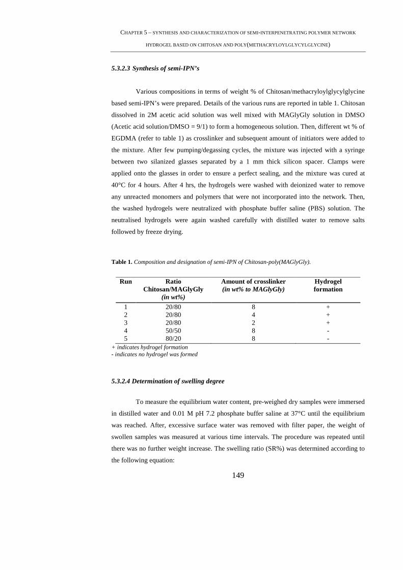
CHAPTER 5 – SYNTHESIS AND CHARACTERIZATION OF SEMI-INTERPENETRATING POLYMER NETWORK
HYDROGEL BASED ON CHITOSAN AND POLY(METHACRYLOYLGLYCYLGLYCINE )
149
5.3.2.3 Synthesis of semi-IPN’s
Various compositions in terms of weight % of Chitosan/methacryloylglycylglycine
based semi-IPN’s were prepared. Details of the various runs are reported in table 1. Chitosan
dissolved in 2M acetic acid solution was well mixed with MAGlyGly solution in DMSO
(Acetic acid solution/DMSO = 9/1) to form a homogeneous solution. Then, different wt % of
EGDMA (refer to table 1) as crosslinker and subsequent amount of initiators were added to
the mixture. After few pumping/degassing cycles, the mixture was injected with a syringe
between two silanized glasses separated by a 1 mm thick silicon spacer. Clamps were
applied onto the glasses in order to ensure a perfect sealing, and the mixture was cured at
40°C for 4 hours. After 4 hrs, the hydrogels were washed with deionized water to remove
any unreacted monomers and polymers that were not incorporated into the network. Then,
the washed hydrogels were neutralized with phosphate buffer saline (PBS) solution. The
neutralised hydrogels were again washed carefully with distilled water to remove salts
followed by freeze drying.
Table 1. Composition and designation of semi-IPN of Chitosan-poly(MAGlyGly).
Run Ratio Chitosan/MAGlyGly
(in wt%)
Amount of crosslinker (in wt% to MAGlyGly)
Hydrogel formation
1 20/80 8 + 2 20/80 4 + 3 20/80 2 + 4 50/50 8 - 5 80/20 8 -
+ indicates hydrogel formation - indicates no hydrogel was formed
5.3.2.4 Determination of swelling degree
To measure the equilibrium water content, pre-weighed dry samples were immersed
in distilled water and 0.01 M pH 7.2 phosphate buffer saline at 37°C until the equilibrium
was reached. After, excessive surface water was removed with filter paper, the weight of
swollen samples was measured at various time intervals. The procedure was repeated until
there was no further weight increase. The swelling ratio (SR%) was determined according to
the following equation:
PHD THESIS – MAMONI DASH
150
SR%=[(Ws-Wd)/Ws]*100
where WS and Wd represent the weight of swollen and dry samples, respectively.
5.3.2.5 Morphological Analysis
The morphology of the prepared hydrogels were investigated by scanning electron
microscopy (SEM), using a JEOL LSM5600LV scanning electron microscope. Lyophilized
hydrogels were used and gold sputtering was done before SEM analysis.
5.3.2.6 Fourier transform infrared (FTIR) spectroscopy measurements
FTIR spectra of chitosan, chitosan-poly(MAGlyGly) hydrogels, poly(MAGlyGly)
in KBr disc form were recorded on Jasco FT–IR 410 spectrophotometer from 400 to 4000
cm-1 with a resolution 4 cm-1 and 32 scans.
5.3.2.7 Differential scanning calorimetry (DSC) measurements
A Mettler DSC-822 (Mettler Toledo, Milan, Italy) differential scanning calorimeter
equipped with a liquid nitrogen cooling accessory was used. DSC was used to analyse the
type of water in the semi-IPN hydrogels. Samples (about 4 mg) were weighed in an
aluminum pan designed for volatile samples and sealed. The samples were cooled to -70°C
at 10°C/min and then heated to 50°C/ at a heating rate of 10°C/min under 80mL/min of
nitrogen flow.
5.3.2.8 Thermogravimetric (TGA) studies
Thermogravimetric analyses were carried out by using Thermogravimetric Analyzer
TGA Q500 (TA Instruments-Waters Division, Milan, Italy). All measurements were
performed with approximately an equal amount (20mg) of samples in aluminum pans. The
experiments were performed from 30°C to 900°C at a scanning rate of 10°C/min under a
60ml/min nitrogen flow.
CHAPTER 5 – SYNTHESIS AND CHARACTERIZATION OF SEMI-INTERPENETRATING POLYMER NETWORK
HYDROGEL BASED ON CHITOSAN AND POLY(METHACRYLOYLGLYCYLGLYCINE )
151
5.3.2.9 In-vitro degradation
The in vitro hydrogels degradation tests were carried out in 4 ml phosphate-buffered
solution (PBS, pH 7.4) at 37 °C containing 1.5 mg/ml lysozyme. The concentration of
lysozyme was chosen to correspond to the concentration in human serum [34,35]. Briefly,
hydrogels of known weight were incubated in the lysozyme solution for the period of study.
The lysozyme solution was refreshed daily to ensure continuous enzyme activity [36]. After
7, 14, 21 and 28 days samples were removed from the medium, rinsed with distilled water
carefully, dried under vacuum and weighed. The extent of in vitro degradation was expressed
as percentage of weight loss of the dried films (n = 3 samples of each week) after lysozyme
treatment. To separate between enzymatic degradation and dissolution, control samples were
stored for 28 days under the same conditions as described above, but without the addition of
lysozyme.
5.4. Results and Discussion
5.4.1 Preparation of Chitosan-poly(MAGlyGly) semi-IPN’s
Figure 1 represents the scheme of the synthesis of IPN composed of chitosan and
poly(MAGlyGly). The preparation of the investigated network was performed by free radical
polymerization of MAGlyGly in the presence chitosan acid solution by using ethylene glycol
dimethacrylate as the crosslinking agent and the couple sodium metabisulfite and ammonium
persulfate as the radical initiator. Briefly, chitosan in acetic acid solution was mixed well in
MAGlyGly solution to form a homogeneous solution. Then the crosslinker EGDMA and the
couple initiators were added to this solution and after a few pumping /degassing cycles, the
resulting mixture were injected between two silanized glasses where it was polymerized at
40°C for 4 hours (figure 2 a). By this technique, homogeneous films with constant thickness
and shape similar to that of the mould (figure 2 b) were obtained. The silanization of the
glasses were done in order to facilitate the hydrogel removal at the end of the
polymerization. The glass surface was silanized by exposure to trimethylchlorosilane
vapours for 24 hours at room temperature and rinsed afterwards with distilled water.
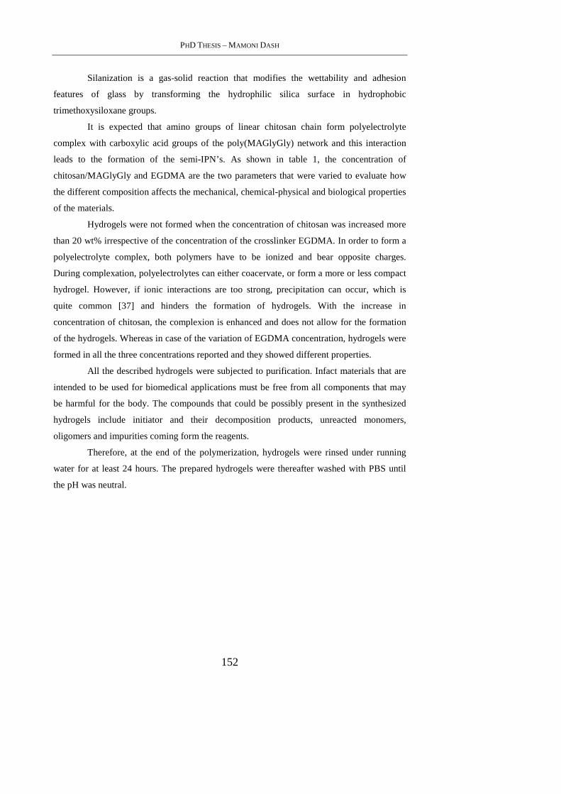
PHD THESIS – MAMONI DASH
152
Silanization is a gas-solid reaction that modifies the wettability and adhesion
features of glass by transforming the hydrophilic silica surface in hydrophobic
trimethoxysiloxane groups.
It is expected that amino groups of linear chitosan chain form polyelectrolyte
complex with carboxylic acid groups of the poly(MAGlyGly) network and this interaction
leads to the formation of the semi-IPN’s. As shown in table 1, the concentration of
chitosan/MAGlyGly and EGDMA are the two parameters that were varied to evaluate how
the different composition affects the mechanical, chemical-physical and biological properties
of the materials.
Hydrogels were not formed when the concentration of chitosan was increased more
than 20 wt% irrespective of the concentration of the crosslinker EGDMA. In order to form a
polyelectrolyte complex, both polymers have to be ionized and bear opposite charges.
During complexation, polyelectrolytes can either coacervate, or form a more or less compact
hydrogel. However, if ionic interactions are too strong, precipitation can occur, which is
quite common [37] and hinders the formation of hydrogels. With the increase in
concentration of chitosan, the complexion is enhanced and does not allow for the formation
of the hydrogels. Whereas in case of the variation of EGDMA concentration, hydrogels were
formed in all the three concentrations reported and they showed different properties.
All the described hydrogels were subjected to purification. Infact materials that are
intended to be used for biomedical applications must be free from all components that may
be harmful for the body. The compounds that could be possibly present in the synthesized
hydrogels include initiator and their decomposition products, unreacted monomers,
oligomers and impurities coming form the reagents.
Therefore, at the end of the polymerization, hydrogels were rinsed under running
water for at least 24 hours. The prepared hydrogels were thereafter washed with PBS until
the pH was neutral.
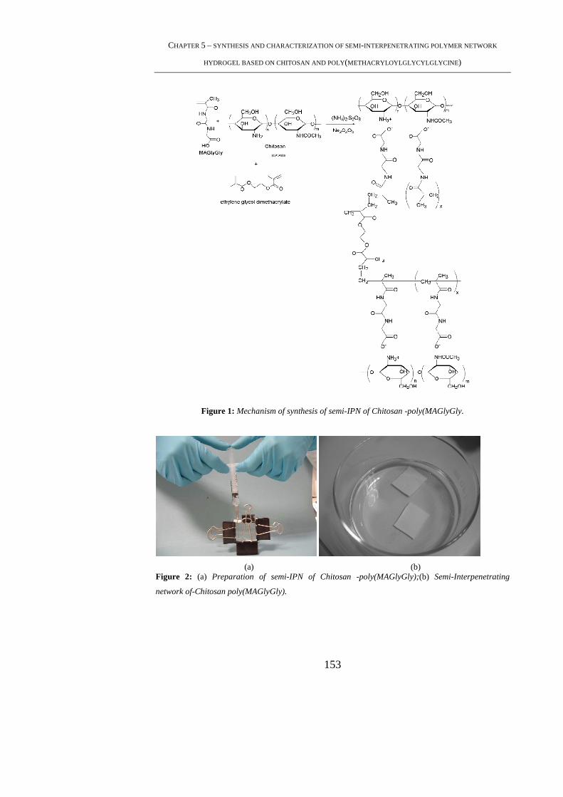
CHAPTER 5 – SYNTHESIS AND CHARACTERIZATION OF SEMI-INTERPENETRATING POLYMER NETWORK
HYDROGEL BASED ON CHITOSAN AND POLY(METHACRYLOYLGLYCYLGLYCINE )
153
Figure 1: Mechanism of synthesis of semi-IPN of Chitosan -poly(MAGlyGly.
(a) (b) Figure 2: (a) Preparation of semi-IPN of Chitosan -poly(MAGlyGly);(b) Semi-Interpenetrating
network of-Chitosan poly(MAGlyGly).
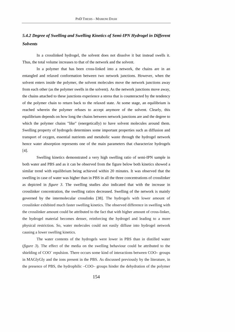
PHD THESIS – MAMONI DASH
154
5.4.2 Degree of Swelling and Swelling Kinetics of Semi-IPN Hydrogel in Different
Solvents
In a crosslinked hydrogel, the solvent does not dissolve it but instead swells it.
Thus, the total volume increases to that of the network and the solvent.
In a polymer that has been cross-linked into a network, the chains are in an
entangled and relaxed conformation between two network junctions. However, when the
solvent enters inside the polymer, the solvent molecules move the network junctions away
from each other (as the polymer swells in the solvent). As the network junctions move away,
the chains attached to these junctions experience a stress that is counteracted by the tendency
of the polymer chain to return back to the relaxed state. At some stage, an equilibrium is
reached wherein the polymer refuses to accept anymore of the solvent. Clearly, this
equilibrium depends on how long the chains between network junctions are and the degree to
which the polymer chains "like" (energetically) to have solvent molecules around them.
Swelling property of hydrogels determines some important properties such as diffusion and
transport of oxygen, essential nutrients and metabolic waste through the hydrogel network
hence water absorption represents one of the main parameters that characterize hydrogels
[4].
Swelling kinetics demonstrated a very high swelling ratio of semi-IPN sample in
both water and PBS and as it can be observed from the figure below both kinetics showed a
similar trend with equilibrium being achieved within 20 minutes. It was observed that the
swelling in case of water was higher than in PBS in all the three concentrations of crosslinker
as depicted in figure 3. The swelling studies also indicated that with the increase in
crosslinker concentration, the swelling ratios decreased. Swelling of the network is mainly
governed by the intermolecular crosslinks [38]. The hydrogels with lower amount of
crosslinker exhibited much faster swelling kinetics. The observed difference in swelling with
the crosslinker amount could be attributed to the fact that with higher amount of cross-linker,
the hydrogel material becomes denser, reinforcing the hydrogel and leading to a more
physical restriction. So, water molecules could not easily diffuse into hydrogel network
causing a lower swelling kinetics.
The water contents of the hydrogels were lower in PBS than in distilled water
(figure 3). The effect of the media on the swelling behaviour could be attributed to the
shielding of COO– repulsion. There occurs some kind of interactions between COO– groups
in MAGlyGly and the ions present in the PBS. As discussed previously by the literature, in
the presence of PBS, the hydrophilic –COO– groups hinder the dehydration of the polymer
CHAPTER 5 – SYNTHESIS AND CHARACTERIZATION OF SEMI-INTERPENETRATING POLYMER NETWORK
HYDROGEL BASED ON CHITOSAN AND POLY(METHACRYLOYLGLYCYLGLYCINE )
155
chains, expanding the collapsed structure [39]. In PBS, the presence of ions produce an ionic
shielding of the –COO– groups, this ionic shielding disrupts the swelling content of the
hydrogels in PBS in comparison to distilled water.
Figure 3: Swelling studies of Chitosan-poly(MAGlyGly) hydrogels in (a) PBS (b) water
5.4.3 Morphological Analysis
The morphological characteristics of the chitosan-poly(MAGlyGly) hydrogels after
exposure to washings with water and PBS and subsequent freeze drying have been examined
by SEM. The microstructure of a scaffold has a prominent influence on cell proliferation,
function, and migration, all of which are key issues in tissue engineering. Microstructures of
the networks surface investigated by scanning electron microscopy are presented in figure 4.
It could be seen that the semi-IPN hydrogels displayed interconnected porous surface. The
porosity increased with the increase in the crosslinker concentration from 2 % to 8 %.
5.4.4 FT-IR Analysis
Fourier transform infrared (FT-IR) spectroscopy was used to confirm the structure
of chitosan -poly(MAGlyGly) semi-IPN hydrogels. Figure 5 shows FT-IR spectra of
chitosan, semi-IPN of chitosan -poly(MAGlyGly) and the MAGlyGly network.
On analyzing the spectrum of chitosan, a characteristic broad band at 3431 cm-1 is
observed due to the overlapping of the stretching vibrations of hydroxyl O-H and amine N-
H2 groups. C-O stretching vibrations of chitosan appear at around 1030 cm-1 . The
characteristic bands of amide I, amide II and amide III appear at around 1651, 1606 and 1383
cm-1respectively. Peaks observed at 2875 and 2919 cm-1 are typical of C-H stretching

PHD THESIS – MAMONI DASH
156
vibrations. The peaks around 894 and 1155 cm-1 correspond to saccharide structure. The
observed peak at 1424 cm-1 is assigned to CH3 symmetrical deformation mode [40].
Figure 4: SEM micrographs of Chitosan-poly(MAGlyGly) hydrogels with(a) 8% EGDMA(b)4%
EGDMA (c )2% EGDMA
On observing the MAGlyGly hydrogel spectrum, carbonyl stretching vibration
(amide I) at 1672 cm-1 and 1540 cm-1due to the N-H bending vibration (amide II) can be
confirmed.
In the chitosan-poly(MAGlyGly) hydrogel , the overlapping of the stretching
vibrations of hydroxyl O-H and amine N-H2 groups appeared at 3432 cm-1 is observed which
is similar to chitosan spectrum. Another similarity to chitosan could be seen in the presence
of the peaks at 2960 and 2919 cm-1 which are typical of C-H stretching vibrations. Moreover
it can be observed peaks at 1656.6 and 1387cm-1 that can be assigned to COO-1 stretching.
Hence, it could be concluded that in the semi-IPN-Chitosan/(MAGlyGly), all the bands of
both chitosan and MAGlyGly hydrogel are observed.
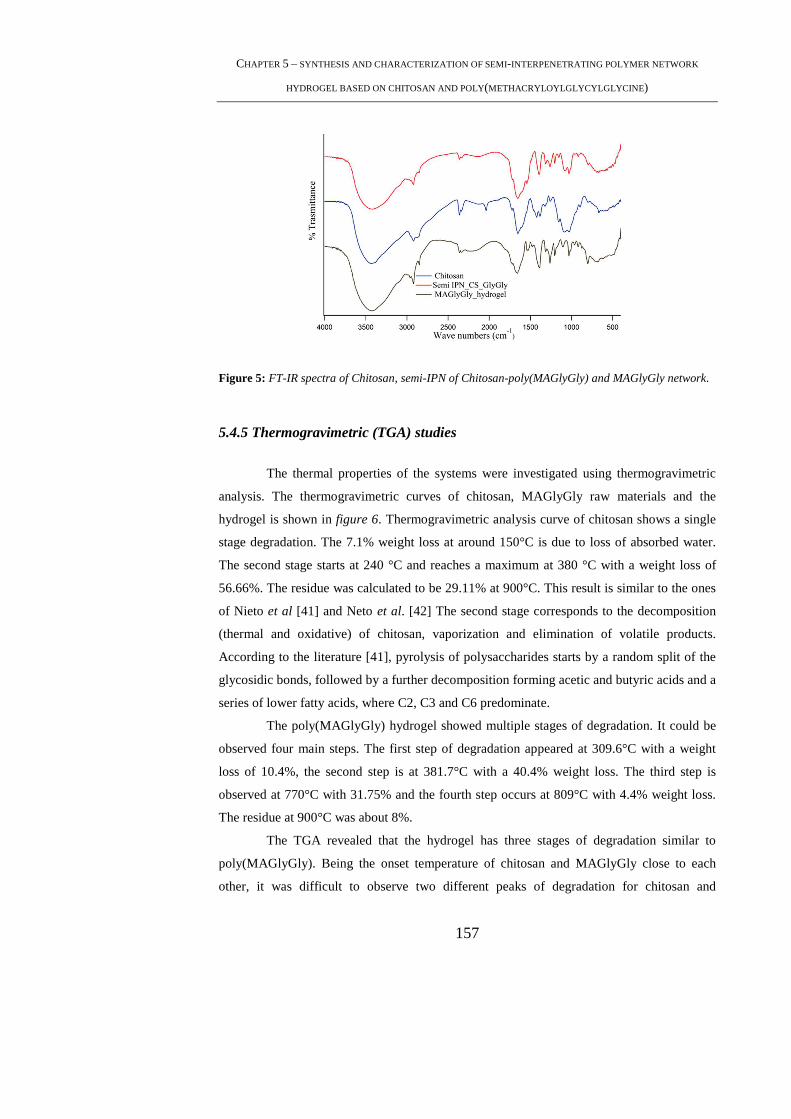
CHAPTER 5 – SYNTHESIS AND CHARACTERIZATION OF SEMI-INTERPENETRATING POLYMER NETWORK
HYDROGEL BASED ON CHITOSAN AND POLY(METHACRYLOYLGLYCYLGLYCINE )
157
Figure 5: FT-IR spectra of Chitosan, semi-IPN of Chitosan-poly(MAGlyGly) and MAGlyGly network.
5.4.5 Thermogravimetric (TGA) studies
The thermal properties of the systems were investigated using thermogravimetric
analysis. The thermogravimetric curves of chitosan, MAGlyGly raw materials and the
hydrogel is shown in figure 6. Thermogravimetric analysis curve of chitosan shows a single
stage degradation. The 7.1% weight loss at around 150°C is due to loss of absorbed water.
The second stage starts at 240 °C and reaches a maximum at 380 °C with a weight loss of
56.66%. The residue was calculated to be 29.11% at 900°C. This result is similar to the ones
of Nieto et al [41] and Neto et al. [42] The second stage corresponds to the decomposition
(thermal and oxidative) of chitosan, vaporization and elimination of volatile products.
According to the literature [41], pyrolysis of polysaccharides starts by a random split of the
glycosidic bonds, followed by a further decomposition forming acetic and butyric acids and a
series of lower fatty acids, where C2, C3 and C6 predominate.
The poly(MAGlyGly) hydrogel showed multiple stages of degradation. It could be
observed four main steps. The first step of degradation appeared at 309.6°C with a weight
loss of 10.4%, the second step is at 381.7°C with a 40.4% weight loss. The third step is
observed at 770°C with 31.75% and the fourth step occurs at 809°C with 4.4% weight loss.
The residue at 900°C was about 8%.
The TGA revealed that the hydrogel has three stages of degradation similar to
poly(MAGlyGly). Being the onset temperature of chitosan and MAGlyGly close to each
other, it was difficult to observe two different peaks of degradation for chitosan and
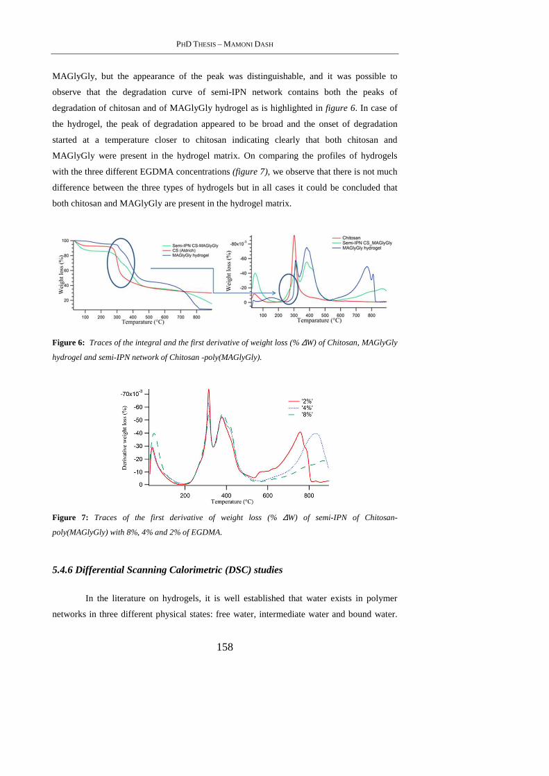
PHD THESIS – MAMONI DASH
158
MAGlyGly, but the appearance of the peak was distinguishable, and it was possible to
observe that the degradation curve of semi-IPN network contains both the peaks of
degradation of chitosan and of MAGlyGly hydrogel as is highlighted in figure 6. In case of
the hydrogel, the peak of degradation appeared to be broad and the onset of degradation
started at a temperature closer to chitosan indicating clearly that both chitosan and
MAGlyGly were present in the hydrogel matrix. On comparing the profiles of hydrogels
with the three different EGDMA concentrations (figure 7), we observe that there is not much
difference between the three types of hydrogels but in all cases it could be concluded that
both chitosan and MAGlyGly are present in the hydrogel matrix.
Figure 6: Traces of the integral and the first derivative of weight loss (% ∆W) of Chitosan, MAGlyGly
hydrogel and semi-IPN network of Chitosan -poly(MAGlyGly).
Figure 7: Traces of the first derivative of weight loss (% ∆W) of semi-IPN of Chitosan-
poly(MAGlyGly) with 8%, 4% and 2% of EGDMA.
5.4.6 Differential Scanning Calorimetric (DSC) studies
In the literature on hydrogels, it is well established that water exists in polymer
networks in three different physical states: free water, intermediate water and bound water.
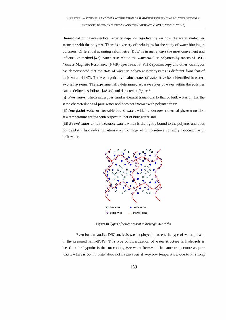
CHAPTER 5 – SYNTHESIS AND CHARACTERIZATION OF SEMI-INTERPENETRATING POLYMER NETWORK
HYDROGEL BASED ON CHITOSAN AND POLY(METHACRYLOYLGLYCYLGLYCINE )
159
Biomedical or pharmaceutical activity depends significantly on how the water molecules
associate with the polymer. There is a variety of techniques for the study of water binding in
polymers. Differential scanning calorimetry (DSC) is in many ways the most convenient and
informative method [43]. Much research on the water-swollen polymers by means of DSC,
Nuclear Magnetic Resonance (NMR) spectrometry, FTIR spectroscopy and other techniques
has demonstrated that the state of water in polymer/water systems is different from that of
bulk water [44-47]. Three energetically distinct states of water have been identified in water-
swollen systems. The experimentally determined separate states of water within the polymer
can be defined as follows [48-49] and depicted in figure 8:
(i) Free water, which undergoes similar thermal transitions to that of bulk water, it has the
same characteristics of pure water and does not interact with polymer chain.
(ii) Interfacial water or freezable bound water, which undergoes a thermal phase transition
at a temperature shifted with respect to that of bulk water and
(iii) Bound water or non-freezable water, which is the tightly bound to the polymer and does
not exhibit a first order transition over the range of temperatures normally associated with
bulk water.
Figure 8: Types of water present in hydrogel networks.
Even for our studies DSC analysis was employed to assess the type of water present
in the prepared semi-IPN’s. This type of investigation of water structure in hydrogels is
based on the hypothesis that on cooling free water freezes at the same temperature as pure
water, whereas bound water does not freeze even at very low temperature, due to its strong

PHD THESIS – MAMONI DASH
160
interaction with the polymer matrix [4]. According to this hypothesis the endotherm
measured when warming the frozen gel represents the melting of free water and that value
will yield the amount of free water in the hydrogel being tested.
The heat of crystallization of the freezing water (intermediate and free water) was
determined from the area under the exothermic curve and was calibrated using pure distilled
water as a standard (figure 9). In particular the amount of freezing water (Wf) was
determined by comparing the ∆H of the crystallization peak of the hydrated sample with that
of the pure water:
w
w
f
QW
°∆=
H
where Qw is the crystallization enthalpy measured in Joule (J) and ∆H°w is the solid-liquid
transition enthalpy of hydration water in the hydrogel. By assuming that the crystallization
enthalpy of hydration water is the same in pure water and in the hydrogel, the experimentally
measured value of ∆H°w turned out to be 495.31 J·g-1.
Figure 9 DSC trace of pure water.
The content of not-freezing water (Wnf) in the hydrogel was then evaluated as the
total hydration water (Wt) minus the amount of freezing water (Wf):
ftnf WWW −=
From the DSC analysis of the semi-IPN hydrogels, it was observed that most part of
water is present as freezing water (figure 10). This result could be interpreted by considering
the fact that with the formation of the polyelectrolyte complex between chitosan and
poly(MAGlyGly) there are fewer hydrophilic groups available. When the amount of
crosslinker is reduced to 4% and 2% , the amount of bound water in the system increases
(figure 10). This could be explained on the basis that with lesser crosslinker amount, the pore
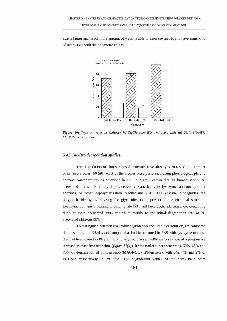
CHAPTER 5 – SYNTHESIS AND CHARACTERIZATION OF SEMI-INTERPENETRATING POLYMER NETWORK
HYDROGEL BASED ON CHITOSAN AND POLY(METHACRYLOYLGLYCYLGLYCINE )
161
size is larger and hence more amount of water is able to enter the matrix and have some kind
of interaction with the polymeric chains.
Figure 10: Type of water in Chitosan-MAGlyGly semi-IPN hydrogels with (a) 2%(b)4%(c)8% EGDMA concentration
5.4.7 In-vitro degradation studies
The degradation of chitosan based materials have already been tested in a number
of in vitro studies [50-59]. Most of the studies were performed using physiological pH and
enzyme concentrations as described herein. It is well known that, in human serum, N-
acetylated chitosan is mainly depolymerized enzymatically by lysozyme, and not by other
enzymes or other depolymerization mechanisms [51]. The enzyme biodegrades the
polysaccharide by hydrolyzing the glycosidic bonds present in the chemical structure.
Lysozyme contains a hexameric binding site [53], and hexasaccharide sequences containing
three or more acetylated units contribute mainly to the initial degradation rate of N-
acetylated chitosan [57].
To distinguish between enzymatic degradation and simple dissolution, we compared
the mass loss after 28 days of samples that had been stored in PBS with lysozyme to those
that had been stored in PBS without lysozyme. The semi-IPN network showed a progressive
increase in mass loss over time (figure 11(a)). It was noticed that there was a 60%, 68% and
76% of degradation of chitosan-poly(MAGlyGly) IPN-network with 8%, 4% and 2% of
EGDMA respectively in 28 days. The degradation values of the semi-IPN’s were

PHD THESIS – MAMONI DASH
162
significantly higher than the controls used which indicated enzymatic degradation of the
semi-IPN’s. However a minimum of loss in weight is detected also in the control samples.
The increase in the degradation rate with the decrease in crosslinker amount was hard to
interpret. With the decrease in crosslinker the pore size as well as the swelling increased, this
caused more dissolution of the samples and their removal during subsequent refreshments. A
comparison of the degradation values of the three kind of the semi-IPN hydrogels with their
respective controls are shown in figure 11(b).
For MAGlyGly hydrogels, a clear distinction between degradation and dissolution
could not be made under the adopted investigation conditions since the MAGlyGly
hydrogels had a highly porous strucuture where dissolution could not be controlled.
a) b)
Figure 11: (a)Progressive mass loss of semi-IPN Chitosan- poly(MAGlyGly) after storage in PBS at
37°C with 1.5 µg/mL of lysozyme. (b) Comparison of the mass loss % of semi-IPN of Chitosan-
poly(MAGlyGly) in lysozyme and their respective controls in PBS.
5.5. Conclusion
The semi-IPN of chitosan-poly(MAGlyGly) were prepared. To gain insights on the
influence of factors that could affect the formation of the hydrogels, the ratio of the
concentration of the polymer/monomer were varied. The influence of the crosslinker on the
type and properties of the hydrogels were also studied. Some important features of the
hydrogels in terms of various applications like swelling, type of water etc. were studied in
detail. It was observed that properties like swelling, morphology and type of water were
inversely related to the amount of crosslinker. With the decrease in the amount of
crosslinker, the semi-IPN’s had a larger pore size. The semi-IPN’s showed an increase in

CHAPTER 5 – SYNTHESIS AND CHARACTERIZATION OF SEMI-INTERPENETRATING POLYMER NETWORK
HYDROGEL BASED ON CHITOSAN AND POLY(METHACRYLOYLGLYCYLGLYCINE )
163
swelling ratio and the percentage of bound water increased with the decrease in crosslinker
amount. Physico-chemical characterizations like FT-IR and TGA led us to confirm the
presence of both the constituents in the matrix of the hydrogel. Lysozyme degraded the
hydrogel matrix to a maximum of 76% for the hydrogel with 2% EGDMA concentration.
However, even if some dissolution was observed along with degradation under physiological
conditions still the difference between the two was noticeable. The prepared semi-IPN
constructs appear to be a promising material for regenerative medicine applications.
5.6. References
[1] Chen, J., Jo, S., Park, K.; Degradable hydrogels. In: Domb AJ, Kost J, Wiseman DM,
editors. Handbook of biodegradable polymers. Amsterdam: Overseas Publishers Association,
1997 , 203
[2] Odian, G., Principles of polymerisation. New York: John Wiley and Sons, Inc.; 1991 ,
149
[3] Ku° dela, V.,. Hydrogels. In: Kroschwitz JI, editor. Polymers: Biomaterials and medical
applications. New York: John Wiley and Sons, Inc;1989 , 228
[4] Hoffman, A.S.; Adv Drug Deliv Rev, 2002 ,3
[5] Peppas, N.A., Bures, P., Leobandung, W., Ichikawa, H. ; Eur J Pharm Biopharm ,
2000,27.
[6] Guenet, J.M.; Thermoreversible gelation of polymers and biopolymers. London:
Academic Press, 1992
[7] Cho, J., Heuzey, M.C., Begin, A., Carreau, P.J.; Biomacromolecules, 2005 ,3267.
[8] Rajagopal, K., Ozbas, B., Pochan, D.J., Schneider, J.P.; Eur Biophys J , 2006,162.
[9] Kohler, K., Forster, G., Hauser, A., Dobner, B., Heiser, U.F., Ziethe, F., Richter, W.,
Steiniger ,F., Drechsler, M., Stettin ,H., Blume, A.;J Am Chem Soc , 2004,16804.
PHD THESIS – MAMONI DASH
164
[10] Nowak, A.P., Breedveld, V., Pakstis, L., Ozbas, B., Pine DJ, Pochan,D. ,Deming,
T.J.;Nature 2002, 388
[11] Determan, M.D., Guo, L., Thiyagarajan ,P., Mallapragada, S.K.;Langmuir, 2006,1469.
[12] Grant, C.D., DeRitter ,M.R., Steege, K.E., Fadeeva, T.A., Castner, E.W. Jr.,. Langmuir ,
2005,1745.
[13] Wright, E.R., Conticello, V.P., Apkarian ,R.P., Microsc Microanal, 2003 ,17123.
[14] Kimura, M., Fukumoto, K., Watanabe, J., Ishihara, K., J Biomater Sci Polym Ed
2004,631.
[15] Juszczak, L.J.,J Biol Chem , 2004,7395.
[16] Percec, V., Bera, T.K., Bufera, R.J., Biomacromolecules, 2002,272
[17] Kiyonaka, S., Shinkai, S., Hamachi, I.,Chemistry , 2003,976.
[18] Van Tomme, S.R., Van Steenbergen, M.J., De Smedt, S.C., Van Nostrum, C.F.,
Hennink, W.E., Biomaterials, 2005 ,2129
[19] Uludag, H., De Vos, P., Tresco, P.A., Adv Drug Deliv Rev, 2000 ,29.
[20] Baruch, L., Machluf, M., Biopolymers, 2006,570.
[21] Stenekes, R.J., Talsma, H., Hennink, W.E.; Biomaterials, 2001, 1891.
[22] Jeong, B., Kim, S.W., Bae, Y.H., Adv Drug Deliv Rev, 2002,37.
[23] Qiu, Y., Park, K., Adv Drug Deliv Rev ,2001,321.
[24] Aharoni, S. M.; Plenum Press: New York, 1992.
CHAPTER 5 – SYNTHESIS AND CHARACTERIZATION OF SEMI-INTERPENETRATING POLYMER NETWORK
HYDROGEL BASED ON CHITOSAN AND POLY(METHACRYLOYLGLYCYLGLYCINE )
165
[25] Klempner, O., Utracki, L. A. Sperling, L. H.; Adv Chem Ser ,1991, 239.
[26] Michaels, A. S. ;Ind Eng Chem, 1965, , 32.
[27] Blumstein, A., Kakivaya, S. R., Salamone, J. C.; J Polym Sci, 1974, 651.
[28] Scranton, A. B., Klier, J., Aronson, C. L.; ACS Symposium Series, 1992, 171.
[29] Lee, J.W., Kim, S.Y., Kim, S.S., Lee, Y.M. , Lee, K.H., Kim, S.J.; J. Appl. Polym. Sci.
1999,113.
[30] Torre, P.M., Enobakhare, Y., Torrado, G. , Torrado, S.; Biomaterials, 2003, 1499.
[31] Noble, L., Gray, A.I., Sadiq, L. ,Uchegbu, I.F.; Int, J. Pharm.,1999, 173.
[32] Berger, J., Reist, M., Mayer, J. M., Felt, O., Gurny, R.; Eur J Pharm Biopharm, 2004,
35.
[33] Berger, J., Reist, M., Mayer, J. M., Felt, O., Peppas, N. A., , Gurny, R.; Eur J Pharm
Biopharm, 2004, 19.
[34] Brouwer, J., Van Leeuwen-Herberts, T., Otting-van de Ruit, M.; Clin Chim Acta ,1984,
21.
[35] Porstmann, B., Jung, K., Schmechta, H., Evers, U., Pergande, M., Porstmann, T.,
Kramm, H.J., Krause, H.; Clin Biochem ,1989,349.
[36] Masuda, T., Ueno, Y., Kitabatake, N.; J Agric Food Chem ,2001,4937.
[37] Yao, K.D., Tu, H., Cheng, F., Zhang, J.W., Liu, J., Angew Makromol. Chem. 1997, 63.
[38] Reddy, T. T., Lavenant, L., Lefebvre, J., Renard ,D.; Biomacromolecules ,2006, 323
[39] Yue-qin, Yu., Yang, X., Hansheng, Ning., Shu-sheng, Z.; Colloid Polym Sci
,2008,1165.
PHD THESIS – MAMONI DASH
166
[40] Al-Kahtani, A.A., Sherigara, B.S.; J. Mater. Sci.: Matr. Med., 2009, 1437.
[41] Nieto, J. M., Peniche-Covas, C., Padron, G.;Thermochimica Acta, 1991, 63.
[42] Neto, C.G.T., Giacomettib, J.A., Jobb, A.E., Ferreirab, F.C., Fonsecaa, J.L.C., Pereiraa,
M.R.; Carbohydrate Polymers, 2005, 97
[43] Corkhill, P. H., Jolly, A. M., Ng, Ch. O., Tighe, B. J.; Polymer, 1987, 1758.
[44] Hatakeyama, H., Hatakeyama, T.; Thermochimica Acta, 1998, 3.
[45] McBrierty, V. J., Martin, S. J., Karasz, F. E.; J Mol Liq, 1999,179.
[46] Ping, Z. H., Nguyen, Q. T., Chen, S. M., Zhou, J. Q., Ding, Y. D.; Polymer, 2001,8461.
[47] Tamai, Y., Tanaka, H., Nakanishi, Y.; Macromolecules, 1996,6750.
[48]Higuchi, A., Komiyama, J., Iijima, T.; Polymer Bulletin, 1984, 203.
[49] Hodge, R. M., Edward, G. H., Simon, G. P.; Polymer, 1996, 1371.
[50] Tomihata ,K., Ikada, Y.; Biomaterials 1997,567.
[51] Varum, K.M., Myhr, M.M., Hjerde, R.J.N., Smidsrod, O.; Carbohydr Res, 1997,99.
[52] Lee ,K.Y., Ha, W.S., Park, W.H.; Biomaterials, 1995,1211–6.
[53] Pangburn, S.H., Trescony, P.V., Heller, J. ; Biomaterials, 1982,105.
[54] Hirano, S., Tsuchida, H., Nagao, N.; Biomaterials, 1989,574.
[55] Sashiwa, H., Saimoto, H., Shigemasa, Y.; Int J Biol Macromol ,1990,295.
[56] Aiba, S.; Int J Biol Macromol, 1992,225–8.
CHAPTER 5 – SYNTHESIS AND CHARACTERIZATION OF SEMI-INTERPENETRATING POLYMER NETWORK
HYDROGEL BASED ON CHITOSAN AND POLY(METHACRYLOYLGLYCYLGLYCINE )
167
[57] Shigemasa, Y., Saito, K., Sashiwa, H., Saimoto, H.; Int J Biol Macromol ,1994,43.
[58] Nordtveit, R.J., Varum, K.M., Smidsrod, O.; Carbohydr Polym ,1994,253.
[59] Nordtveit, R.J., Varum, K.M., Smidsrod, O.; Carbohydr Polym, 1996,163.

PHD THESIS – MAMONI DASH
168
169
OVERALL CONCLUSIVE REMARKS AND FUTURE
PERSPECTIVES
Materials for Tissue Engineering (TE) have significantly progressed over the years,
from being initially viewed as biologically inert structural supports to platforms capable of
providing signals to cells and tissues to orchestrating tissue regeneration. Current trends
suggest that biomaterial development will continue to create more life-like multi-functional
materials that are able to simultaneously provide complex biological signals (chemical,
structural and mechanical), replace mechanical function and respond to environmental
stimuli. A continuing challenge for this approach will be to find ways of exploiting these
sophisticated tools without unduly complicating large-scale production for clinical research.
We have summarized a wide range of materials that are frequently used to date, or will
potentially be useful in TE in the future. Concluding remarks on individual section of the
thesis have been listed below.
(1) Chitosan- A Versatile Material for Regenerative Medicine Applications
A review on the current status of chitosan usage in Regenerative Medicine
applications has been done. Chitosan appears to be one of the most promising biomaterials in
TE because it offers a distinct set of advantageous physico-chemical and biological
properties such as non-allergenicity, biocompatibility, biodegradability and cationic surface
charges in acidic medium allowing for applications in a variety of conventional and
pharmaceutical areas. In this review, various techniques used for preparing chitosan micro/
nanoparticles and hydrogels have been listed.
An updated study of the various applications of chitosan in TE, Drug Delivery, Gene
Therapy and the most emerging Boimaging areas has been done. In conclusion, the survey
demonstrated that chitosan as a biopolymer holding valuable and immense promise.
(2) Statistical Approach of Chitin Deacetylation
Chitosan was prepared from chitin by a heterogeneous deacetylation process using
alkaline medium. Two reaction parameters, namely reaction time and temperature were
varied in order to prepare various chitosan grades characterized by different acetylation
degrees (DA). Based on this data, a statistical model was developed that can be used to
define reaction conditions to obtain a specific value of DA.
PHD THESIS – MAMONI DASH
170
(3) Chitosan-Based Beads for Controlled Release of Proteins
Extensive research is being carried out to exploit chitosan as a drug carrier to attain
the desirable drug release profiles. The preparation of microspheres or beads are based on a
therapy that offer numerous advantages over the conventional dosage forms. These include
improved efficacy, reduced toxicity and improved patient compliance. Our approach was
similar, in preparing beads of chitosan and loaded with proteins (HSA and PT). Chitosan
beads of 700-800 µm were obtained with a satisfactory degree of encapsulation of the two
types of proteins Encapsulation efficiency was dependent on the time and temperature to
which the beads were allowed to crosslink. It was observed that when beads were allowed to
remain in the crosslinking medium for 24 hrs at room temperature, there was recorded
maximum encapsulation of about 64% . The release of the two proteins depended on the
molecular weight of the respective proteins with trypsin being released faster than HSA. The
degradation profile of the beads has been presented in a medium containing lysozyme.
Although a lot of work is still included in our future perspective, we were able to optimise
the basic conditions of preparation of the beads, encapsulation and release of the proteins.
(4) Hybrid Nanoparticles Based on Chitosan and Poly(Methacryloylglycylglycine)
In this chapter, our approach was focused on the preparation and characterization of
nanoparticles based on chitosan. The nanoparticulate systems have great potentials, being
able to convert poorly soluble, poorly absorbed and labile bioactive agents into promising
deliverable drugs. The core of this system can enclose a variety of drugs, enzymes, genes and
is characterized by a long circulation time due to the hydrophilic shell which prevents
recognition by the Reticular-Endothelial System (RES). In our work, we tried to achieve the
above said properties by combining the benefits of chitosan with that of an anionic
poly(acrylamide) of carboxyl end capped of the glycine dimer,[poly(MAGlyGly)]. In this
regard, we synthesized the monomer MAGlyGly and with their respective group interactions
formed nanoparticles by using chitosan and poly(MAGlyGly) polymerized in-situ. Using
various ratios of chitosan and MAGlyGly, nanoparticles of 100-120 nm were successfully
prepared with good morphology and shape. Their interaction was established using FT-IR
and XPS wherein the presence of all constituents in the nanoparticle matrix was confirmed.
Our next step is to load drugs for a sustained release from the prepared nanoparticles.

CONCLUSIONS
171
(5) Synthesis and Characterization of Semi Interpenetrating Polymer Network
Hydrogel Composed of Chitosan and Poly(methacryloylglycyl glycine)
Hydrogels have become increasingly studied as matrices for tissue engineering.
These devices are usually passive exchange systems, but more recently experimental
systems may contain entrapped or encapsulated cells from other human or animal sources.
We synthesized hydrogels based on the concept of semi-IPN’s wherein the monomers and/or
polymers plus crosslinkers are mixed, followed by simultaneous polymerizations via non-
interfering reactions. EGDMA was used as a crosslinker with Na2S2O5 and (NH4)2S2O8 as the
free radical initiator. Our prepared chitosan/poly(MAGlyGly) semi-IPN showed promising
properties. The amount of the co-polymers and the crosslinking agent were varied to obtain
semi-IPN’s and observe their various properties. Evaluation of the preparation conditions
were stressed on, it was found that above 20 %wt of chitosan semi-IPN’s were not formed
irrespective of the amount of crosslinker used. It was also observed that there was
dependence of certain properties like swelling, morphology and type of water with the
amount of crosslinker. The prepared semi-IPN’s showed a very high swelling percentage in
both PBS and water with most of the water present as free water. The interconnected porous
hydrogels proved to be thermally stable under physiological conditions. Degradation of the
prepared semi-IPN’s were studied in the presence of lysozyme under physiological
conditions. The biological investigations of the semi-IPN’s will constitute the objective of
further investigations.
The scientific and technology development are a never ended journey. Each closed
research project opens a new range of questions and technological capabilities that can be
explained and exploited in multiple directions. The worked developed in the scope of this
thesis is not an exception. Herein, we intended to highlight some points that might be
interesting and fruitful to exploit in forthcoming investigations.
PHD THESIS – MAMONI DASH
172
173
ACKNOWLEDGEMENT
As I write the last part of my thesis, I have so many good memories to reminisce.
This may not be the best occasion to disclose my feelings but this thesis being a very
important accomplishment in my life, I would like to take this opportunity to thank so many
around me, whom otherwise would be difficult to let them know how special they are for me.
To begin with, my family, who are far from me only in terms of distance, they
dwell within me!. The three of them, Mummy, Babu & Moon chua have been an enormous
source of strength invariably. They have always realised my dreams through their own eyes,
standing strong as a pillar at times of need. It is, indeed, hard to put down on paper, what
they mean to me.....
I would always remain obliged to Prof. Emo Chiellini for providing me this life
time opportunity to do a Ph.D under his supervision. I learnt so much in his lab and had a
great ambience to understand science along with having a possibility to feel another culture.
Prof. Chiellini’s level of energy is incredible as well as contagious!. I saw a supervisor who
begins working before his students and finishes after them. Indeed, a very respectable and
admirable personality!. A special word of thanks to my tutor Dr.Federica Chiellini, all
through these years she was a constant support with ever encouraging words and has made
substantial contribution in shaping the thesis. Besides, her role as tutor, I always felt a special
relation with her. With a great smile that she has, she was always prompt in extending all
kinds of help that she could. Whenever in need, I felt compassion and warmth in her
approaches. Thank you! for everything, including “castagnaccio” from little Eugenia. Back
in India, I would like to acknowledge, Prof. Banamali Pradhan, who has always persuaded
me to achieve the highest standards in research and academics.
Beth - a fantastic teacher, she shaped and gave a attitude to my scientific thinking.
Time spent with her are really brain stimulating. Thank you, Beth for being kind enough to
spend those long hours, also during weekends, talking on diverse things from research to
culture and for making an impressive contribution to this thesis. Here in Pisa, I spent a
budding phase of my life both personally as well as professionally. I made friends that I am
PHD THESIS – MAMONI DASH
174
proud of and will cherish their friendship all my life. My days in BIOLAB usually begun
with a warm welcome by Dr. Ferri, I will really miss his gestures that made me feel at home.
Anna, don’t know what to tell about her, a person with so much positivity for life. Optimism
and cheerfulness are synonymous to her and now these have been well inherited by our little
Letizia. At times of stress, I always found her beside, alleviating me Thanks! Anna, for your
guidance and affection. Marcella- I will do an injustice if I call her just a friend. She was a
sister that this place gifted me. I have spent some really good time with her in the labs of
BIOLAB, that served as spots to exchange almost each and every bits and pieces of our daily
lives. Thank you for all your love and also for giving me a chance to see Agnese. It is also
inevitable to acknowledge a good friend Stefania for professional assistance in doing the
XPS analysis as well as for being kind enough to give me a lift back from BIOLAB,
occasionally.
BIOLAB, was a place with fun and liveliness, a place that gave me a bag full of
good friends. Veska, Cristina, Matteo, Andrea, Alberto- a great company to be with while
working in labs, a wonderful musician- I wish him good luck to fulfil his dream of becoming
a very famous musician someday, Cesare- I will miss cleaning the kitchen with him and also
the BMP experiments, Silvia, even if she was far, I always knew I had a well-wisher, Dario,
Nicola, Dino, Marco, Carlos, Muhammad, Shiva, Sudhakar, Ariana & all the new faces of
this year.
A deep sense of acknowledgement also goes to both the Maria’s and Michela. The
help extended by Maria 1(as we address her to distinguish) is unforgettable for me. As a
young girl with high aims, I admired so much her encouraging mails. I will forever remain
grateful for all her assistance. The long hours of standing in Questura with Maria 2 is still so
fresh in my memory. I cannot express how sorry I am, for bothering her and how thankful I
am, for all those cooperation that I have received. Michela, with her courteous behaviour was
ever ready to lend an ear to our problems.
To end, my stay in Pisa is indebted to my best friend, Shelly . To put it very
candidly, I cannot thank Shelly in words for the contribution that she has made in my life
during these years. I wish the best in life for her in all her endeavours.
175
Professional assistance provided by Mr.Peiro Narducci in performing the SEM is
also duely acknowledged. The present thesis was performed within the framework of “NOE-
Expertissues” CT-2004-500328 and PRIN-2006.

PHD THESIS – MAMONI DASH
176
APPENDIX
PUBLICATIONS & LIST OF CONTRIBUTIONS IN CONFERENCES AND
WORKSHOPS
Conferences:
M.Dash, M.Ferri, S.Cometa and F.Chiellini: Evaluation of hybrid nanoparticles of
chitosan/methacryloylglycyl glycine for biomedical applications, 2nd International Congress
on Biohydrogels, 10-15th November, Viareggio (Italy), 2009– oral presentation.
M.Dash, M.Ferri, S.Cometa and F. Chiellini: Preparation and characterization of
chitosan/methacryloylglycyl glycine based nanoparticles for biomedical applications, VII
CONVEGNO NAZIONALE INSTM SULLA SCIENZA E TECNOLOGIA DEI
MATERIALI TIRRENIA(PI) 9-12 GUIGNO 2009-poster presentation
M.Dash, M.Ferri, F.Chiellini ; Biocompatible polymeric materials for regenerative medicine
applications; 2° Forum Nazionale Giovani Ricercatori su Materiali Polimerici e Biomateriali,
Genova (Italy), 4-5th July, 2008– poster presentation.
M.Dash, F.Chiellini, A.M. Piras and E. Chiellini: Micro and Nano Biomaterials for
regenerative medicine. International Congress on Biohydrogels, 14–17th November,
Viareggio (Italy), 2007– oral presentation.
M.Dash, F. Chiellini, E. Chiellini,; Bioactive polymeric material for regenerative medicine
applications; 14th CIRMIB Biomaterials School on Nanomedicine: Imaging, Drug Release,
Regenerative Medicine, 9–13th July, Ischia (Italy), 2007– oral presentation.
Book Chapter:
A.M.Piras, C.Errico, M.Dash, M.Ferri, E.Chiellini, F.Chiellini. Polymeric Nanoparticles for
Targeted Release of Conventional and Macromolecular Drugs(preparation and
characterization aspects). In Remaesh S. Chaughule and Raju V. Ramanujan (Ed)

177
NANOPARTICLES: From Synthesis to Application. American Scientific Publishers,25650
Lewis Way, Stevenson Ranch, California 91381-1439, USA.(2009). In press
M.Dash, A.M.Piras, F.Chiellini, “Chitosan based beads for controlled release of proteins” in
Biohydrogels, Rolando Barbucci (Ed.), Springer-Verlag, Milan – Italy (2009), pp 111 –120.