Binary Output without Power Supply Series 9176 · 2018-04-02 · x x x x x x Ex i interface x x x...
14
Binary Output without Power Supply Series 9176 www.stahl.de Isolators A3/1 2015-04-02·AK00·III·en A3 A3 A3 A3 A3 A3 A3 A3 A3 A3 A3 A3 A3 A3 Series 9176 A3 10495E00 WebCode 9176A > For intrinsically safe operation of Ex i solenoid valves, indicators and horns > Power supply by control circuit, loop powered > Intrinsically safe output [Ex ia] IIC / [Ex ib] IIC > Galvanic isolation between inputs and outputs > For use up to SIL 3 (IEC 61508) Binary outputs are used for intrinsically safe operation of Ex i solenoid valves, indicator lamps or horns. Power supply of the devices is carried out via a control circuit, thus, no separate auxiliary power supply is required. Binary output is available in single or double channel versions. Outputs of the double channel version are galvanically separated. IECEx / ATEX NEC 505 NEC 506 NEC 500 Class I Class I Class II Class III Zone 0 1 2 20 21 22 Zone 0 1 2 20 21 22 Division 1 2 1 2 1 2 Ex i interface x x x x x x Ex i interface x x x Ex i interface x x x x x x Installation in x x Installation in x x Installation in x x x
Transcript of Binary Output without Power Supply Series 9176 · 2018-04-02 · x x x x x x Ex i interface x x x...

Binary Output without Power SupplySeries 9176
ww
w.s
tah
l.d
e
Isolators A3/12015-04-02·AK00·III·en
A3
A3
A3
A3
A3
A3
A3
A3
A3
A3
A3
A3
A3
A3
Series 9176 A3
10495E00
WebCode 9176A
> For intrinsically safe operation of Ex i solenoid valves, indicators and horns
> Power supply by control circuit, loop powered
> Intrinsically safe output [Ex ia] IIC / [Ex ib] IIC
> Galvanic isolation between inputs and outputs
> For use up to SIL 3 (IEC 61508)
Binary outputs are used for intrinsically safe operation of Ex i solenoid valves, indicator lamps or horns.Power supply of the devices is carried out via a control circuit, thus, no separate auxiliary power supply is required.Binary output is available in single or double channel versions.Outputs of the double channel version are galvanically separated.
IECEx / ATEX NEC 505 NEC 506 NEC 500Class I Class I Class II Class III
Zone 0 1 2 20 21 22 Zone 0 1 2 20 21 22 Division 1 2 1 2 1 2Ex i interface
x x x x x x Ex iinterface
x x x Ex iinterface
x x x x x x
Installation in x x Installation in x x Installation in x x x

Binary Output without Power SupplySeries 9176
Isolators 2015-04-02·AK00·III·enA3/2
Selection TableVersion Channels No-load
voltage UoutMax. output current Iout max
Internal resistance Ri
Order number Tech. data see page
Binary output without power supply Series 9176
1 10 V 60 mA 150 Ω 9176/10-12-00s 317.5 V 45 mA 130 Ω 9176/10-14-00s 525 V 29 mA 320 Ω 9176/10-15-00s 7
35 mA 250 Ω 9176/10-16-00s 943 mA 460 Ω 9176/10-17-00s 11
2 10 V 60 mA / 120 mA *) 150 Ω / 75 Ω *) 9176/20-12-00s 317.5 V 45 mA / 90 mA *) 130 Ω / 65 Ω *) 9176/20-14-00s 525 V 29 mA / 58 mA *) 320 Ω / 160 Ω *) 9176/20-15-00s 7
35 mA / 70 mA *) 250 Ω / 125 Ω *) 9176/20-16-00s 943 mA / 86 mA *) 460 Ω / 230 Ω *) 9176/20-17-00s 11
Note The order numbers listed in the table are for devices equipped with screw-type terminals.For devices equipped with spring-type terminals, replace the ending "s" for screw-type terminals with "k" for spring-type terminals.*) Parallel connection of the outputs possible. Doubling of the output current.
Explosion ProtectionGlobal (IECEx)
Gas and dust IECEx BVS 13.0012 XEx nA [ia Ga] IIC T4 Gc[Ex ia Da] IIIC
Europe (ATEX)Gas and dust BVS 04 ATEX E 075 X
E II 3 (1) G Ex nA [ia Ga] IIC T4 GcE II (1) D [Ex ia Da] IIIC
Certifications and certificatesCertificates IECEx, ATEX, Brazil (INMETRO), India (PESO), Canada (cFM), Kazakhstan (TR), Russia (TR),
Serbia (SRPS), Ukraine (TR), USA (FM), Belarus (TR)Ship approval DNV
Further parametersInstallation in Zone 2, Div. 2 and in the safe areaFurther information see respective certificate and operating instructions
Functional safety (IEC 61508)Test report STAHL 04/04-03 R003Max. SIL 3Safe Failure Fraction SFF 100 %PFDAVG at T[Proof]
Further information For further information see safety test report.
T[Proof] PFDAVG
10 years 0

Binary Output without Power Supply for Imax = 60 mASeries 9176/xx-12-xx
Isolators A3/32015-04-02·AK00·III·en
A3
A3
A3
A3
A3
A3
A3
A3
A3
A3
A3
A3
A3
A3
Series 9176/xx-12-xx
Technical DataSafety data
Max. values per outputVersion 9176/1x-12-xx (1 channel) 9176/2x-12-xx (2 channels)Max. voltage Uo 11.3 V 11.3 V Max. current Io
[Ex ia] 75 mA 75 mA [Ex ib] – – – –
The binary outputs 9176 can be used for operation with devices marked Ex ib IIC/IIB T*. Here the Io values for [Ex ib] are valid.
Max. power Po 210 mW 210 mW Max. connectable capacitance
IIC 1.79 μF 1.79 μFIIB 12.1 μF 12.1 μF
Max. connectable inductance
IIC 6.3 mH 6.3 mHIIB 25 mH 25 mH
Internal capacitance Ci 1.1 nF 1.1 nFinternal inductance Li negligible negligibleIsolation voltage Um 253 V AC 253 V AC
Maximum values for two outputs connected in parallel
Version 9176/1x-12-xx (1 channel) 9176/2x-12-xx (2 channels)Max. voltage Uo – – 11.3 VMax. current Io
[Ex ia] – – 150 mA [Ex ib] – – – –
The binary outputs 9176 can be used for operation with devices marked Ex ib IIC/IIB T*. Here the Io values for [Ex ib] are valid.
Max. power Po – – 420 mW Max. connectable capacitance
IIC – – 1.79 μFIIB – – 12.1 μF
Max. connectable inductance
IIC – – 1.5 mHIIB – – 6 mH
Internal capacitance Ci – – 2.2 nFinternal inductance Li – – negligibleIsolation voltage Um – – 253 V AC
InputVoltage for ON / OFF
ON 18 ... 31.2 V 18 ... 31.2 VOFF 0 ... 5 V 0 ... 5 V
Control Power PE(with IA = max. required output current)
0.3 W+ (IA x 15 mW / mA) 0.3 W+ (IA x 15 mW / mA)

Binary Output without Power Supply for Imax = 60 mASeries 9176/xx-12-xx
Isolators 2015-04-02·AK00·III·enA3/4
Ex i outputOutput characteristic
Maximum values per output
Version 9176/1x-12-xx (1 channel) 9176/2x-12-xx (2 channels)No-load voltage Uout 10 V 10 VMax. output current IA max
60 mA 60 mA
Internal resistance Ri 150 Ω 150 ΩResidual ripple output ( 100 mV ( 100 mV Switching delay AUS -> EIN
( 12 ms ( 12 ms
Switching delay EIN -> AUS
( 25 ms ( 25 ms
Switching frequency ( 10 Hz ( 10 Hz Indication LED yellow "OUT" per channel LED yellow "OUT" per channel
Maximum values for two outputs connected in parallel
Version 9176/1x-12-xx (1 channel) 9176/2x-12-xx (2 channels)No-load voltage Uout – – 10 VMax. output current IA max
– – 120 mA
Internal resistance Ri – – 75 ΩResidual ripple output – – ( 100 mV Switching delay AUS -> EIN
– – ( 12 ms
Switching delay EIN -> AUS
– – ( 25 ms
Switching frequency – – ( 10 Hz Indication – – LED yellow "OUT" per channel
Technical Data
at UN; - 20 °C ... + 60 °CX-axis (I [mA]) A: characteristic curve each channel
B: characteristic curve channel 1 parallel channel 2 (only types 9176/20-..-...)
09882E00

Binary Output without Power Supply for Imax = 45 mASeries 9176/xx-14-xx
Isolators A3/52015-04-02·AK00·III·en
A3
A3
A3
A3
A3
A3
A3
A3
A3
A3
A3
A3
A3
A3
Series 9176/xx-14-xx
Technical DataSafety data
Max. values per outputVersion 9176/1x-14-xx (1 channel) 9176/2x-14-xx (2 channels)Max. voltage Uo 19.6 V 19.6 V Max. current Io
[Ex ia] 150 mA 150 mA [Ex ib] 60 mA 60 mA
The binary outputs 9176 can be used for operation with devices marked Ex ib IIC/IIB T*. Here the Io values for [Ex ib] are valid.
Max. power Po 732 mW 732 mW Max. connectable capacitance
IIC 235 nF 235 nFIIB 1470 nF 1470 nF
Max. connectable inductance
IIC 1.5 mH 1.5 mHIIB 6 mH 6 mH
Internal capacitance Ci 1.1 nF 1.1 nFinternal inductance Li negligible negligibleIsolation voltage Um 253 V AC 253 V AC
Maximum values for two outputs connected in parallel
Version 9176/1x-14-xx (1 channel) 9176/2x-14-xx (2 channels)Max. voltage Uo – – 19.6 VMax. current Io
[Ex ia] – – 300 mA [Ex ib] – – 120 mA
The binary outputs 9176 can be used for operation with devices marked Ex ib IIC/IIB T*. Here the Io values for [Ex ib] are valid.
Max. power Po – – 1464 mW Max. connectable capacitance
IIC – – 235 nFIIB – – 1470 nF
Max. connectable inductance
IIC – – 0.3 mHIIB – – 1.5 mH
Internal capacitance Ci – – 2.2 nFinternal inductance Li – – negligibleIsolation voltage Um – – 253 V AC
InputVoltage for ON / OFF
ON 18 ... 31.2 V 18 ... 31.2 VOFF 0 ... 5 V 0 ... 5 V
Control Power PE (with IA = max. required output current)
0.38 W+ (IA x 26 mW / mA) 0.38 W+ (IA x 26 mW / mA)

Binary Output without Power Supply for Imax = 45 mASeries 9176/xx-14-xx
Isolators 2015-04-02·AK00·III·enA3/6
Ex i outputOutput characteristic
Maximum values per output
Version 9176/1x-14-xx (1 channel) 9176/2x-14-xx (2 channels)No-load voltage Uout 17.5 V 17.5 VMax. output current IA max
45 mA 45 mA
Internal resistance Ri 130 Ω 130 ΩResidual ripple output ( 100 mV ( 100 mV Switching delay AUS -> EIN
( 20 ms ( 20 ms
Switching delay EIN -> AUS
( 40 ms ( 40 ms
Switching frequency ( 10 Hz ( 10 Hz Indication LED yellow "OUT" per channel LED yellow "OUT" per channel
Maximum values for two outputs connected in parallel
Version 9176/1x-14-xx (1 channel) 9176/2x-14-xx (2 channels)No-load voltage Uout – – 17,5 VMax. output current IA max
– – 90 mA
Internal resistance Ri – – 65 ΩResidual ripple output – – ( 100 mV Switching delay AUS -> EIN
– – ( 20 ms
Switching delay EIN -> AUS
– – ( 40 ms
Switching frequency – – ( 10 Hz Indication – – LED yellow "OUT" per channel
Technical Data
at UN; - 20 °C ... + 60 °CX-axis (I [mA]) A: characteristic curve each channel
B: characteristic curve channel 1 parallel channel 2 (only types 9176/20-..-...)
09883E00

Binary Output without Power Supply for Imax = 29 mASeries 9176/xx-15-xx
Isolators A3/72015-04-02·AK00·III·en
A3
A3
A3
A3
A3
A3
A3
A3
A3
A3
A3
A3
A3
A3
Series 9176/xx-15-xx
Technical DataSafety data
Max. values per outputVersion 9176/1x-15-xx (1 channel) 9176/2x-15-xx (2 channels)Max. voltage Uo 27.6 V 27.6 V Max. current Io
[Ex ia] 86.5 mA 86.5 mA [Ex ib] 44 mA 44 mA
The binary outputs 9176 can be used for operation with devices marked Ex ib IIC/IIB T*. Here the Io values for [Ex ib] are valid.
Max. power Po 596 mW 596 mW Max. connectable capacitance
IIC 85 nF 85 nFIIB 667 nF 667 nF
Max. connectable inductance
IIC 1.8 mH 1.8 mHIIB 17 mH 17 mH
Internal capacitance Ci 1.1 nF 1.1 nFinternal inductance Li negligible negligibleIsolation voltage Um 253 V AC 253 V AC
Maximum values for two outputs connected in parallel
Version 9176/1x-15-xx (1 channel) 9176/2x-15-xx (2 channels)Max. voltage Uo – – 27.6 VMax. current Io
[Ex ia] – – 173 mA [Ex ib] – – 88 mA
The binary outputs 9176 can be used for operation with devices marked Ex ib IIC/IIB T*. Here the Io values for [Ex ib] are valid.
Max. power Po – – 1192 mW Max. connectable capacitance
IIC – – - -IIB – – 665 nF
Max. connectable inductance
IIC – – - -IIB – – 2.5 mH
Internal capacitance Ci – – 2.2 nFinternal inductance Li – – negligibleIsolation voltage Um – – 253 V AC
InputVoltage for ON / OFF
ON 18 ... 31.2 V 18 ... 31.2 VOFF 0 ... 5 V 0 ... 5 V
Control Power PE(with IA = max. required output current)
0.5 W+ (IA x 37 mW / mA) 0.5 W+ (IA x 37 mW / mA)

Binary Output without Power Supply for Imax = 29 mASeries 9176/xx-15-xx
Isolators 2015-04-02·AK00·III·enA3/8
Ex i outputOutput characteristic
Maximum values per output
Version 9176/1x-15-xx (1 channel) 9176/2x-15-xx (2 channels)No-load voltage Uout 25 V 25 VMax. output current IA max
29 mA 29 mA
Internal resistance Ri 320 Ω 320 ΩResidual ripple output ( 100 mV ( 100 mV Switching delay AUS -> EIN
( 18 ms ( 18 ms
Switching delay EIN -> AUS
( 50 ms ( 50 ms
Switching frequency ( 10 Hz ( 10 Hz Indication LED yellow "OUT" per channel LED yellow "OUT" per channel
Maximum values for two outputs connected in parallel
Version 9176/1x-15-xx (1 channel) 9176/2x-15-xx (2 channels)No-load voltage Uout – – 25 VMax. output current IA max
– – 58 mA
Internal resistance Ri – – 160 ΩResidual ripple output – – ( 100 mV Switching delay AUS -> EIN
– – ( 18 ms
Switching delay EIN -> AUS
– – ( 50 ms
Switching frequency – – ( 10 Hz Indication – – LED yellow "OUT" per channel
Technical Data
at UN; - 20 °C ... + 60 °CX-axis (I [mA]) A: characteristic curve each channel
B: characteristic curve channel 1 parallel channel 2 (only types 9176/20-..-...)
06310E00
Binary Output without Power Supply for Imax = 35 mASeries 9176/xx-16-xx
Isolators A3/92015-04-02·AK00·III·en
A3
A3
A3
A3
A3
A3
A3
A3
A3
A3
A3
A3
A3
A3
Series 9176/xx-16-xx
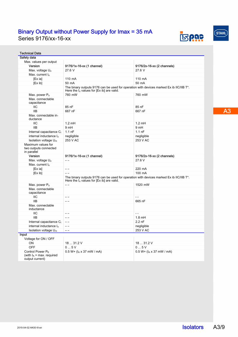
Technical DataSafety data
Max. values per outputVersion 9176/1x-16-xx (1 channel) 9176/2x-16-xx (2 channels)Max. voltage Uo 27.6 V 27.6 V Max. current Io
[Ex ia] 110 mA 110 mA [Ex ib] 50 mA 50 mA
The binary outputs 9176 can be used for operation with devices marked Ex ib IIC/IIB T*. Here the Io values for [Ex ib] are valid.
Max. power Po 760 mW 760 mW Max. connectable capacitance
IIC 85 nF 85 nFIIB 667 nF 667 nF
Max. connectable in-ductance
IIC 1.2 mH 1.2 mHIIB 9 mH 9 mH
Internal capacitance Ci 1.1 nF 1.1 nFinternal inductance Li negligible negligibleIsolation voltage Um 253 V AC 253 V AC
Maximum values for two outputs connected in parallel
Version 9176/1x-16-xx (1 channel) 9176/2x-16-xx (2 channels)Max. voltage Uo – – 27.6 VMax. current Io
[Ex ia] – – 220 mA [Ex ib] – – 100 mA
The binary outputs 9176 can be used for operation with devices marked Ex ib IIC/IIB T*. Here the Io values for [Ex ib] are valid.
Max. power Po – – 1520 mW Max. connectable capacitance
IIC – – - -IIB – – 665 nF
Max. connectable inductance
IIC – – - -IIB – – 1.8 mH
Internal capacitance Ci – – 2.2 nFinternal inductance Li – – negligibleIsolation voltage Um – – 253 V AC
InputVoltage for ON / OFF
ON 18 ... 31.2 V 18 ... 31.2 VOFF 0 ... 5 V 0 ... 5 V
Control Power PE (with IA = max. required output current)
0.5 W+ (IA x 37 mW / mA) 0.5 W+ (IA x 37 mW / mA)
Binary Output without Power Supply for Imax = 35 mASeries 9176/xx-16-xx
Isolators 2015-04-02·AK00·III·enA3/10
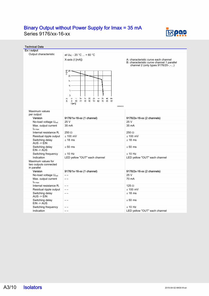
Ex i outputOutput characteristic
Maximum values per output
Version 9176/1x-16-xx (1 channel) 9176/2x-16-xx (2 channels)No-load voltage Uout 25 V 25 VMax. output current IA max
35 mA 35 mA
Internal resistance Ri 250 Ω 250 ΩResidual ripple output ( 100 mV ( 100 mV Switching delay AUS -> EIN
( 18 ms ( 18 ms
Switching delay EIN -> AUS
( 50 ms ( 50 ms
Switching frequency ( 10 Hz ( 10 Hz Indication LED yellow "OUT" each channel LED yellow "OUT" each channel
Maximum values for two outputs connected in parallel
Version 9176/1x-16-xx (1 channel) 9176/2x-16-xx (2 channels)No-load voltage Uout – – 25 VMax. output current IA max
– – 70 mA
Internal resistance Ri – – 125 ΩResidual ripple output – – ( 100 mV Switching delay AUS -> EIN
– – ( 18 ms
Switching delay EIN -> AUS
– – ( 50 ms
Switching frequency – – ( 10 Hz Indication – – LED yellow "OUT" each channel
Technical Data
at UN; - 20 °C ... + 60 °CX-axis (I [mA]) A: characteristic curve each channel
B: characteristic curve channel 1 parallel channel 2 (only types 9176/20-..-...)
09884E00

Binary Output without Power Supply for Imax = 43 mASeries 9176/xx-17-xx
Isolators A3/112015-04-02·AK00·III·en
A3
A3
A3
A3
A3
A3
A3
A3
A3
A3
A3
A3
A3
A3
Series 9176/xx-17-xx
Technical DataSafety data
Max. values per outputVersion 9176/1x-17-xx (1 channel) 9176/2x-17-xx (2 channels)Max. voltage Uo 27.6 V 27.6 V Max. current Io
[Ex ia] 60 mA 60 mA Max. power Po 415 mW 415 mW Max. connectable capacitance
IIC 85 nF 85 nFIIB 667 nF 667 nF
Max. connectable inductance
IIC 6.6 mH 6.6 mHIIB 40 mH 40 mH
Internal capacitance Ci 1.1 nF 1.1 nFinternal inductance Li negligible negligibleIsolation voltage Um 253 V AC 253 V AC
Maximum values for two outputs connected in parallel
Version 9176/1x-17-xx (1 channel) 9176/2x-17-xx (2 channels)Max. voltage Uo – – 27.6 VMax. current Io
[Ex ia] – – 120 mA Max. power Po – – 830 mW Max. connectable capacitance
IIB – – 665 nFMax. connectable inductance
IIB – – 7.5 mHInternal capacitance Ci – – 2.2 nFinternal inductance Li – – negligibleIsolation voltage Um – – 253 V AC
InputVoltage for ON / OFF
ON 18 ... 31.2 V 18 ... 31.2 VOFF 0 ... 5 V 0 ... 5 V
Control Power PE(with IA = max. required output current)
0.5 W+ (IA x 37 mW / mA) 0.5 W+ (IA x 37 mW / mA)

Binary Output without Power Supply for Imax = 43 mASeries 9176/xx-17-xx
Isolators 2015-04-02·AK00·III·enA3/12
Ex i outputOutput characteristic
Maximum values per output
Version 9176/1x-17-xx (1 channel) 9176/2x-17-xx (2 channels)No-load voltage Uout 25 V 25 VMax. output current IA max
43 mA 43 mA
Internal resistance Ri 460 Ω 460 ΩResidual ripple output ( 100 mV ( 100 mV Switching delay AUS -> EIN
( 18 ms ( 18 ms
Switching delay EIN -> AUS
( 50 ms ( 50 ms
Switching frequency ( 10 Hz ( 10 Hz Indication LED yellow "OUT" per channel LED yellow "OUT" per channel
Maximum values for two outputs connected in parallel
Version 9176/1x-17-xx (1 channel) 9176/2x-17-xx (2 channels)No-load voltage Uout – – 25 VMax. output current IA max
– – 86 mA
Internal resistance Ri – – 230 ΩResidual ripple output – – ( 100 mV Switching delay AUS -> EIN
– – ( 18 ms
Switching delay EIN -> AUS
– – ( 50 ms
Switching frequency – – ( 10 Hz Indication – – LED yellow "OUT" per channel
Technical Data
at UN; - 20 °C ... + 60 °CX-axis (I [mA]) A: characteristic curve each channel
B: characteristic curve channel 1 parallel channel 2 (only types 9176/20-..-...)
12019E00

Binary Output without Power SupplySeries 9176
Isolators A3/132015-04-02·AK00·III·en
A3
A3
A3
A3
A3
A3
A3
A3
A3
A3
A3
A3
A3
A3
Series 9176
Technical DataElectrical data
Auxiliary power withoutGalvanic separation
Test voltageacc. to standard EN 60079-11Ex i output to input 1.5 kV ACEx i outputs to each other 500 V ACacc. to standard EN 50178Inputs to each other 350 V AC
Electromagnetic compatibility Tested under the following standards and regulations: EN 61326-1 Use in industrial environment; NAMUR NE 21
Ambient conditionsAmbient temperature
Single device -20 ... +70 °CGroup assembly -20 ... +60 °C
The installation conditions affect the ambient temperature.Observe the "Cabinet installation guide".
Storage temperature -40 ... +80 °C Relative humidity (no condensation) ( 95 %
Electrical connectionConnection diagram 1 channel
06869E01
2 channels
06712E01
active
Hazardous area Safe area
Field device ISpac Isolator Control system
Division 1Zone 0 / 1
Division 2Zone 2
Field Device ISpac Isolator Control System
Division 1Zone 0 / 1
Division 2Zone 2
active
Hazardous area Safe area
active

Binary Output without Power SupplySeries 9176
Isolators 2015-04-02·AK00·III·enA3/14
Mechanical dataConnection
Weight approx. 160Mounting type on top hat rail (NS35/15, NS35/7.5) or in pac-CarrierMounting orientation horizontal or verticalEnclosure IP30Terminals IP20Enclosure material PA 6.6Fire resistance (UL-94) V0
Dimensional Drawings (All Dimensions in mm [inch]) - Subject to Alterations
09685E00
We reserve the right to make alterations to the technical data, dimensions, weights, designs and products available without notice. The illustrations cannot be considered binding.
Technical Data
Screw-type terminals Spring-type terminalsSingle-wire connection- rigid- flexible- flexible with core end sleeves (without / with plastic sleeve)
0.2 ... 2.5 mm2
0.2 ... 2.5 mm2
0.25 ... 2.5 mm2
0.2 ... 2.5 mm2
0.2 ... 2.5 mm2
0.25 ... 2.5 mm2
Two-wire connection- rigid- flexible- flexible with core end sleeves
0.2 ... 1 mm2
0.2 ... 1.5 mm2
0.25 ... 1 mm2
- -- -0.5 ... 1 mm2
X
122 m
m / 4
.80
"
114,5
mm
/ 4
.51
"
99 mm / 3.90 "17,6 mm / 0.69 "
Dimension XScrew-type terminals 108 mm / 4.25Spring-cage terminals 128 mm / 5.04