BIM Standard for Construction. BIM STANDARD FOR CONSTRUCTION I NTRODUCTION The current document...
72
BIM Standard for Construction Engineering Department Last Updated: 10/1/2019 Reviewed/Released 2019 v1.1
Transcript of BIM Standard for Construction. BIM STANDARD FOR CONSTRUCTION I NTRODUCTION The current document...

BIM Standard for Construction
Engineering Department
Last Updated: 10/1/2019 Reviewed/Released 2019 v1.1

Engineering Department Manual
BIM Standard for Construction
Last Updated: 10/1/2019 Page i Reviewed/Released 2019 v1.1
TABLE OF CONTENTS
1.0 BIM STANDARD FOR CONSTRUCTION ...................................................... 1
1.1 INTRODUCTION ....................................................................................................................... 1
1.2 PURPOSE ............................................................................................................................... 1
1.3 APPLICABILITY ....................................................................................................................... 1
1.4 USE OF THIS MANUAL ............................................................................................................. 1
1.5 GENERAL REQUIREMENTS ...................................................................................................... 3
1.5.1 LEVEL OF DEVELOPMENT (LOD) ............................................................................... 3
1.5.2 ROLES AND RESPONSIBILITIES .................................................................................. 3
1.5.3 SOFTWARE .............................................................................................................. 4
1.5.4 USE OF PARAMETERS ............................................................................................... 4
1.5.5 COMMUNICATION REQUIREMENTS.............................................................................. 5
1.5.6 BIM EXECUTION PLAN (BEP): ................................................................................ 10
1.5.7 BIM KEY DELIVERABLES .......................................................................................... 10
1.5.8 COORDINATE SYSTEMS .......................................................................................... 11
1.5.9 NAMING CONVENTIONS ........................................................................................... 11
2.0 SITE MODEL ....................................................................................... 12
2.1 INTRODUCTION ..................................................................................................................... 12
2.2 GOALS AND USES OF THE SITE MODEL .................................................................................. 12
2.2.1 INTENDED USES BY THE PANYNJ ........................................................................... 12
2.2.2 USES BY THE CONTRACTOR .................................................................................... 13
2.2.3 SITE LOGISTICS MODEL LIFECYCLE ......................................................................... 13
2.2.4 SITE LOGISTICS MODEL REQUIREMENTS .................................................................. 15
3.0 CONSTRUCTION MODEL ....................................................................... 18
3.1 INTRODUCTION ..................................................................................................................... 18
3.2 GOALS AND USES OF THE CONSTR. MODEL ........................................................................... 18
3.2.1 USES BY THE CONTRACTOR: ................................................................................... 18
3.3 OBJECT OF THIS SECTION ...................................................................................................... 19
3.4 CONSTRUCTION MODEL BREAKDOWN .................................................................................... 19
3.4.1 CONSTRUCTION MODEL MILESTONES ...................................................................... 19
3.4.2 AREAS OF INTEREST (AOIS) ................................................................................... 20
3.4.3 RELATION BETWEEN CM MILESTONES, AOIS AND MDS ........................................... 20
3.5 BIM COORDINATION PROCESS .............................................................................................. 21

Engineering Department Manual
BIM Standard for Construction
Last Updated: 10/1/2019 Page ii Reviewed/Released 2019 v1.1
3.5.1 OVERALL WORKFLOW ............................................................................................. 21
3.5.2 BIM COORDINATION PROCESS DEFINITION .............................................................. 21
3.5.3 POTENTIAL SCENARIOS AND BASIC WORKFLOWS ...................................................... 22
3.5.4 COORDINATION MEETINGS ...................................................................................... 26
3.5.5 COORDINATION SIGN-OFF ....................................................................................... 26
3.5.6 RECOMMENDED BEST PRACTICES FOR SPATIAL COORDINATION ................................ 27
3.6 FEDERATED MODEL SPECIFIC REQUIREMENTS (NWF/NWD) .................................................. 28
3.6.1 PROJECT BREAKDOWN INTO MULTIPLE FEDERATED MODELS .................................... 29
3.6.2 REFERENCE VIEWPOINTS ....................................................................................... 29
3.6.3 FOLDER STRUCTURE .............................................................................................. 30
3.6.4 SEARCH SETS ........................................................................................................ 30
3.6.5 APPEARANCE PROFILER .......................................................................................... 30
3.7 RFI TRACKING ...................................................................................................................... 32
3.8 REPORTING TO THE AUTHORITY ............................................................................................ 33
3.9 MODELING GUIDELINES BEST PRACTICES ............................................................................... 33
4.0 4D MODEL ......................................................................................... 34
4.1 INTRODUCTION ..................................................................................................................... 34
4.2 PURPOSE OF THIS SECTION ................................................................................................... 34
4.3 USES AND APPLICATIONS OF THE 4D ..................................................................................... 34
4.4 TYPICAL 4D SUBMISSION PROCESS........................................................................................ 34
4.5 4D MODEL REQUIREMENTS ................................................................................................... 35
4.5.1 CONSTRUCTION MODEL (NATIVE FILES) ................................................................... 35
4.5.2 SCHEDULE SETUP ................................................................................................... 36
4.5.3 4D ANIMATION (VIDEO FILE) .................................................................................... 36
4.5.4 4D MODEL ............................................................................................................. 37
4.5.5 4D MODEL AND SIMULATION REPORT ....................................................................... 37
4.6 4D MODEL ASSEMBLY – SUGGESTED WORKFLOW USING NAVISWORKS .................................. 37
5.0 AS-CONSTRUCTED MODEL .................................................................. 40
5.1 PURPOSE AND OBJECTIVES .................................................................................................. 40
5.1.1 INTENDED USES BY THE PANYNJ ........................................................................... 40
5.1.2 POTENTIAL USES BY THE CONTRACTOR ................................................................... 40
5.2 BASIC DEFINITIONS AND CLASSIFICATIONS ............................................................................. 40
5.2.1 REAL WORLD CONDITIONS ...................................................................................... 40
5.2.2 DATA TYPES: THE AUTHORITY RECOGNIZES TWO BASIC TYPES OF INFORMATION: ...... 40

Engineering Department Manual
BIM Standard for Construction
Last Updated: 10/1/2019 Page iii Reviewed/Released 2019 v1.1
5.2.3 LEVEL OF ACCURACY (LOA) ................................................................................... 41
5.2.4 TERRESTRIAL LASER SCAN (TLS) ........................................................................... 41
5.2.5 REQUIREMENTS ..................................................................................................... 41
5.2.6 FINAL SUBMISSION AND APPROVAL .......................................................................... 44
ANNEX A .................................................................................................... 46

Engineering Department Manual
BIM Standard for Construction
Last Updated: 10/1/2019 Page I Reviewed/Released 2019 v1.1
DOCUMENT CONTROL Document History
Version Issue Date Author Details of Changes
2019 v1.1 Z. Whiteman Formatting changes to Annex A

Engineering Department Manual
BIM Standard for Construction
Last Updated: 7/1/2019 Page 1 Reviewed/Released 2019 v1.1
1. BIM STANDARD FOR CONSTRUCTION
INTRODUCTION The current document describes requirements, processes and procedures currently demanded and in use by The Port Authority of New York and New Jersey in relation to use of BIM in Stage IV: Construction, particularly for a traditional Design-Bid-Build project delivery method.
PURPOSE As an owner, it is of paramount importance for the Agency that projects are delivered on time and within budget, keeping delays on Site to a minimum, facilitating project controls and maximizing the use of preventive actions over corrective actions. Clear, consistent and reliable information is critical for obtaining these goals. Thus, it is the main objective of this section to provide the proper framework for all Stakeholders to be able to deliver and receive consistent information throughout construction.
Secondarily, it is the Authority’s intention to further streamline the exchange of data across multiple stages of the project, beyond construction.
In general terms, this section aims to facilitate:
• Reutilization of information available from Stages I-III • Standardization and assurance of information developed in Stage IV, for analysis. • Preparation of final deliverables to the Authority, for records and further use in Stage V:
Operations and Maintenance.
APPLICABILITY Latest version of this document is mandatory to all Construction projects where BIM has been made a requirement by The Port Authority. Albeit it is not its purpose to rule aspects regarding BIM outside of Construction, it may provide guidance for application and implementation outside that project phase.
USE OF THIS MANUAL The current document is but a sub-component of a larger, agency wide BIM requirement and standard. An overall understanding of the requirements common to all Stages is recommended before in-depth study or reference of this section. Requirements made in the E/A Design Division BIM Standard are still applicable, unless explicitly overruled by this section.
Given the very nature of the Agency’s activity and structure, a wide variety of Construction projects may result of its activity. While requirements made on this manual are mandatory, it is not feasible to cover every possible scenario, which is why Program and/or Project Specific requirements may be made by the Authority. These will in turn, supersede any requirements made herein.
Changes in requirements may also be requested by the Contractor at the project level, but will only be effective once explicitly approved by the PANYNJ.
Any deviations from this standard must be documented in the Project BIM Execution Plan, which shall be the definitive document ruling the BIM aspects of the project.
Error! Not a valid bookmark self-reference. shows the hierarchy of the different documents that rule over BIM requirements for any given project.

Engineering Department Manual
BIM Standard for Construction
Last Updated: 7/1/2019 Page 2 Reviewed/Released 2019 v1.1
EAD BIM Standards
BIM Standards for Construction
Project specific requirements
BIM Execution Plan (BEP)
PANYNJ approved changes
Program BIM Requirements
+
DOCU
MEN
TATI
ON
HEI
RARC
HY
-
Figure 1-1

Engineering Department Manual
BIM Standard for Construction
Last Updated: 7/1/2019 Page 3 Reviewed/Released 2019 v1.1
GENERAL REQUIREMENTS
1.5.1 LEVEL OF DEVELOPMENT (LOD)
The Port Authority of New York and New Jersey adopts the LOD definitions as stated in the BIM Forum’s 2018 LOD Specification (Part I), publicly available at https://bimforum.org/lod/
This document shall be used along with the project specific Model Development Specification (MDS) prepared by the Port Authority. The MDS is a document containing the minimum LOD requirement that Model categories must meet, for each construction milestone. Additionally, it provides a summary of attributes/parameter information that shall be incorporated to the geometry.
A “base” PANYNJ MDS will be provided at the Project BIM Kick-off meeting. Contractor shall incorporate this specification as an annex to their BIM Execution Plan.
1.5.1.1 CURRENT AND TARGET LOD
As means to track levels of development achieved, two different parameters will be used: Current LOD, and Target LOD. MDS always refers to the latter. For more information on the implications and use of these parameters refer to 3.4
1.5.2 ROLES AND RESPONSIBILITIES
1.5.2.1 BIM LEAD COORDINATOR (BLC)
Person designated by the Contractor to:
• Lead and collaboratively work with the Contractor and Subcontractors in the development of a BIM Execution Plan (BEP) that can respond to the specific needs of the project.
• Facilitate information and provide guidance on BIM requirements, processes and procedures to the Contractor staff and each of the Subcontractor BIM Coordinators. Notify the BIM Support Group of any information request regarding BIM.
• Act as liaison between the PANYNJ’s BIM support group and BIM Coordinators. • Monitor the integrity of all models developed by the Subcontractors, as well as model and
processes adherence to the BEP and PANYNJ BIM Standard (Quality Assurance and Quality Control).
• Host and lead multi-trade spatial coordination meetings, which includes but may not be limited to present the issues to review, record the meeting conclusion and distribute clash report to interested parties, pursue resolution of conflicts.
• Work with Contractor’s designated scheduler and estimator to obtain a 4D and 5D model representative of the Project’s cost-loaded schedule on each of their submissions.
• Coordinate efforts to comply with the submissions as requested by the Authority. Meet with the BIM Support Group designated representative at regular intervals to present progress as well as comments from returned submissions.
1.5.2.2 BIM COORDINATORS (BCS)
Person designated by each Subcontractor to:
• Collaborate on the development of the BEP, if requested by the BLC. • Facilitate information and provide guidance on BIM requirements, processes and procedures to
the Subcontractor staff and BIM Users. Notify the BIM Lead Coordinator of any information request regarding BIM.

Engineering Department Manual
BIM Standard for Construction
Last Updated: 7/1/2019 Page 4 Reviewed/Released 2019 v1.1
• Act as liaison between the BLC and the BIM Users. • Supervise authored model development and their updates adherence to the requirements made
on the BEP and PANYNJ BIM Standards. • Represent Subcontractor on BIM Coordination Meetings when requested, provide assessment on
conflicts and communicate to the BIM Users the action items. • Collaboratively work with field personnel to define the methods and processes that will be used to
keep models updated with field-verified information (As-Constructed updates)
1.5.2.3 BIM AUTHORS
Generally speaking, the person or persons authorized to perform any modifications on the Models, on either their native format (Revit and Civil 3D) or the exported versions (Navisworks). They are required to:
• Follow modeling guidelines and best practices as stated in the PANYNJ BIM Standards. • Perform all works as outlined in the BEP. • Elevate to the responsible BIM coordinator (or the BLC, if no BC has been appointed) any
questions, doubts, comments and/or suggestions in regards to BIM procedures and deliverables.
1.5.2.4 BIM/CAD SUPPORT GROUP (PANYNJ) • Assist the Engineer on monitoring continuous adherence to the BIM Standards in the project. • Facilitate information and provide guidance on BIM requirements, processes and procedures to
the Contractor’s appointed BLC, particularly regarding interpretation of the BIM standard. • Meet with the Contractor’s designated BLC at regular intervals to review progress and discuss
action items to guarantee adherence to the BIM Standard and BEP. • Keep record of all required action items that are result of interactions involving BIM methodology
between Contractor and the Authority. These interactions include (but may be not limited to) ordinary and extra-ordinary model reviews and BIM-related RFIs addressed to the Authority.
1.5.2.5 BIM USERS
Any individual or party with access to Models with the purpose of examining it and/or obtaining information from it but without modifying its contents. They shall:
• Obtain the proper clearance and authorization to access BIMs, as some of the information might be confidential.
• Do not alter the Models in any way. If there are observations or corrections to be made, procedure for communicating this shall be as described in the BEP.
1.5.3 SOFTWARE
Approved software and versions shall be as stated in the EAD BIM Standard Manual.
1.5.4 USE OF PARAMETERS
The appropriate use of parameters is critical to meet the purpose of the different models. A variety of parameters have been included in the Revit templates for Construction, and are referenced in the sections corresponding to each of the BIM deliverables, as defined in 1.5.7.

Engineering Department Manual
BIM Standard for Construction
Last Updated: 7/1/2019 Page 5 Reviewed/Released 2019 v1.1
1.5.4.1 SHARED PARAMETERS
In order to ensure information in the Revit Models is exchanged as seamlessly as possible between different Software platforms and Stakeholders, PANYNJ’s Shared Parameter file must be used at all times.
Shared Parameters referred to in this Section, can be located in the Construction parameter group, as shown.
Shared Parameter file may be altered by the Contractor, as long as the procedure described in is 1.5.4.2 followed.
1.5.4.2 PROCEDURE TO ADD PARAMETERS
Contractor may need to add new parameters, based on project specific needs. In such case, the following procedure shall be followed:
1 Contractor’s BIM Lead Coordinator (BLC) shall communicate to the Authority the need of a new Parameter or group of parameters.
2 BLC shall specify the proposed name and purpose for the new parameters, as well as the Revit Categories it will be applicable to and the potential values it may contain.
3 The PANYNJ will decide if the parameter is in fact necessary, and if is to be a shared parameter or not.
4 For shared parameters, the Contractor’s BLC will supervise the correct inclusion of the parameter to the project and the shared parameter files.
5 BLC will submit to the PANYNJ the modified shared parameter file for review and record.
1.5.5 COMMUNICATION REQUIREMENTS
Effective communication is critical to the success of any project. To that end, the PANYNJ requires certain BIM related meetings are held regularly between Contractor and the Authority. Additionally, certain documents supporting these meetings are to be timely prepared and submitted.
Both meetings and documentation are meant to help guarantee that:
• There is a unified and consistent understanding of progress made by the Contractor on BIM. • Needs of the project and different stakeholders are properly understood by the correct people. • Action items can be defined and assigned to a responsible party
Figure 1-2

Engineering Department Manual
BIM Standard for Construction
Last Updated: 7/1/2019 Page 6 Reviewed/Released 2019 v1.1
• Those action items can be traced (and enforced if necessary) until closure.
1.5.5.1 MEETINGS
Different meeting types and content shall be in general terms as described below.
1.5.5.1.1 BIM Kick-off Meeting
Goals: • Introduce the different parties that will be taking a major role on BIM processes, and stablish
the communication procedures and channels to be used throughout the project. • Establish a common understanding of and buy-in to the BIM goals for the project. • Establish consensus regarding the BIM uses that will be employed on the project. • Establish a common understanding of the Project-specific requirements and procedures
regarding BIM methodology and deliverables. • Ensure Contractor has sufficient information to begin preparation of initial BIM deliverables. • Define deadlines for initial submissions
Date:
To be coordinated by the Resident Engineer’s office, within the time frame typically stablished by Contract. This meeting is of a single occurrence.
Location:
This meeting will be held on-site. If for some reason this cannot be arranged, the PANYNJ will provide an alternative location. Local, physical presence is required for all mandatory attendees (refer list below).
Attendees (Mandatory): • Contractor’s Project Manager. • Contractor’s BIM Lead Coordinator. • Contractor’s Scheduler. • Resident Engineer. • PANYNJ’s BIM Support Group representative.
Attendees (Optional): • Construction Management Division (CMD) representatives. • PANYNJ’s appointed Scheduler. • Others, as the Authority sees fit.
Tentative agenda: • Roll Call/Taking of attendance, and personal introductions (2-5 minutes) • Presentation of BIM use in the Agency (Optional, 5-7 minutes) • BIM Goals for the project (5 minutes) • BIM Uses to be employed on the project (10 Minutes) • Review of Project-specific BIM requirements. (10-15 Minutes)

Engineering Department Manual
BIM Standard for Construction
Last Updated: 7/1/2019 Page 7 Reviewed/Released 2019 v1.1
o Contract Language o Project-specific Model Development Specification (MDS)
• BIM Information handover and discussion (5-7 minutes). This may include: o Site Model o Project-specific RVT Templates o Editable Report Templates. Refer 1.5.5.2 o Editable Model Development Specification (MDS) o Other as needed for that specific project
• Deadlines: the following dates shall be defined (within the margins stated on the Contract) o Submission of BIM Execution Plan, by the Contractor. Refer Annex A o Submission of Basis of Design (BOD) Model, by the Contractor. Refer 3.0 Construction
Model o Submission of updated Site Model, by the Contractor. Refer 2.0 Site Model o Initial submission of 4D Model, by the Contractor. Refer 4.0 4D Model
• Define acceptable file transfer protocol.
Definitive agenda will be submitted by the Authority at a minimum of two working days prior to the meeting.
Meeting Minutes and records:
All agreements, outstanding questions and action items discussed in the meeting shall be recorded by the BIM support group in the BIM Kick-off meeting minutes. Minutes will be distributed to all attendees no later than two working days after meeting was held.
1.5.5.1.2 BIM Progress Meetings
General goals: • Review progress made on BIM deliverables since last submission, verifying model(s) against
Project MDS. • Discuss outstanding issues, RFIs, action items and non-compliances on BIM-related subjects. • Ensure Contractor has all required information and full understanding of the requirements
made, to guarantee successful future BIM submissions.
Frequency: One week before BIM submission by the Contractor, starting from the BIM Kick-off meeting till the final As-Constructed model is accepted by the Authority. If for some reason there is delay on BIM submission, these meetings will be scheduled every 14 calendar days until the situation is normalized.
Potential locations: On-site meeting is recommended. Alternatively, remote attendance is possible. If the Authority finds it necessary, site presence may be deemed mandatory.
It is critical that deviations from the BIM standard as discussed and accepted during this meeting (if any) are registered in the minutes. This record document is of paramount importance in the preparation of the BEP.

Engineering Department Manual
BIM Standard for Construction
Last Updated: 7/1/2019 Page 8 Reviewed/Released 2019 v1.1
Typical Attendee list: • Contractor’s BLC. • Contractor’s Project Manager. • PANYNJ’s BIM Support group representative. • CMD appointed staff.
Tentative Agenda: to be defined case by case, depending of specific project needs at the time.
Minutes/Records: typically recorded on the BIM Submission Log, a record kept by the PANYNJ’s BIM support group and issued as part of the formal response to each Contractor’s BIM submission. Meeting minutes with specific action items may also be distributed by the Authority when necessary.
1.5.5.1.3 BIM Submission Review meetings
Goals: • Discuss submission results as reviewed by the Authority’s BIM Support group. • Review action items as registered in the BIM Submission Log.
Frequency: • From 3 to 5 working days after the Authority submits its response and comments made over
the Contractor’s BIM submission.
Potential locations: same as BIM Progress Meetings.
Typical Attendee list: same as BIM Progress Meetings. Additionally, • Contractor’s Scheduler. • CMD Scheduler.
Tentative Agenda: same as BIM Progress Meetings.
Minutes/Records: same as BIM Progress Meetings.
1.5.5.1.4 BIM Coordination Meeting
A special type of meeting, recurrently held between trade Sub-Contractors and the Contractor, with the main purpose of clearing interferences (clashes) in the Construction Model and review overall progress. Contractor is to provide location for meeting to take place, as well as decide on agenda, frequency of meetings and other similar aspects. PANYNJ representatives reserve the right to attend these meetings as observers, prior requesting an invitation from Contractor. For more information on BIM Coordination refer to 3.5 BIM Coordination Process.

Engineering Department Manual
BIM Standard for Construction
Last Updated: 7/1/2019 Page 9 Reviewed/Released 2019 v1.1
1.5.5.1.5 Typical four-week meeting recurrence
Figure 1-3
Note: frequency of meeting may differ depending on needs of the project.
1.5.5.2 SUPPORTING DOCUMENTATION
Table 1-1 shows a summary of typical documentation that will be exchanged between the Authority and the Contractor throughout the project. More specific reports may be required depending on the project.
Refer to Annex A for reference on each of the documents defined in this section. Editable versions of said templates will be provided at the BIM kickoff meeting for Contractor to use throughout the project.
Table 1-1
Prepared by Addressed to Triggers Submission Essential contents
BIM Execution Plan (BEP)
Contractor BIM Support Group • Project Start (BIM Kick off meeting)
• Changes in processes • Changes in Staff • As requested by the
PANYNJ.
• Project specific BIM regarding BIM • Roles and responsibilities •
Progress Report Contractor BIM Support Group • All BIM submissions. • When requested by the
Authority
• Overall description of progress since last submission on all major deliverables (Construction Model, 4D/5D, etc.).
• LoD achieved on the construction model, as per MDS and BEP
• New deviations from the Standard and recommended practices, if any, with proper justification
• Clash Report, showing Coordination status and clash count per zone, open RFIs, etc.
• Issues encountered, specifically those that prevent the submission

Engineering Department Manual
BIM Standard for Construction
Last Updated: 7/1/2019 Page 10 Reviewed/Released 2019 v1.1
requirements to be met by the Contractor or Subs.
BIM Submission review log
BIM Support Group
Contractor Scheduled BIM Submissions
• Record of comments and observations made by the authority.
• Responses by the Contractor
Model Quality Checklists
BIM Support Group
Contractor Scheduled BIM Submissions
• Detail of BIM review results, with pass/fail status.
1.5.5.3 DATA EXCHANGE PROTOCOLS
Models, drawings, reports and any other digital file exchange between Contractor and the PANYNJ shall be made by the Authority’s approved platform or service. The specific protocols for each project will be discussed at the BIM kick-off meeting, and properly documented on the BEP.
1.5.6 BIM EXECUTION PLAN (BEP):
At the start of every new BIM project, a BEP must be submitted to the Port Authority BIM / CAD support group. Refer Annex A
Once approved by the Authority, BEP shall become the ultimate compendium on BIM requirements, methodologies and workflow for a specific project.
The BEP is considered a “living” document, in the sense that it will likely be updated throughout the project. Situations that may trigger a revision on the BEP by the Contractor include, but are not limited to:
• Changes in Staff, that directly affect the BIM processes and/or deliverables • Changes in processes • Changes in requirements • Changes in BIM Schedule (Coordination sign-off dates, LOD milestones, etc.) • If required by the Port Authority
1.5.7 BIM KEY DELIVERABLES
This section contains only high-level description of the main deliverables expected from the Contractor. Refer separate sections for details.
1.5.7.1 SITE MODEL (PLANNING AND LOGISTICS MODEL)
Digital 3D representation of the Work containing information regarding Construction activities other than the finished and final work (e.g. Fencing, Traffic Control where applicable, excavation works, Job trailer location, crane positions, etc.). Definitions and requirements are separated for practical and applicability purposes, but this model may or may not be integrated with the Construction Model.
1.5.7.2 CONSTRUCTION MODEL
Digital 3D representation of the Work mostly containing information about final and finished work, although some temporary elements may be represented as well if found convenient (e.g. for coordination purposes) by the Contractor. The Contractor will be responsible for continually updating this model throughout
Engineering Department Manual
BIM Standard for Construction
Last Updated: 7/1/2019 Page 11 Reviewed/Released 2019 v1.1
construction so it always reflects the latest information available, including but not limited to: Shop Drawings, Approved Submittals and cut-sheets, field verification, Post Awards Contract Changes (PACCs).
1.5.7.3 4D MODEL
Digital representation of the Work, integrating the Construction Model with the cost-loaded construction Schedule. With each schedule update submitted to the Authority, the Contractor shall also submit an updated 4D Model based on the latest version of the Construction Model and the revised schedule.
1.5.7.4 AS-CONSTRUCTED MODEL AND POINT CLOUD DATA.
The As-Constructed Model shall be considered the final version of the Construction Model, which incorporates both field verified locations and geometry for all Model components, as well as Asset information as requested by the Port Authority.
Registered Point Clouds, when required by Contract, shall also be delivered to the Authority on intervals that are project-specific. Whilst Point Cloud data may be submitted several times during the duration of Work, the As-Constructed Model as such will be submitted only once at the end of the project, for review and approval. This Model is of paramount importance to the Authority, and its approval is a mandatory requirement for achieving Project close-out and handover.
1.5.8 COORDINATE SYSTEMS
For all Port Authority of NY & NJ projects, the default horizontal coordinate systems are the State Plane NAD83 New York East and Long Island Foot systems. The default vertical system is the State Plane NAVD 88 system. The LEA must determine at the beginning of a project if another coordinate system is to be used. The project coordinate system will be established in the BIM Site Model file provided by The Port Authority of NY & NJ BIM Support Group.
1.5.9 NAMING CONVENTIONS
All electronic project information should be named following The Port Authority of NY & NJ EAD BIM Standard Naming Conventions, except where explicitly requested otherwise by the BIM for Construction Standard.

Engineering Department Manual
BIM Standard for Construction
Last Updated: 7/1/2019 Page 12 Reviewed/Released 2019 v1.1
2. SITE MODEL
INTRODUCTION BIM methodologies can assist construction activities and site logistics in various manners. Perhaps the most evident one, is to leverage on the powerful visualization provided by a 3D model that somehow represents temporary works, construction activities, hazards, etc.
Once construction activities start and end dates in relation to site geometry, a Construction Model (which Site Model is an important part of) becomes also a site planning and risk management tool.
In other words, the Site Model is a subcomponent of the Construction Model, and it needs to work in close relation to the schedule in order to develop its full potential and provide real value.
This section refers to the particularities of the Site Model, as a special case amongst all Models to be developed by the BIM authors.
It is also worth mentioning that, due to the types of project in the PANYNJ portfolio and their potential locations, Site Model requirements can greatly vary between projects. BIM Execution Plan as submitted to the Authority for review and approval, shall record all Site Model requirements particular to the project.
GOALS AND USES OF THE SITE MODEL As part of the Construction Model (CM), Site Model (SM) shares the same overall goals. Refer Goals and uses of the Constr. M. Specific goals pursued by the SM include:
• To support site planning and logistics. • To improve project safety. • To assist activities involving new Underground Utilities • To support Program management, when applicable.
The following uses intend to support these goals:
2.2.1 INTENDED USES BY THE PANYNJ
SM will be used for:
Contextual analysis: by showing site surroundings, the Model will better mirror the real-world conditions, as no Construction project is impervious to the environment in which it transpires. Access roads and logistic, impact on vehicle or pedestrian traffic, are some of the studies that can be performed.
Assisting on Program planning: by containing a unified coordinate system, a particular project can be incorporated in a Program-level Construction Model, rather seamlessly. This allows to analyze how different project interact with each other.
Improving site safety: by incorporating geometry and schedule, some major hazards can be simulated in time, and preventive or mitigation actions can also be defined for specific dates.
Reference of existing underground utilities, when available: by incorporating existing site utilities into de starting Site Model, as provided by the Authority.
Systematic Revision of 4D Site Plans: by incorporating project schedule, a more comprehensive analysis on construction activities and their repercussions can be performed.

Engineering Department Manual
BIM Standard for Construction
Last Updated: 7/1/2019 Page 13 Reviewed/Released 2019 v1.1
Logistics Planning: The 4D site model is invaluable in planning logistics issues such as access and egress routes for materials, traffic shutdowns, use of lay-down space, etc. This tool is especially useful on tightly constrained project sites.
2.2.2 USES BY THE CONTRACTOR
For the Model to fulfil the uses envisioned by the Authority, as defined in 2.2.1, it is the Contractor’s responsibility to develop and maintain the SM, from the starting Model as provided by the PANYNJ’s BIM support group. Said Model shall comply with to the general requirements made herein, and documented on the BEP.
Furthermore, the PANYNJ believes there are other potential uses that may provide value to the Contractors and Subcontractors. In this spirit, the Authority encourages all parties to:
Use SM to support and improve the efficiency of the site layout: from the visualization standpoint alone, the Model may provide a different perspective to consider alternate possible layouts (location of trailer, access to site and material lay down, etc.)
Use Model for preliminary hazard detection and safety planning
Analysis of construction activities sequence: either by a human operator or a computer-based application, which may reveal new threats or opportunities, previously overlooked.
2.2.3 SITE LOGISTICS MODEL LIFECYCLE
As stated before, Site Model has some unique issues compared to other models developed by the BIM Authors. One of these special features is the unique life cycle that it follows. Refer Error! Reference source not found. for reference.
Whilst typically all Model templates provided by the Authority will be empty “container” files, Site Model will have some basic content already introduced by the PANYNJ’s BIM support group (refer 2.2.3.1).
During the BIM Kick-off meeting, the Site Model will be handed over to the Contractor’s BIM Lead Coordinator, who will take ownership of it. Only if the Site Model coordinates are incorrect, it may return to the Authority for amendment.
Throughout construction, the Contractor shall include elements as per requirements stated in this clause.
Finally, Site Model will be submitted to the Authority for record only (not approval) at project closeout. The reason that it is not submitted for final approval, is that the SM does not contain any final work*, only temporary. This means it does not contain information relevant for Operation and Maintenance. Refer 2.2.4 for content requirements.
*Note: if permanent improvements or modifications to the site are part of the Scope of Work, a separate Model will be created for this specific purpose. Site Model will continue to exist in this scenario, containing only temporary work as defined herein.
2.2.3.1 INITIAL SETUP AND HANDOVER TO CONTRACTOR
The starting Site Model (or Base SM) will be developed by the PAYNJ’s BIM support desk prior to the formal beginning of the Project.
This basic Model will contain the project coordinates to be used across all other models, for the rest of the Project.

Engineering Department Manual
BIM Standard for Construction
Last Updated: 7/1/2019 Page 14 Reviewed/Released 2019 v1.1
This is the only mandatory information that the Site Model must contain at the time of the Kick-off meeting, when it will be handed over to the Contractor.
Additionally, depending of the available information for a specific project, the model may also contain:
• Project specific design Models (Stage I-III)* • Topographical surface • Underground Utilities • Roads, roadways, bridges, pedestrian walkways and other traffic components. • “Blocks” representing buildings and structures within a certain radius from project limits. Radius
will depend on specific project surroundings.
*Important Disclaimer: Design Models provided by the Authority to Contractors are for visual information only. Each Contractor may decide to either share Design Models with Subcontractors, or withhold them for internal use and reference. In any case, Design Models may be used as a starting point for trade Construction Models at the Contractor’s own risk. The PANYNJ may not be held accountable for measurements, quantifications, coordination or any other activities and assumptions made based on the Design Models. It is strongly suggested that, if Contractor decides to use these for the processes and deliverables described in this Standard, they are thoroughly validated with all Contract information first (drawings, specifications, etc.).
The Site Model handover will occur at the BIM Kick-off meeting. A representative of the PANYNJ’s BIM Support Group will provide the Contractor with a digital copy of the files, present its contents to all attendees and provide information on any project particularities, when available.
2.2.3.2 VALIDATION AND DEVELOPMENT
Upon receipt of the base Site Model, Contractor must perform an assessment to determine if there is any information of particular importance that may require additional validation.
Contractor will modify the site model as needed based on this, by adjusting the elements previously included previously by the PANYNJ’s BIM Support Group and incorporating additional elements as described on 2.2.4.2
Unlike other Models (trade models) SM will not typically undergo a LOD transformation throughout the process, since it will mostly be elemental geometry acting as place holder for temporary works. Refer 2.2.4.
2.2.3.3 UPDATES
Contractor shall maintain the site model throughout the construction process by incorporating any major change in geometry, logistics or site layout. Additionally, Contractor is also responsible for keeping Model current in terms of Construction sequence.
2.2.3.4 SUBMISSION AND REPORTING TO THE AUTHORITY
First submission: Contractor will submit the SM for comment at a date defined at the BIM Kick-Off meeting. Given the low complexity of the Model and the benefits it can provide on the early stages of construction; an early submission will be required by the PANYNJ (i.e., before the trade Models).
Regular updates: Contractor will submit the SM with every regular Construction Model submission as stated on the BEP. Contrary to the trade Models, the Authority will not review the SM for BIM compliance. Regardless of the SM being submitted “For Record Only”, the BIM Support group reserves the right to request a submission for approval, if the Contractor fails to observe basic model quality and BIM management good practices (e.g. in regards to naming convention, size of families imported to the model, appropriate model categories, etc.).

Engineering Department Manual
BIM Standard for Construction
Last Updated: 7/1/2019 Page 15 Reviewed/Released 2019 v1.1
Reporting: Contractor shall include a basic narrative on the BIM report, whenever there is a significant change is made. There is no need to include a mention in the report when SM presents no modifications.
Figure 2-1 - Site Model Life Cycle
2.2.4 SITE LOGISTICS MODEL REQUIREMENTS
2.2.4.1 MODELING REQUIREMENTS
Unlike trade models, SM will not contain any final work and will not be migrated to the Agency’s Asset Management System. As a direct consequence, content requirements are fewer and less strict. However, the following practices are to be observed, at minimum:
• Contractor is always expected to follow PANYNJ BIM standards as a reference on SM content. • Template provided by the Authority will contain basic Worksets and custom materials as a
starting point. Contractor may create more at his own discretion, providing all color and Workset conventions are clearly stated in the BEP. Refer 2.2.4.2 for reference on elemental geometry.
• As a general rule, LOD requirements for elements in the SM will not be higher than a level of development “LOD-200” as understood and interpreted by the BIM Forum’s LOD Specification (Part I), version as stated in Section 1.5.1.
• No permanent work is to be included in the Site Model. • The Site Model must remain a Revit native file, and its geometry must also be native to this
software (there may be some approved exceptions, like imported Civil3D Pipe networks, that will be treated on a case-by-case scenario).

Engineering Department Manual
BIM Standard for Construction
Last Updated: 7/1/2019 Page 16 Reviewed/Released 2019 v1.1
• Elements Family Name and Type, when defined by the Contractor, must be suggestive to what they are representing.
• Categories used to represent any element should be the closest to as possible (a fence can technically be represented with a “Generic Element”, but using Revit’s “Wall” tool is recommended) Use of the “Model in place” tool to create geometry, is accepted in the SM (unlike trade models). Careful use is recommended.
• To avoid rework, consider the Project schedule requirements when creating content in the Site Model, as some elements extent may be limited by some activities duration (e.g.: activity duration limited to “x” days may determine how excavation geometry is modeled)
2.2.4.2 REPRESENTED ELEMENTS AND ENTITIES
Table 2-1 includes elements to be represented by the Contractor on the SM.
Guidelines are mere suggestions on acceptable representation. Contractor is encouraged to include more representative geometry when available (e.g., some cranes and other vehicles may be free content available from manufacturers).

Engineering Department Manual
BIM Standard for Construction
Last Updated: 7/1/2019 Page 17 Reviewed/Released 2019 v1.1
Table 2-1
ELEMENT MODELING GUIDELINE WORKSET – COLOR
Property line perimeter
Modeled as a single element, of negligible thickness and with an elevation equal to or higher than the top-most point of any temporary or final work
Site – Layout; White, Semi transparent
Job Trailers
Represented as simple prisms (overall dimensions)
Site – Layout; White, Semitransparent
Material lay down areas
(non-hazardous)
Represented as simple prisms (overall dimensions)
Site – Logistics; Gray, Semitransparent
Site access points Modeled as a single element, of negligible thickness. May overlap with fencing and property line geometry.
Site – Logistics; Gray, Semitransparent
Parking (temporary)
Modeled as single or multiple elements of arbitrary thickness. “Slab” tool is acceptable.
Site – Layout; White, Semitransparent
Fences Modeled as single or multiple elements of arbitrary thickness. “Wall” tool is acceptable.
Site – Layout; White, Semitransparent
Cranes, hoists and Fixed Equipment
Geometry must suggest the type of equipment when possible. Crane envelopes, equipment clearance and other “no-fly” zones must be represented
Site – Equipment; Orange, Solid (equipment)
Site – Equipment; Red, Semitransparent (envelopes and “no-fly” zones)
Excavation Basic prismatic shapes showing overall dimensions.
Site – Construction Activity; Red, semitransparent
Temporary Structures
Basic prismatic shapes showing overall dimensions.
Site – Construction Activity; White, Semitransparent
Contractor is encouraged to include also any other element that may be an additional part of the construction logistics and may affect the Project development and its surroundings, such as pedestrian paths, traffic, city areas, etc.

Engineering Department Manual
BIM Standard for Construction
Last Updated: 7/1/2019 Page 18 Reviewed/Released 2019 v1.1
3. CONSTRUCTION MODEL
INTRODUCTION In an attempt to keep the language simple, the concept of Construction Model may be used colloquially in this Section. Depending on context, “Construction Model” may refer to:
A single composite Model, e.g. the Navisworks NWF/NWD files.
Several Models, e.g. the aggregate of the Revit and Civil 3D native files; or
A single trade model (e.g. the electrical Construction Model).
Additionally, it is worth noting that the concept of Construction Model is not tied to a specific LOD, or progress status. Quite on the contrary, it is expected that both geometry and data change, and are progressively more defined as information becomes available.
GOALS AND USES OF THE CONSTR. MODEL Construction Model is, above all, a tool or instrument to facilitate information so more educated decisions can be made regarding the Project. As an owner, the PANYNJ considers the Model as a tool to facilitate:
• Risk mitigation, by providing reliable information earlier in time (compared to a non-BIM methodology)
• Project delivery on time, and within budget (for example, by minimizing Change Orders and Coordination-driven delays and rework in the field).
• More efficient site planning and logistics. • Improving project safety. • Data recollection on relevant assets, for future Operation needs.
3.2.1 USES BY THE CONTRACTOR: • Mandatory uses: Multi-trade space coordination and shop drawings creation, shall always be
directed by the Construction Model. Refer Section 3.5 for recommended processes that integrate BIM Coordination and shop drawings.
• Recommended uses: compliance with this Standard make the CM a data-rich model, with information about equipment, quantities and location, schedule and cost, etc. For this reason, the PANYNJ strongly encourages the Constructor to use the information available in all ways possible that may support the BIM goals, as stated above. Some of these uses may be:
o Support schedule analysis and decision-making, by leveraging on the visual impact of the 4D.
o Support QTO and Cost analysis by extracting quantities, volumes, etc. directly from the models.
The Construction Model is of a highly dynamic nature by the simple fact that it affects, and is in turn affected by, the construction process itself. In order for Model to meet its purpose, information contained in it must always be as current and as reliable as possible.

Engineering Department Manual
BIM Standard for Construction
Last Updated: 7/1/2019 Page 19 Reviewed/Released 2019 v1.1
o Support Site logistics and Safety planning, for example by visually assisting hazard management and planning off-site.
OBJECT OF THIS SECTION For simplicity, this section will focus on the mandatory uses the Contractor has to make of the Construction model, as stated on 3.2.1.
Site Logistics, 4D simulation and recording As-Constructed conditions are all uses of the Construction Model as well, which is why they are reminded here. However, their definitions and requirements are included in separate sections within this Standard.
CONSTRUCTION MODEL BREAKDOWN Since the Constr. Model is to correlate to the construction itself, different development statuses may coexist in the same model.
As an example, consider a two-story facility, where:
• Mechanical Room in the lower level has already been installed. Field verified locations have been recorded and incorporated into the model. Required asset information has also been confirmed in the different trade Models.
• The MEP+FP models on the lower level have all been modeled to the Target LOD, and the area has been signed off for coordination, but no installation has occurred.
• The upper level has been modeled as per Contract Documents, but has not been updated with manufacturer content (approved submittals) yet. Coordination is pending.
Clearly, stating that the Constr. Model is on one particular construction status and development stage is not possible.
In order to facilitate a common understanding of actual progress, the PANYNJ breaks down the CM under two concepts: Construction Model Milestones and Areas of Interest (AOIs)
3.4.1 CONSTRUCTION MODEL MILESTONES
These can be considered as a Constr. Model division in time. Model milestones will typically be the same for every project, and follow logical Construction sequence. These are defined by the Authority and cannot be changed.
In general terms, milestones are as defined as follows:
• Basis of Design (BOD): Models have been prepared as per Contract Documentation, plus any variation requested from or approved by the Authority (like PACCs, returned RFIs, approved Change requests). Regarding coordination, location of elements is approximate, not final.
• Coordination Sign-off model: trade models have reached the Target LOD, plus all elements are in their final position. Model is accepted as the “single source of truth” for coordination purposes. As part of the sign-off process, all parties agree to install layouts as shown on the model.
• As-Constructed Model: elements identified in the MDS have been updated as per field-verified locations. Additionally, information relevant to the Enterprise Asset Management System has been incorporated to the trade models. Refer Section 5.0 As-Constructed Model for requirements specific to the As-Constructed model data.

Engineering Department Manual
BIM Standard for Construction
Last Updated: 7/1/2019 Page 20 Reviewed/Released 2019 v1.1
3.4.2 AREAS OF INTEREST (AOIS)
AOI are a spatial division or breakdown of the project. These are defined by the Constructor, and stated in the BIM Execution Plan. Definition is typically influenced by the construction sequence, but other factors may become relevant as well. As a general rule, defined AOIs must include all trades occupying that space.
Examples of AOIs are entire Construction Zones, complete or partial Floors, Mechanical rooms, Generator/Electrical Rooms, Risers, Restrooms, Single rooms of particular importance, etc.
3.4.2.1 DEFINING AOIS
As mentioned before, the Contractor shall propose in the BEP the areas that the Construction Model will be broken into. AOIs are subject to approval by the Authority.
A few aspects to consider for this purpose:
• Each AOI will be considered by the Authority as a BIM partial deliverable. Reporting from the Contractor will be AOI based. Refer Annex A for BIM Progress report template.
• Naturally, the sum of the AOIs needs to contain the full scope of the Work. • AOIs will go through each Model Milestones independently*. • There is no limitation of how big or small a AOI needs to be in terms of square footage. • There is no minimum or maximum amount of AOIs that a project needs to have. • It is often helpful to think “backwards in time”. For example, to identify zones that will need shop
drawings first, so in-depth BIM coordination can begin sooner on said areas. *The Authority may request at its sole discretion that all AOIs are submitted for the BOD milestone at the same time. This may be the case for relatively small and simple projects like Parking garages, simple concrete bridges, small Ad-Hoc buildings, etc.
3.4.3 RELATION BETWEEN CM MILESTONES, AOIS AND MDS
The Model Development Specification (MDS) is closely related to the other two concepts presented. As mentioned before, each of the AOIs will typically go through the Milestone sequence independently, and will be considered as a partial delivery of the whole. Columns in the MDS under Construction Model define the Model Milestones discussed in this section.
Note that:
• The LOD stated for each category on each column, is the minimum accepted for that milestone. The Contractor may at his sole discretion, chose to model beyond the requested LOD.
• Strictly speaking, LOD definition includes coordination status, as it often refers to location of elements. For example, it is not correct to describe a pipe segment as LOD350 if it has outstanding interferences related to it, because it is likely that the element is not on its final position.
• As stated in 1.5.1, the Authority leverages on the concepts of Current LOD and Target LOD. In relation to the MDS, it should become apparent that Current LOD cannot be less than the Basis of Design LOD. In the same spirit, Target LOD is defined for each milestone by the MDS.
• In relation to the LOD, the division into AOIs is only to allow for scheduling and tracking development to the target LOD. The Level of Development as stated for each Milestones in the MDS must eventually be achieved uniformly across the entire Construction Model.
Engineering Department Manual
BIM Standard for Construction
Last Updated: 7/1/2019 Page 21 Reviewed/Released 2019 v1.1
BIM COORDINATION PROCESS
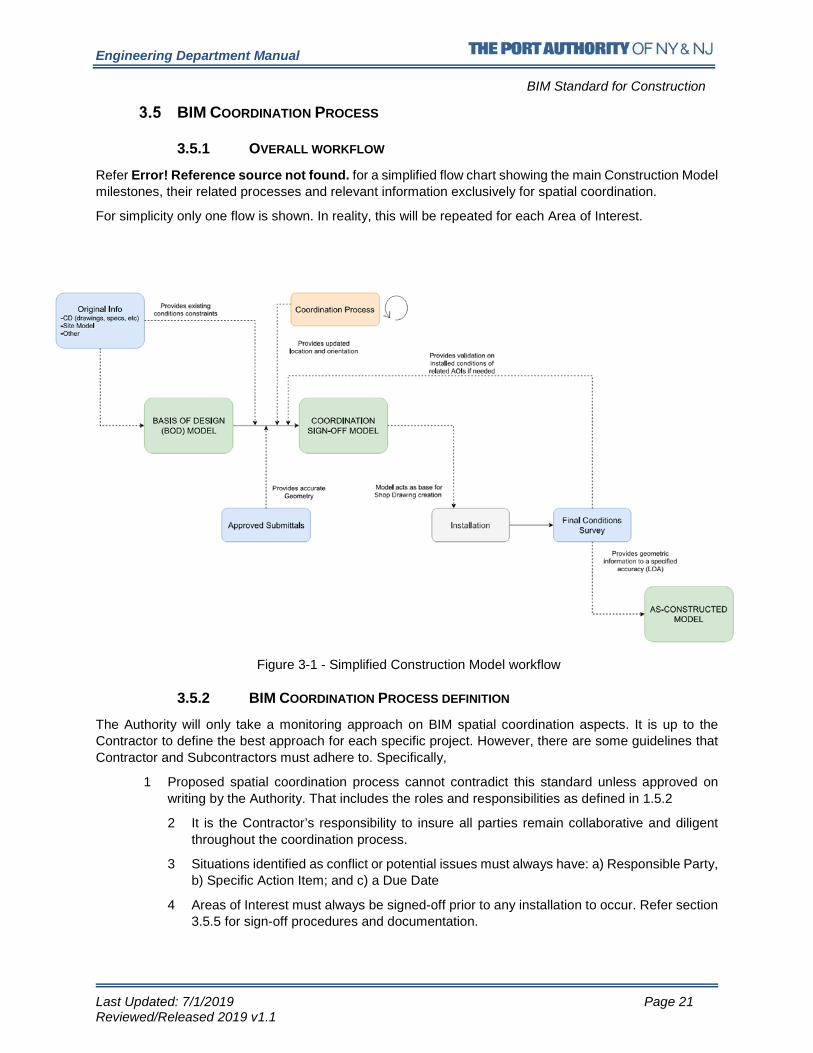
3.5.1 OVERALL WORKFLOW
Refer Error! Reference source not found. for a simplified flow chart showing the main Construction Model milestones, their related processes and relevant information exclusively for spatial coordination.
For simplicity only one flow is shown. In reality, this will be repeated for each Area of Interest.
Figure 3-1 - Simplified Construction Model workflow
3.5.2 BIM COORDINATION PROCESS DEFINITION
The Authority will only take a monitoring approach on BIM spatial coordination aspects. It is up to the Contractor to define the best approach for each specific project. However, there are some guidelines that Contractor and Subcontractors must adhere to. Specifically,
1 Proposed spatial coordination process cannot contradict this standard unless approved on writing by the Authority. That includes the roles and responsibilities as defined in 1.5.2
2 It is the Contractor’s responsibility to insure all parties remain collaborative and diligent throughout the coordination process.
3 Situations identified as conflict or potential issues must always have: a) Responsible Party, b) Specific Action Item; and c) a Due Date
4 Areas of Interest must always be signed-off prior to any installation to occur. Refer section 3.5.5 for sign-off procedures and documentation.

Engineering Department Manual
BIM Standard for Construction
Last Updated: 7/1/2019 Page 22 Reviewed/Released 2019 v1.1
3.5.3 POTENTIAL SCENARIOS AND BASIC WORKFLOWS
Depending on the project specific requirements and the different Subcontractors BIM capabilities and maturity, many different processes may be possible. For practical purposes, this standard defines two main scenarios based on traditional coordination practices, since most of the remaining possibilities can be considered as a combination of the two.
3.5.3.1 SCENARIO A: CONTRACTOR CONCENTRATES ALL MODELING EFFORTS ON A SINGLE PARTY. ERROR! REFERENCE SOURCE NOT FOUND.
In this case, all Construction Model updates are responsibility of the Contractor either directly, or via a third-party consultant (BIM Subcontractor). Subcontractors are still to participate on coordination meetings, and are responsible for validating the model and provide feedback based on their expertise to help ensure that Coordination Sign-off Model is in fact, constructible and efficient. Contractor is to agree on a model validation workflow with each sub (model sharing, joint review, etc.).

Engineering Department Manual
BIM Standard for Construction
Last Updated: 7/1/2019 Page 23 Reviewed/Released 2019 v1.1
Figure 3-2 - BIM Coordination Scenario A

Engineering Department Manual
BIM Standard for Construction
Last Updated: 7/1/2019 Page 24 Reviewed/Released 2019 v1.1
3.5.3.2 SCENARIO B: EACH SUBCONTRACTOR IS IN CHARGE OF EACH TRADE MODEL AUTHORING. ERROR! REFERENCE SOURCE NOT FOUND.
BIM Coordinators act as liaison between Subcontractors and the BIM Lead Coordinator and communicate action items to each Sub’s model authoring team. Individual trade models are shared by means defined and provided by the Contractor, at intervals defined by the BEP, or at the BLC’s request. Subcontractors typically define their internal process for Model validation and trade best practices.
As stated before, decision on adopted coordination process is the sole responsibility of the Contractor.
BEP shall define which of the below is to be followed. Alternatively, it may also define a project specific one if substantially different from (or a combination of) either Scenario A or Scenario B.

Engineering Department Manual
BIM Standard for Construction
Last Updated: 7/1/2019 Page 25 Reviewed/Released 2019 v1.1
Figure 3-3 - BIM Coordination Scenario B

Engineering Department Manual
BIM Standard for Construction
Last Updated: 7/1/2019 Page 26 Reviewed/Released 2019 v1.1
3.5.4 COORDINATION MEETINGS
This Standard uses the concept of Coordination Meeting in the broader sense, not referring only to the spatial coordination aspects, but also to any meeting where Contractor and Subcontractors gather to discuss on model status and agree on specific action items. For example, if one of the Subcontractors’ Model is not meeting the MDS requirements, a meeting between BIM Lead Coordinator and the Sub’s BIM Coordinator to review, discus and agree on corrective actions, is considered a Coordination Meeting.
As stated in 1.5.5.1.4, it is the Contractor’s responsibility to define the appropriate methodology for this type of meetings. Frequency, attendees, typical meeting agenda and action items tracking mechanism, among other topics, must all be recorded in the BEP and submitted to the Authority for review and comment.
There are however, certain requirements that provide a framework for the process to guarantee the outcome is the one desired by the PANYNJ.
Specifically,
• Meetings need to occur frequently enough to ensure Coordination sign-off dates for each AOI, as stated in the BEP, are met.
• At meeting conclusion, every issue addressed must have a specific action item, a responsible party, and a due date. Contractor must track these items, and be able to provide evidence to the Authority, if it so requires it.
• If Subcontractor is not the direct author of the Trade Model (e.g. in Scenario A, refer 3.5.3.1) Contractor must define a Model validation mechanism. For example, by hosting one-to-one (Contractor + Single Sub) or one-to-many (Contractor + All Subs) model joint review sessions. Means and methods for Model validation shall be stated in the BEP.
• The PANYNJ may require to attend these meetings, as an observer only. • Other requirements may be defined in the BIM kick off meeting, for specific projects.
3.5.5 COORDINATION SIGN-OFF
Once a Model achieves this status (for a particular Area of interest), it becomes the single source of truth for spatial coordination. This is relevant because if any conflict arises during construction or installation, the sign-off Model will be the first stop to open a discussion and determine the reasons, and the responsible party, behind the problem.
For this reason, sign-off Model must be the base for all Shop Drawing creation.
3.5.5.1 CONDITIONS FOR SIGN-OFF ELIGIBILITY Essentially, two requirements must be met:
• Geometry has to be according to the LOD stated in the MDS; the reason is that intended location of Model elements may be affected by changes in geometry, connection points of equipment, etc.
• Acceptable interference resolution; a 100% clash-free model, though desired, may not always be possible or practical to pursue. Model may have open items at the time of sign off, under the condition that they all have a responsible party assigned that acknowledges them in the sign-off documentation provided to the Authority. The PANYNJ may still reject the claim for sign-off status if the open items reported are consider of relevance and action items are not satisfactory.
Examples of clashes approvable by the Contractor or Subcontractors:
• Slight insulation clashes (requires trade specialist/Subcontractor to approve) • MEP interference with basic walls, where penetrations are not necessary modeled • Intentional MEP interference with floating ceiling; such as sprinkler, lighting fixtures, etc.
Engineering Department Manual
BIM Standard for Construction
Last Updated: 7/1/2019 Page 27 Reviewed/Released 2019 v1.1
Example of clashes that may require additional approval by the PANYNJ:
• Any interference that is left to be resolved in the field • Interference with access zones or clearances, where this may difficult operation and
maintenance of equipment. • Other as ruled by the Resident Engineer
3.5.5.2 PROCESS AND RECORD
Regardless of the final methodology and process followed for spatial coordination, it is mandatory that all participants (Contractor and Subcontractors) formally sign-off on a coordinated Model prior to any installation.
Refer Annex A for a sign-off template sheet. The actual wording of the document may be rewritten to fit the necessities of each project, on the condition that the language includes the following:
• Statement of conformity regarding coordination status. • Acknowledgement of any outstanding open items (if any), their recommended actions and their
potential implications. These items must be listed, each with their responsible party and expected action.
• Expressed commitment to perform any construction and installation works as close to the signed off Model as possible, and to immediately report any field deviations that may impact future works, specially to other trades.
3.5.6 RECOMMENDED BEST PRACTICES FOR SPATIAL COORDINATION
Spatial Coordination between trades is, as stated before, a process that is mainly defined by the Contractor and its BLC (BIM Lead Coordinator). However, there are some requirements made by the PANYNJ so some basic level of consistency can be reached across projects.
3.5.6.1 FINAL GEOMETRY VS COORDINATION EFFORTS
Ideally, individual model elements’ geometry would first be upgraded to the LOD as required in the MDS, and then fully coordinated between trades. By pursuing a “clash-free” Model without having the final geometry incorporated, there is risk of rework.
On the other hand, if no coordination efforts are done at all before modeled geometry is fully upgraded, there is risk of delays on Coordination sign-off, with subsequent delays on shop drawing creation and even installation/construction activities.
Geometry will likely be upgraded as coordination is on-going. Refer Section 3.9 for some Modeling guidelines that may mitigate the risk of coordinating with geometry that has not yet been fully developed to the target LOD.
The BIM Lead Coordinator will have to define the quantity and quality of interferences that are acceptable for the level of completion that has been reached at any point. This does not mean however, that the PANYNJ will accept any type of interference under the reason of the model not being complete. Clash Report shall demonstrate that reasonable and conscious coordination is being carried out. Refer Section 3.8 for requirements on Clash Report to the Authority.

Engineering Department Manual
BIM Standard for Construction
Last Updated: 7/1/2019 Page 28 Reviewed/Released 2019 v1.1
3.5.6.2 GROUPING CLASHES (WHEN REPORTING TO THE PANYNJ)
Clash/Interference count is an important indicator of a Model’s coordination status, particularly on the final stages of the process (i.e., when close to Sign-off). Naturally, grouping clashes may greatly affect this number.
The BLC shall determine how to group clashes to better reflect the status at any given time. For internal reports (e.g. to Contractor or Subcontractors), this may be done with whatever criteria the BLC sees fit. However, when reporting to the PANYNJ the following shall be considered:
As the first general criteria, coordination should move in a direction that allows for groups to be assigned specific action items from specific parties. This practice may not be entirely possible at the very early stages, but should be always be pursued. “Contractor XXX to submit RFI”, “Subs YYY and ZZZ to work on a solution”, “Sub AAA to move 6” south”; are all examples of specific actions from specific people. Aversely, “All trades to improve coordination in this area” is an example of a poor directive and group assignment.
Grouping criteria may change during the coordination process, but always from larger to smaller areas, and from higher to lower quantity of elements involved. For example: whilst it is acceptable to group all Fire range pipe clashes for an AOI into a single clash while the Model is being populated, it will not be acceptable once the Fire Main has been coordinated with the other trades and is likely on its final position. Following the example, group may contain hundreds of individual clashes at first, but will have to eventually be broken down into smaller groups.
If the same action will solve multiple individual clashes, these may be grouped as a single situation, regardless of the area span of clashes. For example: moving a pipe main and reconnecting branches accordingly, will solve multiple clashes across the entire AOI. These may all be under a single group until said change is made. Then smaller groups will have to be created for the remaining situations.
“False” clashes may be grouped as a single situation, within reason. For example, MEP components that intentionally penetrate basic walls (no shear walls or rated walls).
FEDERATED MODEL SPECIFIC REQUIREMENTS (NWF/NWD) An NWF template will be provided by the PANYNJ’s BIM support group at the BIM Kickoff meeting. This Model will be an empty container with initial setups like starting viewpoints, default search sets, appearance profiler, TimeLiner’s Activity Types and visibility, amongst others.
It is the Contractor’s responsibility to append all trade models to it and develop the template to the project specific NWFs so they remain compliant with this standard.
Project specific NWF settings, folder structure, search sets, etc., shall be stated in the BEP. The process of obtaining an efficient Federated Model setting may imply some trial-and-error, and more so on the earliest stages of a project. The BEP template may contain a specific Annex for this purpose, that can be updated and submitted for Record as needed, without the need to resubmit the entire BEP.
Refer Annex A.1 for BEP template.
The following requirements are mandatory solely for the Federated Models as submitted to the Authority. Contractor and Subcontractors are free to manage internal files as per each Company’s standard or common practice, unless ruled otherwise by the Contractor in the BEP.

Engineering Department Manual
BIM Standard for Construction
Last Updated: 7/1/2019 Page 29 Reviewed/Released 2019 v1.1
This being said, it is recommended that there are as few Federated Models as possible. Ideally, there should be only one per AOI or group of AOIs as defined in the BEP (refer 3.6.1).
Having multiple active NWF files with repeated information may result in miscommunication between stakeholders.
Regardless of the process that the Contractors decides to follow, the only official Models are those submitted to the Authority by the formal channels.
3.6.1 PROJECT BREAKDOWN INTO MULTIPLE FEDERATED MODELS
Depending on the size of the project, it may be convenient to split it into more than one Federated model, each one containing one or multiple Areas of Interest.
To avoid the potential miscommunication explained in 3.6, each AOI may, as a general rule, only be contained in one Federated Model. There could be approved exceptions to this general rule*, but they will be treated on a case-by-case basis.
(*) An exception could be, for example, a Riser federated model that for reference purposes needs to be included in other container files. BIM Lead Coordinator must take all necessary precautions in these cases to prevent any confusion from any of the parties involved.
3.6.2 REFERENCE VIEWPOINTS
The NWF provided by the Authority will have starter viewpoints, that will need to be reoriented and updated once the NWCs are added. This process shall have a consistent outcome throughout all Federated Models created by the Contractor.
Additional requirements as follows:
• Element Color, Hide/Isolate attributes and Sectioning configuration must be saved as a property of the Viewpoint. Regardless of the visibility or scope that it is being used, they should always reset when selecting the Viewpoint.
• For ease of navigation and quick reference, each Federated Models shall have, at minimum: o Viewpoint of the entire project (or AOIs contained in that Federated Model), from a
convenient top-side view o Isometric side and front views
• Viewpoints other than the ones referred to above, shall be saved in an appropriate folder, containing issues of similar nature. Refer 3.6.3 for folder guidelines and requirements.
No claims or justification of work based on other Models than the ones officially submitted to the PANYNJ will be accepted. This is particularly important for work based on shop drawings developed from other models that the ones submitted to the Authority.
As part of the BEP, the Contractor shall provide a table showing which AOIs are contained in which Federated Model.

Engineering Department Manual
BIM Standard for Construction
Last Updated: 7/1/2019 Page 30 Reviewed/Released 2019 v1.1
• Federated models must be purged of redundant or useless viewpoints prior to submission to the PANYNJ.
3.6.3 FOLDER STRUCTURE
Template NWF as provided by the Authority will contain a basic folder structure, for reference on typical viewpoint categories. The BIM Lead Coordinator shall decide on the most appropriate structure for the specific project, and update accordingly.
A basic description of the how viewpoints are categorized and organized shall be included in the BEP.
For consistency, if the project has multiple NWFs, all shall follow the same criteria.
3.6.4 SEARCH SETS
Because of the monitoring activities that the Authority will perform over the modes, as an owner, it is of paramount importance that Sets are created and maintained throughout the lifespan of the Construction Model. This will allow any questioning to the Model to be made in a relatively seamless and consistent fashion.
Search Sets are, for most uses, preferred over Selection Sets. This is due to the ability of the former to remain always current without human action. BLC shall whenever possible, abide by this general rule for locating elements in the model.
NWF Template as provided by the Authority, will contain basic predefined Search Sets in a proposed folder Structure. BIM Lead Coordinator will define the Sets as appropriate for the project, and state them in the corresponding BEP Annex.
3.6.5 APPEARANCE PROFILER
Different uses of the Federated Model may require different visibility settings. For instance, visualization of construction status (Basis of Design, As per Approved Submittal, As-Constructed) implies different grouping and coloring than the one used to identify trades.
For consistency across the project, and to be able to quickly switch from one visualization configuration to the next, Appearance Profilers should work in close tandem with Search Sets (Selection Sets are not recommended).
3.6.5.1 VISUALIZATION CONFIGURATION IN USE BY THE AUTHORITY
The Authority will provide Search Sets (*DAT files) for loading into each Federated Model, at the beginning of the project. These Sets must be refreshed and updated during the initial NWF setup by the BLC, and checked prior to any submission to the Authority to verify they still meet their purpose and are working correctly.
Additionally:
• The color schema of each App. Profiler may be changed only if explicitly requested from the Authority.
• After initial setup, each of the *.DAT files shall be returned to the Authority.
3.6.5.2 VISUALIZATION CONFIGURATIONS USED BY THE CONTRACTOR
The BLC may choose to categorize or represent elements differently than the Authority’s standard coloring, for many number of reasons (e.g., for identifying different Piping systems, or a subdivision in trades like Mechanical dry and wet systems, etc.).

Engineering Department Manual
BIM Standard for Construction
Last Updated: 7/1/2019 Page 31 Reviewed/Released 2019 v1.1
Contractor is welcomed to create and maintain different profilers as deemed appropriate, as long as they are:
• Detailed in the BEP, with sets and coloring schema in use, and intended purpose. • Consistent throughout the different Federated Models submitted to the Authority, if more than
one.

Engineering Department Manual
BIM Standard for Construction
Last Updated: 7/1/2019 Page 32 Reviewed/Released 2019 v1.1
RFI TRACKING The Contractor shall keep viewpoints to visually support any Request for Information to the Authority, whenever possible.
NWF template as provided by the Authority will contain a folder structure similar to the one shown on Error! Reference source not found..
Figure 3-4 - RFI Folder structure
For new RFIs, the BLC shall proceed as follows:
1. Create a new folder with the following naming convention, in the “Open” directory:
*RFI Number*-*Location and Room number if available*-*Brief Description of the issue*
For Example: 061-1st Floor NW Corridor 103-Insufficient overhead space
2. Create one or many Viewpoints, as needed to fully describe the situation.
3. Log Comments using the same viewpoint, to record any novelties regarding this situation. Particularly, when specific action items are assigned and when the issue is closed. Sample comment log as shown on Error! Reference source not found.
Figure 3-5 - Sample RFI Comment log
4. Once RFI is closed, move to the Closed folder.

Engineering Department Manual
BIM Standard for Construction
Last Updated: 7/1/2019 Page 33 Reviewed/Released 2019 v1.1
REPORTING TO THE AUTHORITY It is paramount for a clear and seamless communication with the PANYJ that Contractor submits BIM reports to on time. For the Authority to compare performance of different projects across its portfolio, these reports shall be made following a predefined structure and format.
In other words, template format and content are mandatory unless specific changes are made by the Authority, based on specific project needs.
Table 1-1 contains documents typically submitted as reports to the Authority. It also includes what triggers their submission, and overall description of their contents. Refer Annex A contains templates to assist on their preparation.
MODELING GUIDELINES BEST PRACTICES Certain modeling and Model management practices can help reducing the amount of work (and rework) by BIM Coordinators and other Model Managers. Other benefits on keeping modeling practices consistent include, to name a few:
• Risk mitigation on spatial coordination • Improved Model stability and performance • Easier reporting from models • Information shown on drawings is more reliable • Quantity take-offs and cost analysis result in more accurate results
Annex A contains a compilation of recommended practices for all BIM authors, Coordinators and Managers. Whilst not mandatory, it is highly encouraged that the BLC develops a similar compendium for each project. Ideally, said document should be updated periodically throughout the project incorporating any lessons learned in that period.
It is also recommended that this record is shared with all parties which may profit from it, and can affect the overall stability, reliability and performance of the Models.

Engineering Department Manual
BIM Standard for Construction
Last Updated: 7/1/2019 Page 34 Reviewed/Released 2019 v1.1
4. 4D MODEL
4.1 INTRODUCTION A four-dimensional Model is commonly accepted and referred to in the Industry as the integration between three-dimensional geometry (length-width-depth) and the dimension of time, represented in most cases by the project schedule.
Construction schedule is one of the most important aspects to be considered when coordinating interdisciplinary work as well as phasing where portions of a facility undergoing remodeling must be kept operational, since it defines what work needs to be done, where, when and by whom. If schedule is cost loaded, the potential for analysis is even greater (e.g. facilitates Earned Value analysis or Cash-Flow)
For the PANYNJ as an owner, it allows to monitor one of the most important aspects for construction: that the project will meet its intended completion date. For this specific reason, 4D Model becomes one of the most important BIM deliverables from the Contractor to the Authority.
4.2 PURPOSE OF THIS SECTION There are many scheduling software and methodologies that have the potential to obtain a 4D simulation. The main objective of this standard on this regard, is to provide the minimum requirements the Contractor must meet, as well as to suggest a set of guidelines on a particular methodology that uses software in use by PA Contractor to produce other BIM deliverables.
In this spirit, Contractor may propose an alternative workflow and software on the project’s BEP, as long as it allows for the Authority to benefit from the uses of the 4D Model as defined in 4.3. These alternates shall be subject to approval of the Authority, as part of the BEP original submission. Contractor shall also validate with the PANYNJ the 4D simulation software to use at the BIM Kick-off meeting.
USES AND APPLICATIONS OF THE 4D The PANYNJ will use the Schedule simulation or 4D Model for the following:
• Visualization of Baseline Schedule • Visualization of all Progress Schedule updates • Simulation of each Progress Schedule update versus original Baseline Schedule • Visualization of other site activities, involving elements other than finished or installed work (refer
2.2.4 Site logistics Model Requirements) • Basic cost analysis
TYPICAL 4D SUBMISSION PROCESS To stress the fact that 4D submission is an entirely different aspect and deliverable from traditional Schedule submissions, both simplified processes are presented on Error! Reference source not found..
4D is considered by the PANYNJ as a visualization tool. It is meant to complement, not replace, any of the Schedule obligations the Contractor has with the Authority. In the same sense, BIM requirements made herein are secondary to those made in terms of Scheduling. If there is any contradiction, the latter shall prevail.

Engineering Department Manual
BIM Standard for Construction
Last Updated: 7/1/2019 Page 35 Reviewed/Released 2019 v1.1
Vertical line represents a “contractual” division, separating Contractor from the Owner’s Construction Management Division. The horizontal line is a more conceptual division between traditional construction roles and BIM project roles. Real project roles may defer.
Figure 4-1 - 4D vs. Traditional Schedule submission
4D MODEL REQUIREMENTS
4.5.1 CONSTRUCTION MODEL (NATIVE FILES)
With the purpose of allowing the Authority to quickly determine any element status and activities associated to it, the Contractor is responsible for keeping the following parameters up to date in all native files (trade Models).
• Construction Status: represented by three YES/NO parameters which will indicate in general terms the level of definition for a particular element.

Engineering Department Manual
BIM Standard for Construction
Last Updated: 7/1/2019 Page 36 Reviewed/Released 2019 v1.1
o As per Design Intent: Object or element has been dimensioned based on Contract documentation (Drawings, specifications, etc.), best modeling practices, and meets the LOD and data as specified in the project specific MDS corresponding to the Basis of Design milestone.
o As per Approved Submittal: Element geometry has been upgraded based on Manufacturer content, drawings, cut-sheets, etc., and meets the LOD and data as specified in the project specific MDS corresponding to the Coordination Sign-Off column. See also Submittal No. parameter, defined below.
o As Constructed: Element location and orientation has been field verified and adjusted in the model to a level of accuracy in accordance with the LOA2 column on the MDS. Refer 5.2.3 for clarification on LOA values.
• Submittal No.: this parameter shall incorporate a value equal to the PANYNJ approved submittal number, corresponding to that element. This is critical for the Authority to be able to validate that the element has been accurately defined; this should simplify reporting by the Contractor.
• Activity ID parameter: Every element in the models is to relate to a Construction activity. The value of this parameter, for each element, shall match the unique identifier for the associated activity, as defined by the project’s Work Breakdown Structure (WBS) and stated in the approved baseline schedule.
Modeling practices: in addition to complying with the appropriate LOD for every milestone or stage, it is critical that modeling efforts are carried out considering the 4D simulation application, in particular in regards to model granularity. This is important so components can be properly associated to tasks/activities without creating logic violations or misrepresentations in the construction sequence.
4.5.2 SCHEDULE SETUP
Whilst it is not the purpose of this section to rule on any aspects of the Construction Schedule development, it is worth mentioning that due to the close relation with the 4D Model and simulation, some level of collaboration and coordination will most certainly be necessary between these seemingly separate efforts.
As an example, there is a known limitation that occurs in Navisworks when multiple activities in the Schedule relate to the same geometry. In order to better reflect the construction sequence, some “grouping” of activities may be necessary in the scheduling Software. This however, should not affect the duration, logic, sequence and overall structure of said schedule. Before modifying the schedule in any way, Contractor shall confirm with PANYNJ this will not cause violations or non-compliances in future Schedule submissions.
4.5.3 4D ANIMATION (VIDEO FILE)
With every 4D Model submission, Contractor shall provide a video file showing an animated simulation of the Construction sequence. Video shall be exported from the software used to prepare the simulation, and its minimum requirements are as follow:
Note that for every element there should always be one (and only one) of these parameters with a ticked box (“YES” value). This is to avoid errors when counting elements, which is required for reporting to the Authority and for internal analysis by the BIM Support group.

Engineering Department Manual
BIM Standard for Construction
Last Updated: 7/1/2019 Page 37 Reviewed/Released 2019 v1.1
• When the purpose of the submission is to show Baseline vs Progress schedule comparison, both sequences shall be shown running in parallel in the same video file, either side to side or top to bottom, in such way that they both appear to run in the same timeline.
• The main purpose of the video is to allow for visually appreciation of every element start and end dates, both planned and actual. Contractor shall take every precaution to facilitate this, which may include rotating, sectioning, changing camera position, etc. Temporarily hiding finished elements or making them more transparent for visibility purposes (e.g. finished walls or slabs concealing work in the interior) are acceptable.
• Text wise, animation/s shall display, at minimum: o Dynamic timeline (dates in MM/DD/YYYY format preferable) o Active tasks (progress between 1% and 99%) o Percentages of completion for active tasks o Percentage of completion for project
• Length of the video shall be such that allows for analysis of dates and overall sequence. 60 seconds per year of project is typically an acceptable first approximation.
• Video format/file extension shall be agreed on the BIM kick-off meeting.
4.5.4 4D MODEL
With every 4D/schedule simulation submission, Contractor shall provide a copy of the Model used to create the simulation, on its native format. The 4D file naming convention will be as follows:
PID# - “4D” _ “MM.DD.YYYY” (for example 17012000-4D_09.24.2018)
4.5.5 4D MODEL AND SIMULATION REPORT
A report shall be prepared by the Contractor and submitted for record only, with every 4D Model and simulation. This document shall include basic information on Schedule update and revision, a short narrative of changes since last submission, and any clarification or comments as needed for obtaining a comprehensive submission to the Authority. Refer Annex Error! Reference source not found. for report template.
4D MODEL ASSEMBLY – SUGGESTED WORKFLOW USING NAVISWORKS Since Autodesk Navisworks is the PANYNJ default software for spatial coordination and other BIM related requirements, and considering this platform contains a built-in construction sequence simulator (referred to as TimeLiner), a workflow is presented as a proof of concept.
The process detailed is only of suggestive nature, and the Contractor may propose a different approach. The final methodology for geometry and Schedule integration shall be recorded on the BEP and submitted for approval of the PANYNJ.
A) Construction Models preparation and export
Every trade Model as well as the Site Model needs first to incorporate the Activity ID parameter as described in 4.5.1. Parameter values should be an exact match with the Activity code value representing the task ID.
Every model will also be exported as a single separate *.nwc (Navisworks Cache) file.
Each exported file should comply with the following:

Engineering Department Manual
BIM Standard for Construction
Last Updated: 7/1/2019 Page 38 Reviewed/Released 2019 v1.1
• Only 3D elements are exported • All the parameters are carried over from the native to the cache file. • No linked files should be exported. • NWC file name should follow Revit file naming convention.
B) Federated model assembly
The Navisworks File set needs to be generated using the Navisworks template provided by the Authority. This file will contain the base appearance profiler and basic set ups.
All *.nwc files need to be appended directly from its correct location on the folder structure to maintain a correct path with the *.nwf file. Folder structure should be previously set up in a way that allows for both file types to be easily shared with the Authority.
The *.nwf shall be named with the following convention: PID# - “4D” (sample: 17012000-4D.nwf)
C) Primavera P6 Incorporation
Primavera P6 schedule information can be incorporated in many ways to the federated model. Methodology for using Comma Separated Value file (*.csv) is explained herein:
i. From Primavera P6, export columns containing the following information to an Excel spreadsheet:
o Activity ID o Task name o Task Type o Start Date (Baseline) o End Date (Baseline) o Start Date (Progress Schedule) o End Date (Progress Schedule)
Actual column names may differ depending on personal or corporate scheduling practices from the Contractor.
ii. In Navisworks, set up task types in the TimeLiner Configure tab. Some types are included in the PANYNJ template, but alterations may be in order to match Primavera Task types or project specific needs.
iii. From the Data Source tab, import the *.cvs file obtained from P6 and manually map the Column fields (Navisworks) to External Field Name (*.csv file) as needed.
D) Tasks and geometry link
To enable a 4D Simulation, a link must exist between tasks or Activities on the schedule and the geometric elements on each trade and Site Model. The following steps explain one possible methodology to achieve this:
i. Create a series of Search-Sets that enables the selection of the elements using the incorporated Activity ID parameter value for each element (some commercial and free add-ons allow for automated Search Set creation).
ii. From the Task tab, use the Auto-attach Using Rules feature, creating a custom rule to map the Time-Liner Tasks Name to Search sets with the same name. The Activity ID parameter should act as the nexus between platforms

Engineering Department Manual
BIM Standard for Construction
Last Updated: 7/1/2019 Page 39 Reviewed/Released 2019 v1.1
iii. The Find Items feature in the TimeLiner Tasks tab should be used for checking, amongst other things, that no model element has failed to associate to a task (Unattached/Uncontained items)

Engineering Department Manual
BIM Standard for Construction
Last Updated: 7/1/2019 Page 40 Reviewed/Released 2019 v1.1
5. AS-CONSTRUCTED MODEL
As previously defined in Section 1.5.7, the As-Constructed Model is considered as the final version of the Construction Model, as submitted to the Authority for final approval as part of the project handover.
PURPOSE AND OBJECTIVES As-Constructed model is considered of the utmost importance for the PANYNJ as an owner and operator of its facilities. It is meant to provide reliable and accurate information of the finished Work.
5.1.1 INTENDED USES BY THE PANYNJ
As-Constructed Model will be used for:
Provide basic asset information for the Authority to export to the FM software in use. As design input for future expansions and/or renovations made to the facility.
5.1.2 POTENTIAL USES BY THE CONTRACTOR
The Authority encourages the use of Point Cloud and Laser Scan technologies even if not required by Contract. Contractor may use this for the following:
Adjust the Construction model geometry to the surveyed information. Keep record of Construction progress and Site conditions.
BASIC DEFINITIONS AND CLASSIFICATIONS
5.2.1 REAL WORLD CONDITIONS
This manual considers two types of actual or “real-world” conditions:
• Existing conditions: they are considered as the aggregate of any and all material objects or element that Contractor must work with and around of, in order to execute the Work. Existing conditions may or may not remain at the end of the project (e.g. due to Demolition or decommissioning activities). Requirements for modeling of existing conditions are defined in the Project Model Development Spec.
• As-Constructed conditions: final condition of all completed Work. Unless specified differently in the Contract, this refers to final Work only (no temporary). Requirements for the As-Constructed Model(s) are defined in the Project Model Development Spec.
5.2.2 DATA TYPES: THE AUTHORITY RECOGNIZES TWO BASIC TYPES OF INFORMATION:
• Geometrical information: related to size, shape, quantity, location and orientation of elements.
• Asset information: specific data on elements of interest, typically but not limited to equipment information such as Manufacturer, model, make, etc. Additionally, Asset Information can be Tier 1 or Tier 2 data, where:
o Tier 1: Refers to all information that can be acquired without the element to be actually installed. Example: Manufacturer, Model, Make, Serial Number, etc.

Engineering Department Manual
BIM Standard for Construction
Last Updated: 7/1/2019 Page 41 Reviewed/Released 2019 v1.1
o Tier 2: Refers to information that does not fall on Tier 1. Example: Installation date, testing results (if requested), etc.
5.2.3 LEVEL OF ACCURACY (LOA)
The PANYNJ adopts the LOA specifications as stated in the latest U.S. Institute of Building Documentation (USIBD) LOA Specification, as publicly available on https://usibd.org.
Extending on this specification, this manual further defines the following two different types of LOAs:
• LOA1: referring to how accurately an element’s geometric information has been captured
• LOA2: referring to how accurately an element’s geometric features has been represented in the model.
LOA values, where applicable, are recorded in the MDS for each Uniformat line item. LOA values shall only refer to intended dimensions, unless specified otherwise.
5.2.4 TERRESTRIAL LASER SCAN (TLS)
TLS, sometimes referred to as LiDAR (Light Detection and Raging), is a surveying method that measures distance to a target by illuminating the target with pulsed laser light, and measuring the reflected pulses with a sensor. Differences in laser return times and wavelengths can then be used to make digital 3D representations of the target, commonly referred to in the industry as Point Clouds.
5.2.5 REQUIREMENTS
As part of the contractual requirements, Contractors must typically provide record of final installed/constructed conditions to the PANYNJ. Additionally, depending on the project there may be a requirement to capture and record Existing Conditions as well, as part of the Work. Contractor may also choose to capture and record any temporary work.
Regardless of the case, Contractor will typically work in the following sequence:
Planning Data Capture Data validation (Assurance) Data delivery and handover
As-Constructed Model requirements have been broken down into this steps or sequence.
Both the elements that are to incorporate asset information as well as the actual parameters that are to contain this data in the models, are defined in the project specific Model Development Specification (MDS).
Both the elements that are to incorporate asset information as well as the actual parameters that are to contain this data in the models, are defined in the project specific Model Development Specification (MDS).

Engineering Department Manual
BIM Standard for Construction
Last Updated: 7/1/2019 Page 42 Reviewed/Released 2019 v1.1
5.2.5.1 PLANNING REQUIREMENTS
• Related to geometrical information: Contractor shall deliver to the Authority an Existing and As-Constructed Conditions Survey Plan. This document will cover the following items, at minimum:
i. Detailed plan of subdivision of survey Areas and identification of all elements to be surveyed at any given stage.
ii. Detailed list of position and coordinates of Control Point and control lines to be used as reference on the survey Process.
iii. Detailed Schedule on survey activities and correlation with Construction schedule. Schedule must include dates on which Point Clouds (or approved equivalent) will be submitted to the Authority.
iv. Proposed equipment to execute this work, considering it needs to comply with LOA1 project requirements.
v. Description of the process that will be utilized to incorporate surveyed information to the model, as well as the control methods that will be implemented to guarantee final model complies with the project LOA2 requirements.
This plan shall be submitted to the Authority for review and comment, and once approved, it shall be incorporated as an Annex to the BEP.
• Related to Asset Information: Contractor shall include as part of the BEP, the following information at minimum;
i. A copy of the list of elements that will incorporate all asset information as requested by the PANYNJ for that specific project. If no list is provided, the Contractor shall propose one, based on the project specific MDS requirements.
ii. Approximate dates where Tier 1 and Tier 2 information will be incorporated to the models.
iii. Overall description of the process that will be utilized to incorporate information to the models, especially in relation to the geometric data.
5.2.5.2 DATA CAPTURE REQUIREMENTS
• Geometric information: There are many methodologies to measure shape and position of a constructed or existing element: tape measure, laser measure, long tape, measuring wheel, etc. Naturally, the LOA1 that can be guaranteed from each can greatly vary.
Considering the Authority’s requirements for LOA1 values, it is likely that the only methodologies that can meet them are the ones using some form of Laser Scanner (LiDAR) survey, often in combination with Total Station (TST) survey. For this reason, this Standard refers to these types of equipment and known associated processes (Point cloud generation, incorporation to models, etc.).
Only when LiDAR is not specifically required by contract, the Contractor may propose alternate ways of obtaining the required accuracy. Contractor shall in this case, submit the proposed equipment and methodology as part of the Existing and As-Constructed Conditions Survey Plan, and include proof that LOA1 requirements can be met. Evidence may consist on

Engineering Department Manual
BIM Standard for Construction
Last Updated: 7/1/2019 Page 43 Reviewed/Released 2019 v1.1
Manufacturer information, calibration certificates, white papers from or endorsed by a recognized entity, etc.
• Asset information: elements of special interest by the Authority have been identified in the specific “Asset” column on the MDS, for the As-Constructed Model. MDS also defines all applicable attributes/parameters for each Uniformat level. Each of these attributes are included as parameter in the PANYNJ’s standard Shared Parameter files, under parameter group “Asset Management”.
Contractor shall use these fields for data entry in the BIMs, regardless of other forms of delivery of this information (e.g., Shop drawings, Manufacturer cut-sheets, O&M Manuals, etc.) required elsewhere in the Contract.
5.2.5.3 DATA VALIDATION (ASSURANCE)
• Geometric information: Contractor must use the available As-Constructed shared parameter (YES/NO parameter type, refer 4.5.1) to identify any element that has been adjusted as per field verified information or Survey. The PANYNJ will verify the accuracy to which said elements have been represented (LOA2) by comparing them to the survey data provided by the Contractor. Depending on the survey method used, Contractor may provide one of the following:
a) If a TST is used: o Table showing the following information, for every surveyed point:
• Point identification number. • X, Y, Z coordinates. • Identification Comment.
o Plan Drawing showing schematic position of the surveyed points, for ease of identification.
b) If a LiDAR equipment is used: o Unified RCS Point Cloud file with shared coordinates system o A table similar to the one described for TST survey, but for control Points used to
reference the Point Cloud to the project coordinate system.
• Asset information: It shall be incorporated to the Construction Model as it becomes available, and will be reviewed by the Authority throughout the duration of the project. Contractor must use the available AM Tier 1 and AM Tier 2 shared parameters (both YES/NO parameter types) to identify any and all elements that have incorporated the respective Tier information. This will help the both the Contractor and the Authority to quickly filter and locate elements for checking the associated data.
The Contractor shall also regularly submit a list of all elements including Tier 1 and 2 information, highlighting any new entries since last submission. This list will be due with every submission of the Construction Model to the Authority, unless specifically requested otherwise.
5.2.5.4 DATA DELIVERY
Refer Error! Reference source not found. for format and typical frequency of deliverables related to As-Constructed conditions and Asset information, as well as a high level summary of the requirements made on this section. Frequency needs to be validated in the BEP on a project-by-project basis.

Engineering Department Manual
BIM Standard for Construction
Last Updated: 7/1/2019 Page 44 Reviewed/Released 2019 v1.1
Table 5-1
Deliverable Frequency Special requirements
Point Cloud
(Partial)
Two weeks at the latest, after every survey
• To be delivered in a portable format (e.g. Flash drive). • Unified format (RCS) mandatory. • Must consistently incorporate Area identifier and survey
date in the RCS file name. • Same shared coordinates as the Construction Model. • Must provide separate record of Survey Points used to
align Point Cloud to project coordinates.
Point Cloud
(Full extent of project)
Only once, as part of the final As-Constructed Model submission.
Same as partial Point Clouds, plus:
• Include only the latest survey for every area, if more than one.
Survey Points (for survey using TST)
Two weeks at the latest, after every survey
• Point identification number. • X, Y, Z coordinates. • Identification Comment.
Tier 1 and Tier 2 information
With every Construction Model submission
• Information must be included as soon as it becomes available.
• Information must be embedded in the trade models • Contractor must use shared parameter created by the
Authority.
As-Constructed Model progress report
With every Construction Model submission, as part of the Model Report.
Aggregate list of all elements that have been surveyed and adjusted to final conditions. New elements since previous submission need to be highlighted.
Aggregate list of all elements that have incorporated Tier 1 and/or Tier 2 information. New elements since previous submission need to be highlighted.
Both lists must match reports (Revit Schedules) exported from the Models, using the tracking parameters mentioned in this section (As-Constructed, AM Tier 1, AM Tier 2)
5.2.6 FINAL SUBMISSION AND APPROVAL
5.2.6.1 AS-CONSTRUCTED MODEL SUBMISSION
This Model is only submitted as such once ALL the following conditions have been met:
• Project Engineer has confirmed that construction has achieved substantial completion • All required Asset information has been incorporated to the trade models by the Contractor (or
Subcontractors)

Engineering Department Manual
BIM Standard for Construction
Last Updated: 7/1/2019 Page 45 Reviewed/Released 2019 v1.1
• As-Constructed conditions have been replicated in a way that LOA2 requirements are satisfied. • Target LODs as stated in the MDS have been achieved • All outstanding issues regarding BIM as recorded on the BIM Submission log have been closed.
Previous submissions of the Construction Model containing partial information or complying only partially with the above list, do not count as submission of the As-Constructed Model.
Contractor shall submit for approval all native files (e.g. Revit, Civil 3D if applicable) as well as a Navisworks NWD* federated file.
*Note: NWD file shall be a data-rich model. Prevision must be taken by the BIM Lead Coordinator to ensure that individual files composing the NWD are exported from the native platforms in a way that all possible parameters and their values are carried over to Navisworks.
5.2.6.2 APPROVAL PROCESS
The Authority’s BIM Support Group and Asset Management team will thoroughly review the Models for compliance with this Standard. The Authority may reject the deliverables if not satisfactory, in which case the Contractor shall meet with the PANYNJ to review non-compliances, then revise and resubmit the Models for approval, on an agreed time period (typically between two and four weeks depending on the amount and severity of the issues.
Cycle will continue and Project closure may not occur until BIMs are approved. Periodical Model and data validation throughout Construction, as required in this Standard, should minimize the possibility of such scenario.

Engineering Department Manual
BIM Standard for Construction
Last Updated: 7/1/2019 Page 46 Reviewed/Released 2019 v1.1
ANNEX A
A.1. BIM EXECUTION PLAN (TEMPLATE)

BIM EXECUTION PLAN TEMPLATE [Instructions for completing the BEP as well as editable fields in it are shown in red print. Review, replace and/or remove all text in red with current project information before completion of final BEP]
[PROJECT NAME]
BIM Execution Plan (Stage IV)
[Version 1.0 Month Day, YYYY]
GENERAL CONTRACTOR: [NAME OF THE CONTRACTOR]
CONTRACT No.: XXX-000.000

BIM Execution Plan
PROJECT NAME (SAME AS COVER PAGE)
TABLE OF CONTENTS
TABLE OF CONTENTS .................................................................................. 48
1. INTRODUCTION .................................................................................... 50 1.1 PURPOSE ............................................................................................................................. 50 1.2 SCOPE ................................................................................................................................. 50
2. SECTION I: PROJECT INFORMATION .................................................... 50 2.1 FACILITY .............................................................................................................................. 51 2.2 CONTRACT NUMBER ............................................................................................................. 51 2.3 PROJECT NAME .................................................................................................................... 51 2.4 PROJECT IDENTIFICATION NUMBER........................................................................................ 51 2.5 PROJECT LOCATION ............................................................................................................. 51 2.6 PROJECT ADDRESS .............................................................................................................. 51 2.7 PROJECT TYPE ..................................................................................................................... 51 2.8 PROJECT DESCRIPTION ......................................................................................................... 51 2.9 PROJECT OWNER ................................................................................................................. 51 2.10 PROJECT SCHEDULE............................................................................................................. 52 2.11 PROJECT CONTACTS ............................................................................................................ 53
2.11.1 CONSTRUCTION MANAGEMENT & PROJECT CONTROL .............................................. 53 2.11.2 THE PORT AUTHORITY OF NEW YORK AND NEW JERSEY .......................................... 53
3. SECTION II: PROCESSES AND SCHEDULES ........................................... 54 3.1 OVERALL APPROACH ............................................................................................................ 54 3.2 CONSTRUCTION MODEL DEVELOPMENT ................................................................................. 54
3.2.1 SITE MODEL ........................................................................................................... 54 3.2.2 CONSTRUCTION MODEL BREAKDOWN ..................................................................... 54 3.2.3 AREAS OF INTEREST (AOI) ..................................................................................... 55 3.2.4 LEVEL OF DEVELOPMENT (LOD) AND PARAMETRIC INFORMATION ............................. 55 3.2.5 CONSTRUCTION MODEL MILESTONES AND SCHEDULE .............................................. 55 3.2.6 SPATIAL COORDINATION ......................................................................................... 56 3.2.7 MODEL VALIDATION ................................................................................................ 56 3.2.8 SHOP DRAWING DEVELOPMENT AND FIELD WORK ..................................................... 56
3.3 4D MODEL AND SIMULATION DEVELOPMENT ........................................................................... 56 3.4 AS-CONSTRUCTED CONDITIONS AND ASSET INFORMATION ...................................................... 56

BIM Execution Plan
PROJECT NAME (SAME AS COVER PAGE)
3.5 COMMUNICATION REQUIREMENTS .......................................................................................... 57 3.5.1 PROJECT BIM KICK-OFF MEETING .......................... ERROR! BOOKMARK NOT DEFINED. 3.5.2 COORDINATION MEETINGS ...................................................................................... 57 3.5.3 INFORMATION EXCHANGE ....................................................................................... 57 3.5.4 COMMUNICATION .................................................... ERROR! BOOKMARK NOT DEFINED. 3.5.5 CONSTRUCTION MODEL COORDINATION .................. ERROR! BOOKMARK NOT DEFINED.
3.6 MODEL STRUCTURE .............................................................. ERROR! BOOKMARK NOT DEFINED. 3.6.1 MODELS BREAKDOWN ............................................ ERROR! BOOKMARK NOT DEFINED.
4. SECTION III: PROJECT SPECIFIC BIM REQUIREMENTS .......................... 60
4.1 ADDITIONAL SHARED PARAMETER LIST ................................................................................. 60 4.2 DEVIATIONS FROM BIM SPECS .............................................. ERROR! BOOKMARK NOT DEFINED. 4.3 APPENDIX A: LOD MATRIX AND SCHEDULE ....................................................................... 60 4.4 APPENDIX D: ..................................................................................................................... 60

BIM Execution Plan
PROJECT NAME (SAME AS COVER PAGE)
1. INTRODUCTION
1.1 PURPOSE
The objective of the BIM Execution Plan (BEP) is to define a framework for collaboration among the PANYNJ‘s BIM Support Group, General Contractor, Construction Management Division (CMD), design team and Subcontractors, in order to guarantee
This BIM Execution Plan will: • Define and facilitate the exchange of information between all participants. • Establish coordination procedures among all trades. • Organize all BIM related activities around a philosophy of collaboration.
The purpose is to ensure all BIM related information provided by all participants during the execution of the project is consistent and useful throughout Construction Stage.
1.2 SCOPE
This BEP reflects and records all refinements made to the PANYNJ BIM standard, specifically for the afore mentioned project.
Any aspect not addressed explicitly on this document is ruled by the PANYNJ BIM Standard Manual. (remove statement above if project is part of a program with specific BIM requirements) Any aspect not addressed explicitly on this document is ruled by the Program BIM requirements. If not addressed by the program, then that aspect is ruled by the PANYNJ BIM Standard (remove statement above if project is NOT part of a program, or if there are no program-specific requirements)

BIM Execution Plan
PROJECT NAME (SAME AS COVER PAGE)
2. SECTION I: PROJECT INFORMATION
2.1 FACILITY
Enter facility name here
2.2 CONTRACT NUMBER
Enter Contract number here
2.3 PROJECT NAME
Enter project name here
2.4 PROJECT IDENTIFICATION NUMBER
Enter the PID Number
2.5 PROJECT LOCATION
Describe the location of the project
2.6 PROJECT ADDRESS
Enter the project address
2.7 PROJECT TYPE
Indicate what type of building/structure is being constructed
2.8 PROJECT DESCRIPTION
Provide a brief narrative covering project scope, estimated completion date, and project area (SF), and other general information as seen fit.
2.9 PROJECT OWNER
List The Port Authority of New York & New Jersey Line Department for which the project is being developed

BIM Execution Plan
PROJECT NAME (SAME AS COVER PAGE)
2.10 PROJECT SCHEDULE
PHASE MILESTONE DESCRIPTION START DATE
FINISH DATE
NUMBER OF WEEKS
Stage IV
Management & Construction
DD-Mon-YY DD-Mon-YY
DD-Mon-YY DD-Mon-YY
DD-Mon-YY DD-Mon-YY
DD-Mon-YY DD-Mon-YY
DD-Mon-YY DD-Mon-YY
DD-Mon-YY DD-Mon-YY
DD-Mon-YY DD-Mon-YY
DD-Mon-YY DD-Mon-YY
DD-Mon-YY DD-Mon-YY
DD-Mon-YY DD-Mon-YY
NOTE Define project-specific milestones, including % of completion where applicable. These are actual Construction milestones and are to be in line with the Baseline Schedule as approved by the PANYNJ. Milestone descriptions may or may not coincide with BIM submission milestones as defined in 2.12.5b of this template.

BIM Execution Plan
PROJECT NAME (SAME AS COVER PAGE)
2.11 PROJECT CONTACTS
Roles as described in this section have all responsibilities and obligations as defined in the PANYNJ BIM Standard for Construction. Every person on list 2.11.1 is considered a BIM user.
Complete list below with Name and contact information for the Contractor's designated BIM Lead Coordinator, and each of his subcontractor's designated BIM Coordinators (if any). Roles in red below are to be used as an example.
2.11.1 CONSTRUCTION MANAGEMENT & PROJECT CONTROL
ROLE COMPANY NAME EMAIL PHONE BIM Author
(Y/N) Project Manager CONTRACTOR N
BIM Lead Coordinator
CONTRACTOR Y
Document Controller
CONTRACTOR N
Scheduler CONTRACTOR N
Surveyor CONTRACTOR N
BIM Coordinator 1 SUBCONTRACTOR 1
(specify Trade) Y
BIM Coordinator 2 SUBCONTRACTOR 2
(specify Trade) Y
BIM Coordinator n SUBCONTRACTOR n
(specify Trade) Y
2.11.2 THE PORT AUTHORITY OF NEW YORK AND NEW JERSEY
ROLE DEPARTMENT DIVISION NAME EMAIL PHONE Resident Engineer
PATH/PABT/JKF/etc. Construction Management
Assistant RE PATH/PABT/JKF/etc. Construction Management
BIM Coordinator (PA)
Engineering Solutions Eng. Operations
Scheduler (PA) Project Controls Eng. Operations
Lead Architect Engineer
Electrical/Mechanical/etc.
EAD

BIM Execution Plan
PROJECT NAME (SAME AS COVER PAGE)
3. SECTION II: PROCESSES AND SCHEDULES
3.1 OVERALL APPROACH
Develop this section to define, explain and graphically represent the project’s specific processes that support the general workflow as outlined in Section 3.5.1 in the PANYNJ’s BIM Standard for Construction.
You may also provide a brief narrative on intended approach for Site Model and 4D Model development.
3.2 CONSTRUCTION MODEL DEVELOPMENT
3.2.1 SITE MODEL
a. PROJECT COORDINATES
All models involved in this project shall inherit the same coordinates as the Site Model, as provided by the PANYNJ’s BIM Support Group. This universal coordinate system and its origin shall remain the same throughout the project, unless directed otherwise by the Authority.
Contractor or Subcontractors may require to stablish different “local” coordinates. Whilst relocating the project itself is not acceptable, it is possible to propose a new set of coordinates that relates to the one defined by the Authority (the original coordinates must be kept, as well). If Contractor chooses to do so, transformation (between the two origins) on X,Y,Z and rotation shall be stated in this section, as well as the reason and need for such change. Note the PANYNJ reserves the right to reject such change, or even request to move back to the original coordinates if this causes any issues, at the sole discretion of the PANYNJ.
b. SITE MODEL DEVELOPMENT, UPDATE AND INTEGRATION
Requirements for the Site Model are ruled by Section 2.0 of the PANYNJ’s BIM Standard for Construction. Further develop this section to briefly describe the uses the Contractor will make of the Site Model, update frequency and other aspects considered relevant.
3.2.2 CONSTRUCTION MODEL BREAKDOWN
The construction Model, will be composed by the following individual and complementary models.
Trade Model Name Responsible Authoring Party Architectural APA000000-3D_CENTRAL.rvt General Contractor
Mechanical HVAC
MPA000000-HVAC_CENTRAL.rvt Subcontractor 1
Electrical EPA000000-TR_CENTRAL.rvt Subcontractor 2

BIM Execution Plan
PROJECT NAME (SAME AS COVER PAGE)
For naming conventions refer to PANYNJ BIM Manual, 1.18.8 in the General Section. For construction Projects, the contract number (in use by the Authority) will replace the PID number, removing any non-alphanumerical characters. Fictional project with Contract number “PA-000.000” was used un the samples above.
3.2.3 AREAS OF INTEREST (AOI)
AOIs are defined in Section 3.4.2 of the PANYNJ’s BIM Standard for Construction. For spatial coordination, as well as scheduling other Construction Model milestones, the current project will be broken down as follows:
AOI code Description Location UG01 All utilities running underground, within the Building
perimeter and up to 5’ from it Underground (Building)
SU01 All Site utilities, below and above ground Site
GLM1 All trades on Mechanical Room 01 Between gridlines C&1 and F&4
GL01 All trades on Ground Level zone 01 Between A&1 and M&12, not including Mech Room 01
RL01 All trades on Roof Level zone 01 Roof
Table filled in as reference only. Refer Construction Manual Section 3.4.2.1 for guidelines on how to define them.
3.2.4 LEVEL OF DEVELOPMENT (LOD) AND PARAMETRIC INFORMATION
All Building Information Models that are part of the project shall meet the LOD requirements made in the Project’s Model Development Specification (MDS), included on Annex XX to this BEP.
Definitions regarding Current and Target LOD, and their relation to the AOIs shall be as defined in the PANYNJ BIM Construction Standard.
In addition to the development of the Geometry to each required level, elements in the Models shall also incorporate data as and when requested by the project MDS (refer auxiliary tabs within it).
3.2.5 CONSTRUCTION MODEL MILESTONES AND SCHEDULE
Level of Development (LOD) as stated in the Project Model Development Specification (MDS) will be achieved in the following dates, for each Area of interest:

BIM Execution Plan
PROJECT NAME (SAME AS COVER PAGE)
AOI code BOD Coordination Sign-off
AOI001 MM/DD/YYYY MM/DD/YYYY
AOI002 MM/DD/YYYY MM/DD/YYYY
AOI003 MM/DD/YYYY MM/DD/YYYY
AOI004 MM/DD/YYYY MM/DD/YYYY
3.2.6 SPATIAL COORDINATION
Define the framework for BIM 3D spatial coordination to be implemented in this project. Reference Section 3.5 in the BIM Construction Standard. Model Authors responsible for addressing coordination issues need to be clearly identified. Define also how interferences will be reported and communicated for resolution. Graphically represent the process to be followed, if different to Scenarios A or B depicted in Section 3.5.3 in the BIM Standard for Construction.
When the conditions described in Section 3.5.5 of the BIM for Construction Standards are met, documentation for Coordination Sign-Off will be released. Refer Annex XX for Sign-off form.
3.2.7 MODEL VALIDATION
Define the process by which Trade Models will be reviewed and validated by the respective trade experts or representatives, in case they are not Model Authors themselves. For example, if there is a BIM Subcontractor tasked with the modeling of the mechanical components but are not the Mechanical contractor themselves, these two parties shall meet to review the accuracy and constructability of the Model at periodic intervals, and prior to sign-off.
3.2.8 SHOP DRAWING DEVELOPMENT AND FIELD WORK
Define how Shop Drawings will relate to the model, to insure they accurately represent the Coordination Sign-off status, in case they are not developed from the models used for spatial coordination.
3.3 4D MODEL AND SIMULATION DEVELOPMENT
Model requirements are as outlined in Section 4.5 in the PANYNJ’s BIM Standard for Construction.
Define processes regarding 4D Model development. Including but not necessarily limited to: Software used, color scheme proposed to represent late tasks and other as needed, flowchart depicting the information flow and responsible parties, validation procedures, etc.
3.4 AS-CONSTRUCTED CONDITIONS AND ASSET INFORMATION
Areas of Interest (AOI) are defined in section 3.4.2 of the BIM Standards for Construction.
AOI code Date Captured
Date Represented
Tier 1 Info Incorporated
Tier 2 Info Incorporated
AOI001 MM/DD/YYYY MM/DD/YYYY MM/DD/YYYY MM/DD/YYYY

BIM Execution Plan
PROJECT NAME (SAME AS COVER PAGE)
AOI002 MM/DD/YYYY MM/DD/YYYY MM/DD/YYYY MM/DD/YYYY
AOI003 MM/DD/YYYY MM/DD/YYYY MM/DD/YYYY MM/DD/YYYY
AOI004 MM/DD/YYYY MM/DD/YYYY MM/DD/YYYY MM/DD/YYYY
Note: “Date Captured” refers to Laser Scan survey schedule, when this is the methodology chosen for capturing final conditions. Survey is considered a Construction activity and thus should be accounted for in the project’s construction schedule. Dates reported here shall match those in the Construction schedule.
3.5 COMMUNICATION REQUIREMENTS
3.5.1 MEETINGS
Overall intent, tentative agenda and attendees for BIM progress Meetings and BIM submission review Meetings are defined in the BIM Standard for Construction, Sections 1.5.5.1.2 and 1.5.5.1.3, respectively.
BIM coordination meetings, as defined in Section 1.5.5.1.4, will be treated as follows:
Develop this paragraph to state the approach to this type of meetings. State frequency and attendee list, as well as typical input and expected outcome from each meeting.
Additionally, this project will have the following scheduled meetings, not contemplated in the PANYNJ Standards (Include any meeting considered relevant, for example Model review sessions with Contractor’s scheduler or field personnel. Delete paragraph if not applicable):
a) Meeting Name a. Meeting Goal b. Meeting Tentative agenda c. Meeting Attendees
Summarized meeting schedule as follows:
MEETING NAME FREQUENCY
BIM Progress Meeting Once a month, one week prior to monthly BIM submission to the PANYNJ
BIM Submission Review Meeting Between 7 to 14 calendar days from monthly BIM submission to the PANYNJ
BIM Coordination Meeting Define
Other Define, if applicable
3.5.2 INFORMATION EXCHANGE
Information exchange between the Port Authority and the General Contractor (name) shall take place via Livelink (or other approved system).

BIM Execution Plan
PROJECT NAME (SAME AS COVER PAGE)
Additionally, Contractor’s Name will proceed as follows, for exchanging information with Subcontractors and others as needed: Develop this section to briefly state information exchange protocols. Consider the PANYNJ’s security protocols for managing Confidential and Confidential Privileged (C & CP) information, where applicable.
a. INFORMATION EXCHANGE SCHEDULE
DESCRIPTION ORGANIZATION DATE
(first revision only) FREQUENCY EXCHANGE
FORMAT
BIM Execution Plan
Schedule
Schedule
Updates
Construction Model
4D Model
Model Report
Clash Reports
Schedule Animations
Scan Data
As Constructed Model
b. AS-CONSTRUCTED VERIFICATION PROCEDURES
See Section 1.10 As-Constructed Model in The Port Authority of NY & NJ E/A Construction Division BIM Standard (Provide development procedures for As Constructed Models. Specify how information will be registered and submitted by the General Contractor, how often the data will be processed – in a .csv file -, how the procedure with the BIM subcontractor will be done if applies, etc. Also provide the Model Management process to reflect the phase from the As-Built conditions to As- Constructed)

BIM Execution Plan
PROJECT NAME (SAME AS COVER PAGE)
Proposed methodology for collecting and including information required by the Authority for inclusion of the As-Constructed model in its asset management system, as defined elsewhere in this clause.
a. FIELD SURVEY
See Section 1.10 As-Constructed Model in The Port Authority of NY & NJ E/A Construction Division BIM Standard (Provide Flow diagrams demonstrating how the Construction Model will be used at the construction site, including process and frequency for capturing as-constructed conditions with land survey equipment)
Field Survey Plan and Schedule Provide a schedule of scanning
b. LASER SCANNING
See Section 1.10 As-Constructed Model in The Port Authority of NY & NJ E/A Construction Division BIM Standard
(Provide Flow diagrams demonstrating how the Construction Model will be used at the construction site, including process and frequency for capturing as-constructed conditions with laser scans)

BIM Execution Plan
PROJECT NAME (SAME AS COVER PAGE)
4. SECTION III: PROJECT SPECIFIC BIM REQUIREMENTS
4.1 ADDITIONAL SHARED PARAMETER LIST
4.2 BEP APPENDIX A: LOD MATRIX AND SCHEDULE
(Specify the proposed process and workflow showing how schedule information will be integrated to all the model phases, until final deliverables- Refer to the MDS for detailed information)
4.3 BEP APPENDIX B: DEVIATIONS APPROVED BY THE PANYNJ
(Specify any other specific process and or map to explain any deviation from the General Standards, once approved by the PANYNJ)
4.4 BEP APPENDIX C: COORDINATION SIGN-OFF FORM

Engineering Department Manual
BIM Standard for Construction
Last Updated: 7/1/2019 Page 61 Reviewed/Released 2019 v1.1
A.2. PROGRESS REPORT (TEMPLATE)

BIM Submission Report
Project: Project Name PID: 00000000 Contract Number: AAA-000.000
BLC (Contractor): BIM Lead Coordinator Name PANYNJ BIM Coordinator: Name Date of Submission: 00/00/0000
Submission for: Month, YYYY
1.0 Submission Summary Construction Model Updates Completeness Spatial coordination PACCs/RFIs Other 4D Model and Simulations Baseline Simulation Updated Progress Schedule Other As-Constructed Information Captured conditions Asset Information Other
Mark with an X, depending on the contents of the submission.

2.0 Construction Model 2.1 Models included in current submission:
Model 1 Name Model 2 Name Model 3 Name Model 4 Name Model … Name Model n Name 2.2 Models with changes since previous submission:
Model 1 Name Model 2 Name Model 3 Name Model … Name Model n Name 2.3 Historical Model compliance review status (past 6 months):
Model Name Month A Month B Month D Month E Month F Month G Model 1 Name APP APP APP APP APP APP Model 1 Name NA NA NA NA NA NA Model 1 Name FRO FRO FRO FRO FRO FRO Model 1 Name APP APP APP APP APP APP Model … Name NA NA NA NA NA NA Model n Name FRO FRO FRO FRO FRO FRO
Status may be: APP (approved/passed), NA (not approved/failed), or FRO (for record only). This is based on past submissions responses by the PA’s BIM support group
2.4 Narrative of changes on construction Models since previous submission:
Describe Updates and work Done on Models since last Submission. This section should elaborate on what’s checked on item 1.0 Submission Summary, under Construction Model Updates; and consider the updates on tables on 2.5, 2.6, 2.7.

2.5 Element count per Construction Milestone:
Elements Count Model Name Total count Basis of Design Coordination Sign-off As-Constructed Model 1 Name
Elements Number Elements Number Elements Number 00% 00% 00%
Model 2 Name
Elements Number Elements Number Elements Number 00% 00% 00%
Model 3 Name
Elements Number Elements Number Elements Number 00% 00% 00%
Use Revit scheduling tool to obtain overall quantities. Total count should not be obtained by the same method, since it’s a Control figure (sum of three different statuses should be within a 5% deviation of the total count). Refer section 4.51 of the Construction Standard.
2.6 List of Approved Submittals incorporated to Construction Model:
Submittal Revision Description Approved
by PA Model Updated (Family Name)
Update Date
Submittal # Revision # Description of Submittal MM/DD/YY Model 1 Name (Family 1 Name)
MM/DD/YY
List content in the Revit Models that has been updated as per approved submittal since last submission.
2.7 List of PANYJ BIM Standard deviations:
Item Referenced
item (on
Standard)
Description of Deviations Date Presented
Date Approved
by PA
Approved by
1 X.Y.ZZ Describe approved deviation MM/DD/YY MM/DD/YY PANYNJ’s rep. name
Any approved deviations from the standard that have not been updated in the BEP should be listed. If BEP is resubmitted, deviations will become a part of the corresponding Annex and removed from this list.

2.8 Spatial coordination - Summary:
Describe overall status as well as updates and work done in coordination since last submission, particularly in regards to: potential slippage on sign-off dates, new RFIs (or RFIs responses) and any items that may impact either positively or negatively on coordination.
2.9 Status of Coordination per Areas of Interest:
AOI Sign-off Ready
Percentage Open Issues
and RFIs Expected Sign
Off Ready Comments
AOI001 X% Y MM/DD/YY Clarify as needed
*Areas of Interest as defined by the BEP. 2.10 Clash Tests Status:
Search Set 1 Search Set 2 Search Set 3 Search Set 4 Search Set 5 Search Set 6 Search Set 7 Search Set 1 Search Set 2 Search Set 3 Search Set 4 Search Set 5 Search Set 6 Search Set 7
*Search Sets for System Identification Defined on BEP. Matrix above is to reflect clash count.
2.11 Outstanding Issues:
#001 Originally logged on: MM/DD/YY Description: Describe Issue Image: Insert at least one photo/snapshot that represents the issue Assigned to: Responsible party to address issue Action Item: Describe action item/s to be followed
#002 Originally logged on: Description: Image: Assigned to: Action Item:

This section is to elaborate on relatively major situations (may impact Sign-off).
2.12 BIM Coordination RFI Log:
RFI Number Responsible Issue Date Description Status
Include only those RFIs to the PA. Issue # refers to item

Engineering Department Manual
BIM Standard for Construction
Last Updated: 7/1/2019 Page 67 Reviewed/Released 2019 v1.1
A.3. MODEL QUALITY CHECKLIST (ISSUED BY THE PANYN – INCLUDED FOR REFERENCE ONLY; ACTUAL FORM MAY DIFFER)