BillPro Bill Acceptor TM Operation and Service Manual machine and coin changer. 4. Restore power to...
26
BillPro Bill Acceptor Operation and Service Manual TM
-
Upload
truongtruc -
Category
Documents
-
view
217 -
download
0
Transcript of BillPro Bill Acceptor TM Operation and Service Manual machine and coin changer. 4. Restore power to...

BillPro Bill AcceptorOperation and Service Manual
TM

3
TABLE OF CONTENTS
Section 4: MaintenanceDisassembling the BillPro ................................... 10Disassembling the Chassis .................................. 13Disassembling the Lower Housing ..................... 15BillPro Cleaning Maintenance Procedure ........... 17Cleaning Salt Water Damage ............................. 17
Section 5: TroubleshootingIntroduction ......................................................... 18BillPro Diagnostic Flash Codes .......................... 18
Section 6: Parts ListMain Frame (BP) ............................................... 19Lower Housing Assembly .................................. 21Chassis Assembly ............................................... 23Intermediate Frame Assembly ............................ 24Cashbox Assembly ............................................. 24
Section 1: General InformationIntroduction ........................................................... 4Models .................................................................. 4For Your Records ................................................. 4Features ................................................................ 4After Unpacking ................................................... 4Main Logic Board Assembly ................................ 4Specifications ........................................................ 5Dimensional Drawing ........................................... 5
Section 2: InstallationOptions Setting ...................................................... 6Setting the Configuration Options ......................... 6Installing the Bill Acceptor .................................... 6
Section 3: OperationBill Recognition ..................................................... 7Bill Validation ........................................................ 7Bill Stacking and Credit ........................................ 7Bill Rejection ......................................................... 7Component Explanation
Bill Transport and Stacking ............................ 7Left and Right Alignment Sensors ................. 7Center Optic Sensor ....................................... 7Left and Right Optic Sensor ........................... 7Magnetic Sensor ............................................. 7Anti-Pullback Levers ..................................... 7Stacker Home Sensor .................................... 7Encoder Sensor .............................................. 7Component Explanation Drawing ................... 8
Interconnect Drawing (BP) .................................. 9
4
SECTION 1: GENERAL INFORMATION
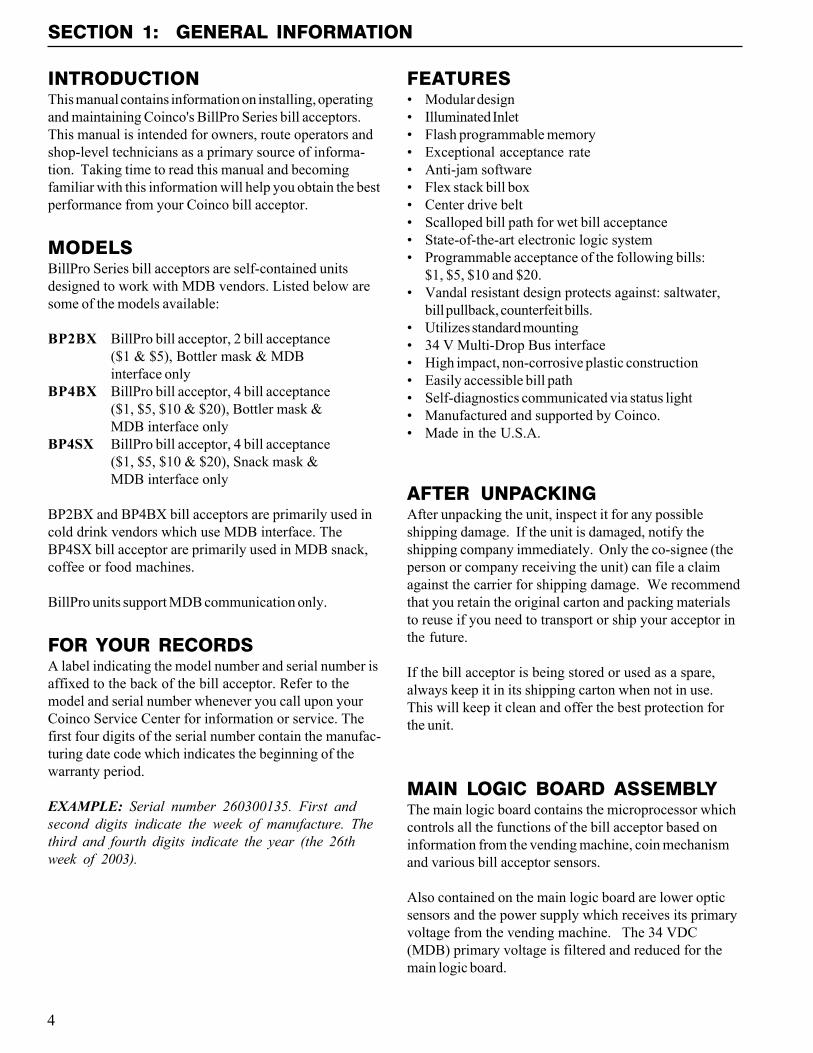
INTRODUCTIONThis manual contains information on installing, operatingand maintaining Coinco's BillPro Series bill acceptors.This manual is intended for owners, route operators andshop-level technicians as a primary source of informa-tion. Taking time to read this manual and becomingfamiliar with this information will help you obtain the bestperformance from your Coinco bill acceptor.
MODELSBillPro Series bill acceptors are self-contained unitsdesigned to work with MDB vendors. Listed below aresome of the models available:
BP2BX BillPro bill acceptor, 2 bill acceptance($1 & $5), Bottler mask & MDBinterface only
BP4BX BillPro bill acceptor, 4 bill acceptance($1, $5, $10 & $20), Bottler mask &MDB interface only
BP4SX BillPro bill acceptor, 4 bill acceptance($1, $5, $10 & $20), Snack mask &MDB interface only
BP2BX and BP4BX bill acceptors are primarily used incold drink vendors which use MDB interface. TheBP4SX bill acceptor are primarily used in MDB snack,coffee or food machines.
BillPro units support MDB communication only.
FOR YOUR RECORDSA label indicating the model number and serial number isaffixed to the back of the bill acceptor. Refer to themodel and serial number whenever you call upon yourCoinco Service Center for information or service. Thefirst four digits of the serial number contain the manufac-turing date code which indicates the beginning of thewarranty period.
EXAMPLE: Serial number 260300135. First andsecond digits indicate the week of manufacture. Thethird and fourth digits indicate the year (the 26thweek of 2003).
FEATURES� Modular design� Illuminated Inlet� Flash programmable memory� Exceptional acceptance rate� Anti-jam software� Flex stack bill box� Center drive belt� Scalloped bill path for wet bill acceptance� State-of-the-art electronic logic system� Programmable acceptance of the following bills:
$1, $5, $10 and $20.� Vandal resistant design protects against: saltwater,
bill pullback, counterfeit bills.� Utilizes standard mounting� 34 V Multi-Drop Bus interface� High impact, non-corrosive plastic construction� Easily accessible bill path� Self-diagnostics communicated via status light� Manufactured and supported by Coinco.� Made in the U.S.A.
AFTER UNPACKINGAfter unpacking the unit, inspect it for any possibleshipping damage. If the unit is damaged, notify theshipping company immediately. Only the co-signee (theperson or company receiving the unit) can file a claimagainst the carrier for shipping damage. We recommendthat you retain the original carton and packing materialsto reuse if you need to transport or ship your acceptor inthe future.
If the bill acceptor is being stored or used as a spare,always keep it in its shipping carton when not in use.This will keep it clean and offer the best protection forthe unit.
MAIN LOGIC BOARD ASSEMBLYThe main logic board contains the microprocessor whichcontrols all the functions of the bill acceptor based oninformation from the vending machine, coin mechanismand various bill acceptor sensors.
Also contained on the main logic board are lower opticsensors and the power supply which receives its primaryvoltage from the vending machine. The 34 VDC(MDB) primary voltage is filtered and reduced for themain logic board.
5
SECTION 1: GENERAL INFORMATION
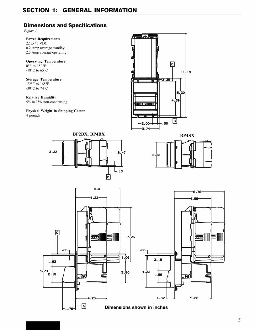
Dimensions and SpecificationsFigure 1
Power Requirements22 to 45 VDC0.2 Amp average standby2.5 Amp average operating
Operating Temperature0°F to 150°F-18°C to 65°C
Storage Temperature-22°F to 165°F-30°C to 74°C
Relative Humidity5% to 95% non-condensing
Physical Weight in Shipping Carton4 pounds
Dimensions shown in inches
BP2BX, BP4BX BP4SX
6
Anti-cheat lever
Inlet LEDs
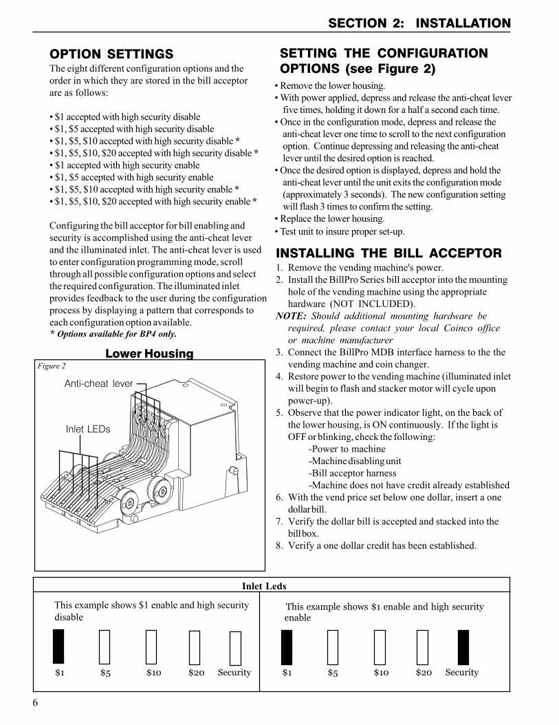
OPTION SETTINGSThe eight different configuration options and theorder in which they are stored in the bill acceptorare as follows:
� $1 accepted with high security disable� $1, $5 accepted with high security disable� $1, $5, $10 accepted with high security disable *� $1, $5, $10, $20 accepted with high security disable *� $1 accepted with high security enable� $1, $5 accepted with high security enable� $1, $5, $10 accepted with high security enable *� $1, $5, $10, $20 accepted with high security enable *
Configuring the bill acceptor for bill enabling andsecurity is accomplished using the anti-cheat leverand the illuminated inlet. The anti-cheat lever is usedto enter configuration programming mode, scrollthrough all possible configuration options and selectthe required configuration. The illuminated inletprovides feedback to the user during the configurationprocess by displaying a pattern that corresponds toeach configuration option available.
SECTION 2: INSTALLATION
Figure 2
INSTALLING THE BILL ACCEPTOR1. Remove the vending machine's power.2. Install the BillPro Series bill acceptor into the mounting
hole of the vending machine using the appropriatehardware (NOT INCLUDED).
NOTE: Should additional mounting hardware berequired, please contact your local Coinco officeor machine manufacturer
3. Connect the BillPro MDB interface harness to the thevending machine and coin changer.
4. Restore power to the vending machine (illuminated inletwill begin to flash and stacker motor will cycle uponpower-up).
5. Observe that the power indicator light, on the back ofthe lower housing, is ON continuously. If the light isOFF or blinking, check the following:
-Power to machine-Machine disabling unit-Bill acceptor harness-Machine does not have credit already established
6. With the vend price set below one dollar, insert a onedollar bill.
7. Verify the dollar bill is accepted and stacked into thebill box.
8. Verify a one dollar credit has been established.
Lower Housing
$1 $5 $10 $20 Security $1 $5 $10 $20 Security
� Remove the lower housing.� With power applied, depress and release the anti-cheat lever
five times, holding it down for a half a second each time.� Once in the configuration mode, depress and release the
anti-cheat lever one time to scroll to the next configurationoption. Continue depressing and releasing the anti-cheatlever until the desired option is reached.
� Once the desired option is displayed, depress and hold theanti-cheat lever until the unit exits the configuration mode(approximately 3 seconds). The new configuration settingwill flash 3 times to confirm the setting.
� Replace the lower housing.� Test unit to insure proper set-up.
SETTING THE CONFIGURATIONOPTIONS (see Figure 2)
* Options available for BP4 only.
This example shows $1 enable and high security disable
This example shows $1 enable and high security enable
Inlet Leds
7
BILL RECOGNITIONWhen a bill is inserted into the bill acceptor and it blocksthe left and right alignment sensors as well as the centeroptic sensor, the transport motor begins to run.
BILL VALIDATIONFrom the time the transport motor begins to run until thetrailing edge of the bill leaves the alignment sensors,optical and magnetic sensors send information to themicroprocessor to determine the validity of the bill.
BILL STACKING AND CREDITIf the bill is determined to be authentic, it is transported tothe stack position. Once the sensors of the lowerhousing�s anti-pullback lever signals the microprocessorthat the bill is in the stacking position, the stacker motorruns and credit is given.
BILL REJECTIONIf the bill is determined to be invalid, the wrong denomi-nation or the anti-pullback levers are active when the billis determined to be in the stack position, the transportmotor will reverse returning the bill to the customer.
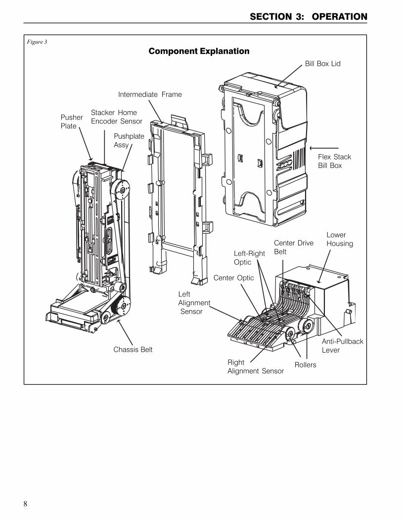
COMPONENT EXPLANATION(see Figure 3)
Bill Transport and StackingThe bill transport system is composed of a motor andgearcase assembly and two sets of pulleys and belts.When the transport motor is energized, it pulls the bill inby sandwiching it between the lower housing rollers andthe chassis belts. During the validation process, the bill istransferred from the lower housing rollers and chassisbelts to the intermediate frame and rollers.
The bill stacker is composed of a motor and gearcaseassembly and a pusher plate assembly. When the bill istransported past the anti-pullback levers into the stackingposition, the stacker motor energizes driving the pusherplate, which in turn, pushes the bill into the bill box.
Left and Right Alignment SensorsThe left and right alignment sensors send information tothe microprocessor to insure that the bill is the right widthand that it is being fed in correctly.
Center Optic SensorThe center optic sensor informs the microprocessor thatthe bill is ready to be transported if the information fromthe alignment sensors is correct.
Left and Right Optic SensorsThe left and right optic sensors and associated circuitryperform various optical checks on the bill and send thatinformation to the microprocessor for bill validation.
Magnetic SensorThe magnetic sensor and its associated circuitry per-forms checks on the magnetic properties of the bill andsends that information to the microprocessor for billvalidation.
Anti-Pullback LeverThe lower anti-pullback lever is optically monitored to tellthe microprocessor when the bill has entered the stackposition or if an attempt to defraud the unit is takingplace.
Stacker Home SensorThe stacker home sensor is an optical sensor thatinforms the microprocessor of the position of the stackerpusher plate.
Encoder SensorConnected to the transport motor is an encoder wheelwhich is optically monitored to determine the speed ofthe transport motor and to determine the position of thebill in the bill path.
SECTION 3: OPERATION
8
SECTION 3: OPERATION
Figure 3
Component ExplanationBill Box Lid
Intermediate Frame
Flex StackBill Box
LowerHousingCenter Drive
Belt
LeftAlignment Sensor
Chassis BeltAnti-PullbackLever
PusherPlate
Stacker HomeEncoder Sensor
RightAlignment Sensor
PushplateAssy
Center Optic
Left-RightOptic
Rollers
9
SECTION 3: OPERATION
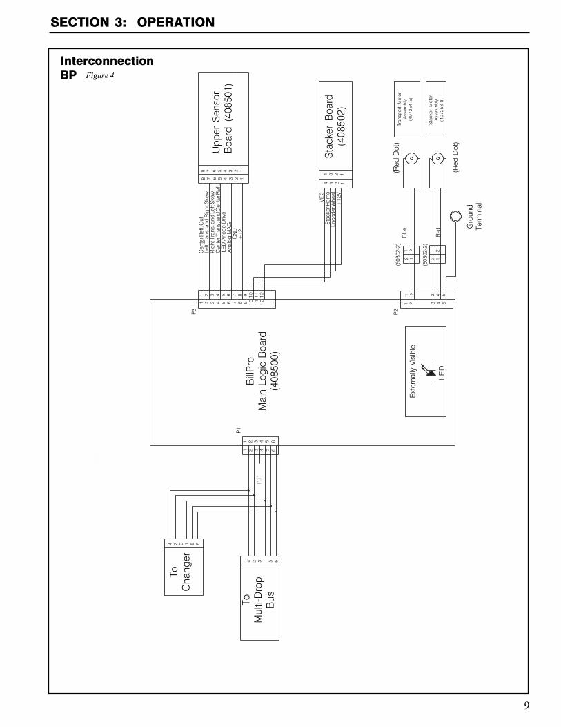
InterconnectionBP
Bill
Pro
Mai
n Lo
gic
Boa
rd(4
0850
0)
ToC
hang
er
ToM
ulti-
Dro
pB
us
Upp
er S
enso
rB
oard
(40
8501
)
Sta
cker
Boa
rd(4
0850
2)
8 7 6 5 4 3 2 1
8 7 6 5 4 3 2 1
4 3 2 1
4 3 2 1
Tran
spor
t M
otor
Ass
embl
y(4
0725
4-5)
Sta
cker
Mot
orA
sses
mbl
y(4
0725
3-8)
(Red
Dot
)
(Red
Dot
)
Gro
und
Term
inal
(603
02-2
)
(603
02-2
)
Blu
e
Red
221
1 2 121
2121
3 4 5
3 4 5
P2
Ext
erna
lly V
isib
le
LED
VE2
+12
VE
ncod
er W
heel
Sta
cker
Hom
e
1 2 3 4 5 6
1 2 3 4 5 6
P1
P.P
4 2 3 1 5 6
4 2 3 1 5 6
1 2 3 4 5 6 7 8 9 10
11
12
1 2 3 4 5 6 7 8 9 10
11
12
P3
+12
GN
DA
nalo
g M
AG
LED
Ano
de D
rive
Cen
ter T
rans
. and
Cen
ter R
efl.
Rig
ht T
rans
. and
Lef
t Ske
wLe
ft Tr
ans.
and
Rig
ht S
kew
Cen
ter R
efl.
Out
Figure 4
10
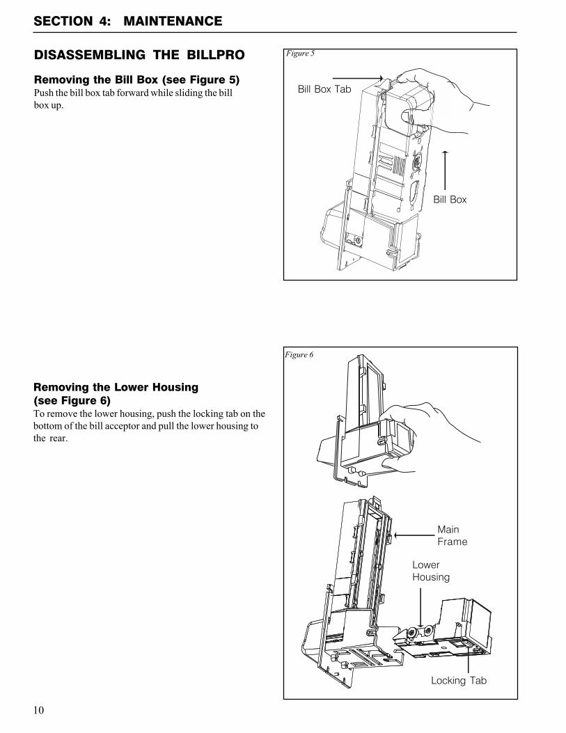
DISASSEMBLING THE BILLPRO
Removing the Bill Box (see Figure 5)Push the bill box tab forward while sliding the billbox up.
Figure 5
Bill Box Tab
Removing the Lower Housing(see Figure 6)To remove the lower housing, push the locking tab on thebottom of the bill acceptor and pull the lower housing tothe rear.
SECTION 4: MAINTENANCE
Figure 6
MainFrame
Locking Tab
LowerHousing
Bill Box
11
SECTION 4: MAINTENANCE
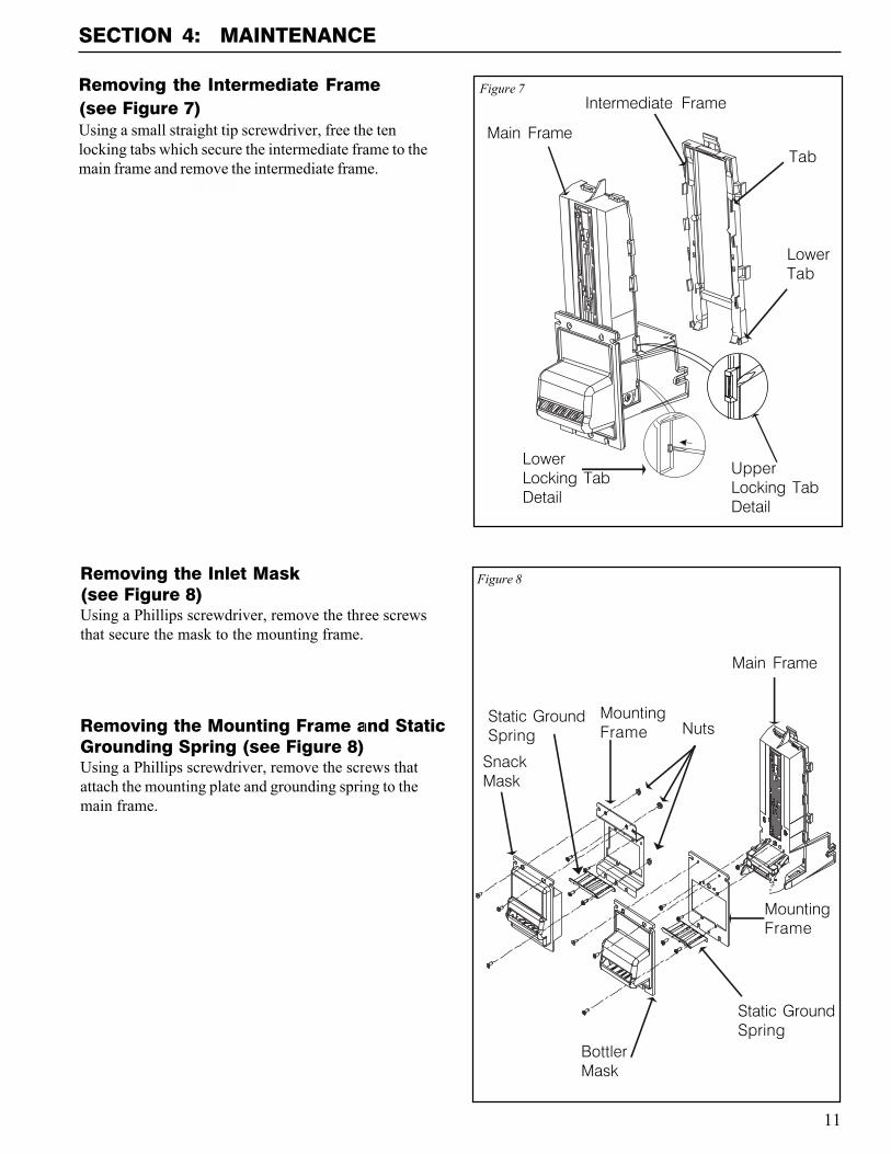
Removing the Inlet Mask(see Figure 8)Using a Phillips screwdriver, remove the three screwsthat secure the mask to the mounting frame.
Removing the Mounting Frame and StaticGrounding Spring (see Figure 8)Using a Phillips screwdriver, remove the screws thatattach the mounting plate and grounding spring to themain frame.
Figure 8
Main Frame
BottlerMask
SnackMask
MountingFrame
MountingFrame
Static GroundSpring
Static GroundSpring Nuts
Main Frame
Intermediate FrameFigure 7
Tab
LowerLocking TabDetail
UpperLocking TabDetail
LowerTab
Removing the Intermediate Frame(see Figure 7)Using a small straight tip screwdriver, free the tenlocking tabs which secure the intermediate frame to themain frame and remove the intermediate frame.
12
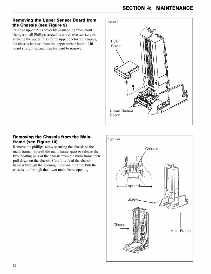
Removing the Chassis from the Main-frame (see Figure 10)Remove the phillips screw securing the chassis to themain frame. Spread the main frame apart to release thetwo locating pins of the chassis from the main frame thenpull down on the chassis. Carefully feed the chassisharness through the opening in the main frame. Pull thechassis out through the lower main frame opening.
Figure 10
Main Frame
Chassis
Chassis
Figure 9Removing the Upper Sensor Board fromthe Chassis (see Figure 9)Remove upper PCB cover by unsnapping from front.Using a small Phillips screwdriver, remove two screwssecuring the upper PCB to the upper enclosure. Unplugthe chassis harness from the upper sensor board. Liftboard straight up and then forward to remove.
Upper SensorBoard
SECTION 4: MAINTENANCE
Screw
PCBCover
spread
13
SECTION 4: MAINTENANCE
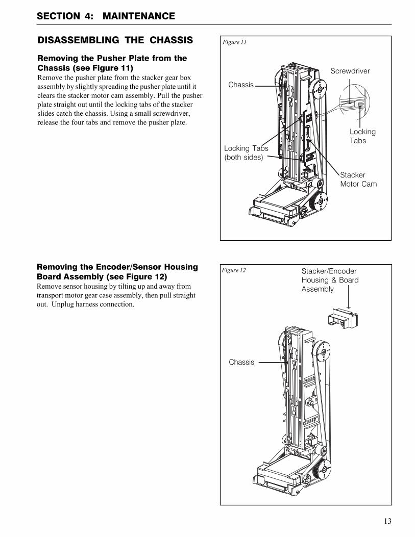
Removing the Encoder/Sensor HousingBoard Assembly (see Figure 12)Remove sensor housing by tilting up and away fromtransport motor gear case assembly, then pull straightout. Unplug harness connection.
Figure 12 Stacker/EncoderHousing & BoardAssembly
Chassis
DISASSEMBLING THE CHASSIS
Removing the Pusher Plate from theChassis (see Figure 11)Remove the pusher plate from the stacker gear boxassembly by slightly spreading the pusher plate until itclears the stacker motor cam assembly. Pull the pusherplate straight out until the locking tabs of the stackerslides catch the chassis. Using a small screwdriver,release the four tabs and remove the pusher plate.
Figure 11
Chassis
Locking Tabs(both sides)
LockingTabs
Screwdriver
StackerMotor Cam
14
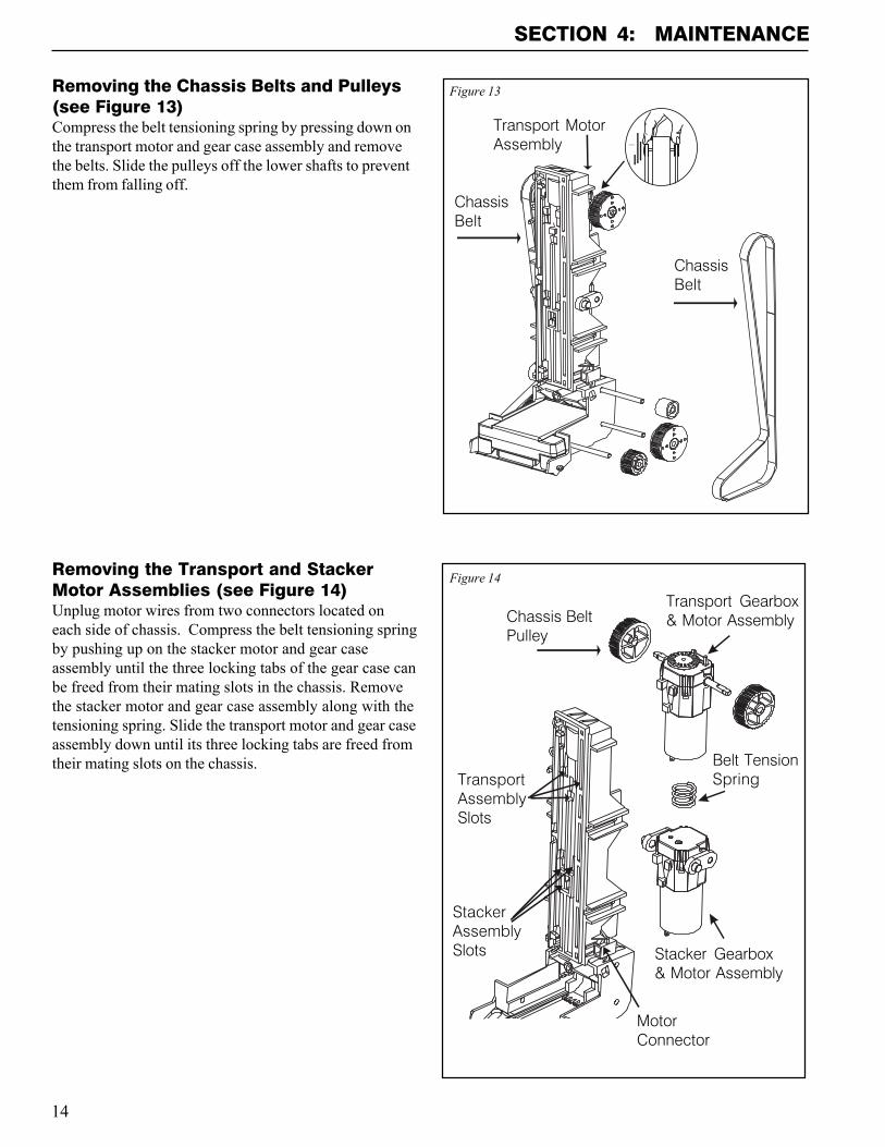
Removing the Transport and StackerMotor Assemblies (see Figure 14)Unplug motor wires from two connectors located oneach side of chassis. Compress the belt tensioning springby pushing up on the stacker motor and gear caseassembly until the three locking tabs of the gear case canbe freed from their mating slots in the chassis. Removethe stacker motor and gear case assembly along with thetensioning spring. Slide the transport motor and gear caseassembly down until its three locking tabs are freed fromtheir mating slots on the chassis.
Removing the Chassis Belts and Pulleys(see Figure 13)Compress the belt tensioning spring by pressing down onthe transport motor and gear case assembly and removethe belts. Slide the pulleys off the lower shafts to preventthem from falling off.
SECTION 4: MAINTENANCE
Figure 14
Chassis BeltPulley
Belt TensionSpring
Stacker Gearbox& Motor Assembly
TransportAssemblySlots
StackerAssemblySlots
Transport Gearbox& Motor Assembly
Figure 13
ChassisBelt
ChassisBelt
Transport MotorAssembly
MotorConnector
15
SECTION 4: MAINTENANCE
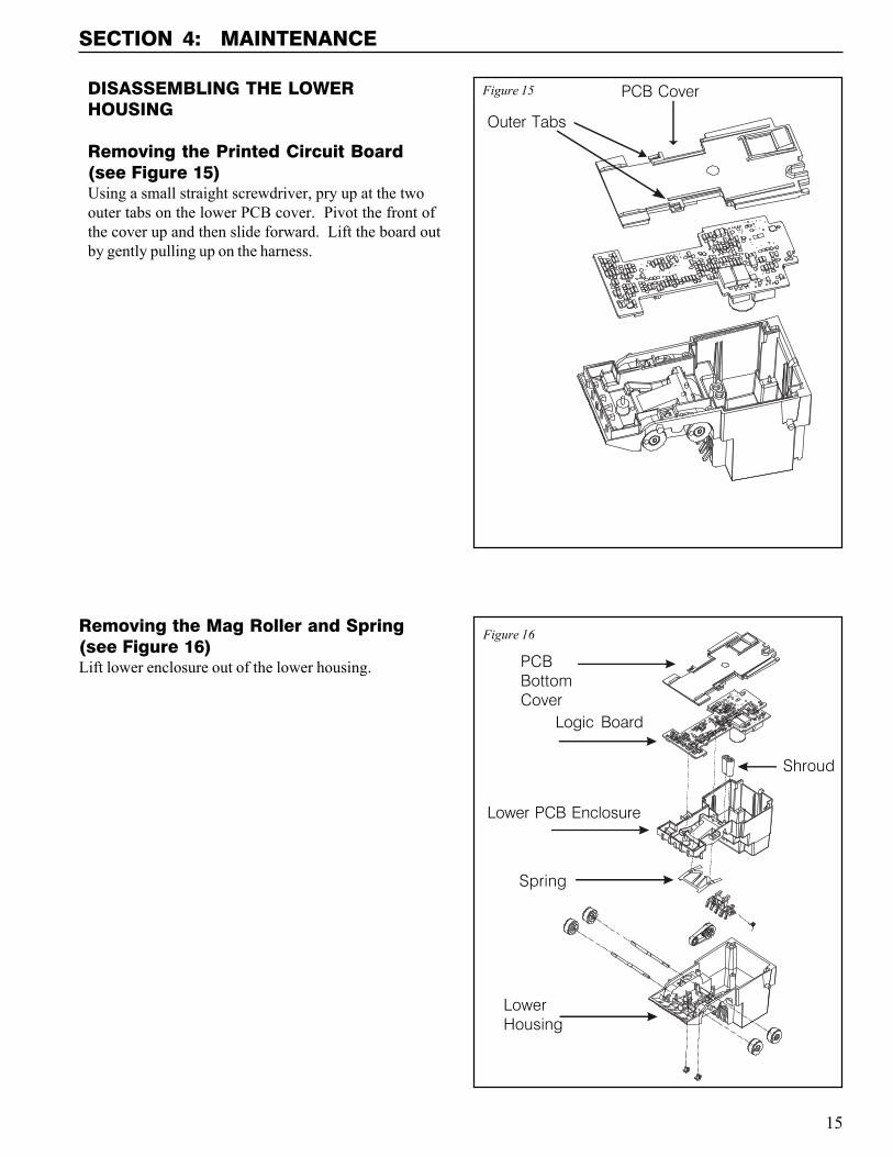
Removing the Mag Roller and Spring(see Figure 16)Lift lower enclosure out of the lower housing.
Figure 15
Figure 16
DISASSEMBLING THE LOWERHOUSING
Removing the Printed Circuit Board(see Figure 15)Using a small straight screwdriver, pry up at the twoouter tabs on the lower PCB cover. Pivot the front ofthe cover up and then slide forward. Lift the board outby gently pulling up on the harness.
PCBBottomCover
LowerHousing
Logic Board
Shroud
Spring
Lower PCB Enclosure
PCB Cover
Outer Tabs
16
SECTION 4: MAINTENANCE
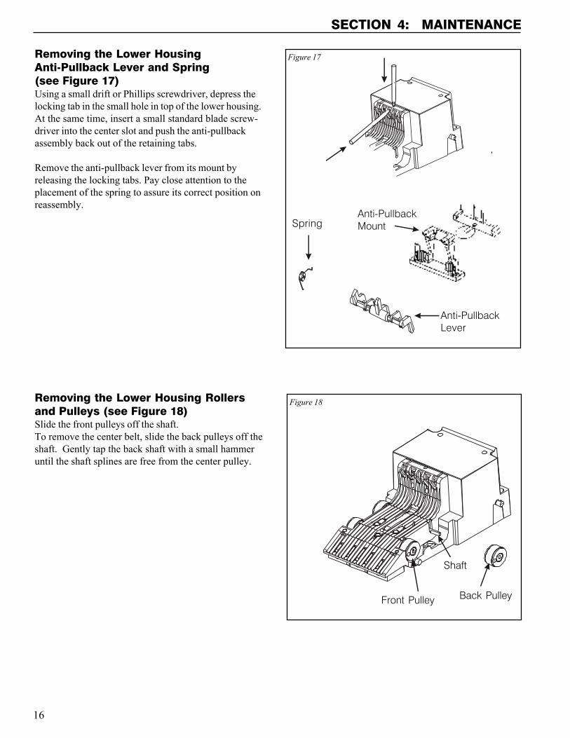
Removing the Lower HousingAnti-Pullback Lever and Spring(see Figure 17)Using a small drift or Phillips screwdriver, depress thelocking tab in the small hole in top of the lower housing.At the same time, insert a small standard blade screw-driver into the center slot and push the anti-pullbackassembly back out of the retaining tabs.
Remove the anti-pullback lever from its mount byreleasing the locking tabs. Pay close attention to theplacement of the spring to assure its correct position onreassembly.
Removing the Lower Housing Rollersand Pulleys (see Figure 18)Slide the front pulleys off the shaft.To remove the center belt, slide the back pulleys off theshaft. Gently tap the back shaft with a small hammeruntil the shaft splines are free from the center pulley.
Figure 18
Back Pulley
Shaft
Front Pulley
Figure 17
Anti-PullbackLever
SpringAnti-PullbackMount
17
SECTION 4: MAINTENANCE
BILLPRO CLEANING PROCEDUREFOR SALT WATER POLLUTEDUNITSNOTE: Petroleum-based cleaners and freon-basedpropellants can damage plastic and some electroniccomponents. Scouring pads and stiff brushes mayharm the circuit boards and mar the plastic. Theseitems should never be used when cleaning the BillProbill acceptor.
Procedure1. Remove power from the bill acceptor.2. Remove the bill acceptor from the vending machine.3. Open the bill box lid and verify that the stacker plate
is in the standby/home position. If it is not in thehome position, apply power and observe that thestacker plate returns home.
4. Remove the bill box.
WARNING: If moisture is present, allow the unit todry thoroughly before applying power to avoidpossible shock hazard. If the stacker plate does notreturn to the home position, remove power andcarefully remove the bill box to avoid damaging thebill box and/or stacker plate.
5. Remove the lower housing.6. Remove the bottom cover of the lower housing.7. Run hot water (110°-140°F) over the lower housing
from the top. Using a soft brush, gently clean anysalt residue. Use a soft, absorbent cloth to cleanresidue off the lower housing. Allow the unit to dryfor 24 hours before applying power.
8. Remove the front mask. Using hot water and a softbrush, clean the front mask, upper sensor boardcover and main frame anti-pullback levers.
CAUTION: The motors are not protected from water,therefore the unit must be held in a manner thatprevents water from running over them.
9. Verify the anti-pullback levers move freely and thatthe spring returns them to their extended position.
10. Allow the unit to dry thoroughly.11. Clean the magnetic head using a swab and isopropyl
alcohol.12. Replace the front mask.13 Replace the lower housing cover.14. Place the lower housing into the main frame.15. Remount the bill box.16. Apply power and insert bills to verify the unit is
functioning properly.
BILLPRO CLEANINGMAINTENANCE PROCEDURENOTE: Petroleum-based cleaners and freon-basedpropellants can damage plastic and some electroniccomponents. Scouring pads and stiff brushes mayharm the circuit boards and mar the plastic. Theseitems should never be used when cleaning the BillProbill acceptor.
The BillPro should be cleaned every 20,000 bills or everytwo years (or as needed, depending on the environmentalconditions of the location). Dust can be removed with asoft brush or cloth or it can be blown out using com-pressed air.
Procedure1. Disconnect power from the bill acceptor.2. Remove the bill box and use a soft cloth to wipe any
dust from around the intermediate frame andstacker plate.
3. Remove the lower housing.4. Using compressed air or a soft brush, blow or brush
the dust off of the optic sensors.5. Remove dust from around the rollers on the lower
housing and the sensors on the upper sensor board.The upper sensors are located directly above thelower housing sensors when the lower housing isinstalled.
6. The bill path can be further cleaned of any dirt or oilby using a soft cloth moistened with a mild soap andwater solution.
7. Clean the magnetic head with a cotton swab andisopropyl alcohol.
8. Remove dust from the transport belt areas and anyother places of build up.
9. Once the lower housing is dry, place it back into themainframe making sure the tab on the bottom locksinto place.
10. Remount the bill box.11. Apply power and insert bills to verify the unit is
functioning properly.
18
SECTION 5: TROUBLESHOOTING
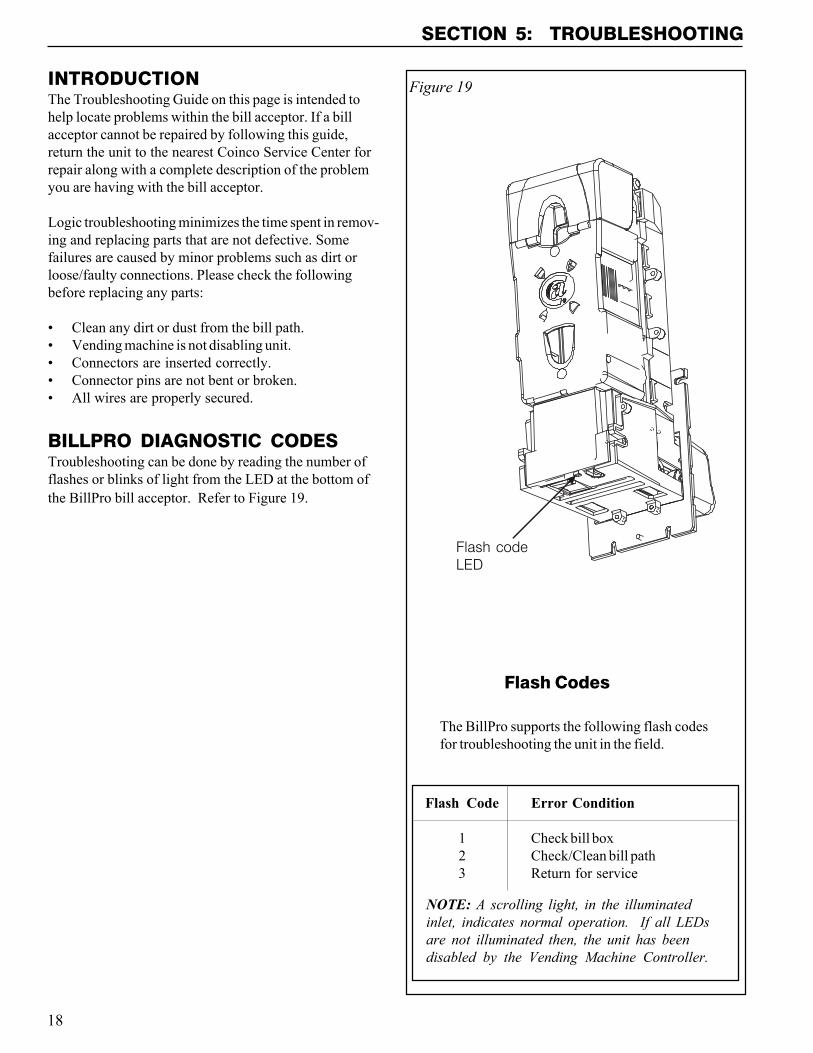
INTRODUCTIONThe Troubleshooting Guide on this page is intended tohelp locate problems within the bill acceptor. If a billacceptor cannot be repaired by following this guide,return the unit to the nearest Coinco Service Center forrepair along with a complete description of the problemyou are having with the bill acceptor.
Logic troubleshooting minimizes the time spent in remov-ing and replacing parts that are not defective. Somefailures are caused by minor problems such as dirt orloose/faulty connections. Please check the followingbefore replacing any parts:
� Clean any dirt or dust from the bill path.� Vending machine is not disabling unit.� Connectors are inserted correctly.� Connector pins are not bent or broken.� All wires are properly secured.
BILLPRO DIAGNOSTIC CODESTroubleshooting can be done by reading the number offlashes or blinks of light from the LED at the bottom ofthe BillPro bill acceptor. Refer to Figure 19.
Flash Code Error Condition
1 Check bill box2 Check/Clean bill path3 Return for service
NOTE: A scrolling light, in the illuminatedinlet, indicates normal operation. If all LEDsare not illuminated then, the unit has beendisabled by the Vending Machine Controller.
Figure 19
Flash codeLED
Flash Codes
The BillPro supports the following flash codesfor troubleshooting the unit in the field.
19
SECTION 6: PARTS LIST
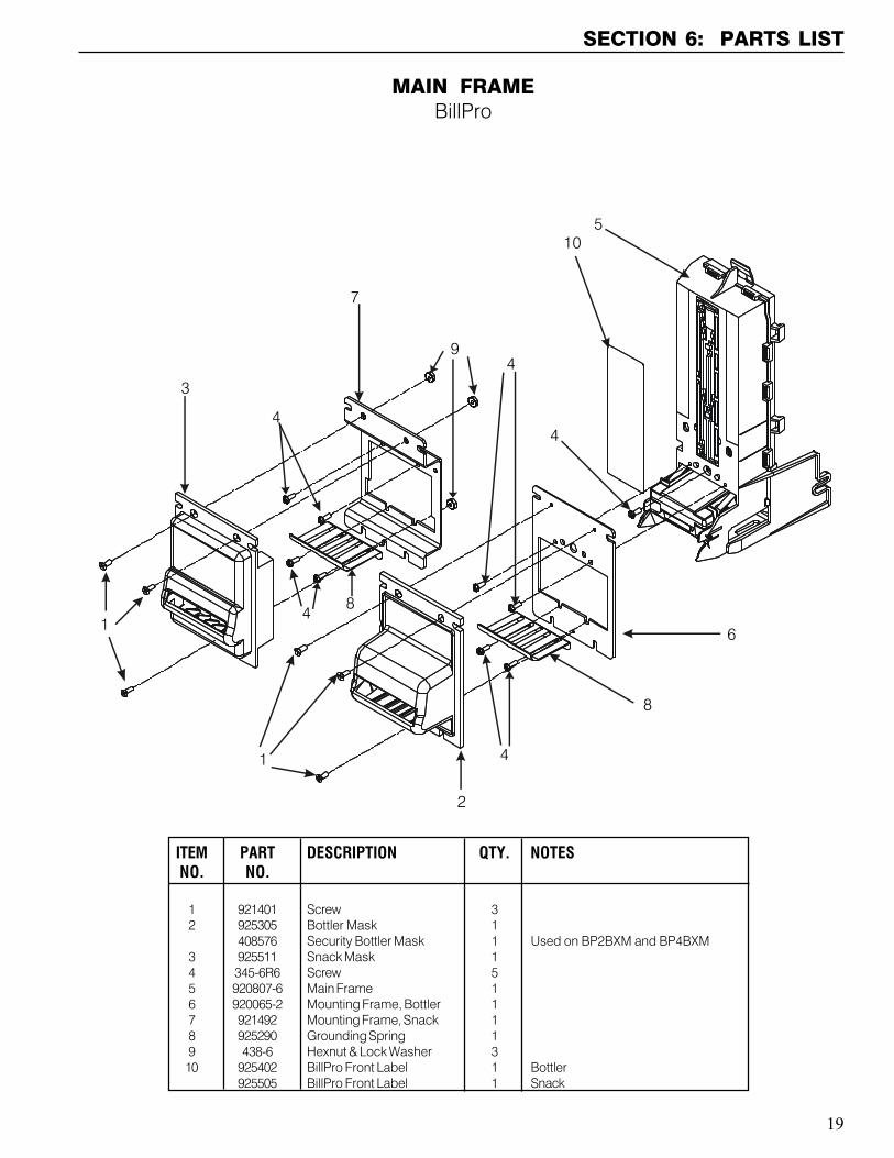
MAIN FRAMEBillPro
ITEM PART DESCRIPTION QTY. NOTESNO. NO.
1 921401 Screw 32 925305 Bottler Mask 1
408576 Security Bottler Mask 1 Used on BP2BXM and BP4BXM3 925511 Snack Mask 14 345-6R6 Screw 55 920807-6 Main Frame 16 920065-2 Mounting Frame, Bottler 17 921492 Mounting Frame, Snack 18 925290 Grounding Spring 19 438-6 Hexnut & Lock Washer 310 925402 BillPro Front Label 1 Bottler
925505 BillPro Front Label 1 Snack
1
1
4
4
4
4
4
3
5
6
9
2
8
7
8
10
20
SECTION 6: PARTS LIST
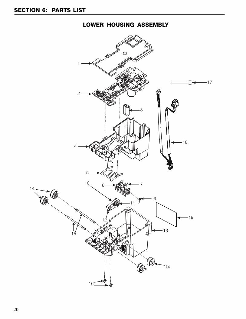
LOWER HOUSING ASSEMBLY
11
15
18
3
13
12
1014
7
5
19
17
4
2
6
16
14
1
8
21
SECTION 6: PARTS LIST
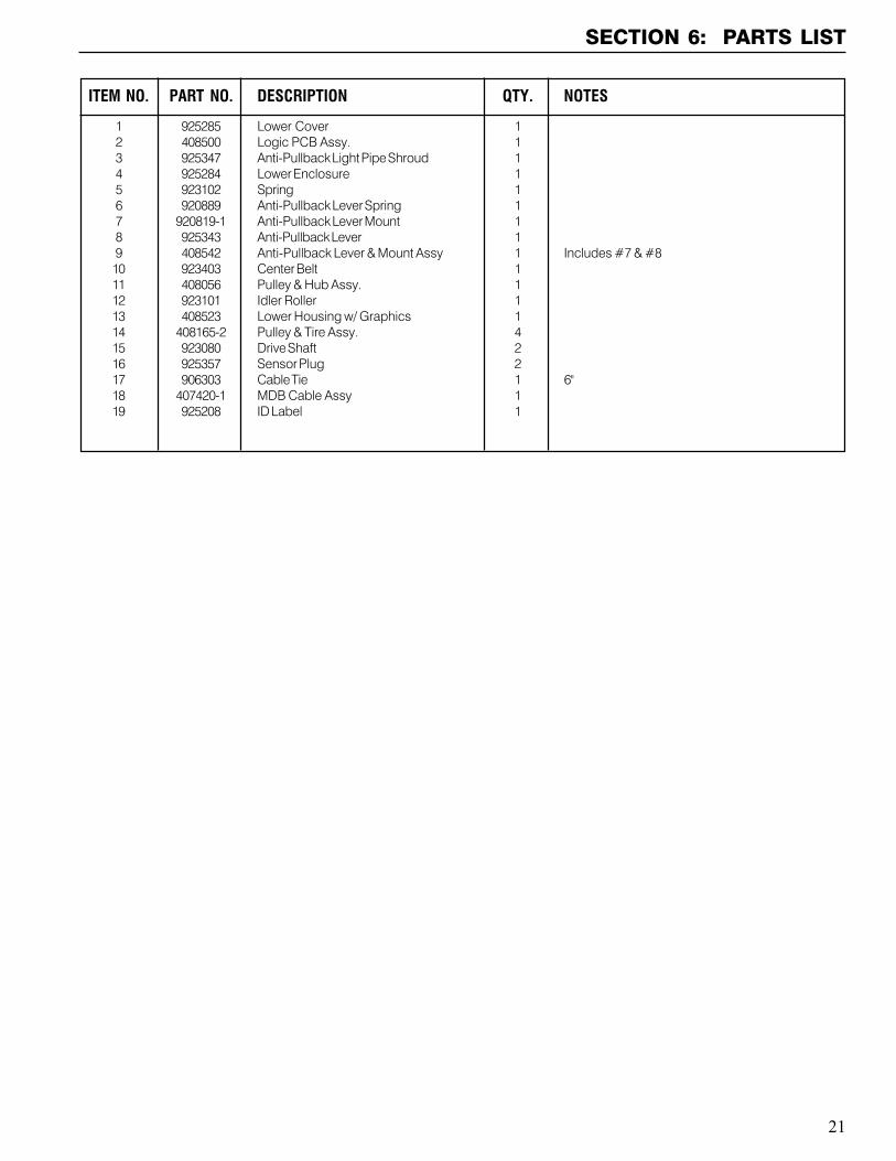
ITEM NO. PART NO. DESCRIPTION QTY. NOTES
1 925285 Lower Cover 12 408500 Logic PCB Assy. 13 925347 Anti-Pullback Light Pipe Shroud 14 925284 Lower Enclosure 15 923102 Spring 16 920889 Anti-Pullback Lever Spring 17 920819-1 Anti-Pullback Lever Mount 18 925343 Anti-Pullback Lever 19 408542 Anti-Pullback Lever & Mount Assy 1 Includes #7 & #810 923403 Center Belt 111 408056 Pulley & Hub Assy. 112 923101 Idler Roller 113 408523 Lower Housing w/ Graphics 114 408165-2 Pulley & Tire Assy. 415 923080 Drive Shaft 216 925357 Sensor Plug 217 906303 Cable Tie 1 6"18 407420-1 MDB Cable Assy 119 925208 ID Label 1
22
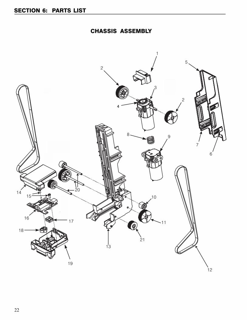
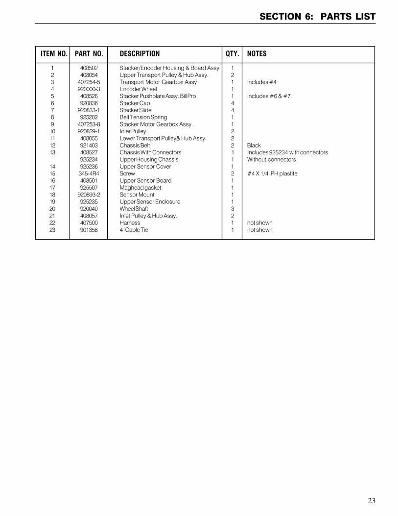
CHASSIS ASSEMBLY
1
2
2
34
5
7
6
8 9
10
10
11
11
12
12
13
1415
1516
17
18
19
20
21
21
SECTION 6: PARTS LIST
4
23
SECTION 6: PARTS LIST
ITEM NO. PART NO. DESCRIPTION QTY. NOTES
1 408502 Stacker/Encoder Housing & Board Assy. 12 408054 Upper Transport Pulley & Hub Assy. 23 407254-5 Transport Motor Gearbox Assy 1 Includes #44 920000-3 Encoder Wheel 15 408526 Stacker Pushplate Assy. BillPro 1 Includes #6 & #76 920836 Stacker Cap 47 920833-1 Stacker Slide 48 925202 Belt Tension Spring 19 407253-8 Stacker Motor Gearbox Assy. 110 920829-1 Idler Pulley 211 408055 Lower Transport Pulley& Hub Assy. 212 921403 Chassis Belt 2 Black13 408527 Chassis With Connectors 1 Includes 925234 with connectors
925234 Upper Housing Chassis 1 Without connectors14 925236 Upper Sensor Cover 115 345-4R4 Screw 2 #4 X 1/4 PH plastite16 408501 Upper Sensor Board 117 925507 Maghead gasket 118 920893-2 Sensor Mount 119 925235 Upper Sensor Enclosure 120 920040 Wheel Shaft 321 408057 Inlet Pulley & Hub Assy. 222 407500 Harness 1 not shown23 901358 4" Cable Tie 1 not shown
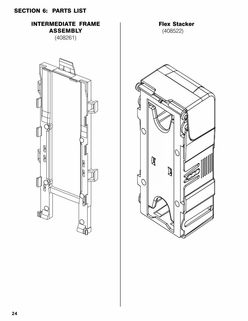
INTERMEDIATE FRAMEASSEMBLY
(408261)
Flex Stacker (408522)
SECTION 6: PARTS LIST
24


COIN ACCEPTORS, INC.300 Hunter AvenueSt. Louis, MO 63124-2013(314) 725-0100 or (800) 325-2646
Coinco Publication No. 925495 Rev.103/2004 Printed in the U.S.A.