Bild in der Größe 215x70 mm einfügen - CEM Viano-Vito_uk.pdf · Bild in der Größe 215x70 mm...
63
Vito / Viano Taxi supplement
Transcript of Bild in der Größe 215x70 mm einfügen - CEM Viano-Vito_uk.pdf · Bild in der Größe 215x70 mm...

Bild in der Größe215x70 mm einfügen
Vito/Viano Taxi supplement
Order no. 6462 2526 02 Part no. 639 584 12 81 EN Edition A 05/03

Bild in der Größe215x70 mm einfügen
Vito/Viano Taxi supplement
Order no. 6462 2526 02 Part no. 639 584 12 81 EN Edition A 05/03

Thank you for choosing a Mercedes-Benz vehicle with special taxi equipment.
Before you operate the taxi-specific equip-ment and systems, familiarise yourself with your taxi's special equipment and read this supplement. This will help you to obtain the maximum pleasure from your vehicle and to avoid endangering yourself and others.
Items of special equipment are marked with an asterisk *.
The taxi-specific equipment in your vehicle may vary, depending on the model, the country specifications and availability.
Mercedes-Benz is constantly updating its vehicles to the state of the art and there-fore reserves the right to introduce chang-es in design, equipment and technical features at any time. Claims based on the data, illustrations or descriptions in this supplement cannot, therefore, be enter-tained.
The nearest Mercedes-Benz Service Cen-tre will be happy to help should you have any questions.
This supplement is an integral part of your vehicle. You should always keep it in the vehicle and pass it on to the new owner if you sell the vehicle.
The technical documentation team at Mercedes-Benz wishes you safe and pleas-ant motoring.
Risk of injury G
This supplement in no way replaces the de-tailed Owner's Manual. This is especially im-portant with regard to warning notes. Before you drive off, please read with the detailed Owner's Manual, particularly the "Safety" section.
You may otherwise fail to recognise dangers and injure yourself or others.
Contact
Mercedes-Benz will be happy to answer any questions you may have:
Mercedes-Benz Contact Telephone: 00800 1 777 7777International: +49 69 95 30 72 77
Internet
Further information about Mercedes-Benz vehicles and DaimlerChrysler can be found on the following websites:
www.mercedes-benz.comwww.daimlerchrysler.com
Editorial office
You are welcome to forward any queries or suggestions you might have about this supplement to the technical documentation team at the following address:
DaimlerChrysler AG, HPC: R803, 70546 Stuttgart, Germany
As at: 20.03.2003
Title illustration: P00.01-2254-31
Not to be reprinted, translated or otherwise reproduced, in whole or in part, without written permission.

Contents
Introduction
The aim of this supplement . . . . . . . . 3
Symbols . . . . . . . . . . . . . . . . . . . . . . . . 4Operating safety . . . . . . . . . . . . . . . . . 5
Retrofitting electrical and electronic equipment . . . . . . . . . . . . . . . . . . . . 5Operation of mobile phones and two-way radios . . . . . . . . . . . . . . . . . 7
1 At a glance
Cockpit . . . . . . . . . . . . . . . . . . . . . . . . 10
2 Controls in detail
Two-way radio with hands-free facility . . . . . . . . . . . . . . . . . . . . . . . . . 14
Transmitter button . . . . . . . . . . . . . 14Electret microphone . . . . . . . . . . . . 15Two-way radio loudspeaker . . . . . . 15
Taxi roof sign illumination . . . . . . . . 16Activating power supply . . . . . . . . . 17Switching off. . . . . . . . . . . . . . . . . . 17
Two-way radio operation. . . . . . . . . . 18
3 Practical advice
Troubleshooting . . . . . . . . . . . . . . . . . 20Messages in the multifunction display (High-Line)* . . . . . . . . . . . . 20
Changing the batteries . . . . . . . . . . . 24Changing the radio remote control batteries . . . . . . . . . . . . . . . . . . . . . 24
Fuses . . . . . . . . . . . . . . . . . . . . . . . . . . 26Installing the taximeter. . . . . . . . . . . 27
Installing a taximeter in the lower section of the centre console* . . . . 27Installing the mirror taximeter* . . . 29
Installing the two-way radio . . . . . . . 31Installing a two-way radio in the lower section of the centre console* . . . . . . . . . . . . . . . . . . . . . 31Installing the two-way radio in the centre console . . . . . . . . . . . . . . . . 32
Connecting peripherals . . . . . . . . . . . 35Fitting the taxi roof sign . . . . . . . . . . 37
Fitting the taxi roof sign . . . . . . . . . 37Connectors . . . . . . . . . . . . . . . . . . . . . 39
Connector socket for taxi roof sign . . . . . . . . . . . . . . . . . . . . . . . . . 39Connector for two-way radio aerial. . . . . . . . . . . . . . . . . . . . . . . . 39
Connector for two-way radio . . . . . 40Connector for taximeter . . . . . . . . . 41Connectors for mirror taximeter . . . 42Connectors for peripherals and HALE CEY system . . . . . . . . . . . . . . 43
Roof aerial. . . . . . . . . . . . . . . . . . . . . . 44Tuning the aerial rod to the transmitter frequency . . . . . . . . . . . 44Removing and refitting the aerial housing . . . . . . . . . . . . . . . . . . . . . . 45
4 Technical data
Order numbers . . . . . . . . . . . . . . . . . . 48Order numbers for electrical connection components . . . . . . . . . 48
Road speed signal . . . . . . . . . . . . . . . 50Output signal for taximeter. . . . . . . 50
Electret microphone . . . . . . . . . . . . . 52Coupling electronics . . . . . . . . . . . . 52Technical data. . . . . . . . . . . . . . . . . 53
5 Glossary and index
Technical terms . . . . . . . . . . . . . . . . . 55Index . . . . . . . . . . . . . . . . . . . . . . . . . . 57

Contents

3
The aim of this supplement
Introduction
The aim of this supplement
This supplement is intended to assist you in operating the taxi-specific equipment in your vehicle.
Each section has its own colour code to help you find the information you require quickly.
1 At a glance
Here you will find an overview of all the taxi-specific controls which can be oper-ated from the driver's seat.
2 Controls in detail
This is where you will find more detailed information about the taxi-specific equip-ment in your vehicle.
3 Practical advice
Here you will find help for any problems which might arise in connection with the installation of items of special taxi equip-ment.
4 Technical data
All the important technical data for the special taxi equipment is contained here.
5 Glossary and index
The glossary of technical terms explains the most important taxi-specific technical terms.
The table of contents and the index are intended to help you find information quickly.

4
Symbols
You will find the following symbols used in this supplement:
* Optional equipment is identified with an asterisk. The equipment in your vehicle may differ from some of the descriptions and illustrations you see here as not all models have the same standard equipment.
This symbol means that you have to do something.
A number of these symbols one after the other indicates a sequence of actions.
Page This symbol indicates on which page you can find further infor-mation on the subject.
This continuation symbol indi-cates an interrupted sequence of actions that will be continued on the next page.
Warning G
A warning note draws your attention to pos-sible risks of accident or injury to yourself or others.
Environmental note H
An environmental note gives you tips on the protection of the environment.
!This note draws your attention to possi-ble hazards to your vehicle.
iThis tip contains advice or further infor-mation you may find useful.

5
Operating safety
Operating safety
Electrical and electronic equipment which has been retrofitted can affect the opera-tional safety of your vehicle. If equipment of this kind is retrofitted, it must be type-approved and bear the e-mark.
If you wish to have mobile phones, two-way radios or fax machines installed in the vehicle, you must obtain formal approval.
Retrofitting electrical and electronic equipment Risk of accident G
Work carried out incorrectly on electronic equipment and its software could stop this equipment working. The electronic systems are interconnected through interfaces. Since the electronic systems are intercon-nected, intervention in these systems could also affect systems that have not been mod-ified.
Malfunctions such as these could jeopardise the operating and road safety of your vehi-cle.
They could also alter the driving and braking characteristics of your vehicle. You could cause an accident and endanger or injure yourself or others as a result.
Other work on or modifications to the vehi-cle which are carried out incorrectly may also impair the vehicle's operating safety.
For this reason, always have taximeters, control systems, printers or other electrical or electronic equipment retrofitted at a qual-ified specialist workshop which has the nec-essary specialist knowledge and tools to carry out the work required.

6
Operating safety
The installation of mobile phones, two-way radios or fax machines should only be car-ried out if the maximum transmission out-puts listed below are not exceeded.
Always have this type of equipment profes-sionally installed in accordance with the instructions in this supplement, and fitted with an external aerial which has been tuned to be reflection-free.
For reasons of safety and the electro-magnetic compatibility of the vehicle, Mercedes-Benz recommend that you only operate electrical or electronic equipment which fulfils these conditions.
!Only operate electrical or electronic equipment using the connection points fitted as standard. The equipment could otherwise interfere with the vehi-cle electronics.
Frequency range Maximum transmission output
2 m band 6 W
70 cm band 20 W
!When retrofitting
mobile phones
two-way radios
fax machines
observe the appropriate Mercedes-Benz installation specifications. Failure to observe these may invalidate the vehicle's operating permit (EU Directive 95/54/EC).

7
Operating safety
Operation of mobile phones and two-way radios
Risk of accident G
The operation of mobile phones, two-way radios and fax machines without an external aerial in the vehicle interior may cause mal-functions in the vehicle electronics.
This would jeopardise the operating and road safety of your vehicle. You could cause an accident and endanger or injure yourself or others as a result.
Risk of accident G
To reduce the risk of an accident, only use mobile phones and other equipment when road and traffic conditions permit.
Only make a telephone call using a per-manently installed hands-free device
Only use the two-way radio with hands-free facility for radio operation
You could otherwise be distracted from the traffic conditions.
Remember that at a speed of just 30 mph (50 km/h), your vehicle is covering a dis-tance of around 50 feet (14 m) every sec-ond.
iIn the Federal Republic of Germany, it is forbidden to use a mobile phone while driving and when the vehicle's engine is running unless the vehicle has a perma-nently-installed hands-free facility.
Observe the legal requirements in all countries concerned.
iDo not place bank cards, credit cards or other cards with magnetic strips in the vicinity of the telephone bracket and loudspeaker.
The magnetic field around the equip-ment could delete or corrupt the data stored on the cards.

8
9
1
At a glance
Cockpit

10
At a glance
Cockpit
1
N68.10-2276-31-Farbe

11
At a glance
Cockpit
1
Function Page
1 Taximeter/trip meter in the rear-view mirror*
2 Electret microphone 15
3 Installation space for two-way radio
32
4 Two-way radio loud-speaker
15
Function Page
5 Installation space* for taximeter or for two-way radio
2731
6 For speaking/transmitting with two-way radio with hands-free facility
Activates power supply for the taxi
14
16

12

13
2
Controls in detail
Two-way radio with hands-free facility
Taxi roof sign illumination
Two-way radio operation

14
Controls in detail
Two-way radio with hands-free facility
2
The two-way radio with hands-free facility consists of:
the combination pushbutton switch for speaking/transmitting and switching on the taxi roof sign illumination
the electret microphone in the over-head control panel
the two-way radio loudspeaker in the front-passenger footwell
The transmitter button is combined with the pushbutton switch for the taxi roof sign illumination. The button is located under the light switch between the driver's door and the steering wheel.
1 Indicator lamp2 To speak and transmit
Speaking
Press and hold pushbutton switch 2 until you have finished speaking.
Indicator lamp 1 lights up, the switches to mute and the two-way radio transmits the signal.
Receiving
Release pushbutton switch 2.
Indicator lamp 1 goes out and the two-way radio is ready to receive.Risk of accident G
Only use the two-way radio with hands-free facility and only operate the two-way radio when road and traffic conditions permit. You could otherwise be distracted from the road and traffic conditions.
Bear in mind that at a speed of just 30 mph (50 km/h), your vehicle is covering a dis-tance of around 50 feet (14 m) every sec-ond.
Transmitter button

15
Controls in detail
Two-way radio with hands-free facility
2
The electret microphone is in the overhead control panel.
1 Electret microphone
The two-way radio loudspeaker is in the front-passenger footwell in the centre con-sole.
1 Two-way radio loudspeaker
Electret microphone iYou must have electret microphone 1 adapted to the two-way radio unit.
Electret microphone coupling electron-ics ( page 52).
Electret microphone technical data ( page 53).
Two-way radio loudspeaker

16
Controls in detail
Taxi roof sign illumination
2
The taxi roof sign illumination is directly connected to the taximeter.
If the taximeter is in counting mode, the taxi roof sign illumination cannot be switched on.
If you lock the vehicle with the remote con-trol while the taxi roof sign illumination is switched on, the taxi roof sign illumination switches off automatically.
If you then unlock the vehicle using the remote control, the taxi roof sign illumina-tion is switched on again.
You can have this setting changed at a qualified specialist workshop, e.g. at a Mercedes-Benz Service Centre.
The pushbutton switch for the taxi roof sign illumination is combined with the transmitter button for the two-way radio with hands-free facility. The pushbutton switch is located under the light switch between the driver's door and the steering wheel.
1 To activate power supply for the taxi roof sign illumination
2 Indicator lamp
iThe taxi roof sign illumination is switched on and off using the taximeter control buttons (see the taximeter operating instructions).

17
Controls in detail
Taxi roof sign illumination
2
Press the upper section of pushbutton switch 1.
Indicator lamp 2 lights up and the taxi roof sign illumination can be switched on via the taximeter.On vehicles with a multifunction dis-play (High-Line)*, indicator 3 also appears.
Indicator lamp 2 and display 3 do not light up when the taximeter is in counting mode or there is a malfunc-tion ( page 20).
3 Roof sign illumination status
Press the upper section of pushbutton switch 1.
Indicator lamp 2 and, if appropriate, indicator 3 go out. The taxi roof sign illumination is switched off.
Activating power supply
iIf the vehicle battery voltage falls below 11.2 V, the taxi roof sign illumination switches off automatically.
Switching off

18
Controls in detail
Two-way radio operation
2
To enable practically interference-free radio communications, set the noise sup-pressor in the two-way radio to between –7 dBµV and –6 dBµV (450 to 500 nV at 50 Ω).
iInterference may occur in radio opera-tion if a two way radio is used with the noise suppressor set to below –7 dBµ V (50 Ω).
Risk of accident G
Only use the two-way radio with hands-free facility and only operate the two-way radio when road and traffic conditions permit. You could otherwise be distracted from the road and traffic conditions.
Bear in mind that at a speed of just 30 mph (50 km/h), your vehicle is covering a dis-tance of around 50 feet (14 m) every sec-ond.

19
3
Practical advice
Troubleshooting
Changing the batteries
Fuses
Installing the taximeter
Installing the two-way radio
Connecting peripherals
Fitting the taxi roof sign
Connectors
Roof aerial

20
Practical advice
Troubleshooting
3
The operating system shows warnings or malfunctions in the multi-function display (High-Line).
With certain messages you will also hear a warning signal.
Respond in accordance with the messages and observe the additional notes in the vehicle Owner's Manual. The following tables show all the taxi-spe-
cific messages which could appear in the multi-function display (High-Line).
Messages in the multifunction display (High-Line)* Risk of accident G
No messages will be displayed if the instru-ment cluster or the multi-function display fails. Systems could fail or already have failed without your knowledge. This could therefore jeopardise the operating and road safety of your vehicle. You could cause an accident and endanger or injure yourself or others as a result.
In this case, stop the vehicle taking the road and traffic conditions into consideration and switch off the engine.Inform the nearest qualified specialist work-shop, e.g. a Mercedes-Benz Service Centre, immediately.
!Malfunctions, faults and warning mes-sages are only recorded for certain sys-tems and are displayed to a predefined level of detail.
The fault and warning messages shown serve only as a backup, and do not relieve you of the responsibility to maintain the vehicle's operating safety.

21
Practical advice
Troubleshooting
3
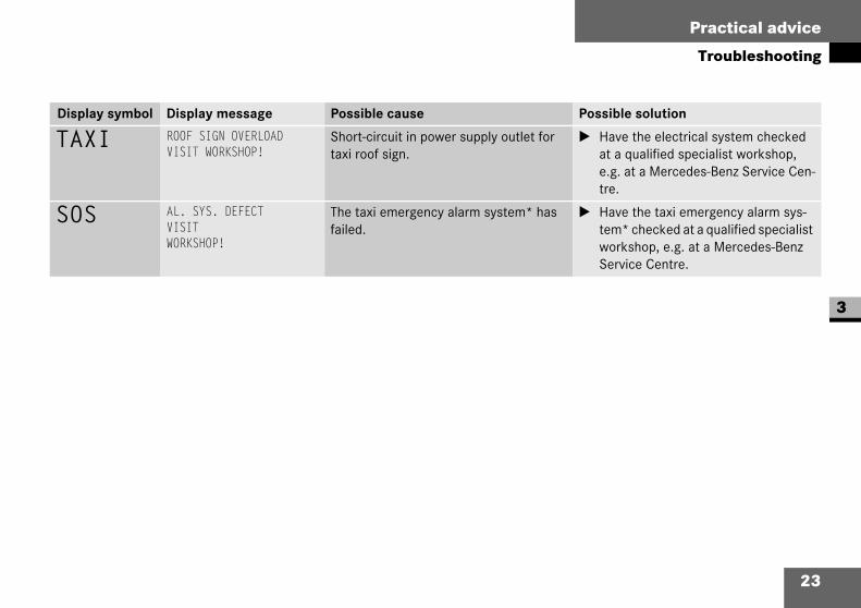
Display symbol Display message Possible cause Possible solution
– UNDERVOLTAGEENGINE ON
The vehicle battery voltage has fallen below 11.2 volts while the engine was switched off.
Switch off all electrical consumers which are not required. Start the engine as described in the "Getting started" section in the vehicle Owner's Manual.
Note that after this warning message appears, the following consumers could be switched off:
Roof sign illumination
Two-way radio power supply
Separate 12 volt power supply con-nection for taximeter peripherals
The taximeter is not switched off when undervoltage is indicated.

22
Practical advice
Troubleshooting
3
Display symbol Display message Possible cause Possible solution
TAXI ROOF SIGNCHECKROOF SIGN!
The taxi roof sign may not be connected. Plug in the connector ( page 37).
ROOF SIGNCHECK LAMP!
One or more lamps are defective. Change the lamps.
TAXI ELECTRICS DEFECTVISITWORKSHOP!
Short-circuit in at least one power supply outlet for:
Two-way radio connection in the upper or lower section of the centre console*
Taximeter connection in the overhead control panel or in the lower section of the centre console*
Separate 12 volt power supply con-nection for taximeter peripherals
The taxi-specific electrics have failed.
Have the electrical system checked at a qualified specialist workshop, e.g. at a Mercedes-Benz Service Cen-tre.
23
Practical advice
Troubleshooting
3
Display symbol Display message Possible cause Possible solution
TAXI ROOF SIGN OVERLOADVISIT WORKSHOP!
Short-circuit in power supply outlet for taxi roof sign.
Have the electrical system checked at a qualified specialist workshop, e.g. at a Mercedes-Benz Service Cen-tre.
SOS AL. SYS. DEFECTVISITWORKSHOP!
The taxi emergency alarm system* has failed.
Have the taxi emergency alarm sys-tem* checked at a qualified specialist workshop, e.g. at a Mercedes-Benz Service Centre.

24
Practical advice
Changing the batteries
3
When the radio remote control batteries (2 x 3 volts, 10 mAh) are discharged, you can no longer trigger the taxi emergency alarm from a distance.
iSuitable batteries are available from a qualified specialist workshop, e.g. a Mercedes-Benz Service Centre.
You can also have the batteries changed there and return the old bat-teries. In many EU countries and in other countries, vendors are obliged to take back old batteries.
Risk of poisoning G
Batteries contain poisonous and caustic substances. For this reason, keep batteries away from children.
If a battery is swallowed, consult a doctor immediately.
Environmental note H
Do not dispose of batteries with the house-hold rubbish.They contain poisonous substances.
Return discharged batteries to a qualified specialist workshop, e.g. a Mercedes-Benz Service Centre or a special collection point for old batteries.
Changing the radio remote control batteries
Risk of explosion G
There is a risk of explosion if you
change batteries incorrectly
try to recharge the batteries
burn the batteries
try to open the batteries with force
For this reason, observe the following instructions. Only replace the batteries in pairs and use batteries of the same specifi-cation as those recommended by the manu-facturer.

25
Practical advice
Changing the batteries
3
Open cover 1 by turning it with a coin in the direction of arrow 2. 1 Cover
2 To open3 To close
Remove the old batteries.
Insert new batteries 4 in the radio remote control with the positive sign facing upwards.
1 Cover4 Batteries
Place cover 1 on the radio remote control.
Close cover 1 by turning it as far as the stop in the direction of arrow 3.
!Do not operate the remote control when changing the batteries.
Do not touch the contact surfaces of the batteries. Only touch the batteries with a clean, lint-free cloth or similar. Do not work with wet or greasy fingers.
26
Practical advice
Fuses
3
The entire taxi-specific electronics and the separate 12 volt power supply connection ( page 35) are protected by the PSM module.
The two fuses (25 A) for the PSM module are located in the fuse box in the driver's seat.
You will find information on the fuse box in the driver's seat in the "Practical advice" section of the vehicle Owner's Manual.

27
Practical advice
Installing the taximeter
3
Installing the taximeter
1 Torx screws2 Installation space3 Lower section of the centre console
Unscrew the four Torx screws 1 on both sides of lower section of the cen-tre console 3.
Remove lower section of the centre console 3 to the rear. Take care not to damage the two-way radio loudspeaker in the front-passenger footwell when doing this ( page 15).
Secure the DIN-compliant adapter of the taximeter/two-way radio in instal-lation space 2.
4 Taximeter connection cable5 Two-way radio connection cable
Risk of injury G
You could injure yourself on sharp-edged frame parts or reinforcement materials dur-ing installation. For this reason, have the taximeter installed at a qualified specialist workshop, e.g. at a Mercedes-Benz Service Centre.
!Before installing the taximeter, you must connect the quiescent current retention unit and disconnect the bat-tery earthing line.
iThe equipment bracket in the lower section of the centre console* is designed to hold taximeters and two-way radios with DIN-compliant adapter.
Installing a taximeter in the lower section of the centre console*

28
Practical advice
Installing the taximeter
3
Guide taximeter connection cable 4 into installation space 2 on lower sec-tion of the centre console 3.
Connect the taximeter/two-way radio in accordance with the manufacturer's wiring diagram.
Pin assignment for taximeter connec-tor ( page 41).
Pin assignment for two-way radio con-nector ( page 40) and aerial ( page 39).
Press the taximeter/two-way radio into the installation aid and make sure it is firmly seated.
Refit lower section of the centre console 3. Take care not to damage the two-way radio loudspeaker in the front-passenger footwell ( page 15) and the routing of the connection cables under the console.
Reconnect the battery.
Disconnect the quiescent current retention unit.
Carry out a function check on the taximeter/two-way radio.
Two-way radio operation ( page 18)
iTo install a two-way radio in the lower section of the centre console, guide two-way radio connection cables 5 into installation space 2.
iInformation and documents about cali-brating the taximeter can be obtained from any Mercedes-Benz Service Cen-tre.
29
Practical advice
Installing the taximeter
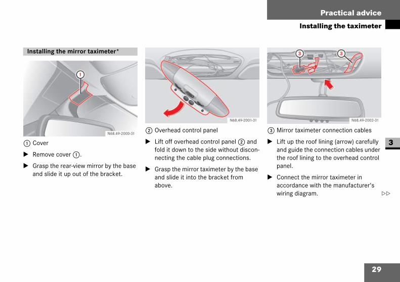
31 Cover
Remove cover 1.
Grasp the rear-view mirror by the base and slide it up out of the bracket.
2 Overhead control panel
Lift off overhead control panel 2 and fold it down to the side without discon-necting the cable plug connections.
Grasp the mirror taximeter by the base and slide it into the bracket from above.
3 Mirror taximeter connection cables
Lift up the roof lining (arrow) carefully and guide the connection cables under the roof lining to the overhead control panel.
Connect the mirror taximeter in accordance with the manufacturer's wiring diagram.
Installing the mirror taximeter*
30
Practical advice
Installing the taximeter
3
Install the connecting cables in such a manner that they cannot move about. Secure them in place with foam mate-rial if necessary.
Pin assignment for mirror taximeter connector ( page 42).
Replace cover 1.
Refit overhead control panel 2. When doing so, take care not to trap any cables.
Reconnect the battery.
Disconnect the quiescent current retention unit.
Carry out a function check on the mir-ror taximeter.
After you have installed the mirror taxi-meter, you must have it initialised at a qualified specialist workshop, e.g. a Mercedes-Benz Service Centre.

31
Practical advice
Installing the two-way radio
3
Installing the two-way radio
The two-way radio is installed in the lower section of the centre console in the same way as the taximeter and is described in the section entitled "Installing a taximeter in the lower section of the centre con-sole*" ( page 27).
Risk of injury G
You could injure yourself on sharp-edged frame parts or reinforcement materials dur-ing installation.
For this reason, have the two-way radio installed at a qualified specialist workshop, e.g. at a Mercedes-Benz Service Centre.
!Before installing the two-way radio, you must connect the quiescent current retention unit and disconnect the bat-tery earthing line.
iThe equipment bracket in the lower section of the centre console* is designed for holding taximeters and two-way radios with DIN-compliant adapter.
Installing a two-way radio in the lower section of the centre console*

32
Practical advice
Installing the two-way radio
31 Trim2 Two-way radio mounting frame trim3 Ashtray4 Cigarette lighter5 Torx screws6 Lower section of the centre console*7 Gear lever cover
Remove trim 1 from the centre con-sole.
Remove trim 2 from the radio mount-ing frame.
Unscrew the four Torx screws 5 on both sides of lower section of the cen-tre console* 6 or the footwell trim.
Remove lower section of the centre console* 6 or the footwell trim to the rear. Take care not to damage the two-way radio loudspeaker in the front-pas-senger footwell when doing this ( page 15).
Pull out cigarette lighter 4.
Pull out the ashtray insert and remove ashtray 3. Take care not to damage the ashtray light when doing this.
You will find information on the ashtray in the "Controls in detail" section of the vehicle Owner's Manual.
Pull the back of the bulb holder out of the ashtray housing.
Lift gear lever cover 7 away from gear lever trim 9 in an upwards direction.
Installing the two-way radio in the centre console

33
Practical advice
Installing the two-way radio
3
8 Torx screws9 Trima Two-way radio connection cable
Unscrew the seven Torx screws 8 from trim 9
Fit trim 9 over the gear lever and link-age. Take care not to damage the bulb holder in the ashtray light and the ciga-rette lighter connection cable when doing this.
b Torx screwsc Two-way radio mounting frame
Unscrew both Torx screws b from two-way radio mounting frame c.
Remove two-way radio mounting frame c from the installation space.
Secure the two-way radio using either a DIN-compliant adapter or a screw con-nection on two-way radio mounting frame c.
iIf no radio is fitted in the centre con-sole, you must remove a double mount-ing frame. This is secured by four screws.

34
Practical advice
Installing the two-way radio
3
Guide two-way radio connection cables a through the centre console upwards into the two-way radio installation space.
Connect the two-way radio in accord-ance with the manufacturer's wiring diagram.
Pin assignment for two-way radio con-nector ( page 40) and aerial ( page 39).
Press two-way radio mounting frame c with the two-way radio into the installation space.
Tighten Torx screws b on two-way radio mounting frame c or the double mounting frame.
Fit trim 1 on the centre console. Make sure that the clamps on the trim engage.
Refit trim 9. Take care not to damage the bulb holder in the ashtray light and the cigarette lighter connection cable when doing this.
Insert the bulb holder for the ashtray light into the ashtray housing.
Refit ashtray 3 and the insert in the centre console.
Re-insert cigarette lighter 4 in its socket.
Replace gear lever cover 7 on trim 9.
Refit lower section of the centre con-sole* 6 or the footwell trim. Take care not to damage the two-way radio loud-speaker in the front-passenger footwell when doing this ( page 15).
Reconnect the battery.
Disconnect the quiescent current retention unit.
Carry out a function check on the two-way radio.
Two-way radio operation ( page 18)
iTie back the connection cables and connector in the lower area of the cen-tre console ( page 33).

35
Practical advice
Connecting peripherals
3
Connecting peripherals
You can use a 12 volt power supply con-nection for accessories up to a maximum of 100 W.
The tied-back connectors for the taximeter peripherals, the separate 12 volt power supply and the HALE CEY system are located in the lower section of the centre console* or in the footwell trim.
1 Torx screws2 Lower section of centre console*
Unscrew the four Torx screws 1 from both sides of the lower section of cen-tre console*2 or the footwell trim.
Risk of injury G
You could injure yourself on sharp-edged frame parts or reinforcement materials dur-ing installation.
For this reason, have the peripherals installed at a qualified specialist workshop, e.g. a Mercedes-Benz Service Centre.
!Before installing a device, you must connect the quiescent current reten-tion unit and disconnect the battery earthing line.
iThe 12 volt power supply connection is only supplied with power by the battery when the key is in position 1 or 2. The connection is protected by the PSM module.
If the vehicle battery voltage falls below 11.2 V, the 12 volt power supply con-nection switches off.

36
Practical advice
Connecting peripherals
3
Remove lower section of the centre console* 2 or the footwell trim to the rear. Take care not to damage the two-way radio loudspeaker in the front-pas-senger footwell when doing this ( page 15).
3 Connection cable for taximeter periph-erals
4 HALE CEY system connection cable5 12 volt power supply connection cable
Connect the device in accordance with the manufacturer's wiring diagram.
Pin assignment for peripherals, sepa-rate 12 volt power supply and HALE CEY system ( page 43)
Refit lower section of centre console* 2 or the footwell trim. Take care not to damage the two-way radio loud-speaker in the front-passenger footwell ( page 15) and the routing of the con-nection cables under the console or trim.
Reconnect the battery.
Disconnect the quiescent current retention unit.
Carry out a function check on the device.
37
Practical advice
Fitting the taxi roof sign
3
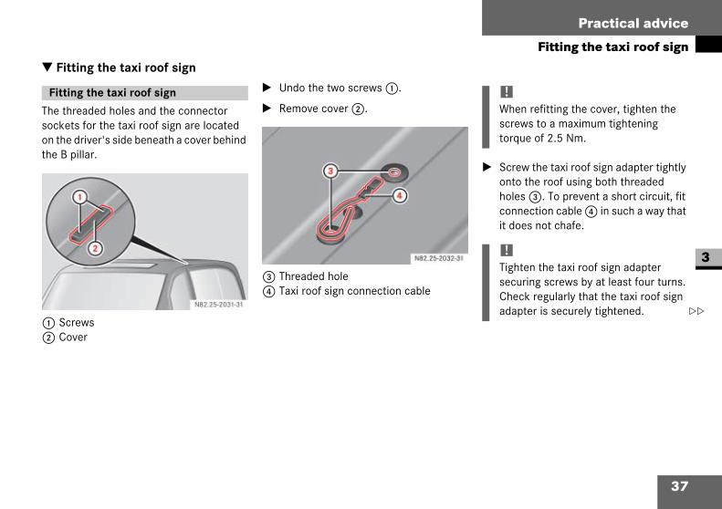
Fitting the taxi roof sign
The threaded holes and the connector sockets for the taxi roof sign are located on the driver's side beneath a cover behind the B pillar.
1 Screws2 Cover
Undo the two screws 1.
Remove cover 2.
3 Threaded hole4 Taxi roof sign connection cable
Screw the taxi roof sign adapter tightly onto the roof using both threaded holes 3. To prevent a short circuit, fit connection cable 4 in such a way that it does not chafe.
Fitting the taxi roof sign !When refitting the cover, tighten the screws to a maximum tightening torque of 2.5 Nm.
!Tighten the taxi roof sign adapter securing screws by at least four turns.Check regularly that the taxi roof sign adapter is securely tightened.

38
Practical advice
Fitting the taxi roof sign
3
Remove connector cap from connec-tion cable 4.
Connect the taxi roof sign to connec-tion cable 4.
Connector socket assignment for taxi roof sign illumination ( page 39)
iThe taxi roof sign adapters are not included in the Mercedes-Benz scope of delivery. These adapters can be obtained from suppliers of taxi-specific accessories.
iThe connector for the taxi roof sign is included with the vehicle documenta-tion.
iThe connector socket for the taxi roof sign illumination can carry a maximum load of 5 A.
!The taxi roof sign may become dam-aged if the vehicle is washed in an auto-matic car wash. You should remove the roof sign before using an automatic car wash.

39
Practical advice
Connectors
3
Connectors
The connector socket for the roof sign is located under the cover on the roof ( page 37).
The tied-back aerial connector is located in the lower section of the centre console* or in the footwell trim.
1 Aerial (signal)2 Aerial (earth)
Connector socket for taxi roof sign Pin Assignment
1 Earth (terminal 31, black)
2 Power supply(terminal 30, white)
Maximum load: 5 A
iThe connector for the roof sign is included with the vehicle documenta-tion.
Order numbers ( page 48)
Connector for two-way radio aerial

40
Practical advice
Connectors
3
The tied-back connector for the two-way radio is located in the lower section of the centre console* or in the footwell trim.
Connector for two-way radio Pin Assignment
1 Loudspeaker (earth)
2 Loudspeaker (signal)
3 Microphone (signal)
4 Microphone (earth)
5 Two-way radio actuation
6 Earth for triggered taxi emer-gency alarm system*
7 Power supply (terminal 30)
Maximum load: 5 A
8 Earth (terminal 31)
iThe coupling for the two-way radio con-nection, the power supply and the elec-trical connection components can be found with the vehicle documentation. They can also be obtained from any Mercedes-Benz Service Centre.
Order numbers ( page 48)
41
Practical advice
Connectors
3
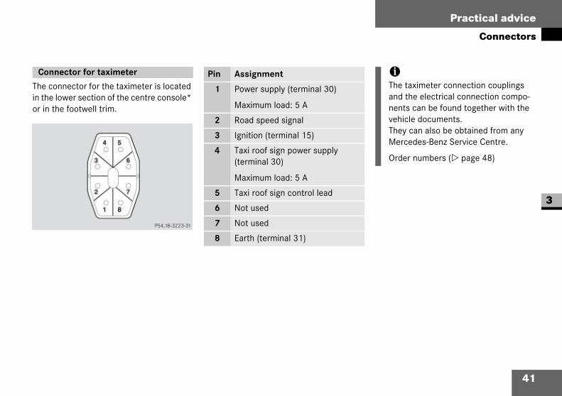
The connector for the taximeter is located in the lower section of the centre console* or in the footwell trim.
Connector for taximeter Pin Assignment
1 Power supply (terminal 30)
Maximum load: 5 A
2 Road speed signal
3 Ignition (terminal 15)
4 Taxi roof sign power supply (terminal 30)
Maximum load: 5 A
5 Taxi roof sign control lead
6 Not used
7 Not used
8 Earth (terminal 31)
iThe taximeter connection couplings and the electrical connection compo-nents can be found together with the vehicle documents.They can also be obtained from any Mercedes-Benz Service Centre.
Order numbers ( page 48)

42
Practical advice
Connectors
3
The mirror taximeter connectors are secured under the overhead control panel.
1 Connector for taximeter functions2 CAN system connector (white)3 Connector for display control
Connector 1: Connector 2:
Connector 3:
Retrofitting a mirror taximeter* ( page 29)
Connectors for mirror taximeterPin Assignment
1 Power supply (terminal 30)
Maximum load: 5 A
2 Earth (terminal 31)
3 Not used
4 RS 485 A+ (data)
5 RS 485 B– (inv.)
6 Key ground (Hale)
7 Key data (Hale)
8 Not used
9 Not used
10 Not used
Pin Assignment
1 CAN peripherals (high)
2 CAN peripherals (low)
Pin Assignment
1 Ignition (terminal 15)
2 Pulse out
3 Earth (terminal 31)

43
Practical advice
Connectors
3
The connectors for the taximeter peripher-als, the separate 12 volt power supply and the HALE CEY system are secured in the lower section of the centre console* or in the footwell trim.
1 Connector for taximeter peripherals2 HALE CEY system connector3 12 volt power supply connector
Connector 1: Connector 2:
Connector 3:
Connectors for peripherals and HALE CEY system Pin Assignment
1 Not used
2 Not used
3 Not used
4 Not used
5 CAN-Hale (high)
6 CAN-Hale (low)
7 Power supply (terminal 30)
Maximum load: 5 A
8 Earth (terminal 31)
9 Not used
10 Not used
Pin Assignment
1 Data
2 Ground
Pin Assignment
1 Power supply (terminal 30)
Maximum load: 10 A
2 Earth (terminal 31)
iThe electrical connection components can be found together with the vehicle documents. They can also be obtained from any Mercedes-Benz Service Cen-tre.
Order numbers ( page 48)

44
Practical advice
Roof aerial
3
1 To fit aerial rod2 To remove aerial rod
Removing aerial rod
Turn the aerial rod anti-clockwise 2.
Fitting aerial rod
Turn the aerial rod clockwise 1.
The aerial rod must be tuned to the trans-mitter frequency of the two-way radio before it is used for the first time.
!The roof aerial (D/E networks, GPS reception and radio in the 2 m or 70 cm waveband) may become damaged if the vehicle is washed in an automatic car wash. You must remove the aerial rod before using an automatic car wash.
Tuning the aerial rod to the transmitter frequency
!Have the low-reflection tuning of the aerial rod to the transmitter frequency carried out at a qualified specialist workshop.
iA diagram for tuning the aerial to the transmitter frequency is enclosed with the vehicle documentation.Select an average length for the aerial rod if you wish to transmit on more than one frequency.

45
Practical advice
Roof aerial
3
1 Tip protection2 Aerial housing3 Screws
Remove tip protection 1 from the aer-ial rod.
Shorten the aerial rod according to the diagram provided.
Remove 10 mm of the heat-shrinkable sleeve on the aerial rod tip.
Replace the tip protection on the aerial rod.
Screw the aerial rod into aerial housing 2.
Check the tuning of the aerial outside with the vehicle doors closed using an SWR power meter.
You can remove aerial housing 2 if you wish to attach adhesive film to the vehicle.
Unscrew screw 3.
Remove aerial housing 2 upwards.
Proceed in the reverse order to refit aerial housing 2.
iEven more precise tuning is possible using an SWR power meter.
Removing and refitting the aerial housing
!When replacing aerial housing 2, make sure that the contact spring on the printed circuit board is not bent.
Retighten securing screw 3 to a max-imum torque of 0.2 +0.1 Nm.

46

47
4
Technical data
Order numbers
Road speed signal
Electret microphone

48
Technical data
Order numbers
4
Electrical connection components and a complete set of connectors and pins (Order number for set: 203 820 0237) are available from a Mercedes-Benz Service Centre.
iA complete set of connectors and pins is supplied with every taxi when deliv-ered from the factory.
Order numbers for electrical connection components
Taximeter connector
1 Connector housing: 017 545 5728
2 Internal connector part:
000 545 3540
3 Pin (connector pin): 017 545 6328
Taximeter coupling
1 Coupling housing: 017 545 5628
2 Internal coupling part: 000 545 3540
3 Coupling socket pin: 003 545 4826

49
Technical data
Order numbers
4
Two-way radio connector
1 Connector: 030 545 3628
2 Connector housing pin:
018 545 1928
3 Coupling: 030 545 3528
4 Coupling housing pin (2.5 mm2):
003 545 5226
Coupling housing pin (0.75 mm2):
003 545 5126
Coupling housing pin (0.35 mm2):
005 545 1826
Peripherals connector
1 Connector housing: 168 545 4328
2 Connector housing pin:
026 545 8328
HALE CEY system connector
1 Connector housing: 033 545 6728
2 Connector housing pin:
026 545 8328
12 volt power supply connector
1 Connector housing: 037 545 1128
2 Connector housing pin:
010 545 9526
Roof sign coupling
1 Coupling: 046 545 6828
2 Coupling housing pin:
015 545 2026
50
Technical data
Road speed signal
4
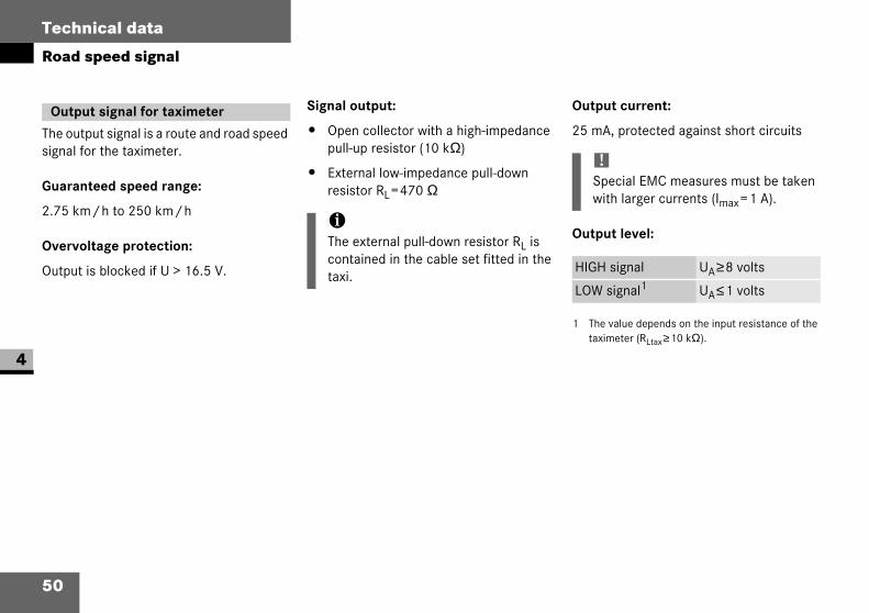
The output signal is a route and road speed signal for the taximeter.
Guaranteed speed range:
2.75 km/h to 250 km/h
Overvoltage protection:
Output is blocked if U > 16.5 V.
Signal output:
Open collector with a high-impedance pull-up resistor (10 kΩ)
External low-impedance pull-downresistor RL=470 Ω
Output current:
25 mA, protected against short circuits
Output level:
Output signal for taximeter
iThe external pull-down resistor RL is contained in the cable set fitted in the taxi.
!Special EMC measures must be taken with larger currents (Imax=1 A).
HIGH signal UA≥8 volts
LOW signal1
1 The value depends on the input resistance of the taximeter (RLtax≥10 kΩ).
UA≤1 volts

51
Technical data
Road speed signal
4
The illustrated circuit diagram shows the recommended wiring for the road speed signal output.
Signal form:
Square wave
Pulse sequence:
4 pulses per metre (pulse width =4 ms)
The pulse duration is the same as the pulse pause above a speed of 69.9 mph (112.5 km/h) (1:1 pulse duty factor).
The ratio is maintained at higher speeds. The pulse duration and pause both become shorter.i
The data below refers to wheels with a dynamic rolling radius of 0.33 m.

52
Technical data
Electret microphone
4
The illustrated circuit diagram (example) shows you how the electret microphone is adapted to a two-way radio.
For example:
Decoupling capacitor C=10 µF
Coupling resistance RL = 680 Ω (if UB = 8 V and Imax = 6 mA)
To calculate coupling resistance RL for other supply voltages:
RL=UB/Imax (with Imax=6 mA)
For UB you must refer to the technical data for your two-way radio.
Coupling electronics
!Have the coupling electronics for con-necting an electret microphone to a two-way radio prepared by authorised radio installation specialists.

53
Technical data
Electret microphone
4
1 Guidelines; the level depends greatly on the speech patterns of the individual and background noise.
Technical data
Microphone model AKG/Q 400 MK II T
Operating temperature –25°C to +70 °C
Transmission range 300 Hz to 6,500 Hz
Directional characteristic unidirectional
Impedance < 100 ΩMicrophone operating voltage UDC = 4.0 VDC ±0.2 V
Current draw
(if UB = 8 VDC and RL = 680 Ω)
Imax=6 mA ±0.4 mA
Sensitivity
(0 dB = 10 V/Pa; f = 1 kHz)
600 mV/Pa
Microphone level with normal background noise1 Voice level Voice signal
Normal 70 dB SPL 50 mV
Maximum 90 dB SPL 400 mV

54

55
Technical terms
5
Technical termse mark
Symbol to indicate certification in ac-cordance with the relevant EU Direc-tives.
EMC(ElectroMagnetic Compatibility)The electrical and electronic compo-nents of the vehicle are protected from interference fields, e.g. transmitters, radar systems, current conductors or radiophones.
GPS(Global Positioning System)Satellite signals supply information about the geographical location of the vehicle via suitable receivers. These signals can be compared with a digital map (e.g. on CD ROM) and may be used to determine the location of the vehicle and for navigation purposes.
HALE CEY system(Driver cashing up system)This system is used to download data from the trip meter/taximeter to a PC. This enables shift data to be analysed.
PSM(Programmable Special ModuleThe module provides a defined inter-face for vehicle data, parameters and power supply to equipment parts.

56

57
5
Index
AAerial
Aerial rod . . . . . . . . . . . . . . . . . . . . . 44Connector . . . . . . . . . . . . . . . . . . . . . 39Removing and refitting the housing . 45Tuning to the transmitter frequency . 44
CCockpit . . . . . . . . . . . . . . . . . . . . . . . . 10Connector
Aerial. . . . . . . . . . . . . . . . . . . . . . . . . 39HALE CEY system . . . . . . . . . . . . . . . 43Mirror taximeter* . . . . . . . . . . . . . . . 42Taxi roof sign illumination. . . . . . . . . 38Taximeter . . . . . . . . . . . . . . . . . . . . . 41Taximeter peripherals . . . . . . . . . . . . 43Two-way radio. . . . . . . . . . . . . . . . . . 4012 volt power supply . . . . . . . . . . . . 43
Connector socketTaxi roof sign . . . . . . . . . . . . . . . . . . 39
Coupling electronicsElectret microphone . . . . . . . . . . . . . 52
DDisplay messages*
Battery/undervoltage . . . . . . . . . . . . 21TAXI. . . . . . . . . . . . . . . . . . . . . . . . . . 22Taxi roof sign illumination on . . . . . . 17
Ee mark . . . . . . . . . . . . . . . . . . . . . . . 5, 55Electret microphone . . . . . . . . . . . . . 15
Coupling electronics . . . . . . . . . . . . . 52Technical data. . . . . . . . . . . . . . . . . . 53
Electrical and electronic equipmentRetrofitting . . . . . . . . . . . . . . . . . . . . . 5
Electrical connection componentsOrder numbers . . . . . . . . . . . . . . . . . 48
EMC . . . . . . . . . . . . . . . . . . . . . . . . . . . 55
FFault messages
see Display messages*Fax machine
Installation . . . . . . . . . . . . . . . . . . . . . 5Operation . . . . . . . . . . . . . . . . . . . . . . 7
FrequenciesAerial comparison . . . . . . . . . . . . . . . 44Telephone/two-way radio . . . . . . . . . . 6
Fuses . . . . . . . . . . . . . . . . . . . . . . . . . . 26
GGPS . . . . . . . . . . . . . . . . . . . . . . . . . . . 55
HHALE CEY system. . . . . . . . . . . . . . . . 55
Connecting . . . . . . . . . . . . . . . . . . . . 35Connectors . . . . . . . . . . . . . . . . . 42, 43
IInstallation
Electrical and electronic equipment . . 5
MMalfunction messages
see Display messages*Microphone
see Electret microphoneMirror taximeter*
Connectors . . . . . . . . . . . . . . . . . . . . 42Installing . . . . . . . . . . . . . . . . . . . . . . 29

58
Index
5
Mobile phonesee Telephone
OOperating safety . . . . . . . . . . . . . . . . . 5Operation
Fax machine . . . . . . . . . . . . . . . . . . . . 7Mobile phone . . . . . . . . . . . . . . . . . . . 7Two-way radio . . . . . . . . . . . . . . . . 7, 18
Order numbers for electrical connection components . . . . . . . . . . 48
PPeripherals
Connecting . . . . . . . . . . . . . . . . . . . . 35Connectors . . . . . . . . . . . . . . . . . . . . 43Installation . . . . . . . . . . . . . . . . . . . . . 5
Power supply, 12 voltConnecting . . . . . . . . . . . . . . . . . . . . 35Connectors . . . . . . . . . . . . . . . . . . . . 43
PSM . . . . . . . . . . . . . . . . . . . . . . . . . . . 55
RRadio remote control
BatteriesChanging . . . . . . . . . . . . . . . . . . . . 24
Radio remote control batteriesChanging . . . . . . . . . . . . . . . . . . . . . . 24
RetrofittingElectrical and electronic equipment . . 5
Roof aerialsee Aerial
Roof signsee Taxi roof sign
SSpeed signal
Taximeter . . . . . . . . . . . . . . . . . . . . . 50
TTaxi roof sign
Fault message . . . . . . . . . . . . . . . . . . 22Fitting . . . . . . . . . . . . . . . . . . . . . . . . 37
Illumination . . . . . . . . . . . . . . . . . . . . 16Activating power supply. . . . . . . . . 17Switching off . . . . . . . . . . . . . . . . . 17
Indicator in the display* . . . . . . . . . . 17Pushbutton switch. . . . . . . . . . . . . . . 16
TaximeterConnector . . . . . . . . . . . . . . . . . . . . . 41Installation. . . . . . . . . . . . . . . . . . . . . . 5
In the lower section of the centre console* . . . . . . . . . . . . . . . . . . . . 27
Mirror taximeter*Connector . . . . . . . . . . . . . . . . . . . 42Installing . . . . . . . . . . . . . . . . . . . . 29
PeripheralsConnecting. . . . . . . . . . . . . . . . . . . 35Connectors . . . . . . . . . . . . . . . . . . 43
Speed signal . . . . . . . . . . . . . . . . . . . 50Telephone
Frequencies. . . . . . . . . . . . . . . . . . . . . 6Installation. . . . . . . . . . . . . . . . . . . . . . 5Operation . . . . . . . . . . . . . . . . . . . . . . 7

59
Index
5
Transmission outputTwo-way radio. . . . . . . . . . . . . . . . . . . 6
Two-way radioConnector . . . . . . . . . . . . . . . . . . . . . 40Connector, aerial . . . . . . . . . . . . . . . 39Frequencies . . . . . . . . . . . . . . . . . . . . 6Hands-free facility. . . . . . . . . . . . . . . 14Installation . . . . . . . . . . . . . . . . . . . . . 5
In the centre console. . . . . . . . . . . 32In the lower section of the centre console* . . . . . . . . . . . . . . . . . 27, 31
Noise suppressor . . . . . . . . . . . . . . . 18Operation . . . . . . . . . . . . . . . . . . . 7, 18Receiving . . . . . . . . . . . . . . . . . . . . . 14Transmission output . . . . . . . . . . . . . . 6Transmitter button . . . . . . . . . . . . . . 14
Two-way radio loudspeaker . . . . . . . 15Two-way radio with hands-free facility . . . . . . . . . . . . . . . . . . . . . . . . . 14
Electret microphone . . . . . . . . . . . . . 15Coupling electronics . . . . . . . . . . . 52Technical data . . . . . . . . . . . . . . . . 53
Receiving . . . . . . . . . . . . . . . . . . . . . 14Speaking . . . . . . . . . . . . . . . . . . . . . . 14Two-way radio loudspeaker . . . . . . . 15
WWarning messages
see Display messages*

Thank you for choosing a Mercedes-Benz vehicle with special taxi equipment.
Before you operate the taxi-specific equip-ment and systems, familiarise yourself with your taxi's special equipment and read this supplement. This will help you to obtain the maximum pleasure from your vehicle and to avoid endangering yourself and others.
Items of special equipment are marked with an asterisk *.
The taxi-specific equipment in your vehicle may vary, depending on the model, the country specifications and availability.
Mercedes-Benz is constantly updating its vehicles to the state of the art and there-fore reserves the right to introduce chang-es in design, equipment and technical features at any time. Claims based on the data, illustrations or descriptions in this supplement cannot, therefore, be enter-tained.
The nearest Mercedes-Benz Service Cen-tre will be happy to help should you have any questions.
This supplement is an integral part of your vehicle. You should always keep it in the vehicle and pass it on to the new owner if you sell the vehicle.
The technical documentation team at Mercedes-Benz wishes you safe and pleas-ant motoring.
Risk of injury G
This supplement in no way replaces the de-tailed Owner's Manual. This is especially im-portant with regard to warning notes. Before you drive off, please read with the detailed Owner's Manual, particularly the "Safety" section.
You may otherwise fail to recognise dangers and injure yourself or others.
Contact
Mercedes-Benz will be happy to answer any questions you may have:
Mercedes-Benz Contact Telephone: 00800 1 777 7777International: +49 69 95 30 72 77
Internet
Further information about Mercedes-Benz vehicles and DaimlerChrysler can be found on the following websites:
www.mercedes-benz.comwww.daimlerchrysler.com
Editorial office
You are welcome to forward any queries or suggestions you might have about this supplement to the technical documentation team at the following address:
DaimlerChrysler AG, HPC: R803, 70546 Stuttgart, Germany
As at: 20.03.2003
Title illustration: P00.01-2254-31
Not to be reprinted, translated or otherwise reproduced, in whole or in part, without written permission.