Bike, Scooter, and Chopper Projects for the Evil Genius
314
-
Upload
kathy-mcgowan -
Category
Documents
-
view
226 -
download
5
Transcript of Bike, Scooter, and Chopper Projects for the Evil Genius


Bike, Scooter, andChopper Projects for
the Evil Genius

Evil Genius Series
Bike, Scooter, and Chopper Projects for the Evil Genius
Bionics for the Evil Genius: 25 Build-It-Yourself Projects
Electronic Circuits for the Evil Genius: 57 Lessons with Projects
Electronic Gadgets for the Evil Genius: 28 Build-It-Yourself Projects
Electronic Games for the Evil Genius
Electronic Sensors for the Evil Genius: 54 Electrifying Projects
50 Awesome Auto Projects for the Evil Genius
50 Model Rocket Projects for the Evil Genius
51 High-Tech Practical Jokes for the Evil Genius
Fuel Cell Projects for the Evil Genius
Mechatronics for the Evil Genius: 25 Build-It-Yourself Projects
MORE Electronic Gadgets for the Evil Genius: 40 NEW Build-It-Yourself Projects
101 Outer Space Projects for the Evil Genius
101 Spy Gadgets for the Evil Genius
123 PIC® Microcontroller Experiments for the Evil Genius
123 Robotics Experiments for the Evil Genius
PC Mods for the Evil Genius
Programming Video Games for the Evil Genius
Solar Energy Projects for the Evil Genius
22 Radio and Receiver Projects for the Evil Genius
25 Home Automation Projects for the Evil Genius

Bike, Scooter, andChopper Projects for
the Evil Genius
BRAD GRAHAMKATHY McGOWAN
New York Chicago San Francisco Lisbon London MadridMexico City Milan New Delhi San Juan Seoul
Singapore Sydney Toronto

Copyright © 2008 by The McGraw-Hill Companies, Inc. All rights reserved. Manufactured in the United States of America. Except as permitted underthe United States Copyright Act of 1976, no part of this publication may be reproduced or distributed in any form or by any means, or stored in a database or retrieval system, without the prior written permission of the publisher.
0-07-164355-9
The material in this eBook also appears in the print version of this title: 0-07-154526-3.
All trademarks are trademarks of their respective owners. Rather than put a trademark symbol after every occurrence of a trademarked name, we usenames in an editorial fashion only, and to the benefit of the trademark owner, with no intention of infringement of the trademark. Where such designations appear in this book, they have been printed with initial caps.
McGraw-Hill eBooks are available at special quantity discounts to use as premiums and sales promotions, or for use in corporate training programs.For more information, please contact George Hoare, Special Sales, at [email protected] or (212) 904-4069.
TERMS OF USE
This is a copyrighted work and The McGraw-Hill Companies, Inc. (“McGraw-Hill”) and its licensors reserve all rights in and to the work. Use of thiswork is subject to these terms. Except as permitted under the Copyright Act of 1976 and the right to store and retrieve one copy of the work, you maynot decompile, disassemble, reverse engineer, reproduce, modify, create derivative works based upon, transmit, distribute, disseminate, sell, publish orsublicense the work or any part of it without McGraw-Hill’s prior consent. You may use the work for your own noncommercial and personal use; anyother use of the work is strictly prohibited. Your right to use the work may be terminated if you fail to comply with these terms.
THE WORK IS PROVIDED “AS IS.” McGRAW-HILL AND ITS LICENSORS MAKE NO GUARANTEES OR WARRANTIES AS TO THE ACCURACY, ADEQUACY OR COMPLETENESS OF OR RESULTS TO BE OBTAINED FROM USING THE WORK, INCLUDING ANY INFORMATION THAT CAN BE ACCESSED THROUGH THE WORK VIA HYPERLINK OR OTHERWISE, AND EXPRESSLY DISCLAIM ANYWARRANTY, EXPRESS OR IMPLIED, INCLUDING BUT NOT LIMITED TO IMPLIED WARRANTIES OF MERCHANTABILITY OR FITNESSFOR A PARTICULAR PURPOSE. McGraw-Hill and its licensors do not warrant or guarantee that the functions contained in the work will meet yourrequirements or that its operation will be uninterrupted or error free. Neither McGraw-Hill nor its licensors shall be liable to you or anyone else for anyinaccuracy, error or omission, regardless of cause, in the work or for any damages resulting therefrom. McGraw-Hill has no responsibility for the content of any information accessed through the work. Under no circumstances shall McGraw-Hill and/or its licensors be liable for any indirect, incidental, special, punitive, consequential or similar damages that result from the use of or inability to use the work, even if any of them has beenadvised of the possibility of such damages. This limitation of liability shall apply to any claim or cause whatsoever whether such claim or cause arises in contract, tort or otherwise.
DOI: 10.1036/0071545263

We hope you enjoy thisMcGraw-Hill eBook! If
you’d like more information about this book,its author, or related books and websites,please click here.
Professional
Want to learn more?

About the Authors
Brad Graham is an inventor, robotics hobbyist, founder
and host of the atomiczombie.com website. He is the
coauthor of 51 High Tech Practical Jokes for the Evil
Genius, 101 Spy Gadgets for the Evil Genius, Atomic
Zombie’s Bicycle Builder’s Bonanza—perhaps the most
creative bicycle-building guide ever written—and
Build Your Own All-Terrain Robot, from
McGraw-Hill Professional.
Kathy McGowan is Mr. Graham’s other “Evil
Genius” half, providing administrative, logistical and
marketing support for Atomic Zombie’s many robotics,
bicycle, technical, and publishing projects. She also
manages the daily operations of their high-tech firm and
several websites, including www.atomiczombie.com
vCopyright © 2008 by The McGraw-Hill Companies, Inc. Click here for terms of use.

This page intentionally left blank

Contents
Preface ixAcknowledgments xi
Section One Getting Started 1Project 1 A Complete Bicycle Autopsy 1
Section Two Attitude and Style 15Project 2 The Gladiator Chopper 16
Project 3 Old Skool Attitude 51
Project 4 Whippersnapper 57
SectionThree Speed and Comfort 61Project 5 StreetFox Tadpole Trike 62
Project 6 DeltaWolf Racing Trike 98
Project 7 Little Warrior Trike 146
Section Four Wild and Crazy Wheels 155Project 8 SpinCycle Stunt Trike 156
Project 9 UCan2 HandCycle 175
Project 10 SkyStyle Tallbike 200
Section Five Electric Power 207Project 11 Sparky Minibike 208
Project 12 LongRanger Scooter 242
Project 13 Silent Speedster 265
Project 14 Kids’ Electric Trike 286
Conclusion 293Index 295
vii
For more information about this title, click here

This page intentionally left blank

Preface
Greetings! Glad that you decided to take an interest in
the best hobby you will ever know! Maybe you are
already a seasoned garage hacker and have decided to
build a few of the projects from this book, adding your
own special modifications, of course. Or, maybe you
have never thought about taking an angle grinder to a
working bicycle, chopping it into 50 pieces so you can
twist and contort it into something unique and wonderful.
Well, dude, let me tell you, once you start building your
own custom vehicles, you will never stop. Some of your
neighbors will love what you do, visiting you often to see
what you are working on. Others will fear you like some
type of mad Evil Genius, and others will simply give you
that empty look that the dog often gives you when you
try to make him understand complex math. Now,
seriously, are you ready to be the “freak on the block,”
the dude who rides a pedal-powered chopper that looks
sicker than the one for sale at the Harley store? Are you
ready to beat your neighbors’ Hummer from one set of
lights to the next on a bicycle that weighs less than his
spare tire? Well, if this all sounds good, then you are like
me and are going to enjoy what you are about to read!
Nothing I build is impossible for anyone with a little
motivation. I own only an angle grinder, basic AC
welder, and the usual small hand tools. I have no lathe,
no drill press, no chop saw, and often have no heat in my
garage during the winter. I get most of my parts from the
city landfill site, and I have no degree on my wall that
says I am qualified for the engineering feats that I often
achieve. What I do have is the desire to hack, weld, and
ride! I have seen young garage hackers build great bikes
after only a week of owning a lunchbox-sized welding
machine. I have seen “old dogs” learn these “new
tricks.”
In fact, I have never seen anyone fail at this hobby if
they put some effort and imagination to the grindstone.
You can certainly build everything presented in this book
and more by simply becoming motivated enough to get
your hands dirty, sweat a little, and maybe even curse a
bit. If it was easy to build a great invention, then every
clown on the block would be doing it, and what would
it be worth then? Cool rides do not come with serial
numbers. A custom is a one of a kind! Enough ranting.
Let’s get down to business and start building.
ixCopyright © 2008 by The McGraw-Hill Companies, Inc. Click here for terms of use.

This page intentionally left blank

Acknowledgments
Our Evil Genius collaborator, Judy Bass at McGraw-Hill,
has always been our biggest fan, and we can’t thank her
enough for believing in us every step of the way. Thanks
to Judy and everyone at McGraw-Hill for helping to
make this project a reality. Completing two books in one
is insane, but we did it! You’re simply the best, Judy!
Thanks also to all of you who contact us, especially
members of the “Atomic Zombie Krew,” our
international family of Evil Geniuses, bike builders and
robotics junkies. We sincerely appreciate your support,
Cool stuff, cool people!
WWW.ATOMICZOMBIE.COM
friendship and feedback. You’re the best creative “krew”
in the world.
We also appreciate the help and enthusiasm of many
friends, family and neighbors. Thanks for posing for
pictures and accepting us for who we are. We’re having
an awesome time!
There are many projects, blogs, videos, a builders
gallery and support at www.atomiczombie.com. We
always look forward to seeing what other Evil Geniuses
are up to. Hope to see you there!
xiCopyright © 2008 by The McGraw-Hill Companies, Inc. Click here for terms of use.

This page intentionally left blank

Section 1
Getting Started
Project 1: A Complete Bicycle Autopsy
Building custom bicycles is a great hobby that can be
learned by anyone with a desire to create. The skills
needed to dismantle, alter and repair bicycle components
can be easily learned, and the parts and tools you will
need are quite inexpensive. Discarded or worn out
bicycles offer many good parts, and can often be found at
local scrapyards, city dumps, or yard sales for a few
dollars. Even if you plan to build a custom creation using
all new parts, this hobby will seem inexpensive
compared to many, as you can purchase a brand new
bicycle at a store for less than a hundred dollars. The
great thing about hacking and welding bicycles is that
you will be working with all steel components, which are
much stronger, more common, and much less expensive
1Copyright © 2008 by The McGraw-Hill Companies, Inc. Click here for terms of use.

Project
1:
AComplete
Bicycle
Autopsy Figure 1-1 A typical all-steel suspension mountain bicycle
than high grade aluminum or carbon fiber bicycle parts.
If you have never torn a bicycle apart before, then this
basic introduction will show you all you need in order to
complete a total bicycle autopsy in minutes, stripping an
entire cycle down to the individual parts using only a few
basic hand tools. There will be some very useful tips and
tricks presented that may save you a lot of frustration,
especially if you are just starting out, so read through this
entire section before embarking on any of the upcoming
projects.
Figure 1-1 shows the most commonly available and
inexpensive mountain bike available today, the all-steel
frame suspension mountain bike from the local hardware
store. This cycle cost me $120, and was used to make the
StreetFox trike, as well as the LongRanger electric
scooter presented in this book. The components are
medium quality, and include aluminum rims, cantilever
brakes, and suspension on both the front forks and rear
triangle. Because the frame is made of steel, it can easily
be cut and welded using any welder at all. Often, a
bicycle like this can be found at a yard sale for a few
dollars, although there may be a bit of rust on the frame,
worn out tires, and the odd seized brake cable—nothing
that we can’t easily fix or replace. OK, now grab your
toolbox, and let’s tear this bicycle down to the individual
parts.
Starting with the front of the bicycle, Figure 1-2 shows
the parts that you should get to know by name. As per the
letters, the components are:
A. Handlebars, Gooseneck, Brake Levers andShifters. Handlebars are held in place by the
clamp on the gooseneck and are available in many
widths and heights. Often, a mountain bicycle will
Figure 1-2 Front component details
have straight or slightly curved handlebars such as
these ones, whereas a road bike will have “curly”
handlebars which allow the rider to hold on in two
positions: a relaxed upper position, and a more
aerodynamic “tuck” position. The gooseneck fits
into the forks stem, and is held there by a wedge,
which will be shown in greater detail later on.
Goosenecks are available with two common stem
diameters, so make sure you don’t put the smaller
sized gooseneck into the larger sized fork stem, or
it will not be completely secured.
B. Head Tube and Fork Stem. The head tube is the
part of the frame that the fork stem is inserted into.
The two cups on the top and bottom of the head
tube carry the fork bearings, and will be shown in
greater detail later. Head tubes are available in two
common diameters, which means that there are
also two common sizes of head tube cups and
bearings. Again, always ensure that the parts are
the same size, or there will be excessive friction in
the steering system. There is no common standard
for the length of the head tube, or the length of the
fork stem, so you should keep matching parts
together as a set as you collect them.
C. Front Forks. Front forks come in a vast array of
sizes, shapes and styles, ranging from the most
basic straight leg style to the ultra heavy duty,
2

Project
1:
AComplete
Bicycle
Autopsy
triple-tree motocross style forks used for downhill
mountain bikes. The front forks will fit only one
size of front wheel properly, and the most common
sizes for the bicycles you will be working with are:
26 inch, 24 inch, and 20 inch. Most modern front
forks will also include the front brake mounting
hardware, such as the one shown in Figure 1-2.
D. Front Brakes. The front brakes are the most
important brakes on most bicycles, as they do the
most work. Modern bicycles have cantilever
brakes installed on the front forks, but you may
also find some brakes that connect to the front
forks using a single bolt through the crown of the
fork. The type of brakes that connect to the fork
using a single bolt are caliper style brakes, which
are much less effective than the cantilever style
shown in Figure 1-2, due to the fact that they do
not exert as much friction on the front rim.
E. Front Wheel. Bicycle rims are available in many
sizes and styles, but the 26-inch rim with 36 spokes
is by far the most common wheel for an adult sized
bicycle. Extremely cheap rims are made of steel,
do not have stainless steel spokes and should be
avoided due to poor braking characteristics and
strength. Note that 20-inch diameter wheels are
often used for children’s bicycles and freestyle
BMX bikes, and they can have as few as 26 spokes
and as many as 48. BMX wheels with 48 spokes
are extremely strong, which is why they are often
chosen for trikes or load carrying cycles.
F. Front Hub. The front hub will have spoke hole
drillings to match the rim, with 26 holes being the
most common number of spokes for an adult
bicycle. Decent quality hubs are usually made of
aluminum, but you will most likely find both steel
and aluminum hubs in your scrap pile. The hubs
contain a pair of ball bearings to allow the hub to
spin with minimal friction around the axle.
G. Front Dropouts. The front dropouts are slotted
tabs on the front forks that allow the front axle to
drop out of the forks once the nuts are loosened.
Unlike the rear dropouts, the hole is not slotted, so
it is not used to adjust the wheels position in the
forks. There is usually a small hole above the axle
slot where a special tabbed washer can help lock
the front wheel in place in case one of the axle nuts
comes loose.
H. Top Tube. The top tube runs from the head tube to
the seat tube and is normally under compressive
load on a bicycle frame. The top tube is usually the
second largest diameter tube in a bicycle frame.
I. Down Tube. This tube runs from the head tube to
the bottom bracket and is under tensile stress in a
bicycle frame. This is normally the largest tube in
a bicycle frame, and one of the most important in
the strength of the frame.
J. Seat Tube. This tube is normally the same
diameter on all bicycle frames as it has to carry the
seat post, which fits snug inside the tube. The top
of this tube will also have some type of clamp
which will tighten around the seat post, allowing it
to lock in place at the desired height. On a
suspension bike frame, this tube may or may not
have the duty of carrying the seat post. On the
frame shown in Figure 1-2, it does not.
The most common components you will find at the
rear of a bicycle are shown in Figure 1-3, and are labeled
as follows:
A. Suspension Gusset. This part may differ
depending on the style of suspension, but its basic
purpose is to transmit the forces from the
suspension spring into the frame in a way that does
not induce damage on the frame. Typically, this
part will be made from two steel plates with a
thickness of 3/32 inches. The top of the rear
Figure 1-3 Rear component details
3

Project
1:
AComplete
Bicycle
Autopsy
suspension spring will be held between the plates
by a hollow bolt.
B. Suspension Spring. The rear suspension spring
includes a high tension coil spring as well as a
gas-filled shock absorber, so bumps and vibration
are not transferred from the wheel into the frame.
The spring is typically rated for 500–800 pounds
of compression, which is due to the mechanical
advantage gained, thanks to the position of the
fulcrum on the rear triangle. A high quality rear
suspension spring may have 3 or 4 inches of travel
and cost more than a thousand dollars. The ones
you will typically find on inexpensive bikes will
have less than 2 inches of travel and cost only a
few dollars to replace. The top ring is usually
adjustable to offer a minimal amount of control
over spring tension.
C. Rear Triangle. The entire moving part of the rear
suspension is called the rear triangle. On any
bicycle frame, this assembly includes the seat tube,
seat stays (M), and the chain stays (L). The three
parts actually form a triangle designed to carry the
rear wheel. This assembly is extremely strong.
D. Rear Brakes. Much like the front brakes, rear
brakes are available as cantilever style brakes as
shown in Figure 1-3, including the mounting studs
directly on the seat stays, or as bolt-on caliper
brakes of lesser quality.
E. Cantilever Brake Studs. These studs are welded
directly to the seat stays and allow the brake arms
to pivot, placing the pads against the rim. It is best
not to remove the brake studs, as their alignment is
somewhat critical to proper brake operation.
F. Front Derailleur. The front derailleur forces the
chain to move between the two or three front chain
rings by derailing it slightly at the top as it enters
the chain ring. The two plates that are on each side
of the chain rub directly on the chain to force it
to move.
G. The Chain. A bicycle chain is available in several
sizes, although the pitch remains the same.
A single speed bicycle chain is the widest style of
bicycle chain, and is quite rigid from side to side
as it does not have to run through a derailleur.
BMX bikes and those with coaster hubs have a
single speed chain. A bicycle with a derailleur
must have a thinner, more flexible chain, due to the
fact that the chain does not always make a perfect
parallel run from the front chain ring to the rear
free hub. A derailleur compatible chain is quite
flexible from side to side, and is offered in various
widths depending on the number of gears on the
rear free hub.
H. Front Chain Rings. The front chain rings have
between 20 and 50 teeth, usually having two or
three on a crank set for a full range of gears. The
front derailleur will move the chain between the
chain rings to switch gears as the rider pedals
forward. The smaller gear makes you pedal faster
but delivers more torque to the rear wheel (for
climbing), whereas the large chain ring makes you
pedal slower, but propels the bicycle at faster
speeds.
I. Crank Arm. Normally made of aluminum, the
crank arm connects the pedals to the front chain
rings so the rider can pedal the bicycle. The crank
arms must convert reciprocation motion to rotary
motion, much like the piston rod in a petrol engine.
Crank arms are available as a left and right unit
that connect to an axle, like the ones shown in
Figure 1-3, as well as a single-piece-style crank
arm, which is shaped like a large S, having both
arms connected as a single unit.
J. Pedals. Offered in many varying styles and
shapes, the pedals thread directly into the crank
arms and allow the rider to put force down on the
crank arms. Pedals have a left and right side, with
the right side (chain ring side) having standard
clockwise threads, and the left side having
reversed threads. Pedal threads are also available
in two standard sizes: the smaller size is used on
three-piece crank sets, and the larger size is used
on single-piece crank sets.
K. Crank Set Axle. The crank set axle is only
available on a three-piece crank set, and must
fasten the two crank arms together. We will
examine these parts in more detail later.
L. Chain Stays. These two tubes run from the bottom
bracket to the rear dropouts on each side of the rear
wheel. These tubes are part of the rear triangle.
M. Seat Stays. These two tubes run from the top of
the seat tube to the rear dropouts on each side of
4

Project
1:
AComplete
Bicycle
Autopsy
the rear wheel. These tubes are part of the rear
triangle, often including the rear brake studs.
N. Rear Freewheel. The rear freewheel is a collection
of small chain rings built onto a one-way clutch.
When the freewheel turns clockwise, the rear hub
turns with it. When the freewheel turns
counterclockwise, the hub does not turn with it,
which is why a bicycle can coast along with the
cranks not spinning constantly. The effect of gear
sizes is exactly the opposite of the front chain ring,
with larger gears offering more torque, and small
gears offering faster speeds. Most freewheels have
between five and seven chain rings. To calculate
the number of total gears on a bicycle, multiply the
number of chain rings on the front crank set by the
number of chain rings on the rear freewheel.
O. Rear Dropouts. The two slotted plates at the
junction of the chain stays and seat stays are
designed to hold the rear axle in place, and offer a
bit of adjustment for the rear wheel. Because the
slot extends for an inch or more, the rear axle can
be moved along the slot, allowing the rear wheel to
be adjusted slightly. On a single-speed bicycle, this
adjustment is used to pick up any chain slack. The
rear dropouts also hold the rear derailleur in place.
P. Rear Axle. The rear axle is a threaded rod that
contains the rear hub bearings, cones, and rear axle
nuts. On some bicycles, the rear axle also clamps
the rear derailleur to the frame by placing it
between the right side dropout and the axle nut.
Q. Rear Derailleur. Much like the front derailleur,
the rear derailleur must force the chain to move
across all of the rear freewheel chain rings in order
to switch gears. The rear derailleur must also pick
up chain slack, which is why it has a long body
containing two idler gears on a spring loaded axle.
The chain has a lot of slack when it is sitting on the
two smallest chain rings, due to the fact that it does
not have to travel as far as it does on the larger
rings.
The rear derailleur pulls the chain around the rear
chain ring, as shown in Figure 1-4. Because the chain
must keep tension no matter which chain ring it may be
on, the derailleur body must pivot back and forth to pick
up the chain slack. The chain must also come in contact
with at least half of the teeth on the chain ring or it may
Figure 1-4 Rear derailleur and chain details
skip, which is why the upper guide wheel is directly
under the rear axle. The point labeled (C) in Figure 1-4
shows the two small adjustment (limit) screws which
control how far the derailleur can travel along the rear
freewheel. If these screws are not set correctly, the chain
may fall off the largest or smallest chain ring, or fail to
reach them. The chain on the top of the chain ring is
called the drive side chain (A), as it is always under
tension when the cycle is being pedaled. The return side
chain (B) is never under any tension as it simply returns
back to the chain ring.
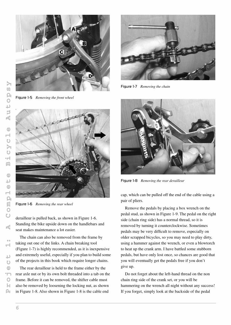
Remove the front wheel by loosening the two axle
nuts so it can fall out for the fork dropouts. Of course,
you must first release the front brake pads, or the wheel
will become stuck between the brake pads and the front
tire. Letting out all of the air in the front tire will also
work, but simply releasing the front brake pads is much
easier. As per Figure 1-5, press the brake arms together
so the cable head can be removed from the brake arm
slot (D). Also shown in Figure 1-5 is the cantilever
studs (A), which have a built-in return spring, so keep the
brake pads (C) away from the rim when not in use. The
brake pads can be adjusted for different rim style by
moving them along the brake arm and then locking them
in place with the brake pad bolts (B). Properly adjusted
brakes should not rub on the rim when idle, but sit as
close as possible to the rim.
The rear wheel will come free from the rear dropouts
once the rear axle nuts are loosened and the rear
5
Project
1:
AComplete
Bicycle
Autopsy
Figure 1-5 Removing the front wheel
Figure 1-6 Removing the rear wheel
derailleur is pulled back, as shown in Figure 1-6.
Standing the bike upside down on the handlebars and
seat makes maintenance a lot easier.
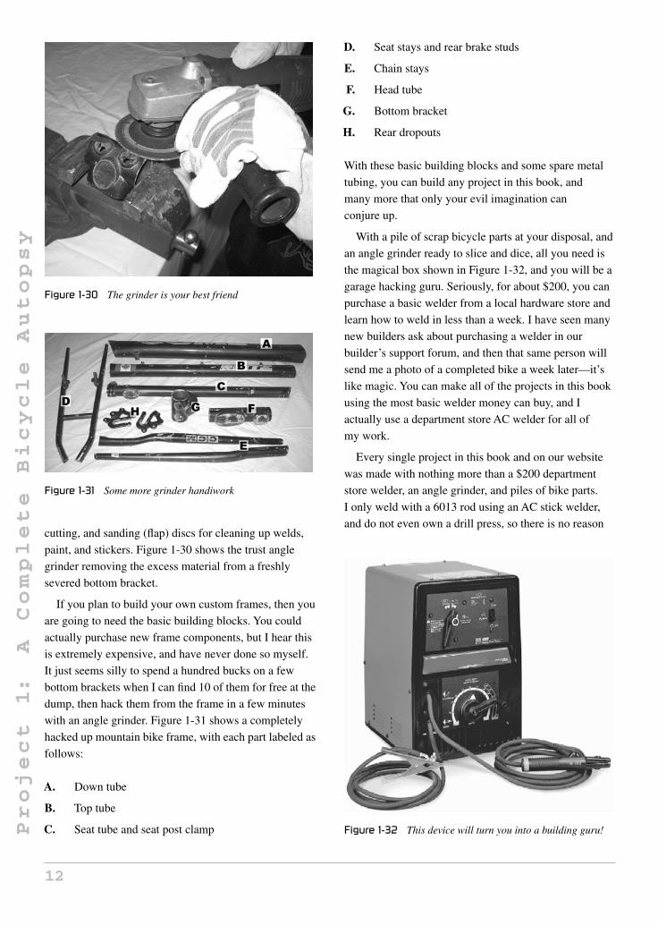
The chain can also be removed from the frame by
taking out one of the links. A chain breaking tool
(Figure 1-7) is highly recommended, as it is inexpensive
and extremely useful, especially if you plan to build some
of the projects in this book which require longer chains.
The rear derailleur is held to the frame either by the
rear axle nut or by its own bolt threaded into a tab on the
frame. Before it can be removed, the shifter cable must
also be removed by loosening the locking nut, as shown
in Figure 1-8. Also shown in Figure 1-8 is the cable end
Figure 1-7 Removing the chain
Figure 1-8 Removing the rear derailleur
cap, which can be pulled off the end of the cable using a
pair of pliers.
Remove the pedals by placing a box wrench on the
pedal stud, as shown in Figure 1-9. The pedal on the right
side (chain ring side) has a normal thread, so it is
removed by turning it counterclockwise. Sometimes
pedals may be very difficult to remove, especially on
older scrapped bicycles, so you may need to play dirty,
using a hammer against the wrench, or even a blowtorch
to heat up the crank arm. I have battled some stubborn
pedals, but have only lost once, so chances are good that
you will eventually get the pedals free if you don’t
give up.
Do not forget about the left-hand thread on the non
chain ring side of the crank set, or you will be
hammering on the wrench all night without any success!
If you forget, simply look at the backside of the pedal
6

Project
1:
AComplete
Bicycle
Autopsy
Figure 1-9 Removing the pedals
Figure 1-10 There are left and right pedals
stud, where you will find an L or R stamped on to
indicate which pedal you are working on. As shown in
Figure 1-10, the L indicates a left side pedal, so you turn
the wrench clockwise to loosen it.
The crank arms on a three-piece crank set are fastened
to an axle by a bolt through the centers. As shown in
Figure 1-11, the small plastic cap must by removed in
order to get to this bolt. If the cap is slotted, it will
unthread using a large flathead screwdriver. If it is just a
cap, then pry it off with a screwdriver blade.
The crank axle will either have a nut or a bolt, but both
threads are normal threads, so the wrench will turn
counterclockwise to loosen the part. Figure 1-12 shows
the socket wrench used to remove the bolt.
The crank arm may be another stubborn part to
remove, especially if some corrosion has built up
Figure 1-11 Removing the crank arms
Figure 1-12 Removing the crank axle bolt
between the axle and the crank arm. Use a long bolt, or
some type of steel wedge to help bang off the crank arm,
as shown in Figure 1-13. The wedge should always be
placed in the crank arm and not the chain ring, or the thin
chain ring will be bent. Again, a little heat via the
blowtorch may make a really stuck crank arm budge.
Usually, handle grips can be removed by forcing them
off from the inside edge. Of course, they may be glued
on, or so stuck that you have to use the “ugly method” of
removal, as shown in Figure 1-14. A single cut with a
razor knife will get them off every time, but they are
going straight in the trash can after that.
The handlebars are held in place by the clamp at the
end of the gooseneck, and can be removed by loosening
the nut as shown in the upper half of Figure 1-15. You
will need the handle grip and levers removed from at
least one side of the handlebars, so they can slide through
the clamp before removing them completely. The actual
7

Project
1:
AComplete
Bicycle
Autopsy
Figure 1-13 Removing the crank arm
Figure 1-14 Removing old handle grips
gooseneck is held into the fork stem by a wedge shaped
nut that is released by turning the bolt in the center of the
gooseneck, as shown in the lower half of Figure 1-15.
A common “newbie” mistake is to loosen the
gooseneck bolt as shown in the last photo, then start
cranking the handlebars left and right, while trying to lift
the gooseneck from the fork stem. Because of the way the
wedge-shaped clamp locks in place, simply loosening the
bolt in the center of the gooseneck will not always free it.
You must tap the bolt down about ¼ inch after loosening
it, as shown in Figure 1-16, in order to free the wedge.
As you can see in Figure 1-17, the wedge-shaped
clamp will slide along the angled cut, creating a
tremendous amount of friction in the fork stem, holding
the gooseneck in place. Often, you can completely
Figure 1-15 Removing handlebars and gooseneck
Figure 1-16 Removing the gooseneck
Figure 1-17 The wedge-shaped gooseneck clamp
8

Project
1:
AComplete
Bicycle
Autopsy
Figure 1-18 Removing the seat and seat post
remove the long bolt and still have the wedge stay
securely fastened in the fork stem, which is why the
tapping of the bolt head is necessary. Also, there are two
common sizes of gooseneck stems, so do not put the
smaller size in the larger sized fork stem or you may not
get a good lock.
Removal of the seat and seat post is nothing
special—just loosen the nut that holds the clamp around
the seat tube to release the seat post. It is best to leave the
seat installed when you take out the seat post—this way,
you can use it as a place to hold onto, as you turn the post
around while pulling upwards on the seat. Figure 1-18
shows the loosening on the nut around the seat post
clamp.
The front forks have a threaded stem and are held in
place by a threaded bearing race, a lock washer, and a top
nut. The top nut can be removed by turning it
counterclockwise, as shown in Figure 1-19. The lock
washer and bearing race will usually come free by hand,
as they are not supposed to be very tight. The lock
washer has a tab, so it must be lifted straight off the fork
stem, and the bearing race will unthread just like the top
nut did.
The fork bearings will fall out of the head tube cups
once the forks have been removed. As shown in
Figure 1-20, the bearings have two sides, a ball side and
a ring side. Always place the bearing in the cups’ balls
first, or they will not work properly. A stiff fork that does
not spin freely is a clear sign of an improperly installed
or wrong size bearing in the head tube cups. Yes, there
are several sizes of bearing and cups, so keep the same
parts together.
Figure 1-19 Removing the front forks
Figure 1-20 The fork bearings
The fork hardware is shown in Figure 1-21. There will
always be two bearings of equal size, a bearing race
(larger ring), a lock washer (thin ring), and a top nut.
Again, the bearings, cups and races must all match, so
keep them all together as a set when salvaging bike parts.
Often, you will need to remove the head tube cups to
weld or cut a head tube. Simply bang them out from the
inside of the head tube, as shown in Figure 1-22, using
some scrap steel rod or a long bolt. A few taps on each
side of the cups should set them free with little effort.
The head tube cups shown in Figure 1-23 have two
different heights. The larger cup is for the bottom of the
head tube and the smaller one is for the top. If you put
them in backwards, the fork hardware will not work
9

Project
1:
AComplete
Bicycle
Autopsy
Figure 1-21 The fork hardware
Figure 1-22 Removing the head tube cups
Figure 1-23 Head tube cups have a top and bottom
correctly, and the forks will seem very stiff when they are
turned.
The rear suspension spring is held in place by the
gussets on the frame and rear triangle by a pair of hollow
bolts. Simply find the appropriate size hex keys, and
remove the two bolts, as shown in Figure 1-24. Don’t
Figure 1-24 Removal of the rear suspension spring
Figure 1-25 Removal of the rear triangle
worry, as the spring is not under any tension and will not
go flying around the room once it is freed.
If your frame has rear suspension, then the entire rear
triangle will come free from the frame by removing the
bolt that holds it onto the pivot tube. This pivot is also
fastened by a hollow bolt that requires a pair of larger
hex keys to undo, as shown in Figure 1-25. You may
have to tap one of the bolt halves out with a hammer
once releasing the first bolt.
Figure 1-26 shows the rear suspension pivot parts once
they are removed. The small tube that is welded to the
frame has a pair of plastic plugs that act as a bearing
surface for the pivot bolt, so don’t forget to tap them out
of your plan on welding or cutting this tube. Some higher
quality suspension frames may actually have a bearing in
place of the plastic plugs.
10

Project
1:
AComplete
Bicycle
Autopsy
Figure 1-26 The rear suspension pivot hardware
Figure 1-27 Taking apart the bottom bracket hardware
To remove the bottom bracket hardware, start by
loosening the locking ring on the left side of the frame by
turning it counterclockwise, as shown in Figure 1-27.
This ring locks the bottom bracket bearing cup in place,
and should be easy to remove by tapping on the slot with
a hammer and chisel, or by using a pip wrench to grab it.
Once the locking ring is removed, the bottom bracket
bearing cup will also unscrew from the left side of the
bottom bracket shell in the counterclockwise direction.
This cup will probably have a face that can be held with a
wrench, and may require a bit of force to turn. When you
free this cup, the two bearings and crank set axle will be
freed, as shown in Figure 1-28. Just like the fork
bearings, it’s always balls into the cups, not the other
way around. Also note that I never remove the right side
cup from a bottom bracket, as this cup has a reversed
thread and is a real pain to get out. There is usually no
reason to remove it, and by leaving it in place, you never
accidentally try to install a bottom bracket in reverse or
thread the wrong cup into the wrong side.
Figure 1-28 Removing the bottom bracket hardware
Figure 1-29 Scrounging for bicycle parts
Once you get bitten by the bicycle building bug, you
will want to increase the size of your junk pile, so you
can spend more time building and less time scrounging.
Head to the local dumps and see if there is a “good
neighbors’ corner” or metal recycling area. Check your
local scrapyards and flea markets, and hit yard sales. Tell
all your friends and family that you take all metal scrap,
especially bicycle parts, and before you know it, your
garage will have a wonderful pile of junk for you to work
with. I am lucky enough to have a metal scrap pile at the
local city dump, where I can easily find 10 or more bikes
every day I visit, but even if you have to dig around for
junk, it doesn’t take all that long to accumulate a huge
collection of parts. Figure 1-29 shows a typical day at my
favorite hardware store—the city dump scrap pile.
An angle grinder is a must for this hobby. This simple
and inexpensive tool will be your most used weapon, and
can reduce a frame into its individual components in
minutes. You will also want three kinds of discs for your
angle grinder: standard grinding discs, zip discs for
11
Project
1:
AComplete
Bicycle
Autopsy
Figure 1-30 The grinder is your best friend
Figure 1-31 Some more grinder handiwork
cutting, and sanding (flap) discs for cleaning up welds,
paint, and stickers. Figure 1-30 shows the trust angle
grinder removing the excess material from a freshly
severed bottom bracket.
If you plan to build your own custom frames, then you
are going to need the basic building blocks. You could
actually purchase new frame components, but I hear this
is extremely expensive, and have never done so myself.
It just seems silly to spend a hundred bucks on a few
bottom brackets when I can find 10 of them for free at the
dump, then hack them from the frame in a few minutes
with an angle grinder. Figure 1-31 shows a completely
hacked up mountain bike frame, with each part labeled as
follows:
A. Down tube
B. Top tube
C. Seat tube and seat post clamp
D. Seat stays and rear brake studs
E. Chain stays
F. Head tube
G. Bottom bracket
H. Rear dropouts
With these basic building blocks and some spare metal
tubing, you can build any project in this book, and
many more that only your evil imagination can
conjure up.
With a pile of scrap bicycle parts at your disposal, and
an angle grinder ready to slice and dice, all you need is
the magical box shown in Figure 1-32, and you will be a
garage hacking guru. Seriously, for about $200, you can
purchase a basic welder from a local hardware store and
learn how to weld in less than a week. I have seen many
new builders ask about purchasing a welder in our
builder’s support forum, and then that same person will
send me a photo of a completed bike a week later—it’s
like magic. You can make all of the projects in this book
using the most basic welder money can buy, and I
actually use a department store AC welder for all of
my work.
Every single project in this book and on our website
was made with nothing more than a $200 department
store welder, an angle grinder, and piles of bike parts.
I only weld with a 6013 rod using an AC stick welder,
and do not even own a drill press, so there is no reason
Figure 1-32 This device will turn you into a building guru!
12

Project
1:
AComplete
Bicycle
Autopsy
why anyone can’t build all of the projects presented here.
If you really want to become a master of the arts, then
you can take a welding course, which is usually only a
few weeks long, and will teach you the finer points of
welding. So, if you are just starting out, head down to the
welding supply house and tell them you want a decent
beginners’ welding rig that will plug into whatever power
source you have in your garage and allow you to weld
thin walled tubing.
In addition to that basic welder, you will need a box of
rod or wire (depending on your choice of welder), a pair
of decent work gloves, a chipping hammer, welding
helmet and, of course, some type of eye protection.
Again, let me say that I only own a very basic AC welder,
an angle grinder, and the gear shown in Figure 1-33, yet
there is probably no vehicle I cannot build with these
tools. I have no drill press, lathe, tube bender, or chop
saw, so if I can make these cool machines, then so can
you. With a little practice, you will be able to create
Figure 1-33 Here is your battle gear!
a showroom custom, and have the ability to turn your
wildest imagination free, creating one-of-a-kind custom
vehicles that rival any of the mass produced department
store bikes available. So get that welder plugged in,
collect a pile of junk and get to work!
13

This page intentionally left blank

Section 2
Attitude and Style
15Copyright © 2008 by The McGraw-Hill Companies, Inc. Click here for terms of use.

Project
2:
The
Gladiator
Chopper
Project 2: The Gladiator Chopper
The Gladiator Chopper is an over-the-top custom
made from a fusion of bicycle parts, car parts and
commonly available steel tubing. What surprises most
people who ask me questions when I am out cruising on
the Gladiator is that the entire chopper was made from
junk parts using only a basic AC welder, an angle grinder
and a hand drill. Yes, no other tools were used, and not
one single part was machined or hard to find. This bike is
proof that anyone with the drive to turn their ideas into a
rolling work of art can do so without dropping hundreds
of dollars at the machine shop, or requiring many years
of mechanical or welding experience. I’m not going to lie
to you—there is a lot of physical labor involved in
making a bike like this, but the results are well worth the
effort, since you will end up with a custom bike that will
outshow any department store chopper that has been
mass produced on an assembly line. Yes, I have a
problem with a mass produced chopper—that is obvious
in my writings! I mean, how can a bike with a six-digit
serial number be considered a custom at all? A chopper,
as its name implies, is a “chopped” stock bike, so how
can one be mass produced and still be called a chopper?
Dude, this just isn’t right, which is why I built such a
radical bike using parts and tools that anyone with a little
love of the hobby could get their hands on.
Another thing that may surprise you when reading
through this plan is that there is no confusing CAD
drawing, jam packed with angles and measurements.
The entire project is done step-by-step in such a way that
you can substitute parts you have on hand, and make
modifications to suit your own style as each step
progresses. Yes, you can build your chopper exactly
like the Gladiator, as I have used the most common parts
I could find, but I challenge you to go out on a limb and
make slight modifications to the frame and parts used,
even if this is your very first attempt at building a bike.
I will give all measurements and details on the parts
I used, but do not be afraid to experiment, since your
own modifications will add a personal touch to your
chopper, making it a true custom.
It’s a good idea to read over the entire plan once before
hacking up any bikes or heading to the scrapyard on a
search for parts. By reading ahead, you will see why a
certain part was chosen, and get some ideas on how to
modify the design to suit your needs. With even a slight
change in a few of the main frame tubes, you could make
a completely different looking chopper, even though the
core design has been followed. Don’t be afraid to try new
things, and remember that hard work is what makes this
hobby successful, not spending money on mass produced
products. Long live the real custom!
We will be building the rear of the chopper first,
since it requires the most work and forms the building
foundation of the bike. Once the rear of the Gladiator is
complete, you have a lot more room to unleash your
creativity. Looking back on when I first began the
Gladiator concept, it’s hard to believe that I started
with nothing more than this old rusty pair of 15" x 7" car
rims (Figure 2-1), but I really wanted to turn the most
commonly available scrap into a rolling work of art, so
Figure 2-1 A pair of old 15" x 7" steel car rims
16Copyright © 2008 by The McGraw-Hill Companies, Inc. Click here for terms of use.

Project
2:
The
Gladiator
Chopper
these rims were perfect. You can use practically any
type of car rim you like, as long as it meets two
requirements: it must be a 15-inch rim, and the center
should be welded to the rim so you can cut it out.
All rims will have a stamp on the inside showing the
size, with the first number indicating the diameter, and
the second indicating the width of tire that will be
needed. 15" x 7" is a very common rim size, but you are
free to use any width from 15" x 5" right up to 15" x 15",
if you can find a set of monster tires to fit such a beastly
rim. A 7-inch wide tire may not seem like such a
monster on a car, but remember that those fat
department store chopper rear tires are only 4.25 inches
in width, so any car tire is going to dwarf them in
comparison.
As for the rim diameter, 15 inches was chosen
because it is a perfect size to spoke up with standard
20-inch bicycle spokes. Any other rim size will require
you to find custom length spokes, which is indeed
possible, but best left for the advanced wheel builder.
I would recommend using a 15-inch rim to make things
easier, unless you are certain you can find spokes to fit
another size rim. Read ahead a bit and you will
understand why the common stock steel rims are the
ones you want, not some fancy aluminum aftermarket
types.
As shown in Figure 2-2, almost all steel rims are
held together by the welds around the edge of the
center on the backside of the rim. There will most
likely be five or six welds holding the center in place,
each with a length of approximately 3 inches. Some rims
may have an aluminum center that can be simply
smashed out, like the one I chose for my OverKill
chopper, but those require a bit more searching to locate,
and since we need two identical rims for the Gladiator,
I chose the most common style available. Of course, if
you have access to another style rim that will allow the
center to be removed with less work than grinding a
weld, then feel free to use it.
Figure 2-2 shows the welds circled in black marker,
along the edge of the rusty steel center. Since the rims
will need to be painted after the weld removal
surgery, a little rust is not such a big deal, but try to
avoid any rims that have obvious bends or nicks
around the edge, since they will not look good even
when painted. Many tire shops have a large collection of
suitable rims, so don’t be afraid to ask—they are often
Figure 2-2 The center of the rim is welded in place
sitting out back rusting away like the ones I salvaged
were.
The most useful tool next to the welder is the angle
grinder. Together, these two tools allow a garage hacker
to yield a power so great that anything can be
accomplished. I have built hundreds of bikes and other
wild machines over the course of 30 years, and to this
day have no desire to own any other tools besides the
welder, angle grinder and hand drill. I feel a great sense
of accomplishment when veteran customizers who own
tools worth more than the house I live in send me a
“thumbs up” email on one of my project designs.
Working as a minimalist also lets me share my hobby
with many who have never hacked a bike up before, and
just want an inexpensive hobby where hard work equals
results. Learn to handle an angle grinder and a welder
like a medieval knight wields a sword, and you will have
the power, I promise.
A “zip disc” or cutoff wheel is a grinder thin disc made
for cutting, and it can chop out a 3-inch weld like the one
in a rim in a few minutes. Figure 2-3 shows one of the
rim welds being cut by the 1/16-inch zip disc by running
the disc at 45 degrees to the rim center. Try to cut the
weld between the rim and center in such a way as to
minimize damage to the rim as much as you can, but
realize that some damage to the rim will occur. You will
be welding up any cuts you make in the rim and then
grinding the area clean, which is why it is not important
to search for perfect rims, only those that can be sanded
smooth and later painted.
When you have cut all the welds holding the rim
center in place, you will need to pound out the center
by striking the area near each weld, as shown in
17

Project
2:
The
Gladiator
Chopper
Figure 2-3 Grinding out the welds
Figure 2-4. A wedge-shaped tool, or a bit of solid
steel rod, will do this job, which requires you to
bash the living daylights out of the center in order to
break it free from the rim. The center was jammed
into the rim by a machine, so it’s not just going to
drop out, even if you have cut clean through all of the
welds, so hammer away at each weld, looking for signs
that the weld area has begun to separate. Once you see
the initial hairline crack on each weld start to form, a few
good slams at each weld will eventually drive the center
out of the rim, a little bit at a time. You must pound each
weld equally, in order to avoid getting the center of the
rim stuck at an angle, as it starts to move free from its
original position. If a weld is not letting go, recall the
grinder for another tour of duty, and eventually you will
win the war.
Depending on the width of your rim, the center may
have to be pounded some distance before it can be fully
removed like the one shown in Figure 2-5. My 7-inch
Figure 2-4 Pounding out the rim center
Figure 2-5 The rim center has been liberated
wide rim had a raised edge of approximately 2 inches, so
pounding out the center only took a minute or two with
my favorite large hammer. As you can see, there is a bit
of damage done to the rim as the grinder disc took a bite,
but that’s nothing a little bead of weld and some careful
grinding won’t fix. Even if you cut right through the rim,
have no fear, as it will all work out in the end. Now do
the same thing with the other rim, and then throw the
centers into your junk pile for later use in some other evil
creation.
Figure 2-6 shows the result of 20 minutes of hard labor
with a grinder and hammer—a pair of 7-inch wide rims
that actually look like they were designed for spoked
wheels. You will probably be amazed at how much
lighter the rims are with the centers gone, weighing in at
less than half their original weight. Sure, the pair of rims
outweighs a typical full bicycle, but dude, we are not
Figure 2-6 A pair of seriously wide bicycle rims
18

Project
2:
The
Gladiator
Chopper
running the Tour de France now, are we? A chopper pilot
gauges performance on how many people gawk at you as
you cruise by, not by how many ounces you can shave
off your bike by drilling holes in the frame! The funny
thing is I think the Gladiator actually rides pretty smooth
for a bike with car wheels, and it can glide forever once
you get rolling. Now, exercise is finally cool.
Unless you are a magician with the angle grinder,
the rims will have some battle damage after cutting
away the welds, so you will have to fill and grind the
area. Figure 2-7 shows a bead of weld filling the
areas where I dug into the rim when cutting out the
center welds. Don’t be concerned about weld quality
here—just fill the holes with a light pass, with the current
as low as possible to avoid adding too much weld metal.
When grinding away the filler weld, start with a heavy
grinder disc and then switch to a smaller disc or flap disc
(sanding disc) to finish up the area. Try not to dig into the
original rim metal when grinding away the filler weld, or
it may show up as a flaw after painting the rim. Take your
time, and don’t be afraid to go over the area a few times
after grinding just to touch up the odd hole. I had to
touch up a few missed spots on each weld after grinding
away the filler welds shown in Figure 2-7.
With a little effort, the rims will clean up nicely after
welding and grinding any damaged areas from the
surgery. Figure 2-8 shows my rim pair after filling the
holes, grinding them flush, and then spending some
quality time listening to 1980s power metal with
sandpaper in hand. It took a bit of effort to sand all the
rust off the rims, but in the end, they look pretty decent,
and will certainly be fine after a fresh coat of paint.
If you really have a lot of time and like to build your arm
Figure 2-7 Welding up the rim damage
Figure 2-8 Repaired and sanded rims
strength, then keep sanding the rims with finer and finer
grits of sandpaper until they look like they are polished.
If you get the surface down to a shine, a clear coat could
be sprayed on the rims to make them look like chrome or
polished aluminum.
Everyone who examines the Gladiator is taken by the
fact that it has wheels that look like they are from a car,
yet have bicycle spokes. “Where did you get those
wheels?” I am often asked. “I made ’em from junk,” is
my standard response, which usually gets me a look of
disbelief, since they look like they were factory made.
Those who are interested in bicycles or mechanics will
often realize that the wheels are obviously custom jobs
and ask about the hubs. They are also amazed when I tell
them that the wheels actually have no hubs at all, just a
few hand-drilled washers from the hardware store. What
you see in Figure 2-9 is all that holds the rim and spokes
to the axle, i.e. four standard steel washers!
Yes, indeed, for less than a dollar, you can make your
own chopper hubs. You need four steel washers with a
diameter of 2 inches, and a center hole with a diameter as
Figure 2-9 Making the hub flanges
19

Project
2:
The
Gladiator
Chopper
close to 3/4 inch as you can find. The thickness of the
washer should be less than 1/8 of an inch, but no thinner
than 3/32, which is pretty much standard for 2-inch
diameter washers. You may need to sort through a bunch
of these washers at the hardware store to find four that
have identical thicknesses, because washers are often
made as “random thickness” for some reason which
defies all logical thinking. I went to the hardware store
and asked if I could pick out four 2-inch diameter steel
washers that have a 3/4-inch hole. Tell them you need
four with the same thickness and they will probably
understand. If you are not good at eyeing up small
measurements, just look at the hub flanges on a typical
rear bicycle rim and that will give you an idea of what
thickness you are after.
Shown in Figure 2-9 is a paper template that can be
taped over the washer in order to center punch the 28
spoke holes that need to be drilled in each flange,
creating a wheel with 56 spokes. If you would like a copy
of this hub template, a copy can be found on our website
at www.atomiczombie.com/support/gladiatorhub.jpg
Because there is no way to ensure that the image will
print out at the correct size on your printer, I have made it
very large, so you can scale it and print it by trial and
error until the pattern fits perfectly over your washers.
If you want to make your own template using a computer
program, or like using a compass, then 28 points on a
circle will require a hole every 12.857 degrees. The hole
centers should be 1/8 of an inch away from the edge of
the flange.
Figure 2-10 shows how the template can be used to
center punch the holes that need to be drilled in each
washer to create the hub flanges. If you use the provided
template, it should be scaled down until it fits perfectly
over the washer once carefully cut around
Figure 2-10 Using a template to punch the spoke holes
the circumference. Use the center circle as a guide by
holding the washer and template up to a bright light, so
you can make sure the two are aligned as perfectly as you
can get them. Four pieces of clear tape can be used to
hold the template to the washer, as you punch out all
28 holes with a center punch.
If you plan to make your own template, or directly
mark the washers with a compass, just remember that
there are 28 holes, which makes 12.857 degrees
between holes (360/28), and that there should be 1/8 of
metal between the edge of the washer and the center of
the hole. If you hate messing around with computer
software, and think using a compass is just too nerdy,
then have a buddy who knows how to use a
CAD program print you an appropriate
template.
I have built several human-powered vehicles using this
“hubless” approach now, and it may seem like a lot of
work to drill all 112 spoke holes, but like any task, it’s no
big deal if you do it a little bit at a time. As shown in
Figure 2-11, I like to screw the washer down to a bit of
plywood and then go to town with the drill. I only have
a hand drill, but the job only takes about 30 minutes per
washer, with a break every seven holes or so. The holes
are drilled using a 3/32 drill bit, which can easily be
broken if you press down on it too hard, so take your
time. I would recommend purchasing four high quality
3/32 drill bits, because 112 holes is a large number of
holes, and you have a good chance of breaking a bit or
two along the way. If you have a drill press, then this job
will seem a lot easier, but again, this is not a requirement.
I am often asked in the Atomic Zombie forum if a slight
error on one or two holes is a big problem, and the
Figure 2-11 Bolting down the washer for drilling
20

Project
2:
The
Gladiator
Chopper
answer is no. Once you get the spokes installed, any
small drilling error will be taken up by the spokes as they
are tightened.
If you take a look at a bicycle hub, even a cheap
one, you will notice that each spoke hole has been
beveled like the holes on the left washer shown in
Figure 2-12. The reason this is done is so that the
sharp edge of the spoke hole does not cut or damage
the spoke when it is under tension. To bevel each hole
(on both sides), simply take a 3/8 drill bit and run it
very lightly for a few seconds in each hole, so it just
removes the sharp edges of the hole. Try to keep the
drill running at the same speed as you do this, so you
can get the same bevel each time, and do not press too
hard or the bevel will be too deep. Bevel each hole on
both sides of all four flanges—this job should only take a
few minutes.
Another reason for the beveling of the spoke holes is
so the spoke can make it around the bend, as shown in
Figure 2-13. If your washers are a bit on the thick side,
then you may need to bevel the holes a bit more to get the
spoke around the bend without having to force it. The
spokes I recommend are 14 gauge with a length of
178mm, but if you plan to use heavier spokes, then the
Figure 2-12 Beveling each spoke hole
Figure 2-13 Testing the holes with a spoke
original 3/32 hole may not be large enough. Before
moving ahead, find at least one spoke of the required age,
and test several of the holes to make sure no extra
drilling will be necessary. Fourteen-gauge spokes are
fairly common on most 20-inch rims with 36 or more
spoke holes.
The Gladiator has no hubs. The hub flanges will be
welded directly to the left and right axles, in order to
create a wheel that includes the axle and rim as a single
unit. The advantage of this approach is simplicity,
strength, and cost. Having a hub machined and drilled
could cost a few hundred dollars, and this would be a
waste, since it would then have to be held to the axle
using a cotter pin or bolt, which would make the bolt the
weak link. By creating an integrated hub axle, you get a
bulletproof design for mere pennies, and do not have to
worry about any ugly lock nut or cotter pin sticking out
past the “beauty” side of the wheel. I have used this
design on many successful vehicles such as the
DeltaWolf, and the Kyoto Cruiser, which has a payload
of more than 500 pounds, and I can tell you that it is far
superior to any system that retrofits a hub onto an axle.
The final design is also very clean looking, as you can
see in the glamour shots.
The axles are made from 3/4-inch diameter mild steel
rod, as shown in Figure 2-14, along with the completed
hub flanges. Mild steel does not mean that the steel is in
some way weak—it just means that it is not hardened,
so welding it will not be a problem. Superior ground rod
could also be used, but ask your distributor about the
hardness of the material, letting them know that you plan
to weld a hub to it. Be aware that 3/4 axles will never
bend, and can easily support a heavy-set rider, so there is
no need to use a larger diameter axle. You could however
Figure 2-14 Steel axles and hub flanges
21

Project
2:
The
Gladiator
Chopper
get away with 5/8 axles, but this would require some
planning, especially when it comes to the hub flanges,
since washers of 2-inch diameter will be difficult to find
with a 5/8 hole. Again, this is not a bike for spandex-clad
cyclists, so just go with the 3/4 axles, and you will never
have a problem, ever.
You will need at least 36 inches (3 feet) of 3/4 rod for
the axles, since there are two axles, each with a length of
18 inches if you have 7-inch wide rims. I would
recommend you ask for 6 feet of rod, since you may want
to make your chopper a little wider, or use wider rims,
and because it is extremely helpful to have a spare 2-foot
rod to help center the bearings, as you will see by reading
ahead a bit. If your supplier has a pile of rod already cut
up, ask them for enough rod to make three 24-inch
lengths, and then you can cut them down later. Too much
is always better than too little!
Cut your axles into two 24-inch lengths. In the end,
my axles were only 18 inches each, but you may want a
wider bike to accommodate a wider butt, or wider rims,
so it’s better to work with more than necessary here.
Since the washer is made to fit over a 3/4 bolt, there is
a bit of play around the hole and the axle, which is not a
problem, and may even facilitate a better weld. As shown
in Figure 2-15, two tack welds are placed on the joint so
the gap is approximately equal all the way around the
hole. If you can’t do this by hand, then wrap the axle in
some paper to hold it in place while you make the two
tack welds. Try to get the washer tack welded to the axle
as accurately as you can, so it appears straight as you roll
the axle along your workbench. With only two small tack
welds holding the washer, you should be able to tap out
any obvious misalignments with a hammer. If the washer
is seriously out of alignment, then break the tack weld
Figure 2-15 Fitting the washer to the axle
and try again. Perfection is not necessary, but obvious
flaws should be repaired. I also recommend you tape up
the spoke holes when welding to avoid spatter in the
holes.
If you are happy with the hub flange alignment, then
add two more tack welds and recheck your work. With
four solid tack welds, you can then weld the entire joint
as shown in Figure 2-16, using a good solid bead all the
way around. Don’t worry about beauty here—just fill in
the area with solid weld metal, and it will be ground flush
later.
The inside of the hub flange can be welded once the
outer weld is completed. Take your time and weld around
the entire joint in three or four passes until it looks like
the weld in Figure 2-17. This weld does not have to be
extremely heavy, since the outer weld has closed the gap
between the washer and the axle.
Figure 2-16 Outer hub flange welded to the axle
Figure 2-17 Inside hub flange welding completed
22

Project
2:
The
Gladiator
Chopper
Once both sides of the flange are welded to the
axle, grind the outer face flush, as shown in
Figure 2-18. You may need to fix a few holes once
you grind the face, but with a few pokes of the welding
stinger and a little grinding effort, the face will look as
though it were machined from the same material that
makes up the axle, for a nice, clean, final product.
To get the face looking smooth, rough grind with a heavy
disc, then take off the last bit of material with a sanding
disc. Avoid cutting into the flange, or it will become
too thin.
The inside flanges are welded so that they are placed
apart at a distance of whatever width your rim happens
to be, as measured across the edges with a tape
measure. In Figure 2-19, the distance between the
flanges is 8 inches because that’s how wide the rim was.
Yes, a 15" x 7" rim is actually 8 inches wide, but is
made for a 7-inch wide tire. This discrepancy is because
the tire and rim are measured by the bead of the tire, not
Figure 2-18 Cleaning up the outer flange face
Figure 2-19 Hub axle units completed
the overall width of the rim as measured with a tape
measure.
The inner flange only needs to be welded on the inside,
as shown in Figure 2-19. The side that will face the
bearing is not welded because it will not be seen, and is
really not necessary. If you did weld both sides, this
would not hurt anything, though. The same alignment
technique is used on all four flanges, making them as
straight as you can. Again, do not freak out if there is a
slight wobble or hop in the flanges as you spin the axle,
as the spokes will take this error up. Obvious flaws that
can be seen without having to spin the axle should be
repaired.
Each rim has 56 spokes, which in reality form a
28-spoke wheel on each side of the rim. This may seem
odd since bicycle rims have the spoke holes in the center
of the rim, but due to the fact that the car rim is so wide,
it would not make a very strong rim if the spokes were
placed in the center of the rim, leaving so much of the
rim unsupported. By working with the rim as if it were
two rims (one at each side of the rim), the resulting wheel
is extremely strong and looks filled in. If you have had a
chance to see those fat department store chopper wheels,
they look somehow “sparse,” as if the designer simply
took a standard bicycle rim and made it wider, leaving
empty space on each side of the spokes, which is
essentially what they did. Personally, I think the beauty
of the nice, fat 4-inch rim is lost due to the
wimpy-looking hub and spokes, as if the next ride over a
curb could fold the wheel like a wet taco.
OK, so how do you mark out 28 evenly spaced holes
around the outside of the rim without a math degree?
My favorite trick is to drop a 28-hole rim over the car rim
and then place a square over each hole to transfer the
mark down to the rim. As shown in Figure 2-20, this
method is simple and fairly accurate, if you take your
time and keep your marker pointing in the same direction
as you work around the rim. I like to tape the rims
together, then have a helper carefully rotate the rim, as I
stand in the same place and make the two sets of points
with a sharp marker. The points are made on the little
gutter of the rim, just inside the outer edges of the rim.
This is the area that is recessed if you look inside the rim,
which makes it easy to line up all the holes as you drill
them. An alternative method of marking the holes would
be by calculating the exact circumference of the outside
of the rim, then dividing this distance by 28, and using
23

Project
2:
The
Gladiator
Chopper
Figure 2-20 Marking the rims’ spoke holes
the resulting number to mark each successive hole. The
problem with that system is that each error is simplified
by the next hole.
Whatever method you use to mark the rim, just ensure
that you take the valve stem hole into account, making
sure it is between the holes, and does not end up too
close to a hole. Start the first spoke hole near the valve
stem hole so you do not forget it is there.
When all of your holes are marked, and you know the
valve stem hole is not an issue, center punch each
marked spot and then find a nice sharp drill bit and go to
town. You can probably get away with a 3/16 bit for the
spoke nipple, but if the hole seems a bit snug, move up to
a 13/64 drill bit. The spoke nipple should have enough
room to tilt slightly so it can point towards the spoke,
which is at a slight outwards angle as it heads to the
flange. Some spoke nipples are a little larger than others,
so try a 3/16 hole first. To drill all the holes, place the rim
on the workbench, as shown in Figure 2-21, then use
your body to press the drill so you do not get tired as you
drill. In this photo, you can clearly see the raised area of
the rim that creates the thin well on the inside of the
rim—this is the area that is being drilled.
Figure 2-22 shows the completed hub axles and drilled
rims with a fresh coat of primer. I normally paint all of
the parts of a bike after everything is completed, but
since you need the rear wheels to complete the rest of the
chopper, they need to be painted ahead of time. The
spokes are put into the wheels after they are painted,
Figure 2-21 The drill gets another workout
Figure 2-22 Hub axles and rims getting primer
since it would look bad if the spokes were the same color
as the rim, and taping them all up to paint the rims would
be a ridiculous chore. The rear wheels are the focus of
this crazy chopper, so take your time and properly
prepare and prime the surface so your paint job looks
good. A spray can is all you need to do a professionally
looking paint job, but you will need to follow the
directions to avoid runs and streaks. Primer should also
cure for a day before applying any paint.
Wheel building is a skill that can take many years to
master, and is often thought of as a dark art by those
who have never tried it. Let me assure you that
building these wheels is not at all difficult, and will
require almost none of the skills a bicycle wheel
builder would need or even use. Because these wheels
are so different than any normal bicycle wheel, the
spoking technique I have developed is extremely simple,
and can be done by anyone that can turn a screwdriver.
Honestly, follow along, and you will have the wheels
24

Project
2:
The
Gladiator
Chopper
done in less than an hour each, without any pain
whatsoever.
Once your rims and hubs are painted and left to
cure for a few days (Figure 2-23), you can begin
installing all 112 spokes: 56 spokes per rim, 28 spokes
per side. I recommend you purchase new spokes to
build these wheels. New spokes will be made of
stainless steel, be all the same length, and of higher
quality than some you may find in salvaged kids’ bikes.
Of course, if your junk pile is well stocked, you may
have 112 equal length spokes, but for the cost of new
ones, it’s almost not worth the effort of unscrewing
them all. Go to your favorite bike shop and ask for
112 stainless steel spokes with a length of 178
millimeters and a diameter of 14 gauge. This is not an
odd request, and is a fairly common spoke, often used to
build 20-inch freestyle rims. If you like getting that
bizarre look, then tell the dude at the bike shop that you
plan on making a chopper trike with 15-inch car wheels
at the rear! Actually, many bike shops are keen on cool
customizing, so discussing your wild and crazy projects
may get you access to the pile of scrap in the back of
the shop.
I am going to make this easy and painless, with no
techno-babble or nerdy bicycle science! Start by dropping
in two spokes, as shown in Figure 2-24. The spokes are
put in so that the head is facing the outer sides of each
flange. Both spokes are in holes opposite each other on
both the rim and the flange so, essentially, you have hung
the hub axle from the rim. Push the nipple on to the
spoke thread and give it three turns. Until further notice,
you will give all spoke nipples approximately three turns,
so that they are all screwed in about the same amount.
So far so good, right? I told you this would be easy!
Figure 2-23 Getting ready to build the wheels
Figure 2-24 Beginning your wheel-building journey
Now, insert a spoke in every other hole, so that each
side of the rim has 14 spokes installed. Again, all spoke
heads are facing the outside of the flanges, as shown in
Figure 2-25. You now have a total of 28 spokes in your
wheel, and the hub axle is held in place, although it is
very loose at this point. If something looks messed up,
you probably skipped a hole, so double-check your work
to make sure there is a spoke in every other hole on both
the rim and the flanges. You are now half done! Say,
when does this get hard? Grab the long end of the axle
and give it a twist in either direction until all the spokes
are tight. As you can see, the spokes center the axle
perfectly when forced tight, which is essentially what the
next group of spokes is going to do.
As mentioned earlier, the next group of spokes will
be installed in such a way that they force the axle
to twist, making all of the spokes tighter by increasing
Figure 2-25 A spoke in every other hole
25

Project
2:
The
Gladiator
Chopper
the distance between the nipples and heads of each
spoke. If you want to follow along exactly, grab the axle
and turn it counterclockwise so the initial spokes tighten
right up. You may want a helper to turn the axle for you
so you can free up both hands for the rest of the job. Also
note that a spoke nipple may be caught outside the hole
in the rim, so wiggle the axle or offending spoke(s) until
they all drop in their holes and tighten up as you twist
the axle.
Now have a look at Figure 2-26 and trace the spoke
indicated by the large arrow back to the hub flange.
Notice that it is a newly installed spoke with its head
facing the other side of the flange. This spoke also points
in a direction opposite the other spokes, essentially
pulling the hub in the counterclockwise direction, much
like what your helper is patiently doing right now as your
read this. Have a good look at the photo and try to
understand what is happening with this new spoke, as it
is the only spoke you have to understand; all others just
drop right in from here, I promise.
Assuming that you are holding the axle in a
counterclockwise rotation, as shown in Figure 2-26, this
new spoke will have inserted six rim holes away from its
neighbor directly to the left. The spoke indicated by the
large circle is the neighbor to the left, and the rim holes
between the two spokes are numbered from 1 to 6. The
little arrow on the hub flange is pointing to the new
crossing spoke and his neighbor to the left. If this does
not make sense, then read it again and study the photo;
your helper will just have to be patient!
When you get that Eureka moment and it all makes
total sense, insert the remaining spokes based on this
Figure 2-26 Installing the first crossing spoke
“skipped-hole formula,” which is an easy task once the
first crossing spoke has been determined. The remaining
spokes are easy because they simply fit into every other
hole as you go around the rim. As long as you installed
the first crossing spoke correctly, the others will follow.
Figure 2-27 shows the other crossing spokes installed,
based on the “every other hole” technique. It may look
technical at this point, but all you did was shove a spoke
in every other hole with their heads facing the outside of
the flange, then reversed the direction, crossing a set
number of spokes as you installed the second group in
every other hole facing the inside of the flange. I know
that explanations can sometimes seem confusing at first,
but if you get that first crossing spoke in the correct place
and just keep going, the second time you do this will
seem a lot easier. I can build one of these wheels in
10 minutes, but the first time took me over an hour. Be
patient, be stubborn!
Figure 2-28 shows what the wheel will look like with
all 56 spokes installed. The other side of the rim follows
the same rules as the first side, inserting that magic first
crossing spoke 6 rim holes away from its leftmost
neighbor. Again, you will be turning each spoke nipple
three turns, so they are all put in at roughly the same
depth. Although the spokes are still somewhat loose, the
slack has been greatly reduced, and it may surprise you
that if you held the axle and gave the rim a spin, it would
run almost true already. A car rim is much too stiff to
warp, so the only thing you need to do now is crank all of
the spoke nipples the same amount as you work around
the rim. Unlike a thin aluminum bicycle rim, small
variances in spoke tension will not have much of an
Figure 2-27 All crossing spokes are now installed on one side
26

Project
2:
The
Gladiator
Chopper
Figure 2-28 The same rules apply on the other side
effect on the wheel, so go ahead and turn the spoke
nipples two full turns each as you work around the rim,
starting at the valve hole. Do both sides at the same time,
and keep working around the rim until you can no longer
make two full turns on each nipple. Basically, try to turn
all spoke nipples the same amount by hand. Do not use a
screwdriver yet.
The process is, of course, the same for the second rim,
and hopefully it will seem a lot easier. In Figure 2-29
I have fully installed all 112 spokes and hand-tightened
them all to approximately the same amount by working
around the rim, turning each spoke nipple only a little bit
at a time. The spokes are not extremely tight, but the rims
seem fairly true, even at this point, which is due to the
fact that they are extremely stiff, and the spokes are
pretty much all at the same tension. To finish up the rims
and tighten the spokes, we will mount the axles on a pair
of bearings so the rim can be spun and referenced to a
stationary object, much like the way a wheel builder
would use a truing stand to fine tune the spokes
and rim.
Figure 2-29 Hand-tight spokes
The pillow block bearings shown in Figure 2-30 will
hold the axles to the frame, and we will use two of them
temporarily to help finish the wheel-building process by
allowing the wheel to spin freely as you tighten each
spoke with a screwdriver. These bearings are common
items available at many hardware stores or industrial
supply outlets, and they are heavy duty enough to last
forever in our project. If you walk into a bearing store,
just ask for four identical pillow block bearings to fit a3/4-inch shaft. What you see in Figure 2-30 is what you
will get.
Figure 2-31 shows a simple makeshift truing stand
made by bolting down a pair of pillow block bearings to
your workbench, so you can spin the rim and reference it
against the edge of the bench. OK, it’s not really a truing
stand, but this system works great, and lets you work
around the rim, turning each spoke a small amount with a
screwdriver as you make sure the rim is coming out true.
The rim will most likely be very true as you give it a
spin, and as long as you crank down each spoke only a
little at a time, the rim should stay that way. A slight hop
Figure 2-30 Four 3/4-inch pillow block bearings
Figure 2-31 A makeshift truing stand
27

Project
2:
The
Gladiator
Chopper
up and down can be repaired by turning the spokes
opposite the “high side” down a little more than those on
the “low side.” There are so many spokes in each rim that
they don’t have to be cranked down so they are overly
tight. As a reference, feel the tension on a typical 20-inch
rim by squeezing a few spokes together—this is your
target tension. If you hear that “tink, tink, tink” sound,
then you are probably getting a little too much tension in
the spoke, so take it easy.
Again, turn each nipple only a little at a time as you
work around the rim, and you will most likely not have
to even worry about truing the rim, as it should fall right
into alignment. If the rim seems to pull to one side,
tighten the group of spokes on the other side to move it in
that direction. Patience is the key!
Obviously a rim with 56 holes drilled in it will no
longer hold air, so you can pop out the original valve
stem if you have not done so already. You will need a
pair of suitable inner tubes and some duct tape to cover
the spoke nipple, so that they do not damage the inner
tubes. As shown in Figure 2-32, wrap the area over the
spoke nipples with two turns of duct tape, so that there is
no chance of the spoke nipple puncturing the inner tube
when it is inflated. I also like to put a small amount of air
in each inner tube so it can be handled easily, rather than
fooling around with it as a deflated floppy mess.
Depending on the size and style of the tires you plan to
use, installation can range from easy to brutally difficult,
as I have found out in my adventures with car wheels.
On my OverKill chopper I manually installed a 15-inch
wide drag tire on a rim, and it took me all day, consumed
most of my screwdrivers as I snapped them one by one,
Figure 2-32 Cover the spoke nipples with duct tape
and almost tried my patience to the very end of its limits.
Of course, I would rather wrap myself in lunch meat and
run into a cave full of grizzly bears than give up on a job,
so I eventually beat the tire, and then crashed on the
couch for two days! Anyhow, you may want to grab a
helper, and get a spray bottle full of soapy water, as I
have found this makes a huge difference when installing
a tire the hard way.
To avoid scratching the paint on your rims, set up the
wheel on three buckets, as shown in Figure 2-33. Having
the wheel up off the ground makes the task much easier
for you and your brave assistant. Now, it may look like I
am a long way into the installation in Figure 2-33, but to
get to this point is not even a challenge—simply press
the tire onto the rim on an angle and it will almost fall on
by itself. It’s the top bead that is difficult, specifically the
last third, as shown in the photo.
When you get to the point shown in Figure 2-33,
hold the two screwdrivers on the tire so that the last third
of the bead is off the rim, then kneel on the opposite side
of the tire so that the bead drops into the rim well (the
narrower part of the rim as viewed from the inside). You
may want to have your helper force the tire into the well,
so your hand can be free to snap screwdrivers, I mean,
work the last part of the bead.
The reason you want to force the opposing bead into
the rim well is so that it does not have to stretch as far to
pop over the last third of the rim. By having your helper
kneel on the tire, as you carefully use three screwdrivers
to work the bead a little bit at a time over the rim, you
Figure 2-33 Manual tire installation
28

Project
2:
The
Gladiator
Chopper
should be able to get to the point shown in Figure 2-34 in
a few minutes. This tire was a joke compared to the
OverKill tire! I would honestly say that I have had more
trouble with some high pressure bicycle tires than I did
with this tire, but your experience may vary.
The arrow pointing to the bead in Figure 2-34 is
indicating the place where you would have your helper
use a third screwdriver to pop the last bit of the tire over
the rim. During this process, be careful not to scratch the
paint, or puncture the inner tube. Dude, you did install
the inner tube first, didn’t you? If you are having a
difficult time with the last part of the tire, spray some
soapy water into the bead and rim edge to make the
rubber slippery, as this really helps. I told you that this
hobby could be labor intensive! But hey, what would
your chop be worth if everyone could build one? You
will get rewarded for all your hard work in the end.
With both tires mounted on the rims, your last
wheel-building task will involve getting the bead to seat
properly. Because the spoke nipples are slightly raised on
the inside of the rim, the tire may need to be “coaxed” to
pop into the correct place between the spoke nipples and
the edge of the rim. First, try inflating the tire to
40 pounds, then let it sit for an hour, as the air pressure
may pop the tire into place. If this does not work, use a
spray bottle filled with soapy water to wet down the bead
and rim edge by letting the liquid run along the tire onto
the bead area. With the entire bead lubricated by the
soapy water, inflation of the tire should allow the bead to
pop into place. On one tire, 20 pounds of air pressure did
the trick, but on the other, it took over 40 pounds. Be
careful when exceeding a tire’s recommended pressure,
and do not exceed 45 PSI. Eye and ear protection should
be used when working with tires as well. When you have
Figure 2-34 The battle is almost won!
the tires sat properly, reduce the air pressure to 25 PSI,
which is plenty of inflation for such a light vehicle. As
shown in Figure 2-35, these rear wheels are seriously
cool! Because of the spokes, they no longer look like
typical car wheels, and people will often ask you where
you found such beastly bicycle wheels.
The Gladiator’s frame is based on a simple backbone
structure that looks like a pitchfork. As shown in
Figure 2-36, this simple design secures the rear axles to
the frame’s main tube, allowing you a great deal of
creative freedom once it is completed. If you are just
dying to add your own mods to my chopper design, then
fear not—the time is coming close, but I recommend that
you create the backbone as it is shown in the next few
steps, as it forms a solid foundation on which to add the
rest of the tubing and components.
The frame tubing is made from hardware store
conduit, which is thin walled tubing, sometimes referred
to as EMT. This tubing is lightweight and stiff, and it
comes in many diameters with pre-made 90-degree
factory elbows available. I used 1.25-inch conduit and
two factory elbows to create the frame, as shown in
Figure 2-35 You want phat? These are phat!
Figure 2-36 The frame backbone laid out
29
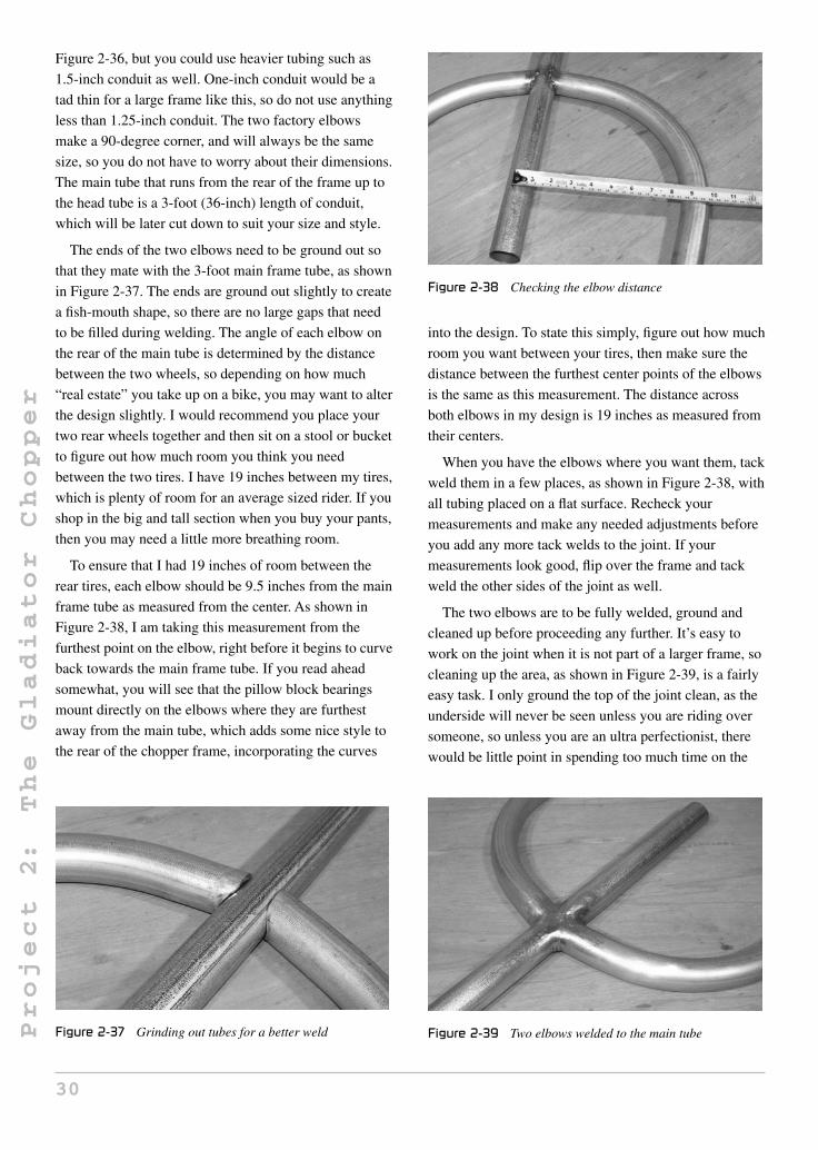
Project
2:
The
Gladiator
Chopper
Figure 2-36, but you could use heavier tubing such as
1.5-inch conduit as well. One-inch conduit would be a
tad thin for a large frame like this, so do not use anything
less than 1.25-inch conduit. The two factory elbows
make a 90-degree corner, and will always be the same
size, so you do not have to worry about their dimensions.
The main tube that runs from the rear of the frame up to
the head tube is a 3-foot (36-inch) length of conduit,
which will be later cut down to suit your size and style.
The ends of the two elbows need to be ground out so
that they mate with the 3-foot main frame tube, as shown
in Figure 2-37. The ends are ground out slightly to create
a fish-mouth shape, so there are no large gaps that need
to be filled during welding. The angle of each elbow on
the rear of the main tube is determined by the distance
between the two wheels, so depending on how much
“real estate” you take up on a bike, you may want to alter
the design slightly. I would recommend you place your
two rear wheels together and then sit on a stool or bucket
to figure out how much room you think you need
between the two tires. I have 19 inches between my tires,
which is plenty of room for an average sized rider. If you
shop in the big and tall section when you buy your pants,
then you may need a little more breathing room.
To ensure that I had 19 inches of room between the
rear tires, each elbow should be 9.5 inches from the main
frame tube as measured from the center. As shown in
Figure 2-38, I am taking this measurement from the
furthest point on the elbow, right before it begins to curve
back towards the main frame tube. If you read ahead
somewhat, you will see that the pillow block bearings
mount directly on the elbows where they are furthest
away from the main tube, which adds some nice style to
the rear of the chopper frame, incorporating the curves
Figure 2-37 Grinding out tubes for a better weld
Figure 2-38 Checking the elbow distance
into the design. To state this simply, figure out how much
room you want between your tires, then make sure the
distance between the furthest center points of the elbows
is the same as this measurement. The distance across
both elbows in my design is 19 inches as measured from
their centers.
When you have the elbows where you want them, tack
weld them in a few places, as shown in Figure 2-38, with
all tubing placed on a flat surface. Recheck your
measurements and make any needed adjustments before
you add any more tack welds to the joint. If your
measurements look good, flip over the frame and tack
weld the other sides of the joint as well.
The two elbows are to be fully welded, ground and
cleaned up before proceeding any further. It’s easy to
work on the joint when it is not part of a larger frame, so
cleaning up the area, as shown in Figure 2-39, is a fairly
easy task. I only ground the top of the joint clean, as the
underside will never be seen unless you are riding over
someone, so unless you are an ultra perfectionist, there
would be little point in spending too much time on the
Figure 2-39 Two elbows welded to the main tube
30

Project
2:
The
Gladiator
Chopper
underside of the joint. Always be careful not to take off
too much weld metal or dig into the original tubing when
cleaning up a weld. Start with a rough grinder disc, and
then complete the cleanup with a sanding disc.
Earlier in this section, I mentioned that it is a good
idea to have 2 feet of extra 3/4 axle material available,
and Figure 2-40 shows why. When you place a solid axle
through the two outer bearings, they instantly become
perfectly aligned, so you can mark the area where they
need to mount to the frame. I have built many trikes and
go-carts over the years, and I can guarantee you that
there is no better way to align your rear wheels than this
method. If you try to get this alignment by eye, it may
come close, and even look perfect, but any slight
misalignment in the rear wheels will cause a toe-in or
toe-out condition, which will limit your top speed and
create extra rolling resistance. In a car, tire scrub equates
to lower gas mileage and excessive tire wear. On an
80-pound, human-powered chopper, tire scrub equates to
a lot of rider huffing and puffing!
With your bearing mounted on the axle, drop them
onto the frame so that the axle crosses the frame at its
widest point on the two elbows, making it 90 degrees to
the main frame tube. Pillow block bearings allow the
bearing to move around to any angle, similar to a ball
joint, so tap the two bearing bodies with a hammer to get
their bolt centers onto the elbow center. As you can see in
Figure 2-40, the pillow blocks are on a slight angle so
they line up with the curved elbows, yet the axle is
parallel to the frame, and 90 degrees to the main frame
tube. When you have both bearings in the correct place
and angles on the elbows, use a marker to draw the bolt
holes on the elbows by tracing the entire bolt hole. Don’t
Figure 2-40 A good bearing alignment trick
forget which side of the frame is the underside—the
bearings mount on the underside of the frame.
To mount pillow block bearings to a tube, you would
normally drill through the tube and use bolts to hold the
bearings onto the tube. I wanted a cleaner look, showing
no bolt heads, so I decided to cut off a few segments of
threaded rod and weld them directly to the underside of
the frame where the bolts would have to go. The nice
thing about this design is that you do not have to drill any
holes into the frame tubing, there are no bolt heads
showing, and the tubing does not have to suffer any
crushing from the tightening of the bearing bolts. My
pillow block bearings needed half-inch bolts, so I cut
eight 1.5-inch segments from the half-inch thick threaded
rod, as shown in Figure 2-41. You could also cut the
heads off eight appropriate bolts, if you have them handy.
As shown in Figure 2-42, the bearing bolt segments
are welded to the underside of the frame in the exact
place you marked out the holes when you set up the axle
for alignment. Although the bearings will allow a bit of
Figure 2-41 Bearing mounting bolts
Figure 2-42 Bolts welded directly to the frame
31

Project
2:
The
Gladiator
Chopper
adjustment due to their slotted-hole design, try to get the
bolts as parallel as you can, and at a 90-degree angle to
the frame. The slight movement allowed by the bearings
will later be used to pick up any chain slack. To avoid
damaging the threads by welding spatter, tape the
threaded area when welding.
The beauty of the single-axle alignment system is
apparent when you are installing the two inner bearings.
Without the axle as a guide, you would have to venture
your best guess as to where exactly the two inner
bearings needed to be on the frame, in order to ensure
perfect rear wheel alignment. Using the axle as a
guide, it is impossible to make a mistake. Figure 2-43
shows a test fitting of the steel plate that will be used to
carry the two inside bearings. This plate is cut from some
scrap 3/32-inch steel plate and only needs to be large
enough to carry the two bearings. If, for some reason,
the elbows are higher or lower than the main frame tube,
due to heat distortion, you may need to add washers
under the two outer bearings to compensate. Do not
worry about this up-and-down misalignment; it will not
induce any extra tire friction, and will not show up in the
final design.
The four bolts needed to hold the two pillow block
bearings to the plate are first welded, and then the plate is
welded to the frame, as shown in Figure 2-44. There is
no guesswork involved in aligning this plate to the frame,
since the axle is doing it for you. Before you weld the
plate to the frame, make sure that both outer bearings are
bolted down tightly and in the center of their oblong
holes. The same goes for the bearing plate bolts. Try to
place the bolt in the center of the bearing holes, so there
is a little adjustment available in either direction later, as
this may be needed to pick up a slack chain.
Figure 2-43 Aligning the two inner bearings
Figure 2-44 Welding the bearing mounting plate to the frame
Figure 2-45 shows the two rear wheels mounted to the
frame. Obviously, the two axles needed a bit of trimming,
since they were left long at the beginning just to make
sure there would be enough material. The axle hubs
should butt up against the face of the outer bearings, and
no part of the tire or any spoke should rub on any part of
the frame. The distance between the tires should be pretty
close to the calculated distance, so check this before you
cut down the axles. Roll the assembly across your garage
floor, and it should move with almost no resistance, due
to the fact that the wheels are perfectly aligned.
From this point on, I turn over the creative torch to
you, as you can alter the frame in just about any way you
like, now that you have the rear wheels mounted to the
backbone. If you like my design, then follow the steps
exactly, but don’t be afraid to try your own thing. This
hobby is all about creativity. If you do decide to make a
radical mod, then read ahead to ensure that your changes
will allow things like transmission and steering parts to
Figure 2-45 Wheels mounted to the frame backbone
32

Project
2:
The
Gladiator
Chopper
work properly, as with a little planning, anything is
possible.
How tall do you want your chopper? On my OverKill
chop, I went sky high with the frame rise so my arms
would be reaching for the handlebars. On the Gladiator,
I planned to install a laidback seat with a backrest, and
wanted a more lazy sitting position, with handlebars
coming to me, so I kept the frame rise somewhat lower
this time. You should really find a seat base or board to
plunk down on the frame so you can see for yourself how
you may want to sit or reach for the handlebars. The rear
end shown in Figure 2-46 could easily be made into 100
totally different looking choppers by simply altering the
rest of the frame, so plan the design to fit your style and
seating requirements. To decide on a medium frame rise,
I placed this 17-inch tall plastic bucket under the main
frame tube just ahead of the wheels, as shown in Figure
2-46. I thought it looked good, so all other frame parts
will be based on this position. This may seem like a steep
frame, but as you will see in the next few steps, I toned it
down by using a pair of elbows to make a nice curve up
to the head tube. If you like straight lines, then a straight
tube up to the head tube will also look cool.
Bending conduit over 1 inch in diameter is just not
possible without some serious tube bending equipment,
and since I own nothing but a welder, grinder and hand
drill, bending the 1.25-inch conduit would be impossible.
To keep to the cool, sketched ideas I had for this chopper,
I made the S-shaped curve by welding a pair of factory
elbows together, as shown in Figure 2-47. You can make
just about any type of curve with a few elbows
depending on how you cut and join them, but since I
Figure 2-46 Choosing a frame rise
Figure 2-47 Making curves without a tube bender
wanted a large smooth S shape, they were simply welded
end to end. If you are designing your chopper visually,
then only tack weld the parts at this point, until you stand
back and think “damn, that’s what I want!” For
reference, the distance between each end of this S curve
is about 24 inches, but don’t get too tied up in exact
measurements here, as we are not building a helicopter.
After the two elbows were joined together to form the
nice flowing curves I wanted, the main frame tube had to
be cut down as it was way too long. I hacked the main
frame tube to a length of about 27 inches and then
welded the curved section in place, as shown in
Figure 2-48. By sitting on the exercise bike seat I
dropped on the frame, I could reach ahead and imagine
how the chopper would feel at this height and length. The
head tube would be fairly far ahead of me, but I intended
to install some very long handlebars, most likely home
built from more conduit and factory elbows. When you
lay out a bike visually, you have to imagine how you will
be seated when steering and pedaling, so take your time
and build it the way you want. For reference, the distance
from the very back of the main frame tube to the end of
Figure 2-48 Joining the frame tubing
33

Project
2:
The
Gladiator
Chopper
the curved section is now 52 inches, although I will most
likely be trimming a few inches off the end later.
Once you make a solid weld around a butted tube
joint, a little careful grinding can make the tube look like
it was made from a single piece. As shown in
Figure 2-49, there is no sign of any welding once the
weld is ground flush with the surrounding metal. The
success of this process involves making a solid initial
weld followed by a rough grinding and filling of any
leftover holes. The final grinding should be done with a
flap disc or sanding disc, so you are not digging into the
original metal or weld material between the joint—if you
take out too much metal and leave a dip in the joint, it
could become seriously weak, so be careful.
The Gladiator is a radical departure from a standard
bicycle, but many of the parts are in fact standard bicycle
parts, especially those in the steering and transmission.
A typical mountain bike head tube is shown in
Figure 2-50, ready to be ground clean. A mountain bike
head tube is perfect because it is made heavier than a
road bike head tube, and will usually have an overall
length of at least 6 inches. You could actually get away
Figure 2-49 Making a seamless weld
Figure 2-50 A head tube cut from an old frame
with just about any head tube and a matching fork stem,
but if you have the junk to pick through, locate a head
tube with a length of 6 to 8 inches.
With a little grinder magic, the head tube is free of any
original tubing “stubbage” and paint, making it much
easier to work with. A sanding disc takes paint off
instantly, and will save you from suffering that horrific
burning paint smell when you begin welding. Figure 2-51
shows the naked head tube ready for its new life.
A fork stem that matches the head tube will also be
needed. As shown in Figure 2-52, simply amputate both
fork legs, and then clean up the crown area using the
same technique used to clean up the head tube. The little
ring (bearing race) above the crown can be tapped off
with a hammer before grinding—this way it will not
suffer damage. Don’t worry too much about the condition
of the fork legs; just make sure the stem is not bent. This
fork set had been bent in a front end accident, but only
the legs were bent, so it was the perfect candidate for
hacking, and the stem length matched the head tube.
How long is long enough? Ah yes, the age-old length
debate is often a hot topic in the chopper world. I have
often heard that you do not need long forks on a chopper,
Figure 2-51 Cleaning up the head tube
Figure 2-52 Removing the fork legs
34

Project
2:
The
Gladiator
Chopper
but personally I think these words are only spoken by
those who have to drive a “shorty”! Seriously, though,
you can make your forks as long or as short as you want,
and I didn’t want to use any parts that would make this
chopper look stock! I was brought up believing that a
proper chopper should have long forks, so I decided to
make my fork tubing exactly 4 feet long. Maybe you
want to scare more of the roadies off the bike path and
think an 8-foot fork would be in order? Certainly, you
could do it—this is a trike, so there will not be any
balance issue to worry about. Now is the time to choose a
fork length, so put your head to the grindstone and hack
up some tube. The fork legs are made from the same
1.25-inch thin walled conduit as the rest of the bike. If
you want to use some other type of tubing, just make
sure it is no smaller than 1.25 inches in diameter if your
fork legs are longer than 3 feet.
The fork legs are held in place at the base of the fork
stem, as shown in Figure 2-53, using a pair of small
1-inch tubes to fasten them to the heavy crown area.
Round or square tubing will be fine for this job, and each
piece should be cut to 2.5 inches, then ground to conform
to both the fork crown and fork tubing.
Before you weld the lower fork leg support tubes in
place, as shown in Figure 2-54, read ahead so you
understand the relationship between the angle of the two
small tubes and the distance the fork legs need to be
placed apart in order to use a standard front bicycle hub.
As you will see, having the fork legs cut and ready will
greatly help at this stage.
A typical front bicycle hub needs the fork dropouts
spaced at 4.25 inches apart. You may have a different
Figure 2-53 Checking the head tube angle
Figure 2-54 Fork leg support tubes welded in place
fork design in mind, or plan to use a nonstandard front
hub, so consider this when choosing the width of your
front forks. You will be able to muscle a half inch either
way by squeezing or pulling the legs apart later, but try to
get things the way you want now to avoid force fitting
parts later. In Figure 2-55, both front fork legs are tack
welded to a scrap square tube so their centers are exactly
4.25 inches apart, which is the correct spacing for a stand
front bicycle hub, assuming the dropouts will end up in
the center of each fork leg. You can also see in
Figure 2-55 that the two fork leg support tubes fall right
into place, which is how I figured out what angle they
needed to be installed on the fork crown, as shown in the
previous photo. This scrap tube holding one end of the
forks also ensures that they end up parallel when the fork
stem is welded at the other end, as will be shown in the
next few steps. Again, work on a very flat surface, so all
tubing is perfectly parallel.
Before you weld the fork stem in place, as shown in
Figure 2-56, you must decide if you are going to have the
Figure 2-55 Setting the fork leg width
35

Project
2:
The
Gladiator
Chopper
Figure 2-56 Welding the fork stem in place
fork legs stick up past the top of the fork threads like my
design does, or go with the more conventional triple
tree-top plate design. If you look at a typical motorcycle,
there are two pairs of clamps holding the fork legs to the
fork stem—one at the base of the fork stem similar to
Figure 2-56, then a top plate that bolts to the top of the
fork stem and to each of the fork legs, essentially
capping them all off. This standard motorcycle design
can be used here as well, but I make it more stylish to
extend the fork legs up past the top of the frame and then
mount the handlebars to the side of the fork legs. Not only
does this give the chopper a more radical look, it allows
more diversity in the handlebar design. I extended my
fork legs 6 inches past the top of the fork stem, as shown
in Figure 2-56. The fork leg support tubes are first tack
welded over the marked areas to make sure all three
tubes (fork legs and stem) are perfectly parallel. Two
small tack welds on each tube should hold everything
in place so you can view it from all angles to check
alignment.
Figure 2-57 shows the scrap tube at the end of the fork
legs and the tack welded fork stem holding everything in
perfect alignment as viewed from the top end. Don’t be
afraid to break a tack weld and try again if things do not
look straight, as this is where it counts, and obvious flaws
will effect the steering. The fork legs are exactly 4.25
inches apart as measured from their centers. If you are
happy with the alignment, complete the welding around
the fork leg support tubing, starting with the top and
bottom welds. You may want to add another bit of scrap
tubing across the top end of the fork legs, just to ensure
nothing moves when welding.
Make sure your fork hardware has no damage.
Figure 2-58 shows the two bearing cups, bearings, and
Figure 2-57 Checking fork alignment
Figure 2-58 Checking the fork hardware
top fork hardware ready for installation. Do not grease
any bearing hardware until after the bike is painted, and
always remember the bearing orientation rule—balls go
into the cups.
As shown in Figure 2-59, the fork hardware should
install perfectly if your fork stem matches your head
tube. If the threads are too long, trim them down to fit. If
there is any excess friction when turning the head tube,
you may have installed the bearings backwards, or have
the wrong size cups or bearing hardware. There should
be very little friction when you twist the head tube.
Leave the head tube installed at this point, as it will be
needed to take a measurement when setting up the front
forks on the frame.
The Gladiator has a unique suspension system which I
call the “Inverted Springer.” The term “springer fork”
refers to a chopper fork that has rods running from the
hinged dropouts up to the top of the fork, where a spring
36

Project
2:
The
Gladiator
Chopper
Figure 2-59 Fork hardware installed
is compressed, creating a spring suspension for the front
wheel. I decided to use parts that I already had on hand to
build a springer fork, giving it a fresh look and requiring
much less work on the part of the builder. As shown in
Figure 2-60, the parts are made from a few tabs of flatbar,
four mattress or screen door springs, and a few bolts. The
springer system is easy to build, works very well, and lets
you bounce the front wheel off of the ground while you
are parked, just like those hydraulically activated low
rider hot rods. Hey, it’s all about the show with a chopper!
The tabs shown in Figure 2-60 are made from four
1.75-inch long pieces of 1/8 flatbar with a 3/4 hole drilled
at each end. The hole is half an inch from the end of the
flatbar, which is then rounded to take off the sharp
corners. Read ahead a bit to see how this suspension
system is made and you may get some modification ideas
of your own. The springs should be fairly hard to pull
apart, and you may need two or four, depending on their
strength.
The two fork legs shown in Figure 2-61 have been cut
from the leftover fork legs taken from the fork stem
Figure 2-60 Parts for the springer suspension
Figure 2-61 The pivoting fork legs
used earlier. Each leg is now 6 inches long and has a
small tube with a 3/4-inch inside diameter welded at each
end. As you will see, these small tubes allow the fork legs
to pivot on the bolts and tabs that will hold them in place.
The four tabs are installed onto the fork legs so they
hold the pivoting parts, as shown in Figure 2-62. I used
an old front hub to hold the fork leg stubs in the correct
position as I tack welded the four tabs to the main fork
legs. The distance from the tabs to the bottom of the fork
legs really depends on the length of your springs, so I
will not bother giving you my measurement, as it would
mean nothing. The goal is to create a 45-degree angle
between the pivoting fork parts and the springs, so as to
form a triangle over the fork legs. If this is confusing,
look at the next photo.
When the spring is not being pulled, the fork leg stubs
and springs form a triangle over the fork legs, as shown
in Figure 2-63. This is just a rough guide, and it will
really depend on what type of springs you could salvage
for the suspension system. My springs came from an old
bed frame found at the dump, and I have a bucket full of
them. Often, these springs can be found on screen doors
Figure 2-62 Installing the suspension parts
37

Project
2:
The
Gladiator
Chopper
Figure 2-63 Testing the springs
or at your local hardware store. One last thing to keep in
mind when making this suspension system is the
clearance between the fork legs and the ground when the
springs are pulled to the maximum. If your springs are
somewhat weak, the fork legs may strike the ground if
you bounce too hard, which is either going to be seen as
a bad thing, or a cool way to make sparks at night. You
will have to decide! I decided that I will need four
springs, as two did not seem to have enough strength to
support the front end.
“Fork rake” is another hot topic among bike builders
of all kinds. Too much rake, and you always have a
chopper; too little rake and your steering feels extremely
twitchy, almost too responsive. The good news is that it
really doesn’t matter much here because you are building
a trike, which will always have good control. Seriously,
you could drop 20 foot forks on this beast, and it would
still be easy to ride! Sure, you would need a six-lane
highway to pull a U-turn, but other than that, it could be
done. I decided to let fate tell me what angle the forks
should be at, since I had already decided on 4-foot long
forks and had the rear of the bike propped up on the
bucket. Wherever the two parts meet is where they will
live, was my thinking. As shown in Figure 2-64, the forks
met the frame at about a 45-degree angle, which actually
looked great. Of course, anything would have looked
great on such a radical ride, so you can’t lose.
You will need to have a helper hold the front forks in
position with a fully inflated front tire, so you can mark
the approximate angle that the front of the main frame
tube needs to be cut in order to join the two parts. As
shown in Figure 2-64, the black line is the cut I will have
Figure 2-64 Another design choice
to make in order to seal the deal with my chosen fork and
head tube angle. A steeper fork angle would equal a taller
frame, and a more relaxed angle would equal a lower
frame and longer bike. The choice is yours, but do make
sure that you have a full-size front wheel with inflated
tire installed on the forks when you mark the frame.
After you rough cut the frame to meet the head tube, it
will take some careful grinding in order to get a
tight-fitting joint with minimal gap. Take your time and
set up the joint properly and the welding will be much
easier, resulting in a perfectly aligned front fork. Start
with the underside weld first, as shown in Figure 2-65, so
you can muscle the head tube into alignment if there are
errors. Also, remember that this is one of two tubes that
must join the head tube, so leave room for the other tube
underneath the top frame tube. With a nice solid weld on
the underside of the joint, as shown in Figure 2-65, I
recommend that you install the forks then visually inspect
alignment. You can leave the forks installed to weld the
top side of the joint just to make sure all three wheels are
parallel, and there are no obvious alignment flaws.
Figure 2-65 Welding the head tube
38
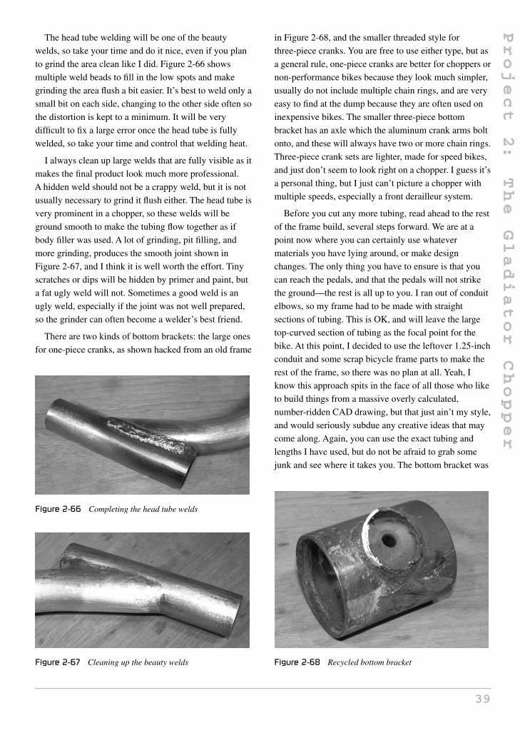
Project
2:
The
Gladiator
Chopper
The head tube welding will be one of the beauty
welds, so take your time and do it nice, even if you plan
to grind the area clean like I did. Figure 2-66 shows
multiple weld beads to fill in the low spots and make
grinding the area flush a bit easier. It’s best to weld only a
small bit on each side, changing to the other side often so
the distortion is kept to a minimum. It will be very
difficult to fix a large error once the head tube is fully
welded, so take your time and control that welding heat.
I always clean up large welds that are fully visible as it
makes the final product look much more professional.
A hidden weld should not be a crappy weld, but it is not
usually necessary to grind it flush either. The head tube is
very prominent in a chopper, so these welds will be
ground smooth to make the tubing flow together as if
body filler was used. A lot of grinding, pit filling, and
more grinding, produces the smooth joint shown in
Figure 2-67, and I think it is well worth the effort. Tiny
scratches or dips will be hidden by primer and paint, but
a fat ugly weld will not. Sometimes a good weld is an
ugly weld, especially if the joint was not well prepared,
so the grinder can often become a welder’s best friend.
There are two kinds of bottom brackets: the large ones
for one-piece cranks, as shown hacked from an old frame
Figure 2-66 Completing the head tube welds
Figure 2-67 Cleaning up the beauty welds
in Figure 2-68, and the smaller threaded style for
three-piece cranks. You are free to use either type, but as
a general rule, one-piece cranks are better for choppers or
non-performance bikes because they look much simpler,
usually do not include multiple chain rings, and are very
easy to find at the dump because they are often used on
inexpensive bikes. The smaller three-piece bottom
bracket has an axle which the aluminum crank arms bolt
onto, and these will always have two or more chain rings.
Three-piece crank sets are lighter, made for speed bikes,
and just don’t seem to look right on a chopper. I guess it’s
a personal thing, but I just can’t picture a chopper with
multiple speeds, especially a front derailleur system.
Before you cut any more tubing, read ahead to the rest
of the frame build, several steps forward. We are at a
point now where you can certainly use whatever
materials you have lying around, or make design
changes. The only thing you have to ensure is that you
can reach the pedals, and that the pedals will not strike
the ground—the rest is all up to you. I ran out of conduit
elbows, so my frame had to be made with straight
sections of tubing. This is OK, and will leave the large
top-curved section of tubing as the focal point for the
bike. At this point, I decided to use the leftover 1.25-inch
conduit and some scrap bicycle frame parts to make the
rest of the frame, so there was no plan at all. Yeah, I
know this approach spits in the face of all those who like
to build things from a massive overly calculated,
number-ridden CAD drawing, but that just ain’t my style,
and would seriously subdue any creative ideas that may
come along. Again, you can use the exact tubing and
lengths I have used, but do not be afraid to grab some
junk and see where it takes you. The bottom bracket was
Figure 2-68 Recycled bottom bracket
39

Project
2:
The
Gladiator
Chopper
welded to a 10-inch length of 1.25-inch conduit, as
shown in Figure 2-69. I chose this length because it was
lying on my floor, ready to be tripped over. The conduit
is ground to conform to the bottom bracket shell and then
tack welded at the top and bottom so alignment could be
checked.
It’s important to ensure the bottom bracket is at
90 degrees to the tube holding it, so that the chain is
aligned with the rings at the front and rear of the vehicle.
A good way to check alignment before welding the entire
joint is by installing the cranks, and making sure the arms
are parallel with the tube. Once checked, complete the
entire weld as shown in Figure 2-70, starting with the top
and bottom of the joint.
Like I said earlier in this section, there was no official
plan here, just a pile of scrap tubing on the floor and the
knowledge of where that bottom bracket needed to be, so
that I could reach the pedals and the pedals had at least
6 inches of clearance from the ground. The tube running
from the head tube to the bottom bracket is called the
Figure 2-69 Installing the bottom bracket
Figure 2-70 Bottom bracket welding completed
“down tube.” It became 18 inches in length in order to
put the bottom bracket where it needed to be, which was
32 inches from where my butt would be on the frame,
and 12 inches off the ground. To figure this out, I sat on
the temporary seat and had a helper measure the distance
from the back of my butt to the bottom of my foot.
Subtract the length of the crank arm, and you now know
where to put the bottom bracket. See why there are no
magic numbers? It’s a vehicle built to fit the rider. The
other small tube shown in Figure 2-71 can be called the
seat tube, and its job is to triangulate the frame for
strength. Honestly, it would not be a problem if it was
omitted altogether, but I think it looks good on a frame.
For reference, this tube is a bit of scrap 1-inch conduit,
approximately 9 inches in length. The length of this tube
was chosen by what was needed to make the lower tube
parallel to the ground.
The frame is almost complete, but at this stage is not
ready for the street. The bottom bracket must continue to
the rear of the frame, in order to create a fully
triangulated frame that will resist bending and become
highly rigid. The thin bicycle scrap tubing shown in
Figure 2-72 might not look like much, and you could
probably bend the thinner tubes by hand, but when added
to the current frame, will strengthen it at least 10 times
more than it is now. Although the Gladiator is a far cry
from a standard bicycle, the frame is still a basic
diamond shape. If you take a single tube away from such
a frame, it will go from being able to support 400 pounds
to collapsing under the weight of a small child. To add
stiffness to the current frame, we must join the two rear
corners to the open tube at the base to create a basic
diamond shape throughout the frame. A dip into my
Figure 2-71 Chaos becomes order
40

Project
2:
The
Gladiator
Chopper
Figure 2-72 Front control arms
scrap pile revealed another set of bent fork legs and a
seat stay from an old mountain bike. Yep, that would
work.
I like working with random bike scrap to make
something unique. Often, you can join two bits of tubing
and then hide the welds to form something that looks
completely alien, hiding any signs of its original life.
When I tell people that the Gladiator was built from only
the most common bicycle parts available, using only a
welder and grinder, they often don’t believe me, so I give
them a tour by pointing at the parts. See that? Those are
washers, not machined hubs, and that’s more conduit
from the hardware store. Oh, and there is a pair of forks
joined to some other frame parts. Personally, I get a
massive sense of pride from seeing someone’s jaw drop,
not only by the look of the final bike, but due to its
origins as rusty throwaway scrap. Not much pride in
dropping a few thousand bucks at the local machine shop
so they can build you a bike, if you ask me!
Anyhow, Figure 2-73 shows some more metal fusion
surgery, done by welding and careful grinding to join the
fork legs to the frame tubing. I liked the tapered look of
the tubing, and the nice curves in the fork legs, which is
why I decided to use them. What do you have lying
around the shop? Old bed frames, tables, chairs—they
all work.
Figure 2-73 More tubing fusion
Figure 2-74 shows how the bits of scrap tubing join
the rear of the frame to the front section, creating a much
stiffer frame. Before the two tubes were added, the frame
might have withstood a 150-pound rider, but the
weakness would be just behind the curve at the top of the
frame, and it would have been a very flexible frame. I’m
sure that the front forks would be the weakest link,
although nothing besides a head-on collision with a wall
or truck would be a problem. Now you can see that
spontaneity can really add to your craft, and the results
are often better than you would have imagined. I really
like the way the frame turned out, even though the lower
half was built using only the parts I was too lazy to clean
off the garage floor. Having a large scrap pile is better
than any expensive tool!
You might have realized that the front forks are not
complete yet, because the two fork support tubes would
not be strong enough to carry the weight of the loaded
bike. All triple-tree forks have a bottom and a top
support, but since we extended the forks past the top of
the fork threads, the traditional top clamp design is no
longer an option. To secure the upper part of the forks to
the top of the fork stem, this simple clamp system does a
great job, and is made by cutting the clamp from a
standard bicycle gooseneck and replacing it with these
two small pieces of flat bar. Figure 2-75 shows the
gooseneck after removing the clamp, as well as the two
bits of flat bar that will connect to the front fork tubes
using a pair of screws.
Figure 2-76 shows the completed fork mounting
system, which is built by dropping the gooseneck stem
into the top of the fork stem to figure out how long and at
what angle these two bits of flat bar need to be cut. As
you will see in the next photo, the holes drilled at the
Figure 2-74 The frame is now complete
41

Project
2:
The
Gladiator
Chopper
Figure 2-75 The top of the fork mounting system
Figure 2-76 Fork mounting part completed
ends of the flat bar allow a woodscrew to hold the unit to
the fork legs.
With the top clamp holding the fork legs in position, as
shown in Figure 2-77, your forks are now ready to take
the full weight of the loaded chopper. You can now safely
handle the vehicle or sit on the frame without any worry
of bending any part of the frame or forks, since they are
completely rigid now. Of course, there is a bit more work
Figure 2-77 Front forks completed
to do before you can cruise down the center of the road
like you own it.
When building a chopper using car parts, you are
presented with several challenges in the transmission and
brakes department, since bolt-on bicycle parts will not
work. A trike also adds another dimension to the problem
because you have to find a way to drive one of the rear
wheels from a standard bicycle crank set. I decided to
solve both problems with one simple part which I call the
“remote coaster hub.” A coaster hub is a single speed hub
that allows the pilot to pedal backwards to activate the
brakes. This design was widely used before the derailleur
on most bikes, and is still commonly used on most
children’s bikes and some beach cruiser-style adult bikes.
I liked the coaster brake idea because it would eliminate
all ugly looking cables and levers from the bike,
something that would look out of place on a chopper. The
problem was how to transfer the motion of the rear-drive
axle directly to the coaster hub, so it would act as a brake
and still allow the pilot to stop pedaling and coast.
The answer was actually pretty simple—weld a
sprocket to the coaster shell, then run a chain to another
sprocket on the rear-drive axle. This way the coaster hub
would appear to be directly connected to the rear wheel,
so it would act as if it were doing its usual job. To create
this transmission system, you will need two steel
sprockets of approximately equal size (number of teeth)
and a steel coaster hub. All parts shown in Figure 2-78
came from discarded children’s bikes—the ones with
really tiny wheels. Often, these bikes have perfectly good
coaster hubs installed in tine wheels with 16 spokes, so
they are perfect for salvage and have probably had
almost no wear on them. The two 28-tooth sprockets are
also from old kids’ bikes, taken from the crank set by
Figure 2-78 Mid-drive transmission parts
42
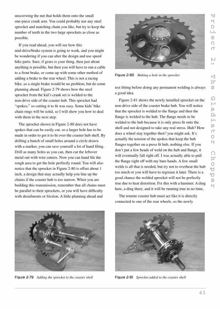
Project
2:
The
Gladiator
Chopper
unscrewing the nut that holds them onto the small
one-piece crank arm. You could probably use any steel
sprocket and matching chain you like, but try to keep the
number of teeth in the two large sprockets as close as
possible.
If you read ahead, you will see how this
mid-drive/brake system is going to work, and you might
be wondering if you can alter the design and use speed
bike parts. Sure, if gears is your thing, then just about
anything is possible, but then you will have to run a cable
to a front brake, or come up with some other method of
adding a brake to the rear wheel. This is not a racing
bike, so a single brake would be no problem, but do some
planning ahead. Figure 2-79 shows how the steel
sprocket from the kid’s crank set is welded to the
non-drive side of the coaster hub. This sprocket had
“spokes,” so cutting it to fit was easy. Some kids’ bike
chain rings will be solid, so I will show you how to deal
with them in the next step.
The sprocket shown in Figure 2-80 does not have
spokes that can be easily cut, so a larger hole has to be
made in order to get it to fit over the coaster hub shell. By
drilling a bunch of small holes around a circle drawn
with a marker, you can save yourself a lot of hand filing.
Drill as many holes as you can, then cut the leftover
metal out with wire cutters. Now you can hand file the
rough area to get the hole perfectly round. You will also
notice that the sprocket in Figure 2-80 is offset about 1
inch, a design that may actually help you line up the
chains if the coaster hub is too narrow. When you are
building this transmission, remember that all chains must
be parallel to their sprockets, or you will have difficulty
with derailments or friction. A little planning ahead and
Figure 2-79 Adding the sprocket to the coaster shell
Figure 2-80 Making a hole in the sprocket
test fitting before doing any permanent welding is always
a good idea.
Figure 2-81 shows the newly installed sprocket on the
non-drive side of the coaster brake hub. You will notice
that the sprocket is welded to the flange and then the
flange is welded to the hub. The flange needs to be
welded to the hub because it is only press fit onto the
shell and not designed to take any real stress. Huh? How
does a wheel stay together then? you might ask. It’s
actually the tension of the spokes that keep the hub
flanges together on a press fit hub, nothing else. If you
don’t put a few beads of weld on the hub and flange, it
will eventually fall right off. I was actually able to pull
the flange right off with my bare hands. A few small
welds is all that is needed, but try not to overheat the hub
too much or you will have to regrease it later. There is a
good chance the welded sprocket will not be perfectly
true due to heat distortion. Fix this with a hammer. A ding
here, a ding there, and it will be running true in no time.
The remote coaster hub must act like it is directly
connected to one of the rear wheels, so the newly
Figure 2-81 Sprocket added to the coaster shell
43

Project
2:
The
Gladiator
Chopper
installed coaster hub sprocket will connect to a fixed rear
axle sprocket of the same size. Now, whatever the
rear-drive wheel does, that is what the coaster hub will
also do, making it seem like the rear wheel and coaster
hub are one piece. To get the sprocket connected to the
rear-drive wheel (the left wheel), we need to fix it to the
left axle. This is done by welding the sprocket to a small
piece of round tube that just happens to fit snugly over
the 3/4-inch axle, as shown in Figure 2-82. Where do you
find such a tube? Try the tubing from a mountain bicycle
handlebar, as it is the perfect fit. A 2-inch segment of the
handlebar tubing should be plenty to mount the sprocket
and the bolt that will hold it to the axle.
The completed rear-drive axle sprocket is shown in
Figure 2-83, ready to mount to the left axle. When you
install your crank set and mid-drive transmission, you
will see that the left axle is the only logical place where
you can mount this sprocket in order to get the two
chains to line up. The two bolts will secure the sprocket
to the axle, but do not drill out the axle until you know
your chains are all going to line up. Some adjustments
Figure 2-82 The rear axle sprocket
Figure 2-83 Rear-drive axle sprocket completed
may be needed later. Also notice that most of the axle
mounting tube is on one side of the sprocket. This is done
because the sprocket will need to be as close to the
bearing as possible when you get those chains lined up.
This will become obvious as you progress.
As mentioned earlier, the rear-drive sprocket is placed
on the left axle so that it is as close to the inner bearing as
possible without any sprocket or chain rubbing. The
coaster hub is just wide enough to deliver the chain from
the crank set on the right side of the bike to the left axle
at the rear of the bike, which is why this is done. The
coaster drive sprocket and crank ring always have to be
on the right side of the bike, or the brake will not
function. Figure 2-84 shows the drive sprocket bolted to
the axle with minimal clearance between its face and the
inner bearing. I would advise waiting until all of the
chains are installed before you drill the axle holes, just in
case you need to make some adjustments or alterations.
When you mess around with bicycle parts, there is one
tool that is well worth the 10 bucks you will shell out for
it—the chain tool. In the old days, I would bash chains
apart by using a punch, or a finishing nail to bang out the
link pins, but after turning so many fingernails blue, I
decided to invest in the chain tool. Seriously dude,
putting chains together is so easy with the chain tool that
it is baffling how I got by without it. Figure 2-85 shows
the chain tool and a ball of chain about to be made into
the dual chains needed to propel the Gladiator.
Figure 2-86 shows how the remote coaster hub
transfers the drive across the hub shell to the rear left
axle. It makes no difference at all where you place the
mid drive, or how you attach it to the frame, as long as
the chains line up and they do not rub on any part of the
frame. I cut a pair of rear dropouts from an old speed
Figure 2-84 Rear-drive sprocket installed
44

Project
2:
The
Gladiator
Chopper
Figure 2-85 Get one of these tools!
Figure 2-86 Installing the mid drive
bike, bolted them onto the coaster hub, then cut and
installed two chains with the least amount of slack
possible. From here, I could mess around with areas to
weld the two dropouts, in order to permanently mount
the mid-drive hub. I found that placing it in the middle of
the frame, as shown in Figure 2-86, was optimal, which
is why I ended up calling it the mid-drive hub. You could
hide it directly under the rear sprocket at the far rear of
the bike, or move it to the front of the bike if you wanted,
as long as the chains are happy. When I did find a place
that kept the chain slack to a minimum and had no chain
interference, I tack welded the two dropouts directly in
place while holding on to the hub. This system works
well, but be careful not to hit the chain or sprocket with
the welding stinger. In Figure 2-86, the two dropouts
have just been tack welded to the frame. It took a bit of
fiddling around to get the two chains the right size, but
that’s why you have the chain tool. Also, that arm
sticking out of the non-drive side of the coaster hub must
be secured to the frame for the brakes to work. If you do
not secure the arm, the entire hub will twist around the
axle, loosen all the bearings, derail the chain, and then
seize up solid on you. Don’t forget about this before your
first test run, or you will look like a dork as you push
your chopper home.
Do you want to lie back in a relaxed, recumbent
position, drinking a coffee as you cruise down the street,
or hang on for dear life, crunched over in a most
uncomfortable position? Yes, both of these seating
positions are totally cool with the chopper crowd, so it’s
up to you which one you choose, or some combination of
the two. Because a trike is a stable vehicle that will allow
you to stop without putting a foot down, I went for the
relaxed seating position, which would also include a nice,
tall backrest. Because I am a high ranking member of
“Club Laziness,” this laidback position was my choice.
I planned to sit back, and then let the handlebars come to
me, but if you already have a firm plan for the handlebars,
you may want to leave the seat until the end. From here
on, you can finish the chopper in any order you like; the
only thing you have to be mindful of is how far you need
to be away from those pedals for a comfortable ride.
Figure 2-87 shows my randomly planned high-back
seat, made by slicing and dicing some 3/4-inch thin
square tubing to conform to my back as I sat on the
temporary seating. The only advice I have is to not make
a headrest, or at least a headrest that is always on the
back of your head. This may seem like a good idea at
first, but you will find it highly annoying as the bumps
from the rear wheels are amplified and sent to the back of
your head. A neck rest is OK, but not a headrest, unless it
is simply there for looks.
Figure 2-87 Seating is a personal touch
45

Project
2:
The
Gladiator
Chopper
After making an entire chopper from inexpensive raw
materials, I wasn’t about to spew up a hundred bucks on
some fancy chrome ape hangers that would probably be
too flimsy or short for the bike anyhow, so I decided to
make my own. It was one of my design goals to not have
any chrome on my chopper since this is a worn-out
tradition, so making the handlebars would be fine, as
they would be painted anyhow. That 3/4-inch EMT
conduit is exactly the same diameter as bicycle handlebar
tubing, and it was a bit heavier, so welding parts together
would be a snap. Figure 2-88 shows two more factory
elbows and some lengths of 3/4-inch conduit to make my
ultra stretch handlebars.
More welding and more grinding is all you need to
create seamless joints between two pieces of metal, as
shown in Figure 2-89. The two handlebar halves are
nothing more than 12 inches of conduit welded to a
factory elbow, but they are perfectly suited for this bike,
so they are better than anything that can be purchased, in
my opinion.
I think it’s cool to have the handlebars come directly
from the front forks, like they are on Figure 2-90. This
system is strong, simple, and screams out customization.
Figure 2-88 Ape hangers the poor man’s way
Figure 2-89 Weld and grind to hide seams
Figure 2-90 A unique handlebar mounting method
As you can see, the handlebars are quite long due to my
relaxed seating plan, so it would have been difficult to
find a bicycle handlebar to reach. How about hacking
some furniture tubing into rounded handlebars? Yes, look
in the most unlikely places to find your needed materials.
This chopper is so close to getting painted that I can
already smell the fumes! It’s almost painful to spend time
capping the ends of the tubes and cleaning up any messy
welds, but this is where true craftsmanship shines. I took
all of the large tube ends (forks and frame) down at a
45-degree angle, then capped them off with some oblong
sheet metal discs, as shown in Figure 2-91. Sure, it took a
while to weld and grind, then reweld and grind again
until all five caps were perfect, but damn did they look
good afterwards. If you plan to add the bells and
whistles, do it now before painting.
The capping of the five open tubes took longer than
the building of the rear wheels, but the results were worth
the effort. You can’t purchase tubing like this, so you
really have a true custom. The handlebar welds and most
other welds that were visible were all cleaned up and
Figure 2-91 Don’t forget the trimmings!
46

Project
2:
The
Gladiator
Chopper
ground for appearance as well since the next step was
primer. Take a few sheets of emery cloth and go to town
on the frame, cleaning up the metal and burnt paint as
much as you can so the primer coat goes on smooth. Old
paint does not have to be totally removed, just sanded
smooth so it blends into the bare metal at the edges. I use
only spray paint from a can, but the results can be very
good if you take your time and apply the paint according
to the directions, which is usually in short strokes held at
8 to 10 inches from the metal. I hang my frames from a
clothesline in the backyard when I paint, and usually
apply primer in two coats to avoid any runs or streaks. If
you are new to painting, ask a fellow builder who knows
how to wield a spray bomb, or search the Internet for a
spray can painting tutorial, as there are many good
sources of information.
The rear rims are metallic blue, so what would be the
point of throwing on a front chrome rim? I had nothing
better to do while the primer was drying overnight, so I
pulled out all of the spokes in this old steel mountain bike
front rim so I could paint it to match the rear rims.Yes,
you could try to tape up all the spokes to paint the rim,
but that would be a tedious job that would probably leave
you with a rim full of paint runs, and that would not add
to your skills. As shown in Figure 2-93, I removed the 36
spokes by loosening them two turns each around the
entire rim, so they would then come out by hand turning
the nipples the rest of the way. Now, I could properly
sand the rim as well as the hub to give them the same
metallic blue paint job that I gave the rear rims.
Building a bicycle rim is really not as hard as some
would have you think, and since you already have all the
spokes and can see how they were put in, you only have
Figure 2-92 Capped tubing
Figure 2-93 Matching the front rim to the rear
Figure 2-94 Painted and curing
to copy what was already done. These big old steel rims
are easy to paint, easy to spoke, and can be trued up
fairly easily, so don’t be afraid to go all the way.
The parts shown in Figure 2-94 are freshly painted and
need to cure for a few days to avoid easily scratching the
paint. I know this is the most difficult thing in the world
to do, but resist the urge to assemble the chopper while
the paint is still tacky. Hey, you still need to build a seat,
so let’s move on to that for the rest of the day. Step away
from those parts! Oh, and if you want to see what color
the Gladiator is, then you will have to visit
AtomicZombie.com to see it in full living color.
I mentioned earlier that I found that two springs
seemed a little spongy for my liking, so I added four
springs to the suspension system (Figure 2-95). Here is a
close-up shot of how I joined the spring to the pivoting
fork leg, in case you want to use this design as well. The
four springs are much stiffer, and let me hop the front
wheel up and down off the ground while I am parked at a
red light, just like those crazy low riders. This suspension
system is actually quite smooth and functional.
47

Project
2:
The
Gladiator
Chopper
Figure 2-95 Dual spring detail
If you do not have a ready made seat for your chop,
then grab that jigsaw and some scrap wood. It is not
difficult to fashion your own crude seat. I took two bits of
half-inch plywood, one 10 x 10 inch piece, and a 10 x 14
inch piece, then rounded the ends off using a dinner
plate. The three bits of flat bar shown on the seat boards
in Figure 2-96 are drilled for a few woodscrews, then
bent to whatever angle you want to hold the seat boards
together. You may also want to hack up an office chair, or
find a fishing boat seat to modify. The possibilities for
making a chopper seat are as endless as the number of
wild customs there are.
I had some random bits of foam padding left over from
a few other bike builds, so I used up the scraps shown in
Figure 2-97 to pad the seat. The seat base is made from a
1.5-inch thick bit of high density foam and the back is
made from rigid 1-inch foam. Stiff white foam used to
pack appliances also works great for seats, but do avoid
the really spongy stuff you might find in furniture
cushions, as it’s way too soft. The foam is rough cut and
then glued to the seat board using spray adhesive.
Figure 2-96 Making a seat
Figure 2-97 Choosing seat padding
Once the rough cut foam is glued to the seat boards, I
like to take the grinder and run it along the board
perimeter to make a perfect foam cut, as shown in
Figure 2-98. Be careful when using a grinder on foam, as
it may snag and throw the seat away from you if you try
to press too hard when grinding away the foam. You
could also trim with a long sharp knife, but you know I
love my grinder, and would probably use it to shave if
my electric razor ever burned out.
Figure 2-99 shows the seat getting a nice covering of
black spandex material. You can cover your seats in
anything you like, but try to find something that will not
Figure 2-98 Cutting the foam edges
48
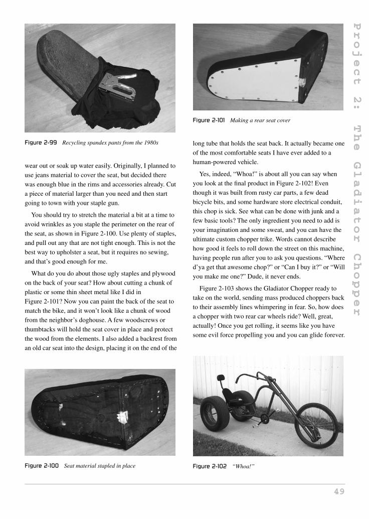
Project
2:
The
Gladiator
Chopper
Figure 2-99 Recycling spandex pants from the 1980s
wear out or soak up water easily. Originally, I planned to
use jeans material to cover the seat, but decided there
was enough blue in the rims and accessories already. Cut
a piece of material larger than you need and then start
going to town with your staple gun.
You should try to stretch the material a bit at a time to
avoid wrinkles as you staple the perimeter on the rear of
the seat, as shown in Figure 2-100. Use plenty of staples,
and pull out any that are not tight enough. This is not the
best way to upholster a seat, but it requires no sewing,
and that’s good enough for me.
What do you do about those ugly staples and plywood
on the back of your seat? How about cutting a chunk of
plastic or some thin sheet metal like I did in
Figure 2-101? Now you can paint the back of the seat to
match the bike, and it won’t look like a chunk of wood
from the neighbor’s doghouse. A few woodscrews or
thumbtacks will hold the seat cover in place and protect
the wood from the elements. I also added a backrest from
an old car seat into the design, placing it on the end of the
Figure 2-100 Seat material stapled in place
Figure 2-101 Making a rear seat cover
long tube that holds the seat back. It actually became one
of the most comfortable seats I have ever added to a
human-powered vehicle.
Yes, indeed, “Whoa!” is about all you can say when
you look at the final product in Figure 2-102! Even
though it was built from rusty car parts, a few dead
bicycle bits, and some hardware store electrical conduit,
this chop is sick. See what can be done with junk and a
few basic tools? The only ingredient you need to add is
your imagination and some sweat, and you can have the
ultimate custom chopper trike. Words cannot describe
how good it feels to roll down the street on this machine,
having people run after you to ask you questions. “Where
d’ya get that awesome chop?” or “Can I buy it?” or “Will
you make me one?” Dude, it never ends.
Figure 2-103 shows the Gladiator Chopper ready to
take on the world, sending mass produced choppers back
to their assembly lines whimpering in fear. So, how does
a chopper with two rear car wheels ride? Well, great,
actually! Once you get rolling, it seems like you have
some evil force propelling you and you can glide forever.
Figure 2-102 “Whoa!”
49

Project
2:
The
Gladiator
Chopper
Figure 2-103 “Yes, I do own the road”
Sure, it takes a little muscle to get up to speed, but if you
were afraid of a little exercise, you wouldn’t be building
a human-powered vehicle now, would you? Of course,
with the sheer amount of attention this ride commands,
it’s tough to get more than half a block before you are
hijacked by someone needing a closer look. What a
showpiece!
On my first long test run, I took the Gladiator for a
10-mile ride. Everything worked perfectly, and the
suspension was remarkably effective over small potholes
and bumps. The seat was very comfortable, the steering
was good, and the brakes had enough power for all but
the really steep hills, which I avoided anyhow. This was
one of the first times I have rolled out of the garage and
not come home for several hours without needing some
type of small tweak or minor modification. The Gladiator
really rode as good as it looked right from the second the
paint was dry. Sha-weet! Again, I am posing it up on the
chopper in Figure 2-104.
Although I try not to abuse something I spend so much
time building, it is hard to resist pounding the front wheel
up and down, so it bounces right off the ground when I
am waiting for a light to change or at a stop sign. The
springer fork can really get bouncing pretty high, and it
almost looks like there are hydraulics in the forks, an
idea that I may actively pursue when it comes time for
modifications. Yes, no custom is ever complete! Look at
that sick profile in Figure 2-105.
It’s easy to forget about all the healthy exercise you are
getting when you are rolling around on such a cool
machine (Figure 2-106). After three hours, your legs feel
like they have done some real work, but that’s not so bad,
as it just means you will be alive longer to enjoy your
newfound hobby! I thought of adding a small electric
Figure 2-104 Words cannot describe…
Figure 2-105 Rides like a dream
Figure 2-106 Relaxing after a long cruise
motor to the Gladiator, but it’s just so crazy to have such
a full-sized chopper under only human power, as if
throwing the bird to all those who make a huge pile of
noise with their petrol burning engines and spit oils all
over the place! Yes, we take rebellion one step further by
50

Project
3:
Old
Skool
Attitude
rebelling against the mainstream rebels. After all, riding
a chopper is all about being different!
Well, I sure hope you enjoyed this project, as I sure
did! It’s almost painful to put the Gladiator away at the
end of a ride, but my legs can only take me so far, and I
know the chopper will never give up. This project is
proof that you do not need to spend a lot of money,
acquire high-tech tools, or learn any elite skills in order
to make your mark in the custom community. I look
forward to seeing your version of the Gladiator Chopper,
and hope you will drop by our website to share your
photos, ideas, and stories of pain and glory with the rest
of the avid garage hackers. Well, I am off to hit the wide
open road on the ultimate chopper trike shown in Figure
2-107, so as the gladiators would say: live free, fight
hard! The next project isn’t as labor intensive as the
Gladiator, but is another cool chopper with an “old skool”
design.
Figure 2-107 Until next time
Project 3: Old Skool Attitude
The Old Skool Attitude chopper brings back the golden
age of chopper building, where most bicycles had only a
single speed, one brake, balloon tires, and nice flowing
lines in the frame. Your daddy would remember the days
when he and his buddies would take that old bicycle,
extend the forks by hammering another pair end to end,
replace the front wheel with a smaller one, and then
strip all unnecessary parts from the frame. Those
builders who had access to a welder may even go as
far as modifying the frame or forks to adjust the rake,
which is what I plan to do here. The fun thing about
this project is that all of the parts are true to the era,
right down to the 1970s exercise bike that I used for
parts. Well then, crank up the Black Sabbath, grab a cold
drink from the “Harvest Gold” colored refrigerator,
and let’s travel back in time for some Old Skool
chopping!
Figure 3-1 shows the vintage 1970s single-speed
frame that I found at the dump one day while scavenging
for parts. I was just a young “whippersnapper” when
these bikes were on the road, but I do remember seeing
them chopped and modified, ridden by garage hackers of
the day. I thought it would be cool to salvage this old
frame from the mud and give it the life it always wanted,
keeping true to the style of the era from whence it came.
I had an old 1970s exercise bicycle sitting in the back of
my garage, as well as a banana seat, an old single-speed
wheel, and a vintage bicycle light, so this project was
certainly possible.
I planned to add longer forks to the chopper, but
did not want it to lean back too much, so a simple
frame extension would be necessary in order to
increase the rake and length of the frame, which
51Copyright © 2008 by The McGraw-Hill Companies, Inc. Click here for terms of use.

Project
3:
Old
Skool
Attitude
Figure 3-1 A vintage 1970s single-speed frame
would keep the bottom bracket roughly at the same
height to the ground. As shown in Figure 3-2, the
original head tube was removed and two pieces of
conduit, equal in diameter to the original frame tuber,
were fit in place. The original head tube could not be
reused due to the lugged construction, which leaves
huge holes in the head tube, and contaminates the
joint with brazing filler. Another head tube from
some scrap frame was used to replace the original
head tube.
Figure 3-3 shows the top tube extension being tack
welded to the frame. This 8-inch long piece of conduit
has the same diameter as the original frame tubing, so it
Figure 3-2 A simple frame modification
Figure 3-3 Installing the top tube extension
would be easy to seamlessly integrate it by grinding
away the weld material. Head tube angle was also
increased to allow the new forks to have quite a bit of
rake, so that the frame would not be lifted at the front,
creating a skyscraper style chopper. When doing these
ad-hoc frame modifications, it is a good idea to place the
parts and wheels on the ground to make sure your final
product will have the angles and dimensions you are
after. Bottom bracket height is another matter of concern,
as you don’t want your pedals to hit the ground around
corners.
The first extension tube was completely welded at the
top tube joint, as well as the head tube joint, as shown in
Figure 3-4. The head tube was checked for vertical
alignment with the seat tube just after the first few tack
welds were made.
To make the final product look like it was born to be a
chopper, the frame welds are ground completely flush
and then carefully cleaned with a flat file. The resulting
tube extension, as shown in Figure 3-5, is completely
seamless. When making a seamless joint, rough grind the
Figure 3-4 First tube completely welded
Figure 3-5 Cleaning up the welded area
52

Project
3:
Old
Skool
Attitude
weld material with a grinder disc, being careful not to
create a low spot, and then finish up with a hand file, so
you do not accidentally take away any excess material.
The seamless joint will be just as strong as the original
weld, as long as your penetration and welding technique
are adequate. Chances are that you will have to fill in a
few tiny holes and the grind a little more, but it is all for
the love of the craft.
The missing section of down tube will be filled in with
another piece of electrical conduit: this time a section of
factory elbow. As shown in Figure 3-6, the elbow is cut
so that the curve joins the original down tube as a butt
joint and then curves up to meet the head tube. If you
have a tube bender, you could also make your own
curved extension tube.
Figure 3-7 shows the completed frame modifications
after cleaning up the down tube welds at the seam. Once
painted, there will be no detectable seam where the frame
Figure 3-6 Adding the down tube extension
Figure 3-7 Frame modifications completed
was cut and welded, making the final product look very
professional. I’ll bet your dad never had a chopper frame
of this quality!
To keep in with my silly idea of only adding vintage
parts to the Old Skool chopper, I dug out this vintage
1970s exercise bike from the huge pile of scrap at the
back of my garage. I could almost hear ABBA songs
playing in the background, as I gave the cranks one last
spin before heating up the zip disc for total annihilation
of the unit. I decided to use the handlebars of the exercise
bike as chopper forks, integrating the actual handlebars
and fork legs as one smooth flowing line. Those massive
cranks would also fit the new chopper perfectly, as they
were also the correct style for this project.
The two front tubes that form the handlebars and front
stand on the old exercise bike were hacked from the
frame, as shown in Figure 3-9. I also cut the legs off
some really old kids’ bike forks so I could weld them to
the end of the new forks, creating that nice tapered look
that all forks had back in the day. Also shown in
Figure 3-9 is a fork stem that will fit into the chopper
frame’s head tube, allowing me to create the new
long forks.
To create the new flowing front forks, the two
amputated fork legs were bolted onto the front wheel
axle and then tack welded to the exercise bike tubing.
Figure 3-10 gives you a clear image of how I planned to
integrate the curved tubing into one continually flowing
Figure 3-8 Official vintage exercise gear
53

Project
3:
Old
Skool
Attitude
Figure 3-9 These parts will become the new forks
Figure 3-10 Using the front wheel as a guide
handlebar and fork unit. The front wheel is used as a
guide to make sure each fork leg and handlebar half has
the same shape and angle.
To join the new long forks to the chopper, a fork stem
would need to be connected to both tubes in order to
create a useable pair of forks. The fork stem and two
small tubes shown in Figure 3-11 will be used to
complete the assembly, securing the two fork legs to the
head tube. The two smaller tubes will be welded to the
fork stem at 90 degrees to each other, and are at whatever
Figure 3-11 Adding the fork stem
length is necessary to place the fork legs parallel to each
other, as will soon be shown.
The two small tubes are welded to the base of the fork
stem, as shown in Figure 3-12, so there is a 90-degree
angle between them. Because the front wheel is being
used as a guide to keep the two fork legs parallel to each
other, it is easy to figure out how long each of the two
small tubes needs to be. The ends of both tubes are
ground out to conform to the fork legs, making the joint
easy to weld.
Figure 3-13 shows how the new fork stem joins
the two fork legs together, so that they run parallel to
each other once held in place by the front wheel axle.
The position of the fork stem will determine the
length of the forks and the height of the handlebars
in relationship to the frame. I decided to keep the
forks as long as possible, placing the handlebars
very low for a “low and lean” look. The fork stem
should also run perfectly parallel to each fork leg,
Figure 3-12 Fork tubing welded
Figure 3-13 Installing the fork stem
54

Project
3:
Old
Skool
Attitude
in order to keep the forks aligned with the rest of the
frame.
The new forks can now be installed, as shown
in Figure 3-14, although it is not a good idea to put
any weight on them just yet. The two small tubes
that connect the fork legs to the fork stem are not
strong enough to take any real weight, so some extra
support will have to be added between the top of the
fork stem and the fork legs. This dual support
system is often referred to as a triple-tree fork. Also,
notice how low my handlebars are in relation to the rest
of the frame. The rider will have to hunch over to
reach the handlebars, but whoever said a chopper
should be comfortable? It’s about attitude, not comfort!
The top of the fork stem needs to have some kind of
support, in order to keep the two lower tubes from
bending once weight is on the frame. I found two
reflector mounting brackets, as shown in Figure 3-15,
which, when bent the appropriate way, would fit
perfectly between the top of the fork stem and the fork
legs, assigning the needed support. You could also make
Figure 3-14 New forks installed
Figure 3-15 More recycling of parts
a triangular plate with a hole for the fork stem to do this
job as well.
The two reflector brackets are shown installed on the
fork stem in Figure 3-16, adding the needed support for
the fork legs. A small hole will be drilled in each fork leg,
so a machine screw can secure the brackets to the fork
legs, giving the entire fork assembly much greater
strength. Now the fork legs can take the weight of a rider
safely.
Well, that’s pretty much it. To keep true to the era, I
added a banana seat, single-speed coaster brake rear
wheel, vintage bicycle light, and the crank set from the
old exercise bike. Oh, and most choppers from back then
had a front wheel that was much smaller than the rear, so
I added a 20-inch front wheel. Figure 3-17 shows the Old
Skool chopper before painting.
Although you can’t see the colors in Figure 3-18, the
frame was painted a nice faded green, and the forks were
sprayed using what is referred to as Gypsy chrome, a
silver paint. Notice how the frame shows no signs of
Figure 3-16 Top support brackets installed
Figure 3-17 Staying true to the era
55

Project
3:
Old
Skool
Attitude
Figure 3-18 Faded green and Gypsy chrome
Figure 3-19 Just like your old man used to ride
modification due to the careful cleaning of all
the joints.
The finished Old Skool chopper is shown in
Figure 3-19, complete with a rear balloon tire, and retro
brown handle grips. Since most bicycles of the 1970s had
fenders and a chain guard, chopper builders of the day
Figure 3-20 Bad attitude—Old Skool style
would remove them to be rebellious, which is why this
chopper has neither.
The Old Skool chop actually rode very well,
considering the ultra low handlebars and extended forks.
With that huge balloon tire and coaster brake rear wheel,
you could lock up the wheel, and fishtail like crazy
around the corner, leaving a thick, black trail of rubber
on the road. The wheelie ability of this chopper was
intense, thanks to the banana seat, allowing the rider to
shift the center of gravity over the rear wheel. Just look at
how cool that Old Skool chopper looked—Figure 3-20.
Next time you find a bunch of retro junk at the dump,
bring some attitude back from the past. Hang onto your
welding hats, kids. The next project will appeal to the
young chopper enthusiasts.
56

Project
4:
Whippersnapper
Project 4: Whippersnapper
Here is a chopper for your young whippersnappers. It’s
only fair that the little ones have cool wheels, especially
if you have built yourself a chopper. This simple chop
can be made in an afternoon using an old children’s bike
and a few scrap bits of tubing, twisting a normally
mundane set of wheels into a cool mini chopper that will
be the envy of all young rebels on the block.
These tiny kids’ bikes are so common at the city dump
scrap pile and at yard sales that you could probably go
into business making kids’ choppers! Figure 4-1 shows
Figure 4-1 A typical kids’ bike
one of the dozen or so identical kids’ bikes with 10-inch
wheels that I had in my scrap pile. It should be an easy
job to make a chopper out of this bike, requiring only a
longer set of forks and a few basic frame modifications.
The entire bike was disassembled so all the parts could
be cleaned and checked over for damage. The bike came
apart in minutes, as shown in Figure 4-2, revealing parts
that looked almost brand new once degreased and
cleaned a bit. Since kids’ bikes often have little mileage,
rust will be your only enemy.
The plan was to replace the original forks with a pair
from a full-sized mountain bike, giving that “extendo
fork” chopper look. Of course, simply replacing the front
forks would also make the front end a lot higher, creating
a very difficult-to-ride bike that leans back so much that
it would wheelie instantly. To accommodate a much
longer set of forks, the frame will need some extension
and head tube rake adjustment. To make the head tube
adjustment and stylize the frame, the entire middle
section is cut and removed, as shown in Figure 4-3. The
head tube is then ground clean so it can later be
welded.
The head tube will be placed at a more relaxed angle
and a little further from the seat, so that the young
chopper pilot does not have the handlebars too close to
his or her knees. This modification will also keep the
bottom bracket at the original height, avoiding the
wheelie effect. Figure 4-4 shows the general frame
Figure 4-2 Taking inventory of the parts
57Copyright © 2008 by The McGraw-Hill Companies, Inc. Click here for terms of use.

Project
4:
Whippersnapper
Figure 4-3 Hacking up the frame
Figure 4-4 Using some bent conduit
modification plan, using a bit of scrap bent conduit to
replace the missing center frame tubing. The curved
tube made the frame take on a whole new stylish look.
You can use just about any scrap tubing to make
these mods since the frame will not be under much
stress.
As shown in Figure 4-5, the original head tube will be
reused, so take your grinder and remove the excess frame
tube left over from the cutting. If you plan on replacing
the front forks, make sure that the new head tube matches
the forks you intend to use. Some kids’ bikes are so
cheaply made that the head tube does not even include
Figure 4-5 The original head tube
any bearing hardware, so you may have to replace the
original head tube.
Before you go crazy with the welder, install the wheels
and lay out the frame, as shown in Figure 4-6. You can
ensure that the rake and bottom bracket height are what
you want. The best ride will come from a chopper that is
modified in such a way that the original bottom bracket
height and handlebar position remain the same,
regardless of how long the forks are. As you can see in
Figure 4-6, the rear of the bike is almost at the same
angle that it was originally.
To make the best weld, the tubing should be ground in
such a way that there are few or no gaps in the entire
joint. As shown in Figure 4-7, the new frame tube
conforms to the shape of the bottom bracket, making the
joint much easier to weld.
Figure 4-8 shows the joint between the original frame
tubing and the new length of conduit that will extend the
frame. If you are joining two different sized tubes, it may
help to squeeze the ends of the wider tube flat so there is
no gap.
Figure 4-6 Figuring out frame angles
Figure 4-7 Grinding the tubing for a better weld
58
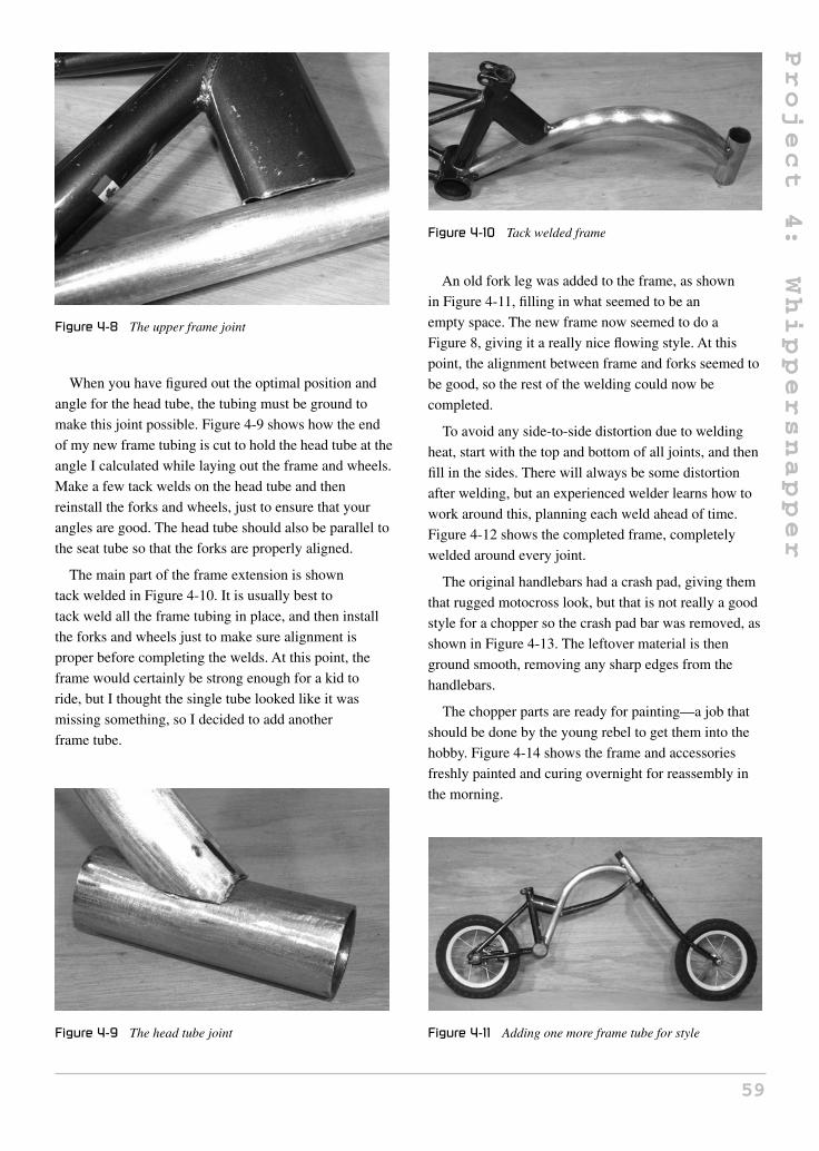
Project
4:
Whippersnapper
Figure 4-8 The upper frame joint
When you have figured out the optimal position and
angle for the head tube, the tubing must be ground to
make this joint possible. Figure 4-9 shows how the end
of my new frame tubing is cut to hold the head tube at the
angle I calculated while laying out the frame and wheels.
Make a few tack welds on the head tube and then
reinstall the forks and wheels, just to ensure that your
angles are good. The head tube should also be parallel to
the seat tube so that the forks are properly aligned.
The main part of the frame extension is shown
tack welded in Figure 4-10. It is usually best to
tack weld all the frame tubing in place, and then install
the forks and wheels just to make sure alignment is
proper before completing the welds. At this point, the
frame would certainly be strong enough for a kid to
ride, but I thought the single tube looked like it was
missing something, so I decided to add another
frame tube.
Figure 4-9 The head tube joint
Figure 4-10 Tack welded frame
An old fork leg was added to the frame, as shown
in Figure 4-11, filling in what seemed to be an
empty space. The new frame now seemed to do a
Figure 8, giving it a really nice flowing style. At this
point, the alignment between frame and forks seemed to
be good, so the rest of the welding could now be
completed.
To avoid any side-to-side distortion due to welding
heat, start with the top and bottom of all joints, and then
fill in the sides. There will always be some distortion
after welding, but an experienced welder learns how to
work around this, planning each weld ahead of time.
Figure 4-12 shows the completed frame, completely
welded around every joint.
The original handlebars had a crash pad, giving them
that rugged motocross look, but that is not really a good
style for a chopper so the crash pad bar was removed, as
shown in Figure 4-13. The leftover material is then
ground smooth, removing any sharp edges from the
handlebars.
The chopper parts are ready for painting—a job that
should be done by the young rebel to get them into the
hobby. Figure 4-14 shows the frame and accessories
freshly painted and curing overnight for reassembly in
the morning.
Figure 4-11 Adding one more frame tube for style
59

Project
4:
Whippersnapper
Figure 4-12 Completing the frame welds
Figure 4-13 Chopperizing the handlebars
Figure 4-14 Wet paint—do not touch
The completed chopper shown in Figure 4-15 will
be just as easy to ride as the original bike it was
made from, due to the bottom bracket and
handlebar position remaining almost the same.
Of course, kids have a natural ability to learn
Figure 4-15 The completed Whippersnapper
Figure 4-16 “Dude, I like your bike”
things in a hurry, especially when they are
about to look so much cooler than the other kids
on the block!
Brayden pilots the Whippersnapper chopper with ease,
making all the other kids jealous of such a cool bike.
You’d better plan for spending a lot of time in your
garage, because there is a good chance that every
kid on the block will bring his or her bike to you for
choppification!
Now that you’ve created some chops with attitude,
let’s move on to some custom trike projects designed for
speed and comfort.
60

Section 3
Speed and Comfort
61Copyright © 2008 by The McGraw-Hill Companies, Inc. Click here for terms of use.

Project
5:
StreetFox
Tadpole
Trike
Project 5: StreetFox Tadpole Trike
The StreetFox Recumbent Trike is a fast and comfortable
version of the classic “tadpole” style trike (two wheels in
the front), which includes rear suspension, three-wheel
braking, and a 26-inch rear wheel for optimal gear range.
The StreetFox looks and handles as well as many
commercially produced trikes, and can be completely
built using commonly available and inexpensive bicycle
components, and some square tubing. Not one single
machined part is needed. The StreetFox has an adjustable
bottom bracket, so it can fit riders of most heights from
5 feet to well over 6 feet tall. Due to the rugged
construction and use of a sturdy 14-mm axle and
48 spoke front wheels, the StreetFox can accommodate
riders over 250 pounds. There is plenty of room for
customization due to the simple mono boom frame, so
you can alter the design to suit your own style or needs.
Let’s get building!
The good news is that the entire rear of the trike is an
unmodified stock rear triangle from a typical suspension
Figure 5-1 A 26-inch suspension frame and rear wheel
mountain bicycle. As shown in Figure 5-1, you will need
the complete rear triangle, the suspension spring, and at
least the part of the main frame that contains the tube that
connects the rear triangle to the frame, allowing it to
pivot. The front part of the frame is not important, so it
can be in any shape as long as the rear of the frame is
perfectly functional. Since you can purchase an entire
bicycle for about $100, I decided to work with new parts,
as this would ensure the suspension, wheel, and brake
parts were all in perfect working order. I ended up using
the front half of the mountain bike for an electric project
called “The LongRanger Scooter” (Section 5), so every
part of the inexpensive, department store bike went to
good use. If you decide to consult your scrap pile or the
local dump for parts, ensure that the rear brakes are
working, and that the rim is not damaged in any way.
One of the main concerns when designing a
tadpole-type trike is how to connect the two front wheels
to the steering components. The obvious answer would
be to simply find a pair of typical 20-inch front wheels,
then move the threaded hub axle to one side and bolt it
onto something strong enough to support it. This answer
is partially correct. The problem with this approach is
that a typical bicycle hub will not have an axle strong
enough for connection on a single side, and your axles
would bend around the first corner, or before you made it
to the end of your driveway if you are on the larger side.
Sure, you could probably build a kids’ trike using the
largest mountain bike hub axles you can find, but this
would still be a risky design, as the first bounce up a curb
would certainly bend the axles. Another factor in
choosing trike wheels is their lateral strength. Since a
trike cannot lean into the corners, the two front wheels
will be under massive stress around any corner at higher
speeds. For this reason, almost all tadpole-style trikes use
20-inch or 16-inch front wheels with at least 36 spokes
due to their excellent strength.
You may be thinking that this project calls for a pair of
expensive rims mounted to a set of custom made hubs,
but the good news is that you can purchase a pair of
sturdy 20-inch trike wheels from any bicycle shop in the
form of 14-mm axle, 48-spoke BMX wheels, like the
pair shown in Figure 5-2. Unless you have an unlimited
62Copyright © 2008 by The McGraw-Hill Companies, Inc. Click here for terms of use.

Project
5:
StreetFox
Tadpole
Trike
Figure 5-2 A pair of 20-inch BMX wheels
budget, or really know the dynamics of bicycle wheels
and plan to make your own hubs, the BMX wheel route
is the best way to go. You can expect to pay between
$100 and $200 for a pair of suitable wheels complete
with smooth tread tires from a bicycle shop.
As you can see in Figure 5-3, the difference in
axle size between a common bicycle hub and the
14-mm BMX hub is amazing. The 14-mm axle on the
BMX hub is made for serious abuse, and if you have ever
seen a BMX freestyle competition, then you know what
I mean when I say these wheels are indestructible. The
smaller axle would be barely enough to hold up a kids’
stroller if held by only one side, but the BMX axle would
easily survive trike use with a rider at roughly 250
pounds. I have made several trikes using these hubs, and
I can assure you that the crazy stunt riding I did went far
beyond what most “sane” riders would ever consider
doing on a trike! So, as a general rule, do not use any
threaded axle less than 14 mm in diameter, and do not
Figure 5-3 Hub axles—yes, size does matter
use a wheel with less than 36 heavy gauge spokes.
Follow this rule, and you will never bend an axle or
“taco” a wheel.
When you are sourcing steering parts for the front of
a tadpole trike, you will basically need two of everything
when it comes to the front wheels. As you can see in the
completed StreetFox photos, the steering system is made
of bicycle components, so you do not need any expensive
machine shop work done. The resulting steering system
is much smoother than the traditional kingpin bolt-style
steering system often found on go-carts. Your goal is to
find two identical head tubes and the fork hardware to
match. When I say identical, I am not referring to color
or brand, but the overall length and width of the head
tube, so that both front wheels will be at the same height
when the parts are installed. As shown in Figure 5-4,
I have two identical head tubes and two matching fork
stems that fit into the head tubes.
All of my parts are from at least three different
bicycles, but they are all the same size, and that is all that
really matters. If you don’t have access to a large bicycle
scrap pile, then you could trim a head tube down an inch
or two to match the other one, but keep in mind that you
will also need to cut the fork threads, and could end up
with not enough thread to install the fork hardware by
cutting away too much of the threaded tubing. Also, do
not worry about the condition or size of the fork legs, as
they are not being used. Just make sure that the fork stem
is not bent.
It doesn’t matter if the head tube is from a 1960 beach
cruiser and the forks are from a competition BMX bike,
as long as the hardware fits together properly and the
forks spin around without friction. I ended up using a
20-inch and a 26-inch fork, but again, this doesn’t matter,
Figure 5-4 Finding two identical head tubes
63

Project
5:
StreetFox
Tadpole
Trike
Figure 5-5 Checking the fork hardware
Figure 5-6 Remove the bearing race before cutting the
fork legs
as the fork legs are soon to be cut from the fork stem.
As shown in Figure 5-5, fork hardware consists of two
bearing cups, a pair of bearings, and at least two locking
nuts. Bearings are inserted into the cups’ balls first, the
fork stem should spin without friction from the bearings,
and the cups should be the correct size. There are at least
three different cup sizes, so the wrong bearing will cause
friction, making it difficult to spin the fork stem.
Before you start amputating the fork legs from the fork
stem, first tap off the small bearing race (Figure 5-6),
which sits just above the fork crown, by tapping it with
a small hammer. Tap all the way around the ring until it
falls off, so you can work on the fork legs without risk of
damaging the bearing race with your hacksaw or angle
grinder.
How you cut the fork legs from the fork stem is up to
you, but try to avoid cutting into the fork stem when you
are doing this job on both forks. I like to cut around the
Figure 5-7 Cutting the fork legs from the stem
Figure 5-8 Cutting down the fork crowns
fork leg using a cut-off disc in my grinder, leaving about1/4 inch, as shown in Figure 5-7. I then finish up the
surface grinding with a rough grinder disc and then clean
the area with a flap (sanding) disc. Keep the fork legs
around for some other project; they make good headrest
supports or seat frames.
At this point, you have two perfectly clean fork stems,
as shown in Figure 5-8. The length of the crown area
may not match on both fork stems, but this does not
matter since we will be cutting them down to 1 inch
anyway. A bit of tape around the crown area will make
a good cutting guide, or you can draw a line around the
crown using a marker. The cut line should be 1 inch from
the top of the crown, where the underside of the bearing
race would have been sitting.
Figure 5-9 shows the two fork stems after cutting each
crown down to 1 inch. The bearing races have been
reinstalled by tapping them down the same way they
were originally removed. Now both fork stems are
exactly the same length and have the same amount of
crown material. If you look closely at the bottom of the
64

Project
5:
StreetFox
Tadpole
Trike
Figure 5-9 Fork crowns cut to 1 inch
Figure 5-10 Cleaning up the head tubes
original fork crown piece that you have just cut, then you
can see that it has a small bead of weld around its edge
(shown in Figure 5-9). This is because the crown is
actually made of two pieces of tubing that fit together,
which might be apparent if you look closely at the area
that you have just cut. You should run a small bead of
weld around this area, as it was done on the part you just
removed in order to secure the two pieces of tubing back
together. If you look ahead to Figure 5-11, you will see
that I have done this, as shown on the underside of the
fork crown.
The head tubes can now be cleaned up by grinding
away the excess tubing left over from the original bicycle
frame. As shown in Figure 5-10, a little work with a
grinder disc and flap disc will bring the metal tubing
back to its original, ready-to-weld state. Removing the
paint will spare you from the horrific smell that will fill
your garage or shop when welding painted bicycle
tubing, so it is worth the extra effort. Again, avoid cutting
into the head tube metal when cleaning up the area, and
Figure 5-11 Putting all the fork hardware together
take this opportunity to weld up any holes that have been
drilled into the head tube where the other tubing was
welded. A few passes around the outside of the hole will
fill it with weld metal so you can grind the hole flush.
Now you can clean all of the fork hardware and
reassemble the parts, as shown in Figure 5-11. Notice the
small bead of weld on the underside of the fork crown
where the cut has been made. Now you have two
identical parts to make your lightweight and friction-free
steering system. This steering kingpin system is far
superior to the bolt and bushing system, which often has
unacceptable play and friction. The bicycle head tube
was designed to steer a bicycle wheel in a friction-free
manner, so it only makes sense to use it to do this job
on your trike. The bolt and bushing system is easier and
would be less expensive to manufacture, but you don’t
have to cut corners when it comes to your own hard work.
The 14-mm axles will be held to the head tubes by a
pair of axle mounting tabs (one for each wheel).
Originally, I had made a pair of machined tubes to do this
same job, but that increased the cost of building the trike,
and my goal was to keep the cost down and not use
machined parts, so I came up with this system, which
I think is easier to work with. Your goal is to make two
1.75" x 1.25" tabs with a thickness of half an inch so you
can secure the axle to the fork crown. The next photo,
Figure 5-13, shows the exact dimensions and drilling for
these two tabs. Since half-inch thick plate is hard to come
by as well as cut, I decided to make my axle mounting
tabs by welding two 1/4-inch parts together to form the
required 1/2-inch total thickness. You can use any scrap
metal, plate or flat bar to make these tabs, as long as the
required dimensions and thickness are met. Figure 5-12
shows the four pieces I cut from the scrap 1/4-inch plate
to make the two 1/2-inch axle mounting tabs.
65

Project
5:
StreetFox
Tadpole
Trike
Figure 5-12 Cutting the axle mounting tabs
Figure 5-13 The axle mounting tabs
Figure 5-13 shows the size and thickness of the axle
mounting tabs, as well as the drilling for the 14-mm axle
hole, which is placed 3/8 inches from the end of the tab.
Obviously, a 14-mm drill is about as common as a
comfortable upright bicycle seat, so rather than try to find
one, just use a 9/16-inch drill bit for the 14-mm hole.
14 mm equals .551 inches, and 9/16 is .563 inches, so the
resulting hole will be perfect for the 14-mm axle. If by
chance you have a bit of scrap 7/16-inch thick plate, you
can make the axle mounting tabs from that, but do not
make them any less thick than 7/16 inch. Half an inch
thickness is your best bet as the weight saving is almost
nothing.
Since I made my axle mounting tabs from1/4-inch plate, I had to weld two pieces together in order
to achieve the required 1/2-inch thick result. As shown
in Figure 5-14, the axle mounting tab on the left has been
welded and ground clean, and has a pilot hole drilled
for the axle hole. The axle mounting tab in the right of
the photo is fresh from the vice and has yet to be ground,
but you can see that it is nothing more than two bits of1/4-inch scrap plate welded together to form a 1/2-inch part.
Figure 5-14 Welding the two half tabs together
Figure 5-15 Finishing the 9/16-inch axle holes
To drill the 9/16-inch axle mounting holes, start by
drilling a small pilot hole using a 1/8-inch drill bit, and
then gradually work your way up to the 9/16-inch bit.
I work my way up the drill bit set, skipping every third
bit, so the final hole is exactly where it should be. If you
try to go straight for the big drill bit, your holes will
probably not be in the same place on each axle mounting
tab, or you will jam the bit and end up with the part
flying out of the vice. I only own a hand drill, so a drill
press is not required, although it would certainly make
the job easier.
With a 9/16-inch hole drilled in the axle mounting tab, it
should fit snugly over the 14-mm axle with just enough
play to not have to force it on. The tab and the axle
should form a 90-degree angle, and there should be
plenty of axle length to get the axle nut installed, as
shown in Figure 5-16. Another advantage of the axle
mounting tab system over the hollow tube mounting
method I previously used is that the axle does not need to
be taken out and moved to one side of the hub. Not all
axles are threaded all the way through, so this became
a bit of an issue.
The other side of the axle can be cut flush with the
locking nut, as shown in Figure 5-17. There is no point in
66

Project
5:
StreetFox
Tadpole
Trike
Figure 5-16 Testing the tab on the axle
Figure 5-17 Trim the other side of the axle
having the axle sticking out past the outer side of each
front wheel, as this would be a hazard to pedestrians in a
close encounter, and also very annoying while trying to
move your trike through a narrow doorway. Just use a
hacksaw or zip disc and cut the axle flush with the
locknut. Now would be a good time to make sure that all
of the axle nuts are tightly secured as well. You may also
want to paint the bare metal where the axle has been cut,
or add a bit of lock-tight just to be safe.
There are a few angles that we need to get right
concerning tadpole trike steering, so take your time and
fully understand the next few steps before doing any
welding. Nothing here is rocket science, so if you take
your time, and fix any obvious errors, the trike will
handle like a dream. Shown in Figure 5-18 is one of the
axle mounting tabs tack welded to the base of the fork
crown at some weird angle. This angle is no mistake, as it
creates what is called “center point steering,” so that the
wheels turn directly on their axis when touching the road.
This concept is shown in Figure 5-19, with the line that
travels down the fork stem directly to the center of the
Figure 5-18 Mounting the axle tabs to the fork stem
Figure 5-19 Center point steering geometry
tire as it hits the road. Without this center point geometry,
the vehicle would swing from side to side as you turn the
front wheels, causing a dangerous inertia at high speed
that could launch you from your seat. Only extremely
slow moving vehicles can operate without center point
steering, but since it is generally good practice, even
lawn tractors and many kids’ toys seem to have it. Read
ahead a bit, so you can understand how this axle
mounting tab angle is derived directly from your wheel.
With center point steering, the tire will pivot directly
on its center, so there is no tire scrub or side-to-side
inertia when making turns at high speed. Figure 5-19
shows an imaginary line drawn through the center of the
head tube directly to the road under the center of the tire,
which is how the angle of the axle mounting tabs is to be
calculated.
67

Project
5:
StreetFox
Tadpole
Trike
Figure 5-20 Getting the correct axle tab angle
Figure 5-20 shows how I derived my axle mounting
tab angle. By using a wheel with a fully inflated tire,
I initially held the fork stem in place and made a mental
image of the required angle. The axle mounting tab was
then removed from the front wheel and I tack welded it
to the fork stem using my “best guess” from the image
I had in my mind. Chances are you will get pretty close
on your first attempt, but this needs to be checked by
bolting the wheel back onto the axle mounting tab, and
then inspecting the angle by drawing that imaginary line
through the fork stem to the point of contact under the
tire. You can also hold the wheel at 90 degrees to the
ground and try turning the fork stem to see if the wheel
actually pivots on its center axis. With a single tack weld
holding the axle mounting tab to the fork crown, you can
easily force the part into another position if necessary,
but don’t be afraid to break the tack weld and try again
if your center point angle is obviously wrong. I did the
tack weld three times to get to the angle shown in
Figure 5-20. You only have to do this guesswork once, as
the other side can be made by copying the angle you get
on the first side. As you can see, specifying an angle here
would be useless, as it totally depends on your tire size,
hub width, and even the type of hardware on your axles.
When you have the axle mounting tab tack welded to the
fork crown at the correct angle, secure it by welding the
tab at both ends. Do not weld the face of the tab (hole
Figure 5-21 The second part is a copy of the first
side) until you have rechecked your alignment using the
wheel once more.
Figure 5-21 shows the two axle mounting tabs
securely welded to the fork crows by welding the sides of
the joint. I copied the angle from one part to the next so
I would not have to go though all that guesswork again.
While laying side-by-side, the fork stems and axle
mounting tabs should look identical. At this point, you
can weld the face of the joint, making sure you do both
parts in the same sequence. If you first weld the hub side
of part number one, then start part number two in the
same manner, this way any slight distortion due to
welding heat will affect both parts in the same way.
Figure 5-22 shows the completed welding all the way
around the axle mounting tabs on both parts. Since I used
the same amperage setting and sequence to weld both
parts, any slight distortions in the axle mounting tab
angles have affected each part the same amount. A final
test shows that my center point steering angles are almost
perfect. Two small holes have also been drilled in the
axle mounting plates to lighten them up a bit. Of course,
losing a few ounces of weight to drill shavings is not
really important, but the parts do look more professional
like this.
Figure 5-22 Axle mounting tabs fully welded
68

Project
5:
StreetFox
Tadpole
Trike
Figure 5-23 Steering parts ready to go
Now that you have two identical wheels mounted to
identical steering tubes, as shown in Figure 5-23, much
of the hard work is now done. Eventually, you will need
to mount each head tube to the cross boom at the correct
angle, but other than that, the rest of the frame is pretty
basic, and we will be working on the easy stuff for a
while now.
The only part of the bicycle frame that you need
besides the rear swing arm is the small tube that carries
the plastic plugs allowing the swing arm to pivot up and
down. Not all suspension frames are the same, but you
can easily figure out which parts you will need, even if
they do not look like the one shown in Figure 5-24.
Basically, you will be taking any parts needed to refasten
the swing arm to the trike frame, so cut them from the
original mountain bike frame.
The entire StreetFox frame is made from 1.5-inch mild
steel square tubing with a 1/16-inch wall thickness. This
tubing can be ordered from most steel suppliers and is
very easy to cut and weld. Steel suppliers like to rate
tubing wall thickness using a gauge number, so 1/16-inch
wall tubing will be called 16-gauge tubing, and although
Figure 5-24 Remove the swing arm bearing tube
there is a slight difference between the two, your best bet
is to tell them you want a length of 1.5-inch square tubing
with a wall thickness as close to .0625 inch (1/16) as you
can get. If you are a heavy rider (over 300 pounds), then
you should ask for the next size after that, which will
likely be 14-gauge tubing, or .078-inch wall tubing.
Round tubing should be avoided for this project, as it will
yield a very flexible frame, which will most likely be out
of alignment after all the welding is completed.
The main boom runs from the pivot point of the rear
swing arm all the way to the front of the trike.The main
boom also carries the seat back, the two cross boom
tubes, and allows the sliding bottom bracket to adjust for
practically any leg length. The overall length of the main
boom is determined by the size of the tallest rider that
will use the StreetFox, so it can be cut down to a
maximum length based on rider height, rather than
having it stick out way past the bottom bracket. To start,
cut a 6-foot length of the square tubing to become your
main boom. Yes, 6 feet is more than you will ever need,
and you will be cutting it down once the bottom bracket
has been set up for your tallest rider. It’s better to start
with an extra long main boom than end up an inch too
short because you forgot to add the extra few inches
added by the seat padding or something similar. If you
plan on adding a full fairing to the StreetFox at some
later time, the extra long boom may be helpful in
supporting the front of the fairing, so consider this as
well. Figure 5-25 shows a section of the 6-foot long,
1.5-inch square tube boom that I have just cut.
The suspension swing arm pivot tube that was cut
from the mountain bike frame needs to be connected
to the end of your main boom, so you will have to
cut the appropriate “fish-mouth” shape at one end of the
tube, as shown in Figure 5-26. A good way to do this is to
use the pivot tube as a guide to mark the area to be
ground; this way you don’t take out too much material.
Figure 5-25 Cutting a length of tubing for the main boom
69
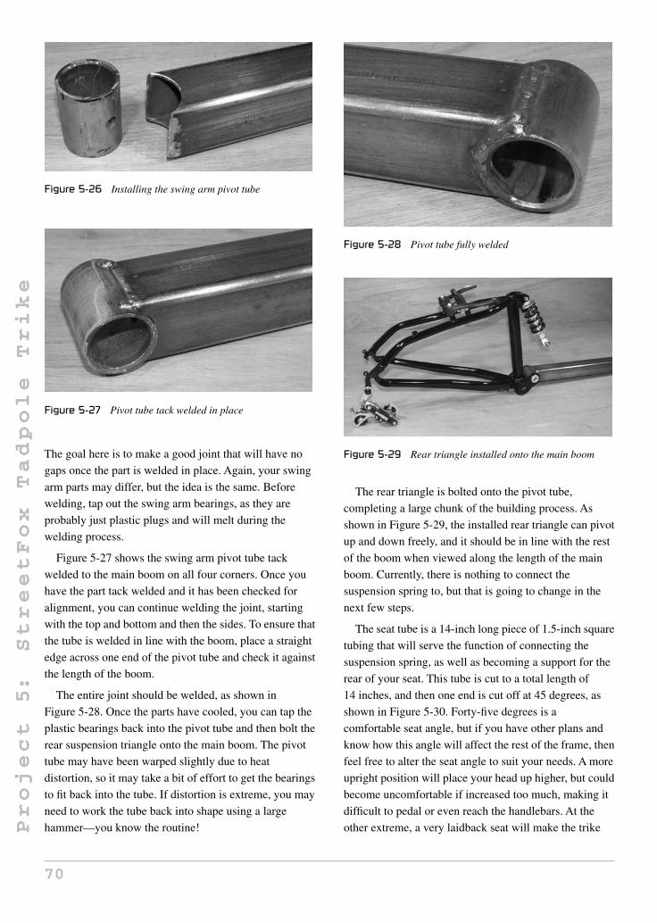
Project
5:
StreetFox
Tadpole
Trike
Figure 5-26 Installing the swing arm pivot tube
Figure 5-27 Pivot tube tack welded in place
The goal here is to make a good joint that will have no
gaps once the part is welded in place. Again, your swing
arm parts may differ, but the idea is the same. Before
welding, tap out the swing arm bearings, as they are
probably just plastic plugs and will melt during the
welding process.
Figure 5-27 shows the swing arm pivot tube tack
welded to the main boom on all four corners. Once you
have the part tack welded and it has been checked for
alignment, you can continue welding the joint, starting
with the top and bottom and then the sides. To ensure that
the tube is welded in line with the boom, place a straight
edge across one end of the pivot tube and check it against
the length of the boom.
The entire joint should be welded, as shown in
Figure 5-28. Once the parts have cooled, you can tap the
plastic bearings back into the pivot tube and then bolt the
rear suspension triangle onto the main boom. The pivot
tube may have been warped slightly due to heat
distortion, so it may take a bit of effort to get the bearings
to fit back into the tube. If distortion is extreme, you may
need to work the tube back into shape using a large
hammer—you know the routine!
Figure 5-28 Pivot tube fully welded
Figure 5-29 Rear triangle installed onto the main boom
The rear triangle is bolted onto the pivot tube,
completing a large chunk of the building process. As
shown in Figure 5-29, the installed rear triangle can pivot
up and down freely, and it should be in line with the rest
of the boom when viewed along the length of the main
boom. Currently, there is nothing to connect the
suspension spring to, but that is going to change in the
next few steps.
The seat tube is a 14-inch long piece of 1.5-inch square
tubing that will serve the function of connecting the
suspension spring, as well as becoming a support for the
rear of your seat. This tube is cut to a total length of
14 inches, and then one end is cut off at 45 degrees, as
shown in Figure 5-30. Forty-five degrees is a
comfortable seat angle, but if you have other plans and
know how this angle will affect the rest of the frame, then
feel free to alter the seat angle to suit your needs. A more
upright position will place your head up higher, but could
become uncomfortable if increased too much, making it
difficult to pedal or even reach the handlebars. At the
other extreme, a very laidback seat will make the trike
70

Project
5:
StreetFox
Tadpole
Trike
Figure 5-30 The seat tube has been cut
feel more like a low racer, making it difficult to
see properly in traffic or even over your own feet.
The top of the seat tube is cut off at 90 degrees and
needs to be capped off to keep out moisture and anything
else that may want to crawl inside. It is a rule of mine to
never leave an open-ended tube as this looks totally
unprofessional, allows moisture into the frame, and could
be a hazard due to the sharp edges of the tube. A simple
cap can be made by cutting out a 1.5-inch square section
of some scrap tubing, as shown in Figure 5-31. The cap
is simply welded along the seams, using only enough
heat to fill the joint with weld metal.
After welding the cap to the open end of the tube, use a
flap disc or sanding disc to clean up the joint, so the tube
will look like it never had an open end. Figure 5-32
shows the capped seat tube after a few minutes of joint
cleanup. These little details add up to take your final
product out of the home built zone into the professional
looking zone. It feels much better to be asked “how much
did that cool trike cost?” rather than “how long did it take
to build that?”
The seat tube is placed on the main boom in a position
that will allow the suspension to travel properly when the
main boom is placed at the required height from the
Figure 5-31 Never leave an open-ended tube
Figure 5-32 Capped tubing looks so much better
ground. I could just tell you to measure 9.5 inches from
the rear end of the main boom and mark a line, but
depending on the overall shape of your rear triangle and
the length of your suspension spring, the measurement
that I used may not work properly for you. Of course,
like all of my plans, I like to derive parts-dependent
measurements by using the “set it up and look” method,
which ensures that your final product works out,
regardless of small differences in your donor parts. There
are two conditions that need to be satisfied here, and to
ensure that you get the correct placement of the seat tube,
you will need to install the proper rear wheel with a fully
inflated tire, and have the suspension spring you plan to
use installed on the rear triangle.
The first requirement is the clearance from the
underside of the rear boom to the ground, which should
be 9 inches. For this, I simply found a bucket that was
9 inches tall and placed it under the main boom, as
shown in Figure 5-33. With the boom supported and rear
triangle populated with the wheel and suspension spring,
it is easy to see where the suspension spring needs to
connect to allow at least 2 inches of spring travel
(requirement number two). Try to choose a seat tube
position that allows the rear wheel to be lifted off the
Figure 5-33 Installing the seat tube onto the main boom
71

Project
5:
StreetFox
Tadpole
Trike
Figure 5-34 Looking for the optimal seat tube placement
ground two inches, but keeps the seat tube as far back as
possible to keep the wheel base short. The next few steps
will make this clearer.
If you place the seat tube way ahead of the rear
triangle, and try to connect the suspension spring to the
very top of the seat tube, you will have added an extra 6
to 8 inches of unnecessary length to the frame. Sure, this
would indeed work, and might be a good way to earn
some battery or luggage space, but unless that is your
goal, the seat tube should be placed as far back as
possible, putting the suspension spring mount lower on
the seat tube. In Figure 5-34, I have the seat tube taped to
the main boom as I try to find the optimal mounting
position, which was about 9.5 inches from the center of
the pivot tube to the rear edge of the seat tube. If I lifted
the rear wheel off the ground two inches, the top of the
triangle had about half an inch of clearance before it
would strike the top of the seat tube, so this was just fine
for my suspension spring, which had only 1.75 inches of
total travel. When you find the magic place, just park the
main boom so you can weld the seat tube in place.
Figure 5-35 shows the seat tube tack welded to the
optimal place on the main boom. A small tack weld is
first placed in the center of the joint, so you can ensure
that the seat tube is in line with the rest of the main boom.
View the two parts from all angles, and manipulate the
seat tube if an alignment adjustment seems necessary.
When welding square tubing, always start with the two
joints that will add the least amount of heat distortion
into your work and then complete the other two joints.
Here, the alignment is more critical from side to side, as
it is on the top of the boom where the seat tube makes the
45-degree angle with the main boom, so the top joints on
Figure 5-35 Tack welded seat tube
the main boom were welded first, followed by the two
joints on each side of the boom. The step angle on the
opposite side of the 45-degree angle is a little tricky, so
take your time and get it right. A little more amperage
into that joint might keep your arc welder from sticking,
if you are just starting out your welding career. When the
seat tube is completely welded to the main boom, there
should be very little side-to-side deflection if viewed
from the top of the frame or from either end. The
suspension spring mount will be installed after the front
wheels have been attached, which is the next step.
The two front wheels are held to the main boom by two
tubes I call the “front arm tubes.” On some trikes, these
two tubes are a single length, which would be called a
“cross boom,” but to ensure that shorter riders can enjoy
the StreetFox without having their ankles rubbing on the
frame, I decided to go with two tubes placed on an angle
to give shorter riders a lot more foot room. The standard
track (measurement across tire centers) is 30 inches, but
Figure 5-36 Seat tube completely welded
72

Project
5:
StreetFox
Tadpole
Trike
Figure 5-37 Front arm tubes allow for more footroom
this is another easily modifiable aspect of this project. If
you are on the heavier side, you may be more
comfortable with a 32-inch track, or may have radical
plans to make the StreetFox into a low-racing speed
machine, so a 27-inch track might be your goal. For
everyday riding and good stability, a track between 30
and 32 inches seems optimal, so I decided on a 30-inch
track. Again, measurements may change slightly
depending on the width of your front hubs, length of your
head tubes, and type of hub hardware, so we will make
all cuts a little longer than needed and work backwards,
using your parts as a guide. Start by cutting the two front
arm tubes to a length of 16 inches, as per Figure 5-38.
As shown in Figure 5-38, the two front arm tubes are
16 inches in length, with a 22.5-degree angle cut off one
end of each tube. You will note that 22.5 degrees is half
of 45 degrees, so if you fold a piece of paper diagonally
twice, you will have a handy guide to check the
22.5-degree angle.
The two front arm tubes are welded together at the
angle cut ends, so that they form a total angle of
135 degrees when welded together. An angle checker
verifies that I am very close to the desired 135 degrees
(Figure 5-39). Welding is done on the front and rear of
the joint and then only on the top of the joint, leaving the
bottom of the joint untouched so it can sit against the
main boom tube perfectly flat. If you were to weld all the
Figure 5-38 Front arm tubes
Figure 5-39 Joining the two front arm tubes
Figure 5-40 The side that will mate with the main boom
way around the two arm tubes, alignment of the main
boom tube would be difficult, since the weld would
create a high spot. As you will soon see, the side of the
joint that sits on the main boom tube does not need
welding, as it will be secured by the welding between the
rest of the front arm and main boom joints.
Figure 5-40 shows the side of the newly joined front
arm pair that was left unwelded so it can sit flat against
the main boom tube. If your welding has created a high
spot on this side of the joint, grind off any of the excess
welding bead until you can place a flat object directly
over the joint so it lays perfectly flat.
The top side of the front arm tubes is fully welded, as
shown in Figure 5-41. Since the front arms are now
joined to create one single piece, I will now refer to them
simply as the “front arm tube.”
Whenever a non-critical weld is clearly visible, I try to
grind the weld metal flush with the original tubing for
aesthetic purposes. You might think that the weld holding
the two arm tubes together is one of the most
strength-critical welds on the entire frame, but as you
will soon see, the joint between the main boom and the
unwelded side of the front arm boom is what really holds
the front arm boom to the main boom, so you can easily
afford to clean up the top weld. Figure 5-42 shows the
results of some careful grinding and touchups using a
73

Project
5:
StreetFox
Tadpole
Trike
Figure 5-41 Front arm tubes joined
Figure 5-42 Front arm tube joint cleaned up
flap disc. While cleaning up welds, be careful never to
dig into the weld material, creating a valley in the joint.
A little hill over the joint is much better than a little
valley, which could seriously compromise the strength of
the joint.
Now that you have the two front arm booms joined
together to form the front boom, you must trim them
down to achieve the desired track, since the initial
measurement given was longer than you need. Track is
measured across the fully inflated tire centers, so you will
need to have your front wheels installed on the head
tubes with fully inflated tires and all the head tube
hardware installed. As shown in Figure 5-43, you need to
know the distance from the center of the head tube to the
center of the tire (or rim), in order to determine how
much material needs to be trimmed off the front arm
boom in order to end up with the desired track. Again,
30 inches is a good track width to shoot for unless you
have other requirements. It may be difficult to measure
the distance from the center of the head tube to the rim
center with military accuracy, so just try to get a decent
estimate within a quarter inch or so. My measurement
was 2 inches, but yours may differ slightly.
Figure 5-43 Measuring the head tube to tire center distance
Figure 5-44 Calculating track based on the arm boom
Once you have determined how far it is from a head
tube center to the rim center, you can use that
measurement to figure out how much length needs to be
cut from the arm boom to get the desired track width. We
took the measurement from the center of the head tube,
since this is approximately where it will end up once you
cut the fish mouth out of the arm boom to weld it in
place. Now, run a measuring tape across the arm boom
assembly from center to center, as shown in Figure 5-44,
so you know what the track would be right now if the
arm boom was left uncut. The distance across my arm
boom assembly from center to center is currently
28.5 inches, so if I add the extra width given by the two
head tubes (2 × 2 = 4 inches), I would end up with a
32.5-inch track. Obviously, I will need to chop off
1.25 inches from each arm on the arm boom assembly to
end up with the desired 30-inch track. Therefore, the
distance across my arm boom assembly needs to measure
exactly 26 inches after trimming.
Figure 5-45 shows a closeup of how the arm boom is
to be measured across its width. A small mark indicating
the center of the tube is drawn, and this is where the
measurement is taken at each end of the arm boom
assembly.
74

Project
5:
StreetFox
Tadpole
Trike
Figure 5-45 Measuring the overall arm boom width
Figure 5-46 Trimming the front arm boom assembly
After a little calculating magic, I determined that the
overall width from point-to-point on my front boom
assembly needed to be reduced by 2.5 inches, so
I marked a 1.25-inch cut line at the end of each arm, as
shown in Figure 5-46. The resulting center-to-center
distance of my arm boom will soon be 26 inches, creating
a trike with a 30-inch track by adding the distance from
each head tube to the wheel center (4 inches in total).
The head tubes are welded to the ends of the front arm
boom at such an angle that the tires end up at 90 degrees
to the ground. Since we are using center point steering,
the head tube angle is not the same as the axle or the
wheel, so this needs to be taken into account when
cutting the fish-mouth joint on each end of the front arm
boom. For now, simply trace a line using a head tube (or
something of equal diameter) on the top of the front arm
boom assembly, as shown in Figure 5-47. The top of the
arm boom is the side with the weld, opposite to the
non-welded side.
The front arm boom will mate with the top of the main
boom at a distance of 12 inches, as measured from the
point of contact to the 45-degree corner formed between
the seat boom and main boom. This distance allows
Figure 5-47 Cutting the fish mouth for the head tubes
Figure 5-48 Joining the arm boom to the main boom
plenty of room to mount your seat base, and places the
handlebars in an easy-to-reach, comfortable position.
Figure 5-48 shows the first tack weld made at a distance
of 12 inches from the seat corner as described. A single
tack weld is made so that the angle can be checked and
easily adjusted if needed, in order to get the two arms at
the same angle in relationship to the main boom tube. An
adjustable square or angle finder is used to compare each
side, making slight adjustments until they are both equal.
At that point, you can place another tack weld on the
front of the joint to lock down the angle.
Figure 5-49 shows the front arm boom tack welded in
two and placed along the top to lock it in position after
the angles on each side have been checked to be equal.
Notice that there is plenty of room (12 inches) for your
seat base, so you can use very thick seat padding if you
like. A mesh seat with a frame could also be installed as
there is plenty of room. Also notice that the arm boom is
welded on the top side of the main boom, which will help
keep your chain line simple and clean.
75

Project
5:
StreetFox
Tadpole
Trike
Figure 5-49 Front arm boom in position
Figure 5-50 Welding the front arm boom to the main boom
With the angles between each arm and the main boom
equal, complete the joint by welding the two top sides
first. You will want to use a clamp or vice to hold the
boom securely to the frame to avoid any side-to-side
distortion caused by welding heat. Figure 5-50 shows the
completed welds on the front and back side of the arm
boom and main boom.
Once the top of the arm boom and main boom joint is
welded, you can finish up on the underside of the joint, as
shown in Figure 5-51. Use the smallest bead of weld you
can in order to keep heat distortion to a minimum, and
make sure you weld both sides using equal amperage and
travel speed so any deflection is equal on both sides.
It’s time to play “good news, bad news.” The bad news
is that the next step is by far the most complicated part of
the entire build, and will most likely require more than
one try to get right. The good news is that, after this, you
are home free, as the rest of the build will feel like
smooth sailing. Head tube angle is your battle now, and it
is by far the most difficult part of a tadpole trike build,
which is why many first-time builders go for the
delta-style trike instead. You have to get the head tube
Figure 5-51 Welding the underside of the arm boom
angles correct in two ways: first, the center point angle,
and then the caster angle. Oh, and you have to do this
twice, making sure everything is the same on both sides!
OK, if you are still reading, then that means you have
decided to build a tadpole trike, no matter what, so let’s
get going and begin the fun! I recommend that you use
another spare head tube or some equal diameter tube as a
guide, so you can easily check your progress by placing
the tube in the joint, as shown in Figure 5-52.
As shown in Figure 5-53, you need to get the head
tubes on such an angle that the wheels are standing at a
90-degree angle to the ground, and the head tubes are
angled slightly forward, creating the desired 75-degree
caster angle. The 75-degree angle allows the wheels to
self center, creating a more stable ride at high speed with
a good degree of response. If you relax this angle too
much, your wheels will tend to flop from side to side, and
you will increase your turning circle by reducing the
amount of steer. If you make the head tube angle too
steep, then your steering will be instantly responsive and
Figure 5-52 Figuring out the head tube angles
76

Project
5:
StreetFox
Tadpole
Trike
Figure 5-53 Head tube angles of concern
somewhat “twitchy,” especially at higher speeds, where
you will tend to wobble back and forth as you pedal hard.
Seventy-five degrees seems to be a good angle for a trike
of this wheelbase, but feel free to alter this angle if you
feel that you know what you are doing and how it will
change the handling characteristics.
The alignment of each head tube will be determined by
the shape of the fish mouth cut at each end of the front
boom arm, which is why the top cutout was made earlier
as a starting point to work from. You should take a small
amount of metal out a bit at a time and check your angles
often, in order to avoid taking out too much material all
at once. The odd looking fish-mouth cut shown in
Figure 5-54 is what I ended up with after spending an
hour or two with a small grinding disc and a round hand
file. There is no magic formula or easy method I know of
to get these angles in a hurry, so be prepared to spend
some quality time with old-fashioned hand tools.
What about a frame jig? Don’t professional frame
builders use those? They sure do, but how do you make
sure the jig has the correct angles? Or how do you ensure
the jig is going to be rigid enough to withstand the forces
Figure 5-54 Adding the proper fish mouth to each end of the
arm boom
of welding? Wood is certainly out. In the end, it would be
twice as much work to create a proper jig, and a
professional custom jig for this project would cost
10 times the price of a manufactured trike imported from
across the globe. Dude, you will need to have to open a
can of patience on this one!
Using my favorite bucket trick, I raised the front boom
up to the correct height to check my work each time
I took a little metal out of either of the fish-mouth cuts.
The front arm boom should meet each head tube as low
as possible, leaving about half an inch of head tube
material sticking out past the underside of the boom arm,
so you can weld the joint without melting the edge of the
head tube. This height is not critical, since it is really
determined by the height of the head tubes, but on my
trike, this height was approximately 11 inches, slightly
ahead of the boom joint where my bucket is placed in
Figure 5-55.
The process of grinding a little, then checking angles
takes a while, but if this was easy, then everyone would
have a cool custom trike, and the results of your hard
labor would then be worth a lot less! If you want to keep
the head tubes locked on the fork stem, you can add some
tape around the bearing cups, or simply remove the top
bearings, which will keep the head tube from rolling all
over the place when you are using the wheels as a guide,
as I am in Figure 5-56. No welding is done until both
wheels pass visual alignment inspection from every
possible angle.
After your grinding, filing, and inspecting ordeal is
over, it is time to weld the head tubes to the arm booms
so you can get on to the easy stuff, like riding your trike.
Again, I cannot offer any magical solutions that will
ensure an instantly aligned head tube pair with minimal
effort, so be prepared to fiddle, break tack welds, and try
your patience. I prefer to place the frame up high enough
Figure 5-55 Checking my head tube angles
77

Project
5:
StreetFox
Tadpole
Trike
Figure 5-56 More visual angle inspection
Figure 5-57 Welding the head tube in place
so I can stand back and compare the wheels to the
ground, and the wheels to each other. Figure 5-57 shows
the main boom held securely and parallel to the ground
using a workbench vice. At this point, I also placed one
small tack weld on each head tube, hoping that my
fish-mouth cuts were close enough that I could force
each head tube into alignment and continue welding.
I was lucky with the left side, but the right side was
visually out of alignment enough that I decided to do a
little more filing to correct the error. This is one stage in
the build where correcting your errors will make a huge
difference to the look and feel of the finished product.
I normally do not weld a frame with my good wheels
or bearings installed, but this is one time where it is
impossible to do otherwise, as you really need those
wheels up on the bench for close visual inspection.
An old towel or cloth placed over the tire and rim will
keep welding spatter off the wheel, and always place
Figure 5-58 Two tack welds secure the head tube
your ground clamp on the frame, not the head tube
hardware, or current will surge through the bearings and
destroy them or the cups. With a single tack weld on the
head tube, you should be able to manipulate the head
tube enough to get the wheel aligned the way it needs to
be, with a focus on the wheel being at 90 degrees to the
ground. When the wheel is where it should be, another
tack weld on the other side of the joint should hold that
head tube securely enough to later remove the fork
hardware once both sides are looking good. Remember,
this alignment counts, so break a tack weld and file away
if you need to.
With both head tubes securely tack welded in place,
perform one last vigorous alignment quality check
because the next step is the point of no return. I placed
the frame and wheels back on the ground and then put
both wheels in the straight ahead position, so I could
check their 90-degree alignment directly from the front,
as shown in Figure 5-59. If both wheels seem to be
standing at a perfect 90 degrees to the ground, then there
is a good chance that both your head tube caster angles
are also close to the desired result and equal as well.
Look through the spokes at both head tubes to see if they
are both at the same angle, and a very slight difference is
not nearly as bad as a wheel not being at 90 degrees to
the ground. If one wheel seems to be “gimpy,” then get
busy and fix your work, as this will surely be seen by
others and make your work look poor.
Welding the head tubes in place is done like any other
welding, starting along the top of the joint, then the
78

Project
5:
StreetFox
Tadpole
Trike
Figure 5-59 One last quality check before welding
Figure 5-60 The battle is now over
bottom, and finally the sides. Weld both parts using the
same sequence, so that any distortion is copied to both
parts equally, and ensure that there are no holes or gaps
in the weld. It’s a good idea to tap in an old head tube cup
on the lower side of the head tube when you are welding,
as this will help keep the head tube from becoming oval
from heat distortion. Figure 5-60 shows one of the head
tubes fully welded around the joint.
Figure 5-61 shows the nearly completed StreetFox
frame after an epic adventure with multiple and duplicate
angle cutting and welding. If you enjoy bicycle building
as a hobby, then every minute of the building process so
far was pure fun, but you can sure learn to appreciate the
high price tag on a tadpole trike when you consider how
much effort it takes to get here. If this were a two-wheel
recumbent bicycle, I would have been on my third
Figure 5-61 The hard part is now completed
hundred mile ride by now, but the final product will be
worth it nonetheless.
Once your suspension spring is mounted to the frame,
you will be able to place all three wheels on the trike and
roll it around your garage or shop—a great milestone in
any bike build. The suspension spring is held to the rear
of the seat tube using a pair of 1/8-inch bits of flat bar, or
you could simply slice them out of your donor mountain
bike frame like I did. As shown in Figure 5-62, the
suspension mounting tabs can be cut from the donor
frame, bypassing the need to drill the appropriate holes
for the mounting bolt.
The suspension mounting tabs are shown in
Figure 5-63, salvaged from what was left of the original
mountain bicycle frame. If you decide to use flat bar to
make the tabs, then just make sure you make them both
the same size and drill the appropriate hole in each for
the suspension spring bolt.
Since you have already figured out where your
suspension spring needs to be mounted, it’s just a matter
of installing the tabs on the suspension spring, then using
it as a guide to make the first few tack welds. The spring
can then be removed and the tabs completely welded to
Figure 5-62 Salvaging the suspension mounting tabs
79

Project
5:
StreetFox
Tadpole
Trike
Figure 5-63 Suspension mounting tabs ready
Figure 5-64 Suspension spring mounted
the rear of the seat tube, as shown in Figure 5-64. I would
recommend that you install the front wheels and fork
hardware, and then get out that 9-inch tall bucket to prop
up the rear of the frame, just so you can ensure that your
ground clearance is exactly what it should be. When your
suspension spring is secured to the seat tube, you should
be able to jump up and down on the frame and have the
suspension take it all in stride. No part of the suspension
spring body should rub on the frame as the spring
compresses and expands.
Braking on a tadpole trike is another puzzle that is a
little more complex than a delta trike. Personally, I would
be just fine with trusting one good rear brake, and often I
will leave it at that and allow the builder to decide if he or
she wants to install standard caliper brakes on the front
of a bike. Of course, standard front brakes are simply not
an option on this trike, since there is no place to mount
them, so this will be addressed. Some tadpole trikes have
hard-to-find custom drum brake hubs or disc brake hubs
with custom axles, but the goal here is to avoid all
Figure 5-65 Cutting the brake support arms
expensive or non-standard parts, so I will avoid those
two options. Another puzzle is what to do with three
brakes and two levers, but there are always answers. To
get a brake on each front wheel, you will need to make a
brake support arm that allows you to place a standard
bicycle brake in the appropriate place around the wheel.
To do this, a pair of L-shaped brake support arms will be
made from some 3/4-inch square tubing with a 1/16-inch
wall thickness (same thickness as the boom tubing).
These tubes are shown cut in Figure 5-65.
The brake support arms need to wrap around the inside
of each front wheel to allow the installation of a standard
caliper-type bicycle brake. Because of the tight half-inch
clearance between the brake support arms and the tire,
you should read ahead and consider making the length of
the tubes slightly longer so you can work backwards,
especially if your front tires are quite wide or have
aggressive tread. The measurements given in Figure 5-66
are based on a 2-inch wide, 20-inch tire with minimal
tread, which is a common choice of tire for this project.
Much wider and taller tires are certainly available.
The two brake support arms are shown in Figure 5-67
after tack welding them together for a test fitting. The
brake arms will connect to the fork crown (shown ahead
in Photo 64), and should come around the tire so that
there is half an inch between the widest part of the tire
sidewall, as well as between the top of the tire and the
Figure 5-66 Brake support arms
80
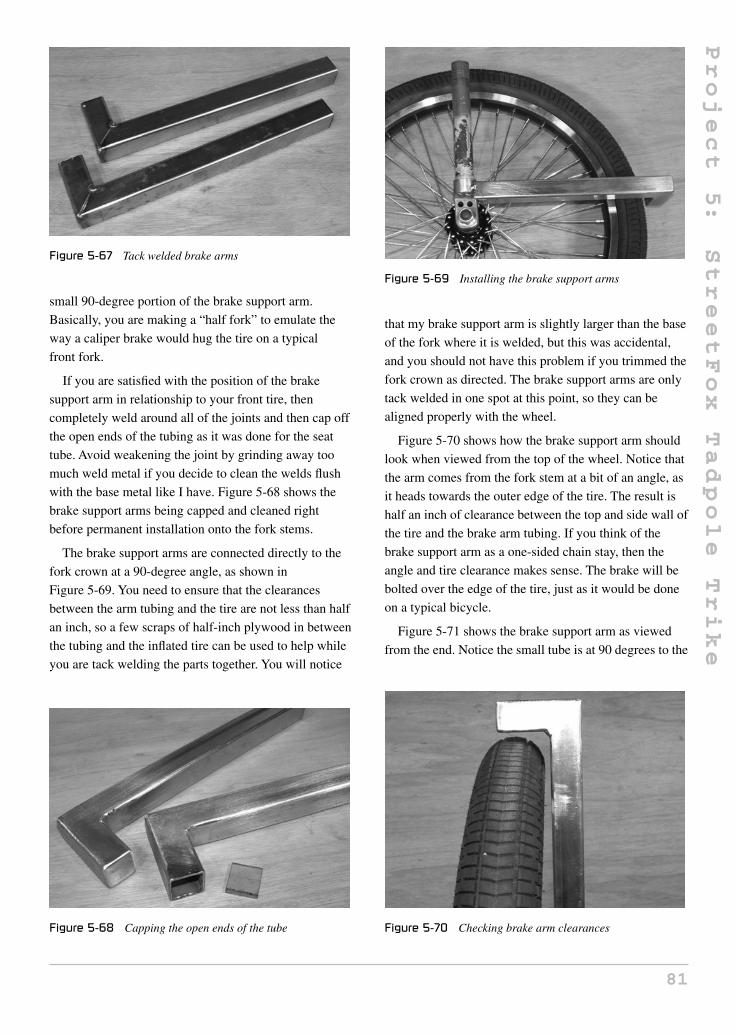
Project
5:
StreetFox
Tadpole
Trike
Figure 5-67 Tack welded brake arms
small 90-degree portion of the brake support arm.
Basically, you are making a “half fork” to emulate the
way a caliper brake would hug the tire on a typical
front fork.
If you are satisfied with the position of the brake
support arm in relationship to your front tire, then
completely weld around all of the joints and then cap off
the open ends of the tubing as it was done for the seat
tube. Avoid weakening the joint by grinding away too
much weld metal if you decide to clean the welds flush
with the base metal like I have. Figure 5-68 shows the
brake support arms being capped and cleaned right
before permanent installation onto the fork stems.
The brake support arms are connected directly to the
fork crown at a 90-degree angle, as shown in
Figure 5-69. You need to ensure that the clearances
between the arm tubing and the tire are not less than half
an inch, so a few scraps of half-inch plywood in between
the tubing and the inflated tire can be used to help while
you are tack welding the parts together. You will notice
Figure 5-68 Capping the open ends of the tube
Figure 5-69 Installing the brake support arms
that my brake support arm is slightly larger than the base
of the fork where it is welded, but this was accidental,
and you should not have this problem if you trimmed the
fork crown as directed. The brake support arms are only
tack welded in one spot at this point, so they can be
aligned properly with the wheel.
Figure 5-70 shows how the brake support arm should
look when viewed from the top of the wheel. Notice that
the arm comes from the fork stem at a bit of an angle, as
it heads towards the outer edge of the tire. The result is
half an inch of clearance between the top and side wall of
the tire and the brake arm tubing. If you think of the
brake support arm as a one-sided chain stay, then the
angle and tire clearance makes sense. The brake will be
bolted over the edge of the tire, just as it would be done
on a typical bicycle.
Figure 5-71 shows the brake support arm as viewed
from the end. Notice the small tube is at 90 degrees to the
Figure 5-70 Checking brake arm clearances
81

Project
5:
StreetFox
Tadpole
Trike
Figure 5-71 Brake arm view from the end
Figure 5-72 Welding the brake support arms
tire rather than the fork stem to which it connects. This is
necessary as the brake also needs to be mounted at
90 degrees to the wheel so the brake pads hit the edge of
the rim squarely.
The brake support arms can be completely welded to
the fork stem crown, as shown in Figure 5-72, once you
have checked the alignment with the tire. Welding should
be solid and gap free, as the brake arms will be put under
considerable stress during a fast stop from high speeds.
As mentioned earlier, I cut the fork stem a bit too short,
so I had to weld part of the brake arm tubing to the axle
mounting hardware as well, but this worked out fine.
The same process must be done to both brake arm
support tubes, making sure alignment with the wheel and
rim is correct for proper braking contact. Figure 5-73
shows the two completed parts ready for installation.
Figure 5-73 Brake arms fully installed
Figure 5-74 Steering almost completed
At this point, you can roll your trike forward and the
two front wheels will fall into line, and automatically
track together due to the caster angle of the head tubes
(Figure 5-74). Of course, you can’t expect this to be safe
on the road, and if you try to move the trike in reverse, the
two wheels will point together and instantly lock up the
vehicle. Like any vehicle with dual front steered wheels,
the two wheels must be made to turn together, taking into
account that the wheel on the inside of a corner must
actually turn sharper than the wheel on the outside. This
might sound like a complex problem best solved by some
computer controlled hardware system, but is actually a
very simple problem to solve. The name for this type of
steering is “Ackermann Steering,” and you can learn a lot
about how it works by hitting your favorite search engine
for more information. The good news is that I have
figured out all the proper steering geometry by hours of
trial and error, so you will not have to, although knowing
how it actually works is always a good thing.
The two front wheels will turn together because they
are joined by a pair of steering control arms, a pair of
82

Project
5:
StreetFox
Tadpole
Trike
aspherical rod ends (ball joints), and a control rod. The
position of the control arms in relationship to the pivot
point of the fork stem actually determines how much one
wheel increases its angle on the inside of a corner, so we
can say that Ackermann Steering is just a factor of
control arm placement. If you have too much Ackermann
effect, then the inside wheel will start to scrub or
completely lock up as it flops all the way against the
frame. If you have too little Ackermann, or none at all,
then one of the wheels will have to scrub around every
corner, causing you to slow down and wear out your
front tires in a hurry. Figure 5-75 shows the two control
arms, which are nothing more than 2-inch long pieces of
1-inch wide flat bar with a thickness of 1/8 to 3/16 inches.
The holes are drilled approximately half an inch from the
ends, and are the size needed to connect the ball joints
that you decide to use.
Mark a point on the underside of the brake support arm
5 inches from the welded joint, as shown in Figure 5-76.
This location is where you will install the control arms
for proper Ackermann steering compensation. The X
marked on the far side of this line indicates that the
control arm is on that side of the line, not on the center of
the line. To determine this control arm location, I spent
Figure 5-75 Steering control arms and bolts
Figure 5-76 Control arm position
Figure 5-77 Control arms installed
the day trying random places along the brake support
tube, using many different length control arms until I
could make every possible turning circle with little or no
tire scrub. This took at least 20 attempts. There are
formulas and charts available on the Internet that can
help determine this for you, but I found that “trial and
error” is the best method. Old-fashioned hard work is
always the way to win any battle!
Figure 5-77 shows the two control arms welded to the
brake support tubes, so the distance between the edge of
the control arm and the fork stem is 5 inches. The 3/8-inch
holes drilled in the control arms match the ball joints
I found at the local hardware store.
Ball joints are actually called “spherical rod ends,” so
remember that if you are asking for them at a bearing
store, as they like to use the proper terminology. Most of
us just call them “ball joints,” so I will continue to do so
from now on. The two ball joints and the control arm are
shown in Figure 5-78. My ball joints have a bolt on the
body, and require a bolt to hold them down, while some
may be the opposite, including the bolt on the ball part
instead. It really is not important which type you choose,
as long as the bolt or bolt hole is no smaller than 3/8, and
the ball or bearing is not made of plastic. The control rod
Figure 5-78 Ball joints and connecting rod
83

Project
5:
StreetFox
Tadpole
Trike
Figure 5-79 The bolt fits inside the control rod
is just a half-inch hollow tube from the hardware store
with a 1/16-inch wall thickness. The 3/8 bolt just fits into
the tube, so this allows a nut to be welded at each end of
the tube to make the steering alignment adjustable.
Figure 5-79 shows how the 3/8-inch bolt fits right into
the hollow control rod, using a nut to allow the ball joint
to be adjusted about half an inch up or down. This nut
will be welded directly to the end of the control rod, and
then another nut will be used to lock down the ball joint
once the two front wheels have been perfectly aligned.
The length of the control rod is determined by installing
all the front wheel hardware and the rear wheel, then
walking the trike forward until both front wheels have
tracked together for at least a 4-foot distance. At this
point, try not to disturb the front wheels as you measure
the exact distance from the center of each hole on the
control arms that you just welded in place. You can then
subtract whatever length is needed from this
measurement, so that the ball joint holes will be the same
distance apart as the holes in the control arms. The ball
joints should be set up so that they can be screwed in or
out the same amount, allowing optimal tire alignment
fine tuning in each direction.
Figure 5-80 shows what the completed control rod
should look like once the nuts have been welded at each
end of the tube, and the ball joints screwed in and locked
down. At this point, the center-to-center distance
between ball joint holes is exactly the same as the
center-to-center distance between the control arm holes
after rolling the trike forward. I did not even have to do
any fine tuning of the steering alignment after this point,
as the steering was tracking perfectly and friction-free,
after assembling the trike for the very first time.
Figure 5-80 Completing the steering control rod
Figure 5-81 Installing the control rod and ball joints
Figure 5-81 shows the control rod installed by putting
a bolt through all of the joints and the two control arms.
I recommend that you use good quality bolts with plastic
lock nuts for all steering hardware, so that the nuts don’t
work their way loose over time due to vibration. If you
lose the control rod at high speed, one wheel may flop to
the side and cause the vehicle to roll or steer wildly out
of control. Don’t take chances with low quality parts on
steering or braking components.
The ball joints are placed on top of the control arm, as
shown in Figure 5-82, so they are easy to inspect every
once in a while. You could certainly place them on the
other side of the control arm, but then they are always
hidden from your view.
Once the steering system is ready for testing
(Figure 5-83), the trike should roll in a straight line
without any resistance, and steer around most sharp
corners without any tire scrub. Obviously, steering too
far in one direction will cause the inner wheel to travel
past the steering center and literally flop all the way over,
but in normal steering conditions, this will never happen.
If you move the wheels from side to side, you can really
see how the Ackermann steering affects the inside wheel,
84

Project
5:
StreetFox
Tadpole
Trike
Figure 5-82 Ball joint and control arm closeup
Figure 5-83 Testing the steering system
causing it to steer at a tighter angle the farther you move
the outer wheel. If your trike seems to roll with any
friction or obvious tire scrubbing, then you will have to
unbolt one of the ball joints and adjust it properly.
Remember, rolling the trike forward and allowing the
two front wheels to self center is a good way to find the
perfect alignment point.
It would be very difficult to guess the exact placement
of the bottom bracket for your inseam without making a
small error. A fixed bottom bracket also means that you
could never alter the seat, or adjust the StreetFox for
anyone but yourself, so an adjustable bottom bracket is
the only option. If you cut the bottom bracket from an
old bicycle frame, and leave a 12-inch or longer section
of the seat tube connected, you can create a very
functional, adjustable bottom bracket with nothing more
than a pair of steel plates. The bottom bracket and
included seat tube will be mounted to the main boom
Figure 5-84 Creating an adjustable bottom bracket
with a clamp arrangement that allows the assembly to be
placed practically anywhere on the boom, allowing riders
of varying heights to ride the bike. The two plates shown
in Figure 5-84, along with the bottom bracket and seat
tube stub, will form the sides of the clamp that will hold
the bottom bracket against the side walls of the main
boom, as they are forced together by two bolts.
The bottom bracket and front derailleur tube move
together along the main boom, so you do not need to
worry about the position of the derailleur over the chain
ring. The chain is cut to the perfect length once the
bottom bracket has been adjusted for the main rider, but
will still allow a few inches of adjustment in either
direction without a chain alteration due to the
spring-loaded rear derailleur. Of course, the
difference between a 6-foot, 5-inch person versus a
4-foot tall person will likely require some chain
adjustment, but this can be done in less than a minute
with an inexpensive chain link tool. Cut two 3/16-inch
thick pieces of plate or sheet to make the shapes, as
shown in Figure 5-85. The round area is cut to conform
to whatever size bottom bracket you decided to go with,
Figure 5-85 Bottom bracket mounting plates
85

Project
5:
StreetFox
Tadpole
Trike
and the two bolt holes will be drilled for 1/4-inch bolts.
The bolt holes are drilled at the edge of the plates, so that
there is 1/8 inch of material between the hole and edge of
the plate. These two plates will form a “vice” that will
clamp the bottom bracket to whatever position on the
main boom you want.
Trace around the bottom bracket shell to draw a line
on the plates, as shown earlier in Figure 5-84. The
marker line should meet the corners of the plate to ensure
that you don’t cut out too much off the plate when
grinding out the rounded area. If you take too much
metal away from the plate, there will not be enough room
between the bottom bracket and the clamping bolts for
the main boom. When grinding out the traced circular
area for the bottom bracket, as shown in Figure 5-86,
place both plates in the vice so they can be done at the
same time; this will ensure that both plates are exactly
the same size. Try to make the gap as small as possible
around the bottom bracket shell, so that there is less
distortion as the plates are welded. If the bottom bracket
becomes overly distorted, it will be a serious challenge
trying to screw the hardware back into the bottom
brackets without stripping the threads.
In order to get the two plates aligned with each other
and at the correct spacing, a bit of frame tubing can be
clamped between the two plates, as shown in
Figure 5-87. This will allow you to set the bottom
bracket into the correct position for tack welding, as well
as to ensure that both plates are aligned with each other
so the bolt passes easily through both holes. I also placed
a sheet of paper (folded in half) between each plate and
the side wall of the tubing, in order to allow a little
Figure 5-86 Shaping the bottom bracket plates
Figure 5-87 Setting up the plates for welding
Figure 5-88 The proper derailleur tube angle
clearance between the clamp plates so that the unit is not
so difficult to slide when making adjustments. Without
the small gap, it is easy to scratch the paint if you plan to
move the bottom bracket around a few times.
As shown in Figure 5-88, I used an adjustable square
set to the required 56 degrees, in order to set up the
bottom bracket and derailleur tube to place two small
tack welds at the top of the joint. It may be a bit tricky to
get the first tack weld in place while holding the bottom
bracket in position, but once this is done, the rest is easy.
With the piece of frame tubing as a guide, you will
automatically have the correct distance between the
plates. Now, you will need to ensure that there is
approximately equal distance between each plate and the
edges of the bottom bracket. In other words, the bottom
bracket will be in the center of the main boom as viewed
from above.
Figure 5-89 shows the first tack welds done at the top
edge of the plates in order to secure the parts together.
Ensure that the derailleur tube angle is close to 56 degrees
and that the bottom bracket is at 90 degrees to the square
86

Project
5:
StreetFox
Tadpole
Trike
Figure 5-89 Tack welding the plates to the bottom bracket
tubing. You can also move the clamps to hold the plates
in a position that will allow you to weld around the entire
joint, but do not begin welding without them as there
may be distortion. Also, welding is only done on the
outside of the joint, not between the plates. If the inside
of the joint is welded, the weld bead will not allow the
bottom bracket to sit directly on the frame tubing and
could cause alignment problems. Because of the way the
clamp system works, there would be no added benefit
from welding the inside of the joint anyway.
The two plates will form a vice-like grip on the frame
tubing when the 3/8-inch bolts are tightened. In order to
drill the holes into the plate, draw a line that represents
the bottom corner of the frame tubing, as shown in
Figure 5-90. Now you can punch and drill the holes using
the line as a guide that will allow you to ensure that the
holes stay below the line. If the holes are not below the
line, you will not be able to pass the bolt through both
plates because it will hit the frame tubing instead.
With the derailleur tubing cut to length, it is a good
idea to cap off the open end of the tubing so that it looks
Figure 5-90 Marking a line to drill the bolt holes
Figure 5-91 Capping the end of the derailleur tube
better and keeps any moisture out. As shown in
Figure 5-91, a washer is welded over the end of the tube
and then completely filled in around the joint and the
hole. To fill in the washer hole, several passes are made
around the edge until completely covered in weld metal.
After welding the washer in place and grinding the
area clean, you can’t even tell that the tube shown in
Figure 5-92 once had an open end. Going the extra mile
can make you final product look very professional,
possibly even better than some mass produced machines,
since they might have simply capped the hole with a
plastic plug to save time.
Figure 5-93 shows the sliding bottom bracket secured
to the frame. Notice that the bolts are fairly close to the
underside of the frame tubing, thanks to the guide lines
used to drill the holes. The derailleur tube is very close to
the 56 degree angle as well. Tighten the bolts enough so
that you can’t force the bottom bracket to move by
pulling on the derailleur tube, but not too tight, or you
may actually crush the frame tubing. Don’t bother
Figure 5-92 Completed adjustable bottom bracket
87

Project
5:
StreetFox
Tadpole
Trike
Figure 5-93 Testing the adjustable bottom bracket
greasing up the bottom bracket bearings just yet, as you
will want to do that after the priming and painting is
completed.
You are almost ready to cut the proper length of chain
and connect your transmission system. The obvious
problem right now is that the chain will rub on the
underside of the right front arm tube, so an idler pulley
needs to be installed in order to guide the chain under the
tubing. Almost all tadpole trikes have at least one drive
side idler pulley. This is unavoidable due to the low seat
height and position of the front chain ring. Fewer chain
idlers and less of a bend in the chain is always better,
since idlers and sharp chain bends cause extra friction in
your drive line, robbing you of your top speed.
The StreetFox has only a single idler and it only bends
the chain slightly, so the transmission is very efficient.
Figure 5-94 shows the V-belt idler pulley that is used to
guide the chain—it is a commonly available 3-inch
diameter 1/2 V-belt idler pulley with a 3/8 ball bearing
mounted in the center.
Figure 5-94 A V-belt idler will guide the chain around
the frame
You can find these pulleys at any lawn and garden
supply center and many hardware stores. A hard nylon
V-belt pulley will also work, but make sure that the
bearing in the center is a good ball bearing, not some
cheap brass bushing, as that will add massive friction.
The cut-up bolt, also shown in Figure 5-94, is a
lawn-mower wheel-mounting bolt, which just happens to
fit the 3/8 bearing hole in my idler pulley. Any decent
quality bolt will work for this, as the goal is to mount the
pulley about one inch off the side of the main boom.
Some trike builders have used skate blade or skate board
wheels with the center ground out to take the chain, but I
would avoid that system as it causes extra friction due to
the softness of the wheel material, and the diameter of
the pulley should not be less than 3 inches when installed
on the drive side of the chain. The skate wheels system
also allows the chain to jump out of the track easily,
forcing you to add some type of chain-stopping plate, so
it really is not worth the hassle just to avoid spending $5
on a good quality V-belt idler pulley.
The chain idler pulley is mounted to the right side of
the main boom just behind the right front arm tube, as
shown in Figure 5-95. Hold the pulley against the frame
so you can determine the best place to install the idler
pulley bolt. When you are done, the pulley should be as
close to the arm tube as possible without rubbing, and the
pulley should stand off from the frame about 1 inch,
which is why the lawn-mower wheel bolt worked
perfectly for this job. A bolt and a few nuts could also be
used if you can’t find a decent shoulder bolt like I did.
Figure 5-96 shows the chain idler pulley guiding the
drive side of the chain around the right front arm tube at
a very slight angle. At this point, you can install your
Figure 5-95 Installing the idler pulley bolt
88

Project
5:
StreetFox
Tadpole
Trike
Figure 5-96 Chain idler pulley in action
front cranks, rear derailleur, and fiddle around with your
chain tool until you get the chain cut to the correct
length. A chain link tool can be purchased from any
bicycle shop for about $20, and will save you countless
bangs on your thumbs if you try to break and connect a
chain using a punch and hammer. You will probably need
two full bicycle chains, and possibly a small part of a
third chain to make the trike chain, so try to ensure that
all chain segments are the same size and type. Bicycle
chains are not expensive, so it might be best to work with
new materials here.
Seating is a personal choice, and since the StreetFox
has such a simple frame, you can install just about any
type of seat you would like, from a simple board seat to a
high-tech adjustable mesh and frame style seat. I prefer
the simple board and pad seat over mesh seating, so I
will show you how to fashion a comfortable and simple
seat using some plywood, foam, and fabric. To use a
board-style seat, you will need to bolt it directly onto the
frame, but since drilling holes into the main boom is a
bad idea, a few seat mounting tabs like the ones shown in
Figure 5-97 need to be made. Four lengths of 2-inch
long, 1/16-inch thick flat bar have been cut, and will be
Figure 5-97 Seat mounting plates
Figure 5-98 Installing the seat mounting tabs
welded to the main boom to hold down the two plywood
seat boards.
The two-piece plywood seat has a base and a back,
which are bolted to the seat mounting tabs. The tabs are
welded to the main boom and seat tube, as shown in
Figure 5-98. The tabs are flush with the top of the square
tubing, and the welds are ground flush as well. You can
now mount any type of plywood seat, or even a fishing
boat seat to the frame. Later, I will show you how I made
my minimal, yet comfortable, wood and foam seat.
The steering system is now complete, but you have no
place for your hands. The handlebars need to be created
so that you can get out and test ride your new trike.
Handlebars are another piece of hardware that can be
modified to suit your own style, so feel free to experiment
with angle, size and shape using the basic design shown
here. No matter how you decide to fashion your
handlebars, you will need two gooseneck stems that can
fit into the fork stems installed on your trike. Figure 5-99
shows the two standard steel bicycle goosenecks I have
decided to cut up to make my handlebars. Do not worry
Figure 5-99 Two standard bicycle goosenecks
89

Project
5:
StreetFox
Tadpole
Trike
Figure 5-100 Trimmed goosenecks and a bicycle handlebar
about the condition of the gooseneck clamp, as my
simple handlebar design only requires the stem.
Trim the clamp and the neck away from both
goosenecks, leaving nothing but two equal length
gooseneck stems and the mounting hardware, as shown
in Figure 5-100. You can now find a set of bicycle
handlebars to cut in half and weld directly to the
gooseneck stems in order to create your handlebars. It
may take some experimenting to find the most
comfortable angle and length, but a good place to start is
with a pair of these common “Granny bike” handlebars,
as shown in Figure 5-100.
The handlebars need to be cut into two equal pieces to
form a left and right handlebar for your trike. As shown
in Figure 5-101, the handlebars are cut in half, then
ground out to mate with the gooseneck stems at a
position that feels comfortable and allows a full range of
motion and easy reach of the brake levers. Most likely,
this optimal position will take some experimentation to
get right, so it’s a good idea to have your seat installed, or
at least a few boards, so you can sit on the trike and get a
feel for where your hands feel most comfortable.
With your seat, or a few boards installed on the frame,
test your handlebars by only tack welding them to the
gooseneck stems at first, so that you can make sure you
Figure 5-101 Cutting up the handlebars into two pieces
Figure 5-102 Testing the handlebar position
like the position and angle of the bars. I found that
having my hands just slightly inside the edge of the front
wheels at the position shown in Figure 5-102 seemed just
right. Close your eyes and let your hands find the most
natural position, as this is probably the position that best
suits you.
When you do find that perfect handlebar position and
angle, weld one of the handlebar halves with a few more
solid tack welds and then install it back on the trike for
one final test. If the handlebar seems good, fully weld the
joint and then do the same to the other half, trying to
make it exactly the same as the first. Remember, there are
right and left sides, so you can simply copy the
fish-mouth cut from one bar to the other. Figure 5-103
shows the two handlebar halves after completely welding
around all the joints and checking the weld for errors.
If you choose to make a simple wood and foam seat
like I did, you may also want to make an adjustable
backrest as well. This is optional, and you could choose
to make your seat back a lot taller instead. I would
Figure 5-103 Handlebar halves completed
90

Project
5:
StreetFox
Tadpole
Trike
Figure 5-104 Making an adjustable backrest
Figure 5-105 Backrest tube and adjustment clamp
complete the seat before committing to a backrest, in
case you find that it really is not needed. Another thing to
avoid is a headrest, as any road vibration will be fed
directly to the back of your head, making travel on
bumpy pavement really uncomfortable. Using some
leftover mountain bike handlebar tubing and a pair of
those knuckle protectors (Figure 5-104), I came up with a
simple yet functional adjustable backrest system.
I knew where the backrest needed to be placed by
simply sitting on my seat, then I cut the old mountain
bicycle handlebar tubing to the correct length, and then
welded it to a section of one of those knuckle protector
things I had in my scrap pile. Figure 5-105 shows the
resulting assembly, which looks like some type of long,
bizarre gooseneck.
The backrest will be made just like the rest of the seat,
so a pair of seat mounting tabs are added to the backrest
support tube, just like they were added to the main frame
earlier (Figure 5-106).
To allow the backrest to adjust for comfort, a small
section of the handlebar tubing was welded to the top
side of the seat boom tube, as shown in Figure 5-107.
Now the clamp can be tightened to hold the backrest tube
at whatever angle feels best. Plastic handlebar plugs have
been used to cap off the ends of the tubing, since they fit
perfectly.
Yes, you are almost ready for a test ride! You may
have noticed that the return chain (non-drive side) is
Figure 5-106 Backrest mounting tabs
Figure 5-107 Installing the adjustable backrest
hanging pretty low to the ground, and can easily flop
around, bouncing off the rear wheel. Sure, you can leave
it like that, but there is nothing uglier than a flopping
return chain to ruin the nice lines of your trike. A hanging
return chain makes your vehicle look like a pregnant fish
from the side, and looks so unprofessional. To keep the
chain under control, all you need is a small idler wheel
made from just about any lightweight pulley, skateboard
wheel, or even an old rear derailleur, like the one shown
in Figure 5-108. There is absolutely no stress or tension
Figure 5-108 Making a chain slack pickup idler
91
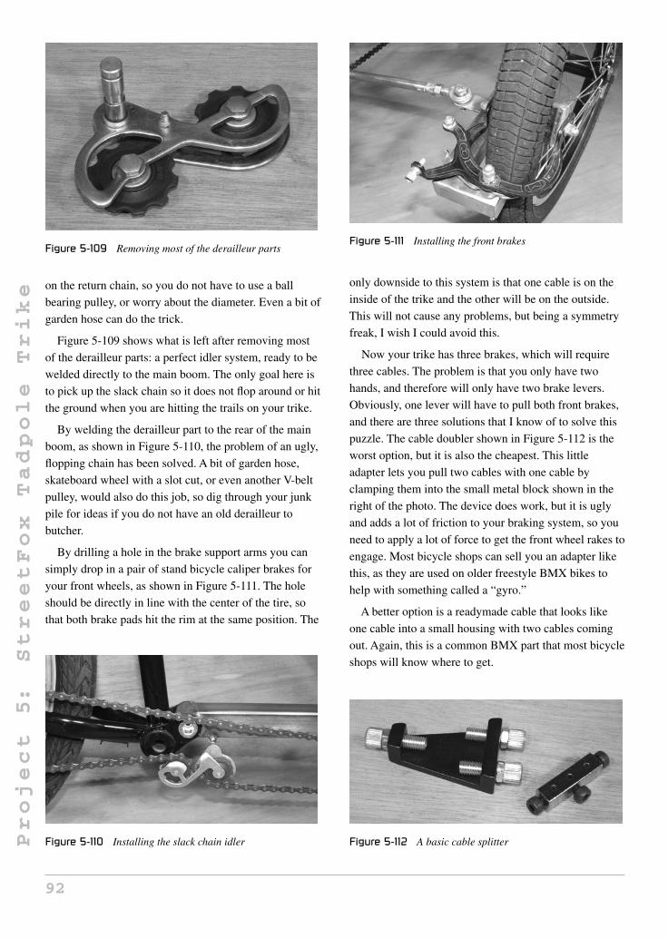
Project
5:
StreetFox
Tadpole
Trike
Figure 5-109 Removing most of the derailleur parts
on the return chain, so you do not have to use a ball
bearing pulley, or worry about the diameter. Even a bit of
garden hose can do the trick.
Figure 5-109 shows what is left after removing most
of the derailleur parts: a perfect idler system, ready to be
welded directly to the main boom. The only goal here is
to pick up the slack chain so it does not flop around or hit
the ground when you are hitting the trails on your trike.
By welding the derailleur part to the rear of the main
boom, as shown in Figure 5-110, the problem of an ugly,
flopping chain has been solved. A bit of garden hose,
skateboard wheel with a slot cut, or even another V-belt
pulley, would also do this job, so dig through your junk
pile for ideas if you do not have an old derailleur to
butcher.
By drilling a hole in the brake support arms you can
simply drop in a pair of stand bicycle caliper brakes for
your front wheels, as shown in Figure 5-111. The hole
should be directly in line with the center of the tire, so
that both brake pads hit the rim at the same position. The
Figure 5-110 Installing the slack chain idler
Figure 5-111 Installing the front brakes
only downside to this system is that one cable is on the
inside of the trike and the other will be on the outside.
This will not cause any problems, but being a symmetry
freak, I wish I could avoid this.
Now your trike has three brakes, which will require
three cables. The problem is that you only have two
hands, and therefore will only have two brake levers.
Obviously, one lever will have to pull both front brakes,
and there are three solutions that I know of to solve this
puzzle. The cable doubler shown in Figure 5-112 is the
worst option, but it is also the cheapest. This little
adapter lets you pull two cables with one cable by
clamping them into the small metal block shown in the
right of the photo. The device does work, but it is ugly
and adds a lot of friction to your braking system, so you
need to apply a lot of force to get the front wheel rakes to
engage. Most bicycle shops can sell you an adapter like
this, as they are used on older freestyle BMX bikes to
help with something called a “gyro.”
A better option is a readymade cable that looks like
one cable into a small housing with two cables coming
out. Again, this is a common BMX part that most bicycle
shops will know where to get.
Figure 5-112 A basic cable splitter
92

Project
5:
StreetFox
Tadpole
Trike
The best option, which is the one most used on tadpole
trikes, is a brake lever that is already set up to take two
cables. You might have to search the Internet for “dual
brake lever,” but there are several companies that make
them. With a dual brake lever, you can go about your
cabling as if you were cabling a standard bicycle.
I like a minimal seat on most of my vehicles, so the
plywood, foam, and fabric system tends to be my first
choice. You should really consider your seating wisely,
as everyone has a different opinion of what is
comfortable, and my system may not be the best for you.
My seat is 10 inches wide, with a base length of
10 inches, and a back height of 16 inches. The two parts
are shown being cut from some 3/8-inch thick plywood in
Figure 5-113. The rounded front and top were drawn by
tracing a dinner plate and a bucket lid.
To join the seat base to the seat back, I cut out a pair of
3-inch long pieces of 1/16-inch thick angle iron, and then
hammered them out to the angle of the seat. Figure 5-114
shows the two angle iron pieces with woodscrew holes
drilled into them.
Seat foam material should be comfortable to sit on, but
not so soft that it does nothing. Brown sponge foam is
Figure 5-113 Making a wooden seat
Figure 5-114 Seat board clamps
Figure 5-115 Adding foam to the seat
useless, and hard Styrofoam is no better than bare wood.
For my seat, I used some quality 1-inch thick seat foam
for the back of the seat, and some scrap 2-inch thick
packing material foam for the base. Both pieces of foam
were glued to the wood using adhesive spray
(Figure 5-115), and then trimmed along the wood using
the angle grinder.
As shown in Figure 5-116, the angle grinder makes
nice work of trimming the edge of the foam around the
edge of the wood. Be careful when grinding foam with
your grinder though, as the foam tends to grab the disc if
you try to take off too much at once or don’t hold the seat
securely when doing the work.
Seat padding is cut to fit, then stretched over the foam
to be stapled on the back of the seat. A real seat is sewn
together as a top cover with sides, but this “poor man’s”
upholstery system works equally as well and takes very
little time. I am not big on cutting corners, but if you ride
Figure 5-116 Trimmed foam ready for material
93

Project
5:
StreetFox
Tadpole
Trike
Figure 5-117 Adding the seat material
Figure 5-118 Stretch and staple
a lot, the seat material will wear out after a year anyhow,
so why get too fancy? Figure 5-117 shows the beginning
of the staple intensive journey.
If you stretch the material as you add each staple, you
can probably get most of the wrinkles out of the material.
A thicker material will be more difficult to work with, but
the results can be decent if you take your time.
Figure 5-118 shows how many staples keep the material
stretched around the corners to reduce the wrinkles.
After you fight with the material and empty your staple
gun, your material will likely be wrapped around the seat
to look like the seat shown in Figure 5-119. To cover up
the back of the seat, another piece of material can be cut
to the shape of the seat back and then stapled around its
edges. Plastic or very thin sheet metal can also be used to
hide the ugly staples and bare wood.
Because the seat was covered with one continuous
piece of material, the seam at the center was not perfect,
so I stretched a length of seat belt material around the
seam and stapled it to the wood. Figure 5-120 shows the
Figure 5-119 Completed seat upholstery
Figure 5-120 Securing the seat material
completed seat, which is not perfect, but not all that bad
either.
The backrest is made exactly like the rest of the seat,
and then covered with a piece of sheet metal
(Figure 5-121) to hide the wood and staples. I decided to
use metal rather than more staples and material to finish
up the backrest, because it would be much more visible
on the trike, so it should look professional.
Figure 5-121 Making the backrest
94

Project
5:
StreetFox
Tadpole
Trike
The last thing that needs to be done is trimming off the
excess main boom length. With your seat and cranks
installed, have the tallest rider sit on the trike (wearing
shoes) and set up the adjustable bottom bracket to the
correct place on the main boom. Now mark the boom,
leaving a few extra inches, and cut away any extra length
that will not be necessary. If you plan to add a fairing or
body later on, you may consider leaving the boom extra
long. Of course, you have to cap off the open end of the
boom tube just like you did with the seat tube, so it looks
clean and solid, as shown in Figure 5-122.
Waiting for paint and primer to dry is a painful
experience, but don’t lose patience and try to get your
trike on the road before the paint or primer has cured.
Primer often needs a full day to dry, and paint will not be
ready for handling for at least two days. If you read deep
into the application directions, you might even see that
proper paint curing time is a week or more, so the paint
will be easily scratched if you are not careful. I always
use department store spray cans, and usually the results
are very good if I can avoid the urge to assemble a wet
paint frame. Figure 5-123 shows the frame freshly
primed with the smaller parts painted and curing.
After two days of paint curing, I eagerly assembled the
entire StreetFox in about two hours. All bearings were
cleaned and greased, and new handlegrips, tires, cables,
and chain were installed. The completed bike shown in
Figure 5-124 really looked like a factory job, and it
handled as well as it looked!
A cycle with three brakes, two levers, and two shifters
has a lot of cable routing and planning that needs to be
done. I really don’t enjoy running cables, but this is a
Figure 5-122 Cutting down the excess main boom length
Figure 5-123 Primed and awaiting a paint job
Figure 5-124 Finally, we are ready to launch
necessary evil that has to be done, so take your time and
plan ahead before cutting any cable to length or adding
any zip ties. Avoid sharp bends in any cable, make sure
the wheels can turn from side to side without putting a
cable under great tension, and always replace any rusty,
frayed or stiff cables with new ones. Figure 5-125 shows
the plethora of cables running from the handlebars, as
well as the low budget one, into the two-brake cable
adapter.
Figure 5-125 The art of bicycle cable routing
95
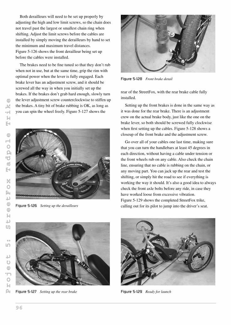
Project
5:
StreetFox
Tadpole
Trike
Both derailleurs will need to be set up properly by
adjusting the high and low limit screws, so the chain does
not travel past the largest or smallest chain ring when
shifting. Adjust the limit screws before the cables are
installed by simply moving the derailleurs by hand to set
the minimum and maximum travel distances.
Figure 5-126 shows the front derailleur being set up
before the cables were installed.
The brakes need to be fine tuned so that they don’t rub
when not in use, but at the same time, grip the rim with
optimal power when the lever is fully engaged. Each
brake lever has an adjustment screw, and it should be
screwed all the way in when you initially set up the
brakes. If the brakes don’t grab hard enough, slowly turn
the lever adjustment screw counterclockwise to stiffen up
the brakes. A tiny bit of brake rubbing is OK, as long as
you can spin the wheel freely. Figure 5-127 shows the
Figure 5-126 Setting up the derailleurs
Figure 5-127 Setting up the rear brake
Figure 5-128 Front brake detail
rear of the StreetFox, with the rear brake cable fully
installed.
Setting up the front brakes is done in the same way as
it was done for the rear brake. There is an adjustment
crew on the actual brake body, just like the one on the
brake lever, so both should be screwed fully clockwise
when first setting up the cables. Figure 5-128 shows a
closeup of the front brake and the adjustment screw.
Go over all of your cables one last time, making sure
that you can turn the handlebars at least 45 degrees in
each direction, without having a cable under tension or
the front wheels rub on any cable. Also check the chain
line, ensuring that no cable is rubbing on the chain, or
any moving part. You can jack up the rear and test the
shifting, or simply hit the road to see if everything is
working the way it should. It’s also a good idea to always
check the front axle bolts before any ride, in case they
have worked loose from excessive vibration.
Figure 5-129 shows the completed StreetFox trike,
calling out for its pilot to jump into the driver’s seat.
Figure 5-129 Ready for launch
96

Project
5:
StreetFox
Tadpole
Trike
Figure 5-130 The StreetFox is a beautiful machine
Figure 5-130 shows what can be done with a little hard
work and some commonly available bicycle parts. The
StreetFox looks and rides as good as any commercially
available trike, yet costs less than the shipping charge on
a factory unit. Speed and braking are very good, and
steering is comfortable and stable at any speed. Hill
climbing is not a problem due to the full range of
gearing, and the suspension makes for a very smooth
ride. Most people who encounter the StreetFox think it
was store bought, and give a strange look when told it
was made using hand tools from typical bicycle parts.
Kathy (Koolkat) hits the trails on her new StreetFox,
taking on pavement, steep hills, gravel roads, and bush
trails without any problems at all. Riding a comfortable
recumbent trike is so much easier on your body than an
upright bicycle, so the long journeys are truly enjoyable.
The wonderful scenery shown in Figure 5-131 is
Kakabeka Falls, near our home base in Northwestern
Ontario, Canada.
Figure 5-131 Kat’s new wheels
Figure 5-132 The journey is always better on a recumbent
Figure 5-133 The StreetFox Tadpole trike
Because you can ride in the most comfortable seated
position with never a need to put your feet down, a
recumbent trike is like your favorite living room chair
and the entire world is your television set. Often, we ride
our recumbent trikes to the beach or somewhere to have
a picnic, and we never have to bring chairs along!
Figure 5-132 is another shot of Kathy enjoying the
scenery at the Kakabeka Falls campground, with the
Kam River in the background.
We hope you enjoy building and riding your
recumbent trike as much as we have! The results of your
hard work will certainly be worth it, and nothing can
compare to the feeling of riding your own quality-built
recumbent trike. Figure 5-133 shows the StreetFox
taking another great photo in front of the tree line. We
hope to see your work or progress in the Atomic Zombie
forum, and would certainly be happy to post a photo of
your completed trike in our gallery for other builders to
see. The next project is another Atomic Zombie Extreme
Machines favorite—the DeltaWolf Racing trike—Brad’s
main ride these days.
97

Project
6:
DeltaWolf
Racing
Trike
Project 6: DeltaWolf Racing Trike
Riding a trike is completely different from riding a
normal two-wheeled bicycle. Obviously, balance is
effortless since the trike cannot tip over during “normal
riding,” so you can concentrate on the scenery in a more
relaxed state. And while stopped, you do not have to put
your foot down or shift your comfortable position. Load
carrying and trailer pulling are easier with a trike, and
you can climb hills at practically any speed without ever
having to get off and push your vehicle up the hill. Some
disadvantages of a trike include their weight, they tend to
look somewhat “unsporting,” and they can become quite
unstable around corners at any decent speed. Now, this is
not true for all trikes, but many of the “delta” style (two
wheels in the rear) trikes do take on an appearance of
large and clunky “granny shopper” vehicles. However,
the Atomic Zombie DeltaWolf aims to change all of the
shortcomings usually plaguing delta-style trikes.
Why did I choose to build a performance trike using
the delta layout (two rear wheels) rather than the
generally accepted tadpole layout (two front wheels)?
There were many factors that made this project come to
life. First, I really think that the two large rear wheels and
extremely low pilot’s seat look very sporty and unique.
Another reason was to have the ability to design a simple
hub/axle setup that would allow the use of 26-inch rear
wheels rather than the typical 20-inch size used on
almost all delta trikes. With 20-inch drive wheels, you
really limit your top speed due to the reduced rim radius
and final gear ratio, so what you end up with is a load
pulling machine. Another reason for this project was
because it could be done using easy-to-find parts, most of
which come from standard inexpensive scrap bicycles,
unlike a tadpole trike, which requires many expensive or
machined parts to build the complex front end and
steering system.
The final product is a very slick, one-of-a-kind, delta
trike low racer that not only performs as well as it looks,
but is a true joy to ride on the long hauls. There is very
little that can go wrong with the simple design of the
DeltaWolf, and the parts can be easily found at any
bicycle shop or from scrap bicycle parts. Like all my
designs, I like to keep things as simple and effective as
possible, requiring only common parts and basic tools,
and there is plenty of room for experimentation and
alternative design based on your style or needs. It’s best
to read the entire project over first before you start
cutting, so that you can understand where the next step
will be going and review all the alternative methods and
sources for parts.
Most of the DeltaWolf frame is made from 1.5-inch
mild steel square tubing with a 1/16-inch wall thickness.
This tubing can be ordered from any steel supplier and is
very easy to cut and weld. Steel suppliers like to rate
tubing wall thickness using a gauge number, so 1/16 wall
tubing will be called 16-gauge tubing, and although there
is a slight difference between the two, your best bet is to
tell them you want a length of 1.5-inch square tubing
with a wall thickness as close to .0625 inch (1/16) as you
can get. If you are a heavy rider (over 300 pounds), then
you should ask for the next size after that, which will
most likely be 14-gauge tubing, or .078-inch wall tubing.
Round tubing should be avoided for this project, as it will
yield a very flexible frame which will most likely be out
of alignment after all the welding is completed.
The drawing in Figure 6-1 shows what I will refer to
as the rear of the DeltaWolf. It is made from the same
1.5-inch square, 16-gauge (or 1/16-inch wall thickness)
tubing that will make up the entire main frame. This part
of the frame will determine the overall width of the final
trike, and it can be widened for larger riders if necessary.
As you can see, the overall width of the rear frame is
24 inches, and this is based on a typical adult shoulder
98Copyright © 2008 by The McGraw-Hill Companies, Inc. Click here for terms of use.
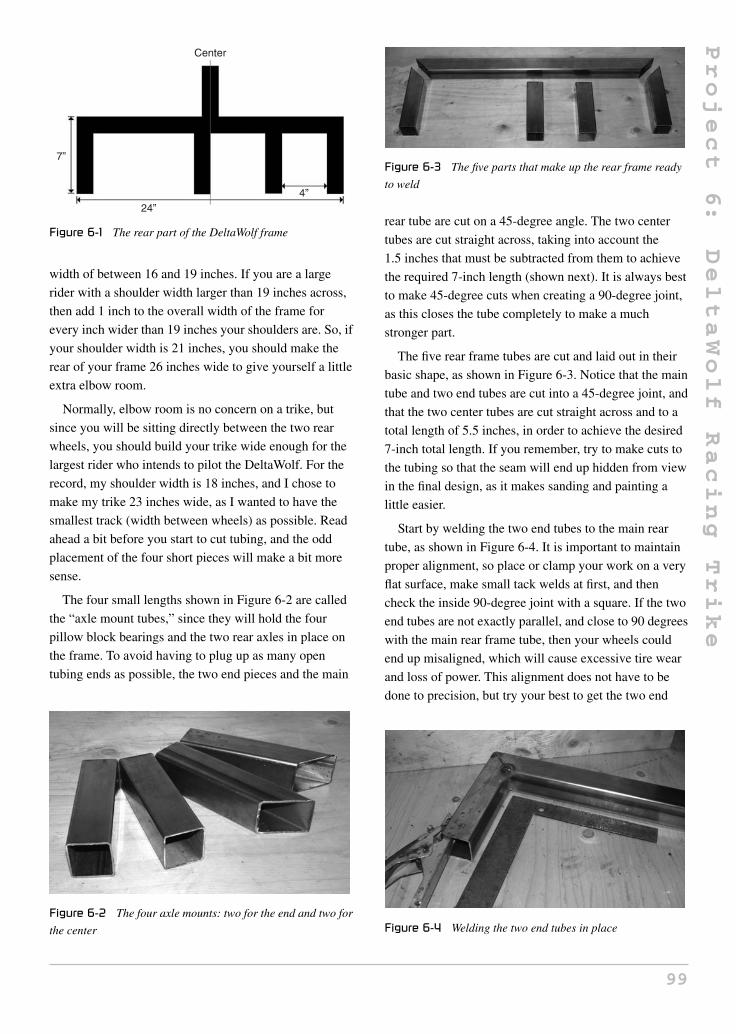
Project
6:
DeltaWolf
Racing
Trike
Figure 6-1 The rear part of the DeltaWolf frame
width of between 16 and 19 inches. If you are a large
rider with a shoulder width larger than 19 inches across,
then add 1 inch to the overall width of the frame for
every inch wider than 19 inches your shoulders are. So, if
your shoulder width is 21 inches, you should make the
rear of your frame 26 inches wide to give yourself a little
extra elbow room.
Normally, elbow room is no concern on a trike, but
since you will be sitting directly between the two rear
wheels, you should build your trike wide enough for the
largest rider who intends to pilot the DeltaWolf. For the
record, my shoulder width is 18 inches, and I chose to
make my trike 23 inches wide, as I wanted to have the
smallest track (width between wheels) as possible. Read
ahead a bit before you start to cut tubing, and the odd
placement of the four short pieces will make a bit more
sense.
The four small lengths shown in Figure 6-2 are called
the “axle mount tubes,” since they will hold the four
pillow block bearings and the two rear axles in place on
the frame. To avoid having to plug up as many open
tubing ends as possible, the two end pieces and the main
Figure 6-2 The four axle mounts: two for the end and two for
the center
Figure 6-3 The five parts that make up the rear frame ready
to weld
rear tube are cut on a 45-degree angle. The two center
tubes are cut straight across, taking into account the
1.5 inches that must be subtracted from them to achieve
the required 7-inch length (shown next). It is always best
to make 45-degree cuts when creating a 90-degree joint,
as this closes the tube completely to make a much
stronger part.
The five rear frame tubes are cut and laid out in their
basic shape, as shown in Figure 6-3. Notice that the main
tube and two end tubes are cut into a 45-degree joint, and
that the two center tubes are cut straight across and to a
total length of 5.5 inches, in order to achieve the desired
7-inch total length. If you remember, try to make cuts to
the tubing so that the seam will end up hidden from view
in the final design, as it makes sanding and painting a
little easier.
Start by welding the two end tubes to the main rear
tube, as shown in Figure 6-4. It is important to maintain
proper alignment, so place or clamp your work on a very
flat surface, make small tack welds at first, and then
check the inside 90-degree joint with a square. If the two
end tubes are not exactly parallel, and close to 90 degrees
with the main rear frame tube, then your wheels could
end up misaligned, which will cause excessive tire wear
and loss of power. This alignment does not have to be
done to precision, but try your best to get the two end
Figure 6-4 Welding the two end tubes in place
99

Project
6:
DeltaWolf
Racing
Trike
Figure 6-5 The end tubes are completely welded and ground
tubes as parallel as possible so they look perfect from a
visual inspection. If your 45-degree cuts were a little off,
just tack weld the ends of the joint, and tap the two parts
to 90 degrees with a small hammer; you can later fill in
the gap with welding rod.
Weld the top joint at both end tubes before you flip the
part over, so that all three pieces will remain perfectly
flat on whatever surface they are placed. Once square,
the far outer end joints can be welded followed by the
opposite (bottom) side of the joint. Save the inside corner
welds for last, and make them with a little heat and
welding rod as necessary in order to reduce distortion.
Once you have the two axle tubes welded to the ends
of the main rear frame tube, clean and grind the welded
area as much as necessary, as shown in Figure 6-5. Avoid
taking off too much weld material, or else you will
weaken the joint. There should be a small smooth hump
over the welded area, rather than a low spot after you are
done grinding with whatever finishing disc you prefer.
The reason we are cleaning up the welded area at this
stage in the build is because the part is easy handled on
the workbench, and this makes the job much easier than
if it were a complete frame.
The DeltaWolf is driven by a freehub installed on the
left-side axle, and braked using a disc brake installed on
the right-side axle (or both axles if you so choose). For
this reason, the drive-side axle mount tube shown tack
welded in place in Figure 6-6 needs to be placed on the
left side of the center line (refer to the drawing in
Figure 6-1). As you can see in Figure 6-6, I made a
marker line on the main rear frame tube at the exact
center, then placed the tube directly to the left of this line,
making sure it was at 90 degrees to the main rear frame
tube before tack welding. Since the multi-speed freehub
will be connected directly to the end of the left-side axle,
Figure 6-6 Installing the drive-side axle mount tube
this places the freehub in a perfect place for alignment
with the front-drive chain ring on the crank set; in other
words, it creates a transmission much like that on any
normal bicycle.
The reason the left wheel is chosen as the drive wheel
is because all freehubs have the ratchet set up this way,
and it would require some very complex or expensive
custom built parts in order to drive the right wheel.
Driving both wheels is an even more complex task,
requiring a special differential which would greatly
increase both the weight and cost of this project, yet add
no real benefit. Most delta trikes only drive the left rear
wheel, and this is completely unnoticeable by the rider
while riding under normal conditions. On taller “granny
style” delta trikes, there is a tendency to have the drive
wheels slip a little bit when accelerating around a
lefthand turn, since the high center of gravity will make
the left wheel try to lift away from the road, but since
these trikes are not built for any real speed, this is
not a real problem. On the DeltaWolf, the rider is placed
so low that the center of gravity is such that a wheel lift
is almost impossible under all but the most extreme
circumstances, and drive wheel slipping is not an issue
at all.
The drive-side axle mount tube is completely welded
and ground clean using the same careful methods as
before to ensure alignment at 90 degrees. The last tube to
be installed in the rear frame is the brake-side axle mount
tube, and it is placed 4 inches away from the tube on the
right side of the frame so that there is a 4 inch distance
between them, as shown earlier in the drawing in
Figure 6-1. This 4-inch space will be used to place the
disc brake hardware, and will leave plenty of room for
whatever make and model brake you choose to install.
Tack weld, then check alignment carefully before
completely welding any of the joints, and don’t be afraid
to cut and reweld if you find a problem—this is one of
100

Project
6:
DeltaWolf
Racing
Trike
Figure 6-7 Welding the brake-side axle mount tube in place
Figure 6-8 Completed rear frame section
the most important parts of the entire frame, so it should
be done to the best of your abilities.
Once completely welded, ground, and cleaned, your
rear frame section will look like the one shown in
Figure 6-8. All of the four axle mount tubes will be
perfectly parallel, and there should be a very close
90-degree angle between all the joints. If you place the
part on a flat surface so that the open ends of the axle
mount tubes face the ceiling, you may notice a very
slight bow shape to the frame. This is due to the
distortion caused by heat on the welded area of the inside
joints. Do not worry too much about this, as I have
worked this out in advance, and the way the axle is
installed later on will take care of this problem,
producing a perfectly aligned set of rear wheels.
Now that you have made the rear part of the frame, the
rest of the main frame will come together quickly, as
there are only three more tubes needed: the main boom,
the seat tube, and the front tube. Shown in Figure 6-9 is
the main boom (the longer tube) and the seat tube (the
tube your seat will lean against). The length of the main
boom will allow riders from 5 feet in height to 6'-6", and
if you are taller than that, just add a few inches to the
recommended 44-inch length. The 3-inch bit of the main
boom sticking out past the seat tube joint is there to allow
mounting of the drive chain pulley. Again, read ahead a
bit to understand how the main frame will come together
before cutting any tubing, just in case you want to make
your own modifications or additions.
Figure 6-9 The main boom and seat tube drawing
Figure 6-10 Cutting the main boom and seat tube
Cut the main boom and seat tube from the same
1.5-inch square tubing as the rest of the frame, as shown
in Figure 6-10. You can either mark and cut the angles
directly from your length of tubing, or simply cut both
tubes off at their respective lengths, 44 inches and
13 inches, dealing with the angles for each piece later to
make working with the tubing a little easier. If your cuts
are a bit off the mark, simply file or grind the ends of the
tubing until your angles are within a degree or two of the
required dimensions. Again, you do not need
precision—just try to get as close as you can to the
correct lengths and angles—a half inch too much or too
little tubing will not throw this part of the frame out.
The seat tube is welded directly to the main boom so
that there is a 3-inch length of tubing extending past the
top rear joint, as shown in Figure 6-11. A marker line
around the tube makes this easy to see when you are
setting up both tubes to be welded together. I like to tack
weld the top of the joint (where your butt will be) first so
that I can doublecheck the angle and alignment before
going further. If the angle is good, the two parts can then
be held in a vice to ensure alignment, as you weld across
the top and rear of the joints. The sides of the joint are
welded last, by welding a small portion at a time and
then switching sides to minimize distortion from heat.
101

Project
6:
DeltaWolf
Racing
Trike
Figure 6-11 Getting ready to join the main boom and seat tube
Figure 6-12 Main boom and seat tube become one
In Figure 6-12, I have completed the welding of the
main boom and the seat tube. Grinding this joint will not
be necessary since it will be completely hidden from
view by the seat. I only grind welds that are highly
visible; this way you do not inadvertently weaken the
joint. By the way, this is the most stressed joint in the
entire trike, and to further strengthen it, a gusset will be
added later in the build.
The rear part of the frame will now join the main part
of the frame by welding it directly to the top of the seat
tube, as shown in Figure 6-13. The two parts will form a
perfect T-shape, with the seat tube meeting the rear frame
tube directly in the center. Start by tack welding only a
single spot on the top and bottom of the joint, as shown
in Figure 6-13—this will make it easy to get that perfect
90-degree angle between the rear frame tube and seat
tube.
As shown in Figure 6-14, the 90-degree angle between
the seat tube and rear frame tube is very important, in
Figure 6-13 Joining the rear of the frame to the main frame
Figure 6-14 Cleaning the welded area is easy at this stage
order to keep the rear wheels aligned with the front
wheel. Check both sides using a square and tap the pieces
into perfect alignment with a small hammer if necessary.
Weld a little more of the top and bottom joints, checking
alignment as you go, but do not weld the side of the joint
yet, or your frame will end up out of alignment. The side
of the joint will be done after the two truss tubes are in
place, as shown in the next few steps. Your goal is to set
up the main frame and rear frame to a perfect 90 degrees,
using a few solid tack welds so that you can install the
truss tubes. Once the truss tubes are in place, welding the
sides of the joint can be done without any alignment
problems.
The truss tubes form a pair of triangles between the
seat tube on the main frame and the rear frame tubing,
which makes the frame extremely strong and resistant to
bending. The frame would certainly be strong enough to
support your weight without these tubes, but if you ever
102

Project
6:
DeltaWolf
Racing
Trike
Figure 6-15 Two truss tubes cut from 1-inch square tubing
hit one of the rear wheels into a curb or wall with enough
force, the rear of the frame may bend at the seat tube
joint. These two small tubes (Figure 6-15) will not only
make the frame extremely durable, but they will also
keep the tubes straight while you complete the welding
process. These tubes are not made out of the same
1.5-inch diameter tubing as the rest of the frame, since
they are only needed for their tensile strength and will
not carry any weight. Thinner tubing from 1 inch down
to 3/4 inch will be fine, and this tubing can take any shape
you like.
The angles needed at the ends of each tube are found
by measuring the distance from the tube wall just below
the seat tube and main boom joint to the corner of the
rear frame tube. The exact length and angle measurement
is not given because it depends on the width of your
frame, and is much easier to figure out by simple trial
and error rather than trying to get it perfect on the first
try. I like to take a rough measurement, cut an inch or
two longer than necessary, and then grind the end down
until it fits perfectly. To make the second tube, transfer
the length via a marker and cut again.
If your truss tubes are square, then try to get them cut
so that the flat side faces the same direction as the rest of
the frame tubing, as this just looks proper. It’s best to cut
both truss tubes, then tack weld them in place so that
they can be visually inspected before completely welding
them, just in case one tube is too long or too short.
Figure 6-16 shows the first truss tube being tack welded
in place. I am using thin 3/4 tubing purchased from a local
hardware store, but many sources of tubing can be used,
including tubing from furniture or even 3/4 thin walled
electrical conduit.
Figure 6-16 Installing one of the truss tubes
Figure 6-17 Both truss tubes tack welded in place
Figure 6-17 shows the two truss tubes tack welded in
place and ready for the final welding. Don’t forget to do a
thorough visual inspection before welding, or you will be
spending a lot of time with that cut-off disc later!
Actually, if both truss tubes are the same length, it’s
almost impossible to end up with a misaligned frame at
this point.
The truss tubes can now be welded in place, as shown
in Figure 6-18. You may not be able to get the welding
rod into the joints that form the small angles top and
bottom, but this is not a problem as long as at least three
sides of the tube at each end get welded. Once you have
the truss tubes securely welded in place, you can finish
the welding between the inside joint of the rear frame
and seat tube, without any risk of misalignment due to
welding heat distortion. The rear of the frame is almost
complete, but those ugly open-ended tubes must be
103

Project
6:
DeltaWolf
Racing
Trike
Figure 6-18 Completing the rest of the rear frame welding
capped off or your completed DeltaWolf will have
“home built” written all over it. Open tubing is not only
very unprofessional looking, but it leaves very sharp
edges that can cut a person handling the trike, and leaves
your frame open for attack from moisture or any critter
that feels like taking up residence inside the tubing. Let’s
cap those tubes!
It may seem like a lot of work to cap off those open
tubes, but in reality it is as simple as running a cut-off
disc along a small sheet of 16-gauge sheet steel a few
times, then spending a few minutes with your welder and
grinder. There are plastic plugs you can get to cap off the
tubing, but those will not enhance the strength of the
tubing, and this is important since the pillow block
bearings will be held very close to the open ends of the
tubing. Without the steel caps welded in place, the force
of the nut and bolt at the end of the tube may crush the
walls. Figure 6-19 shows the bit of scrap steel I used to
cut my five 1.5-inch end caps from. The sheet metal
should be as close to the thickness of the tubing wall as
you can find, so 16-gauge sheet metal will fit the bill
perfectly. Cut the squares any way you like. My favorite
method is to run a cut-off disc along the marker lines,
then bend the parts back and forth until they snap apart.
There’s nothing special about this job; it just takes a
few minutes of light welding to seal the tubing
Figure 6-19 Five 1.5-inch squares to be cut
Figure 6-20 Welding the end caps in place
Figure 6-21 Capped tubing looks so much more professional
(Figure 6-20). Before you cap off the last tube on the rear
frame, give it a shake to release any slag or junk that may
have fallen into the tube while you were working.
Figure 6-21 shows the welded and ground tubing ends,
which will now keep your tubing sealed from the outside
world and remove all sharp edges from your frame. I
usually rough grind the area with a heavy grinder disk,
then finish the cleanup with a sanding disk to avoid
taking off too much weld material. The results are really
worth the extra effort.
Because the rider will be sitting directly over the joint
that connects the main boom to the seat tube, some
reinforcement may be necessary depending on the weight
of the rider. If you weigh less than 150 pounds, you could
probably just skip the gusset altogether, but considering
it is simply a bit of 1.5-inch square tubing that adds
almost no extra weight to the trike, it’s a good idea to
include it anyway. This gusset will transfer some of the
104
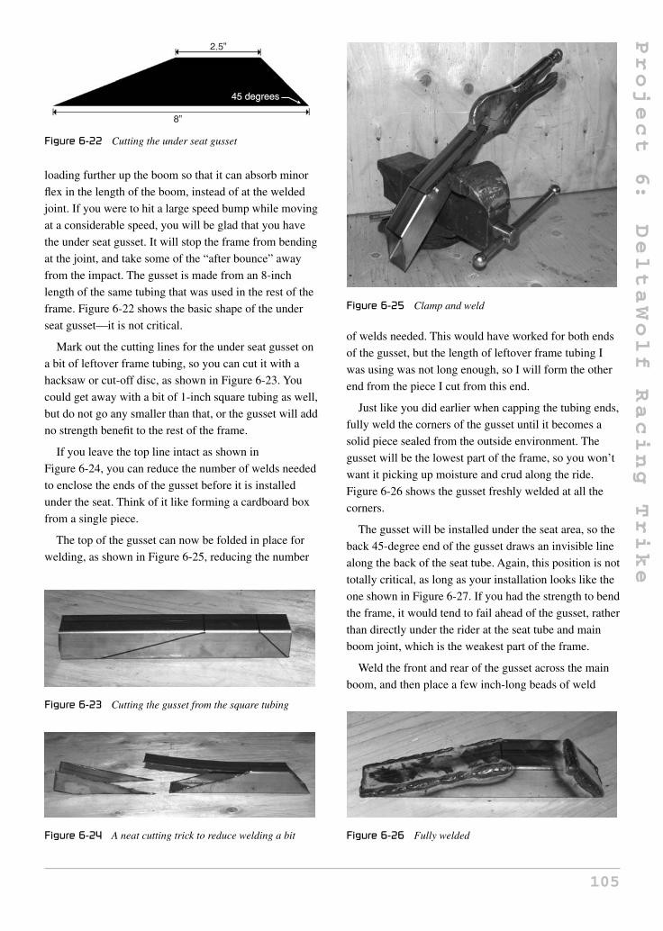
Project
6:
DeltaWolf
Racing
Trike
Figure 6-22 Cutting the under seat gusset
loading further up the boom so that it can absorb minor
flex in the length of the boom, instead of at the welded
joint. If you were to hit a large speed bump while moving
at a considerable speed, you will be glad that you have
the under seat gusset. It will stop the frame from bending
at the joint, and take some of the “after bounce” away
from the impact. The gusset is made from an 8-inch
length of the same tubing that was used in the rest of the
frame. Figure 6-22 shows the basic shape of the under
seat gusset—it is not critical.
Mark out the cutting lines for the under seat gusset on
a bit of leftover frame tubing, so you can cut it with a
hacksaw or cut-off disc, as shown in Figure 6-23. You
could get away with a bit of 1-inch square tubing as well,
but do not go any smaller than that, or the gusset will add
no strength benefit to the rest of the frame.
If you leave the top line intact as shown in
Figure 6-24, you can reduce the number of welds needed
to enclose the ends of the gusset before it is installed
under the seat. Think of it like forming a cardboard box
from a single piece.
The top of the gusset can now be folded in place for
welding, as shown in Figure 6-25, reducing the number
Figure 6-23 Cutting the gusset from the square tubing
Figure 6-24 A neat cutting trick to reduce welding a bit
Figure 6-25 Clamp and weld
of welds needed. This would have worked for both ends
of the gusset, but the length of leftover frame tubing I
was using was not long enough, so I will form the other
end from the piece I cut from this end.
Just like you did earlier when capping the tubing ends,
fully weld the corners of the gusset until it becomes a
solid piece sealed from the outside environment. The
gusset will be the lowest part of the frame, so you won’t
want it picking up moisture and crud along the ride.
Figure 6-26 shows the gusset freshly welded at all the
corners.
The gusset will be installed under the seat area, so the
back 45-degree end of the gusset draws an invisible line
along the back of the seat tube. Again, this position is not
totally critical, as long as your installation looks like the
one shown in Figure 6-27. If you had the strength to bend
the frame, it would tend to fail ahead of the gusset, rather
than directly under the rider at the seat tube and main
boom joint, which is the weakest part of the frame.
Weld the front and rear of the gusset across the main
boom, and then place a few inch-long beads of weld
Figure 6-26 Fully welded
105

Project
6:
DeltaWolf
Racing
Trike
Figure 6-27 Installing the gusset
Figure 6-28 Only a few short welding beads are needed
along the sides, as shown in Figure 6-28. There is no
need to weld the entire length of the gusset, as this area
will never be under any stress. You can also bypass the
grinding process, as the gusset will remain hidden under
the seat when the DeltaWolf is completed.
Now that the rear frame is joined to the main frame
(Figure 6-29), you can start creating the rear hub/axles.
The front part of the frame will be done after the rear
wheels are installed because it is easier to set up the
proper head tube angles and placement. Completing the
front end at this time could leave your ground clearance
too much or too little if the angle between the main boom
and front tube are not done correctly. By having the rear
of the bike standing on its wheels, this error will be
easily avoided.
One of the most unique features of the DeltaWolf is
that it has no rear hubs. The flanges that hold the spokes
Figure 6-29 The rear and main frame completed
are actually part of the rear axles, so this greatly
simplifies the design, saves the builder a lot of money
that would otherwise go to purchasing expensive
aluminum hubs to be machined, and it also gives us the
ability to widen the hub for use with a 26-inch rear rim
rather than the typical 20-inch size. On a normal 26-inch
rear wheel hub, the flanges are much closer together, so
the wheel would not be able to withstand the great deal
of side loading given to it on a trike, and may tend to
bend or collapse. The wider the hub, the more lateral
strength you put into the wheel, so this is how we are
able to use a full-sized, 26-inch rear wheel on the
DeltaWolf rather than being forced into the smaller size.
A smaller drive wheel means less top speed and a much
harsher ride, so this is a real plus.
I came up with the hub/axle combination when I was
working out how to build a delta trike without being
forced to use 20-inch rear wheels. There were a few
readymade options for good strong 36-spoke hubs, but
not only were they very expensive, they were designed
for a 1-inch thick axle, which is way too much steel for a
single-rider trike. Those hubs were made for pedicabs
designed to carry two or more adults and the pilot, so that
option was no good. I thought about having a mountain
bike hub drilled to fit the 5/8 axle I planned to use, but
now I was into $150 per hub, plus the time it would take
to have them machined. Even after that, the quest
remained as to how to permanently affix the machined
hubs to the axles—keyway? Ugly bolt or cotter pin?
I thought there had to be a better way, and yes there was.
Why have a hub at all? An expensive machined hub
bolted to an axle does nothing at all—it is wasted
material. All that was needed was the flanges to hold the
spokes, and even if I made them from steel, they would
still end up weighing less than a complete hub machined
and fit to the axle. Since a hub flange was nothing more
than a washer, this seemed like a really good idea. As
shown in Figure 6-30, I had the machine shop slice off
four 1/8-inch thick disc from a bit of 2.5-inch diameter
steel stock, and then 5/8-inch holes were drilled through
the center. The discs are actually slightly less than
2.5 inches in diameter, but anything close to 2.5 inches,
give or take 1/4 inch either way, would be just fine.
Although the four flanges only cost me $50 to have done
at the machine shop, you could actually do this part
without any machined parts at all, using a pair of hacked
steel bicycle hubs, and I will show you this method
106

Project
6:
DeltaWolf
Racing
Trike
Figure 6-30 Creating the DeltaWolf hub flanges
as well. Personally, I think the machined flanges are the
best way to go, since they will result in a nice, flat, outer
flange that does not look like a hacked bicycle
hub—something that seems to plague many delta trikes.
Read the entire axle/hub section that follows, so you can
see how this is done before choosing which method
to use.
The four flange discs are made of mild steel 1/8-inch
thick and approximately 2.5 inches in diameter. The hole
in the center is 5/8 inch in diameter so that the discs will
fit snugly onto the 5/8 axles used on the DeltaWolf. If you
decide to have these discs made at a machine shop, just
print out this text and/or photo, or tell them you want four
2.5-inch diameter washers with a 5/8 hole in the center of
each with a thickness of 1/8 inch. Also tell them that you
plan to weld the discs, just in case they have some exotic
or hardened steel; mild steel is what you want. The 18
spoke holes in each disc are drawn using a compass or by
punching through a template, as shown in Figure 6-31.
There should be no less than 1/8 of an inch between the
Figure 6-31 Punching the spoke holes in the flange discs
edge of the disc and the closest edge of the spoke hole to
make the disc as strong as possible. In other words, the
meat between the edge of the flange and the hole should
be about the same diameter as the spoke hole. Have a
look at how a normal bicycle hub is made, and you can
see this. If you are not a compass expert, or do not have a
computer program that can make this template, then you
can download the image from our website
atwww.atomiczombie.com/support/dwhub.jpg—you can
resize it in your favorite graphics program and print it out
as a guide.
You will need to resize the pattern by trial and error
since all printers will print using different sizes, and the
original file will most likely be much too large. The
circle drawn in the center of the pattern, as shown in
Figure 6-31, is used as a guide to tape the pattern onto
the disc for punching. I hold the pattern and disc up to a
bright light so the light shines through the pattern,
allowing me to tape the pattern directly to the center of
the disc. The resulting punched disc, as shown on the
right of Figure 6-31, is very accurate. If your machine
shop buddy “owes you one,” or you despise drilling
holes, you could pay him or her to do this as well, but
where’s the fun in that?
The spoke holes will be drilled using a 7/64-inch drill
bit. It may seem like a lot of work to drill 72 small holes,
but in reality, this entire job only takes about an hour
depending on the quality of your drill and bits. I am a
minimalist and do not own a drill press, so I do this work
using a hand drill, which is why the disc is held to a
board in Figure 6-32 by a pair of wood screws. Drill and
turn, drill and turn, drill and turn—I am truly thankful
that I do not manufacture bicycles for a living or this
Figure 6-32 Drilling the spoke holes
107

Project
6:
DeltaWolf
Racing
Trike
hobby would quickly turn into a real chore! My hand
drill was getting a little warm by hole 72, but I made it
non-stop in less than an hour. If one of the spoke holes is
slightly off center, do not fret, as you will be able to
adjust this during the spoking process, and it will not
affect the wheel in any way.
If you look closely at a standard bicycle hub, you will
notice that the holes are very slightly beveled on the
inside, so that the spoke bend is not subjected to a very
sharp edge as it exits the spoke hole. This process can be
recreated by simply running a 1/8-inch drill bit lightly into
each hole for about two seconds. The result will be a
beveled hole, like the one shown in Figure 6-33 on the
right disc. Do not put any pressure on your drill when
doing this operation, or you may drill into the hole,
which is why a hand drill may be the best tool to use
when doing this operation. The goal is to smooth off the
sharp edge without making the hole any wider. Do this to
both sides of all the holes in each flange.
Now that your hub flanges are completed, you will
need to create the two rear axles so they can be welded in
place. The DeltaWolf has two rear axles made of 5/8-inch
diameter mild steel. You will need an axle at least 8
inches wider than the overall width of the trike’s rear
end, since we are going to work with a single axle at first.
If you have a 24-inch wide trike, then ask the machine
shop for a 32-inch mild steel 5/8-inch rod. It is important
to let them know you will be welding the rod, as there are
different hardness rods available, and they may
automatically assume you want a harder steel rod. If the
steel is too hard, it may crack or weaken from the
welding process.
Figure 6-34 shows the 31-inch axle (my trike is
23 inches wide), and a pair of 5/8-inch pillow block
Figure 6-33 Drilled (left) and beveled (right)
Figure 6-34 One of the rear axles and a set of pillow block
bearings
bearings that will bolt onto the rear frame. You will need
four of these pillow block bearings to hold the two axles
to the trike, and these are available in many shapes and
styles. The ones shown in Figure 6-34 are simple steel
clamp housing pillow blocks, but they are available in
cast iron, cast aluminum, and many other mounting
styles. The important thing is that they do not weigh a ton
and can be easily fastened to the 1.5-inch square tubing
using a pair of bolts. The axle center should end up no
more than 2 inches away from the end of the axle
mounting tubes, or you will not have room for your disc
brake.
As shown in Figure 6-35, the pillow block bearings are
mounted to the axle mounting tubes so that the end of the
pillow block is as close to the end of the tube as possible
without hanging over. This places my axle center within
1.75 inches of the end, which gives plenty of room for
clearance of the disc brake. If you are not sure if your
bearing will allow clearance for the disc brake between
the sides of the rear frame tube, just hold the disc roughly
in place over the axle to check. Most pillow block
Figure 6-35 Mounting the pillow block bearings
108

Project
6:
DeltaWolf
Racing
Trike
Figure 6-36 The single axle held in place by the bearings
bearing housings will be just fine, but it doesn’t hurt to
check before drilling the holes. To get the hole centered,
simply drop the pillow block housing on the frame tube,
mark the hole with a marker, and then punch the center.
Do this on both sides of the frame, and then drill the
appropriate sized hole for whatever bolt you need to
fasten the pillow block to the frame. The pillow blocks
are placed as far to the end of the tubing and as far to the
outer edges as possible, as shown in Figure 6-35.
The reason I chose to work with a single axle at first is
because any frame alignment problems will not translate
into the two rear wheels being out of alignment. With a
single axle held by the outer bearings, as shown in
Figure 6-36, the other two pillow block bearings can be
placed on the frame to mark their hole centers, while
ensuring that all four bearings are in perfect alignment. If
you tried to install the inner bearings in any other way,
your rear wheels may have toe-in or toe-out
misalignments that will cause excessive tire wear and rob
you of your top speed. Why not leave the axle solid and
just mount the freehub and brakes to it like it is, you ask?
If you did that, you would create a trike that would not
go around corners. Since the rear wheels turn at different
speeds as you corner, the solid axle would try to make
one wheel skid around the corners, and since so much of
the weight is at the rear, this would most likely cause the
front wheel to just skid along in a straight line, no matter
how far you turned it. If you did manage to get the bike
to turn a corner with a solid axle, the effort that this
would take would make hill climbing seem like an easy
task. To drive both rear wheels, you would need a geared
differential, which is a complex setup that splits the
difference between both wheels. This is unnecessary and
Figure 6-37 Marking the inner bearing holes
would increase weight and complexity to ridiculous
proportions.
With the long axle securely held in place by the outer
pillow block bearings, as shown in Figure 6-37, place the
two inner bearings into the correct position on the drive
and brake mounting tubes, and then mark the holes for
drilling like you did before. Notice that the two inner
bearings are as close to the inner ends of the tubing as
possible, which is opposite to the outer bearings’ position
on the tube. Mark each site of the frame for drilling by
bolting the axle onto each side of the frame to mark the
center holes.
Figure 6-38 shows all of the pillow block bearings
mounted to the frame using the appropriate sized bolts.
I chose to use self-locking nuts just to be safe, but since
the axle is going to be removed a few more times before
permanent installation, I placed a few spaces on the bolt
to avoid locking it on, as this would make removing the
nut a little bit of a chore. With all the pillow block
bearings held tight, you should be able to slide the axle
right out by pulling at one end—this is proof that both
rear wheels will be installed with almost perfect
alignment. Notice that I have more than 4 inches of axle
sticking out past the ends of the frame, which gives
Figure 6-38 All of the bearings mounted to the frame
109

Project
6:
DeltaWolf
Racing
Trike
Figure 6-39 Marking the axle for cutting
plenty of meat to work with when it comes time to create
the built-in 3.5-inch wide hubs.
Now that you know your two axles will be perfectly
aligned, you can cut them apart to create a left and right
side. Since both axles have completely different lengths,
you can’t just find the center and cut; you have to find the
center between the two inner bearings. As shown in
Figure 6-39, I measured the distance between the two
center bearings and drew a line by turning the axle
around while holding a marker in place. Make sure that
there is an equal length of axle sticking out past the outer
bearings on the ends of each frame before you draw
this line.
Figure 6-40 shows the freshly separated left and right
axles after cutting with a cut-off disc. I like to cut the
axles while they are held on by the pillow block bearings,
as this makes the job easy. Just hold the cut-off disc in
place and turn the axle as you cut through it. You will
want to buff or slightly grind the rough ends off the
freshly cut axles after cutting so that the bearings can
slide on and off easily. The freshly cut ends are razor
sharp and will make sliding the bearings onto the axle
Figure 6-40 Cutting the axle into a left and right side
Figure 6-41 Tack welding one of the hub flanges in place
difficult. Congratulations! You now have two perfectly
aligned rear axles—a job that would have been very
difficult to do properly using any other method. If there
was any bowing on the main rear frame tube after
welding the four small tubes in place, then this will no
longer be an issue in rear axle alignment.
It’s now time to integrate the flanges with the axle to
create the axle/hub on both the drive- and brake-side
axles. As shown in Figure 6-41, this is done using the
frame as a stand, so that you can simply spin the axle in
order to check flange alignment as you weld. Before you
make the first tack weld, it is important to note that you
should never place your welding ground clamp in any
place that would cause the current to flow through the
bearing into the weld area. If you clamped to the frame,
the current would have to travel through the inner and
outer bearing races, and through the actual ball bearings,
in order to complete the circuit, which will damage the
bearings. Since each ball bearing only contacts the inner
and outer races by a very small surface area, the high
welding current will create a pit in the bearing races,
causing what would seem like years of wear on the
bearing. Place the ground clamp on the axle, not the
frame, and you will avoid this problem. Start with a small
tack weld, as shown in Figure 6-41, leaving about 1/16 of
an inch of axle sticking out past the hub flange to make
welding easier. Once the tack weld has cooled, remove
the ground clamp and spin the axle to check alignment.
It is very easy to see any misalignment of the flange as
you turn the axle, and this is corrected using a few small
taps of a hammer along the disc until it spins true. A very
slight wobble is not a big deal in the end, since the
spokes will correct this, but do try to get the disc
spinning as true as you can while it is easy to manipulate.
110

Project
6:
DeltaWolf
Racing
Trike
Figure 6-42 The hub flange is now aligned to the axle
Once you have tapped the flange into alignment from
the previous step, add another tack weld directly opposite
to the first tack weld, and then repeat the spinning and
tapping process to true the disc back up. Repeat this
process until your hub flange looks like the one shown in
Figure 6-42, with four decent tack welds holding the
flange to the axle in as perfect alignment as you can get
it. Once this is done, you can remove the axle and weld
the opposite side joint, with little fear of pulling the disc
out of alignment with the axle.
The inner side joint can be welded around the entire
joint, as shown in Figure 6-43, now that the four solid
tack welds are securing the flange to the axle. I do this
welding in four passes, switching to the opposite site of
the axle just as a precaution against distortion due to
heat, which is a good practice to get into when welding.
Once you are done welding the entire distance, place the
axle back into the pillow block bearings and give it a spin
to check alignment. A very slight wobble is not a big
Figure 6-43 Inner joint fully welded
Figure 6-44 Completely welded flange and axle
deal, but if you think there is too much misalignment,
a few whacks of the hammer may still cure this. Any
misalignment less than the thickness of the actual disc
will be acceptable and will have no effect on the
wheel-spoking process, nor will it show in the final build,
so do not spend too much time and effort trying to get the
disc spinning with “military accuracy.”
Go ahead and weld completely around the front side of
the joint now that the rear joint is solid. This can be done
with no fear of heat distortion, since the disc cannot
move at all now. As shown in Figure 6-44, a generous
amount of weld is placed around the joint to ensure that
there will be no pinholes after the face is ground flush in
the next few steps. The final hubs will be very cool
looking units once the ends are ground flush, leaving no
visible line between the flange face and the axle. If you
look at many production trikes, there is a huge, gangly
looking bolt sticking out past the hub face, in order to
secure the hub to the axle or, even worse, a locking pin.
These integral hubs avoid that “ I made this fit” look.
Before you start on the inner flanges, have a look at the
completed hub in Figure 6-45, and you will notice that
the holes on each opposing flange are offset by each
other. If you place a rod or spoke through one of the
holes, it will not enter a hole on the opposing flange; it
will hit the space between the holes. Every bicycle hub is
manufactured like this, even the cheap steel units, and
this is an important thing to do for wheel strength once
the spokes are in place. Keep this point in mind when
you start tack welding the inner flanges to the axle.
A spoke or small welding rod can be used to check this,
like I have done in Figure 6-45.
111

Project
6:
DeltaWolf
Racing
Trike
Figure 6-45 Holes in opposing flanges are offset by each
other
Figure 6-46 Repeating the process for the inner flanges
As shown in Figure 6-46, the same process used to
mount the first flange to the axles is used to mount the
inner flanges as well, but do not forget two important
points: always place the ground clamp on the axle, not
the frame, and make sure that each flange has the holes
offset by one another. Other than that, tack, hammer,
tack, hammer until you have completed all of the
welding. The distance between the flanges will be
3.5 inches, as measured from the inside of each
face—this makes for a much stronger hub that can take
the heavier load demanded by a trike. A typical rear
bicycle hub has the flanges at 2 inches apart, so our
3.5-inch wide hub will be much stronger.
Figure 6-47 shows one of the completely welded
axle/hub units ready to have the face ground flush. These
Figure 6-47 A completed axle/hub unit with a flange width of
3.5 inches
pseudo-hubs will be much stronger than any “hacked to
fit” aluminum hub would ever hope to be, and will
certainly look much better once they are painted and
spoked to the rims. When I show off the DeltaWolf, I get
a lot of comments on the hubs from people who are into
bicycle mechanics, asking where I purchased those cool
trike hubs. I always tell them to take a closer look at the
wheels and see that there are no hubs!
Once you have both axle/hub units completed, as
shown in Figure 6-48, take your grinder and remove all
weld material on the face of each hub until the disc is
perfectly flat. Don’t worry about the fact that most of the
weld metal will be taken away, as the inner flange welds
and weld on the other side of this flange will hold the
wheel on to the axle. I like to start grinding with a heavy
disc, then once almost to the face, place the axle back
into the bearings and work it flush with a sander disc.
You can have a helper turn the axle while you grind, or
Figure 6-48 Completed pseudo-hubs on both axles
112

Project
6:
DeltaWolf
Racing
Trike
Figure 6-49 Hub flanges ground flush
Figure 6-50 Wheel building is well within anyone’s grasp
simply let it spin while you work, to create a face that
looks as though it were turned down in a lathe. Yes, you
could also turn the face down in a lathe if you are lucky
enough to have such tools.
As shown in Figure 6-49, the hubs are a beautiful bit
of work once ground flush and primed for painting.
Normally, I save all of the painting for last, but you will
need to paint the hubs before you spoke the rims, or this
task will be very difficult with the spokes installed. Paint
only the hub area, not the axle.
Figure 6-50 shows my primed and painted hubs ready
to be spoked into my 26-inch, double-walled
aluminum rims. A decent set of rims will cost you under
$50 a piece, so if you plan on spending any money on the
DeltaWolf, do it here. My goal was to lace the wheels
myself, but since I am no veteran at the task, I brought
one of the hubs and the rim to the local cycle shop and
asked them to set me up with the 72 correct length spokes
for the job. Cycle shops have a chart that takes into
account the hub flange widths and diameter in order to
select the correct length spokes. I looked on the Internet
for a simple wheel building tutorial, and printed out the
simple instructions for building a 36-hole, 3-cross wheel.
Installing the spokes is an extremely easy task that
requires no more than placing the spoke in the correct
hole and giving the spoke nipple a few turns. It is the
actual wheel truing operation that requires some skill or a
bit of patience from those green to the art. I decided to
install the spokes at this stage, and then continue building
the rest of the DeltaWolf. I would come back and true the
wheels once the paint was curing, just in case it took me
a few days. I will show you how I made a simple wheel
truing stand much later in this build—one that you can
use to true the wheels yourself or bring to the bicycle
shop to make their job easier. In true Atomic Zombie
form, I will show you an alternative to using any
machined parts on the DeltaWolf. Personally, I would go
for the machine-cut hub flanges because they are a
beautiful work of art once completed, but you could get
away with simply butchering a cheap, steel bicycle hub
to make the hub/axles, if no cost interests you.
If you take a close look at the garden variety steel
bicycle hub, as shown in Figure 6-51, you will notice that
this cheap, department store hub is simply made up of a
few steel discs and tubes pressed together. The part that
originally caught my eye when thinking of alternative
hub designs was the tube that joins the two flanges
together—it sure looks to be about the same size as the 5/8
axle used on the DeltaWolf. I decided to rip one of these
hubs apart and try the parts on the axle, and with only a
small bit of effort, I was able to make an axle/hub using
these parts. The completed axle/hub would be almost as
strong as the machine’s version, but somewhat less
Figure 6-51 A department store rear bicycle hub
113

Project
6:
DeltaWolf
Racing
Trike
Figure 6-52 A Shimano-style screw on a freehub
visually appealing due to the bulk of the flange that
would stick out past the wheels, giving that homebrew
look I have been trying to avoid. Nevertheless, this
system does work, and will cost you only a few parts
from your junk pile, so here it is.
You will need a Shimano-type screw on the freehub,
no matter which way you choose to build the hubs, so let
me show you how to remove these from the hub in case
you have a decent one lying around your scrap pile. The
tell-tale sign that you have the correct freehub is the
“spline” shown on the inside of the freehub hole in
Figure 6-52. There is a tool you can purchase to fit inside
this spline that will allow you to place an adjustable
wrench on it to remove the freehub, but be warned, these
tools break easily, especially when trying to remove a
well-used freehub that has been torqued on by years of
pedaling. Although I may be tooting my own horn, the
tool presented next is a far better tool that the one you
can purchase at a cycle shop in my opinion, because it
will never break, and as usual, it will cost you nothing
but your time to make.
Find a bolt that will fit snugly into the freehub spline,
or grind one down that may be slightly too large, until it
can be tapped into the spline with minimal force, creating
a tight lock. This bolt is then welded onto an old steel
crank arm or similar steel rod to create the indestructible
freehub remover that will take any amount of hammer
pounding you need to apply in order to remove the old
freehub from the threaded hub. Believe me when I say
that it may take extreme force to unscrew that
freehub—usually by pounding on this tool with a large
hammer while holding the rim on the ground. Oh, and
you should always remove the hub with the wheel intact
Figure 6-53 El cheapo rim busting tool
or you will have no chance of holding it—a vice will not
hold the hub, trust me. The tool shown in Figure 6-53 is
three years old and has removed more old freehubs than I
care to count. For the record, I broke two store-bought
freehub removers in one month before building this tool.
Bang the bolt into the spline on the freehub, then grab
the rim between your legs or by standing on a part of the
rim with a few spokes removed. Most likely, you will not
be able to crank out the freehub by hand unless you can
bench-press a dump truck differential, so get out the
largest hammer you can swing. Counter-clockwise is the
direction of removal, just like any bolt, so make sure you
are hitting the correct side of the tool. With a little
patience, the freehub will unscrew out, as the tool always
wins. A very long pipe over the handle is also good for
increasing your leverage if you can find a way to secure
the wheel in place.
Here is what the inside of the freehub looks like once
it unscrews from the hub (Figure 6-55). Now you can
remove the spokes by unscrewing them for later use, or
Figure 6-54 Hammer away
114

Project
6:
DeltaWolf
Racing
Trike
Figure 6-55 Victory again
Figure 6-56 A steel hub can be taken apart
by simply running your cut-off disc around the rim until
they are all cut free. Only stainless steel spokes should be
used for rim building, so if there are any signs of rust on
the spokes, trash them, as they are much too cheap to be
of any use.
Figure 6-56 shows the cheap steel hub separated after
a few taps of the hammer while holding the center tube in
a vice. There is not much holding the two flanges
together because the tension of the spoked wheel tends to
keep the two flanges pressed tightly to the center tube at
all times. Knock the center tube away from both flanges.
Do not worry about damaging the center tube in the vice;
we will not need it for any part of this project.
If you are lucky, the large hole in the flange will fit
snugly onto the DeltaWolf axles, as shown in
Figure 6-57. If the hole is a bit small, a few minutes of
hand filing with a round file will take care of that
problem, as most of the hubs I took apart were already
Figure 6-57 The flange fits directly on the axle
the correct size or just a tiny bit too small. In Figure 6-57,
the threaded part of the hub is placed in the end of the
drive-side axle to hold the freehub in place. This is
another part I chose to have machined, as you will see
from reading ahead, but this method will work just fine to
produce a solid mount for the thread on a Shimano-type
freehub. In this photo, there is no welding done because I
was only showing how to use these parts in place of the
machined parts. If this is your chosen method, the joint at
the axle and flange will need to be welded, as well as the
joint at the edge of the flange and the center ring. In other
words, every joint you see in Figure 6-57 would have to
be welded completely around to create a solid mounting
system for the freehub. Again, it’s best to read ahead to
see all of the alternative methods.
Figure 6-58 shows the alternative no-cost axle/hub
completed and ready for spoking. Again, I did not use this
system, which is why there is no actual welding done. To
make the flanges secure, the joint at the axle and the
outer ring will need to be welded all the way around on
the inner sides of the flanges, in order to fully secure the
Figure 6-58 The completed axle/hub
115

Project
6:
DeltaWolf
Racing
Trike
Figure 6-59 Spokes installed
parts together. Also, do not forget about the spoke hole
offset, as explained earlier and shown in Figure 6-45.
The flange faces are placed 3.5 inches apart from each
other, just like the machined disc version shown earlier.
Whichever hub method you choose, you will need to
paint the hubs and then install the rims in order to set up
the frame for the rest of the building process. In
Figure 6-59, the spokes are installed correctly, but they
are not tight, and the wheels are not yet fully trued. I
decided to leave that task until after the rest of the frame
was painted and drying. Even though the spokes are
fairly loose, the wheel is plenty strong enough to support
my weight, although it would be a bad idea to test ride
the trike before finishing up the wheels! You will also
need the tires installed and inflated, since the goal is to
set up the rear of the bike at the correct height, in order to
build the front end correctly. I chose the largest rear tires
I could find, because the roads around here contain some
nasty pot holes and sewer grills, so this would take a bit
of the road shock away. You do not kneed knobby tread
tires, and should always find a tire that can be inflated to
at least 75 PSI—the harder the tire, the better it will
roll—it’s all about the speed.
Install the axles into the pillow block bearings and
place an object under the front of the frame, so that the
clearance between the underside of the tube and the
ground is 11 inches. As shown in Figure 6-60, a small
plastic bucket does this job perfectly. Since the bottom
bracket slides along the main boom for adjustability,
there is plenty of boom length for a rider over six and a
half feet tall, so you are free to make modifications to the
frame if you are quite a bit shorter than that, and never
plan on letting anyone taller than you borrow your
Figure 6-60 Setting up the proper bottom bracket height
wheels. The goal is to have the pedals placed so that they
have a 6-inch clearance from the ground, and if you plan
to shorten the frame, the next few steps will ensure that
the pedal clearance is maintained. In Figure 6-60, I have
placed a temporary seat made of plywood and rigid foam
onto the frame so I can measure the main rider’s leg
length for frame shortening. Making the frame shorter is
a completely optional step, and only equates to a
few inches of wheelbase, even if you are much shorter
than six and a half feet tall.
Again, shortening the frame is a completely optional
step, and not will not affect the overall ride ability or
handling characteristics of the DeltaWolf—it’s just a
personal preference. If you choose to make the frame fit a
single rider, then have that person sit on the temporary
seat and extend his or her leg as far as it will go. With the
rider’s shoe placed on the pedal and crank arm, mark a
point where the bottom bracket center would need to be.
As shown in Figure 6-61, this is done by using the
bottom bracket axle and a full length crank arm.
Figure 6-61 Calculating the general bottom bracket location
116

Project
6:
DeltaWolf
Racing
Trike
Figure 6-62 Main boom shortening
Once you have marked out the position of the bottom
bracket according to the rider’s full leg extension, you
can safely shorten your frame at a point six inches ahead
of this mark. In Figure 6-62, the frame will be cut to the
same 24.5-degree angle, as originally shown in
Figure 6-9 when you first cut the main boom. I was able
to remove about 6 inches from the overall boom length,
and I never plan on lending out my DeltaWolf, so taller
riders are of no concern. Again, this step was purely
optional.
The last part of the main frame to be made will be the
front tube, the tube that will join the head tube to the
main boom. This tube is a length of the same 1.5-inch
square tubing as the rest of the frame, cut to a length of
12 inches with a 24.5-degree angle cut at each end, as
shown in Figure 6-63. The 24.5-degree angle is the same
as the one at the end of the main boom, so that when the
two tubes are joined, there will be a 131-degree angle
between them (180 − (24.5 × 2) = 131). The other end
of the tube is also cut at 24.5 degrees, because this just
happens to be the perfect angle to use when installing the
head tube onto the frame. Precision is not required, as a
few degrees either way will still work out in the end.
Once you have one of the angles cut, simply mark a
line 12 inches away and trace the next cut using an angle
Figure 6-63 The front tube
Figure 6-64 Cutting the front tube
Figure 6-65 Head tube, forks and hardware
finder, as shown in Figure 6-64. You will have a rolling
frame very soon!
The DeltaWolf has a 20-inch front wheel, so you are
going to need a decent pair of 20-inch front forks and a
matching head tube with all the hardware, as shown in
Figure 6-65. I hacked the head tube from a mangled kids’
bike and found a nice beefy looking pair of BMX forks,
but feel free to install whatever forks suit your taste,
including suspension, if you like. The key here is to
make sure that the head tube is the correct length for the
fork stem, so getting both from the same donor bicycle is
the easiest way to go. There will not be a great deal of
weight over the front wheel on this trike, so ultra heavy
forks are not necessary. I just chose this style because
they were in good shape, and I liked the shape of the
large dropouts.
Grind away any excess “stubbage” metal from the heat
tube, as shown in Figure 6-66. If there are a few small
holes left over in the head tube after cutting it from the
donor bicycle, you may want to fill these in, just in case
they will not be covered once welded to the front tube.
117

Project
6:
DeltaWolf
Racing
Trike
Figure 6-66 Grind the head tube clean
Figure 6-67 Tracing the area to be ground out
Take this opportunity to grind or sand off any excess
paint, so you can spare yourself that horrific smell when
you weld the head tube in place.
Place the head tube onto either end of the front tube
and draw a fish-mouth shape by tracing around its
perimeter, as shown in Figure 6-67. This area will be
ground from both the top and bottom of the front tube, in
order to make welding the head tube to the front tube
easier. The area can be ground out using an angle grinder,
or hand file, if you like.
As shown in Figure 6-68, both the top and bottom of
the front tube are ground to cradle the head tube, leaving
almost no gap at all. This ground area may need to be
tweaked a little bit later on when the head tube is finally
installed, but at least most of the grinder work has been
done before this tube is permanently welded to the main
boom. The head tube should fit snugly in place, creating
Figure 6-68 A good joint is easier to weld
Figure 6-69 Front tube welded to the main boom
a parallel line with the end of the tube. Do not weld the
head tube in place yet.
The front tube will now be welded to the main boom,
as shown in Figure 6-69, to form a 131-degree angle,
almost the same as the angle formed between the seat
tube and main boom, as presented earlier in the drawing
shown in Figure 6-9. It is best to make two small tack
welds on the top and bottom of the joint, so you can
visually inspect alignment as if looking from the top of
the frame. If your 131-degree angle is out a few degrees,
do not worry, but do try to get the front tube in perfect
alignment with the main boom, so that the frame forms
one straight line as viewed from above. If needed, make
slight alignment adjustments by tapping the front tube
with a hammer until it is perfectly aligned with the main
boom. When you are sure that alignment is good, weld
the top and bottom of the joint, and then check it one
last time.
118

Project
6:
DeltaWolf
Racing
Trike
Figure 6-70 Front tube welding completed
Figure 6-71 Setting up the head tube angle
The front tube and main boom are now permanently
welded together, as shown in Figure 6-70, forming a
perfectly straight frame as viewed from above. Avoid
grinding away too much of the weld area, as this is a
joint you do not want to weaken, since it will carry a fair
bit of load.
With the front tube welded in place and the frame
propped up so that there is at least 11 inches of clearance
between the front end of the main boom and the ground,
you can now set your head tube in place at the proper
angle for welding. Look at the drawing in Figure 6-71
and you can see that the DeltaWolf has a head tube angle
of 58 degrees as taken from the angle formed at the place
where the head tube extends to the ground. This is a bit
steeper than that of an upright bicycle, but this works out
well on a trike and makes it easy to ride hands free.
If you want to experiment with the head tube angle, feel
free to do so, but be careful with the crank arm
clearances if you bring the front wheel a lot closer to the
frame. At 58 degrees, the DeltaWolf handles very well
and can turn a tighter circle than an upright bicycle.
To get the head tube set in place, insert the forks, front
wheel with inflated tire, and all fork hardware into the
head tube, then place something in front of the wheel so
it will not roll away. As shown in Figure 6-72, I have set
Figure 6-72 Not bad for $10 worth of materials
up the 58-degree head tube angle, and can now tack weld
the top of the joint. When setting up the head tube for
welding, make sure that the alignment of the head tube is
correct as viewed from above, or your front forks will be
off center. Also, you may need a bit of fine tuning at the
end of the front tube where you ground out the area that
cradles the head tube. Make these slight adjustments
using a grinder, until the joint has very little gap on both
sides as the head tube is sitting in the correct position.
Like all alignment critical welds, tack weld in a few
places, then tap or move the part until alignment looks
perfect from all angles. The easiest way to do the head
tube is by first tack welding only the top, so you can
simply push the wheel side to side to get the alignment as
perfect as possible. When the alignment looks good as
viewed from all angles (see next photo), then place a tack
weld in each side, like I have done in Figure 6-73. Now
the head tube should be secure enough to do the rest of
the welding without heat distortion.
Figure 6-73 Tack welding the head tube a little at a time
119
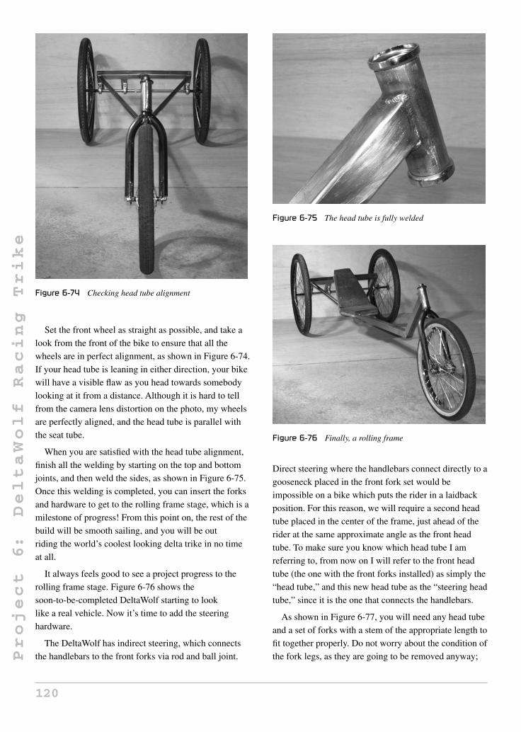
Project
6:
DeltaWolf
Racing
Trike
Figure 6-74 Checking head tube alignment
Set the front wheel as straight as possible, and take a
look from the front of the bike to ensure that all the
wheels are in perfect alignment, as shown in Figure 6-74.
If your head tube is leaning in either direction, your bike
will have a visible flaw as you head towards somebody
looking at it from a distance. Although it is hard to tell
from the camera lens distortion on the photo, my wheels
are perfectly aligned, and the head tube is parallel with
the seat tube.
When you are satisfied with the head tube alignment,
finish all the welding by starting on the top and bottom
joints, and then weld the sides, as shown in Figure 6-75.
Once this welding is completed, you can insert the forks
and hardware to get to the rolling frame stage, which is a
milestone of progress! From this point on, the rest of the
build will be smooth sailing, and you will be out
riding the world’s coolest looking delta trike in no time
at all.
It always feels good to see a project progress to the
rolling frame stage. Figure 6-76 shows the
soon-to-be-completed DeltaWolf starting to look
like a real vehicle. Now it’s time to add the steering
hardware.
The DeltaWolf has indirect steering, which connects
the handlebars to the front forks via rod and ball joint.
Figure 6-75 The head tube is fully welded
Figure 6-76 Finally, a rolling frame
Direct steering where the handlebars connect directly to a
gooseneck placed in the front fork set would be
impossible on a bike which puts the rider in a laidback
position. For this reason, we will require a second head
tube placed in the center of the frame, just ahead of the
rider at the same approximate angle as the front head
tube. To make sure you know which head tube I am
referring to, from now on I will refer to the front head
tube (the one with the front forks installed) as simply the
“head tube,” and this new head tube as the “steering head
tube,” since it is the one that connects the handlebars.
As shown in Figure 6-77, you will need any head tube
and a set of forks with a stem of the appropriate length to
fit together properly. Do not worry about the condition of
the fork legs, as they are going to be removed anyway;
120

Project
6:
DeltaWolf
Racing
Trike
Figure 6-77 Parts needed for the steering hardware
Figure 6-78 Remove the fork legs and grind the area
just make sure that if there is damage, it has not been
done to the stem as well. One thing to note: you want to
make sure the bearing races, head tube cups and bearings
do work together properly, as there are several sizes used.
Throw all the hardware together as a test—the fork stem
should turn with almost no friction, even when all of the
hardware is screwed on tight.
Start by cutting the fork legs away from the stem, and
then grind off any excess material from both the fork
crown and the head tube. What you should be left with
will look like what I have shown in Figure 6-78. Before
cutting the fork legs, remove the bearing race from the
fork stem by tapping it off using a chipping hammer or
chisel—this will ensure that it is not damaged by the
grinder wheel when cutting the legs. It should be
reinstalled once the fork stem is cut and ground clean.
Draw a line around the base of the stem, as shown in
Figure 6-78, leaving about half an inch of material just
below the top ridge where the bearing race was located.
This will remove some of the heavy tubing that was only
needed when the fork legs were connecting and taking
the weight of the rider. In this steering setup, there will
be very little stress on any of the steering parts.
The large beefy chunk of fork crown material is really
not necessary in our steering mechanism, since it will no
longer be used to support the front end of a bicycle, only
a small control arm, so it can be removed by cutting
along the line you drew earlier. After you have cut the
thick stub from the fork crown, a weld must be made all
Figure 6-79 Cut and secure the crown together by welding
the way around the underside, as shown in Figure 6-79.
If you look closely at the area that you have just cut, you
will notice that it is actually made up of two tubes that fit
together, not a single beefy tube. The part you are
throwing away would have a welded area just like the
one you are about to make in order to ensure the two
parts do not fall apart. This weld is very important, and if
it is not done, your steering could completely fail, since
the control arm is only going to be welded to the outer
tube that is fit around the fork stem.
The DeltaWolf steering system will connect the front
forks to the handlebars using a pair of control arms and
two ball joints, so that the exact movements of the
underseat handle bars will be transferred to the front
forks, giving the feel as if you were holding on to
handlebars directly connected to the front forks like that
of a regular bicycle. The two control arms are just pieces
of 1/8-inch thick plate or flat bar cut to the size shown in
Figure 6-80, and the ball joints are inexpensive steel
units with a 1/4-inch bolt hole. The ball joints can be
found at many hardware or fastener stores and many
automotive dealers—the exact type is not critical, and
they do not have to be heavy duty since there is almost
Figure 6-80 You will need two control arms
121

Project
6:
DeltaWolf
Racing
Trike
Figure 6-81 The two ball joints and the control arms
no stress put on them in out application. The rounded
area at the base of each control arm will form to the
crown area on your front steering system and to one of
the legs on the DeltaWolf’s front forks. Look ahead a few
steps to see how this works.
Figure 6-81 shows the two control arms after cutting,
as well as the two ball joints I found at a local hardware
store. The holes drilled in the control arms are the same
size as the ball joints. My ball joints are designed to
thread onto a bolt or rod with the appropriate threads, and
other types have the bolt already installed on the
body of the ball joint—either type will work just fine.
The threaded ball joints allow for some fine tuning of the
steering alignment, but once the rod is the correct length,
this should never be necessary, so I always weld the ball
joints directly to the rod, as you will soon see. Slight
steering adjustments can be made by simply moving the
gooseneck in the steering head tube if necessary.
Weld one of the control arms to the base of the fork
stem, as shown in Figure 6-82. Do this with the bearing
race removed from the fork stem (it is shown installed in
Figure 6-82) to avoid weld spatter or accidental contact
with the bearing race. The control arm will form a
90-degree angle with the fork stem, and should be welded
all the way around to ensure strength. After welding is
completed, tap the bearing race back onto the fork stem.
The steering head tube will be connected to the main
boom, just ahead of the seat base by a 6.5-inch length of
the same tubing that the rest of the frame is made
from—let’s call this the “steering support tube.” Cut the
angles at each end, as shown in Figure 6-83.
The cut steering support tube is shown in Figure 6-84,
ready for the steering head tube to be installed. The
38-degree angle is the end of the tube that will connect to
Figure 6-82 Weld the control arm to the fork stem
Figure 6-83 The tube that connects the steering head tube to
the main boom
Figure 6-84 The steering support tube
the main boom, and the 20-degree end will be rounded
out to cradle the steering head tube. These angles should
place the two head tubes at approximately the same
angles, as we shall soon see.
Place the steering head tube on each side of the
20-degree end and trace a line, as shown in Figure 6-85.
This area will be ground out to cradle the steering head
tube for welding by forming a good joint with little gap.
A grinder disc works great to rough out the area so you
can finish up with a hand file. If you accidentally take out
too much metal, then just repeat the process on the other
122

Project
6:
DeltaWolf
Racing
Trike
Figure 6-85 Trace out the area to be cut
Figure 6-86 Tack welding the steering head tube in position
side, so the fish-mouth cut is the same on both sides of
the tube.
When the steering head tube fits snugly in the cutout,
forming a parallel line along the tubing end and the head
tube shell, tack weld the top of the joint, as shown in
Figure 6-86. Take a look at the tubing from all angles to
ensure that there is no misalignment due to one of the
cutouts being off center. Then, tack weld the opposite
side of the joint to secure the head tube in place. If the
alignment looks good, weld the top and bottom of the
joint completely across to secure the part.
Now, weld the side of the joint until you have a good
weld all the way around the entire joint, as shown in
Figure 6-87. You must now install the bearing cups, the
bearings, and the fork assembly with the control arm into
this head tube, since it will be permanently installed in
the final design. The reason it will be permanently
installed is because there is not enough room to slide the
fork stem in or out of this head tube once the steering
support tube is welded to the main boom. This is done on
Figure 6-87 Welding completed
purpose, and is not a problem because you can still
grease the fork hardware once installed. Since these
bearings will never carry any load, the chance of ever
needing to replace them is almost zero. If you do have to
replace the bearings, only the lower one will be fixed, but
you could simply grease the lower cup and feed the balls
into place like they do on many expensive road bikes.
Making the steering support tube longer in order to have
the ability to remove the fork stem could certainly be
done, but really would be a waste of extra tubing for no
real reason, and it would place the steering rod higher up
at an angle to the frame that would not look as good as it
does this way.
The drawing in Figure 6-88 shows how the two head
tubes should be placed at the same approximate angle.
A few degrees either way is not a problem, but the closer
the head tubes are, the more “ balanced” the final trike
will look. This angle also makes forming the steering
hardware very simple to create a comfortable and well
positioned handlebar. Figure 6-88 also shows the typical
distance between the front of the steering support tube
and the seat back to be 10 inches. This distance is good
for a small to medium sized adult, whatever that means!
Really, if you consider yourself to be a “big” person, then
you may want to make more room by simply increasing
this distance. There will be no effect on the final handling
characteristics of the DeltaWolf if you play with the
10-inch distance, but you wouldn’t want to move the
handlebars too far ahead to be comfortable. If you think
Figure 6-88 The two head tubes will be at the same angle
123

Project
6:
DeltaWolf
Racing
Trike
Figure 6-89 Tack welding the steering support tube in place
you may need extra seat room, then only make a few tack
welds in the next few steps, and save the final welding
until after the handlebars are installed. As long as you
read ahead to understand the rest of the building steps,
you could easily do them in whichever order you like
from here on.
If 10 inches of seat room will be enough, or if you just
want to make your best guess, tack weld the steering
support tube in place, as shown in Figure 6-89.
The steering hardware is installed before you weld or you
will not be able to insert it later. It is actually the lower
bearing and cup that cannot be removed, but you might
as well install all of the hardware now, since you will
need it for setting up the steering in the next few steps
anyhow. The support tube is angled away from the seat,
not only for looks, but in the case of a severe front-end
collision, you will not get wedged under the hardware as
you would if it were reversed.
If you trust your seat base clearance, finish the rest of
the welding between the steering support tube and main
boom, as shown in Figure 6-90. Because I have built a
few of these types of low racers, including the original
Marauder (same steering design), I know that 10 inches
of seat clearance is enough for myself. If you aren’t sure,
then just leave the tack welding for now and continue on,
as you can finish this up after you create the handlebars
and install them for a trial fitting. You do not have to
weld the joint on the inside angle since it would be
difficult to do without making several passes. The joint is
plenty strong with the three other sides welded, so to
avoid adding too much heat into the joint which may
cause the boom to bow, just leave it.
Figure 6-90 Steering support tube completely welded
We need a bottom bracket as well as a front derailleur
tube, so to save a bit of time welding and worrying about
finding the correct tube diameter for the derailleur clamp,
I just hacked both from an old frame as one single piece.
The front derailleur will only clamp to a seat tube on a
bicycle, and I salvage all of my bottom brackets from old
bicycle frames, so this method made the most sense and
would spare some welding time. The size and condition
of the frame is not important, as long as the seat tube is
not bent out of alignment from the bottom bracket.
Figure 6-91 shows the old 24-inch MTB frame about to
be hacked. Goodbye old friend.
Before you select a frame for butchering, notice the
two very different sizes of bottom brackets and crank
styles commonly found: one-piece steel cranks with large
bottom brackets, and the three-piece cranks sets with the
smaller bottom brackets. Although both types will indeed
work, choose the three-piece smaller bottom bracket as
these are so much higher quality, and will yield a much
better selection of decent crank arms and gear ratios.
Figure 6-91 No, please don’t cut me
124

Project
6:
DeltaWolf
Racing
Trike
Figure 6-92 Cut the bottom bracket and seat tube from the
donor frame
The one-piece crank sets are very cheaply made, only
come with heavy steel arms, and the crank rings are thin
and prone to wear.
Install the front derailleur in whichever position it
used to be, so that you can make sure to cut out enough
of the seat tube in order to place the derailleur above the
crank ring. If you are not sure, then cut way more than
you need, like I did, as shown in Figure 6-92, as it can
simply be cut off later. Just to be safe, I cut 3 inches
above the derailleur because the largest crank ring on this
bike might be smaller than the one I planned to install on
the DeltaWolf.
If you are using a cut-off disc in your grinder to make
the cuts, then beware when cutting either the seat tube or
down tube, as the frame will tend to collapse on your
disc as you get through the last bit of metal, which could
cause your grinder to stall, or run out of your hand. If you
have no way to secure the frame while cutting, then leave
a sliver of metal during each cut rather than going all the
way through the tubing, and you can simply bend the
bottom bracket back and forth to release it after the cuts
are made. If using a hacksaw, don’t worry about it—just
hack!
Once you remove the bottom bracket and derailleur
tube from the donor frame, grind away excess metal and
fill in any holes left by overlapping tubing or those
drilled into the bracket shell. If you already had a bottom
bracket for use in this project, then you will need to hack
a length of seat tube from another frame and weld it in
place to get the assembly shown in Figure 6-93. Make
sure the tube forms a nice 90-degree angle with the
bottom bracket if you have to weld the parts together.
The DeltaWolf has an adjustable bottom bracket that
will allow riders of many different heights to adjust the
Figure 6-93 Bottom bracket cut and ground clean
trike to their inseam (leg length). This feature also makes
it easier to build, since you don’t have to worry about
getting the bottom bracket installed on the main boom to
within 1/4 inch of your required leg length. On some
recumbent bicycles, the seat is readjusted for leg length,
but imagine how complicated it would be to design the
DeltaWolf that way—you would have to move the
steering control arm, as well as worry about the steering
rod length. Moving the seat would really be impossible.
The bottom bracket and front derailleur tube move
together along the main boom, so you do not have to
worry about the position of the derailleur over the chain
ring. The DeltaWolf also has an extra chain pickup idler
under the seat, so large bottom bracket adjustment will
not require you to add or remove chain links. Cut two3/16-inch thick pieces of plate or sheet to make the shapes,
as shown in Figure 6-94. The round area is cut to
conform to whatever size bottom bracket you decided to
go with, and the two bolt holes will be drilled for 1/4-inch
bolts. The bolt holes are drilled at the edge of the plates
so that there is 1/8 of material between the hole and edge
of the plate. These two plates will form a “vice” that will
Figure 6-94 The sliding bottom bracket mounting plate
125

Project
6:
DeltaWolf
Racing
Trike
Figure 6-95 Bottom bracket plates ready to be ground
clamp the bottom bracket to whatever position on the
main boom you want.
Once you have the two bottom bracket mounting
plates cut, trace around the bottom bracket shell to draw
a line, as shown in Figure 6-95. The marker line should
meet the corners of the plate, in order to ensure that you
don’t cut out too much of the plate when grinding out the
rounded area. If you take too much metal away from the
plate, there will not be enough room between the bottom
bracket and the clamping bolts for the main boom. When
grinding out the traced circular area for the bottom
bracket, place both plates in the vice so they can be done
at the same time. This will ensure that both plates are
exactly the same size.
Once both bottom bracket mounting plates are ground
out to the same size, you can drill the bolt holes, as
shown in Figure 6-96. Remember that the main boom
Figure 6-96 Ground and drilled bottom bracket mounting
plates
Figure 6-97 The proper angle for the derailleur tube
tube must fit between the two bolts and the underside of
the bottom bracket, so ensure that there is slightly more
than 1.5 inches of room between the lowest part of the
ground out area and the top of the bolt holes. The
drawing in Figure 6-94 shows this. The two bolts that
will tighten the plates like a vice along the main boom
should have at least 1.5 inches of non-threaded area, as
also shown in Figure 6-96, or you will scratch the paint
off the underside of the frame when relocating the
bottom bracket.
In order to allow the front derailleur to properly move
the chain from one chain ring to the next, the angle of the
derailleur tube must be set to 67 degrees to the main
boom, as shown in Figure 6-97. It is actually the angle of
the tube in relation to the angle of the chain that really
counts, but it is easier to measure this angle from the
frame once it is known. This angle will allow the use of a
standard three-ring crank set as found on most mountain
bikes. A degree or two in either direction will not have
any impact on the derailleur operation.
In order to get the proper angle between the derailleur
tube and the main boom, as shown in Figure 6-97, a bit
of frame tubing can be clamped to the two plates
(see Figure 6-98). This will allow you to set the bottom
bracket into the correct position for tack welding, as well
as ensure that both plates are aligned with each other, so
that the bolt passes easily through both holes. I used an
adjustable square set to the required 67 degrees, in order
to set the bottom bracket and derailleur tube up for
making the two small tack welds at the top of the joint.
Besides the proper derailleur tube angle, the only other
important factor is the position of the plates on the
bottom bracket. With the piece of frame tubing as a
guide, you will automatically have the correct distance
between the plates, so the only other thing to ensure is
126

Project
6:
DeltaWolf
Racing
Trike
Figure 6-98 Using a bit of frame tubing as a welding guide
Figure 6-99 The completed adjustable bottom bracket
that there is approximately equal distance between each
plate and the edges of the bottom bracket. In other words,
the bottom bracket will be in the center of the main boom
as viewed from above.
Figure 6-99 shows the completed adjustable bottom
bracket and integrated derailleur tube. Since the
mounting plates are fairly thick, there was no need to
weld the inside of the joint, which helps to reduce
alignment problems due to welding distortion. If you did
weld the inside of the joint, the two plates would tend to
move closer together, which would make it very difficult
to slide the assembly onto the frame, or it would strip off
the paint when moved.
With the adjustable bottom bracket and derailleur tube
completed, you can mount the assembly to the main
boom and tighten the two clamping bolts. Figure 6-100
shows the completed assembly mounted securely to the
frame, just before cutting off the access tubing above the
derailleur. When you trim the excess tubing, make sure
that you have the actual chain ring you plan to use
Figure 6-100 Bottom bracket installed into the frame
installed, because there are many different diameter
chain rings available with various diameters. In
Figure 6-100, I have a 58-tooth chain ring installed,
which is slightly larger than those found on a typical
mountain bike. I installed the largest chain ring
commonly available in order to trim above the derailleur
so that I could swap them out later, yet still have the
ability to run the large chain ring if I wanted. Trim the
tubing above the derailleur so there is at least 1 inch of
material above the mounting strap.
The DeltaWolf requires a very unique, long and
straight gooseneck in order to mount the handlebars to
the steering head tube. You will not find anything like it
on a regular bicycle, so we will simply make our own by
using a steel seat post to extend a commonly available
steer bicycle gooseneck. Figure 6-101 shows the steel
gooseneck I chose to cut—an old BMX seat post—as
well as a set of steel mountain bike handlebars. Your goal
is to place the gooseneck clamp in a position that will
allow your handlebars to clear your legs and knees when
pedaling, yet keep your arms and hands in a very relaxed
and comfortable position. Any steel gooseneck that fits
into the fork stem you used to make the steering head
Figure 6-101 An old steel gooseneck and a steel seat post
127

Project
6:
DeltaWolf
Racing
Trike
Figure 6-102 Extending the gooseneck
tube will work just fine, but be aware that there are two
common sizes: BMX and mountain bike. BMX
goosenecks have slightly smaller diameter tubing, and
will create a very sloppy loose fit if placed into a
mountain bike fork stem. A mountain bike gooseneck
would not fit into a BMX fork stem. The seat post or
mountain bike handlebar tubing shown in Figure 6-101
will be used to make the actual extension between the
gooseneck stem and the clamp, so this tubing must be
made of steel.
How tall to make your gooseneck is really a factor
determined by your body size and the amount of padding
you plan to use on your final seat base. Just for the
record, the tube I used to extend the gooseneck, as shown
in Figure 6-102, is 10.5 inches long and made from an
old BMX seat post. Handlebar tubing, conduit, or any
similar strength tubing will work just fine.
Cut the clamp from the gooseneck so there will be
enough material to make a good joint between the
extending tube and the base of the gooseneck. As shown
in Figure 6-102, I cut the gooseneck an inch from the
stem and ground the area to allow an easy weld of the
two parts. The position and angle of the extending tube
should place the top of the tube (where the handlebars
will mount) directly over the end of the gooseneck tube.
This placement of the handlebars will remove a tiller
effect from the steering so that the handlebar turns
directly on its center axis.
Before you make any cuts or welds, it’s a good idea to
sit on the bike while the bottom bracket and cranks are
installed to see which handlebar position feels most
comfortable. Do this by holding whichever handlebars
you plan to use as you pedal so that you can find the
optimal position. Make sure you have your seat base set
up to the height it will be in the final design, including
any padding. When you are holding the handlebars at
what you think is the optimal position, have a helper
measure the distance from the handlebars to the
gooseneck and use that as a reference. In case you need
Figure 6-103 The handlebar clamp is in the center of the
gooseneck tube
to make a slight adjustment later, you will be able to
move the gooseneck up and down slightly just as it was
done on a regular bicycle.
As shown in Figure 6-103, the handlebar clamp is
positioned in such a way that if you drew a line
extending from the center of the gooseneck tube, it
would hit the center of the clamp; this is why the
extender tube is welded in place at a slight angle. Feel
free to use whichever gooseneck style you like to create
this extended version; as long as all the parts are made of
steel, you will be fine. In my version, I have a BMX
gooseneck stem, a seat post tube as the extension, and a
mountain bike handlebar clamp at the top. I needed the
BMX gooseneck stem, since I made my steering system
from a kids’ BMX bicycle, but wanted the standard
mountain bike clamp so I could use road bike handlebars.
Handlebar size and shape is totally up to you, but the
ones I decided to use, shown in Figure 6-104, are really
comfortable, and allow plenty of room to mount all the
shifting and brake hardware. These “granny” style
handlebars are common on cruiser-style bikes, and are
often found on those older three-speed, 1970s ladies’
bikes that often hide out at the local dump or scrap metal
pile. The curved handlebars seem to make extra room for
Figure 6-104 Handlebars installed
128
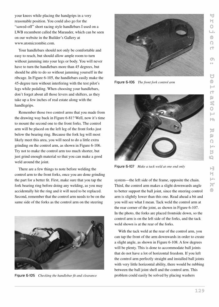
Project
6:
DeltaWolf
Racing
Trike
your knees while placing the handgrips in a very
reasonable position. You could also go for the
“sawed-off” short racing style handlebars I used on a
LWB recumbent called the Marauder, which can be seen
on our website in the Builder’s Gallery at
www.atomiczombie.com.
Your handlebars should not only be comfortable and
easy to reach, but should allow ample room to turn
without jamming into your legs or body. You will never
have to turn the handlebars more than 45 degrees, but
should be able to do so without jamming yourself in the
ribcage. In Figure 6-105, the handlebars easily make the
45-degree turn without interfering with the test pilot’s
legs while pedaling. When choosing your handlebars,
don’t forget about all those levers and shifters, as they
take up a few inches of real estate along with the
handlegrips.
Remember those two control arms that you made from
the drawing way back in Figure 6-81? Well, now it’s time
to mount the second one to the front forks. The control
arm will be placed on the left leg of the front forks just
below the bearing ring. Because the fork leg will most
likely meet this area, you will need to do a little extra
grinding on the control arm, as shown in Figure 6-106.
Try not to make the control arm too much shorter, but
just grind enough material so that you can make a good
weld around the joint.
There are a few things to note before welding the
control arm to the front forks, once you are done grinding
the part for a better fit. First, make sure that you tap the
fork bearing ring before doing any welding, as you may
accidentally hit the ring and it will need to be replaced.
Second, remember that the control arm needs to be on the
same side of the forks as the control arm on the steering
Figure 6-105 Checking the handlebar fit and clearance
Figure 6-106 The front fork control arm
Figure 6-107 Make a tack weld at one end only
system—the left side of the frame, opposite the chain.
Third, the control arm makes a slight downwards angle
to better support the ball joint, since the steering control
arm is slightly lower than this one. Read ahead a bit and
you will see what I mean. Tack weld the control arm at
the rear corner of the joint, as shown in Figure 6-107.
In the photo, the forks are placed frontside down, so the
control arm is on the left side of the forks, and the tack
weld shown is at the rear of the forks.
With the tack weld at the rear of the control arm, you
can tap the front of the arm downwards in order to create
a slight angle, as shown in Figure 6-108. A few degrees
will be plenty. This is done to accommodate ball joints
that do not have a lot of horizontal freedom. If you left
the control arm perfectly straight and installed ball joints
with very little horizontal ability, there would be rubbing
between the ball joint shell and the control arm. This
problem could easily be solved by placing washers
129

Project
6:
DeltaWolf
Racing
Trike
Figure 6-108 The control arm is at a slight angle
between the control arm and the ball joint, but this
solution is much tidier. In Figure 6-108, you are looking
at the left side of the forks, and I have reinstalled the
bearing ring by tapping it back into place. If you
accidentally welded on the bearing ring area, then
carefully grind or file it clean so the ring can be installed.
There is not a lot of room on the top side of the control
arm for a heavy weld, so make the underside weld as
solid as you can. You don’t want your control arm to fall
off while you are riding. Sure, the DeltaWolf rides
perfectly hands free, but a steering failure is no way to
test that point! Figure 6-109 shows the completely
welded front fork control arm—note the ample weld
metal on the underside of the joint.
The two ball joints will be used to connect the two
control arms together via connecting rod, as shown in
Figure 6-110, along with a light-gauge hollow steel tube.
This hardware can be found at your local hardware store,
and you are free to use whatever type of ball joints and
connecting rod you can find that will suit this project.
These ball joints do not need to be heavy duty like the
type you would find on snow machine or offroad vehicle
steering, since they are going to be taking a very light
Figure 6-109 Make this weld solid
Figure 6-110 Two ball joints and the connecting rod
Figure 6-111 Mounting the ball joints to the connecting rod
load. The heads on the ball joints shown in Figure 6-110
are about the size of a quarter, with a 3/8-inch bolt hole.
The connecting rod can be either a solid length of pencil
thickness rod, or some type of light-gauge hollow tubing
that feels fairly light, yet resists easy bending by hand.
The simplest and most reliable method of joining the
ball joints to the connecting rod is to directly weld them
to the ends of the rod as I have done in Figure 6-111. This
method works as long as you know the exact length to
make the connecting rod, and as long as you fully trust
your welding. To calculate how far away the bolt centers
of each ball joint should be, just place the steering
control arm at 90 degrees to the main boom, and then
place the front forks in their forward facing position. You
can then use this as a reference to make the connecting
rod the correct length. The other way to connect the ball
joints to the control rod is by welding a bolt at each end
of the rod which lets you screw the ball joints onto the
rod and set them to the correct length. Some ball joints
have bolt ends, and some have nut ends, so you will have
to work this out for whichever type you have. Also, when
using the screw-on method, make sure you include a
locking nut, so that the rod does not loosen up or come
out of alignment after time.
130

Project
6:
DeltaWolf
Racing
Trike
Figure 6-112 Steering control arm in the center position
The position of the handlebars is not important since
the gooseneck is simply inserted into the steering fork
stem and locked down. It is the control arms that must be
aligned so that they are both forming a 90-degree angle
to the frame when you are moving in the straight ahead
direction. In Figure 6-112, the steering control arm is
shown in the straight ahead position with the ball joint
and control arm installed. When completed, the ball joint
on the front fork will be installed on the top of the control
arm, and the ball joint on the steering side will be
installed on the bottom of the control arm. This
positioning helps the ball joint body clear the control
arm, and will keep the grease off your pant leg if you
happen to come into contact with the control arm.
Figure 6-113 shows the steering side of the linkage.
Notice that the ball joint is placed on the top of the
control arm. It could not be placed on the underside of
the control arm as it would come into contact with the
fork leg after a few degrees of turning. When you put the
DeltaWolf together for the final time, make sure to use
Figure 6-113 Steering linkage is now completed
decent bolts with locking nuts on both ball joints, so that
there will be no chance of bolts falling out after many
miles of vibration and use.
Your steering linkage will easily allow more rotation
than you would ever need on all but the sharpest of turns.
At 45 degrees rotation, the DeltaWolf will turn a circle
that would challenge a kid on a freestyle bike to copy. In
typical riding, you only need a few degrees of rotation,
but this steering system can really allow for some tight
turning circles. Figure 6-114 shows the steering in the
maximum left rotation, which would allow the DeltaWolf
to turn around in a circle with a diameter of about 10 feet
or so.
Figure 6-115 shows the clearance between the left
crank arm and the steering control rod, so nothing to
worry about here. As you can also see, it would not be
possible to place the control rod on the right side of the
frame since the chain ring and derailleur do not allow
clearance. The control rod is closest to the crank arm in
the straight ahead position, so the 1 inch of clearance
shown in Figure 6-115 is more than enough for any style
crank arm.
Figure 6-114 Steering at full left rotation
Figure 6-115 The control rod has plenty of room
131

Project
6:
DeltaWolf
Racing
Trike
On a very low recumbent bicycle or trike, the chain
must pass under the pilot’s seat in order to reach the rear
freehub. This is rarely a simple path from one point to the
other. Some recumbent cycles may have two, three, or
even four chain guide pulleys in order to route the chain
around all the obstacles from the front of the frame to the
rear, and each time you add another pulley, you add
friction and complexity to the design. The DeltaWolf has
only a single drive-side pulley, and an optional but highly
recommended return-side pickup idler to reduce chain
flop over uneven terrain. Drive side refers to the side of
the chain that leaves the top of the rear multispeed
freehub to enter the top of the front chain ring. This is the
only part of a bicycle chain that will ever be under any
tension, since it does all the work of transferring your
energy into the rear wheel. Return side refers to the side
of the chain that exits the bottom of the front chain ring
and enters the lower wheel of the rear derailleur. This
part of the chain will always be slack as it never has any
tension nor does it do any work.
We need to know which side of a chain is the drive
side and which is the return side, so that we can choose
the appropriate pulleys in order to route our chain under
the pilot’s seat. If you look at the two small plastic
wheels that the return chain pass through on a rear
derailleur, you will notice that they are nothing more than
soft plastic wheels running on a steel pin. This works just
fine due to the fact that the chain just lazily slips past the
wheels with almost zero force. If you tried to use those
plastic wheels on the drive side of the chain, they would
disintegrate the instant you put any real energy into the
cranks. For this reason, our drive-side chain needs a very
large, low-friction guide pulley in order to keep friction
to a minimum and not wear out after a few hard rides.
Figure 6-116 shows such a pulley. These nylon idler
pulleys are very common in fitness equipment that uses a
wire or rope. They are a perfect size to carry a bicycle
chain, have built in ball bearings, and will probably
never wear out. The one I used is 6 inches in diameter,
but any similar pulley from 3 inches and larger will work
just fine.
I strongly recommend that you use a pulley of at least
3 or more inches in diameter, and it must have a ball
bearing in order to work properly as a drive-side chain
guide. Skate blade wheels have commonly been used for
home-built chain idlers by carving out a slot for the chain
using a grinder or lathe, but this should really be avoided,
Figure 6-116 A nylon idler pulley with ball bearing
as there will indeed be a power loss due to the small
diameter of the pulley and the softness of the material.
For $10, you can get these nylon idler pulleys online or
at many fitness equipment stores, so why bother with a
workaround? Once you have your idler pulley, place it
near the end of the main boom where we left that 3-inch
bit of tubing past the seat tube. The pulleys should easily
fit in this space without rubbing on any part of the frame,
although you may need a washer or two between the
pulley’s bearing and the frame. Once you know there will
be no clearance issues between the pulley and the frame,
drill the appropriate sized hole at the end of the tube, as
shown in Figure 6-117. Even if you have plenty of
clearance, try to keep this hole near the end of the tube in
case you want to use a larger pulley later.
Once the hole is drilled for the drive-side idler pulley
bolt, place the correct bolt into the hole, and place a little
weld on the head side of the bolt and the frame to secure
it in place. This welding of the bolt is done so that you
Figure 6-117 Drill the idler pulley bolt hole
132

Project
6:
DeltaWolf
Racing
Trike
Figure 6-118 Securing the idler pulley bolt
Figure 6-119 Drive-side idler pulley installed
can place a lock nut on the bolt, without needing to crank
it so tight that you crush the walls of your tubing
together. Since the bolt can never come free, you only
need to place the lock nut on tight enough to secure the
pulley to the bolt. Don’t forget which side the bolt is
facing—the pulley is on the right side of the frame, so
Figure 6-118 shows the left side.
Install the drive-side chain guide pulley, as shown in
Figure 6-119, using a lock nut to avoid losing parts on
hostile terrain. My 6-inch diameter pulley has just
enough room to clear all the frame tubing, which is why I
left the 3-inch section of boom extending past the seat
tube. Your pulley may be quite a bit smaller, but be aware
of the energy loss placed on your transmission if you use
a pulley less than 3 inches in diameter or something
made of soft material. I have tried these, and learned that
they just don’t work very well, especially if you like to
accelerate hard.
The last step before you can test ride your trike would
be the installation of the freehub to the drive axle on the
Figure 6-120 Machined version of the freehub mounting part
left-side wheel. Figure 6-120 shows a nice, shiny
machined part that has a hole drilled in it for the 5/8 rear
axle, and a threaded outside that allows the installation of
a standard Shimano-type freehub. This is a nice, clean
method of installing the freehub to the axle, but it does
require you to visit the local machine shop with fifty
bucks in your hand, or to collect on that favor your
machinist buddy owes you. I had several of these made,
since I like to mess around with many different bike and
trike designs, and this is the perfect part for mounting
freehubs (multispeed and fixed gear) to an axle, so it was
indeed worth the cost and wait. The more parts you have
done at once, the cheaper it becomes for each one as well.
If you want to make the DeltaWolf “machine shop
free” like I promised could be done, then refer back to
Figure 6-51, and you will see that the dismembered steel
hub not only makes the two hub/axle assemblies, but it
also makes this exact part. The completed unit, shown in
Figure 6-57, is what we are after—a method of installing
a thread-on freehub to the end of the drive axle. If you do
choose to have the part machined, do not look up the
thread pitch for a standard freehub in your cycle book or
on the Internet and attempt to bring a beautiful drawing
to the machine shop—trust me on this one. Bring them
the actual freehub, or even a threaded hub, as well as the
axle or at least a part of the same rod you made the axle
from, and explain to them exactly what you want, how it
all fits together, and then leave the parts there so they can
measure them and test fit everything. You should also
print out Figure 6-120 and Figure 6-121 when you drop
off the parts. By the time they get to actually machining
the part, that drawing may tell them something different,
and you may find yourself waiting another two weeks for
the part to be fixed.
133

Project
6:
DeltaWolf
Racing
Trike
Figure 6-121 The freehub threads onto the machined part
As shown in Figure 6-121, the machined part will
thread right into the freehub with little effort, and then
slide onto the drive axle for a nice tight fit. Don’t crank
the freehub into the part just yet, or you may have a
tough time removing it—just thread it on until it stops
using little force.
With the left axle installed on the two pillow block
bearings so that the hub is resting as close to the bearing
as it can be installed, lock the little set screws that come
with the bearings to hold the axle securely in place. Now,
place your machined part or home-built part on the axle
and then lightly thread on the freehub until it stops. Slide
the freehub along the axle until the center of the freehub
is lined up with the center of the drive idler pulley, as
shown in Figure 6-122. Since the chain needs to travel
from the largest gear to the smallest, you want the
freehub to be centered with the idler pulley so the chain
can reach all the gears without making too extreme of a
bend. Bicycle chain is very flexible for this reason, but
there are limits to everything. Once the center of the
Figure 6-122 Checking the freehub to idler alignment
freehub is in alignment with the center of the idler pulley,
mark the axle so you can remove the freehub and place
the mounting part back on the axle in the correct place.
It will be welded directly to the axle.
I originally thought about adding a keyway to the axle
and the freehub mount, then installing a bolt at the end of
the axle so the part could be removed, but after realizing
the amount of effort and cost added to making the part,
I reevaluated this idea and decided against it. It’s not that
I decided to cut corners; I just realized that having the
part removable would actually accomplish nothing, and
would make the freehub less secure. With the freehub
mount welded to the axle, the two axle bearings would no
longer be easily removable, but why would I need them
to be? These 5/8 bearings would never in a million years
wear out with this kind of use, and I could still replace the
freehub if I needed to, so the keyway idea was scrapped.
Figure 6-123 shows the freehub mount welded directly
to the axle at the same position it was marked in the last
photo. Make sure that both of your bearings are installed
on the axle before you make this weld, or you will be
spending some time with your grinder! Only the end of
the axle needs to be welded, and as long as you remember
to place the welder’s ground clamp on the axle, not the
frame, you can make this weld with the axle and bearing
installed on the frame. I like to weld the entire joint while
a helper turns the wheel slowly around in a full circle, as
it makes a nice, continuous weld bead that way.
Once your freehub mounting part is securely welded to
the drive axle, cut the leftover axle off just ahead of the
weld and thread on the freehub as tight as you can by
hand. The freehub will tighten up a lot more on the first
few hard pedal strokes, so keep this in mind on your
initial test ride as it may feel like something is slipping at
first. Figure 6-124 shows the freehub mounted to the
Figure 6-123 Weld the freehub mount to the left axle
134

Project
6:
DeltaWolf
Racing
Trike
Figure 6-124 Six-speed freehub threaded in place
Figure 6-125 Joining two bicycle chains
drive axle in the optimal position for chain alignment
with the large idler pulley.
The DeltaWolf is so reclined that you are going to
need almost twice the length of bicycle chain that you
would normally require if perched precariously on top a
“wedgie” style bicycle. Shown in Figure 6-125 is a wad
of chain, consisting of two new lengths of standard
derailleur bicycle chain and an inexpensive tool that
makes joining chains so much easier than the “smack it
with a hammer and punch” system. Two chains may be a
little too long, but it’s a good start, so go ahead and join
them into one long single chain. Look out for those
brain-teasing loops!
Since there is no rear dropout, or threaded rear axle on
the DeltaWolf, we will need to get creative in order to
attach a standard bicycle derailleur to the correct position
under the multispeed freehub. The easiest method I have
Figure 6-126 A rear hub axle will make a derailleur
mounting peg
found is to simply emulate the original mounting method
using an old rear axle from a mountain bike hub or a long
bolt of similar size. Figure 6-126 shows a rear hub
removed from a dead mountain bike hub—you will also
need the two nuts and a few washers.
The plan is to cut the axle down and weld it to the rear
frame tubing so that the rear derailleur will mount to the
axle, just like it was on a regular bicycle. On a regular
bicycle, the derailleur is held in place by the ride-side
axle nut onto the outside of the right rear dropout. This
placement of the derailleur puts it in the correct position
for shifting the chain across the entire range of gears.
Since we can’t mount our derailleur in the exact center of
the freehub in the DeltaWolf, we will place it slightly
behind the freehub center, which is close enough for
proper operation. Figure 6-127 shows the axle cut down
to a length that will place the derailleur mount slightly
past the smallest freehub gear, as shown next.
Figure 6-128 shows the derailleur mounting bolt
welded to the frame at the bottom end of the tube, so that
the derailleur will be placed slightly to the right of the
smallest gear, and at the same height from the ground as
the rear axles. Before you weld the bolt in place, make
sure the chain can slip from one gear to the next without
getting wedged between the end of the bolt and the
Figure 6-127 Derailleur mounting peg
135

Project
6:
DeltaWolf
Racing
Trike
Figure 6-128 Derailleur mounted peg welding in place
gear teeth. If the chain hits the bolt, then it is too long. If
your rear derailleur is a very high quality unit, it may
have a different mounting system rather than the simple
dropout slide-in type that I have used. This will not
present a problem, as long as you make sure that the
derailleur is in a position to allow the full range of gear
changes without the chain striking the mounting bolt, or
whatever hardware you plan to use to secure the
derailleur to the frame.
Figure 6-129 shows my derailleur installed on the
mounting bolt that I made from a discarded rear bicycle
axle. You will probably need to tweak the two adjustment
screws on the derailleur to get it to travel to the far reach
of the freehub without falling off the last chain ring. Start
by loosening both adjustment screws out a few turns,
then try moving the derailleur across the freehub range as
a helper pedals the cranks. Your derailleur should be able
to reach all of the gears without falling off the largest or
Figure 6-129 Rear derailleur installed
Figure 6-130 Return chain management
the smallest ring. There is usually a large margin of
adjustment available on most derailleurs due to the
multiple sizes of freehubs available.
At this point, the transmission is completed enough to
test ride the DeltaWolf, although it would be a bit clunky
without shifter cabling and that return chain banging
around. The return chain has no tension, and is fairly
loose, creating a sagging arc from the front of the trike to
the rear due to its own weight. You will also notice that
while shifted into the larger rear chain ring, the chain
may actually rub against the large drive-side idler pulley
a bit, causing a clicking sound. A very simple and
effective return chain idler system can be built by cutting
up an old rear derailleur, as shown in Figure 6-130. If
you remove the part of the derailleur that connects the
two idler wheels to the main body, you will be left with a
small shaft that just happens to be the perfect length for
an idler mount if welded to the frame in the position
shown in Figure 6-130. There is no stress on the return
chain, so this idler system will not add much friction into
your drive system, but it will keep all chain flopping to
an absolute minimum and stop the return chain from
rubbing against the idler pulley when shifted to the larger
rear chain ring.
With the return chain pickup mounted correctly, you
will be able to lift the drive wheel and pedal the
DeltaWolf without any chain rubbing or grinding noises
throughout the entire gear range. With the little idler
wheels cleaned up and slightly oiled, the DeltaWolf
transmission will not make any more noise than that of a
regular bicycle, and it should feel just as smooth.
136

Project
6:
DeltaWolf
Racing
Trike
Figure 6-131 No more chain flop
Figure 6-132 Transmission top view
Figure 6-131 shows the completed transmission working
perfectly and silently.
Figure 6-132 shows the top view of the DeltaWolf
transmission. Notice how the return chain passes
alongside the drive chain in order to clear the large idler
pulley. It’s almost too bad that most of this clockwork
will be covered up from view by the seat.
If you are not used to such a low, laidback, recumbent
riding position, you may find yourself wanting to rest
your head using some type of headrest. Everyone I know
who has built an extreme low racer has stated that they
need a headrest on the first few rides, but later decided
that it was really not necessary, and became very
comfortable without it. I guess you have to get used to
sitting in positions that you are not accustomed to while
using muscle groups that would not normally be used on
a bicycle of this style. On my first extremely low
recumbent, The Marauder, I added a headrest that would
place a foam pad directly behind my head, but realized
that this caused two new problems; I could never use a
helmet, and the bumps from the road pounded the
headrest on the back of my head. For this reason, I
almost never used the headrest unless I was cruising
along on a perfectly fresh paved road.
On the DeltaWolf, I solved this problem by creating a
neck rest instead that would allow the use of a helmet,
and does not amplify road bumps nearly as bad as a
headrest would. A nice, fat, round pad was also used to
further pad the rider from vibration, and this did create a
decent neck rest, although I still rarely use it unless I am
on a leisurely cruise. If you choose to install the neck
rest, an old set of road bike forks cut at the legs makes
the perfect mounting system, and it looks great on the
final design. Simply hack the legs from the fork crown at
an angle of approximately 30 degrees, as shown in
Figure 6-133.
The fork legs are then welded to the rear frame tube so
they form a nice arc up to the position you want to install
the neck rest pad. There is a lot of room for
experimentation here, and you may even want to make
your neck rest adjustable, spring loaded, or completely
removable—an easy task that can be done with a handful
of scrap bicycle parts and some imagination. I went for
the fixed position headrest, as I thought the perfect
Figure 6-133 Cut the fork legs at the crown
Figure 6-134 Fork legs are welded to the frame
137

Project
6:
DeltaWolf
Racing
Trike
position for the neck rest pad would be directly above the
rear frame tube where the fork legs are welded. The
curved fork legs left plenty of room for my back so that
only the neck rest pad comes in contact with my body.
Feel free to experiment here; this is, after all, your own
personal ride.
The actual neck rest pad is a round cylinder of black
foam that came from some discarded fitness equipment I
found at the dump. I believe you would ask for “leg
extension pads” if you were looking to purchase these
things new from a fitness store. The hole through the
pad’s center is the perfect size for the little bit of seat post
tubing I cut off shown in Figure 6-135. The seat post has
washers tack welded at each end so the long bolt will fit
through it. The seat post is then slid into the foam pad so
the fork legs can be pushed through the two small holes
in the foam, in order to create a clamp that will hold the
neck rest in between the fork dropouts.
Figure 6-136 shows the neck rest pad held in place by
the bolt through both dropouts and the small bit of seat
Figure 6-135 Neck rest mounting tube
Figure 6-136 Completed neck rest
Figure 6-137 Parts for the elbow guards
post tubing. To plug the holes at each end of the foam
pad and hide the bolts, I pushed a pair of plastic pop
bottle caps that matched the color of my paint job. The
completed neck rest is comfortable, not too bad on most
roads, and allows the rider to wear a helmet.
If you couldn’t resist the urge to test drive the almost
completed DeltaWolf, then you probably realized how
much you needed the brakes and how close your elbows
are to the rear tires. On very uneven ground, or when
driving like a maniac around sharp corners, you may end
up rubbing your elbows on the rear tires, so some type of
elbow guard will be necessary. The simple elbow guard I
made from a few bits of thin scrap tubing and rod is very
minimal, but works perfectly and makes it almost
impossible to place your elbow against the tire, even if
you wanted to. As shown in Figure 6-137, two small
lengths of thin walled steel rod, about the same thickness
and diameter as bicycle seat stay tubing, was used as a
support arm to hold the two small curved pieces of steel
rod that form the actual elbow guard. The two small
curved rods are chinks of steel cut from a trashed
shopping cart, and they were bent by hammering them in
the vice to the approximate curvature of the rear wheel.
Again, this part of the DeltaWolf leaves much room for
improvisation, and as long as you find a way to keep
your elbows out of the wheels, then feel free to
experiment. You do not need a large elbow guard because
your elbows really cannot move all that much when you
are holding on to the handlebars, which is why my
minimalist approach works perfectly.
The elbow guard is placed at a horizontal orientation
towards the front of the rear wheel, as shown in
Figure 6-138, as this area is where your elbow will be at
rest. This simple elbow guard would also form a very
sturdy mounting base for a pair of fenders or some type
138
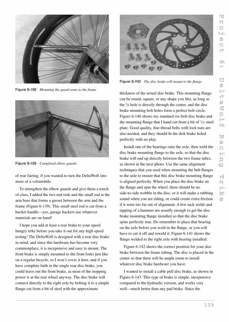
Project
6:
DeltaWolf
Racing
Trike
Figure 6-138 Mounting the guard arms to the frame
Figure 6-139 Completed elbow guards
of rear fairing, if you wanted to turn the DeltaWolf into
more of a velomobile.
To strengthen the elbow guards and give them a touch
of class, I added the two end rods and the small rod at the
arm base that forms a gusset between the arm and the
frame (Figure 6-139). This small steel rod is cut from a
bucket handle—yes, garage hackers use whatever
materials are on hand!
I hope you add at least a rear brake to your speed
hungry trike before you take it out for any high speed
testing! The DeltaWolf is designed with a rear disc brake
in mind, and since this hardware has become very
commonplace, it is inexpensive and easy to mount. The
front brake is simply mounted to the front forks just like
on a regular bicycle, so I won’t cover it here, and if you
have complete faith in the single rear disc brake, you
could leave out the front brake, as most of the stopping
power is at the rear wheel anyway. The disc brake will
connect directly to the right axle by bolting it to a simple
flange cut from a bit of steel with the approximate
Figure 6-140 The disc brake will mount to the flange
thickness of the actual disc brake. This mounting flange
can be round, square, or any shape you like, as long as
the 5/8 hole is directly through the center, and the disc
brake mounting bolt holes form a perfect bolt circle.
Figure 6-140 shows my standard six-bolt disc brake and
the mounting flange that I hand cut from a bit of 3/32 steel
plate. Good quality, fine-thread bolts with lock nuts are
also needed, and they should fit the disk brake holed
perfectly with no play.
Install one of the bearings onto the axle, then weld the
disc brake mounting flange to the axle, so that the disc
brake will end up directly between the two frame tubes,
as shown in the next photo. Use the same alignment
techniques that you used when mounting the hub flanges
to the axle to ensure that this disc brake mounting flange
is aligned perfectly. When you place the disc brake on
the flange and spin the wheel, there should be no
side-to-side wobble in the disc, or it will make a rubbing
sound when you are riding, or could create extra friction
if it were too far out of alignment. A few tack welds and
tapping of a hammer are usually enough to get the disc
brake mounting flange installed so that the disc brake
spins perfectly true. Do remember to place that bearing
on the axle before you weld in the flange, or you will
have to cut it off and reweld it. Figure 6-141 shows the
flange welded to the right axle with bearing installed.
Figure 6-142 shows the correct position for your disc
brake between the frame tubing. The disc is placed in the
center so that there will be ample room to install
whatever disc brake hardware you have.
I wanted to install a cable pull disc brake, as shown in
Figure 6-143. This type of brake is simple, inexpensive
compared to the hydraulic version, and works very
well—much better than any pad brake. Since the
139

Project
6:
DeltaWolf
Racing
Trike
Figure 6-141 Disc brake mounting flange
Figure 6-142 Disc brake mounted to the flange
Figure 6-143 Disc brake mounting hardware
mounting system needed for your disc brake could be
radically different from mine, there is no point in giving
out dimensions for the two small steel mounting tabs I
am using to secure the hardware to the frame. The goal is
Figure 6-144 Setting up the brake mount positions
to simply place the brake hardware over the disc so that
both pads grip the disc in the appropriate place. The two
small bits of steel shown in Figure 6-143 were cut from a
bit of scrap angle iron and, as you will see in the next few
steps, just about any method and placement of the disc
brake hardware can be used, as long as the pads are in the
correct position over the disc.
Most disc brakes have a generous amount of
side-to-side adjustment for aligning the pads over the
disc, so I placed the brake unit onto the disc, then tie
wrapped the brake lever into the locked position to hold
the hardware tightly on the disc. With the hardware held
in place by the brake pads, you are certain to get a good
alignment, and can simply tack weld your custom-made
mounting hardware to the frame, like I have done in
Figure 6-144. Be careful when welding near the brake
hardware, and only use small tack welds to avoid damage
to the brake hardware. I usually mask the parts with tape
as well to keep any welding spatter away from the inside
of the brake unit.
Once you tack weld the brake hardware mounting
brackets to the frame, release the brake lever to free the
pads from the disc so you can spin the wheel and check
the alignment. You may need to slide the brake hardware
a little bit either side to stop the disc from rubbing on the
pads, but if all went well, this will be easy. Some rubbing
may be normal according to your brake hardware
instructions, but there should be no extra friction when
you spin the wheel. If you are happy with the
alignment, remove the brake hardware and weld the
mounting brackets solidly to the frame, as shown in
Figure 6-145.
140

Project
6:
DeltaWolf
Racing
Trike
Figure 6-145 Disc brake mounts securely welded
Figure 6-146 The seat mounts are cut and drilled
Fastening the seat to the frame will be done using two
small brackets, as shown in Figure 6-146. Actual size and
shape is not critical, as long as you can get a few holes
for two or more woodscrews through each piece. I used a
bit of 1/16 steel plate for my seat mounting brackets,
which are about 2 inches square.
Weld the seat mounting brackets to the main boom
between the rear seat tube and the steering tube, so the
brackets will be placed directly under the center of our
seat base, as shown in Figure 6-147. A board placed
across the brackets will form a 90-degree angle with the
side of the frame, and would touch both brackets and the
top of the frame tubing at the same time since they are all
flush. The rear of the seat will be held on by drilling a
small hole through the top of the rear frame tube for a
2-inch long woodscrew, so no seat back mounting
brackets are necessary.
You just never know when you might want to pull a
trailer, or create some type of detachable tandem for the
DeltaWolf, so a little engineering ahead of time will save
you from having to repaint modified areas of the frame.
Figure 6-147 Seat mounts welded to the main boom
Figure 6-148 Trailer mounting tabs
Figure 6-148 shows one of the tabs that I welded to the
rear of the frame between the outermost bearing bolt
holes, in order to attach some type of trailer later. Since
the paint will be going on the frame very soon, this is the
time to add the little parts you may need for mounting
accessories such as lights, a horn, or whatever you may
want on your final design.
Since most of the frame was made from new tubing
with the exception of the head tubes, front forks and neck
rest, a very light sanding with a few sheets of emery cloth
was all that it took to get the metal ready for a coat of
primer (Figure 6-149). I don’t have a powder coating
station, nor do I have any place in my garage to paint, so
I simply hang my frames from an outdoor clothes line
and go to town with a few cans of spray paint. If you take
your time and follow the instructions on the can, a
remarkably good paint job can be accomplished from a
few cans of spray paint. It is true that spray paint will
scratch easier than auto point, but to look at the final
paint job, you would not be able to tell the difference.
141

Project
6:
DeltaWolf
Racing
Trike
Figure 6-149 Sanding and cleaning the frame for painting
Figure 6-150 Frame and parts painted
The DeltaWolf was built to be my main mode of
transportation, when not forced to take out the
gas-guzzler, so I painted it yellow and black in honor of
my last low racer, The Marauder, which recently retired
from many years of faithful service. Figure 6-150 shows
one of the most painful steps in building any new project:
waiting for the paint to dry! It’s too bad that this book is
in black and white, as things always look better in color.
If you decided to tackle the wheel building yourself,
then now would be a good time to tighten up all of those
spokes to true up both rear wheels. If you are new to
wheel building, then it may take you a day per wheel,
and this is OK since the paint needs a few days of curing
before you can start reassembling the DeltaWolf. As
shown in Figure 6-151, an old bit of wood will make a
perfect truing stand once you bolt the pillow block
bearings to the wood. I am using a bicycle spoke as a
guide when truing the rim, as this system works very
well. If you plan on taking your wheels to the shop to
have a bicycle wheel artist lace them up, then at least
make some kind of truing stand like I did, as they will
have no stand that can handle these alien hubless wheels.
For the axle with the disc brake flange, you will need to
cut a slot in the board.
Figure 6-151 Something to do while the paint cures
I cut my seat from a few pieces of 3/4 plywood and
some 1-inch thick, rigid, black foam. Seat construction is
totally up to you, and there are hundreds of different
materials you could use to make a great seat, depending
on your personal preference. I like a hard seat that lets
me easily shift my weight around, yet offers a little bit of
padding from the rougher terrain. This hard, black foam
needs no covering, will not soak up moisture and is very
resistant to wear. It may seem that something like this
would be uncomfortable, but to be honest, I can sit in this
seat all day long with no pain at all, but can barely take
two hours on an upright bicycle without a break. As
shown in Figure 6-152, the two seat halves are held
together by a pair of shelf brackets. The foam is glued
directly to the wood using spray adhesive, and then
trimmed by following the edge of the seat board with a
sanding disc in the grinder.
Figure 6-152 Gluing the foam to the wooden seat base
142

Project
6:
DeltaWolf
Racing
Trike
Figure 6-153 Finished seat
Figure 6-154 The cockpit
My completed seat is shown in Figure 6-153.
Rounding off the corners on the front of the seat base is a
good idea for safety reasons. The seat base is held to the
frame by the six woodscrews through the bracket on the
main boom, and the rear of the seat is fastened by a
single bolt through the frame near the top of the seat.
The DeltaWolf goes together fast once you add all the
components back onto the painted frame. Figure 6-154
shows the trike just about ready to ride as I finished
installing all the shifter and brake cabling. Cabling a bike
is a bit of a chore, but if you take your time and plan
ahead, you will get away with minimal cable that will not
rub on any of the moving parts. Notice the two yellow
pop-bottle tops placed in the head rest foam—yes, the art
of recycling!
Clean up all your transmission parts (Figure 6-155)
and use a little bit of light oil on the freehub and
Figure 6-155 Rear transmission detail
derailleur guide wheels to keep squeaking to a minimum.
Tighten all the small set screws in each pillow block
bearing so that the axles cannot slide side to side in the
bearings. Your left axle is unable to slide side-to-side
because it is held by the hub flange at one end, and the
freehub mounting hardware at the other. The right axle
could move a slight bit if the bearing set screw came
loose, which will cause your disc brake to rub on one of
the pads. The bearing set screws are usually enough to
stop this from happening, but if you want to add
redundancy, simply add a small hose clamp on the bit of
axle that sticks out from the bearing to the left of the disc
brake. Another way to secure the axle is to cut a small bit
of tubing that will slide snugly over the axle, and then
drill through both the tubing and axle to secure it in place
directly against the bearing.
Figure 6-156 shows my new aluminum three-ring
crank set with a nice large chain ring for top speed, as
well as a very small hill-climbing chain ring. I am
Figure 6-156 Good components make for a smooth ride
143

Project
6:
DeltaWolf
Racing
Trike
Figure 6-157 Ready to race, ready to cruise
normally in high gear when riding in the city, but do find
the lower gears to be a gift when hitting those seriously
long and steep hills that would normally make you get
off and walk your two wheeler up. You can move as slow
as you need to on a trike, so there is no hill that the
DeltaWolf will not climb.
Figure 6-157 shows a lean, mean trike with a speed
hungry attitude, yet it also looks well-behaved and
extremely comfortable, a fact which I can attest to. The
DeltaWolf is like a fusion between your favorite recliner
and a race car.
The first real ride with the DeltaWolf all painted up
and finely tuned was a great experience. “I will be back
in 15 minutes,” I said, but three hours later I finally found
my way home after blasting around town, passing
uprights like they were standing still, and showing off
my new ride to all those who flagged me down. What a
perfect performer! I was seriously pleased with every
aspect of the DeltaWolf’s handling from acceleration to
braking, and by the time I pried myself away from the
pilot’s seat, my legs were so worn out, I could barely
make it up the stairs. Oh, don’t get the wrong idea—the
DeltaWolf is much easier to get up to speed on,
compared with an upright bicycle, especially against the
wind—it was my extreme desire to fly past every single
bicycle I came up behind that wore me out. This thing
just wants to race! Figure 6-158 shows a bird’s eye view
of my DeltaWolf engine—aka my legs.
When you just want to lay back and take in some great
scenery without worrying about balance, or without
having a 4-inch wide seat ruin your anatomy, the
DeltaWolf fills this desire perfectly. The laidback
position makes even my office chair feel like a medieval
torture device, and I won’t even attempt to compare the
DeltaWolf seat with the killer upright bicycle seat! This
Figure 6-158 Like clockwork
Figure 6-159 Comfortable and ultra-cool looking
really is the most comfortable human-powered machine I
have ever made, and I could easily spend all day on it, as
long as my legs were up to the task. Having the ability to
take in the view while looking straight ahead in a natural
position is another serious benefit, when compared to
how you are forced to lean over the handlebars and look
up on many upright bicycles. Figure 6-159 shows a lean,
mean trike cruising along with the Sleeping Giant in the
background. The Sleeping Giant is a formation of mesas
on Sibley Peninsula, which resembles a giant lying on its
back when viewed from the north to west section of
Thunder Bay, Ontario, Canada.
In Figure 6-160, I am hitting a high speed turn and
enjoying the G-forces. Because of the extremely low
center of gravity, the DeltaWolf takes corners at speeds
that most delta-style trikes would have no chance at, no
matter how far the pilot leaned to avoid a rollover. The
full-sized, 26-inch rear wheels allow for some really
great top speed, and the special hub/axles easily handle
144

Project
6:
DeltaWolf
Racing
Trike
Figure 6-160 DeltaWolf hits the corners hard and fast
the extra demands that a non-leaning vehicle put on
them. What a fun ride!
How far can you ride before you are chased down by a
fellow cycle enthusiast to answer the same three
questions: Where did you buy that awesome trike? How
much did it cost? Can I try riding it? Hey, you can’t
blame them: look at this sweet machine! Figure 6-161
shows the DeltaWolf at rest, waiting for another ride.
So, that wraps things up! The DeltaWolf is ready to
tackle any distance you feel like riding, and it will do it
in pure style and at speeds that would make any upright
cyclist nervous. It took a bit of work to get this far, but to
be honest, the most difficult part of this project for me
was not building it; it was sitting at my computer writing
this text! Hey, I want to power this computer off and hit
that open road on the World’s Coolest Delta Trike, so I
Figure 6-161 Yes, it rides as good as it looks
Figure 6-162 DeltaWolf brings new life to the trike world
will now bid you farewell! Figure 6-162 will give you
one last look at the DeltaWolf—can you see yourself in
the pilot’s seat? Sure, you can!
145

Project
7:
Little
Warrior
Trike
Project 7: Little Warrior Trike
Since this section is dedicated to recumbent trikes, I
thought it would only be fair to build a kids’ trike so the
younger bikers can also hit the streets in style and
comfort. The Little Warrior is a nice simple trike that
does not require any machined parts or wheel building,
just a pair of kids’ bikes and a few extra bits and pieces
from your scrap pile. The Little Warrior has two front
wheels, but uses the standard front forks and head tubes,
so you do not have to worry about axle strength or
custom brake parts. You can build this little trike using
any size wheels you like, although I am not sure it would
be well suited for an adult, so wheels of 20 inches in
diameter or less would be most appropriate.
Let’s start with what you will need in order to build the
Little Warrior: two identically sized front wheels, forks,
head tubes, and a similar sized frame for the rear that
includes a crank set and rear wheel. You do not have to
match the front wheels and rear wheel, but it does make
for a better looking final product. Figure 7-1 shows the
three identical 14-inch kids’ bike frames I found at the
city dump scrap pile. These department store starter
bikes are so common at the dump and garage sales that I
probably have at least 10 more like them in my huge
scrap pile. Again, only the fronts of the bikes need to
match, as the trike is basically a bicycle with “two
heads,” as you will soon see.
Remove the front fork hardware from the two matched
frames so you can ensure that all parts are in good
Figure 7-1 Two identical fronts, and one rear
Figure 7-2 Checking the front fork hardware
working order, and that the forks are very close to the
same size and shape. If they are identical, then great, but
you could probably improvise if one of the fork stems is
a bit longer than the other. The goal is to have the front of
the trike balanced and symmetrical, so hunt around for
the best matching set of forks and front wheels that you
can scrounge. Figure 7-2 shows my two front forks,
which just happen to be identical minus color, but you
can’t see that in black and white anyhow!
You will also need a crank set, bottom bracket and all
the included hardware, as shown in Figure 7-3. Clean all
grease and rust from the bearings to ensure that there is
no damage, and replace any excessively worn parts.
Since the Little Warrior has two front ends, you will
need to cut the head tube and down tube from both
matching frames, as shown in Figure 7-4. The top tube is
146Copyright © 2008 by The McGraw-Hill Companies, Inc. Click here for terms of use.

Project
7:
Little
Warrior
Trike
Figure 7-3 Cleaning up the crank set hardware
Figure 7-4 The first cut made to both matching frames
cut right at the head tube joint, and the down tube is cut
right at the bottom bracket joint so you have the most
material to work with. When making the first cut, be
careful if using a grinder, as the frame may tend to
collapse on the disc and pull the grinder from your hands.
If you want to play it safe, cut the last little bit using a
hacksaw to release any tension in the frame. Make the
same cuts to both frames.
Figure 7-5 shows the result of butchering both frames:
a pair of matched head tubes with an included length of
down tubing attached. Again, both parts should be almost
Figure 7-5 Two identical head tubes with included down
tubes
Figure 7-6 Joining the head tubes
identical so the angles on each side of the trike are the
same when completed. You could cut one head tube to
adjust it, but that is probably more work than simply
sourcing the two identical donor frames. Grind away any
excess material at the joint of the original top tube as
well, filling the small holes in the head tube if you feel
the need.
The two head tubes will be joined together so that they
are perfectly parallel to each other, as shown in
Figure 7-6. A length of angle iron is being used as a
guide to ensure that the head tubes are perfectly aligned,
and that the joint at the ends of the down tubes fit
together with minimal gap. Don’t worry about the width
(track) of this trike; just take as little material away from
each end of the down tubes as necessary, and the trike
will be plenty wide enough for a safe ride.
Using a piece of angle iron or a flat surface as a guide,
position both head tubes so they are parallel and tack
weld your down tube joints, as shown in the top half of
Figure 7-7. With the parts tack welded, do a visual
inspection of the head tube alignment from all angles and
then complete the entire weld, as shown in the lower half
of Figure 7-7. You can also tack weld the head tubes to
your guide metal to ensure that they remain aligned as
you complete the welding.
Figure 7-7 Welding the down tube joint
147

Project
7:
Little
Warrior
Trike
Figure 7-8 Cutting the rear of the frame
Figure 7-8 shows how the rear of the frame must be
cut, removing the head tube at the end of the down tube
and the entire top tube. You can also clean up any excess
top tube material from the seat tube joint as well at this
point.
Since the end of the down tube on your rear frame must
mate with the joint between the front parts of the trike,
you will need to cut the appropriate fish mouth at the end
of this tube, as shown in Figure 7-9. This process is a
simple trial-and-error procedure, so take your time and
rough it out with a grinder disc, finishing up with a round
file. Take only as much material away as needed, or you
will shorten the wheelbase of the trike. The next photo
shows how the front and rear of the frame come together.
As you can see in Figure 7-10, the Little Warrior is
nothing more than a standard kids’ bike with two heads
instead of one. All angles and clearances should remain
the same, so you don’t have to worry about head tube
angles and bottom bracket clearances. Inflate all tires,
and prop up the parts, as shown in Figure 7-10, so you
can check the fish-mouth cut made between the rear of
the frame and the front. It is also a good idea to make the
Figure 7-9 Making the down tube fish-mouth cut
Figure 7-10 It’s like a two-headed kids’ bike
tack welds as the trike is sitting like this, to ensure that
the angles are correct.
A few tack welds made as the parts are propped up
should allow you to safely manipulate the parts if slight
adjustments are needed. Check the trike from all angles
to make sure the parts are in the correct place, making
sure the angle between the front and rear tubing is at
90 degrees. What about head tube angles? Well, if you
look directly at the side of the trike, it should look like a
regular bicycle, with the head tube angle the way it was
on the original bicycle. Of course, don’t get too fussy
about this angle; just make your best guess, or look at
any other bicycle as a guide.
Figure 7-11 Tack welding the front and rear of the trike frame
148

Project
7:
Little
Warrior
Trike
Figure 7-12 Making use of the leftover frame tubing
Once you are happy with the alignment between the
front and rear of the frame, weld the entire joint right
around the fish-mouth cut. At this stage, the frame is not
ready for any weight, so do not let the eager young pilot
jump on the frame, as it may bend the down tube where it
joins with the bottom bracket. The frame needs a few
more small tubes in order to form a triangle, the strongest
of all structural shapes. By hacking up the leftover frame
tubing, you will be able to make the two tubes needed to
form a triangle between the front and rear of the frame.
Figure 7-12 shows the seat stay tubing cut from the rear
of the two frames that were used to make the front of the
trike. Sure, you could use any scrap tubing with a
diameter of 3/4 inch, but recycling is the way to go.
There should be just enough tubing in those seat stays
if you join them end to end to make two longer tubes, as
shown in Figure 7-13. The top half of the photo shows
how the tubes were welded together, and the bottom half
shows the completed tubing after cleaning up the joints
using a flap (sanding) disc.
The two tubes made from the recycled seat stays will
create a triangle in your trike frame, as shown in
Figure 7-14, giving it tremendous strength. I will refer to
these tubes as “side rails,” since the seat will be placed
between them. Cut the side rails to whatever length you
Figure 7-13 Joining the seat stays to make two longer tubes
Figure 7-14 Adding the side rails
need to make them run from the top of each head tube to
the joint at the seat tube at the rear of the trike. Once
welded, your frame can now take its full weight safely.
Although an adjustable bottom bracket is optional, it
does make fitting your rider to the trike a heck of a lot
easier, and since kids grow like weeds, you won’t have to
cut and reweld the frame every time they grow an
extra inch. A simple adjustable bottom bracket can be
made using a section of seat tube, a seat post or similar
diameter tube, and the bottom bracket from one of the
frame leftovers. Figure 7-15 shows the parts you will
need in order to create a sliding boom adjustable bottom
bracket.
The idea is very simple. The bottom bracket will be
welded to the tube that fits into the seat tube and the
original seat post clamp will lock it in place. You will
need about 12 inches of seat tube, an 8-inch length of
seat post or some diameter tubing, and the bottom
bracket you plan to use for your trike. A fish-mouth cut
needs to be made in the end of the tube that will slide into
the seat tube, and then it is welded to the bottom bracket.
Figure 7-17 shows the completed adjustable bottom
bracket after welding the seat post tubing to the bottom
Figure 7-15 Adjustable bottom bracket parts
149

Project
7:
Little
Warrior
Trike
Figure 7-16 Making an adjustable bottom bracket
Figure 7-17 The completed adjustable bottom bracket
bracket. Now the bottom bracket can be adjusted either
way to about 6 inches, to accommodate different rides, or
small growth spurts. This assembly will now be called
the bottom bracket boom tube.
The bottom bracket boom tube will be welded to the
front of the trike frame, as shown in Figure 7-18, directly
ahead of the rear frame joint and at an angle roughly
parallel to the ground. Since chain routing is also a
consideration, it might be best to read ahead and
understand how the boom angle will affect chain routing.
The chain needs to pass under the front frame tubing
on its way to the rear wheel, so some type of guide pulley
Figure 7-18 Installing the bottom bracket boom
Figure 7-19 A chain idler pulley
will be needed to do this job. Any half V-belt idler pulley
with a center bearing will work for this purpose, as well
as a grooved-out skate blade wheel, or any other idler
you might find lying around your shop. A center bearing
is a good idea, as a simple brass bushing may introduce
extra friction into the transmission, robbing your young
pilot of valuable top speed. Figure 7-19 shows my 2-inch
diameter V-belt idler pulley and a bolt that will go
through the hole in the center ball bearing.
Figure 7-20 shows the chain idler doing its job, as well
as the general horizontal position of the bottom bracket
boom tube. As long as your chain does not rub on any
part of the frame, your idler pulley is installed properly,
although just behind the front frame tubing seems to be a
perfect place to weld the bolt. You will also need to
adjust the length of the chain to suit the best position of
the adjustable bottom bracket, using the rear dropouts to
fine tune any slack. You will be able to adjust the rear
wheel to account for about 1 inch of chain slack before
needing to add or remove a chain link.
Figure 7-20 Chain idler pulley installed
150

Project
7:
Little
Warrior
Trike
Figure 7-21 Steering control arms and bolts
The two front forks must turn together, taking into
account Ackerman steering angles, so a pair of steering
control arms is made from some 1-inch pieces of flat bar.
The steering control arms are 2 inches long with a
rounded end that will conform to the shape of the front
forks, where they are to be welded. You will also need the
appropriate sized bolts to pass though the ball joints and
the control arms. These parts are shown in Figure 7-21.
Since this trike has such a short wheelbase, and will
never see any high speeds, Ackerman steering angles are
not as much of a concern as they were on the StreetFox
described earlier in this section. Simply weld the steering
control arms on a 45-degree angle to the front forks, as
shown in Figure 7-22, and your steering will work just
fine. The angle of the steering control arms should make
them point towards the rear axle center, but 45 degrees
will be close enough for this trike.
Figure 7-23 shows the steering control arms installed,
as well as the steering rod and ball joints, which make
both front wheels turn at the same time. The ball joints
are small hardware store items which have been welded
Figure 7-22 Steering control arm welded to the fork
Figure 7-23 Adding the steering rod
directly to the half-inch rod that makes up the steering
rod. You can add a bolt to make an adjustable steering
rod like the one used on the StreetFox, but it may not be
necessary. Ensure that both front wheels are tracking
perfectly straight, and then measure the hole-to-hole
distance between the steering control arms to find the
optimal alignment position. Once the steering rod is at
the correct length, nothing will ever go out of alignment.
The pilot’s seat is a nice wide seat from an exercise
bicycle, held in place by a small bit of seat post tubing
that has been welded to the frame. Your seat should not
interfere with the steering rod, and should be placed so
that the rider’s heels do not strike the frame tubing. Some
adjustment of the bottom bracket may be needed to find
the best seating position, which is why it was a good idea
to make it adjustable. Figure 7-24 shows my seat
installed in what seems to be the optimal position for
balance and comfort.
Depending on the angle of your seat, you may want to
create the optional backrest, as shown in Figure 7-25.
Since the rear frame still has the seat tube and clamp
installed, you can simply add a bit of wood and padding
to a seat post and install it right into the frame.
Figure 7-25 also shows how the seat post was cut and
Figure 7-24 Adding the pilot’s seat
151

Project
7:
Little
Warrior
Trike
Figure 7-25 Making a backrest
Figure 7-26 Making the two handlebars
rewelded, in order to put the backrest at a more reclined
angle. Now the young pilot will not fall off the rear of the
trike if he accidentally lets go of the handlebars during
some vigorous riding.
The handlebars for this trike are made to install
directly into the front forks, adding a handle to each side
of the trike. Since the two front forks are forced to turn
together by the steering rod, the two handlebars will also
do the same. Figure 7-26 shows the bits that I will be
using to make up the two handlebar halves; two equal
length goosenecks and a mountain bike handlebar. The
two goosenecks should have equal length stems, and fit
properly in your front forks. There are two different
diameter gooseneck stems, so make sure you choose the
right ones.
The two goosenecks can be trimmed, as shown in
Figure 7-27, removing the clamps to leave only the
stems. You can also grind away any leftover material on
the stems.
The position and angle of the handlebar halves should
allow for easy reaching by your pilot, so tack weld them
in place and see if they seem comfortable and functional
before completing the welds. Figure 7-28 shows the
position and angle of the handlebars which allowed an
easy reach and full range of steering with no interference.
Figure 7-27 Trimming both goosenecks
Figure 7-28 Making the handlebar halves
The goosenecks will be adjustable left to right, so you
have the ability to set them up for best comfort. A slight
upwards angle of each handlebar seemed to make the
most sense ergonomically.
When you have the handlebar halves set up the way
your pilot likes, complete the welds, as shown in
Figure 7-29, making sure they are solid enough to take
Figure 7-29 Completed handlebar halves
152

Project
7:
Little
Warrior
Trike
Figure 7-30 Accessorize and paint
the abuse they are most likely to soon see. Both parts
should be the same size and angle.
Figure 7-30 shows the completed Little Warrior trike,
complete with luggage rack (buddy carrier) and chain
guard. The cool little trike required no machined or
custom parts, yet looks as good as any adult-sized trike.
The frame is strong enough to carry as many kids as can
pile onto it, and it may even be able to handle the abuse
of an adult rider. OK, fine, I rode it too!
It is a good idea to add the front chain guard to keep
kids’ new (and expensive) designer jeans from getting
snagged in the chain ring. The chain guard shown in
Figure 7-31 is an unmodified part from one of the donor
bikes, requiring only a small tab to be welded to the
boom in order to secure it in place.
Figure 7-31 A front chain guard is a must
Figure 7-32 Rear trike details
Figure 7-33 Riding the Little Warrior
Figure 7-32 shows the rear of the completed Little
Warrior trike, complete with buddy carrier and adjustable
back rest. Since brakes are included in the rear coaster
hub, there are absolutely no cables to worry about, and
the trike has plenty of stopping power so your crazy
young test pilots can fishtail around the corners.
Tanner puts the Little Warrior through its paces,
handling the trike with the accuracy of a highly trained
jet pilot! The completed trike (Figure 7-33) is so much
“cooler” than the run of the mill kids’ bike that every kid
on the block will want one. Do you have enough time
and spare parts to build a dozen more?
Hang on to your lug nuts! We have some wild and
crazy rides coming up in the next section.
153

This page intentionally left blank

Section 4
Wild and Crazy Wheels
155Copyright © 2008 by The McGraw-Hill Companies, Inc. Click here for terms of use.

Project
8:
SpinCycle
Stunt
Trike
Project 8: SpinCycle Stunt Trike
The SpinCycle offers a non-stop, tricked outride that can
only be described as a cross between go-cart racing and
astronaut training! Seriously, this crazy machine has to be
experienced in person to be fully appreciated. Before you
dig right into the bike pile with your hacksaw in hand, let
me tell you a little bit about the history of the SpinCycle
and some theory on its basic handling characteristics.
The original SpinCycle was contrived in 2002 by my
friend Troy Way and I in a small unheated garage during
the coldest winter months using only an AC welder,
angle grinder, and whatever scrap bicycle parts happened
to be lying in the huge scrap metal pile. I was in the
middle of writing the book, Atomic Zombie’s Bicycle
Builder’s Bonanza, and Troy had the wonderful idea for
some type of bike or trike that would send the pilot out of
control as if riding on a sheet of ice. Since I had a chapter
in the book entitled “Unclassified Rolling Objects,”
which included a bike that could fold in the middle,
allowing it to turn on a dime, I thought that this idea
would make an interesting bike for the book. Within a
few hours, we threw together the first prototype, which
was made from an old kids’ BMX bike, a broken office
chair, shopping cart wheels, and some recycled bits from
an old robot frame.
We took the crazy contraption out to the gas station
parking lot next door, and Troy sat in the nice comfy
office chair pilot’s seat and began to pedal the front
wheel drive trike in a straight line. With one quick flip of
the wrist, he was spinning out of control as if on a patch
of invisible ice. By the time he managed to get the trike
back to the place he started, he was sick from the intense
g-force and spinning action, and I was sore from all the
laughing. It was an instant success! I took the trike out
for a “spin,” and loved every second of the intense,
out-of-control ride. I went faster and faster, trying to flip
the trike, bend the frame, or warp the front wheel, but to
no avail, as the unit held together, which was surprising
considering how fast it was put together. I did manage to
flip the trike onto its side after some time, but only
because I nailed the edge of the curb, causing the unit to
stop dead and propel me into the neighbor’s snow bank.
After a few hours of great fun on the new trike, we
came up with the name SpinCycle, and I came back to
the garage to build my version for the book. The second
SpinCycle was made using the same basic principles:
a 20-inch BMX bike was cut up to make a front wheel
drive unit, which was then fastened to a basic T-shaped
frame with shopping cart caster wheels at the rear. I made
my trike as low as possible using light gauge square
tubing, and built the seat from plywood to keep weight
down to a minimum.
Once completed, we took both SpinCycles out for a
test run and found that having two of them was even
more fun than taking turns, especially since you could
have crazy games of “chicken” and races that involved
pushing your opponent’s seat to throw him wildly out of
control around corners. By the time the day was done, we
had a synchronized SpinCycle routine that would leave
onlookers in shock because of the amazing precision
which we were able to achieve—missing each other
while spinning in opposite directions by mere inches.
I guarantee that you will not be disappointed by the
incredible ride offered by this easy-to-build project, so
get that hacksaw out and start digging in the scrap pile
for the raw materials!
The first thing you will need is an old 20-inch kids’
bike (Figure 8-1) with the front end in good working
condition. We will be using the front forks, head tube,
rear wheel, pedals, chain, and handlebars; the rest will
not be needed. The front forks do not need to match the
156Copyright © 2008 by The McGraw-Hill Companies, Inc. Click here for terms of use.

Project
8:
SpinCycle
Stunt
Trike
Figure 8-1 A 20-inch kids’ bike with matching front fork
rest of the bicycle, as long as the fork stem is the correct
length for the head tube on the original frame, since it
will be used on the final design. If the forks you plan to
use are from the original frame, then this is not a
concern, but if not, it’s a good idea to ensure that the fork
stem is compatible with the head tube by placing the
bearing cups, bearings and all fork hardware in place,
just to double check. There is a 1- or 2-inch margin of
fork thread either way, but it is always best to check this
first. If the fork stem is too short, you will not be able to
install all of the fork hardware, and your forks will be
constantly coming loose. The problem is even worse if
the fork stem is too long for the head tube, as you will
not be able to screw down any of the fork hardware into
the bearing cups at all.
Forks that are bent at the stem from extensive rider use
should not be used, as this will compromise the
SpinCycle’s handling, making it impossible to drive in a
straight line, or will induce unnecessary friction in the
steering. Fork style is not really important, but if you
have a choice, use the beefiest front forks in your stock
pile, as the SpinCycle will tend to take a lot of abuse
from the “big kids.”
Now the fun part begins: hacking up the bike with
your grinder or hacksaw. First, you will need to cut the
bottom bracket and chain stays away from the main
frame, as shown in Figure 8-2. Cut as close to the rear
dropouts as you can, leaving as much length in the chain
stay tubes as possible, and it may even be a good idea to
leave a bit of the rear dropout metal as well (this can
always be ground away later). The other two cuts will be
made in the seat tube and down tube, and should be made
as close to the bottom bracket as possible to avoid
excessive grinding later. If you are using a cut-off disc in
Figure 8-2 Cut the chain stays and bottom bracket from the
frame
your grinder to make the cuts, then beware when cutting
either the seat tube or down tube, as the frame will tend
to collapse on your disc as you get through the last bit of
metal, which could cause your grinder to stall, or run out
of your hand. If you have no way to secure the frame
while cutting, then leave a sliver of metal during each cut
rather than going all the way through the tubing, and you
can simply bend the bottom bracket back and forth to
release it after all four cuts are made. If using a hacksaw,
don’t worry about it—just hack!
The only other bit of the original bicycle frame we
need is the head tube. This is cut in the same manner as
the bottom bracket, trying to get the cleanest cut possible
in order to reduce the time needed to grind away all the
excess metal, as shown in Figure 8-3. There will be no
risk of a grinder disc catching as you cut through the
tubing, since the frame is no longer a closed shape. When
you are done cutting the head tube and bottom bracket
Figure 8-3 Removing the head tube from the rest of the frame
157

Project
8:
SpinCycle
Stunt
Trike
Figure 8-4 Opening the front forks to take the rear wheel
chain stays from the frame, toss the leftovers in your junk
pile—they will probably be useful for some other bike
hacking project down the road. When you take on this
hobby, you can never have enough junk in the scrap
pile—take it from me. My garage is filled with buckets
and sorted piles of parts.
Are you feeling like a hero today? If so, then the next
job is going to test your strength, especially if the front
forks you plan to use are the beefy, thick-leg style like
I have in Figure 8-4. After building several SpinCycles,
I can assure you that not all forks are made with the same
quality or thickness of tubing, and a simple visual
inspection is no indicator of how easy it will be to spread
the fork legs apart that magical extra inch. This fork
spreading is necessary since the width of the front wheel
hub is an inch less than the width of the rear hub, as you
will see when you try to install it in the fork dropouts.
There is no magical way to do this procedure, and I have
seen all types of methods used to spread the forks, some
of which include; prying them apart with a lever made of
2 × 4s, cranking them apart with a large bolt and nut,
forcing them apart by sliding two large tubes over each
fork leg to gain mechanical advantage, and, of course,
my favorite method: grunting like a mad gorilla as you
overexert yourself! Whatever method you do use, make
sure that you don’t pry the fork legs apart too much on
the first try, or you will end up banging them back
together, which may weaken the metal. I like to pull up
on one of the legs as I stand on the other, trying to widen
them up just a little bit at a time, until I can force the rear
wheel axel into the dropouts. Each time I need a little
more stretch, I pull up on the other leg—this seems to
open both legs at an equal distance. Good luck!
So, how did the fork widening operation go? Can you
still stand up straight? You will feel it tomorrow,
Figure 8-5 Rear wheel installed in the front forks
trust me! Anyhow, with the only real manual labor out of
the way, we are free to get the rest of the SpinCycle
together; it’s all smooth sailing from here. As shown in
Figure 8-5, the rear wheel should be easy to install in the
front fork once the legs have been pulled apart a little bit.
Ensure that the wheel can be centered, and that the drive
sprocket does not rub on the fork leg or the dropout.
If the fork dropouts are installed closer to the outer
edges of the fork legs, you may need to install a few
washers between the axle bolts to stop the drive
sprocket from rubbing, but this is not going to pose a
problem later.
The heart of the SpinCycle is the front-wheel drive
system made from the original frame’s bottom bracket,
the front forks, and a small length of slightly bent tubing
or electrical conduit. I like to lay out the various parts as
I build, so I can get a visual picture of how everything
will fit together before I begin the welding process.
To create the front end, start by installing the front wheel
and inflated tire (actually a rear wheel) into the forks.
The bottom bracket that you cut from the original frame
is going to be attached to the front forks right at the
dropouts, so that the fork legs and chain stays form an
approximate 95-degree angle. This is shown in
158

Project
8:
SpinCycle
Stunt
Trike
Figure 8-6 Laying out the front end parts
Figure 8-6. Don’t be too critical of the 95-degree angle,
as it’s just a guide, so you can set it up by eye with no
protractor necessary! I chose the 95-degree angle
because this will place the cranks at a comfortable level
once the front end is installed in the main frame. If the
cranks are too low, the pedals may hit the ground in
turns, and if they are placed too high, your only view
when riding will be your new running shoes.
Once you have the front wheel installed and the
bottom bracket placed roughly in the correct position,
you can now figure out the correct length and rough
curvature for the steering boom (the bent tube that joins
the bottom bracket to the fork crown). This tube is just a
bit like bicycle type tubing or thin walled electrical
conduit (EMT) bent in the center to allow clearance for
the front wheel. Again, there is no critical measurement
or system for bending this tube. I just take a longer than
necessary bit of tubing, and then bend it over a car rim or
some other round object a little bit at a time until it looks
like it will fit. If you want to get fancy, you could make a
nice curve around the front wheel but, in reality, any
bend will do, even a cut and reweld if your tubing is too
rigid to bend easily.
Once you have bent the steering boom so that there is
no front tire rubbing, you can mark the area to be cut by
drawing a line as the tubing is placed over the bottom
bracket, as shown in Figure 8-7. Remember, the chain
stays will be approximately at a 95-degree angle to the
fork legs, and the steering boom should not rub on the
front tire. If the boom looks like it might rub on the front
tire, just bend it a little more until you reach a happy
medium. To mark the steering boom for cutting, just
draw a line at the approximate correct angle by visually
“guesstimating” it, a method employed by all good
Figure 8-7 Marking the steering boom to be cut
Figure 8-8 Parts needed for the SpinCycle drive system
garage hackers. Don’t worry if your cut leaves a little gap
after you place the parts back together; after all, that’s
what welding rod is for—filling gaps. You now have all
the parts to complete the SpinCycle’s drive system.
Figure 8-8 shows all the parts needed to create the
SpinCycle’s front end. I ground off any excess material
from the bottom bracket, head tube and front forks. It is
also a good idea to ensure that both legs of the chain
stays are of equal length before moving to the next step,
or your bottom bracket could end up off center. This is
done by standing the bottom bracket up on the chain
stays to see if it is level with the ground. Grind the end of
whichever leg is longer, if necessary, until you are
satisfied that they are of equal or close to equal length.
Even if you cut both tubes at the exact same stop from
the original frame, this does not guarantee equal length.
After all, these are “department store” bikes we are
dealing with, and exact quality is not something normally
found in this variety of bicycle.
159

Project
8:
SpinCycle
Stunt
Trike
Figure 8-9 A 95-degree angle is formed between the two
parts
As shown in Figure 8-9, the ends of the chain stays are
tack welded to the front of the fork dropouts, so that the
angle between the stays and fork legs is approximately
95 degrees. Only tack weld the lower front ends of the
stays to the dropouts, so that you can bend the two pieces
slightly in either direction to allow a good fit when you
place the steering boom tube in place. With two decent
tack welds holding the pieces together, you will be able
to bend them several inches in either direction, which
might come in handy if your angle was slightly off when
you did the welding. At this point, you will want to
examine the tack welded parts to make sure that
everything looks aligned properly. It is also a good idea
to carefully slip the front wheel in place as well, just to
ensure there is no misalignment from either chain stay
tube being too long or too short. If all goes well, the
wheel should be aligned between both the fork legs and
the chain stays. If this is not the case, just bend the parts
back and forth a few times to break the tack weld and try
again. If either chain stay needs a little grinding, then
only remove what is necessary, as you do not want to
make the tubes so short that the wheel will no longer
clear the bottom bracket. When you are happy with the
alignment, move on to the next step.
The steering boom tube will now be tack welded in
place, as shown in Figure 8-10. Simply place the boom
into position, then bend the bottom bracket in either
direction to form a tight fit between all of the parts (this
is the reason for the light tack weld earlier). The ends of
the steer boom will need a little bit of grinding in order to
conform to the curvature of the bottom bracket and fork
crown for easier welding. Just take a little bit out of the
Figure 8-10 The front end tack welded together
end of the tube with your grinder, and then do a test fit to
see if the joint is properly fit for welding. Alignment of
the steer boom for tack welding in place is no contest, as
it is already made to fit perfectly in place, and as long as
your bottom bracket and fork legs are aligned, everything
will fit nicely together.
Before you commit to welding every joint, place the
front wheel with the tire inflated into the fork dropouts
to check for alignment and clearance just in case
(see Figure 8-11). Most likely, everything will fit
Figure 8-11 Test fitting the front wheel in place to check
clearance
160

Project
8:
SpinCycle
Stunt
Trike
Figure 8-12 Alignment checks out from every possible angle
perfectly, but if this is not the case, it is not a big deal to
break a weld and make corrections at this point. Even
with this fat 20-inch tire, I have a good half-inch
clearance between the fork legs and the steering boom.
A little clearance is a good thing, as it will allow for a
slight adjustment of the wheel in the dropouts to ensure
that the chain is tight later on.
Checking alignment from every possible angle is a
good idea, since it’s easy to break a tack weld if
necessary to make corrections (see Figure 8-12). Once
you weld the front end together, you will have no chance
to repair any alignment errors later.
When you are finished test fitting the front wheel, and
certain that the front end parts are aligned properly, go
ahead and complete all of the welding, beginning with
the joints between the chain stay ends and fork dropouts.
By starting with those two welds, you will reduce the
chance of any side-to-side distortion due to heat while
you are welding the steering boom tube in place. In
Figure 8-13, all of the welds are completed and ground
for appearance. Before welding the joint at the steer
boom and fork crown, you should remove the forks
bearing ring by tapping it off with a chisel or welding
hammer. The ring is only held on by friction, and should
Figure 8-13 The fully welded and completed front end
come off easily. Removing the ring allows the weld to be
completed without damage to the ring itself, which must
be perfectly smooth and free of weld spatter in order to
function. Be careful not to weld the area that seats the
ring as well, or you will find yourself grinding the area in
order to bang the ring back in place later.
With the front end completed, it’s now time to begin
building the SpinCycle’s main frame. We will be starting
from the back of the bike by creating the T-bar that will
hold both caster wheels in place, preventing the trike
from rolling over. In my original design, I bolted the
caster wheels directly to the T-bar by drilling a hole in
the underside of the square tubing and simply bolting
each caster wheel in place. This method does indeed
work, but only if the square tubing used to make the
frame has at least a 1/8 wall thickness. After building a
few SpinCycles, I found 1/8 wall tubing to be much too
heavy, and went to 1/16 tubing or as close to .0625-inch
wall thickness as possible to minimize weight and allow
for better acceleration. The 1/16 wall tubing made a
frame equally as rigid as the thicker tubing, but would
not allow the caster bolts to be placed directly into the
tubing ends.
The 1/16 wall tube would tend to bend if the caster
wheels struck a curb during a spinout, and although this
161

Project
8:
SpinCycle
Stunt
Trike
Figure 8-14 Two pieces of angle iron will secure the rear
caster wheels
practice should be avoided, I didn’t want to release plans
for a bike that could be so easily damaged. Another
reason for not placing the bolts inside the T-bar was
because this left the sharp open end of the tubing
exposed, which could become a hazard under certain
conditions. The new method of mounting the rear casters
involves cutting two small pieces of 1/8-inch or
3/16-inch angle iron (Figure 8-14) to 1.5 inches in
length, so that a solid wheel mount is formed which will
also cover the exposed end of the tubing.
If you do not have the 3-inch length of angle iron
needed to form the two caster mounts, just visit any
machine shop or welding house, and they will gladly find
you a bit of scrap from the pile; this stuff is extremely
common. The thickness of the angle iron is not critical,
but it should not be less than 1/8 of an inch, or strength
may be an issue. As you can see in Figure 8-15, the two
Figure 8-15 Rear caster mounts are cut, drilled, and rounded
for safety
pieces are cut at 1.5 inches and drilled so that they form a
sturdy place to mount the caster wheel bolts, as well as
plugs to cap the open end of the rear T-bar. The side of
the angle iron with the hole drilled should also be
rounded smooth, so that your SpinCycle is not a
dangerous ankle-slicing death trap. Trust me; you don’t
want to be playing chicken with your buddy on his
SpinCycle if the ends of the frame tubes are sharp.
Remember the movie “Gladiator”? Yikes!
The key to the SpinCycle’s wild and crazy
maneuverability is the fact that all three wheels steer!
When you turn the front wheel, the bike will move in that
direction as expected, but if you lean into the turn, or
exaggerate it, the rear casters will also begin to steer due
to the momentum of the rear end. Remember what that
Newton dude taught us: “every object in a state of
uniform motion tends to remain in that state of motion
unless an external force is applied to it.” In other words,
once you get that rear end swinging, you better just hang
on and enjoy the ride!
I’m sure you recognize the wheels shown in
Figure 8-16, and know exactly where to get them: from
discarded shopping carts, of course. It’s amazing how
many shopping carts with perfectly new caster wheels
end up at the city landfill or scrapyards, especially right
after the snow clears. It’s the front wheels you want from
the shopping cart, and they can be removed simply by
taking out the bolt that holds them in place. Try to find an
identical pair of wheels so that the trike sits level.
The rear T-bar is made from a 2-foot long piece of
1.5-inch, 1/16 walled square steel tubing. You could use
heavier gauge tube, but it is not necessary, and will only
add weight to the trike. If you have no luck in finding the
correct square tubing, you could always use the same
Figure 8-16 Attention shoppers!
162

Project
8:
SpinCycle
Stunt
Trike
Figure 8-17 Mounting the caster wheels to the rear T-bar
length of 1.5-inch thin walled electrical conduit (EMT),
as it has approximately the same wall thickness and
strength as the square tubing. As shown in Figure 8-17,
the two pieces of angle iron are tack welded to the ends
of the T-bar, so that the caster wheels are both aligned at
the same exact angle. If one of the caster wheels is
misaligned, you may find your SpinCycle trying to turn
in one direction like a badly aligned 1973 station wagon,
or one of the casters may develop a seriously annoying
flutter when you reach a decent speed. A nice trick I use
to get the two pieces of angle iron aligned is to place the
works on a level hard surface as I tack weld; this ensures
perfect alignment every time.
It’s always a good idea to install the part and check
alignment before cranking up that welder (Figure 8-18).
Bolt down both caster wheels and take a look at the T-bar
from every direction until you are satisfied that both
caster wheels are aligned at the same angle. If you
leveled the T-bar and angle iron bits on a hard surface
while tack welding, then you should have no problems at
Figure 8-18 Check caster alignment before finalizing the
welds
Figure 8-19 The completed T-bar fully welded and ground
smooth
all. You may also notice that there is a slight keyway
thing on the caster wheel bolt, just below the threaded
part. Do not bother trying to keyway the hole you drilled
in the angle iron, and certainly do not make the hole
bigger to accommodate this. Simply grind or file it off, as
it has no purpose except to stop the wheel from turning
as you install the nuts. All you need to do is hold onto the
wheel as you tighten the nuts.
Once the rear casters are aligned, finish the welding of
the angle iron wheel mounts to the rear T-bar and then
grind away any sharp edges, as shown in Figure 8-19.
Remember, when you pedal like mad and start pulling
multiple 360s, the rear T-bar is going to be flying around
like a lawnmower blade, so you certainly do not want
any sharp edges. Really, this thing isn’t anything like a
plastic kids’ toy, and it can move as fast as the bike you
took apart to build it. I routinely pull five or more 360s in
a row at a speed of at least 15 miles per hour!
The main frame is made from the same 1.5-inch, 1/16
walled square tubing as the rear T-bar. Again, if you have
no luck finding decent square tubing, you could use the
same length of 1.5-inch thin walled electrical conduit
(EMT), as it has approximately the same wall thickness
and strength but will be a little more difficult to cut at the
proper angles. Have a look at Figure 8-20 to get a general
idea of what you will need to cut in order to create the
main frame. I say “general idea” because these angles
and lengths are not critical at all, and you may want to
experiment or alter the frame to suit your own needs. You
could certainly make your SpinCycle using the same
measurements and angles as mine, but before you start
163

Project
8:
SpinCycle
Stunt
Trike
Figure 8-20 Laying out the parts that make up the main
frame
cutting, read ahead and I will show you how and why I
chose those angles and dimensions. Essentially, I will be
working backwards through the process of building the
main frame, starting with the mounting of the head tube.
Since the SpinCycle has little in common with the
standard diamond frame bicycle, I am going to rename
the three tubes that make up the frame, so you know
which part I am referring to. Starting from the left in
Figure 8-20, we have the rear tube (this is your backrest),
the base tube (the bottom of the frame), and finally the
front tube (joins the head tube to the base tube). From
here on, I will be referring to the frame bits by those
names. Begin by cutting a length of tube for the front
tube. Cut this tube to a length of at least 20 inches, as this
way it will not end up too short after you cut the ends to
the proper angles and grind out the top for the head tube.
This tube is like the “kingpin” for the entire frame, and
will dictate how the rest of the tubes are cut and at what
angles.
The reason the front tube is not cut to an exact length
at this time is because it is really dependent on the front
wheel, fork angle, and dropout position on the fork legs.
The goal is to have the front tube pass by the back of the
wheel with minimal clearance of an inch or less.
By keeping the front tube as close to the front wheel as
possible, it will allow riders with short legs to pilot the
SpinCycle. Typically, the SpinCycle made with a
20-inch front wheel will fit riders ranging in height
from 5'-5" to 6'-6" with an optimal height of 5'-9".
Short riders might have to stretch a little, and tall riders
may feel a bit cramped, but hey, it’s not a touring bike,
and either way the pilot is going to be having one
heck of a good time. Again, it’s a good idea to scan ahead
a bit here before you start cutting, just so you understand
why I am not dictating exact measurements for this part
of the project. In Figure 8-21, I cut the top of the front
tube to the correct angle for my front end and ground the
joint to mate perfectly with the head tube. I will end up
with a 1-inch clearance between my front tire and the
front tube.
As you can see in Figure 8-22, the exact length of the
main tube is dependent on the geometry of the front end,
and your setup may be a little different due to the angle
Figure 8-21 Cutting the front tube to mate with the head tube
Figure 8-22 Front tube length is based on ground clearance
and fork angle
164

Project
8:
SpinCycle
Stunt
Trike
of the fork stem and placement of the fork dropouts. The
goal is to allow the front tube to pass down past the front
tire, leaving no more than an inch clearance. You should
have your front tire fully inflated while you lay the parts
down for marking the front tube to be cut. When the top
of your front tube is cut to fit the head tube, as shown
earlier in Figure 8-21, it can be tack welded in place, as
shown in Figure 8-22, and you will now be able to
calculate the correct angle and length of the tube, which
is, again, based on whatever length is going to fit your
SpinCycle best.
Take another look at Figure 8-22, and you will see that
I have placed the front end (with front tube tack welded
in place) at the same angle it would be if the entire trike
were completed, which allowed me to cut the lower end
of the front tube at the correct length and angle. The
correct angle of the front end is derived by finding a good
balance between pedal to ground clearance, head tube
angle, and underseat clearance. Simply place the front
end with front tube attached on the ground and draw an
imaginary line for the ground. Your head tube angle
should end up somewhere between 35 and 45 degrees to
the ground, while allowing a clearance of about 6 inches
between the lowest point of the crank arm and ground.
You will have to measure the length of your crank arm or
install it temporarily into the bottom bracket to get this
distance. Again, none of this is too critical, and if your
front end looks like what I have in Figure 8-22, then you
will be OK.
When you are happy with the position and angle of the
front end, you can then place the base tube over the
bottom of the front tube to get the proper cut angle and
position to join the two. Just make sure that there is
approximately 5 to 6 inches of clearance between the
bottom of the base tube and your imaginary ground line.
Figure 8-23 shows the completed welding between
the head tube and front tube. It was easier to clean up
this weld before any other frame tubing was welded, so
the part could be placed at any position in my
workbench vice.
Once you get the correct length and angle to cut and
mate the front tube to the base tube, the rest of the frame
is easy to finish. The rear tube (backrest) is simply a
length of tubing approximately the same length as the
base tube (about 12 inches) that forms a 130 to
135-degree reclined angle for your seat. In recumbent
bicycle terms, your seat is at a 45-degree angle (the angle
Figure 8-23 Welded and ground joint between front tube and
head tube
on the bottom side of the 135-degree angle). I chose this
angle because it seemed to place the rider’s weight in the
perfect place for balance between front wheel traction
and 360 ability. If too much weight ends up over the
T-bar, you will have a tough time getting grip on the road,
and if too much weight is at the front of the trike, you
will never be able to pull the almighty 360 maneuver. So,
if you have been reading ahead to understand the frame
geometry, that was how I derived my original angles back
in Figure 8-20. Your frame will look similar to the one in
Figure 8-24, but will most likely have slightly different
angles and lengths, and this is OK as long as your pedals
are not going to hit the ground, and your butt will fit
properly in the frame. If you are a “really big kid,” then
just add an inch or two to the base tube length, that’s all.
Figure 8-24 The main frame is completed
165

Project
8:
SpinCycle
Stunt
Trike
The one last step to making the frame involves getting
the proper placement of the T-bar in relation to the base
frame. Again, there is no magic formula here, as it is all
done based on what you have made so far and how you
want your SpinCycle to behave. Before I explain the
T-bar angle, install your head tube bearings and rings into
the base frame and place the front end into the frame
with tire fully inflated. We are going by ground
clearance, so you will want the two parts set up just as
they will be in the final design. You will now place the
base tube into a vice or place a few blocks under it so that
it is parallel to the ground, having the same clearance you
planned for a few steps earlier. If your front end is
flopping around like a fish in a boat, then just remove the
top bearing and clamp the fork bolt down tight to add
friction—this will not affect the position of the base
frame. Once your SpinCycle is set up like the one in
Figure 8-25, you can now place the T-bar up against the
back of the rear tube with a pair of blocks behind the
caster wheels to hold them in place.
The angle of the T-bar is very slight (between 3 and
5 degrees), and this is the main factor determining how
your SpinCycle will behave. If you want to start spinning
very easily, use 3 degrees or less, and if you want to get
up to a higher speed before spinning, keep the angle at
5 degrees or slightly more. I always use approximately
4 degrees on my T-bar, as this allows a decent amount of
control, yet gives me non-stop 360s on command. The
T-bar angle is really setting the angle of the caster wheel
bolts. The greater the angle, the more the casters will
Figure 8-25 Determining the proper T-bar to frame
placement
Figure 8-26 Marking the cutout for the rear tube and T-bar
joint
resist spinning around, thus keeping your SpinCycle
traveling in a straight line until Newton’s law takes over.
I know, 4 degrees is pretty slight, and it would be
difficult to get that right on my simply eyeing it up and
marking it, like I did in Figure 8-26 but, in reality, your
best guess will do just fine, as there is plenty of room for
adjustment during the welding process, as you will
soon see. Just place your T-bar against the rear tube at
what looks like a 3 to 5-degree angle (clockwise rotation
as looking at Figure 8-26), and make your mark on the
rear tube. The cutout for the T-bar will be approximately
an inch deep into the rear tube, or about halfway in.
Trace your marked area to both sides of the rear tube,
and then cut the section out using a hacksaw or grinder
disc (see Figure 8-27). Perfection is not necessary here,
and if the hole is a little bigger than the T-bar tube, this
will be fine, since you are going to be tinkering with the
Figure 8-27 Cut out your marker area
166

Project
8:
SpinCycle
Stunt
Trike
Figure 8-28 Tack welded T-bar ready for adjustment
angle to get it correct anyhow. Once the cutout mates
with the T-bar tube, move ahead.
Do your best to tack weld the T-bar into the cutout so
that it ends up as close to your desired angle as possible,
as well as creating a 90-degree angle with the frame. The
tack weld should only be done along the top rear end of
the joint, as shown in Figure 8-28. This will allow for
some fine tuning with your good old hammer to get that
magical 4 to 5-degree angle. The tack weld will be strong
enough to place the bike on the ground, but certainly not
strong enough to carry any weight, so avoid the extreme
urge to get into that pilot’s seat—that time is just around
the corner, promise! For alignment purposes, place both
caster wheels facing the rear (this is their natural
orientation).
To get the T-bar all lined up for welding, first make
sure you have a good 90-degree angle with the frame, as
shown in Figure 8-29, so you will not be leaning in the
bike while traveling in a straight line. Check from the top
of the bike and the rear while whacking the T-bar into
position with your mallet. Do not worry about the 4 to
5-degree T-bar angle until your frame is sitting up
straight. Remember to do this with the casters in their
neutral position facing the rear. When you are satisfied
with the frame-to-T-bar relationship, you can then adjust
the T-bar angle by placing an adjustable angle square on
the ground and against the rear of the T-bar. If you have a
good eye and a lot of luck, that magical 4–5 degrees may
be already there, but if not, just clamp onto the T-bar
center with a pair of vice grips and force the tack weld to
bend a bit until the angle is what you want. Make sure to
recheck the frame alignment as well if a lot of bending
Figure 8-29 Make sure you have a 90-degree angle with the
main frame
was necessary. Don’t rush this step. Bend and check all
angles until you are sure nothing is misaligned before
any more welding is done. Once you are certain all looks
well, tack weld the underside of the T-bar and rear tube,
then repeat the checking process.
Continue welding in small steps, filling in the joint at
the rear of the T-bar and under the frame first, making
sure your angles stay the same along the way. Save the
side welds for last, as you will still have the ability to flex
the two parts into correct alignment with only the back
and underside of the joints welded. When welding the
sides, again do it in small steps, alternating sides often, as
there will be a tendency for the T-bar to become out of
alignment from heat distortion. Take your time on this
part of the build, and don’t be afraid to hack up a bed
weld and start over, as it’s worth it in the end. After this,
the rest of the build is easy, and can be done with one
hand in your pocket and blindfolded. OK, it’s not that
easy, but you have just finished all of the tough stuff.
Figure 8-30 shows the completed weld.
It’s time to get the pilot’s seat mounts in place, and
you can do this from bits of flat bar or the same angle
iron that was used to make the caster wheel mounts. This
metal does not need to be any heavier than the frame wall
thickness, as its only duty is to bolt down the plywood
seat and cap the sharp open end of the rear tube.
Figure 8-31 shows the 1.5-inch bit of angle iron cut,
rounded, and drilled for a bolt or large woodscrew.
167

Project
8:
SpinCycle
Stunt
Trike
Figure 8-30 Welding should be done in small steps, checking
along the way
Figure 8-31 The top seat mount made of angle iron
There is nothing special about welding the seat mounts
in place. Just weld around the edges, and then clean up
the rough spots with your grinder (Figure 8-32). You will
now need some 3/4-inch plywood to create the seat.
You can make your seat out of whatever material you
like, but the old-fashioned 3/4 plywood with foam glued
to the top method seems to be the easiest. Any width
between 10 and 12 inches makes a fine seat, and the
height will be dictated by the length of the rear and base
tubing. I like rounding the top of the backrest part of the
seat to avoid sharp edges and give it a nice look. Rigid
foam can be glued directly to the wood, and may be fine
without any covering at all. The six small plates shown in
Figure 8-33 will be used for mounting the bottom of the
backrest and the seat base to the frame. They are just
pieces of thin flat bar or plate with holes drilled for a
woodscrew, nothing critical.
Weld the other seat mounting plates to the frame, as
shown in Figure 8-34. Yes, you could just drill holes right
Figure 8-32 The rear seat mount also caps the open end of
the tube
Figure 8-33 Plywood and foam used to create the pilot’s seat
Figure 8-34 The other seat mounts are welded to the frame
168

Project
8:
SpinCycle
Stunt
Trike
Figure 8-35 Underside shot of the seat-mounting process
into the base frame tubing and use bolts or long
woodscrews into the plywood, but that would be an ugly
shortcut, and not as strong as this simple method. The
small plates are welded in place so that they are flush with
the top of the frame where the plywood will be fastened.
A few good-sized woodscrews cranked into the
plywood will be plenty of fastening strength for the two
seat boards (see Figure 8-35). If the screws are a bit too
long, just grind off the tips on the pilot’s side of the wood
with your grinder. You will also notice that I rounded the
edges of the front of the seat board using the grinder disc,
just to make sure that there will be no dangerous edges
on the trike.
With your seat fastened to the frame, you can now
install all the drive components to get your SpinCycle in
a test-drive-ready state, as shown in Figure 8-36. You
will certainly need to cut and join the drive chain to the
correct length, and if all goes well, it should be nice and
tight once you get it installed on both chain rings. There
is not a lot of room for chain adjustment here, since we
are not using rear dropouts to hold the front wheel, so
you may need to do a small amount of filing or light
grinding on the edges of the dropouts to accommodate
your drive chain. If your chain is slightly too long,
remove as many links as you can before the chain
becomes too short, and then you may need to file the
dropouts on the edge facing the cranks. Your goal should
be a nice, tight chain, not one that is so loose that it flops
Figure 8-36 Almost ready for flight
against the drive tire. A $10 chain link tool is really
handy for this part of the build, and will save you a lot of
time if you need to experiment with the chain links.
Smacking the links with a punch and hammer is a wasted
effort, and the cause of much unwarranted frustration.
The next step is optional, but highly recommended, as
it will spare your pants from getting worn out as the front
wheel rubs during extreme cornering. The original
SpinCycles did not have fenders, but after many rides,
I noticed that the slight rubbing of the front wheel against
my legs during tight corners was wearing a hole in the
material! On a few rides, this was not a big deal, but after
a few hours, you will wish you had a fender installed.
Can you just throw any old fender on the bike to fix the
rubbing problem? Nope, it will not be strong enough, and
will make your SpinCycle sound like a power saw when
it rubs against the tire. The fender is made from 16 or
20 gauge sheet metal and, when welded directly to the
fork legs, will become a very strong barrier between your
legs and the hungry tire. Again, you could skip this point,
but it is recommended, especially for shorter riders who
are stretching to reach the pedals. Just take the SpinCycle
out for a test ride like it is, and you will see what I mean.
The fender plates are shown in Figure 8-37. Just use a
few pieces cut to conform to the curvature of the inflated
tire, so when the fender is installed, it reaches to the base
of the seat in order to keep pants and tire separated. The
center part of the fender is just bent by hand to form
the curve.
The fender is welded together at the corners, as shown
in Figure 8-38. To keep it straight, place a few tack welds
at first, so you can bend it into alignment by hand. Once
aligned, weld the entire length of the joint edges on the
169

Project
8:
SpinCycle
Stunt
Trike
Figure 8-37 Making the fender to stop wheel rubbing
Figure 8-38 Welding the fender parts together
outside of the fender. Welding on the inside is not
necessary, and will only cause distortion.
Once fully welded, a sanding disc does wonders to
make the fender edges clean and smooth, as shown in
Figure 8-39. There is no point in making a clothing guard
with sharp edges! Once welded, you will be amazed at
how strong the fender becomes.
Test fit the fender on the fork legs, and grind the shape
of the ends, if necessary. Once installed, it should allow a
little clearance for the tire, but provide a tight fit, as
shown in Figure 8-40. Only a few beads of weld may be
needed to hold the fender in place, but I like to weld the
entire joint, then grind it clean just for a nicer,
professional look. I also like to tack weld the fender in
place while the inflated tire is installed to ensure there is
no rubbing. This is generally not a problem if you keep
Figure 8-39 A little grinder magic does wonders
Figure 8-40 Optional but highly recommended fender
installed
the tack welds to a minimum. If you are worried about
melting your tire, just throw a scrap wheel or tire on for
this procedure.
With your fender installed and drive hardware
mounted, you are ready for a test ride! Don’t get too
addicted to the SpinCycle just yet, or you will have a
hard time tearing it down for painting. Just test the trike
to make sure that nothing rubs, and then pull it all apart
to clean up any rough welds or sharp corners. A light
sanding with some emery cloth will remove any dirt or
loose paint from the recycled bicycle tubing, so you can
prime the metal parts for painting. Figure 8-41 shows the
parts of the frame I decided to paint, including the caster
wheel forks.
Although you can’t see my cool, hot, green paintjob in
Figure 8-42, due to the black and white photos, I can
assure you that it is the greenest green I have ever seen.
It’s actually high-heat, brake caliper paint, but I liked the
170

Project
8:
SpinCycle
Stunt
Trike
Figure 8-41 The trike is ready for painting
Figure 8-42 A lovely hot green accented with a deep blue
color, and it seemed to make a nice durable finish for a
trike that was about to take a beating. I also spray painted
the plywood with flat black paint to get rid of that
“el-cheapo” look that bare plywood would have given
the final product. Speaking of seats, why not attempt
some “poor-man’s” upholstery while the paint is curing?
My original SpinCycle had only a bare plywood seat,
and after a few hours of vigorous riding, this became a
little uncomfortable. On this unit, I decided to pad the
base of the seat, but leave the back unpadded so that
there would be more room for riders of different heights
and sizes. If you are a “big kid,” the unpadded back will
give you more leg room. For smaller riders, I had two
foam pads cut out that I could slip in place to move them
closer to the pedals. This worked like an adjustable seat.
If you have a pair of scissors, a bit of vinyl and the ability
to wrap a present, then you can make a seat. Just cut the
vinyl so that its edges can wrap around the foam and
wood, and then get ready to use an entire box of staples
(see Figure 8-43).
Figure 8-43 High-quality blue vinyl will cover the seat
Figure 8-44 Stretch and staple
Pull the vinyl over one side of the seat and staple it
along the bottom, as shown in Figure 8-44. Now pull the
other side as tight as possible and repeat the process. The
other two sides are done basically the same way, but you
will have to fold the corner of the material over as if you
were wrapping a present. If you have a sewing machine
and a little upholstery skill, you could make a fitted seat
cover, but this system does the job, as, after all, this isn’t
a sports car we’re building here.
With the SpinCycle completely assembled and all the
bearings greased, you only have one task left—having
fun! Tighten every bolt down, especially the wheel nuts
and gooseneck, and then take the trike out for a test run.
Oh, and don’t forget that little strap that holds the coaster
brake arm to the fork leg. Without it, your wheel will
loosen and fall out of the dropouts once you hit the
brakes. If you decided to use a free hub, then this is of no
concern, but you may want to install a caliper brake. It is
true that most of the time you will only want to go faster,
171
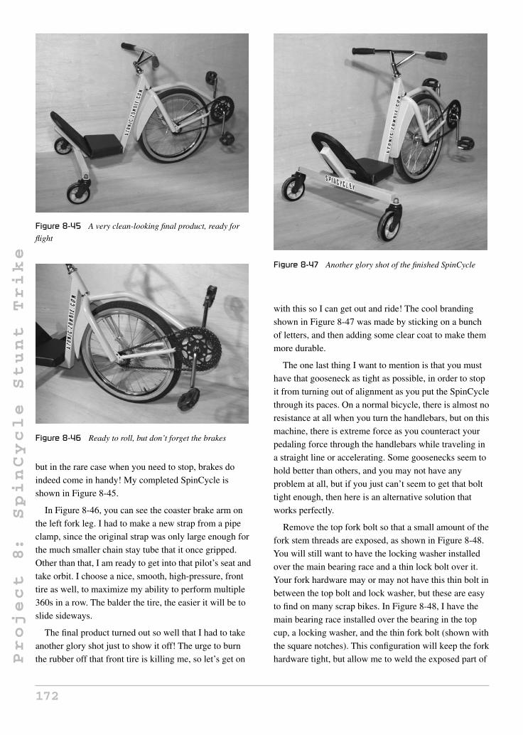
Project
8:
SpinCycle
Stunt
Trike
Figure 8-45 A very clean-looking final product, ready for
flight
Figure 8-46 Ready to roll, but don’t forget the brakes
but in the rare case when you need to stop, brakes do
indeed come in handy! My completed SpinCycle is
shown in Figure 8-45.
In Figure 8-46, you can see the coaster brake arm on
the left fork leg. I had to make a new strap from a pipe
clamp, since the original strap was only large enough for
the much smaller chain stay tube that it once gripped.
Other than that, I am ready to get into that pilot’s seat and
take orbit. I choose a nice, smooth, high-pressure, front
tire as well, to maximize my ability to perform multiple
360s in a row. The balder the tire, the easier it will be to
slide sideways.
The final product turned out so well that I had to take
another glory shot just to show it off! The urge to burn
the rubber off that front tire is killing me, so let’s get on
Figure 8-47 Another glory shot of the finished SpinCycle
with this so I can get out and ride! The cool branding
shown in Figure 8-47 was made by sticking on a bunch
of letters, and then adding some clear coat to make them
more durable.
The one last thing I want to mention is that you must
have that gooseneck as tight as possible, in order to stop
it from turning out of alignment as you put the SpinCycle
through its paces. On a normal bicycle, there is almost no
resistance at all when you turn the handlebars, but on this
machine, there is extreme force as you counteract your
pedaling force through the handlebars while traveling in
a straight line or accelerating. Some goosenecks seem to
hold better than others, and you may not have any
problem at all, but if you just can’t seem to get that bolt
tight enough, then here is an alternative solution that
works perfectly.
Remove the top fork bolt so that a small amount of the
fork stem threads are exposed, as shown in Figure 8-48.
You will still want to have the locking washer installed
over the main bearing race and a thin lock bolt over it.
Your fork hardware may or may not have this thin bolt in
between the top bolt and lock washer, but these are easy
to find on many scrap bikes. In Figure 8-48, I have the
main bearing race installed over the bearing in the top
cup, a locking washer, and the thin fork bolt (shown with
the square notches). This configuration will keep the fork
hardware tight, but allow me to weld the exposed part of
172
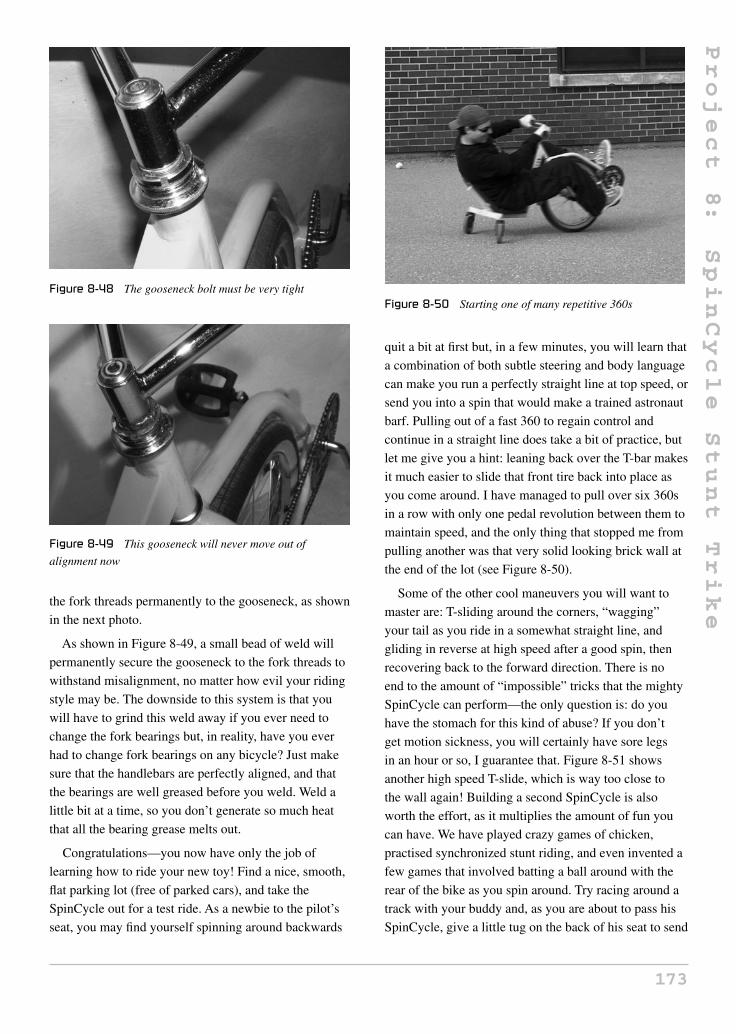
Project
8:
SpinCycle
Stunt
Trike
Figure 8-48 The gooseneck bolt must be very tight
Figure 8-49 This gooseneck will never move out of
alignment now
the fork threads permanently to the gooseneck, as shown
in the next photo.
As shown in Figure 8-49, a small bead of weld will
permanently secure the gooseneck to the fork threads to
withstand misalignment, no matter how evil your riding
style may be. The downside to this system is that you
will have to grind this weld away if you ever need to
change the fork bearings but, in reality, have you ever
had to change fork bearings on any bicycle? Just make
sure that the handlebars are perfectly aligned, and that
the bearings are well greased before you weld. Weld a
little bit at a time, so you don’t generate so much heat
that all the bearing grease melts out.
Congratulations—you now have only the job of
learning how to ride your new toy! Find a nice, smooth,
flat parking lot (free of parked cars), and take the
SpinCycle out for a test ride. As a newbie to the pilot’s
seat, you may find yourself spinning around backwards
Figure 8-50 Starting one of many repetitive 360s
quit a bit at first but, in a few minutes, you will learn that
a combination of both subtle steering and body language
can make you run a perfectly straight line at top speed, or
send you into a spin that would make a trained astronaut
barf. Pulling out of a fast 360 to regain control and
continue in a straight line does take a bit of practice, but
let me give you a hint: leaning back over the T-bar makes
it much easier to slide that front tire back into place as
you come around. I have managed to pull over six 360s
in a row with only one pedal revolution between them to
maintain speed, and the only thing that stopped me from
pulling another was that very solid looking brick wall at
the end of the lot (see Figure 8-50).
Some of the other cool maneuvers you will want to
master are: T-sliding around the corners, “wagging”
your tail as you ride in a somewhat straight line, and
gliding in reverse at high speed after a good spin, then
recovering back to the forward direction. There is no
end to the amount of “impossible” tricks that the mighty
SpinCycle can perform—the only question is: do you
have the stomach for this kind of abuse? If you don’t
get motion sickness, you will certainly have sore legs
in an hour or so, I guarantee that. Figure 8-51 shows
another high speed T-slide, which is way too close to
the wall again! Building a second SpinCycle is also
worth the effort, as it multiplies the amount of fun you
can have. We have played crazy games of chicken,
practised synchronized stunt riding, and even invented a
few games that involved batting a ball around with the
rear of the bike as you spin around. Try racing around a
track with your buddy and, as you are about to pass his
SpinCycle, give a little tug on the back of his seat to send
173

Project
8:
SpinCycle
Stunt
Trike
Figure 8-51 A photo just can’t capture the fun of riding a
SpinCycle
him wildly out of control. The amount of fun is really
endless.
The next day after your first encounter with the
SpinCycle will yield sore muscles that you didn’t even
know you had! Vigorous riding is truly a full body
workout, considering you have to use your upper body as
well as your legs to control the vehicle. I put so many
miles on my first SpinCycle that I had to replace the
caster wheels. I guess shopping carts were never intended
for hitting the pavement at 20 miles per hour. There are
pneumatic tire caster wheels available as well, and in the
future I may make another SpinCycle or convert this one
to test them out. Figure 8-52 shows a non-moving
SpinCycle shot—something that is rare indeed.
By now you probably know what I mean when I say
that the SpinCycle may be the most fun you will ever
have on three wheels. Make sure to scoot on over to our
website (that’s the address shown on the back of the
Figure 8-52 The SpinCycle is crazy, yet comfortable
Figure 8-53 You have to experience the SpinCycle to really
appreciate it
truck in Figure 8-53) when you have some photos of
your SpinCycle, because I always enjoy seeing what
other garage hackers have done. The next project is
another fun ride that also has a practical purpose.
174

Project
9:
UCan2
HandCycle
Project 9: UCan2 HandCycle
When you build creative bicycles and ride them on a
regular basis, you will often find yourself pulled over by
an interested cyclist or fellow garage hacker to answer
some questions about your creation. Often I am asked if
I built it, how much it costs, or if I would consider
building a custom cycle for someone else who may need
something a little different, due to physical limitations
such as a bad back or some type of limited mobility.
There seemed to be a large enough demand for
upper-body-powered vehicles that I decided to search the
Internet to see what was available, and why these people
had just not purchased a ready-to-ride cycle to suit their
needs. The answer was clearly cost.
For about $2,000 or more, you could indeed purchase
a very basic hand-powered trike, but this seemed
extremely steep for a trike that was made of little more
than a few feet of steel tubing and some off-the-shelf
bicycle parts. Not only was the price out of reach for
many people, but the actual design of many of these
trikes was better suited to the professional rider who
wanted performance parts such as disc or drum brakes,
an internally geared hub, and fancy, cambered rear
wheels with the best hubs money could buy. Ironically,
this also made for a bulky and heavy trike that looked
more like a wheelchair with a bicycle front end thrown
on the front, not something cool for younger riders.
I had the chance to closely examine a handcycle at a
children’s center, and could not understand how such a
unit would cost $2,500. In fact, if you compared it to
a bicycle with similar quality parts and engineering, it
would be on a par with a $100 department store kids’
bicycle. I understand that demand may be lower than that
of a standard two-wheeled bike, but I felt that this still
did not justify the inflated cost, especially when
combined with the fact that the unit had obvious
transmission flaws that should have been worked out.
I decided that I could build a handcycle of better quality
for a cost 10 times less than the unit I was examining,
and the end result would be a stronger, sportier-looking
trike that could be easily repaired using standard bicycle
parts, and carried up and down stairs by any caregiver.
The result was the creation of UCan2, a cross between a
freestyle BMX bicycle and a handcycle that cost well
under $500 with all new parts used.
Most handcycles use a pair of wheelchair type hubs on
the two rear wheels, which are either spoked to bicycle
rims or left as radial spoked wheelchair wheels. This
causes the price of manufacturing the trike to skyrocket,
since a decent pair of aluminum wheelchair hubs may
cost $200 a piece. These wheels are often cambered
(leaning inwards), due to the fact that they really are not
the best type of wheels to use on a trike that may be
moving fast enough around corners to take the side
loading demands placed on them. After all, they were
originally designed for hand-powered wheelchairs. Some
manufacturers claim that these cambered wheels are a
sign of high quality, and you should want them. Most
people I show them to say they look like wheelchair
wheels. The three 20-inch wheels shown in Figure 9-1
include two front wheels from a freestyle BMX bicycle
which have 48 spokes and 14-mm-thick axles. The other
wheel is a typical coaster brake hub wheel used on many
kids’ bicycles which allows the rider to simply pedal in
reverse to activate the brake. The two front wheels
which will be mounted as rear wheels on our trike are
only slightly heavier than the expensive wheelchair
wheels, but are many, many times stronger. Each wheel
will probably cost you about $30 brand new from a
bicycle shop.
There are two reasons for choosing the two freestyle
rims as the rear wheels on our handcycle. First, the
14-mm axles are so tough that they can easily be held in
place by one side without any possibility of ever bending
175Copyright © 2008 by The McGraw-Hill Companies, Inc. Click here for terms of use.

Project
9:
UCan2
HandCycle
Figure 9-1 You will need three wheels: two fronts and one
coaster brake
them, even if your rider has a need for speed and high
adrenaline riding. Second, the freestyle rim is very easily
identified by the younger crowd as being “cool,” so your
handcycle pilot will look like they want to ride the
UCan2, rather than look like they have to. When you’re
young, these things matter. Let’s face it—these things
always matter at any age!
As you can see in Figure 9-2, the 14-mm axle
shown in the left dwarfs the standard thickness axle
shown on the right. I can assure you that the standard
axle on the right will not hold up if held by one side of
the axle, even if your rider weighs less than 80 pounds,
so don’t even bother trying it, or your wheels will fold
over within the first few rides. The 14-mm axles on the
other hand are indestructible, and could easily take
400 pounds when used on a trike. These axles are
commonly used on pedicabs that carry two or more
Figure 9-2 14-mm axle on the left; standard rear axle on the
right
Figure 9-3 A standard coaster brake hub
adults right between them, which is why the UCan2 has
no problem with a friend hitching a ride on the rear of the
frame.
The coaster brake wheel shown in Figure 9-3 will be
used as our front drive wheel, and since it is held on by
both ends of the axle, it does not require such a beefy
axle as the rear wheels do. The coaster brake hub also
allows very simple operation of the handcycle by
allowing the rider to pedal forward to drive, and pedal in
reverse to slow down or stop. Handcycles that have
lever-operated brakes force the rider to remove one hand
from the pedals and reach for the lever, which has to be
mounted somewhere on the frame, which is a bad idea.
Can you imagine steering and pedaling a cycle with only
one hand as you precariously reach around for a brake
lever? Try that in an emergency situation and things will
likely end badly.
A coaster brake hub is easily identified by the large
can-like hub and the steel arm opposite the drive
sprocket. This steel arm is secured to the frame and acts
as a transfer between your braking force and the frame.
If you do a little digging like I did, you will be able to
find three matching rims that give the handcycle a very
professional and finished look. The black rims with
brushed aluminum edges are the big style right now, and
are instantly identified as being Freestyle wheels.
When choosing tires for your wheels, keep in mind
that the heavier the tread, the more rolling resistance
there will be, so find rear tires with as little tread as
possible, and a front tire with minimal tread. Surprisingly
enough, a tire with an aggressive tread will not give you
any advantage over one with no tread at all, unless your
176

Project
9:
UCan2
HandCycle
Figure 9-4 Heavy tire tread is not necessary
Figure 9-5 Cut two plates from the flat bar
terrain is very rough such as gravel or dirt. I chose three
similar tires, as shown in Figure 9-4, each with a rating
of 75 psi, and minimal tread to keep the rolling resistance
down to a minimum. If your rider is planning on hitting
the skate parks, then spend the extra few bucks on brand
name tires—these are way cool, so I am told!
Since the rear wheels on the UCan2 are held directly
by one side of their axles, there is no need for any special
bearings or rear transmission hardware, just a place to
bolt the axles. Figure 9-5 shows two rectangular pieces
cut to 2.75 × 1.5 inches from a length of 3/16-inch-thick
flat bar. These will serve as mounting tabs for our rear
axles, as will soon be shown. If you cannot find flat bar
of exactly 3/16-inch thickness, then substitute the closest
flat bar you can find without going under that. These two
parts are so small that a little extra thickness will not
have any impact on the final weight of the handcycle.
The corners of the axle mounting tabs are rounded off
using a grinder so that there is no chance of being cut on
the sharp edges (see Figure 9-6). Even though the tabs
are well out of reach, who knows what kids may try to do
Figure 9-6 Round off the corners
when out riding? Mark a point half an inch from each
end of the tab and stamp a hole with a hammer and punch
for drilling. A neat trick to make both tabs exactly the
same size is to grind them into shape together in the vice
at the same time.
14 mm is not exactly a standard size drill bit to have
lying around the shop, so you may have to take the
mounting tabs to a buddy or machine shop to be drilled.
14 mm is exactly .55 of an inch, so you could get away
with a 9/16-inch drill bit to make the holes, as this will be
pretty close. I did not have a 14-mm drill bit, and even if
I did, it would not fit into the chuck on my little hand
drill, so I purchased a more commonly available
9/16-inch drill bit and ground down the shank with a
grinder so it would fit into my hand drill. I know that it’s
an ugly hack, but I have used it many times to drill holes
for 14-mm axles, and it works perfectly. The drilled
plates are shown in Figure 9-7.
If you do take the axle mounting tabs to be drilled,
bring along one of the wheels just to make sure that the
hole is not undersized. You could hand file the hole if it
were just a bit too small, but this is annoying, since the
3/16-inch-thick plate is fairly thick for hand filing. If you
are using a 9/16-inch drill bit, the axle will definitely fit
through the hole. These 14-mm axles will have ample
length sticking out from each side, since they are made to
hold those freestyle stunt pegs in place. Shown in
Figure 9-8 is the tab securely bolted to the 14-mm axle.
With the exception of a few standard bicycle parts, the
entire trike frame is made from a few feet of 1.5-inch
mild steel square tubing with a 1/16-inch wall thickness.
This tubing can be ordered from any steel supplier and is
177

Project
9:
UCan2
HandCycle
Figure 9-7 Drill the 14-mm axle holes
Figure 9-8 Checking the axle holes
very easy to cut and weld. Steel suppliers like to rate
tubing wall thickness using a gauge number, so 1/16-inch
wall tubing will be called 16-gauge tubing, and although
there is a slight difference between the two, your best bet
is to tell them you want a length of 1.5-inch square
tubing with a wall thickness as close to .0625 of an inch
(1/16) as you can get. Round tubing should be avoided
for this project, as it will be much more difficult to cut at
the correct angles, and would most likely be out of
alignment after all the welding is completed due to heat
distortion. As shown in Figure 9-9, the rear part of the
frame which will hold the two rear wheels is just a
22-inch long piece of tubing cut square at each end. This
part of the frame will be called the “rear frame tube”
from now on. Try to make the cuts at each end as square
as possible, since this will affect the alignment of the rear
wheels as you will soon see.
Figure 9-9 The rear frame tube
Figure 9-10 Weld the axle mounting tabs to the rear
frame tube
The axle mounting tabs are welded directly to each
end of the rear frame tube, as shown in Figure 9-10.
Notice how they cap off the open ends of the tube, as
well as create a sturdy mounting point for the axles on
the rear wheels. In Figure 9-10, I have welded on only
three sides of the joint, leaving the joint just below the
axle mounting hole untouched. It is important not to weld
this part of the joint, as the extreme heat from the
welding process will cause the axle mounting tab to bend
slightly towards the weld area, throwing your two rear
wheels out of parallel alignment. No amount of clamping
will cure this warping, and there is no great strength
benefit from welding this part of the joint anyhow, so
make sure to leave it.
Once the three open sides of the joint are welded,
grind the area clean and round off all of the sharp corners
as best you can without taking off too much of the metal.
The corners do not have to be rounded off too much to
make them perfectly round, just enough so that there is
no possible way to cut yourself on any part of the frame
if you were to come in contact with it. Figure 9-11 shows
my completed rear frame tube after finishing up with a
sanding disc.
178

Project
9:
UCan2
HandCycle
Figure 9-11 Removing all sharp edges from the welded area
Figure 9-12 Checking rear wheel alignment
Once you have welded the axle mounting tabs to each
end of the rear frame tube, bolt the rear wheels in place,
as shown in Figure 9-12. If both the mounting tabs are
parallel, the two wheels will roll in a nice straight line
without any apparent wheel scrubbing. Test this by
pushing down on the tube while you walk along the
floor—there should be no rubbing sound.
Figure 9-13 shows the completed rear of the UCan2
HandCycle. Although there is little more than a few feet
of tubing and a pair of wheels, this setup could easily
carry 300 pounds or more without any problem at all.
Yes, this would form the perfect backbone for a nice
bicycle trailer or load carrying vehicle, but that’s a
project for another day.
To connect the rear frame tube to the head tube and
front forks, we will need two more short lengths of the
same 1.5-inch square tubing used for the rear of the
frame. The tube that runs horizontally along the ground
will be called the “middle frame tube,” and the tube that
Figure 9-13 Both rear wheels should be parallel
Figure 9-14 The dimensions for the middle frame tube
connects the middle frame tube to the head tube will be
called the “front frame tube.” So basically the UCan2 is
made from three lengths of 1.5-inch square tubing: the
front tube, the middle tube, and the rear tube (already
completed). The middle frame tube is shown in
Figure 9-14 as an 18-inch-long square tube with a
23-degree angle cut at one end. Since this tube will be
welded directly to the rear frame tube, the other end is
cut off at a 90-degree angle.
Mark and cut the 23-degree angle using whatever
method works best for you. As shown in Figure 9-15,
I used an adjustable square and an angle finder to get this
measurement. A chop saw is a better way to cut square
Figure 9-15 Visualizing rear wheel placement
179

Project
9:
UCan2
HandCycle
Figure 9-16 Dimensions for the front frame tube
tubing at specific angles, but since I only use a handheld
angle grinder, hand drill and basic welder to create
everything I make, I had to mark the tubing by hand and
then follow the marks using a cut-off disc. Do not worry
about precision here, as even a few degrees either way
will produce a perfectly working handcycle and, as
always, feel free to modify the design for whatever
reason you may have once you understand how all the
parts fit together.
The front frame tube is another length of 1.5-inch
square tubing with a total length of 15 inches and
23-degree cuts at each end, as shown in Figure 9-16.
Notice that both angles are parallel to each other. Use the
same method that you used to cut the 23-degree angle in
the other tube and repeat the process for both ends of the
tube. You now have three main frame tubes, so the rest of
the handcycle will come together quickly from this
point on.
The reason for the 23-degree cut at the ends of the
middle frame tube and front frame tube is this. When
welded together, they will form a 134-degree angle, as
shown in Figure 9-17. It does not matter which end of the
front tube meets the middle tube, since both ends have a
23-degree cut facing the same direction. When placed on
a flat surface for tack welding, your frame tubes should
Figure 9-17 The front tube and middle tube join together
look like the ones shown in Figure 9-17, with an angle
very close to 134 degrees between them. Clamp or weigh
down both tubes on a flat surface, and then tack weld the
two top corners of the weld and in the center of each
visible joint. Once tack welded, pick up the two tubes
and visually inspect them to make sure that they are
aligned and at the correct angle. If you are satisfied with
the tack welded parts, fully weld the top and bottom
joints, and then do the two sides. This order of welding
will help minimize side-to-side distortion of the frame.
Weld all the way around the joint, as shown in
Figure 9-18, creating a solid and pinhole-free weld
between the two tubes. The 134-degree angle formed
between the two tubes may vary by a degree or two after
welding, but this will not be a problem. If you look at the
two parts from a bird’s eye view, they should appear to
form a straight line.
If you are a welder who likes to grind all welds flush
for appearance, then do so sparingly here, as this needs to
be the strongest weld on the entire handcycle because it
joins the two main halves of the trike together. As shown
in Figure 9-19, I did my best to make a nice-looking bead
of weld so that no grinding would be necessary in order
Figure 9-18 Weld the entire joint
Figure 9-19 A good solid weld is needed here
180

Project
9:
UCan2
HandCycle
Figure 9-20 Joining the front and rear parts of the frame
to avoid weakening the joint. If you do need a little bit of
grinding to make the weld look better, only take off as
much material as needed, and weld any pinholes or open
spots that may have appeared after grinding. If welding is
done properly, the UCan2 frame will be amazingly
tough. I have done things to this handcycle that would
certainly void the warranty of any commercially
produced handcycle, and doubt that I could intentionally
break this cycle without first breaking myself!
Now that the front tube and middle tube have
become one, the last main frame weld to be made will be
the one that joins the rear tube to the back end of the
middle tube, as shown in Figure 9-20. The rear frame
tube and middle frame tube will form a T-shape, with a
90-degree angle between them. I simply laid the parts on
a flat surface, marked the center point on each tube, and
then placed a solid tack weld right at this point. The
frame was then carefully flipped over so that another tack
weld could be placed on the underside of the joint. Once
the two tack welds that secure the frame tubes are in
place, place a square along the two parts to make sure
that there is a 90-degree angle between them. A small tap
of a hammer will easily force the tubing into perfect
alignment.
When you have a good 90-degree angle between the
rear frame tube and middle frame tube, add two more
tack welds to the joint at the top corners, and do one last
alignment check with your square. If alignment is good,
flip the frame over and weld the entire length of the
bottom of the joint, and then do the same on the top, but
do not weld the sides of the joint. The sides of the joint
are not to be welded or your rear frame tube will be
pulled out of 90 degrees, causing your handcycle to track
in an awkward fashion. No amount of clamping will stop
this distortion and, as you will soon see, the sides of the
Figure 9-21 Do not weld the sides of the joint
frame will be getting gussets for added strength, so this
weld is not needed. Figure 9-21 shows the completed
weld between the rear frame tube and the rest of the
frame tubing. Note the sides of the joint are not welded,
and they will not be welded.
Although it would take a serious amount of force to
damage the handcycle frame, even with the rear frame
joint only welded in two places, you just never know
what ambitious riders might try to do, so a few small
gussets will make the frame virtually indestructible. The
exact size, shape, and type of steel used for these rear
gussets is not important, so dig into your scrap bin and
use up some of those leftovers and cut-offs. For the
record, the two gussets I have cut in Figure 9-22 are
three inches long and are made from scraps of
1/8-inch-thick flat bar with a width of half an inch.
Round tubing, square tubing, or even cut-off bolts will
also work.
The rear frame gussets will install at the 90-degree
corner between the rear frame tube and the middle frame
tube, as shown in Figure 9-23. The size and shape of the
Figure 9-22 Rear frame gussets
181

Project
9:
UCan2
HandCycle
Figure 9-23 Installing the rear gussets
Figure 9-24 Weld both rear frame gussets in place
gusset are not critical, but do try to round off any sharp
edges, and avoid creating tiny spaces that a finger could
become lodged in.
There is no special procedure for welding the rear
frame gussets in place; just try to make them even on
both sides of the frame so that everything looks balanced.
There is nothing worse than a frame that is
non-symmetrical. Figure 9-24 shows my two small, rear
frame gussets after welding both sides of the joint. The
rear of the frame is now stronger than it would ever need
to be for any type of riding your test pilot may want to
do. Did I mention the time I took the UCan2 over a jump
with a brave stunt rider standing on the rear of the frame
in such a way that we landed on two wheels? Yes, this
handcycle is really that durable! If you tried anything
like this on some of the production models using
radial-spoked wheelchair wheels on the rear, you would
not have a good landing—that is for certain.
Figure 9-25 Front forks and head tube
You will need a pair of 20-inch front forks and a
matching head tube and hardware to complete the front
of the handcycle. Figure 9-25 shows a typical BMX-style
fork set commonly found on any 20-inch kids’ bicycle or
BMX. The head tube and all of the hardware should fit
properly onto the fork stem, and it is also cut from an old
bicycle frame. My head tube is from a 1970s road bike,
and the front forks are from a bent-up kids’ BMX bike,
but they work perfectly together. If your fork threads are
too long for the head tube, just install all the hardware to
make sure that everything fits, then trim off the excess
fork thread with a hacksaw or cut-off disc. If you hold
the head tube in your hand, the forks should spin around
with practically no friction. If they do not, you may have
the bearings installed upside down, or have the wrong
sized fork bearings for the cups (there are two common
sizes available).
Once you scrounge up a decent set of front forks and a
compatible head tube, remove and clean all of the
hardware for inspection. Badly rusted cups or bearings
should be replaced, and forks with badly damaged
threads should be avoided. To stay with the BMX look,
I used the beefiest pair of forks I could find, as shown in
Figure 9-26; they are not really any heavier, they just
look stronger, which is why young people like them.
Clean up any excess stubbage on the dismembered
head tube left over from the original frame, and grind
away all the paint so you don’t fill your garage with
Figure 9-26 Checking the steering hardware
182

Project
9:
UCan2
HandCycle
Figure 9-27 Head tube ground clean
Figure 9-28 Are you feeling strong today?
horrible toxic smoke when you start welding. Clean
metal is much easier to weld than rusty or painted metal,
and it sure smells nicer! Notice the little bit of
gold-colored brazing metal left around the welded area of
my head tube, as shown in Figure 9-27—a sure sign that
this frame was a museum piece before I hacked it.
If you are lucky, the front drive wheel may slide right
into the fork dropouts with only a little effort but, most
likely, you will need to do a little fork leg expanding, as
shown in Figure 9-28. A rear hub is a bit wider than a
front hub most of the time, so you will need to bend apart
the fork legs ever so slightly to make installation of the
drive wheel easier. Depending on the quality of the forks
chosen and the condition of your back, you may be able
to stand on one fork leg while pulling upwards on the
other to get the extra quarter inch needed. Don’t throw
your back out trying to be a hero though; these forks are
stronger than they look. I was almost at my physical limit
when expanding them this way.
You could crank the legs apart with a long lever made
with 2 × 4s, or place some type of screw between them
and crank it with a wrench. There are many ways to get
Figure 9-29 Testing the front wheel fit
this job done, but do be careful not to pull the fork legs
apart too much in one mighty tug, or you will have to
squash them back together, and this could weaken the
welded area. I did this the manual way, pulling up on the
forks little by little, and checking the distance with the
actual wheel until it fit properly.
Once the fork legs are forced apart a little bit, the
wheel will drop right in place, as shown in Figure 9-29.
It’s best to install the wheel by hand so you don’t scratch
up the forks once they are painted. This is why they are
pulled apart permanently, rather than just forcing the
wheel into the dropouts by prying about with a
screwdriver. When installed, the drive sprocket will be
on the right side of the frame, just like it was on a regular
two-wheeled bicycle.
Once the front wheel has made friends with the front
forks, reinstall the head tube and all the bearing
hardware. At this point, you will also want the front tire
fully inflated, since we will be using the front wheel and
forks as a guide to set up the correct head tube angle.
As shown in Figure 9-30, find an object to place the
underside of the frame on so that the middle frame tube
is roughly parallel to the ground. I found a 9.75-inch-tall
bucket that was just perfect for this job. The middle
frame tube does not have to be exactly parallel with the
ground; just get it as close as possible. We may be lifting
or dropping the frame to match the head tube in the next
few steps anyhow. Place the head tube up against the top
of the front frame tube and secure the front wheel from
rolling away, as shown Figure 9-30.
183

Project
9:
UCan2
HandCycle
Figure 9-30 Setting up the head tube angle
Figure 9-31 Correct head tube angle
The proper head tube angle will be approximately
64 degrees. This angle is measured from the angle
formed between the ground and the head tube, as shown
in Figure 9-31. This angle should be fairly close to the
angle already cut at the end of the front frame tube,
which is why 23 degrees was specified back in
Figure 9-14. Don’t worry about placing the head tube at
the exact angle right now; this was just a trial mock-up.
The actual installation will occur in the next few steps
once the top of the front frame tube is ground properly.
The top of the front frame tube that must mate with the
head tube will need to be ground out, as shown in
Figure 9-32, in order to make a proper joint for welding.
Figure 9-32 Grinding out the head tube joint
Figure 9-33 Checking head tube alignment
Simply trace a circle the same diameter as the head tube
shell on the top and bottom of the tube, then grind out the
area using an angle grinder or hand file. Both cutouts
should be the same depth on both sides of the tube, in
order to keep the 64-degree angle constant. Make the
cuts as equal as you can by eye, but don’t worry about
exact precision, as you will have lots of room to work
with when it comes time to weld.
With the top of the front frame tube ground out to
cradle the head tube properly, set the front end back in
place, as shown in Figure 9-33. The three wheels should
all be parallel when viewed directly from the front, and
the head tube angle should be close to 64 degrees. If the
top of the front tube is too low to meet up with the lower
part of the head tube, just prop the frame up a little higher
until it fits. It’s not essential that the middle frame tube
be exactly parallel to the ground, as this is just a guide.
The proper place to weld the top of the front frame
tube to the head tube is a half inch from the bottom of the
head tube, as shown in Figure 9-34. I like to make the
first few tack welds while the front wheel is in place and
the frame is supported by the underside to recheck
alignment before any real welding is done. A few taps of
the hammer will allow for slight alignment changes
while there are only two or three small tack welds at the
joint. Ensure that you look at the frame from all angles to
ensure that the wheels are aligned correctly. All three
wheels should be pointing in the same direction when
viewed from top, front, and rear. When you are happy
184

Project
9:
UCan2
HandCycle
Figure 9-34 Tack weld the head tube
with the alignment, do a little more welding until you can
safely handle the frame to remove the forks from the
head tube.
With the head tube properly aligned and securely tack
welded to the front tube, remove the forks and finish up
the welding by starting at the top and bottom of the
joint, and then by welding both sides so it looks like the
one shown in Figure 9-35. Make sure that all the welding
is solid, and avoid grinding this area too much, just like
you did at the weld between the rear frame tube and
middle tube. This is another weld that needs to be strong.
Now is also a good time to fill in any holes in the head
Figure 9-35 Completed head tube welding
Figure 9-36 You now have a rolling frame
tube that may be left over from the removal of the
original bicycle frame tubing. To fill the holes, make a
single pass around the edge of the hole, chip the flux,
then repeat until the entire hole is covered. Once
covered, simply grind the area flush to remove all traces
of the original hole.
Well done, as you now have a rolling frame like the
one shown in Figure 9-36. This is a great place to be
when building any wheeled vehicle. The rest of the
UCan2 HandCycle will be a lot easier, since there are no
critical welds or alignments to be done from here on.
The UCan2 places the pedals where the handle bars
would be on a regular bicycle by connecting a bottom
bracket (actually on the top here) to an extended
gooseneck. I doubt that you will find a gooseneck with
the required length to place the top 6.5 inches above the
fork hardware, so we will make one from a standard
bicycle gooseneck and an old seat post. Any old steel
gooseneck can be used to create our new longer version,
but do make sure that it fits properly into the fork stem
you are using because there are two common sizes used.
If your gooseneck feels loose in the fork stem, then it is
the wrong size. There will be no mistake: it will either fit
perfectly, be way too loose, or not fit at all. Figure 9-37
shows the old BMX-style gooseneck I found in my parts
Figure 9-37 Gooseneck to be cut
185

Project
9:
UCan2
HandCycle
Figure 9-38 Cut the top from the gooseneck
bucket for chopping. Only the stem of the gooseneck will
be used, so the condition of the clamp and hardware is
not important. The stem needs to be straight, free of
cracks, and made of steel.
Cut the clamp hardware away from the gooseneck
stem, as shown in Figure 9-38, leaving just enough
material to weld the extension tube to. If you are using a
modern mountain-bike-style gooseneck, it will most
likely be painted black and have a single clamp held to
the stem by an arm. Either style will work, since it is only
the stem we are after.
The actual gooseneck extension tube can be made
from a 6.5-inch-long bit of steel seat post tubing,
or any similar diameter and strength tubing. Handy
alternative tubing can be found on mountain bike
handlebars, bicycle frame seat tubes, or even some
electrical conduit. As long as the tubing is not thinner
than the gooseneck stem material, then it will be strong
enough. As shown in Figure 9-39, cut the tube to a
length of 6.5 inches.
The gooseneck extension tube is welded to the cut
gooseneck stem, as shown in Figure 9-40. Grinding the
leftover stem material to the shape of the extension tube
before welding makes this task a lot easier, and will
produce a much nicer-looking and distortion-free weld.
Figure 9-39 A seat post will be used to lengthen the neck
Figure 9-40 Grind the area to be welded first
Figure 9-41 Gooseneck extension fully welded
A tack weld at the top near the gooseneck bolt hole is a
good start that will let you visually inspect and realign
the two pieces so they are perfectly parallel before
welding the entire joint.
When you have the gooseneck extension tube in line
with the gooseneck stem, finish all the welding, making
sure that the weld is strong and free of holes
(Figure 9-41).
The bottom bracket will be placed on the end of the
gooseneck extension tube in the UCan2 so the cranks can
serve as both a source of motive power and steering
at the same time. You will need to hack up another part of
the bicycle frame you have been butchering to acquire
the three-piece bottom bracket, as shown in Figure 9-42.
Figure 9-42 A bottom bracket cut from an old frame
186
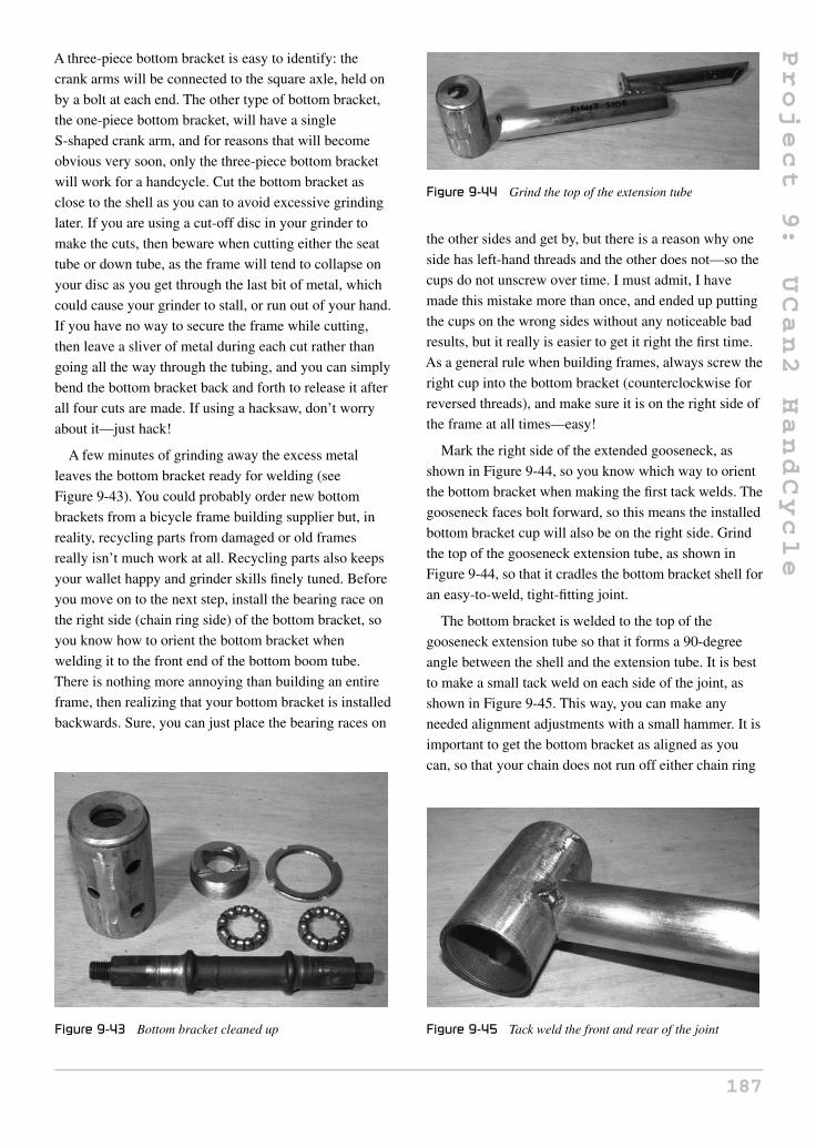
Project
9:
UCan2
HandCycle
A three-piece bottom bracket is easy to identify: the
crank arms will be connected to the square axle, held on
by a bolt at each end. The other type of bottom bracket,
the one-piece bottom bracket, will have a single
S-shaped crank arm, and for reasons that will become
obvious very soon, only the three-piece bottom bracket
will work for a handcycle. Cut the bottom bracket as
close to the shell as you can to avoid excessive grinding
later. If you are using a cut-off disc in your grinder to
make the cuts, then beware when cutting either the seat
tube or down tube, as the frame will tend to collapse on
your disc as you get through the last bit of metal, which
could cause your grinder to stall, or run out of your hand.
If you have no way to secure the frame while cutting,
then leave a sliver of metal during each cut rather than
going all the way through the tubing, and you can simply
bend the bottom bracket back and forth to release it after
all four cuts are made. If using a hacksaw, don’t worry
about it—just hack!
A few minutes of grinding away the excess metal
leaves the bottom bracket ready for welding (see
Figure 9-43). You could probably order new bottom
brackets from a bicycle frame building supplier but, in
reality, recycling parts from damaged or old frames
really isn’t much work at all. Recycling parts also keeps
your wallet happy and grinder skills finely tuned. Before
you move on to the next step, install the bearing race on
the right side (chain ring side) of the bottom bracket, so
you know how to orient the bottom bracket when
welding it to the front end of the bottom boom tube.
There is nothing more annoying than building an entire
frame, then realizing that your bottom bracket is installed
backwards. Sure, you can just place the bearing races on
Figure 9-43 Bottom bracket cleaned up
Figure 9-44 Grind the top of the extension tube
the other sides and get by, but there is a reason why one
side has left-hand threads and the other does not—so the
cups do not unscrew over time. I must admit, I have
made this mistake more than once, and ended up putting
the cups on the wrong sides without any noticeable bad
results, but it really is easier to get it right the first time.
As a general rule when building frames, always screw the
right cup into the bottom bracket (counterclockwise for
reversed threads), and make sure it is on the right side of
the frame at all times—easy!
Mark the right side of the extended gooseneck, as
shown in Figure 9-44, so you know which way to orient
the bottom bracket when making the first tack welds. The
gooseneck faces bolt forward, so this means the installed
bottom bracket cup will also be on the right side. Grind
the top of the gooseneck extension tube, as shown in
Figure 9-44, so that it cradles the bottom bracket shell for
an easy-to-weld, tight-fitting joint.
The bottom bracket is welded to the top of the
gooseneck extension tube so that it forms a 90-degree
angle between the shell and the extension tube. It is best
to make a small tack weld on each side of the joint, as
shown in Figure 9-45. This way, you can make any
needed alignment adjustments with a small hammer. It is
important to get the bottom bracket as aligned as you
can, so that your chain does not run off either chain ring
Figure 9-45 Tack weld the front and rear of the joint
187

Project
9:
UCan2
HandCycle
Figure 9-46 Checking bottom bracket alignment
when pedaling. Don’t forget which side of the gooseneck
is the right side, so you can get the right side of the
bottom bracket installed.
Do a close visual inspection of the bottom bracket
once it has been tack welded to the gooseneck extension
tube and make any necessary adjustments. From the top,
the assembly should look like the one shown in
Figure 9-46. Notice the good parallel alignment, as well
as the position of the gooseneck bolt towards the front.
With the two parts aligned properly, fill in the welds at
the top and bottom of the joints before you do any of the
welding along the sides, in order to reduce any distortion
due to heat.
With the top and bottom of the joint securely welded
and alignment looking good, you can proceed to weld the
entire length of the joint, as shown in Figure 9-47. As
always, make the weld strong, and be sure to fill in any
gaps or pinholes when you are done.
The new extended gooseneck and bottom bracket
combination will now be known as the “drive system.”
Figure 9-47 Bottom bracket welding completed
Figure 9-48 Install the bottom bracket
Place the drive system in the fork stem and tighten it up
so that it is aligned properly with the front wheel—bolt
forward (see Figure 9-48). You can also install the crank
axle and all the bearings back into the bottom bracket,
making sure that one side of the axle is actually slightly
longer then the other. The longer side of the axle is the
drive side, so it will go in first. Bearings are also installed
so that the balls face the cups. Do not bother to grease up
the bearings yet because everything will have to come
apart for painting soon.
To make the UCan2 as light and simple as possible
to operate, a coaster wheel is used, which means there
is no need for a multiple-speed crank set, or any
type of shifting mechanism. The lack of shifters and
levers is a good thing for those who are riding for the first
time, or just want to get out and have fun on a tough,
lightweight, easy-to-operate cycle. Just like many
188

Project
9:
UCan2
HandCycle
Figure 9-49 Reduce the crank set to a single gear
single-speed kids’ bicycles, a medium-sized front (drive)
chain ring of between 38 and 42 teeth is used. Since most
two- or three-speed chain rings are held together by the
mid-sized chain ring as the main support, you can
simply cut or unbolt the larger and smaller chain
rings to leave only the one you want. A perfect style of
chain ring to hack up is the old aluminum arm style
found on old road bikes, as shown in Figure 9-49. You
can simply unbolt or hacksaw the larger chain ring from
the set to leave a nice light aluminum arm crank set with
a single chain ring of 38 or 42 teeth. For an adult who
wants a handcycle for some serious long-distance travel,
you will want as many gears as found on a regular
bicycle, but this added complexity is certainly not worth
it for this project. From personal experience, this
handcycle will travel as fast you will ever need for
typical park or street riding. With this gearing suggested,
the UCan2 will travel as fast as any single-speed kids’
bicycle.
We needed the three-piece crank set and bottom
bracket so that the crank arms can be placed on the
square axle to point in the same direction, as shown in
Figure 9-50. It may seem odd to place them this way, but
if you think about how power is delivered to the drive
wheel while at the same time needing decent control of
the trike, it will seem more logical. You could certainly
install the crank arms in whatever orientation you like
and give it a try, but it is very obvious that there is less
control over the steering and less available power to get
moving if you have to push and pull in a swimming
motion. Feel free to experiment, though.
The handcycle is ready for a transmission to bring that
crank energy to the front wheel, but there are a few issues
Figure 9-50 Crank arms are installed in the same direction
that need to be resolved in order to get the chain to run
properly past the frame tubing and fork leg tubing. If you
simply installed a bicycle chain at this point, it would
work very well until you tried to make a right-hand turn,
which would place the drive side of the chain into the top
frame tubing, creating a nasty rub or chain derailment.
Some handcycles get around this problem by placing the
front wheel and bottom bracket way ahead of the head
tube, but this makes more of a chopper bicycle style than
a handcycle. Although this system works fine on a fast
and low frame, it just wouldn’t suit the design of
the UCan2.
“Drive side” refers to the side of the chain that leaves
the rear of the front wheel sprocket entering the rear of
the drive chain ring; in other words, it is the side of the
chain that is closest to the rider. This is the only part of
the chain that will ever be under any tension because it
transfers your energy into the drive wheel. “Return side”
refers to the side of the chain that exits the drive chain
ring and enters the sprocket on the front wheel. This part
of the chain will almost always be slack, as it never has
any tension nor does it do any work unless the rider back
pedals to engage the brake.
The reason we need to know which side of a chain is
the drive side and which is the return side is so that we
can choose the appropriate pulleys in order to route our
chain around the frame. If you look at the two small
plastic wheels that the return chain pass through on a
typical rear derailleur, you will notice that they are
nothing more than soft plastic wheels running on a steel
pin. This works just fine because the chain just lazily
slips past the wheels with almost zero force. If you tried
to use those plastic wheels on the drive side of a chain,
189
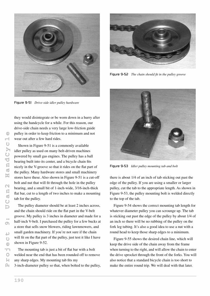
Project
9:
UCan2
HandCycle
Figure 9-51 Drive-side idler pulley hardware
they would disintegrate or be worn down in a hurry after
using the handcycle for a while. For this reason, our
drive-side chain needs a very large low-friction guide
pulley in order to keep friction to a minimum and not
wear out after a few hard rides.
Shown in Figure 9-51 is a commonly available
idler pulley as used on many belt-driven machines
powered by small gas engines. The pulley has a ball
bearing built into its center, and a bicycle chain fits
nicely in the V-groove so that it rides on the flat part of
the pulley. Many hardware stores and small machinery
stores have these. Also shown in Figure 9-51 is a cut-off
bolt and nut that will fit through the hole in the pulley
bearing, and a small bit of 1-inch-wide, 3/16-inch-thick
flat bar, cut to a length of two inches to make a mounting
tab for the pulley.
The pulley diameter should be at least 2 inches across,
and the chain should ride on the flat part in the V-belt
groove. My pulley is 3 inches in diameter and made for a
half-inch V-belt. I purchased the pulley for a few bucks at
a store that sells snow blowers, riding lawnmowers, and
small garden machinery. If you’re not sure if the chain
will fit on the flat part of the pulley, just test it like I have
shown in Figure 9-52.
The mounting tab is just a bit of flat bar with a bolt
welded near the end that has been rounded off to remove
any sharp edges. My mounting tab fits my
3-inch-diameter pulley so that, when bolted to the pulley,
Figure 9-52 The chain should fit in the pulley groove
Figure 9-53 Idler pulley mounting tab and bolt
there is about 1/4 of an inch of tab sticking out past the
edge of the pulley. If you are using a smaller or larger
pulley, cut the tab to the appropriate length. As shown in
Figure 9-53, the pulley mounting bolt is welded directly
to the top of the tab.
Figure 9-54 shows the correct mounting tab length for
whatever diameter pulley you can scrounge up. The tab
is sticking out past the edge of the pulley by about 1/4 of
an inch so there will be no rubbing of the pulley on the
fork leg tubing. It’s also a good idea to use a nut with a
round head to keep those sharp edges to a minimum.
Figure 9-55 shows the desired chain line, which will
keep the drive side of the chain away from the frame
when turning to the right, and will allow the chain to enter
the drive sprocket through the front of the forks. You will
also notice that a standard bicycle chain is too short to
make the entire round trip. We will deal with that later.
190

Project
9:
UCan2
HandCycle
Figure 9-54 Pulley and mounting hardware
Figure 9-55 The chain will clear the fork legs
Test your chain run using a length of bicycle chain
wrapped around the rear of each sprocket and over the
pulley; this will represent the drive side of the chain.
Look at the chain from the top so you can find the
optimal place on the fork leg to align the pulley to be in
the same line as the chain, as it travels in a straight line
from one chain ring to the other. A couple of small tack
welds can be used to secure the pulley mounting tab to
the fork leg tubing, once you have found the optimal
mounting position, as shown in Figure 9-56.
Once you have found the optimal mounting position
for the drive pulley, weld both sides of the tab, as shown
in Figure 9-57, to secure the tab in place. Because the bolt
faces the front wheel, you will likely need to remove the
Figure 9-56 Pulley mounting tab tack welded in place
Figure 9-57 Mounting tab fully welded on both sides
front wheel in order to remove the nut and the pulley, but
it is best to have the tire away from any welding anyhow.
Now that the drive-side pulley is in place, we must
deal with the return side of the chain, which will be under
almost no tension. Because the drive side of the chain
just idles along most of the time, a simple tensioner can
be made by “slicing and dicing” an old rear derailleur
from a road bike or mountain bike. As shown in
Figure 9-58, a short arm rear derailleur is chosen for
hacking, since it is no longer needed, and made mainly of
steel. Practically any steel derailleur can be used to make
this tensioner, as you will see by reading ahead a bit.
The only part of the derailleur we need is the longer
arm with one of the plastic wheels attached and the
spring-loaded pin. Start by drilling or filing off the two
small rivet heads that hold the spring-loaded pin to the
rest of the derailleur. A 1/4-inch drill bit works great for
removing the pins, as shown in Figure 9-59.
191

Project
9:
UCan2
HandCycle
Figure 9-58 An old road bike rear derailleur
Figure 9-59 Removing the derailleur body
Once the pins are removed, you will be left with the
two idler wheels and the spring-loaded pin, as shown in
Figure 9-60. Now remove the bolts on each idler wheel
to release both wheels and the backside of the
derailleur arm.
With the idler wheels removed from the derailleur, cut
the shorter arm off so that only the idler wheel mounting
hole furthest away from the spring-loaded pin will
remain. You should end up with something that looks
similar to what I have in Figure 9-61, although your
derailleur arm may be somewhat longer depending on
what you started with.
The single idler wheel is now replaced using a nut and
bolt that was the same diameter as the original bolt that
held the two arm halves together. As shown in
Figure 9-62, there is only a single arm and idler wheel
remaining on the spring-loaded pin. We now have a
simple spring-loaded chain tensioner. If you have a lot of
small bits around your scrap pile, you could always make
Figure 9-60 Derailleur wheels and spring post
Figure 9-61 Remove the rear wheel mount
Figure 9-62 Bolt the small derailleur wheel in place
your own spring-loaded chain tensioner, but this method
is inexpensive and uses readily available parts.
Find a steel bolt of approximately 2.5 inches in length
and weld the derailleur body to it, as shown in
Figure 9-63. This bolt will serve as a mounting pin to
192
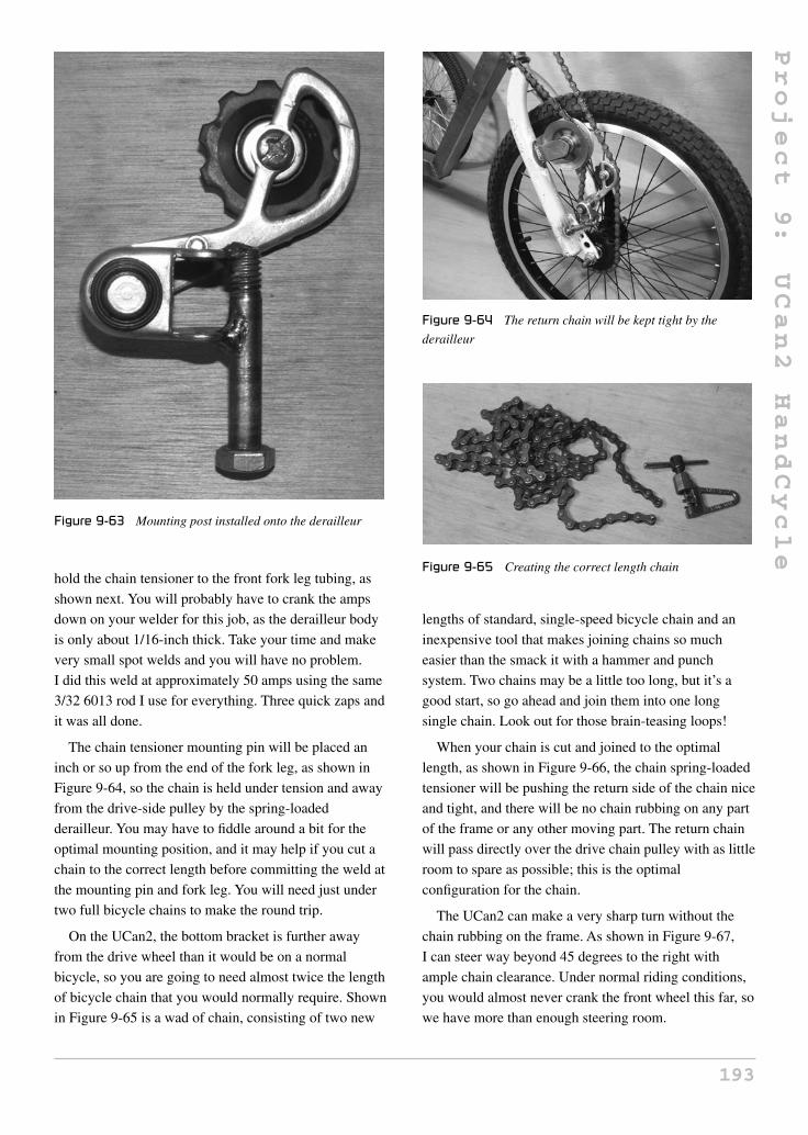
Project
9:
UCan2
HandCycle
Figure 9-63 Mounting post installed onto the derailleur
hold the chain tensioner to the front fork leg tubing, as
shown next. You will probably have to crank the amps
down on your welder for this job, as the derailleur body
is only about 1/16-inch thick. Take your time and make
very small spot welds and you will have no problem.
I did this weld at approximately 50 amps using the same
3/32 6013 rod I use for everything. Three quick zaps and
it was all done.
The chain tensioner mounting pin will be placed an
inch or so up from the end of the fork leg, as shown in
Figure 9-64, so the chain is held under tension and away
from the drive-side pulley by the spring-loaded
derailleur. You may have to fiddle around a bit for the
optimal mounting position, and it may help if you cut a
chain to the correct length before committing the weld at
the mounting pin and fork leg. You will need just under
two full bicycle chains to make the round trip.
On the UCan2, the bottom bracket is further away
from the drive wheel than it would be on a normal
bicycle, so you are going to need almost twice the length
of bicycle chain that you would normally require. Shown
in Figure 9-65 is a wad of chain, consisting of two new
Figure 9-64 The return chain will be kept tight by the
derailleur
Figure 9-65 Creating the correct length chain
lengths of standard, single-speed bicycle chain and an
inexpensive tool that makes joining chains so much
easier than the smack it with a hammer and punch
system. Two chains may be a little too long, but it’s a
good start, so go ahead and join them into one long
single chain. Look out for those brain-teasing loops!
When your chain is cut and joined to the optimal
length, as shown in Figure 9-66, the chain spring-loaded
tensioner will be pushing the return side of the chain nice
and tight, and there will be no chain rubbing on any part
of the frame or any other moving part. The return chain
will pass directly over the drive chain pulley with as little
room to spare as possible; this is the optimal
configuration for the chain.
The UCan2 can make a very sharp turn without the
chain rubbing on the frame. As shown in Figure 9-67,
I can steer way beyond 45 degrees to the right with
ample chain clearance. Under normal riding conditions,
you would almost never crank the front wheel this far, so
we have more than enough steering room.
193

Project
9:
UCan2
HandCycle
Figure 9-66 Chain installed and drive system complete
Figure 9-67 The chain will not rub on the frame during
normal use
Before you give in to the temptation of standing on the
seatless frame for a test run, you must install the brake
arm mounting tab. Without the brake arm held in place,
your axle will turn in the dropouts upon application of
the brake, which could possibly strip the axle threads, or
make your front wheel pop right out—ouch! A simple
brake arm mounting tab can be made from any thin bit of
steel with a hole drilled through it. In Figure 9-68, I just
cut the end of a reflector mounting arm and used that,
since the end was already rounded off, and the correct
size hole was drilled into it.
Bolt the brake arm mounting tab to the brake arm, and
then rotate it counterclockwise until the tab comes into
contact with the fork leg tubing, as shown in Figure 9-69.
Once in the correct place, make two good tack welds,
Figure 9-68 Coaster brake mounting tab
Figure 9-69 Brake mounting tab installed onto the fork leg
then remove the front wheel so the tab can be fully
welded to the fork tubing. Make sure that your front
wheel is aligned properly between the fork legs before
you mount the brake arm tab, or you will be cutting it off
to fix it.
I will admit that the desire to test ride the UCan2 beat
me at this stage, and I duct taped a small bucket to the
back of the frame so I could hop on and take it out for a
blast. What fun it was until the bucket fell off!
Figure 9-70 shows the handcycle ready for a seat.
Depending on your intended rider’s needs, you may
want a simple, bicycle-style seat, or you may need
something more elaborate, such as a seat with a
full back and a seat belt. No matter what you plan to do
for a pilot’s seat, a simple way to start is by using an
actual seat post mounting system as used in a standard
bicycle. You can continue to rob your donor frame for
parts, or cut the needed seat tube from an old bicycle
frame, like the one about to die for my cause, as shown
194
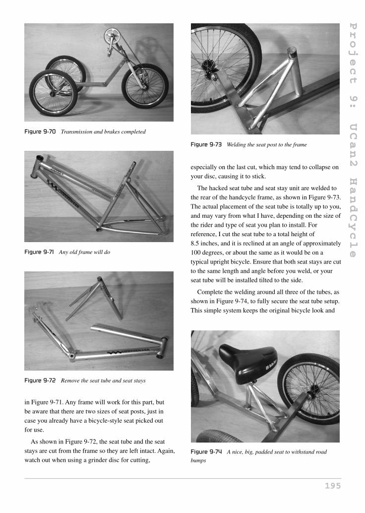
Project
9:
UCan2
HandCycle
Figure 9-70 Transmission and brakes completed
Figure 9-71 Any old frame will do
Figure 9-72 Remove the seat tube and seat stays
in Figure 9-71. Any frame will work for this part, but
be aware that there are two sizes of seat posts, just in
case you already have a bicycle-style seat picked out
for use.
As shown in Figure 9-72, the seat tube and the seat
stays are cut from the frame so they are left intact. Again,
watch out when using a grinder disc for cutting,
Figure 9-73 Welding the seat post to the frame
especially on the last cut, which may tend to collapse on
your disc, causing it to stick.
The hacked seat tube and seat stay unit are welded to
the rear of the handcycle frame, as shown in Figure 9-73.
The actual placement of the seat tube is totally up to you,
and may vary from what I have, depending on the size of
the rider and type of seat you plan to install. For
reference, I cut the seat tube to a total height of
8.5 inches, and it is reclined at an angle of approximately
100 degrees, or about the same as it would be on a
typical upright bicycle. Ensure that both seat stays are cut
to the same length and angle before you weld, or your
seat tube will be installed tilted to the side.
Complete the welding around all three of the tubes, as
shown in Figure 9-74, to fully secure the seat tube setup.
This simple system keeps the original bicycle look and
Figure 9-74 A nice, big, padded seat to withstand road
bumps
195

Project
9:
UCan2
HandCycle
allows a great deal of seat adjustment. It is also very easy
to adapt the top of the seat post and rear of the frame for
a large wheelchair-style seat if you need such a setup.
A fishing boat seat and some kind of belt make a nice
lightweight and sturdy alternative to a wheelchair seat
that can be easily adapted to this setup using a little
imagination and some scrap tubing.
Since the handcycle pilot may have limited or no leg
use, the trike needs a method of keeping the feet secure
as the unit is in motion. A few straight tubes welded to
the front of the frame would do the trick, but this makes
an ugly footrest and could become a hazard due to the
sharp protruding ends of each tube. You can expect that
the rider will eventually bump into something, or try to
squeeze the handcycle through a space too narrow
to fit into, so some type of sturdy rounded footrest should
be considered. As shown in Figure 9-75, a few good
candidates for a set of nicely rounded and sturdy
footrests could be made from a pair of curved bicycle
handlebars.
The placement of the footrest tubing is again a function
of your rider’s needs but, typically, a length of 10 inches
for each footrest would be a decent start. As shown in
Figure 9-76, I cut the old mountain bike handlebars in
half and then cut an angle at each end that would place
the rider’s feet slightly below and in front of the middle
frame tube. The rider’s feet should not interfere with the
front wheel when turning, and the rounded part of the
footrest tubing should be placed in a position that will
not snag on any objects that may rub past them.
These simple footrest tubes can easily be adapted for
foot straps if needed using a pair of belts with buckles,
Velcro strips, a pair of loose bungee cords, or even some
straps made from old laptop carrying straps. As shown in
Figure 9-75 Possible leg mount tubing ideas
Figure 9-76 Leg mounting tubes cut to the same angle
Figure 9-77 Leg mount tubes tack welded in place
Figure 9-77, you will weld the foot-rest tubes at the front
of the middle frame tube where it meets the lower part of
the front tube.
The two footrest tubes will need a bit of help to
survive a good smack against any solid object, so a set of
simple gussets are formed using whatever materials you
have lying around, just like the two small gussets at the
rear of the frame were. Thin flat bar, tubing, or even
some leftover bits from the frames you have been cutting
up will do the trick. Figure 9-78 shows the two
8-inch-long bits of half-inch flat bar I used to strengthen
the two footrest tubes. Again, keep an eye out for sharp
edges, and round them off, if necessary.
Although it is my opinion that an unoiled chain is far
superior to an oiled chain (this is largely debated), you
will still want some type of chain guard to keep fingers
and clothing bits from easily getting snagged in the
chain. Some handcycles have huge, fully enclosed chain
guards over the entire top-drive chain ring, and although
196

Project
9:
UCan2
HandCycle
Figure 9-78 Leg mount support gussets
this is certainly effective, it does look a bit gaudy, and
makes it very annoying to pop the chain back in if it
becomes derailed. Some handcycles just use the chain
guard that was connected directly to the actual chain
ring, but this does not stop things from entering the chain
on the drive side. My system is a cross between both
styles of chain guards that will create a minimal-looking
chain guard that is quite effective in keeping things out
of the chain, yet allows easy access to the chain ring in
the event of a derailment.
As shown in Figure 9-79, my chain guard is just a bit
of thin, half-inch-thick flat bar bent into a circle that
approximates the diameter of the chain ring plus a
quarter inch. Again, I used the same 1/8-inch-thick,
half-inch-wide flat bar as used on all the gussets earlier.
The three small bits will form mounting fingers that will
hold the guard directly to the bottom bracket.
Bend the main guard in shape by hand so there is
about a 1/4 inch of distance between the top of the chain
Figure 9-79 Some half-inch flat bar bent around the front
chain ring
Figure 9-80 Three arms will hold the chain guard in place
and the inside of the guard. The three mounting fingers
are then welded at a slight upwards angle, so that they
can be welded to the bottom bracket and will position the
guard ring right over the chain. In Figure 9-80, I welded
the fingers in place at a slight upwards angle, and at this
point they are a bit too long, since I did not know the
exact length to cut them. I will grind them to the correct
length by trial and error so I can get the chain guard
exactly where I want it.
Figure 9-81 shows the completed chain guard welded
directly to the bottom bracket by the three small
mounting fingers. The mounting fingers were ground to
the correct length by trial and error in order to keep the
space between the chain and the guard to a minimum.
This chain guard is very sturdy and resistant to bending.
I often use it as a handle to carry the handcycle around.
The excess rear axle threads can now be trimmed off
flush with the axle bolts, in order to keep the total
handcycle width to a minimum so that it will easily fit
Figure 9-81 A simple, yet strong chain guard
197

Project
9:
UCan2
HandCycle
Figure 9-82 Trim away the outer axle stubs
between standard door frames. As shown in Figure 9-82,
a quick zip with a thin cut-off disc will do a perfect job of
removing the extra axle stub. Once cut, you should paint
the bare exposed metal area so that it does not rust, and
recheck the nuts to make sure they are nice and tight
using the proper cone wrench.
A decent set of “proper” handcycle grips may cost you
as much as you put into the UCan2 so far, so let’s just
make our own set using a pair of commonly available
plastic bicycle pedals. Not only will these homebrew
handcycle grips feel great, but they will take a standard
set of bicycle handgrips perfectly. As shown in
Figure 9-83, simply hacksaw the plastic pedal wings
away from the core, which will leave you with the
perfect sized ergonomically correct plastic handle, ready
to take any rubber handgrip. Not bad for a few bucks!
Figure 9-83 Plastic pedals cut down to the shell
Figure 9-84 Perfect ergonomic handgrips are made
Once you stretch the rubber grips over the plastic
pedal body, you will be left with a perfect, ergonomically
correct handcycle grip, complete with high-quality,
low-friction bearings. As shown in Figure 9-84, the
hourglass shape is perfect for power and a solid grip
when burning up the track on the UCan2 HandCycle.
Don’t forget that there is a right and left side pedal,
and the one on the left has reverse threads. There is an
R or L stamped on the end of the threaded part, in case
you are having trouble getting them reinstalled in the
crank arms.
Now that the UCan2 is completely rideable, the
hardest part of any project is upon you: waiting for paint
to dry! Since most of the frame was made from new
tubing with the exception of the seat mounting tubing
and front forks, a very light sanding with a few sheets of
emery cloth was all that it took to get the metal ready for
a coat of primer and paint.
I don’t have a powder coating station, nor do I have
any place in my garage to paint, so I simply hang my
frames from an outdoor clothes line and go to town
with a few cans of spray paint. If you take your time
and follow the instructions on the can, a remarkably
good paint job can be accomplished from a few cans of
spray paint (see Figure 9-85). It is true that spray paint
will scratch easier than auto paint, but to look at the
final paint job, you would not be able to tell the
difference.
When the paint is dry and cured, reassemble the
handcycle and repack all the bearings with fresh grease.
You may also want to install some grip tape on the
footrest tubing, and the rear of the frame where
passengers are very likely to hitch a ride. How about a
198

Project
9:
UCan2
HandCycle
Figure 9-85 A good paint job makes your ride look sweet
Figure 9-86 The UCan2 can turn a very small circle
horn, or some cool flame stickers? Accessorize!
Figure 9-86 shows my fully assembled UCan2, about to
get some grip tape and a few cool stickers. Notice the
small, black, plastic plugs placed at the ends of the
footrest tubes. It’s always a good idea to plug all
open-ended tube to keep moisture and critters out of your
frame and to remove all sharp edges.
Well, what are you waiting for—get over to that skate
park and see what this little beast will do! At first, your
handcycle pilot may find getting started a bit awkward,
but after an hour or so, the trike will feel fast, stable, and
get moving with the flick of a wrist. The UCan2 makes
the rider work muscles that normally don’t get much
action, so as time goes on, top speed and climbing ability
will also increase. Oh, and don’t forget to practise using
Figure 9-87 The first test ride
Figure 9-88 The UCan2 laughs at this kind of abuse!
the brakes; we all have to slow down once in a while!
Figure 9-87 shows the mighty Brittany blasting those
upper-body muscles on the UCan2.
Sure, we can give you a lift—try this on your spindly,
pedal-powered wheelchair, pal! The UCan2 will handle
as much weight as you can sensibly pack onto it, as long
as your passenger can handle the extremely fun G-forces
on every corner. As shown in Figure 9-88, I am getting
one serious upper-body workout as I race towards a nice
steep hill to see how agile my passenger really is. For the
record, it is the passenger who really needs the helmet
(sorry for running you over, Brittany)! So there you have
it—the UCan2 freestyle handcycle looking cool and
ready to tackle any terrain that its two-wheeled relative
can. This handcycle is fast, agile, and extremely durable
and looks like it wants to be ridden, not like it has to be
ridden. Not bad for a couple of weekends of work and a
handful of standard bicycle parts!
199

Project
10:
SkyStyle
Tallbike
Project 10: SkyStyle Tallbike
Now what would an Evil Genius vehicle book be without
a tallbike? A tallbike gives you the sensation that you are
hang gliding without a hang glider! You get to face your
fear of heights, confuse your onlookers, and peer into the
neighbor’s second storey window all at the same time!
I have been a fan of tallbikes ever since I figured out how
to hack bicycles, and have even had some tallbike fame
by getting my photo in the 2005 gold edition of the
Guinness Book of World Records. Yep, that dude on page
134 slinging the Canadian flag would be me—cool bike,
eh? Anyhow, you have not earned your bicycle hacking
stripes until you have ridden a tallbike, so let’s get
building.
This tallbike is called the SkyStyle because it is based
on a freestyle BMX bike, and would be perfect for
jousting competitions and many other foolish tallbike
tricks. The overall height is high enough that you have a
good time defying gravity, yet not so high that you can’t
mount the bike without a ladder. Because we will keep
the wheelbase the same as the original BMX bike, you
can play fair at jousting competitions, pull wheelies if
you dare, and many of the “flatland” stunts you might try
on an earthbound BMX. For starters, you will need to dig
in the back of your tool shed for that 1980s BMX that
your mom bought you after you watched Eliot fly
through the air with E.T. in the basket. Actually, any
BMX bike with 20-inch wheels will do the trick, just
like the one shown in Figure 10-1, before getting
the axe.
Figure 10-1 The donor bike ready to be chopped
Figure 10-2 The parts ready for hacking
You need two decent 20-inch wheels, a sturdy frame,
front forks, and all the crank set hardware in order to
make the tallbike. Figure 10-2 shows all the parts
disassembled, cleaned, and ready for severe modification.
The overall height of your final tallbike will depend on
the length of the head tube plus the diameter of the front
wheel. Since this tallbike is designed so that you can step
up from the ground using foot pegs, you will want to
keep the total height from the handlebars to the ground at
reaching distance. The total height of my tallbike from
the ground to the handlebars is approximately 7 feet, so
the head tube was made to a length of about 5 and a half
feet (7 feet minus the height of the front wheel to the top
of the fork hardware). You will need to find a tube with
200Copyright © 2008 by The McGraw-Hill Companies, Inc. Click here for terms of use.

Project
10:
SkyStyle
Tallbike
Figure 10-3 Making the ultra-long head tube
Figure 10-4 Extending the fork stem to match
about the same inside diameter as the original head tube
so that the bearing cups will fit inside, as shown in
Figure 10-3. A piece of electrical conduit or fence tubing
may be just the thing you need.
Once you have chosen an overall tallbike height and
cut the tube to make the head tube, you will have to cut
and extend the fork stem to match the new head tube.
Start by cutting the fork stem in the middle of its length,
as shown in Figure 10-4. A tube cutter does a nice job
here if you have one.
To calculate the correct fork stem extension length,
install the baring hardware, as shown in Figure 10-5, then
lay the cups along the extended head tube so you can
measure the missing section of fork stem. This will help
ensure that all the fork hardware fits correctly once you
have extended the fork stem to match the new head tube.
To extend the fork stem, find some tubing that is fairly
close to the diameter of the fork stem, cut it to the
required length, and then weld the parts together.
Figure 10-6 shows the extension tubing I have found to
make my fork stem longer. This tubing was cut from an
Figure 10-5 Figuring out the extension length
Figure 10-6 Extending the fork stem
old barbell, which had the exact diameter of the fork
stem tubing.
Make the fork stem extension welds as strong as you
can, ensuring that there are no cracks or holes.
Remember, if these welds let go, you are going to learn
the meaning of free fall as you make an instant flight
towards the pavement! Figure 10-7 shows the completed
weld on one end of the extending fork stem. Also, ensure
that the bearing cups fit over the weld, and only grind as
much material as necessary if there is a little too much
weld buildup around the joint.
Figure 10-7 Welding the fork stem extension
201

Project
10:
SkyStyle
Tallbike
Figure 10-8 Completed fork set and head tube
When you are done extending the head tube and
fork stem, the two parts should fit back together just like
they did on the original bicycle they were taken from.
Figure 10-8 shows the completed fork set and head
tube with all bearing hardware installed. The forks
should turn freely and without friction once everything is
installed.
Now that your extended head tube is completed, you
need to hack away the original head tube from the BMX
frame so you can replace it with the new one. As shown
in Figure 10-9, make the cuts as close to the head tube as
possible to keep the frame tubing as long as possible.
You don’t want to shorten the wheelbase any more than
necessary, or you will be doing wheelies all the time!
You could also slice the head tube in half lengthwise and
weld it directly to the new head tube if you wanted to.
The new extended head tube will be installed onto the
BMX frame, as shown in Figure 10-10, just like the
original head tube once was. The one thing to keep in
mind is head tube angle versus handlebar-to-seat
distance. As you add more head tube angle, you make the
Figure 10-9 Removing the original head tube
Figure 10-10 Installing the new tall head tube
distance between the seat post and handlebars decrease,
so you will have to find an angle that gives you the best
of both worlds. Draw an imaginary line straight up from
the original seat post tube, and then try to install your
new head tube so that the distance between this
imaginary line and the top of the head tube is no less than
half of what it is at the bottom of the frame. Dude, does
that make sense to you? If not, let me explain it another
way. If the distance between the original seat post and
head tube of the BMX frame was 28 inches, then the
distance from the top of the new head tube to the new
seat post should not be less than 14 inches.
The seat tube must now be extended upwards
vertically as high as the top of the new head tube, as
shown in Figure 10-11. Any length of 1 inch or 1.25 inch
tubing will do. I used a bit of electrical conduit that was
lying around the shop. The new seat tube should extend
upwards from the frame at an almost vertical angle,
keeping in mind that the more it leans back, the easier it
will be to wheelie your tallbike. Maybe you want this
instability for a jousting tournament? For the best
stability, try to plant your butt ahead of the front wheel,
not over the top of it.
The new top tube is installed between the top of the
new head tube and seat tube, as shown in Figure 10-12.
The length of this tube is determined by the angle of your
head tube and seat tube, and it should be at least
16 inches long if you plan to ride this bike without
having your knees banging off the handlebars. I just
found an old tube hacked from some other frame that
was used for another evil vehicle. Recycle, reuse!
202

Project
10:
SkyStyle
Tallbike
Figure 10-11 Installing the long seat tube
Figure 10-12 Adding the new top tube
Your tallbike is almost ready, but the frame will need
some reinforcement if it is to withstand the crashes that
will surely be coming in the near future. With only the
head tube and seat tube extending the frame, the ride
would be seriously wobbly, and the frame would easily
warp if you were to mow into a curb or smack head on
into “Sir Bleedsalot’s” tallbike during the jousting finals.
Figure 10-13 Adding some strength to the frame
By adding a simple truss into the open frame, you create
a triangle, which will make the frame many times more
rigid and stable. This tube can be any appropriate length
of 1 inch or even ¾ tubing, and it is installed as shown in
Figure 10-13.
To step up to the cranks during a mounting procedure,
you will need a lower set of foot pegs unless you have
abnormally long legs. You can purchase some nice foot
pegs at the bike store and weld a bolt to the frame to hold
them, or build the poor man’s foot pegs, as shown in
Figure 10-14, from some scrap tubing and a few washers.
The washers are a safety precaution that will save your
hide from impalement during one of those wonderful
moments when you are lying on the road and your
tallbike is falling over on you. Oh yes, you will
understand this one day, I promise!
As shown in Figure 10-15, the washers are welded and
then ground smooth so there is no sharp edge to your foot
pegs. Sharp edges are not a good thing on a tall bike,
especially one designed for battle.
Figure 10-14 Poor man’s foot pegs
203

Project
10:
SkyStyle
Tallbike
Figure 10-15 Completed foot pegs
Figure 10-16 Foot peg position
The lower foot pegs are installed on the lower part
of the extended seat tube, as shown in Figure 10-16.
This position makes it “easy” to step up to the
pedals as you launch the tallbike from a standing start.
If you plan on being a total maniac of the sky, then add
more pairs of foot pegs all over the bike, so you can
astound your buddies on the ground with your fancy
footwork.
You will need to hack a bottom bracket from another
frame in order to install the cranks onto your tallbike.
The best way to do this is to cut it from the donor frame
so an inch or so of the original tubing is still there, as
shown in Figure 10-17. This way, you can simply weld
the tubing stubs directly to the new frame.
The new bottom bracket is installed in an appropriate
place on the new seat tube, as shown in Figure 10-18.
Where you put the bottom bracket will depend on how
long your legs are (your inseam), but you could simply
measure this from a bicycle that fits you.
If you get lucky, the distance between your crank set
and rear wheel sprocket will be just perfect so that you
Figure 10-17 Adding the bottom bracket
Figure 10-18 Installing the bottom bracket
can join together your new chain and have it nice and
tight. You can move the rear wheel slightly in the
dropouts to pick up some of the tension, but there is a
chance that your chain might be way too slack once
it is made. A chain tensioner is needed when you add one
more link and your chain is too long, or if you
remove a link and the chain is too damn short. Any
half-inch V-belt idler pulley can be used to pick up the
chain slack by simply welding it in the correct place
somewhere on the frame. An example pulley is shown in
Figure 10-19.
Figure 10-20 shows how the idler pulley can be
used to pick up any chain slack that cannot be taken up
by simply moving the rear wheel in the dropouts. Join
your chain until you have as many links as necessary,
204

Project
10:
SkyStyle
Tallbike
Figure 10-19 You may need a chain tensioner
Figure 10-20 Installing the chain tensioner
and then hold the pulley somewhere on the frame so
you can mark the best place to weld the bolt that
holds it there. A tallbike chain should be fairly tight,
as a derailment will mean a dismount—an ugly
dismount if the chain happens to get tangled in the rear
wheel!
Figure 10-21 shows the finished SkyStyle tallbike,
complete with a sloppy, black, battle-ready paintjob.
Hey, why worry about paint quality on a bike that is
certain to end up in a tangled mess at least a dozen times
during a jousting competition? The thick clothing helps
me avoid road rash, as well as the harsh subzero climate
of northern Ontario!
Mounting the SkyStyle tallbike is a process that is
easily learned. As shown in Figure 10-22, step one
involves gripping the handlebar with one hand as you
kick off from the ground to get the bike rolling, while
one foot is on the lower foot peg. It may seem odd to
steer a bike by reaching 7 feet into the air, but if a
Figure 10-21 Dude, let’s ride!
Figure 10-22 Step one of the launch procedure
monkey can learn to ride a unicycle, then you certainly
have no excuse!
As shown in Figure 10-23, step two of the launch
procedure is a little more precarious. At this point, you
must not only steer the tallbike from one side as it leans,
but also climb from the lower foot peg up to the pedal on
the opposite side of the bike. Hopefully, you had the
pedals in the correct position before you started. Oh, did
I forget to mention that? Oops! Now you know.
205

Project
10:
SkyStyle
Tallbike
Figure 10-23 Step two of the launch procedure
If you are actually standing on one of the pedals with
both hands on the handlebars, as shown in Figure 10-24,
then you are past the hardest part of the launch procedure
and home free. If your launch has not gone well
according to plan, then you are lying on your back on one
side of the street, with your tallbike on the other side of
the street, as the neighbors point you out to their kids
through their picture window. “Now, Billy, this is why
I won’t let you play with that Graham boy—he is a bad
example.” You know the routine by now. Well, we hope
you have fun with your SkyStyle tallbike. Watch out for
low-hanging power lines, and remember to put your
hands out in front of you on the way down during battle!
Figure 10-25 shows the SkyStyle pilot out for a leisurely
ride, free of ankle-biting dog attacks, and highly visible
in traffic. Oh, and yes the tallbike does have brakes; they
are built into the rear wheel in the form of a coaster brake
which engages when you pedal in reverse. Have fun, and
respect the laws of gravity!
Figure 10-24 Step three of the launch procedure
Figure 10-25 Off to battle we go!
Next up, an entire section devoted to electric vehicles,
from a cool mini bike to an electric trike suited to the
younger crowd.
206

Section 5
Electric Power
207Copyright © 2008 by The McGraw-Hill Companies, Inc. Click here for terms of use.

Project
11:
Sparky
Minibike
Project 11: Sparky Minibike
The goal of this project is to arm you with the necessary
information and skills to create your own fun electric
vehicle (EV) from scratch. There are many inexpensive
electric scooters and pocket bikes available, but let me
assure you that the acceleration, hill climbing ability, top
speed and overall durability of these units cannot match
the quality of a home-built unit such as Sparky.
Of course, these traits are dependent on your choice of
drive motor, batteries and overall gear ratios, but even
with a small investment in time and money, you will be
able to build a one of a kind EV that can climb hills with
ease, operate for well over an hour on a single battery
charge, accelerate with enthusiasm, and be able to
take on most terrain without falling apart. Unlike
petrol-burning mini bikes, the electric motor and
transmission system used in Sparky are so quiet that the
only sound made by the unit is the sound of the wheels
hitting the pavement, even at full speed. This silent
operation allows the unit to be ridden practically
anywhere without polluting the area with noise. Your
neighbors and the general public will likely not be
annoyed with this type of quiet EV.
Unlike many of our do-it-yourself plans, this project
does not require a rigid set of materials and
measurements, since the goal is to build the electric
vehicle to your standards using the parts you have
available. Sure, you could build an exact replica of
Sparky by following the instructions, but with the great
availability of various small electric motors, batteries and
wheels, why limit yourself to a single design? You may
want to build a smaller EV for youngsters to ride at
camp, convert an old gas mini bike to electric for hunting
or trail riding, or go all the way and build a fully street
legal motorcycle—this is all possible by choosing the
appropriate parts. When I built Sparky, my goal was to
pack as much power, range, and ruggedness as I could
into the smallest possible size, and with a top speed of
approximately 31 mph (50 km/h), streetbike-like
acceleration, and a full hour run time on a charge. To add
icing to the cake, I accessorized Sparky to resemble a
pint-sized Harley fat boy, complete with tree-trunk front
forks, large fenders, and an old-school-style seat.
Electric motors have nothing in common with their
gas-powered counterparts, even though they both may be
rated in horsepower (HP) and rotations per minute
(RPM). At only 2.5 HP, the coffee-can-sized motor used
on Sparky will generally outperform a 5 HP gas engine
(commonly used on go-carts), especially during
acceleration. Motor controllers are another alien
technology, especially if you have worked on
gas-powered vehicles before, but don’t worry, it will all
be explained in this section, which is why the best way to
approach this plan is by reading the entire text all the
way through in order to understand the technologies
used, and to see why I choose the parts used to build
Sparky. Once you understand the core technologies and
components needed, you can build a small electric mini
bike just like Sparky, or create your very own custom
electric monster from scratch.
The batteries like the ones shown in Figure 11-1 are
probably the most important component in any electric
vehicle, large or small. If your batteries cannot deliver
Figure 11-1 Two 12-volt GEL batteries
208Copyright © 2008 by The McGraw-Hill Companies, Inc. Click here for terms of use.

Project
11:
Sparky
Minibike
the needed amperage, then it really does not matter how
powerful your drive motor is. One should not compare
battery size to gas tank capacity on a gas-powered
vehicle, since a teaspoon of fuel will run a gas-powered
engine at full power, even if for a limited amount of time,
whereas a tiny battery will simply fail to turn an electric
motor at all. Batteries are rated in voltage and amp hours,
and these two variables will determine how fast your
motor will turn, how much horsepower it will deliver
(more on this later), and for how long. OK, get out your
pocket protector; things are going to enter the “nerd
zone” for a while!
Although the “fuel” for an electric motor is a function
of the amperage and voltage of a battery, there is no way
of comparing this to a simple tank of gas. If I had to
guess, then I would estimate that amperage is the
quantity of fuel per hour delivered to a gas engine, and
the voltage is the octane, or burn quality, of the gas. The
more amperage a battery can deliver, the more torque the
motor shaft will deliver, and the more voltage this
amperage is delivered with, the faster the motor shaft
will spin. Although this is an oversimplified explanation,
it does hold true for many of the small electric DC
motors you will have to choose from when sourcing parts
for your mini bike. Before you can choose a motor, or the
appropriate batteries, you should know the basic facts
and formulas dealing with amps, watts, volts, and
horsepower.
Watts
Most small, electric, direct current (DC) motors are rated
in watts, and wattage is derived by multiplying voltage
by amperage (volts × amps). So, if a motor claims that it
will deliver 900 watts at 36 volts, then you know it will
take 25 amps from your battery pack (900 watts divided
by 36 volts). This simple formula works, as long as you
know any two pieces of the watts, volts and amps puzzle.
Remember that 250-watt light bulb in your garage? Sure,
just divide 250 watts by 120 volts, and you will then
know that your light bulb needs just over 2 amps to
operate. The wattage ratings of a DC motor is the most
important of all ratings, and this value will determine the
size and type of battery and motor controller needed, as
well as the overall performance of the vehicle. The motor
I used on Sparky is rated at 2000 watts continuous.
Horsepower
This rating isn’t really very useful in the electric motor
world, since an electric motor’s horsepower is rated at
zero RPM under load, whereas a gas engine’s
horsepower is rated at its maximum RPM under no load.
What this means is that an electric motor rated at the
same horsepower as a gas engine will put the gas engine
to shame when it comes to acceleration and torque.
To make things even more confusing, gas-powered
engines are rated at their peak horsepower, while electric
motors are rated at their continuous rated horsepower.
The peak horsepower of an electric motor is usually
8 or 10 times its continuous rating, so this makes an
electric motor of an equal horsepower seem all the more
powerful. If you really want to rate your motor in
horsepower, or find one that is rated in this way, then you
can convert by using the ratio of 1 horsepower equals
approximately 746 watts. To compare this to a gas
engine, I like to assume that a 1-horsepower electric
motor will feel like a 3-horsepower gas engine. The
motor used on Sparky is 2000 watts, so this works out at
2.68 horsepower (2000 watts/746), which should seem
like a gas engine of approximately 8 horsepower.
Amperage ratings
Battery amperage may be stated in various ways
depending on the intended use for that particular battery.
You will see things like CCA (cold cranking amps),
MCA (marine cranking amps), RC (reserve capacity),
and AH (amp hours). It is the last rating, AH (amp
hours), that we are really interested in because this is the
maximum energy that can be delivered from the battery
every hour. By knowing the power rating of the motor,
we can figure out the minimum run time for your vehicle
before it needs a recharge. I say minimum run time
because your motor will not always need maximum
amperage, and if you are not climbing large hills, or
driving like a stunt person all of the time, you may only
be using a small percentage of the motor’s rated current.
Using a few of the above formulas on Sparky’s
2000-watt motor, I can determine that it will draw a
maximum of 83.33 amps at its rated 24 volts (2000 watts
24 volts), and since my battery pack can deliver 32 amp
209

Project
11:
Sparky
Minibike
hours, I would expect a run time of only .38 hours, or
about 20 minutes (32 AH/83.33 amps). This assumes that
I am forcing the motor to work at its full rated capacity at
all times, and this is never the case; in reality, I typically
get 1.5 hours or more between charges, even when
spinning up dirt and pulling wheelies. A realistic measure
of run time between charges will be something you will
have to find out from actual use, as it will certainly vary.
Voltage
Each battery has a rated voltage, with 12 volts being the
most common for batteries typically needed for small
electric vehicles. Since most small electric motors run at
voltages between 24 and 48 volts, you will have to
connect two or more batteries in series to achieve the
required voltage rating for the battery pack. A series
connection means that the positive terminal of battery #1
connects to the negative terminal of battery #2, and
power is taken from the free terminal of each battery
(one positive, and one negative). In series, a battery
cannot deliver any more amp hours than the rated
capacity of a single battery, but it does double the
wattage available because it also doubles the voltage. My
two batteries shown in Figure 11-1 are rated at 12 volts,
and 32 amp hours each, so in series they deliver 32 amp
hours at 24 volts, or 768 watts (24 volts × 32 amps).
A single battery would only deliver 384 watts (12 volts ×32 amps). If wired in parallel (not recommended), the
batteries would double their amp hours to 64, but the
voltage would remain at 12 volts, so they would again
deliver 768 watts (12 volts × 64 amps). Parallel wiring
of batteries should never be done, since one battery may
try to charge the other if they are not equal, which could
result in damage, heat, or fire. To sum this up, you will
need to connect as many 12-volt batteries in series as
necessary, in order to achieve the desired voltage, but
your overall amp hour capacity will be the same as one
single battery can deliver.
Battery type
Not all 12-volt batteries are the same, and this fact is
largely reflected in the price. Typical car batteries are not
well-suited for electric vehicle use, even though their
price may be inviting. A car battery is made to deliver an
enormous amount of power in a very short time and then
become fully charged shortly after. As many of us know,
a car battery will be destroyed if run completely down
more than a few times in a row, which is why it will not
be a very good candidate for our purpose. Car batteries
are also very messy, require some fluid maintenance, and
do not like vibration or uneven mounting. A much better
choice for your battery needs is the non-spillable, sealed,
GEL deep cycle battery. These batteries have no
removable tops since they contain no liquid (it is in a
gelled state)—they can be mounted in every orientation
except upside down, they can withstand moderate
vibration, and they can be depleted completely many
times without damage. These batteries are commonly
rated as marine or wheelchair-use batteries, and the
smaller units may be rated for security or battery backup
use. They are more expensive than conventional car
batteries, but will outlast them many times over,
especially in our electric vehicle. Multiple batteries
should always be the same type, and approximately the
same age, especially when charging them together as a
24 or higher voltage pack.
Charger
The best way to charge your batteries is together as a
single pack, so if your battery pack voltage is 24 volts,
you will need a 24-volt charger. These are readily
available, and often you can find older ones at
secondhand stores, or from shops that repair or sell
wheelchair parts. A common 12-volt charger used for a
car battery will also work, but you will either have to
charge one battery at a time (very slow), or purchase two
chargers and run them both, one on each battery.
Whichever you choose, the charger should be fully
automatic, shutting off when the battery is at peak
capacity in order to avoid damage from overcharging.
Only the worst chargers available will not have a current
meter or automatic shutoff, and these should be avoided.
Also, make sure that the charger you have is rated for the
type of battery you are using, such as wet lead acid, or
sealed gel.
I hope that wasn’t too much nerd jargon in such a
small space! It really does help to know what to expect
from batteries and motors before you start searching for
210

Project
11:
Sparky
Minibike
parts, and the above information is the basic lingo you
will have to know when searching the numerous sources
for motors and batteries for your vehicle. I still
recommend that you read this entire plan before sourcing
any parts, as there are more tips and facts further ahead
that will help you beat the pitfalls of part sourcing, and
avoid many common mistakes while hunting for parts.
As the build progresses, each major component will be
described in more detail. Hey, buddy, put that furnace
motor down and read the rest! It wouldn’t work for this
project anyhow, trust me.
Once you have read through the entire plan, and
started from the beginning, you will probably have
chosen a motor and the appropriate batteries to achieve
the desired acceleration and run time for your mini bike.
The batteries make up the bulk of the weight and size, so
we will start by building a strong cage or battery box to
hold them together as a single unit. A battery box can be
easily removed from the rest of the frame for charging,
transporting the mini bike, and allowing you to have
multiple packs for continuous non-stop fun. A nice
battery box can be made by forming a base, like the one
shown in Figure 11-2, from some 1-inch, 1/16-inch-thick
angle iron. You will want to cut the pieces, as shown in
Figure 11-2, so that the battery sits into the base of the
box, but not too tight that it becomes stuck. The inside
measurement of the box should be at least 1/8-inch larger
than the battery.
The four pieces of angle iron that make up the battery
box base are shown in Figure 11-3, tack welded together
at the corners. The angle iron could have also been
formed by cutting the ends at 45 degrees, but I find this
way to be a bit more tolerant of small errors that could
make the box too small for the batteries to slide in
easily. With only the corners tack welded together, it
Figure 11-2 The base for the battery box
Figure 11-3 Welding the battery box base pieces
is easy to force the box into a square by tapping it with a
hammer.
Before you completely weld the battery box base
together, test fit one of your batteries to make sure that it
is snug, but is not wedged in too tight. As shown in
Figure 11-4, my 32-amp-hour GEL battery drops right
into the base with approximately 1/8-inch clearance
between the battery edges and the angle iron. Once
tested, you can weld the outside corner and underside of
all joints to complete the base of the battery box. Do not
weld the inside joints, or your battery may not fit. For
reference, my battery measures 7.75 by 6.5 inches, and is
6 inches tall to the top of the terminals.
As stated earlier, my battery pack will be made from
two series-connected, 32-amp-hour, deep-cycle,
Figure 11-4 Testing the battery fit
211

Project
11:
Sparky
Minibike
GEL-type batteries at 12 volts each. The resulting battery
pack will be able to deliver 32 amps at 24 volts for one
hour, or any ratio of 32:1 up to the battery’s maximum
discharge ability, for example, 64 amps for 30 minutes,
or 16 amps for two hours. The current draw from the
motor during typical riding will vary quite a bit, with
acceleration from a dead stop requiring the most current,
and cruising on the flats without any headwind requiring
very little current. Your ultimate acceleration will depend
on your battery pack’s maximum current discharge, and
the maximum current that will flow through your motor
controller if you decide to use one.
On a small electric vehicle like Sparky, the maximum
discharge of most deep cycle batteries will be more than
enough for powerful acceleration, bordering on the
wheelie zone, but don’t expect to throw on a huge
amp-hungry motor and a pair of tiny batteries and have
them deliver 900 amps in one minute just because they
can deliver 15 amps in one hour—there is a limit. If you
really want to know what the maximum discharge
capacity for your battery is, then you will probably have
to spend some time digging around on the
manufacturer’s website.
The sides of the battery box are made from the same
1-inch angle iron as the base, and are welded at each
corner to continue the box upward along the corners of
both batteries, as shown in Figure 11-5. The top of the
box should be at least half an inch higher than the top of
the battery terminal to protect the terminals from the rest
of the frame. I made these four side pieces 14 inches in
length for my battery pack. The four side pieces are first
tack welded in place, so that you can do another test fit
with the batteries before welding the outside of the joints.
There should be a bit of wood or rigid foam between the
two batteries, so that the top battery is not resting directly
on top of the lower battery’s terminal, as excessive
vibration may damage the top battery. Do not attempt to
make any welds with the batteries installed or they
will melt!
The top of the battery box is made by welding flat bar
of the same thickness as the angle iron across the top, as
shown in Figure 11-6, so that it completes the box.
Flat bar is needed since angle iron would make it
impossible to install the batteries due to the lip it creates.
If you do not have any scrap bits of flat bar to use, you
can cut the angle iron along the edge with a grinder disc
to make two pieces of flat bar from it. Again, it’s a good
Figure 11-5 Installing the battery box sides
Figure 11-6 Finishing the battery box
idea to tack weld and test fit before committing any
welds, just in case you need to make a few adjustments.
Once everything is looking good, make the final welds
and clean up the joints with a sanding disc, as shown in
Figure 11-6, to complete the battery box.
Once you have the battery box completed and have
chosen a drive motor (or at least know the measurements
212

Project
11:
Sparky
Minibike
of the drive motor), you can begin working on the frame.
My goal was to build the smallest frame possible around
my battery pack, drive motor and motor controller
without an inch to spare. I thought it would be fun to
have a cute-looking “mini hog” that would look as
though it was a kids’ toy, but have more than enough
power to leave any department store scooter or pocket
bike whimpering in the dust during a race.
My original electric mini bike had a frame made of
square tubing, but this time I wanted a little more style,
so I decided to go with a nice curved “spine” over the top
that would define the general proportions of the rest of
the frame. To achieve this without a pipe bender, I
bought two 1.5-inch thin walled electrical conduit (EMT)
elbows from a hardware store. In Figure 11-7, I marked
the area of each elbow that I planned to cut, in order to
weld them together to form the appropriate sized spine
for my frame. If for some reason you cannot find EMT
where you live, then any 1/16-inch walled mild steel
tubing (even square) would work. You could even
butcher a mountain bike frame for the large tubing used
in the frame.
Feel free to experiment with your own frame designs.
As long as you build the frame around your key
components in such a way that everything fits together,
and so that your belt or chain will have adequate
clearance, your imagination can run wild. As you read
on, you will see why I chose the size and style of
materials I did, but you could use the same techniques to
create a variation of Sparky, a full-size motorcycle, a
chopper, or even a four-wheel go-cart if you wanted to.
Since I was going to build the frame spine over the
main components, then build the rest of the frame around
Figure 11-7 A pair of 1.5-inch conduit elbows
this configuration, I only tack welded the two elbows
together at this point, just in case I decided to cut them
shorter. As shown in Figure 11-8, there would be plenty
of length for the battery box, drive motor and rear wheel
under this smooth-flowing spine. It’s always easier to cut
the excess away after you have a plan, rather than being
stuck with a piece that’s too short.
Figure 11-9 shows visually how I attack a frame when
I have no plan, but do have most of the components.
Since the battery box would require the most space, and
dictate the overall height of the frame, it was important to
finish it first so that the other components could be
placed around it. My goal was to pack as much “stuff”
into the smallest area possible, so it was very important
to lay out the frame like this, just in case something
unexpected came up. The space between the battery box
and the rear wheel is the amount of space the motor will
occupy, and although my motor was still on order from
the supplier at the time, I had detailed drawings, and
knew the exact size and shape. With the motor installed
directly between the rear wheel and the battery box, there
would be just enough room above the motor for either a
large motor controller, or an automotive solenoid,
depending on which way you plan to control the current
Figure 11-8 Elbows tack welded together
Figure 11-9 Visualizing the frame layout
213
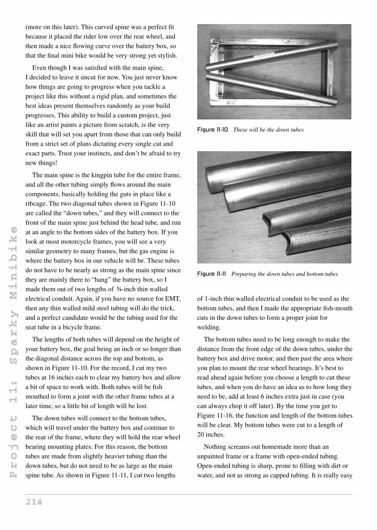
Project
11:
Sparky
Minibike
(more on this later). This curved spine was a perfect fit
because it placed the rider low over the rear wheel, and
then made a nice flowing curve over the battery box, so
that the final mini bike would be very strong yet stylish.
Even though I was satisfied with the main spine,
I decided to leave it uncut for now. You just never know
how things are going to progress when you tackle a
project like this without a rigid plan, and sometimes the
best ideas present themselves randomly as your build
progresses. This ability to build a custom project, just
like an artist paints a picture from scratch, is the very
skill that will set you apart from those that can only build
from a strict set of plans dictating every single cut and
exact parts. Trust your instincts, and don’t be afraid to try
new things!
The main spine is the kingpin tube for the entire frame,
and all the other tubing simply flows around the main
components, basically holding the guts in place like a
ribcage. The two diagonal tubes shown in Figure 11-10
are called the “down tubes,” and they will connect to the
front of the main spine just behind the head tube, and run
at an angle to the bottom sides of the battery box. If you
look at most motorcycle frames, you will see a very
similar geometry to many frames, but the gas engine is
where the battery box in our vehicle will be. These tubes
do not have to be nearly as strong as the main spine since
they are mainly there to “hang” the battery box, so I
made them out of two lengths of ¾-inch thin walled
electrical conduit. Again, if you have no source for EMT,
then any thin walled mild steel tubing will do the trick,
and a perfect candidate would be the tubing used for the
seat tube in a bicycle frame.
The lengths of both tubes will depend on the height of
your battery box, the goal being an inch or so longer than
the diagonal distance across the top and bottom, as
shown in Figure 11-10. For the record, I cut my two
tubes at 16 inches each to clear my battery box and allow
a bit of space to work with. Both tubes will be fish
mouthed to form a joint with the other frame tubes at a
later time, so a little bit of length will be lost.
The down tubes will connect to the bottom tubes,
which will travel under the battery box and continue to
the rear of the frame, where they will hold the rear wheel
bearing mounting plates. For this reason, the bottom
tubes are made from slightly heavier tubing than the
down tubes, but do not need to be as large as the main
spine tube. As shown in Figure 11-11, I cut two lengths
Figure 11-10 These will be the down tubes
Figure 11-11 Preparing the down tubes and bottom tubes
of 1-inch thin walled electrical conduit to be used as the
bottom tubes, and then I made the appropriate fish-mouth
cuts in the down tubes to form a proper joint for
welding.
The bottom tubes need to be long enough to make the
distance from the front edge of the down tubes, under the
battery box and drive motor, and then past the area where
you plan to mount the rear wheel bearings. It’s best to
read ahead again before you choose a length to cut these
tubes, and when you do have an idea as to how long they
need to be, add at least 6 inches extra just in case (you
can always chop it off later). By the time you get to
Figure 11-16, the function and length of the bottom tubes
will be clear. My bottom tubes were cut to a length of
20 inches.
Nothing screams out homemade more than an
unpainted frame or a frame with open-ended tubing.
Open-ended tubing is sharp, prone to filling with dirt or
water, and not as strong as capped tubing. It is really easy
214

Project
11:
Sparky
Minibike
to plug the end of a round tube by simply welding an
appropriate sized washer over the end. As shown in
Figure 11-12, I tack welded a pair of washers over each
end of the bottom tubes. It is much easier to get this done
ahead of time, since you can work with the tubing on
your bench as a single unit. Once welded to the frame, it
will be difficult to get your grinder into position. Get
’er done!
The tubing caps are welded all the way around then
ground down, as shown in Figure 11-13. The completed
product looks very professional, and will resist filling
with debris when you ride, and will not be a source of
danger if for some reason the frame ever came in contact
with somebody. You could also fill the washer holes if
you like, but I decided to leave them as they are, just in
case I want to add a few accessories, such as reflectors or
lights to the frame.
Figure 11-12 Plugging up open tubing ends
Figure 11-13 Washers welded and ground
As stated earlier, the bottom tubes will connect to the
base of the down tubes and travel under the battery box
to the rear of the frame, so they need to be welded, as
shown in Figure 11-14. I chose an angle of 90 degrees so
that the down tubes run directly along the front of the
battery box up to the main spine tube. This allows the
most compact configuration possible, placing the front
wheel very close to the front of the battery box. On many
motorcycle frames, the down tubes travel from the base
of the engine towards the head tube at a slight angle, and
the front wheel has several inches of clearance between
the motor and frame due to the rake of the front forks.
More front fork rake generally means a more stable bike
at higher speeds, but my goal for design was size, and I
did not plan to hit the highways or break any speed
records, so minimal rake would be fine. Again, feel free
to experiment with your own design, and look at other
mini bike and motorcycle frames for ideas. Wouldn’t a
chopper be cool? You know it!
Once the down tubes and bottom tubes are welded
completely around and ground clean, they will be
installed, as shown in Figure 11-15, so that the bottom
tubes continue to the rear of the frame, and the down
tubes travel along the front of the battery box at a
diagonal angle to meet just under the main spine tube.
You may want to clamp the down tubes to the bottom of
the battery box, just so they stay in place while you test
fit the rear wheel and make the other tubes for welding.
You may also want to grind the tops of the down tubes to
form a good joint for welding with the main spine tube,
Figure 11-14 Joining the down tubes and bottom tubes at
90 degrees
215

Project
11:
Sparky
Minibike
Figure 11-15 Laying out the frame tubing
but don’t do this until you visually lay out the rest of the
frame, as will be shown next.
The next weld you make will pretty much dictate the
final shape of the frame, position of the rear wheel and
maximum motor size that you can install into the frame.
As shown in Figure 11-16, it’s important to visually
check your layout before making any final welds, just in
case your drawing or rough plan is not as accurate as you
might have thought. There are some potential problems
that may not be obvious in a drawing. Will the rear wheel
slide out of the frame? Will the inflated tire rub on the
Figure 11-16 Installing one of the truss tubes
bottom tubes with pressure applied? Can the battery box
slide out of the frame easily? Once the rear bearings are
installed, will the rear tire clear the back of the main
spine tube? As you can see, the only way to feel
confident about committing to a final frame design is to
try to answer all of these questions visually.
You should try to set up the mini bike using as many of
the main components as you can, such as the rear wheel,
axle, bearings, and motor before welding the top of the
down tubes to the main spine tube. Don’t forget about
fender, sprocket or pulley clearances, and brake drum
arms if your wheel has one.
Figure 11-17 shows the clearance above the battery
box and main spine tube after tack welding the frame
parts together, based on the visual layout in Figure 11-16.
I ended up with a quarter inch just above the top of the
battery box, which would be plenty of room to allow the
quick removal of the pack for charging or swapping.
Make a few good tack welds between the down tubes and
the spine tube to hold it in place and allow for any
alignment fine tuning. Alignment should be checked from
directly above the frame as well to make sure that both
bottom tubes are parallel to each other, and that the spine
tube runs right down the middle of the bottom tubes.
At this stage, it is easy enough to manipulate the frame to
get it back into alignment, but if it is too far out, you are
better off breaking the tack welds and redoing them. The
best welders are not those who get things perfect on the
first try, but those who fix all their mistakes.
To add a bit of style to the little frame, and make good
use of the mountain bicycle frame to be used for the head
tube, I decided to recycle the fork legs for the last part of
the frame, which I will refer to as the “rear tubes” from
now on. The rear tubes will complete the frame by
Figure 11-17 Tack welding the frame together
216

Project
11:
Sparky
Minibike
fastening the rear of the bottom tubes to the rear of the
main spine tube and allowing a place for the bearing
mounting plates to connect, if your design calls for them.
Although you could have simply used a few lengths of
1-inch or 3/4 EMT for this part of the frame, the fork legs
offer a nice tapered and flowing look to the overall
design that perfectly complements the curve of the main
spine. Remember that building a custom is an art, not a
rigid set of rules!
When cutting fork legs, try to get as close to the stem
as possible without cutting into the stem, because we will
later use that stem to create the triple-tree fork. You can
also cut off the fork dropouts as close to the end as
possible, and add them to your ever growing pile of parts
for some other project. Figure 11-18 shows the legs cut
away from the stem with minimal waste. I make all my
cuts with a 3/32 cut-off grinder disc, but you could also
do this with a hacksaw if you are worried about slicing
into the stem.
As shown in Figure 11-19, the fork legs will form the
rear tubes by completing the main frame. There is no
Figure 11-18 A de-limbed mountain bike front fork
Figure 11-19 Positioning the rear tubes
magic measurement dictating where on the main spine
tube the fork legs should be placed, but it is important
that when welded to the bottom tubes, the axle will end
up in the correct position to allow for adequate clearance
between the motor and rear tire. I have built enough
custom designs from drawings and sketches to know that
you can never fully trust your two-dimensional drawings
for accuracy, especially when working with such a
compact design. The only way to be certain that all the
components will live together in harmony is to lay out
the frame visually again. It is a bit annoying to get out all
the parts and prop them all up again, but this sure beats
the disappointment that you will feel when your only
option is to cut fully welded tubing later (my first-hand
experience).
As shown in Figure 11-19, I decided to place the fork
legs (rear tubes) up as far as length would allow along
the main spine tube, so that it would look like the legs
were flowing directly from the top curve of the frame.
There is adequate clearance between the tire rubber and
the tubing, and enough room for my belt drive to be
installed on the axle without rubbing on any of the
tubing. Things are very close, but by visual inspection, I
expected to have no problems with this design.
Even though the mock layout seemed perfect, I only
tack welded the rear tubes in place, as shown in
Figure 11-20. The tack welds are strong enough to handle
the frame without fear of misalignment, but allow for
easy adjustment or removal if something unexpected
Figure 11-20 Tack welding the frame tubing
217
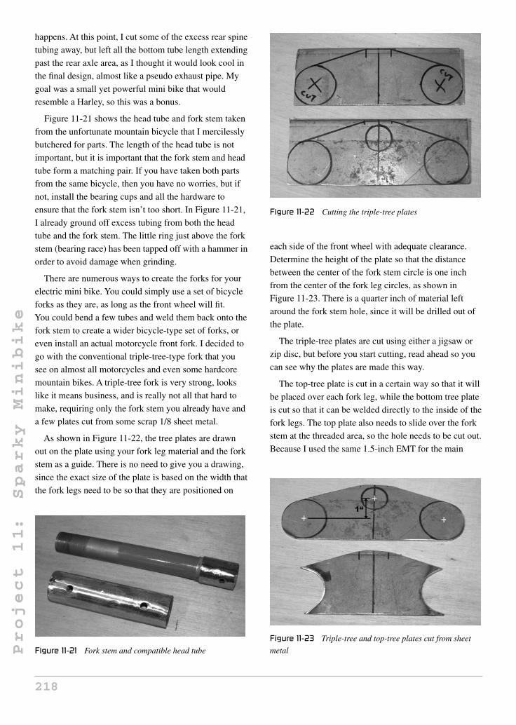
Project
11:
Sparky
Minibike
happens. At this point, I cut some of the excess rear spine
tubing away, but left all the bottom tube length extending
past the rear axle area, as I thought it would look cool in
the final design, almost like a pseudo exhaust pipe. My
goal was a small yet powerful mini bike that would
resemble a Harley, so this was a bonus.
Figure 11-21 shows the head tube and fork stem taken
from the unfortunate mountain bicycle that I mercilessly
butchered for parts. The length of the head tube is not
important, but it is important that the fork stem and head
tube form a matching pair. If you have taken both parts
from the same bicycle, then you have no worries, but if
not, install the bearing cups and all the hardware to
ensure that the fork stem isn’t too short. In Figure 11-21,
I already ground off excess tubing from both the head
tube and the fork stem. The little ring just above the fork
stem (bearing race) has been tapped off with a hammer in
order to avoid damage when grinding.
There are numerous ways to create the forks for your
electric mini bike. You could simply use a set of bicycle
forks as they are, as long as the front wheel will fit.
You could bend a few tubes and weld them back onto the
fork stem to create a wider bicycle-type set of forks, or
even install an actual motorcycle front fork. I decided to
go with the conventional triple-tree-type fork that you
see on almost all motorcycles and even some hardcore
mountain bikes. A triple-tree fork is very strong, looks
like it means business, and is really not all that hard to
make, requiring only the fork stem you already have and
a few plates cut from some scrap 1/8 sheet metal.
As shown in Figure 11-22, the tree plates are drawn
out on the plate using your fork leg material and the fork
stem as a guide. There is no need to give you a drawing,
since the exact size of the plate is based on the width that
the fork legs need to be so that they are positioned on
Figure 11-21 Fork stem and compatible head tube
Figure 11-22 Cutting the triple-tree plates
each side of the front wheel with adequate clearance.
Determine the height of the plate so that the distance
between the center of the fork stem circle is one inch
from the center of the fork leg circles, as shown in
Figure 11-23. There is a quarter inch of material left
around the fork stem hole, since it will be drilled out of
the plate.
The triple-tree plates are cut using either a jigsaw or
zip disc, but before you start cutting, read ahead so you
can see why the plates are made this way.
The top-tree plate is cut in a certain way so that it will
be placed over each fork leg, while the bottom tree plate
is cut so that it can be welded directly to the inside of the
fork legs. The top plate also needs to slide over the fork
stem at the threaded area, so the hole needs to be cut out.
Because I used the same 1.5-inch EMT for the main
Figure 11-23 Triple-tree and top-tree plates cut from sheet
metal
218

Project
11:
Sparky
Minibike
spine, this is how I cut and ground both plates. With a
front wheel width of approximately 4 inches, and a fork
leg width of 1.5 inches, my top plate had an overall
dimension of 7.5 inches in width and 3 inches in height.
You may want to use thinner tubing for the front forks,
and may have a completely different size and style of
front wheel in mind, so your tree plates may be a lot
different to mine. Again, the best way to test your
dimensions before cutting is by visually laying out the
wheel and fork legs to see what type of distance you need
between the front fork legs. Shoot for at least a quarter
inch of clearance between the edge of the front tire and
the fork tubing. This way, you can add fenders later.
If you do not have a hole saw of the correct size for the
fork stem hole, drill a series of small holes around the
inside of the traced area, and then tap the hole out with a
hammer. In Figure 11-24, I punched several points along
the inside of the line to drill them out with a 1/8-inch
drill bit.
This crude hole cutting method works well when you
aren’t in the mood to spend the day driving around
looking for the perfect hole saw, which will usually wear
out after three uses anyhow. Once the area is drilled,
punch out the center, as shown in Figure 11-25, and then
file off the teeth with a round file. Building a custom can
be a lot of work, but like most artistic projects, if it was
too easy, then everyone would be doing it. All this
tedious work will eventually pay off.
Figure 11-26 shows how the triple-tree plates will be
connected to the fork stem. The top plate is held in place
by the fork stem hardware, and the bottom plate is
welded directly to the base of the fork stem where you
removed the original fork legs. If viewed from the top,
both plates would be in perfect alignment, since the
center of the fork stem passes through them at the same
Figure 11-24 Cutting the fork stem hole from the top-tree
plate
Figure 11-25 Hole ready for filing
Figure 11-26 Tack welded triple tree
point. As you can see, if the top plate covers the top of
the fork legs, then the fork legs continue to the bottom
plate, cradled by the cut-out area so that all three tubes
(fork legs and fork stem) remain parallel to each other.
Test the position of the bottom tree plate by placing
both fork legs in position to check parallel alignment.
Once you have the bottom plate in the correct position,
tack weld it in place, as shown in Figure 11-26.
Once you have the bottom plate tack welded in
position, and have checked the alignment of all three
tubes, weld the entire joint, as shown in Figure 11-27.
There may be a small amount of distortion to the bottom
plate from the welding heat, but this will not present a
problem, since the distortion will be the same on both
sides, and have almost no effect on the alignment of the
forks.
I decided to use the same 1.5-inch thin walled
electrical conduit tubing as used for the top spine tube
219

Project
11:
Sparky
Minibike
Figure 11-27 Bottom tree plate welded in place
when making my front forks, in order to get the thick “fat
boy” look in my final design. On a mini bike of this size,
1-inch conduit would have been strong enough, but the
difference in weight between the two sizes of tubing was
miniscule. Rather than trying to calculate the exact
length for the fork tubes at this point, I simply cut them
longer than they would need to be by placing the frame
on blocks to estimate ground clearance, and measuring
from the top of the front spine tube where the head tube
would be installed. Although my final fork length was
17.5 inches, I gave myself plenty of room to work with
and cut the two tubes, as shown in Figure 11-28, to 24
inches long each.
Since the front fork tubes need to be held in place by
the top-tree plate, we will need to figure out a way to
achieve this, while still allowing the assembly to come
apart for removal. Weld a pair of nuts to a pair of washers
that will be welded to the top of the fork tubes. As shown
in Figure 11-29, a pair of half-inch nuts and bolts and
some 1.5-inch washers will do the trick. The washers do
not have to be exactly 1.5 inches in diameter, just
something close enough so that you can weld them to the
top of the fork tubes, or directly inside them. If you are
Figure 11-28 Fork leg tubing
Figure 11-29 Half-inch bolts and 1.5-inch washers
using other fork tubing, then choose appropriate width
washers.
The first step is to weld the nuts to the washers so that
the bolts can be placed into the nuts through the washer
holes. A good way to make sure the nut is in the correct
position is to hold it in place by the bolt while you are
welding it. The final product will look like Figure 11-30.
The washers will now be welded to the top of the fork
tubing, as shown in Figure 11-31, so that the nuts are
inside the tubes (right in Figure 11-31). Weld the joint all
the way around and then grind the area clean, so that it
looks presentable and creates a flush top surface to mate
with the triple-tree top plate (left in Figure 11-31).
The fork tubes will be held in place by the top-tree
plate, as shown in Figure 11-32. Not much to say here: if
all went well, the bolts will thread right in. If the bolt
seizes, remove it and look at the nut threads for any
welding spatter that may have found its way inside and
remove it with a pick.
Figure 11-30 Weld the nuts to the washers
220

Project
11:
Sparky
Minibike
Figure 11-31 Welding the washers to the top of the fork tubing
Figure 11-32 Test fitting the fork tubes
Now install all the fork hardware and let the lower tree
plate cradle the fork legs, as shown in Figure 11-33. Both
fork legs and the head tube should be in perfect alignment
with each other, once the lower plate is fit snuggly
against the fork tubing. You can now weld the lower tree
plate in place while the fork hardware is holding
everything in place. A light bead on the underside of the
plate is all that is necessary for strength, and you should
avoid welding the top of the joint to reduce the chance of
warping the fork leg tubing. If you are worried about
Figure 11-33 Setting up the fork set for welding
warping the fork legs, tack weld a bit of plate or scrap
tubing across the ends before you weld; this also helps
hold the assembly together prior to welding.
Now that your triple-tree assembly is completed, the
head tube needs to be welded to the front of the main
spine tube. Head tube angle can have a large effect on the
overall steering characteristics of a two wheeler, so some
thought should be put into this cut. The more angles you
have, the more stable the bike will feel at higher speeds,
but the less responsive the steering will be to small
adjustments of the handlebars. With very minimal head
angle, the steering will react instantly to any small
changes in the handlebars, so high-speed riding may feel
“twitchy,” and take some getting used to. I let the front
wheel diameter dictate my head tube angle by leaving as
little space between the tire and frame as possible. My
resulting head tube angle is fairly steep, as you can see in
the final design photos, and this resulted in a fairly stable
ride that felt a little “nervous” at high speed for the first
few rides. Overall, I am happy with the steering
characteristics.
If you want to choose a head tube angle that will offer
a great ride at all speeds, simply look at the head tube
angle of a typical bicycle, and shoot for that. Extend an
imaginary line from the head tube to the ground, and use
the angle between the ground and that formed by the
head tube as your guide. For reference, this angle would
typically be between 65–70 degrees on a bicycle, and on
my Sparky it is 80 degrees.
As shown in Figure 11-34, I placed the head tube at the
angle I desired, and then marked a line along the end of
Figure 11-34 Marking the head tube angle cut
221

Project
11:
Sparky
Minibike
the top spine tube showing the angle that I needed to cut
with my grinder disc.
Once you cut the spine tube at the correct head tube
angle, you will need to cut the fish mouth in order to
make a correct joint for welding. As shown in
Figure 11-35, the same amount of material should be
ground from both the top and bottom of the joint in order
to maintain the proper head tube angle. You should place
the triple-tree fork assembly into the joint often as you
grind, to make sure that you are maintaining the proper
head tube angle.
Once the end of the spine tube has been ground to
mate perfectly with the head tube, install the head tube
and tack weld it in place only at the top of the joint, as
shown in Figure 11-36. Ensure that the head tube angle
ends up being what you planned for, as well as the
alignment as viewed from the front of the frame. The
head tube and fork legs should look perfectly aligned
Figure 11-35 Head tube joint ground
Figure 11-36 Tack welding the head tube in place
with the center line of the frame, or perpendicular to
the ground. With only a single tack weld at the top of
the joint, manipulation will be easy if alignment is
visually off.
Although it is hard to tell from Figure 11-37 due to
lens distortion, my fork legs and head tube are perfectly
aligned as viewed from the front of the frame. When you
are satisfied with both the alignment of the head tube
with the rest of the frame and your head tube angle, add
two heavy tack welds on both sides of the lower part of
the joint and then recheck the works. At this point, you
will still be able to give the head tube an “attitude
adjustment” with a rubber mallet if need be.
Continue to weld the head tube to the main spine tube
by completing the top and bottom areas of the joint first,
in order to minimize side-to-side distortion due to
Figure 11-37 Checking head tube alignment
222

Project
11:
Sparky
Minibike
welding heat. Figure 11-38 shows the head tube welded
solid at both the top and bottom of the joint.
In Figure 11-39, I completed the welding around the
entire joint of the head tube, and also installed two
gussets made from some quarter-inch steel rod. The
gussets were not absolutely necessary, but my head tube
was quite long, and I do like to punish all my rides, so it
didn’t hurt to add this extra strength to the frame. Gussets
can be made from virtually any scrap you have lying
around, and can greatly enhance the durability and
stiffness of a frame.
Your choices for mini bike wheels are unlimited, with
hundreds of sizes and types to choose from. I built Sparky
from what I had lying around the shop, and the wheel
Figure 11-38 Weld the sides of the joint last
Figure 11-39 Head tube welded and gussets installed
shown in Figure 11-40 is a 10-inch diameter, 4-inch wide
scooter wheel taken from a dead shopping scooter (the
type you see in malls and on sidewalks). This wheel
represents the most unfriendly wheel possible for use on
a project like this, because it has no bearings, no sprocket
or pulley mount, and no way to install a brake drum.
I choose this route to demonstrate that practically any
parts can be hacked to fit. A much better wheel choice
can be found by typing “scooter parts” or “mini bike
parts” in an Internet search engine. Let’s talk a bit about
wheels before you start dismembering Granny’s scooter!
Wheel diameter
You could use wheels of just about any size for a
home-brew mini bike, ranging from those as small as
skate blade wheels right up to full size motorcycle
wheels, but to get the correct gear ratio, choose carefully
to keep complexity and cost to a minimum. Before you
settle on a wheel diameter, you should know your
motor’s full RPM and the desired maximum speed you
would like to reach.
To calculate how fast a mini bike will travel, you first
need to know how far your vehicle will travel when its
drive wheel makes one full rotation. I work this out using
the imperial measurement system to keep things simple.
To calculate this value (which is the circumference of a
circle), multiply the total diameter of the drive wheel by
PI (3.1415). So, for Sparky’s total wheel diameter of
10 inches, I would multiply 10 × 3.1415 to get 31.415.
This means that Sparky would travel approximately
30 inches if the drive wheel were to make one full
revolution. Since my goal for top speed was about
Figure 11-40 Rear wheel, axle, and bearings
223

Project
11:
Sparky
Minibike
30 miles per hour, I could now calculate how many
maximum revolutions per minute my drive wheel would
need to make in order to reach that speed. Since there are
63,360 inches in one mile, a distance of 30 miles would
be 1,900,800 inches in total. We know that Sparky’s
wheel would travel 31.415 inches every revolution, so
we just divide 1,900,800 by 31.415 and get 60,506,
which is how many wheel revolutions there are in the
30-mile total distance. Now divide that number by
60 minutes (60,506/60) and you get the answer in
rotations per minute (RPM), which would work out to
1,008 RPM. So to travel at 30 miles in one hour,
Sparky’s rear drive wheel must turn around
approximately 1,000 times every hour.
The simplified formula for calculating the drive wheel
maximum RPM if you know the wheel diameter (WD)
in inches, and the desired top speed (TS) in miles per
hour, would be 63,360 × TS / (3.1415 × WD) / 60.
Gear ratio
The above formula assumes that the motor is able to
directly turn the wheel at the desired RPM (1,008 RPM
in my case), but this is almost never a reality since most
small DC motors run at 3,000 RPM or more. If I connect
the 10-inch diameter wheel directly to the motor at 3,000
RPM, we could calculate the theoretical top speed by
using the following formula: 10 (wheel diameter
in inches) × 3.14 (PI) × 3,000 (RPM) / 63,360 (inches
per mile) × 60 (minutes per hour) = 89.2 miles per hour!
Much too fast for my liking, and probably not possible
due to wind resistance and friction losses anyhow. Your
only option is to reduce the ratio of motor shaft RPM to
wheel RPM, using some type of reduction system like a
belt or pulley.
Gear reduction is calculated using basic division
mathematics. If you have a gear reduction of 1:3, then
you divide the motor’s top RPM by 3, so the resulting
RPM of a motor at 3,000 RPM would be 1,000 RPM
through a 1:3 gear reduction system. What do you know,
that is just the thing I would need to give Sparky a top
speed of 30 miles per hour, assuming a 10-inch drive
wheel and a 3,000 RPM top motor speed!
To calculate the actual gear ratio in your transmission
system, you will need to divide the diameter of the drive
wheel pulley, gear, or sprocket by the diameter of the
drive motor pulley, gear, or sprocket. If you had a drive
motor pulley of 2 inches, and a wheel pulley of 6 inches,
you would have a gear ratio of 1:3, since 6 / 2 = 3. Once
you know how to calculate your gear ratio, multiply it by
the calculated top speed that would have been produced
by your drive motor and wheel if there were no gears,
pulleys or chains in the transmission, and then divide it
by the gear ratio. So that ridiculous top speed of
89.2 miles per hour would be reduced to 29.7 miles per
hour using a 1:3 ratio (89.2 / 3), which is very close to
the desired 30 miles per hour top speed I wanted in the
first place.
The pulley shown in Figure 11-40 is 6 inches in
diameter, so I had to find a 2-inch diameter motor pulley
to complete my 1:3 gear reduction. I will discuss the
choice of belt or chain drive later on.
Because my wheels did not include any bearings or
drive mounting hardware, I was left to install axle
bearings and figure out my own method of fastening the
drive pulley to the axle. I decided to use a keyed shaft to
connect the rear wheel and drive pulley together, and
connect this directly to the frame using the flange mount
bearings shown in Figure 11-41. I chose this system
because it would be easy to implement, and the bearings
are easy to find at any yard and garden equipment repair
center. The bearings shown here can also be found in
dryers and furnace blowers. The inner diameter of the
rear wheel was 3/4 inch, so the bearings, pulley, and axle
are also this diameter. The plates shown in Figure 11-41
are cut from the same steel used to make the triple-tree
plates. I simply traced an area a quarter larger around the
bearings to create a nice-looking mounting plate with no
Figure 11-41 Making the bearing mounting plates
224

Project
11:
Sparky
Minibike
sharp edges. To make both plates identical, they were
held together in the vice and ground at the same time.
If your wheels already have bearings and a sprocket or
pulley installed (this is far more common), then your
only task will be to fasten the axle to the frame, and you
can bypass the bearing plate steps that follow, moving
directly to Figure 11-47, where you will see an axle
mounting system for wheels with included bearings.
Trace the bolt holes directly through the bearing holes
and punch, as shown in Figure 11-42. Since the plan is to
install both bearings on the inside of the mounting plates,
there is no need to cut a hole through the mounting plates
for the axle shaft. This design worked very well and kept
the final bike looking neat and clean.
Once both bearing mounting plates are drilled, as
shown in Figure 11-43, they will be ready for mounting
on the rear of the frame. It is important that both plates
be the same shape when the bolt holes are aligned, so
check this by placing them together and then grind them
if necessary.
Figure 11-42 Finding the hole centers
Figure 11-43 Both bearing plates ready for mounting
The bearing mounting plates are positioned on the
frame so that the bearings are facing inwards and that the
bearing faces do not extend past the bottom tubes, as
shown in Figure 11-44. Basically, the bearing plates will
end up directly in the center of the 1-inch EMT tubing
that makes up the two bottom tubes. The axle is cut to
this exact length and the ends are slightly rounded, so
there will be no friction between the ends of the axle and
bearing mounting plates if they were to become
unsecured for some reason. The bolt heads are rounded
and placed on the outside of the frame to further reduce
any sharp edges that may come into contact with the
rider.
Once the axle has been cut to the proper length, you
can install your rear wheel for alignment testing purposes
and then tack weld the bearing plates directly to the
bottom tubes and rear tubes, as shown in Figure 11-45.
I used the wheel to visually check the alignment as
viewed from the top of the frame and from the rear. Since
both bearing mounting plates have been cut to the exact
same size, the wheel should automatically be in perfect
alignment, but it doesn’t hurt to check, just in case the
frame has become distorted from welding. Any slight
axle misalignment can be fixed by minor adjustments in
the position of either bearing mounting plate.
As shown in Figure 11-46, once you are satisfied with
the axle alignment, the bearing mounting plates can be
completely welded to the frame on both sides of the joint.
It is a good idea to complete the welding while the
bearings are held securely to the plates and with the axle
(without the wheel) installed. This will help reduce any
Figure 11-44 Positioning the bearing mounting plates on
the frame
225

Project
11:
Sparky
Minibike
Figure 11-45 Tack welding the bearing mounting plates to
the frame
Figure 11-46 Bearing mounting plates installed
welding distortion since the plates will be held in the
correct place by the axle. Once welded, install the rear
wheel and recheck the alignment.
Since my front wheel already had a bearing installed,
it was much easier to mount by simply placing a bolt
through two “dropouts” welded directly to the forks. This
mounting system works for any wheel with an included
bearing, and would work perfectly for a rear-drive wheel
with sprocket and drum brake as well. As shown in
Figure 11-47, the key components that make up this
mounting system are a bolt with the same shank diameter
as the wheel bearings, two dropouts made from bits of cut
Figure 11-47 Front wheel mounting parts
3/32 flat bar or plate, and a locknut. You will also need
some type of spacer to keep the wheel from rubbing the
frame or fork tubing. This is covered later in this project.
The best place to weld the axle mounting dropouts is
directly in the center of whatever tube they will connect
to—the front fork tubing, in this case. As shown in
Figure 11-48, the bolt is placed through the dropouts and
the front wheel with some temporary spacers used to get
the wheel aligned between the tubing properly. Use
whatever you can find for a spacer right now since you
will be replacing it once you know the correct size. Large
nuts (shown in Figure 11-48), washers, or tubing cut-offs
all work perfectly.
Front wheel alignment is tested the same way as the
rear wheel, from the top and from the front. There should
be equal distance between the tire and fork tubing, and
depending on how the bearings or wheel hub are made,
the spacers on each side of the axle may not be the same.
In Figure 11-49, my front wheel is perfectly aligned, but
the spacers are almost a half inch different. Your wheel
may also have a drum brake, so make sure that all the
Figure 11-48 Front axle installed with a temporary spacer
226
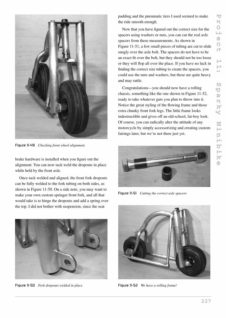
Project
11:
Sparky
Minibike
Figure 11-49 Checking front wheel alignment
brake hardware is installed when you figure out the
alignment. You can now tack weld the dropouts in place
while held by the front axle.
Once tack welded and aligned, the front fork dropouts
can be fully welded to the fork tubing on both sides, as
shown in Figure 11-50. On a side note, you may want to
make your own custom springer front fork, and all that
would take is to hinge the dropouts and add a spring over
the top. I did not bother with suspension, since the seat
Figure 11-50 Fork dropouts welded in place
padding and the pneumatic tires I used seemed to make
the ride smooth enough.
Now that you have figured out the correct size for the
spacers using washers or nuts, you can cut the real axle
spacers from these measurements. As shown in
Figure 11-51, a few small pieces of tubing are cut to slide
snugly over the axle bolt. The spacers do not have to be
an exact fit over the bolt, but they should not be too loose
or they will flop all over the place. If you have no luck in
finding the correct size tubing to create the spacers, you
could use the nuts and washers, but these are quite heavy
and may rattle.
Congratulations—you should now have a rolling
chassis, something like the one shown in Figure 11-52,
ready to take whatever guts you plan to throw into it.
Notice the great styling of the flowing frame and those
extra chunky front fork legs. The little frame looks
indestructible and gives off an old-school, fat-boy look.
Of course, you can radically alter the attitude of any
motorcycle by simply accessorizing and creating custom
fairings later, but we’re not there just yet.
Figure 11-51 Cutting the correct axle spacers
Figure 11-52 We have a rolling frame!
227

Project
11:
Sparky
Minibike
Handlebars are truly a personal choice, and since we
based our steering system on bicycle parts, the standard
bicycle gooseneck and handlebar can be installed, so
your choices are endless. I planned to do some hard
riding, so I went with a strong mountain bike handlebar,
as shown in Figure 11-53, with the ends of the handlebars
cut to a width of 18 inches. I knew the fat-boy look would
have been more pronounced with a long chrome set of
ape hangers, but because of the extreme acceleration and
trail riding I like to do, I doubt they would have held up.
The next step is to get that power plant installed into
the frame so you can start burning the rubber off your
tires! This is another stage of the build that has no strict
set of rules or common standards to follow, so before you
cut the two short tubes shown in Figure 11-54, let me
Figure 11-53 Handlebars installed
Figure 11-54 Motor mounting tubes
explain a few basic rules to follow when mounting your
motor.
The motor will probably have several places where a
bolt can be installed for mounting, but it is crucial that
your main mounting system holds the motor by its face
(the end with the drive shaft). The motor face will have at
least two large, threaded bolt holes, and may have more
than four, so you should try to use as many as you can
when planning a mounting scheme. The mounting holes
in the side of the motor are only needed to stop the motor
from banging around if the front plate flexes due to
vibration or extreme torque, and you should never
attempt to hold a motor in position by the bolt holes in the
sides of the can exclusively, or it will be damaged. The
top face is designed to take most of the stress that will be
placed on the motor, as well as hold the main motor shaft
bearings in place; therefore, it is made from a thick
machined plate of steel or aluminum and will become the
main mounting face. The motor housing can is nothing
more than a rolled piece of sheet metal, and may not even
be welded at the seams, so it will offer very little strength,
and putting stress on it may cause the permanent magnets
to become unglued, or warp the entire motor. If you want
to visualize the stress placed on a drive motor, imagine
trying to bend the motor shaft in the direction of the drive
wheel, as this is essentially what will happen as the
energy is transferred from the shaft to the chain or belt.
Knowing this, you will soon see that these two small
3/4 inch conduit tubes, shown in Figure 11-54, will be
welded between the bottom tubes just below my motor to
allow the installation of a solid mounting plate to hold
the motor by its face.
In my design, there is just enough room between the
battery box and the rear tire to cram the motor in place,
Figure 11-55 Motor mounting plates installed
228

Project
11:
Sparky
Minibike
so the two motor mounting tubes are installed directly
below the motor so that the mounting plate legs can
connect to them. Read ahead to see how and why this is
done. Your motor will likely have a very similar
mounting system, and this will work for you as well.
Figure 11-55 shows the two tubes cut and ground to fit
snugly between the bottom tubes just ahead of the rear
wheel.
Figure 11-56 shows the motor mounting tubes welded
in place. I tested the motor using the mounting plate
shown in the next few steps while the rear wheel was
installed in the frame, so there was no doubt that these
two tubes were in the correct place.
The mounting plate that will hold the motor in place
by its face is made from a few bits of 1-inch wide, 3/32
flat bar cut so that they form a face to insert the four
mounting bolts and extend to the mounting tubes
installed in the last few steps (Figure 11-57). The exact
size and length of these plates will depend on your motor
face size and drilling, so work directly from it. An easy
Figure 11-56 Motor mounting tubes welded in place
Figure 11-57 Parts for the motor mounting plate
way to get a drilling template for your motor is by laying
a piece of paper over the motor’s face, then rubbing your
greasy, dirty, mechanics’ fingers over the holes to reveal
an exact pattern. You can now punch the plate to drill the
appropriate holes.
Figure 11-58 shows the completed and drilled motor
mounting plate and the four bolts that will secure the
power plant to the plate. If your bolts holes are not
drilled exactly, do not try to force the bolts into the motor
face as you may strip the aluminum threads. Instead, just
drill the offending hole using the next largest size drill bit
you have.
The motor mounting plates are shown welded into
position in Figure 11-59. There is no magic here—just
make sure that the welds are strong and that the motor is
Figure 11-58 The completed motor mounting plate
Figure 11-59 We now have the power!
229

Project
11:
Sparky
Minibike
aligned so the shaft is perpendicular to the bottom tubes.
If your motor shaft is misaligned, you may derail the
drive chain, or cause the drive belt to prematurely wear
out. The center of the motor shaft should also be placed
so it is at the center of the drive belt or sprocket on the
rear axle. This worked out perfectly in my design,
because the motor heat sink sat just over the edge of the
bottom tube, out in the open so that air would flow into
the fins while riding, much like an air-cooled gas engine.
If you have a large motor and a heavy throttle hand,
cooling can become very important if you plan to ride for
extended periods of time. My original Sparky version
had a very small motor taken from a granny trike, and
would get seriously hot after 15 minutes of riding, or if
there was any wind or hill to deal with.
Figure 11-60 shows the motor, wheels and battery box
all nestled together in the frame without any room to
spare, exactly as I planned. This photo gives you a better
view of the resulting heat sink overhang, which will
really help keep the motor cool for just about any length
and style of riding. Of course, the battery box can only
slide out from the right side of the bike now, but
that’s OK.
Although the motor mounting plate holds the motor
very securely in place by the face so that it can take any
amount of torque delivered to the shaft, this does not take
into account the vibration the motor may encounter as
the vehicle bounces over rough terrain. I like to strap the
Figure 11-60 The battery box test fit
motor body to the frame using a hose clamp, just to be
safe. If you can’t find a hose clamp long enough to make
it around the motor and mounting tubes, then join two or
more of them together, as I have done in Figure 11-61.
As shown in Figure 11-62, the hose clamp simply
wraps around the motor body and the frame so that any
vibration will not make the motor jump around or bang
on the frame. If you have any distance between the motor
body and the frame tubing (I did not), then you should
install a stiff piece of rubber, or soft metal block, so that
the tightening of the hose clamp doesn’t bend the motor
mounting face plate. The goal is to stop vibration, not to
add any more strength to the mounting system, since it is
strong enough already.
The type of rear wheel you plan to use will dictate the
style of transmission you will use, which will be either
chain or belt. A belt drive will need an idler pulley to
maintain belt tension and adequate coverage on the
Figure 11-61 A hose clamp will stop the motor from banging
around
Figure 11-62 Hose clamp installed
230

Project
11:
Sparky
Minibike
motor side pulley. A chain drive may or may not need an
idler sprocket, depending on your ability to either move
the rear wheel back and forth, or simply find the correct
length chain. Before you choose a transmission type, if
you haven’t done so already, let me explain the pros and
cons of both chain and belt drive transmissions.
Chain drive
Chain drive is by far the most common method of
transmission for motorcycles and scooters, which is why
90 percent of the small wheels you can purchase will
have a sprocket mounting flange or a sprocket already
installed. Chain drive is considered more efficient than
belt drive for the most part, and as long as your chain is
not extremely loose, you will probably not need an idler
sprocket to pick up the slack. You could even file the
motor mounting plate holes into more of a slot shape, so
that the motor can be moved back and forth about half an
inch to deal with the chain tension. Moving the motor or
the rear wheel is a very common way to adjust chain
tension, as you know from single-speed bicycles.
The main disadvantage of a chain drive is that it is very
dirty and extremely noisy. You will realize just how
noisy a chain drive can be if you listen to a store bought
electric scooter or pocket bike drive past you. The motor
is probably 99 percent silent, but that ratchety grinding
racket will make the vehicle sound almost as loud as a
similar sized gas-powered unit. It almost seems like a
disappointment to place a loud grinding transmission on
such a clean running, neighborhood friendly vehicle that
could be almost 100 percent silent, but the choice is
ultimately up to you.
Belt drive
As you can probably tell by now, I personally favor the
belt drive solution because it is absolutely silent, doesn’t
spit grease all over the place, needs no adjustment, and
can utilize parts found in an old washing machine or
dryer. It is said that belt drive is not as efficient as chain,
but to be honest, I have tried them both on the same
vehicle on more than one occasion, and noticed
absolutely no difference in top speed or overall range, so I
disagree based on my own personal experiences. Another
advantage of a belt drive is that it will take some of the
shock away from the motor if it is made to accelerate at a
dangerous rate, which is what could happen if you decide
to not use a motor controller and simply go for the
inexpensive contactor throttle. With a chain drive, there
is no slip, so you’d better hold on to your lug nuts if you
have a simple contactor and a powerful motor, because
you will accelerate with as much energy as your batteries
can deliver to the motor. With the motor I used, this
would result in a runaway motorcycle and a sore butt in a
real hurry. With a belt drive, there is some slip under
extreme load, and this slip is fully adjustable by adjusting
an idler pulley, so you can tailor the transmission for the
type of power and motor controller you plan to use.
In my design, I have a fairly tight belt for limited slip due
to the smooth ramping curve of my motor controller.
I can certainly do wheelies and burnouts if I like, but this
is by choice, not when I least expect it.
As shown in Figure 11-63, a belt or chain tensioner is
simply a flat pulley or sprocket attached to a rod that is
pressed into the belt or chain by a spring. The parts were
salvaged from a dead washing machine, but these flat
idler pulleys can be found at most hardware stores and
appliance repair shops. The idler pulley rides in the flat
side of the belt, so it does not have a typical V-groove on
its surface.
The idler pulley or sprocket (if necessary) will be
mounted to the motor mounting plate using a simple bolt,
as shown in Figure 11-64. Read ahead a few steps and
you will see how these parts come together in order to
form the idler system. Again, if you are using a chain,
you may not need an idler system, since you could simply
slot out the motor mounting holes to allow some degree
of chain adjustability. To make slots of the holes, just drill
Figure 11-63 Belt tensioner parts
231

Project
11:
Sparky
Minibike
Figure 11-64 Idler pulley mounting bolt
the same size holes directly beside the original holes, and
then use a small file to create the slot between them.
Figure 11-65 shows the idler pulley arm and pulley
mounting bolt which is made by cutting the head off a
bolt that will fit through the bearing of the idler pulley,
and then welding it to a small bit of flat bar or angle iron.
The size and position of this idler system depends on
your motor, mounting plate, and belt.
The idler pulley is fastened to the bolt installed in the
last step so that it looks like Figure 11-66. The pulley
should spin freely on its roller bearings, yet be securely
fastened to the arm so that it doesn’t rub on the arm.
The idler arm will be fastened to the bolt that is
welded to the motor mounting plate. By using a sleeve, it
can be positioned up or down, pushing the idler pulley
into the underside of the belt. As shown in Figure 11-67,
a small piece of tubing or a spacer that fits around the
bolt is welded to the other end of the idler arm. This is a
Figure 11-65 Idler pulley arm and pulley mounting bolt
Figure 11-66 Idler pulley installed
Figure 11-67 Idler arm mounting sleeve
similar idea to that used for the front wheel mounting
bolt and spacers.
As shown in Figure 11-68, the idler arm is free to pivot
around the bolt on the motor mounting plate, so that the
idler pulley can move up or down into the underside of
the drive belt. This will allow more of the belt to ride in
the small motor-mounted pulley, creating great friction
and less slip. The amount of controlled slip will be
determined by how hard the idler pulley is pushed up
into the belt.
Figure 11-68 Idler arm in position
232

Project
11:
Sparky
Minibike
To figure out what size of belt you will need, push the
idler pulley up about halfway, then run a measuring tape
around the outside lip of both pulleys, as shown in
Figure 11-69. This measurement will be close enough to
purchase the correct length belt, which will probably be
rounded to the nearest half inch. Notice the ratio of motor
pulley to wheel pulley (1:3). The 2-inch motor pulley and
6-inch wheel pulley gives us that magic 1:3 ratio for an
estimated top speed of 30 miles per hour and loads of
acceleration. If these were sprockets, they would be
about the same diameter, but would be rated in numbers
of teeth, rather than dimensions. A sprocket ratio of 15
teeth on the motor to 45 teeth on the wheel would be
about right.
The perfect length drive belt will enter and exit the
motor pulley at about the same angle, as shown in
Figure 11-70. This arrangement puts plenty of belt
around that small motor pulley, greatly increasing the
friction. If the system had no idler pulley, and the same
belt tension, there would be a large amount of slip due to
the fact that only a small percentage of the motor pulley
would have any belt in the groove. All we need now is a
spring to hold that idler in place.
Here is where you can do a little magic to tailor the
amount of maximum acceleration your transmission can
deliver. If you have a well-behaved motor controller with
a sensible acceleration ramp, then this idler spring can be
stretched out so that the pulley is quite tight against the
belt (it is difficult to push the idler pulley down by hand).
This spring is taken from an old mattress box spring, and
is quite difficult to pull apart by hand, although I can
Figure 11-69 Measuring the belt size
Figure 11-70 Test fitting the drive belt
muscle it in place with a pair of pliers. As you can see in
Figure 11-71, the spring is held under tension by a nut
welded to the fork leg so that the spring is pushing the
idler pulley into the drive belt. If you want to play around
with limited slip, then you could install a small plate with
multiple spring mounting holes, or simply use different
sized springs. Many washing machines, dryers and
furnaces use a system just like this, so keep that in mind
as you scavenge for parts.
Besides the connection from the batteries to the motor,
the rest of the bike is simple bits and pieces designed to
hold the accessories such as seat, lights, fenders, etc. Feel
free to go crazy on customization and additions here;
there is certainly no strict set of rules and guidelines
when it comes to these parts. Figure 11-72 shows the few
bits of 1/8-inch scrap flat bar I planned to use to create a
sturdy seat mounting platform just over the rear wheel.
I wanted a big phat seat placed directly over the rear
wheel as low as possible, so that the rider would sit low
and comfortable on the little hog with just enough knee
Figure 11-71 Idler tension spring
233

Project
11:
Sparky
Minibike
Figure 11-72 Seat mounting plates
room for the handlebars. Because of the well-behaved
motor controller I planned to install, combined with the
front heavy weight added by the batteries, the rider’s
weight would be near the rear of the bike, with minimal
risk of an unplanned wheelie. As shown in Figure 11-73,
I cut a bit more from the tail of the main spine tube and
installed the seat mounting plates, so that my large seat
would be securely held in place by four large
woodscrews.
I decided to install all the little stuff before wiring up
the motor controller, so the temptation to drive the
unfinished, unpainted mini bike would not get me this
time. I made fender mounting plates for the front and rear
and a headlight mounting tab from various bits of scrap
steel and flat bar. Shown in Figure 11-74 are the front
fender mounting plate and the headlight tab.
Fender style can really lend a lot to the overall
appearance and attitude of your project, so feel free to
use your imagination here. A very stylish and strong
fender can be made by cutting the sides and top from
some thin (1/32) sheet metal using a jigsaw, as shown in
Figure 11-73 Seat mounting plates installed
Figure 11-74 Let there be light
Figure 11-75. I simply traced a pot lid that was slightly
larger than the wheels to create the fender sides, then
gave them a little flair at the ends to look like those big
Harley fenders. These fenders will cover quite a bit of the
wheel, and will be strong enough to jump up and down
on if sitting on the ground.
There are no fancy tools or mystical black arts used in
my garage, buddy, just hard work, basic tools, and a lot
of junk! To form the nice round fenders, I just tack weld
the side pieces to the top strip, and bend the top strip
around the side pieces as I tack weld about every inch or
so, as shown in Figure 11-76. The resulting fender is
perfectly round, as if rolled by an expensive tool that I
don’t ever plan to own.
The resulting fender shown in Figure 11-77 is what
you get by rolling the top strip along the end pieces as
you tack weld. As you can imagine, fenders, fairings, and
many other shapes can be made using this simple yet
highly effective system.
Figure 11-75 Cutting the fender pieces
234

Project
11:
Sparky
Minibike
Figure 11-76 Roll and weld
Figure 11-77 Tack welded fender
Once tack welded together, the entire outside joint can
be welded and ground smooth in very little time to reveal
the perfectly smooth fender, as shown in the foreground
of Figure 11-78. After welding the entire joint, I rough
grind the welds with a coarse disc, and then take a
sanding disc to clean up the weld until it looks like it was
professionally made. Do not weld the inside of the fender
joint, or you will warp the fender, pulling the sides
together.
I had some 2-inch thick rigid packing foam in my
garage, so I thought it would make a perfect seat material
to give the seat a real phat look. As shown in
Figure 11-79, I first cut the 3/4 plywood to form the seat
base, and then traced the area on the foam to rough cut it
with a razor knife. This seat is about the same size and
shape as a granny trike seat, but feel free to build to suit
your style.
Figure 11-78 Weld and grind the edges
Figure 11-79 Phat seat requires phat foam
Figure 11-80 Foam trimmed and glued to the wood
Once I glued the seat foam to the base, I took the
grinder and traced around the edge of the wood to make
the foam follow the exact perimeter of the seat base. As
shown in Figure 11-80, the foam is exactly the same
shape as the seat, so it is now ready to be covered.
235

Project
11:
Sparky
Minibike
Figure 11-81 Upholstery work is an art
Figure 11-81 shows my “poor man’s” method for
upholstering a seat. I simply take the ultra high-quality
“pleather” and stretch it as hard as I can around the seat,
using as many staples as possible to hold it in place. If
you can muscle the material with enough force, you will
get almost all of those wrinkles to flatten out, reducing
the “Christmas present” look in your seat. A sewing
machine and proper seaming would be a much better
alternative, but I am afraid the Atomic Zombie garage
has no such equipment!
How many staples are enough? The real question is,
how many do you have? I stretch that material until my
face turns red, and then blast as many staples as I can
into the material to hold it in place. It is pretty amazing
how much you can force that material to conform to the
seat, even a seat with so many curves, like the one shown
in Figure 11-82. When you think you have enough
staples, add more.
Figure 11-82 I keep the staple company in business
Considering the crudeness of my upholstering
methods used, the seat shown in Figure 11-83 actually
looks pretty good! Once the material was stretched and
stapled, I tapped in some copper thumb tacks with a
hammer to give the seat a more authentic look. There are
only a few wrinkles near the base of the seat, but I
actually think they add to the look.
You now have a place to sit, but your feet need a place
to rest, so the foot pegs are next on the list of things to
do. The perfect foot pegs can be taken from a freestyle
BMX bike—these are light yet strong aluminum tubes
that bolt onto the rear axles so riders can stand on them
and pull stunts. To fasten them to our frame, simply weld
a bolt onto the front of the bottom tube and place the
pegs into the bolt. As shown in Figure 11-84, I used a 3/8
bolt and then drilled out the foot pegs to fit over this bolt.
Figure 11-83 Completed hog-style seat
Figure 11-84 Foot peg mounting bolts
236

Project
11:
Sparky
Minibike
Locknuts were then used. These foot pegs can be found
as accessories anywhere that sells bicycles and parts.
As shown in Figure 11-85, the foot pegs should be
installed onto the frame on a slight upwards angle, so that
they do not strike the ground when your mini bike leans
into the corners. Twenty-five degrees should be more
than enough angle to allow the mini bike to lean into
corners. Because the bike only has a few inches of
ground clearance, the foot pegs also work as a kickstand
if you simply let the bike rest on them.
The battery box was made to be easy to swap out or
remove for charging, so it is held to the frame using this
tab and nut system, as shown in Figure 11-86. A small bit
of flat bar, or even a washer with one side ground flat, is
welded to the battery box near the top and at the bottom,
so all you have to do is remove two bolts to pull the
battery pack out. The easiest way to get the nut in the
correct place over the hole is to install the bolt to the nut,
Figure 11-85 Foot pegs are installed to allow the bike to lean
in turns
Figure 11-86 Battery box mounting tab
and then tack weld it to the frame so it ends up in the
correct position.
Figure 11-87 shows the bolt holding the battery box
securely in place. There is another nut and tab just like
this one at the bottom of the battery pack so that it does
not rattle around under heavy vibration.
This is the last time during this project that I will
ramble on for more than a paragraph, since it is almost
time to paint and ride, but since it is time to install some
type of motor controller, like the one shown in
Figure 11-88, a little bit more information needs to be
given.
Simple contactor
The simplest and least expensive method of transferring
power from your battery pack to the motor is through a
simple switch called a “contactor,” which often looks
Figure 11-87 Battery box bolted onto the frame
Figure 11-88 The motor speed controller
237

Project
11:
Sparky
Minibike
like a large doorbell that will be mounted on the
handlebars so that you can press it with your thumb. This
is nothing more than a large-current-capable switch that
completes a circuit so that 100 percent of the available
horsepower is delivered instantly to the rear wheel.
Obviously, a powerful motor and large battery pack will
cause jerky, wheelie-prone take-offs, but this can be
reduced by using a drive belt with a bit less tension, or by
kicking off with one foot so that the bike is rolling a little
bit before the motor is engaged. To vary your speed,
simply toggle the contactor switch as needed. If you
would like to see the many available styles of contactors,
just do an Internet search for “ev contactor.” You will
need to choose a contactor that can handle your drive
motor’s “stall current,” or the battery pack’s maximum
discharge capacity, since this is the current that will flow
through the switch as your motor is asked to accelerate at
full capacity from a dead stop.
I have also made contactors from brass bolts, and by
installing cables into the solenoid plungers of automotive
starter solenoids, but unless you are certain of what you
are doing, this approach is not recommended because
you could create a contactor that may become stuck in
the on position. For the record, Sparky version 1 had a
simple contactor made by inserting a brass bolt through
the handle of a plastic brake lever, so that the bolt would
contact the metal handlebars closing the circuit. This
system did work quite well, but was prone to heating up
and always threw a huge spark when starting from a dead
stop, hence the name Sparky!
Motor speed controller
A motor controller is a far better approach for delivering
the battery current to the motor, because you will have
full control over the acceleration, top speed, and
sometime braking. Motor speed controllers send a
pulse-width modulated signal, varying in duty cycle from
zero to 100 percent to the motor at a high rate of
frequency, so that the motor acts as if you are varying the
current. If you had a simple contactor, you could pulse it
on and off to try to control your speed. However, the
motor speed controller has an onboard computer that
does this hundreds of times per second, so the speed
control is ultimately smooth. A throttle that has either a
lever or conventional twist grip is installed on the
handlebars, and the speed control is so fine that you can
make the wheel just barely turn, or rip up the ground
with rocket-like acceleration if your motor is capable of
doing so. A motor speed controller will also limit the
current to the motor, so you will not burn it out if you try
to push it too hard, and the acceleration will follow some
type of ramp, so an accidental wheelie will not occur if
you open that throttle too far from a dead stop.
The downside of a real motor speed controller is of
course the price. I highly recommend that you give this
option some real consideration, as it will make your
riding experience so much more enjoyable, and allow
you to keep your machine under complete control,
especially in a crowded area where you need precise
control of your vehicle. You can also limit the top speed
for younger riders, and lock the mini bike when not in
use, by adding a key switch if it is not already part of the
controller kit. Choosing a controller is much like
choosing a simple contactor; you must choose a
controller that will handle the rated capacity of your
motor at the chosen voltage. Most motor speed
controllers do have current limiting, so choosing a lower
current controller than required will usually only result in
poor performance, but there is a limit, and if your
controller is too “wimpy,” it will burn out on hills or even
when you ride against the wind for too long.
My motor controller is an Alltrax golf cart unit rated
for 275 amps continuous, and 400 amps peak for 30
seconds. What this means is that when I am starting
from a dead stop, the motor will get 400 amps if my
battery pack can deliver it (unlikely), and then the
controller will be happy delivering 275 amps to the
motor all day or until the batteries give it up. This
controller is actually overpowered for my motor and
batteries, but I know that there is virtually nothing I can
do to blow the controller, and it will climb hills, spin dirt,
and outperform most store-bought scooters all day
without even getting warm.
When you do a search for “ev parts,” or “motor
speed controllers,” you will find a lot of great
information, and there are many different products
available to choose from. Like all parts, try to find a
reputable company, and ask them for advice when
choosing a controller. You really want to avoid an
underrated controller for your motor, and if your budget
allows, purchase the next step up just to be safe. I plan to
build many different electric vehicles with this motor and
238

Project
11:
Sparky
Minibike
controller, so I am confident it will hold up to whatever
abuse I throw at it.
Regenerative braking
For typical riding, most of my braking comes from the
resistance that the controller puts across the motors
terminals when I release the throttle. What is happening
is that the motor is no longer receiving current; it is being
forced to generate it, which puts a load on the motor,
effectively slowing it down. If your controller has
full-blown regenerative braking (regen), then you will
not only get a large amount of smooth, throttle-controlled
braking ability, but your batteries will get a little bit of
charging as the controller pumps current from the motor
back to the batteries. In a large vehicle, this can
significantly increase the run time, but in a vehicle like
Sparky, this is just an added bonus, especially on a
design like mine with no built-in wheel brakes.
Obviously, if your controller has no regen, then you’d
better have at least one decent wheel brake for safety.
Depending on the level of regen your controller has,
wheel brakes may not even be necessary, although a bad
controller failure could also deplete all your braking
ability. A simple motor pulley brake will be presented
later as well, just in case you are limited by the wheels
and the motor speed controller.
I decided to complete the frame by capping off the
extra tubing left over when I cut the bottom tubes rather
than cutting them off. I inserted a pair of chrome lug nuts
into the ends of the tubes and welded them in place, as
shown in Figure 11-89. After painting, I brushed off the
paint at the tips of the lug nuts with some steel wool.
These small details make a huge difference, if you plan
to sit in one place long enough to show off your custom
creation. Take this opportunity to check over all the
welds, and clean up any rough spots and holes.
Apply a good metal primer after cleaning up the parts
with some fine sandpaper. I know it’s torture to wait for
primer and paint to dry, but if you follow the instructions
and do it right, then a simple spray-can job can look just
as good as a professional job. I normally prime the parts
then let them sit for a day, and then do the spray painting.
The spray paint should be left for a few days to cure
before you assemble the bike, although I will admit that
sometimes my impatience gets the best of me. Fresh
Figure 11-89 Capping the tubing ends with chrome lug nuts
paint is easy to scratch and chip for at least a week after it
dries, so be careful. Figure 11-90 shows the freshly
primed parts taunting me to work faster.
Figure 11-91 shows a fresh-looking, bright orange
Sparky assembled again after the paint has cured for a
week (I seriously did wait a week). The simple orange
with black accents actually turned out quite well, and the
little mini bike was starting to resemble a little hog as
planned.
Figure 11-92 shows Sparky with all the major
components installed, waiting to have the wiring done.
Take your time and solder all wires using the proper
clips, following the wiring diagram that came with your
motor controller. Do not get lazy and leave out the
recommended fuses and safety switches just in case you
have a crossed wire, or the only smoke show you will be
Figure 11-90 Frame parts primed
239

Project
11:
Sparky
Minibike
Figure 11-91 Shiny and new!
Figure 11-92 Waiting for a wiring job
creating is one where all the Metal Oxide Silicon Field
Effect Transistors (MOSFETs) in your controller
explode. There is no standard wiring diagram I can show
you since each motor controller and contactor will have
its own wiring map, but I can tell you that you have a
50 percent chance of hooking up your motor in reverse!
Most of these small DC motors, mine included, have no
polarity and rotation shown on the terminals, so you may
end up hitting that throttle and going in reverse. This will
not cause any damage, but your first attempt at spinning
the drive wheel should be done on blocks before your
first test ride.
Most of the wheels available for small scooters and
mini bikes will have some type of brake already built
into the wheel in the form of drum brakes or band
brakes. It is a matter of installing a bicycle brake lever as
shown in the manufacturer’s instructions, in order to
have brakes on one or both wheels. My wheels did not
offer any simple method of adding a brake, but since my
motor controller had a decent level of braking by simply
letting off the throttle, I did not bother trying to install
any other brakes. If I had a simple contactor rather than a
motor controller, I would certainly need some type of
brake, so I devised the system shown in Figure 11-93, in
case you have brakeless wheels and a simple contactor.
The brake is just a bicycle pull brake with the pads
turned sideways so that they grab hold of the aluminum
drive pulley when I engage the brake lever. It may not
look like much, but remember that the gear ratio between
the motor pulley and the wheel pulley is 1:3, so this
brake is effectively grabbing a wheel of 6 inches in
diameter. Using only this brake to stop, I can bring the
mini bike to a dead stop from full speed in a distance of
about 20 feet, which is not too bad.
If you take a sharp knife and cut the brake pads to
conform more to the pulley body, then the braking
power will be increased even more. Some production
scooters and pocket bikes use the same system as this for
brakes.
After looking at so many photos of this mini bike
being built, you may have forgotten how small Sparky
really is! Figure 11-94 brings this into perspective,
showing how little real estate he really occupies. Many
onlookers chuckle as I unload Sparky from the back of
Figure 11-93 A sneaky brake, in case you find it necessary
240
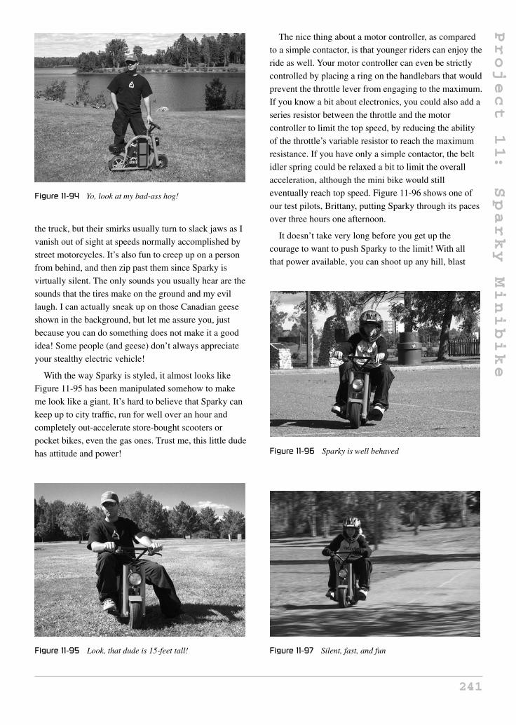
Project
11:
Sparky
Minibike
Figure 11-94 Yo, look at my bad-ass hog!
the truck, but their smirks usually turn to slack jaws as I
vanish out of sight at speeds normally accomplished by
street motorcycles. It’s also fun to creep up on a person
from behind, and then zip past them since Sparky is
virtually silent. The only sounds you usually hear are the
sounds that the tires make on the ground and my evil
laugh. I can actually sneak up on those Canadian geese
shown in the background, but let me assure you, just
because you can do something does not make it a good
idea! Some people (and geese) don’t always appreciate
your stealthy electric vehicle!
With the way Sparky is styled, it almost looks like
Figure 11-95 has been manipulated somehow to make
me look like a giant. It’s hard to believe that Sparky can
keep up to city traffic, run for well over an hour and
completely out-accelerate store-bought scooters or
pocket bikes, even the gas ones. Trust me, this little dude
has attitude and power!
Figure 11-95 Look, that dude is 15-feet tall!
The nice thing about a motor controller, as compared
to a simple contactor, is that younger riders can enjoy the
ride as well. Your motor controller can even be strictly
controlled by placing a ring on the handlebars that would
prevent the throttle lever from engaging to the maximum.
If you know a bit about electronics, you could also add a
series resistor between the throttle and the motor
controller to limit the top speed, by reducing the ability
of the throttle’s variable resistor to reach the maximum
resistance. If you have only a simple contactor, the belt
idler spring could be relaxed a bit to limit the overall
acceleration, although the mini bike would still
eventually reach top speed. Figure 11-96 shows one of
our test pilots, Brittany, putting Sparky through its paces
over three hours one afternoon.
It doesn’t take very long before you get up the
courage to want to push Sparky to the limit! With all
that power available, you can shoot up any hill, blast
Figure 11-96 Sparky is well behaved
Figure 11-97 Silent, fast, and fun
241

Project
12:
LongRanger
Scooter
Figure 11-98 Still going strong after hours of vigorous riding
up the dirt, pull wheelies, and even give a buddy a
ride, although sitting on the frame tubing sure does
hurt!
With all that vigorous riding, Sparky may wear you
out before the batteries need a recharge, but when the
time comes to plug in, you can expect to be back on the
trails within 4 to 6 hours, depending on the size of your
battery pack and speed of your charger. If you can’t get
enough, just have two battery packs so you can cycle
them for non-stop fun. Oh, and when you finish your
custom electric mini bike, do remember to send us a
photo for our gallery, as we love to see what other garage
hackers are building!
Project 12: LongRanger Scooter
The LongRanger fills a gap between the
electric-motor-assisted mountain bicycle and the fully
street-legal electric motorcycle or scooter, allowing you
to commute great distances at speeds typical of a standard
human-powered bicycle. Because the LongRanger looks
and feels much like a standard mountain bike, it will
happily live on bike paths and trails normally off-limits
to larger motorized vehicles. The LongRanger can be
made to travel well over 62 miles (100 kilometers) on a
single charge, and will do so at speeds that only a top
athlete could keep up for any real distance. Oh, and it
does all this without making any pollution or noise
whatsoever! Because the LongRanger is built around the
battery pack and the type of hub motor you choose, you
can build the base vehicle to suit your needs, altering the
top speed, acceleration, weight or range.
It’s a good idea to read over the entire plan once before
hacking up any bikes or heading to the scrapyard on a
search for parts. By reading ahead, you will see why a
certain part was chosen, and get some ideas on how to
modify the design to suit your needs. With even a slight
change in a few of the main frame tubes, you could make
a completely different looking chopper, even though the
core design has been followed. Don’t be afraid to try new
things, and remember that hard work is what makes this
hobby successful, not spending money on
mass-produced products. Long live the real custom!
Regardless of the size and number of batteries you
plan to install, you will need a front wheel, suspension
fork, and matching head tube from a sturdy mountain
bike. To ensure that all the parts fit together properly, it is
recommend that you salvage these parts from the same
bike, preferably one in decent condition. I actually
purchased a brand new mountain bike on sale at the
hardware store, and then stripped all of the parts off,
leaving what you see in Figure 12-1.
Often, you can purchase a decent quality,
full-suspension mountain bike on sale for a hundred
bucks, which is not bad considering you end up with a
new aluminum front wheel, tire, suspension system,
frame, and one rear shock. I know, the quality of an
242Copyright © 2008 by The McGraw-Hill Companies, Inc. Click here for terms of use.

Project
12:
LongRanger
Scooter
Figure 12-1 Choosing a front wheel and suspension fork
inexpensive department store bike is nowhere near that
of a high-end mountain bike purchased from a quality
dealer, but at least all the parts are new, and the frame is
made of steel, so it can be welded. I ended up using the
rear of the bike to make a tadpole trike called the
StreetFox, so a hundred bucks was actually a great deal.
Regardless of where you acquire the parts, you will
need what is shown in Figure 12-1—a front wheel and
suspension fork, a matching head tube with at least a
small portion of the frame tubing still intact, two similar
rear shocks, and the front brake hardware. Don’t worry
about the rear triangle of the frame, as it will not be
needed.
As you can see in Figure 12-2, the entire front of the
mountain bike will be used, which is why it is optimal to
work with parts that fit properly together and are in good
working order. Stand up the frame with the front tire
fully inflated so that the head tube is at the angle it was
when the bike was complete, or at an angle typical of a
standard bicycle, which is usually somewhere between
Figure 12-2 Using a guide bar to make a straight cut
72 and 74 degrees. If your donor frame does not include
rear hardware or a rear wheel, like my frame shown in
Figure 12-2, you will have to figure out a way to stand up
the frame so that the head tube is at the correct angle,
since the cutting line is derived this way. As you can see
in Figure 12-2, I have placed the rear of the frame on a
plastic bucket and a bit of scrap wood, so that the head
tube is at roughly the same angle it would have been if
the entire bike were still together.
Head tube angle is measured by extending an
imaginary line to the ground and then taking the angle of
this line with that of the horizontal ground. Rather than
messing around this way, simply roll a functional bicycle
up next to your supported frame and match up the angles
as closely as you can. A few degrees either way is not
going to make a huge difference in the completed
vehicle. The angle of my head tube, as shown in
Figure 12-2, was determined by placing another
mountain bike alongside the donor frame for reference,
as I propped up the rear of the frame. My head tube angle
is approximately 73 degrees.
Also shown in Figure 12-2 is a length of flat bar placed
vertically, 4 inches back from the edge of the front tire.
This flat bar is used as a guide to mark a line on the top
tube and down tube for cutting. Since the battery box will
be a perfectly square box riding parallel to the ground,
the frame cut lines are to be marked so they are 90
degrees to the ground. To do this, either have a helper use
a 90-degree square to check the angle of your guide bar
with the ground, or use a level to check this angle as you
hold the guide bar against the frame.
Figure 12-3 shows the frame tubing marked for cutting
after ensuring that the guide bar was placed 4 inches
behind the edge of the front tire, and at 90 degrees to the
ground so it was perfectly vertical. A black marker is
used to mark the line, which needs to be the same on
both sides of the frame.
Once the cut lines have been clearly marked on both
frame tubes, use a hacksaw or cut-off wheel in your
grinder to cut away the front of the frame from the rest of
the frame. I use a cut-off disc (zip disc) for all my metal
cutting because it’s much faster and more accurate than a
hacksaw, but do be careful when hacking up
bicycle frames. On the first cut through a complete frame
tube, the frame may start to collapse on the grinder disc if
under tension, so keep this in mind as you complete any
cuts, holding on to the grinder with both hands. To avoid
243

Project
12:
LongRanger
Scooter
Figure 12-3 Marking the frame for cutting
this, the last half inch of the cut can be made with a
hacksaw to avoid any disc snagging that might occur.
Figure 12-4 shows the front of the frame, including a
head tube and a few inches of top tube and down tube.
To aid welding and avoid filling the garage with horrific,
burning paint fumes, the paint was removed around the
joint ahead of time using some sandpaper. A sanding
disc (flap disc) is also an easy way to remove paint
easily.
Although we will discuss the hub motor, controller and
batteries in greater detail later, you will need to know the
dimensions of the batteries you plan to install on your
version of the LongRanger, in order to continue building
the frame. If you have not decided on a brand or type of
hub motor and batteries yet, then read ahead so you can
see how these components will affect the range, weight,
and speed of your final design. The obvious goal of the
LongRanger is of course long range, so batteries much
larger than those considered typical of an
Figure 12-4 The front of the frame has been cut
electric-assisted bicycle will be used. As you will soon
see, the frame is actually built around the batteries, since
they are the key element in the entire design.
Figure 12-5 shows the huge size difference between
the standard, hub motor kit batteries and the ones I plan
to install in the LongRanger. The small batteries are rated
at 7 amp hours each, and the larger ones are rated at 32
amp hours each, so the expected range of the larger
batteries is about four and a half times more. The small
batteries measure 6" by 2.5" by 4", and the large ones
measure 7.75" by 5" by 7". Let’s discuss battery size
versus expected range.
There are many types of battery chemistries, and each
has certain advantages depending on the intended use.
Let me make this choice very simple—you should only
use sealed lead acid (GEL) batteries for this project.
Unlike a typical automotive lead acid battery, a sealed or
GEL battery does not have free-flowing liquid, nor does
it need maintenance such as “topping up” the fluids, so
there is no chance of spilling any corrosive liquid on
your vehicle or yourself. Sealed batteries are often
labeled as wheelchair or recreational batteries, and the
obvious sign that they are sealed is the lack of any type
of filling or maintenance valve on the top of the battery.
Sealed batteries may cost a little more than the
equivalent size wet-cell battery, but the extra cost is
worth it in terms of safety and overall battery quality.
The real question is: how far do you want to travel on
a single battery charge? Sure, you could go to the battery
store and tell them to give you three of the largest GEL
batteries they have, but do you really need to commute
half way across the country? Also, the larger batteries
can get very large and heavy, so you may be very
Figure 12-5 Comparing battery sizes
244

Project
12:
LongRanger
Scooter
uncomfortable straddling a 12-inch-wide battery box.
The batteries shown in Figure 12-5 have never needed a
recharge, even after two days of lengthy riding, so as a
guide, 32-amp-hour batteries will be more than enough
for any single journey you may want to undertake. There
are many sizes of GEL batteries in the smaller (under 40
amp hours) range, so your best bet is to look at the
estimated range of your hub motor kit with its current
batteries and work from there. If the original
10-amp-hour battery pack claims 25 miles (approx. 40
kilometers), then it is a safe guess that a 30-amp-hour
battery pack should deliver 120 kilometers of range. Of
course, I would divide any manufacturer’s range claim
by 1.5, as they have been known to exaggerate!
OK, let’s sum up all this battery talk. Only purchase
GEL batteries, and make sure all of them are the same
size and age. A battery larger than 35 amp hours is
probably too large, and anything less than 20 amp hours
might be too small. Use your original battery’s capacity
and range as a guide, but take manufacturers’ claims with
a grain of salt!
Figure 12-6 shows a stack of three GEL batteries
separated by blocks of wood so that the connecting
terminals do not rub on the underside of the battery
above. This battery pack will deliver 36 volts at 32 amp
Figure 12-6 The mighty 36-volt stack
hours. Voltage is the sum of all batteries in series, so
3 × 12 volts equals 36 volts. Amp hour rating is the same
rating as a single battery in a series connected pack, so
since each of these batteries is 32 amp hours, that is the
overall amp-hour rating of the pack. Why three batteries?
Simple—because the original pack was three batteries
and I did not want to overpower the hub motor, or have
to search for a different voltage charger. If you add an
extra battery to create a 48-volt pack, your hub motor
may have no problem with the higher voltage, and it will
actually run a bit faster, although you will now have to
source a 48-volt battery charger, and make room for one
extra battery. Unlike a higher amp-hour rating, with more
voltage, range will not increase.
Unless you know what you are doing with batteries,
controllers and chargers, the best bet is to simply
increase the amp-hour rating of your batteries, and use
the same number of batteries and charger that came with
the original kit. My charger is only rated for a 1-amp
charging rate, which is very small, but it takes care of the
32-amp-hour pack overnight if I do not run it down too
far. The typical 36-volt charger is between 2 and 4 amps,
so you will be fine.
As shown in Figure 12-6, you must stack up your
batteries in such a way that the connection terminals do
not rub on the underside of the above battery. Some small
pieces of 2 × 4 wood seem to do the job perfectly. Solid
rubber hockey pucks may also be a good choice if you
have access to them.
Once you have your batteries stacked up and insulated
from each other, you can begin making the battery pack
rails by using the actual stack of batteries as a guide. As
shown in Figure 12-7, four lengths of 1/16-inch thick,
1-inch-wide angle iron have been cut and strapped to the
battery pack using an elastic cord. These four lengths of
angle iron will form the side rails of the battery pack, and
should reach from the base of the lower battery to 1 inch
above the top of the upper battery terminal.
Be careful when handling the metal bars around the
batteries, especially if the battery terminals are not
insulated with a plastic cover. Dropping the metal across
the battery terminal will not only cause an extremely
loud and startling spark, it could damage the battery or
cause a nasty burn. You can safely come in contact with
the terminals because the voltage is much too low to
deliver a shock, but there is certainly enough amperage
there to weld steel!
245
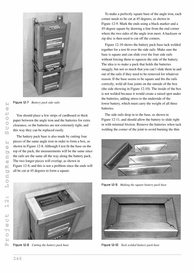
Project
12:
LongRanger
Scooter Figure 12-7 Battery pack side rails
You should place a few strips of cardboard or thick
paper between the angle iron and the batteries for extra
clearance, so the batteries are not extremely tight, and
this way they can be replaced easily.
The battery pack base is also made by cutting four
pieces of the same angle iron in order to form a box, as
shown in Figure 12-8. Although I test fit the base on the
top of the pack, the measurements will be the same since
the rails are the same all the way along the battery pack.
The two longer pieces will overlap, as shown in
Figure 12-8, and this is not a problem since the ends will
all be cut at 45 degrees to form a square.
Figure 12-8 Cutting the battery pack base
To make a perfectly square base of the angle iron, each
corner needs to be cut at 45 degrees, as shown in
Figure 12-9. Mark the ends using a black marker and a
45-degree square by drawing a line from the end corner
where the two sides of the angle iron meet. A hacksaw or
zip disc is then used to cut off the corners.
Figure 12-10 shows the battery pack base tack welded
together for a test fit over the side rails. Make sure the
base is square and can slide over the four side rails
without forcing them to squeeze the side of the battery.
The idea is to make a pack that holds the batteries
snuggly, but not so much that you can’t slide them in and
out of the rails if they need to be removed for whatever
reason. If the base seems to be square and fits the rails
correctly, weld all four joints on the outside of the box
(the side showing in Figure 12-10). The inside of the box
is not welded because it would create a raised spot under
the batteries, adding stress to the underside of the
lower battery, which must carry the weight of all three
batteries.
The side rails drop in to the base, as shown in
Figure 12-11, and should allow the battery to slide right
in with minimal friction. Remove the batteries when tack
welding the corner of the joint to avoid burning the thin
Figure 12-9 Making the square battery pack base
Figure 12-10 Tack welded battery pack base
246

Project
12:
LongRanger
Scooter
Figure 12-11 Installing the side rails
plastic casing of the battery. At this point, only tack weld
the side rails in place; this way, the entire box can be
squared up once the top has been added.
The top of the battery box is made from 1-inch flat bar,
or by cutting a length of angle iron into two pieces by
cutting it along the bend. Since the batteries need some
way in and out of the battery pack, angle iron could not
be used to make the top of the box as it would seal the
opening. The top four bars shown in Figure 12-12 are cut
so they form a box of exactly the same dimensions as the
box on the base of the battery pack. Only tack weld the
bars in a few places so you can square up the entire
battery pack by forcing it into shape. This is a good time
to test fit a battery to make sure it slides into the pack
without much resistance.
Figure 12-12 Adding the top bars
Once you have your battery pack tack welded together
and squared up, you can finish welding all the outer
joints to complete the pack. The completed battery pack
is shown in Figure 12-13, with all the outer joints fully
welded to give great strength to the box. None of the
inside joints are welded because this would make it
difficult to insert the batteries, and is not necessary for
strength. You’d better test fit all three batteries one last
time to ensure that heat distortion did not pull the box out
of square.
The LongRanger is a battery box with wheels! On a
regular diamond frame bicycle, there is little possibility
of carrying 60 pounds of large batteries on the frame
without dangerously overloading the frame or upsetting
the balance. On the LongRanger, carrying the batteries
is the purpose of the frame, so the most important part of
the frame is a battery box holder. This part of the frame is
called the center frame, and it is simply a square frame
around the battery pack made of 1.5-inch steel tuning
with a wall thickness of 1/16 inch. The four pieces are
shown in Figure 12-14.
This tubing can be ordered from any steel supplier, and
is very easy to cut and weld. Steel suppliers like to rate
tubing wall thickness using a gauge number, so 1/16 wall
tubing will be called 16-gauge tubing, and although there
is a slight difference between the two, your best bet is to
tell them you want a length of 1.5-inch square tubing
with a wall thickness as close to .0625 of an inch (1/16)
as you can get. If you are a heavy rider (over 300
pounds), then you should ask for the next size after that,
which will most likely be 14-gauge tubing, or .078-inch
wall tubing.
Figure 12-13 Battery pack welding completed
247

Project
12:
LongRanger
Scooter
Figure 12-14 Tubing for the center frame
How much tubing you will need is completely
dependent on the perimeter of your newly created battery
pack. Simply measure the perimeter of the battery pack
around its longest dimension and then add a few inches
to spare when you source your tubing. The rear
swingarm will also be made from the same tubing, so add
3 feet to the battery box perimeter and you will easily
have more than enough tubing.
To make a perimeter frame around the battery pack,
you need to create a frame out of the 1.5-inch tubing that
will have the same inside perimeter as the outside of the
battery pack. Add a quarter inch to the perimeter of the
center frame, so the battery pack can have a little room to
slide in and out of the main frame. With this design, you
can have more than one battery pack for quick change if
you do not want to wait overnight to charge the pack.
This design also makes it very easy to remove the entire
battery pack for use on another vehicle or for
maintenance if needed. Figure 12-15 shows the four
lengths of 1.5-inch square tubing cut at 45-degree angles,
Figure 12-15 Cutting the center frame tubes
so that the resulting frame has an inside dimension
approximately a quarter inch larger than that of the
battery pack. The battery pack can drop right into the
center frame.
Using a 90-degree square, set up the center frame on a
flat surface and then tack weld the four corners together,
as shown in Figure 12-16. With a tack weld on each
corner, recheck the alignment with the square and adjust
if necessary. The frame will be easy to manipulate into
shape with only a single tack weld at each corner.
When you are satisfied with the alignment, check one last
time by dropping the battery pack into the frame, and
then add a few more tack welds around the frame to keep
it from moving.
When you have checked the center frame alignment
using a 90-degree square and you are certain that the
battery pack will fit inside, fully weld each outer corner
joint, and then check the alignment one last time. The
final welding is done on each side of the 45-degree angle
joints to complete the center frame welding, as shown in
Figure 12-17.
Welding the inside joint of the center frame should be
done using the smallest weld bead you can possibly
make, in order to avoid warping the frame or creating a
high spot that will interfere with the installation of the
battery pack. Figure 12-18 shows the small weld bead
Figure 12-16 Squaring up the center frame
Figure 12-17 Center frame welding completed
248

Project
12:
LongRanger
Scooter
Figure 12-18 Cleaning the center frame welds
used on the inside of the center frame joint, as well as the
side welds, which have been ground flush with the square
tubing. Grinding the side welds flush with the tubing is
an optional step, simply done for appearance only. This
grinding is first done with a heavy grinding disc to take
down the excess weld material, and then it is finished
using a sanding disc. Avoid taking out any of the original
tubing metal or too much of the welded area or you will
weaken the joint. The final ground welds should have
slight bumps, not valleys.
As you can see in Figure 12-19, the center frame is
aptly named because it will join the front and rear of the
bike together. To figure out where the front of the frame
will join the center frame, place the center frame on level
ground so that it has at least 6 inches of ground clearance
between the ground and the underside of the tubing. If
you plan to take on some serious off-road terrain, you
Figure 12-19 Setting up the frame
may want to increase the ground clearance an inch or
two, but for normal riding, 6 inches should probably be
enough. With the center frame stood up, as shown in
Figure 12-19, the front of the frame will simply find its
own place, due to the fact that it is already cut at the
perfect angle to meet the front for the center frame’s
vertical tubing. Because we cut the front of the bike away
from the frame at the correct head tube angle, you can be
assured that the final head tube angle will be correct, as
long as the center frame is parallel to the ground.
With the center frame propped up to an appropriate
height from the ground, place the front of the bike up
against the square tubing, and have a helper hold it in the
correct position by looking straight on at the head tube
with the front wheel between his or her legs. The head
tube must be parallel with the center frame tubing, so that
the wheel is perfectly in line with the rest of the frame.
A solid tack weld placed at the very top and bottom of the
tubing should hold it in place. You may want to throw a
cover over the front tire and forks to avoid welding
spatter damaging the rubber parts.
After you apply the tack welds to the front of the frame
and the center frame, visually inspect the front wheel and
head tube for alignment with the center frame. The head
tube and vertical square tubing should be as parallel as
possible so your front wheel tracks properly. If
everything looks good, carefully remove the front forks
so you do not disturb the tack welds, and then place the
center frame on your work bench for welding. You can
now recheck the alignment visually, and make slight
adjustments with your trusty hammer. If the head tube
looks obviously misaligned, break one of the tack welds
and redo it. Figure 12-20 shows a larger weld made on
the top and bottom of the joint after checking alignment
with the forks removed.
To weld the front of the frame to the center frame,
begin with the top and bottom joint on each tube, as
shown in Figure 12-21. Starting here will keep
side-to-side distortion to a minimum when you weld the
side of the joints. It should still be possible to bang the
head tube with a hammer to make slight adjustments, and
it’s never too late to cut the welds and fix obvious errors.
A good welder fixes problems as soon as possible.
Figure 12-22 shows the completed welds between the
center frame and the front of the frame. The sides of the
joint are done after the top and bottom to avoid distortion,
and they are done only a little at a time, switching sides
249

Project
12:
LongRanger
Scooter
Figure 12-20 Head tube welded to the center frame
Figure 12-21 Weld the top and bottom first
after an inch-long weld. The head tube should remain in
good alignment using this welding technique, and this
can be checked by reinserting the front forks and wheel
for a final visual inspection. This weld should only be
cleaned by removing spatter or bumps, but do not grind
the weld metal or it may weaken the joint.
Until a few years ago, the most common way to add
clean motive power to a small vehicle, such as a moped,
Figure 12-22 Front frame completely welded
scooter, or bicycle, was to drop in a chain, belt, or
friction-driven electric motor. This system was OK, but
due to the minimal availability of quality small motors,
often the resulting drive system was inefficient, noisy,
and lacked proper speed control. You could spend a
larger amount of money to get a quality motor speed
controller, a more efficient motor, and larger batteries,
but by the time you add all these costs together, the final
price tag could easily be $1,500 or more, and the motor
may be a little on the large side for a bicycle-type project.
There have been numerous, inexpensive, electric add-on
kits for bicycles popping up on the market, but often they
are inefficient and cheaply made, with barely enough
power to get you over a slight hill or moving into a
headwind, and range is often a serious problem. Enter the
hub motor!
What type of hub motor should you purchase?
Obviously, there are hundreds of them on the market now
with prices varying from approximately $200 to over
$1,000. Like all products, you usually get what you pay
for, but there are several factors that will influence the
price of a hub motor kit, such as internal construction,
output power, rim quality, and the type of batteries and
charger that come with the unit. My hub motor, shown in
Figure 12-23, is a 450-watt brushless unit built into a
20-inch wheel. It comes with the twist throttle, controller,
charger, wiring, and the batteries shown in Figure 12-5.
The price on my hub motor kit is approximately $500,
and is considered to be a higher quality unit due to the
brushless construction. A brushless hub motor has no
wear parts, and will never require maintenance, whereas
a brushed motor will require changing the internal
brushes about once a year if well used. Brushless motors
250

Project
12:
LongRanger
Scooter
Figure 12-23 A complete hub motor kit
are also more efficient, so if you can afford the extra cost,
choose a brushless design.
As for motor power, there will be plenty of data on the
manufacturer’s website regarding speed and range.
Again, range is usually inflated, but often top speed is
rated very accurately. Due to top speed regulations,
almost all hub motors will top out around 22 mph (35
km/h), which is dependent on the rim size. A smaller rim
will slightly reduce your top speed, but will increase your
hill climbing ability. For this reason, my LongRanger has
been fitted with a 20-inch rim to allow better hill
climbing power and off-road use. My top speed peaks at
around 17 mph (28 km/h). The wattage rating of the hub
motor is what will determine the amount of hill climbing
power and acceleration you can expect, with 450 watts
being at the lower end of the scale and 1000 watts at the
upper end of the scale. My 450-watt motor can climb a
fairly steep hill, and take on any headwind, but I also
have the added torque due to the smaller 20-inch wheel.
As a general guide, shoot for a 450–550-watt motor for a
20-inch wheel, and a 600–750-watt motor for a 26-inch
wheel. If you really want serious acceleration and hill
flattening power, a motor of 750 watts or more will be
extreme, although at the cost of reduced range.
My recommendation is to try a bicycle fitted with a
hub motor kit, and see how it runs without any pedaling
input. You can really tailor the power characteristic of the
LongRanger from “running all day long at bicycle
speeds” to “taking off like a rocket and pulling wheelies,”
depending on your motor choice. And as always, a deal
that looks too good to be true almost always is. Avoid the
junk and you will have a quality electric vehicle.
The rear wheel on the LongRanger is actually a front
hub motor, since there are no sprockets on the bike. The
rear wheel will be placed behind the center frame at the
same 4-inch distance from the rear tube as the front wheel
is away from the front tube. It does not matter if you have
a 20-inch or 26-inch rear wheel, as the same clearance is
needed. Figure 12-24 shows the placement of the rear
wheel as the bike is positioned level to the ground.
The rear suspension swingarm is made from the same
1.5-inch square tubing as the center frame, which is why
I stated that you should have a few feet extra. The two
longer tubes are cut to a length appropriate for the chosen
rear wheel and tire size, and the small tube is cut to a
standard front hub length. The three tubes are shown cut
in Figure 12-25, based on the drawing in the next figure.
If you are using a front hub motor (one without a
sprocket), then it will fit on a standard front bicycle fork,
Figure 12-24 Positioning the rear wheel
Figure 12-25 Cutting the swingarm tubing
251

Project
12:
LongRanger
Scooter
which has dropouts placed 4 inches apart. For this
reason, the smaller swingarm tube that joins the two
longer tubes is cut to a length of 7 inches using 45-degree
cuts at each end, so its inner width is 4 inches, as shown
in Figure 12-26. The two longer tubes are cut to a length
that is equal to the distance from the axle of the wheel to
the edge of the tire, plus 1.5 inches for the width of the
smaller tube and 1.5 inches for tire clearance. For this
reason, you need to have the tire you plan to use installed
on the rim and fully inflated when you make these
measurements. The length of my two longer swingarm
tubes (for my 20-inch wheel) was 11.5 inches, but I
recommend that you get this measurement based on your
rim and tire. If you are planning on using a massive rear
tire, such as a 16-inch motorcycle tire mounted to a
20-inch bicycle rim (yes, this works), then the swingarm
may need to be wider than the standard 7 inches.
With the measurements derived from Figure 12-26, the
three swingarm tubes are cut, as shown in Figure 12-27.
Figure 12-26 Swingarm clearance
Figure 12-27 Tack welding the swingarm tubes
The small tube has a 45-degree cut at both ends, and the
longer tubes have a 45-degree cut at only one end. Place
the three tubes on a flat surface and use a bit of scrap
steel to keep the open ends in place as you tack weld the
assembly together. As shown in Figure 12-27, the 4-inch
inside width is held by the smaller swingarm tube and the
bit of scrap angle iron welded across the open end. Once
tack welded, pick up the swingarm and visually inspect it
for alignment. Both legs should be perfectly parallel to
each other, and the ends should be square.
With the swingarm tack welded and checked for
alignment, you can complete the welding by starting with
the outer corner welds and then the top and bottom
welds. The inside of the joint welding is done last, and
with a small bead to minimize the inward pulling of the
swingarm legs from head distortion. Clean up any
welding spatter or cold spots, but do not grind the welds
flush on any joint of the swingarm as it needs to remain
as strong as possible. The completed swingarm is shown
in Figure 12-28 after completing the welding around the
entire joint. When the welding is complete, you can grind
off the tack welds holding the scrap tube at the open end
of the swingarm, and don’t be alarmed if the legs pop
inward about a quarter inch, as this is to be expected due
to the shrinkage caused by the inner welds.
The rear dropouts which hold the rear wheel to the
swingarm are made from two pieces of 3/16-inch thick
angle iron cut to 1.5 inches in length. At 1.5 inches, the
dropouts will have plenty of room to carry the wheel axle
and will cover up the open ends of the swingarm tubing.
Figure 12-29 shows the 1.5-inch wide angle iron marked
for cutting. Since you will need two more 1.5-inch long
Figure 12-28 Finishing the swingarm welds
252

Project
12:
LongRanger
Scooter
Figure 12-29 Cutting the rear dropouts
pieces of angle iron later to make the swingarm mounts,
cut four identical pieces now from the same length of
angle iron.
To find the center of the angle iron, draw an X across
the corners, as shown in Figure 12-30, then use a center
punch to mark the hole, which will be in the center. The
two pieces in Figure 12-30 will be used to form the
dropouts, but you can mark the other two pieces the same
way, as they will also need to have a hole drilled into the
center of one side.
Drill a hole through the dropouts where you marked
the center point (see Figure 12-31). Start with a small
drill bit and work your way up to a hole that is about 1/16
of an inch larger than the diameter of the axle on your
hub motor. The axle size of various hub motors may vary,
so it is best to measure it directly or by checking the axle
fit in the hole, as you progressively drill it out with a
slightly larger drill bit. My hub motor axle fits nicely into
a half-inch hole. Also shown in Figure 12-31 is a marker
Figure 12-30 Finding the center
Figure 12-31 Drilling the axle holes
line transferred from the edge of each hole to the end of
the face, which will be cut using a hacksaw or zip disc to
form the dropout slots.
The lines shown in Figure 12-32 are cut out to make
the dropout slots, as shown in Figure 12-32. Now your
rear wheel axle can slide onto the dropouts, just like the
rear wheel on a standard bicycle or motorcycle. Try to
make the slots as uniform as possible, and no wider than
the original hole. A hacksaw or zip disc can be used to
cut the slots slightly inside the line, and a flat file can be
used to perfect them.
The two dropouts are mounted to the swingarm, as
shown in Figure 12-33. Here I have tack welded them to
the outer edge of the swingarm tubing so I could test fit
the wheel, making sure it sits straight in the swingarm
tubing. If your swingarm was put together perfectly
straight, then the dropouts will also be perfectly aligned
by lining them up squarely with the ends of the tubing.
Figure 12-34 shows a perfectly aligned rear wheel as
viewed down the length of the swingarm. If you are
Figure 12-32 Completed dropouts
253

Project
12:
LongRanger
Scooter
Figure 12-33 Mounting the dropouts to the swingarm
Figure 12-34 Checking alignment
careful, you can place a cloth over the hub motor and
make a few more tack welds to the dropouts once you are
happy with the wheel alignment, using the axle as a
guide to hold them in place. Once you have several tack
welds on the aligned dropouts, remove the wheel for final
welding.
The dropouts are welded all the way around the open
joint, as shown in Figure 12-35, which also caps off the
open end of the swingarm tubing. This is another weld
that should only be cleaned up slightly in order to
maintain full strength. When the welding is complete,
recheck the wheel alignment, which can be fine tuned if
necessary by slightly adjusting the axle as you tighten up
the axle nuts.
The rear swingarm will be allowed to pivot against the
lower part of the center frame so it can act as a
suspension system, held in place by a pair of common
mountain bike spring shocks. For the smoothest
Figure 12-35 Completely welded dropouts
suspension, a tube that can carry a pair of brass bushings
(pictured in Figure 12-36 on the right) and a
half-inch-diameter bolt should be used. You could get
away without the brass bushing and just use the bolt, but
there would be a bit more friction and possibly some
squeaking as the suspension moved up and down due to
the metal on metal grinding. It is always good practice to
insert brass or plastic bushing in any moving part
pivoting on a bolt or rod. The tube shown in Figure 12-36
(on the right) is 1.5 inches wide, just like the frame
tubing, and has a center diameter that will accept the
brass bushings, which have a center diameter of half an
inch for the bolt. The two pieces of 1.5-inch angle iron,
also shown in Figure 12-36, are the same as the ones
used to make the rear swingarm dropouts, and have been
center marked for drilling the half-inch bolt hole.
The tube that carries the swingarm pivot bolt and brass
bushing will be installed at the lower rear of the center
frame, as shown in Figure 12-37. To keep the pivot tube
lined up with the underside of the frame, both the frame
and tube are placed on a flat surface; another square tube,
in my case. Tack weld the pivot tube in place while it is
Figure 12-36 Swingarm pivot hardware
254

Project
12:
LongRanger
Scooter
Figure 12-37 Mounting the pivot tube
resting on the flat surface, but do this with the bushings
removed or they will be damaged by the heat. Most brass
bushings have been impregnated with oil, so overheating
will cause the oil to burn out of the brass.
The pivot tube is to be welded all the way around its
perimeter, as shown in Figure 12-38. Start with the side
welds, making sure the tube is level with the underside of
the frame by using the flat surface as an alignment guide.
The weld along the top and bottom is completed last.
When the part has cooled, you can tap in the brass
bushings, as shown in Figure 12-38.
Because we are using a flat surface as an alignment
guide, it is very easy to get the swingarm and mounting
brackets installed by placing everything on the flat
surface for tack welding, as shown in Figure 12-39. The
two angle iron brackets are bolted onto the pivot tube,
and then the swingarm is pressed up against their face so
it is in the center of the frame. From here, you can place a
few tack welds on the swingarm tubing and brackets,
Figure 12-38 Pivot tube welded in place
Figure 12-39 Connecting the swingarm
holding them in place. To get the swingarm centered
on the frame, make sure the distance between the ends
of the brackets and swingarm tubes is equal, or make the
center of the swingarm and pivot tube an alignment
guide.
Once you have a few good tack welds holding the
swingarm to the frame by the brackets and pivot tube,
move the assembly around so you can visually inspect it
for alignment. Placing the rear wheel back in the
dropouts is a good quality-control check, as it lets you
see the alignment between the rear center frame tube and
the wheel. The rear wheel should be perfectly in line with
all the other vertical tubing. When you are happy with
the alignment, complete the welding around the three
outer edges of the bracket, as shown in Figure 12-40. The
inside weld is not done because it is not necessary and
may cause the plates to collapse together, making it
impossible to slide over the bushings.
Figure 12-40 Swingarm brackets welded
255

Project
12:
LongRanger
Scooter
You are very close to having a rolling chassis! At this
point, the rear wheel will pivot freely, allowing the bike
to drop to the ground, so you will need your ground
clearance prop one last time to hold up the frame, as
shown in Figure 12-41. The goal is to determine where to
mount the two rear suspension spring shocks, so that the
rear swingarm has the most effective travel while
keeping the center frame level to the ground. Both tires
should be fully inflated, and all front fork hardware
should be completely installed, so you have an accurate
idea of how the bike should be standing when at
rest.
I recommend that you use two adult-sized mountain
bicycle coil shocks to create the suspension on the
LongRanger. This system works well with my 60 pounds
of batteries and riders weighing up to 200 pounds. If you
weigh more than that, or have installed some monster
batteries, you may want to use heavier spring shocks,
like the ones found on small minibikes or mopeds. These
shocks can be purchased at many go-cart or recreational
shops, and will have a bit more travel and compression
strength than those found on a mountain bike. If you
think you may need larger spring shocks, tell the parts
counter clerk that you are looking for two identical rear
spring shocks that would be good for a small- to
medium-sized off-road minibike.
Regardless of the suspension spring type you choose,
the simple tabs shown in Figure 12-42 will probably be
the easiest way to connect the springs to the swingarm
tubing. These tabs are made from 3/16-inch-thick,
1-inch-wide flat bar, cut to a length of 1.5 inches. The
holes in the tabs are drilled to match those on your
suspension springs, and the ends are then rounded off to
remove any dangerous sharp edges.
Figure 12-41 Getting ready to install the rear shocks
Figure 12-42 Shock mounting tabs
When you have the two mounting tabs cut and drilled,
bolt one of them onto the base of one of your suspension
springs, and then do a test fitting, as shown in
Figure 12-43. The tabs should be mounted between the
tire and the inside of the swingarm, where the space has
been left between the tire and tubing. When the spring is
held in place, there should be no interference between
any part of the spring and the tire or frame tubing. Avoid
mounting the tabs any closer to the end of the swingarm
(towards the frame), or you will reduce the effectiveness
of the suspension springs by adding mechanical
advantage to the swingarm, which is acting like a lever.
Basically, the closer the tabs are to the pivot point, the
less effective the springs will become. If you are using
non-bicycle suspension springs, some testing may be in
order before finalizing the welds.
Figure 12-44 shows the suspension spring tabs tack
welded to the swingarm just ahead of the edge of the
small tube. The two springs have been tested to fit
Figure 12-43 Determining the shock position
256

Project
12:
LongRanger
Scooter
Figure 12-44 Suspension tabs tack welded to the swingarm
without any rubbing on the frame or tire, so the tabs can
be completely welded in place now. If you are not sure
how your springs will perform, leave the tack welds for
now and move along until your springs are installed so
you can sit on the frame for testing. The suspension
should only compress a slight bit when you sit on the
bike, not bottom out to the max. You might have noticed
that mountain bike springs are somewhat
adjustable—tightening the top nut clockwise to compress
the spring will add more starting tension to the shock.
When the two shock mounting tabs are welded to the
swingarm, you can bolt the shocks in place and use them
as a guide to mark the area on the frame where the top
mounting bolts will need to be welded. Figure 12-45
shows the perfect place on the frame where my two
mountain bike shocks need to be mounted for maximum
travel. When choosing bolts for the shocks, use
high-grade, new bolts with fine threads and locknuts.
Figure 12-46 shows the two rear suspension springs
ready for action after welding the top bolts to the frame.
Figure 12-45 Marking the shock mounting bolts
Figure 12-46 Suspension completed
The two shocks have been adjusted by turning the top
nuts down against the springs, until the swingarm only
dropped slightly as I stood on the frame where the
batteries will normally be living. If your swingarm flops
to the ground easily under your weight, then you may
have bad springs, or really need to crank down those
adjusting nuts. If you are not sure how the shocks will
perform, wait until your pre-painting test ride to give
them an actual performance test. You can always find
better shocks and remount the tabs and bolts with little
effort.
Now that your LongRanger is rolling around the
garage on two wheels, it’s just a matter of bolting all the
parts on so you can whiz around the streets all day on a
single battery charge. OK, there is a bit more work to be
done, but the rest of the job will seem easy. The battery
pack is designed to drop into the center frame, making it
easy to remove for swapping out, or making the bike
lighter for easy transportation. To secure the battery pack
into the main frame, a few tabs cut from some thin 1-inch
flat bar are made, like the ones shown in Figure 12-47.
These tabs are approximately 1.5 inches long and have
quarter-inch bolt holes drilled through them. The actual
size of these tabs is not highly critical, as you will
soon see.
The battery pack mounting tabs are welded to the top
and bottom of the battery pack in such a way that they
hold the battery pack into the frame, centered along the
1.5-inch square tubing. Shown in Figure 12-48 is one of
the top mounting tabs welded to the flat bar that creates
the top of the battery pack box. To figure out where to
weld these tabs, have a helper hold the battery pack in the
center frame, then mark the position of the tabs as you
257

Project
12:
LongRanger
Scooter
Figure 12-47 Battery box mounting hardware
Figure 12-48 Installing the battery pack tabs
hold them against the frame. All tabs are installed on one
side of the frame so you can slide out the battery pack;
which side is your choice.
Figure 12-49 shows the battery pack installed by
fastening the four tabs to the frame using machine
screws. The screw holes are determined after the tabs are
Figure 12-49 The top battery pack tabs
welded to the battery pack by making a mark through the
holes in the tabs with a black marker. Center punch and
drill the appropriate sized holes in the square tubing for
whatever screws you plan to use.
Your electric bike is almost completed. Figure 12-50
shows the rolling chassis with removable battery pack
installed in the frame. The next step will give you a place
to sit on the bike.
Seating is usually a personal touch, and often builders
will opt for a ready-to-install seat. A perfect ready to
mount seat would be one from an old moped or a small
off-road motocross bike. You could even use some of the
frame parts and the seat from the original suspension
mountain bike you used for parts, but since I have no
love of “wedgie” style bicycle seats, I normally make
my own seats from scratch. Another thing to think about
is how high, or how far back, you want the seat, so
before you start cutting any tubing, read ahead a bit to
see if you like how my seat was made. Because of the
strong square tube center frame and ample seating room
above the rear wheel, you have total freedom to make
your own type of seating. Figure 12-51 shows a few bits
of ¾-inch electrical conduit that I have dug from my
scrap bucket and welded together to form a pair of seat
rails.
As a general rule, I never leave open tubing, so the
ends of the 3/4 round tubes have been capped off by
welding a pair of washers around the ends of the tubes
(Figure 12-52). Capped tubing looks so much more
professional once painted.
I wanted my seat a bit on the low side so riders of all
ages could reach the ground on my LongRanger. The seat
Figure 12-50 Battery pack fully installed
258

Project
12:
LongRanger
Scooter
Figure 12-51 Creating a seat frame
Figure 12-52 Capping the ends of the tubes
rails are curved so that the final seat height would be a
few inches lower than the top of the center frame tube. If
you are not sure how high to make your seat, check to
see how high you would have the seat on a regular bike.
Again, if you decided to use an actual bicycle seat, you
could incorporate the frame’s seat tube and clamp to
create a fully adjustable seat, just like a regular bike.
Figure 12-53 shows the curved seat mounting rails I plan
to use, which will hold my home-brew plywood and
foam seat in the bike.
The curved seat mounting rails are welded to the back
of the center frame tube, as shown in Figure 12-54, so the
seat will be several inches lower than the top of the
frame. Once the top part of the seat rails is welded to the
frame, a pair of support tubes (one shown in
Figure 12-54) is added for strength. These support tubes
are made from some scrap half-inch round tube, the same
tubing used on the seat stays of a typical bicycle frame.
Figure 12-55 shows the completed seat mounting
hardware after adding the two small support tubes which
give the system great strength. Always triangulate small
tubing for strength, or it will not hold up to any real
Figure 12-53 A motocross-style seat mount
Figure 12-54 Seat support tube
Figure 12-55 Completed seat mounting hardware
weight. This also applies if you chopped up a bicycle
frame to use the original seat post hardware to create a
fully adjustable seat. Have a look way back at
Figure 12-1, and you can see how easy it would be to
259

Project
12:
LongRanger
Scooter
Figure 12-56 Foot peg hardware
simply cut up the seat mounting hardware from the
original frame and weld it right to your new frame.
The large gusset on the original frame would become
your triangulation.
Now that your butt has a place to call home, you need
to find a place for your feet to rest, since they won’t be
doing any work on this vehicle! A simple foot peg system
can be made from a pair of aluminum BMX “trick pegs”
and a few half-inch bolts. The BMX foot peg holes need
to be drilled or filled out for the half-inch bolts, and the
bolts should be quality high-grade to avoid bending if
you plan to take your LongRanger over some rough
off-road terrain. Although I did not create the
LongRanger for off-road use, it can certainly take some
abuse, but if off-road and trail riding are your ultimate
goals, then BMX foot pegs may not be suitable. BMX
pegs are fixed to the frame, so if you are blasting down a
narrow trail with stumps all over the place, you may end
up catching a peg on an obstacle, which could damage
the bike or your body. If you plan to take it to the “back
woods” often, then consider a pair of folding pegs, like
the type on an off-road minibike or motocross bike.
These can be purchased at many recreational sports
stores or bike part dealers.
I found the most comfortable place to rest my feet was
the center of the frame, as shown in Figure 12-57. This is
another personal preference that has much room for
alteration, so you may want to finish your seat and
simply sit on the bike to find your optimal foot peg
position. When you do weld the foot peg mounting bolts
to the frame, keep in mind that the battery pack box
needs to slide in and out of the frame, and that your foot
pegs might need an extra nut or two to make them a bit
Figure 12-57 Foot peg mounting bolts
wider to account for the width of the batteries.
Figure 12-57 shows the foot peg mounting bolts welded
to the frame, as well as a single nut used to space the
pegs out a bit wider.
Because we used a fully functional front end to make
the LongRanger, front brakes are already accounted for
and will operate just like they did on the original
mountain bike. However, rear brakes are not included
unless your hub motor has regenerative braking, which is
not all that common, so you will have to add them. Since
the LongRanger can weigh 80 pounds by itself, it is
highly recommended that you have brakes on both
wheels for safety. A very easy way to add rear brakes is
by cutting the brake studs from an old bicycle frame, or
by removing the entire front brake assembly from a
suspension mountain bike fork, to transplant onto the
rear swingarm. Figure 12-58 shows a typical mountain
bike front suspension fork, which includes a plate that
holds all the front brake hardware. This entire plate will
be removed to keep the brake hardware intact.
Because the entire brake assembly was cut from the
mountain bike suspension fork, it can simply be installed
Figure 12-58 Salvaging brakes for the swingarm
260

Project
12:
LongRanger
Scooter
on the underside of the rear swingarm in one piece. To
align the brake, squeeze the lever onto the rear wheel and
tack weld the assembly directly to the swingarm tubing.
This method also works if you are installing individual
brake studs cut from the rear of a bicycle frame.
Side-pull brakes taken from very cheap bicycles should
be avoided because they offer minimal braking force,
and this LongRanger design is a fairly heavy vehicle.
As shown in Figure 12-60, a solid bead of weld on
each side of the brake assembly will secure it to the
underside of the rear swingarm. Now your LongRanger
has two quality brakes that will allow it to stop as good
as any good quality bicycle. Tape is placed over the
brake mounting studs while welding to avoid damage.
Congratulations, as you can now get out your paint
mask to finish your new electric vehicle! Figure 12-61
shows my frame after a good coat of primer has been
applied, using my usual technique of hanging the frame
outdoors on a clothesline while I paint it using typical
primer in spray cans. Spray cans will never yield a paint
Figure 12-59 Mounting the rear brakes
Figure 12-60 Rear brake assembly installed
Figure 12-61 Priming the frame
job as good as a factory job, but if you take your time and
follow the recommended application instructions, you
can achieve a very good paint job for only a few dollars.
All fresh coats of paint or primer should be left to cure
for at least a day before you handle the parts or try to
reassemble the bike. Yes, I know this is a painful process
that can try your patience—garage hackers are often
guilty of wet paint assembly!
After a day of doing nothing, the freshly painted frame
is ready for reassembly. I had already test ridden the
LongRanger before primer was applied, so I knew it was
just a matter of bolting all the parts on properly and
getting the cables and wires installed. As a rule, I do not
keep used brake cables unless I know their history, so the
front cable would obviously be fine, and the rear brake
cable was replaced. Figure 12-62 shows the freshly
Figure 12-62 The painted frame
261

Project
12:
LongRanger
Scooter
painted LongRanger, looking like a cross between a
mountain bike and a small 1970s Japanese motorcycle.
I chose tall BMX handlebars for my bike, but use
whatever style feels most comfortable to you, of
course.
I did not have a motocross seat in my vast parts
collection, so rather than coughing up fifty bucks for a
new one, I decided to fashion my own crude seat from
some scrap wood, a bit of foam, and some vinyl material.
Figure 12-63 shows a few pieces of plywood cut to
conform to the seat rails, and held together with a strip of
1-inch flat bar and a few small woodscrews.
To create a nice soft seat, I glued down some medium
stiffness, 2-inch-thick foam, as shown in Figure 12-64.
Seat padding should not be made from extremely soft
foam, like the stuff found in couch cushions, or it will not
be very effective. Decent seat foam can be found at many
material outlets, or it can be salvaged from furniture
packing.
Figure 12-63 Making a simple seat base
Figure 12-64 Padding the seat
Figure 12-65 shows my “poor man’s” method for
upholstering a seat. I simply take the ultra high-quality
“pleather” and stretch it as hard as I can around the seat,
using as many staples as possible to hold it in place.
A sewing machine and proper seaming would be a much
better alternative.
The completed seat is shown in Figure 12-66, after
stretching and stapling the material around the foam and
wooden base. The reflector at the rear of the seat keeps
me safe at night and also hides the ugly seam in the
material. The seat is held to the curved tubing by four
woodscrews fastened from the underside of the seat. It’s
quite comfortable!
Brakes should not be overlooked on this vehicle as it is
heavy and capable of some decent speeds. Shown in
Figure 12-67 is the rear swingarm brake getting a new
cable and proper adjustment. Brake pads should be very
close to the rims when idle, but not rubbing so that any
amount of lever movement will result in braking force.
Figure 12-65 A simple upholstery job
Figure 12-66 Completed seat
262

Project
12:
LongRanger
Scooter
Figure 12-67 Setting up the brakes
Do not be tempted to take your first test run without
brakes on this vehicle.
Cables and wires require a bit of planning and some
creative thinking. Tie wraps are good for holding down
cables, but do not force any brake cables into tight bends
or your brakes may fail to release properly, or have
excessive friction due to the extra friction induced into
the tightly bent cables. The handlebars should also be
able to turn their full range without creating any tension
on the cables, so keep this in mind when wrapping up all
these wires and cables. Figure 12-68 shows the brake
cables neatly tied in such a way that they work perfectly
from any steering angle.
You should also check to see which way your hub
motor is going to spin when you engage the throttle
before you tie down all those wires. My motor had no
indication of rotation, so once I knew which way it
needed to turn, I marked it right on the motor shell. The
Figure 12-68 The art of cable wrapping
motor controller box, fuses and all other included kit
hardware should be installed according to your kit
instructions. If you have extra wire, simply wrap it up and
neatly tuck it under the seat out of the way. Make sure
that the wiring has no exposed conductors, and that no
wire or cable is rubbing on any moving part of the bike,
such as the wheels or swingarm. Figure 12-69 shows the
ready-to-run LongRanger, all wired and cabled up. I also
included a front and rear fender to keep water from
spraying around, and it gave the bike a more serious look.
If you installed your hub motor kit properly, you
should get a “green light” when you turn on the ignition
key or switch. You should take your first ride with fully
charged batteries and head around the block a few times
in your neighborhood, so you can make sure your brakes
are in good working order before hitting any heavy traffic
areas. Depending on the type of hub motor you have, you
may be able to twist the throttle and get moving from a
dead stop, or you may have to give a kick off the foot
pegs to get rolling first. My hub motor requires a rolling
speed of 2.5 mph (4 km/h) before it will engage, which
may seem annoying at first, but actually makes the bike
much safer when parked. Because the motor does not
engage from a standstill, kids can’t do any harm if they
come up and unexpectedly crank the throttle as they yell,
“Cool bike!”
I always like to put my machines through their paces,
sometimes riding in ways that would void the warranty
of lesser machines. Figure 12-71 shows the tail end of a
jump-style landing as I took the LongRanger on various
tests along trails at the campsite. I often encountered
Figure 12-69 Adding the motor controller
263

Project
12:
LongRanger
Scooter
Figure 12-70 Let’s ride!
Figure 12-71 Does this void the warranty?
people riding those department store electric scooters and
I passed them as if they were standing still, especially if
they attempted to climb any hill. The LongRanger is
practically silent while operating, as if powered by the
wind alone. The fact that the LongRanger operates as
quiet as a whisper makes it perfect for camp or quiet
neighborhoods, where those horrifically loud,
gas-powered scooters are seriously annoying.
Even the small electric kick scooters seemed to
make an incredible amount of noise compared to the
LongRanger.
After climbing some pretty steep hills without any
trouble or drag at all, I really wanted to see what the limit
was, so I found a rope and a willing test pilot with a kick
scooter to add some extra drag to my ride (Figure 12-72).
Pulling the scooter and pilot was no problem for the
LongRanger, even up a moderate hill, which was
extremely impressive considering that a department store
electric scooter with a motor rated at 500 watts would
choke on lesser hills. Having a quality-made and highly
Figure 12-72 Adding a trailer?
Figure 12-73 Running on solar energy
efficient hub motor really made a difference, and I could
tow the scooter up all hills that I tried, except for a very
steep hill that even some gas-powered vehicles have
issues climbing. A 750-watt hub motor would have
probably snapped the tow rope, or caused me to pull a
wheelie up the hill.
I think the LongRanger is a perfect way to commute
long distances without making any pollution, noise or
environmental impacts. You might not need a license or
insurance to ride a small electric bicycle like this in many
parts of the world. In communities where there are no
existing electric bicycle laws, you should be able to
blend right in with typical bicycle traffic. By adding a
solar charger to your system, you could have a
maintenance-free form of transportation that will cost
you just pennies to run, and you can ride proud knowing
that you built it yourself. I hope you enjoy riding your
new electric vehicle, and urge others to build their own
version of this non-polluting alternative transportation.
Leave the gas-powered vehicles at home!
264

Project
13:
Silent
Speedster
Project 13: Silent Speedster
The Silent Speedster is a fast and sporty scooter that
operates without emitting noise or carbon pollution. For
only a few pennies, you can zip along on roads, bike
paths, and off-road trails, often making the trip in less
time than it would take in a motorized vehicle, since you
can avoid gridlock or bumper-to-bumper traffic jams.
The Silent Speedster is perfect for the road, as well as the
trail, and it allows you to enjoy nature without disturbing
the silence. Many inexpensive electric scooters have
chain-driven drive wheels or gear reduction motors, so
they make quite a bit of noise, or suffer from inefficient
power transfer, but the Silent Speedster features a quiet
and efficient hub motor design. The Silent Speedster
looks much like a typical bicycle, and includes all the
standard safety equipment, so you will be able to live
happily on the public roadways and bike trails without
disturbing the peace. Here is your chance to make a
difference, and leave the gas guzzler parked in the
driveway whenever you can.
The Silent Speedster can be built to travel well over
30 miles (50 kilometers) on a single charge, and will do
so at speeds equal to or greater than the posted city limit.
Because the Silent Speedster is built around the battery
pack and the type of hub motor you choose, you can
build the base vehicle to suit your needs, altering the top
speed, acceleration, weight or range.
It’s a good idea to read over the entire plan completely
before hacking up any bikes, or heading to the scrapyard
on a search for parts. By reading ahead, you will see why
a certain part was chosen, and get some ideas on how to
modify the design to suit your needs. Maybe you want to
build a two-seater version of the Speedster, or create a
grocery carrying box. With a little input from your own
drawing board, you could easily modify this project to
suit your own needs.
What type of hub motor should you purchase?
Obviously, there are hundreds of them on the market now
with prices varying from approximately $200 to over
$1,000. Like all products, you usually get what you pay
for, but there are several factors that will influence the
price of a hub motor kit, such as internal construction,
output power, rim quality, and the type of batteries and
charger that come with the unit. My hub motor kit shown
in Figure 13-1 is a 450-watt brushless unit built into a
20-inch wheel. It comes with the twist throttle, controller,
charger, wiring, and the three batteries shown in
Figure 13-1 (smaller pack). The price on my hub motor
kit is approximately $500, and is considered to be a
higher quality unit due to the brushless construction.
A brushless hub motor has no wear parts, and doesn’t
require maintenance, whereas a brushed motor will
require changing the internal brushes about once a
year if well used. Brushless motors are also more
efficient, so if you can afford the extra cost, choose a
brushless design.
Figure 13-1 Choosing a hub motor kit for your vehicle
265Copyright © 2008 by The McGraw-Hill Companies, Inc. Click here for terms of use.

Project
13:
Silent
Speedster
As for motor power, there will be plenty of data on the
manufacturer’s website regarding speed and range.
Again, range is usually inflated, but often top speed is
rated very accurately. Due to top speed regulations, most
hub motors will top out at around 22 mph (35 km/h),
which is dependent on the rim size and the number of
batteries in series. A smaller rim will slightly reduce your
top speed, but will increase your hill climbing ability. For
this reason, my Silent Speedster has been fitted with a
20-inch rim to allow better hill climbing power and
off-road use. To get an extra speed boost, I added another
battery to the pack to increase my voltage from 36 volts
up to 48 volts, adding 25 percent to my top speed. My
top speed now peaks at around 28 mph (45 km/h). The
wattage rating of the hub motor will determine the
amount of hill climbing power and acceleration you can
expect, with 450 watts being at the lower end of the scale
and 1,000 watts at the upper end of the scale. My
450-watt motor can climb a fairly steep hill, and take on
most headwinds with ease, but I also added torque due to
the smaller 20-inch wheel. As a general guide, shoot for a
450 to 550-watt motor for a 20-inch wheel, and a 600 to
750-watt motor for a 26-inch wheel. If you really want
serious acceleration and hill flattening power, a motor of
750 watts or more will be extreme, giving you a top
speed beyond the city speed limit with an extra battery,
although at the cost of reduced range.
Check with the manufacturer of the hub motor
controller concerning how much voltage it can handle.
Typically, the kit will come standard with three 12-volt
batteries, giving an overall voltage of 36 volts. This is
how the top speed is determined. My controller had no
problems with an extra battery and gave me a nice speed
boost at 48 volts. There are many controllers that will
allow you to run up to 72 volts or more, and this type of
performance will be approaching that of a small
motorcycle, with top speeds of 43 mph (73 km/h), and
tire spinning acceleration. At 40 mph, you may not go
unnoticed on the city streets, so check your local laws
regarding electric scooters.
My recommendation is to try a bicycle fitted with a
hub motor kit, and see how it runs without any pedaling
input. If you plan to add the extra battery, then expect at
least 20 percent more top speed, with a noticeable
difference in acceleration. You can really tailor the power
characteristic of the Silent Speedster from “running all
day long at bicycle speeds” to “taking off like a rocket
and pulling wheelies,” depending on your motor and
battery choice. And as always, a deal that looks too good
to be true almost always is. Avoid the junk and you will
have a quality electric vehicle.
Since the plan is to add at least one extra battery to the
pack, a 20-inch wheel is your best bet, as top speed will
certainly be fine due to the increase given by the extra
battery. A 20-inch wheel also gives you the added benefit
of higher torque for speedy acceleration and good hill
flattening power. A 26-inch wheel will also work, but you
may find that the scooter reaches speeds that are a little
too fast for comfort using an extra battery and the
tradeoff will be hill climbing ability and overall range.
Most sellers of hub motor kits have the option of 20- inch
or 26-inch wheels, so I recommend a 20-inch wheel for
this project. You will also need a matching front wheel,
as shown in Figure 13-2.
Choose a good quality tire with a heavy sidewall,
minimal tread, and a PSI rating of at least 75. A knobby
tire is only useful on rugged terrain, and heavy tread on
mainly smooth surfaces will only rob you of power,
reducing your overall range. The wheel should also have
at least 36 spokes and an aluminum rim so that your
brakes work properly. Chrome rims are very low quality,
and should never be used on anything except for
choppers and show bikes, as the rim will not allow pad
brakes to grip properly.
If you are following the plan details, then you will
need a solid 20-inch BMX frame to butcher for parts.
Figure 13-3 shows an old steel BMX frame that was
pulled from the city dump for use on this project. You
will need the complete rear triangle, front forks, head
tube, seat post, and handlebars, so make sure these parts
are not damaged. Since we will be hacking up the frame
and welding new tubing to it, an all-steel construction is
Figure 13-2 Finding a matching front wheel and tire
266

Project
13:
Silent
Speedster
Figure 13-3 The “donor” frame
important, so avoid aluminum and chromoly frames, as
these will require special welding equipment and skills to
work with. Often, you can purchase a perfect donor
BMX bike from the department store for under $200, and
it will have everything you need, including two good
tires and the front wheel, so consider this as you price out
parts you do not have in your junk pile.
Take the donor bicycle completely apart, clean out any
grease and loose dirt from the bearings and cups, and
then check all the parts for excessive wear or damage.
You will not need the top tube or down tube from the
BMX frame, so do not worry if it is damaged. The front
forks and rear triangle should be in good shape, and
cantilever brake studs on either the rear triangle or front
forks will be beneficial since they are more efficient than
caliper-style brakes. Figure 13-4 shows my donor bike
taken completely apart for inspection. Also notice the
cantilever brake studs on the rear of the frame,
something that can really help stop a fast moving vehicle
that carries a 20-pound hub motor and 30 pounds of
batteries.
Your first cuts will be made at the bottom bracket and
down tube joint, and at the top tube and seat tube joint, as
shown in Figure 13-5. Your goal is to liberate the rear
triangle in one piece from the rest of the frame. Notice
my BMX donor frame had an odd top tube that extended
past the seat tube, which is why it was cut along the top
of the seat tube rather than at the top tube. Either way,
you should end up with a complete rear triangle with the
seat tube cut just above the point where the seat stays are
welded.
Figure 13-4 Taking everything apart for inspection
Figure 13-5 Cutting away the rear triangle
If you are using a cut-off disc in your grinder to make
the cuts, then beware when cutting either the top tube or
down tube, as the frame will tend to collapse on your
disc as you get through the last bit of metal, which could
cause your grinder to stall, or run out of your hand. If you
have no way to secure the frame while cutting, then leave
a sliver of metal during each cut rather than going all the
way through the tubing, and you can simply bend the rear
triangle back and forth to release it after the cuts are
made. If using a hacksaw, don’t worry about it and
simply hack away!
Once you have the rear triangle cut from the rest of the
frame, grind off any excess material left over from the
cutting process so the new tubing will form a good joint
for welding. Be careful not to take off too much material
that you make the tubing thinner, especially around the
seat tube. A little lumpiness at the cut area is not a
problem, and will be hidden once the new tubing is
installed. I usually start with a coarse grinding disc to
remove most of the metal, and then finish up with a zip
disc or even a sanding disc to avoid digging into the good
tubing. Figure 13-6 shows the rear triangle after cleaning
up the cut area in front of the bottom bracket. Your rear
triangle may also need cleaning up around the seat tube if
267

Project
13:
Silent
Speedster
Figure 13-6 The cut and cleaned rear triangle
the top tube was originally welded directly to the
seat tube.
You will also need to cut the head tube from the
original bicycle frame, as shown in Figure 13-7, leaving
as little stumpage as you can to reduce the amount of
grinding necessary. The length of the head tube is not
critical, and this will vary from frame to frame,
depending on the size of frame used. Some head tubes
also have varying inside diameters, so make sure you
have a set of compatible bearing cups, as well as the
20-inch front forks that fit your particular head tube. The
easiest way to ensure the front forks and all head tube
hardware are compatible is to take them from the same
donor bicycle like I did; this way, you are not stuck with
incompatible parts.
Clean up your head tube by grinding away any excess
tubing material and paint, being careful not to dig into
the tubing walls. You don’t have to remove all the paint,
but it is best to keep the area to be welded as clean as
possible, since this will aid in the welding process and
keep the horrible stink of burning paint fumes to a
minimum. The two holes in the head tube can also be
Figure 13-7 Cutting away the head tube
welded over at this point, although it may not be
necessary as the frame tubing will probably cover at least
one of them later on. Figure 13-8 shows the fully ground
head tube ready to begin a new life.
Although we will discuss the hub motor, controller,
and batteries in greater detail later, you will need to know
the dimensions of the batteries you plan to install in your
version of the Silent Speedster, in order to continue
building the frame. If you have not decided on a brand or
type of hub motor and batteries yet, then read ahead so
you can see how these components will affect the range,
weight, and speed of your final design. The goal of the
Silent Speedster is a good mix of range and top speed, so
the batteries that originally came with the hub motor kit
will be replaced with larger batteries for extended range,
and one extra battery will be added for a little more top
speed. As you will soon see, the frame is actually built
around the batteries, since they are the key element in the
entire design.
Figure 13-9 shows the large size difference between
the standard hub motor kit batteries and the ones I plan to
install in the Silent Speedster. The small batteries are
rated at 7 amp hours each, and the larger ones are rated at
12 amp hours each, so the expected range of the larger
batteries is about two times more than the original pack.
The small batteries measure 6" by 2.5" by 4", and the
new ones measure 6" by 3.75" by 4". Let’s discuss
battery size versus expected range.
There are many types of battery chemistries, and each
has certain advantages depending on the intended use.
Let me make this choice very simple—you should only
use sealed lead acid (GEL) batteries for this project.
Unlike a typical automotive lead acid battery, a sealed or
GEL battery does not have free-flowing liquid, nor does
Figure 13-8 Cleaning up the head tube
268

Project
13:
Silent
Speedster
Figure 13-9 Choosing your battery pack
it need maintenance such as “topping up” the fluids, so
there is no chance of spilling any corrosive liquid on
your vehicle or yourself. GEL batteries can also be
installed in any orientation, unlike wet batteries which
must always sit straight up. The ability to mount a GEL
battery in any orientation gives you a lot more room to
arrange the pack to fit your needs. Sealed batteries are
often labeled as wheelchair or recreational batteries, and
the obvious sign that they are sealed is the lack of any
type of filling or maintenance valve on the top of the
battery. Sealed batteries may cost a little more than the
equivalent size, wet-cell battery, but the extra cost is
worth it in terms of safety and overall battery quality.
The batteries shown in Figure 13-9 have given my
Silent Speedster a range of about 30 miles (50 km), and
this is more than enough for a fun day of riding. There
are many sizes of GEL batteries in the smaller (under
12-amp-hour) range, so your best bet is to look at the
estimated range of your hub motor kit with its current
batteries and work from there. If the original 6-amp-hour
battery pack claims 15 miles (24 km), then it is a safe
guess that a 12-amp-hour battery pack should deliver
30 miles (50 km) of range. Of course, I would divide any
manufacturer’s range claim by 1.5, as they have been
known to exaggerate!
As stated earlier in this chapter, only purchase GEL
batteries, and make sure that all of them are the same size
and age. A battery larger than 20 amp hours is probably
too large for this project, and anything less than 10 amp
hours might be too small. Adding more batteries in series
increases your top speed, but overall range is the product
of the amp-hour rating of a single battery. If you want to
go faster, add more volts, and if you want to go further,
add more amps! Use your original battery’s capacity and
range as a guide, but take manufacturers’ claims with a
grain of salt!
We will start building this vehicle by creating the
battery pack box before cutting any tubing for the frame,
since the frame is actually built around the battery box.
As shown in Figure 13-10, place your three or more
batteries side by side, and then measure the entire length
of the pack. The overall length of my battery pack is
15.5 inches, and the width is 6 inches. These
measurements will be used to create the angle iron battery
box base. Round up to the nearest quarter inch to be safe,
as a slightly larger battery box is a lot better than one that
will not fit your batteries. Now is also a good time to tape
up the battery terminals to avoid an accidental short
while you are working around the batteries.
The battery box is made from some 1-inch angle iron
with a thickness of 1/16 inch. To make a perfectly square
base of the angle iron, each corner needs to be cut at 45
degrees, as shown in Figure 13-11. Mark the ends using a
black marker and a 45-degree square, by drawing a line
from the end corner where the two sides of the angle iron
meet. A hacksaw or zip disc is then used to cut off the
corners. Remember that the inside dimensions of the
battery box base need to be slightly larger than the size of
the battery pack as measured in the last step, or the
batteries will not fit into the frame. Test the box by
Figure 13-10 Tack welded battery pack base
Figure 13-11 Cutting the battery box base pieces
269
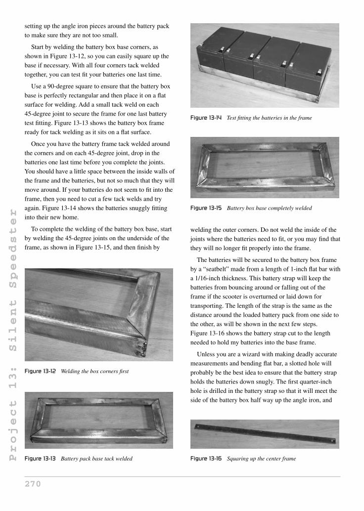
Project
13:
Silent
Speedster
setting up the angle iron pieces around the battery pack
to make sure they are not too small.
Start by welding the battery box base corners, as
shown in Figure 13-12, so you can easily square up the
base if necessary. With all four corners tack welded
together, you can test fit your batteries one last time.
Use a 90-degree square to ensure that the battery box
base is perfectly rectangular and then place it on a flat
surface for welding. Add a small tack weld on each
45-degree joint to secure the frame for one last battery
test fitting. Figure 13-13 shows the battery box frame
ready for tack welding as it sits on a flat surface.
Once you have the battery frame tack welded around
the corners and on each 45-degree joint, drop in the
batteries one last time before you complete the joints.
You should have a little space between the inside walls of
the frame and the batteries, but not so much that they will
move around. If your batteries do not seem to fit into the
frame, then you need to cut a few tack welds and try
again. Figure 13-14 shows the batteries snuggly fitting
into their new home.
To complete the welding of the battery box base, start
by welding the 45-degree joints on the underside of the
frame, as shown in Figure 13-15, and then finish by
Figure 13-12 Welding the box corners first
Figure 13-13 Battery pack base tack welded
Figure 13-14 Test fitting the batteries in the frame
Figure 13-15 Battery box base completely welded
welding the outer corners. Do not weld the inside of the
joints where the batteries need to fit, or you may find that
they will no longer fit properly into the frame.
The batteries will be secured to the battery box frame
by a “seatbelt” made from a length of 1-inch flat bar with
a 1/16-inch thickness. This battery strap will keep the
batteries from bouncing around or falling out of the
frame if the scooter is overturned or laid down for
transporting. The length of the strap is the same as the
distance around the loaded battery pack from one side to
the other, as will be shown in the next few steps.
Figure 13-16 shows the battery strap cut to the length
needed to hold my batteries into the base frame.
Unless you are a wizard with making deadly accurate
measurements and bending flat bar, a slotted hole will
probably be the best idea to ensure that the battery strap
holds the batteries down snugly. The first quarter-inch
hole is drilled in the battery strap so that it will meet the
side of the battery box half way up the angle iron, and
Figure 13-16 Squaring up the center frame
270

Project
13:
Silent
Speedster
then a line is extended past the edge of each hole to the
bottom of the strap, as shown in Figure 13-17. The slot
can then be cut away by tracing along the line with your
grinder disc or by sawing it out with a hacksaw. The
battery strap will now have a half inch of adjustment to
help ensure that it holds the batteries firmly to the base
frame.
The battery strap is bent to fit around the battery
pack so that the slotted hole ends up on each side of the
pack, as shown in Figure 13-18. The strap does not
need to be perfect now, since the slotted hole will allow
you to adjust the tension of the strap around the battery
pack, ensuring that the batteries cannot move or
vibrate. The thin flat bar is easily bent by placing the
area to be bent in a vice and then working it with a
hammer.
The slotted hole should end up on the angle iron
frame, as shown in Figure 13-19. A nut will then be
welded to the angle iron frame so the strap can be
secured and adjusted by installing a bolt on each side.
With your batteries installed in the frame, place the bent
strap in place and then mark the center of the slotted hole
so you know where to weld the nut.
Figure 13-17 Making the slotted hole
Figure 13-18 Bending the strap to fit the battery pack
Figure 13-19 Placement of the slotted hole
Figure 13-20 shows how the 1/4 bolt holds the battery
strap in place. The 1/4 nut is welded directly to the angle
iron frame under the slotted hole, and then the bolt is
installed to hold it in place. You will likely need to cut
the bolt down to the correct length, as a standard bolt will
be too long, so this is another job for your cut-off disc.
The two main tubes that make up the Silent Speedster
frame are called the “front boom tube” and the “rear
boom tube.” The rear boom tube will carry the batteries
and join directly to the bottom bracket of the rear
triangle, and the front boom tube will join the head tube
to the rear boom tube. Both boom tubes are made from
1.5-inch mild steel square tubing with a 1/16-inch wall
thickness. This tubing can be ordered from any steel
supplier and is very easy to cut and weld. Steel suppliers
like to rate tubing wall thickness using a gauge number,
so 1/16 wall tubing will be called 16-gauge tubing, and
although there is a slight difference between the two,
your best bet is to tell them you want a length of 1.5-inch
square tubing with a wall thickness as close to .0625 of
Figure 13-20 Battery strap secured to the frame
271

Project
13:
Silent
Speedster
an inch (1/16) as you can get. Round tubing should be
avoided for this project, as it will be difficult to mount
the battery box properly and cut the required angles.
Figure 13-21 shows the two boom tubes after cutting.
The short tube is the rear boom tube and the longer one is
the front boom tube. The length of the rear boom tube is
based on the overall length of your battery box as
measured from end to end (with battery strap included),
and the front boom is initially cut to a length of
24 inches, and will be shortened later based on your head
tube and front fork position. If you are using 26-inch
wheels instead of 20-inch wheels, then make the initial
front boom at least 4 inches longer. The next drawing
shows how each tube will be cut.
Figure 13-22 shows how each of the two main boom
tubes needs to be cut. The rear boom tube (shorter tube)
runs parallel to the ground, and carries the battery box, so
it is cut to a length of the battery box as measured from
the top. The front boom tube (longer tube) is cut to an
initial length of 24 inches just to be safe, and will be cut
down later when fitting the head tube. If you are using
26-inch wheels instead of 20-inch wheels, then make the
front boom length 28 inches to compensate. One end of
each tube is cut to an angle of 32 degrees, so the resulting
angle between the tubes will be 116 degrees when they
are welded together. The calculation used is
(90 – 32) × 2.
Figure 13-21 Cutting the two frame boom tubes
Figure 13-22 Front and rear boom tube lengths
The two boom tubes will be welded together at the
ends with the 32-degree angle cut, so that the resulting
boom will create a 116-degree angle between the two
tubes. If you cut the two ends to 32 degrees, the angle
between the two tubes will be very close to 116 degrees
when you check it after tack welding the two tubes
together, as shown in Figure 13-23. A few degrees off
will not have much effect on the final design, but do try
to get it as close as you can, and make the tack weld with
the tubes lying on a flat surface so they are perfectly in
line. Two tack welds on each corner of the joint, as
shown in Figure 13-23, will secure the tubing for a final
angle check before you finish the welding.
Once you have the two boom tubes tack welded
together and the angle is close to 116 degrees between
them, you can complete the welding by starting with the
top and bottom of the joint, as shown in Figure 13-24.
This order of welding helps prevent side-to-side
distortion of the tubing from welding heat, which could
make the boom twisted. If you were to start welding on
the side of the joint, the two tubes would not be perfectly
in line, and could be out enough to show a visible flaw in
our final design. A good welder always thinks ahead, and
tries to work around heat distortion as much as possible.
Figure 13-23 Tack welding the boom tubes
Figure 13-24 Welding the boom tubes together
272

Project
13:
Silent
Speedster
The sides of the boom joint can be completed once the
top and bottom of the joint have been fully welded. Use
the same size of bead on each side so distortion is not
prominent on either side. Figure 13-25 shows the entire
boom joint fully welded and inspected for pinholes.
If you trust your welding, then you can go ahead and
clean up the joint flush with the tubing wall, as shown in
Figure 13-26. Avoid taking out too much metal or you
will weaken the joint. A small hill over the weld is much
better than a valley, and this process will not weaken the
joint if the welding was done properly. A poor weld may
not have proper penetration, so grinding the area flush
may actually weaken the joint. If you see holes or flux in
the joint after grinding the weld metal flush with the
tubing, then your welds may have been done too cold.
The welds shown in Figure 13-26 have been ground
clean using a sanding disc (flap disc) and an angle
grinder.
The head tube will be welded to the end of the front
boom (the longer tube), and the rear boom (shorter tube)
will be welded to the bottom bracket on the original
BMX rear triangle. To mate properly with the bottom
Figure 13-25 Side boom joint completed
Figure 13-26 Cleaning up the boom welds
bracket, the tubing must have a round fish-mouth cut
made in it, roughly the same diameter as the bottom
bracket shell. As shown in Figure 13-27, a round object
with the same diameter as the bottom bracket is used as a
guide to trace out a line to be cut from the rear boom
tube. Keep in mind that the cuts are made on the sides of
the rear boom tube, not the top and bottom where the
cuts for the head tube will be made.
The joint between the rear boom and the bottom
bracket should look like the one shown in Figure 13-28.
Keeping the gap to a minimum facilitates the welding
process and reduces warping as the weld metal cools.
Once you have the fish-mouth cut made in the end of
the rear boom, it is time to join the rear triangle to the
boom. The ground clearance needs to be set so that there
are 4 inches between the underside of the boom and the
ground. Install a wheel into the rear triangle and mock up
the frame, as shown in Figure 13-29. This is done so that
you know at what angle the rear triangle needs to be
welded to achieve the 4-inch ground clearance. This
process must be done with one of your wheels and a fully
inflated tire, in order to make sure that the final angle is
Figure 13-27 Making a cut for the bottom bracket
Figure 13-28 Checking the bottom bracket joint
273

Project
13:
Silent
Speedster
Figure 13-29 Setting the ground clearance
the same as this one. Normally, I do not like to weld a
frame in place like this, but it does make the process a lot
easier to simply drop a tack weld onto the bottom bracket
and boom joint right where it sits. Make sure the boom
tubing is in line with the rear wheel and rear triangle
before you make your first tack weld, and then recheck
this alignment.
The large tack weld shown in Figure 13-30 was done
as the frame was standing in place, as shown in the
previous photo. By making a large tack weld, you can
carefully handle the frame once the rear wheel is
removed, which will make it much easier to visually
inspect the boom and rear triangle for alignment from
several different angles. It should be possible to force the
rear triangle side to side a little bit if necessary, in order
to make it perfectly in line with the boom tubing.
If you are satisfied that the boom tubing and rear
triangle are in line, then you can add another large tack
weld on the underside of the bottom bracket and rear
boom joint to hold the two pieces together for one last
visual alignment check. When you are sure that things
are aligned, complete the weld on the underside of the
bottom bracket, as shown in Figure 13-31. Try to make
Figure 13-30 Boom and bottom bracket tack welded
Figure 13-31 Welding the lower boom joint
one continuous weld across the joint to minimize any
side-to-side distortion.
The top of the bottom bracket and boom joint can be
done once the underside has been completed. The sides
of the joint are done last, and should be done in the same
manner to ensure that one side does not flex any further
than the other. If you think the alignment of the rear
triangle and boom is off on one side, then weld the joint
on the same side you wish to pull the alignment. It is a
welders’ trick to use heat distortion to one’s advantage.
Figure 13-32 shows the completed bottom bracket and
rear boom joint, welded all the way around.
The frame may feel extremely sturdy after you
complete the welding between the bottom bracket and
the rear boom, but it is not strong enough to be used as it
is. The square tubing boom could easily support up to
250 pounds like it is, but the bottom bracket shell would
have to endure more stress than it could handle, and
would simply fold up over the first hard bump. For this
reason, the addition of a smaller top tube will give the
frame incredible strength, as well as offer protection and
support for the top of your battery pack. This top tube is
Figure 13-32 Boom and bottom bracket welding completed
274

Project
13:
Silent
Speedster
just a length of thin walled (1/16) 1-inch square or round
tubing that joins the top of the seat tube to the front
boom, as shown in Figure 13-33. The length of this tube
is completely dependent on the distance from one tube to
the other, so just measure across the distance and cut a
tube a few inches longer so you can work backwards. The
top tube runs perfectly parallel to the rear boom tube.
Figure 13-34 shows how the top tube will meet the
seat tube using another fish-mouth cut to keep gap
spacing to a minimum. This is why I recommended that
you start with a top tube a little longer than necessary, as
it is easy to grind a little bit out of the joint at a time and
work backwards until the tube fits perfectly. It is all too
easy to make a tube a quarter inch too short, which will
be a nightmare to weld in place due to the massive gap in
the joint.
The top tube runs parallel to the rear boom, so
whatever height is needed at the seat tube end should be
transferred along the entire length of the top tube right up
to the joint at the front boom. Once you have the
fish-mouth cut at the seat tube end of the top tube, you
can tack weld it in place or hold it there, while you mark
the point where the top tube needs to connect with the
front boom. I made a mark for the center of the top tube,
as shown in Figure 13-35.
Figure 13-33 Installing the top tube
Figure 13-34 Top tube and seat tube joint
Figure 13-35 Keeping the top tube parallel to the rear boom
Once you have the front boom mark made, weld the
top tube in place, as shown in Figure 13-36, and your
frame will be extremely solid and able to support a great
deal of weight. Although frame flex is not much of a
worry now, it is always good practice to start welding the
two sides of a joint that will cause the least amount of
flex. For this joint, it is the top and bottom again, just as
it was for the rest of the frame tubing.
Although I ended up welding a seat post directly to the
top of the seat tube, it still made sense to cap off the open
end of the tubing, as it no longer has a clamp and will not
need to have a seat post inserted into it ever again. You
have tons of room to create your own seating system for
the Silent Speedster, and you may not even use the seat
tube as a support, so capping off the open end is a good
idea to make the final product look a lot more
professional. A simple method of capping off an open
tube is to weld in a washer and then fill in its hole.
A little work with a sanding disc does wonders for the
once-open seat tube, as shown in Figure 13-38. Now dirt
and moisture can’t enter the bottom bracket if you decide
not to use the seat post mounting system shown later in
the plan.
Figure 13-36 Welding the top tube to the front boom
275

Project
13:
Silent
Speedster
Figure 13-37 Capping the top of the seat tube
Figure 13-38 Seat tube cap completed
Once you join the head tube to the rest of the frame,
you will be able to drop in your batteries and hit the
streets! OK, there is a bit more work to do, but once the
head tube is installed, you will have a rolling chassis, and
that is a significant milestone in any vehicle build. The
head tube needs to be installed so that the angle formed
between it and the ground is approximately 70 degrees, as
described in the following drawing. Note that 70 degrees
is a good head tube angle for a vehicle of this speed and
wheelbase, but if you know what you are doing, then you
may want to alter this angle slightly for a more relaxed,
or more responsive, ride. You will need to mock up the
frame one last time, keeping that 4-inch ground clearance
and making sure the rear boom is parallel to the ground,
as shown in Figure 13-39. The front wheel and head tube
are then held in place at 70 degrees so you can draw a
line on the top of the front boom for cutting. You should
leave 2 inches of clearance between the edge of the front
tire and the front boom for fender placement.
Shown in Figure 13-40 is the imaginary line that
extends through the head tube and makes the 70-degree
angle with the ground. The line may not extend through
the front forks as they probably have some rake, so just
Figure 13-39 Setting the 70-degree head tube angle
Figure 13-40 70-degree head tube angle
remember that it is the head tube angle that counts. To set
up this angle, I tape a long, straight stick to an adjustable
square and then place it on the ground once it is set at 70
degrees. The long stick will help you set the proper head
tube angle.
If you can’t seem to get your front wheel to stay in
place at the required 70-degree angle, then have a helper
trace the cut line as you hold the head tube against the
side of the front boom, as shown in Figure 13-41.
Remember that the fish-mouth cut will take up about half
Figure 13-41 Marking the line to cut the boom
276

Project
13:
Silent
Speedster
an inch, so add this to your cut line or simply trace the
line about a half inch past the head tube as it is held in
place. Your goal is to mount the head tube at 70 degrees,
and end up with 2 inches of clearance between the front
boom and the front tire.
The fish-mouth cut on the end of the front boom is
made just like the one for the bottom bracket earlier,
using a similar diameter tube or object as a guide when
tracing the line. A half-inch deep cut should be all that is
needed to cradle the head tube into the 1.5-inch square
tubing for a perfect fitting joint. Figure 13-42 shows the
boom tube after grinding out the half-inch deep head
tube fish-mouth cuts on the top and bottom of the
tubing.
After making the fish-mouth cuts, prop up the frame
again and drop in the head tube to make sure it is close to
the 70-degree angle. A degree in either direction will not
make a huge difference, but try to get it as close as
possible, grinding a little bit out at a time until the angle
is very close. Figure 13-43 shows the perfectly snug joint
Figure 13-42 Cutting the head tube fish-mouth
Figure 13-43 Checking the head tube angle
between the head tube and the top of the front boom, as
the head tube rests at the desired 70-degree angle.
When you have the head tube joint up to par, make a
single tack weld on the top of the joint, as
shown in Figure 13-44. I did this with the frame set up on
the ground, so I could examine the head tube alignment
from all angles, ensuring that the head tube is in line with
the rest of the frame. The head tube should be parallel
with the seat tube and rear wheel. You can work the head
tube side to side a slight bit if it is necessary, and then
add another tack weld on the bottom of the joint to hold it
securely in place. Due to the fish-mouth cut, the
70-degree angle should already be good, but it doesn’t
hurt to check it one last time.
With a good tack weld on the top and bottom of the
head tube joint, the frame can now support itself as long
as you do not put any weight on it. This is your last
chance to check the head tube for alignment visually, and
make the needed adjustments by tapping it or forcing it
by hand. Look at your frame from all angles, making
sure both wheels are parallel when the front wheel is
pointing straight ahead. If everything looks good,
carefully remove the front forks and rear wheel so you
can complete the frame welding on your workbench.
As you have probably guessed, start by welding the top
and bottom of the head tube joint and then move on to
complete both sides. I like to drop in an old pair of head
tube cups, as shown in Figure 13-46, so that you keep the
head tube as round as possible, as the heat from welding
tries to distort it. Avoid any grinding of this weld, as it is
very strength-critical and should be as strong as possible.
Now you have a rolling frame that supports weight
without any problem, so drop in a set of handlebars and
you can safely handle the bike and sit on the frame.
Figure 13-44 Tack welding the head tube in place
277

Project
13:
Silent
Speedster
Figure 13-45 Head tube alignment final check
Figure 13-46 Completing the head tube welding
There are so many seating options that can make this
scooter into a multitude of different vehicles, each with a
different look and feel. You could go for the stand-up
scooter look and simply bolt on a pair of BMX foot pegs
to the side of the frame, or how about a sideboard-style
plank? For the sit-down scooter, you could add a nice
fishing boat seat, or make your own seat system,
complete with shock absorber and luggage compartment.
I decided to use the simplest bicycle-style seating
method, since it recycled some of the leftover bicycle
parts, and would cost almost nothing.
No matter what type of seat you choose, you have to
decide where your butt is going to live on the scooter by
trial and error. I found that the bucket placed near the rear
of the frame shown in Figure 13-47 was just perfect for
my size and sitting style, so I used that as a guide. When
choosing a sitting placement, keep in mind that the foot
pegs will be placed 6 inches from the ground, and that
you should be able to reach the handlebars without
stretching. Other than that, feel free to use your
imagination and make any kind of seat you like.
Because of the angle of the rear triangle, I knew that a
seat post would never be able to function the way it used
to, so the top of the seat tube was capped off. Of course,
Figure 13-47 Where shall I sit?
this doesn’t mean you can’t weld a seat post to the top of
the seat tube at whatever angle is necessary, and that is
exactly what I intended to do. I found a really ugly 1970s
exercise bike seat, a few seat stays from an old bicycle
frame, and the original seat post that came with the donor
BMX bike. The fat seat will be replaced with a nicer one,
and the curve in the BMX seat post was perfect for
placing that seat exactly where I wanted it, as per the
bucket test earlier.
The two support tubes made out of the old seat stays
are absolutely necessary in order to make your seat post
rigid, especially when it is placed at such a laidback
angle. A gusset would have also worked, but I wanted to
use up some of the scrap frame tubing I had lying in a
pile in the corner of the garage. When you are making
your seat mounts, be aware of your rear brake hardware,
making sure you are not placing any part in the way of
the correct operation of the rear brakes. Figure 13-49
shows how I made a very basic yet functional
bicycle-style seat mount for my Silent Speedster.
Now that you can sit and steer your scooter, it’s time to
add the muscle: the battery pack. Because of the simple
Figure 13-48 Recycling some old bicycle parts
278

Project
13:
Silent
Speedster
Figure 13-49 Installing the seat post
square tube frame, the battery pack can sit right on top of
the rear boom, and only needs four small tabs to secure it
in place. This system lets you have more than one battery
pack for a quick change if you plan on riding your
scooter non-stop, and do not want to wait overnight for
the battery pack to recharge. The battery box tabs are
shown in Figure 13-50, and are made from some scrap
1-inch flat bar cut into four 1-inch long segments with a
hole drilled in the center. Read ahead a bit to see how this
simple battery mounting system works.
The two lower battery pack tabs are welded to the
underside of the battery box frame, as shown in
Figure 13-51. The tabs are offset from the center of the
battery box frame so the battery pack ends up centered in
the frame when installed. Since the tabs press up against
nuts that have been welded to the side of the rear boom
tubing, take this into account when figuring out how far
to offset the battery pack tabs. The offset from center will
be 3/4 of an inch plus the thickness of the nut. Three
quarters of an inch is half the width of the 1.5-inch frame
tubing.
Figure 13-50 Installing the battery pack tabs
Figure 13-51 Lower battery pack tabs installed
Figure 13-52 shows how the tabs hold the battery pack
to the rear frame boom. Under each tab is a nut welded to
the frame, just like it was done earlier when you made
the battery box strap. Now that the lower battery tabs are
installed and the battery pack is held in place, you can
figure out the placement of the upper battery tabs.
The upper battery box mounting tabs work just like the
lower tabs, but another small length of flat bar will come
down from the top tube to place the nut in the correct
position. As shown in Figure 13-53, a marker is used to
Figure 13-52 Battery tab nuts and bolts in place
Figure 13-53 Installing the upper battery box tabs
279

Project
13:
Silent
Speedster
mark the point where the nut needs to be welded to the
flat bar that will hold it in place. Also, keep in mind that
the battery pack needs to slide out of one side of the
frame, so all nuts should face the same side of the frame.
Figure 13-54 shows the upper battery mounting tabs
installed and securely holding the battery pack in place.
Now the entire battery pack can be removed by taking
out the four bolts that hold it in place.
The rear of the upper battery tabs is shown in
Figure 13-55. The other side is the side that the battery
pack slides out of.
Foot pegs can be placed practically anywhere on the
scooter that you like, but as a rule, try to keep them
between 5 and 6 inches off the ground, so you can hit the
corners at full speed without having a foot peg strike the
ground. If you plan to do a lot of off-road riding, then
consider foldable pegs, as these are much safer when
obstacles such as trees and stumps may be thrown in the
mix. A very simple foot peg system using commonly
available bicycle parts can be made using some BMX
stunt pegs, a 4-inch length of 1/16 wall tubing, and a
high-grade bolt with a diameter of half an inch. These
Figure 13-54 Battery pack securely mounted
Figure 13-55 Upper battery tabs rear view
Figure 13-56 Foot peg hardware
parts are shown in Figure 13-56. Drill the 1/2 hole in the
BMX foot pegs, as they are pre-drilled and threaded for
bike axles.
Figure 13-57 shows how the foot peg hardware comes
together, using the long bolt to press both foot pegs
against the 3/3-inch tube that will then be welded onto the
scooter frame. A decent grade bolt is a must, as a soft
steel bolt could bend if you put too much weight on a
single peg.
Where you choose to install the foot pegs is up to you,
but don’t place them lower than 5 inches from the
ground, or you may not be able to navigate corners
without slowing down. At 6 inches from the ground, you
will be able to lean your scooter much farther than you
will ever have the nerve to do, unless motorcycle racing
is your hobby. I mounted the foot peg tube on the inside
of the front boom, as shown in Figure 13-58. Because the
front boom is at an angle, there is no interference with
the battery pack, and my feet end up in a nice relaxed
position, while still maintaining a 6-inch foot peg to
ground clearance.
The tube that holds the foot pegs and bolt is welded
directly to the frame, as shown in Figure 13-59.
In addition to making sure you do not place the pegs
lower than 5 inches to the ground, the only other thing
you need to do is ensure that the foot pegs are level, or
Figure 13-57 Foot peg hardware setup
280

Project
13:
Silent
Speedster
Figure 13-58 Foot pegs installed onto the frame
Figure 13-59 Foot peg mounting tube welded to the frame
perpendicular to the frame. Also, never choose the
battery box as a foot peg mounting place.
The last thing you need to do before painting the frame
is to cover up the unused open bottom bracket. This step
is actually optional, but honestly, after all that work, why
not finish the job, and cover that open hole which
obviously looks out of place? By covering the open
bottom bracket shell, you hide the last trace of that
home-built look, and cover up any places that moisture
or critters might want to take up residence. Any scrap
sheet metal can be used to cover the holes, and I simply
rough cut them out with the cut-off wheel from some
scrap sheet metal, as shown in Figure 13-60.
Once the two thin metal discs are cut out, they are tack
welded to the bottom bracket shell, as shown in
Figure 13-61.
Weld the two bottom bracket caps all the way around,
as shown in Figure 13-62. Due to the thin sheet metal
used, the welder can be turned down a great deal. At first,
the weld looks ugly and rough, but that will soon be fixed.
Figure 13-60 Making some bottom bracket caps
Figure 13-61 Capping off the open bottom bracket
Figure 13-62 Welding the caps in place
After a little work with the sanding disc, the bottom
bracket caps look perfect, hiding the last telltale sign that
the scooter frame might be home built. It’s the little
details that get noticed the most, especially by fellow
builders.
My hub motor kit came with a motor controller that
straps to the frame. I added the two small tabs, shown in
Figure 13-64, to keep the controller from wandering
around over time due to bumps and vibration. Thinking
ahead to small details like headlight mounting, fenders,
281

Project
13:
Silent
Speedster
Figure 13-63 Grinding the caps clean
Figure 13-64 Motor controller mounting tabs
and small accessories helps avoid the need to touch up
paint when you realize it later.
Waiting for paint and primer to dry is a boring
experience, but don’t lose patience and try to get your
trike on the road before the paint or primer has cured.
Often, primer needs a full day to dry, and paint will not
be ready for handling for at least two days. If you read
deep into the application directions, you might even see
that proper paint curing time is a week or more, so the
paint will be easily scratched if you are not careful. I
always use department store spray cans, and usually the
results are very good if I can avoid the urge to assemble a
wet-paint frame. Figure 13-65 shows the frame freshly
primed with the smaller parts painted and curing.
Paint also has a curing time that should be considered.
Often, you can handle the frame carefully after a day or
two of drying, but the paint will chip and scratch easily
until the curing period has passed, which is often more
than a month! I have been guilty of assembling a project
with tacky paint, but I do try not to rough handle any part
until at least a week has passed. Figure 13-66 shows the
Figure 13-65 Primed and curing
results of a few days of hard yet fun work in the garage: a
freshly painted scooter chassis ready for wiring and
cabling. Notice the ugly retro seat has been replaced by a
modern gel seat.
Take your time with the electrical system, minding
your positives and negatives. Always use proper
terminals, and always solder every connection. Crimp-on
connectors are for clowns! Seriously, crimped connectors
are failure prone and induce losses or electrical sparks
into your system as they work loose over time. Your
battery pack should have a connector that can be easily
unplugged for your charger, and all wiring should be the
proper gauge. If you are not certain what size of wire to
use, then look at the original wiring that came with your
hub motor kit, and use larger wire than that. A fuse
between your battery pack and the connector is also a
good idea, in case you short the connector or fry the
controller. If you have no idea whatsoever on how to
wire four batteries in series, then ask a friend—it’s no big
deal, and we all have to start someplace. Figure 13-67
shows my series wired battery pack using soldered
Figure 13-66 The basic rolling chassis painted
282

Project
13:
Silent
Speedster
Figure 13-67 Neatly wiring the electrical parts
spade connectors and an automotive connector
plug.
The right-hand side of your handlebars will probably
be quite busy, including a throttle, brake lever, and a
warning bell to get slow pokes out of your way.
Figure 13-68 shows my right-hand control cluster, with
all the goodies in close proximity. In my area, the law
requires a horn on all electric bicycles, and although I
was tempted to add a large car horn, I decided to be nice
to my battery pack and install a silly bell instead. “Ding!”
Look out, high speed scooter coming your way!
The rear brakes are of the higher quality cantilever
style, as shown in Figure 13-69. These brakes squeeze
directly against the rim for efficient grip unlike the
standard pull brakes, which work more like pliers. No
matter which brake system you have, always use new
cables, and make sure you test them intensively before
hitting the street. An electric vehicle like the Silent
Speedster is a lot heavier than a bicycle, and can outrun
Figure 13-68 Throttle, brake, and bell
Figure 13-69 Rear brake detail
many cyclists, so you certainly want good brakes. Never
force a cable into a tight bend, and make sure no cable
rubs on any moving part, especially when you turn the
front wheel from side to side.
My front brake is a side-pull, caliper-style brake
(Figure 13-70), which does work, but not nearly as good
as the type used on the rear of the scooter. Each brake
lever has an adjustment screw, and it should be screwed
all the way in when you initially set up the brakes. If the
brakes don’t grab hard enough, slowly turn the lever
adjustment screw counterclockwise to stiffen up the
brakes. A tiny bit of brake rubbing is OK, as long as you
can spin the wheel freely.
Figure 13-71 shows the Silent Speedster ready for
action. I have added a headlight, flashing rear light, and
will also be adding two fenders and a rear view mirror.
I will probably also make a simply battery box cover, but
for now, I enjoy showing off the internals when I get
Figure 13-70 Front brake detail
283
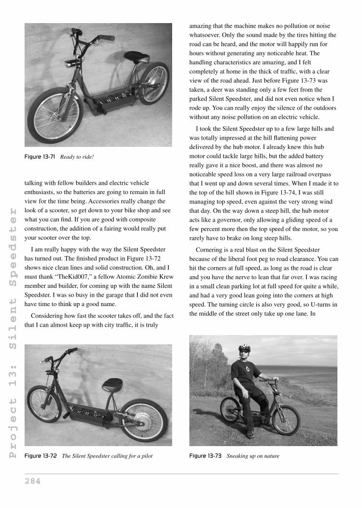
Project
13:
Silent
Speedster
Figure 13-71 Ready to ride!
talking with fellow builders and electric vehicle
enthusiasts, so the batteries are going to remain in full
view for the time being. Accessories really change the
look of a scooter, so get down to your bike shop and see
what you can find. If you are good with composite
construction, the addition of a fairing would really put
your scooter over the top.
I am really happy with the way the Silent Speedster
has turned out. The finished product in Figure 13-72
shows nice clean lines and solid construction. Oh, and I
must thank “TheKid007,” a fellow Atomic Zombie Krew
member and builder, for coming up with the name Silent
Speedster. I was so busy in the garage that I did not even
have time to think up a good name.
Considering how fast the scooter takes off, and the fact
that I can almost keep up with city traffic, it is truly
Figure 13-72 The Silent Speedster calling for a pilot
amazing that the machine makes no pollution or noise
whatsoever. Only the sound made by the tires hitting the
road can be heard, and the motor will happily run for
hours without generating any noticeable heat. The
handling characteristics are amazing, and I felt
completely at home in the thick of traffic, with a clear
view of the road ahead. Just before Figure 13-73 was
taken, a deer was standing only a few feet from the
parked Silent Speedster, and did not even notice when I
rode up. You can really enjoy the silence of the outdoors
without any noise pollution on an electric vehicle.
I took the Silent Speedster up to a few large hills and
was totally impressed at the hill flattening power
delivered by the hub motor. I already knew this hub
motor could tackle large hills, but the added battery
really gave it a nice boost, and there was almost no
noticeable speed loss on a very large railroad overpass
that I went up and down several times. When I made it to
the top of the hill shown in Figure 13-74, I was still
managing top speed, even against the very strong wind
that day. On the way down a steep hill, the hub motor
acts like a governor, only allowing a gliding speed of a
few percent more then the top speed of the motor, so you
rarely have to brake on long steep hills.
Cornering is a real blast on the Silent Speedster
because of the liberal foot peg to road clearance. You can
hit the corners at full speed, as long as the road is clear
and you have the nerve to lean that far over. I was racing
in a small clean parking lot at full speed for quite a while,
and had a very good lean going into the corners at high
speed. The turning circle is also very good, so U-turns in
the middle of the street only take up one lane. In
Figure 13-73 Sneaking up on nature
284

Project
13:
Silent
Speedster
Figure 13-74 Hill climbing is no problem
Figure 13-75 Speeding along on battery power
Figure 13-75, I am turning around at the top of an
overpass for yet another run up and down the hill to test
the ability of the hub motor.
Figure 13-76 Nothing but open road ahead!
I think the Silent Speedster is a perfect way to
commute distances without making any pollution, noise
or environmental impacts. You probably do not need a
license or insurance to ride a small electric bicycle like
this in many parts of the world, and in communities
where there are no existing electric bicycle laws, you
should be able to blend right in with typical
bicycle traffic. By adding a solar charger to your system,
you could have a maintenance-free form of transportation
that will cost you just pennies to run, and you can ride
proud knowing that you built it yourself. I hope you
enjoy riding your new electric vehicle, and urge others to
build their own version of this non-polluting alternative
transportation. Leave the gas-powered vehicles at home
and let the mighty electron move you!
285

Project
14:
Kids’
Electric
Trike
Project 14: Kids’ Electric Trike
Here is a fun, little, electric trike for the “young ’uns”
that can be built in a single evening from a pair of
children’s bicycles, a few bits of scrap tubing, and an old
stand-up electric scooter. Actually, this project is so
simple that you can make it out of practically any
battery-powered DC motor and any scrap bicycle parts
you may have lying around the shop. Since speed is
certainly not the goal here, even an old cordless drill will
make a fine power source for this vehicle, allowing your
kids to run around the yard for as long as the batteries
hold out. You can purchase one of those small, plastic,
electric kids’ cars at just about any toy store, but the
all-plastic construction and low-wattage motor may not
keep up with the kids’ demanding driving habits. If your
yard or park is not perfectly smooth and hill free, the
department store vehicle may wear out in a hurry, or
simply fail to traverse the terrain. By using a pair of kids’
bikes for the wheels and forks, this electric trike becomes
a high-quality vehicle, capable of driving on gravel, up
hills, through the mud, and even on the grass.
Since kids’ bikes come in many sizes, with wheels
measuring 10 inches, 12 inches, 14 inches, and 16 inches,
you should not have any problem scrounging up the parts
for this project by visiting the local dump or hitting the
yard sales around the neighborhood. The parts are really
not all that critical, but you will want the two front
wheels and two front forks to match, at least for size and
shape, since they will be placed side by side on the trike.
Figure 14-1 shows the basic parts that will be needed
in order to put the kids’ trike together. You will need
Figure 14-1 The basic parts needed for the trike
three bicycle wheels (two of which should match), three
front forks (two of which should match), one head tube
and bearing set to match one of the front forks, and some
type of DC motor that can power one of the wheels. I
chose an old stand-up electric scooter motor as the power
source because it could be placed against one of the trike
wheels to make the vehicle move, thus requiring no
transmission, gears or chains. These little stand-up
scooters are also plentiful at yard sales and scrap piles,
since it is often the frame that bends before the motor
fails. As shown in Figure 14-2, the entire rear end of the
electric scooter is cut from the frame, leaving only the
motor and the small drive wheel.
Figure 14-2 also shows what will become the front of
the trike: a front fork and matching head tube with all of
the included bearing hardware. This head tube actually
came from the electric scooter, and it just happened to fit
the kids’ bicycle fork perfectly. With all the bearing
Figure 14-2 The front fork and head tube
286Copyright © 2008 by The McGraw-Hill Companies, Inc. Click here for terms of use.

Project
14:
Kids’
Electric
Trike
hardware installed, the fork will spin freely and without
friction, which is a sure sign that all the hardware is
properly matched. If you take your front forks and head
tube from the same bicycle, then you will be certain that
all hardware matches.
To make the kids’ trike, you need two wheels and forks
for the rear and one front fork, wheel and head tube. For
this reason, the two rear wheels and forks should match,
and the front wheel can be whatever size you want. On
my trike, I decided to use three matching wheels since
they were easy to locate, and a front fork that was slightly
larger than the two at the rear. You will also notice that
all the wheels are actually front wheels, since there is no
drive chain needed. You could use a rear wheel if you
cannot locate three front wheels, but a little force will be
needed in order to widen the fork legs to take the axle.
Most cheap stand-up electric scooters have a 100 to
300-watt motor connected to a small rubber wheel, like
the wheel you would find on a road skate (Figure 14-4).
These motors will typically move the scooter at a speed
of 15 to 20 miles per hour when using a good 24-volt
power source. For use on a kids’ trike, I decided to use
only one large 12-volt battery, reducing the top speed to
about 10 miles per hour, but extending the run time by
many hours. Since the motor already turns the small
rubber drive wheel, all you need to do is let it rub against
one of the trike wheels, and you will have a transmission
system. Whatever speed the scooter would be capable of
will be the top speed of your trike, since there is no gear
reduction. As long as the scooter drive wheel is turning
the bicycle wheel by contact at the edge of each wheel,
there is a 1:1 gear ratio, so wheel size makes absolutely
no difference to the final speed of the vehicle.
Figure 14-3 Front and rear trike wheels
Figure 14-4 Scooter motor and drive wheel
Cut the stem from each of the rear forks just above the
crown, as shown in Figure 14-5. The cut area will be the
point at which you will attach your new frame tubing, as
this is the strongest area of the fork. If for some reason
your forks are not exactly the same, try to cut each stem
so that the distance from the axle to the cut area will
match on both forks.
Since I am building this kids’ trike from parts I had
lying around the garage, I simply placed the two rear
forks on the ground, and found a pair of 1-inch-diameter
square tubes that would create a triangular frame, as
shown in Figure 14-6. I think the square tubing came
from an old table I hacked up, but since the trike is only
going to hold the weight of a child, you don’t need to use
heavy tubing. As for the size of the frame, simply have
your young pilot sit on a chair, and make some basic
measurements of how much room they will need in order
to sit comfortably between three wheels. I went for a
wheelbase about the same as the original bicycle, and a
Figure 14-5 Cutting the stem from the two rear forks
287

Project
14:
Kids’
Electric
Trike
Figure 14-6 Laying out the basic frame
width of about the same as the wheelbase, creating an
equilateral triangle footprint.
The basic triangular frame needs three tubes to hold it
together, one at the rear to join the two rear forks, and
two more tubes at the front to form a triangle between the
fork crown area and the head tube. Shown in Figure 14-7
is the tube that will join together the two rear forks,
creating the frame to whatever width you like. The
fish-mouth cut will make welding a breeze, and the tube
should be placed about half an inch from the end of the
fork leg tube so there is room to make a weld.
With the parts sitting on a flat surface, tack weld the
rear frame tube to the two rear forks, as shown in
Figure 14-8, so that the fork legs are at 90 degrees to the
rear frame tube. Because both forks are sitting on the
same flat surface, vertical wheel alignment will be
perfect, and as long as you get both forks running
parallel, horizontal wheel alignment will also be perfect.
If the two rear wheels are badly out of alignment, there
will be scrubbing on the road, which will decrease
Figure 14-7 Joining the two rear forks together
Figure 14-8 Welding the rear frame tube to the forks
battery run time, so try to get the wheels running as true
as possible.
Once you have completely welded the rear frame tube,
join the two rear forks tighter so that you can continue
the frame layout, adding the two front frame tubes that
will form the triangle, as shown in Figure 14-9. The two
front frame tubes will determine the wheelbase (length)
of your trike, which should be fairly close to the original
bicycle wheelbase, so that your pilot can reach the
handlebars comfortably. Also shown in Figure 14-9 is the
front head tube, which should be set at an angle to match
the angle at which it was installed on the original
bicycle frame. The joint between the head tube and the
two front frame tubes needs to be ground out to conform
to the head tube, but it is fine to simply rough cut the
tubes for now, as you will want to install the wheels in
order to figure out the correct head tube angle.
If you welded the head tube at 90 degrees to the front
frame tubing, then there is a good chance that you will
have the correct head tube angle, as can be seen in
Figure 14-10. To make sure, I installed all three wheels to
ensure that the head tube angle was almost the same as it
was on the original bicycle before hacking it to bits.
Since this is a slow-moving kids’ trike, head tube angle is
not a real concern, so just make your best guess. If it
looks right, then, dude, it probably is right! Now you can
Figure 14-9 Continuing the frame layout
288

Project
14:
Kids’
Electric
Trike
Figure 14-10 Figuring out the correct head tube angle.
finish all the frame welding to secure the main frame
triangle to the head tube and rear forks.
The biggest complaint when it comes to kids and their
electric vehicles is how fast the battery goes dead. On the
original stand-up scooter, you could barely go around the
block once before the battery was weak enough to slow
down the scooter. By using a much larger battery and
half the voltage, the new trike will run almost all day on
a single charge, and allow the vehicle to get up hills that
would normally exceed the smaller battery packs’
immediate discharge capacity. Sure, the large battery is
quite heavy, but that simply adds stability to the trike, so
it won’t tip over as three kids try to stand on it as they
roll over the curb. Another very important thing to note
about the battery shown in Figure 14-11 is that it is a Gel
Figure 14-11 A large, 32-amp-hour, 12-volt battery
cell, or non-spillable battery, which is a must for a kids’
vehicle, which could see all kinds of abuse you never
even thought of. Unlike a typical lead acid battery, this
battery will not leak any dangerous chemicals, so don’t
use any other type of battery.
The battery will live between the two rear forks, as
shown in Figure 14-12, supported by a few bits of flat bar
which have been welded to a base made of angle iron.
The battery box base should place the battery at least
4 inches from the ground, so it doesn’t bang on small
objects which may roll under the trike as your kids drive
it through hostile territory.
The drive motor can live just about anywhere on the
trike, on any one of the three wheels, but it stays neatly
out of sight when placed under one of the rear forks, as
shown in Figure 14-13. Use whatever means is necessary
in order to place the scooter’s drive wheel up against the
Figure 14-12 A simple angle iron battery box
Figure 14-13 Installing the motor
289

Project
14:
Kids’
Electric
Trike
trike’s wheel, so that there is a decent amount of friction
between the two wheels. Inflate the tire to the proper
pressure before you do this, and try to keep both the drive
wheel and trike wheel in line, so that useless friction is
avoided. There should be enough friction between the
two wheels that it takes a bit of force to make them slip,
but not so much that they are difficult to turn by hand.
The little scooter motor is not all that powerful, so a little
slipping off the start is better than so much friction that
your motor overheats and burns out. A nice smooth tire,
or at least minimal tread at the point of contact, is also a
good thing.
Figure 14-14 shows the drive motor and all three
wheels installed on the basic trike frame. If I hold up the
drive wheel and drop the motor wires across the battery,
the drive wheel hums along, and seems to power the trike
with a reasonable amount of force when it is on the
ground. Take note of which way the wheel turns
according to wire polarity, so you don’t end up with a
backwards moving vehicle after finalizing the wiring.
Yes, the scooter wheel must turn in the opposite direction
of the trike’s rear wheel, or counterclockwise, to move
forward.
A very simple footrest can be made with a piece of
bent tubing, or a pair of conduit elbows welded together,
as shown in Figure 14-15. Again, I try to use up whatever
bits of scrap tubing are lying around the garage, so feel
free to experiment with whatever footrest designs you
think will work.
The seat will be placed over the battery, helping
protect the wiring, and keeping meddling hands out of
the electrical bits. Using some 3/3 tubing, or whatever
scraps you have in the junk pile, make a basic seat frame,
like the one shown in Figure 14-16, that can be welded to
Figure 14-14 Drive motor installed
Figure 14-15 A place to rest those lazy feet
Figure 14-16 Making a seat frame
the frame, allowing the seat to cover the battery yet also
allowing for the removal of the battery. An old kitchen
chair with metal legs is a good source of metal for the
seat frame as well as the seat cushion.
There is nothing critical about the seat frame, other
than allowing a comfortable sitting position and easy
removal of the battery for charging or swapping. The
simple seat frame shown in Figure 14-17 allows the
battery to drop into the battery box from the front of the
trike once the seat cover has been removed.
Once you finish up all the welds and paint your trike,
your young pilot will be able to hit the trails on a
long-running, environmentally friendly vehicle. Of
course, you have to do a bit of electrical wiring first in
order to transfer electrical power from the battery to the
motor, but since it is a simple matter of adding a switch
between the two, there is no need for a circuit diagram. If
your scooter came with a throttle switch like mine did,
then simply install the electrical system exactly the way
290

Project
14:
Kids’
Electric
Trike
Figure 14-17 Installing the seat frame
it was on the scooter. If you have no throttle switch, then
find a contact switch that can handle your motor’s power
(10 to 30 amps typically), and you are ready to roll. I also
added a front pull brake to the completed trike shown in
Figure 14-18, although it was probably not really
necessary due to the limited top speed, and the fact that it
stops moving within a few feet once the throttle is off.
The completed kids’ electric trike runs for many fun
hours on a single battery charge, and can take the abuse
that a young pilot can inflict without any problems. Top
speed is limited to a kid-safe level due to the lower
voltage, and even if the trike stalls, the motor will not
burn out because there is a limited amount of slip in the
friction drive. Figure 14-19 shows the brave test pilot,
Dylan Lange, putting the trike through its paces. Oh, and
yes, the trike can also move a fully grown kid around, as
I have found out!
Figure 14-18 Ready to ride!
Figure 14-19 Rollin’, rollin’, rollin’
291

This page intentionally left blank

Conclusion
Well, there you have it, folks! We took a pile of recycled
bicycle parts, some scrap tubing, a few basic tools, and
carved out an entire fleet of unique and functional
vehicles. This hobby is something that anyone can enjoy
without spending a lot of money or needing an
engineering degree. If you can imagine a new kind of
human-powered or electric vehicle, then chances are you
will be able to build it with a little effort. Builders like
you have picked up that welding torch and made bicycles
that fly, float, and even reach speeds beyond the posted
highway limits. Once you get the basic skills and get past
that first build, you will be hooked forever, always
modifying or improving your cool inventions. Inventing
mechanical devices is an art much like painting.
Your workbench is the canvas, the welder is the brush,
and that pile of junk in the corner of your garage is a
wonderful palette of paint. Don’t be afraid to set your
imagination free and alter the designs presented here to
suit your own needs. Mix and match projects, change
dimensions, or simply use the plan as a general guide to
build something altogether different—a little
improvization is what makes a true garage hacker shine.
Thanks for your support, and we hope to see your
work displayed in our forum and online gallery. If you
would like to connect with other fellow garage hackers to
share ideas, discuss your own projects, or seek help on
some of the vehicles presented here, then log on to
www.atomiczombie.com and say Hi.
Well, we’re off to the garage now where half a dozen
unfinished mechanical monsters are waiting for me to
help them come alive. There will be sparks, smoke,
grinding, hammering, and a lot of sweat, but eventually
that garage door will creak open once again, and who
knows what might roll out this time!
Cheers and happy building!
Brad and Kat
The AtomicZombie Krew
293Copyright © 2008 by The McGraw-Hill Companies, Inc. Click here for terms of use.

This page intentionally left blank

Index
Aangle grinder, 11–13, 16–17, 156, 273angle grinder discs, 11, 243–44Atomic Zombie web site, 20, 97–98, 113axle
alignment, 32, 109–10, 225characteristics, 176construction, 21–22crank, 7hub, 32, 63, 107mounting, 177–78, 226, 110, 112–13, 115rear, 5–6, 29, 44, 106, 108, 110, 133, 135, 151, 176–77, 197,
218, 230, 236spacers, 227
Bbackrest, 45, 49, 90–91, 94, 151–52, 164, 165, 168ball joints, 83–85, 121–22, 130–31, 151battery
charger for, 210, 245, 264discharge capacity, 212, 238, 289GEL, 210, 244, 268–69, 289rating, 209, 245, 269types, 210
battery box, 210–11, 244–45, 246–47, 269–70, 289bearing
alignment, 31bolts, 31, 141cup, 11orientation, 36, 188pillow block, 27, 30–31, 108–10, 134, 142–43race, 9, 34, 64, 121–22, 172, 182, 187, 218repacking, 198replacement, 182
bearing mounting plates, 214, 217, 224–26bicycle
discarded, 1, 11electric (see Kid’s Electric Trike; LongRanger Scooter;
Sparky Minibike)exercise, 53frame (see frame)front components, 2–3 (see also brake: levers; gooseneck;
shifters)kid’s, 25, 42, 57, 60, 146, 175, 189, 286–88load carrying, 3, 98, 179mountain, 2–3, 12, 34, 44, 57, 62, 126–28, 218,
242–43, 262rear components, 3–5recumbent (see StreetFox Tadpole Trike)trailer pulling, 98, 141, 179, 264upper-body-powered, 175
bicycle shops, 25boom tube
bottom bracket, 150front, 271–72main, 73, 75, 101–2, 272rear, 271–73, 275steering, 160–61
bottom bracketalignment, 188adjustable, 62, 85, 87–88, 125, 127, 149–50disassembly, 11, 124–25hardware, 11installation, 40, 85–86, 125–27, 186–88, 204, 273recycling, 39sizes, 124three-piece, 39, 187
brakearm, 4, 5, 81–82, 171, 172, 194caliper, 4, 80–81, 92, 171, 283cantilever, 3–4, 267, 283coaster, 42, 43, 55–56, 171–72, 175–76, 194, 206
(see also hub: coaster brake)design, 3disk, 100, 108, 139–43levers, 2, 92–93, 96, 140, 238 240, 283pull, 240, 261, 283, 291regenerative, 239, 260studs, 4, 5, 12, 261, 267support arms, 80–83
Ccable routing, 95, 145cable splitter, 92cantilever brakes, 3–4, 267, 283chain
basic design, 4drive side, 189, 191guard, 56, 153, 196–97,joining, 135, 193oiling, 196removal, 5–6return side, 189, 193rings, 4routing, 88, 132, 136, 150stays, 4–5, 12, 157–60tensioner, 5, 191–93, 204–5, 231 (see also chain
idler pulley)chain idler pulley, 88–89, 91–92, 132–33, 150, 190,
204, 231chain tool, 44–45, 89, 169chipping hammer, 13, 121chrome, 19, 46, 239, 266
295Copyright © 2008 by The McGraw-Hill Companies, Inc. Click here for terms of use.

Index
connecting rods, 83, 130contactor switch, 237–38control arms, 41, 82–84, 121–22, 129–30, 151control rod, 83–84, 130–31crank arm, 4, 6–8, 39, 43, 116, 119, 131, 165, 187,
189, 198crank set, 4, 7, 39, 124, 186–87, 189crash pad bar, 59
DDeltaWolf Racing Trike, 21
axle alignment for, 109–10brakes, 100, 139–41center of gravity in, 100chain, 132, 135–36completed, 144–45drive wheel, 100frame, 99, 101, 117gooseneck, 127handlebars, 128–29headrest, 137head tube, 119–20hub flanges, 107–8, 111–12neck rest, 137–38painting, 141–42seat fabrication, 141seat tube, 100–2spoke installation, 113–16steering system, 120–24, 130–31
derailleuradjustment, 96front, 4, 125–26mounting peg, 1356rear, 5–6, 136, 191–92tube, 86, 126
down tubebasic design, 3, 12, 40fabrication, 53, 147–48, 214–16, 267extension, 53
drill bits, 20–21, 24dropouts
front, 3, 66, 107, 177, 191, 219, 229, 253
Eelbow guards, 138–39electric motor
amperage ratings, 209batteries for (see battery)hub, 250–51, 263, 265, 268minimum run time for, 209–10mounting, 229–30voltage, 210watts, 209
electric motor speed controller, 208, 233, 237–39, 241, 250,263, 281
exercise bike, 53eye protection, 13
Ffenders, 56, 169–70, 208, 216, 234–35, 283foot pegs and foot rests, 196, 200–1, 203–4, 236–37, 260, 263,
280–81, 290fork
angle, 38, 164 (see also head tube: angle)bearings, 2, 9, 11, 129, 173, 182crowns, 64–65front (see front fork)rake, 38, 215rear forks, 287–89widening, 158
fork stembasic design, 2, 201gooseneck and, 2, 8, 127, 131, 185head tube and, 34, 53, 63, 77, 117, 157, 182, 218,installation, 35–36, 41, 54–55, 64, 67–68, 82–83, 121–23,
201, 218–19frame
alignment, 109, 161, 166–67, 248fabrication, 29–34, 41, 58–59, 99, 101, 117, 213–23, 157–63,
164–65, 178–81, 185, 247–50, 288–89jig, 77mono boom, 62rise, 33single-speed, 51–52suspension (see suspension)See also specific frame components
freehub, 100, 114, 132–36, 143front arm tubes, 72–76front control arms, 41front fork
alignment, 36, 38, 119basic design, 2–3, 286control arm, 129fabrication and installation, 35, 37, 42, 55, 129, 179, 217,
220, 226–27rake, 215removal, 9, 34, 146, 249, 277sizes, 3, 35, 117, 182, 268, 286springer, 36, 227tree plates, 219–20triple-tree, 3, 41, 55, 218–19widening, 158
front wheelalignment, 226–27, 249axle, 53–54basic design, 3brakes, 80, 92, 194 (see also brake)choice, 51, 219, 243, 287installation, 3, 72, 74, 80, 84, 160–61, 183, 215, 226,removal, 5–6, 194suspension for, 37, 242–43 (see also suspension)
fuses, 239, 263, 282
Ggear ratio, 98, 124, 223–25, 240, 287gear reduction, 224, 265
296

Index
Gladiator Choppercar rims for, 16–19, 24completed, 16, 49–51frame, 29–34, 41handlebars, 46hub flanges, 19–20painting, 47parts for, 16pillow block bearings in, 27, 31seating, 48–49suspension, 36–38, 47wheel building for, 24–26
gooseneckbasic design, 2, 89bolt, 8, 173, 186, 188clamp, 8, 90, 127extension tube, 128, 185–86, 188fabrication, 90, 127–28, 152, 185–86forkstem and, 2handlebars and, 7, 120, 131, 152sizes, 2, 9stem, 9, 41, 89–90, 128, 152, 186,
grindercutoff wheel for, 17disks for, 31, 170, 243–44technique, 244, 267
gussetframe, 181–82, 223suspension, 2under seat, 105–6
Hhandcycles. See bicycle: upper-body-powered; UCan2
HandCyclehand drill, 16–17, 20, 33, 66, 107–8, 177, 180handgrips, 8, 129, 198handlebar(s)
basic design, 2, 36clamp, 7, 128fabrication, 33, 46, 60, 90–91, 128–29, 152handgrips, 198mounting, 36, 45–46, 54, 57, 75, 90, 121, 127–29, 173, 228
headrest, 45, 64, 91, 137, 143head tube
alignment, 77, 120, 147, 184, 222, 277–28angle, 35, 74, 76–77, 119, 122–23, 184, 221, 243,
276–78, 289basic design, 2choppers and, 39cups, 9–10, 121, 277cutting, 34, 157steering, 120–23welding, 38–39, 76, 147, 165, 202, 223, 250, 273, 288
helmet, 13, 137–38, 199hole saw, 219horsepower, 208–9, 238hub
axles, 24, 62–63, 106, 113, 144coaster brake, 42, 43, 55–56, 171–72, 175–76, 194, 206
flange, 19–23, 107–8, 110–13, 139front, 3, 35, 37, 73, 183, 251remote coaster, 42–44spoke holes in, 3, 20–24, 107–8, 116wheelchair, 175
hub motor, 242, 244–45, 250–51, 253–54, 260, 263–66, 268–69,281–82, 284–85
Iidler pulley. See chain idler pulley
KKid’s Electric Trike
batteries for, 289battery box, 289brakes, 291completed, 291footrest, 290frame, 288–89head tube, 288–89scooter motor for, 287, 289seat, 290–91wheels for, 287
Kyoto Cruiser, 21
Llights, 55, 283Little Warrior Trike
completed, 153frame, 146–49handlebars, 152seat, 151–52steering, 151
load carrying, 3, 98, 179LongRanger Scooter
battery box, 246–47brakes, 260–61completed, 242, 264footpegs, 260frame, 247–50head tube, 243, 250hub motor for, 250–51, 263painting, 261seating, 258–59, 262suspension, 251–57wiring, 263
MMarauder, 124, 129, 137, 142metal oxide silicon field effect transistors
(MOSFETTs), 240motor speed controller, 208, 233, 237–39, 241, 250,
263, 281
297

Index
Nneck rest, 45, 137–38, 141
OOld Skool Attitude
brakes, 55completed, 51, 56forks for, 53–55paint, 55–56seating, 55
OverKill chopper, 17, 28–29, 33
Ppaint
“Gypsy chrome”, 55–56primer, 24, 47, 95, 141, 198, 239, 261, 282spray, 47, 141, 198, 239, 261, 282
pedals, 4, 67, 116, 159, 165, 185, 204pillow block bearings, 27, 30–31, 108–10, 134,
142–43projects. See DeltaWolf Racing Trike; Gladiator Chopper;
Kid’s Electric Trike; LittleWarrior Trike; LongRangerScooter; Old Skool Attitude; Silent Speedster; SkyStyleTallbike; Sparky Minibike; SpinCycle Stunt Trike;StreetFox Tadpole Trike; UCan2 HandCycle;WhipperSnapper
Rrear axle. See axle: rearrear dropout, 3–5, 12, 44, 135, 150, 157, 169,
252–53,rear freewheel, 5rear suspension, 10–11, 62, 70, 251, 256–57rear triangle, 4, 5, 10, 62, 70–72, 266–68, 271,
273–74, 278rear wheel
alignment, 5, 31–32, 101, 109, 150, 178–79, 225,253, 288
braking, 43–44, 55, 139, 206building, 46coaster hub and, 43, 56, 206
recumbent bicycle. See StreetFox TadpoleTrike
rim(s)aluminum, 2, 26, 113, 266bicycle, 47brakes and, 5, 82, 92, 96, 266, 283building, 47, 115car, 16–19, 26freestyle, 25, 175–76measurement, 23painting, 17, 24, 47spokes (see spoke(s))
Ssafety switch, 239seat
angle, 70–71fabrication, 93–94, 168–69, 171, 236, 258–59, 262location, 45–46, 89mounting, 89, 91, 141, 167–69, 233–34, 259–60,
290–91removal, 9upholstery, 93–94, 171, 236, 262
seat belt, 194seat post, 9, 279seat stays, 4–5, 12, 149, 195, 259, 267, 278seat tube
alignment, 52, 59basic design, 3, 40, 70clamp, 9, 12fabrication, 70–71, 100–102, 125, 151–52, 202installation, 71–72, 195, 202–3
shifters, 2, 95, 101–2, 129, 188Shimano-style freehub, 114, 133shock absorbers, 4, 242–43, 254–57, 278Silent Speedster, 265–85
batteries for, 268–69battery box, 269–70brakes, 283completed, 265, 284–85foot pegs, 280–81frame, 271–78ground clearance, 274head tube, 273, 276–78hub motor for, 265, 268, 281painting, 282range, 265seat, 275–76, 279speed, 266tires for, 266
SkyStyle Tallbikecompleted, 206footpegs, 201, 203–4headtube, 202mounting, 205–6planning, 200seat tube, 203
Sparky Minibikebatteries for, 211battery box, 211–12belt drive, 231–33brakes, 239–40chain drive for, 231completed, 241–42fenders, 234–35footpegs, 236–37frame, 213–23gear ratio, 224–25handlebars, 228head tube, 221motor speed controller for, 237, 241painting, 239
298

Index
seat, 234–36top speed, 208, 223
SpinCycle Stunt Trikebrakes, 171completed, 172–74fender, 169frame, 157–63, 164–65head tube, 165–66history, 156maneuvers with, 173–74seat, 167, 171steering, 159T-bar, 167
spoke(s)holes, 3, 20–24, 107–8, 116installation, 25–26, 113–14nipples, 24–29, 113numbers, 3, 23tightening, 27–28, 13, 1142
springs, 4, 10–11, 62, 70–72, 79–80, 256–57sprocket, 43–45, 158, 189, 204, 226, 231, 233,steering
Ackermann, 82–84, 151boom, 159–61center point, 67, 75control arms, 41, 82–85, 121–23, 125,
129–31, 151tadpole trikes and, 65–67, 75, 82–85testing, 84–85
StreetFox Tadpole Trike, 2, 62–97,axle mounting, 65–69backrest, 91braking, 80–81, 92chain, 88completed, 62, 95, 97forks, 63–65handlebars, 89head tube, 74, 76–78painting, 95pivot tube, 70seating, 70–72, 89, 93steering, 65–66, 75, 82–85suspension, 80
suspensiongussett, 3mounting, 80rear, 10–11, 62, 70, 251, 256–67shock absorbers, 4, 242–43, 254–57, 278spring, 4, 10–11, 62, 70–72, 79–80, 256–57springer fork, 36–37, 50swingarm, 69–70, 248, 251–57, 260–61, 263
Ttallbikes. See SkyStyle Tallbiketire
balloon, 56, 174, 227choice, 26, 28, 80, 116, 172, 176–77, 262, 290clearance, 81, 159, 164, 170, 216–17, 221,
252, 277
front, 5, 38, 81, 159, 164–65, 172, 173, 176, 183, 219,243, 249, 276–77
inflation, 29, 38, 68, 71, 116, 177, 183, 243, 266,252, 256
inner tube, 28–29installation, 28–29rear, 216–17, 228, 252scrub, 31, 67, 83–85, 99, 109width, 17, 23
tool(s)angle grinder, 11–13, 16–17, 180chain, 44–45, 89, 169chipping hammer, 13, 121drill bits, 20–21, 24eye protection, 13hand drill, 16–17hole saw, 219welder, 2, 12–13, 17, 33, 156, 180, 293welding helmet, 13
top tube, 3, 12, 52, 146–48, 208, 243–44, 267–68, 274–75, 279trailer pulling, 98, 141, 179, 264transmission, 42–44, 88, 100, 133, 136–37, 143, 195, 208, 224,
230–33, 287. See also individual componentstrike
advantages and disadvantages, 98elbow room, 99layout options, 98See also DeltaWolf Racing Trike; Kid’s Electric Trike; Little
Warrior Trike; StreetFox Tadpole Trike; UCan2 HandCycletruing stand, 27, 113, 142truss tubes, 102–3, 216
tubingbending, 33capping, 36, 46–47, 81, 87, 104–5, 199, 214–15, 239,
258–59, 275, 281electrical conduit (EMT), 29, 46, 159, 163, 213–14,
217–18, 225fish-mouth cut style, 30, 69, 75, 77–78, 118, 123, 148–49,
214, 273,276–77, 288gauge, 69, 98, 130, 156square, 35, 45, 69–70, 72, 80, 89, 98, 101, 103–5, 117, 156,
162–63, 177–81, 247–49, 271, 274, 287
UUCan2 HandCycle, 175–99
brake, 193–94completed, 199footrest, 196frame, 178–81, 185head tube, 182painting, 198–99seat, 195–96tires for, 176–77
upholstery, 93–94, 171, 236, 262
VV-belt idler pulley, 88, 92, 150, 190, 204
299

Index
Wwelder, 2, 12–13, 17, 33, 156, 180, 293welding helmet, 13welding technique, 39, 182–83, 268, 273wheel
alignment, 32, 179, 226–27, 254, 288basic design, 3building, 24–29, 113–16, 142, 146cambered, 175caster, 156, 161–63, 166–67, 170, 174front (see front wheel)rear (see rear wheel)
rims (see rim(s))rotation rate, 224shopping cart, 156, 162size, 3, 63, 287spokes (see spoke(s))tire choice for (see tire: choice)
wheelie(s), 56–57, 200, 202, 210, 212, 231, 234, 238, 242,251, 264, 266
wheel truing stand, 113WhipperSnapper
completed, 57, 60frame, 58–59handlebars, 60painting, 59
300