Bike Manual OMLemond04
60
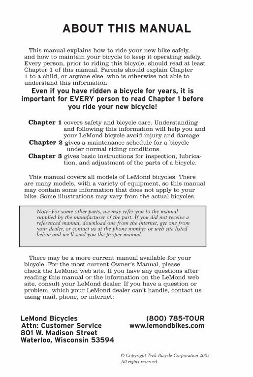
ABOUT THIS MANUAL This manual explains how to ride your new bike safely, and how to maintain your bicycle to keep it operating safely. Every person, prior to riding this bicycle, should read at least Chapter 1 of this manual. Parents should explain Chapter 1 to a child, or anyone else, who is otherwise not able to understand this information. Even if you have ridden a bicycle for years, it is important for EVERY person to read Chapter 1 before you ride your new bicycle! Chapter 1 covers safety and bicycle care. Understanding and following this information will help you and your LeMond bicycle avoid injury and damage. Chapter 2 gives a maintenance schedule for a bicycle under normal riding conditions. Chapter 3 gives basic instructions for inspection, lubrica- tion, and adjustment of the parts of a bicycle. This manual covers all models of LeMond bicycles. There are many models, with a variety of equipment, so this manual may contain some information that does not apply to your bike. Some illustrations may vary from the actual bicycles. There may be a more current manual available for your bicycle. For the most current Owner’s Manual, please check the LeMond web site. If you have any questions after reading this manual or the information on the LeMond web site, consult your LeMond dealer. If you have a question or problem, which your LeMond dealer can’t handle, contact us using mail, phone, or internet: LeMond Bicycles (800) 785-TOUR Attn: Customer Service www.lemondbikes.com 801 W. Madison Street Waterloo, Wisconsin 53594 Note: For some other parts, we may refer you to the manual supplied by the manufacturer of the part. If you did not receive a referenced manual, download one from the internet, get one from your dealer, or contact us at the phone number or web site listed below and we’ll send you the proper manual. © Copyright Trek Bicycle Corporation 2003 All rights reserved
-
Upload
imperialstar12535 -
Category
Documents
-
view
303 -
download
1
Transcript of Bike Manual OMLemond04
ABOUT THIS MANUAL
This manual explains how to ride your new bike safely, and how to maintain your bicycle to keep it operating safely. Every person, prior to riding this bicycle, should read at least Chapter 1 of this manual. Parents should explain Chapter 1 to a child, or anyone else, who is otherwise not able to understand this information.
Even if you have ridden a bicycle for years, it is important for EVERY person to read Chapter 1 before
you ride your new bicycle!
Chapter 1 covers safety and bicycle care. Understanding and following this information will help you and your LeMond bicycle avoid injury and damage.
Chapter 2 gives a maintenance schedule for a bicycle under normal riding conditions.Chapter 3 gives basic instructions for inspection, lubrica-
tion, and adjustment of the parts of a bicycle.
This manual covers all models of LeMond bicycles. There are many models, with a variety of equipment, so this manual may contain some information that does not apply to your bike. Some illustrations may vary from the actual bicycles.
There may be a more current manual available for your bicycle. For the most current Owner’s Manual, please check the LeMond web site. If you have any questions after reading this manual or the information on the LeMond web site, consult your LeMond dealer. If you have a question or problem, which your LeMond dealer can’t handle, contact us using mail, phone, or internet:
LeMond Bicycles (800) 785-TOUR Attn: Customer Service www.lemondbikes.com 801 W. Madison Street Waterloo, Wisconsin 53594
Note: For some other parts, we may refer you to the manual supplied by the manufacturer of the part. If you did not receive a referenced manual, download one from the internet, get one from your dealer, or contact us at the phone number or web site listed below and we’ll send you the proper manual.
© Copyright Trek Bicycle Corporation 2003All rights reserved
ii iii
YOUR LEMOND BICYCLE
Your bicycle: Model Name or No. Color Size
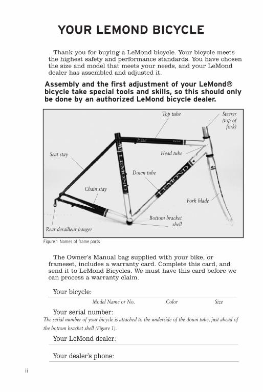
Your serial number: The serial number of your bicycle is attached to the underside of the down tube, just ahead of
the bottom bracket shell (Figure 1).
Your LeMond dealer: Your dealer's phone:
Thank you for buying a LeMond bicycle. Your bicycle meets the highest safety and performance standards. You have chosen the size and model that meets your needs, and your LeMond dealer has assembled and adjusted it.
Assembly and the first adjustment of your LeMond® bicycle take special tools and skills, so this should only be done by an authorized LeMond bicycle dealer.
The Owner’s Manual bag supplied with your bike, or frameset, includes a warranty card. Complete this card, and send it to LeMond Bicycles. We must have this card before we can process a warranty claim.
Figure 1 Names of frame parts
Seat stay
Rear derailleur hanger
Bottom bracket shell
Chain stay
Top tube
Head tube
Steerer (top of
fork)
Fork blade
Down tube
ii iii
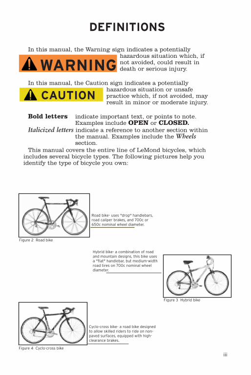
In this manual, the Warning sign indicates a potentially hazardous situation which, if not avoided, could result in death or serious injury.
In this manual, the Caution sign indicates a potentially hazardous situation or unsafe practice which, if not avoided, may result in minor or moderate injury.
Bold letters indicate important text, or points to note. Examples include OPEN or CLOSED.
Italicized letters indicate a reference to another section within the manual. Examples include the Wheels section.
This manual covers the entire line of LeMond bicycles, which includes several bicycle types. The following pictures help you identify the type of bicycle you own:
DEFINITIONS
WARNING
CAUTION
Road bike- uses "drop" handlebars, road caliper brakes, and 700c or 650c nominal wheel diameter.
Figure 2 Road bike
Cyclo-cross bike- a road bike designed to allow skilled riders to ride on non-paved surfaces, equipped with high-clearance brakes.
Figure 4 Cyclo-cross bike
Hybrid bike- a combination of road and mountain designs, this bike uses a "flat" handlebar, but medium-width road tires on 700c nominal wheel diameter.
Figure 3 Hybrid bike
iv v
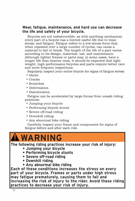
Wear, fatigue, maintenance, and hard use can decrease the life and safety of your bicycle.
Bicycles are not indestructible: as with anything mechanical, every part of a bicycle has a limited useful life due to wear, stress, and fatigue. Fatigue refers to a low-stress force that, when repeated over a large number of cycles, can cause a material to fail or break. The length of the life of a part varies according to its design, materials, use, and maintenance. Although lighter frames or parts may, in some cases, have a longer life than heavier ones, it should be expected that light weight, high performance bicycles and parts require better care and more frequent inspections.
Regularly inspect your entire bicycle for signs of fatigue stress:• Dents• Cracks• Scratches• Deformation• Discoloration Fatigue can be accelerated by large forces from unsafe riding
practices:• Jumping your bicycle• Performing bicycle stunts• Severe off-road riding• Downhill riding• Any abnormal bike riding Carefully inspect your frame and components for signs of
fatigue before and after each ride.
WARNINGThe following riding practices increase your risk of injury: • Jumping your bicycle • Performing bicycle stunts • Severe off-road riding • Downhill riding • Any abnormal bike riding Each of these conditions increases the stress on every part of your bicycle. Frames or parts under high stress may fatigue prematurely, causing them to fail and increasing the risk of injury to the rider. Avoid these riding practices to decrease your risk of injury.
iv v
TABLE OF CONTENTS
Chapter 1 Guide to Safe On-and-Off Road Operation
Make sure your bicycle fits you properly .......................... 1Know how your bicycle performs ................................... 1-2Before every ride: Check your bike ................................ 3-7During every ride: Ride safely. ..................................... 8-11Before, during, & after every ride: Take care of your bike............................................................ 12-14 Use your pedal system safely. .................................. 15-17
.
Chapter 2 Periodic MaintenancePeriodic maintenance schedule................................... 18-19Recommended tools for proper bicycle maintenance...... 19
Chapter 3 Inspection, Adjustment, and Lubrication Some maintenance and repair should only be performed by your LeMond dealer, as indicated in this manual.
A word about torque specifications ................................. 21Handlebars, bar-ends, and stem ................................. 22-24Seat and seatpost ........................................................ 25-27Drivetrain- pedals, crank, chain, and cassette ........... 22-30Shifting systems ......................................................... 31-35Headset and fork......................................................... 36-37Brake systems ............................................................. 38-42Wheels ......................................................................... 43-50Reflectors ......................................................................... 48Tire installation........................................................... 49-50Care of your frame or fork.......................................... 51-52LeMond Bicycles limited warranty .................................. 54
IMPORTANT! Read this chapter before you ride
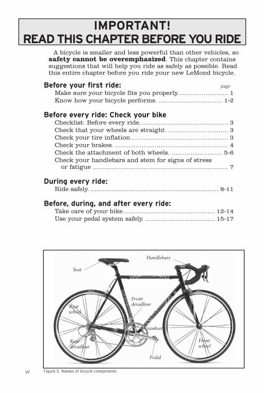
vi 1CHAPTER ONE Guide to Safe On-and-Off Road OperationFigure 5 Names of bicycle components
Seat
Handlebars
Front derailleur
Pedal
Crankset
Rear derailleur
Front wheel
Rear wheel
IMPORTANT! READ THIS CHAPTER BEFORE YOU RIDE
A bicycle is smaller and less powerful than other vehicles, so safety cannot be overemphasized. This chapter contains suggestions that will help you ride as safely as possible. Read this entire chapter before you ride your new LeMond bicycle.
Before your first ride: page
Make sure your bicycle fits you properly........................... 1Know how your bicycle performs. .................................. 1-2
Before every ride: Check your bikeChecklist: Before every ride............................................... 3Check that your wheels are straight. ................................ 3Check your tire inflation.................................................... 3Check your brakes. ............................................................ 4Check the attachment of both wheels. ........................... 5-6Check your handlebars and stem for signs of stress
or fatigue ........................................................................ 7
During every ride:Ride safely. .................................................................... 8-11
Before, during, and after every ride:Take care of your bike................................................. 12-14Use your pedal system safely. ..................................... 15-17
vi 1CHAPTER ONE Guide to Safe On-and-Off Road Operation
Make sure your bicycle fits you properly. Your LeMond dealer should fit you with the
proper size of bicycle.
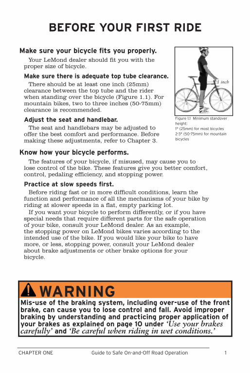
Make sure there is adequate top tube clearance.There should be at least one inch (25mm)
clearance between the top tube and the rider when standing over the bicycle (Figure 1.1). For mountain bikes, two to three inches (50-75mm) clearance is recommended.
Adjust the seat and handlebar.The seat and handlebars may be adjusted to
offer the best comfort and performance. Before making these adjustments, refer to Chapter 3.
Know how your bicycle performs.The features of your bicycle, if misused, may cause you to
lose control of the bike. These features give you better comfort, control, pedaling efficiency, and stopping power.
Practice at slow speeds first.Before riding fast or in more difficult conditions, learn the
function and performance of all the mechanisms of your bike by riding at slower speeds in a flat, empty parking lot.
If you want your bicycle to perform differently, or if you have special needs that require different parts for the safe operation of your bike, consult your LeMond dealer. As an example, the stopping power on LeMond bikes varies according to the intended use of the bike. If you would like your bike to have more, or less, stopping power, consult your LeMond dealer about brake adjustments or other brake options for your bicycle.
BEFORE YOUR FIRST RIDE
Figure 1.1 Minimum standover height:1" (25mm) for most bicycles2-3" (50-75mm) for mountain bicycles
1 inch
WARNINGMis-use of the braking system, including over-use of the front brake, can cause you to lose control and fall. Avoid improper braking by understanding and practicing proper application of your brakes as explained on page 10 under ‘Use your brakes carefully’ and ‘Be careful when riding in wet conditions.’
2 3CHAPTER ONE Guide to Safe On-and-Off Road Operation
Avoid shimmy or front-wheel wobble.In very rare cases some riders, such as heavier riders on
larger bikes, may experience a “shimmy” or “harmonic oscilla-tion” or “frame vibration” at certain speeds. Experts disagree on what can cause a shimmy, but some believe it may be caused by a loose headset, improper spoke tension, or frame alignment. Riding “no-hands,” or front wheel impact, are among other possible causes. If you believe you are experiencing a shimmy, slow down immediately and take your bicycle directly to a LeMond dealer for inspection and repair.
Make sure accessories are compatible and safe.To make your bicycle more personally useful, you may
choose to change parts or add accessories. Not all accessories are compatible or safe. If you are unsure whether a part is appropriate or safe, consult your LeMond dealer.
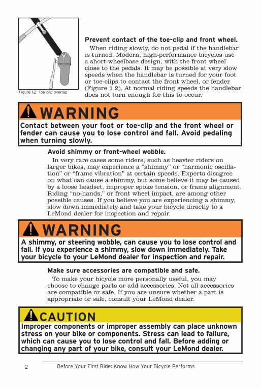
Prevent contact of the toe-clip and front wheel.When riding slowly, do not pedal if the handlebar
is turned. Modern, high-performance bicycles use a short-wheelbase design, with the front wheel close to the pedals. It may be possible at very slow speeds when the handlebar is turned for your foot or toe-clips to contact the front wheel, or fender (Figure 1.2). At normal riding speeds the handlebar does not turn enough for this to occur.
WARNINGA shimmy, or steering wobble, can cause you to lose control and fall. If you experience a shimmy, slow down immediately. Take your bicycle to your LeMond dealer for inspection and repair.
Before Your First Ride: Know How Your Bicycle Performs
Figure 1.2 Toe-clip overlap
WARNINGContact between your foot or toe-clip and the front wheel or fender can cause you to lose control and fall. Avoid pedaling when turning slowly.
CAUTIONImproper components or improper assembly can place unknown stress on your bike or components. Stress can lead to failure, which can cause you to lose control and fall. Before adding or changing any part of your bike, consult your LeMond dealer.
2 3CHAPTER ONE Guide to Safe On-and-Off Road Operation
Before each ride, check your bike and its components against the following checklist. The following information explains how to perform these checks. This is not a comprehensive maintenance program. If you are not certain if your bike has a problem, take your bike to your LeMond dealer for service.
Checklist: Before every ride
Check that your wheels are straight.
Check your tire inflation.
Check your brakes.
Check attachment of both wheels.
Check your handlebars and stem for signs of stress or fatigue.
Check that your wheels are straight.Spin each wheel and watch the rim as it
passes through the brake pads or the frame. If the rim wobbles, up and down or from side to side, take your bike to your LeMond dealer for service.
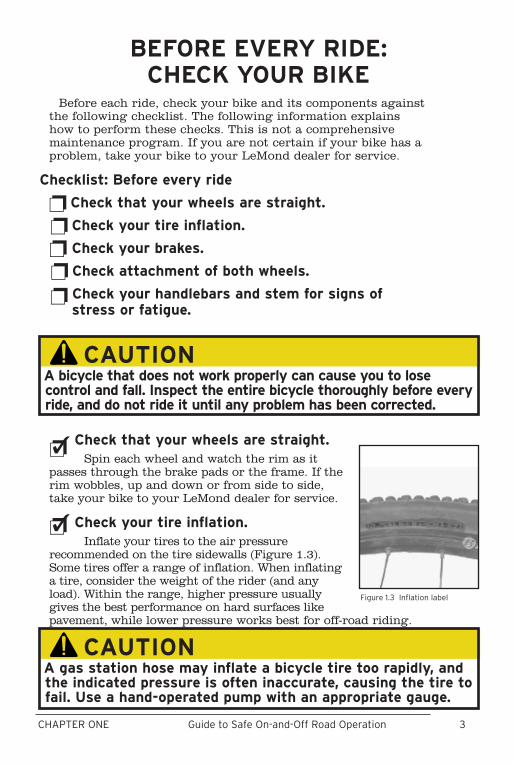
Check your tire inflation.Inflate your tires to the air pressure
recommended on the tire sidewalls (Figure 1.3). Some tires offer a range of inflation. When inflating a tire, consider the weight of the rider (and any load). Within the range, higher pressure usually gives the best performance on hard surfaces like pavement, while lower pressure works best for off-road riding.
BEFORE EVERY RIDE:CHECK YOUR BIKE
Figure 1.3 Inflation label
A gas station hose may inflate a bicycle tire too rapidly, and the indicated pressure is often inaccurate, causing the tire to fail. Use a hand-operated pump with an appropriate gauge.
CAUTION
A bicycle that does not work properly can cause you to lose control and fall. Inspect the entire bicycle thoroughly before every ride, and do not ride it until any problem has been corrected.
CAUTION

4 5CHAPTER ONE Guide to Safe On-and-Off Road Operation
Check your brakes.If your brakes do not pass inspection, refer to the Brake
Systems section of Chapter 3, or take your bicycle to your LeMond dealer for service.
Squeeze each brake lever toward the handlebar to make sure the brake moves freely and stops the bike. If the brake lever can be pulled to the handlebar, the brake is too loose. When the brakes are not applied, the brake pads should be 1 to 2mm from the rim. If the brake pads are too close to the rim, the brake is too tight. Brake pads should be aligned with the rim surface (Figure 1.4).
WARNINGIf your brakes are not working properly, you can lose control and fall. Inspect the brakes thoroughly before every ride, and do not ride the bicycle until any problem has been corrected.
Before Every Ride: Check Your Bike
Pad and rim should be parallel
Brake pad aligned with the
rim surface
Figure 1.4 Brake pad alignment
Direction of rim rotation
0.5 - 1 mm toe-in
4 5CHAPTER ONE Guide to Safe On-and-Off Road Operation
Check the attachment of both wheels.To be ridden safely, the wheels of your bicycle must
be firmly attached to the frame and fork. Bicycle wheels are attached by either threaded axle nuts or a quick-release, a lever-actuated wheel retention mechanism (Figure 1.6) that allows the wheel to be installed and removed without tools.
Quick-release adjustment and closureFor proper and safe adjustment of a quick-release,
read and follow these instructions carefully.
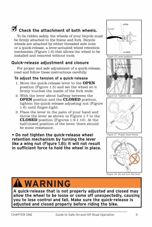
To adjust the tension of a quick-release1. Move the quick-release lever to the OPEN
position (Figure 1.5) and set the wheel so it firmly touches the inside of the fork ends.
2. With the lever about halfway between the OPEN position and the CLOSED position, tighten the quick-release adjusting nut (Figure 1.6) until finger-tight.
3. Place the lever in the palm of your hand and throw the lever as shown in Figure 1.7 to the CLOSED position (Figures 1.9-1.10). At the half-closed position of the lever, there should be some resistance.
• Do not tighten the quick-release wheel retention mechanism by turning the lever like a wing nut (Figure 1.8); it will not result in sufficient force to hold the wheel in place.
WARNINGA quick-release that is not properly adjusted and closed may allow the wheel to be loose or come off unexpectedly, causing you to lose control and fall. Make sure the quick-release is adjusted and closed properly before riding the bike.
����
������
Figure 1.7 Proper lever throw
Figure 1.6 Tighten nut
Quick-release adjusting nut
����
������
Figure 1.5 Lever positions
Lever
����
����
����
����
Figure 1.8 Do not turn the lever
6 7CHAPTER ONE Guide to Safe On-and-Off Road Operation
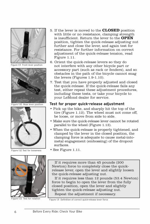
5. If the lever is moved to the CLOSED position with little or no resistance, clamping strength is insufficient. Return the lever to the OPEN position, tighten the quick-release adjusting nut further and close the lever, and again test for resistance. For further information on correct adjustment of the quick-release tension, read Figure 1.11.
6. Orient the quick-release levers so they do not interfere with any other bicycle part or accessory part (such as rack or fenders), and so obstacles in the path of the bicycle cannot snag the levers (Figures 1.9-1.10).
7. Test that you have properly adjusted and closed the quick-release. If the quick-release fails any test, either repeat these adjustment procedures, including these tests, or take your bicycle to your LeMond dealer for service.
Test for proper quick-release adjustment• Pick up the bike, and sharply hit the top of the
tire (Figure 1.12). The wheel must not come off, be loose, or move from side to side.
• Make sure the quick-release lever cannot be rotated parallel to the wheel (Figure 1.13).
• When the quick-release is properly tightened, and clamped by the lever in the closed position, the clamping force is adequate to cause metal-into-metal engagement (embossing) of the dropout surfaces.
• See Figure 1.11.
Figure 1.9 Front lever position
Figure 1.10 Rear lever position
If it requires more than 45 pounds (200 Newton) force to completely close the quick-release lever, open the lever and slightly loosen the quick-release adjusting nut.
If it requires less than 12 pounds (53.4 Newton) force to begin to open the lever from the fully closed position, open the lever and slightly tighten the quick-release adjusting nut.
Repeat the adjustment if necessary.
Figure 1.11 Definition of correct quick-release lever force
Before Every Ride: Check Your Bike
Figure 1.13 Test for rotation
Figure 1.12 Test for looseness

6 7CHAPTER ONE Guide to Safe On-and-Off Road Operation
Check your handlebars and stem for signs of stress or fatigue.
Carefully inspect your handlebars and stem for signs of fatigue: scratches, cracks, dents, deformation, or discolor-ation. If any part shows signs of damage or fatigue, replace the part before riding the bicycle. Also check that the handlebar plugs are properly inserted into both ends of the handlebars, and bar-ends.
8 9CHAPTER ONE Guide to Safe On-and-Off Road Operation
DURING EVERY RIDE: RIDE SAFELY
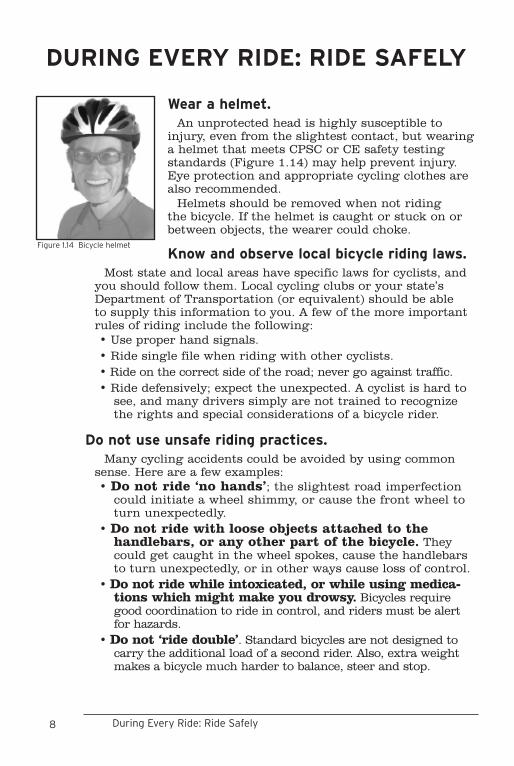
Wear a helmet. An unprotected head is highly susceptible to
injury, even from the slightest contact, but wearing a helmet that meets CPSC or CE safety testing standards (Figure 1.14) may help prevent injury. Eye protection and appropriate cycling clothes are also recommended.
Helmets should be removed when not riding the bicycle. If the helmet is caught or stuck on or between objects, the wearer could choke.
Know and observe local bicycle riding laws.Most state and local areas have specific laws for cyclists, and
you should follow them. Local cycling clubs or your state’s Department of Transportation (or equivalent) should be able to supply this information to you. A few of the more important rules of riding include the following:• Use proper hand signals.• Ride single file when riding with other cyclists.• Ride on the correct side of the road; never go against traffic.• Ride defensively; expect the unexpected. A cyclist is hard to
see, and many drivers simply are not trained to recognize the rights and special considerations of a bicycle rider.
Do not use unsafe riding practices.Many cycling accidents could be avoided by using common
sense. Here are a few examples:• Do not ride ‘no hands’; the slightest road imperfection
could initiate a wheel shimmy, or cause the front wheel to turn unexpectedly.
• Do not ride with loose objects attached to the handlebars, or any other part of the bicycle. They could get caught in the wheel spokes, cause the handlebars to turn unexpectedly, or in other ways cause loss of control.
• Do not ride while intoxicated, or while using medica-tions which might make you drowsy. Bicycles require good coordination to ride in control, and riders must be alert for hazards.
• Do not ‘ride double’. Standard bicycles are not designed to carry the additional load of a second rider. Also, extra weight makes a bicycle much harder to balance, steer and stop.
Figure 1.14 Bicycle helmet
During Every Ride: Ride Safely
8 9CHAPTER ONE Guide to Safe On-and-Off Road Operation
Ride defensively.To motorists, pedestrians, or other bicyclists,
you are not as visible as a car. Always watch for hazardous situations, and be ready to stop or take evasive action at all times.
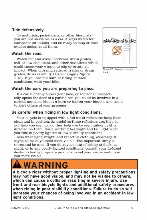
Watch the road.Watch for, and avoid, potholes, drain grates,
soft or low shoulders, and other deviations which could cause your wheels to slip or create an impact. When crossing railroad tracks or drain grates, do so carefully at a 90° angle (Figure 1.15). If you are not sure of riding surface conditions, walk your bike.
Watch the cars you are preparing to pass.If a car suddenly enters your lane, or someone unexpect-
edly opens the door of a parked car, you could be involved in a serious accident. Mount a horn or bell on your bicycle, and use it to alert others of your presence.
Be careful when riding in low light conditions. Your bicycle is equipped with a full set of reflectors; keep them
clean and in position. As useful as these reflectors are, they do not help you see, nor do they help you be seen unless light is directed on them. Use a working headlight and tail light when you ride in poorly lighted or low visibility conditions.
Also wear light, bright, and reflective clothing, especially at night, to make yourself more visible. The important thing is to see and be seen. If you do any amount of riding at dusk, at night, or in any poorly lighted conditions, consult your LeMond dealer to find appropriate products to aid your vision and make you more visible.
��
��
Figure 1.15 Angle for crossing tracks
WARNINGA bicycle rider without proper lighting and safety precautions may not have good vision, and may not be visible to others, which can cause a collision resulting in severe injury. Use front and rear bicycle lights and additional safety procedures when riding in poor visibility conditions. Failure to do so will increase your chances of being involved in an accident in low light conditions.
10 11CHAPTER ONE Guide to Safe On-and-Off Road Operation
Avoid introducing water to any bearings of your bicycle.The metal bearings in your bicycle allow the parts to rotate
smoothly. Water in contact with metal causes corrosion, which will make the bearings lose their smoothness. If any bearings on your bicycle get submerged in water, take your bicycle to your LeMond dealer for service.
Avoid high-pressure washing systems, like those at most car washes. The high pressure may force water into the bearings.
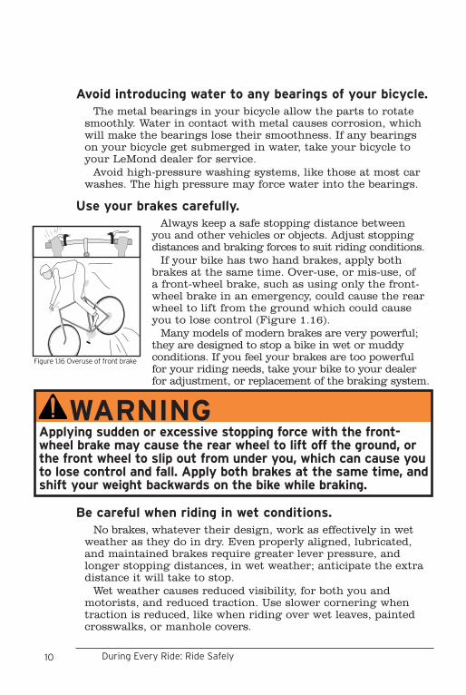
Use your brakes carefully.Always keep a safe stopping distance between
you and other vehicles or objects. Adjust stopping distances and braking forces to suit riding conditions.
If your bike has two hand brakes, apply both brakes at the same time. Over-use, or mis-use, of a front-wheel brake, such as using only the front-wheel brake in an emergency, could cause the rear wheel to lift from the ground which could cause you to lose control (Figure 1.16).
Many models of modern brakes are very powerful; they are designed to stop a bike in wet or muddy conditions. If you feel your brakes are too powerful for your riding needs, take your bike to your dealer for adjustment, or replacement of the braking system.
Be careful when riding in wet conditions.No brakes, whatever their design, work as effectively in wet
weather as they do in dry. Even properly aligned, lubricated, and maintained brakes require greater lever pressure, and longer stopping distances, in wet weather; anticipate the extra distance it will take to stop.
Wet weather causes reduced visibility, for both you and motorists, and reduced traction. Use slower cornering when traction is reduced, like when riding over wet leaves, painted crosswalks, or manhole covers.
WARNINGApplying sudden or excessive stopping force with the front-wheel brake may cause the rear wheel to lift off the ground, or the front wheel to slip out from under you, which can cause you to lose control and fall. Apply both brakes at the same time, and shift your weight backwards on the bike while braking.
During Every Ride: Ride Safely
Figure 1.16 Overuse of front brake
10 11CHAPTER ONE Guide to Safe On-and-Off Road Operation
Use special care when off-road riding.• Ride only on the trails. • Avoid rocks, branches, or depressions.• Never ride a road or touring bike on unpaved roads, trails, or
off-road.• Wear protective clothing including helmet, eye protection, and
gloves.• When approaching a descent, reduce your speed, keep your weight
back and low, and use the rear brake more than the front.
Avoid undue stress to your bicycle.Bicycles are not indestructible: as with anything mechanical,
every part of a bicycle has a limited useful life due to wear, stress, and fatigue. Fatigue refers to a low-stress force that, when repeated over a large number of cycles, can cause a material to fail or break. The length of the life of a part varies according to its design, materials, use, and maintenance. Although lighter frames or parts may, in some cases, have a longer life than heavier ones, it should be expected that light weight, high performance bicycles and parts require better care and more frequent inspections.
Regularly inspect your entire bicycle for signs of fatigue stress:• Dents• Cracks• Scratches• Deformation• Discoloration Fatigue can be accelerated by large forces from unsafe riding
practices:• Jumping your bicycle• Performing bicycle stunts• Severe off-road riding• Downhill riding• Any abnormal bike riding Carefully inspect your frame and components for signs of
fatigue before and after each ride. Even if you perform regular inspections, if you exceed the
limit of strength of your bicycle or a given part, it will fail.
12 13CHAPTER ONE Guide to Safe On-and-Off Road Operation
BEFORE, DURING, OR AFTER EVERY RIDE:TAKE CARE OF YOUR BIKE
Keep your bicycle clean.To work properly, your bicycle must be clean. If your frame
or a component is dirty, clean it with a soft, damp cloth and Wrench Force® bike cleaner or a similar product.
Avoid leaving your bicycle out in the weather.When not riding, store your bike where it will be protected
from rain, snow, sun, etc. Rain or snow may cause the metal on your bicycle to corrode. Ultraviolet radiation from the sun may fade the paint, or crack any rubber or plastic on the bicycle.
Use proper storage for your bicycle.Before storing your bike for an extended period of time,
clean and lubricate it, and polish the frame with Wrench Force® frame polish or a similar frame protectant. Hang the bicycle off the ground with the tires at approximately half pressure. Do not store the bike near electric motors, as ozone from motors destroys rubber and paint. Before riding the bicycle again, be certain it is in good working order.
Protect your bicycle from theft.Your new bicycle may be very attractive to thieves. Protect
yourself from theft:• Register the bicycle with your local police department.• Make sure you return your warranty card; we will
keep the serial number of your bike on file. Also, keep a record of the serial number in a safe place. See page ii for the location of the serial number on your bike.
• Purchase and use a lock. A good lock is effective against bolt cutters and saws. Follow the recommended locking procedures. Use your lock; never leave your bike unlocked while unattended, not even for a minute.
• With quick-release wheels, lock both of your wheels as well as your frame. If you have a quick-release seatpost binder, when locking your bike you may want to remove your seat and seatpost to prevent theft. However, avoid allowing water to enter your bicycle frame through the open seat tube of your bike.
Protect your bike from accidental damage.Park your bike in a place where it will be out of the way, and
make sure it cannot fall over. Do not lay the bike on its derail-leurs, as you may bend the rear derailleur or get dirt on the
Before, During, or After Every Ride: Take Care of Your Bike
12 13CHAPTER ONE Guide to Safe On-and-Off Road Operation
drivetrain. Don’t let the bike fall down, as this may cut the handlebar grips, or tear the seat. Incorrect use of bike racks may bend your wheels, as can riding over some obstacles.
These are just a few of the potential hazards you and your bike may encounter. If you suspect your bicycle has been damaged in any way, or tampered with, ensure there is no problem, or take it to your LeMond dealer for inspection and repair.
Use good shifting techniques.Some LeMond bicycles are equipped with a derailleur system,
where shifting is done by derailing, or moving the chain from one sprocket to another. Read the information for your type of bicycle in the following section:
• Shifting a bike with a derailleurThe left-hand shifter controls the front derailleur and the
right-hand shifter controls the rear derailleur. Use only one shifter at a time. Choose the gear combination most comfort-able for riding conditions, one that allows you to maintain a constant rate of pedaling. It is not essential that various gear combinations be used in sequence.
When shifting, plan ahead. Shift gears only when the pedals and chain are moving forward. Never attempt to shift gears when stopped or back-pedaling. When you shift, reduce the force on the pedals; excessive chain tension makes shifting difficult. This provides quicker, smoother shifting, will help avoid excessive chain and gear wear, and also will help avoid bent chains, derailleurs, and chainrings. Avoid shifting when going over bumpy surfaces, or railroad tracks; the chain may not shift properly, or may fall off.
With modern indexed shifting systems, a movement of the shifter from one position to the next (or movement of the shifter to the "shift" position) should promptly move the chain from one gear to the next. However, bikes equipped STI road shifters and triple chainrings may shift better, particularly when shifting from the smallest chainring to the middle, if you “hold” the lever for a moment before letting go of the shifter.
Prevent handlebar impact damage to your frame.With some bicycles, as the front wheel turns to extreme
angles, the handlebar may contact the frame. Prevent damage from handlebar impact by padding the handlebar parts, the frame, or both, at the points of contact. See your LeMond dealer for recommended protection devices or materials.
14 15CHAPTER ONE Guide to Safe On-and-Off Road Operation
Never modify your fork, frame, or components.Modifying the parts of your bike in any way, including the
frame, fork, and all the components, may make your bike unsafe. As an example, some bike frames have special surface treatments which add strength; these could be removed through poor paint stripping techniques. Removing the redundant wheel retention tabs on fork tips or peg-and-eyelet style redundant retention devices is another example of how modifying a bicycle could make it less functional.
Changing the forks on your bicycle could alter the steering of the bicycle, or add additional, unwanted stress:• Never add a suspension fork to a road bikeIf you must replace the fork on any bike, check with your
dealer or LeMond Bicycles' technical service department to ensure the new forks are compatible with the frame.
Any modification of your frame, fork, or components means that your bike no longer meets our specifications and will therefore void the bike’s warranty.
Take care of your frameset.LeMond bicycles use a variety of materials in the construc-
tion of framesets (frame and fork). Your frameset may require special attention in its care and maintenance. See pages 51-52 for information about your frameset.
Before, During, or After Every Ride: Take Care of Your Bike
WARNINGNever modify your frameset or parts in any way, including sanding, drilling, filing, removing redundant retention devices, installing incompatible forks, or by any other method. An improperly modified frame, fork, or component can cause you to lose control and fall.
14 15CHAPTER ONE Guide to Safe On-and-Off Road Operation
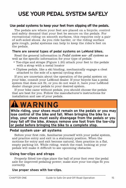
Use pedal systems to keep your feet from slipping off the pedals.The pedals are where your feet are placed on a bicycle; control
and safety demand that your feet be secure on the pedals. For recreational riding on smooth surfaces, this requires only a pair of soft-soled shoes. As you ride harder, or the riding surface gets rough, pedal systems can help to keep the rider's feet on the pedals.
There are several types of pedal systems on LeMond bikes.Read the general information in Pedal system use- all systems as
well as the specific information for your type of pedals:• Toe-clips and straps (Figure 1.20) attach your feet to the pedals
with a strap with a metal locator• Clipless pedals, like a ski binding, mechanically engage a cleat
attached to the sole of a special cycling shoe.If you are uncertain about the operation of the pedal system on
your bike, consult your LeMond dealer. If your bicycle has a pedal system that does not fit, or you do not want it, have your LeMond dealer change your pedals to your desired system.
If your bike came without pedals, you should choose the pedals that are best for you. Follow the manufacturer’s instructions for installation and use of your pedals.
Pedal system use- all systemsBefore your first ride, familiarize yourself with your pedal system,
and practice entry and exit in a stationary position. When the motions for entry and exit become natural, then practice in a flat, empty parking lot. While riding, watch the road; looking at your pedals will make it difficult to see upcoming obstacles.
Using toe-clips and strapsProperly fitted toe-clips place the ball of your foot over the pedal
axle for improved pedaling power; make sure your toe-clips fit you correctly.
Use proper shoes with toe-clips.
USE YOUR PEDAL SYSTEM SAFELY
WARNINGWhile riding, your shoes must remain on the pedals or you may lose control of the bike and fall. When bringing the bike to a stop, your shoes must easily disengage from the pedals or you may fall off the bike. Always remove one foot from the toe-clip or pedal before bringing the bike to a complete stop.

16 17CHAPTER ONE Guide to Safe On-and-Off Road Operation
Do not allow your feet to become entrapped in the toe-clips or straps. Use shoes which allow your foot to easily pass by the toe strap; do not use shoes with wide, heavily patterned soles. Always adjust the toe strap length with the buckle (Figure 1.17) to allow quick removal of your feet from the pedals.
To enter toe-clips1. Straddle the bike. 2. With your left foot on the ground, move the
right crank arm to its two o’clock position. 3. Place the toe of your shoe on the back edge of
the upside-down pedal, with your toes pointed slightly downward (Figure 1.18).
4. With a motion similar to scraping something off the bottom of your shoe, flip the pedal into an upright position and insert your foot into the toe-clip.
5. Push off with the left foot, and sit on the bicycle seat. Pedal one or two strokes to get moving and use the same technique to flip the other pedal and put your other foot into the second toe-clip.
To exit toe-clips1. Raise the heel so the sole of your shoe clears the
top of the pedal (Figure 1.19). 2. Withdraw your foot in an up-and-back motion,
and make sure your foot clears the pedal.3. As you bring the bike to a stop, place your
weighted foot on the ground.
Using clipless pedalsClipless pedals use a spring-loaded mechanism to
engage a cleat, a small plate attached to the bottom of a special cycling shoe. If you did not receive clipless pedal information for your bike, get a copy from your dealer, or contact us and we’ll send them to you. The following information is only meant to Figure 1.19 Lift foot to remove
from pedal
Figure 1.18 Ready to flip the pedal
Figure 1.17 Loosening the toe strap
supplement the pedal manufacturer’s instructions.
Use proper shoes and cleats with clipless pedals.Do not ride clipless pedals in 'street' shoes on clipped-in
platforms, or without engaging the cleats; the attachment of your feet to the pedals will be insecure. Always remove at least
Before, During, or After Every Ride: Use Your Pedal System Safely

16 17CHAPTER ONE Guide to Safe On-and-Off Road Operation
one shoe from the pedals before bringing the bicycle to a complete stop. Use only the cleats supplied by, or approved by, the pedal manufac-turer. Cleats from other pedal systems may not release properly.
Install and adjust cleats and pedals correctly.Incorrect installation of the cleats could cause
physical injury, so cleat installation should be done by your LeMond dealer. On most pedals, the force required for entry and exit is adjustable. Incorrect adjustment of the clipless pedal release force could prevent your foot from disengagement from the pedal. For adjustment information, read the pedal manufacturer’s instructions supplied with your pedals.
Keep your cleats and pedals in good conditionBefore attempting to engage your cleated shoe
into the pedal, always clean both the cleats and the pedals. Debris or contamination in the pedals, or on the cleats, may interfere with entry or exit of clipless pedals. If the cleat is worn, the cleat may not properly function with the clipless pedal.
To enter clipless pedals1. Engage the front of the cleat into the front of
the pedal (Figure 1.20) and press down with the ball of your foot. An audible click signifies completed entry into the pedal.
2. Check the attachment by attempting a rolling motion on the pedal (Figure 1.21). If you can roll your shoe off the pedal, start the procedure again.
3. To mount the bike, push down on this pedal while pushing off with the other foot, and at the same time, sit on the bicycle seat.
4. Once moving, put your other foot into the second pedal using the same technique.
To exit clipless pedals1. Twist your heel laterally away from the center-
line of the bike (Figure 1.22). 2. As you bring the bike to a stop, place your foot on the
ground.
Figure 1.20 Engaging the cleat
Figure 1.22 Release by twisting sideways
Figure 1.21 Test for cleat engagement
18 19CHAPTER TWO Periodic Maintenance
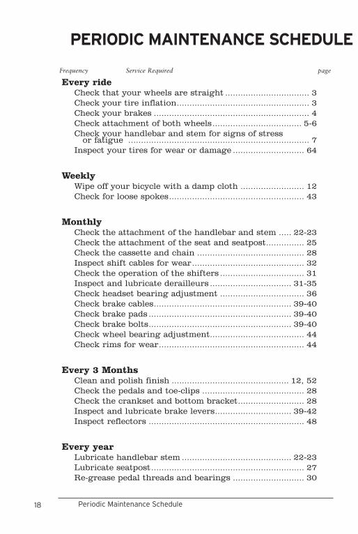
PERIODIC MAINTENANCE SCHEDULE
Frequency Service Required page
Every ride Check that your wheels are straight ................................. 3Check your tire inflation.................................................... 3Check your brakes ............................................................. 4Check attachment of both wheels................................... 5-6Check your handlebar and stem for signs of stress
or fatigue ....................................................................... 7Inspect your tires for wear or damage ............................ 64
Weekly Wipe off your bicycle with a damp cloth ......................... 12Check for loose spokes..................................................... 43
Monthly Check the attachment of the handlebar and stem ..... 22-23Check the attachment of the seat and seatpost............... 25Check the cassette and chain .......................................... 28Inspect shift cables for wear............................................ 32Check the operation of the shifters ................................. 31Inspect and lubricate derailleurs ................................ 31-35Check headset bearing adjustment ................................. 36Check brake cables...................................................... 39-40Check brake pads ........................................................ 39-40Check brake bolts........................................................ 39-40Check wheel bearing adjustment..................................... 44Check rims for wear......................................................... 44
Every 3 Months Clean and polish finish .............................................. 12, 52Check the pedals and toe-clips ........................................ 28Check the crankset and bottom bracket.......................... 28Inspect and lubricate brake levers.............................. 39-42Inspect reflectors ............................................................. 48
Every year Lubricate handlebar stem ........................................... 22-23Lubricate seatpost............................................................ 27Re-grease pedal threads and bearings ............................ 30
Periodic Maintenance Schedule
18 19CHAPTER TWO Periodic Maintenance
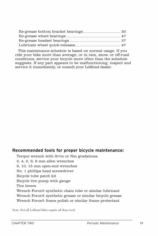
PERIODIC MAINTENANCE SCHEDULE
Re-grease bottom bracket bearings................................. 30Re-grease wheel bearings ................................................ 47Re-grease headset bearings ............................................. 37Lubricate wheel quick-releases........................................ 47
This maintenance schedule is based on normal usage. If you ride your bike more than average, or in rain, snow, or off-road conditions, service your bicycle more often than the schedule suggests. If any part appears to be malfunctioning, inspect and service it immediately, or consult your LeMond dealer.
Recommended tools for proper bicycle maintenance:Torque wrench with lb•in or Nm gradations2, 4, 5, 6, 8 mm allen wrenches9, 10, 15 mm open-end wrenchesNo. 1 phillips head screwdriverBicycle tube patch kitBicycle tire pump with gaugeTire leversWrench Force® synthetic chain lube or similar lubricantWrench Force® synthetic grease or similar bicycle greaseWrench Force® frame polish or similar frame protectant
Note: Not all LeMond bikes require all these tools

20 21CHAPTER THREE Inspection, Adjustment & LubricationPeriodic Maintenance Schedule
20 21CHAPTER THREE Inspection, Adjustment & Lubrication
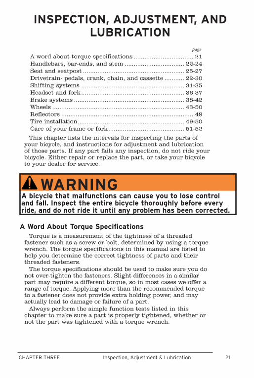
INSPECTION, ADJUSTMENT, AND LUBRICATION
A Word About Torque SpecificationsTorque is a measurement of the tightness of a threaded
fastener such as a screw or bolt, determined by using a torque wrench. The torque specifications in this manual are listed to help you determine the correct tightness of parts and their threaded fasteners.
The torque specifications should be used to make sure you do not over-tighten the fasteners. Slight differences in a similar part may require a different torque, so in most cases we offer a range of torque. Applying more than the recommended torque to a fastener does not provide extra holding power, and may actually lead to damage or failure of a part.
Always perform the simple function tests listed in this chapter to make sure a part is properly tightened, whether or not the part was tightened with a torque wrench.
WARNINGA bicycle that malfunctions can cause you to lose control and fall. Inspect the entire bicycle thoroughly before every ride, and do not ride it until any problem has been corrected.
A word about torque specifications ................................. 21Handlebars, bar-ends, and stem ................................. 22-24Seat and seatpost ........................................................ 25-27Drivetrain- pedals, crank, chain, and cassette ........... 22-30Shifting systems ......................................................... 31-35Headset and fork......................................................... 36-37Brake systems ............................................................. 38-42Wheels ......................................................................... 43-50Reflectors ......................................................................... 48Tire installation........................................................... 49-50Care of your frame or fork.......................................... 51-52
This chapter lists the intervals for inspecting the parts of your bicycle, and instructions for adjustment and lubrication of those parts. If any part fails any inspection, do not ride your bicycle. Either repair or replace the part, or take your bicycle to your dealer for service.
page
22 23CHAPTER THREE Inspection, Adjustment & Lubrication
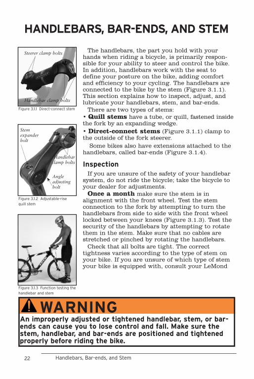
The handlebars, the part you hold with your hands when riding a bicycle, is primarily respon-sible for your ability to steer and control the bike. In addition, handlebars work with the seat to define your posture on the bike, adding comfort and efficiency to your cycling. The handlebars are connected to the bike by the stem (Figure 3.1.1). This section explains how to inspect, adjust, and lubricate your handlebars, stem, and bar-ends.
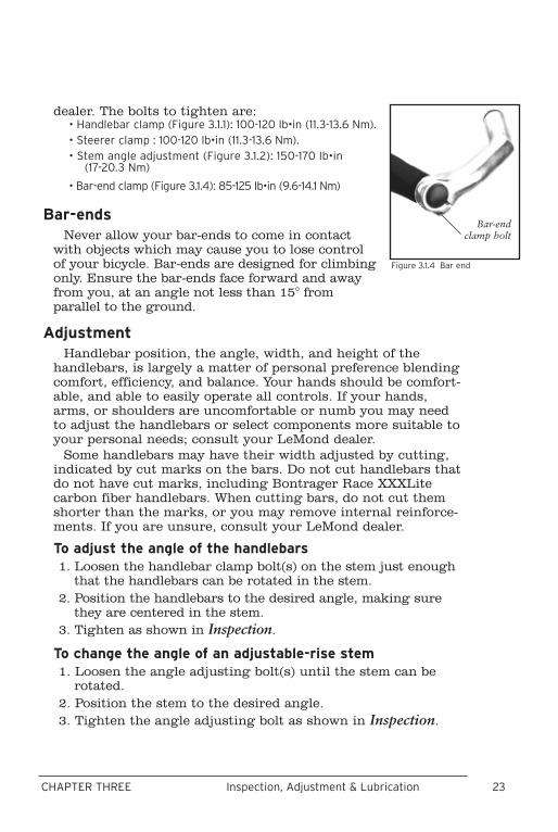
There are two types of stems:• Quill stems have a tube, or quill, fastened inside the fork by an expanding wedge.• Direct-connect stems (Figure 3.1.1) clamp to the outside of the fork steerer.
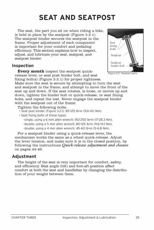
Some bikes also have extensions attached to the handlebars, called bar-ends (Figure 3.1.4).
InspectionIf you are unsure of the safety of your handlebar
system, do not ride the bicycle; take the bicycle to your dealer for adjustments.
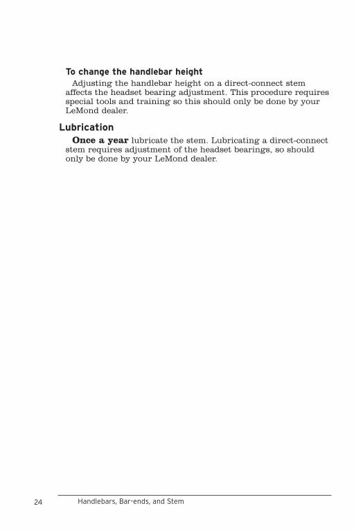
Once a month make sure the stem is in alignment with the front wheel. Test the stem connection to the fork by attempting to turn the handlebars from side to side with the front wheel locked between your knees (Figure 3.1.3). Test the security of the handlebars by attempting to rotate them in the stem. Make sure that no cables are stretched or pinched by rotating the handlebars.
Check that all bolts are tight. The correct tightness varies according to the type of stem on your bike. If you are unsure of which type of stem your bike is equipped with, consult your LeMond
Figure 3.1.3 Function testing the handlebar and stem
HANDLEBARS, BAR-ENDS, AND STEM
Steerer clamp bolts
Figure 3.1.1 Direct-connect stem
Handlebar clamp bolts
WARNINGAn improperly adjusted or tightened handlebar, stem, or bar-ends can cause you to lose control and fall. Make sure the stem, handlebar, and bar-ends are positioned and tightened properly before riding the bike.
Figure 3.1.2 Adjustable-rise quill stem
Angle adjusting bolt
Handlebar clamp bolts
Stem expander bolt
Handlebars, Bar-ends, and Stem
22 23CHAPTER THREE Inspection, Adjustment & Lubrication
dealer. The bolts to tighten are:• Handlebar clamp (Figure 3.1.1): 100-120 lb•in (11.3-13.6 Nm).• Steerer clamp : 100-120 lb•in (11.3-13.6 Nm). • Stem angle adjustment (Figure 3.1.2): 150-170 lb•in
(17-20.3 Nm)
• Bar-end clamp (Figure 3.1.4): 85-125 lb•in (9.6-14.1 Nm)
Bar-endsNever allow your bar-ends to come in contact
with objects which may cause you to lose control of your bicycle. Bar-ends are designed for climbing only. Ensure the bar-ends face forward and away from you, at an angle not less than 15° from parallel to the ground.
AdjustmentHandlebar position, the angle, width, and height of the
handlebars, is largely a matter of personal preference blending comfort, efficiency, and balance. Your hands should be comfort-able, and able to easily operate all controls. If your hands, arms, or shoulders are uncomfortable or numb you may need to adjust the handlebars or select components more suitable to your personal needs; consult your LeMond dealer.
Some handlebars may have their width adjusted by cutting, indicated by cut marks on the bars. Do not cut handlebars that do not have cut marks, including Bontrager Race XXXLite carbon fiber handlebars. When cutting bars, do not cut them shorter than the marks, or you may remove internal reinforce-ments. If you are unsure, consult your LeMond dealer.
To adjust the angle of the handlebars1. Loosen the handlebar clamp bolt(s) on the stem just enough
that the handlebars can be rotated in the stem. 2. Position the handlebars to the desired angle, making sure
they are centered in the stem. 3. Tighten as shown in Inspection.
To change the angle of an adjustable-rise stem1. Loosen the angle adjusting bolt(s) until the stem can be
rotated.2. Position the stem to the desired angle.3. Tighten the angle adjusting bolt as shown in Inspection.
Figure 3.1.4 Bar end
Bar-end clamp bolt
24 25CHAPTER THREE Inspection, Adjustment & Lubrication
To change the handlebar height Adjusting the handlebar height on a direct-connect stem
affects the headset bearing adjustment. This procedure requires special tools and training so this should only be done by your LeMond dealer.
LubricationOnce a year lubricate the stem. Lubricating a direct-connect
stem requires adjustment of the headset bearings, so should only be done by your LeMond dealer.
Handlebars, Bar-ends, and Stem
24 25CHAPTER THREE Inspection, Adjustment & Lubrication
The seat, the part you sit on when riding a bike, is held in place by the seatpost (Figure 3.2.1). The seatpost binder secures the seatpost in the frame. Proper adjustment of each component is important for your comfort and pedaling efficiency. This section explains how to inspect, adjust, and lubricate your seat, seatpost, and seatpost binder.
InspectionEvery month inspect the seatpost quick-
release lever, or seat post binder bolt, and seat fixing bolt(s) (Figure 3.2.1) for proper tightness. Make sure the seat is secure by attempting to turn the seat and seatpost in the frame, and attempt to move the front of the seat up and down. If the seat rotates, is loose, or moves up and down, tighten the binder bolt or quick-release, or seat fixing bolts, and repeat the test. Never engage the seatpost binder with the seatpost out of the frame.
Tighten the following bolts:• Seat post binder (Figure 3.2.1): 85-125 lb•in (9.6-14.1 Nm).• Seat fixing bolts of these types: -single, using a 6 mm allen wrench: 150-250 lb•in (17-28.3 Nm). -double, using a 5 mm allen wrench: 80-125 lb•in (9.6-14.1 Nm). -double, using a 4 mm allen wrench: 45-60 lb•in (5-6.8 Nm).
For a seatpost binder using a quick-release lever, the mechanism works the same as a wheel quick-release. Adjust the lever tension, and make sure it is in the closed position, by following the instructions Quick-release adjustment and closure on pages 44-46.
AdjustmentThe height of the seat is very important for comfort, safety,
and efficiency. Seat angle (tilt) and fore-aft position affect comfort at both the seat and handlebar by changing the distribu-tion of your weight between them.
SEAT AND SEATPOST
Figure 3.2.1 Seatpost parts
Seat fixing bolts
Seatpost
Seatpost binder bolt
26 27CHAPTER THREE Inspection, Adjustment & Lubrication
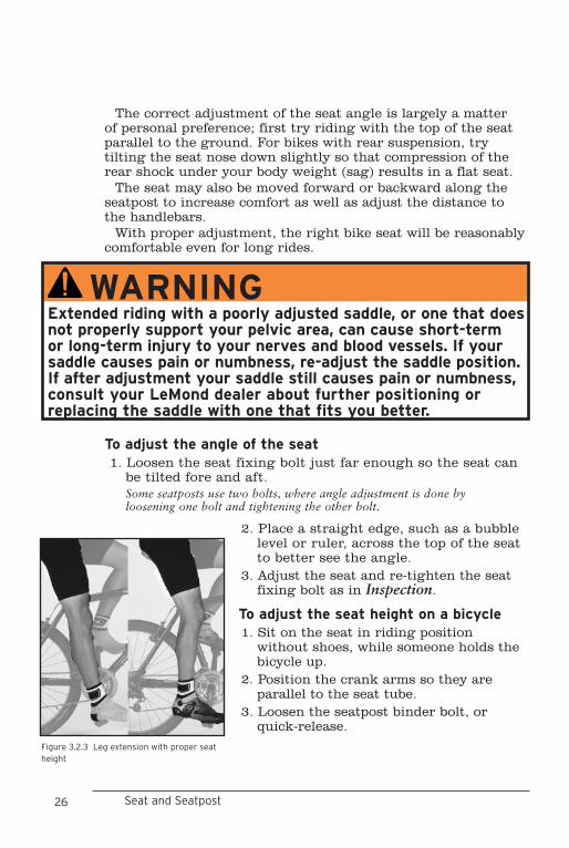
The correct adjustment of the seat angle is largely a matter of personal preference; first try riding with the top of the seat parallel to the ground. For bikes with rear suspension, try tilting the seat nose down slightly so that compression of the rear shock under your body weight (sag) results in a flat seat.
The seat may also be moved forward or backward along the seatpost to increase comfort as well as adjust the distance to the handlebars.
With proper adjustment, the right bike seat will be reasonably comfortable even for long rides.
To adjust the angle of the seat1. Loosen the seat fixing bolt just far enough so the seat can
be tilted fore and aft. Some seatposts use two bolts, where angle adjustment is done by loosening one bolt and tightening the other bolt.
Seat and Seatpost
WARNINGExtended riding with a poorly adjusted saddle, or one that does not properly support your pelvic area, can cause short-term or long-term injury to your nerves and blood vessels. If your saddle causes pain or numbness, re-adjust the saddle position. If after adjustment your saddle still causes pain or numbness, consult your LeMond dealer about further positioning or replacing the saddle with one that fits you better.
Figure 3.2.3 Leg extension with proper seat height
2. Place a straight edge, such as a bubble level or ruler, across the top of the seat to better see the angle.
3. Adjust the seat and re-tighten the seat fixing bolt as in Inspection.
To adjust the seat height on a bicycle1. Sit on the seat in riding position
without shoes, while someone holds the bicycle up.
2. Position the crank arms so they are parallel to the seat tube.
3. Loosen the seatpost binder bolt, or quick-release.
26 27CHAPTER THREE Inspection, Adjustment & Lubrication
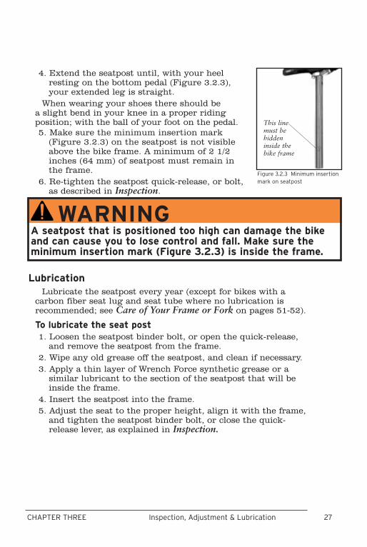
4. Extend the seatpost until, with your heel resting on the bottom pedal (Figure 3.2.3), your extended leg is straight.
When wearing your shoes there should be a slight bend in your knee in a proper riding position; with the ball of your foot on the pedal. 5. Make sure the minimum insertion mark
(Figure 3.2.3) on the seatpost is not visible above the bike frame. A minimum of 2 1/2 inches (64 mm) of seatpost must remain in the frame.
6. Re-tighten the seatpost quick-release, or bolt, as described in Inspection.
LubricationLubricate the seatpost every year (except for bikes with a
carbon fiber seat lug and seat tube where no lubrication is recommended; see Care of Your Frame or Fork on pages 51-52).
To lubricate the seat post1. Loosen the seatpost binder bolt, or open the quick-release,
and remove the seatpost from the frame. 2. Wipe any old grease off the seatpost, and clean if necessary. 3. Apply a thin layer of Wrench Force synthetic grease or a
similar lubricant to the section of the seatpost that will be inside the frame.
4. Insert the seatpost into the frame.5. Adjust the seat to the proper height, align it with the frame,
and tighten the seatpost binder bolt, or close the quick-release lever, as explained in Inspection.
Figure 3.2.3 Minimum insertion mark on seatpost
This line must be hidden inside the bike frame
WARNINGA seatpost that is positioned too high can damage the bike and can cause you to lose control and fall. Make sure the minimum insertion mark (Figure 3.2.3) is inside the frame.
28 29CHAPTER THREE Inspection, Adjustment & Lubrication
DRIVETRAIN:
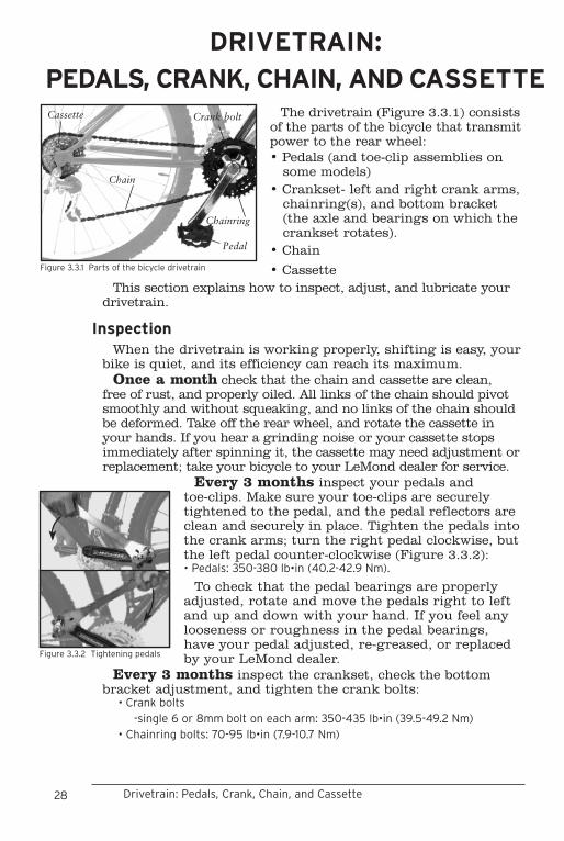
PEDALS, CRANK, CHAIN, AND CASSETTEThe drivetrain (Figure 3.3.1) consists
of the parts of the bicycle that transmit power to the rear wheel: • Pedals (and toe-clip assemblies on
some models)• Crankset- left and right crank arms,
chainring(s), and bottom bracket (the axle and bearings on which the crankset rotates).
• Chain
Cassette
Chain
Pedal
Chainring
Crank bolt
Figure 3.3.1 Parts of the bicycle drivetrain
Drivetrain: Pedals, Crank, Chain, and Cassette
• Cassette This section explains how to inspect, adjust, and lubricate your
drivetrain.
InspectionWhen the drivetrain is working properly, shifting is easy, your
bike is quiet, and its efficiency can reach its maximum. Once a month check that the chain and cassette are clean,
free of rust, and properly oiled. All links of the chain should pivot smoothly and without squeaking, and no links of the chain should be deformed. Take off the rear wheel, and rotate the cassette in your hands. If you hear a grinding noise or your cassette stops immediately after spinning it, the cassette may need adjustment or replacement; take your bicycle to your LeMond dealer for service.
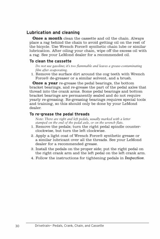
Every 3 months inspect your pedals and toe-clips. Make sure your toe-clips are securely tightened to the pedal, and the pedal reflectors are clean and securely in place. Tighten the pedals into the crank arms; turn the right pedal clockwise, but the left pedal counter-clockwise (Figure 3.3.2): • Pedals: 350-380 lb•in (40.2-42.9 Nm).
To check that the pedal bearings are properly adjusted, rotate and move the pedals right to left and up and down with your hand. If you feel any looseness or roughness in the pedal bearings, have your pedal adjusted, re-greased, or replaced by your LeMond dealer.
Every 3 months inspect the crankset, check the bottom bracket adjustment, and tighten the crank bolts:
• Crank bolts -single 6 or 8mm bolt on each arm: 350-435 lb•in (39.5-49.2 Nm)• Chainring bolts: 70-95 lb•in (7.9-10.7 Nm)
Figure 3.3.2 Tightening pedals

28 29CHAPTER THREE Inspection, Adjustment & Lubrication
To check the bottom bracket bearing adjustment 1. Lift the chain from the chainrings.2. Rotate the crank so that one of the arms is parallel the seat tube.3. Put one hand on the crank arm and one hand on the seat
tube, and attempt to move the crank arm laterally toward and away from the seat tube.
4. Spin the cranks. If the crank feels or sounds loose, or if the motion stops
abruptly or you hear a grinding noise coming from the bearings, the bearings need to be adjusted or re-greased by your LeMond dealer.
Clean the chainrings and inspect them for damage. If any teeth are bent or broken, have the chainring replaced by your LeMond dealer. Note that on some chainrings, a few teeth have a special shape to enhance shifting.
Every 3 months check your chain for wear with a chain wear gauge or a ruler. Each full link of a new chain measures one inch. If 12 links of your chain measures 121/8 inches or more, it should be replaced. With good maintenance, a chain usually lasts 1000 to 1500 miles on a road bike, less on a mountain bike. Replacing the chain takes special tools and training and should only be done by your LeMond dealer.
AdjustmentTo adjust the release force of clipless pedal, or to adjust the
cleats, read Use Your Pedal System Safely in Chapter One.Adjustment of any bearings in the drivetrain including the
bottom bracket, cassette, or pedals, requires special tools and training. These services should only be performed by your LeMond dealer.
30 31CHAPTER THREE Inspection, Adjustment & Lubrication
Lubrication and cleaningOnce a month clean the cassette and oil the chain. Always
place a rag behind the chain to avoid getting oil on the rest of the bicycle. Use Wrench Force® synthetic chain lube or similar lubrication. After oiling your chain, wipe off the excess oil with a rag. See your LeMond dealer for a recommended oil.
To clean the cassetteDo not use gasoline; it’s too flammable and leaves a grease-contaminating film after evaporating.
1. Remove the surface dirt around the cog teeth with Wrench Force® de-greaser or a similar solvent, and a brush.
Once a year re-grease the pedal bearings, the bottom bracket bearings, and re-grease the part of the pedal axles that thread into the crank arms. Some pedal bearings and bottom bracket bearings are permanently sealed and do not require yearly re-greasing. Re-greasing bearings requires special tools and training, so this should only be done by your LeMond dealer.
To re-grease the pedal threadsNote: There are right and left pedals, usually marked with a letter stamped on the end of the pedal axle, or on the wrench flats.
1. Remove the pedals; turn the right pedal spindle counter-clockwise, but turn the left clockwise.
2. Apply a light coat of Wrench Force® synthetic grease or a similar lubricant over all the threads. See your LeMond dealer for a recommended grease.
3. Install the pedals on the proper side; put the right pedal on the right crank arm and the left pedal on the left crank arm.
4. Follow the instructions for tightening pedals in Inspection.
Drivetrain— Pedals, Crank, Chain, and Cassette
30 31CHAPTER THREE Inspection, Adjustment & Lubrication
DERAILLEUR SHIFT SYSTEMS
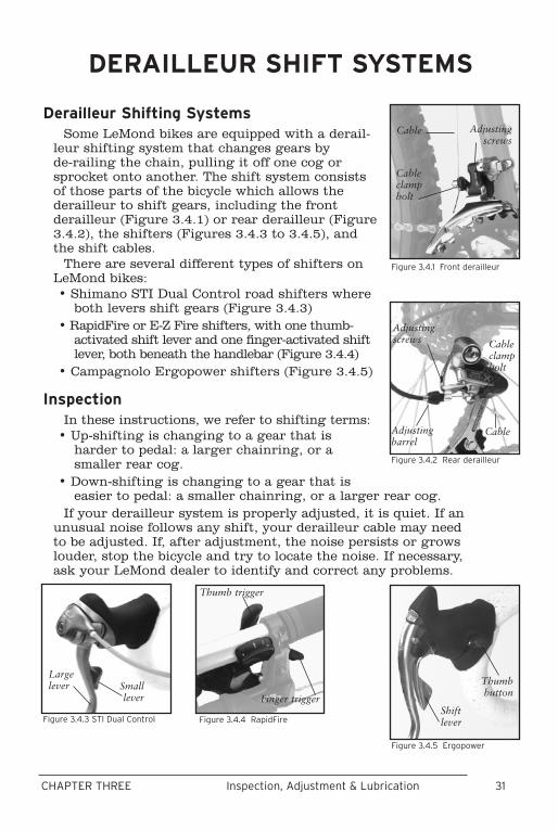
Derailleur Shifting SystemsSome LeMond bikes are equipped with a derail-
leur shifting system that changes gears by de-railing the chain, pulling it off one cog or sprocket onto another. The shift system consists of those parts of the bicycle which allows the derailleur to shift gears, including the front derailleur (Figure 3.4.1) or rear derailleur (Figure 3.4.2), the shifters (Figures 3.4.3 to 3.4.5), and the shift cables.
There are several different types of shifters on LeMond bikes:• Shimano STI Dual Control road shifters where
both levers shift gears (Figure 3.4.3) • RapidFire or E-Z Fire shifters, with one thumb-
activated shift lever and one finger-activated shift lever, both beneath the handlebar (Figure 3.4.4)
• Campagnolo Ergopower shifters (Figure 3.4.5)
InspectionIn these instructions, we refer to shifting terms:
• Up-shifting is changing to a gear that is harder to pedal: a larger chainring, or a smaller rear cog.
• Down-shifting is changing to a gear that is easier to pedal: a smaller chainring, or a larger rear cog.
If your derailleur system is properly adjusted, it is quiet. If an unusual noise follows any shift, your derailleur cable may need to be adjusted. If, after adjustment, the noise persists or grows louder, stop the bicycle and try to locate the noise. If necessary, ask your LeMond dealer to identify and correct any problems.
Figure 3.4.1 Front derailleur
Cable
Cable clamp bolt
Adjusting screws
Figure 3.4.2 Rear derailleur
Cable
Cable clamp bolt
Adjusting screws
Adjusting barrel
Figure 3.4.3 STI Dual Control
Large lever Small
lever
Figure 3.4.5 Ergopower
Shift lever
Thumb button
Figure 3.4.4 RapidFire
Thumb trigger
Finger trigger
32 33CHAPTER THREE Inspection, Adjustment & Lubrication
Once a month check the shift cables for kinks, rust, broken strands, or frayed ends. Also check the housing for loose wire strands, bent ends, cuts, and wear. If you suspect a problem with your shift cables, do not ride your bicycle; follow the instructions To replace a shift cable, or have your LeMond dealer service your bicycle.
Once a month check the operation of the left shift levers/front derailleur. When down-shifted, the front derailleur should shift the chain from a larger chainring to a smaller one. When up-shifted, the derailleur should shift the chain from a smaller chainring to a larger one. After the shift, by moving the shifter slightly, you should be able to position the front derailleur such that it does not rub on the chain. The chain should not fall off the inner-most or outer-most chainrings at any time.
Once a month check the operation of the right shift levers/rear derailleur. When down-shifted, the rear derailleur should shift the chain from a smaller cog to a larger one. When up-shifted, the rear derailleur should shift the chain from a larger cog to a smaller one. After the shift, the rear derailleur should be positioned such that the chain runs smoothly without jumping. The chain should not fall off the inner-most or outer-most cogs at any time.
AdjustmentDerailleur adjustment should be done with the bike held firmly
in a workstand, or with someone holding the rear wheel off the ground, such that the drivetrain and shift system can be operated while the bike remains stationary.
To adjust the low gear position of the front derailleur1. Shift the chain onto the smallest front chainring and the
largest cassette cog. 2. Loosen the front derailleur cable clamp bolt (Figure 3.4.1)
until the cable is free. 3. Turn the low gear adjusting screw (marked “L”, Figure
3.4.6) until the inner chain guide of the derailleur is approximately 0.5 mm from the chain.
4. Pull on the cable end, and down-shift the left shift lever several times so it is in the small-chainring position.
5. Turn the shift cable adjusting barrel to its most clockwise position.
6. Insert the cable in the groove found next to the derailleur cable clamp bolt, pull the cable taut, and clamp the cable:
• Front derailleur cable clamp bolt: 44-60 lb•in (5.0-6.8 Nm).
Derailleur Shift Systems
32 33CHAPTER THREE Inspection, Adjustment & Lubrication
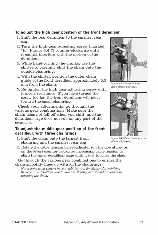
To adjust the high gear position of the front derailleur1. Shift the rear derailleur to the smallest rear
cog. 2. Turn the high-gear adjusting screw (marked
“H”, Figure 3.4.7) counter-clockwise until it cannot interfere with the motion of the derailleur.
3. While hand-turning the cranks, use the shifter to carefully shift the chain onto the outside chainring.
4. With the shifter, position the outer chain guide of the front derailleur approximately 0.5 mm from the chain.
5. Re-tighten the high gear adjusting screw until it meets resistance. If you have turned the screw too far, the front derailleur will move toward the small chainring.
Check your adjustments; go through the various gear combinations. Make sure the chain does not fall off when you shift, and the derailleur cage does not rub on any part of the crankset.
To adjust the middle gear position of the front derailleur, with three chainrings1. Shift the chain onto the largest front
chainring and the smallest rear cog. 2. Rotate the cable tension barrel-adjuster (on the downtube, or
on the lever) counter-clockwise increasing cable tension to align the inner derailleur cage until it just touches the chain.
Go through the various gear combinations to ensure the chain smoothly lines up with all the chainrings.
Note: some front shifters have a ‘tab’ feature. By slightly downshifting the lever, the derailleur should move in slightly, and should no longer be touching the chain.
Figure 3.4.6 Inner limiting screw effects (low gear)
Figure 3.4.7 Outer limiting screw effects (high gear)

34 35CHAPTER THREE Inspection, Adjustment & LubricationDerailleur Shift Systems
To adjust the high gear position of the rear derailleur1. Shift the chain onto the smallest rear cog and
the largest front chainring.2. Loosen the cable clamp bolt (Figure 3.4.2) until
the cable is free. 3. Stand behind the bicycle to see that the smallest
rear cog, the chain, and the two derailleur pulleys are in line.
4. If they are not aligned, turn the high gear adjusting screw (usually marked “H”, Figure 3.4.8) until this line is established.
5. While pulling on the cable, up-shift until the shifter is in the small cog position.
6. Turn the adjusting barrel on the shifter, or down tube, all the way clockwise. Turn the adjusting barrel on the rear derailleur all the way clockwise, and then one turn counter-clockwise.
7. Insert the cable into the clamp bolt groove on the rear derailleur, pull the shift cable taut, and clamp the cable:
• Rear derailleur cable clamp bolt: 44-60 lb•in (5.0-6.8 Nm).
To adjust the low gear position of the rear derailleur1. Turn the low gear adjusting screw on the rear
derailleur (usually marked “L”, Figure 3.4.9) far enough counter-clockwise so that it will not restrict the movement of the derailleur.
2. Carefully shift the chain onto the smallest front chainring and the largest rear cog. Do not over-shift the rear derail-leur, or the chain may wedge between the large cog and the spokes.
3. Position the rear derailleur pulleys in line with the largest cog.4. Turn the low gear adjusting screw clockwise until it meets
resistance. If you have turned it too far, the derailleur will move toward the outside of the bicycle.
5. Go through the various gear combinations. Make sure the chain does not fall off when you shift.
To align the indexing system of the rear derailleur1. Shift the chain onto the largest front chainring and the
smallest rear cog.
Figure 3.4.9 Inner limiting screw effects (low gear)
Figure 3.4.8 Outer limiting screw effects (high gear)

34 35CHAPTER THREE Inspection, Adjustment & Lubrication
2. Shift the rear shifter one click. 3. Check if the chain moves smoothly to the next gear.4. If the chain makes excessive noise or does not shift, turn the
barrel-adjuster counter-clockwise in small increments and check again for a smooth shift.
If instead, the chain moves to the third smallest cog, turn the barrel adjuster clockwise until alignment with the derailleur pulleys and the second smallest cog is achieved. Go through the various gear combinations to ensure the chain smoothly lines up with all the rear cogs.
If the derailleur cannot be adjusted in this manner, the derailleur hanger may be out of alignment; take the bike to your LeMond dealer for service.
To replace a shift cable1. Shift the chain onto the smallest front chainring and the
smallest rear cog. 2. Note the path the derailleur cable follows, loosen the derail-
leur cable clamp bolt holding the bad cable, and remove the cable through the shift lever.Some shifters have a covered cable access: either a screw, or a cover held by a screw. If you can't find the cable access for your shifter, check with your dealer.
3. Inspect the housings; if they are damaged or rusty, replace them. Note: If you replace any housings, make sure the pieces are of the correct type of housing, and cut them to the proper length (use the old pieces as guides). Make sure the housing ends are free of burrs; the cable should pass freely through these ends.
4. Grease the new cable and feed it through the lever and all of the cable guides and housings, and the cable clamp bolt following the same path as the old cable.
5. Follow the directions for derailleur adjustment.6. Cut the cable so no more than 2 inches (51 mm) of cable
length extends beyond the cable clamp bolt. 7. Crimp on a metal end-cap to prevent fraying of the cable
end, or apply some solder to the end of the cable.
LubricationEvery month, lubricate all pivot points on both the front
and rear derailleurs, including the derailleur pulleys on the rear derailleur, with Wrench Force® synthetic chain lube or similar lubrication.
Whenever a cable is replaced, lubricate the cable, where it passes through the housing, with a light grease.
36 37CHAPTER THREE Inspection, Adjustment & Lubrication
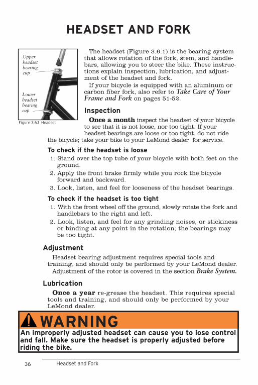
The headset (Figure 3.6.1) is the bearing system that allows rotation of the fork, stem, and handle-bars, allowing you to steer the bike. These instruc-tions explain inspection, lubrication, and adjust-ment of the headset and fork.
If your bicycle is equipped with an aluminum or carbon fiber fork, also refer to Take Care of Your Frame and Fork on pages 51-52.
InspectionOnce a month inspect the headset of your bicycle
to see that it is not loose, nor too tight. If your headset bearings are loose or too tight, do not ride
the bicycle; take your bike to your LeMond dealer for service.
To check if the headset is loose1. Stand over the top tube of your bicycle with both feet on the
ground. 2. Apply the front brake firmly while you rock the bicycle
forward and backward. 3. Look, listen, and feel for looseness of the headset bearings.
To check if the headset is too tight1. With the front wheel off the ground, slowly rotate the fork and
handlebars to the right and left. 2. Look, listen, and feel for any grinding noises, or stickiness
or binding at any point in the rotation; the bearings may be too tight.
AdjustmentHeadset bearing adjustment requires special tools and
training, and should only be performed by your LeMond dealer. Adjustment of the rotor is covered in the section Brake System.
LubricationOnce a year re-grease the headset. This requires special
tools and training, and should only be performed by your LeMond dealer.
WARNINGAn improperly adjusted headset can cause you to lose control and fall. Make sure the headset is properly adjusted before riding the bike.
HEADSET AND FORK
Headset and Fork
Figure 3.6.1 Headset
Upper headset bearing cup
Lower headset bearing cup

36 37CHAPTER THREE Inspection, Adjustment & Lubrication
38 39CHAPTER THREE Inspection, Adjustment & Lubrication
The brake system allows you to slow or stop your bike, a function critical to your safety.
These instructions explain how to inspect, adjust, and lubricate a bicycle brake. Read the general information in Braking system pointers- all systems as well as the specific information for the type of brakes on your bike.
Brake system pointers- all systemsDifferent brake designs have varying amounts of stopping
power. If you are dis-satisfied, or uncomfortable, with the stopping power of your bicycle brakes, consult your LeMond dealer.
With any braking system, failure to properly adjust, maintain, and use your brakes may result in a loss of control and injury. If you are unsure of the brake adjustment, or suspect any problem, do not ride your bicycle; have your LeMond dealer service your bicycle.
The brake system is difficult to adjust properly without the proper tools and training. It is strongly recommended that adjustment of a brake be done by your LeMond dealer. If you need more specific information regarding your brake system, contact your LeMond dealer.
Some types of brakes are not compatible with some types of brake levers. With any brake, use only levers recognized as compatible, like those supplied with your bike. As an example, direct-pull brakes (Figure 3.7.2) have increased leverage and stopping power, requiring special brake levers to manage the power.
If your bike is equipped with brake levers offering adjustable braking force, read and follow the manufacturers instructions supplied with your bike before making any adjustment to the braking force.
BRAKE SYSTEMS
Brake Systems
WARNINGNever ride a bike if you are not certain the brakes are working properly, or you if suspect a problem with the brake cables. Malfunctioning brakes can cause you to lose control and fall. If your brakes are not working properly, re-adjust them or take the bike to your LeMond dealer for service.

38 39CHAPTER THREE Inspection, Adjustment & Lubrication
IntroductionThis system consists of one of several types of
hand-operated brake levers and brakes, including road caliper brakes (Figure 3.7.1), direct-pull brakes (Figure 3.7.2), and cantilever brakes (Figure 3.7.4). With this system, the lever is connected to the brake by a cable. By squeezing the lever, pressure is applied to the wheel rim by brake pads. This slows the rotation of the wheel, which slows the bike.
This system consists of several parts:• Rim• Brake lever• Brake cable and housing• Brake caliperNever use rims designed specifically for disc
brakes. Rim brakes require a flat sidewall on the rim for proper braking action.
Inspection When the brakes are not applied, the brake
pads should be 1-2mm from the rim. Brake pads should be aligned with the rim surface (Figure 3.7.3). If your brakes are too tight, too loose, or not centered on the rim, adjust them before riding the bike.
Figure 3.7.3 shows toe-in, an angular alignment of the brake pad, which can be adjusted to prevent squealing of the brakes. Used brake pads, or some new direct-pull type brakes, may not require toe-in.
Every month check the brake cables on your bike for kinks, rust, broken strands, and frayed ends, and check the housing for bent ends, cuts, stretched coils, and wear. Replace any part which does not pass inspection.
Pad and rim should be parallelBrake pad
aligned with the rim surface
Direction of rim rotation
Figure 3.7.3 Brake pad alignment
0.5 - 1 mm toe in
Figure 3.7.1 Road caliper brake
Barrel adjuster
Centering screw
Pad fixing
bolt
No contact
Figure 3.7.2 Direct-pull brake
Arm fixing
bolt
Cable clamp bolt
Centering screw
Pad fix-ing bolt
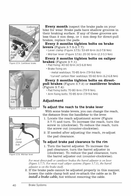
40 41CHAPTER THREE Inspection, Adjustment & Lubrication
Every month inspect the brake pads on your bike for wear. Brake pads have shallow grooves in their braking surface. If any of these grooves are less than 2 mm deep, or 1 mm deep for direct-pull brakes, replace the pads.
Every 3 months tighten bolts on brake levers (Figure 3.7.5-3.7.7):
• Lever clamp (Figure 3.7.5): 53-69 lb•in (6.0-7.8 Nm)
• Mid-bar lever (Figure 3.7.6): 20-30 lb•in (2.3-3.3 Nm)
Every 3 months tighten bolts on caliper brakes (Figure 3.7.1):
• Pad fixing: 40-60 lb•in (4.5-6.8 Nm) • Brake fixing on: - metal seatstays: 70-85 lb•in (7.9-9.6 Nm) -'curved' carbon fiber seatstays: 55-60 lb•in (6.2-6.8 Nm)
Every 3 months tighten bolts on direct-pull brakes (Figure 3.7.2) or cantilever brakes (Figure 3.7.4):
• Pad fixing bolts: 70-80 lb•in (7.9-9 Nm). • Arm fixing bolts: 70-85 lb•in (7.9-9.6 Nm)
Adjustment
To adjust the reach to the brake leverWith some brake levers, you can change the reach,
the distance from the handlebar to the lever.1. Locate the reach adjustment screw (Figure
3.7.7) and turn. To increase the reach, turn the screw in (clockwise). To reduce the reach, turn the screw out (counter-clockwise).
2. If needed after adjusting the reach, re-adjust the pad clearance.
To adjust brake pad clearance to the rim1. Turn the barrel adjuster. To increase the
pad clearance, turn the barrel adjuster in (clockwise). To reduce the pad clearance, turn the barrel adjuster out (counter-clockwise).
Brake Systems
Figure 3.7.5 Lever clamp bolt
Lever clamp bolt
Figure 3.7.4 Cantilever brake
Linkwire
Pad fixing
bolt
Arm fixing bolt
Centering screw
Figure 3.7.6 Mid-bar lever
Lever clamp bolt
For most direct-pull or cantilever brakes the barrel adjuster is on lever (Figure 3.7.7). For most road caliper systems (Figure 3.7.1), the barrel adjuster is on the brake itself.
2. If the brake pads cannot be adjusted properly in this manner, loosen the cable clamp bolt and re-attach the cable as in To install a brake cable, but without removing the cable.
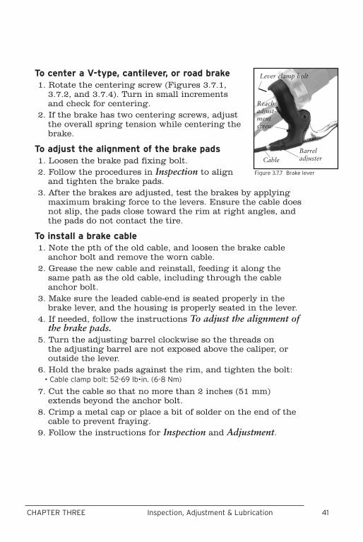
40 41CHAPTER THREE Inspection, Adjustment & Lubrication
To center a V-type, cantilever, or road brake1. Rotate the centering screw (Figures 3.7.1,
3.7.2, and 3.7.4). Turn in small increments and check for centering.
2. If the brake has two centering screws, adjust the overall spring tension while centering the brake.
To adjust the alignment of the brake pads1. Loosen the brake pad fixing bolt.2. Follow the procedures in Inspection to align
and tighten the brake pads. 3. After the brakes are adjusted, test the brakes by applying
maximum braking force to the levers. Ensure the cable does not slip, the pads close toward the rim at right angles, and the pads do not contact the tire.
To install a brake cable1. Note the pth of the old cable, and loosen the brake cable
anchor bolt and remove the worn cable. 2. Grease the new cable and reinstall, feeding it along the
same path as the old cable, including through the cable anchor bolt.
3. Make sure the leaded cable-end is seated properly in the brake lever, and the housing is properly seated in the lever.
4. If needed, follow the instructions To adjust the alignment of the brake pads.
5. Turn the adjusting barrel clockwise so the threads on the adjusting barrel are not exposed above the caliper, or outside the lever.
6. Hold the brake pads against the rim, and tighten the bolt:• Cable clamp bolt: 52-69 lb•in. (6-8 Nm)
7. Cut the cable so that no more than 2 inches (51 mm) extends beyond the anchor bolt.
8. Crimp a metal cap or place a bit of solder on the end of the cable to prevent fraying.
9. Follow the instructions for Inspection and Adjustment.
Reach adjust-ment screw
Barrel adjusterCable
Lever clamp bolt
Figure 3.7.7 Brake lever
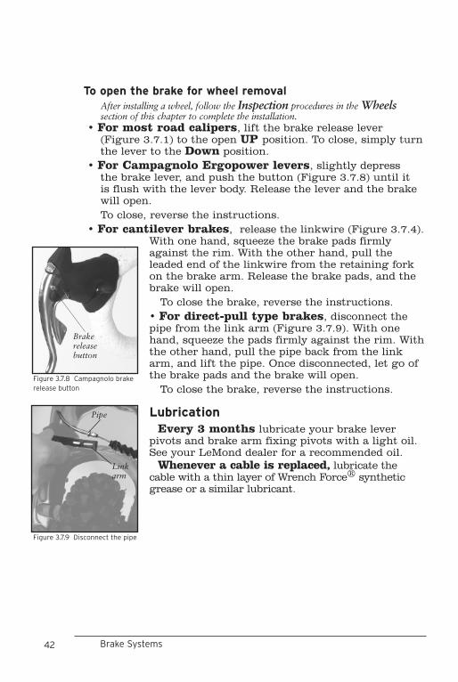
42 43CHAPTER THREE Inspection, Adjustment & Lubrication
To open the brake for wheel removalAfter installing a wheel, follow the Inspection procedures in the Wheels section of this chapter to complete the installation.
• For most road calipers, lift the brake release lever (Figure 3.7.1) to the open UP position. To close, simply turn the lever to the Down position.
• For Campagnolo Ergopower levers, slightly depress the brake lever, and push the button (Figure 3.7.8) until it is flush with the lever body. Release the lever and the brake will open.
To close, reverse the instructions.• For cantilever brakes, release the linkwire (Figure 3.7.4).
With one hand, squeeze the brake pads firmly against the rim. With the other hand, pull the leaded end of the linkwire from the retaining fork on the brake arm. Release the brake pads, and the brake will open. To close the brake, reverse the instructions.• For direct-pull type brakes, disconnect the pipe from the link arm (Figure 3.7.9). With one hand, squeeze the pads firmly against the rim. With the other hand, pull the pipe back from the link arm, and lift the pipe. Once disconnected, let go of the brake pads and the brake will open. To close the brake, reverse the instructions.
LubricationEvery 3 months lubricate your brake lever
pivots and brake arm fixing pivots with a light oil. See your LeMond dealer for a recommended oil.
Whenever a cable is replaced, lubricate the cable with a thin layer of Wrench Force® synthetic grease or a similar lubricant.
Brake Systems
Figure 3.7.8 Campagnolo brake release button
Brake release button
Figure 3.7.9 Disconnect the pipe
Pipe
Link arm
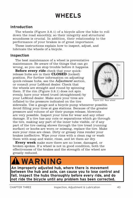
42 43CHAPTER THREE Inspection, Adjustment & Lubrication
IntroductionThe wheels (Figure 3.8.1) of a bicycle allow the bike to roll
down the road smoothly, so their integrity and structural soundness is crucial. In addition, their relationship to the performance of your brakes is of great importance.
These instructions explain how to inspect, adjust, and lubricate the wheels of a bicycle.
InspectionThe best maintenance of a wheel is preventative
maintenance. Be aware of the things that can go wrong, so you can stop trouble before it happens.
Before every ride check that your quick-release hubs are in their CLOSED (locked) position. For further information on adjusting quick-release hubs, see the Adjustment section, or consult your LeMond dealer. Check that the wheels are straight and round by spinning them. If the rim (Figure 3.8.1) does not spin evenly, have your wheel trued (straightened) by your LeMond dealer. Make sure your tires are inflated to the pressure indicated on the tire sidewalls. Use a gauge and a bicycle pump whenever possible. Avoid filling your tires at gas stations. Because of the greater pressure and volume of air their pumps release, blowouts are very possible. Inspect your tires for wear and any other damage. If a tire has any cuts or separations which go through the tire, making any part of the inner tube visible, or if any part of the tire casing shows through the tire tread (running surface) or knobs are worn or missing, replace the tire. Make sure your rims are clean. Dirty or greasy rims render your brakes ineffective. Wipe your rims with a clean rag or wash them with soap and water, rinse, and let them air dry.
Every week make sure there are no loose, damaged, or broken spokes. If a wheel is not in good condition, both the effectiveness of the brakes and the strength of the wheel are greatly reduced.
WHEELS
Figure 3.8.1 Rear wheel
Tire
Rim
Hub
Spokes
WARNINGAn improperly adjusted hub, where there is movement between the hub and axle, can cause you to lose control and fall. Inspect the hubs thoroughly before every ride, and do not ride the bicycle until any problem has been corrected.
44 45CHAPTER THREE Inspection, Adjustment & LubricationWheels
Every month check that both hub bearings are properly adjusted. Lift the front end of the bicycle off the ground with one hand and attempt to move the rim laterally, left to right. Look, feel, and listen for any looseness in the hub bearings. Spin the wheel, and listen for any grinding or other unusual noises. If the hub feels loose or makes any noise, the hub needs an adjustment. Repeat these procedures for the rear wheel.
Every month, check your rims for wear. On adult-size bicycles there may be wear indicators in the braking surface, either a continuous indented band or several small spherical indentations at even intervals around the rim. If the braking surface has worn so that any part of these indicators is no longer visible, have your dealer replace the rim.
Before installing tires make sure a rim strip is in place which completely covers the rim web (wall to wall) so that all spoke holes are completely covered.
Adjustment
To adjust wheel bearingsThis procedure requires special tools and training, so should
only be done by your LeMond dealer.
Quick-release adjustment and closureFor proper and safe adjustment of a quick-release, read and
follow these instructions carefully.
WARNINGMake sure the rim strip covers all of the spoke holes or spoke heads. If they are exposed, the inner tube could be punctured and lose air suddenly causing you to lose control and fall. Make sure the rim strip properly covers all spoke holes.
WARNINGA quick-release that is not properly adjusted and closed may allow the wheel to be loose or come off unexpectedly, causing you to lose control and fall. Make sure the quick-release is adjusted and closed properly before riding the bike.
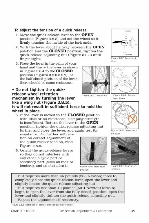
44 45CHAPTER THREE Inspection, Adjustment & Lubrication
To adjust the tension of a quick-release1. Move the quick-release lever to the OPEN
position (Figure 3.8.2) and set the wheel so it firmly touches the inside of the fork ends.
2. With the lever about halfway between the OPEN position and the CLOSED position, tighten the quick-release adjusting nut (Figure 3.8.3) until finger-tight.
3. Place the lever in the palm of your hand and throw the lever as shown in Figure 3.8.4 to the CLOSED position (Figures 3.8.6-3.8.7). At the half-closed position of the lever, there should be some resistance.
• Do not tighten the quick-release wheel retention mechanism by turning the lever like a wing nut (Figure 3.8.5); it will not result in sufficient force to hold the wheel in place.
5. If the lever is moved to the CLOSED position with little or no resistance, clamping strength is insufficient. Return the lever to the OPEN position, tighten the quick-release adjusting nut further and close the lever, and again test for resistance. For further informa-tion on correct adjustment of the quick-release tension, read Figure 3.8.8.
6. Orient the quick-release levers so they do not interfere with any other bicycle part or accessory part (such as rack or fenders), and so obstacles in Figure 3.8.7 Rear lever
positionFigure 3.8.6 Front lever position
����
������
Figure 3.8.4 Proper lever throw
����
����
����
����
Figure 3.8.5 Do not turn the lever
Figure 3.8.3 Tighten nut
If it requires more than 45 pounds (200 Newton) force to completely close the quick-release lever, open the lever and slightly loosen the quick-release adjusting nut.
If it requires less than 12 pounds (53.4 Newton) force to begin to open the lever from the fully closed position, open the lever and slightly tighten the quick-release adjusting nut.
Repeat the adjustment if necessary.Figure 3.8.8 Definition of correct quick-release lever force
����
������
Figure 3.8.2 Lever posi-tions
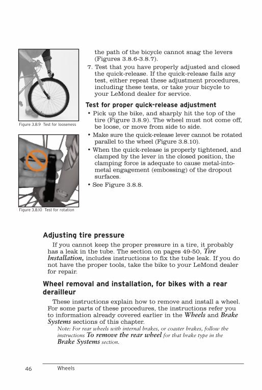
46 47CHAPTER THREE Inspection, Adjustment & Lubrication
the path of the bicycle cannot snag the levers (Figures 3.8.6-3.8.7).
7. Test that you have properly adjusted and closed the quick-release. If the quick-release fails any test, either repeat these adjustment procedures, including these tests, or take your bicycle to your LeMond dealer for service.
Test for proper quick-release adjustment• Pick up the bike, and sharply hit the top of the
tire (Figure 3.8.9). The wheel must not come off, be loose, or move from side to side.
• Make sure the quick-release lever cannot be rotated parallel to the wheel (Figure 3.8.10).
• When the quick-release is properly tightened, and clamped by the lever in the closed position, the clamping force is adequate to cause metal-into-metal engagement (embossing) of the dropout surfaces.
• See Figure 3.8.8.
Figure 3.8.10 Test for rotation
Figure 3.8.9 Test for looseness
Wheels
Adjusting tire pressureIf you cannot keep the proper pressure in a tire, it probably
has a leak in the tube. The section on pages 49-50, Tire Installation, includes instructions to fix the tube leak. If you do not have the proper tools, take the bike to your LeMond dealer for repair.
Wheel removal and installation, for bikes with a rear derailleur
These instructions explain how to remove and install a wheel. For some parts of these procedures, the instructions refer you to information already covered earlier in the Wheels and Brake Systems sections of this chapter.
Note: For rear wheels with internal brakes, or coaster brakes, follow the instructions To remove the rear wheel for that brake type in the Brake Systems section.
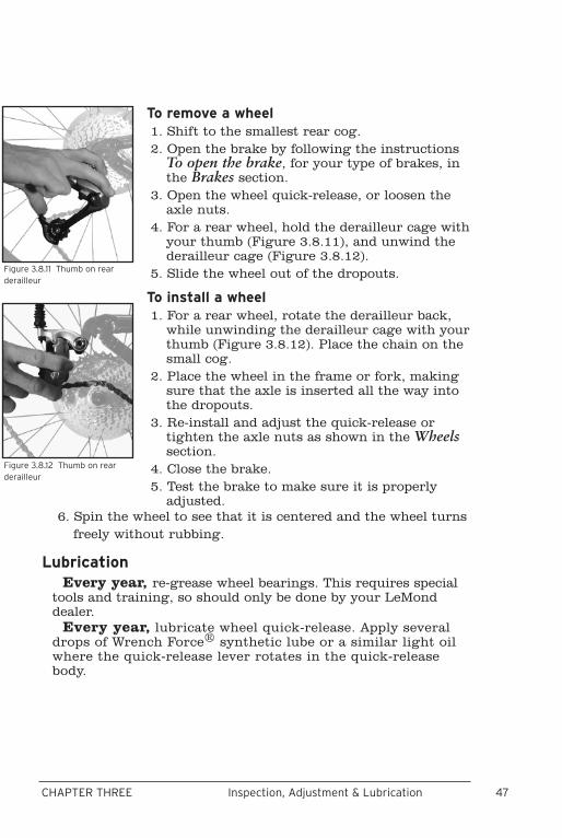
46 47CHAPTER THREE Inspection, Adjustment & Lubrication
To remove a wheel1. Shift to the smallest rear cog.2. Open the brake by following the instructions
To open the brake, for your type of brakes, in the Brakes section.
3. Open the wheel quick-release, or loosen the axle nuts.
4. For a rear wheel, hold the derailleur cage with your thumb (Figure 3.8.11), and unwind the derailleur cage (Figure 3.8.12).
5. Slide the wheel out of the dropouts.
To install a wheel1. For a rear wheel, rotate the derailleur back,
while unwinding the derailleur cage with your thumb (Figure 3.8.12). Place the chain on the small cog.
2. Place the wheel in the frame or fork, making sure that the axle is inserted all the way into the dropouts.
3. Re-install and adjust the quick-release or tighten the axle nuts as shown in the Wheels section.
4. Close the brake. 5. Test the brake to make sure it is properly
adjusted.
Figure 3.8.12 Thumb on rear derailleur
Figure 3.8.11 Thumb on rear derailleur
6. Spin the wheel to see that it is centered and the wheel turns freely without rubbing.
LubricationEvery year, re-grease wheel bearings. This requires special
tools and training, so should only be done by your LeMond dealer.
Every year, lubricate wheel quick-release. Apply several drops of Wrench Force® synthetic lube or a similar light oil where the quick-release lever rotates in the quick-release body.

48 49CHAPTER THREE Inspection, Adjustment & Lubrication
REFLECTORS
IntroductionThe reflectors on your bicycle illuminate when a light is
shone on them, directing some of the light back to the source. In poor lighting conditions, if an oncoming vehicle has their lights on, the reflectors may help the other vehicle see your bike. Reflectors are an important part of your bicycle’s safety equipment. Do not remove the reflectors from your bicycle.
InspectionEvery three months, make sure all the nuts and bolts
holding the front, rear, pedal, and wheel reflectors are tight. Check that front and rear reflectors are oriented so their reflec-tive surfaces are perpendicular to the ground, and that all reflective surfaces are clean and in good condition. The front reflector should point directly forward, and the rear should point directly back. The rear reflector should be at least three inches below the top of the seat.
Schraeder and Presta ValvesThere are two styles of valves used on LeMond
bicycles (Figure 3.8.13), which use different use techniques for inflation: • Schraeder valve- remove the valve cap, attach an air pump with a Schraeder fitting, and inflate. Put the cap back on, as the cap keeps dirt and debris out of the valve.• The Presta valve is also known as a French valve. To inflate a Presta valve, remove the valve cap, if present. Presta valves seal very tightly, and require a lot of pressure to open them initially, so after unscrewing the valve nut, depress the nut with your finger to open the valve. This should let a little air out. Inflate using a Presta
valve fitting. After inflation, tighten the valve nut against the valve stem until finger-tight. This provides the same function as the valve cap on a Schraeder valve.
Figure 3.8.13 Valve stem types
Schraeder Presta
Wheels
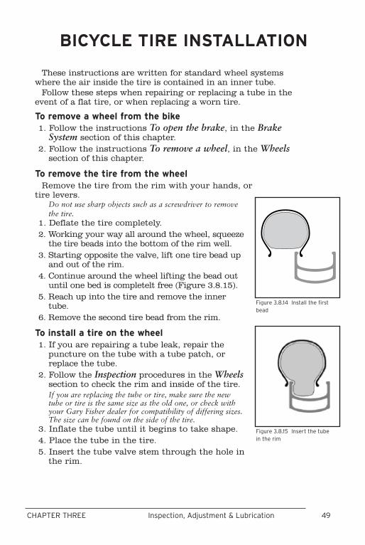
48 49CHAPTER THREE Inspection, Adjustment & Lubrication
These instructions are written for standard wheel systems where the air inside the tire is contained in an inner tube.
Follow these steps when repairing or replacing a tube in the event of a flat tire, or when replacing a worn tire.
To remove a wheel from the bike1. Follow the instructions To open the brake, in the Brake
System section of this chapter.2. Follow the instructions To remove a wheel, in the Wheels
section of this chapter.
To remove the tire from the wheelRemove the tire from the rim with your hands, or
tire levers. Do not use sharp objects such as a screwdriver to remove the tire.
1. Deflate the tire completely. 2. Working your way all around the wheel, squeeze
the tire beads into the bottom of the rim well.3. Starting opposite the valve, lift one tire bead up
and out of the rim.4. Continue around the wheel lifting the bead out
until one bed is completelt free (Figure 3.8.15).5. Reach up into the tire and remove the inner
tube.6. Remove the second tire bead from the rim.
To install a tire on the wheel1. If you are repairing a tube leak, repair the
puncture on the tube with a tube patch, or replace the tube.
2. Follow the Inspection procedures in the Wheels section to check the rim and inside of the tire.If you are replacing the tube or tire, make sure the new tube or tire is the same size as the old one, or check with your Gary Fisher dealer for compatibility of differing sizes. The size can be found on the side of the tire.
3. Inflate the tube until it begins to take shape. 4. Place the tube in the tire. 5. Insert the tube valve stem through the hole in
the rim.
BICYCLE TIRE INSTALLATION
Figure 3.8.15 Insert the tube in the rim
Figure 3.8.14 Install the first bead
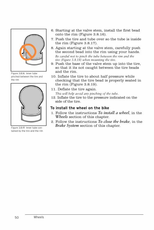
50 51CHAPTER THREE Inspection, Adjustment & Lubrication
6. Starting at the valve stem, install the first bead onto the rim (Figure 3.8.16).
7. Push the tire and tube over so the tube is inside the rim (Figure 3.8.17).
8. Again starting at the valve stem, carefully push the second bead into the rim using your hands. Be careful not to pinch the tube between the rim and the tire (Figure 3.8.18) when mounting the tire.
9. Push the base of the valve stem up into the tire, so that it its not caught between the tire beads and the rim.
10. Inflate the tire to about half pressure while checking that the tire bead is properly seated in the rim (Figure 3.8.19).
11. Deflate the tire again. This will help avoid any pinching of the tube.
12. Inflate the tire to the pressure indicated on the side of the tire.
To install the wheel on the bike1. Follow the instructions To install a wheel, in the
Wheels section of this chapter.2. Follow the instructions To close the brake, in the
Brake System section of this chapter.Figure 3.8.19 Inner tube con-tained by the tire and the rim
Wheels
Figure 3.8.16 Inner tube pinched between the tire and the rim

50 51CHAPTER THREE Inspection, Adjustment & Lubrication
LeMond bicycle frames are constructed from a variety of high performance materials. For safe operation, and long life, take care of your bike frame by following these instructions.
InspectionBefore every ride carefully inspect your frameset (frame
and fork) for signs of fatigue. Scratches, cracks, dents, deformation, or discoloration are signs of stress-caused fatigue. If any part shows signs of damage or fatigue, replace the part before riding the bicycle.
Frame information- all framesLeMond framesets use seat lugs designed to accept seat
posts with 27.12 to 27.20 mm outer diameter. According to the specifications for your frame, the seatpost should be measured for conformity to this tolerance prior to installation.
For titanium, aluminum, or steel frames, lubricate the seatpost to prevent seizing in the frame. Do not lubricate a seatpost in a frame with an OCLV seattube; inside the seat lug of frames with OCLV, a thin layer of fiberglass acts as an insulator to prevent corrosion.
The titanium, aluminum or OCLV carbon fiber composite parts of your bicycle, both frame tubes and parts like rockers or dropouts, are not as ductile as steel. Attempting to make adjustments to a titanium, aluminum, or OCLV part by bending or twisting it poses a risk of breaking it. Readjustment of titanium, aluminum, or OCLV frame alignment is not recommended.
Tolerances for press fits and thread fits are critical. Pressing a part which is too large, or misaligned, may break the frame or part. Over-torquing a threaded fastener may ruin the threads or break the part. Be sure bottom bracket and rear derailleur threads are clean and well greased before insertion. Start threads by hand, not with a wrench. Torque specifications for bottom bracket cup threads is 430-610 lb•in (48.6-68.9
CARE OF YOUR FRAME OR FORK
WARNINGNever modify your frameset or parts in any way, including sanding, drilling, filing, removing redundant retention devices, installing incompatible forks, or by any other method. An improperly modified frame, fork, or component can cause you to lose control and fall.
52 53CHAPTER THREE Inspection, Adjustment & Lubrication
Nm). Torque specifications for rear derailleur threads is 70-85 lb•in (7.9-9.6 Nm).
When cleaning frame parts, do not use solvents or harsh chemicals. Remove road film with a soft rag and a mild detergent and water solution. Use of industrial solvents for cleaning or paint removal may damage the paint.
Removing paint from any frameset requires special techniques and great care. Harsh abrasives will remove frame material, possibly weakening the bicycle. See your LeMond dealer for more information.
Excessive heat, such as that used in powder coating, or any open flame, may damage the adhesive which joins the frame parts. Do not exceed 180º F. (82º C.) exposure to your frame.
Modifying the frame in any way will void the warranty and may be unsafe.
Changing the forks on your bicycle could alter the steering of the bicycle, or create undesirable stress loads on the frame. Suspension forks may add stress to a bike frame. Never add a suspension fork to a road bike, or change style and/or length of forks. If you must replace the fork on any bike, check with your dealer or the LeMond Bicycles technical service depart-ment to ensure that the new forks are compatible with the frame.
Special OCLV road frame and fork requirementsBontrager carbon composite forks are not compatible with
any mechanism which clamps around the fork blade, with the exception of bicycle computer sensors. Do not use mechanical fasteners to attach any other parts to this fork. If you are unsure of what items can be attached to this fork, consult your Bontrager dealer.
Frame RepairMost types of frame damage may be repaired at the LeMond
factory. You must send your frame back to LeMond through an authorized LeMond dealer.
Care of Your Frame or Fork

52 53CHAPTER THREE Inspection, Adjustment & Lubrication

54
LEMOND BICYCLES LIMITED WARRANTY
LeMond Bicycles warrants each new LeMond bicycle frame and rigid fork against defects in workmanship and materials for the lifetime of the original owner. LeMond Bicycles likewise warrants all original parts for a period of one year from the date of purchase. Paint and decals are warranted for one year. This warranty is expressly limited to the repair or replace-ment of a defective frame, fork, or defective part and is the sole remedy of the warranty. This warranty applies only to the original owner and is not transferable.
Claims under this warranty must be made through an authorized LeMond dealer. Proof of purchase is required. A warranty registration card must be completed and received by LeMond Bicycles before a warranty claim may be processed.
The warranty does not cover normal wear and tear, improper assembly or follow-up maintenance, or installation of parts or accessories not originally intended or compatible with the bicycle as sold.
The warranty does not apply to damage or failure due to accident, misuse, abuse, or neglect. Modification of the frame or components shall void this warranty.
LeMond Bicycles shall not be responsible for incidental or consequential damages. Some states do not allow the exclusion of incidental or consequential damages, so the above exclusion may not apply to you. Labor charges for parts changeovers are not covered by the warranty.
This warranty gives the consumer specific legal rights, and those rights may vary from place to place. This warranty does not effect the statutory rights of the consumer.