BIKE BRAKE LEVER DESING-Continuum Mechanicsdocs.gestionaweb.cat/0761/bike-brake-lever.pdfBIKE BRAKE...
49
BIKE BRAKE LEVER DESIGN Continuum Mechanics Alumns: Fargas Cabanillas, Josep Maria Olivé Delgado, Roger Sansalvadó Cabonés, Clara Teacher: Bonada Bo, Jordi 3 th of December 2013
Transcript of BIKE BRAKE LEVER DESING-Continuum Mechanicsdocs.gestionaweb.cat/0761/bike-brake-lever.pdfBIKE BRAKE...

BIKE BRAKE LEVER
DESIGN
Continuum Mechanics
Alumns:
Fargas Cabanillas, Josep Maria
Olivé Delgado, Roger
Sansalvadó Cabonés, Clara
Teacher:
Bonada Bo, Jordi
3th of December 2013

BIKE BRAKE LEVER DESING-Continuum Mechanics
Page 2
INDEX
1. MATERIALS, SOLICITATIONS, INFORMATION RESEARCH AND
PRELIMINARY DESING. ................................................................................... 3
1.1 Basic function and working key points. ................................................................. 3
1.2. Materials selection: availability, difficulty to shape it, resistant and elastic
characteristics, density, cost, assays ........................................................................... 6
1.2.1. Material options: ............................................................................................................. 6
1.2.2 Material Selection / decision ............................................................................................ 8
1.3 Maximum permissible force, dispersion and characteristic values.................... 10
1.4 Basic geometric specifications. Preliminary design and prototype construction
....................................................................................................................................... 16
2. Finite elements method ...................................................................... 18
2.1 Limitations of the model, boundary conditions, idealization and numeric
singularities .................................................................................................................. 18
2.2. Characteristics of the model: finite elements type, material model, mesh ....... 20
2.3. Results reliability: refined meshing ..................................................................... 23
2.4. Infinitesimal displacement hypothesis, nonlinear calculation ........................... 27
3. Results analysis ....................................................................................... 28
3.1. Current displacement ............................................................................................ 28
3.2. Principal strength distribution.............................................................................. 30
3.3. Failure criteria. Equivalent stress distribution .................................................... 32
3.4. Security coefficient and load at failure ................................................................ 34
3.4.1 Security coefficient ........................................................................................................ 34
3.4.2 Load at failure ................................................................................................................ 34
4. Optimization of the design, construction, test and conclusions ............ 35
4.1 Optimization of the design and final results ......................................................... 35
4.1.1 Optimization process ..................................................................................................... 35
4.1.2 Refining mesh process .................................................................................................. 39
4.1.3 Current displacement .................................................................................................... 40
4.1.4 Linear VS nonlinear calculus ......................................................................................... 40
4.1.5 Principal stress directions .............................................................................................. 42
4.1.6 Security coefficient ........................................................................................................ 43
4.1.7 Reaction force ............................................................................................................... 44
4.2 Final design and building process ........................................................................ 45
4.3. Environmental impact and bill .............................................................................. 47
5. Test and conclusions ............................................................................... 48
6. References ............................................................................................... 49
BIKE BRAKE LEVER DESING-Continuum Mechanics
Page 3
1. MATERIALS, SOLICITATIONS, INFORMATION RESEARCH AND
PRELIMINARY DESING.
1.1 Basic function and working key points.
The basic function of brake levers is to activate the brake mechanism, which allows people to slow down or stop while they are riding a bike. There are two types of mechanism: mechanic brakes or hydraulic, and both functioning and effectiveness are really different. Also there are differences between all kind of modalities there are in the world of biking, without taking into account if they are hydraulic or mechanic and different kind of materials, depending on the quality of them.
The functioning of brake levers is very simple. If we talk about a mechanic brake lever, first of all we need to push it. This action stretches a metallic sane that permits the two brake pads put pressure on one of the two wheel rims. The functioning of hydraulic brakes is a bit different. Here in order to stop the bike, the brake lever pushes special oil making pressure and making the bike slow down or stop. The task that brake levers have to carry out makes them to reach some essential properties. So they have not only hardness and stiffness but also lightness and resistance. And this has a simple explanation; these levers have to be able to support an extremely hand-push without breaking or deforming, so they make possible for people to slow down the bike without any danger.
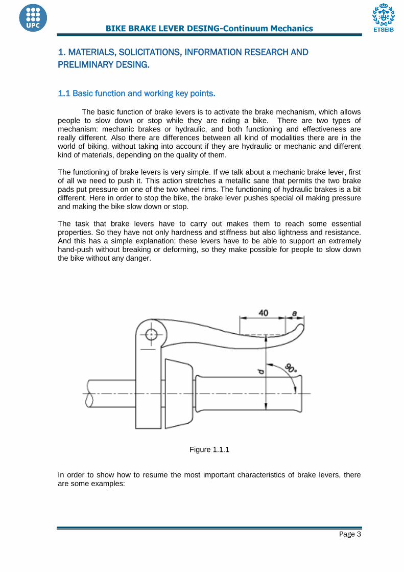
Figure 1.1.1
In order to show how to resume the most important characteristics of brake levers, there are some examples:

BIKE BRAKE LEVER DESING-Continuum Mechanics
Page 4
SRAM FORCEDOUBLE TAP CONTROLS Weight: 302g
Speeds: 10 rear Technology Highlights:
DobuleTapwith
ZeroLossTMonthefront Material: Carbon Brake Lever, Magnesium Shift Lever, Titanium Price: 444€
ML940 (MTB)
Weight: 74grams/wheel Technology:
Super Lightweight Ergonomic lever design Stainless steel hardware 2 finger lever blade For use with Rapid Fire shifters
Materials: Full carbon fiber lever and alloy
bracket Colour: Carbon Price: 110.99$
RL879 (TRI/TT)
Weight: 77 grams/wheel Technology:
Ergonomic lever design
Pivoting cable stop to minimize cable friction
For use with caliper or canti brakes
Expanding plug clamp style
Internal cable routing
Return spring Material: Aluminium body and lever blade Colour: Black or silver For use with: 19-20.6mm ID aero bars Price: 59.99$
BX4 Mag (BMX) Weight: 83grams/wheel
Technology: Right hand only Precision forged magnesium blade One finger trigger lever 0.8mm triple coiled return spring 10mm barrel adjuster Adjustable reach
Materials: Magnesium, Titanium
Color: Ti Silver Price:29.99$

BIKE BRAKE LEVER DESING-Continuum Mechanics
Page 5
Brake levers for rear and forward brakes have to be placed in the correct way corresponding to the country’s legislation or the habits of the country in what the bike is sold. The manufacturer must indicate how to activate the rear and forward brakes. In relation with dimensions, the maximum grip dimension, d, measured between the outer surfaces of the brake lever in the designated area that contact with rider’s finger and handlebars or other coating materials, over a distance exceeding 40 mm, as shown in the figure 1.1.1, should not exceed: 90 mm on bicycles that the saddle can be adjusted to provide a maximum height greater than 635mm and 75 mm on bicycles that the saddle can be adjusted to provide a maximum height lower than 635mm.
BIKE BRAKE LEVER DESING-Continuum Mechanics
Page 6
1.2. Materials selection: availability, difficulty to shape it, resistant and elastic
characteristics, density, cost, assays
1.2.1. Material options:
To design the bike brake lever, we need to choose the material we want to use
depending on how easy we can get it, the price we would need to pay for it and the
properties we need from it. Choosing the material is the first step in this project because the
design of the brake lever will depend on this decision. After some research, these are our
different material options:
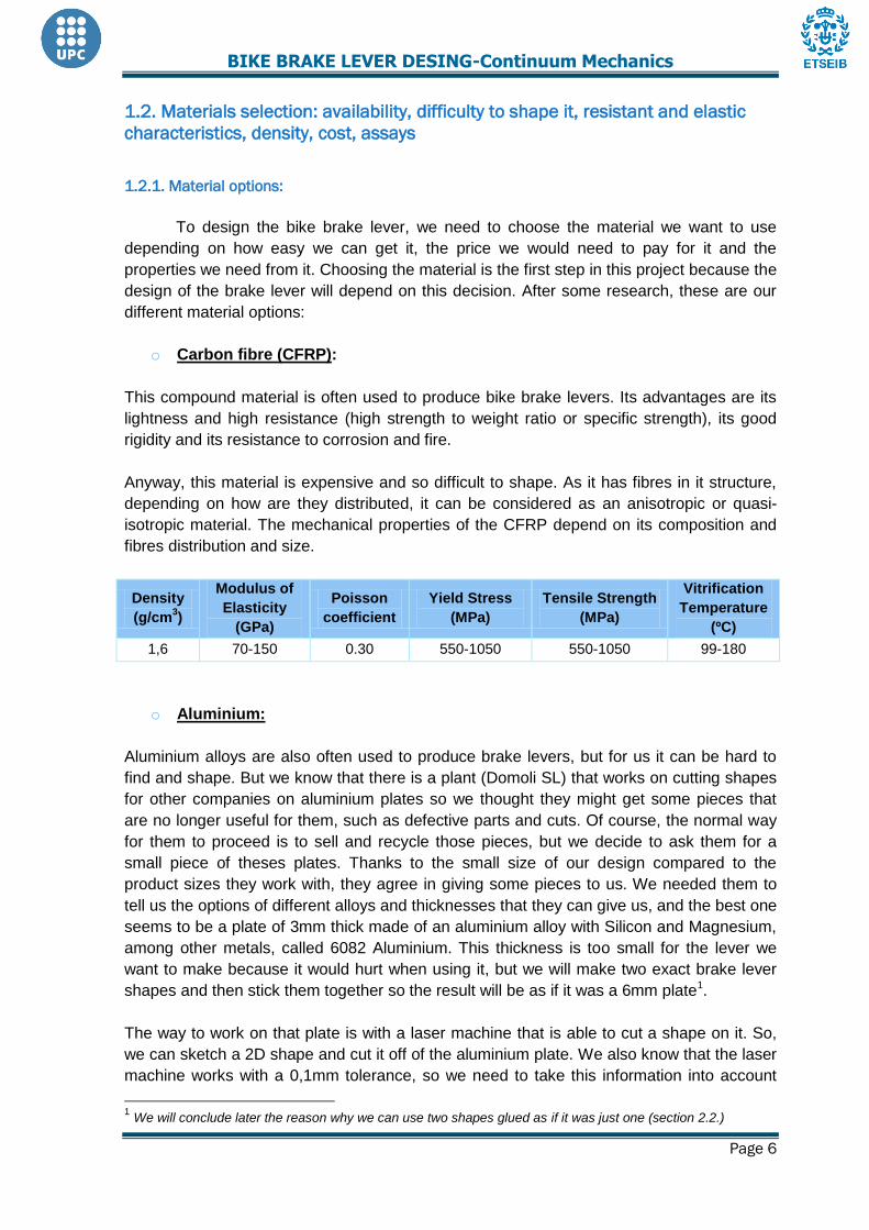
o Carbon fibre (CFRP):
This compound material is often used to produce bike brake levers. Its advantages are its
lightness and high resistance (high strength to weight ratio or specific strength), its good
rigidity and its resistance to corrosion and fire.
Anyway, this material is expensive and so difficult to shape. As it has fibres in it structure,
depending on how are they distributed, it can be considered as an anisotropic or quasi-
isotropic material. The mechanical properties of the CFRP depend on its composition and
fibres distribution and size.
Density
(g/cm3)
Modulus of
Elasticity
(GPa)
Poisson
coefficient
Yield Stress
(MPa)
Tensile Strength
(MPa)
Vitrification
Temperature
(ºC)
1,6 70-150 0.30 550-1050 550-1050 99-180
o Aluminium:
Aluminium alloys are also often used to produce brake levers, but for us it can be hard to
find and shape. But we know that there is a plant (Domoli SL) that works on cutting shapes
for other companies on aluminium plates so we thought they might get some pieces that
are no longer useful for them, such as defective parts and cuts. Of course, the normal way
for them to proceed is to sell and recycle those pieces, but we decide to ask them for a
small piece of theses plates. Thanks to the small size of our design compared to the
product sizes they work with, they agree in giving some pieces to us. We needed them to
tell us the options of different alloys and thicknesses that they can give us, and the best one
seems to be a plate of 3mm thick made of an aluminium alloy with Silicon and Magnesium,
among other metals, called 6082 Aluminium. This thickness is too small for the lever we
want to make because it would hurt when using it, but we will make two exact brake lever
shapes and then stick them together so the result will be as if it was a 6mm plate1.
The way to work on that plate is with a laser machine that is able to cut a shape on it. So,
we can sketch a 2D shape and cut it off of the aluminium plate. We also know that the laser
machine works with a 0,1mm tolerance, so we need to take this information into account
1 We will conclude later the reason why we can use two shapes glued as if it was just one (section 2.2.)

BIKE BRAKE LEVER DESING-Continuum Mechanics
Page 7
when we design the shape to be cut. For sure, that plant knows exactly the mechanical
properties of the aluminium they work with and they have told us the alloy data that we
need to model the brake lever made of this material. Another consideration is specifically
the restrictions on shape that the process of cutting has itself thus our shape design has to
be made just with lines and circles. Anyway, we will look for other information and compare
those given values. The only thing we will need to pay for is for the machine to cut our
sketch onto the plate, which will be more or less 30€.
It is important to highlight that aluminium is quite hard to break by applying forces on it
because of its tenacity. Before it happens, it gets plastically deformed. The bright side of
this fact is that it is the best option for a real brake lever, when you need to look for safety
for the people riding the bike with that brake. If they pushed it so hard to stop in an
emergency situation, and it broke, they would get hurt. So, it is much better to make sure
that in case someone applied more pressure than the limit considered, no one would get
hurt. By the way, the bad part of that fact is that it is more difficult to know the exact stress
that makes it get deformed. This makes more difficult to draw conclusions when assaying
pieces made of this material. Anyway, nowadays there are methods to get that exact
information, such as pressure sensors.
Some mechanical properties of the 6082 aluminium (T6) are:
Density
(g/cm3)
Modulus of
Elasticity
(GPa)
Poisson
coefficient
Yield
stress
(MPa)
Melting point
(ºC)
Break load
(MPa)
2,7 70 0.33 260 555 310
o Methacrylate:
Methacrylate is not used to produce real brake levers, but besides the options of materials
that are common for this purpose, we need to consider materials that can be useful options
for our project. The methacrylate option is so similar to the aluminium one. The only
differences are, of course, the material properties, and that we will be able to choose the
thickness we like the most from 2mm to 10mm. Moreover, the methacrylate cannot be
blended when it is cold, so it can be interesting and easier to measure how it breaks than if
it would get plastically deformed (like what happens with aluminium).
Moreover, even though it is lighter than the aluminium, it is not as resistant as a 6xxx alloy
of aluminium.
Density
(g/cm3)
Melting
point
(ºC)
Softening
temperature
(ºC)
Tensile
Strength
(MPa)
Elongation
at fracture
(%)
Poisson
coefficient
Modulus
of
elasticity
(GPa)
1,19 200-230 105-120 72-80 4-5.5 0.45
3.2-3.3

BIKE BRAKE LEVER DESING-Continuum Mechanics
Page 8
o Boxwood:
By choosing this option, we have some advantages on making the wanted shape we like to.
Thanks to a carpenter that would help us and model the wood, we can make a 2D sketch
and cut it off with the thickness we like; but moreover we have the option to draw a more
complex sketch, in 3D, and make it of wood. Usually, wood it is not a good option to make
pieces you will need to model and simulate it because of its anisotropy. This characteristic
leads to mistakes and differences of the results expected and the physic reality. This
happens because wood properties are different depending on the direction due to the fibres
is has. Actually, we can use some different kinds of wood, but we decide that boxwood is
the best wood option that we can afford because its anisotropy is not so bad, and it is a
strong and quite light material. The properties of the boxwood are:
Density
(g/cm3)
Modulus of
Elasticity
(GPa)
Bend
strength
(MPa)
Crushing
strength
(MPa)
Tensile
Strength
(MPa)
Poisson
coefficient
Janka
hardness
(N)
0,885-
0,960
12-14 (fiber
direction) 144.5 68.6 86-112
0.318-0.424
12.610
o Other options:
We also think of two other options: The first one is using Rapid Prototyping. By this method our hand brake lever can be done form a 3D sketch and the result will be good. The other option is printing a 3D hand brake with a plastic material. The disadvantage of this method is the way those printers work. Our piece will not be as a solid one, for example made by plastic injection moulding; it will look all made of fibres. That makes that the difference between the results on the simulation and what is really happening will be too big.
1.2.2 Material Selection / decision
CFRP: We think this material is a good option to produce brake levers although for this
project is not a good idea because it is too hard to shape and too expensive.
Aluminium: This is the material we will use for our project. Although we know we will need
to pay to get our brake lever made of aluminium, we think that it is the best option due to
the good properties it has, like its resistance compared to its weight and corrosion
resistance, and it would be a good option too for a real brake lever.
Methacrylate: If we were not able to get the aluminium plate, it might be the best option for
this project.
Boxwood: It is mainly its anisotropy that makes us think it is not a good option because our
results can be wrong or very different from the test results.

BIKE BRAKE LEVER DESING-Continuum Mechanics
Page 9
Other options: Both of them are impractical in spite of some good aspects they would
have.
The Rapid Prototyping method is so good, and the result convinces us, but it is too
expensive for us to afford it and would take too much time. And the reason why we do not
think that 3D printing is a good method is because we would have wrong conclusions for
our hand brake lever design due to the fibrous structure that the lever would have and
because it is a weak material.
In conclusion, what we will use for our project is a plate of an aluminium alloy called AW
6082 T6 of 3mm thick.

BIKE BRAKE LEVER DESING-Continuum Mechanics
Page 10
1.3 Maximum permissible force, dispersion and characteristic values.
To design our brake lever was important to know the maximum strength a man can
do with one hand. That is because we want to make sure that this man riding the bike with
our brake lever will not be able to break it just trying to make the bike stop for example in an
emergency situation. But on the other hand, it is important to know the strength that this
same man riding the bike in normal conditions would usually do to stop. This means, the
hand brake lever must resist the maximum strength one man can do with one hand, for
example, if he is in a risk situation and because he is scared he makes much more strength
than necessary. But the normal strength to make the brake work must be comfortable for
the man riding the bike. So, if someone using the bike wants to stop, the strength he must
need must be a little high so he will only stop on purpose, but not that high that he would
get tired by using the brakes.
It is important to highlight here that our decisions will be different doing this project than
they would be if doing a real project design. This is due that we will not use the same data
than we would because we want to be able to test the lever and compare the results with
those we will get by simulation. So all along this section we will distinct the values we would
use for a real design of a brake lever, and the values we decide to use for our prototype.
First of all, in this section we will try to find out the maximum force that a person can grip
strength. The idea is getting an empirical statistical study and we will see what the result is.
The best way to do it is with a tool called Jamar hydraulic Dynamometer (Figure 1.3.1.).
With this machine someone just grip strength and we get the force value he is doing. The
problem is that a Jamar hydraulic Dynamometer costs about one thousand euros. Then we
have two options: on one hand we can try to design an experiment that gets us an idea of
this force. On the other hand we can look for other studies that have been done before.
Figure 1.3.1
First we designed an easy experiment. We took metallic recipient with a handle and we put
it on a scale. The idea then was to start filling the recipient with dense materials like iron
and start to increase the weight. Then the subject had to rise up the recipient with the
fingers but supporting the hand palm on a table, for example. In this way, we got the
maximum weight that the subject is able to rise up, what is proportional to the maximum

BIKE BRAKE LEVER DESING-Continuum Mechanics
Page 11
force that this person can grip strength. We tried with one member of our group and the
maximum weight with one hand was 40kg ergo 392 N.
This type of experiment is really difficult to carry out because of the waste of time placing
and moving weight of the recipient. The maximum force depends also if the palm is more or
less near to the handle and the height of the support itself. So we decided to explore the
other option and try to obtain more data from external sources.
We found out three studies and we joined them together to get the data (Table 1 and Table
2 and 3). This data fits very well with the only one experiment that we did, what mean it was
valid.
Table 1: Obtained from General Motors España
Tables 2 and 3: Obtained from Congreso Internacional de Ergonomía SEMAC
At this point we need to distinct the force value we would use for a real project and the
value we will actually take. If it was a real project, we would like to be sure that the

BIKE BRAKE LEVER DESING-Continuum Mechanics
Page 12
probability of the brake lever to get broken is minimal. For this reason we would use a force
value that the 95% of the population is not able to do. To get this value we need to use
some statistics combined with the data of the studies we found. As we are looking for the
maximum force it needs to bear, we will use male dominant hand force values because
they represent the maximum resistance risk. From those we get the results on Figure 1.3.2.
Figure 1.3.2
Only a 5% of the population can grip strength 535,7 N (54,7 Kg) or more, so if we designed
a brake lever prepared to bear this force (or even the value added to a margin of safety),
the probability of someone breaking it is very small. Anyway, for our project we want a force
value that our team members are able to do so that allows us to test the simulation results.
This is often a good way to proceed: Make a simulation with values you will be able to test
with and check if the real results coincide with the simulation ones. If this happens, it means
that the simulation is right so you can proceed and trust the results you will obtain with the
limit values that you will not test with.
So at this point we decide that, even thought we would use Fmax = 535,7 N, we will take
Fmax = 392 N because this is the maximum force we are able to do. So the way to design
our brake lever is making it resistant to this strength but we will need to make it to get
broken with a stress a little bit higher.
The other part of the information we needed was the comfortable stress that someone
riding a bike should make to stop. To know the normal strength that is necessary for a
normal ride, we made our own experiments. We needed a chronometer, a bike, a bag,
something to write on the floor (chalk) and some weights. We repeated each experiment
three or more times to make sure the results were good enough. We draw with chalk two
lines on the floor separated 10m one from the other.
0,005
0,004
0,003
0,002
0,001
0,000
Force (N)
De
nsit
y
535,7
0,05
397,5
Mean=397,5 N; StDev=84 N
Grip strenght force distribution

BIKE BRAKE LEVER DESING-Continuum Mechanics
Page 13
Figure 1.3.3.
We needed some basic information about the experiment so that we could use the results
for other situations. This was:
The rider came trying to pedal at a constant speed. We made the
chronometer start when he crossed the first line and stopped it at the second
line. With this information we were able to find out what the speed of the bike
for our experiment was.
10 metres in 2,8 seconds thus v=3,57 m/s
Brake system of the bike by brake pads
Another important thing was the weight of the boy riding the bike.
M = 80kg
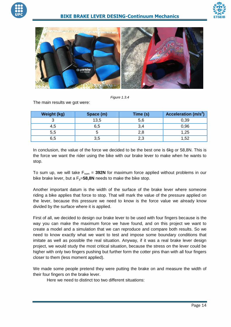
We turned around the front brake lever of the bike and fix an empty bag on it. The reason
why we fixed the bag was so it would not move and the pressure would always work on the
same surface. The handles of the bag, fixed one next to the other, had a width similar to a
human hand. We looked for this fact to happen to make sure that the pressure made would
affect the same way as if someone riding the bike would push the brake lever (Figure 1.3.3.
and Figure 1.3.4.).
The next step was simulating a stop the rider would feel comfortable with. The rider came
pedalling and at the first line he started to stop as he would do it if it was not an experiment.
We noted down what the time and distance were.
The results were: 4 meters and 3 seconds thus a ≈ 1,55 m/s2
We put some weight inside the bag and note down its total weight. When the rider crossed
the first line, instead of using the brake by him, he had to drop the bag and this bag was the
one in charge of making the bike stop.
BIKE BRAKE LEVER DESING-Continuum Mechanics
Page 14
Figure 1.3.4
The main results we got were:
Weight (kg) Space (m) Time (s) Acceleration (m/s2)
3 13,5 5,6 0,39
4,5 6,5 3,4 0,96
5,5 5 2,8 1,25
6,5 3,5 2,3 1,52
In conclusion, the value of the force we decided to be the best one is 6kg or 58,8N. This is
the force we want the rider using the bike with our brake lever to make when he wants to
stop.
To sum up, we will take Fnom = 392N for maximum force applied without problems in our
bike brake lever, but a Fp=58,8N needs to make the bike stop.
Another important datum is the width of the surface of the brake lever where someone
riding a bike applies that force to stop. That will mark the value of the pressure applied on
the lever, because this pressure we need to know is the force value we already know
divided by the surface where it is applied.
First of all, we decided to design our brake lever to be used with four fingers because is the
way you can make the maximum force we have found, and on this project we want to
create a model and a simulation that we can reproduce and compare both results. So we
need to know exactly what we want to test and impose some boundary conditions that
imitate as well as possible the real situation. Anyway, if it was a real brake lever design
project, we would study the most critical situation, because the stress on the lever could be
higher with only two fingers pushing but further form the cotter pins than with all four fingers
closer to them (less moment applied).
We made some people pretend they were putting the brake on and measure the width of
their four fingers on the brake lever.
Here we need to distinct too two different situations:

BIKE BRAKE LEVER DESING-Continuum Mechanics
Page 15
If we were trying to make a real brake lever design, we would take a hand width smaller
than the 95% of the population for sure exceeds. That is because the pressure applied, with
the same force value, is highest if the surface where it is applied is small. So the most
critical working point that we would need the lever to bear would be the one with the
maximum force we told before (565 N) and the minimal width. This is the way that, added to
the margin of safety, we would make sure that our brake lever would not get broken by
someone riding the bike.
So we make some statistic with the hand width data we took and we get this:
0.6
0.5
0.4
0.3
0.2
0.1
0.0
X
De
nsit
y
5.725
0.05
6.942
Distribution PlotNormal; Mean=6.942; StDev=0.74
Figure 1.3.5
So we get that the critical point is when the width is 5,725 cm (Figure 1.3.5.). The
probability of someone applying the maximum force we are working with (40 kg) or more in
less than this width is so small that we can ignore it.
By the way, in this project we want to predict what will happen on the test with our
prototype. For this reason we are using data values that we will be able to test with. So, for
the same reason we will use 392N instead of 535,7N, we will use our team members hand
width, what is, approximately, 70mm.
So finally, we know the data needed for our simulation: Moreover the boundary conditions,
we need to impose on our simulation a pressure of 40*9,8/70*6 = 0,93 MPa (the lever
thickness is 6mm) and because we suppose a uniform pressure and perpendicular to the
surface.
Descriptive Statistics: Width Variable N N* Mean SE Mean StDev Variance Minimum Q1 Median Q3 Maximum
amplada 33 0 6.942 0.129 0.740 0.548 5.500 6.450 7.000 7.500 9.000

BIKE BRAKE LEVER DESING-Continuum Mechanics
Page 16
1.4 Basic geometric specifications. Preliminary design and prototype
construction
Making the brake lever design is an iterative process because we do not know at first how
the pressure applied affects it. So we will need to make a simple design and use the
ANSYS software for a simulation. With the results we will get we will see the parts of the
lever that need to be stronger or that parts that do not support any stress. With this
information we will be able to optimize the design and try again the simulation.
Anyway, there are three factors we know that will matter for the design:
The material, because of its properties such the modulus of elasticity, the Poisson
coefficient and the tensile strength.
The pressure applied, what means the force made and the width of the surface
where this force will be applied.
The part of the brake lever where this pressure will be applied and how close of the
cotter pins is.
The first point is something we have already chosen and cannot change it to make it better
or worse. The second point is information we already know, but we cannot change it either.
The third point is someone we can decide and change to optimize our design at the same
time as the rest of the shape.
So to have some data to analyse and optimize the design, we need to make a preliminary
brake lever design using SOLIDWORKS. We are using SOLIDWORKS instead of drawing
in ANSYS because we can control much better the design tools and we can save the model
and keep improving it.
On this preliminary model we only impose the given restrictions, some parameters that are
already fixed (Figure 1.4.1). It is important to make sure that all changes we will be doing on
our design make it meet the criteria, as the holes diameter where the cotter pins will be, or
the distance between the lever and the handlebar.
Figure 1.4.1
BIKE BRAKE LEVER DESING-Continuum Mechanics
Page 17
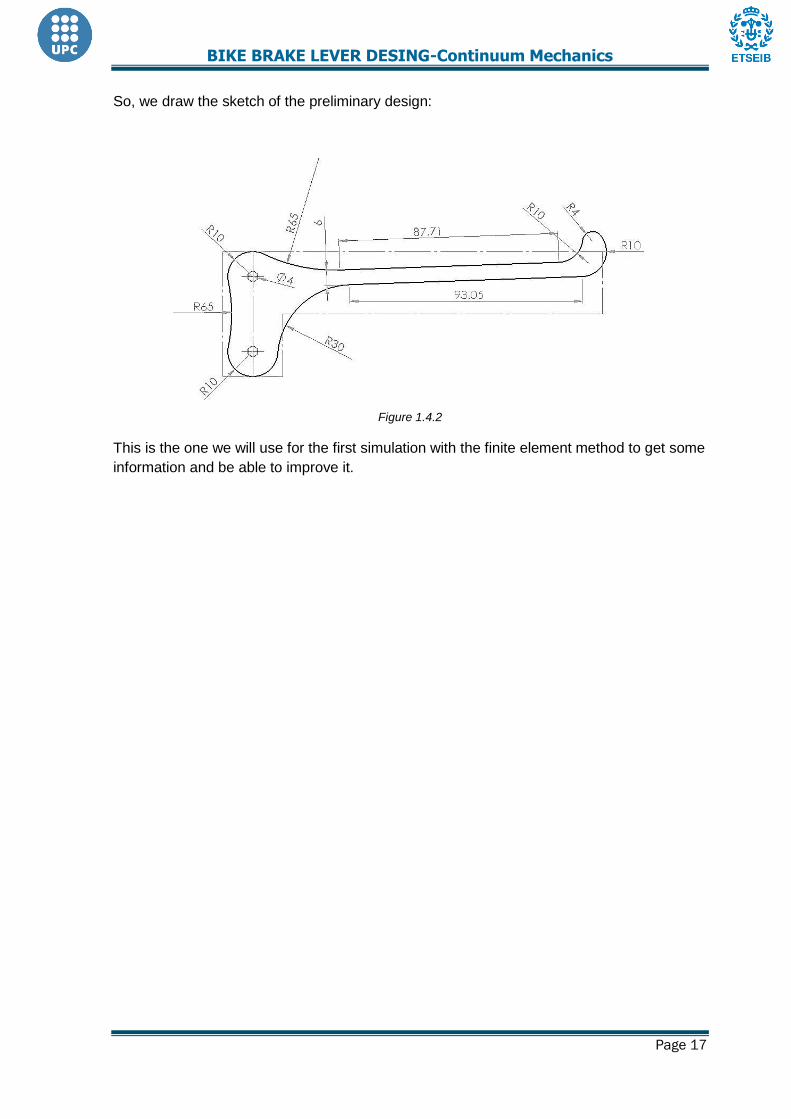
So, we draw the sketch of the preliminary design:
Figure 1.4.2
This is the one we will use for the first simulation with the finite element method to get some
information and be able to improve it.

BIKE BRAKE LEVER DESING-Continuum Mechanics
Page 18
2. Finite elements method
2.1 Limitations of the model, boundary conditions, idealization and numeric
singularities
So the next step is to import this file of the preliminary design to ANSYS and start the
simulation. It is important to highlight that we can assume that the stress on the lever will be
the same in every layer all along the thickness. This is the reason why we can do the
simulation as a 2D shape with thick instead of a 3D situation.
In order to analyse this static situation in ANSYS it is needed to define some boundary
conditions, trying to represent the reality as maximum as possible. It is important too to
make sure that the results do not depend on these boundary conditions.
Figure 2.1.1
In static situation it is known that the total sum of forces and moments is zero. Analysing the
moments, the point P it is used to express them.∑ and ∑
.
Now, in the image that we have seen before, we have ∑ , where T is the
force make by the rope, which is horizontal because the rope can only make the force in its
direction and ∑ . Now, looking up for the momentums
∑ ,
, the equilibrium of the solid is completed (Figure
2.1.1.).
This force T is the reaction value that we will take into account, make predictions about and
measure in the final test of the brake lever (Figure 2.1.2).
R
Figure 2.1.2

BIKE BRAKE LEVER DESING-Continuum Mechanics
Page 19
Figure 2.1.3
We calculate the pressure applied using the maximum force of 40kg and the surface where
it is applied of 70*6mm, and we obtain: P = Fnom /S = 392/70*6 = 0,93MPa.
So the boundary conditions that have been imposed are no displacement at the cotter pins
where the forces T, P1, P2 are applied and the pressure P = 0,93MPa (Figure 2.1.3.). This
means that we are working under the hypothesis:
Punctual contact, what leads T, P1, P2 to be punctual forces.
Static model.
Uniform pressure P perpendicular to the surface where it is applied.
The first hypothesis makes some singular points appear when solving the model.
Deformations near of the cotter pins can be different to reality because we do not impose in
the simulation that exists something rigid into the cotter pins.

BIKE BRAKE LEVER DESING-Continuum Mechanics
Page 20
2.2. Characteristics of the model: finite elements type, material model, mesh
Once we are working with the ANSYS software, we need to define the analysis type, the
element characteristics, the mechanical properties of the material we are using and the
mesh we want to use. This is:
Structural analysis
Structural mass (solid): Solid Quad 8node 183.
Thick of 6mm. Fix the material as linear, elastic and isotropic. E=70000 MPa and
v=0.33.
Meshing. Elements type and size
In the finite elements method we can use different kinds of elements to mesh the model.
First of all, they can be triangles or four-sided elements. Between these two types, triangles
work worse because as they have fewer nodes, they are less precise. Their interpolation is
first graded, so they have too first grade displacements, what means that each element
gives a constant value of strain and stress. When working with four-sided elements, we will
obtain first grade strain and stress because the displacement in this case is second graded.
So, as far as we can decide either which type of element we want to use, it is better to
mesh with quadrilateral ones. This fact makes us choose Solid Quad elements on ANSYS
for our model.
Besides, we can choose between placing a node in each element vertex or placing also an
extra node on each edge. This is the difference between Solid Quad 4node 182 and Solid
Quad 8node 183. The first one, which uses places only one node per vertex, uses first
degree polynomial functions, and the second one, with more nodes for the same element,
uses second degree ones. This is the reason why the Solid 8node 183 element type is
more precise: its polynomial functions are able to approximate much better curved edges
on the model, as it happens to us due to the brake lever design. With these second degree
functions, the element gets adapted to the edges while first degree functions would not take
into account the angle variations or bending on edges, what, moreover, would make appear
some tangential stresses that are not real. We can see this difference on Figure 2.2.1. and
Figure 2.2.2.
Figure 2.2.1

BIKE BRAKE LEVER DESING-Continuum Mechanics
Page 21
Figure 2.2.2
We also need to fix the material model. We decide to accept that the aluminium on our
brake lever behaviour as linear, elastic and isotropic.
When we say that the model is elastic, means that ANSYS will works under the hypothesis
that the material is in its elastic region. For this reason, this software needs the Young
modulus data, which in this case is E = 70 GPa and the Poisson coefficient, of v = 0.33.
This elastic region is also considered as linear (Figure 2.2.3).
Figure 2.2.3
And finally, aluminium is an isotropic material because its properties do not depend on the
direction on the structure. This is due to the metallic bond and internal structure.
Even though the brake lever is a 3D shape instead of a 2D shape, we can model it as a
plane structure because the stress result will be the same in each parallel plane all along its
thickness. We only need to indicate to the ANSYS software that the total thickness of the
model is 6mm so it will take this data into account.
BIKE BRAKE LEVER DESING-Continuum Mechanics
Page 22
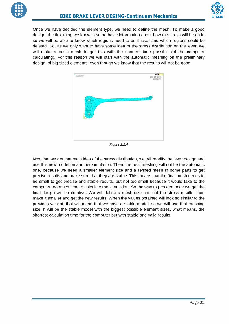
Once we have decided the element type, we need to define the mesh. To make a good
design, the first thing we know is some basic information about how the stress will be on it,
so we will be able to know which regions need to be thicker and which regions could be
deleted. So, as we only want to have some idea of the stress distribution on the lever, we
will make a basic mesh to get this with the shortest time possible (of the computer
calculating). For this reason we will start with the automatic meshing on the preliminary
design, of big sized elements, even though we know that the results will not be good.
Figure 2.2.4
Now that we get that main idea of the stress distribution, we will modify the lever design and
use this new model on another simulation. Then, the best meshing will not be the automatic
one, because we need a smaller element size and a refined mesh in some parts to get
precise results and make sure that they are stable. This means that the final mesh needs to
be small to get precise and stable results, but not too small because it would take to the
computer too much time to calculate the simulation. So the way to proceed once we get the
final design will be iterative: We will define a mesh size and get the stress results; then
make it smaller and get the new results. When the values obtained will look so similar to the
previous we got, that will mean that we have a stable model, so we will use that meshing
size. It will be the stable model with the biggest possible element sizes, what means, the
shortest calculation time for the computer but with stable and valid results.
BIKE BRAKE LEVER DESING-Continuum Mechanics
Page 23
2.3. Results reliability: refined meshing
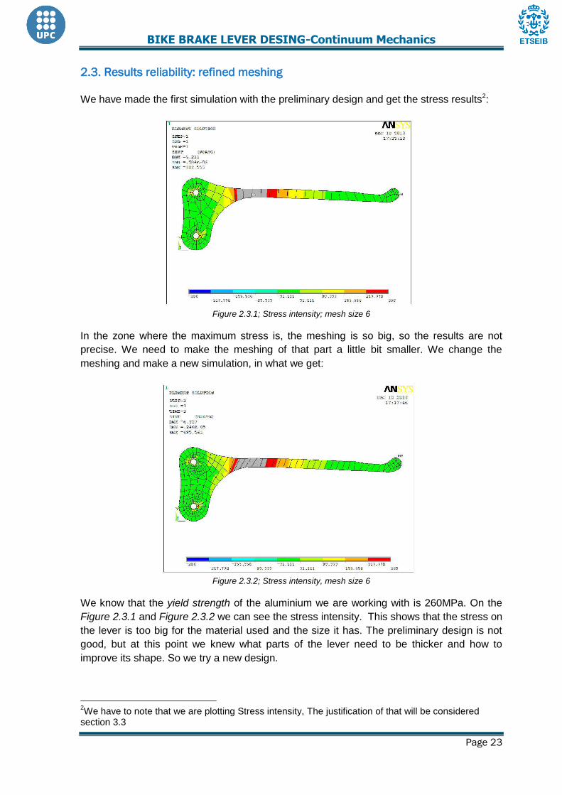
We have made the first simulation with the preliminary design and get the stress results2:
Figure 2.3.1; Stress intensity; mesh size 6
In the zone where the maximum stress is, the meshing is so big, so the results are not
precise. We need to make the meshing of that part a little bit smaller. We change the
meshing and make a new simulation, in what we get:
Figure 2.3.2; Stress intensity, mesh size 6
We know that the yield strength of the aluminium we are working with is 260MPa. On the
Figure 2.3.1 and Figure 2.3.2 we can see the stress intensity. This shows that the stress on
the lever is too big for the material used and the size it has. The preliminary design is not
good, but at this point we knew what parts of the lever need to be thicker and how to
improve its shape. So we try a new design.
2We have to note that we are plotting Stress intensity, The justification of that will be considered
section 3.3

BIKE BRAKE LEVER DESING-Continuum Mechanics
Page 24
Figure 2.3.3
The improvements we make for this new design are:
We move the part where the pressure is applied closer to the cotter pins to reduce
the resultant moment.
We make the width bigger where the stress is maximal.
We make thinner the part close to the cotter pins where the stress is small to make
it lighter.
We cut off the right part because it is not useful and this way we can reduce the
weight too.
So with the new design we make the new model and the simulation with the same
boundary conditions. And the results of the stress are:
Figure 2.3.4: Stress Intensity, Nominal Force
Now is time to stabilize the results. We will observe just one node and we will see if the
stress intensity remains constant until some element size. We will try that the node will be
always the same but in fact it is impossible. However we can chose to nodes close enough
to get us an idea of meshing stability.
We chose the node with coordinates x=60,6158mm and y= 31,9633mm.

BIKE BRAKE LEVER DESING-Continuum Mechanics
Page 25
Element size Sint (MPa) Figure
7 157,573
6 155,63
5 151,17
4 153,847
3 153,76
As we can see at size 4 the mesh is stable. In fact, we have 0,05% variation in Sint
between element sizes 3 and 4.So we will take the element size 4 as the optimal meshing
model.

BIKE BRAKE LEVER DESING-Continuum Mechanics
Page 26
We can see that there is a singular point as we expected for the hypothesis made before.
Figure 2.3.5
After observing the results, we can see that the singularities created are not close to the
zone where we know that stress intensity is higher, so they do not affect this part.
It looks like the new design would be able to bear the maximal force that someone could do
on it with one hand. So the next step is to make the failing simulation. We were using
Fnom= 392kg for the maximum force. For this new simulation we need the load to be
between 1,2Fnom and 1,3Fnom and the stress on the lever should be higher than the yield
stress, so it has to deform plastically. We proceed and simulate the same model changing
the pressure value3.
3 We will see this modelling at section 3

BIKE BRAKE LEVER DESING-Continuum Mechanics
Page 27
2.4. Infinitesimal displacement hypothesis, nonlinear calculation
In order to proof that linear approximation is correct we must start a nonlinear calculation to
determine it (Figure 4.4.1. and Figure 2.4.2).
Figure 2.4.1; Newton Raphson convergence
Figure 2.4.2; Left side (nonlinear deformation)-Right side (linear deformation)
After this study we can appreciate that the approximation made with the linear calculus is
correct as we have at the same point the same stress intensity for the both studies, with a
value of 153.81MPa (Figure 2.4.3.). Afterwards, we conclude that the approximation is quite
good to determine the stresses in our lever.
Figure 2.4.3; nonlinear stress intensity; Left side (nonlinear)-Right side (linear)

BIKE BRAKE LEVER DESING-Continuum Mechanics
Page 28
3. Results analysis
In this section we will show and analyse ANSYS results. We will present the displacements,
principal strength distribution and then we consider a failure criterion. This is a really
important section because we will know if the piece will resist or not. In next sections we will
optimize the design. But now we are going to analyse the results.
3.1. Current displacement
Before analysing the displacement and the deformed shape, we should know that the
hypothesis of linear approximation is based on little deformations, quite different from
considering little displacement. When considering the first one, we know that depends on
the previous length of the piece, like ε
, different from the second one. As we can see in
figure 3.1.2 the strain is quite small.
Then we test the lever with a pressure applied of 1,12MPa, corresponding to 1,2 of the
nominal pressure, to find the limit value for the brake lever to fail and improve the design.
The results obtained are in Figure 3.1.1, Figure 3.1.2 and Figure 3.1.3.
Figure 3.1.1 current displacement

BIKE BRAKE LEVER DESING-Continuum Mechanics
Page 29
Figure 3.1.2 deformed shape
Figure 3.1.3; Total strain
Ux Uy Uz
Displacement (mm) 0,32856 -2,3256 Unknown
ANSYS does not show up the real Uz displacement because it works only on one plane
and we are considering just a surface (taking into account the real thick to get the results).

BIKE BRAKE LEVER DESING-Continuum Mechanics
Page 30
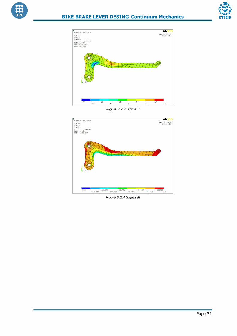
3.2. Principal strength distribution
Before analysing the results, we must know the distribution of stresses. That is, the upper
part in traction and the lower part in compression (Figure 3.2.1.). The lever is in a state of
plane stress for two reasons. First, we are not applying any force perpendicular to the
surface of the lever and then we are not considering the volume force created by the gravity
that is negligible compared with the force we are applying. However, this does not mean
that the second principal traction is always zero as there are nodes where the other
principal directions are either in traction or in compression. Moreover, in the nodes where
we have only compression, the z direction becomes the first principal direction, and where
we have traction it becomes the third. Obviously, when a node presents traction and
compression at once, that direction becomes the second principal (Figure 3.2.2, Figure
3.2.3 and Figure 3.2.4.).
Figure 3.2.1 Principal strength distribution
Figure 3.2.2 Sigma I
BIKE BRAKE LEVER DESING-Continuum Mechanics
Page 31
Figure 3.2.3 Sigma II
Figure 3.2.4 Sigma III

BIKE BRAKE LEVER DESING-Continuum Mechanics
Page 32
3.3. Failure criteria. Equivalent stress distribution
First of all we have to realize that we are dealing with aluminium. This means that we have
to a choose failure criteria that fit with it. Among the options we have, Tresca-Guest and
Von Mises (on Figure 3.3.1.), we have considered that Tresca-Guest is more suitable as it
is more restrictive. Then to study the results the equivalent stress will be stress intensity. If
the equivalent stress is higher in some node then the brake lever will plasticize.
Figure 3.3.1; Failure criteria (Tresca-Guest; Von Mises)
Figure 3.3.2; stress intensity distribution

BIKE BRAKE LEVER DESING-Continuum Mechanics
Page 33
The results are stable, but we want to ensure that they are valid. We want to make sure that
the boundary conditions represent the reality, but that the stress results do not depend too
much on them. So we are going to change the boundary conditions we had for another
hypothesis that can work too. We will fix the same upper point, with Ux=0, but now we will
impose on the lower pin, only rotation permitted (with symmetry ANSYS option). Then we
get that:
Figure 3.3.3; Symmetry boundary conditions
Figure 3.3.4.a; First boundary conditions Figure 3.3.4.b; Symmetry boundary conditions
Stress intensity when stabilizing Reaction solution
Initial boundary conditions 153.847 865.95
Changed boundary conditions 153.847 860.27
%variation 0 0,66
So we can conclude that the results do not depend on the way we impose some
restrictions, what makes it a robust valid model.

BIKE BRAKE LEVER DESING-Continuum Mechanics
Page 34
3.4. Security coefficient and load at failure
3.4.1 Security coefficient
Security coefficient is the relation between the maximum permissible stress, in our case,
the yield stress (260MPa) and the suitable equivalent stress (stress intensity). It is imposed
that this value must be between 1,2 and 1,3 , so in order to be accurate we try to get 1,25
knowing that it will be difficult to be exactly at this value.
The maximum stress intensity we obtain in nominal test is 172,73MPa (without taking into
account the numeric singularities). In this case we get that is far away from the
interval imposed. That result means that we must optimize our lever in order to reduce the
security coefficient, and try to get the entire lever working at the same stress intensity. This
aim is certainly impossible, but we have to attempt to, at least, that there is no part of the
piece that is not working.
Figure 3.4.1.1
3.4.2 Load at failure
One of the aims of that study is to get the maximum reaction force in the upper pin with the
minimum mass of the lever. So it is important to know the reaction at first and try to improve
it, making it higher and reducing all the mass that is not bearing any stress.
Analysing the lever in ANSYS when the material fails we obtain a reaction of Rf = 865,95 N.

BIKE BRAKE LEVER DESING-Continuum Mechanics
Page 35
4. Optimization of the design, construction, test and conclusions
At this point we find a model that fits our specifications unless the security coefficient. Now
is time to make it lighter. So in this section we will pass throw an iterative process. We will
start with this last model and we will begin to pick out mass and see if the piece is still
resisting. On this way we have to learn by assign and error the way to optimize the piece.
4.1 Optimization of the design and final results
4.1.1 Optimization process
In this section we will impose 1.2 times the nominal force in order to assure that the piece
does not break before we want. As we have seen before we have to consider stress
intensity.
We start with this design; stress is lower than the yield stress so we could pick out some
material to make it less resistant and at the same time that mass that does not bear any
stress.
Figure 4.1.1; tension intensity: first piece
Figure 4.1.1
First of all we remove some mass near to the holes and in the right part of the lever, where
there is a big zone that is not working at all. As we can see the piece is still resisting.

BIKE BRAKE LEVER DESING-Continuum Mechanics
Page 36
Figure 4.1.2; Stress intensity
We note that there is still some inner mass that is not working, as some in the right part of
the lever. So, we try to remove some mass realising that the lever fails.
Figure 4.1.3; Stress intensity
To solve this failure we decide to make a bridge to avoid it. We observe then that it is not
enough.

BIKE BRAKE LEVER DESING-Continuum Mechanics
Page 37
Figure 4.1.4; Stress intensity (zoom in left side)
With that last bridge we see that the failure has been solved. Thereupon, we try to reduce
mass in the right side, where there is a region where mass is not working at all.
Figure 4.1.5; Stress intensity

BIKE BRAKE LEVER DESING-Continuum Mechanics
Page 38
Finally, after having completely modified the first design we had, the final design is done.
The optimization process has allowed us to reduce considerably the mass of the lever and
to make some parts of the lever be working at higher stress intensity. It is quite obvious that
we could still going on the optimization process, but we consider our lever is enough
sophisticated.
Figure 4.1.6; Stress intensity

BIKE BRAKE LEVER DESING-Continuum Mechanics
Page 39
4.1.2 Refining mesh process
For that refining process we have fixed the point nearer from X=59,70mm Y=32,40mm.
Element size Sint (MPa) Figure
7 141,87
6 151,97
5 152,53
4 160,91
3 152,1

BIKE BRAKE LEVER DESING-Continuum Mechanics
Page 40
As we can see at size 5 the mesh is stable, in fact we have 0,28% variation between size 3
and 5. We notice at size 4 stress intensity is considerably higher than size 5, but this might
be for the simple reason that in each mesh we do not have exactly the same nodes, so the
coordinates used are a little bit different.
4.1.3 Current displacement
Figure 4.1.4.1; Displacement
Ux Uy Uz
Displacement (mm) 0,28 -2,99 0
4.1.4 Linear VS nonlinear calculus
We must analyze the final design with a nonlinear calculation in order to determine if is far
away or not from the linear one.
Figure 4.1.3.1 Newton Raphson Convergence

BIKE BRAKE LEVER DESING-Continuum Mechanics
Page 41
Figure 4.1.3.2; Left side (nonlinear)-Right side (linear)
Figure 4.1.3.2; Left side (nonlinear)-Right side (linear)
When we obtained the results we have chosen a point, of all we have looked for, as an
example of the little variation in stress intensity. The values are expressed in the next table.
Stress intensity when stabilizing (MPa)
Reaction Solution (N)
Linear calculus 152,54 1003,2
Nonlinear calculus 154,38 991,6
%variation 1,20 -1,17
After obtaining the results, we notice there are some differences between nonlinear and
linear calculus, as we expected, but these differences are very small. Thereupon, we
conclude we can still work with the linear hypothesis, unless we want to be more precise.

BIKE BRAKE LEVER DESING-Continuum Mechanics
Page 42
4.1.5 Principal stress directions
Analyzing again the principal stress directions we obtain similar results than the previous study. We have a zone in traction and zones in compression .We notice all the lever is working.
Figure 4.1.5.1; Sigma I,II,III
Figure 4.1.5.2; Sigma I

BIKE BRAKE LEVER DESING-Continuum Mechanics
Page 43
Figure 4.1.5.3; Sigma II
Figure 4.1.5.3; Sigma III
4.1.6 Security coefficient
At the final design we got a maximum stress intensity of 214,8MPa for the nominal force applied Fnom = 392N, obtaining . So, a value between the intervals imposed has been reached.
Figure 4.1.6.1; Stress intensity

BIKE BRAKE LEVER DESING-Continuum Mechanics
Page 44
4.1.7 Reaction force
As we have said before, when testing it will be difficult to get the exact value of 1,25 of the
nominal reaction, so we calculate the maximum and minimum force of the interval 1,2-1,3 in
order to enclose the reaction force between two limits. We only need to change the
pressure value (P = 0,93MPa) for the nominal multiplied for this interval coefficient and
analyse again the lever stress distribution and reaction.
So with the final design:
Using the right limit of the interval ( =1,3) and a pressure of 1,21
MPa we obtain a reaction force of 1086 N.
Using the left limit of the interval ( =1,2) and a pressure of 1,12
MPa we obtain a reaction force of 1005,2 N.
Figure 4.1.7
Without ANSYS we also can estimate the reaction, we just have to impose static and
compute total momentum. We obtain 1086,6 and 1005,7 N.
Now we have a brake lever that would be able to bear the maximum force that we can grip
strength with one hand. But there is another point we need to work on: We need to ensure
that this brake lever would make the bike stop when somebody pushes it with 6kg more or
less.
We start a new simulation with the final design and the same boundary conditions and finite
elements method characteristics and mesh, but changing the pressure value to
And the reaction force obtained in this case is R =124,15 N. We consider that this reaction force is enough to make the bike stop.
BIKE BRAKE LEVER DESING-Continuum Mechanics
Page 45
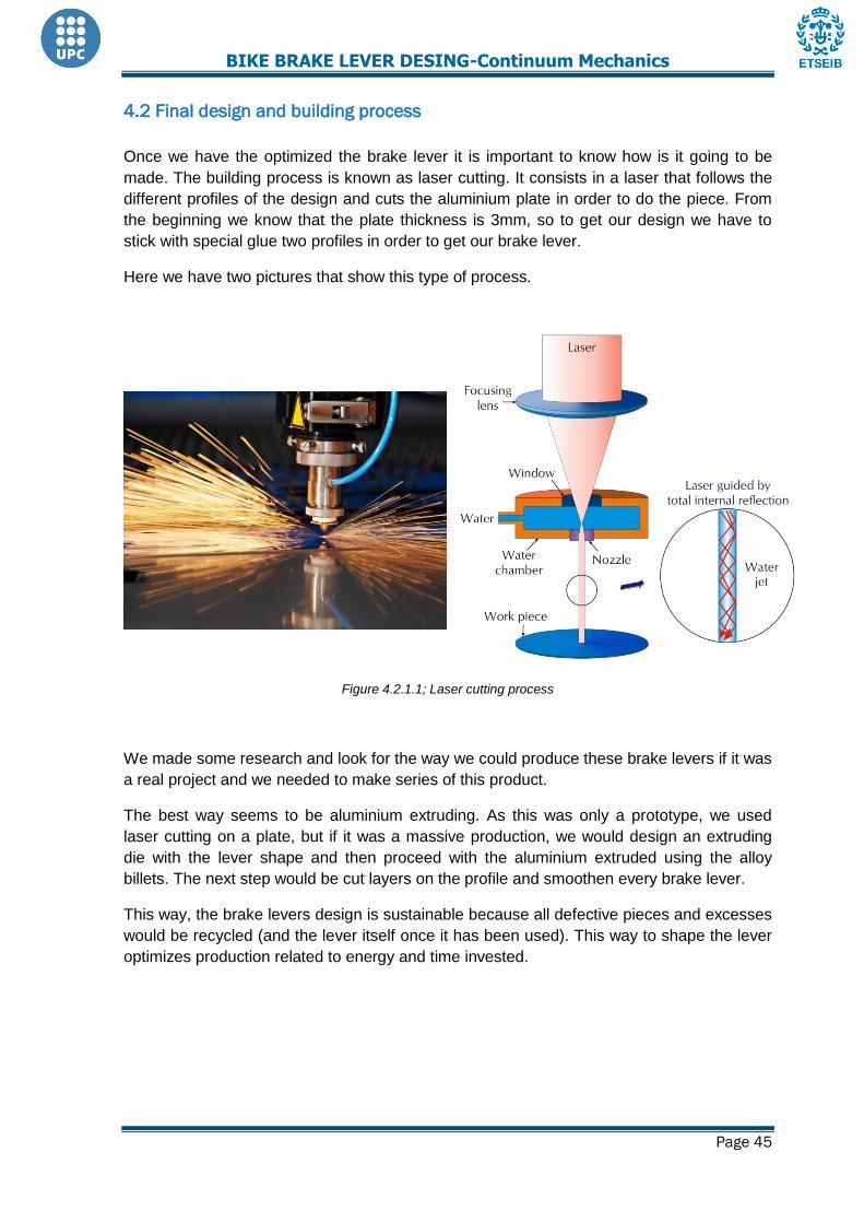
4.2 Final design and building process
Once we have the optimized the brake lever it is important to know how is it going to be
made. The building process is known as laser cutting. It consists in a laser that follows the
different profiles of the design and cuts the aluminium plate in order to do the piece. From
the beginning we know that the plate thickness is 3mm, so to get our design we have to
stick with special glue two profiles in order to get our brake lever.
Here we have two pictures that show this type of process.
Figure 4.2.1.1; Laser cutting process
We made some research and look for the way we could produce these brake levers if it was
a real project and we needed to make series of this product.
The best way seems to be aluminium extruding. As this was only a prototype, we used
laser cutting on a plate, but if it was a massive production, we would design an extruding
die with the lever shape and then proceed with the aluminium extruded using the alloy
billets. The next step would be cut layers on the profile and smoothen every brake lever.
This way, the brake levers design is sustainable because all defective pieces and excesses
would be recycled (and the lever itself once it has been used). This way to shape the lever
optimizes production related to energy and time invested.

BIKE BRAKE LEVER DESING-Continuum Mechanics
Page 46
BIKE BRAKE LEVER DESING-Continuum Mechanics
Page 47
4.3. Environmental impact and bill
The material we decided to use for this project is Aluminium. This decision was based on its
properties and characteristics that were important for our lever design. But moreover, the
aluminium has another important advantage: It is almost 100% recyclable. This fact is
making the use of aluminium grow because of the man trying to be less destructive for the
Earth. The opportunities of recycling the aluminium means it will not be left out somewhere
like a garbage dump damaging the environment. And it is important to highlight that
aluminium recycling is quite easy and obtaining aluminium form used aluminium only
requires a 5% of the total energy needed to get it from the bauxite mineral. This makes
aluminium producers be interested in dealing with aluminium pieces that are not useful
anymore to recycle them.
Therefore, our brake lever is recyclable, what makes it viable and sustainable, and it is
positive now that this characteristic is considered as a very important one.
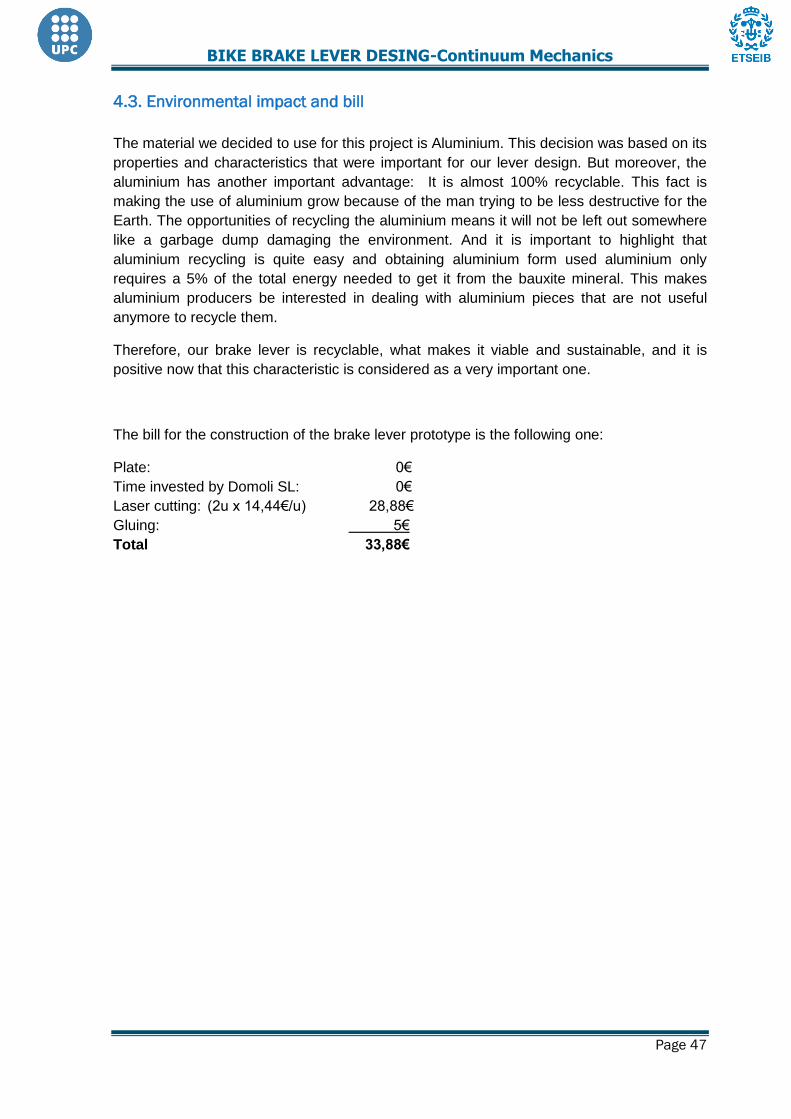
The bill for the construction of the brake lever prototype is the following one:
Plate: 0€
Time invested by Domoli SL: 0€
Laser cutting: (2u x 14,44€/u) 28,88€
Gluing: 5€
Total 33,88€

BIKE BRAKE LEVER DESING-Continuum Mechanics
Page 48
5. Test and conclusions

BIKE BRAKE LEVER DESING-Continuum Mechanics
Page 49
6. References
[1] G.E. Mase & G.T. Mase “Stress principles” in Continuum mechanics for engineers, CRC
Press, London, 1992
[2]X. Ayneto & M. Ferrer.Mecánica del medio continuo en la ingeniería. Teoría y problemas
resueltos. Iniciativa Digital Politècnica. Col·lecció Grau UPC – Enginyeries Industrials.
Barcelona, 2013.
[3] Spanish legislation (UNE-EN 14764): http://www.viesverdes.cat/pdf/documentacio4.pdf
[4] Shimano: Componentes de bicicletas (2013). Manual de soporte de ventas.
[5] Performance Composites Ltd (FC properties): http://www.performance-composites.com/carbonfibre/mechanicalproperties_2.asp [6] Mechanical Engineering online guide (FC properties): http://www.mechanicalengineeringblog.com/tag/carbon-fibre-properties [7] Composite resources (FC properties): http://composite-resources.com/composites/composite-properties/ [8] MatWeb, Material property data (Aluminium properties):
http://www.crptechnology.com/sito/images/PDF/6082.pdf
[9] Aalco, UK’s multi-metals stockholder (Aluminium properties):
http://www.aalco.co.uk/datasheets/Aluminium-Alloy_6082-T4_147.ashx
[10] European steel and alloy grades (Aluminium properties):
http://www.steelnumber.com/en/steel_alloy_composition_eu.php?name_id=1157
[11] El prisma, apuntes de ingeniería civil (Boxwood properties):
http://www.elprisma.com/apuntes/ingenieria_civil/madera/default2.asp
[12] The Wood database (Boxwood properties):
http://www.wood-database.com/lumber-identification/hardwoods/boxwood/
[13] Steinwall (Methacrylate properties):http://www.steinwall.com/ART-PMMA.html
[14] University of Auckland. Mechanical properties of glassy poly (Methacrylate properties):
https://researchspace.auckland.ac.nz/handle/2292/2527
[15] Plásticos FerPlaST (Methacrylate properties):
http://www.plasticosferplast.com/files/producto/pmma.pdf
[16] Domoli S.L. Especialistes en transformació metàl·lica.
Carrer del Vallespir, 7. 17800 Olot, Girona.
[17] Tecalum Industrial SL
Crta de Sales, 2. 17853 Tortellà, Girona.