
BIG-IP® Local Traffic Manager™: Implementations result.....31 3 Table of Contents Creating IP...
212
BIG-IP ® Local Traffic Manager ™ : Implementations Version 11.2.1
Transcript of BIG-IP® Local Traffic Manager™: Implementations result.....31 3 Table of Contents Creating IP...

BIG-IP® Local Traffic Manager™:Implementations
Version 11.2.1


Table of Contents
Configuring a Simple Intranet..................................................................................................13
Overview: A simple intranet configuration........................................................................13
Task summary..................................................................................................................13
Creating a pool......................................................................................................14
Creating a virtual server........................................................................................14
Configuring ISP Load Balancing.............................................................................................15
Overview: ISP load balancing..........................................................................................15
Illustration of ISP load balancing...........................................................................15
Task summary for ISP load balancing..............................................................................15
Creating a load balancing pool..............................................................................15
Creating a virtual server for inbound content server traffic...................................16
Creating a virtual server for outbound traffic for routers........................................17
Creating self IP addresses for an external VLAN..................................................17
Enabling SNAT automap for internal and external VLANs....................................17
Routing Based on XML Content..............................................................................................19
Overview: XML content-based routing.............................................................................19
Task summary..................................................................................................................19
Creating a custom XML profile..............................................................................20
Writing XPath queries............................................................................................21
Creating a pool to manage HTTP traffic................................................................21
Creating an iRule...................................................................................................22
Viewing statistics about XML content-based routing.............................................24
Configuring an EtherIP Tunnel................................................................................................25
Overview: Preserving BIG-IP connections during live virtual machine migration............25
Illustration of EtherIP tunneling in a vMotion environment....................................25
Task summary..................................................................................................................26
Creating a VLAN...................................................................................................26
Creating an EtherIP profile....................................................................................27
Creating an EtherIP tunnel object.........................................................................27
Creating a VLAN group.........................................................................................28
Creating self IP addresses for VLANs...................................................................28
Creating a self IP for a VLAN group......................................................................29
Creating a Virtual Location monitor.......................................................................30
Syncing the BIG-IP configuration to the device group...........................................30
Implementation result.......................................................................................................31
3
Table of Contents

Creating IP Tunnels..................................................................................................................33
About IP tunnels...............................................................................................................33
About point-to-point tunnels.............................................................................................33
Creating a point-to-point IP tunnel.........................................................................34
About tunnels between the BIG-IP system and other devices.........................................34
Creating an encapsulation tunnel between a BIG-IP device and multiple
devices.............................................................................................................35
Configuring nPath Routing......................................................................................................37
Overview: Layer 2 nPath routing......................................................................................37
About Layer 2 nPath routing configuration.......................................................................38
Guidelines for UDP timeouts............................................................................................38
Guidelines for TCP timeouts............................................................................................38
Task summary..................................................................................................................39
Creating a custom Fast L4 profile.........................................................................39
Creating a server pool for nPath routing................................................................39
Creating a virtual server for Layer 2 nPath routing................................................40
Configuring the virtual address on the server loopback interface.........................40
Setting the route for inbound traffic.......................................................................40
Configuring the Connection.Autolasthop bigdb key...............................................41
Configuring Layer 3 nPath Routing.........................................................................................43
Overview: Layer 3 nPath routing......................................................................................43
Configuring Layer 3 nPath routing using tmsh.................................................................43
Configuring a Layer 3 nPath monitor using tmsh.............................................................44
Layer 3 nPath routing example.........................................................................................45
Creating a Basic Web Site and E-commerce Configuration.................................................47
Overview: Basic web site and eCommerce configuration................................................47
Illustration of basic web site and eCommerce configuration.................................47
Task summary..................................................................................................................47
Creating a pool to manage HTTP traffic................................................................48
Creating a pool to manage HTTPS traffic.............................................................48
Creating a virtual server to manage HTTP traffic..................................................49
Creating a virtual server to manage HTTPS traffic...............................................50
Installing a BIG-IP System Without Changing the IP Network.............................................51
Overview: Installing a BIG-IP system without changing the IP network...........................51
Task summary..................................................................................................................52
Removing the self IP addresses from the default VLANs.....................................52
Creating a VLAN group.........................................................................................52
Creating a self IP for a VLAN group......................................................................53
4
Table of Contents
Creating a pool of web servers..............................................................................53
Creating a virtual server........................................................................................53
Web Hosting Multiple Customers Using an External Switch................................................55
Overview: Web hosting multiple customers using an external switch..............................55
Illustration for hosting multiple customers using an external switch.................................55
Task summary for hosting multiple customers.................................................................55
Creating a VLAN with a tagged interface..............................................................56
Creating a load balancing pool..............................................................................56
Creating a virtual server for HTTP traffic...............................................................57
Web Hosting Multiple Customers Using Untagged Interfaces.............................................59
Overview: Web hosting multiple customers using untagged interfaces...........................59
Illustration for hosting multiple customers using untagged interfaces...................59
Task summary for hosting multiple customers.................................................................59
Creating a VLAN with an untagged interface........................................................60
Creating a load balancing pool..............................................................................60
Creating a virtual server for HTTP traffic...............................................................61
Web Hosting Multiple Customers Using Route Domains.....................................................63
Overview: Use of route domains to host multiple web customers on the BIG-IP
system.........................................................................................................................63
Illustration of sample BIG-IP configuration using route domains...........................64
Illustration of resulting route domain configuration................................................64
Task summary..................................................................................................................65
Creating an administrative partition.......................................................................65
Creating a VLAN with a tagged interface..............................................................66
Creating a self IP address for a default route domain in an administrative
partition............................................................................................................66
Creating a route domain on a BIG-IP LTM system................................................67
Creating a load balancing pool..............................................................................68
Creating a virtual server........................................................................................68
Configuring route advertisement for a virtual address..........................................69
Adding routes that specify VLAN internal as the resource....................................69
Enabling IP Address Intelligence............................................................................................71
Overview: Enabling IP address intelligence.....................................................................71
Enabling IP address intelligence...........................................................................71
Creating an iRule to log IP address intelligence information.................................72
Creating an iRule to reject requests with questionable IP addresses...................73
Checking the reputation of an IP address.............................................................73
Checking the status of the IP intelligence database..............................................74
IP address intelligence categories...................................................................................74
5
Table of Contents

Managing Client-side HTTPS Traffic Using a Self-signed Certificate..................................77
Overview: Managing client-side HTTPS traffic using a self-signed certificate.................77
Task summary..................................................................................................................77
Creating a self-signed SSL certificate...................................................................77
Creating a custom HTTP service profile...............................................................78
Creating a custom Client SSL profile....................................................................78
Creating a pool to manage HTTP traffic................................................................79
Creating a virtual server for client-side HTTPS traffic...........................................79
Implementation result.......................................................................................................80
Managing Client and Server HTTPS Traffic using a Self-signed Certificate.......................81
Overview: Managing client and server HTTPS traffic using a self-signed certificate.......81
Task summary..................................................................................................................81
Creating a self-signed SSL certificate...................................................................81
Creating a custom HTTP service profile...............................................................82
Creating a custom Client SSL profile....................................................................82
Creating a custom Server SSL profile...................................................................83
Creating a pool to manage HTTPS traffic.............................................................83
Creating a virtual server for client-side and server-side HTTPS traffic.................84
Implementation results.....................................................................................................85
Managing Client-side HTTPS Traffic using a CA-signed Certificate....................................87
Overview: Managing client-side HTTPS traffic using a CA-signed certificate..................87
Task summary..................................................................................................................87
Requesting a certificate from a certificate authority..............................................87
Creating a custom HTTP service profile...............................................................88
Creating a custom Client SSL profile....................................................................88
Creating a pool to manage HTTP traffic................................................................89
Creating a virtual server for client-side HTTPS traffic...........................................89
Implementation results.....................................................................................................90
Implementing Proxy SSL on a Single BIG-IP System............................................................91
Overview: Direct client-server authentication with application optimization.....................91
Task summary..................................................................................................................91
Creating a custom Client SSL profile....................................................................92
Creating a custom Server SSL profile...................................................................92
Creating a load balancing pool..............................................................................93
Creating a virtual server for client-side and server-side SSL traffic......................93
Implementation result.......................................................................................................94
Configuring HTTP Load Balancing with Source Address Affinity Persistence..................95
Overview: HTTP load balancing with source affinity persistence.....................................95
6
Table of Contents

Task summary..................................................................................................................95
Creating a pool to manage HTTP traffic................................................................95
Creating a virtual server for HTTP traffic...............................................................96
Configuring HTTP Load Balancing with Cookie Persistence...............................................97
Overview: HTTP load balancing with cookie persistence................................................97
Task summary..................................................................................................................97
Creating a custom cookie persistence profile........................................................97
Creating a pool to manage HTTP traffic................................................................98
Creating a virtual server for HTTP traffic...............................................................98
Compressing HTTP Responses............................................................................................101
Overview: Compressing HTTP responses.....................................................................101
Task summary................................................................................................................101
Creating a customized HTTP compression profile..............................................101
Creating a virtual server for HTTP compression.................................................102
Using the Request Logging Profile.......................................................................................103
Overview: Configuring a request logging profile............................................................103
Task summary................................................................................................................103
Creating a pool with request logging to manage HTTP traffic.............................103
Creating a request logging profile.......................................................................104
Configuring a virtual server for request logging..................................................106
Deleting a request logging profile........................................................................106
Request logging profile settings.....................................................................................106
Request logging parameters..........................................................................................108
Load Balancing Passive Mode FTP Traffic...........................................................................111
Overview: FTP passive mode load balancing................................................................111
Task Summary for load balancing passive mode FTP traffic.........................................111
Creating a custom FTP monitor..........................................................................111
Creating a pool to manage FTP traffic................................................................113
Creating a virtual server for FTP traffic...............................................................114
Load Balancing Passive Mode FTP Traffic with Data Channel Optimization....................115
Overview: FTP passive mode load balancing with data channel optimization...............115
Task Summary for load balancing passive mode FTP traffic.........................................115
Creating a custom FTP profile.............................................................................115
Creating a custom FTP monitor..........................................................................116
Creating a pool to manage FTP traffic................................................................117
Creating a virtual server for FTP traffic...............................................................118
Implementation result.....................................................................................................119
7
Table of Contents

Referencing an External File from within an iRule..............................................................121
Overview: Referencing an external file from an iRule....................................................121
iRule commands for iFiles...................................................................................121
Task summary................................................................................................................122
Importing a file to the BIG-IP system..................................................................122
Creating an iFile..................................................................................................122
Writing an iRule that references an iFile.............................................................123
Implementation result.....................................................................................................123
Configuring the BIG-IP System as a DHCP Relay Agent....................................................125
Overview: Managing IP addresses for DHCP clients.....................................................125
About the BIG-IP system as a DHCP relay agent...............................................125
Task summary................................................................................................................126
Creating a pool of DHCP servers........................................................................126
Creating a DHCP Relay type virtual server.........................................................127
Implementation result.....................................................................................................127
Configuring the BIG-IP System for DHCP Renewal.............................................................129
Overview: Renewing IP addresses for DHCP clients.....................................................129
About DHCP renewal .........................................................................................129
Task summary................................................................................................................129
Creating a DHCP renewal virtual server.............................................................130
Implementation result.....................................................................................................130
Configuring a One-IP Network Topology..............................................................................131
Overview: Configuring a one-IP network topology.........................................................131
Illustration of a one-IP network topology for the BIG-IP system..........................131
Task summary for a one-IP network topology for the BIG-IP system.............................132
Creating a pool for processing HTTP connections with SNATs enabled.............132
Creating a virtual server for HTTP traffic.............................................................132
Defining a default route.......................................................................................133
Configuring a client SNAT...................................................................................133
Implementing Health and Performance Monitoring.............................................................135
Overview: Health and performance monitoring..............................................................135
Task summary................................................................................................................135
Creating a custom monitor..................................................................................136
Creating a load balancing pool............................................................................136
Creating a virtual server......................................................................................137
Preventing TCP Connection Requests From Being Dropped.............................................139
Overview: TCP request queuing....................................................................................139
8
Table of Contents

Preventing TCP connection requests from being dropped.............................................139
Setting Connection Limits.....................................................................................................141
Overview: About connection limits.................................................................................141
Limiting connections for a virtual server, pool member, or node....................................141
Implementation results...................................................................................................141
Load Balancing to IPv6 Nodes..............................................................................................143
Overview: Load balancing to iPv6 nodes.......................................................................143
Task summary................................................................................................................143
Configuring the radvd service (optional).............................................................143
Creating a load balancing pool............................................................................144
Creating a virtual server for IPv6 nodes..............................................................144
Configuring DNS Express......................................................................................................147
How do I configure DNS Express?.................................................................................147
What is DNS Express?........................................................................................147
Task summary................................................................................................................147
Configuring a back-end DNS server to allow zone file transfers.........................147
Creating a DNS Express TSIG key.....................................................................148
Creating a DNS Express zone............................................................................148
Enabling DNS Express .......................................................................................149
Assigning a DNS profile to a virtual server..........................................................150
Assigning a DNS profile to a listener...................................................................150
Viewing information about DNS Express zones..................................................150
Implementation result.....................................................................................................151
Configuring Fast DNS.............................................................................................................153
Overview: Improving DNS performance by caching responses from external
resolvers....................................................................................................................153
Task summary................................................................................................................154
Creating a transparent DNS cache.....................................................................154
Creating a custom DNS profile for transparent DNS caching.............................154
Assigning a custom DNS profile to an LTM virtual server...................................155
Assigning a custom DNS profile to a GTM listener.............................................155
Creating a custom DNS monitor..........................................................................155
Creating a pool of local DNS servers..................................................................156
Determining DNS cache performance................................................................156
Clearing a DNS cache.........................................................................................158
Implementation result.....................................................................................................158
Resolving DNS Queries and Caching Responses...............................................................159
9
Table of Contents
Overview: Improving DNS performance by resolving queries and caching
responses.................................................................................................................159
Task summary................................................................................................................160
Creating a resolver DNS cache...........................................................................160
Creating a custom DNS profile for DNS resolving and caching..........................160
Assigning a custom DNS profile to an LTM virtual server...................................161
Assigning a custom DNS profile to a GTM listener.............................................161
Determining DNS cache performance................................................................161
Clearing a DNS cache.........................................................................................163
Implementation result.....................................................................................................164
Resolving DNS Queries and Caching Validated Responses..............................................165
Overview: Resolving queries and caching validated responses....................................165
Task summary................................................................................................................166
Creating a validating resolver DNS cache...........................................................167
Creating a custom DNS profile for validating resolver DNS caching...................168
Assigning a custom DNS profile to an LTM virtual server...................................168
Assigning a custom DNS profile to a GTM listener.............................................169
Determining DNS cache performance................................................................169
Clearing a DNS cache.........................................................................................171
Implementation result.....................................................................................................171
Customizing a DNS Cache.....................................................................................................173
Overview: Customizing a DNS cache............................................................................173
Configuring a DNS cache to answer queries for local zones.........................................173
Configuring a DNS cache to use specific root nameservers..........................................173
Configuring a DNS cache alert for cache poisoning......................................................174
Load Balancing DNS Traffic Between IPv-6 Only and IPv-4 Only Clouds.........................175
Overview: Handling IPv6-only connection requests to IPv4-only servers......................175
Task summary................................................................................................................175
Creating a custom DNS profile ...........................................................................175
Assigning a DNS profile to a virtual server..........................................................177
Implementation result.....................................................................................................177
Mitigating Denial of Service Attacks.....................................................................................179
Overview: Mitigating Denial of Service and other attacks..............................................179
Denial of Service attacks and iRules.............................................................................179
iRules for Code Red attacks................................................................................179
iRules for Nimda attacks.....................................................................................180
Common Denial of Service attacks................................................................................180
Task summary................................................................................................................182
Configuring adaptive reaping..............................................................................183
10
Table of Contents

Setting the TCP and UDP connection timers......................................................183
Applying a rate class to a virtual server..............................................................183
Calculating connection limits on the main virtual server.....................................184
Setting connection limits on the main virtual server............................................184
Adjusting the SYN Check threshold....................................................................184
Configuring Remote CRLDP Authentication........................................................................185
Overview of remote authentication for application traffic................................................185
Task Summary...............................................................................................................185
Creating a CRLDP configuration object for authenticating application traffic
remotely.........................................................................................................185
Creating a custom CRLDP profile.......................................................................186
Modifying a virtual server for CRLDP authentication..........................................186
Configuring Remote SSL LDAP Authentication...................................................................189
Overview of remote SSL LDAP authentication for application traffic.............................189
Task Summary...............................................................................................................189
Creating an LDAP Client Certificate SSL configuration object............................189
Creating a custom SSL Client Certificate LDAP profile.......................................190
Modifying a virtual server for SSL Client Certificate LDAP authorization............190
Configuring Remote SSL OCSP Authentication..................................................................193
Overview of remote authentication for application traffic................................................193
Task Summary...............................................................................................................193
Creating an SSL OSCP responder object for authenticating application traffic
remotely.........................................................................................................193
Creating an SSL OCSP configuration object for authenticating application traffic
remotely.........................................................................................................194
Creating a custom SSL OCSP profile.................................................................194
Modifying a virtual server for SSL OCSP authentication.....................................195
Load Balancing Diameter Application Requests.................................................................197
Overview: Diameter load balancing...............................................................................197
Task summary................................................................................................................197
Creating a custom Diameter profile.....................................................................197
Creating a custom Diameter monitor...................................................................197
Creating a pool to manage Diameter traffic.........................................................198
Creating a virtual server to manage Diameter traffic...........................................198
Legal Notices..........................................................................................................................201
Legal Notices.................................................................................................................201
Acknowledgments..........................................................................................................202
11
Table of Contents

12
Table of Contents
Configuring a Simple Intranet
Overview: A simple intranet configuration
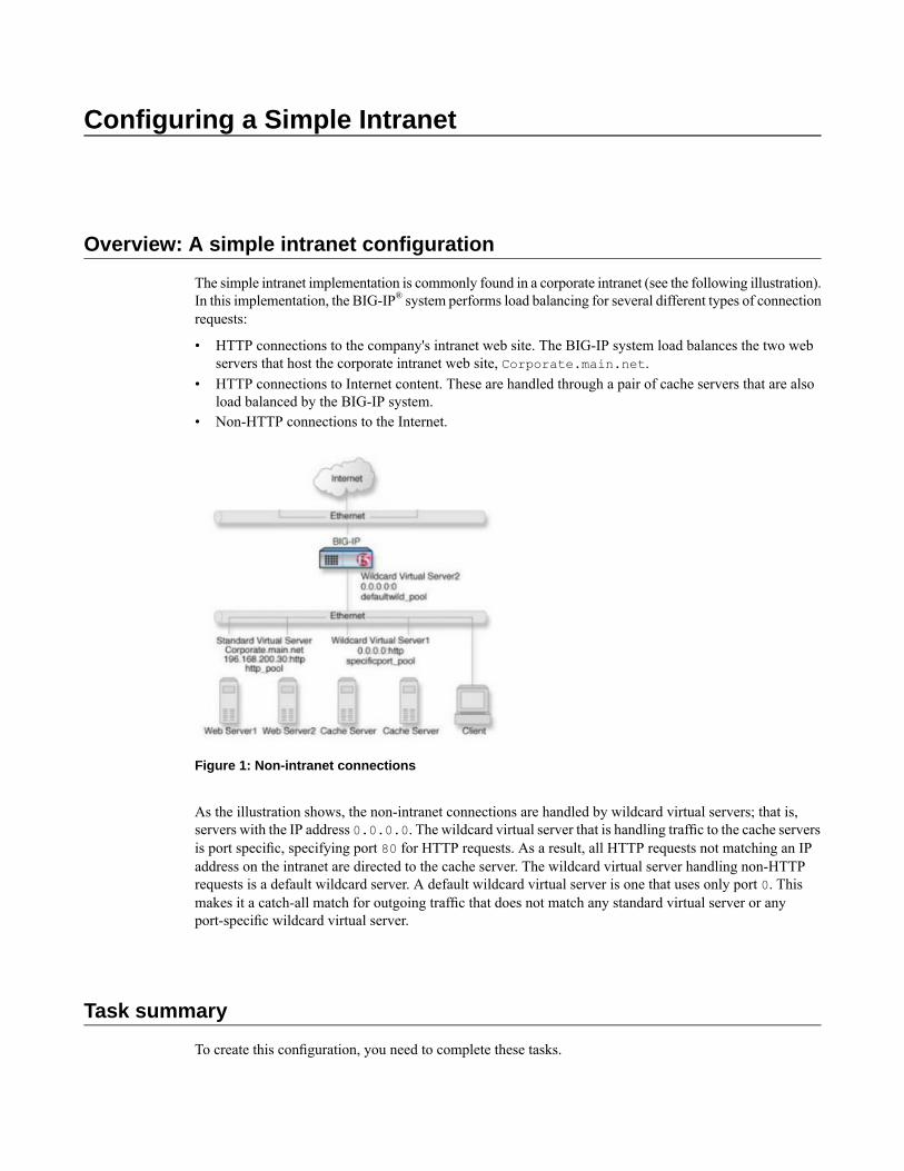
The simple intranet implementation is commonly found in a corporate intranet (see the following illustration).In this implementation, the BIG-IP® system performs load balancing for several different types of connectionrequests:
• HTTP connections to the company's intranet web site. The BIG-IP system load balances the two webservers that host the corporate intranet web site, Corporate.main.net.
• HTTP connections to Internet content. These are handled through a pair of cache servers that are alsoload balanced by the BIG-IP system.
• Non-HTTP connections to the Internet.
Figure 1: Non-intranet connections
As the illustration shows, the non-intranet connections are handled by wildcard virtual servers; that is,servers with the IP address 0.0.0.0. The wildcard virtual server that is handling traffic to the cache serversis port specific, specifying port 80 for HTTP requests. As a result, all HTTP requests not matching an IPaddress on the intranet are directed to the cache server. The wildcard virtual server handling non-HTTPrequests is a default wildcard server. A default wildcard virtual server is one that uses only port 0. Thismakes it a catch-all match for outgoing traffic that does not match any standard virtual server or anyport-specific wildcard virtual server.
Task summary
To create this configuration, you need to complete these tasks.

Task listCreating a poolCreating a virtual server
Creating a pool
You can a create pool of servers that you group together to receive and process traffic, to efficiently distributethe load on your server resources.
1. On the Main tab, click Local Traffic > Pools.The Pool List screen opens.
2. Click Create.The New Pool screen opens.
3. In the Name field, type a unique name for the pool.4. In the Resources area of the screen, use theNewMembers setting to add the pool members. For example,
in the illustration, the pool members for http_pool are 192.168.100.10:80 and 192.168.100.11:80.The pool members for specificport_pool are 192.168.100.20:80 and 192.168.100.21:80.
5. Click Finished.
The load balancing pool appears in the Pools list.
Creating a virtual server
This task creates a destination IP address for application traffic. As part of this task, you must assign therelevant pool to the virtual server.
1. On the Main tab, click Local Traffic > Virtual Servers.The Virtual Server List screen displays a list of existing virtual servers.
2. Click the Create button.The New Virtual Server screen opens.
3. In the Name field, type a unique name for the virtual server.4. In the Destination field, verify that the type of virtual server is Host, and in the Address field, type an
IP address for the virtual server.For example, you can assign the IP address 192.168.200.30:80 to the virtual server that processesHTTP traffic. For load balancing connections to cache servers, you can assign the address 0.0.0.0:80to the virtual server, making it a wildcard virtual server. To create a forwarding virtual server, you canassign the address 0.0.0.0:0.
5. In the Service Port field, type 80, or select HTTP from the list.6. In the Configuration area of the screen, locate theType setting and select either Standard or Forwarding
(IP).7. From the HTTP Profile list, select an HTTP profile.8. In the Resources area of the screen, from the Default Pool list, select a pool name.9. Click Finished.
You now have a virtual server to use as a destination address for application traffic.
14
Configuring a Simple Intranet

Configuring ISP Load Balancing
Overview: ISP load balancing
Youmight find that as your network grows, or network traffic increases, you require an additional connectionto the Internet. You can use this configuration to add an Internet connection to your existing network. Thefollowing illustration shows a network configured with two Internet connections.
Illustration of ISP load balancing
Task summary for ISP load balancing
There are number of tasks you must perform to implement load balancing for ISPs.
Task listCreating a load balancing poolCreating a virtual server for inbound content server trafficCreating a virtual server for outbound traffic for routersCreating self IP addresses for an external VLANEnabling SNAT automap for internal and external VLANs
Creating a load balancing pool
You can a create load balancing pool, which is a logical set of devices, such as web servers, that you grouptogether to receive and process traffic, to efficiently distribute the load on your resources. Using thisprocedure, create one pool that load balances the content servers, and one pool to load balance the routers.

1. On the Main tab, click Local Traffic > Pools.The Pool List screen opens.
2. Click Create.The New Pool screen opens.
3. In the Name field, type a unique name for the pool.4. For the Health Monitors setting, in the Available list, select a monitor type, and click << to move the
monitor to the Active list.
Tip: Hold the Shift or Ctrl key to select more than one monitor at a time.
5. From the Load Balancing Method list, select how the system distributes traffic to members of thispool.The default is Round Robin.
6. For the Priority Group Activation setting, specify how to handle priority groups:
• Select Disabled to disable priority groups. This is the default option.• Select Less than, and in the Available Members field, type the minimum number of members that
must remain available in each priority group in order for traffic to remain confined to that group.
7. Using the New Members setting, add each resource that you want to include in the pool:a) Either type an IP address in the Address field, or select a node address from the Node List.b) Type a port number in the Service Port field, or select a service name from the list.c) To specify a priority group, type a priority number in the Priority field.d) Click Add.
8. Click Repeat and create another pool.9. Click Finished.
The load balancing pools appear in the Pools list.
Creating a virtual server for inbound content server traffic
You must create a virtual server to load balance inbound connections. The default pool that you assign asa resource in this procedure is the pool of internal servers.
1. On the Main tab, click Local Traffic > Virtual Servers.The Virtual Server List screen displays a list of existing virtual servers.
2. Click the Create button.The New Virtual Server screen opens.
3. In the Name field, type a unique name for the virtual server.4. For the Destination setting, in the Address field, type the IP address you want to use for the virtual
server.The IP address you type must be available and not in the loopback network.
5. For the Service Port setting, type a port number in the field, or select a service name from the list.6. If the traffic to be load balanced is of a certain type, select the profile type that matches the connection
type.To load balance HTTP traffic, locate the HTTP Profile setting and select http.
7. In the Resources area of the screen, from the Default Pool list, select a pool name.8. Click Finished.
16
Configuring ISP Load Balancing
The virtual server is configured to load balance inbound connections to the servers.
Creating a virtual server for outbound traffic for routers
You must create a virtual server to load balance outbound connections. The default pool that you assign asa resource in this procedure is the pool of routers.
1. On the Main tab, click Local Traffic > Virtual Servers.The Virtual Server List screen displays a list of existing virtual servers.
2. Click the Create button.The New Virtual Server screen opens.
3. In the Name field, type a unique name for the virtual server.4. For the Destination setting, in the Address field, type the IP address you want to use for the virtual
server.The IP address you type must be available and not in the loopback network.
5. In the Resources area of the screen, from the Default Pool list, select a pool name.6. Click Finished.
The virtual server is configured to load balance outbound connections to the routers.
Creating self IP addresses for an external VLAN
You must assign two self IP addresses to the external VLAN.
1. On the Main tab, click Network > Self IPs.The Self IPs screen opens.
2. Click Create.The New Self IP screen opens.
3. In the IP Address field, type an IP address.This IP address should represent the network of the router.The system accepts IP addresses in both the IPv4 and IPv6 formats.
4. In the Netmask field, type the network mask for the specified IP address.5. Select External from the VLAN list.6. Click Repeat.7. In the IP Address field, type an IP address.
This IP address should represent the address space of the VLAN that you specify with theVLAN/Tunnelsetting.The system accepts IP addresses in both the IPv4 and IPv6 formats.
8. Click Finished.The screen refreshes, and displays the new self IP address in the list.
The self IP address is assigned to the external VLAN.
Enabling SNAT automap for internal and external VLANs
You can configure SNAT automapping on the BIG-IP system for internal and external VLANs.
17
BIG-IP® Local Traffic Manager™: Implementations

1. On the Main tab, click Local Traffic > SNATs.The SNAT List screen displays a list of existing SNATs.
2. Click Create.3. Name the new SNAT.4. From the Translation list, select automap.5. For the VLAN List setting, in the Available field, select external and external, and using theMove
button, move the VLANs to the Selected field.6. Click Finished.
SNAT automapping on the BIG-IP system is configured for internal and external VLANs.
18
Configuring ISP Load Balancing

Routing Based on XML Content
Overview: XML content-based routing
You can use the BIG-IP® system to performXML content-based routing whereby the system routes requeststo an appropriate pool, pool member, or virtual server based on specific content in an XML document. Forexample, if your company transfers information in XML format, you could use this feature to examine theXML content with the intent to route the information to the appropriate department.
You configure content-based routing by creating an XML profile and associating it with a virtual server.In the XML profile, define the matching content to look for in the XML document. Next, specify how toroute the traffic to a pool by writing simple iRules®. When the system discovers a match, it triggers an iRuleevent, and then you can configure the system to route traffic to a virtual server, a pool, or a node. You canallow multiple query matches, if needed.
This example shows a simple XML document that the system could use to perform content-based routing.It includes an element called FinanceObject used in this implementation.
<soapenv:Envelope xmlns:xsi="http://www.w3.org/2001/XMLSchema-instance"xmlns:xsd="http://www.w3.org/2001/XMLSchema"xmlns:soapenv="http://schemas.xmlsoap.org/soap/envelope/"xmlns:eai="http://192.168.149.250/eai_enu/"xmlns:soapenc="http://schemas.xmlsoap.org/soap/encoding/">
<soapenv:Header/><soapenv:Body><eai:SiebelEmployeeDelete
soapenv:encodingStyle="http://schemas.xmlsoap.org/soap/encoding/"><FinanceObject xsi:type="xsd:string">Route to
Financing</FinanceObject><SiebelMessage xsi:type="ns:ListOfEmployeeInterfaceTopElmt"
xmlns:ns="http://www.siebel.com/xml"><ListOfEmployeeInterface
xsi:type="ns:ListOfEmployeeInterface"><SecretKey>123456789</SecretKey>
<Employee>John</Employee><Title>CEO</Title>
</ListOfEmployeeInterface></SiebelMessage>
</eai:SiebelEmployeeDelete></soapenv:Body>
</soapenv:Envelope>
Task summary
You can perform tasks to enable XML content-based routing whereby the system routes requests to anappropriate pool, pool member, or virtual server based on specific content in an XML document.
Task listCreating a custom XML profile

Writing XPath queriesCreating a pool to manage HTTP trafficCreating an iRuleViewing statistics about XML content-based routing
Creating a custom XML profile
To implement content-based routing, you first need to create an XML profile. XML profiles specify thecontent to look for in XML documents. In the XML profile, you define XPath queries to locate items in anXML document.
1. On the Main tab, click Local Traffic > Profiles > Services > XML.The XML screen opens.
2. Click Create.The New XML screen opens.
3. In the Name field, type a unique name for the XML profile, such as cbr_xml_profile.4. In the Settings area, select the Custom check box at right.
The settings become available.5. If you want to reference XML elements with namespaces in XPath queries, fromNamespaceMappings,
select Specify.The screen displays the Namespace Mappings List settings.
6. Add namespaces to the list to specify how to map XML namespaces (as defined by the xmlns attribute)for the system to use when routing XML traffic to the correct pool, pool member, or virtual server:a) In the Prefix field, type the namespace prefix.b) In the Namespace field, type the URL that the prefix maps to.c) Click Add to add the namespace to the Namespace Mappings List.
7. To define the matching criteria in the XML document, from XPath Queries, select Specify.The screen displays the XPath Queries settings.
8. Add XPath queries to the list to define matching criteria in XML payloads so the system can route thetraffic to the correct pool, pool member, or virtual server:a) In the XPath field, type an XPath expression.
For example, to look for an element called FinanceObject, type //FinanceObject.b) Click Add to add the XPath expression to the XPath Queries list.
You can define up to three XPath queries.The expression is added to the list.
9. To allow each query to have multiple matches, selectMultiple Query Matches.10. Click Finished.
The system creates an XML profile.
You can use the XML profile to route XML traffic. Note that XML profiles do not support use of the Expectheader field. This is because the header of a transaction could direct it to one pool, and the payload couldinvoke an iRule to direct the transaction to a different pool.
20
Routing Based on XML Content
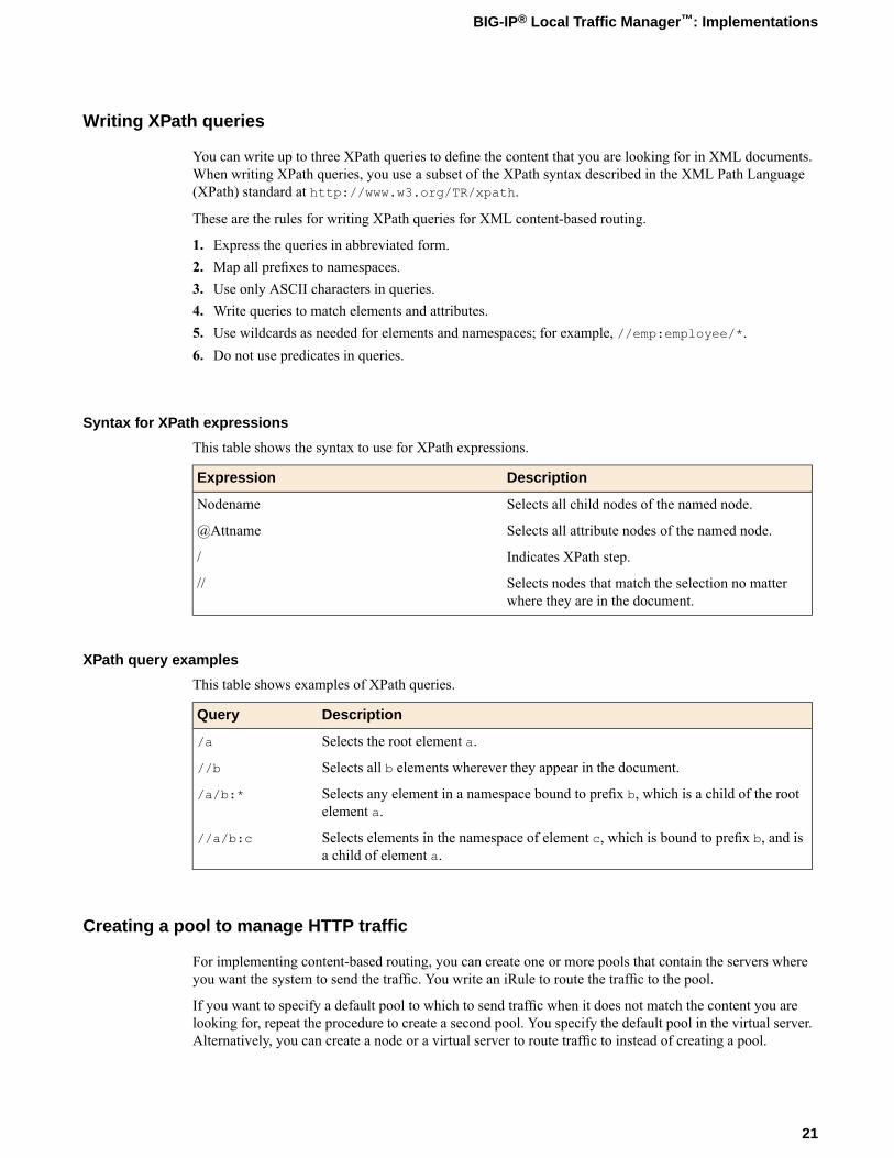
Writing XPath queries
You can write up to three XPath queries to define the content that you are looking for in XML documents.When writing XPath queries, you use a subset of the XPath syntax described in the XML Path Language(XPath) standard at http://www.w3.org/TR/xpath.
These are the rules for writing XPath queries for XML content-based routing.
1. Express the queries in abbreviated form.2. Map all prefixes to namespaces.3. Use only ASCII characters in queries.4. Write queries to match elements and attributes.5. Use wildcards as needed for elements and namespaces; for example, //emp:employee/*.6. Do not use predicates in queries.
Syntax for XPath expressions
This table shows the syntax to use for XPath expressions.
DescriptionExpression
Selects all child nodes of the named node.Nodename
Selects all attribute nodes of the named node.@Attname
Indicates XPath step./
Selects nodes that match the selection no matterwhere they are in the document.
//
XPath query examples
This table shows examples of XPath queries.
DescriptionQuery
Selects the root element a./a
Selects all b elements wherever they appear in the document.//b
Selects any element in a namespace bound to prefix b, which is a child of the rootelement a.
/a/b:*
Selects elements in the namespace of element c, which is bound to prefix b, and isa child of element a.
//a/b:c
Creating a pool to manage HTTP traffic
For implementing content-based routing, you can create one or more pools that contain the servers whereyou want the system to send the traffic. You write an iRule to route the traffic to the pool.
If you want to specify a default pool to which to send traffic when it does not match the content you arelooking for, repeat the procedure to create a second pool. You specify the default pool in the virtual server.Alternatively, you can create a node or a virtual server to route traffic to instead of creating a pool.
21
BIG-IP® Local Traffic Manager™: Implementations

1. On the Main tab, click Local Traffic > Pools.The Pool List screen opens.
2. Click Create.The New Pool screen opens.
3. In the Name field, type a name for the pool, such as finance_pool.4. For theHealth Monitors setting, from the Available list, select the httpmonitor, and click << to move
the monitor to the Active list.5. From the Load Balancing Method list, select how the system distributes traffic to members of this
pool.The default is Round Robin.
6. For the Priority Group Activation setting, specify how to handle priority groups:
• Select Disabled to disable priority groups. This is the default option.• Select Less than, and in the Available Members field, type the minimum number of members that
must remain available in each priority group in order for traffic to remain confined to that group.
7. Using the New Members setting, add each resource that you want to include in the pool:a) Type an IP address in the Address field, or select a node address from the Node List.b) Type 80 in the Service Port field, or select HTTP from the list.c) (Optional) Type a priority number in the Priority field.d) Click Add.
8. Click Finished.
The new pool appears in the Pools list.
Creating an iRule
You create iRules® to automate traffic forwarding for XML content-based routing. When a match occurs,an iRule event is triggered, and the iRule directs the individual request to a pool, a node, or virtual server.This implementation targets a pool.
1. On the Main tab, click Local Traffic > iRules.
2. Click Create.3. In the Name field, type a 1- to 31-character name, such as XML_CBR_iRule.4. In the Definition field, type the syntax for the iRule using Tool Command Language (Tcl) syntax.
For complete and detailed information iRules syntax, see the F5 Networks DevCentral web sitehttp://devcentral.f5.com.
5. Click Finished.
Examples of iRules for XML content-based routing
This example shows an iRule that queries for an element called FinanceObject in XML content and if amatch is found, an iRule event is triggered. The system populates the values of the Tcl variables
22
Routing Based on XML Content
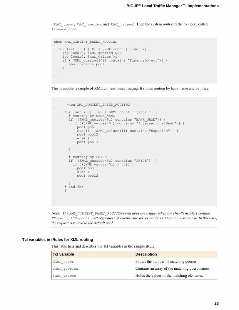
($XML_count, $XML_queries, and $XML_values). Then the system routes traffic to a pool calledfinance_pool.
when XML_CONTENT_BASED_ROUTING{for {set i 0} { $i < $XML_count } {incr i} {log local0. $XML_queries($i)log local0. $XML_values($i)if {($XML_queries($i) contains "FinanceObject")} {
pool finance_pool}
}}
This is another example of XML content-based routing. It shows routing by bank name and by price.
when XML_CONTENT_BASED_ROUTING{
for {set i 0} { $i < $XML_count } {incr i} {# routing by BANK_NAMEif {($XML_queries($i) contains "BANK_NAME")} {if {($XML_values($i) contains "InternationalBank")} {pool pool1
} elseif {($XML_values($i) contains "Hapoalim")} {pool pool2
} else {pool pool3
}}
# routing by PRICEif {($XML_queries($i) contains "PRICE")} {if {($XML_values($i) > 50)} {pool pool1
} else {pool pool2
}}
# end for}
}
Note: The XML_CONTENT_BASED_ROUTING event does not trigger when the client's headers contain"Expect: 100-continue" regardless of whether the server sends a 100-continue response. In this case,the request is routed to the default pool.
Tcl variables in iRules for XML routing
This table lists and describes the Tcl variables in the sample iRule.
DescriptionTcl variable
Shows the number of matching queries.$XML_count
Contains an array of the matching query names.$XML_queries
Holds the values of the matching elements.$XML_values
23
BIG-IP® Local Traffic Manager™: Implementations

Viewing statistics about XML content-based routing
You can view statistics about XML content-based routing to make sure that the routing is working.
Note: The system first checks for a match, then checks for malformedness of XML content. So if the systemdetects a match, it stops checking, and might not detect any subsequent parts of the document that aremalformed.
1. On the Main tab, click Statistics >Module Statistics > Local Traffic.The Local Traffic Statistics screen opens.
2. From the Statistics Type list, select Profiles Summary.3. In the Global Profile Statistics area, for the Profile Type XML, click View in the Details.
The system displays information about the number of XML documents that were inspected, the numberof documents that had zero to three matches, and the number of XML documents that were found to bemalformed.
24
Routing Based on XML Content
Configuring an EtherIP Tunnel
Overview: Preserving BIG-IP connections during live virtual machinemigration
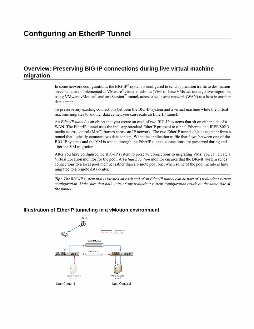
In some network configurations, the BIG-IP® system is configured to send application traffic to destinationservers that are implemented as VMware® virtual machines (VMs). These VMs can undergo live migration,using VMware vMotion™ and an iSession™ tunnel, across a wide area network (WAN) to a host in anotherdata center.
To preserve any existing connections between the BIG-IP system and a virtual machine while the virtualmachine migrates to another data center, you can create an EtherIP tunnel.
An EtherIP tunnel is an object that you create on each of two BIG-IP systems that sit on either side of aWAN. The EtherIP tunnel uses the industry-standard EtherIP protocol to tunnel Ethernet and IEEE 802.3media access control (MAC) frames across an IP network. The two EtherIP tunnel objects together form atunnel that logically connects two data centers. When the application traffic that flows between one of theBIG-IP systems and the VM is routed through the EtherIP tunnel, connections are preserved during andafter the VM migration.
After you have configured the BIG-IP system to preserve connections to migrating VMs, you can create aVirtual Location monitor for the pool. A Virtual Location monitor ensures that the BIG-IP system sendsconnections to a local pool member rather than a remote pool one, when some of the pool members havemigrated to a remote data center.
Tip: The BIG-IP system that is located on each end of an EtherIP tunnel can be part of a redundant systemconfiguration. Make sure that both units of any redundant system configuration reside on the same side ofthe tunnel.
Illustration of EtherIP tunneling in a vMotion environment

Task summary
Implement an EtherIP tunneling configuration to prevent the BIG-IP® system from dropping existingconnections to migrating virtual machines in a vMotion environment. To set up this configuration, you mustverify a few prerequisite tasks, as well as create some configuration objects on the BIG-IP system.
Important: Perform these tasks on the BIG-IP system in both the local data center and the remote datacenter.
Prerequisites
Before you begin configuring EtherIP tunneling, verify that these BIG-IP objects and module exist on theBIG-IP system:
An iSession profileThis profile creates an iSession tunnel to optimize the live migration of virtual machine servers fromone data center to another.
A load balancing poolThis pool represents a collection of virtual machines on a host server in the data center.
A standard TCP or UDP virtual serverThis virtual server load balances application traffic and optimizes vMotion traffic. This virtual servermust reference the iSession profile and the load balancing pool.
The default VLANsThese VLANs are named external and internal.
BIG-IP Global Traffic Manager™
This module directs traffic to the correct BIG-IP® Local Traffic Manager™ virtual server.
Task listCreating a VLANCreating an EtherIP profileCreating an EtherIP tunnel objectCreating a VLAN groupCreating self IP addresses for VLANsCreating a self IP for a VLAN groupCreating a Virtual Location monitorSyncing the BIG-IP configuration to the device group
Creating a VLAN
VLANs represent a collection of hosts that can share network resources, regardless of their physical locationon the network.
1. On the Main tab, click Network > VLANs.The VLAN List screen opens.
2. Click Create.The New VLAN screen opens.
26
Configuring an EtherIP Tunnel

3. In the Name field, type a unique name for the VLAN.4. In the Tag field, type a numeric tag, from 1 to 4094, for the VLAN. Leave the field blank if you want
the BIG-IP system to automatically assign a VLAN tag.The VLAN tag identifies the traffic from hosts in the associated VLAN.
5. For the Interfaces setting, from the Available list, click an interface number or trunk name and add theselected interface or trunk to the Untagged list. Repeat this step as necessary.
6. From the Configuration list, select Advanced.7. Select the Source Check check box if you want the system to verify that the return route to an initial
packet is the same VLAN from which the packet originated.8. If you want to base redundant-system failover on VLAN-related events, select the Fail-safe box.9. In theMTU field, retain the default number of bytes (1500).10. Click Finished.
The screen refreshes, and displays the new VLAN in the list.
Creating an EtherIP profile
An EtherIP profile is a required component of an EtherIP tunnel in a vMotion™ environment. An EtherIPprofilemanages application traffic that traverses an EtherIP tunnel, for the purpose of preserving connectionswhen a virtual machine is migrating to another data center. You must perform this task using the TrafficManagement shell (tmsh), a command-line utility.
1. On the BIG-IP®system, start a console session.2. Type a user name and password, and press Enter.3. At the command prompt, type tmsh, and press Enter.
This opens the Traffic Management shell (tmsh).4. At the tmsh prompt, type net tunnel, and press Enter.5. Type create etherip etherip_profile_name, and press Enter.
This command creates an EtherIP profile, assigning all of the default values.6. Type save / sys config, and press Enter.7. To exit the Traffic Management shell (tmsh), type quit, and press Enter.
You now have an EtherIP profile that you can specify when you create an EtherIP tunnel object.
Creating an EtherIP tunnel object
Prerequisites: You must know the self IP address of the instance of the VLAN that exists, or will exist, onthe BIG-IP® system in the other data center.
The purpose of an EtherIP tunnel that contains an EtherIP type of profile is to enable the BIG-IP system topreserve any current connections to a server that is migrating to another data center by way of vMotion™.You must perform this task using the Traffic Management shell (tmsh), a command-line utility.
1. On the BIG-IP system, start a console session.2. Type a user name and password, and press Enter.3. At the command prompt, type tmsh and press Enter.
This opens the Traffic Management shell (tmsh).4. Type net tunnels, and press Enter.
27
BIG-IP® Local Traffic Manager™: Implementations

5. Type the following command, and then press Enter:Note that the self IP addresses that you specify are those that you create for the VLAN on both the localand the remote BIG-IP system.create tunnel tunnel_name profile etherip local-address local_self_ip_addressremote-address remote_self_ip_address
6. Type save / sys config, and press Enter.7. To exit the Traffic Management shell (tmsh), type quit, and press Enter.
The BIG-IP system configuration now includes a tunnel object.
Creating a VLAN group
VLAN groups consolidate Layer 2 traffic from two or more separate VLANs.
1. On the Main tab, click Network > VLANs > VLAN Groups.The VLAN Groups list screen opens.
2. Click Create.The New VLAN Group screen opens.
3. In the General Properties area, in the VLAN Group field, type a unique name for the VLAN group.4. For the VLANs setting, move the VLANs that you want to include in the group from the Available list
to theMembers list.5. From the Transparency Mode list, select a transparency mode, or retain the default setting,
Transparent.The transparency mode determines the level of exposure of remote MAC addresses within the VLANgroup traffic.
PurposeModeThe MAC addresses of remote systems are exposed in Layer 2 trafficforwarding.
Transparent
Similar to Transparent mode, except the locally-unique bit is set in theMAC addresses of remote systems.
Translucent
The system uses proxyARPwith Layer 3 forwarding, so theMAC addressesof remote systems are not exposed.
Opaque
6. Select the Bridge All Traffic check box if you want the VLAN group to forward all frames, includingnon-IP traffic.The default setting is disabled (not selected).
7. Leave the Bridge in Standby check box selected if you want the VLAN group to forward frames evenwhen the system is the standby unit of a redundant system.
8. Click Finished.
Creating self IP addresses for VLANs
You need at least one VLAN or VLAN group configured before you create a self IP address.
Self IP addresses enable the BIG-IP® system, and other devices on the network, to route application trafficthrough the associated VLAN or VLAN group. Repeat the steps in this task for each VLAN.
28
Configuring an EtherIP Tunnel

1. On the Main tab, click Network > Self IPs.The Self IPs screen opens.
2. Click Create.The New Self IP screen opens.
3. In the Name field, type a unique name that readily identifies the VLAN to which it will associate forthe self IP.Name the self IP for the internal VLAN Internal, name the external VLAN External, and name theHA VLAN HA.
4. In the IP Address field, type an IP address.This IP address must be within the address space that corresponds to the VLAN for which it is created(Internal, External or HA).The system accepts IP addresses in both the IPv4 and IPv6 formats.
5. In the Netmask field, type the network mask for the specified IP address.6. From the VLAN/Tunnel list, select the VLAN to associate with this self IP address:
• For the internal network, select the VLAN that is associated with an internal interface or trunk.• For the external network, select the VLAN that is associated with an external interface or trunk.• For the HA network, select the VLAN that is associated with an internal interface or trunk.
7. From the Port Lockdown list, select Allow Default.8. Repeat the last 4 steps, but this time specify an address from your external network in step 4 and select
the VLAN named external in step 6.9. Repeat steps 3 through 7 one more time, but this time specify an address on your internal network in
step 4 and select the VLAN named HA in step 6.10. Click Finished.
The screen refreshes, and displays the new self IP address in the list.
The BIG-IP system can send and receive traffic through the specified VLAN or VLAN group.
Creating a self IP for a VLAN group
You need at least one VLAN or VLAN group configured before you create a self IP address.
After you have created the VLAN group, create a self IP address for the VLAN group. The self IP addressfor the VLAN group provides a route for packets destined for the network. With the BIG-IP® system, thepath to an IP network is a VLAN. However, with the VLAN group feature used in this procedure, the pathto the IP network 10.0.0.0 is actually through more than one VLAN. As IP routers are designed to haveonly one physical route to a network, a routing conflict can occur. The self IP address feature on the BIG-IPsystem allows you to resolve the routing conflict by associating a self IP address with the VLAN group.
1. On the Main tab, click Network > Self IPs.The Self IPs screen opens.
2. Click Create.The New Self IP screen opens.
3. In the IP Address field, type an IP address.This IP address should represent the address space of the VLAN group that you specify with theVLAN/Tunnel setting.The system accepts IP addresses in both the IPv4 and IPv6 formats.
4. In the Netmask field, type the network mask for the specified IP address.5. From the VLAN/Tunnel list, select the VLAN group with which to associate this self IP address.
29
BIG-IP® Local Traffic Manager™: Implementations

6. From the Port Lockdown list, select Allow Default.7. Click Finished.
The screen refreshes, and displays the new self IP address in the list.
The BIG-IP system can send and receive traffic through the specified VLAN or VLAN group.
Creating a Virtual Location monitor
When the BIG-IP® system is directing application traffic to pool members that are implemented as virtualmachines, you should configure a Virtual Location type of monitor on the BIG-IP system. A Virtual Locationmonitor determines if a pool member is local to the data center or remote, and assigns a priority group tothe pool member accordingly. Themonitor assigns remote pool members a lower priority than local members,thus ensuring that the BIG-IP directs application requests to local pool members whenever possible.
1. On the Main tab, click Local Traffic >Monitors.The Monitor List screen opens.
2. Click Create.The New Monitor screen opens.
3. Type my_virtual_location_monitor in the Name field.4. From the Type list, select Virtual Location.5. From the Configuration list, select Advanced.6. Retain the default value (in seconds) of 5 in the Interval field.7. Retain the default value of Disabled in the Up Interval list.8. Retain the default value (in seconds) of 0 in the Time Until Up field.9. Retain the default value (in seconds) of 16 in the Timeout field.10. Type the name of the pool that you created prior to configuring EtherIP tunneling in the Pool Name
field.11. Click Finished.
After configuring the Virtual Location monitor, the BIG-IP system assigns each member of the designatedpool a priority group value to ensure that incoming connections are directed to a local pool member wheneverpossible.
F5 Networks recommends that you verify that BIG-IP®Global TrafficManager™ (GTM™) has automaticallyassigned a BIG-IP type of monitor to BIG-IP® Local Traffic Manager™ (LTM®). A BIG-IP type of monitorcan use the priority group assigned to each pool member to retrieve a gtm_score value.
Syncing the BIG-IP configuration to the device group
Before you sync the configuration, verify that the devices targeted for config sync are members of a devicegroup and that device trust has been established.
This task synchronizes the BIG-IP® configuration data from the local device to the devices in the devicegroup. This synchronization ensures that devices in the device group operate properly. When synchronizingself IP addresses, the BIG-IP system synchronizes floating self IP addresses only.
Important: You perform this task on either of the two devices, but not both.
1. On the Main tab, click Device Management > Overview.
30
Configuring an EtherIP Tunnel

2. In the Device Groups area of the screen, in the Name column, select the name of the relevant devicegroup.The screen expands to show a summary and details of the sync status of the selected device group, aswell as a list of the individual devices within the device group.
3. In the Devices area of the screen, in the Sync Status column, select the device that shows a sync statusof Changes Pending.
4. In the Sync Options area of the screen, select Sync Device to Group.5. Click Sync.
The BIG-IP system syncs the configuration data of the selected device in the Device area of the screento the other members of the device group.
Except for non-floating self IP addresses, the entire set of BIG-IP configuration data is replicated on eachdevice in the device group.Task summaryCreating a Virtual Location monitorTask summary
Implementation result
After you configure EtherIP tunneling on the BIG-IP system, you must perform the same configurationprocedure on the BIG-IP system in the remote data center to fully establish the EtherIP tunnel.
After the tunnel is established, the BIG-IP system preserves any open connections to migrating (or migrated)virtual machine servers.
31
BIG-IP® Local Traffic Manager™: Implementations


Creating IP Tunnels
About IP tunnels
Using F5® tunneling technologies, you can set up tunneling from devices on different Layer 2 networks, orscale multi-site data centers over Layer 3 pathways. When you know the IP address of the devices at bothends of the tunnel, you can create a point-to-point encapsulation tunnel between a BIG-IP® system andanother device. When multiple devices feed into a BIG-IP system, you can create a tunnel by specifyingonly the IP address on the BIG-IP device.
The BIG-IP system provides the following tunneling protocols, available using the browser-basedConfiguration utility or the Traffic Management shell (tmsh) command-line utility, and iControl®.
• EtherIP• GRE• IPIP
• IPv4IPv4• IPv4IPv6• IPv6IPv4• IPv6IPv6
• PPP• WCCPGRE
About point-to-point tunnels
Point-to-point IP encapsulation tunnels carry traffic through a routed network between known devices. Forexample, you can create a GRE tunnel to connect a BIG-IP® system to a remotely located pool member.
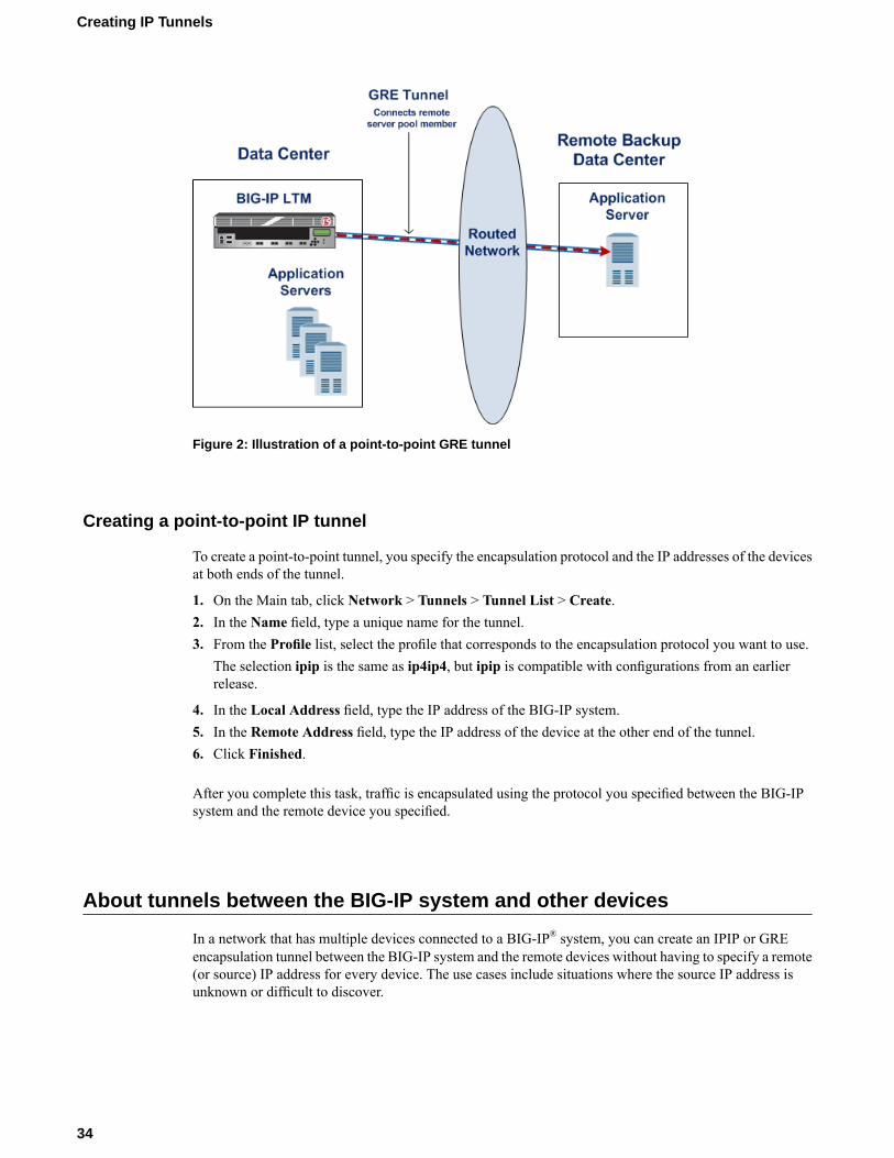
Figure 2: Illustration of a point-to-point GRE tunnel
Creating a point-to-point IP tunnel
To create a point-to-point tunnel, you specify the encapsulation protocol and the IP addresses of the devicesat both ends of the tunnel.
1. On the Main tab, click Network > Tunnels > Tunnel List > Create.2. In the Name field, type a unique name for the tunnel.3. From the Profile list, select the profile that corresponds to the encapsulation protocol you want to use.
The selection ipip is the same as ip4ip4, but ipip is compatible with configurations from an earlierrelease.
4. In the Local Address field, type the IP address of the BIG-IP system.5. In the Remote Address field, type the IP address of the device at the other end of the tunnel.6. Click Finished.
After you complete this task, traffic is encapsulated using the protocol you specified between the BIG-IPsystem and the remote device you specified.
About tunnels between the BIG-IP system and other devices
In a network that has multiple devices connected to a BIG-IP® system, you can create an IPIP or GREencapsulation tunnel between the BIG-IP system and the remote devices without having to specify a remote(or source) IP address for every device. The use cases include situations where the source IP address isunknown or difficult to discover.
34
Creating IP Tunnels

Figure 3: Illustration of an IPIP tunnel between a BIG-IP system and multiple unspecified devices
Creating an encapsulation tunnel between a BIG-IP device and multiple devices
You can create a tunnel between a BIG-IP® system and multiple remote devices without having to specifya remote (or source) IP address for every device.
1. On the Main tab, click Network > Tunnels > Tunnel List > Create.2. In the Name field, type a unique name for the tunnel.3. From the Profile list, select the profile that corresponds to the encapsulation protocol you want to use.
The selection ipip is the same as ip4ip4, but ipip is compatible with configurations from an earlierrelease.
4. In the Local Address field, type the IP address of the BIG-IP system.5. In the Remote Address field, type 0.0.0.0 or any.
This entry means that you do not have to specify the IP address of the remote end of the tunnel, whichallows multiple devices to use the same tunnel.
6. Click Finished.
When the BIG-IP system receives an encapsulated packet, the system decapsulates the packet, regardlessof the source address, and re-injects it into the IP stack, thus allowing the inner IP address to be associatedwith a virtual server.
35
BIG-IP® Local Traffic Manager™: Implementations


Configuring nPath Routing
Overview: Layer 2 nPath routing
With the Layer 2 nPath routing configuration, you can route outgoing server traffic around the BIG-IP®
system directly to an outbound router. This method of traffic management increases outbound throughputbecause packets do not need to be transmitted to the BIG-IP system for translation and then forwarded tothe next hop.
Figure 4: Layer 2 nPath routing
Note: The type of virtual server that processes the incoming traffic must be a transparent, non-translatingtype of virtual server.
In bypassing the BIG-IP system on the return path, Layer 2 nPath routing departs significantly from a typicalload-balancing configuration. In a typical load-balancing configuration, the destination address of theincoming packet is translated from that of the virtual server to that of the server being load balanced to,which then becomes the source address of the returning packet. A default route set to the BIG-IP systemthen sees to it that packets returning to the originating client return through the BIG-IP system, whichtranslates the source address back to that of the virtual server. The nPath configuration differs from thetypical load-balancing configuration, as illustrated in the following section.
Note: Do not attempt to use nPath routing for Layer 7 traffic. Certain traffic features do not work properlyif Layer 7 traffic bypasses the BIG-IP system on the return path.

About Layer 2 nPath routing configuration
The Layer 2 nPath routing configuration differs from the typical BIG-IP® load balancing configuration inthe following ways:
• The default route on the content servers must be set to the router's internal address (10.1.1.1 in theillustration) rather than to the BIG-IP system's floating self IP address (10.1.1.10). This causes the returnpacket to bypass the BIG-IP system.
• If you plan to use an nPath configuration for TCP traffic, you must create a Fast L4 profile with thefollowing custom settings:
• Enable the Loose Close setting. When you enable this setting, the TCP protocol flow expires morequickly, after a TCP FIN packet is seen. (A FIN packet indicates the tearing down of a previousconnection.)
• Set the TCP Close Timeout setting to the same value as the profile idle timeout if you expect halfcloses. If not, you can set this value to 5 seconds.
• Because address translation and port translation have been disabled, when the incoming packet arrivesat the pool member it is load balanced to the virtual server address (176.16.1.1 in the illustration), notto the address of the server. For the server to respond to that address, that address must be configuredon the loopback interface of the server and configured for use with the server software.
Guidelines for UDP timeouts
When you configure nPath for UDP traffic, the BIG-IP® system tracks packets sent between the same sourceand destination address to the same destination port as a connection. This is necessary to ensure the clientrequests that are part of a session always go to the same server. Therefore, a UDP connection is really aform of persistence, because UDP is a connectionless protocol.
To calculate the timeout for UDP, estimate the maximum amount of time that a server transmits UDP packetsbefore a packet is sent by the client. In some cases, the server might transmit hundreds of packets overseveral minutes before ending the session or waiting for a client response.
Guidelines for TCP timeouts
When you configure nPath for TCP traffic, the BIG-IP® system recognizes only the client side of theconnection. For example, in the TCP three-way handshake, the BIG-IP system sees the SYN from the clientto the server, and does not see the SYN acknowledgment from the server to the client, but does see theacknowledgment of the acknowledgment from the client to the server. The timeout for the connection shouldmatch the combined TCP retransmission timeout (RTO) of the client and the node as closely as possible toensure that all connections are successful.
The maximum initial RTO observed on most UNIX and Windows® systems is approximately 25 seconds.Therefore, a timeout of 51 seconds should adequately cover the worst case.When a TCP session is established,an adaptive timeout is used. In most cases, this results in a faster timeout on the client and node. Only inthe event that your clients are on slow, lossy networks would you ever require a higher TCP timeout forestablished connections.
38
Configuring nPath Routing

Task summary
There are several tasks you perform to create a Layer 2 nPath routing configuration.
Task listCreating a custom Fast L4 profileCreating a server pool for nPath routingCreating a virtual server for Layer 2 nPath routingConfiguring the virtual address on the server loopback interfaceSetting the route for inbound trafficConfiguring the Connection.Autolasthop bigdb key
Creating a custom Fast L4 profile
The first task you must complete to create a Layer 2 nPath routing configuration is to create a custom FastL4 profile.
1. On the Main tab, click Local Traffic > Profiles > Protocol > Fast L4.The Fast L4 screen opens.
2. Click Create.The New Fast L4 Profile screen opens.
3. In the Name field, type a name for the profile.4. Select the Custom check box.
The fields in the Settings area become available for revision.5. Select the Loose Close check box.6. Set the TCP Close Timeout setting, according to the type of traffic the virtual server is going to handle.7. Click Finished.
The custom Fast L4 profile appears in the list of Fast L4 profiles.
Creating a server pool for nPath routing
After you create a custom Fast L4 profile, you need to create a server pool.
1. On the Main tab, click Local Traffic > Pools.The Pool List screen opens.
2. Click Create.The New Pool screen opens.
3. In the Name field, type a unique name for the pool.4. For the Health Monitors setting, in the Available list, select a monitor type, and click << to move the
monitor to the Active list.
Tip: Hold the Shift or Ctrl key to select more than one monitor at a time.
5. Using the New Members setting, add each resource that you want to include in the pool:
39
BIG-IP® Local Traffic Manager™: Implementations

a) Either type an IP address in the Address field, or select a node address from the Node List.b) Type a port number in the Service Port field, or select a service name from the list.c) To specify a priority group, type a priority number in the Priority field.d) Click Add.
6. Click Finished.
Creating a virtual server for Layer 2 nPath routing
After you create a server pool, you need to create a virtual server that references the profile and pool youcreated.
1. On the Main tab, click Local Traffic > Virtual Servers.The Virtual Server List screen displays a list of existing virtual servers.
2. Click the Create button.The New Virtual Server screen opens.
3. In the Name field, type a unique name for the virtual server.4. For the Destination setting, in the Address field, type the IP address you want to use for the virtual
server.The IP address you type must be available and not in the loopback network.
5. From the Configuration list, select Advanced.6. From the Type list, select Performance (Layer 4).7. From the Protocol list, select one of the following:
• UDP• TCP• * All Protocols
8. From the Protocol Profile (Client) list, select a predefined or user-defined Fast L4 profile.9. Clear the Address Translation Enabled check box.10. Clear the Port Translation Enabled check box.11. In the Resources area, from the Default Pool list, select a user-defined pool.12. Click Finished.
Configuring the virtual address on the server loopback interface
You must place the IP address of the virtual server (176.16.1.1 in the illustration) on the loopback interfaceof each server. Most UNIX variants have a loopback interface named lo0. Consult your server operatingsystem documentation for information about configuring an IP address on the loopback interface. Theloopback interface is ideal for the nPath configuration because it does not participate in the ARP protocol.
Setting the route for inbound traffic
For inbound traffic, you must define a route through the BIG-IP® system self IP address to the virtual server.In the example, this route is 176.16.1.1, with the external self IP address 10.1.1.10 as the gateway.
40
Configuring nPath Routing

Note: You need to set this route only if the virtual server is on a different subnet than the router.
For information about how to define this route, please refer to the documentation provided with your router.
Configuring the Connection.Autolasthop bigdb key
To ensure that nPath routing works correctly, you must verify that the bigdb configuration keyconnection.autolasthop is set to enable. This is relevant for both IPv4 and IPv6 addressing formats. Toverify that this bigdb key is enabled, type this command at the tmsh prompt:modify sys db Connection.Autolasthop value enable
41
BIG-IP® Local Traffic Manager™: Implementations

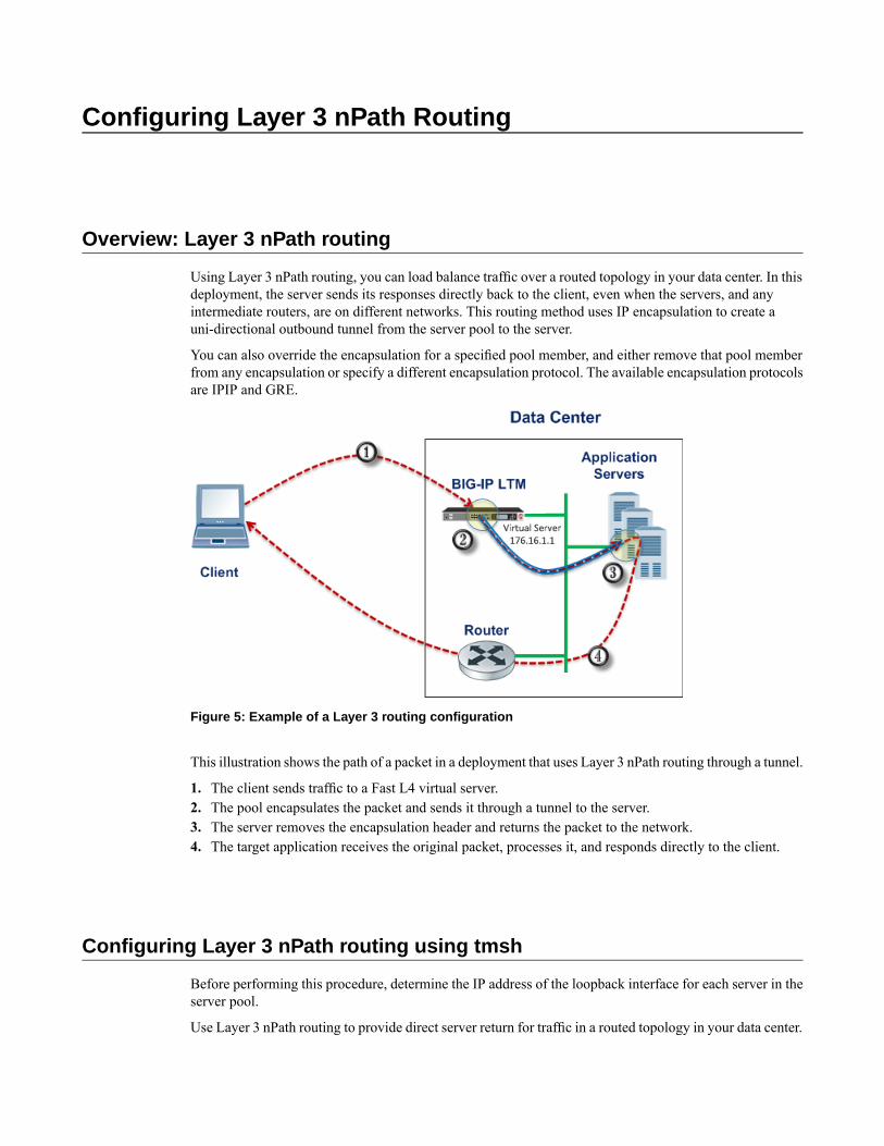
Configuring Layer 3 nPath Routing
Overview: Layer 3 nPath routing
Using Layer 3 nPath routing, you can load balance traffic over a routed topology in your data center. In thisdeployment, the server sends its responses directly back to the client, even when the servers, and anyintermediate routers, are on different networks. This routing method uses IP encapsulation to create auni-directional outbound tunnel from the server pool to the server.
You can also override the encapsulation for a specified pool member, and either remove that pool memberfrom any encapsulation or specify a different encapsulation protocol. The available encapsulation protocolsare IPIP and GRE.
Figure 5: Example of a Layer 3 routing configuration
This illustration shows the path of a packet in a deployment that uses Layer 3 nPath routing through a tunnel.
1. The client sends traffic to a Fast L4 virtual server.2. The pool encapsulates the packet and sends it through a tunnel to the server.3. The server removes the encapsulation header and returns the packet to the network.4. The target application receives the original packet, processes it, and responds directly to the client.
Configuring Layer 3 nPath routing using tmsh
Before performing this procedure, determine the IP address of the loopback interface for each server in theserver pool.
Use Layer 3 nPath routing to provide direct server return for traffic in a routed topology in your data center.

1. On the BIG-IP® system, start a console session.2. Create a server pool with an encapsulation profile.
tmsh create ltm pool npath_ipip_pool profiles add{ ipip } members add { 10.7.1.7:any 10.7.1.8:any 10.7.1.9:any }
This command creates the pool npath_ipip_pool, which has three members that specify all services:10.7.1.7:any, 10.7.1.8:any, and 10.7.1.9:any, and applies IPIP encapsulation to outboundtraffic.
3. Create a profile that disables hardware acceleration.
tmsh create ltm profile fastl4 fastl4_npath pva-acceleration none
This command disables the Packet Velocity®ASIC acceleration mode in the new Fast L4 profile namedfastl4_npath.
4. Create a virtual server that has address translation disabled, and includes the pool with the encapsulationprofile.
tmsh create ltm virtual npath_udp destination 176.16.1.1:anypool npath_ipip_pool profiles add { fastl4_npath } translate-addressdisabled ip-protocol udp
This command creates a virtual server named npath_udp that intercepts all UDP traffic, does not useaddress translation, and does not use hardware acceleration. The destination address 176.16.1.1matches the IP address of the loopback interface on each server.
These implementation steps configure only the BIG-IP device in a deployment example. To configure otherdevices in your network for L3 nPath routing, consult the device manufacturer's documentation for settingup direct server return (DSR) for each device.
Configuring a Layer 3 nPath monitor using tmsh
Before you begin this task, configure a server pool with an encapsulation profile, such as npath_ipip_pool.
You can create a custom monitor to provide server health checks of encapsulated tunnel traffic. Setting avariable in the db component causes the monitor traffic to be encapsulated.
1. Start at the Traffic Management Shell (tmsh).2. Create a transparent health monitor with the destination IP address of the virtual server that includes the
pool with the encapsulation profile.
tmsh create ltm monitor udp npath_udp_monitor transparent enabled destination176.16.1.1:*
This command creates a transparent monitor for UDP traffic with the destination IP address 176.16.1.1,and the port supplied by the pool member.
3. Associate the health monitor with the pool that has the encapsulation profile.
tmsh modify pool npath_ipip_pool monitor npath_udp_monitor
44
Configuring Layer 3 nPath Routing

This command specifies that the BIG-IP® system monitors UDP traffic to the pool npath_ipip_pool.4. Enable the variable in the db component that causes the monitor traffic to be encapsulated.
tmsh modify sys db tm.monitorencap value enable
This command specifies that the monitor traffic is encapsulated.
Layer 3 nPath routing example
The following illustration shows one example of an L3 nPath routing configuration in a network.
Figure 6: Example of a Layer 3 routing configuration
The following examples show the configuration code that supports the illustration.
Client configuration:
# ifconfig eth0 inet 10.102.45.10 netmask 255.255.255.0 up# route add –net 10.0.0.0 netmask 255.0.0.0 gw 10.102.45.1
BIG-IP® device configuration:
# - create node pointing to server's ethernet address# ltm node 10.102.4.10 {# address 10.102.4.10# }# - create transparent monitor# ltm monitor tcp t.ipip {# defaults-from tcp# destination 10.102.3.202:http# interval 5# time-until-up 0# timeout 16# transparent enabled# }# - create pool with ipip profile
45
BIG-IP® Local Traffic Manager™: Implementations

# ltm pool ipip.pool {# members {# 10.102.4.10:any { - real server's ip address# address 10.102.4.10# }# }# monitor t.ipip - transparent monitor# profiles {# ipip# }# }# - create FastL4 profile with PVA disabled# ltm profile fastl4 fastL4.ipip {# app-service none# pva-acceleration none# }# - create FastL4 virtual with custom FastL4 profile from previous step# ltm virtual test_virtual {# destination 10.102.3.202:any - server's loopback address# ip-protocol tcp# mask 255.255.255.255# pool ipip.pool - pool with ipip profile# profiles {# fastL4.ipip { } - custom fastL4 profile# }# translate-address disabled - translate address disabled# translate-port disabled# vlans-disabled# }
Linux DSR server configuration:
# modprobe ipip# ifconfig tunl0 10.102.4.10 netmask 255.255.255.0 up# ifconfig lo:0 10.102.3.202 netmask 255.255.255.255 -arp up# echo 1 > /proc/sys/net/ipv4/conf/all/arp_ignore# echo 2 > /proc/sys/net/ipv4/conf/all/arp_announce# echo 0 >/proc/sys/net/ipv4/conf/tunl0/rp_filter
46
Configuring Layer 3 nPath Routing

Creating a Basic Web Site and E-commerce Configuration
Overview: Basic web site and eCommerce configuration
The most common use for the BIG-IP® system is distributing traffic across an array of web servers that hoststandard web traffic, including eCommerce traffic. The following illustration shows a configuration wherea BIG-IP system load balances two sites: www.siterequest.com and store.siterequest.com. Thewww.siterequest.com site provides standard web content, and the store.siterequest.com site isthe e-commerce site that sells items to www.siterequest.com customers.
Illustration of basic web site and eCommerce configuration
Task summary
You can implement a basic configuration for load balancing application traffic to a web site, as well as loadbalancing secure traffic to an eCommerce site.
Prerequisites
• Verify that you have created two VLANs on the BIG-IP® system. One VLAN should reside on theexternal network and another on the internal network.
• Verify that you have created a self IP address for each VLAN.
Task listCreating a pool to manage HTTP trafficCreating a pool to manage HTTPS trafficCreating a virtual server to manage HTTP traffic

Creating a virtual server to manage HTTPS traffic
Creating a pool to manage HTTP traffic
You can create a pool to manage HTTP connections.
1. On the Main tab, click Local Traffic > Pools.The Pool List screen opens.
2. Click Create.The New Pool screen opens.
3. In the Name field, type a unique name for the pool.4. For theHealth Monitors setting, from the Available list, select the httpmonitor, and click << to move
the monitor to the Active list.5. From the Load Balancing Method list, select how the system distributes traffic to members of this
pool.The default is Round Robin.
6. For the Priority Group Activation setting, specify how to handle priority groups:
• Select Disabled to disable priority groups. This is the default option.• Select Less than, and in the Available Members field, type the minimum number of members that
must remain available in each priority group in order for traffic to remain confined to that group.
7. Using the New Members setting, add each resource that you want to include in the pool:a) Type an IP address in the Address field, or select a node address from the Node List.b) Type 80 in the Service Port field, or select HTTP from the list.c) (Optional) Type a priority number in the Priority field.d) Click Add.
8. Click Finished.
The new pool appears in the Pools list.
Creating a pool to manage HTTPS traffic
You can create a pool (a logical set of devices, such as web servers, that you group together to receive andprocess HTTPS traffic) to efficiently distribute the load on your server resources.
1. On the Main tab, click Local Traffic > Pools.The Pool List screen opens.
2. Click Create.The New Pool screen opens.
3. In the Name field, type a unique name for the pool.4. Assign the https or https_443 health monitor from the Available list by moving it to the Active list.5. From the Load Balancing Method list, select how the system distributes traffic to members of this
pool.The default is Round Robin.
6. For the Priority Group Activation setting, specify how to handle priority groups:
• Select Disabled to disable priority groups. This is the default option.
48
Creating a Basic Web Site and E-commerce Configuration

• Select Less than, and in the Available Members field, type the minimum number of members thatmust remain available in each priority group in order for traffic to remain confined to that group.
7. Add each resource that you want to include in the pool using the New Members setting:a) Type an IP address in the Address field, or select a node address from the Node List.b) Type 443 in the Service Port field, or select HTTPS from the list.c) (Optional) Type a priority number in the Priority field.d) Click Add.
8. Click Finished.
The HTTPS load balancing pool now appears in the Pool List screen.
Creating a virtual server to manage HTTP traffic
You can create a virtual server to manage HTTP traffic as either a host virtual server or a network virtualserver.
1. On the Main tab, click Local Traffic > Virtual Servers.The Virtual Server List screen displays a list of existing virtual servers.
2. Click the Create button.The New Virtual Server screen opens.
3. In the Name field, type a unique name for the virtual server.4. For the Destination setting, in the Address field, type the IP address you want to use for the virtual
server.The IP address you type must be available and not in the loopback network.
5. In the Service Port field, type 80, or select HTTP from the list.6. From the HTTP Profile list, select http.7. From the HTTP Compression Profile list, select one of the following profiles:
• httpcompression• wan-optimized-compression• A customized profile
8. (Optional) From theWeb Acceleration Profile list, select one of the following profiles:
• optimized-acceleration• optimized-caching• webacceleration• A customized profile
9. From theWeb Acceleration Profile list, select one of the following profiles with an enabledWebAccelerator application:
• optimized-acceleration• optimized-caching• webacceleration• A customized profile
10. In the Resources area of the screen, from the Default Pool list, select a pool name.11. Click Finished.
The HTTP virtual server appears in the list of existing virtual servers on the Virtual Server List screen.
49
BIG-IP® Local Traffic Manager™: Implementations
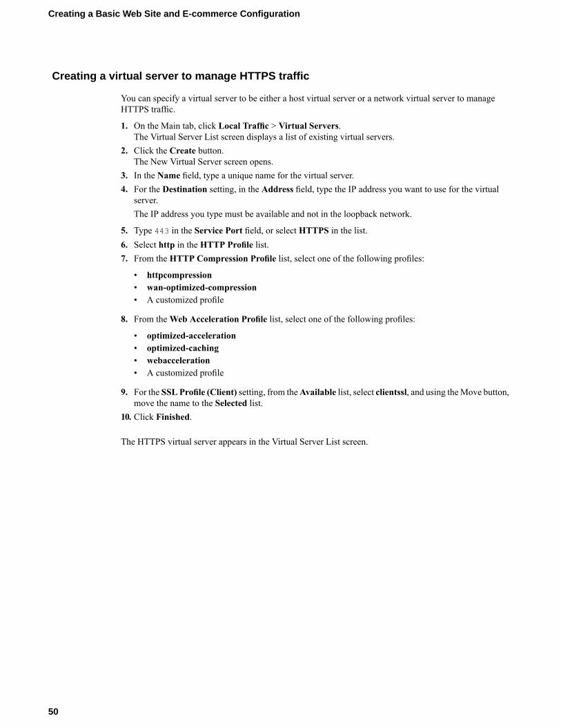
Creating a virtual server to manage HTTPS traffic
You can specify a virtual server to be either a host virtual server or a network virtual server to manageHTTPS traffic.
1. On the Main tab, click Local Traffic > Virtual Servers.The Virtual Server List screen displays a list of existing virtual servers.
2. Click the Create button.The New Virtual Server screen opens.
3. In the Name field, type a unique name for the virtual server.4. For the Destination setting, in the Address field, type the IP address you want to use for the virtual
server.The IP address you type must be available and not in the loopback network.
5. Type 443 in the Service Port field, or select HTTPS in the list.6. Select http in the HTTP Profile list.7. From the HTTP Compression Profile list, select one of the following profiles:
• httpcompression• wan-optimized-compression• A customized profile
8. From theWeb Acceleration Profile list, select one of the following profiles:
• optimized-acceleration• optimized-caching• webacceleration• A customized profile
9. For the SSL Profile (Client) setting, from theAvailable list, select clientssl, and using theMove button,move the name to the Selected list.
10. Click Finished.
The HTTPS virtual server appears in the Virtual Server List screen.
50
Creating a Basic Web Site and E-commerce Configuration

Installing a BIG-IP System Without Changing the IP Network
Overview: Installing a BIG-IP system without changing the IP network
A combination of several features of the BIG-IP®systemmakes it possible for you to place a BIG-IP systemin a network without changing the existing IP network. The following illustration shows the data centertopology before you add the BIG-IP system. The data center has one LAN, with one IP network, 10.0.0.0.The data center has one router to the Internet, two web servers, and a back-end mail server.
Figure 7: Data center example before adding a BIG-IP system
The existing data center structure does not support load balancing or high availability. The followingillustration shows an example of the data center topology after you add the BIG-IP system.
Figure 8: Data center example after adding a BIG-IP system
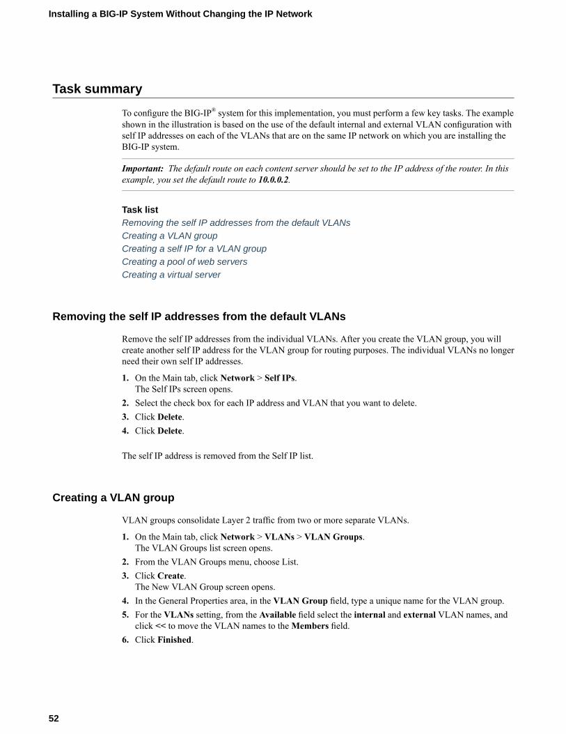
Task summary
To configure the BIG-IP® system for this implementation, you must perform a few key tasks. The exampleshown in the illustration is based on the use of the default internal and external VLAN configuration withself IP addresses on each of the VLANs that are on the same IP network on which you are installing theBIG-IP system.
Important: The default route on each content server should be set to the IP address of the router. In thisexample, you set the default route to 10.0.0.2.
Task listRemoving the self IP addresses from the default VLANsCreating a VLAN groupCreating a self IP for a VLAN groupCreating a pool of web serversCreating a virtual server
Removing the self IP addresses from the default VLANs
Remove the self IP addresses from the individual VLANs. After you create the VLAN group, you willcreate another self IP address for the VLAN group for routing purposes. The individual VLANs no longerneed their own self IP addresses.
1. On the Main tab, click Network > Self IPs.The Self IPs screen opens.
2. Select the check box for each IP address and VLAN that you want to delete.3. Click Delete.4. Click Delete.
The self IP address is removed from the Self IP list.
Creating a VLAN group
VLAN groups consolidate Layer 2 traffic from two or more separate VLANs.
1. On the Main tab, click Network > VLANs > VLAN Groups.The VLAN Groups list screen opens.
2. From the VLAN Groups menu, choose List.3. Click Create.
The New VLAN Group screen opens.4. In the General Properties area, in the VLAN Group field, type a unique name for the VLAN group.5. For the VLANs setting, from the Available field select the internal and external VLAN names, and
click << to move the VLAN names to theMembers field.6. Click Finished.
52
Installing a BIG-IP System Without Changing the IP Network

Creating a self IP for a VLAN group
You need at least one VLAN or VLAN group configured before you create a self IP address.
Self IP addresses enable the BIG-IP® system, and other devices on the network, to route application trafficthrough the associated VLAN or VLAN group.
1. On the Main tab, click Network > Self IPs.The Self IPs screen opens.
2. Click Create.The New Self IP screen opens.
3. In the IP Address field, type a self IP address for the VLAN group. In the example shown, this IPaddress is 10.0.0.6.
4. In the Netmask field, type the network mask for the specified IP address.5. From the VLAN list, select the name of the VLAN group you previously created.6. From the Port Lockdown list, select Allow Default.7. Click Finished.
The screen refreshes, and displays the new self IP address in the list.
The BIG-IP system can send and receive traffic through the specified VLAN or VLAN group.
Creating a pool of web servers
You can a create pool of web servers that you group together to receive and process traffic, to efficientlydistribute the load on your server resources.
1. On the Main tab, click Local Traffic > Pools.The Pool List screen opens.
2. Click Create.The New Pool screen opens.
3. In the Name field, type a unique name for the pool.4. In the Resources area of the screen, use the New Members setting to add the pool members. In our
example, pool members are 10.0.0.3:80 and 10.0.0.4:80.5. Click Finished.
The load balancing pool appears in the Pools list.
Creating a virtual server
A virtual server represents a destination IP address for application traffic.
1. On the Main tab, click Local Traffic > Virtual Servers.The Virtual Server List screen displays a list of existing virtual servers.
2. Click the Create button.The New Virtual Server screen opens.
3. In the Name field, type a unique name for the virtual server.4. In the Destination field, verify that the type of virtual server is Host, and in the Address field, type an
IP address. Continuing with our example, this address would be 10.0.0.5.
53
BIG-IP® Local Traffic Manager™: Implementations

5. From the Service Port list, select *All Ports.6. In the Resources area of the screen, from the Default Pool list, select a pool name.
You now have a destination IP address on the BIG-IP® system for application traffic.
54
Installing a BIG-IP System Without Changing the IP Network

Web Hosting Multiple Customers Using an External Switch
Overview: Web hosting multiple customers using an external switch
You can use the BIG-IP® system to provide hosting services, including application delivery, for multiplecustomers.
To host multiple web customers, you can incorporate an external switch into the configurations. In thisillustration, the BIG-IP system has an interface (5.1) assigned to three VLANs on a network. The threeVLANs are vlanA, vlanB, and vlanB. Interface 5.1 processes traffic for all three VLANs. Note that eachVLAN contains two servers, and serves a specific customer.
Tip: An alternate way to implement web hosting for multiple customers is to use the route domains feature.
Illustration for hosting multiple customers using an external switch
Task summary for hosting multiple customers
Perform these tasks to host multiple customers using an external switch.
Task listCreating a VLAN with a tagged interfaceCreating a load balancing pool

Creating a virtual server for HTTP traffic
Creating a VLAN with a tagged interface
When you create a VLANwith tagged interfaces, each of the specified interfaces can process traffic destinedfor that VLAN.
1. On the Main tab, click Network > VLANs.The VLAN List screen opens.
2. Click Create.The New VLAN screen opens.
3. In the Name field, type a unique name for the VLAN.4. In the Tag field, type a numeric tag, from 1 to 4094, for the VLAN. Leave the field blank if you want
the BIG-IP system to automatically assign a VLAN tag.The VLAN tag identifies the traffic from hosts in the associated VLAN.
5. For the Interfaces setting, click an interface number or trunk name from the Available list, and use theMove button to add the selected interface or trunk to the Tagged list. Repeat this step as necessary.You can use the same interface for other VLANs later, if you always assign the interface as a taggedinterface.
6. Select the Source Check check box if you want the system to verify that the return route to an initialpacket is the same VLAN from which the packet originated.
7. In theMTU field, retain the default number of bytes (1500).8. If you want to base redundant-system failover on VLAN-related events, select the Fail-safe box.9. Click Finished.
The screen refreshes, and displays the new VLAN in the list.
The new VLAN appears in the VLAN list.
Creating a load balancing pool
You can create a load balancing pool (a logical set of devices such as web servers that you group togetherto receive and process traffic) to efficiently distribute the load on your server resources.
Note: You must create the pool before you create the corresponding virtual server.
1. On the Main tab, click Local Traffic > Pools.The Pool List screen opens.
2. Click Create.The New Pool screen opens.
3. In the Name field, type a unique name for the pool.4. For the Health Monitors setting, in the Available list, select a monitor type, and click << to move the
monitor to the Active list.
Tip: Hold the Shift or Ctrl key to select more than one monitor at a time.
5. From the Load Balancing Method list, select how the system distributes traffic to members of thispool.The default is Round Robin.
56
Web Hosting Multiple Customers Using an External Switch

6. For the Priority Group Activation setting, specify how to handle priority groups:
• Select Disabled to disable priority groups. This is the default option.• Select Less than, and in the Available Members field, type the minimum number of members that
must remain available in each priority group in order for traffic to remain confined to that group.
7. Using the New Members setting, add each resource that you want to include in the pool:a) Either type an IP address in the Address field, or select a node address from the Node List.b) Type a port number in the Service Port field, or select a service name from the list.c) To specify a priority group, type a priority number in the Priority field.d) Click Add.
8. Click Finished.
The load balancing pool appears in the Pools list.
Creating a virtual server for HTTP traffic
This task creates a destination IP address for application traffic. As part of this task, you must assign therelevant pool to the virtual server.
1. On the Main tab, click Local Traffic > Virtual Servers.The Virtual Server List screen displays a list of existing virtual servers.
2. Click the Create button.The New Virtual Server screen opens.
3. In the Name field, type a unique name for the virtual server.4. For the Destination setting, in the Address field, type the IP address you want to use for the virtual
server.The IP address you type must be available and not in the loopback network.
5. In the Service Port field, type 80, or select HTTP from the list.6. From the HTTP Profile list, select http.7. In the Resources area of the screen, from the Default Pool list, select a pool name.8. Click Finished.
You now have a virtual server to use as a destination address for application traffic.
57
BIG-IP® Local Traffic Manager™: Implementations


Web Hosting Multiple Customers Using Untagged Interfaces
Overview: Web hosting multiple customers using untagged interfaces
One way to implement web hosting for multiple customers is to use multiple interfaces on the BIG-IP®
system to directly host traffic for multiple customers, without the need for an external switch. With thisscenario, you must configure the VLANs with untagged instead of tagged interfaces. As shown in thefollowing illustration, two BIG-IP system interfaces are assigned to each VLAN. For example, interfaces1.1 and 1.2 are assigned to VLAN vlanA. Each interface is assigned to a VLAN as an untagged interface.
Tip: An alternate way to implement web hosting for multiple customers is to use the route domains feature.
Illustration for hosting multiple customers using untagged interfaces
Task summary for hosting multiple customers
Perform these tasks to host multiple customers using tagged interfaces on VLANs.
Task listCreating a VLAN with an untagged interfaceCreating a load balancing poolCreating a virtual server for HTTP traffic

Creating a VLAN with an untagged interface
You can create a VLAN that uses untagged interfaces.
1. On the Main tab, click Network > VLANs.The VLAN List screen opens.
2. Click Create.The New VLAN screen opens.
3. In the Name field, type a unique name for the VLAN.4. In the Tag field, type a numeric tag, from 1 to 4094, for the VLAN. Leave the field blank if you want
the BIG-IP system to automatically assign a VLAN tag.The VLAN tag identifies the traffic from hosts in the associated VLAN.
5. For the Interfaces setting, from the Available list, click an interface number or trunk name and add theselected interface or trunk to the Untagged list. Repeat this step as necessary.
6. Click Finished.The screen refreshes, and displays the new VLAN in the list.
The interfaces that you specified in this task process traffic for this VLAN only.
Creating a load balancing pool
You can create a load balancing pool (a logical set of devices such as web servers that you group togetherto receive and process traffic) to efficiently distribute the load on your server resources.
Note: You must create the pool before you create the corresponding virtual server.
1. On the Main tab, click Local Traffic > Pools.The Pool List screen opens.
2. Click Create.The New Pool screen opens.
3. In the Name field, type a unique name for the pool.4. For the Health Monitors setting, in the Available list, select a monitor type, and click << to move the
monitor to the Active list.
Tip: Hold the Shift or Ctrl key to select more than one monitor at a time.
5. From the Load Balancing Method list, select how the system distributes traffic to members of thispool.The default is Round Robin.
6. For the Priority Group Activation setting, specify how to handle priority groups:
• Select Disabled to disable priority groups. This is the default option.• Select Less than, and in the Available Members field, type the minimum number of members that
must remain available in each priority group in order for traffic to remain confined to that group.
7. Using the New Members setting, add each resource that you want to include in the pool:a) Either type an IP address in the Address field, or select a node address from the Node List.b) Type a port number in the Service Port field, or select a service name from the list.
60
Web Hosting Multiple Customers Using Untagged Interfaces
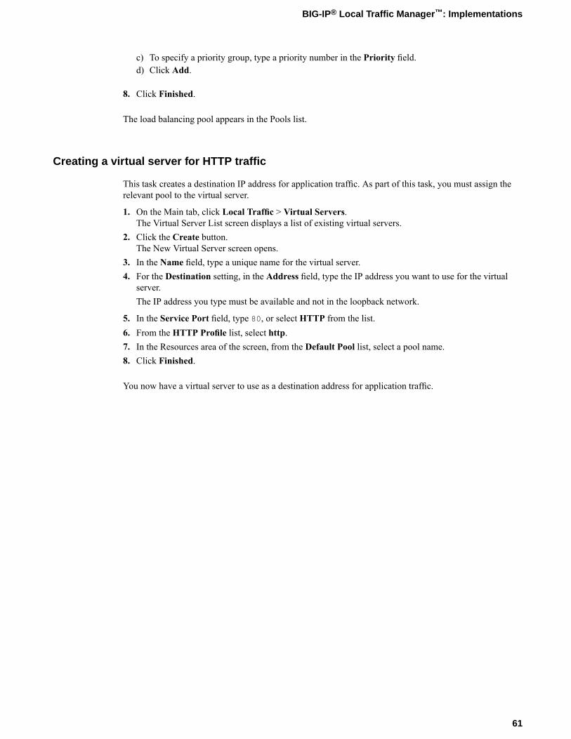
c) To specify a priority group, type a priority number in the Priority field.d) Click Add.
8. Click Finished.
The load balancing pool appears in the Pools list.
Creating a virtual server for HTTP traffic
This task creates a destination IP address for application traffic. As part of this task, you must assign therelevant pool to the virtual server.
1. On the Main tab, click Local Traffic > Virtual Servers.The Virtual Server List screen displays a list of existing virtual servers.
2. Click the Create button.The New Virtual Server screen opens.
3. In the Name field, type a unique name for the virtual server.4. For the Destination setting, in the Address field, type the IP address you want to use for the virtual
server.The IP address you type must be available and not in the loopback network.
5. In the Service Port field, type 80, or select HTTP from the list.6. From the HTTP Profile list, select http.7. In the Resources area of the screen, from the Default Pool list, select a pool name.8. Click Finished.
You now have a virtual server to use as a destination address for application traffic.
61
BIG-IP® Local Traffic Manager™: Implementations


Web Hosting Multiple Customers Using Route Domains
Overview: Use of route domains to host multiple web customers on theBIG-IP system
Using the route domains feature of the BIG-IP® system, you can provide hosting service for multiplecustomers by isolating each type of application traffic within a defined address space on the network. Thisenhances security and dedicates BIG-IP resources to each application.
Implementing route domains also allows you to use duplicate IP addresses on the network, as long as eachof the duplicate addresses resides in a separate route domain and is isolated on the network through a separateVLAN. For example, if you are processing traffic for two different customers, you can create two separateroute domains. The same node address (such as 10.0.10.1) can reside in each route domain, in the samepool or in different pools, and you can assign a different monitor to each of the two corresponding poolmembers.
A good example of the use of traffic isolation on a network is an ISP that services multiple customers, whereeach customer deploys a different application. The first illustration shows two route domain objects on aBIG-IP system, where each route domain corresponds to a separate customer, and thus, resides in its ownpartition. Within each partition, the ISP created the network objects and local traffic objects required forthat customer's application (AppA or AppB).
The sample configuration results in the BIG-IP system segmenting traffic for two different applications intotwo separate route domains. The routes for each application's traffic cannot cross route domain boundariesbecause cross-routing restrictions are enabled on the BIG-IP system by default. The second illustrationshows the resulting route isolation for AppA and AppB application traffic.

Illustration of sample BIG-IP configuration using route domains
Illustration of resulting route domain configuration
64
Web Hosting Multiple Customers Using Route Domains

Task summary
Perform these tasks to host multiple web customers using route domains.
Task listCreating an administrative partitionCreating a VLAN with a tagged interfaceCreating a self IP address for a default route domain in an administrative partitionCreating a route domain on a BIG-IP LTM systemCreating a load balancing poolCreating a virtual serverConfiguring route advertisement for a virtual addressAdding routes that specify VLAN internal as the resource
Creating an administrative partition
An administrative partition creates an access control boundary for users and applications.
1. On the Main tab, expand System and click Users.The Users List screen opens.
2. On the menu bar, click Partition List.3. Click Create.
The New Partition screen opens.4. Name the partition.5. (Optional) Type a description in the Description field.6. For the Device Group setting, choose an action:
ResultAction
Choose this option if you want the folder corresponding to this partition to inheritthe value of the device group attribute from folder root.
Retain thedefault value.
Choose this option if you do not want the folder corresponding to this partition toinherit the value of the device group attribute from folder root.
Clear the checkbox and selectthe name of adevice group.
7. For the Traffic Group setting, choose an action:ResultAction
Choose this option if you want the folder corresponding to this partition to inheritthe value of the traffic group attribute from folder root.
Retain the defaultvalue.
Choose this option if you do not want the folder corresponding to this partition toinherit the value of the traffic group attribute from folder root.
Clear the checkbox and select thename of a trafficgroup.
8. Click Finished.
65
BIG-IP® Local Traffic Manager™: Implementations

The new partition appears in the partition list.
Creating a VLAN with a tagged interface
When you create a VLANwith tagged interfaces, each of the specified interfaces can process traffic destinedfor that VLAN.
1. On the Main tab, click Network > VLANs.The VLAN List screen opens.
2. Click Create.The New VLAN screen opens.
3. In the Name field, type a unique name for the VLAN.4. In the Tag field, type a numeric tag, from 1 to 4094, for the VLAN. Leave the field blank if you want
the BIG-IP system to automatically assign a VLAN tag.The VLAN tag identifies the traffic from hosts in the associated VLAN.
5. For the Interfaces setting, click an interface number or trunk name from the Available list, and use theMove button to add the selected interface or trunk to the Tagged list. Repeat this step as necessary.You can use the same interface for other VLANs later, if you always assign the interface as a taggedinterface.
6. Select the Source Check check box if you want the system to verify that the return route to an initialpacket is the same VLAN from which the packet originated.
7. In theMTU field, retain the default number of bytes (1500).8. If you want to base redundant-system failover on VLAN-related events, select the Fail-safe box.9. Click Finished.
The screen refreshes, and displays the new VLAN in the list.
The new VLAN appears in the VLAN list.
Creating a self IP address for a default route domain in an administrative partition
Prerequisite: Ensure that you have created an internal VLAN and an external VLAN on the BIG-IP system.
Using this procedure, you must create two self IP addresses on the BIG-IP system. One self IP address isassociated with the internal VLAN, and the other is associated with the external VLAN. Self IP addressesenable the BIG-IP system and other devices on the network to route application traffic through the associatedVLAN.
1. On the Main tab, click Network > Self IPs.The Self IPs screen opens.
2. Click Create.The New Self IP screen opens.
3. In the IP Address field, type an IP address.This IP address should represent the address space of the VLAN that you specify with theVLAN setting.Because the route domain that you previously created is the default route domain for the administrativepartition, you do not need to append the route domain ID to this IP address.The system accepts IP addresses in both the IPv4 and IPv6 formats.
4. In the Netmask field, type the network mask for the specified IP address.5. From the VLAN/Tunnel list, select the VLAN to associate with this self IP address:
66
Web Hosting Multiple Customers Using Route Domains

• For the internal network, select the VLAN that is associated with an internal interface or trunk.• For the external network, select the VLAN that is associated with an external interface or trunk.• For the HA network, select the VLAN that is associated with an internal interface or trunk.
6. Click Finished.The screen refreshes, and displays the new self IP address in the list.
The BIG-IP system has a self IP address that is associated with the internal or external network.
Creating a route domain on a BIG-IP LTM system
Before you create a route domain, ensure that an external and internal VLAN exist on a BIG-IP® LTM®
system.
You can create a route domain on BIG-IP LTM to segment (isolate) network traffic on your network.
1. On the Main tab, click Network > Route Domains.The Route Domain List screen opens.
2. Click Create.The New Route Domain screen opens.
3. In the Name field, type a name for the route domain.This name must be unique within the administrative partition in which the route domain resides.
4. In the ID field, type an ID number for the route domain.This ID must be unique on the BIG-IP system; that is, no other route domain on the system can havethis ID.
5. In the Description field, type a description of the route domain.For example: This route domain applies to traffic for application MyApp.
6. For the Strict Isolation setting, select the Enabled check box to restrict traffic in this route domainfrom crossing into another route domain.
7. For the Parent Name setting, retain the default value.8. For the VLANs setting, from the Available list, select a VLAN name and move it to theMembers list.
Select the VLAN that processes the application traffic relevant to this route domain.Configuring this setting ensures that the BIG-IP system immediately associates any self IP addressespertaining to the selected VLANs with this route domain.
9. For theDynamic Routing Protocols setting, from theAvailable list, select one or more protocol namesand move them to the Enabled list.You can enable any number of listed protocols for this route domain. This setting is optional.
10. From the Partition Default Route Domain list, select eitherAnother route domain (0) is the PartitionDefault Route Domain orMake this route domain the Partition Default Route Domain.This setting does not appear if the current administrative partition is partition Common.When you configure this setting, either route domain 0 or this route domain becomes the default routedomain for the current administrative partition.
11. Click Finished.The system displays a list of route domains on the BIG-IP system.
You now have another route domain on the BIG-IP system.Task summaryCreating a self IP address for a default route domain in an administrative partitionCreating a load balancing pool
67
BIG-IP® Local Traffic Manager™: Implementations

Creating a load balancing pool
You can create a load balancing pool (a logical set of devices such as web servers that you group togetherto receive and process traffic) to efficiently distribute the load on your server resources.
Note: You must create the pool before you create the corresponding virtual server.
1. On the Main tab, click Local Traffic > Pools.The Pool List screen opens.
2. Click Create.The New Pool screen opens.
3. In the Name field, type a unique name for the pool.4. For the Health Monitors setting, in the Available list, select a monitor type, and click << to move the
monitor to the Active list.
Tip: Hold the Shift or Ctrl key to select more than one monitor at a time.
5. From the Load Balancing Method list, select how the system distributes traffic to members of thispool.The default is Round Robin.
6. For the Priority Group Activation setting, specify how to handle priority groups:
• Select Disabled to disable priority groups. This is the default option.• Select Less than, and in the Available Members field, type the minimum number of members that
must remain available in each priority group in order for traffic to remain confined to that group.
7. Using the New Members setting, add each resource that you want to include in the pool:a) Either type an IP address in the Address field, or select a node address from the Node List.b) Type a port number in the Service Port field, or select a service name from the list.c) To specify a priority group, type a priority number in the Priority field.d) Click Add.
8. Click Finished.
The load balancing pool appears in the Pools list.
Creating a virtual server
A virtual server represents a destination IP address for application traffic.
1. On the Main tab, click Local Traffic > Virtual Servers.The Virtual Server List screen displays a list of existing virtual servers.
2. Click the Create button.The New Virtual Server screen opens.
3. In the Name field, type a unique name for the virtual server.4. For the Destination setting, in the Address field, type the IP address you want to use for the virtual
server.The IP address you type must be available and not in the loopback network.
5. For the Service Port setting, type a port number in the field, or select a service name from the list.
68
Web Hosting Multiple Customers Using Route Domains

6. In the Resources area of the screen, from the Default Pool list, select a pool name.
The web customer now has a destination IP address on the BIG-IP system for application traffic.
Configuring route advertisement for a virtual address
Before configuring route advertisement on a virtual address, verify that you have enabled one or moredynamic routing protocols on the route domain pertaining to this virtual address. Also verify that you haveconfigured the relevant dynamic routing protocols for route redistribution.
Perform this task to advertise a route for this virtual address to other routers on your network.
Important: This task pertains only to configurations for which you have enabled dynamic routing protocolson the relevant route domain. If you have not enabled dynamic routing protocols on the relevant routedomain, you can skip this task.
1. On the Main tab, click Local Traffic > Virtual Servers > Virtual Address List.The Virtual Address List screen opens.
2. In the Name column, click the virtual address for which you want to advertise a route.This displays the properties of that virtual address.
3. Verify that the ARP field is selected.4. From the Advertise Route list, choose one of these options:
DescriptionOption
Specifies that the system advertises a route for this virtual IP addresswhenever any virtual server associated with this virtual IP address isavailable.
When any virtual server isavailable
Specifies that the system advertises a route for this virtual IP addresswhenever all virtual servers associated with this virtual IP address isavailable.
When all virtual servers(s)are available
Specifies that the system always advertises a route for this virtual IPaddress.
Always
5. For the Route Advertisement setting, select the box.This makes it possible for the BIG-IP system to advertise this virtual IP address when you have enabledany dynamic routing protocols.
6. Click Update.7. Repeat this task for each virtual address for which you want to advertise a route.
The BIG-IP system advertises a route for this virtual address to other routers when one or more dynamicrouting protocols are enabled and are configured for route redistribution.Task summaryCreating a virtual serverAdding routes that specify VLAN internal as the resource
Adding routes that specify VLAN internal as the resource
Ensure that you set the current administrative partition to the partition in which you want a specific customer'sconfiguration to reside.
69
BIG-IP® Local Traffic Manager™: Implementations
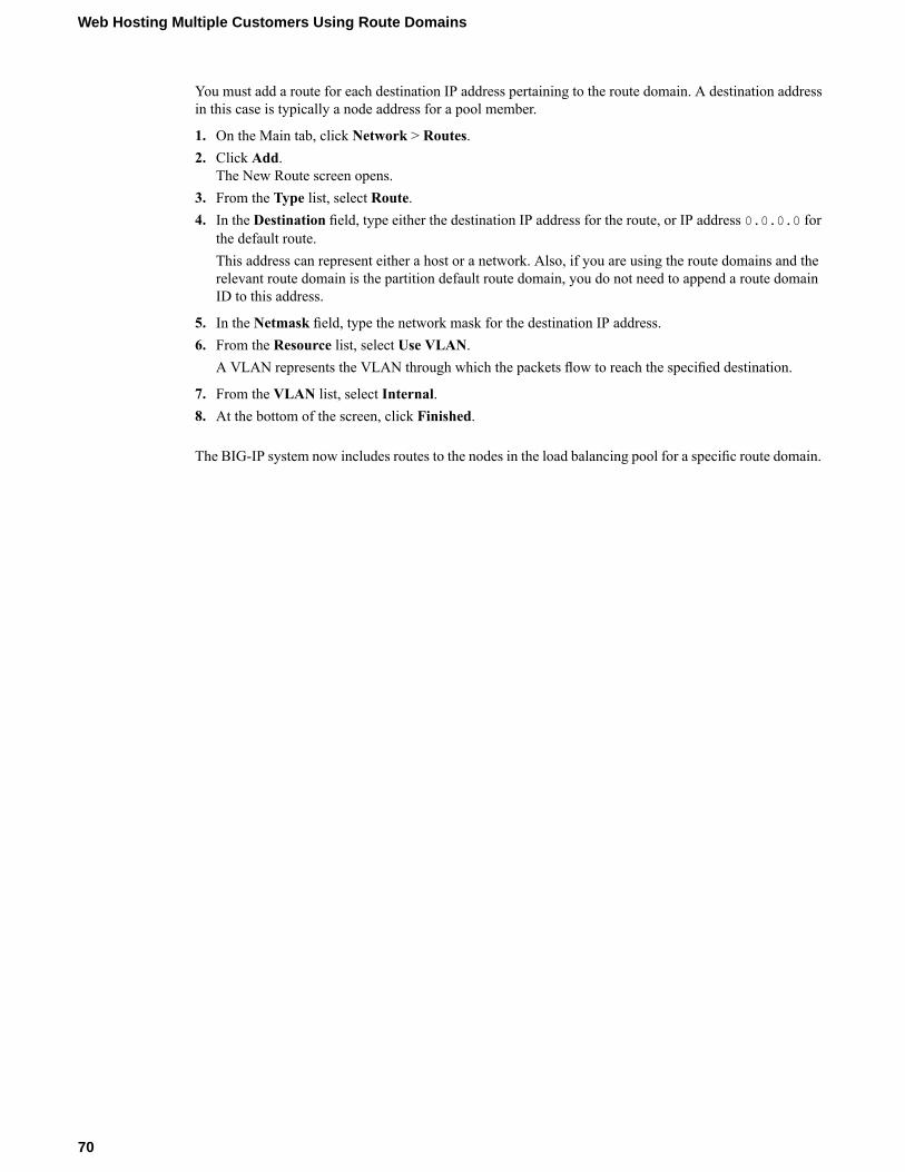
You must add a route for each destination IP address pertaining to the route domain. A destination addressin this case is typically a node address for a pool member.
1. On the Main tab, click Network > Routes.2. Click Add.
The New Route screen opens.3. From the Type list, select Route.4. In the Destination field, type either the destination IP address for the route, or IP address 0.0.0.0 for
the default route.This address can represent either a host or a network. Also, if you are using the route domains and therelevant route domain is the partition default route domain, you do not need to append a route domainID to this address.
5. In the Netmask field, type the network mask for the destination IP address.6. From the Resource list, select Use VLAN.
A VLAN represents the VLAN through which the packets flow to reach the specified destination.
7. From the VLAN list, select Internal.8. At the bottom of the screen, click Finished.
The BIG-IP system now includes routes to the nodes in the load balancing pool for a specific route domain.
70
Web Hosting Multiple Customers Using Route Domains

Enabling IP Address Intelligence
Overview: Enabling IP address intelligence
An IP intelligence database is a list of IP addresses with questionable reputations. IP addresses gain aquestionable reputation and are added to the database as a result of having performed exploits or attacks,or these addresses might represent proxy servers, scanners, or systems that have been infected. You canprevent system attacks by excluding traffic from malicious IP addresses. The IP Intelligence database ismaintained online by a third party.
The BIG-IP® system can connect to an IP intelligence database, download the contents, and automaticallykeep the database up to date. You use iRules® to instruct the system on how to use IP address intelligenceinformation. For example, iRules can instruct the system to verify the reputation of and log the originatingIP address of all requests.
You can also use the IP address intelligence information within security policies in the Application SecurityManager™ to log or block requests from IP addresses with questionable reputations.
Task summaryEnabling IP address intelligenceCreating an iRule to log IP address intelligence informationCreating an iRule to reject requests with questionable IP addressesChecking the reputation of an IP addressChecking the status of the IP intelligence database
Enabling IP address intelligence
The requirements for using IP address intelligence are:
• The system must have an IP Intelligence license.• The system must have an Internet connection either directly or through a proxy server.• The system must have DNS configured (go to System > Configuration > Device > DNS).
Important: IP address intelligence is enabled by default. You only need to enable it if it was previouslydisabled.
To enable IP address intelligence on the BIG-IP® system, you enable auto-update to connect the system tothe IP intelligence database.
1. Log in to the command line for the BIG-IP® system.2. To determine whether IP intelligence is enabled, type the following command: tmsh list sys db
iprep.autoupdateIf the value of the iprep.autoupdate variable is disable, IP intelligence is not enabled. If it isenable, your task is complete.
3. At the prompt, type tmsh modify sys db iprep.autoupdate value enable
The system downloads the IP intelligence database and stores it in the binary file,/var/IpRep/F5IpRep.dat. It is updated every 5 minutes.

4. If the BIG-IP system is behind a firewall, make sure that the BIG-IP system has external access tovector.brightcloud.com using port 443. That is the IP Intelligence server from which the systemgets IP Intelligence information.
5. (Optional) If the BIG-IP system connects to the Internet using a forward proxy server, set these systemdatabase variables.a) Type tmsh modify sys db proxy.host value hostname to specify the hostname of the
proxy server.b) Type tmsh modify sys db proxy.port value port_number to specify the port number of
the proxy server.c) Type tmsh modify sys db proxy.username value hostname to specify the user name to
log in to the proxy server.d) Type tmsh modify sys db proxy.password value password to specify the password to
log in to the proxy server.
The IP address intelligence feature remains enabled unless you disable it with the command tmsh modifysys db iprep.autoupdate value disable.
You can create iRules® to instruct the system how to handle traffic from IP addresses with questionablereputations, or use Application Security Manager™ to configure IP address intelligence blocking.
Creating an iRule to log IP address intelligence information
Before you can create an iRule to log IP address intelligence information, your systemmust have IP addressintelligence enabled.
You use iRules® to log IP address intelligence categories to the file /var/log/ltm. This is an example ofthe type of iRule you can write.
1. On the Main tab, click Local Traffic > iRules.The iRule List screen opens, displaying any existing iRules.
2. Click Create.The New iRule screen opens.
3. In the Name field, type a name between 1 and 31 characters, such as my_iRule.4. In the Definition field, type the iRule using Tool Command Language (Tcl) syntax.
For example, to log all IP addresses and any associated IP address intelligence categories, type thefollowing iRule:
when CLIENT_ACCEPTED {log local0. "IP Address Intelligence for IP address
[IP::client_addr]:[IP::reputation [IP::client_addr]]"
}
5. Click Finished.The new iRule appears in the list of iRules on the system.
When traffic is received from an IP address with a questionable reputation and that is included in the IPintelligence database, the system prints the IP address intelligence information in the /var/log/ltm log.
For complete and detailed information about iRules syntax, see the F5 Networks DevCentral web site,http://devcentral.f5.com.
72
Enabling IP Address Intelligence

Creating an iRule to reject requests with questionable IP addresses
Before you can create an iRule to reject requests based on an IP address reputation, your system must haveIP address intelligence enabled.
You can use iRules® to reject requests from IP addresses that have questionable reputations and are listedin the IP intelligence database. This is an example of the type of iRule you can write.
1. On the Main tab, click Local Traffic > iRules.The iRule List screen opens, displaying any existing iRules.
2. Click Create.The New iRule screen opens.
3. In the Name field, type a name between 1 and 31 characters, such as my_iRule.4. In the Definition field, type the iRule using Tool Command Language (Tcl) syntax.
For example, to reject requests from IP addresses listed in the IP intelligence database because theycould be Windows Exploits or Web Attacks, type the following iRule:
when HTTP_REQUEST {set ip_reputation_categories [IP::reputation [IP::client_addr]]set is_reject 0if {($ip_reputation_categories contains "Windows Exploits")} {
set is_reject 1}if {($ip_reputation_categories contains "Web Attacks")} {
set is_reject 1}if {($is_reject)} {
log local0. "Attempted access from malicious IP address[IP::client_addr]
($ip_reputation_categories), request was rejected"HTTP::respond 200 content"<HTML><HEAD><TITLE>Rejected Request</TITLE></HEAD><BODY>The request was rejected. <BR>Attempted access from malicious IP address</BODY></HTML>"
}}
5. Click Finished.The new iRule appears in the list of iRules on the system.
When traffic is received from an IP address with a questionable reputation that is included in the IPintelligence database, the system prints the IP address intelligence information in the /var/log/ltm log.
For complete and detailed information about iRules syntax, see the F5 Networks DevCentral web site,http://devcentral.f5.com.
Checking the reputation of an IP address
Before you can check the reputation of an IP address, your systemmust have IP address intelligence enabled.
You can verify the reputation of a specific IP address.
1. Log in to the command line for the BIG-IP® system.2. At the prompt, type iprep_lookup IP_addresswhere IP_address is the address whose reputation
you want to verify.
73
BIG-IP® Local Traffic Manager™: Implementations

For example, to verify 1.1.1.1:
iprep_lookup 1.1.1.1opening database in /var/IpRep/F5IpRep.datsize of IP reputation database = 41693298iprep threats list for ip = 1.1.1.1 is:
bit 4 - Scannersbit 5 - Denial of Service
The system looks up the IP address, and if it is in the database, the command output displays the IPaddress intelligence categories that show the reason. In this case, 1.1.1.1 is a source of potential portor network scans and DoS attacks. If the IP address is not found in the IP intelligence database, thesystem returns the message iprep_lookup not found for ip = <ip_address>.
Checking the status of the IP intelligence database
You can display the status of the IP Intelligence database to learn when it was last updated and the numberof questionable IP addresses it contains.
1. Log in to the command line for the BIG-IP® system.2. To display IP intelligence database status, type tmsh show sys iprep-status.
The system displays the status. For example:
-----------------------------------------------------------------------Sys::IP Reputation Database Status-----------------------------------------------------------------------Last time the server was contacted for updates 04/21/2012 09:33:31Last time an update was received 04/21/2012 09:33:31Total number of IP Addresses in the database 5516336Number of IP Addresses received in the last update 136
IP address intelligence categories
Along with the IP address, the IP intelligence database stores the category that explains the reason that theIP address is considered untrustworthy.
DescriptionCategory
IP addresses that have exercised various exploitsagainst Windows resources using browsers,
Windows exploits
programs, downloaded files, scripts, or operatingsystem vulnerabilities.
IP addresses that have launched web attacks ofvarious forms.
Web attacks
IP addresses of computers that are infected withmalicious software and are controlled as a group,
Botnets
and are now part of a botnet. Hackers can exploitbotnets to send spam messages, launch various
74
Enabling IP Address Intelligence

DescriptionCategoryattacks, or cause target systems to behave in otherunpredictable ways.
IP addresses that have been observed to perform portscans or network scans, typically to identifyvulnerabilities for later exploits.
Scanners
IP addresses that have launched Denial of Service(DoS) attacks. These attacks are usually requests for
Denial of Service
legitimate services, but occur at such a fast rate thattargeted systems cannot respond and become boggeddown or unable to service legitimate clients.
IP addresses that issue HTTP requests with a lowreputation index score, or are known malware sites.
Infected Sources
IP addresses that are associated with phishing websites that masquerade as legitimate web sites.
Phishing
IP addresses that are associated with web proxiesthat shield the originator's IP address (such asanonymous proxies).
Proxy
75
BIG-IP® Local Traffic Manager™: Implementations


Managing Client-side HTTPS Traffic Using a Self-signedCertificate
Overview: Managing client-side HTTPS traffic using a self-signed certificate
When you want to manage HTTP traffic over SSL, you can configure the BIG-IP® system to perform theSSL handshake that target web servers typically perform.
A common way to configure the BIG-IP system is to enable client-side SSL, which makes it possible forthe system to decrypt client requests before forwarding them to a server, and to encrypt server responsesbefore returning them to the client. In this case, you need to install only one SSL key/certificate pair on theBIG-IP system.
This implementation uses a self-signed certificate to authenticate HTTPS traffic.
Task summary
To implement client-side authentication using HTTP and SSL with a self-signed certificate, you perform afew basic configuration tasks.
Task listCreating a self-signed SSL certificateCreating a custom HTTP service profileCreating a custom Client SSL profileCreating a pool to manage HTTP trafficCreating a virtual server for client-side HTTPS traffic
Creating a self-signed SSL certificate
If you are configuring the BIG-IP system to manage client-side HTTP traffic, you create a self-signedcertificate to authenticate and secure the client-side HTTP traffic. If you are also configuring the system tomanage server-side HTTP traffic, you create a second self-signed certificate to authenticate and secure theserver-side HTTP traffic.
1. On the Main tab, click Local Traffic > SSL Certificates.This displays a list of existing SSL certificates.
2. On the upper-right corner of the screen, click Create.3. In the Name field, type a name for the certificate, such as my_clientside_cert or
my_serverside_cert.4. From the Issuer list, select Self.5. In the Common Name field, type either the IP address for the virtual server you will create later on, or
a DNS name that resolves to the virtual server’s IP address.

6. In the Division field, type your company name.7. In the Organization field, type your department name.8. In the Locality field, type your city name.9. In the State or Province field, type your state or province name.10. From the Country list, select the name of your country.11. In the E-mail Address field, type your email address.12. In the Challenge Password field, type a password.13. In the Confirm Password field, re-type the password you typed in the Challenge Password field.14. In the Key Properties area of the screen, from the Size list, select 1024.15. Click Finished.
Creating a custom HTTP service profile
An HTTP profile defines the way that you want the BIG-IP®system to manage HTTP traffic.
Note: Other HTTP profile types (HTTP Compression and Web Acceleration) enable you to configurecompression and cache settings, as required. Use of these profile types is optional.
1. On the Main tab, click Local Traffic > Profiles > Services > HTTP.The HTTP profile list screen opens.
2. Click Create.The New HTTP Profile screen opens.
3. In the Name field, type a name for the profile.4. From the Parent Profile list, select http.5. Select the Custom check box.
The fields in the Settings area become available for revision.6. Modify the settings, as required.7. Click Finished.
The custom HTTP profile now appears in the HTTP profile list screen.
Creating a custom Client SSL profile
A Client SSL profile makes it possible for the BIG-IP® system to perform decryption and encryption forclient-side SSL traffic.
1. On the Main tab, click Local Traffic > Profiles > SSL > Client.The Client profile list screen opens.
2. Click Create.The New Client SSL Profile screen opens.
3. In the Name field, type a name for the profile.4. Select clientssl in the Parent Profile list.5. From the Configuration list, select Advanced.
This selection makes it possible for you to modify additional default settings.
6. Select the Custom check box for Configuration.The settings in the Configuration area become available for configuring.
78
Managing Client-side HTTPS Traffic Using a Self-signed Certificate
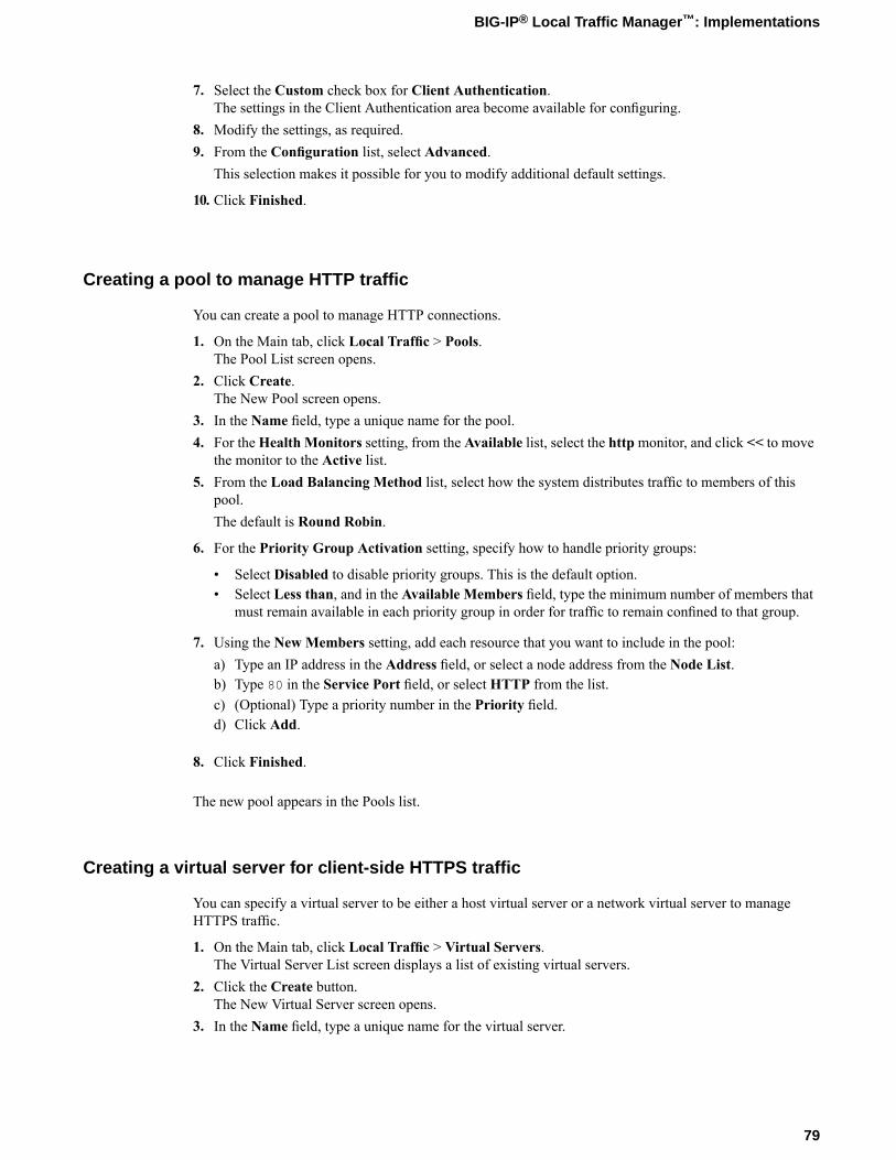
7. Select the Custom check box for Client Authentication.The settings in the Client Authentication area become available for configuring.
8. Modify the settings, as required.9. From the Configuration list, select Advanced.
This selection makes it possible for you to modify additional default settings.
10. Click Finished.
Creating a pool to manage HTTP traffic
You can create a pool to manage HTTP connections.
1. On the Main tab, click Local Traffic > Pools.The Pool List screen opens.
2. Click Create.The New Pool screen opens.
3. In the Name field, type a unique name for the pool.4. For theHealth Monitors setting, from the Available list, select the httpmonitor, and click << to move
the monitor to the Active list.5. From the Load Balancing Method list, select how the system distributes traffic to members of this
pool.The default is Round Robin.
6. For the Priority Group Activation setting, specify how to handle priority groups:
• Select Disabled to disable priority groups. This is the default option.• Select Less than, and in the Available Members field, type the minimum number of members that
must remain available in each priority group in order for traffic to remain confined to that group.
7. Using the New Members setting, add each resource that you want to include in the pool:a) Type an IP address in the Address field, or select a node address from the Node List.b) Type 80 in the Service Port field, or select HTTP from the list.c) (Optional) Type a priority number in the Priority field.d) Click Add.
8. Click Finished.
The new pool appears in the Pools list.
Creating a virtual server for client-side HTTPS traffic
You can specify a virtual server to be either a host virtual server or a network virtual server to manageHTTPS traffic.
1. On the Main tab, click Local Traffic > Virtual Servers.The Virtual Server List screen displays a list of existing virtual servers.
2. Click the Create button.The New Virtual Server screen opens.
3. In the Name field, type a unique name for the virtual server.
79
BIG-IP® Local Traffic Manager™: Implementations

4. For the Destination setting, in the Address field, type the IP address you want to use for the virtualserver.The IP address you type must be available and not in the loopback network.
5. Type 443 in the Service Port field, or select HTTPS from the list.6. From the HTTP Profile list, select the HTTP profile that you previously created.7. For the SSL Profile (Client) setting, from the Available list, select the name of the Client SSL profile
you previously created, and using the Move button, move the name to the Selected list.8. Click Finished.
The HTTPS virtual server appears in the Virtual Server List screen.
Implementation result
After you complete the tasks in this implementation, the BIG-IP® system can authenticate and decryptHTTPS traffic coming from a client system. The BIG-IP system can also re-encrypt server responses beforesending them back to the client.
80
Managing Client-side HTTPS Traffic Using a Self-signed Certificate

Managing Client and Server HTTPS Traffic using aSelf-signed Certificate
Overview: Managing client and server HTTPS traffic using a self-signedcertificate
One of the ways to configure the BIG-IP system to manage SSL traffic is to enable both client-side andserver-side SSL termination:
• Client-side SSL termination makes it possible for the system to decrypt client requests before sendingthem on to a server, and encrypt server responses before sending them back to the client. This ensuresthat client-side HTTPS traffic is encrypted. In this case, you need to install only one SSL key/certificatepair on the BIG-IP system.
• Server-side SSL termination makes it possible for the system to decrypt and then re-encrypt clientrequests before sending them on to a server. Server-side SSL termination also decrypts server responsesand then re-encrypts them before sending them back to the client. This ensures security for both client-and server-side HTTPS traffic. In this case, you need to install two SSL key/certificate pairs on theBIG-IP system. The system uses the first certificate/key pair to authenticate the client, and uses thesecond pair to request authentication from the server.
This implementation uses a self-signed certificate to authenticate HTTPS traffic.
Task summary
To implement client-side and server-side authentication using HTTP and SSL with a self-signed certificate,you perform a few basic configuration tasks.
Task listCreating a self-signed SSL certificateCreating a custom HTTP service profileCreating a custom Client SSL profileCreating a custom Server SSL profileCreating a pool to manage HTTPS trafficCreating a virtual server for client-side and server-side HTTPS traffic
Creating a self-signed SSL certificate
If you are configuring the BIG-IP system to manage client-side HTTP traffic, you create a self-signedcertificate to authenticate and secure the client-side HTTP traffic. If you are also configuring the system tomanage server-side HTTP traffic, you create a second self-signed certificate to authenticate and secure theserver-side HTTP traffic.
1. On the Main tab, click Local Traffic > SSL Certificates.

This displays a list of existing SSL certificates.2. On the upper-right corner of the screen, click Create.3. In the Name field, type a name for the certificate, such as my_clientside_cert or
my_serverside_cert.4. From the Issuer list, select Self.5. In the Common Name field, type either the IP address for the virtual server you will create later on, or
a DNS name that resolves to the virtual server’s IP address.6. In the Division field, type your company name.7. In the Organization field, type your department name.8. In the Locality field, type your city name.9. In the State or Province field, type your state or province name.10. From the Country list, select the name of your country.11. In the E-mail Address field, type your email address.12. In the Challenge Password field, type a password.13. In the Confirm Password field, re-type the password you typed in the Challenge Password field.14. In the Key Properties area of the screen, from the Size list, select 1024.15. Click Finished.
Creating a custom HTTP service profile
An HTTP profile defines the way that you want the BIG-IP®system to manage HTTP traffic.
Note: Other HTTP profile types (HTTP Compression and Web Acceleration) enable you to configurecompression and cache settings, as required. Use of these profile types is optional.
1. On the Main tab, click Local Traffic > Profiles > Services > HTTP.The HTTP profile list screen opens.
2. Click Create.The New HTTP Profile screen opens.
3. In the Name field, type a name for the profile.4. From the Parent Profile list, select http.5. Select the Custom check box.
The fields in the Settings area become available for revision.6. Modify the settings, as required.7. Click Finished.
The custom HTTP profile now appears in the HTTP profile list screen.
Creating a custom Client SSL profile
A Client SSL profile makes it possible for the BIG-IP® system to perform decryption and encryption forclient-side SSL traffic.
1. On the Main tab, click Local Traffic > Profiles > SSL > Client.The Client profile list screen opens.
2. Click Create.
82
Managing Client and Server HTTPS Traffic using a Self-signed Certificate

The New Client SSL Profile screen opens.3. In the Name field, type a name for the profile.4. Select clientssl in the Parent Profile list.5. From the Configuration list, select Advanced.
This selection makes it possible for you to modify additional default settings.
6. Select the Custom check box for Configuration.The settings in the Configuration area become available for configuring.
7. Select the Custom check box for Client Authentication.The settings in the Client Authentication area become available for configuring.
8. Modify the settings, as required.9. From the Configuration list, select Advanced.
This selection makes it possible for you to modify additional default settings.
10. Click Finished.
Creating a custom Server SSL profile
A Server SSL profile enables the BIG-IP® system to perform decryption and encryption for server-side SSLtraffic.
1. On the Main tab, click Local Traffic > Profiles > SSL > Server.The SSL Server profile list screen opens.
2. Click Create.The New Server SSL Profile screen opens.
3. In the Name field, type a name for the profile.4. Select serverssl in the Parent Profile list.5. From the Configuration list, select Advanced.
This selection makes it possible for you to modify additional default settings.
6. Select the Custom check box for Configuration.The settings in the Configuration area become available for configuring.
7. Select the Custom check box for Server Authentication.The settings in the Server Authentication area become available for configuring.
8. Modify the settings, as required.9. Click Finished.
The custom Server SSL profile is listed in the Profiles:SSL:Server list.
Creating a pool to manage HTTPS traffic
You can create a pool (a logical set of devices, such as web servers, that you group together to receive andprocess HTTPS traffic) to efficiently distribute the load on your server resources.
1. On the Main tab, click Local Traffic > Pools.The Pool List screen opens.
2. Click Create.The New Pool screen opens.
3. In the Name field, type a unique name for the pool.
83
BIG-IP® Local Traffic Manager™: Implementations

4. Assign the https or https_443 health monitor from the Available list by moving it to the Active list.5. From the Load Balancing Method list, select how the system distributes traffic to members of this
pool.The default is Round Robin.
6. For the Priority Group Activation setting, specify how to handle priority groups:
• Select Disabled to disable priority groups. This is the default option.• Select Less than, and in the Available Members field, type the minimum number of members that
must remain available in each priority group in order for traffic to remain confined to that group.
7. Add each resource that you want to include in the pool using the New Members setting:a) Type an IP address in the Address field, or select a node address from the Node List.b) Type 443 in the Service Port field, or select HTTPS from the list.c) (Optional) Type a priority number in the Priority field.d) Click Add.
8. Click Finished.
The HTTPS load balancing pool now appears in the Pool List screen.
Creating a virtual server for client-side and server-side HTTPS traffic
You can specify a virtual server to be either a host virtual server or a network virtual server to manageHTTPS traffic.
1. On the Main tab, click Local Traffic > Virtual Servers.The Virtual Server List screen displays a list of existing virtual servers.
2. Click the Create button.The New Virtual Server screen opens.
3. In the Name field, type a unique name for the virtual server.4. For the Destination setting, in the Address field, type the IP address you want to use for the virtual
server.The IP address you type must be available and not in the loopback network.
5. Type 443 in the Service Port field, or select HTTPS from the list.6. For the HTTP Profile setting, verify that the default HTTP profile, http, is selected.7. For the SSL Profile (Client) setting, from the Available list, select the name of the Client SSL profile
you previously created, and using the Move button, move the name to the Selected list.8. For the SSL Profile (Server) setting, from the Available list, select the name of the Server SSL profile
you previously created, and using the Move button, move the name to the Selected list.9. Click Finished.
The HTTPS virtual server now appears in the Virtual Server List screen.
84
Managing Client and Server HTTPS Traffic using a Self-signed Certificate

Implementation results
After you complete the tasks in this implementation, the BIG-IP® system ensures that SSL authenticationand encryption occurs for both client-side and server-side HTTP traffic. The system performs these operationsaccording to the values you specify in the Client SSL and Server SSL profiles.
85
BIG-IP® Local Traffic Manager™: Implementations


Managing Client-side HTTPS Traffic using a CA-signedCertificate
Overview: Managing client-side HTTPS traffic using a CA-signed certificate
When you want to manage HTTP traffic over SSL, you can configure the BIG-IP® system to perform theSSL handshake that target web servers normally perform.
A common way to configure the BIG-IP system is to enable client-side SSL, which makes it possible forthe system to decrypt client requests before sending them on to a server, and encrypt server responses beforesending them back to the client. In this case, you need to install only one SSL key/certificate pair on theBIG-IP system.
This implementation uses a certificate signed by a certificate authority (CA) to authenticate HTTPS traffic.
Task summary
To implement client-side authentication using HTTP and SSL with a certificate signed by a certificateauthority, you perform a few basic configuration tasks.
Task listRequesting a certificate from a certificate authorityCreating a custom HTTP service profileCreating a custom Client SSL profileCreating a pool to manage HTTP trafficCreating a virtual server for client-side HTTPS traffic
Requesting a certificate from a certificate authority
You can generate a certificate and copy it or submit it to a trusted certificate authority for signature.
1. On the Main tab, click Local Traffic > SSL Certificate List.The SSL Certificate List screen opens.
2. Click Create.3. Name the SSL certificate with a unique name.4. In the Issuer list, select Certificate Authority.5. In the Common Name field, type a name.6. Configure any additional Certificate Properties settings, as necessary.7. For Key Properties, in the Size list, select a size in bits.8. Click Finished.9. Do one of the following to download the request into a file on your system.

• In the Request Text field, copy the certificate.• For Request File, click the button.
10. Follow the instructions on the web site for either pasting the copied request or attaching the generatedrequest file.
11. Click Finished.
The generated certificate is submitted to a trusted certificate authority for signature.
Creating a custom HTTP service profile
An HTTP profile defines the way that you want the BIG-IP®system to manage HTTP traffic.
Note: Other HTTP profile types (HTTP Compression and Web Acceleration) enable you to configurecompression and cache settings, as required. Use of these profile types is optional.
1. On the Main tab, click Local Traffic > Profiles > Services > HTTP.The HTTP profile list screen opens.
2. Click Create.The New HTTP Profile screen opens.
3. In the Name field, type a name for the profile.4. From the Parent Profile list, select http.5. Select the Custom check box.
The fields in the Settings area become available for revision.6. Modify the settings, as required.7. Click Finished.
The custom HTTP profile now appears in the HTTP profile list screen.
Creating a custom Client SSL profile
A Client SSL profile makes it possible for the BIG-IP® system to perform decryption and encryption forclient-side SSL traffic.
1. On the Main tab, click Local Traffic > Profiles > SSL > Client.The Client profile list screen opens.
2. Click Create.The New Client SSL Profile screen opens.
3. In the Name field, type a name for the profile.4. Select clientssl in the Parent Profile list.5. From the Configuration list, select Advanced.
This selection makes it possible for you to modify additional default settings.
6. Select the Custom check box for Configuration.The settings in the Configuration area become available for configuring.
7. Select the Custom check box for Client Authentication.The settings in the Client Authentication area become available for configuring.
8. Modify the settings, as required.9. From the Configuration list, select Advanced.
88
Managing Client-side HTTPS Traffic using a CA-signed Certificate

This selection makes it possible for you to modify additional default settings.
10. Click Finished.
Creating a pool to manage HTTP traffic
You can create a pool to manage HTTP connections.
1. On the Main tab, click Local Traffic > Pools.The Pool List screen opens.
2. Click Create.The New Pool screen opens.
3. In the Name field, type a unique name for the pool.4. For theHealth Monitors setting, from the Available list, select the httpmonitor, and click << to move
the monitor to the Active list.5. From the Load Balancing Method list, select how the system distributes traffic to members of this
pool.The default is Round Robin.
6. For the Priority Group Activation setting, specify how to handle priority groups:
• Select Disabled to disable priority groups. This is the default option.• Select Less than, and in the Available Members field, type the minimum number of members that
must remain available in each priority group in order for traffic to remain confined to that group.
7. Using the New Members setting, add each resource that you want to include in the pool:a) Type an IP address in the Address field, or select a node address from the Node List.b) Type 80 in the Service Port field, or select HTTP from the list.c) (Optional) Type a priority number in the Priority field.d) Click Add.
8. Click Finished.
The new pool appears in the Pools list.
Creating a virtual server for client-side HTTPS traffic
You can specify a virtual server to be either a host virtual server or a network virtual server to manageHTTPS traffic.
1. On the Main tab, click Local Traffic > Virtual Servers.The Virtual Server List screen displays a list of existing virtual servers.
2. Click the Create button.The New Virtual Server screen opens.
3. In the Name field, type a unique name for the virtual server.4. For the Destination setting, in the Address field, type the IP address you want to use for the virtual
server.The IP address you type must be available and not in the loopback network.
5. Type 443 in the Service Port field, or select HTTPS from the list.6. From the HTTP Profile list, select the HTTP profile that you previously created.
89
BIG-IP® Local Traffic Manager™: Implementations

7. For the SSL Profile (Client) setting, from the Available list, select the name of the Client SSL profileyou previously created, and using the Move button, move the name to the Selected list.
8. Click Finished.
The HTTPS virtual server appears in the Virtual Server List screen.
Implementation results
After you complete the tasks in this implementation, the BIG-IP® system can authenticate and decryptHTTPS traffic coming from a client system. The BIG-IP system can also re-encrypt server responses beforesending them back to the client.
90
Managing Client-side HTTPS Traffic using a CA-signed Certificate
Implementing Proxy SSL on a Single BIG-IP System
Overview: Direct client-server authentication with application optimization
When setting up the BIG-IP® system to process application data, you might want the destination server toauthenticate the client system directly, for security reasons, instead of relying on the BIG-IP system toperform this function. Retaining direct client-server authentication provides full transparency between theclient and server systems, and grants the server final authority to allow or deny client access.
The feature that makes it possible for this direct client-server authentication is known as Proxy SSL. Youenable this feature when you configure the Client SSL and Server SSL profiles.
Note: To use this feature, you must configure both a Client SSL and a Server SSL profile.
Without the Proxy SSL feature enabled, the BIG-IP system establishes separate client-side and server-sideSSL connections and then manages the initial authentication of both the client and server systems.
With the Proxy SSL feature, the BIG-IP system makes it possible for direct client-server authentication byestablishing a secure SSL tunnel between the client and server systems and then forwarding the SSLhandshake messages from the client to the server and vice versa. After the client and server successfullyauthenticate each other, the BIG-IP system uses the tunnel to decrypt the application data and intelligentlymanipulate (optimize) the data as needed.
Task summary
To implement direct client-to-server SSL authentication, as well as application data manipulation, youperform a few basic configuration tasks. Note that you must create both a Client SSL and a Server SSLprofile, and enable the Proxy SSL feature in both profiles.
Before you begin, verify that the client system, server system, and BIG-IP® system contain the appropriateSSL certificates for mutual authentication.
Important: The BIG-IP certificate and key referenced in a Server SSL profile must match those of theserver system.
Task listCreating a custom Client SSL profileCreating a custom Server SSL profileCreating a load balancing poolCreating a virtual server for client-side and server-side SSL traffic

Creating a custom Client SSL profile
You perform this task to create a Client SSL profile that makes it possible for direct client-serverauthentication while still allowing the BIG-IP system to perform data optimization, such as decryption andencryption. This profile applies to client-side SSL traffic only.
1. On the Main tab, click Local Traffic > Profiles > SSL > Client.The Client profile list screen opens.
2. Click Create.The New Client SSL Profile screen opens.
3. In the Name field, type a name for the profile.4. Select clientssl in the Parent Profile list.5. From the Certificate list, select the relevant certificate name.6. From the Key list, select the relevant key name.7. For the Proxy SSL setting, select the check box.8. From the Configuration list, select Advanced.
This selection makes it possible for you to modify additional default settings.
9. Modify all other settings, as required.10. Click Finished.
The custom Client SSL profile now appears in the Client SSL profile list screen.
Creating a custom Server SSL profile
You perform this task to create a Server SSL profile that makes it possible for direct client-serverauthentication while still allowing the BIG-IP® system to perform data optimization, such as decryptionand encryption. This profile applies to server-side SSL traffic only.
Important: The certificate and key that you specify in this profile must match the certificate/key pair thatyou expect the back-end server to offer. If the back-end server has two or more certificates to offer, youmust create a separate Server SSL profile for each certificate and then assign all of the Server SSL profilesto a single virtual server.
1. On the Main tab, click Local Traffic > Profiles > SSL > Server.The SSL Server profile list screen opens.
2. Click Create.The New Server SSL Profile screen opens.
3. In the Name field, type a name for the profile.4. Select serverssl in the Parent Profile list.5. From the Certificate list, select a relevant certificate name.6. From the Key list, select a relevant key name.7. For the Proxy SSL setting, select the check box.8. From the Configuration list, select Advanced.
This selection makes it possible for you to modify additional default settings.
9. Modify all other settings, as required.10. Choose one of the following actions:
92
Implementing Proxy SSL on a Single BIG-IP System

• If you need to create another Server SSL profile, click Repeat.• If you do not need to create another Server SSL profile, click Finished.
All relevant Server SSL profiles now appear on the SSL Server profile list screen.
Creating a load balancing pool
You can create a load balancing pool (a logical set of devices such as web servers that you group togetherto receive and process traffic) to efficiently distribute the load on your server resources.
Note: You must create the pool before you create the corresponding virtual server.
1. On the Main tab, click Local Traffic > Pools.The Pool List screen opens.
2. Click Create.The New Pool screen opens.
3. In the Name field, type a unique name for the pool.4. For the Health Monitors setting, in the Available list, select a monitor type, and click << to move the
monitor to the Active list.
Tip: Hold the Shift or Ctrl key to select more than one monitor at a time.
5. From the Load Balancing Method list, select how the system distributes traffic to members of thispool.The default is Round Robin.
6. For the Priority Group Activation setting, specify how to handle priority groups:
• Select Disabled to disable priority groups. This is the default option.• Select Less than, and in the Available Members field, type the minimum number of members that
must remain available in each priority group in order for traffic to remain confined to that group.
7. Using the New Members setting, add each resource that you want to include in the pool:a) Either type an IP address in the Address field, or select a node address from the Node List.b) Type a port number in the Service Port field, or select a service name from the list.c) To specify a priority group, type a priority number in the Priority field.d) Click Add.
8. Click Finished.
The load balancing pool appears in the Pools list.
Creating a virtual server for client-side and server-side SSL traffic
You can specify a virtual server to be either a host virtual server or a network virtual server to manageapplication traffic.
1. On the Main tab, click Local Traffic > Virtual Servers.The Virtual Server List screen displays a list of existing virtual servers.
2. Click the Create button.
93
BIG-IP® Local Traffic Manager™: Implementations
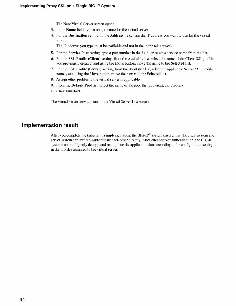
The New Virtual Server screen opens.3. In the Name field, type a unique name for the virtual server.4. For the Destination setting, in the Address field, type the IP address you want to use for the virtual
server.The IP address you type must be available and not in the loopback network.
5. For the Service Port setting, type a port number in the field, or select a service name from the list.6. For the SSL Profile (Client) setting, from the Available list, select the name of the Client SSL profile
you previously created, and using the Move button, move the name to the Selected list.7. For the SSL Profile (Server) setting, from the Available list, select the applicable Server SSL profile
names, and using the Move button, move the names to the Selected list.8. Assign other profiles to the virtual server if applicable.9. From the Default Pool list, select the name of the pool that you created previously.10. Click Finished.
The virtual server now appears in the Virtual Server List screen.
Implementation result
After you complete the tasks in this implementation, the BIG-IP® system ensures that the client system andserver system can initially authenticate each other directly. After client-server authentication, the BIG-IPsystem can intelligently decrypt and manipulate the application data according to the configuration settingsin the profiles assigned to the virtual server.
94
Implementing Proxy SSL on a Single BIG-IP System

Configuring HTTP Load Balancing with Source AddressAffinity Persistence
Overview: HTTP load balancing with source affinity persistence
Many computing environments want to use a BIG-IP® system to intelligently manage their HTTP traffic.You can easily control your HTTP traffic by implementing a BIG-IP system feature known as an HTTPprofile. An HTTP profile is a group of settings that affect the behavior of HTTP traffic. An HTTP profiledefines the way that you want the BIG-IP system to manage HTTP traffic.
You can use the default HTTP profile, with all of its default values, or you can create a customHTTP profile.This particular implementation uses the default HTTP profile.
When you configure the BIG-IP system to manage HTTP traffic, you can also implement simple sessionpersistence, also known as source address affinity persistence. Source address affinity persistence directssession requests to the same server based solely on the source IP address of a packet. To implement sourceaddress affinity persistence, the BIG-IP system offers a default persistence profile that you can implement.Just as for HTTP, you can use the default profile, or you can create a custom simple persistence profile.
Task summary
This implementation describes how to set up a basic HTTP load balancing scenario and source addressaffinity persistence, using the default HTTP and source address affinity persistence profiles.
Because this implementation configures HTTP load balancing and session persistence using the defaultHTTP and persistence profiles, you do not need to specifically configure these profiles. Instead, you simplyconfigure some settings on the virtual server when you create it.
Task listCreating a pool to manage HTTP trafficCreating a virtual server for HTTP traffic
Creating a pool to manage HTTP traffic
You can create a pool to manage HTTP connections.
1. On the Main tab, click Local Traffic > Pools.The Pool List screen opens.
2. Click Create.The New Pool screen opens.
3. In the Name field, type a unique name for the pool.4. For theHealth Monitors setting, from the Available list, select the httpmonitor, and click << to move
the monitor to the Active list.

5. From the Load Balancing Method list, select how the system distributes traffic to members of thispool.The default is Round Robin.
6. For the Priority Group Activation setting, specify how to handle priority groups:
• Select Disabled to disable priority groups. This is the default option.• Select Less than, and in the Available Members field, type the minimum number of members that
must remain available in each priority group in order for traffic to remain confined to that group.
7. Using the New Members setting, add each resource that you want to include in the pool:a) Type an IP address in the Address field, or select a node address from the Node List.b) Type 80 in the Service Port field, or select HTTP from the list.c) (Optional) Type a priority number in the Priority field.d) Click Add.
8. Click Finished.
The new pool appears in the Pools list.
Creating a virtual server for HTTP traffic
This task creates a destination IP address for application traffic. As part of this task, you must assign therelevant pool to the virtual server.
1. On the Main tab, click Local Traffic > Virtual Servers.The Virtual Server List screen displays a list of existing virtual servers.
2. Click the Create button.The New Virtual Server screen opens.
3. In the Name field, type a unique name for the virtual server.4. For the Destination setting, in the Address field, type the IP address you want to use for the virtual
server.The IP address you type must be available and not in the loopback network.
5. In the Service Port field, type 80, or select HTTP from the list.6. From the HTTP Profile list, select http.7. In the Resources area of the screen, from the Default Pool list, select a pool name.8. From the Default Persistence Profile list, select source_addr.
This implements simple persistence, using the default source address affinity profile.9. Click Finished.
You now have a virtual server to use as a destination address for application traffic.
96
Configuring HTTP Load Balancing with Source Address Affinity Persistence

Configuring HTTP Load Balancing with Cookie Persistence
Overview: HTTP load balancing with cookie persistence
Many computing environments want to use a BIG-IP® system to intelligently manage their HTTP traffic.You can easily control your HTTP traffic by implementing a BIG-IP system feature known as an HTTPprofile. An HTTP profile is a group of settings that affects the behavior of HTTP traffic. An HTTP profiledefines the way that you want the system to manage HTTP traffic.
You can use the default HTTP profile, with all of its default values, or you can create a customHTTP profile.When you create a custom HTTP profile, you not only modify the setting values, but you can enable moreadvanced features such as data compression of server responses.
When you configure the BIG-IP system to manage HTTP traffic, you can also implement cookie-basedsession persistence. Cookie persistence directs session requests to the same server based on HTTP cookiesthat the BIG-IP system stores in the client’s browser.
Task summary
This implementation describes how to set up a basic HTTP load balancing scenario and cookie persistence,using the default HTTP profile.
Because this implementation configures HTTP load balancing and session persistence using the defaultHTTP, you do not need to specifically configure this profile. Instead, you simply configure some settingson the virtual server when you create it.
Task listCreating a custom cookie persistence profileCreating a pool to manage HTTP trafficCreating a virtual server for HTTP traffic
Creating a custom cookie persistence profile
A good way to implement cookie persistence is to create a custom cookie persistence profile.
1. On the Main tab, click Local Traffic > Profiles > Persistence.The Persistence profile list screen opens.
2. Click Create.The New Persistence Profile screen opens.
3. In the Name field, type a name for the profile.4. From the Persistence Type list, select Cookie.5. From the Parent Profile list, select cookie.6. Select the Custom check box.
The fields in the Settings area become available for revision.

7. From the Cookie Method list, select HTTP Cookie Insert.8. Clear the Session Cookie check box.9. Type 60 in theMinutes field.10. Click Finished.
The custom cookie persistence profile appears in the Persistence list.
Creating a pool to manage HTTP traffic
You can create a pool to manage HTTP connections.
1. On the Main tab, click Local Traffic > Pools.The Pool List screen opens.
2. Click Create.The New Pool screen opens.
3. In the Name field, type a unique name for the pool.4. For theHealth Monitors setting, from the Available list, select the httpmonitor, and click << to move
the monitor to the Active list.5. From the Load Balancing Method list, select how the system distributes traffic to members of this
pool.The default is Round Robin.
6. For the Priority Group Activation setting, specify how to handle priority groups:
• Select Disabled to disable priority groups. This is the default option.• Select Less than, and in the Available Members field, type the minimum number of members that
must remain available in each priority group in order for traffic to remain confined to that group.
7. Using the New Members setting, add each resource that you want to include in the pool:a) Type an IP address in the Address field, or select a node address from the Node List.b) Type 80 in the Service Port field, or select HTTP from the list.c) (Optional) Type a priority number in the Priority field.d) Click Add.
8. Click Finished.
The new pool appears in the Pools list.
Creating a virtual server for HTTP traffic
This task creates a destination IP address for application traffic. As part of this task, you must assign therelevant pool to the virtual server.
Note: You can also use HTTP Cookie Insert persistence with a Performance (HTTP) type of virtual server.
1. On the Main tab, click Local Traffic > Virtual Servers.The Virtual Server List screen displays a list of existing virtual servers.
2. Click the Create button.The New Virtual Server screen opens.
3. In the Name field, type a unique name for the virtual server.
98
Configuring HTTP Load Balancing with Cookie Persistence

4. For the Destination setting, in the Address field, type the IP address you want to use for the virtualserver.The IP address you type must be available and not in the loopback network.
5. In the Service Port field, type 80, or select HTTP from the list.6. From the HTTP Profile list, select http.7. In the Resources area of the screen, from the Default Pool list, select a pool name.8. From the Default Persistence Profile list, select the name of the custom cookie profile you created
earlier, such as mycookie_profile.This implements cookie persistence, using a custom cookie persistence profile.
9. Click Finished.
You now have a virtual server to use as a destination address for application traffic.
99
BIG-IP® Local Traffic Manager™: Implementations


Compressing HTTP Responses
Overview: Compressing HTTP responses
An optional feature of the BIG-IP® system is the system’s ability to off-load HTTP compression tasks fromthe target server. All of the tasks that you need to configure HTTP compression, as well as the compressionsoftware itself, are centralized on the BIG-IP system. The primary way to enable HTTP compression is byconfiguring an HTTP Compression type of profile and then assigning the profile to a virtual server. Thiscauses the system to compress HTTP content for any responses matching the values that you specify in theRequest-URI or Content-Type settings of the HTTP Compression profile.
Tip: If you want to enable HTTP compression for specific connections, you can write an iRule that specifiesthe HTTP:compress enable command. Using the BIG-IP systemHTTP compression feature, you can includeor exclude certain types of URIs or files that you specify. This is useful because some URI or file types mightalready be compressed. F5 Networks does not recommend using CPU resources to compressalready-compressed data because the cost of compressing the data usually outweighs the benefits. Examplesof regular expressions that you might want to specify for exclusion are .*\.pdf, .*\.gif, or .*\.html.
Task summary
To configure HTTP data compression, you need to create an HTTP compression type of profile, as well asa virtual server.
Task listCreating a customized HTTP compression profileCreating a virtual server for HTTP compression
Creating a customized HTTP compression profile
If you need to adjust the compression settings to optimize compression for your environment, you canmodify a custom HTTP compression profile.
1. On the Main tab, click Local Traffic > Profiles > Services > HTTP Compression.The HTTP Compression profile list screen opens.
2. Click Create.The New HTTP Compression Profile screen opens.
3. In the Name field, type a name for the profile.4. From the Parent Profile list, select one of the following profiles:
• httpcompression.• wan-optimized-compression.
5. Select the Custom check box.

The fields in the Settings area become available for revision.6. Modify the settings, as required.7. Click Finished.
The modified HTTP compression profile is available in the HTTP Compression list screen.
Creating a virtual server for HTTP compression
You can create a virtual server that uses an HTTP profile with an HTTP compression profile to compressHTTP responses.
1. On the Main tab, click Local Traffic > Virtual Servers.The Virtual Server List screen displays a list of existing virtual servers.
2. Click the Create button.The New Virtual Server screen opens.
3. In the Name field, type a unique name for the virtual server.4. For the Destination setting, in the Address field, type the IP address you want to use for the virtual
server.The IP address you type must be available and not in the loopback network.
5. In the Service Port field, type 80, or select HTTP from the list.6. Select http in the HTTP Profile list.7. From the HTTP Compression Profile list, select one of the following profiles:
• httpcompression• wan-optimized-compression• A customized profile
8. In the Resources area of the screen, from the Default Pool list, select a pool name.9. Click Finished.
The virtual server with an HTTP profile configured with an HTTP compression profile appears in the VirtualServer list.
After you have created a customHTTPCompression profile and a virtual server, you can test the configurationby attempting to pass HTTP traffic through the virtual server. Check to see that the BIG-IP system includesand excludes the responses that you specified in the custom profile, and that the system compresses the dataas specified.
102
Compressing HTTP Responses

Using the Request Logging Profile
Overview: Configuring a request logging profile
The request logging profile gives you the ability to configure data within a log file for requests and responsesin accordance with specified parameters.
Task summary
Perform these tasks to log request and response data.Creating a pool with request logging to manage HTTP trafficCreating a request logging profileConfiguring a virtual server for request loggingDeleting a request logging profile
Creating a pool with request logging to manage HTTP traffic
For a basic configuration, you need to create a pool to manage HTTP connections.
1. On the Main tab, click Local Traffic > Pools.The Pool List screen opens.
2. Click Create.The New Pool screen opens.
3. In the Name field, type a unique name for the pool.4. For theHealth Monitors setting, from the Available list, select the httpmonitor, and click << to move
the monitor to the Active list.5. From the Load Balancing Method list, select how the system distributes traffic to members of this
pool.The default is Round Robin.
6. For the Priority Group Activation setting, specify how to handle priority groups:
• Select Disabled to disable priority groups. This is the default option.• Select Less than, and in the Available Members field, type the minimum number of members that
must remain available in each priority group in order for traffic to remain confined to that group.
7. Add the IP address for each logging server that you want to include in the pool, using theNewMemberssetting:a) Type an IP address in the Address, field or select a node address from the Node List.b) Type 80 in the Service Port field, or select HTTP from the list.c) (Optional) Type a priority number in the Priority field.d) Click Add.

8. Click Finished.
The new pool appears in the Pools list.
Creating a request logging profile
You must have already created a pool that includes logging servers as pool members before you can createa request logging profile.
With a request logging profile, you can log specified data for HTTP requests and responses, and then usethat information for analysis and troubleshooting.
1. On the Main tab, click Local Traffic > Profiles > Other > Request Logging.The Request Logging profile list screen opens.
2. Click Create.The New Request Logging Profile screen opens.
3. From the Parent Profile list, select a profile from which the new profile inherits properties.4. Above the Request Settings area, select the Custom check box.
This enables all settings in the Request Settings area, making them available for change.5. Configure the request settings, as necessary.6. Select the Custom check box for the Response Settings area.
The settings in the Response Settings area become available for configuring.7. Configure the response settings, as necessary.8. Click Finished.
This makes a request logging profile available to log specified data for HTTP requests and responses.
You must configure a virtual server for request logging.
Configuring a request logging profile for requests
Ensure that the configuration includes a pool that includes logging servers as pool members.
You can use a request logging profile to log specified data for HTTP requests, and then use that informationfor analysis and troubleshooting.
1. On the Main tab, click Local Traffic > Profiles > Other > Request Logging.The Request Logging profile list screen opens.
2. Click Create.The New Request Logging Profile screen opens.
3. From the Parent Profile list, select a profile from which the new profile inherits properties.4. Above the Request Settings area, select the Custom check box.
This enables all settings in the Request Settings area, making them available for change.5. From the Request Logging list, select Enabled.6. In the Template field, type the request logging parameters for the entries that you want to include in
the log file.7. From the HSL Protocol list, select a high-speed logging protocol.8. From the Pool Name list, select the pool that includes the logging server as a pool member.9. (Optional) You can also configure the error response settings.
a) From the Respond On Error list, select Enabled.
104
Using the Request Logging Profile

b) In the Error Response field, type the error response strings that you want to include in the log file.These strings must be well-formed for the protocol serving the strings.
c) Select the Close On Error check box to drop the request and close the connection if logging fails.
10. (Optional) You can also configure the logging request errors settings.a) From the Log Logging Errors list, select Enabled.b) In the Error Template field, type the request logging parameters for the entries that you want to
include in the log file.c) From the HSL Error Protocol list, select a high-speed logging error protocol.d) From the Error Pool Name list, select a pool that includes the node for the error logging server as
a pool member.
11. Click Update.
This configures a request logging profile to log specified data for HTTP requests.
Configuring a request logging profile for responses
Youmust have already created a pool that includes logging servers as pool members before you can configurea request logging profile for responses.
With a request logging profile, you can log specified data for HTTP requests and responses, and then usethat information for analysis and troubleshooting.
1. On the Main tab, click Local Traffic > Profiles > Other > Request Logging.The Request Logging profile list screen opens.
2. From the Parent Profile list, select a profile from which the new profile inherits properties.3. Select the Custom check box for the Response Settings area.
The settings in the Response Settings area become available for configuring.4. In the Response Settings area, from the Response Logging list, select Enabled.5. (Optional) Select the Log By Default check box.
The Log By Default check box is selected by default.
6. In the Template field, type the response logging parameters for the entries that you want to include inthe log file.
7. From the HSL Protocol list, select a high-speed logging protocol.8. From the Pool Name list, select the pool that includes the node logging server as a pool member.9. (Optional) Configure the logging request error settings.
a) From the Log Logging Errors list, select Enabled.b) In the Error Template field, type the response logging parameters for the entries that you want to
include in the log file.c) From the HSL Error Protocol list, select a high-speed logging error protocol.d) From the Error Pool Name list, select a pool that includes the node for the error logging server as
a pool member.
10. Click Update to save your changes.
This configures a request logging profile to log specified data for HTTP responses.
105
BIG-IP® Local Traffic Manager™: Implementations

Configuring a virtual server for request logging
You can configure a virtual server to pass traffic to logging servers.
1. On the Main tab, click Local Traffic > Virtual Servers.The Virtual Server List screen displays a list of existing virtual servers.
2. Click the name of the virtual server you want to modify.3. Click the Resources tab.4. From theDefault Pool list, select a pool name that is configured with pool members for request logging.5. Click the Properties tab.6. From the Configuration list, select Advanced.7. From the Request Logging Profile list, select the profile you want to assign to the virtual server.8. Click Update.
This virtual server can now pass traffic to the configured logging servers.
Deleting a request logging profile
You can delete a user-defined request logging profile that is obsolete or no longer needed.
1. On the Main tab, click Local Traffic > Profiles > Other > Request Logging.The Request Logging profile list screen opens.
2. Select the check box for the applicable profile.3. Click Delete.4. Click Delete.
The profile is deleted.
Request logging profile settings
With the request logging profile, you can specify the data and the format for HTTP requests and responsesthat you want to include in a log file.
General Properties
DescriptionValueSetting
No defaultName
Specifies the selected predefined oruser-defined profile.
Selected predefined or user-definedprofile
Parent Profile
Request Settings
DescriptionValueSetting
Enables logging for requests.DisabledRequest Logging
106
Using the Request Logging Profile

DescriptionValueSetting
Specifies the directives and entries to be logged.Template
Specifies the protocol to be used for high-speed logging ofrequests.
UDPHSL Protocol
Defines the pool associated with the virtual server that islogged.
NonePool Name
Enables the ability to respond when an error occurs.DisabledRespond On Error
Specifies the response text to be used when an error occurs.
For example, the following response text provides contentfor a 503 error.
<html>
NoneError Response
<head><title>ERROR</title></head><body><p>503 ERROR-Service Unavailable</p></body></html>
When enabled, and logging fails, drops the request andcloses the connection.
DisabledClose On Error
Enables the ability to log any errors when logging requests.DisabledLog Logging Errors
Defines the format for requests in an error log.NoneError Template
Defines the protocol to be used for high-speed logging ofrequest errors.
UDPHSL Error Protocol
Specifies the name of the error logging pool for requests.NoneError Pool Name
Response Settings
DescriptionValueSetting
Enables logging for responses.DisabledResponse Logging
Defines whether to log the specified settings forresponses by default.
EnabledLog By Default
Specifies the directives and entries to be logged.NoneTemplate
Specifies the protocol to be used for high-speed loggingof responses.
HSLHSL Protocol
Defines the pool name associated with the virtual serverthat is logged.
NonePool Name
Enables the ability to log any errors when loggingresponses.
DisabledLog Logging Errors
Defines the format for responses in an error log.NoneError Template
Defines the protocol to be used for high-speed loggingof response errors.
UDPHSL Error Protocol
107
BIG-IP® Local Traffic Manager™: Implementations
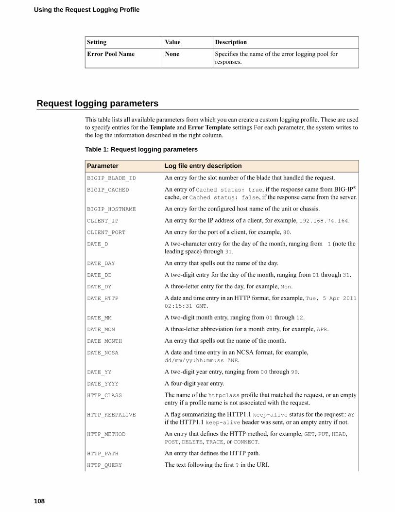
DescriptionValueSetting
Specifies the name of the error logging pool forresponses.
NoneError Pool Name
Request logging parameters
This table lists all available parameters from which you can create a custom logging profile. These are usedto specify entries for the Template and Error Template settings For each parameter, the system writes tothe log the information described in the right column.
Table 1: Request logging parameters
Log file entry descriptionParameter
An entry for the slot number of the blade that handled the request.BIGIP_BLADE_ID
An entry of Cached status: true, if the response came from BIG-IP®cache, or Cached status: false, if the response came from the server.
BIGIP_CACHED
An entry for the configured host name of the unit or chassis.BIGIP_HOSTNAME
An entry for the IP address of a client, for example, 192.168.74.164.CLIENT_IP
An entry for the port of a client, for example, 80.CLIENT_PORT
A two-character entry for the day of the month, ranging from 1 (note theleading space) through 31.
DATE_D
An entry that spells out the name of the day.DATE_DAY
A two-digit entry for the day of the month, ranging from 01 through 31.DATE_DD
A three-letter entry for the day, for example, Mon.DATE_DY
A date and time entry in an HTTP format, for example, Tue, 5 Apr 201102:15:31 GMT.
DATE_HTTP
A two-digit month entry, ranging from 01 through 12.DATE_MM
A three-letter abbreviation for a month entry, for example, APR.DATE_MON
An entry that spells out the name of the month.DATE_MONTH
A date and time entry in an NCSA format, for example,dd/mm/yy:hh:mm:ss ZNE.
DATE_NCSA
A two-digit year entry, ranging from 00 through 99.DATE_YY
A four-digit year entry.DATE_YYYY
The name of the httpclass profile that matched the request, or an emptyentry if a profile name is not associated with the request.
HTTP_CLASS
A flag summarizing the HTTP1.1 keep-alive status for the request:: aYif the HTTP1.1 keep-alive header was sent, or an empty entry if not.
HTTP_KEEPALIVE
An entry that defines the HTTP method, for example, GET, PUT, HEAD,POST, DELETE, TRACE, or CONNECT.
HTTP_METHOD
An entry that defines the HTTP path.HTTP_PATH
The text following the first ? in the URI.HTTP_QUERY
108
Using the Request Logging Profile

Log file entry descriptionParameter
The complete text of the request, for example, $METHOD $URI $VERSION.HTTP_REQUEST
The numerical response status code, that is, the status response codeexcluding subsequent text.
HTTP_STATCODE
The complete status response, that is, the number appended with anysubsequent text.
HTTP_STATUS
An entry for the URI of the request.HTTP_URI
An entry that defines the HTTP version.HTTP_VERSION
An NCSA Combined formatted log string, for example, $NCSA_COMMON$Referer ${User-agent} $Cookie.
NCSA_COMBINED
An NCSA Common formatted log string, for example, $CLIENT_IP - -$DATE_NCSA $HTTP_REQUEST $HTTP_STATCODE $RESPONSE_SIZE.
NCSA_COMMON
The elapsed time in milliseconds (ms) between receiving the request andsending the response.
RESPONSE_MSECS
An entry for the size of response in bytes.RESPONSE_SIZE
The elapsed time in microseconds (µs) between receiving the request andsending the response.
RESPONSE_USECS
An entry for the IP address of a server, for example, 10.10.0.1.SERVER_IP
An entry for the port of a server, for example, 80.SERVER_PORT
An entry for the self IP address of the BIG-IP-originated connection to theserver when SNAT is enabled, or an entry for the client IP address whenSNAT is not enabled.
SNAT_IP
An entry for the port of the BIG-IP-originated connection to the server whenSNAT is enabled, or an entry for the client port when SNAT is not enabled.
SNAT_PORT
A twelve-hour request-time qualifier, for example, AM or PM.TIME_AMPM
A compact twelve-hour time entry for request-time hours, ranging from 1through 12.
TIME_H12
A twelve-hour time entry for hours, for example, 12 AM.TIME_HRS
A twelve hour entry for request-time hours, ranging from 01 through 12.TIME_HH12
An entry for a compact request time of H:M:S, for example, 12:10:49.TIME_HMS
A twenty-four hour entry for request-time hours, ranging from 00 through23.
TIME_HH24
A two-digit entry for minutes, ranging from 00 through 59.TIME_MM
An entry for the request-time fraction in milliseconds (ms).TIME_MSECS
An entry for the time zone, offset in hours from GMT, for example, -11.TIME_OFFSET
A two-digit entry for seconds, ranging from 00 through 59.TIME_SS
A UNIX time entry for the number of seconds since the UNIX epoch, forexample, 00:00:00 UTC, January 1st, 1970.
TIME_UNIX
An entry for the request-time fraction in microseconds (µs).TIME_USECS
An entry for the current Olson database or tz database three-character timezone, for example, PDT.
TIME_ZONE
An entry for the IP address of a virtual server, for example, 192.168.10.1.VIRTUAL_IP
109
BIG-IP® Local Traffic Manager™: Implementations

Log file entry descriptionParameter
An entry for the name of a virtual server.VIRTUAL_NAME
An entry for the name of the pool containing the responding server.VIRTUAL_POOL_NAME
An entry for the port of a virtual server, for example, 80.VIRTUAL_PORT
The name of the Secure Network Address Translation pool associated withthe virtual server.
VIRTUAL_SNATPOOL_NAME
An entry that defines the name of the WebAccelerator™ application thatprocessed the request.
WAM_APPLICATION_NAM
An entry that specifies a diagnostic string (X-WA-Info header) used by theWebAccelerator system to process the request.
WAM_X_WA_INFO
Undelineated strings return the value of the respective header.NULL
110
Using the Request Logging Profile

Load Balancing Passive Mode FTP Traffic
Overview: FTP passive mode load balancing
You can set up the BIG-IP system to load balance passive mode FTP traffic. You do this by using the defaultFTP profile. An FTP profile determines the way that the BIG-IP system processes FTP traffic.
Additionally, you can create an iRule to apply to the FTP data channel. You apply the iRule to the datachannel by assigning the iRule to the virtual server that you create.
Task Summary for load balancing passive mode FTP traffic
You can perform these tasks to configure FTP passive mode load balancing.
Task listCreating a custom FTP monitorCreating a pool to manage FTP trafficCreating a virtual server for FTP traffic
Creating a custom FTP monitor
An FTP monitor requires a user name and password, and the full path to the file to be downloaded.
Create a custom FTP monitor to verify the File Transfer Protocol (FTP) service. The monitor attempts todownload a specified file to the /var/tmp directory. If the file is retrieved, the check is successful.
Note: The BIG-IP® system does not save the downloaded file.
Create a custom FTP monitor to verify passive mode File Transfer Protocol (FTP) traffic. The monitorattempts to download a specified file to the /var/tmp directory. If the file is retrieved, the check is successful.
Note: The BIG-IP® system does not save the downloaded file.
1. On the Main tab, click Global Traffic > Link Controller >Monitors.The Monitor List screen opens.
2. On the Main tab, click Local Traffic >Monitors.The Monitor List screen opens.
3. Click Create.The New Monitor screen opens.
4. Type a name for the monitor in the Name field.5. From the Type list, select FTP.
The screen refreshes, and displays the configuration options for the FTP monitor type.6. From the Import Settings list, select an existing monitor.

The new monitor inherits initial configuration values from the existing monitor.
7. Type a number in the Interval field that indicates, in seconds, how frequently the system issues themonitor check. The default is 10 seconds.The frequency of a monitor check must be greater than the value of the global-levelHeartbeat Intervalsetting. Otherwise, the monitor can acquire out-of-date data.
8. Type a number in the Timeout field that indicates, in seconds, how much time the target has to respondto the monitor check. The default is 31 seconds.If the target responds within the allotted time period, it is considered up. If the target does not respondwithin the time period, it is considered down.
9. Type a number in the Probe Timeout field that indicates the number of seconds after which the systemtimes out the probe request to the system. The default is 5 seconds.
10. Type a name in the User Name field.11. Type a password in the Password field.12. Type the full path and file name of the file that the system attempts to download in the Path/Filename
field.The health check is successful if the system can download the file.
13. For theMode setting, select one of the following data transfer process (DTP) modes.DescriptionOption
The monitor sends a data transfer request to the FTP server. When the FTPserver receives the request, the FTP server initiates and establishes the dataconnection.
Passive
The monitor initiates and establishes the data connection with the FTP server.Port
14. In the Configuration area of the screen, select Advanced.This selection makes it possible for you to modify additional default settings.
15. From the Up Interval list, do one of the following:
• Accept the default, Disabled, if you do not want to use the up interval.• Select Enabled, and specify how often you want the system to verify the health of a resource that
is up.
16. Type a number in the Time Until Up field that indicates the number of seconds to wait after a resourcefirst responds correctly to the monitor before setting the resource to up.The default value is 0 (zero), which disables this option.
17. Specify whether the system automatically enables the monitored resource, when the monitor check issuccessful, forManual Resume.This setting applies only when the monitored resource has failed to respond to a monitor check.
DescriptionOptionThe system does nothing when themonitor check succeeds, and youmust manuallyenable the monitored resource.
Yes
The system automatically re-enables the monitored resource after the nextsuccessful monitor check.
No
18. For the Alias Address setting, do one of the following:
• Accept the *All Addresses default option.• Type an alias IP address for the monitor to verify, on behalf of the pools or pool members with which
the monitor is associated.
112
Load Balancing Passive Mode FTP Traffic

If the health check for the alias address is successful, the system marks all associated objects up. If thehealth check for the alias address is not successful, then the system marks all associated objects down.
19. For the Alias Service Port setting, do one of the following:
• Accept the *All Ports default option.• Select an alias port or service for the monitor to check, on behalf of the pools or pool members with
which the monitor is associated.
If the health check for the alias port or service is successful, the system marks all associated objects up.If the health check for the alias port or service is not successful, then the system marks all associatedobjects down.
20. For theDebug setting, specify whether you want the system to collect and publish additional informationand error messages for this monitor.You can use the log information to help diagnose and troubleshoot unsuccessful health checks. To viewthe log entries, see the System > Logs screens.
DescriptionOptionThe system redirects error messages and other information to a log file createdspecifically for this monitor.
Yes
The system does not collect additional information or error messages related tothis monitor. This is the default setting.
No
21. Click Finished.
You can associate the new custom monitor with the server, virtual server, or pool member that contains theFTP resources.You can associate the new custom monitor with the pool that contains the FTP resources.
Creating a pool to manage FTP traffic
To load balance passive mode FTP traffic, you create a load balancing pool. When you create the pool, youassign the custom FTP monitor that you created in the previous task.
1. On the Main tab, click Local Traffic > Pools.The Pool List screen opens.
2. Click Create.The New Pool screen opens.
3. In the Name field, type a unique name for the pool.4. For the Health Monitors setting, in the Available list, select a monitor type, and click << to move the
monitor to the Active list.
Tip: Hold the Shift or Ctrl key to select more than one monitor at a time.
5. From the Priority Group Activation list, select Disabled.6. Add each resource that you want to include in the pool using the New Members setting:
a) Type an IP address in the Address field, or select a node address from the Node List.b) Type 21 in the Service Port field, or select FTP from the list.c) (Optional) Type a priority number in the Priority field.d) Click Add.
7. Click Finished.
113
BIG-IP® Local Traffic Manager™: Implementations

The pool to manage FTP traffic appears in the Pools list.
Creating a virtual server for FTP traffic
You can define a virtual server that references the FTP profile and the FTP pool.
1. On the Main tab, click Local Traffic > Virtual Servers.The Virtual Server List screen displays a list of existing virtual servers.
2. Click the Create button.The New Virtual Server screen opens.
3. In the Name field, type a unique name for the virtual server.4. For the Destination setting, in the Address field, type the IP address you want to use for the virtual
server.The IP address you type must be available and not in the loopback network.
5. In the Service Port field, type 21 or select FTP from the list.6. For the FTP Profile setting, select the default profile, ftp.7. Locate the Resources area of the screen, and for the Related iRules setting, from the Available list,
select the name of the iRule that you want to assign, and using the Move button, move the name to theEnabled list.This setting applies to virtual servers that reference a profile for a data channel protocol, such as FTPor RTSP.
8. In the Resources area of the screen, from the Default Pool list, select a pool name.9. Click Finished.
The custom FTP virtual server appears in the Virtual Servers list.
114
Load Balancing Passive Mode FTP Traffic

Load Balancing Passive Mode FTP Traffic with Data ChannelOptimization
Overview: FTP passive mode load balancing with data channel optimization
You can set up the BIG-IP system to load balance passive mode FTP traffic, with optimization of both theFTP control channel and the data channel.
By default, the BIG-IP system optimizes FTP traffic for the control channel, according to the configurationsettings in the default client and server TCP profiles assigned to the virtual server. When you use thisparticular implementation, you also configure the system to take advantage of those same TCP profilesettings for the FTP data channel. This provides useful optimization of the data channel payload.
Task Summary for load balancing passive mode FTP traffic
You can perform these tasks to configure FTP passive mode load balancing that optimizes traffic on boththe control channel and data channel.
Task listCreating a custom FTP profileCreating a custom FTP monitorCreating a pool to manage FTP trafficCreating a virtual server for FTP traffic
Creating a custom FTP profile
You create a custom FTP profile when you want to fine-tune the way that the BIG-IP®system manages FTPtraffic. This procedure creates an FTP profile and optimizes the way that the BIG-IP systemmanages trafficfor the FTP data channel.
1. On the Main tab, click Local Traffic > Profiles > Services > FTP.The FTP profile list screen opens.
2. Click Create.The New FTP Profile screen opens.
3. In the Name field, type a name for the profile.4. From the Parent Profile list, select the default ftp profile.5. On the right side of the screen, select the Custom check box.
The settings in the Settings area become available for modification.6. For the Inherit Parent Profile setting, select the check box.
This optimizes data channel traffic.7. Click Finished.

The custom FTP profile now appears in the FTP profile list screen.
Creating a custom FTP monitor
An FTP monitor requires a user name and password, and the full path to the file to be downloaded.
Create a custom FTP monitor to verify passive mode File Transfer Protocol (FTP) traffic. The monitorattempts to download a specified file to the /var/tmp directory. If the file is retrieved, the check is successful.
Note: The BIG-IP® system does not save the downloaded file.
1. On the Main tab, click Local Traffic >Monitors.The Monitor List screen opens.
2. Click Create.The New Monitor screen opens.
3. Type a name for the monitor in the Name field.4. From the Type list, select FTP.
The screen refreshes, and displays the configuration options for the FTP monitor type.5. From the Import Settings list, select an existing monitor.
The new monitor inherits initial configuration values from the existing monitor.
6. Type a number in the Interval field that indicates, in seconds, how frequently the system issues themonitor check. The default is 10 seconds.The frequency of a monitor check must be greater than the value of the global-levelHeartbeat Intervalsetting. Otherwise, the monitor can acquire out-of-date data.
7. Type a number in the Timeout field that indicates, in seconds, how much time the target has to respondto the monitor check. The default is 31 seconds.If the target responds within the allotted time period, it is considered up. If the target does not respondwithin the time period, it is considered down.
8. Type a number in the Probe Timeout field that indicates the number of seconds after which the systemtimes out the probe request to the system. The default is 5 seconds.
9. Type a name in the User Name field.10. Type a password in the Password field.11. Type the full path and file name of the file that the system attempts to download in the Path/Filename
field.The health check is successful if the system can download the file.
12. For theMode setting, select one of the following data transfer process (DTP) modes.DescriptionOption
The monitor sends a data transfer request to the FTP server. When the FTPserver receives the request, the FTP server initiates and establishes the dataconnection.
Passive
The monitor initiates and establishes the data connection with the FTP server.Port
13. In the Configuration area of the screen, select Advanced.This selection makes it possible for you to modify additional default settings.
14. From the Up Interval list, do one of the following:
• Accept the default, Disabled, if you do not want to use the up interval.
116
Load Balancing Passive Mode FTP Traffic with Data Channel Optimization

• Select Enabled, and specify how often you want the system to verify the health of a resource thatis up.
15. Type a number in the Time Until Up field that indicates the number of seconds to wait after a resourcefirst responds correctly to the monitor before setting the resource to up.The default value is 0 (zero), which disables this option.
16. Specify whether the system automatically enables the monitored resource, when the monitor check issuccessful, forManual Resume.This setting applies only when the monitored resource has failed to respond to a monitor check.
DescriptionOptionThe system does nothing when themonitor check succeeds, and youmust manuallyenable the monitored resource.
Yes
The system automatically re-enables the monitored resource after the nextsuccessful monitor check.
No
17. For the Alias Address setting, do one of the following:
• Accept the *All Addresses default option.• Type an alias IP address for the monitor to verify, on behalf of the pools or pool members with which
the monitor is associated.
If the health check for the alias address is successful, the system marks all associated objects up. If thehealth check for the alias address is not successful, then the system marks all associated objects down.
18. For the Alias Service Port setting, do one of the following:
• Accept the *All Ports default option.• Select an alias port or service for the monitor to check, on behalf of the pools or pool members with
which the monitor is associated.
If the health check for the alias port or service is successful, the system marks all associated objects up.If the health check for the alias port or service is not successful, then the system marks all associatedobjects down.
19. For theDebug setting, specify whether you want the system to collect and publish additional informationand error messages for this monitor.You can use the log information to help diagnose and troubleshoot unsuccessful health checks. To viewthe log entries, see the System > Logs screens.
DescriptionOptionThe system redirects error messages and other information to a log file createdspecifically for this monitor.
Yes
The system does not collect additional information or error messages related tothis monitor. This is the default setting.
No
20. Click Finished.
You can associate the new custom monitor with the pool that contains the FTP resources.
Creating a pool to manage FTP traffic
To load balance passive mode FTP traffic, you create a load balancing pool. When you create the pool, youassign the custom FTP monitor that you created in the previous task.
117
BIG-IP® Local Traffic Manager™: Implementations

1. On the Main tab, click Local Traffic > Pools.The Pool List screen opens.
2. Click Create.The New Pool screen opens.
3. In the Name field, type a unique name for the pool.4. For the Health Monitors setting, in the Available list, select a monitor type, and click << to move the
monitor to the Active list.
Tip: Hold the Shift or Ctrl key to select more than one monitor at a time.
5. From the Priority Group Activation list, select Disabled.6. Add each resource that you want to include in the pool using the New Members setting:
a) Type an IP address in the Address field, or select a node address from the Node List.b) Type 21 in the Service Port field, or select FTP from the list.c) (Optional) Type a priority number in the Priority field.d) Click Add.
7. Click Finished.
The pool to manage FTP traffic appears in the Pools list.
Creating a virtual server for FTP traffic
You can define a virtual server that references the FTP profile and the FTP pool.
1. On the Main tab, click Local Traffic > Virtual Servers.The Virtual Server List screen displays a list of existing virtual servers.
2. Click the Create button.The New Virtual Server screen opens.
3. In the Name field, type a unique name for the virtual server.4. For the Destination setting, in the Address field, type the IP address you want to use for the virtual
server.The IP address you type must be available and not in the loopback network.
5. In the Service Port field, type 21 or select FTP from the list.6. From the FTP Profile list, select the custom profile that you created earlier.7. Locate the Resources area of the screen, and for the Related iRules setting, from the Available list,
select the name of the iRule that you want to assign, and using the Move button, move the name to theEnabled list.This setting applies to virtual servers that reference a profile for a data channel protocol, such as FTPor RTSP.
8. In the Resources area of the screen, from the Default Pool list, select a pool name.9. Click Finished.
The custom FTP virtual server appears in the Virtual Servers list.
118
Load Balancing Passive Mode FTP Traffic with Data Channel Optimization

Implementation result
A BIG-IP system with this configuration can process FTP traffic in passive mode, in a way that optimizesthe traffic on both the control channel and the data channel. This optimization is based on the settings ofthe default client-side and server-side TCP profiles.
119
BIG-IP® Local Traffic Manager™: Implementations


Referencing an External File from within an iRule
Overview: Referencing an external file from an iRule
Using the BIG-IP® Configuration utility or tmsh, you can import a file or URL from another system to theBIG-IP system, with content that you want an iRule to return to a client, based on some iRule event. Possibleuses for this feature are:
• To send a web page other than the page that the client requested. For example, you might want thesystem to send a maintenance page instead of the requested page.
• To send an image.• To use a file as a template and modify the file in the iRule before sending the file.• To download policy information from an external server and merge that data with a locally-stored policy.
The file that an iRule accesses is known as an iFile, and can be any type of file, such as a binary file or atext file. These files are read-only files.
This example shows an iRule that references an iFile named ifileURL, in partition Common:
ltm rule ifile_rule {when HTTP_RESPONSE {# return a list of iFiles in all partitionsset listifiles [ifile listall]log local0. "list of ifiles: $listifiles"
# return the attributes of an iFile specifiedarray set array_attributes [ifile attributes "/Common/ifileURL"]foreach {array attr} [array get array_attributes ] {log local0. "$array : $attr"}
# serve an iFile when http status is 404.set file [ifile get "Common/ifileURL"]log local0. "file: $ifile"if { [HTTP::status] equals "404" } {HTTP:Respond 200 ifile "/Common/ifileURL"
}}}
iRule commands for iFiles
This list shows the commands available for referencing an iFile within an iRule. All of these commandsreturn a string, except for the command [ifile attributes IFILENAME], which returns an array.
[ifile get IFILENAME][ifile listall][ifile attributes IFILENAME][ifile size IFILENAME]

[ifile last_updated_by IFILENAME][ifile last_update_time IFILENAME][ifile revision IFILENAME][ifile checksum IFILENAME][ifile attributes IFILENAME]
Task summary
You can import an existing file to the BIG-IP® system, create an iFile that is based on the imported file,and then write an iRule that returns the content of that file to a client system, based on an iRule event.
Task listImporting a file to the BIG-IP systemCreating an iFileWriting an iRule that references an iFile
Importing a file to the BIG-IP system
As a prerequisite, the file you want to import must reside on the BIG-IP® system you specify.
You can import a file from another system onto the BIG-IP system, as the first step in writing an iRule thatreferences that file.
1. On the Main tab, click System > File Management > iFile List > Import.2. For the File Name setting, click Choose File.
The system opens a browse window so you can locate the file that you want to import to the BIG-IPsystem.
3. Browse for the file and click Open.The name of the file you select appears in the File Name setting.
4. In the Name field, type a new name for the file, such as 1k.html.The new file name appears in the list of imported files.
The result of this task is that the file you selected now resides on the BIG-IP system.
Creating an iFile
As a prerequisite, ensure that the current administrative partition is set to the partition in which you wantthe iFile to reside.
You perform this task to create an iFile that you can then reference in an iRule.
1. On the Main tab, click Local Traffic > iRules > iFile List.2. Click Create.3. In the Name field, type a new name for the iFile, such as ifileURL.4. From the File Name list, select the name of the imported file object, such as 1k.html.5. Click Finished.
The new iFile appears in the list of iFiles.
122
Referencing an External File from within an iRule

The result of this task is that you now have a file that an iRule can reference.
Writing an iRule that references an iFile
You perform this task to create an iRule that references an iFile.
Note: If the iFile resides in partition /Common, then specifying the partition when referencing the iFile isoptional. If the iFile resides in a partition other than /Common, such as /Partition_A, you must includethe partition name in the iFile path name within the iRule.
1. On the Main tab, click Local Traffic > iRules.The iRule List screen opens, displaying any existing iRules.
2. Click Create.The New iRule screen opens.
3. In the Name field, type a name between 1 and 31 characters, such as my_iRule.4. In the Definition field, type the syntax for the iRule using Tool Command Language (Tcl) syntax.
For complete and detailed information iRules syntax, see the F5 Networks DevCentral web site(http://devcentral.f5.com).
5. Click Finished.The new iRule appears in the list of iRules on the system.
Implementation result
You now have an iRule that accesses a file on the BIG-IP® system, based on a particular iRule event.
123
BIG-IP® Local Traffic Manager™: Implementations


Configuring the BIG-IP System as a DHCP Relay Agent
Overview: Managing IP addresses for DHCP clients
When you want to manage Dynamic Host Configuration Protocol (DHCP) client IP addresses, you canconfigure the BIG-IP® system to act as a DHCP relay agent. A common reason to configure the BIG-IPsystem as a DHCP relay agent is when the DHCP clients reside on a different subnet than the subnet of theDHCP servers.
About the BIG-IP system as a DHCP relay agent
ABIG-IP® virtual server, configured as a Dynamic Host Configuration Protocol (DHCP) relay type, providesyou with the ability to relay DHCP client requests for an IP address to one or more DHCP servers, availableas pool members in a DHCP pool, on different +virtual local area networks (VLANs). The DHCP clientrequest is relayed to all pool members, and the replies from all pool members are relayed back to the client.
Figure 9: A sample DHCP relay agent configuration
For example, a DHCP client sends a broadcast message to the destination IP address 255.255.255.255,which is the destination address configured on the virtual server. A DHCP relay type virtual serverautomatically uses port 67 for an IPv4 broadcast message or port 547 for an IPv6 broadcast message. TheBIG-IP virtual server receives this message on the VLAN with self IP address 10.20.0.1 and relays theDHCP request to all DHCP servers: 10.10.0.3 and 10.10.0.7.
All DHCP servers provide a DHCP response with available IP addresses to the BIG-IP virtual server, whichthen relays all responses to the client. The client accepts and uses only one of the IP addresses received.
Note: In this example, there is no hop between the DHCP client and the BIG-IP relay agent. However, acommon topology is one that includes this hop, which is often another BIG-IP system.
Alternate configuration
If the DHCP client subnet includes a BIG-IP system that serves as a hop to the BIG-IP relay agent, youmust perform two additional configuration tasks:
• You must configure the BIG-IP relay agent to relay the client DHCP requests to the DHCP serverswithout losing the originating subnet (source) IP address. This originating source IP address is typicallya self IP address of the BIG-IP system that resides on the client subnet. You configure the BIG-IP relayagent to preserve the originating source IP address by creating a SNAT that specifies the originatingself IP address as both the origin address and the translation address. A SNAT configured in this wayprevents the BIG-IP relay agent, before sending the DHCP broadcast message to the DHCP servers,from translating the source IP address of the incoming DHCP request to a different address.
• You must add a route (to the BIG-IP relay agent) that specifies the originating source IP address as thedestination for DHCP responses. The DHCP servers use this route to send their responses back throughthe BIG-IP relay agent to the clients.
Task summary
You configure the BIG-IP system to act as a Dynamic Host Configuration Protocol (DHCP) relay agent bycreating a pool of DHCP servers and then creating a virtual server to manage DHCP client broadcastmessages.
Task listCreating a pool of DHCP serversCreating a DHCP Relay type virtual server
Creating a pool of DHCP servers
Youmust create a pool that includes Dynamic Host Configuration Protocol (DHCP) servers as pool membersbefore you create a DHCP relay type virtual server.
1. On the Main tab, click Local Traffic > Pools.The Pool List screen opens.
2. Click Create.The New Pool screen opens.
3. In the Name field, type a unique name for the pool.4. (Optional) Type a description for the pool.5. (Optional) For the Health Monitors setting, in the Available list, select UDP, and click << to move
the monitor to the Active list.6. From the Load Balancing Method list, select a method.
Note: A DHCP pool requires a load balancing method, although actual load balancing across DHCPpool members is ignored and DHCP requests are sent to all DHCP pool members.
7. For the Priority Group Activation setting, select Disabled.8. Add each resource that you want to include in the pool using the New Members setting:
a) (Optional) Type a name in the Node Name field, or select a node address from the Node List.
a) Type an IP address in the Address field, or select a node address from the Node List.b) Type 67 (IPv4) or 547 (IPv6) in the Service Port field.c) Click Add.
9. Click Finished.
126
Configuring the BIG-IP System as a DHCP Relay Agent

A pool that includes DHCP servers as pool members is created.
Creating a DHCP Relay type virtual server
A DHCP relay type BIG-IP® virtual server provides you with the ability to relay DHCP client requests foran IP address to one or more DHCP servers, and provide DHCP server responses with an available IPaddress for the client.
1. On the Main tab, click Local Traffic > Virtual Servers.The Virtual Server List screen displays a list of existing virtual servers.
2. Click the Create button.The New Virtual Server screen opens.
3. In the Name field, type a unique name for the virtual server.4. (Optional) Type a description for the virtual server.5. From the Type list, select DHCP Relay.6. Select one of the following to configure a Destination type.
Steps to configureDestination
None.255.255.255.255 (IPv4 Default)
None.ff02::1:2 (IPv6 Default)
Select and configure one of the following types.Other
• Host, and type 255.255.255.255 in the Address field.• Network, type 255.255.255.255 in theAddress field, and
type 255.255.255.255 in theMask field.
7. From the State list, select Enabled.8. In the Configuration area for the VLAN and Tunnel Traffic setting, select the VLANs on the same
network as the DHCP clients to ensure that the BIG-IP system can accept the broadcast traffic from theclient.
9. From the Default Pool list, select the pool that is configured for DHCP servers.10. Click Finished.
A DHCP relay type virtual server is configured to provide the ability to relay DHCP client requests for anIP address to one or more DHCP servers, and provide DHCP server responses with an available IP addressfor the client.
Implementation result
The BIG-IP® system is configured to manage Dynamic Host Configuration Protocol (DHCP) client IPaddresses, using a DHCP Relay type virtual server to manage DHCP client broadcast messages.
127
BIG-IP® Local Traffic Manager™: Implementations


Configuring the BIG-IP System for DHCP Renewal
Overview: Renewing IP addresses for DHCP clients
You can configure the BIG-IP® system to manage DHCP renewal requests and responses.
About DHCP renewal
You can configure the BIG-IP system to act as a DHCP renewal system. A common reason to configurethe BIG-IP system as a renewal system is when the DHCP servers reside on a different subnet than that ofthe client systems, and the BIG-IP system is also configured as a DHCP relay agent. As a DHCP renewalsystem, the BIG-IP systemmanages the renewal of client IP addresses by DHCP servers before the addressesexpire.
During the renewal process, a DHCP client sends a renewal request, which is passed through a BIG-IPForwarding IP type of virtual server directly to the specific DHCP server that issued the initial client IPaddress. The DHCP server then sends a response to renew the lease for the client's IP address.
In the example shown in the illustration, a DHCP client sends a renewal message to the same BIG-IP systemthat initially acted as the DHCP relay agent. This renewal request is forwarded through a BIG-IP renewalvirtual server directly to DHCP server 1. DHCP server 1 then provides a response to renew the lease forthe client's IP address.
Figure 10: A sample DHCP renewal system configuration
Task summary
You configure a BIG-IP system to act as a Dynamic Host Configuration Protocol (DHCP) relay system bycreating a virtual server that specifically forwards DHCP renewal requests to the appropriate DHCP server.

Task listCreating a DHCP renewal virtual server
Creating a DHCP renewal virtual server
ADynamic Host Configuration Protocol (DHCP) renewal virtual server forwards a DHCP request messagefrom a DHCP client directly to a DHCP server, to automatically renew an IP address before it expires.
1. On the Main tab, click Local Traffic > Virtual Servers.The Virtual Server List screen displays a list of existing virtual servers.
2. Click the Create button.The New Virtual Server screen opens.
3. In the Name field, type a unique name for the virtual server.4. (Optional) Type a description for the virtual server.5. From the Type list, select Forwarding (IP).6. For a Destination type, select Host, and type the DHCP server IP address in the Address field.
Tip: If you have multiple DHCP servers, type 0.0.0.0 in the Address field.
7. In the Service Port field, type 67 (IPv4) or 547 (IPv6).8. From the Protocol list, select UDP.9. From the VLAN and Tunnel Traffic list, select the VLANs on the same network as the DHCP clients.10. Click Finished.
The BIG-IP system is now configured with a virtual server that can forward DHCP renewal requests directlyto the appropriate DHCP server.
Implementation result
The BIG-IP® system is configured to forward DHCP client renewal requests to appropriate DHCP serversthat reside on a different subnet than the client systems. The BIG-IP also forwards the DHCP server responsesback to the client systems, therefore ensuring that client IP addresses do not expire.
130
Configuring the BIG-IP System for DHCP Renewal
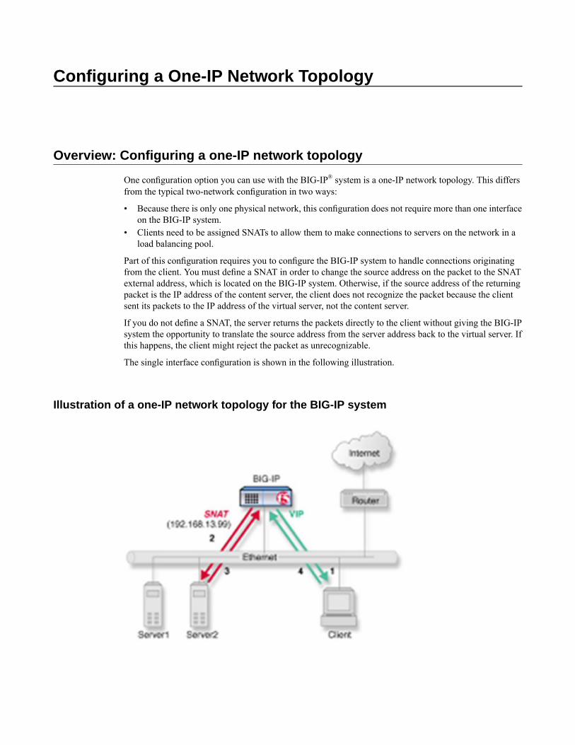
Configuring a One-IP Network Topology
Overview: Configuring a one-IP network topology
One configuration option you can use with the BIG-IP® system is a one-IP network topology. This differsfrom the typical two-network configuration in two ways:
• Because there is only one physical network, this configuration does not require more than one interfaceon the BIG-IP system.
• Clients need to be assigned SNATs to allow them to make connections to servers on the network in aload balancing pool.
Part of this configuration requires you to configure the BIG-IP system to handle connections originatingfrom the client. You must define a SNAT in order to change the source address on the packet to the SNATexternal address, which is located on the BIG-IP system. Otherwise, if the source address of the returningpacket is the IP address of the content server, the client does not recognize the packet because the clientsent its packets to the IP address of the virtual server, not the content server.
If you do not define a SNAT, the server returns the packets directly to the client without giving the BIG-IPsystem the opportunity to translate the source address from the server address back to the virtual server. Ifthis happens, the client might reject the packet as unrecognizable.
The single interface configuration is shown in the following illustration.
Illustration of a one-IP network topology for the BIG-IP system

Task summary for a one-IP network topology for the BIG-IP system
You can perform these tasks to configure a one-IP network topology.
Task listCreating a pool for processing HTTP connections with SNATs enabledCreating a virtual server for HTTP trafficDefining a default routeConfiguring a client SNAT
Creating a pool for processing HTTP connections with SNATs enabled
Verify that all content servers for the pool are in the network of VLAN external.
For a basic configuration, you need to create a pool to manage HTTP connections. This pool enables SNATsfor any connections destined for a member of the pool.
1. On the Main tab, click Local Traffic > Pools.The Pool List screen opens.
2. Click Create.The New Pool screen opens.
3. In the Name field, type a unique name for the pool.4. For theHealth Monitors setting, from the Available list, select the httpmonitor, and click << to move
the monitor to the Active list.5. For the Allow SNAT setting, verify that the value is Yes.6. In the Resources area of the screen, use the default values for theLoad BalancingMethod and Priority
Group Activation settings.7. Using the New Members setting, add each resource that you want to include in the pool:
a) Type an IP address in the Address field, or select a node address from the Node List.b) Type 80 in the Service Port field, or select HTTP from the list.c) (Optional) Type a priority number in the Priority field.d) Click Add.
8. Click Finished.
The new pool appears in the Pools list.
Creating a virtual server for HTTP traffic
This task creates a destination IP address for application traffic. As part of this task, you must assign therelevant pool to the virtual server.
1. On the Main tab, click Local Traffic > Virtual Servers.The Virtual Server List screen displays a list of existing virtual servers.
2. Click the Create button.The New Virtual Server screen opens.
3. In the Name field, type a unique name for the virtual server.
132
Configuring a One-IP Network Topology

4. For the Destination setting, in the Address field, type the IP address you want to use for the virtualserver.The IP address you type must be available and not in the loopback network.
5. In the Service Port field, type 80, or select HTTP from the list.6. From the HTTP Profile list, select http.7. In the Resources area of the screen, from the Default Pool list, select a pool name.8. Click Finished.
You now have a virtual server to use as a destination address for application traffic.
Defining a default route
Another task that you must perform to implement one-IP network load balancing is to define a default routefor the VLAN external.
1. On the Main tab, click Network > Routes.2. Click Add.
The New Route screen opens.3. From the Type list, select Default IPv4 Gateway.4. From the Resource list, select Use VLAN.
A VLAN represents the VLAN through which the packets flow to reach the specified destination.
5. Select external from the VLAN list.6. At the bottom of the screen, click Finished.
The default route for the VLAN external is defined.
Configuring a client SNAT
To configure the BIG-IP® system to handle connections originating from the client, you can define a SNATto change the source address on the packet to the SNAT external address located on the BIG-IP system.
1. On the Main tab, click Local Traffic > SNATs.The SNAT List screen displays a list of existing SNATs.
2. Click Create.3. Name the new SNAT.4. In the Translation field, type the IP address that you want to use as a translation IP address.5. From the Origin list, select Address List.6. For each client to which you want to assign a translation address, do the following:
a) Select Host.b) Type a client IP address in the Address field.c) Click Add.
7. From the VLAN Traffic list, select Enabled on.8. For the VLAN List setting, in the Available field, select external, and using theMove button, move
the VLAN name to the Selected field.9. Click Finished.
133
BIG-IP® Local Traffic Manager™: Implementations

The BIG-IP system is configured to handle connections originating from the client
134
Configuring a One-IP Network Topology

Implementing Health and Performance Monitoring
Overview: Health and performance monitoring
You can set up the BIG-IP® system to monitor the health or performance of certain nodes or servers thatare members of a load balancing pool. Monitors verify connections on pool members and nodes. A monitorcan be either a health monitor or a performance monitor, designed to check the status of a pool, pool member,or node on an ongoing basis, at a set interval. If a pool member or node being checked does not respondwithin a specified timeout period, or the status of a pool member or node indicates that performance isdegraded, the BIG-IP system can redirect the traffic to another pool member or node.
Some monitors are included as part of the BIG-IP system, while other monitors are user-created. Monitorsthat the BIG-IP system provides are called pre-configuredmonitors. User-createdmonitors are called custommonitors.
Before configuring and using monitors, it is helpful to understand some basic concepts regarding monitortypes, monitor settings, and monitor implementation.
Monitor typesEvery monitor, whether pre-configured or custom, is a certain type of monitor. Each type of monitorchecks the status of a particular protocol, service, or application. For example, one type of monitor isHTTP. An HTTP type of monitor allows you to monitor the availability of the HTTP service on a pool,pool member, or node. A WMI type of monitor allows you to monitor the performance of a pool, poolmember, or node that is running theWindowsManagement Instrumentation (WMI) software. An ICMPtype of monitor simply determines whether the status of a node is up or down.
Monitor settingsEvery monitor consists of settings with values. The settings and their values differ depending on thetype of monitor. In some cases, the BIG-IP system assigns default values. For example, the followingshows the settings and default values of an ICMP-type monitor.
Name my_icmpType ICMPInterval 5Timeout 16Transparent NoAlias Address * All Addresses
Note: If you want to monitor the performance of a RealNetworks® RealServer server or a Windows®-basedserver equipped with Windows Management Instrumentation (WMI), you must first download a specialplug-in file onto the BIG-IP system.
Task summary
To implement a health or performance monitor, you perform these tasks.

Task listCreating a custom monitorCreating a load balancing poolCreating a virtual server
Creating a custom monitor
Before creating a custom monitor, you must decide on a monitor type.
You can create a custom monitor when the values defined in a pre-configured monitor do not meet yourneeds, or no pre-configured monitor exists for the type of monitor you are creating.
Important: When defining values for custom monitors, make sure you avoid using any values that are onthe list of reserved keywords.
1. On the Main tab, click Local Traffic >Monitors.The Monitor List screen opens.
2. Click Create.The New Monitor screen opens.
3. Type a name for the monitor in the Name field.4. From the Type list, select the type of monitor.
The screen refreshes, and displays the configuration options for the monitor type.5. From the Import Settings list, select an existing monitor.
The new monitor inherits initial configuration values from the existing monitor.
6. In the Configuration area of the screen, select Advanced.This selection makes it possible for you to modify additional default settings.
7. Configure all settings shown.8. Click Finished.
Creating a load balancing pool
You can create a load balancing pool (a logical set of devices such as web servers that you group togetherto receive and process traffic) to efficiently distribute the load on your server resources.
Note: You must create the pool before you create the corresponding virtual server.
1. On the Main tab, click Local Traffic > Pools.The Pool List screen opens.
2. Click Create.The New Pool screen opens.
3. In the Name field, type a unique name for the pool.4. For the Health Monitors setting, in the Available list, select a monitor type, and click << to move the
monitor to the Active list.
Tip: Hold the Shift or Ctrl key to select more than one monitor at a time.
5. From the Load Balancing Method list, select how the system distributes traffic to members of thispool.
136
Implementing Health and Performance Monitoring

The default is Round Robin.
6. For the Priority Group Activation setting, specify how to handle priority groups:
• Select Disabled to disable priority groups. This is the default option.• Select Less than, and in the Available Members field, type the minimum number of members that
must remain available in each priority group in order for traffic to remain confined to that group.
7. Using the New Members setting, add each resource that you want to include in the pool:a) Either type an IP address in the Address field, or select a node address from the Node List.b) Type a port number in the Service Port field, or select a service name from the list.c) To specify a priority group, type a priority number in the Priority field.d) Click Add.
8. Click Finished.
The load balancing pool appears in the Pools list.
Creating a virtual server
A virtual server represents a destination IP address for application traffic.
1. On the Main tab, click Local Traffic > Virtual Servers.The Virtual Server List screen displays a list of existing virtual servers.
2. Click the Create button.The New Virtual Server screen opens.
3. In the Name field, type a unique name for the virtual server.4. For the Destination setting, in the Address field, type the IP address you want to use for the virtual
server.The IP address you type must be available and not in the loopback network.
5. For the Service Port setting, type a port number in the field, or select a service name from the list.6. In the Resources area of the screen, from the Default Pool list, select a pool name.
The web customer now has a destination IP address on the BIG-IP system for application traffic.
137
BIG-IP® Local Traffic Manager™: Implementations


Preventing TCP Connection Requests From Being Dropped
Overview: TCP request queuing
TCP request queuing provides the ability to queue connection requests that exceed the capacity of connectionsfor a pool, pool member, or node, as determined by the connection limit. Consequently, instead of droppingconnection requests that exceed the capacity of a pool, pool member, or node, TCP request queuing makesit possible for those connection requests to reside within a queue in accordance with defined conditionsuntil capacity becomes available.
When using session persistence, a request becomes queued when the pool member connection limit isreached.
Without session persistence, when all pool members have a specified connection limit, a request becomesqueued when the total number of connection limits for all pool members is reached.
Conditions for queuing connection requests include:
• The maximum number of connection requests within the queue, which equates to the maximum numberof connections within the pool, pool member, or node. Specifically, the maximum number of connectionrequests within the queue cannot exceed the cumulative total number of connections for each poolmember or node. Any connection requests that exceed the capacity of the request queue are dropped.
• The availability of server connections for reuse. When a server connection becomes available for reuse,the next available connection request in the queue becomes dequeued, thus allowing additional connectionrequests to be queued.
• The expiration rate of connection requests within the queue. As queue entries expire, they are removedfrom the queue, thus allowing additional connection requests to be queued.
Connection requests within the queue become dequeued when:
• The connection limit of the pool is increased.• A pool member's slow ramp time limit permits a new connection to be made.• The number of concurrent connections to the virtual server decreases below the connection limit.• The connection request within the queue expires.
Preventing TCP connection requests from being dropped
When you enable TCP request queuing, connection requests become queued when they exceed the totalnumber of available server connections.
1. On the Main tab, click Local Traffic > Pools.The Pool List screen opens.
2. Click a pool name in the Pool List.3. From the Configuration list, select Advanced.4. In the Enable Request Queuing list, select Yes.5. In the Request Queue Depth field, type the maximum number of connections allowed in the queue.

Note: If you type zero (0) or leave the field blank, the maximum number of queued connections isunlimited, constrained only by available memory.
6. In the Request Queue Timeout field, type the maximum number of milliseconds that a connection canremain queued.
Note: If you type zero (0) or leave the field blank, the maximum number of milliseconds is unlimited.
7. Click Update.
Connection requests become queued when they exceed the total number of available server connections.
140
Preventing TCP Connection Requests From Being Dropped
Setting Connection Limits
Overview: About connection limits
You can configure a virtual server, pool member, or node to prevent an excessive number of connectionrequests during events such as a Denial of Service (DoS) attack or a planned, high-demand traffic event.To ensure the availability of a virtual server, pool member, or node, you can use the BIG-IP® Local TrafficManager™ to manage the total number of connections and the rate at which connections are made.
When you specify a connection limit, the system prevents the total number of concurrent connections tothe virtual server, pool member, or node from exceeding the specified number.
When you specify a connection rate limit, the system controls the number of allowed new connections persecond, thus providing a manageable increase in connections without compromising availability.
Limiting connections for a virtual server, pool member, or node
You can improve the availability of a virtual server, pool member, or node by using the BIG-IP® LocalTraffic Manager™ to specify a connection limit and a connection rate limit.
1. On the Main tab, click Local Traffic, and then click either Virtual Servers, Pools, or Nodes.The Virtual Server List, Pool List, or Node List screen displays a list of existing virtual servers, pools,or nodes.
2. Click the name of the virtual server, pool, or node you want to modify.3. For a pool only, on the menu bar, clickMembers, and then in the Current Members list, click the name
of a pool member.4. For virtual servers only, from the Configuration list, select Advanced.5. In the Connection Limit field, type a number that specifies the maximum number of concurrent open
connections.6. In theConnectionRate Limit field, type a number that specifies the number of new connections accepted
per second.7. Click Update to save your changes.
After configuring connection and connection rate limits on a virtual server, or after configuring these limitson a pool member or node associated with a virtual server, the system controls the total number of concurrentconnections and the rate of new connections to the virtual server, pool member, or node.
Implementation results
Configuring a connection limit or a connection rate limit for a virtual server, pool member, or node preventsan excessive number of connection requests during events such as a Denial of Service (DoS) attack or aplanned, high-demand traffic event. In this way, you canmanage the total number of connections to a virtual

server, pool member, or node, as well as the rate at which connections are made. When you specify aconnection rate limit, the system controls the number of allowed new connections per second, thus providinga manageable increase in connections without compromising availability.
142
Setting Connection Limits

Load Balancing to IPv6 Nodes
Overview: Load balancing to iPv6 nodes
To set up the BIG-IP® system to function as an IPv4-to-IPv6 gateway, you can configure the radvd service.You configure the radvd service to send out ICMPv6 routing advisory messages, and to respond to ICMPv6route solicitation messages. When you perform this task, the BIG-IP system begins to supportauto-configuration of downstream nodes. Also, the downstream nodes automatically discover that the BIG-IPsystem is their router.
Task summary
When you configure IPv4-to-IPv6 load balancing, you must create a pool for load balancing traffic to IPv6nodes, and then create an IPv4 virtual server that processes application traffic.
Task listConfiguring the radvd service (optional)Creating a load balancing poolCreating a virtual server for IPv6 nodes
Configuring the radvd service (optional)
Configuring the radvd service to perform these functions ultimately advertises the network’s global addressprefix on the internal VLAN.
Note: All IPv6 addresses that you define on the BIG-IP system must reside in route domain0.
1. Using a serial console or the IP address of the BIG-IP systemmanagement interface, access an operatingcommand prompt on the BIG-IP system.
2. Copy the file /etc/radvd.conf.example to a new file named /etc/radvd.conf.3. Using the nano or vi text editor, open the file /etc/radvd.conf.4. Using the example in the file, create an advertising configuration for the network’s global address prefix.
You should replace the prefix option with an address appropriate for your network.
5. Save the /etc/radvd.conf file and exit the editor.6. Start the radvd service as follows: bigstart startup radvd
7. Verify that the IPv6 nodes have auto-configured their addresses for this prefix.8. Take note of the addresses of the HTTP service IPv6 nodes. These addresses are required for the next
step in the process, configuring IPv4-to-IPv6 load balancing.

Creating a load balancing pool
The first task in configuring IPv4-to-IPv6 load balancing is to create a pool to load balance connections toIPv6 nodes. Use the Configuration utility to create this pool.
1. On the Main tab, click Local Traffic > Pools.The Pool List screen opens.
2. Click Create.The New Pool screen opens.
3. In the Name field, type a unique name for the pool.4. For the Health Monitors setting, in the Available list, select a monitor type, and click << to move the
monitor to the Active list.
Tip: Hold the Shift or Ctrl key to select more than one monitor at a time.
5. From the Load Balancing Method list, select how the system distributes traffic to members of thispool.The default is Round Robin.
6. For the Priority Group Activation setting, specify how to handle priority groups:
• Select Disabled to disable priority groups. This is the default option.• Select Less than, and in the Available Members field, type the minimum number of members that
must remain available in each priority group in order for traffic to remain confined to that group.
7. Using the New Members setting, add each resource that you want to include in the pool:a) Either type an IP address in the Address field, or select a node address from the Node List.b) Type a port number in the Service Port field, or select a service name from the list.c) To specify a priority group, type a priority number in the Priority field.d) Click Add.
8. Click Finished.
The load balancing pool appears in the Pools list.
Creating a virtual server for IPv6 nodes
You can define a virtual server that references the pool of IPv6 nodes.
1. On the Main tab, click Local Traffic > Virtual Servers.The Virtual Server List screen displays a list of existing virtual servers.
2. Click the Create button.The New Virtual Server screen opens.
3. In the Name field, type a unique name for the virtual server.4. For the Destination setting, in the Address field, type the IP address you want to use for the virtual
server.The IP address you type must be available and not in the loopback network.
5. In the Service Port field, type 80, or select HTTP from the list.6. Select http in the HTTP Profile list.7. From the HTTP Compression Profile list, select one of the following profiles:
144
Load Balancing to IPv6 Nodes

• httpcompression• wan-optimized-compression• A customized profile
8. (Optional) From theWeb Acceleration Profile list, select one of the following profiles:
• optimized-acceleration• optimized-caching• webacceleration• A customized profile
9. From theWeb Acceleration Profile list, select one of the following profiles:
• optimized-acceleration• optimized-caching• webacceleration• A customized profile
10. In the Resources area of the screen, from the Default Pool list, select a pool name.11. Click Finished.
The virtual server that references the pool of IPv6 nodes appears in the Virtual Servers list.
145
BIG-IP® Local Traffic Manager™: Implementations


Configuring DNS Express
How do I configure DNS Express?
You can configure DNS Express™ on BIG-IP® systems to mitigate distributed denial-of-service attacks(DDoS) and increase the volume of DNS request resolutions on both the local BIND server on the BIG-IPsystem and any back-end DNS servers.
What is DNS Express?
DNS Express™ provides the ability for a BIG-IP® system to act as a high-speed, authoritative secondaryDNS server. This makes it possible for the system to:
• Perform zone transfers from multiple primary DNS servers that are responsible for different zones.• Perform a zone transfer from the local BIND server on the BIG-IP system.• Serve DNS records faster than the primary DNS servers.
Task summary
Perform these tasks to configure DNS Express™ on your BIG-IP® system.Configuring a back-end DNS server to allow zone file transfersCreating a DNS Express TSIG keyCreating a DNS Express zoneEnabling DNS ExpressAssigning a DNS profile to a virtual serverAssigning a DNS profile to a listenerViewing information about DNS Express zones
Configuring a back-end DNS server to allow zone file transfers
If you are unfamiliar with how to modify DNS server files, review the fifth edition of DNS and BIND,available from O’Reilly Media.
To configure a back-end DNS server to allow zone file transfers to the BIG-IP® system, add to the DNSserver an allow-transfer statement that specifies a self IP address on the BIG-IP system.
You can modify the following allow-transfer statement to use a self IP address on the BIG-IP system:
allow-transfer { localhost; <self IP address of BIG-IP system>; };

Creating a DNS Express TSIG key
Ensure that your back-end DNS servers are configured for zone file transfers using TSIG keys.
When you want to verify the identity of the authoritative server that is sending information about the zone,create a DNS Express™ TSIG key.
Note: This step is optional.
1. On the Main tab, click Local Traffic > DNS Express Zones > DNS Express TSIG Key List.The DNS Express TSIG Key List screen opens.
2. Click Create.The New DNS Express TSIG Key screen opens.
3. In the Name field, type a name for the key.4. From the Algorithm list, select one of the following.
The system uses the algorithm that you select to authenticate updates from an approved client andresponses from an approved recursive nameserver. The algorithm is a hash function in combination withthe secret key.
DescriptionAlgorithm NameProduces a 128-bit hash sequenceHMACMD5
Produces a 160-bit hash sequenceHMAC SHA-1
Produces a 256-bit hash sequenceHMAC SHA-256
5. In the Secret field, type the phrase required for authentication of the key.
Note: The secret key is created by a third party tool such as BIND’s keygen utility.
6. Click Finished.
Creating a DNS Express zone
If you are using back-end DNS servers, ensure that those servers are configured for zone transfers.
To implement DNS Express™ on a BIG-IP® system, create a DNS Express zone.
1. On the Main tab, click Local Traffic > DNS Express Zones > DNS Express Zone List.The DNS Express Zone List screen opens.
2. Click Create.The New DNS Express Zone screen opens.
3. In the Name field, type a name for the DNS Express zone.
4. In the Target IP Address field, type the IP address of the current master DNS server for the zone fromwhich you want to transfer records.The default value 127.0.0.1 is for the BIND server on the BIG-IP system.
5. To configure the system to verify the identity of the authoritative server that is sending informationabout the zone, from the TSIG Key list, select a key.
6. To specify an action for the BIG-IP system to take when a NOTIFY query is received for a configuredDNS Express zone, from the Notify Action list, select one of the following.
148
Configuring DNS Express

DescriptionAction
The NOTIFY query is seen only by DNS Express. This is the default value.Consume
Queries do not go to DNS Express, but instead go to any backend DNSresource (subject to DNS profile unhandled-query-action).
Bypass
The NOTIFY query goes to both DNS Express and any backend DNSresource.
Repeat
Tip: If a TSIG Key is configured, the signature is only validated for Consume and Repeat actions.NOTIFY responses are assumed to be sent by a backend DNS resource, except when the action isConsume and DNS Express generates a response.
7. Click Finished.
Enabling DNS Express
Create a custom DNS profile and assign to a listener or virtual server to enable DNS Express™, only if youwant to use a back-end DNS server for name resolution while the BIG-IP system handles queries for wideIPs and DNS Express zones.
Note: If you plan to use the BIND server on BIG-IP GTM™, you can use the default dns profile.
1. On the Main tab, click Local Traffic > Profiles > Services > DNS.The DNS profile list screen opens.
2. Click Create.The New DNS Profile screen opens.
3. Name the profile dns_express.4. In the Parent Profile list, accept the default dns profile.5. Select the Custom check box.
The fields in the Settings area become available for revision.6. In the Global Traffic Management list, accept the default value Enabled.7. From the DNS Express list, select Enabled.8. From the Unhandled Query Actions list, select how you want the BIG-IP system to handle a query
that is not for a wide IP or DNS Express zone.DescriptionOption
The BIG-IP system forwards the connection request to another DNS server orDNS server pool. Note that if a DNS server pool is not associated with a listener
Allow
and theUse BINDServer onBIG-IP option is set to enabled, connection requestsare forwarded to the local BIND server. (Allow is the default value.)
The BIG-IP system does not respond to the query.Drop
The BIG-IP system returns the query with the REFUSED return code.Reject
The BIG-IP system returns the query with a list of root name servers.Hint
The BIG-IP system returns the query with the NOERROR return code.No Error
9. From the Use BIND Server on BIG-IP list, select Disabled.10. Click Finished.
149
BIG-IP® Local Traffic Manager™: Implementations

Assign the profile to virtual servers or listeners.
Assigning a DNS profile to a virtual server
If you plan to use the BIND server on the BIG-IP® system, you can assign the default DNS profile (dns) toa virtual server. If you plan to use a back-end DNS server and you created a custom DNS profile for DNSExpress, you can assign it to the virtual server.
1. On the Main tab, click Local Traffic > Virtual Servers.The Virtual Server List screen displays a list of existing virtual servers.
2. Click the name of the virtual server you want to modify.3. From the DNS Profile list, select either dns or the custom DNS profile you created for DNS Express.4. Click Finished.
The traffic handled by this virtual server is protected by DNS Express.
Assigning a DNS profile to a listener
If you plan to use the BIND server on the BIG-IP® system, you can assign the default DNS profile (dns) tothe listener. If you plan to use a back-end DNS server and you created a custom DNS Express™ profile, youcan assign it to the listener.
1. On the Main tab, click Global Traffic > Listeners.The Listeners List screen opens.
2. Click the name of the listener you want to modify.3. From the DNS Profile list, select either dns or the custom DNS profile you created for DNS Express.4. Click Finished.
Viewing information about DNS Express zones
You can view information about the zones that are protected by DNS Express™.
1. On the Main tab, click Statistics >Module Statistics > Local Traffic.The Local Traffic Statistics screen opens.
2. From the Statistics Type list, select DNS Express Zones.Information displays about the DNS Express zones.
DescriptionRecord type
Displays start of authority record information.SOA Records
Displays the number of resource records for thezone.
Resource Records
Task summaryAssigning a DNS profile to a listenerTask summary
150
Configuring DNS Express

Implementation result
You now have an implementation in which the BIG-IP® system helps to mitigate DDoS attacks on yournetwork and to resolve more DNS queries faster.
151
BIG-IP® Local Traffic Manager™: Implementations


Configuring Fast DNS
Overview: Improving DNS performance by caching responses from externalresolvers
You can configure a transparent cache on the BIG-IP® system to use external DNS resolvers to resolvequeries, and then cache the responses from the resolvers. The next time the system receives a query for aresponse that exists in the cache, the system immediately returns the response from the cache. The transparentcache contains messages and resource records.
A transparent cache in the BIG-IP system consolidates content that would otherwise be cached acrossmultiple external resolvers. When a consolidated cache is in front of external resolvers (each with their owncache), it can produce a much higher cache hit percentage.
F5 Networks recommends that you configure the BIG-IP system to forward queries, which cannot beanswered from the cache, to a pool of local DNS servers rather than the local BIND instance because BINDperformance is slower than using multiple external resolvers.
Note: For systems using the DNS Express™ feature, the BIG-IP system first processes the requests throughDNS Express, and then caches the responses.
Figure 11: Illustration of BIG-IP system using transparent cache

Task summary
Perform these tasks to configure a transparent cache on the BIG-IP® system.Creating a transparent DNS cacheCreating a custom DNS profile for transparent DNS cachingAssigning a custom DNS profile to an LTM virtual serverAssigning a custom DNS profile to a GTM listenerCreating a custom DNS monitorCreating a pool of local DNS serversDetermining DNS cache performanceClearing a DNS cache
Creating a transparent DNS cache
Create a transparent cache on the BIG-IP® system when you want the system to cache DNS responses fromexternal DNS resolvers.
1. On the Main tab, click Local Traffic > DNS Caches > DNS Cache List.The DNS Cache List screen opens.
2. Click Create.The New DNS Cache screen opens.
3. In the Name field, type a name for the cache.4. From the Resolver Type list, select Transparent.
5. Click Finished.
Associate the DNS cache with a custom DNS profile.
Creating a custom DNS profile for transparent DNS caching
Ensure that at least one transparent cache exists on the BIG-IP® system.
You can create a custom DNS profile to configure the BIG-IP system to cache responses to DNS queries.
1. On the Main tab, click Local Traffic > Profiles > Services > DNS.The DNS profile list screen opens.
2. Click Create.The New DNS Profile screen opens.
3. In the Name field, type a name for the profile.4. In the Parent Profile list, accept the default dns profile.5. Select the Custom check box.
The fields in the Settings area become available for revision.6. From the Use BIND Server on BIG-IP list, select Disabled.7. From the DNS Cache list, select Enabled.
When you enable theDNSCache option, youmust also select a DNS cache from theDNSCache Namelist.
154
Configuring Fast DNS

8. From the DNS Cache Name list, select the DNS cache that you want to associate with this profile.You can associate a DNS cache with a profile, even when the DNS Cache option, is Disabled. Thisallows you to enable and disable the cache for debugging purposes.
9. Click Finished.
Assign the custom DNS profile to the virtual server that handles the DNS traffic from which you want tocache responses.
Assigning a custom DNS profile to an LTM virtual server
Ensure that at least one custom DNS profile that is configured for DNS caching exists on the BIG-IP®
system.
You can assign a custom DNS profile to a virtual server to enable the BIG-IP system to perform DNScaching on the traffic the virtual server handles.
Note: This task applies only to LTM-provisioned systems.
1. On the Main tab, click Local Traffic > Virtual Servers.The Virtual Server List screen displays a list of existing virtual servers.
2. Click the name of the virtual server you want to modify.3. From the Configuration list, select Advanced.4. From the DNS Profile list, select the custom DNS profile you created.5. Click Finished.
The responses to DNS queries handled by this virtual server are cached on the BIG-IP system.
Assigning a custom DNS profile to a GTM listener
Ensure that at least one custom DNS profile that is configured for DNS caching exists on the BIG-IP®
system.
You can assign a custom DNS profile to a listener to enable the BIG-IP system to perform DNS cachingon the traffic the listener handles.
Note: This task applies only to GTM-provisioned systems.
1. On the Main tab, click Global Traffic > Listeners.The Listeners List screen opens.
2. Click the name of the listener you want to modify.3. From the DNS Profile list, select the custom DNS profile you created for DNS caching.4. Click Finished.
Creating a custom DNS monitor
Create a custom DNS monitor to send DNS requests, generated using the settings you specify, to a pool ofDNS servers and validate the DNS responses.
155
BIG-IP® Local Traffic Manager™: Implementations

Important: When defining values for custom monitors, make sure you avoid using any values that are onthe list of reserved keywords. For more information, see solution number 3653 (for version 9.0 systems andlater) on the AskF5™ technical support web site.
1. On the Main tab, click Local Traffic >Monitors.The Monitor List screen opens.
2. Click Create.The New Monitor screen opens.
3. Type a name for the monitor in the Name field.4. From the Type list, select DNS.5. In the Configuration area of the screen, select Advanced.
This selection makes it possible for you to modify additional default settings.
6. Configure settings based on your network requirements.7. Click Finished.
Creating a pool of local DNS servers
Ensure that you have created a custom DNS monitor to assign to the pool of DNS servers. Gather the IPaddresses of the DNS servers that you want to include in a pool to which the BIG-IP® system load balancesDNS traffic.
1. Log in to the command-line interface of the BIG-IP system.2. Type tmsh, to access the Traffic Management Shell.3. Run a variation on this command sequence to create a pool using the IP addresses of the DNS servers
on your network: create /ltm pool DNS_pool members add { 10.10.1.1:domain10.10.1.2:domain 10.10.1.3:domain } monitor my_custom_dns_monitor
Note: :domain indicates the DNS port.
When you run this example command, the system creates a pool named DNS_pool that includes threeDNS servers with the following IP addresses: 10.10.1.1, 10.10.1.2, and 10.10.1.3. The customDNS monitor you created to monitor DNS servers is assigned to the pool. The monitor sends DNSrequests to the pool of DNS servers and validates the DNS responses.
4. Run this command sequence to save the pool: save /sys config
5. Run this command sequence to display the pool: list /ltm pool
6. Verify that the pool is configured correctly.
Determining DNS cache performance
You can view statistics to determine how well a DNS cache on the BIG-IP® system is performing.
1. On the Main tab, click Statistics >Module Statistics > Local Traffic.The Local Traffic Statistics screen opens.
2. From the Statistics Type list, select DNS Cache.3. In the Details column for a cache, click View, to display detailed information about the cache.4. To return to the Local Traffic Statistics screen, click Back.
156
Configuring Fast DNS

Viewing records in a DNS cache
You can view records in a DNS cache to determine how well a specific cache on the BIG-IP® system isperforming.
1. Log in to the command-line interface of the BIG-IP system.2. At the BASH prompt, type tmsh.3. At the tmsh prompt, type show ltm dns cache <cache type> <cache name>, and press Enter.
For example, the command sequenceshow ltm dns cache transparent my_transparent_cache,displays the messages and resource records in the transparent cache named my_transparent_cache.
Viewing DNS cache statistics using tmsh
You can view DNS cache statistics using tmsh to determine how well a specific cache on the BIG-IP®
system is performing.
1. Log in to the command-line interface of the BIG-IP system.2. At the BASH prompt, type tmsh.3. At the tmsh prompt, type show ltm dns cache, and press Enter.
Statistics for all of the DNS caches on the BIG-IP system display.4. At the tmsh prompt, type show ltm dns cache <cache-type>, and press Enter.
For example, the command sequence show ltm dns cache transparent, displays statistics foreach of the transparent caches on the system.
5. At the tmsh prompt, type show ltm dns cache <cache type> <cache name>, and press Enter.For example, the command sequence, show ltm dns cache transparent my_t1, displays statisticsfor the transparent cache on the system named my_t1.
Managing transparent cache size
Determine the amount of memory the BIG-IP® system has and how much of that memory you want tocommit to DNS caching. View the statistics for a cache to determine how well the cache is working.
You can change the size of a DNS cache to fix cache performance issues.
1. On the Main tab, click Local Traffic > DNS Caches > DNS Cache List.The DNS Cache List screen opens.
2. Click the name of the cache you want to modify.3. In theMessage Cache Size field, type the maximum size in bytes for the DNS message cache.
The BIG-IP system caches the messages in a DNS response in the message cache. A higher maximumsize makes it possible for more DNS responses to be cached and increases the cache hit percentage. Alower maximum size forces earlier eviction of cached content, but can lower the cache hit percentage.
Important: The message cache size includes all tmms on the BIG-IP system; therefore, if there areeight tmms, multiply the size by eight and put that value in this field.
4. In theResource Record Cache Size field, type the maximum size in bytes for the DNS resource recordcache.The BIG-IP system caches the supporting records in a DNS response in the Resource Record cache. Ahigher maximum size makes it possible for more DNS responses to be cached and increases the cache
157
BIG-IP® Local Traffic Manager™: Implementations

hit percentage. A lower maximum size forces earlier eviction of cached content, but can lower the cachehit percentage.
Important: The resource record cache size includes all tmms on the BIG-IP system; therefore, if thereare eight tmms, multiply the size by eight and put that value in this field.
5. Click Finished.
Clearing a DNS cache
You can clear all records from a specific DNS cache on the BIG-IP® system.
1. On the Main tab, click Local Traffic > DNS Caches > DNS Cache List.The DNS Cache List screen opens.
2. Click the Statistics tab.The Local Traffic Statistics screen opens.
3. Select the check box next to the cache you want to clear, and then click Clear Cache.
Clearing specific records from a DNS cache
You can clear specific records from a DNS cache using tmsh. For example, you can delete all RRSETrecords or only the A records in the specified cache.
Tip: In tmsh, you can use the command completion feature to discover the types of records that are availablefor deletion.
1. Log in to the command-line interface of the BIG-IP® system.2. At the BASH prompt, type tmsh.3. At the tmsh prompt, type ltm dns cache records, and press Enter to navigate to the dns cache
records module.4. Type delete <cache-type> type <record-type> cache <cache-name>, and press Enter.
For example, the command sequence delete rrset type a cache my_resolver_cache, deletesthe A records from the resource record cache of the resolver cache named my_resolver_cache.
Implementation result
You now have an implementation in which the BIG-IP® system caches DNS responses from external DNSresolvers, and answers queries for a cached response. Additionally, the system forwards DNS queries thatcannot be answered from the cache to a pool of local DNS servers.
158
Configuring Fast DNS
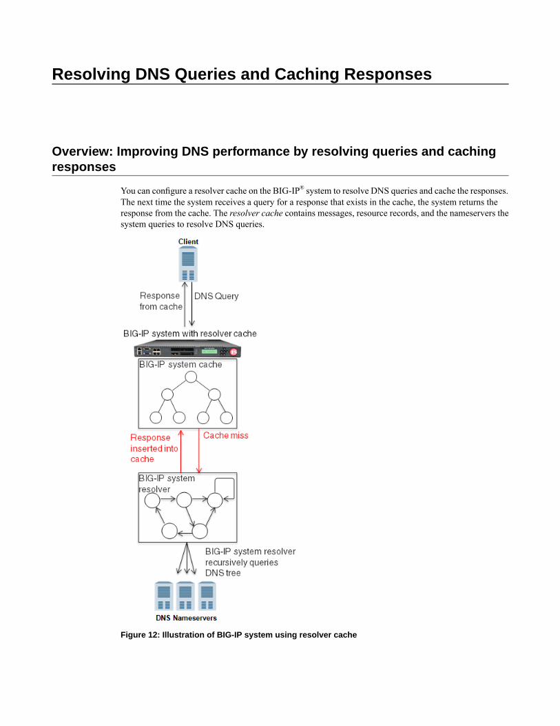
Resolving DNS Queries and Caching Responses
Overview: Improving DNS performance by resolving queries and cachingresponses
You can configure a resolver cache on the BIG-IP® system to resolve DNS queries and cache the responses.The next time the system receives a query for a response that exists in the cache, the system returns theresponse from the cache. The resolver cache contains messages, resource records, and the nameservers thesystem queries to resolve DNS queries.
Figure 12: Illustration of BIG-IP system using resolver cache

Task summary
Perform these tasks to configure a resolver cache on the BIG-IP® system.Creating a resolver DNS cacheCreating a custom DNS profile for DNS resolving and cachingAssigning a custom DNS profile to an LTM virtual serverAssigning a custom DNS profile to a GTM listenerDetermining DNS cache performanceClearing a DNS cache
Creating a resolver DNS cache
Create a resolver cache on the BIG-IP® systemwhen you want the system to resolve DNS queries and cacheresponses.
1. On the Main tab, click Local Traffic > DNS Caches > DNS Cache List.The DNS Cache List screen opens.
2. Click Create.The New DNS Cache screen opens.
3. In the Name field, type a name for the cache.4. From the Resolver Type list, select Resolver.5. Click Finished.
Associate the DNS cache with a custom DNS profile.
Creating a custom DNS profile for DNS resolving and caching
Ensure that at least one DNS cache exists on the BIG-IP® system.
You can create a customDNS profile to configure the BIG-IP® system to cache responses to DNS connectionrequests.
1. On the Main tab, click Local Traffic > Profiles > Services > DNS.The DNS profile list screen opens.
2. Click Create.The New DNS Profile screen opens.
3. In the Name field, type a name for the profile.4. Select the Custom check box.
The fields in the Settings area become available for revision.5. From the Use BIND Server on BIG-IP list, select Disabled.6. From the DNS Cache list, select Enabled.
When you enable theDNSCache option, youmust also select a DNS cache from theDNSCache Namelist.
7. From the DNS Cache Name list, select the DNS cache that you want to associate with this profile.You can associate a DNS cache with a profile, even when the DNS Cache option, is Disabled. Thisallows you to enable and disable the cache for debugging purposes.
160
Resolving DNS Queries and Caching Responses

8. Click Finished.
Assign the custom DNS profile to the virtual server handling the DNS traffic, which includes the responsesto queries that you want to cache.
Assigning a custom DNS profile to an LTM virtual server
Ensure that at least one custom DNS profile that is configured for DNS caching exists on the BIG-IP®
system.
You can assign a custom DNS profile to a virtual server to enable the BIG-IP system to perform DNScaching on the traffic the virtual server handles.
Note: This task applies only to LTM-provisioned systems.
1. On the Main tab, click Local Traffic > Virtual Servers.The Virtual Server List screen displays a list of existing virtual servers.
2. Click the name of the virtual server you want to modify.3. From the Configuration list, select Advanced.4. From the DNS Profile list, select the custom DNS profile you created.5. Click Finished.
The responses to DNS queries handled by this virtual server are cached on the BIG-IP system.
Assigning a custom DNS profile to a GTM listener
Ensure that at least one custom DNS profile that is configured for DNS caching exists on the BIG-IP®
system.
You can assign a custom DNS profile to a listener to enable the BIG-IP system to perform DNS cachingon the traffic the listener handles.
Note: This task applies only to GTM-provisioned systems.
1. On the Main tab, click Global Traffic > Listeners.The Listeners List screen opens.
2. Click the name of the listener you want to modify.3. From the DNS Profile list, select the custom DNS profile you created for DNS caching.4. Click Finished.
Determining DNS cache performance
You can view statistics to determine how well a DNS cache on the BIG-IP® system is performing.
1. On the Main tab, click Statistics >Module Statistics > Local Traffic.The Local Traffic Statistics screen opens.
2. From the Statistics Type list, select DNS Cache.3. In the Details column for a cache, click View, to display detailed information about the cache.
161
BIG-IP® Local Traffic Manager™: Implementations

4. To return to the Local Traffic Statistics screen, click Back.
Viewing records in a DNS cache
You can view records in a DNS cache to determine how well a specific cache on the BIG-IP® system isperforming.
1. Log in to the command-line interface of the BIG-IP system.2. At the BASH prompt, type tmsh.3. At the tmsh prompt, type show ltm dns cache <cache type> <cache name>, and press Enter.
For example, the command sequenceshow ltm dns cache transparent my_transparent_cache,displays the messages and resource records in the transparent cache named my_transparent_cache.
Viewing DNS cache statistics using tmsh
You can view DNS cache statistics using tmsh to determine how well a specific cache on the BIG-IP®
system is performing.
1. Log in to the command-line interface of the BIG-IP system.2. At the BASH prompt, type tmsh.3. At the tmsh prompt, type show ltm dns cache, and press Enter.
Statistics for all of the DNS caches on the BIG-IP system display.4. At the tmsh prompt, type show ltm dns cache <cache-type>, and press Enter.
For example, the command sequence show ltm dns cache transparent, displays statistics foreach of the transparent caches on the system.
5. At the tmsh prompt, type show ltm dns cache <cache type> <cache name>, and press Enter.For example, the command sequence, show ltm dns cache transparent my_t1, displays statisticsfor the transparent cache on the system named my_t1.
Managing cache size
Determine the amount of memory the BIG-IP® system has and how much you want to commit to DNScaching. View the statistics for a cache to determine how well the cache is working.
You can change the size of a DNS cache to fix cache performance issues.
1. On the Main tab, click Local Traffic > DNS Caches > DNS Cache List.The DNS Cache List screen opens.
2. Click the name of the cache you want to modify.3. In theMessage Cache Size field, type the maximum size in bytes for the DNS message cache.
The BIG-IP system caches the messages in a DNS response in the message cache. A higher maximumsize makes it possible for more DNS responses to be cached and increases the cache hit percentage. Alower maximum size forces earlier eviction of cached content, but can lower the cache hit percentage.
Important: The message cache size includes all tmms on the BIG-IP system; therefore, if there areeight tmms, multiply the size by eight and put that value in this field.
4. In theResource Record Cache Size field, type the maximum size in bytes for the DNS resource recordcache.
162
Resolving DNS Queries and Caching Responses

The BIG-IP system caches the supporting records in a DNS response in the Resource Record cache. Ahigher maximum size makes it possible for more DNS responses to be cached and increases the cachehit percentage. A lower maximum size forces earlier eviction of cached content, but can lower the cachehit percentage.
Important: The resource record cache size includes all tmms on the BIG-IP system; therefore, if thereare eight tmms, multiply the size by eight and put that value in this field.
5. In the Nameserver Cache Count field, type the maximum number of DNS nameservers for which theBIG-IP® system caches connection and capability data.
Important: The nameserver cache count includes all tmms on the BIG-IP system; therefore, if thereare eight tmms, multiply the count by eight and put that value in this field.
6. In theUnsolicited Reply Threshold field, change the default value if you are using the BIG-IP® systemto monitor for unsolicited replies using SNMP.The system always rejects unsolicited replies. The default value of 0 (off) indicates the system does notgenerate SNMP traps or log messages when rejecting unsolicited replies. Changing the default valuealerts you to a potential security attack, such as cache poisoning or DOS. For example, if you specify1,000,000 unsolicited replies, each time the system receives 1,000,000 unsolicited replies, it generatesan SNMP trap and log message.
7. Click Finished.
Clearing a DNS cache
You can clear all records from a specific DNS cache on the BIG-IP® system.
1. On the Main tab, click Local Traffic > DNS Caches > DNS Cache List.The DNS Cache List screen opens.
2. Click the Statistics tab.The Local Traffic Statistics screen opens.
3. Select the check box next to the cache you want to clear, and then click Clear Cache.
Clearing specific records from a DNS cache
You can clear specific records from a DNS cache using tmsh. For example, you can delete all RRSETrecords or only the A records in the specified cache.
Tip: In tmsh, you can use the command completion feature to discover the types of records that are availablefor deletion.
1. Log in to the command-line interface of the BIG-IP® system.2. At the BASH prompt, type tmsh.3. At the tmsh prompt, type ltm dns cache records, and press Enter to navigate to the dns cache
records module.4. Type delete <cache-type> type <record-type> cache <cache-name>, and press Enter.
For example, the command sequence delete rrset type a cache my_resolver_cache, deletesthe A records from the resource record cache of the resolver cache named my_resolver_cache.
163
BIG-IP® Local Traffic Manager™: Implementations

Implementation result
You now have an implementation in which the BIG-IP® system acts as a DNS resolver, caches DNSresponses, and answers queries for a cached response from the cache.
164
Resolving DNS Queries and Caching Responses
Resolving DNS Queries and Caching Validated Responses
Overview: Resolving queries and caching validated responses
You can configure a validating resolver cache on the BIG-IP® system to recursively query public DNSservers, validate the identity of the DNS server sending the responses, and then cache the responses. Thenext time the system receives a query for a response that exists in the cache, the system returns theDNSSEC-compliant response from the cache. The validating resolver cache contains messages, resourcerecords, the nameservers the system queries to resolve DNS queries, and DNSSEC keys.
Using the validating resolver cache, the BIG-IP system mitigates cache poisoning by validating DNSresponses using DNSSEC validation. This is important, because attackers can attempt to populate a DNScache with erroneous data that redirects clients to fake web sites, or downloads malware and viruses toclient computers. When an authoritative server signs a DNS response, the validating resolver verifies thedata before entering the data into the cache. Additionally, the validating resolver cache includes a built-infilter and detection mechanism that rejects unsolicited DNS responses.

Figure 13: Illustration of BIG-IP system using validating resolver cache
Task summary
Perform these tasks to configure a validating resolver cache on the BIG-IP® system.Creating a validating resolver DNS cacheCreating a custom DNS profile for validating resolver DNS cachingAssigning a custom DNS profile to an LTM virtual serverAssigning a custom DNS profile to a GTM listenerDetermining DNS cache performanceClearing a DNS cache
166
Resolving DNS Queries and Caching Validated Responses
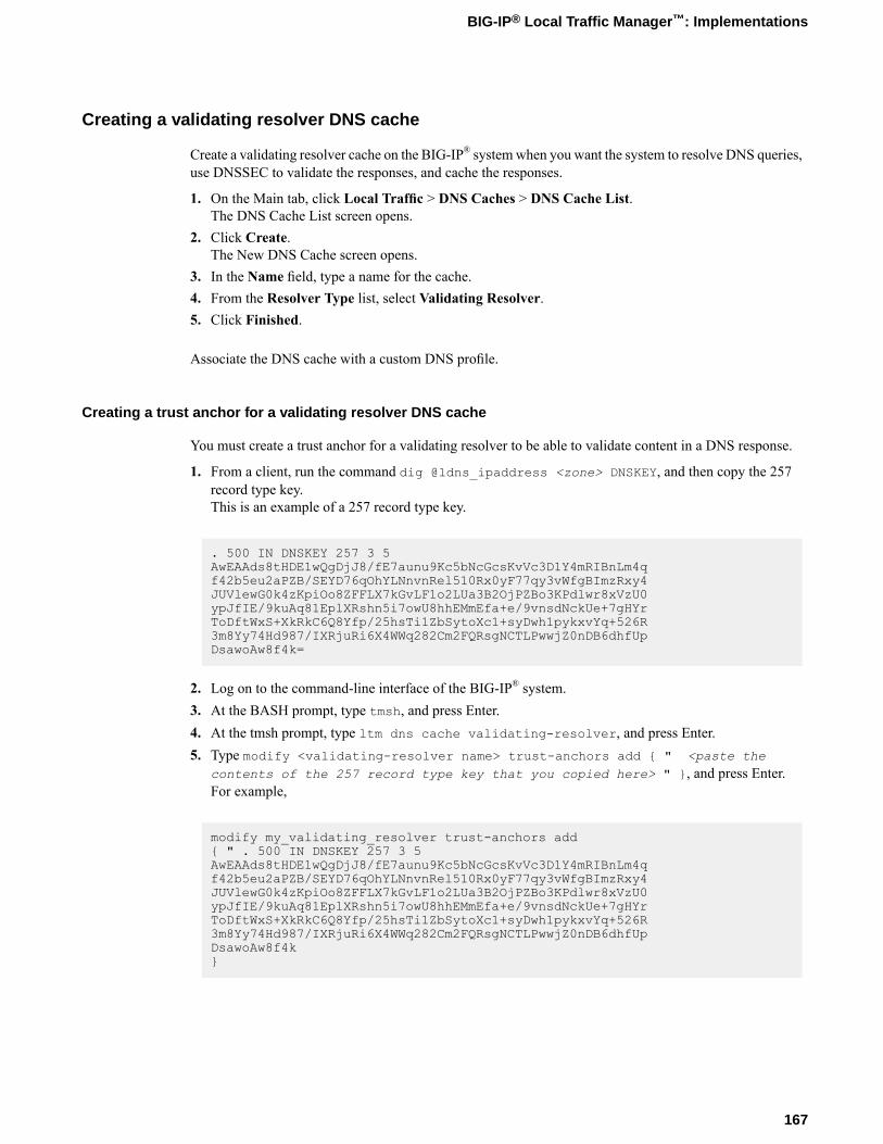
Creating a validating resolver DNS cache
Create a validating resolver cache on the BIG-IP® systemwhen you want the system to resolve DNS queries,use DNSSEC to validate the responses, and cache the responses.
1. On the Main tab, click Local Traffic > DNS Caches > DNS Cache List.The DNS Cache List screen opens.
2. Click Create.The New DNS Cache screen opens.
3. In the Name field, type a name for the cache.4. From the Resolver Type list, select Validating Resolver.5. Click Finished.
Associate the DNS cache with a custom DNS profile.
Creating a trust anchor for a validating resolver DNS cache
You must create a trust anchor for a validating resolver to be able to validate content in a DNS response.
1. From a client, run the command dig @ldns_ipaddress <zone> DNSKEY, and then copy the 257record type key.This is an example of a 257 record type key.
. 500 IN DNSKEY 257 3 5AwEAAds8tHDE1wQgDjJ8/fE7aunu9Kc5bNcGcsKvVc3D1Y4mRIBnLm4qf42b5eu2aPZB/SEYD76qOhYLNnvnRel510Rx0yF77qy3vWfgBImzRxy4JUVlewG0k4zKpiOo8ZFFLX7kGvLF1o2LUa3B2OjPZBo3KPdlwr8xVzU0ypJfIE/9kuAq81EplXRshn5i7owU8hhEMmEfa+e/9vnsdNckUe+7gHYrToDftWxS+XkRkC6Q8Yfp/25hsTi1ZbSytoXc1+syDwh1pykxvYq+526R3m8Yy74Hd987/IXRjuRi6X4WWq282Cm2FQRsgNCTLPwwjZ0nDB6dhfUpDsawoAw8f4k=
2. Log on to the command-line interface of the BIG-IP® system.3. At the BASH prompt, type tmsh, and press Enter.4. At the tmsh prompt, type ltm dns cache validating-resolver, and press Enter.5. Type modify <validating-resolver name> trust-anchors add { " <paste the
contents of the 257 record type key that you copied here> " }, and press Enter.For example,
modify my_validating_resolver trust-anchors add{ " . 500 IN DNSKEY 257 3 5AwEAAds8tHDE1wQgDjJ8/fE7aunu9Kc5bNcGcsKvVc3D1Y4mRIBnLm4qf42b5eu2aPZB/SEYD76qOhYLNnvnRel510Rx0yF77qy3vWfgBImzRxy4JUVlewG0k4zKpiOo8ZFFLX7kGvLF1o2LUa3B2OjPZBo3KPdlwr8xVzU0ypJfIE/9kuAq81EplXRshn5i7owU8hhEMmEfa+e/9vnsdNckUe+7gHYrToDftWxS+XkRkC6Q8Yfp/25hsTi1ZbSytoXc1+syDwh1pykxvYq+526R3m8Yy74Hd987/IXRjuRi6X4WWq282Cm2FQRsgNCTLPwwjZ0nDB6dhfUpDsawoAw8f4k}
167
BIG-IP® Local Traffic Manager™: Implementations

Creating a custom DNS profile for validating resolver DNS caching
Ensure that at least one DNS cache exists on the BIG-IP® system.
You can create a customDNS profile to configure the BIG-IP® system to cache responses to DNS connectionrequests.
1. On the Main tab, click Local Traffic > Profiles > Services > DNS.The DNS profile list screen opens.
2. Click Create.The New DNS Profile screen opens.
3. In the Name field, type a name for the profile.4. In the Parent Profile list, accept the default dns profile.5. Select the Custom check box.
The fields in the Settings area become available for revision.6. From the Use BIND Server on BIG-IP list, select Disabled.7. From the DNS Cache list, select Enabled.
When you enable theDNSCache option, youmust also select a DNS cache from theDNSCache Namelist.
8. From the DNS Cache Name list, select the DNS cache that you want to associate with this profile.You can associate a DNS cache with a profile, even when the DNS Cache option, is Disabled. Thisallows you to enable and disable the cache for debugging purposes.
9. Click Finished.
Assign the custom DNS profile to the virtual server that handles the DNS traffic that includes the responsesto queries that you want to cache.
Assigning a custom DNS profile to an LTM virtual server
Ensure that at least one custom DNS profile that is configured for DNS caching exists on the BIG-IP®
system.
You can assign a custom DNS profile to a virtual server to enable the BIG-IP system to perform DNScaching on the traffic the virtual server handles.
Note: This task applies only to LTM-provisioned systems.
1. On the Main tab, click Local Traffic > Virtual Servers.The Virtual Server List screen displays a list of existing virtual servers.
2. Click the name of the virtual server you want to modify.3. From the Configuration list, select Advanced.4. From the DNS Profile list, select the custom DNS profile you created.5. Click Finished.
The responses to DNS queries handled by this virtual server are cached on the BIG-IP system.
168
Resolving DNS Queries and Caching Validated Responses

Assigning a custom DNS profile to a GTM listener
Ensure that at least one custom DNS profile that is configured for DNS caching exists on the BIG-IP®
system.
You can assign a custom DNS profile to a listener to enable the BIG-IP system to perform DNS cachingon the traffic the listener handles.
Note: This task applies only to GTM-provisioned systems.
1. On the Main tab, click Global Traffic > Listeners.The Listeners List screen opens.
2. Click the name of the listener you want to modify.3. From the DNS Profile list, select the custom DNS profile you created for DNS caching.4. Click Finished.
Determining DNS cache performance
You can view statistics to determine how well a DNS cache on the BIG-IP® system is performing.
1. On the Main tab, click Statistics >Module Statistics > Local Traffic.The Local Traffic Statistics screen opens.
2. From the Statistics Type list, select DNS Cache.3. In the Details column for a cache, click View, to display detailed information about the cache.4. To return to the Local Traffic Statistics screen, click Back.
Viewing records in a DNS cache
You can view records in a DNS cache to determine how well a specific cache on the BIG-IP® system isperforming.
1. Log in to the command-line interface of the BIG-IP system.2. At the BASH prompt, type tmsh.3. At the tmsh prompt, type show ltm dns cache <cache type> <cache name>, and press Enter.
For example, the command sequenceshow ltm dns cache transparent my_transparent_cache,displays the messages and resource records in the transparent cache named my_transparent_cache.
Viewing DNS cache statistics using tmsh
You can view DNS cache statistics using tmsh to determine how well a specific cache on the BIG-IP®
system is performing.
1. Log in to the command-line interface of the BIG-IP system.2. At the BASH prompt, type tmsh.3. At the tmsh prompt, type show ltm dns cache, and press Enter.
Statistics for all of the DNS caches on the BIG-IP system display.4. At the tmsh prompt, type show ltm dns cache <cache-type>, and press Enter.
169
BIG-IP® Local Traffic Manager™: Implementations

For example, the command sequence show ltm dns cache transparent, displays statistics foreach of the transparent caches on the system.
5. At the tmsh prompt, type show ltm dns cache <cache type> <cache name>, and press Enter.For example, the command sequence, show ltm dns cache transparent my_t1, displays statisticsfor the transparent cache on the system named my_t1.
Managing cache size
Determine the amount of memory the BIG-IP® system has and how much you want to commit to DNScaching. View the statistics for a cache to determine how well the cache is working.
You can change the size of a DNS cache to fix cache performance issues.
1. On the Main tab, click Local Traffic > DNS Caches > DNS Cache List.The DNS Cache List screen opens.
2. Click the name of the cache you want to modify.3. In theMessage Cache Size field, type the maximum size in bytes for the DNS message cache.
The BIG-IP system caches the messages in a DNS response in the message cache. A higher maximumsize makes it possible for more DNS responses to be cached and increases the cache hit percentage. Alower maximum size forces earlier eviction of cached content, but can lower the cache hit percentage.
Important: The message cache size includes all tmms on the BIG-IP system; therefore, if there areeight tmms, multiply the size by eight and put that value in this field.
4. In theResource Record Cache Size field, type the maximum size in bytes for the DNS resource recordcache.The BIG-IP system caches the supporting records in a DNS response in the Resource Record cache. Ahigher maximum size makes it possible for more DNS responses to be cached and increases the cachehit percentage. A lower maximum size forces earlier eviction of cached content, but can lower the cachehit percentage.
Important: The resource record cache size includes all tmms on the BIG-IP system; therefore, if thereare eight tmms, multiply the size by eight and put that value in this field.
5. In the Nameserver Cache Count field, type the maximum number of DNS nameservers for which theBIG-IP® system caches connection and capability data.
Important: The nameserver cache count includes all tmms on the BIG-IP system; therefore, if thereare eight tmms, multiply the count by eight and put that value in this field.
6. In theUnsolicited Reply Threshold field, change the default value if you are using the BIG-IP® systemto monitor for unsolicited replies using SNMP.The system always rejects unsolicited replies. The default value of 0 (off) indicates the system does notgenerate SNMP traps or log messages when rejecting unsolicited replies. Changing the default valuealerts you to a potential security attack, such as cache poisoning or DOS. For example, if you specify1,000,000 unsolicited replies, each time the system receives 1,000,000 unsolicited replies, it generatesan SNMP trap and log message.
7. Click Finished.
170
Resolving DNS Queries and Caching Validated Responses

Clearing a DNS cache
You can clear all records from a specific DNS cache on the BIG-IP® system.
1. On the Main tab, click Local Traffic > DNS Caches > DNS Cache List.The DNS Cache List screen opens.
2. Click the Statistics tab.The Local Traffic Statistics screen opens.
3. Select the check box next to the cache you want to clear, and then click Clear Cache.
Clearing specific records from a DNS cache
You can clear specific records from a DNS cache using tmsh. For example, you can delete all RRSETrecords or only the A records in the specified cache.
Tip: In tmsh, you can use the command completion feature to discover the types of records that are availablefor deletion.
1. Log in to the command-line interface of the BIG-IP® system.2. At the BASH prompt, type tmsh.3. At the tmsh prompt, type ltm dns cache records, and press Enter to navigate to the dns cache
records module.4. Type delete <cache-type> type <record-type> cache <cache-name>, and press Enter.
For example, the command sequence delete rrset type a cache my_resolver_cache, deletesthe A records from the resource record cache of the resolver cache named my_resolver_cache.
Implementation result
You now have an implementation in which the BIG-IP® system acts as a DNS resolver, verifies the validityof the responses, caches DNSSEC-compliant responses, and answers queries for a cached response with aDNSSEC-compliant response from the cache.
171
BIG-IP® Local Traffic Manager™: Implementations


Customizing a DNS Cache
Overview: Customizing a DNS cache
You can customize a DNS cache on the BIG-IP® system to meet specific network needs by changing thedefault values on the DNS cache settings.
Configuring a DNS cache to answer queries for local zones
You can configure a DNS cache on the BIG-IP® system to answer client requests for local zones.
1. On the Main tab, click Local Traffic > DNS Caches > DNS Cache List.The DNS Cache List screen opens.
2. Click the name of the cache you want to modify.3. Select the Enabled check box for the Answer Default Zones setting, when you want the BIG-IP®
system to answer queries for the default zones: localhost, reverse 127.0.0.1 and ::1, and AS112 zones.4. Click Update.
Configuring a DNS cache to use specific root nameservers
You can configure a resolver or validating resolver DNS cache on the BIG-IP® system to use a specificserver as an authoritative nameserver for the DNS root nameservers.
1. On the Main tab, click Local Traffic > DNS Caches > DNS Cache List.The DNS Cache List screen opens.
2. Click the name of the cache you want to modify.3. In the Root Hints section, in the IP address field, type the IP address of a DNS server that the system
considers authoritative for the DNS root nameservers, and then click Add.
Caution: By default, the system uses the DNS root nameservers published by InterNIC. When you addDNS root nameservers, the BIG-IP system no longer uses the default nameservers published by InterNIC,but uses the nameservers you add as authoritative for the DNS root nameservers.
Based on your network configuration, add IPv4 or IPv6 addresses or both.
4. Click Update.

Configuring a DNS cache alert for cache poisoning
You can configure a resolver or validating resolver DNS cache on the BIG-IP® system to generate SNMPalerts and log messages when the cache receives unsolicited replies. This is helpful as an alert to a potentialsecurity attack, such as cache poisoning or DOS.
1. On the Main tab, click Local Traffic > DNS Caches > DNS Cache List.The DNS Cache List screen opens.
2. Click the name of the cache you want to modify.3. In theUnsolicited Reply Threshold field, change the default value if you are using the BIG-IP® system
to monitor for unsolicited replies using SNMP.The system always rejects unsolicited replies. The default value of 0 (off) indicates the system does notgenerate SNMP traps or log messages when rejecting unsolicited replies. Changing the default valuealerts you to a potential security attack, such as cache poisoning or DOS. For example, if you specify1,000,000 unsolicited replies, each time the system receives 1,000,000 unsolicited replies, it generatesan SNMP trap and log message.
4. Click Update.
174
Customizing a DNS Cache
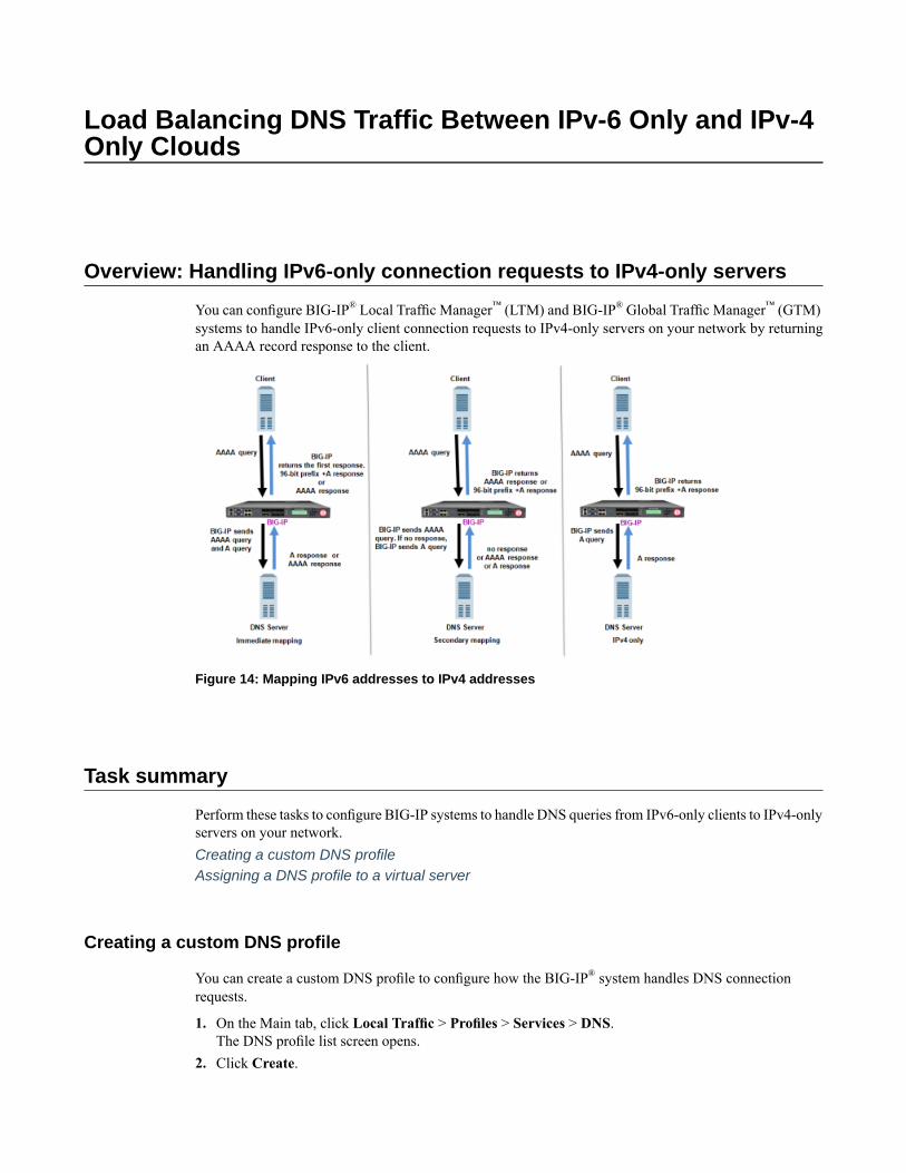
Load Balancing DNS Traffic Between IPv-6 Only and IPv-4Only Clouds
Overview: Handling IPv6-only connection requests to IPv4-only servers
You can configure BIG-IP® Local Traffic Manager™ (LTM) and BIG-IP® Global Traffic Manager™ (GTM)systems to handle IPv6-only client connection requests to IPv4-only servers on your network by returningan AAAA record response to the client.
Figure 14: Mapping IPv6 addresses to IPv4 addresses
Task summary
Perform these tasks to configure BIG-IP systems to handle DNS queries from IPv6-only clients to IPv4-onlyservers on your network.Creating a custom DNS profileAssigning a DNS profile to a virtual server
Creating a custom DNS profile
You can create a custom DNS profile to configure how the BIG-IP® system handles DNS connectionrequests.
1. On the Main tab, click Local Traffic > Profiles > Services > DNS.The DNS profile list screen opens.
2. Click Create.
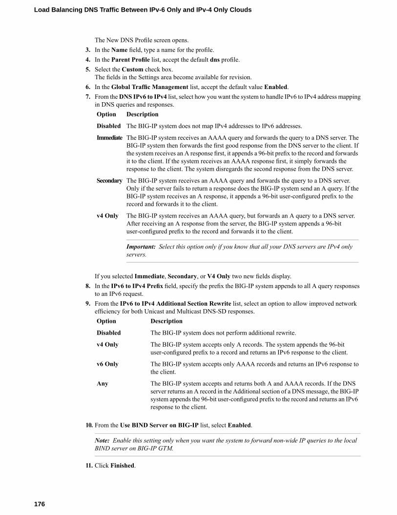
The New DNS Profile screen opens.3. In the Name field, type a name for the profile.4. In the Parent Profile list, accept the default dns profile.5. Select the Custom check box.
The fields in the Settings area become available for revision.6. In the Global Traffic Management list, accept the default value Enabled.7. From theDNS IPv6 to IPv4 list, select how you want the system to handle IPv6 to IPv4 address mapping
in DNS queries and responses.DescriptionOption
The BIG-IP system does not map IPv4 addresses to IPv6 addresses.Disabled
The BIG-IP system receives an AAAA query and forwards the query to a DNS server. TheBIG-IP system then forwards the first good response from the DNS server to the client. If
Immediate
the system receives an A response first, it appends a 96-bit prefix to the record and forwardsit to the client. If the system receives an AAAA response first, it simply forwards theresponse to the client. The system disregards the second response from the DNS server.
The BIG-IP system receives an AAAA query and forwards the query to a DNS server.Only if the server fails to return a response does the BIG-IP system send an A query. If the
Secondary
BIG-IP system receives an A response, it appends a 96-bit user-configured prefix to therecord and forwards it to the client.
The BIG-IP system receives an AAAA query, but forwards an A query to a DNS server.After receiving an A response from the server, the BIG-IP system appends a 96-bituser-configured prefix to the record and forwards it to the client.
Important: Select this option only if you know that all your DNS servers are IPv4 onlyservers.
v4 Only
If you selected Immediate, Secondary, or V4 Only two new fields display.8. In the IPv6 to IPv4 Prefix field, specify the prefix the BIG-IP system appends to all A query responses
to an IPv6 request.9. From the IPv6 to IPv4 Additional Section Rewrite list, select an option to allow improved network
efficiency for both Unicast and Multicast DNS-SD responses.DescriptionOption
The BIG-IP system does not perform additional rewrite.Disabled
The BIG-IP system accepts only A records. The system appends the 96-bituser-configured prefix to a record and returns an IPv6 response to the client.
v4 Only
The BIG-IP system accepts only AAAA records and returns an IPv6 response tothe client.
v6 Only
The BIG-IP system accepts and returns both A and AAAA records. If the DNSserver returns an A record in the Additional section of a DNSmessage, the BIG-IP
Any
system appends the 96-bit user-configured prefix to the record and returns an IPv6response to the client.
10. From the Use BIND Server on BIG-IP list, select Enabled.
Note: Enable this setting only when you want the system to forward non-wide IP queries to the localBIND server on BIG-IP GTM.
11. Click Finished.
176
Load Balancing DNS Traffic Between IPv-6 Only and IPv-4 Only Clouds

Assigning a DNS profile to a virtual server
1. On the Main tab, click Local Traffic > Virtual Servers.The Virtual Server List screen displays a list of existing virtual servers.
2. Click the name of the virtual server you want to modify.3. From the DNS Profile list, select the profile you created to manage IPv6 to IPv4 address mapping.4. Click Update.
This virtual server can now pass traffic between an IPv6-only client and an IPv4-only DNS server.
Implementation result
You now have an implementation in which the BIG-IP® system handles connection requests from anIPv6-only client to an IPv4-only server.
177
BIG-IP® Local Traffic Manager™: Implementations

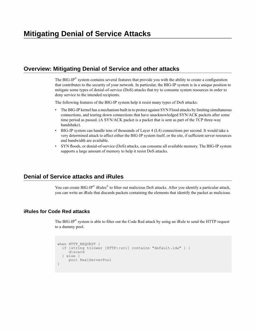
Mitigating Denial of Service Attacks
Overview: Mitigating Denial of Service and other attacks
The BIG-IP® system contains several features that provide you with the ability to create a configurationthat contributes to the security of your network. In particular, the BIG-IP system is in a unique position tomitigate some types of denial-of-service (DoS) attacks that try to consume system resources in order todeny service to the intended recipients.
The following features of the BIG-IP system help it resist many types of DoS attacks:
• The BIG-IP kernel has amechanism built in to protect against SYNFlood attacks by limiting simultaneousconnections, and tearing down connections that have unacknowledged SYN/ACK packets after sometime period as passed. (A SYN/ACK packet is a packet that is sent as part of the TCP three-wayhandshake).
• BIG-IP system can handle tens of thousands of Layer 4 (L4) connections per second. It would take avery determined attack to affect either the BIG-IP system itself, or the site, if sufficient server resourcesand bandwidth are available.
• SYN floods, or denial-of-service (DoS) attacks, can consume all available memory. The BIG-IP systemsupports a large amount of memory to help it resist DoS attacks.
Denial of Service attacks and iRules
You can create BIG-IP® iRules® to filter out malicious DoS attacks. After you identify a particular attack,you can write an iRule that discards packets containing the elements that identify the packet as malicious.
iRules for Code Red attacks
The BIG-IP® system is able to filter out the Code Red attack by using an iRule to send the HTTP requestto a dummy pool.
when HTTP_REQUEST {if {string tolower [HTTP::uri] contains "default.ida" } {
discard} else {
pool RealServerPool}

iRules for Nimda attacks
TheNimdaworm is designed to attack systems and applications based on theMicrosoft®Windows® operatingsystem.
when HTTP_REQUEST {set uri [string tolower [HTTP::uri]]if { ($uri contains "cmd.exe") or ($uri contains
"root.exe") or ($uri contains "admin.dll") } {discard
} else {pool ServerPool
}}
Common Denial of Service attacks
You might want to know how the BIG-IP® system reacts to certain common attacks that are designed todeny service by breaking the service or the network devices. The following information lists the mostcommon attacks, along with how the BIG-IP system functionality handles the attack.
MitigationDescriptionAttacktype
The BIG-IP system includes afeature designed to alleviate SYN
A SYN flood is an attack against a system for the purposeof exhausting that system's resources. An attacker launching
SYNflood
flooding. Known as SYN Check™,a SYN flood against a target system attempts to occupy allthis feature sends information aboutavailable resources used to establish TCP connections bythe flow, in the form of cookies, tosending multiple SYN segments containing incorrect IPthe requesting client, so that theaddresses. Note that the term SYN refers to a type ofsystem does not need to keep theconnection state that occurs during establishment of aSYN-RECEIVED state that isTCP/IP connection. More specifically, a SYN flood isnormally stored in the connectiondesigned to fill up a SYN queue. A SYN queue is a set oftable for the initiated session.connections stored in the connection table in theBecause the SYN-RECEIVED stateSYN-RECEIVED state, as part of the standard three-wayis not kept for a connection, the SYNTCP handshake. A SYN queue can hold a specifiedqueue cannot be exhausted, andmaximumnumber of connections in the SYN-RECEIVEDnormal TCP communication canstate. Connections in the SYN-RECEIVED state arecontinue. The SYN Check featureconsidered to be half-open and waiting for ancomplements the existing adaptiveacknowledgment from the client.When a SYNflood causesreaper feature in the BIG-IP system.the maximum number of allowed connections in theWhile the adaptive reaper handlesSYN-RECEIVED state to be reached, the SYN queue isestablished connection flooding,said to be full, thus preventing the target system fromSYN Check prevents connectionestablishing other legitimate connections. A full SYN queueflooding altogether. That is, whiletherefore results in partially-open TCP connections to IPthe adaptive reaper must workaddresses that either do not exist or are unreachable. Inovertime to flush connections, thethese cases, the connectionsmust reach their timeout before
the server can continue fulfilling other requests. SYN Check feature prevents theSYN queue from becoming full, thusallowing the target system to
180
Mitigating Denial of Service Attacks

MitigationDescriptionAttacktype
continue to establish TCPconnections.
You do not need to make anychanges to the BIG-IP systemconfiguration for this type of attack.
The ICMP flood, sometimes referred to as a Smurf attack,is an attack based on a method of making a remote networksend ICMP Echo replies to a single host. In this attack, asingle packet from the attacker goes to an unprotected
ICMPflood(Smurf)
network's broadcast address. Typically, this causes everymachine on that network to answer with a packet sent tothe target. The BIG-IP system is hardened against theseattacks because it answers only a limited number of ICMPrequests per second, and then drops the rest. On the networkinside the BIG-IP system, the BIG-IP system ignoresdirected subnet broadcasts, and does not respond to thebroadcast ICMP Echo that a Smurf attacker uses to initiatean attack.
Setting the UDP idle session timeoutto between 5 and 10 seconds reaps
The UDP flood attack is most commonly a distributeddenial-of-service attack (DDoS), where multiple remote
UDPflood
these connections quickly withoutsystems are sending a large flood of UDP packets to theimpacting users with slowtarget. The BIG-IP system handles these attacks similarlyconnections. However, with UDPto the way it handles a SYN flood. If the port is notthis might still leave too many openlistening, the BIG-IP system drops the packets. If the port
is listening, the reaper removes the false connections. connections, and your situationmight require a setting of between 2and 5 seconds.
You do not need to make anychanges to the BIG-IP systemconfiguration for this type of attack.
The UDP fragment attack is based on forcing the systemto reassemble huge amounts of UDP data sent asfragmented packets. The goal of this attack is to consumesystem resources to the point where the system fails. The
UDPfragment
BIG-IP system does not reassemble these packets, it sendsthem on to the server if they are for an open UDP service.If these packets are sent with the initial packet opening theconnection correctly, then the connection is sent to theback-end server. If the initial packet is not the first packetof the stream, the entire stream is dropped.
You do not need to make anychanges to the BIG-IP systemconfiguration for this type of attack.
The Ping of Death attack is an attack with ICMP echopackets that are larger than 65535 bytes. As this is themaximum allowed ICMP packet size, this can crashsystems that attempt to reassemble the packet. The BIG-IP
Ping ofDeath
system is hardened against this type of attack. However,if the attack is against a virtual server with the Any IPfeature enabled, then these packets are sent on to the server.It is important that you apply the latest updates to yourservers.
You do not need to make anychanges to the BIG-IP systemconfiguration for this type of attack.
A Land attack is a SYN packet sent with the source addressand port the same as the destination address and port. TheBIG-IP system is hardened to resist this attack. The BIG-IPsystem connection table matches existing connections so
Land
that a spoof of this sort is not passed on to the servers.Connections to the BIG-IP system are checked and droppedif spoofed in this manner.
181
BIG-IP® Local Traffic Manager™: Implementations
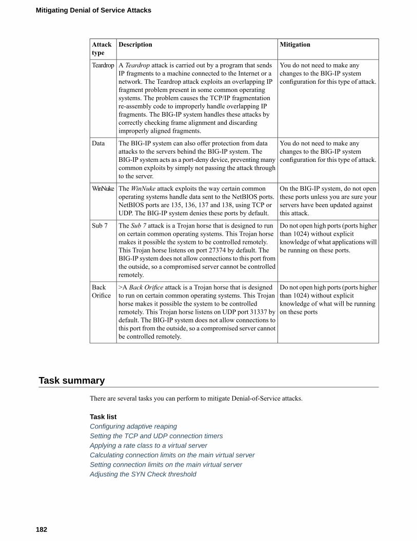
MitigationDescriptionAttacktype
You do not need to make anychanges to the BIG-IP systemconfiguration for this type of attack.
A Teardrop attack is carried out by a program that sendsIP fragments to a machine connected to the Internet or anetwork. The Teardrop attack exploits an overlapping IPfragment problem present in some common operating
Teardrop
systems. The problem causes the TCP/IP fragmentationre-assembly code to improperly handle overlapping IPfragments. The BIG-IP system handles these attacks bycorrectly checking frame alignment and discardingimproperly aligned fragments.
You do not need to make anychanges to the BIG-IP systemconfiguration for this type of attack.
The BIG-IP system can also offer protection from dataattacks to the servers behind the BIG-IP system. TheBIG-IP system acts as a port-deny device, preventingmanycommon exploits by simply not passing the attack throughto the server.
Data
On the BIG-IP system, do not openthese ports unless you are sure your
TheWinNuke attack exploits the way certain commonoperating systems handle data sent to the NetBIOS ports.
WinNuke
servers have been updated againstthis attack.
NetBIOS ports are 135, 136, 137 and 138, using TCP orUDP. The BIG-IP system denies these ports by default.
Do not open high ports (ports higherthan 1024) without explicit
The Sub 7 attack is a Trojan horse that is designed to runon certain common operating systems. This Trojan horse
Sub 7
knowledge of what applications willbe running on these ports.
makes it possible the system to be controlled remotely.This Trojan horse listens on port 27374 by default. TheBIG-IP system does not allow connections to this port fromthe outside, so a compromised server cannot be controlledremotely.
Do not open high ports (ports higherthan 1024) without explicit
>A Back Orifice attack is a Trojan horse that is designedto run on certain common operating systems. This Trojan
BackOrifice
knowledge of what will be runningon these ports
horse makes it possible the system to be controlledremotely. This Trojan horse listens on UDP port 31337 bydefault. The BIG-IP system does not allow connections tothis port from the outside, so a compromised server cannotbe controlled remotely.
Task summary
There are several tasks you can perform to mitigate Denial-of-Service attacks.
Task listConfiguring adaptive reapingSetting the TCP and UDP connection timersApplying a rate class to a virtual serverCalculating connection limits on the main virtual serverSetting connection limits on the main virtual serverAdjusting the SYN Check threshold
182
Mitigating Denial of Service Attacks

Configuring adaptive reaping
This procedure configures adaptive reaping. The adaptive connection reaper closes idle connections whenmemory usage on the BIG-IP system increases. This feature makes it possible for the BIG-IP system toaggressively reap connections when the systemmemory utilization reaches the low-water mark, and to stopestablishing new connections when the systemmemory utilization reaches the high-water mark percentage.
If the BIG-IP platform includes an LCD panel, an adaptive reaping event causes the BIG-IP system todisplay the following message on the LCD panel:
Blocking DoS attack
Caution: The adaptive reaper settings do not apply to SSL connections. However, you can set TCP andUDP connection timeouts that reap idle SSL connections.
1. On the Main tab, click System > Configuration.The General screen opens.
2. From the Local Traffic menu, choose General.3. In the Properties area of the screen, set the Reaper High-water Mark property to 95.4. Set the Reaper Low-water Mark property to 85.5. Click Update.
When aggressive mode is activated on the BIG-IP system, the event is marked in the /var/log/ltm filewith messages similar to these examples:
tmm tmm[PID]: 011e0002:4: sweeper_update: aggressive mode activated. (117504/138240 pages)
tmm tmm[PID]: 011e0002:4: sweeper_update: aggressive mode deactivated. (117503/138240 pages)
Important: Setting both of the adaptive reaper values to 100 disables this feature.
Setting the TCP and UDP connection timers
You can set the TCP and UDP timers in the profile settings for the TCP profile and the UDP profiles. Youshould set these timers for the services that you use for your virtual servers. For example, you can set avalue of 60 for HTTP connections and 60 for SSL connections.
1. On the Main tab, click Local Traffic > Profiles.2. From the Protocol menu, choose TCP or UDP.3. Click the name of the profile type you want to configure.4. Set the Idle Timeout setting to 60.5. Click Update.
Applying a rate class to a virtual server
After you create a rate class, you can apply it to the virtual servers in the configuration.
1. On the Main tab, click Local Traffic > Virtual Servers.
183
BIG-IP® Local Traffic Manager™: Implementations

The Virtual Server List screen displays a list of existing virtual servers.2. In the Virtual Server list, click the virtual server that you want.3. In the Configuration list, click Advanced.4. In the Rate Class list, select a rate class.5. Click Update.
The rate class is applied to the virtual server.
Calculating connection limits on the main virtual server
Use this procedure to set a connection limit for a virtual server.
Use the following formula to figure out what to set the connection limit value to on the main virtualserver: Connection Limit = Approximate Amount of RAM in kilobytes * 0.8.If you have 256 MB of RAM, the calculation is: 256,000 * 0.8 = 204800In this case, you set the connection limit to 204800.
Setting connection limits on the main virtual server
Connection limits determine the maximum number of concurrent connections allowed on a virtual server.In this context, the main virtual server is the virtual server that receives the most traffic to your site.
1. On the Main tab, click Local Traffic > Virtual Servers.The Virtual Server List screen displays a list of existing virtual servers.
2. Click the virtual server that you want to modify.3. From the Configuration list, select Advanced.4. In the Connection Limit field, type a number that specifies the maximum number of concurrent open
connections.5. In theConnectionRate Limit field, type a number that specifies the number of new connections accepted
per second.6. Click Update to save your changes.
The virtual server is configured for the specified maximum number of concurrent connections.
Adjusting the SYN Check threshold
You can configure the SYN Check™ feature to prevent the BIG-IP SYN queue from becoming full duringa SYN flood attack. The SYNCheckActivation Threshold setting indicates the number of new or untrustedTCP connections that can be established before the BIG-IP activates the SYNCookies authenticationmethodfor subsequent TCP connections.
1. On the Main tab, click System > Configuration.2. From the Local Traffic menu, choose General.3. In the SYN Check Activation Threshold field, type the number of connections that you want to define
for the threshold.4. Click Update.
If SYN flooding occurs, the BIG-IP system now protects the BIG-IP SYN queue from becoming full.
184
Mitigating Denial of Service Attacks

Configuring Remote CRLDP Authentication
Overview of remote authentication for application traffic
As an administrator in a large computing environment, you can set up the BIG-IP system to use this serverto authenticate any network traffic passing through the BIG-IP system. This type of traffic passes througha virtual server and through Traffic Management Microkernel (TMM) interfaces. Remote authenticationservers typically use one of these protocols:
• Lightweight Directory Access Protocol (LDAP)• Remote Authentication Dial-in User Service (RADIUS)• TACACS+ (derived from Terminal Access Controller Access Control System [TACACS])• Online Status Certificate Protocol (OCSP)• Certificate Revocation List Distribution Point (CRLDP)• Kerberos
To configure remote authentication for this type of traffic, you must create a configuration object and aprofile that correspond to the type of authentication server you are using to store your user accounts. Forexample, if your remote authentication server is an LDAP server, you create an LDAP configuration objectand an LDAP profile. When implementing a RADIUS, SSL OCSP, or CRLDP authentication module, youmust also create a third type of object. For RADIUS and CRLDP authentication, this object is referred toas a server object. For SSL OCSP authentication, this object is referred to as an OCSP responder.
Task Summary
To configure remote authentication with CRLDP, you must create a configuration object and a profile thatcorrespond to the authentication server you are using to store your user accounts. You must also create athird type of object. This object is referred to as a server object.
Task listCreating a CRLDP configuration object for authenticating application traffic remotelyCreating a custom CRLDP profileModifying a virtual server for CRLDP authentication
Creating a CRLDP configuration object for authenticating application traffic remotely
The CRLDP authentication module verifies the revocation status of an SSL certificate, as part ofauthenticating that certificate. A CRLDP configuration object specifies information that the BIG-IP systemneeds to perform the remote authentication.
1. On the Main tab of the navigation pane, click Local Traffic > Profiles.2. From the Authentication menu, choose Configurations.3. Click Create.

4. In the Name field, type a unique name for the configuration object, such asmy_crldp_config.5. From the Type list, select CRLDP.6. In the Connection Timeout field, retain or change the time limit, in seconds, for the connection to the
Certificate Revocation List Distribution Points (CRLDP) server.7. In the Update Interval field, retain or change the interval, in seconds, for the system to use when
receiving updates from the CRLDP server.If you use the default value of 0 (zero), the CRLDP server updates the system according to the expirationtime specified for the CRL.
8. For the Use Issuer setting, retain the default value (cleared) or select the box.When cleared (disabled), the BIG-IP system extracts the CRL distribution point from the incoming clientcertificate. When selected (enabled), the BIG-IP system extracts the CRL distribution point from thesigning certificate.
9. For theCRLDP Servers setting, select a CRLDP server name in theAvailable list, and using the Movebutton, move the name to the Selected list.
10. Click Finished.
You now have a CRLDP configuration object that a CRLDP profile can reference.
Creating a custom CRLDP profile
The next task in configuring CRLDP-based remote authentication on the BIG-IP® system is to create acustom CRLDP profile.
1. On the Main tab, click Local Traffic > Profiles > Authentication > Profiles.The Profiles list screen opens.
2. Click Create.The New Authentication Profile screen opens.
3. In the Name field, type a name for the profile.4. Select CRLDP from the Type list.5. Select ssl_crldp in the Parent Profile list.6. Select the Custom check box.
The fields in the Settings area become available for revision.7. Select a CRLDP configuration object from the Configuration list.8. Click Finished.
Modifying a virtual server for CRLDP authentication
The final task in the process of implementing CRLDP authentication is to assign the custom CRLDP profileto a virtual server that is configured to process HTTP traffic (that is, a virtual server to which an HTTPprofile is assigned).
1. On the Main tab, click Local Traffic > Virtual Servers.The Virtual Server List screen displays a list of existing virtual servers.
2. Click the name of a virtual server.3. From the Configuration list, select Advanced.4. For the Authentication Profiles setting, in the Available field, select a custom CRLDP profile, and
using theMove button, move the custom CRLDP profile to the Selected field.
186
Configuring Remote CRLDP Authentication

5. Click Update to save your changes.
The virtual server is assigned the custom CRLDP profile.
187
BIG-IP® Local Traffic Manager™: Implementations


Configuring Remote SSL LDAP Authentication
Overview of remote SSL LDAP authentication for application traffic
As an administrator in a large computing environment, you can set up the BIG-IP system to use this serverto authenticate any network traffic passing through the BIG-IP system. This type of traffic passes througha virtual server and through Traffic Management Microkernel (TMM) interfaces. Remote authenticationservers typically use one of these protocols:
• Lightweight Directory Access Protocol (LDAP)• Remote Authentication Dial-in User Service (RADIUS)• TACACS+ (derived from Terminal Access Controller Access Control System [TACACS])• Online Status Certificate Protocol (OCSP)• Certificate Revocation List Distribution Point (CRLDP)• Kerberos
To configure remote authentication for this type of traffic, you must create a configuration object and aprofile that correspond to the type of authentication server you are using to store your user accounts. Forexample, if your remote authentication server is an LDAP server, you create an LDAP configuration objectand an LDAP profile. When implementing a RADIUS, SSL OCSP, or CRLDP authentication module, youmust also create a third type of object. For RADIUS and CRLDP authentication, this object is referred toas a server object. For SSL OCSP authentication, this object is referred to as an OCSP responder.
Task Summary
To configure remote authentication for SSL LDAP traffic, you must create a configuration object and aprofile that correspond to the type of authentication server you are using to store your user accounts.
Task listCreating an LDAP Client Certificate SSL configuration objectCreating a custom SSL Client Certificate LDAP profileModifying a virtual server for SSL Client Certificate LDAP authorization
Creating an LDAP Client Certificate SSL configuration object
An SSL Client Certificate LDAP configuration object specifies information that the BIG-IP system needsto perform the remote authentication. This configuration object is one of the required objects you need toimpose certificate-based access control on application traffic.
1. On the Main tab of the navigation pane, click Local Traffic > Profiles.2. From the Authentication menu, choose Configurations.3. Click Create.4. In the Name field, type a unique name for the configuration object, such asmy_ssl_ldap_config.
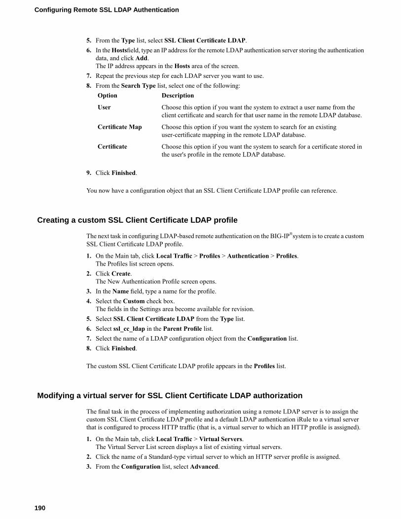
5. From the Type list, select SSL Client Certificate LDAP.6. In theHostsfield, type an IP address for the remote LDAP authentication server storing the authentication
data, and click Add.The IP address appears in the Hosts area of the screen.
7. Repeat the previous step for each LDAP server you want to use.8. From the Search Type list, select one of the following:
DescriptionOption
Choose this option if you want the system to extract a user name from theclient certificate and search for that user name in the remote LDAP database.
User
Choose this option if you want the system to search for an existinguser-certificate mapping in the remote LDAP database.
Certificate Map
Choose this option if you want the system to search for a certificate stored inthe user's profile in the remote LDAP database.
Certificate
9. Click Finished.
You now have a configuration object that an SSL Client Certificate LDAP profile can reference.
Creating a custom SSL Client Certificate LDAP profile
The next task in configuring LDAP-based remote authentication on the BIG-IP®system is to create a customSSL Client Certificate LDAP profile.
1. On the Main tab, click Local Traffic > Profiles > Authentication > Profiles.The Profiles list screen opens.
2. Click Create.The New Authentication Profile screen opens.
3. In the Name field, type a name for the profile.4. Select the Custom check box.
The fields in the Settings area become available for revision.5. Select SSL Client Certificate LDAP from the Type list.6. Select ssl_cc_ldap in the Parent Profile list.7. Select the name of a LDAP configuration object from the Configuration list.8. Click Finished.
The custom SSL Client Certificate LDAP profile appears in the Profiles list.
Modifying a virtual server for SSL Client Certificate LDAP authorization
The final task in the process of implementing authorization using a remote LDAP server is to assign thecustom SSL Client Certificate LDAP profile and a default LDAP authentication iRule to a virtual serverthat is configured to process HTTP traffic (that is, a virtual server to which an HTTP profile is assigned).
1. On the Main tab, click Local Traffic > Virtual Servers.The Virtual Server List screen displays a list of existing virtual servers.
2. Click the name of a Standard-type virtual server to which an HTTP server profile is assigned.3. From the Configuration list, select Advanced.
190
Configuring Remote SSL LDAP Authentication

4. For the Authentication Profiles setting, in the Available field, select a custom SSL Client CertificateLDAP profile, and using theMove button, move the custom SSL Client Certificate LDAP profile to theSelected field.
5. Click Update to save your changes.
The virtual server is assigned the custom SSL Client Certificate LDAP profile.
191
BIG-IP® Local Traffic Manager™: Implementations


Configuring Remote SSL OCSP Authentication
Overview of remote authentication for application traffic
As an administrator in a large computing environment, you can set up the BIG-IP system to use this serverto authenticate any network traffic passing through the BIG-IP system. This type of traffic passes througha virtual server and through Traffic Management Microkernel (TMM) interfaces. Remote authenticationservers typically use one of these protocols:
• Lightweight Directory Access Protocol (LDAP)• Remote Authentication Dial-in User Service (RADIUS)• TACACS+ (derived from Terminal Access Controller Access Control System [TACACS])• Online Status Certificate Protocol (OCSP)• Certificate Revocation List Distribution Point (CRLDP)• Kerberos
To configure remote authentication for this type of traffic, you must create a configuration object and aprofile that correspond to the type of authentication server you are using to store your user accounts. Forexample, if your remote authentication server is an LDAP server, you create an LDAP configuration objectand an LDAP profile. When implementing a RADIUS, SSL OCSP, or CRLDP authentication module, youmust also create a third type of object. For RADIUS and CRLDP authentication, this object is referred toas a server object. For SSL OCSP authentication, this object is referred to as an OCSP responder.
Task Summary
To configure remote authentication for this type of traffic, you must create a configuration object and aprofile that correspond to the type of authentication server you are using to store your user accounts.
When implementing an SSL OCSP authentication module, you must also create a third type of object. Thisobject is referred to as an OCSP responder.
Task listCreating an SSL OSCP responder object for authenticating application traffic remotelyCreating an SSL OCSP configuration object for authenticating application traffic remotelyCreating a custom SSL OCSP profileModifying a virtual server for SSL OCSP authentication
Creating an SSL OSCP responder object for authenticating application traffic remotely
An SSL OCSP responder object is an object that you create that includes a URL for an external SSL OCSPresponder. You must create a separate SSL OCSP responder object for each external SSL OCSP responder.
1. On the Main tab of the navigation pane, click Local Traffic > Profiles.2. From the Authentication menu, choose OCSP Responders.

3. Click Create.4. In the Namefield, type a unique name for the responder object, such asmy_ocsp_responder.5. In theURL field, type the URL that you want the BIG-IP system to use to contact the Online Certificate
Status Protocol (OCSP) service on the responder.6. In theCertificate Authority File field, type the name of the file containing trusted Certificate Authority
(CA) certificates that the BIG-IP system uses to verify the signature on the OCSP response.
You now have a responder that the SSL OCSP configuration object can reference.
Creating an SSL OCSP configuration object for authenticating application traffic remotely
The BIG-IP system configuration must include at least one SSL OCSP responder object.
An SSL OCSP authentication module checks the revocation status of an SSL certificate during remoteauthentication, as part of authenticating that certificate.
1. On the Main tab of the navigation pane, click Local Traffic > Profiles.2. From the Authentication menu, choose Configurations.3. Click Create.4. In the Name field, type a unique name for the configuration object, such asmy_ocsp_config.5. From the Type list, select SSL OCSP.6. For theResponders setting, select a responder server name from theAvailable list, and using the Move
button, move the name to the Selected list.7. Click Finished.
You now have an SSL OCSP configuration object that an SSL OCSP profile can reference.
Creating a custom SSL OCSP profile
The next task in configuring SSL OCSP-based remote authentication on the BIG-IP® system is to create acustom SSL OCSP profile.
1. On the Main tab, click Local Traffic > Profiles > Authentication > Profiles.The Profiles list screen opens.
2. Click Create.The New Authentication Profile screen opens.
3. In the Name field, type a name for the profile.4. Select SSL OCSP from the Type list.5. Select the Custom check box.
The fields in the Settings area become available for revision.6. Select an SSL OCSP configuration object from the Configuration list.7. Select ssl_ocsp in the Parent Profile list.8. Click Finished.
The custom SSL OCSP profile appears in the Profiles:Authentication:Profiles list.
194
Configuring Remote SSL OCSP Authentication

Modifying a virtual server for SSL OCSP authentication
The final task in the process of implementing SSL OCSP authentication is to assign the custom SSL OCSPprofile to a virtual server that is configured to process HTTP traffic (that is, a virtual server to which anHTTP profile is assigned).
1. On the Main tab, click Local Traffic > Virtual Servers.The Virtual Server List screen displays a list of existing virtual servers.
2. Click the name of a virtual server.3. From the Configuration list, select Advanced.4. For the Authentication Profiles setting, in the Available field, select a custom SSL OSCP profile, and
using theMove button, move the custom SSL OSCP profile to the Selected field.5. Click Update to save your changes.
The virtual server is assigned the custom SSL OSCP profile.
195
BIG-IP® Local Traffic Manager™: Implementations


Load Balancing Diameter Application Requests
Overview: Diameter load balancing
An optional feature of the BIG-IP® system is its ability to load balance and persist requests that applicationssend to servers running Diameter services. The BIG-IP system can also monitor each server to ensure thatthe Diameter service remains up and running.
Task summary
You implement Diameter load balancing by creating various local traffic objects in an administrativepartition.
Task listCreating a custom Diameter profileCreating a custom Diameter monitorCreating a pool to manage Diameter trafficCreating a virtual server to manage Diameter traffic
Creating a custom Diameter profile
The first task in configuring Diameter load balancing on the BIG-IP® system is to create a custom Diameterprofile.
1. On the Main tab, click Local Traffic > Profiles > Services > Diameter.The Diameter profile list screen opens.
2. Click Create.The New Diameter Profile screen opens.
3. In the Name field, type a name for the profile.4. Click Finished.
The custom Diameter profile appears in the New Diameter Profile list.
Creating a custom Diameter monitor
After you create a Diameter profile, you can create a customDiameter monitor. The purpose of the Diametermonitor is to monitor the health of all servers running the Diameter service.
1. On the Main tab, click Local Traffic >Monitors.2. Click Create.

3. In the Name field, type a unique name for the monitor, such asmy_diameter_monitor.4. From the Type list, select Diameter.5. Retain the default values for all other settings.6. Click Finished.
Creating a pool to manage Diameter traffic
The next step in a basic Diameter load balancing configuration is to define a load balancing pool that containsDiameter servers as its members.
1. On the Main tab, click Local Traffic > Pools.The Pool List screen opens.
2. Click Create.The New Pool screen opens.
3. In the Name field, type a unique name for the pool.4. For the Health Monitors setting, in the Available list, select a monitor type, and click << to move the
monitor to the Active list.
Tip: Hold the Shift or Ctrl key to select more than one monitor at a time.
5. Using the New Members setting, add each resource that you want to include in the pool:a) Either type an IP address in the Address field, or select a node address from the Node List.b) Type a port number in the Service Port field, or select a service name from the list.c) To specify a priority group, type a priority number in the Priority field.d) Click Add.
6. Click Finished.
The pool is configured to manage Diameter servers as pool members.
Creating a virtual server to manage Diameter traffic
The final task in configuring Diameter load balancing is to define a virtual server that references the customDiameter profile and Diameter pool that you created in previous tasks.
1. On the Main tab, click Local Traffic > Virtual Servers.The Virtual Server List screen displays a list of existing virtual servers.
2. Click the Create button.The New Virtual Server screen opens.
3. In the Name field, type a unique name for the virtual server.4. For the Destination setting, in the Address field, type the IP address you want to use for the virtual
server.The IP address you type must be available and not in the loopback network.
5. From the Configuration list, select Advanced.6. From the Diameter Profile list, select a profile.7. In the Resources area of the screen, from the Default Pool list, select a pool name.8. Click Finished.
198
Load Balancing Diameter Application Requests

The virtual server that references the custom Diameter profile and Diameter pool appears in the VirtualServer list.
199
BIG-IP® Local Traffic Manager™: Implementations


Legal Notices
Legal Notices
Publication Date
This document was published on December 5, 2017.
Publication Number
MAN-0293-06
Copyright
Copyright © 2012-2016, F5 Networks, Inc. All rights reserved.
F5 Networks, Inc. (F5) believes the information it furnishes to be accurate and reliable. However, F5 assumesno responsibility for the use of this information, nor any infringement of patents or other rights of thirdparties which may result from its use. No license is granted by implication or otherwise under any patent,copyright, or other intellectual property right of F5 except as specifically described by applicable userlicenses. F5 reserves the right to change specifications at any time without notice.
Trademarks
3DNS, Access Policy Manager, Acopia, Acopia Networks, Advanced Client Authentication, AdvancedRouting, APM, Application SecurityManager, ARX, AskF5, ASM, BIG-IP, Cloud Extender, CloudFucious,CMP, Data Manager, DevCentral, DevCentral [DESIGN], DNS Express, DSC, DSI, Edge Client, EdgeGateway, Edge Portal, EM, Enterprise Manager, F5, F5 [DESIGN], F5 Management Pack, F5 Networks,F5 World, Fast Application Proxy, Fast Cache, FirePass, Global Traffic Manager, GTM, IBR, IntelligentBrowser Referencing, Intelligent Compression, IPv6 Gateway, iApps, iControl, iHealth, iQuery, iRules,iRules OnDemand, iSession, IT agility. Your way., L7 Rate Shaping, LC, Link Controller, Local TrafficManager, LTM, Message Security Module, MSM, Netcelera, OneConnect, Packet Velocity, ProtocolSecurity Module, PSM, Real Traffic Policy Builder, ScaleN, SSL Acceleration, StrongBox, SuperVIP, SYNCheck, TCP Express, TDR, TMOS, Traffic Management Operating System, TrafficShield, TransparentData Reduction, VIPRION, vCMP, WA, WAN Optimization Manager, WANJet, WebAccelerator, WOM,and ZoneRunner, are trademarks or service marks of F5 Networks, Inc., in the U.S. and other countries,and may not be used without F5's express written consent.
All other product and company names herein may be trademarks of their respective owners.
Patents
This product may be protected by one or more patents indicated at:http://www.f5.com/about/guidelines-policies/patents
Export Regulation Notice
This product may include cryptographic software. Under the Export Administration Act, the United Statesgovernment may consider it a criminal offense to export this product from the United States.
RF Interference Warning
This is a Class A product. In a domestic environment this product may cause radio interference, in whichcase the user may be required to take adequate measures.
FCC Compliance
This equipment has been tested and found to comply with the limits for a Class A digital device pursuantto Part 15 of FCC rules. These limits are designed to provide reasonable protection against harmfulinterference when the equipment is operated in a commercial environment. This unit generates, uses, andcan radiate radio frequency energy and, if not installed and used in accordance with the instruction manual,may cause harmful interference to radio communications. Operation of this equipment in a residential areais likely to cause harmful interference, in which case the user, at his own expense, will be required to takewhatever measures may be required to correct the interference.
Anymodifications to this device, unless expressly approved by themanufacturer, can void the user's authorityto operate this equipment under part 15 of the FCC rules.
Canadian Regulatory Compliance
This Class A digital apparatus complies with Canadian ICES-003.
Standards Compliance
This product conforms to the IEC, European Union, ANSI/UL and Canadian CSA standards applicable toInformation Technology products at the time of manufacture.
Acknowledgments
This product includes software developed by Gabriel Forté.
This product includes software developed by Bill Paul.
This product includes software developed by Jonathan Stone.
This product includes software developed by Manuel Bouyer.
This product includes software developed by Paul Richards.
This product includes software developed by the NetBSD Foundation, Inc. and its contributors.
This product includes software developed by the Politecnico di Torino, and its contributors.
This product includes software developed by the Swedish Institute of Computer Science and its contributors.
This product includes software developed by the University of California, Berkeley and its contributors.
This product includes software developed by the Computer Systems Engineering Group at the LawrenceBerkeley Laboratory.
This product includes software developed by Christopher G. Demetriou for the NetBSD Project.
This product includes software developed by Adam Glass.
This product includes software developed by Christian E. Hopps.
This product includes software developed by Dean Huxley.
This product includes software developed by John Kohl.
This product includes software developed by Paul Kranenburg.
This product includes software developed by Terrence R. Lambert.
202
Legal Notices

This product includes software developed by Philip A. Nelson.
This product includes software developed by Herb Peyerl.
This product includes software developed by Jochen Pohl for the NetBSD Project.
This product includes software developed by Chris Provenzano.
This product includes software developed by Theo de Raadt.
This product includes software developed by David Muir Sharnoff.
This product includes software developed by SigmaSoft, Th. Lockert.
This product includes software developed for the NetBSD Project by Jason R. Thorpe.
This product includes software developed by Jason R. Thorpe for AndCommunications, http://www.and.com.
This product includes software developed for the NetBSD Project by Frank Van der Linden.
This product includes software developed for the NetBSD Project by John M. Vinopal.
This product includes software developed by Christos Zoulas.
This product includes software developed by the University of Vermont and State Agricultural College andGarrett A. Wollman.
This product includes software developed by Balazs Scheidler ([email protected]), which is protected underthe GNU Public License.
This product includes software developed by Niels Mueller ([email protected]), which is protected underthe GNU Public License.
In the following statement, This software refers to theMitsumi CD-ROMdriver: This software was developedby Holger Veit and Brian Moore for use with 386BSD and similar operating systems. Similar operatingsystems includes mainly non-profit oriented systems for research and education, including but not restrictedto NetBSD, FreeBSD, Mach (by CMU).
This product includes software developed by the Apache Group for use in the Apache HTTP server project(http://www.apache.org/).
This product includes software licensed from Richard H. Porter under the GNU Library General PublicLicense (© 1998, Red Hat Software), www.gnu.org/copyleft/lgpl.html.
This product includes the standard version of Perl software licensed under the Perl Artistic License (© 1997,1998 TomChristiansen and Nathan Torkington). All rights reserved. Youmay find the most current standardversion of Perl at http://www.perl.com.
This product includes software developed by Jared Minch.
This product includes software developed by the OpenSSL Project for use in the OpenSSL Toolkit(http://www.openssl.org/).
This product includes cryptographic software written by Eric Young ([email protected]).
This product contains software based on oprofile, which is protected under the GNU Public License.
This product includes RRDtool software developed by Tobi Oetiker (http://www.rrdtool.com/index.html)and licensed under the GNU General Public License.
This product contains software licensed from Dr. Brian Gladman under the GNU General Public License(GPL).
This product includes software developed by the Apache Software Foundation (http://www.apache.org/).
This product includes Hypersonic SQL.
This product contains software developed by the Regents of the University of California, SunMicrosystems,Inc., Scriptics Corporation, and others.
203
BIG-IP® Local Traffic Manager™: Implementations

This product includes software developed by the Internet Software Consortium.
This product includes software developed by Nominum, Inc. (http://www.nominum.com).
This product contains software developed by Broadcom Corporation, which is protected under the GNUPublic License.
This product contains software developed byMaxMind LLC, and is protected under the GNULesser GeneralPublic License, as published by the Free Software Foundation.
This product includes software developed by Brian Gladman, Worcester, UK Copyright (c) 1998-2010. Allrights reserved. The redistribution and use of this software (with or without changes) is allowed withoutthe payment of fees or royalties provided that:
• source code distributions include the above copyright notice, this list of conditions and the followingdisclaimer;
• binary distributions include the above copyright notice, this list of conditions and the following disclaimerin their documentation.
This software is provided 'as is' with no explicit or implied warranties in respect of its operation, including,but not limited to, correctness and fitness for purpose.
This product includes software developed by the Computer Systems Engineering Group at LawrenceBerkeley Laboratory. Copyright ©1990-1994 Regents of the University of California. All rights reserved.Redistribution and use in source and binary forms, with or without modification, are permitted providedthat the following conditions are met:
1. Redistributions of source code must retain the above copyright notice, this list of conditions and thefollowing disclaimer.
2. Redistributions in binary form must reproduce the above copyright notice, this list of conditions and thefollowing disclaimer in the documentation and/or other materials provided with the distribution.
3. All advertising materials mentioning features or use of this software must display the followingacknowledgment: This product includes software developed by the Computer Systems EngineeringGroup at Lawrence Berkeley Laboratory.
4. Neither the name of the University nor of the Laboratory may be used to endorse or promote productsderived from this software without specific prior written permission.
THIS SOFTWARE IS PROVIDED BY THE REGENTS AND CONTRIBUTORS "AS IS" AND ANYEXPRESS OR IMPLIED WARRANTIES, INCLUDING, BUT NOT LIMITED TO, THE IMPLIEDWARRANTIES OF MERCHANTABILITY AND FITNESS FOR A PARTICULAR PURPOSE AREDISCLAIMED. IN NO EVENT SHALL THE REGENTS OR CONTRIBUTORS BE LIABLE FOR ANYDIRECT, INDIRECT, INCIDENTAL, SPECIAL, EXEMPLARY, OR CONSEQUENTIAL DAMAGES(INCLUDING, BUT NOT LIMITED TO, PROCUREMENTOF SUBSTITUTEGOODSOR SERVICES;LOSS OF USE, DATA, OR PROFITS; OR BUSINESS INTERRUPTION) HOWEVER CAUSED ANDON ANY THEORY OF LIABILITY, WHETHER IN CONTRACT, STRICT LIABILITY, OR TORT(INCLUDINGNEGLIGENCEOROTHERWISE) ARISING INANYWAYOUTOF THEUSEOF THISSOFTWARE, EVEN IF ADVISED OF THE POSSIBILITY OF SUCH DAMAGE.
This product includes software developed by Sony Computer Science Laboratories Inc. Copyright ©1997-2003 Sony Computer Science Laboratories Inc. All rights reserved. Redistribution and use in sourceand binary forms, with or without modification, are permitted provided that the following conditions aremet:
1. Redistributions of source code must retain the above copyright notice, this list of conditions and thefollowing disclaimer.
2. Redistributions in binary form must reproduce the above copyright notice, this list of conditions and thefollowing disclaimer in the documentation and/or other materials provided with the distribution.
THISSOFTWARE ISPROVIDEDBYSONYCSLANDCONTRIBUTORS "AS IS"ANDANYEXPRESSOR IMPLIEDWARRANTIES, INCLUDING, BUT NOT LIMITED TO, THE IMPLIEDWARRANTIES
204
Legal Notices

OF MERCHANTABILITY AND FITNESS FOR A PARTICULAR PURPOSE ARE DISCLAIMED. INNO EVENT SHALL SONY CSL OR CONTRIBUTORS BE LIABLE FOR ANY DIRECT, INDIRECT,INCIDENTAL, SPECIAL, EXEMPLARY, OR CONSEQUENTIAL DAMAGES (INCLUDING, BUTNOT LIMITED TO, PROCUREMENT OF SUBSTITUTE GOODS OR SERVICES; LOSS OF USE,DATA,ORPROFITS;ORBUSINESS INTERRUPTION)HOWEVERCAUSEDANDONANYTHEORYOF LIABILITY, WHETHER IN CONTRACT, STRICT LIABILITY, OR TORT (INCLUDINGNEGLIGENCE OR OTHERWISE) ARISING IN ANYWAY OUT OF THE USE OF THIS SOFTWARE,EVEN IF ADVISED OF THE POSSIBILITY OF SUCH DAMAGE.
This product includes the GeoPoint Database developed by Quova, Inc. and its contributors.
This software incorporates JFreeChart, ©2000-2007 by Object Refinery Limited and Contributors.
This product contains software developed by the Mojarra project. Source code for the Mojarra softwaremay be obtained at https://javaserverfaces.dev.java.net/.
This product includes software developed by McAfee®.
This product includes software developed by Ian Gulliver©2006, which is protected under the GNUGeneralPublic License, as published by the Free Software Foundation.
This product includes the Zend Engine, freely available at http://www.zend.com.
This product contains software developed by NuSphere Corporation, which is protected under the GNULesser General Public License.
This product contains software developed by Erik Arvidsson and Emil A Eklund.
This product contains software developed by Aditus Consulting.
This product contains software developed by Dynarch.com, which is protected under the GNU LesserGeneral Public License, version 2.1 or above.
This product contains software developed by InfoSoft Global (P) Limited.
This product includes software written by Steffen Beyer and licensed under the Perl Artistic License andthe GPL.
This product includes software written by Makamaka Hannyaharamitu ©2007-2008.
Rsync was written by Andrew Tridgell and Paul Mackerras, and is available under the GNU Public License.
This product includes Malloc library software developed by Mark Moraes. (©1988, 1989, 1993, Universityof Toronto).
This product includes open SSH software developed by Tatu Ylonen ([email protected]), Espoo, Finland(©1995).
This product includes open SSH software developed by Niels Provos (©1999).
This product includes SSH software developed by Mindbright Technology AB, Stockholm, Sweden,www.mindbright.se, [email protected] (©1998-1999).
This product includes free SSL software developed by Object Oriented Concepts, Inc., St. John's, NF,Canada, (©2000).
This product includes software developed by Object Oriented Concepts, Inc., Billerica, MA, USA (©2000).
This product includes free software developed by ImageMagick Studio LLC (©1999-2011).
This product includes software developed by Bob Withers.
This product includes software developed by Jean-Loup Gaily and Mark Adler.
This product includes software developed by Markus FXJ Oberhumer.
This product includes software developed by Guillaume Fihon.
205
BIG-IP® Local Traffic Manager™: Implementations

This product includes QPDF software, developed by Jay Berkenbilt, copyright©2005-2010, and distributedunder version 2 of the OSI Artistic License (http://www.opensource.org/licenses/artistic-license-2.0.php).
206
Legal Notices

Index
A
adaptive connection reapingconfiguring 183
address mapping, about IPv6 to IPv4 175address prefixes
advertising 143administrative partitions
creating 65allow-transfer statement, modifying for zone file transfers 147application traffic
isolating on network 65attacks
mitigating 179authentication
direct client-to-server 91of clients and servers 91with CRLDP 185
B
bigdb keysfor nPath routing 41
BIG-IP monitor type 30BIG-IP system
installing on same network 51BIND server
and default DNS profiles 150and GTM 150
C
cache, viewing statistics 156, 161, 169cache clearing 158, 163, 171cache poisoning, and configuring SNMP alerts 174cache size, managing 162, 170caching, and DNS profiles 154, 160, 168certificates
requesting from CAs 87client-server authentication 91client-side authentication 87Client SSL profiles
creating 78, 82, 88, 92Code Red attacks
preventing with iRules 179compression profiles
configuring 101configuration synchronization
syncing to group 30connection limits 141connection rate limits
about 141and configuration results 141creating for virtual servers 141
connection reapingconfiguring 183
connection requests 141
connectionsand VM migration 25creating pools for 48, 79, 89, 95, 98dropping 31limiting 141preserving 26queuing TCP connection requests 139
connection thresholds 184connection timers
setting 183content
defining with queries 21content-based routing
about 19creating profile 20viewing statistics 24
control channel optimization 119cookie persistence
about 97cookie profiles
creating 97CRLDP authentication
configuring 185CRLDP configuration objects
creating 185custom DNS profiles
enabling DNS Express 149custom DNS profiles, and caching DNS responses 154custom FTP monitors
and FTP load balancing 111, 116creating 111, 116
custom monitorcreating DNS 155
custom monitorscreating 136
D
data center topologyexample of 51
data channel optimization 119DDoS attacks, about mitigating 147default DNS profiles, and listeners 150default route
setting 52default routes 38denial-of-service attacks
filtering 179mitigating 179tasks for 182types of 180
Denial of Service attacks, preventing 141destination IP addresses
creating for HTTP traffic 96DHCP lease expiration 130DHCP virtual servers
implementation results 127, 130overview of 129
207
Index

DHCP virtual servers (continued)overview of managing 125tasks for 126, 129
Diameter configurationtasks for 197
Diameter monitorscreating 197
Diameter serversmonitoring 197
Diameter service requestsload balancing 197
DNS cacheabout configuring for specific needs 173about resolver 159about transparent 153about validating resolver 165clearing 158, 163, 171configuring to alert for cache poisoning 174configuring to answer queries for local zones 173configuring to generate SNMP alerts 174configuring to use specific root nameservers 173creating resolver 160creating transparent 154creating trust anchor for validating resolver 167creating validating resolver 167managing cache size 162, 170managing transparent cache size 157viewing 157, 162, 169viewing statistics 156, 158, 161, 163, 169, 171viewing statistics using tmsh 157, 162, 169
DNS cache profilesassigning to listeners 155, 161, 169assigning to virtual servers 155, 161, 168customizing to cache DNS responses 154, 160, 168
DNS Expressabout 147enabling 149
DNS Express profilesassigning to listener 150assigning to virtual servers 150
DNS Express TSIG key, creating 148DNS Express zones
and statistics 150creating 148
DNS monitorcreating 155
DNS profilesand IPv6 to IPv4 mapping 177assigning to listeners 155, 161, 169assigning to virtual servers 177customizing to handle IPV6 to IPv4 address mapping 175enabling DNS Express 149
DNS profiles, customizing to cache DNS responses 154, 160, 168DNS servers
and creating pools 156and custom DNS cache profiles 155, 161, 168and custom DNS Express profiles 150configuring to allow zone file transfers 147
DoS attack prevention 179–180DoS attacks, See denial-of-service attacks
downstream nodesauto-configuring 143
E
eCommerce trafficload balancing 47
encapsulationcreating tunnels for 34–35
EtherIP configuration results 31EtherIP profile type
and self IP addresses 27purpose of 27
EtherIP protocol 25EtherIP tunneling 26EtherIP tunnels 27
See also EtherIP profile type.and self IP addresses 27defined 25purpose of 27See also EtherIP profile type.
external filesand iRules 121
external switchesincorporating into network 55
F
Fast L4 profilescreating for L2 nPath routing 39
file import 121–122files
importing 122file transfers, See zone file transfers. 147FTP configuration
tasks for 111, 115FTP load balancing
and custom FTP monitors 111, 116FTP passive mode 111, 115FTP profiles
creating 115defined 111
FTP traffic optimization 119
G
global address prefixesadvertising 143
H
health monitoringdescribed 135
health monitorsassigning to pools 56, 60, 68, 93, 136described 135
high-water mark thresholds 183HTTP compression
configuring 101enabling 101
208
Index

HTTP compression tasksoff-loading from server 101
HTTP profilescreating 78, 82, 88
HTTP responsescompressing 101
HTTPS configuration results 80, 90HTTPS traffic management
overview of 77, 87HTTP traffic
using cookie persistence 97using source address persistence 95
I
ifile commands 121iFiles
creating 122imported files
listing 122interfaces
tagging 56, 66intranet configuration 13IP address
checking IP reputation 73IP address expiration 130IP address intelligence
categories 74checking database status 74checking IP reputation 73downloading the database 71enabling 71logging information 72overview 71rejecting bad requests 73
IP intelligence database 71, 74iprep_lookup command 73iprep.autoupdate command 71iprep-status command 74IP reputation
overview 71IP tunneling
about 33creating point-to-point 34
IPv4-only serversand mapping to IPv6-only clients 175passing traffic from IPv6-only clients 177
IPv4-to-IPv6 gatewaysconfiguring 143
IPv6 addressesload balancing to 143
IPv6-only clientsabout mapping to IPv4-only servers 175passing traffic to IPv4-only DNS servers 177
IPv6 routing and solicitation messages 143IPv6 to IPv4 mapping
and DNS profiles 175, 177configuring virtual servers 177
iRule commandsfor iFiles 121
iRule events 22, 122–123iRule queries 22
iRulesand external files 121and iFiles 123and XML routing 22for attack prevention 179
iSession tunnelsdefined 25
L
LDAP protocol 189listeners
assigning a DNS Express profile 150listeners, assigning a custom DNS profile for DNS caching155, 161, 169live migration
and existing connections 26of virtual machines 25
load balancingand monitors 135
local pool membersload balancing to 25
local zones, and configuring cache to answer queries 173log IP address intelligence information 72loopback interface
for nPath routing 40low-water mark thresholds 183
M
MAC framestunneling 25
matching criteriadefining 20
memory utilizationand connection thresholds 183
message cachemanaging size 162, 170managing size for transparent cache 157
mitigation of DDoS attacks 147monitors
assigning to pools 56, 60, 68, 93, 136for EtherIP tunneling 30for health checking 135for L3 nPath routing 44for performance 135
monitor types 135
N
nameserver cache, managing size 162, 170namespaces
adding 20network security
protecting 179network topology
for one-IP configuration 131Nimda worm attack
preventing with iRules 180nodes
about connection rate limits 141
209
Index

nPath routingand inbound traffic 40and server pools 39configuring for L3 43configuring monitors for L3 44defined for L2 37defined for L3 43example 45for TCP and UDP traffic 38
O
OCSP protocol 193–194OCSP responders
creating 193one-IP network topology
illustration of 131outgoing traffic
and L2 nPath routing 37and L3 nPath routing 43
P
packetsdiscarding 179
parametersfor request logging 108
partitions, See administrative partitionsperformance monitors
assigning to pools 56, 60, 68, 93, 136described 135
point-to-point tunnelsabout 33creating 34
pool membersabout connection rate limits 141as virtual machines 25
poolscreating 56, 60, 68, 93, 136creating for DHCP servers 126creating for FTP traffic 113, 117creating for HTTP 21creating for HTTP traffic 48, 79, 89, 95, 98creating load balancing 14–15, 144creating to manage Diameter traffic 198creating with request logging 103for HTTPS traffic 48, 83for HTTP traffic 132for L2 nPath routing 39for L3 nPath routing 43
pools, and DNS servers 156profiles 27
See also EtherIP profile type.creating CRLDP 186creating custom Fast L4 39creating custom SSL OCSP 194creating Diameter 197creating DNS 175creating for client-side SSL 78, 82, 88, 92creating for DNS Express 149creating for FTP 115creating for HTTP 78, 82, 88
profiles (continued)creating for server-side SSL 92creating Server SSL 83creating SSL Client Certificate LDAP 190creating XML 20for cookie persistence 97for EtherIP tunneling 27for FTP traffic 111, 115for IPIP encapsulation 43for L3 nPath routing 43See also EtherIP profile type.
profiles, creating custom DNS 154, 160, 168Proxy SSL feature
and Server SSL profiles 92described 91
R
radvd serviceconfiguring 143for IPv4-to-IPv6 gateways 143
rate limits 141remote CRLDP configuration
tasks for 185remote pool members
load balancing to 25remote server authentication
and CRLDP protocol 185and OCSP protocol 193and SSL LDAP protocol 189
remote SSL LDAP configurationtasks for 189
remote SSL OCSP configurationtasks for 193
remote traffic authenticationwith CRLDP 185
request loggingcode elements 108
request logging profilecreating 104deleting 106enabling for requests 104enabling for responses 105overview 103settings 106task summary 103
requests, excessive 141resolver cache
about 159creating 160
resource consumption 179resource record cache
managing size 162, 170managing size for transparent cache 157
responderscreating for OCSP 193
root nameservers, and DNS cache 173route advertisement
configuring 69route domains
about 63adding routes for 69
210
Index

route domains (continued)and IPv6 addressing 143creating 67tasks for 65
routesand route domains 69defining default 133setting for inbound traffic 40
routingand XML content 19based on XML content 21
routing statisticsfor XML content 24
routing XML content 23
S
securityof network 179
self IP addressesand VLAN groups 29, 53and VLANs 28creating 28–29, 53for default route domains 66removing from VLANs 52
self-signed certificatescreating 77, 81for HTTPS traffic 77
server poolsfor L2 nPath routing 39
Server SSL profilescreating 92
SNATsconfiguring client 133
SNMP alertsand cache poisoning 174configuring cache to generate 162, 170
source address persistenceabout 95
SSL authenticationconfiguration results 85, 94
SSL encryptionconfiguration results 85, 94
SSL encryption/decryptionwith Proxy SSL feature 91
SSL OCSP authentication 193–194SSL profiles
creating 91statistics
for XML routing 24viewing for DNS Express zones 150
statistics, viewing cache statistics 156, 161, 169switch configuration
tasks for 55switches
incorporating into network 55SYN Check threshold
activating 184SYN flood attacks 179
T
tagged interfacesconfiguring 56, 66for web hosting 59
Tcl variables 23TCP connection timers
setting 183TCP requests
queueing overview 139TCP traffic
and nPath routing 38timers
setting 183tmsh
using to create trust anchors 167using to view cache statistics 157, 162, 169
traffic distribution 47traffic forwarding
automating 22transparent cache
about 153creating 154managing size 157
trust anchor, creating for validating resolver 167TSIG key, creating for DNS Express 148tunnel protocols
listing supported 33tunnels
about 33about BIG-IP to multiple devices 34about point-to-point 33creating between BIG-IP and unknown device 35creating point-to-point 34
U
UDP connection timerssetting 183
UDP trafficand nPath routing 38
Unsolicited Replies Threshold setting, modifying 162, 170untagged interfaces
for web hosting 60
V
validating resolver cacheabout 165creating 167creating trust anchors 167
virtual addressesadvertising routes for 69and loopback interface 40
Virtual Location monitorscreating 30defined 25, 30
virtual machinesand pool members 25migrating 26
virtual serversabout connection rate limits 141
211
Index

virtual servers (continued)and connection limits 184and cookie persistence 98and IPv6 to IPv4 mapping 177applying a rate class 183assigning a Request Logging profile 106assigning DNS Express profiles 150assigning DNS profiles 177creating 14, 68, 137creating connection rate limits for 141creating DHCP relay type 127creating for application traffic 93creating for Diameter traffic traffic 198creating for FTP traffic 114, 118creating for HTTP compression 102creating for HTTPS traffic 50, 79, 84, 89creating for HTTP traffic 49, 96creating for IPv6 nodes 144creating for one-IP network 53creating for web hosting 57, 61, 132DHCP relay type overview 125DHCP renewal 129for DHCP renewal 130for inbound traffic 16for L2 nPath routing 37, 40for L3 nPath routing 43for outbound traffic 17modifying for CRLDP authentication 186modifying for SSL Client Certificate LDAP authorization190modifying for SSL OCSP authentication 195passing traffic between IPv6-only clients and IPv4-onlyDNS servers 177setting connection limits on 184
virtual servers, assigning DNS cache profiles 155, 161, 168VLAN external
creating self IP addresses for 17VLAN groups
and self IP addresses 29, 53creating 28, 52
VLANsand self IP addresses 28
VLANs (continued)creating 26creating with tagged interfaces 56, 66creating with untagged interfaces 60enabling SNAT automap 17for eCommerce traffic 47removing self IP addresses 52
VMware vMotion 25
W
web customershosting 55
web hostingtasks for 55, 59with no external switch 59with route domains 65
web serversload balancing to 53
wide area networksand live migration 25
X
XML contentrouting 19
XML content-based routingand traffic forwarding 22
XML profilescreating 20
XML routingexample of 22
XPath queriescreating 20rules for writing 21
Z
zone file transfers, and configuring DNS servers 147zones protecting from DDoS attacks
creating for DNS Express 148
212
Index