BIG-IP® Application Security Manager™: Implementations · Creating local traffic policy rules...
200
BIG-IP ® Application Security Manager ™ : Implementations Version 11.4
Transcript of BIG-IP® Application Security Manager™: Implementations · Creating local traffic policy rules...
BIG-IP® Application Security Manager™:Implementations
Version 11.4

Table of Contents
Legal Notices.....................................................................................................9
Acknowledgments...........................................................................................11
Chapter 1: Automatically Synchronizing Application Security Configurations.................15
Overview: Automatically synchronizing ASM systems.....................................................16
About device management and synchronizing application security configurations.16
Considerations for application security synchronization........................................17
Performing basic network configuration for synchronization.................................17
Specifying an IP address for config sync..............................................................18
Establishing device trust........................................................................................18
Creating a Sync-Failover device group..................................................................19
Syncing the BIG-IP configuration to the device group...........................................20
Specifying IP addresses for failover communication.............................................21
Creating a Sync-Only device group.......................................................................21
Enabling ASM synchronization on a device group................................................22
Synchronizing an ASM-enabled device group.......................................................23
Implementation result.......................................................................................................23
Chapter 2: Manually Synchronizing Application Security Configurations.........................25
Overview: Manually synchronizing ASM systems............................................................26
About device management and synchronizing application security configurations.26
Considerations for application security synchronization........................................27
Performing basic network configuration for synchronization.................................27
Specifying an IP address for config sync..............................................................28
Establishing device trust........................................................................................28
Creating a Sync-Failover device group..................................................................29
Syncing the BIG-IP configuration to the device group...........................................30
Specifying IP addresses for failover communication.............................................31
Enabling ASM synchronization on a device group................................................31
Synchronizing an ASM-enabled device group.......................................................32
Implementation result.......................................................................................................33
Chapter 3: Synchronizing Application Security Configurations Across LANs..................35
Overview: Synchronizing ASM systems across LANs.....................................................36
About device management and synchronizing application security configurations.37
Considerations for application security synchronization........................................37
Performing basic network configuration for synchronization.................................37
Specifying an IP address for config sync..............................................................38
Establishing device trust........................................................................................38
Creating a Sync-Failover device group..................................................................39
3
Table of Contents
Syncing the BIG-IP configuration to the device group...........................................40
Specifying IP addresses for failover communication.............................................41
Creating a Sync-Only device group.......................................................................42
Enabling ASM synchronization on a Sync-Only device group...............................43
Synchronizing an ASM-enabled device group.......................................................43
Implementation result.......................................................................................................44
Chapter 4: Activating and Deactivating Security Policies....................................................45
Overview: Activating and deactivating security policies...................................................46
Deactivating security policies................................................................................46
Activating security policies....................................................................................46
Deleting security policies.......................................................................................47
Chapter 5: Importing and Exporting Security Policies.........................................................49
Overview: Importing and exporting security policies .......................................................50
About security policy export formats.....................................................................50
Exporting security policies.....................................................................................50
Importing security policies.....................................................................................51
Chapter 6: Comparing Security Policies................................................................................53
Overview: Comparing security policies............................................................................54
Comparing security policies..................................................................................54
Chapter 7: Merging Security Policies.....................................................................................57
Overview: Merging security policies.................................................................................58
Merging security policies ......................................................................................58
Chapter 8: Setting Up IP Address Intelligence Blocking......................................................61
Overview: Setting up IP address intelligence blocking.....................................................62
Enabling IP address intelligence...........................................................................62
Setting up IP address intelligence blocking...........................................................63
Reviewing IP address intelligence statistics..........................................................64
Creating an iRule to log IP address intelligence information.................................64
Creating an iRule to reject requests with questionable IP addresses...................65
IP address intelligence categories...................................................................................66
Chapter 9: Managing IP Address Exceptions........................................................................67
Overview: Managing IP address exceptions....................................................................68
Creating IP address exceptions............................................................................68
Deleting IP address exceptions.............................................................................69
Updating IP address exceptions............................................................................69
4
Table of Contents
Chapter 10: Enforcing Application Use at Specific Geolocations.......................................71
Overview: Enforcing application use in certain geolocations...........................................72
Enforcing application use in certain geolocations............................................................72
Setting up geolocation enforcement from a request .......................................................73
Chapter 11: Configuring Application Security Session Tracking........................................75
Overview: Tracking application security sessions using login pages................................76
Creating login pages.............................................................................................76
Enforcing login pages............................................................................................77
Setting up session tracking...................................................................................78
Monitoring user and session information..............................................................79
Chapter 12: Tracking Application Security Sessions with APM..........................................81
Overview: Tracking application security sessions using APM..........................................82
Prerequisites for setting up session tracking with APM....................................................82
Creating a VLAN...................................................................................................82
Creating a self IP address for a VLAN...................................................................83
Creating a local traffic pool for application security ..............................................83
Creating a virtual server to manage HTTPS traffic...............................................84
Creating a security policy automatically................................................................84
Creating an access profile.....................................................................................87
Configuring an access policy................................................................................89
Adding the access profile to the virtual server......................................................89
Setting up ASM session tracking with APM..........................................................90
Monitoring user and session information..............................................................91
Chapter 13: Automatically Creating Security Policies for AJAX Applications...................93
Application security for applications that use AJAX.........................................................94
Overview: Creating a security policy for applications that use AJAX...............................94
Creating a security policy automatically................................................................94
Reviewing security policy status............................................................................97
Implementation result.......................................................................................................98
Chapter 14: Adding JSON Support to an Existing Security Policy.....................................99
Overview: Adding JSON support to existing security policies........................................100
Creating a JSON profile......................................................................................100
Associating a JSON profile with a URL...............................................................101
Associating a JSON profile with a parameter......................................................102
Implementation result.....................................................................................................102
Chapter 15: Adding AJAX Blocking Response Behavior to a Security Policy.................103
Overview: Adding AJAX blocking and login response behavior.....................................104
5
Table of Contents
Configuring the blocking response for AJAX applications..............................................104
Chapter 16: Securing Base64-Encoded Parameters..........................................................107
Overview: Securing Base64-Encoded Parameters........................................................108
Adding base64 decoding to a new user-input parameter...............................................108
Adding base64 decoding to an existing user-input parameter.......................................109
Chapter 17: Securing Web Applications Created with Google Web Toolkit......................111
Overview: Securing Java web applications created with Google Web Toolkit elements.112
Creating a Google Web Toolkit profile.................................................................112
Associating a Google Web Toolkit profile with a URL..........................................113
Implementation result.....................................................................................................114
Chapter 18: Preventing DoS Attacks for Layer 7 Traffic.....................................................115
What is a DoS attack?....................................................................................................116
About recognizing DoS attacks......................................................................................116
About configuring TPS-based DoS protection...............................................................116
About configuring latency-based DoS protection...........................................................117
Overview: Preventing DoS attacks for Layer 7 traffic.....................................................117
Configuring Layer 7 DoS protection....................................................................117
Configuring TPS-based DoS protection settings.................................................118
Configuring latency-based DoS protection..........................................................120
Associating a DoS profile with a virtual server....................................................122
Displaying DoS event logs...................................................................................123
Viewing L7 DoS attack reports............................................................................123
Implementation Result...................................................................................................123
Chapter 19: Configuring DoS Policy Switching..................................................................125
About DoS protection and local traffic policies...............................................................126
Overview: Configuring DoS policy switching..................................................................126
Creating a DoS profile for Layer 7 traffic.............................................................127
Modifying the default DoS profile........................................................................127
Creating a local traffic policy for DoS policy switching........................................128
Creating policy rules for DoS policy switching.....................................................128
Associating a DoS profile with a virtual server....................................................129
Associating a local traffic policy with a virtual server..........................................130
Implementation results...................................................................................................130
Chapter 20: Configuring ASM with Local Traffic Policies..................................................133
About application security and local traffic policies........................................................134
About application security and manually adding local traffic policies.............................134
Overview: Configuring ASM with local traffic policies.....................................................134
Creating a security policy automatically..............................................................135
6
Table of Contents
Creating local traffic policy rules for ASM............................................................137
Implementation results...................................................................................................138
Chapter 21: Mitigating Brute Force Attacks........................................................................139
About mitigation of brute force attacks...........................................................................140
Overview: Mitigating brute force attacks........................................................................140
Creating login pages...........................................................................................140
Configuring brute force protection.......................................................................141
Viewing brute force attack reports.......................................................................144
Displaying brute force event logs........................................................................144
Chapter 22: Detecting and Preventing Web Scraping........................................................145
Overview: Detecting and preventing web scraping........................................................146
Prerequisites for configuring web scraping.........................................................146
Detecting web scraping based on bot detection..................................................146
Detecting web scraping based on session opening............................................148
Detecting web scraping based on session transactions......................................150
Displaying web scraping event logs....................................................................151
Viewing web scraping statistics...........................................................................152
Implementation Result...................................................................................................153
Chapter 23: Masking Credit Card Numbers in Logs...........................................................155
Overview: Masking credit card numbers in logs.............................................................156
Masking credit card numbers in request logs......................................................156
Chapter 24: Configuring HTTP Headers..............................................................................157
About mandatory headers..............................................................................................158
About header normalization...........................................................................................158
About default HTTP headers..........................................................................................158
Overview: Configuring HTTP headers...........................................................................159
Configuring HTTP headers.................................................................................159
Implementation Result...................................................................................................160
Chapter 25: Adding Cookies.................................................................................................163
About cookies................................................................................................................164
About pure wildcard cookies..........................................................................................164
Wildcard syntax...................................................................................................165
About cookies and learning............................................................................................165
Overview: Adding cookies..............................................................................................165
Adding allowed cookies.......................................................................................166
Adding enforced cookies.....................................................................................167
Changing the order in which wildcard cookies are enforced...............................168
Editing cookies....................................................................................................168
7
Table of Contents

Deleting cookies..................................................................................................169
Specifying when to add explicit cookies..............................................................169
Chapter 26: Configuring Advanced Cookie Protection......................................................171
Overview: Configuring advanced cookie protection.......................................................172
Reconfiguring cookie protection..........................................................................172
Importing cookie protection configuration...........................................................173
Exporting cookie protection configuration...........................................................174
Chapter 27: Enforcing Path Parameter Security.................................................................175
Overview: Enforcing path parameter security................................................................176
Enforcing path parameter security......................................................................176
Chapter 28: Integrating ASM with Database Security Products........................................177
Overview: Integrating ASM with database security products.........................................178
Creating a security policy automatically..............................................................179
Creating login pages...........................................................................................181
Enforcing login pages..........................................................................................182
Configuring a database security server...............................................................183
Enabling database security integration in a security policy.................................184
Implementation result.....................................................................................................184
Chapter 29: Integrating ASM and APM with Database Security Products.......................185
Overview: Integrating ASM and APM with database security products.........................186
Prerequisites for integrating ASM and APM with database security..............................186
Creating a VLAN.................................................................................................187
Creating a self IP address for a VLAN.................................................................187
Creating a local traffic pool for application security ............................................188
Creating a virtual server to manage HTTPS traffic.............................................188
Creating a security policy automatically..............................................................189
Creating an access profile...................................................................................191
Configuring an access policy..............................................................................193
Adding the access profile to the virtual server....................................................194
Configuring a database security server...............................................................194
Enabling database security integration with ASM and APM...............................195
Implementation result.....................................................................................................195
8
Table of Contents
Legal Notices
Publication Date
This document was published on May 15, 2013.
Publication Number
MAN-0358-04
Copyright
Copyright © 2012-2013, F5 Networks, Inc. All rights reserved.
F5 Networks, Inc. (F5) believes the information it furnishes to be accurate and reliable. However, F5 assumesno responsibility for the use of this information, nor any infringement of patents or other rights of thirdparties which may result from its use. No license is granted by implication or otherwise under any patent,copyright, or other intellectual property right of F5 except as specifically described by applicable userlicenses. F5 reserves the right to change specifications at any time without notice.
Trademarks
Access Policy Manager, Advanced Client Authentication, Advanced Routing, APM, Application SecurityManager, ARX, AskF5, ASM, BIG-IP, BIG-IQ, Cloud Extender, CloudFucious, Cloud Manager, ClusteredMultiprocessing, CMP, COHESION, Data Manager, DevCentral, DevCentral [DESIGN], DNS Express,DSC, DSI, Edge Client, Edge Gateway, Edge Portal, ELEVATE, EM, Enterprise Manager, ENGAGE, F5,F5 [DESIGN], F5Management Pack, F5 Networks, F5World, Fast Application Proxy, Fast Cache, FirePass,Global TrafficManager, GTM,GUARDIAN, IBR, Intelligent Browser Referencing, Intelligent Compression,IPv6 Gateway, iApps, iControl, iHealth, iQuery, iRules, iRules OnDemand, iSession, L7 Rate Shaping,LC, Link Controller, Local Traffic Manager, LTM, Message Security Manager, MSM, OneConnect,OpenBloX, OpenBloX [DESIGN], Packet Velocity, Policy Enforcement Manager, PEM, Protocol SecurityManager, PSM, Real Traffic Policy Builder, Rosetta Diameter Gateway, ScaleN, Signaling DeliveryController, SDC, SSLAcceleration, StrongBox, SuperVIP, SYNCheck, TCP Express, TDR, TMOS, TrafficManagement Operating System, Traffix Diameter Load Balancer, Traffix Systems, Traffix Systems(DESIGN), Transparent Data Reduction, UNITY, VAULT, VIPRION, vCMP, virtual ClusteredMultiprocessing, WA, WAN Optimization Manager, WebAccelerator, WOM, and ZoneRunner, aretrademarks or service marks of F5 Networks, Inc., in the U.S. and other countries, and may not be usedwithout F5's express written consent.
All other product and company names herein may be trademarks of their respective owners.
Patents
This product may be protected by U.S. Patent 6,311,278. This list is believed to be current as of May 15,2013.
Export Regulation Notice
This product may include cryptographic software. Under the Export Administration Act, the United Statesgovernment may consider it a criminal offense to export this product from the United States.
RF Interference Warning
This is a Class A product. In a domestic environment this product may cause radio interference, in whichcase the user may be required to take adequate measures.

FCC Compliance
This equipment has been tested and found to comply with the limits for a Class A digital device pursuantto Part 15 of FCC rules. These limits are designed to provide reasonable protection against harmfulinterference when the equipment is operated in a commercial environment. This unit generates, uses, andcan radiate radio frequency energy and, if not installed and used in accordance with the instruction manual,may cause harmful interference to radio communications. Operation of this equipment in a residential areais likely to cause harmful interference, in which case the user, at his own expense, will be required to takewhatever measures may be required to correct the interference.
Anymodifications to this device, unless expressly approved by themanufacturer, can void the user's authorityto operate this equipment under part 15 of the FCC rules.
Canadian Regulatory Compliance
This Class A digital apparatus complies with Canadian ICES-003.
Standards Compliance
This product conforms to the IEC, European Union, ANSI/UL and Canadian CSA standards applicable toInformation Technology products at the time of manufacture.
10
Legal Notices
Acknowledgments
This product includes software developed by Bill Paul.
This product includes software developed by Jonathan Stone.
This product includes software developed by Manuel Bouyer.
This product includes software developed by Paul Richards.
This product includes software developed by the NetBSD Foundation, Inc. and its contributors.
This product includes software developed by the Politecnico di Torino, and its contributors.
This product includes software developed by the Swedish Institute of Computer Science and its contributors.
This product includes software developed by the University of California, Berkeley and its contributors.
This product includes software developed by the Computer Systems Engineering Group at the LawrenceBerkeley Laboratory.
This product includes software developed by Christopher G. Demetriou for the NetBSD Project.
This product includes software developed by Adam Glass.
This product includes software developed by Christian E. Hopps.
This product includes software developed by Dean Huxley.
This product includes software developed by John Kohl.
This product includes software developed by Paul Kranenburg.
This product includes software developed by Terrence R. Lambert.
This product includes software developed by Philip A. Nelson.
This product includes software developed by Herb Peyerl.
This product includes software developed by Jochen Pohl for the NetBSD Project.
This product includes software developed by Chris Provenzano.
This product includes software developed by Theo de Raadt.
This product includes software developed by David Muir Sharnoff.
This product includes software developed by SigmaSoft, Th. Lockert.
This product includes software developed for the NetBSD Project by Jason R. Thorpe.
This product includes software developed by Jason R. Thorpe for AndCommunications, http://www.and.com.
This product includes software developed for the NetBSD Project by Frank Van der Linden.
This product includes software developed for the NetBSD Project by John M. Vinopal.
This product includes software developed by Christos Zoulas.
This product includes software developed by the University of Vermont and State Agricultural College andGarrett A. Wollman.
This product includes software developed by Balazs Scheidler ([email protected]), which is protected underthe GNU Public License.
This product includes software developed by Niels Mueller ([email protected]), which is protected underthe GNU Public License.
In the following statement, This software refers to theMitsumi CD-ROMdriver: This software was developedby Holger Veit and Brian Moore for use with 386BSD and similar operating systems. Similar operatingsystems includes mainly non-profit oriented systems for research and education, including but not restrictedto NetBSD, FreeBSD, Mach (by CMU).
This product includes software developed by the Apache Group for use in the Apache HTTP server project(http://www.apache.org/).
This product includes software licensed from Richard H. Porter under the GNU Library General PublicLicense (© 1998, Red Hat Software), www.gnu.org/copyleft/lgpl.html.
This product includes the standard version of Perl software licensed under the Perl Artistic License (© 1997,1998 TomChristiansen and Nathan Torkington). All rights reserved. Youmay find the most current standardversion of Perl at http://www.perl.com.
This product includes software developed by Jared Minch.
This product includes software developed by the OpenSSL Project for use in the OpenSSL Toolkit(http://www.openssl.org/).
This product includes cryptographic software written by Eric Young ([email protected]).
This product contains software based on oprofile, which is protected under the GNU Public License.
This product includes RRDtool software developed by Tobi Oetiker (http://www.rrdtool.com/index.html)and licensed under the GNU General Public License.
This product contains software licensed from Dr. Brian Gladman under the GNU General Public License(GPL).
This product includes software developed by the Apache Software Foundation (http://www.apache.org/).
This product includes Hypersonic SQL.
This product contains software developed by the Regents of the University of California, SunMicrosystems,Inc., Scriptics Corporation, and others.
This product includes software developed by the Internet Software Consortium.
This product includes software developed by Nominum, Inc. (http://www.nominum.com).
This product contains software developed by Broadcom Corporation, which is protected under the GNUPublic License.
This product contains software developed byMaxMind LLC, and is protected under the GNULesser GeneralPublic License, as published by the Free Software Foundation.
This product includes Intel QuickAssist kernel module, library, and headers software licensed under theGNU General Public License (GPL).
This product includes software licensed fromGerald Combs ([email protected]) under the GNUGeneralPublic License as published by the Free Software Foundation; either version 2 of the License, or any laterversion. Copyright ©1998 Gerald Combs.
This product includes software developed by Thomas Williams and Colin Kelley. Copyright ©1986 - 1993,1998, 2004, 2007
Permission to use, copy, and distribute this software and its documentation for any purpose with or withoutfee is hereby granted, provided that the above copyright notice appear in all copies and that both thatcopyright notice and this permission notice appear in supporting documentation. Permission to modify thesoftware is granted, but not the right to distribute the complete modified source code. Modifications are tobe distributed as patches to the released version. Permission to distribute binaries produced by compilingmodified sources is granted, provided you
1. distribute the corresponding source modifications from the released version in the form of a patch filealong with the binaries,
12
Acknowledgments
2. add special version identification to distinguish your version in addition to the base release versionnumber,
3. provide your name and address as the primary contact for the support of your modified version, and4. retain our contact information in regard to use of the base software.
Permission to distribute the released version of the source code alongwith corresponding sourcemodificationsin the form of a patch file is granted with same provisions 2 through 4 for binary distributions. This softwareis provided "as is" without express or implied warranty to the extent permitted by applicable law.
This product contains software developed by Google, Inc. Copyright ©2011 Google, Inc.
Permission is hereby granted, free of charge, to any person obtaining a copy of this software and associateddocumentation files (the "Software"), to deal in the Software without restriction, including without limitationthe rights to use, copy, modify, merge, publish, distribute, sublicense, and/or sell copies of the Software,and to permit persons to whom the Software is furnished to do so, subject to the following conditions:
The above copyright notice and this permission notice shall be included in all copies or substantial portionsof the Software.
THE SOFTWARE IS PROVIDED "AS IS", WITHOUT WARRANTY OF ANY KIND, EXPRESS ORIMPLIED, INCLUDING BUT NOT LIMITED TO THE WARRANTIES OF MERCHANTABILITY,FITNESS FOR A PARTICULAR PURPOSE ANDNONINFRINGEMENT. IN NO EVENT SHALL THEAUTHORS OR COPYRIGHT HOLDERS BE LIABLE FOR ANY CLAIM, DAMAGES OR OTHERLIABILITY, WHETHER IN ANACTIONOF CONTRACT, TORT OROTHERWISE, ARISING FROM,OUT OF OR IN CONNECTION WITH THE SOFTWARE OR THE USE OR OTHER DEALINGS INTHE SOFTWARE.
This product contains software developed by the RE2 Authors. Copyright ©2009 The RE2 Authors. Allrights reserved. Redistribution and use in source and binary forms, with or without modification, are permittedprovided that the following conditions are met:
• Redistributions of source code must retain the above copyright notice, this list of conditions and thefollowing disclaimer.
• Redistributions in binary form must reproduce the above copyright notice, this list of conditions and thefollowing disclaimer in the documentation and/or other materials provided with the distribution.
• Neither the name of Google Inc. nor the names of its contributors may be used to endorse or promoteproducts derived from this software without specific prior written permission.
THIS SOFTWARE IS PROVIDED BY THE COPYRIGHT HOLDERS AND CONTRIBUTORS "AS IS"AND ANY EXPRESS OR IMPLIED WARRANTIES, INCLUDING, BUT NOT LIMITED TO, THEIMPLIEDWARRANTIES OFMERCHANTABILITYAND FITNESS FORA PARTICULAR PURPOSEARE DISCLAIMED. IN NO EVENT SHALL THE COPYRIGHT OWNER OR CONTRIBUTORS BELIABLE FOR ANY DIRECT, INDIRECT, INCIDENTAL, SPECIAL, EXEMPLARY, ORCONSEQUENTIAL DAMAGES (INCLUDING, BUT NOT LIMITED TO, PROCUREMENT OFSUBSTITUTE GOODS OR SERVICES; LOSS OF USE, DATA, OR PROFITS; OR BUSINESSINTERRUPTION) HOWEVER CAUSED AND ON ANY THEORY OF LIABILITY, WHETHER INCONTRACT, STRICTLIABILITY,ORTORT (INCLUDINGNEGLIGENCEOROTHERWISE)ARISINGIN ANYWAY OUT OF THE USE OF THIS SOFTWARE, EVEN IF ADVISED OF THE POSSIBILITYOF SUCH DAMAGE.
This product includes the Zend Engine, freely available at http://www.zend.com.
This product includes software developed by Digital Envoy, Inc.
This product contains software developed by NuSphere Corporation, which is protected under the GNULesser General Public License.
This product contains software developed by Erik Arvidsson and Emil A Eklund.
This product contains software developed by Aditus Consulting.
13
BIG-IP® Application Security Manager™: Implementations

This product contains software developed by Dynarch.com, which is protected under the GNU LesserGeneral Public License, version 2.1 or later.
This product contains software developed by InfoSoft Global (P) Limited.
This product includes software written by Steffen Beyer and licensed under the Perl Artistic License andthe GPL.
This product includes software written by Makamaka Hannyaharamitu ©2007-2008.
14
Acknowledgments

Chapter
1Automatically Synchronizing Application SecurityConfigurations
• Overview: Automatically synchronizing ASMsystems
• Implementation result
Overview: Automatically synchronizing ASM systems
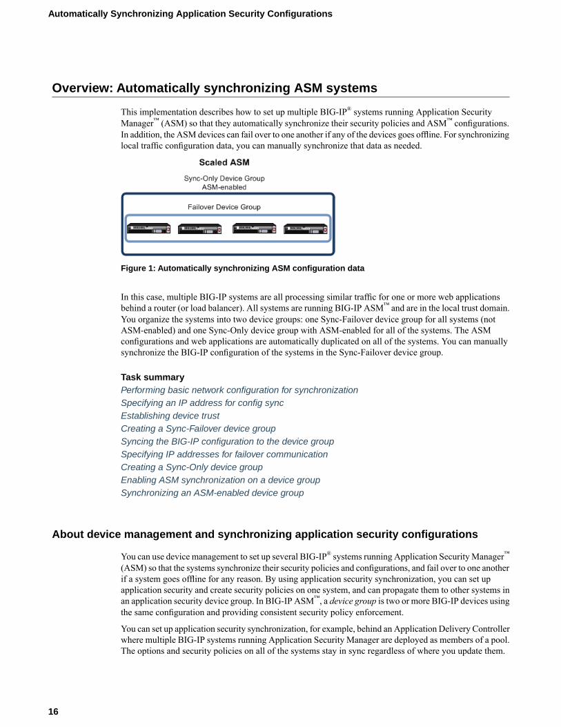
This implementation describes how to set up multiple BIG-IP® systems running Application SecurityManager™ (ASM) so that they automatically synchronize their security policies and ASM™ configurations.In addition, the ASM devices can fail over to one another if any of the devices goes offline. For synchronizinglocal traffic configuration data, you can manually synchronize that data as needed.
Figure 1: Automatically synchronizing ASM configuration data
In this case, multiple BIG-IP systems are all processing similar traffic for one or more web applicationsbehind a router (or load balancer). All systems are running BIG-IP ASM™ and are in the local trust domain.You organize the systems into two device groups: one Sync-Failover device group for all systems (notASM-enabled) and one Sync-Only device group with ASM-enabled for all of the systems. The ASMconfigurations and web applications are automatically duplicated on all of the systems. You can manuallysynchronize the BIG-IP configuration of the systems in the Sync-Failover device group.
Task summaryPerforming basic network configuration for synchronizationSpecifying an IP address for config syncEstablishing device trustCreating a Sync-Failover device groupSyncing the BIG-IP configuration to the device groupSpecifying IP addresses for failover communicationCreating a Sync-Only device groupEnabling ASM synchronization on a device groupSynchronizing an ASM-enabled device group
About device management and synchronizing application security configurations
You can use device management to set up several BIG-IP® systems running Application SecurityManager™
(ASM) so that the systems synchronize their security policies and configurations, and fail over to one anotherif a system goes offline for any reason. By using application security synchronization, you can set upapplication security and create security policies on one system, and can propagate them to other systems inan application security device group. In BIG-IP ASM™, a device group is two or more BIG-IP devices usingthe same configuration and providing consistent security policy enforcement.
You can set up application security synchronization, for example, behind an Application Delivery Controllerwhere multiple BIG-IP systems running Application Security Manager are deployed as members of a pool.The options and security policies on all of the systems stay in sync regardless of where you update them.
16
Automatically Synchronizing Application Security Configurations

When you set up ASM™ synchronization, in addition to security policies, other settings such as customattack signatures, logging profiles, SMTP configuration, anti-virus protection, system variables, and policytemplates, are synchronized with all devices in the ASM-enabled device group.
Considerations for application security synchronization
When using device management with Application Security Manager™ (ASM™), you need to be aware ofthe following considerations that apply specifically to application security synchronization.
• A BIG-IP® system with Application Security Manager can be a member of only one ASM-enableddevice group.
• All BIG-IP systems in a device group must be running the same version (including hot fix updates) ofApplication Security Manager (version 11.0 or later).
• The BIG-IP systems in the ASM-enabled device group synchronize application security configurationdata and security policies, providing consistent enforcement on all the devices.
• Real Traffic Policy Builder® can run on only one system per security policy. For example, you can setup automatic security policy building on one system that is a member of an ASM-enabled device group,the policy is built on that system and then automatically updated on all of the systems in the devicegroup.
• If using a VIPRION® platform (with multiple blades), it is considered one device, and you need to addonly the master blade to the device trust and group.
Performing basic network configuration for synchronization
You need to perform basic networking configuration for each of the BIG-IP® systems whose ApplicationSecurity Manager™ (ASM) configurations you want to synchronize.
1. Install the same BIG-IP system version (including any hot fixes) on each device.2. Provision LTM® and ASM™ on each device (System > Resource Provisioning).3. On each device, create one or more VLANs, depending on your networking configuration (Network >
VLANs).4. On each device, create a self IP (Network > Self IPs).
When creating the self IP, set Traffic Group to traffic-group-local-only (non-floating).
5. On each device, create a default gateway, if needed (Network > Routes).6. On each device, configure DNS (System > Configuration > Device > DNS) and NTP (System >
Configuration > Device > NTP) so they are set to the same time.7. Verify connectivity between the devices (self IP address to self IP address). For example, use this
command to ensure communications: ping -I vlan_interface device_self_IP
8. On each device, specify the IP address to use when synchronizing configuration objects to the localdevice:a) Click Device Management > Devices.b) Click the name of the local device.c) From the Device Connectivity menu, choose ConfigSync.d) For the Local Address setting, select the self IP address.e) Click Update.
9. If your company requires special device certificates, install them on each device (System > DeviceCertificates and click Import).
17
BIG-IP® Application Security Manager™: Implementations
The basic networking setup is complete for the BIG-IP ASM systems for which you want to share securitypolicies and configurations.
Specifying an IP address for config sync
Before configuring the config sync address, verify that all devices in the device group are running the sameversion of BIG-IP® system software.
You perform this task to specify the IP address on the local device that other devices in the device groupwill use to synchronize their configuration objects to the local device.
Note: You must perform this task locally on each device in the device group.
1. Confirm that you are logged in to the actual device you want to configure.2. On the Main tab, click Device Management > Devices.
This displays a list of device objects discovered by the local device.3. In the Name column, click the name of the device to which you are currently logged in.4. From the Device Connectivity menu, choose ConfigSync.5. For the Local Address setting, retain the displayed IP address or select another address from the list.
F5 Networks recommends that you use the default value, which is the self IP address for VLANinternal. This address must be a non-floating self IP address and not a management IP address.
Important: If the BIG-IP device you are configuring is accessed using Amazon Web Services, then theinternal self IP address that you specify must be the internal private IP addresses that you configuredfor this EC2 instance as the Local Address.
6. Click Update.
After performing this task, the other devices in the device group can sync their configurations to the localdevice.
Establishing device trust
Before you begin this task, verify that:
• Each BIG-IP® device that is to be part of the local trust domain has a device certificate installed on it.• The local device is designated as a certificate signing authority.
You perform this task to establish trust among devices on one or more network segments. Devices that trusteach other constitute the local trust domain. A device must be a member of the local trust domain prior tojoining a device group.
By default, the BIG-IP software includes a local trust domain with one member, which is the local device.You can choose any one of the BIG-IP devices slated for a device group and log into that device to addother devices to the local trust domain. For example, devices A, B, and C each initially shows only itself asa member of the local trust domain. To configure the local trust domain to include all three devices, youcan simply log into device A and add devices B and C to the local trust domain. Note that there is no needto repeat this process on devices B and C.
1. On the Main tab, clickDevice Management >Device Trust, and then either Peer List or SubordinateList.
2. Click Add.
18
Automatically Synchronizing Application Security Configurations
3. Type a device IP address, administrator user name, and administrator password for the remote BIG-IP®
device with which you want to establish trust. The IP address you specify depends on the type of BIG-IPdevice:
• If the BIG-IP device is a non-VIPRION device, type the management IP address for the device.• If the BIG-IP device is a VIPRION device that is not licensed and provisioned for vCMP, type the
primary cluster management IP address for the cluster.• If the BIG-IP device is a VIPRION device that is licensed and provisioned for vCMP, type the cluster
management IP address for the guest.• If the BIG-IP device is an Amazon Web Services EC2 device, type one of the Private IP addresses
created for this EC2 instance.
4. Click Retrieve Device Information.5. Verify that the certificate of the remote device is correct.6. Verify that the name of the remote device is correct.7. Verify that the management IP address and name of the remote device are correct.8. Click Finished.
The device you added is now a member of the local trust domain.
Repeat this task for each device that you want to add to the local trust domain.
Creating a Sync-Failover device group
This task establishes failover capability between two or more BIG-IP® devices. If an active device in aSync-Failover device group becomes unavailable, the configuration objects fail over to another member ofthe device group and traffic processing is unaffected. You perform this task on any one of the authoritydevices within the local trust domain.
Repeat this task for each Sync-Failover device group that you want to create for your network configuration.
1. On the Main tab, click Device Management > Device Groups.2. On the Device Groups list screen, click Create.
The New Device Group screen opens.3. Type a name for the device group, select the device group type Sync-Failover, and type a description
for the device group.4. From the Configuration list, select Advanced.5. In the Configuration area of the screen, select a host name from theAvailable list for each BIG-IP device
that you want to include in the device group, including the local device. Use the Move button to movethe host name to the Includes list.TheAvailable list shows any devices that are members of the device's local trust domain but not currentlymembers of a Sync-Failover device group. A device can be a member of one Sync-Failover group only.
6. For the Network Failover setting, select or clear the check box:
• Select the check box if you want device group members to handle failover communications by wayof network connectivity.
• Clear the check box if you want device group members to handle failover communications by wayof serial cable (hard-wired) connectivity.
You must enable network failover for any device group that contains three or more members.
7. For the Automatic Sync setting, select or clear the check box:
19
BIG-IP® Application Security Manager™: Implementations
• Select the check boxwhen youwant the BIG-IP system to automatically sync the BIG-IP configurationdata whenever a config sync operation is required. In this case, the BIG-IP system syncs theconfiguration data whenever the data changes on any device in the device group.
• Clear the check box when you want to manually initiate each config sync operation. In this case, F5networks recommends that you perform a config sync operation whenever configuration data changeson one of the devices in the device group.
8. For the Full Sync setting, select or clear the check box:
• Select the check box when you want all sync operations to be full syncs. In this case, the BIG-IPsystem syncs the entire set of BIG-IP configuration data whenever a config sync operation is required.
• Clear the check box when you want all sync operations to be incremental (the default setting). Inthis case, the BIG-IP system syncs only the changes that are more recent than those on the targetdevice. When you select this option, the BIG-IP system compares the configuration data on eachtarget device with the configuration data on the source device and then syncs the delta of eachtarget-source pair.
If you enable incremental synchronization, the BIG-IP system might occasionally perform a full syncfor internal reasons. This is a rare occurrence and no user intervention is required.
9. In theMaximum Incremental Sync Size (KB) field, retain the default value of 1024, or type a differentvalue.This value specifies the total size of configuration changes that can reside in the incremental sync cache.If the total size of the configuration changes in the cache exceeds the specified value, the BIG-IP systemperforms a full sync whenever the next config sync operation occurs.
10. Click Finished.
You now have a Sync-Failover type of device group containing BIG-IP devices as members.
Syncing the BIG-IP configuration to the device group
Before you sync the configuration, verify that the devices targeted for config sync are members of a devicegroup and that device trust is established.
This task synchronizes the BIG-IP® configuration data from the local device to the devices in the devicegroup. This synchronization ensures that devices in the device group operate properly. When synchronizingself IP addresses, the BIG-IP system synchronizes floating self IP addresses only.
Important: You perform this task on either of the two devices, but not both.
1. On the Main tab, click Device Management > Overview.2. In the Device Groups area of the screen, in the Name column, select the name of the relevant device
group.The screen expands to show a summary and details of the sync status of the selected device group, aswell as a list of the individual devices within the device group.
3. In the Devices area of the screen, in the Sync Status column, select the device that shows a sync statusof Changes Pending.
4. In the Sync Options area of the screen, select Sync Device to Group.5. Click Sync.
The BIG-IP system syncs the configuration data of the selected device in the Device area of the screento the other members of the device group.
Except for non-floating self IP addresses, the entire set of BIG-IP configuration data is replicated on eachdevice in the device group.
20
Automatically Synchronizing Application Security Configurations
Specifying IP addresses for failover communication
You typically perform this task during initial Device Service Clustering (DSC®) configuration, to specifythe local IP addresses that you want other devices in the device group to use for continuous health-assessmentcommunication with the local device. Youmust perform this task locally on each device in the device group.
Note: The IP addresses that you specify must belong to route domain 0.
1. Confirm that you are logged in to the actual device you want to configure.2. On the Main tab, click Device Management > Devices.
This displays a list of device objects discovered by the local device.3. In the Name column, click the name of the device to which you are currently logged in.4. From the Device Connectivity menu, choose Failover.5. For the Failover Unicast Configuration settings, click Add for each IP address on this device that other
devices in the device group can use to exchange failover messages with this device. The unicast IPaddresses you specify depend on the type of device:
ActionPlatform
Type a self IP address associated with an internal VLAN (preferably VLAN HA) andthe management IP address for the device.
Non-VIPRION
Type the self IP address for an internal VLAN (preferably VLAN HA) and themanagement IP addresses for all slots in the VIPRION cluster. Note that if you also
VIPRIONwithoutvCMP configure a multicast address (using the Use Failover Multicast Address setting),
then these management IP addresses are not required.
Type a self IP address that is defined on the guest and associated with an internal VLANon the host (preferably VLAN HA). Youmust also specify the management IP addresses
VIPRIONwith vCMP
for all of the slots configured for the guest. Note that if you also configure a multicastaddress (using the Use Failover Multicast Address setting), then these managementIP addresses are not required.
6. To enable the use of a failover multicast address on a VIPRION® platform (recommended), then for theUse Failover Multicast Address setting, select the Enabled check box.
7. If you enabled Use Failover Multicast Address, either accept the default Address and Port values, orspecify values appropriate for the device.If you revise the default Address and Port values, but then decide to revert to the default values, clickReset Defaults.
8. Click Update.
After you perform this task, other devices in the device group can send failover messages to the local deviceusing the specified IP addresses.
Creating a Sync-Only device group
You perform this task to create a Sync-Only type of device group. When you create a Sync-Only devicegroup, the BIG-IP® system can then automatically synchronize certain types of data such as security policiesand acceleration applications and policies to the other devices in the group, even when some of those devicesreside in another network. You can perform this task on any BIG-IP device within the local trust domain.
1. On the Main tab, click Device Management > Device Groups.
21
BIG-IP® Application Security Manager™: Implementations
2. On the Device Groups list screen, click Create.The New Device Group screen opens.
3. Type a name for the device group, select the device group type Sync-Only, and type a description forthe device group.
4. From the Configuration list, select Advanced.5. For theMembers setting, select an IP address and host name from the Available list for each BIG-IP
device that you want to include in the device group. Use the Move button to move the host name to theIncludes list.The list shows any devices that are members of the device's local trust domain.
6. For the Automatic Sync setting, select or clear the check box:
• Select the check boxwhen youwant the BIG-IP system to automatically sync the BIG-IP configurationdata whenever a config sync operation is required. In this case, the BIG-IP system syncs theconfiguration data whenever the data changes on any device in the device group.
• Clear the check box when you want to manually initiate each config sync operation. In this case, F5networks recommends that you perform a config sync operation whenever configuration data changeson one of the devices in the device group.
7. For the Full Sync setting, select or clear the check box:
• Select the check box when you want all sync operations to be full syncs. In this case, the BIG-IPsystem syncs the entire set of BIG-IP configuration data whenever a config sync operation is required.
• Clear the check box when you want all sync operations to be incremental (the default setting). Inthis case, the BIG-IP system syncs only the changes that are more recent than those on the targetdevice. When you select this option, the BIG-IP system compares the configuration data on eachtarget device with the configuration data on the source device and then syncs the delta of eachtarget-source pair.
If you enable incremental synchronization, the BIG-IP system might occasionally perform a full syncfor internal reasons. This is a rare occurrence and no user intervention is required.
8. In theMaximum Incremental Sync Size (KB) field, retain the default value of 1024, or type a differentvalue.This value specifies the total size of configuration changes that can reside in the incremental sync cache.If the total size of the configuration changes in the cache exceeds the specified value, the BIG-IP systemperforms a full sync whenever the next config sync operation occurs.
9. Click Finished.
You now have a Sync-Only type of device group containing BIG-IP devices as members.
Enabling ASM synchronization on a device group
You need to have already set up the BIG-IP®systems you want to synchronize in a device trust and a devicegroup. Application Security Manager™ (ASM) must be provisioned on all the systems in the device group.
You can enable ASM™ synchronization on a device group to synchronize security policies and configurationson all devices in the device group. You do this task on one system; for example, the active system in anactive-standby pair.
1. On the Main tab, click Security > Application Security > Synchronization.The system displays a list of device groups of which this device is a member.
2. For Device Group, select the device group whose members you want to synchronize.3. Click Save.
22
Automatically Synchronizing Application Security Configurations

The BIG-IP ASM systems that you want to share security policies and configurations are part of a devicegroup with ASM synchronization.
Synchronizing an ASM-enabled device group
You need to have set up the BIG-IP®Application SecurityManager™ (ASM) systems youwant to synchronizein a Sync-Failover device group that is ASM™-enabled.
You can manually synchronize security policies and configuration of systems in an ASM-enabled devicegroup.
1. On one system in the ASM-enabled failover device group, create an application security policy.Because the two systems are not in sync, you see a Changes Pending status message on the screen.
2. Click the Changes Pending message.
Tip: You can also click Device Management > Overview.
The Overview screen opens.3. In the Device Groups area of the screen, in the Name column, select the name of the relevant device
group.The screen expands to show a summary and details of the sync status of the selected device group, aswell as a list of the individual devices within the device group.
4. In the Devices area of the screen, in the Sync Status column, select the device that shows a sync statusof Changes Pending.
5. In the Sync Options area of the screen, select Sync Device to Group.6. Click Sync.
The BIG-IP system syncs the configuration data of the selected device in the Device area of the screento the other members of the device group.
7. Verify that the devices are synchronized.For example, log in to another device in the device group and verify that the security policy you createdalso resides on that system. Click Security > Application Security > Security Policies and see if thepolicy is listed.
Except for static self IP addresses, the entire set of BIG-IP configuration data including ASM™ securitypolicies and configuration is replicated on one or more devices in the ASM-enabled device group. If theactive device is not available, the standby device becomes active and handles traffic.
You can create new security policies or update existing ones on any of the devices in the group, or updatethe ASM configuration options. You can manually synchronize changes you make on one device with theother devices in the ASM-enabled device group.
Implementation result
You have set up multiple BIG-IP® systems running Application Security Manager™ (ASM) so that theyautomatically synchronize their ASM security policies and ASM configuration data. In addition, with thisimplementation, you can manually synchronize the local traffic configuration, as needed.
You can create new security policies or update existing ones on any of the devices in the group, or updatethe ASM™ configuration options. AnyASM changes youmake on one device are automatically synchronizedwith the other devices in the ASM-enabled Sync-Only device group.
23
BIG-IP® Application Security Manager™: Implementations

If Attack Signatures Update Mode is scheduled for automatic update, the attack signature update settingsare synchronized. Each device in the device group updates itself independently according to the configuredschedule. If you manually upload attack signatures or click Update Signatures to update from the server,the update is propagated to all of the devices in the device group.
24
Automatically Synchronizing Application Security Configurations
Chapter
2Manually Synchronizing Application Security Configurations
• Overview: Manually synchronizing ASMsystems
• Implementation result
Overview: Manually synchronizing ASM systems
This implementation describes how to set up two BIG-IP® systems running Application Security Manager™
(ASM) so that you can synchronize their security policies and configurations. With this implementation,the BIG-IP systems can fail over to one another, and you can manually sync all of the BIG-IP configurationdata, including ASM policy data.
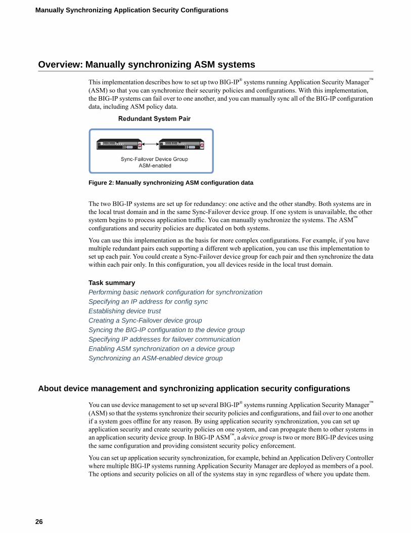
Figure 2: Manually synchronizing ASM configuration data
The two BIG-IP systems are set up for redundancy: one active and the other standby. Both systems are inthe local trust domain and in the same Sync-Failover device group. If one system is unavailable, the othersystem begins to process application traffic. You can manually synchronize the systems. The ASM™
configurations and security policies are duplicated on both systems.
You can use this implementation as the basis for more complex configurations. For example, if you havemultiple redundant pairs each supporting a different web application, you can use this implementation toset up each pair. You could create a Sync-Failover device group for each pair and then synchronize the datawithin each pair only. In this configuration, you all devices reside in the local trust domain.
Task summaryPerforming basic network configuration for synchronizationSpecifying an IP address for config syncEstablishing device trustCreating a Sync-Failover device groupSyncing the BIG-IP configuration to the device groupSpecifying IP addresses for failover communicationEnabling ASM synchronization on a device groupSynchronizing an ASM-enabled device group
About device management and synchronizing application security configurations
You can use device management to set up several BIG-IP® systems running Application SecurityManager™
(ASM) so that the systems synchronize their security policies and configurations, and fail over to one anotherif a system goes offline for any reason. By using application security synchronization, you can set upapplication security and create security policies on one system, and can propagate them to other systems inan application security device group. In BIG-IP ASM™, a device group is two or more BIG-IP devices usingthe same configuration and providing consistent security policy enforcement.
You can set up application security synchronization, for example, behind an Application Delivery Controllerwhere multiple BIG-IP systems running Application Security Manager are deployed as members of a pool.The options and security policies on all of the systems stay in sync regardless of where you update them.
26
Manually Synchronizing Application Security Configurations
When you set up ASM™ synchronization, in addition to security policies, other settings such as customattack signatures, logging profiles, SMTP configuration, anti-virus protection, system variables, and policytemplates, are synchronized with all devices in the ASM-enabled device group.
Considerations for application security synchronization
When using device management with Application Security Manager™ (ASM™), you need to be aware ofthe following considerations that apply specifically to application security synchronization.
• A BIG-IP® system with Application Security Manager can be a member of only one ASM-enableddevice group.
• All BIG-IP systems in a device group must be running the same version (including hot fix updates) ofApplication Security Manager (version 11.0 or later).
• The BIG-IP systems in the ASM-enabled device group synchronize application security configurationdata and security policies, providing consistent enforcement on all the devices.
• Real Traffic Policy Builder® can run on only one system per security policy. For example, you can setup automatic security policy building on one system that is a member of an ASM-enabled device group,the policy is built on that system and then automatically updated on all of the systems in the devicegroup.
• If using a VIPRION® platform (with multiple blades), it is considered one device, and you need to addonly the master blade to the device trust and group.
Performing basic network configuration for synchronization
You need to perform basic networking configuration for each of the BIG-IP® systems whose ApplicationSecurity Manager™ (ASM) configurations you want to synchronize.
1. Install the same BIG-IP system version (including any hot fixes) on each device.2. Provision LTM® and ASM™ on each device (System > Resource Provisioning).3. On each device, create one or more VLANs, depending on your networking configuration (Network >
VLANs).4. On each device, create a self IP (Network > Self IPs).
When creating the self IP, set Traffic Group to traffic-group-local-only (non-floating).
5. On each device, create a default gateway, if needed (Network > Routes).6. On each device, configure DNS (System > Configuration > Device > DNS) and NTP (System >
Configuration > Device > NTP) so they are set to the same time.7. Verify connectivity between the devices (self IP address to self IP address). For example, use this
command to ensure communications: ping -I vlan_interface device_self_IP
8. On each device, specify the IP address to use when synchronizing configuration objects to the localdevice:a) Click Device Management > Devices.b) Click the name of the local device.c) From the Device Connectivity menu, choose ConfigSync.d) For the Local Address setting, select the self IP address.e) Click Update.
9. If your company requires special device certificates, install them on each device (System > DeviceCertificates and click Import).
27
BIG-IP® Application Security Manager™: Implementations

The basic networking setup is complete for the BIG-IP ASM systems for which you want to share securitypolicies and configurations.
Specifying an IP address for config sync
Before configuring the config sync address, verify that all devices in the device group are running the sameversion of BIG-IP® system software.
You perform this task to specify the IP address on the local device that other devices in the device groupwill use to synchronize their configuration objects to the local device.
Note: You must perform this task locally on each device in the device group.
1. Confirm that you are logged in to the actual device you want to configure.2. On the Main tab, click Device Management > Devices.
This displays a list of device objects discovered by the local device.3. In the Name column, click the name of the device to which you are currently logged in.4. From the Device Connectivity menu, choose ConfigSync.5. For the Local Address setting, retain the displayed IP address or select another address from the list.
F5 Networks recommends that you use the default value, which is the self IP address for VLANinternal. This address must be a non-floating self IP address and not a management IP address.
Important: If the BIG-IP device you are configuring is accessed using Amazon Web Services, then theinternal self IP address that you specify must be the internal private IP addresses that you configuredfor this EC2 instance as the Local Address.
6. Click Update.
After performing this task, the other devices in the device group can sync their configurations to the localdevice.
Establishing device trust
Before you begin this task, verify that:
• Each BIG-IP® device that is to be part of the local trust domain has a device certificate installed on it.• The local device is designated as a certificate signing authority.
You perform this task to establish trust among devices on one or more network segments. Devices that trusteach other constitute the local trust domain. A device must be a member of the local trust domain prior tojoining a device group.
By default, the BIG-IP software includes a local trust domain with one member, which is the local device.You can choose any one of the BIG-IP devices slated for a device group and log into that device to addother devices to the local trust domain. For example, devices A, B, and C each initially shows only itself asa member of the local trust domain. To configure the local trust domain to include all three devices, youcan simply log into device A and add devices B and C to the local trust domain. Note that there is no needto repeat this process on devices B and C.
1. On the Main tab, clickDevice Management >Device Trust, and then either Peer List or SubordinateList.
2. Click Add.
28
Manually Synchronizing Application Security Configurations

3. Type a device IP address, administrator user name, and administrator password for the remote BIG-IP®
device with which you want to establish trust. The IP address you specify depends on the type of BIG-IPdevice:
• If the BIG-IP device is a non-VIPRION device, type the management IP address for the device.• If the BIG-IP device is a VIPRION device that is not licensed and provisioned for vCMP, type the
primary cluster management IP address for the cluster.• If the BIG-IP device is a VIPRION device that is licensed and provisioned for vCMP, type the cluster
management IP address for the guest.• If the BIG-IP device is an Amazon Web Services EC2 device, type one of the Private IP addresses
created for this EC2 instance.
4. Click Retrieve Device Information.5. Verify that the certificate of the remote device is correct.6. Verify that the name of the remote device is correct.7. Verify that the management IP address and name of the remote device are correct.8. Click Finished.
The device you added is now a member of the local trust domain.
Repeat this task for each device that you want to add to the local trust domain.
Creating a Sync-Failover device group
This task establishes failover capability between two or more BIG-IP® devices. If an active device in aSync-Failover device group becomes unavailable, the configuration objects fail over to another member ofthe device group and traffic processing is unaffected. You perform this task on any one of the authoritydevices within the local trust domain.
Repeat this task for each Sync-Failover device group that you want to create for your network configuration.
1. On the Main tab, click Device Management > Device Groups.2. On the Device Groups list screen, click Create.
The New Device Group screen opens.3. Type a name for the device group, select the device group type Sync-Failover, and type a description
for the device group.4. From the Configuration list, select Advanced.5. In the Configuration area of the screen, select a host name from theAvailable list for each BIG-IP device
that you want to include in the device group, including the local device. Use the Move button to movethe host name to the Includes list.TheAvailable list shows any devices that are members of the device's local trust domain but not currentlymembers of a Sync-Failover device group. A device can be a member of one Sync-Failover group only.
6. For the Network Failover setting, select or clear the check box:
• Select the check box if you want device group members to handle failover communications by wayof network connectivity.
• Clear the check box if you want device group members to handle failover communications by wayof serial cable (hard-wired) connectivity.
You must enable network failover for any device group that contains three or more members.
7. For the Automatic Sync setting, select or clear the check box:
29
BIG-IP® Application Security Manager™: Implementations

• Select the check boxwhen youwant the BIG-IP system to automatically sync the BIG-IP configurationdata whenever a config sync operation is required. In this case, the BIG-IP system syncs theconfiguration data whenever the data changes on any device in the device group.
• Clear the check box when you want to manually initiate each config sync operation. In this case, F5networks recommends that you perform a config sync operation whenever configuration data changeson one of the devices in the device group.
8. For the Full Sync setting, select or clear the check box:
• Select the check box when you want all sync operations to be full syncs. In this case, the BIG-IPsystem syncs the entire set of BIG-IP configuration data whenever a config sync operation is required.
• Clear the check box when you want all sync operations to be incremental (the default setting). Inthis case, the BIG-IP system syncs only the changes that are more recent than those on the targetdevice. When you select this option, the BIG-IP system compares the configuration data on eachtarget device with the configuration data on the source device and then syncs the delta of eachtarget-source pair.
If you enable incremental synchronization, the BIG-IP system might occasionally perform a full syncfor internal reasons. This is a rare occurrence and no user intervention is required.
9. In theMaximum Incremental Sync Size (KB) field, retain the default value of 1024, or type a differentvalue.This value specifies the total size of configuration changes that can reside in the incremental sync cache.If the total size of the configuration changes in the cache exceeds the specified value, the BIG-IP systemperforms a full sync whenever the next config sync operation occurs.
10. Click Finished.
You now have a Sync-Failover type of device group containing BIG-IP devices as members.
Syncing the BIG-IP configuration to the device group
Before you sync the configuration, verify that the devices targeted for config sync are members of a devicegroup and that device trust is established.
This task synchronizes the BIG-IP® configuration data from the local device to the devices in the devicegroup. This synchronization ensures that devices in the device group operate properly. When synchronizingself IP addresses, the BIG-IP system synchronizes floating self IP addresses only.
Important: You perform this task on either of the two devices, but not both.
1. On the Main tab, click Device Management > Overview.2. In the Device Groups area of the screen, in the Name column, select the name of the relevant device
group.The screen expands to show a summary and details of the sync status of the selected device group, aswell as a list of the individual devices within the device group.
3. In the Devices area of the screen, in the Sync Status column, select the device that shows a sync statusof Changes Pending.
4. In the Sync Options area of the screen, select Sync Device to Group.5. Click Sync.
The BIG-IP system syncs the configuration data of the selected device in the Device area of the screento the other members of the device group.
Except for non-floating self IP addresses, the entire set of BIG-IP configuration data is replicated on eachdevice in the device group.
30
Manually Synchronizing Application Security Configurations
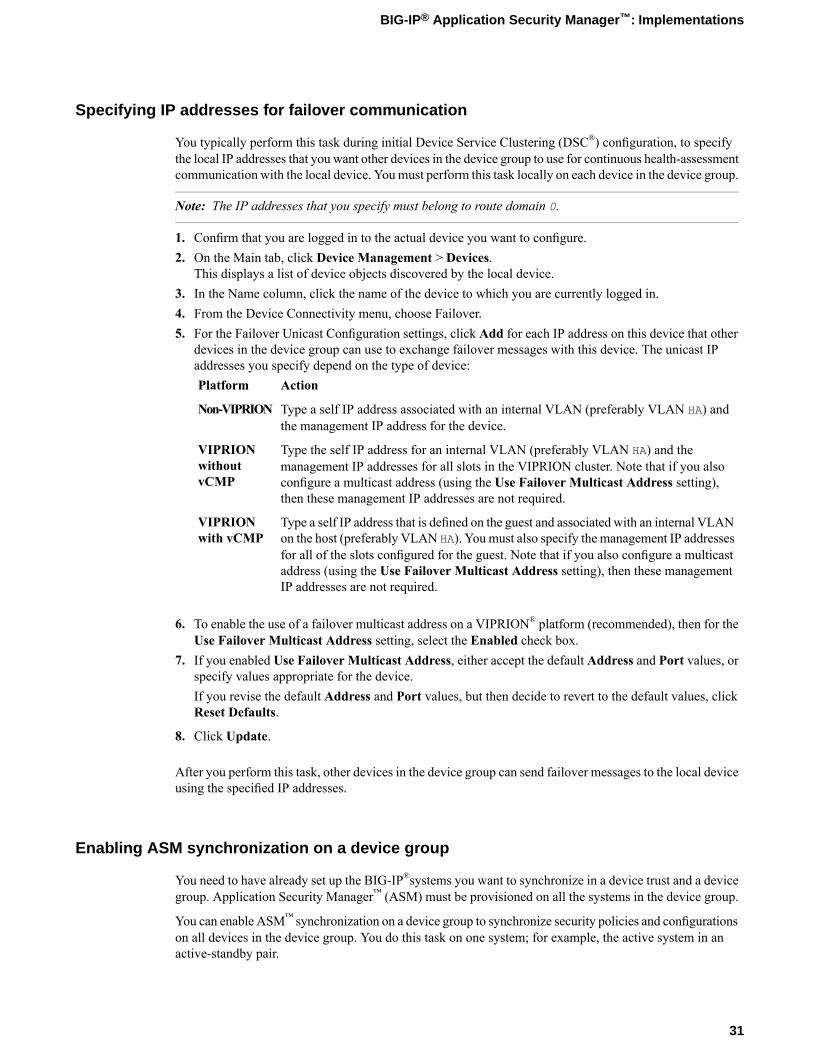
Specifying IP addresses for failover communication
You typically perform this task during initial Device Service Clustering (DSC®) configuration, to specifythe local IP addresses that you want other devices in the device group to use for continuous health-assessmentcommunication with the local device. Youmust perform this task locally on each device in the device group.
Note: The IP addresses that you specify must belong to route domain 0.
1. Confirm that you are logged in to the actual device you want to configure.2. On the Main tab, click Device Management > Devices.
This displays a list of device objects discovered by the local device.3. In the Name column, click the name of the device to which you are currently logged in.4. From the Device Connectivity menu, choose Failover.5. For the Failover Unicast Configuration settings, click Add for each IP address on this device that other
devices in the device group can use to exchange failover messages with this device. The unicast IPaddresses you specify depend on the type of device:
ActionPlatform
Type a self IP address associated with an internal VLAN (preferably VLAN HA) andthe management IP address for the device.
Non-VIPRION
Type the self IP address for an internal VLAN (preferably VLAN HA) and themanagement IP addresses for all slots in the VIPRION cluster. Note that if you also
VIPRIONwithoutvCMP configure a multicast address (using the Use Failover Multicast Address setting),
then these management IP addresses are not required.
Type a self IP address that is defined on the guest and associated with an internal VLANon the host (preferably VLAN HA). Youmust also specify the management IP addresses
VIPRIONwith vCMP
for all of the slots configured for the guest. Note that if you also configure a multicastaddress (using the Use Failover Multicast Address setting), then these managementIP addresses are not required.
6. To enable the use of a failover multicast address on a VIPRION® platform (recommended), then for theUse Failover Multicast Address setting, select the Enabled check box.
7. If you enabled Use Failover Multicast Address, either accept the default Address and Port values, orspecify values appropriate for the device.If you revise the default Address and Port values, but then decide to revert to the default values, clickReset Defaults.
8. Click Update.
After you perform this task, other devices in the device group can send failover messages to the local deviceusing the specified IP addresses.
Enabling ASM synchronization on a device group
You need to have already set up the BIG-IP®systems you want to synchronize in a device trust and a devicegroup. Application Security Manager™ (ASM) must be provisioned on all the systems in the device group.
You can enable ASM™ synchronization on a device group to synchronize security policies and configurationson all devices in the device group. You do this task on one system; for example, the active system in anactive-standby pair.
31
BIG-IP® Application Security Manager™: Implementations
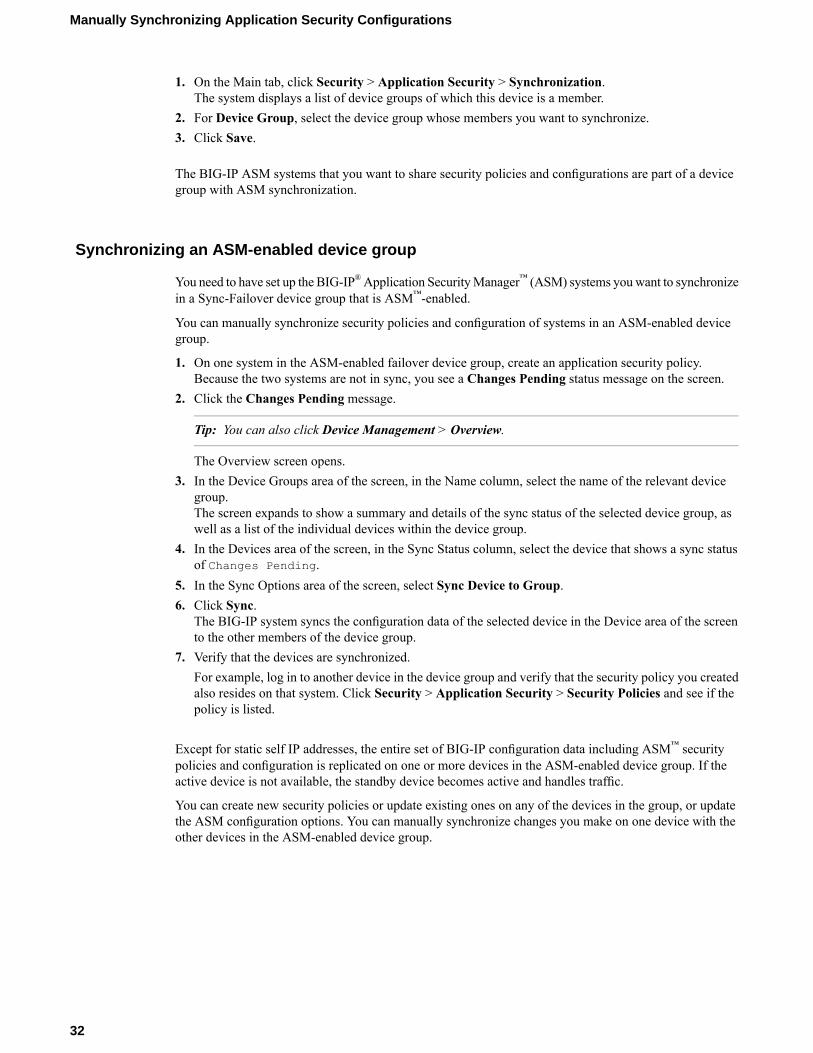
1. On the Main tab, click Security > Application Security > Synchronization.The system displays a list of device groups of which this device is a member.
2. For Device Group, select the device group whose members you want to synchronize.3. Click Save.
The BIG-IP ASM systems that you want to share security policies and configurations are part of a devicegroup with ASM synchronization.
Synchronizing an ASM-enabled device group
You need to have set up the BIG-IP®Application SecurityManager™ (ASM) systems youwant to synchronizein a Sync-Failover device group that is ASM™-enabled.
You can manually synchronize security policies and configuration of systems in an ASM-enabled devicegroup.
1. On one system in the ASM-enabled failover device group, create an application security policy.Because the two systems are not in sync, you see a Changes Pending status message on the screen.
2. Click the Changes Pending message.
Tip: You can also click Device Management > Overview.
The Overview screen opens.3. In the Device Groups area of the screen, in the Name column, select the name of the relevant device
group.The screen expands to show a summary and details of the sync status of the selected device group, aswell as a list of the individual devices within the device group.
4. In the Devices area of the screen, in the Sync Status column, select the device that shows a sync statusof Changes Pending.
5. In the Sync Options area of the screen, select Sync Device to Group.6. Click Sync.
The BIG-IP system syncs the configuration data of the selected device in the Device area of the screento the other members of the device group.
7. Verify that the devices are synchronized.For example, log in to another device in the device group and verify that the security policy you createdalso resides on that system. Click Security > Application Security > Security Policies and see if thepolicy is listed.
Except for static self IP addresses, the entire set of BIG-IP configuration data including ASM™ securitypolicies and configuration is replicated on one or more devices in the ASM-enabled device group. If theactive device is not available, the standby device becomes active and handles traffic.
You can create new security policies or update existing ones on any of the devices in the group, or updatethe ASM configuration options. You can manually synchronize changes you make on one device with theother devices in the ASM-enabled device group.
32
Manually Synchronizing Application Security Configurations
Implementation result
You have now set up two BIG-IP® systems running Application Security Manager™ (ASM) so that you cansynchronize their security policies and configurations.With this implementation, youmanually synchronizethe ASM and BIG-IP configurations.
The two BIG-IP systems are in the same Sync-Failover device group. If one system becomes unavailable,the other system begins processing application traffic.
33
BIG-IP® Application Security Manager™: Implementations

Chapter
3Synchronizing Application Security Configurations AcrossLANs
• Overview: Synchronizing ASM systemsacross LANs
• Implementation result

Overview: Synchronizing ASM systems across LANs
This implementation describes how to set up multiple BIG-IP® systems running Application SecurityManager™ (ASM) so that you can synchronize their security policies and configurations for disaster recovery.You can use this implementation to synchronize BIG-IP ASM™ security policies and configurations onsystems that reside in different network segments or LANs, such as those in separate offices or data centers.Note that traffic must be routable between the network segments. If a disaster occurs at one of the officesand both devices are disabled, the latest security policies are still available on the systems in the otherlocation.
This implementation also configures failover between systems in a redundant pair on a particular networksegment. If one of the devices in a pair goes offline for any reason, the other device in the pair beginsprocessing the application traffic.
Figure 3: Automatically synchronizing ASM configuration data across LANs
In the figure, two sets of BIG-IP systems are set up for redundancy: one active and the other standby. Eachpair is in a different network segment (LAN), and there can be additional pairs, as needed. Each LAN hasone pair of devices, where both have the same default routing, but routing is not the same for the devicesin the other LAN.
All of the systems are running ASM and are in the trust domain. Three device groups are set up: oneSync-Failover device group for each pair (not ASM-enabled), and one Sync-Only device group with ASMenabled using automatic synchronization for all of the systems. The systems automatically duplicate theASM configurations and security policies on all of the systems. You can manually synchronize the BIG-IPconfigurations of each pair of systems when needed.
Task summaryPerforming basic network configuration for synchronizationSpecifying an IP address for config syncEstablishing device trustCreating a Sync-Failover device groupSyncing the BIG-IP configuration to the device groupSpecifying IP addresses for failover communicationCreating a Sync-Only device groupEnabling ASM synchronization on a Sync-Only device groupSynchronizing an ASM-enabled device group
36
Synchronizing Application Security Configurations Across LANs
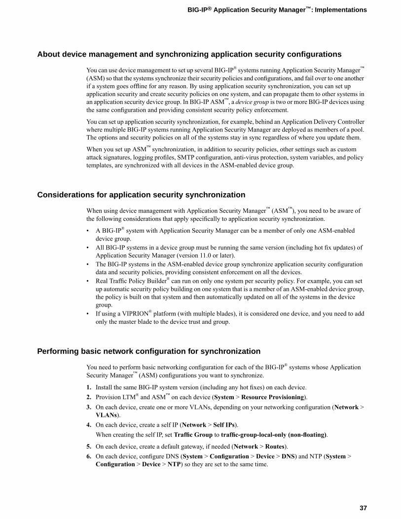
About device management and synchronizing application security configurations
You can use device management to set up several BIG-IP® systems running Application SecurityManager™
(ASM) so that the systems synchronize their security policies and configurations, and fail over to one anotherif a system goes offline for any reason. By using application security synchronization, you can set upapplication security and create security policies on one system, and can propagate them to other systems inan application security device group. In BIG-IP ASM™, a device group is two or more BIG-IP devices usingthe same configuration and providing consistent security policy enforcement.
You can set up application security synchronization, for example, behind an Application Delivery Controllerwhere multiple BIG-IP systems running Application Security Manager are deployed as members of a pool.The options and security policies on all of the systems stay in sync regardless of where you update them.
When you set up ASM™ synchronization, in addition to security policies, other settings such as customattack signatures, logging profiles, SMTP configuration, anti-virus protection, system variables, and policytemplates, are synchronized with all devices in the ASM-enabled device group.
Considerations for application security synchronization
When using device management with Application Security Manager™ (ASM™), you need to be aware ofthe following considerations that apply specifically to application security synchronization.
• A BIG-IP® system with Application Security Manager can be a member of only one ASM-enableddevice group.
• All BIG-IP systems in a device group must be running the same version (including hot fix updates) ofApplication Security Manager (version 11.0 or later).
• The BIG-IP systems in the ASM-enabled device group synchronize application security configurationdata and security policies, providing consistent enforcement on all the devices.
• Real Traffic Policy Builder® can run on only one system per security policy. For example, you can setup automatic security policy building on one system that is a member of an ASM-enabled device group,the policy is built on that system and then automatically updated on all of the systems in the devicegroup.
• If using a VIPRION® platform (with multiple blades), it is considered one device, and you need to addonly the master blade to the device trust and group.
Performing basic network configuration for synchronization
You need to perform basic networking configuration for each of the BIG-IP® systems whose ApplicationSecurity Manager™ (ASM) configurations you want to synchronize.
1. Install the same BIG-IP system version (including any hot fixes) on each device.2. Provision LTM® and ASM™ on each device (System > Resource Provisioning).3. On each device, create one or more VLANs, depending on your networking configuration (Network >
VLANs).4. On each device, create a self IP (Network > Self IPs).
When creating the self IP, set Traffic Group to traffic-group-local-only (non-floating).
5. On each device, create a default gateway, if needed (Network > Routes).6. On each device, configure DNS (System > Configuration > Device > DNS) and NTP (System >
Configuration > Device > NTP) so they are set to the same time.
37
BIG-IP® Application Security Manager™: Implementations
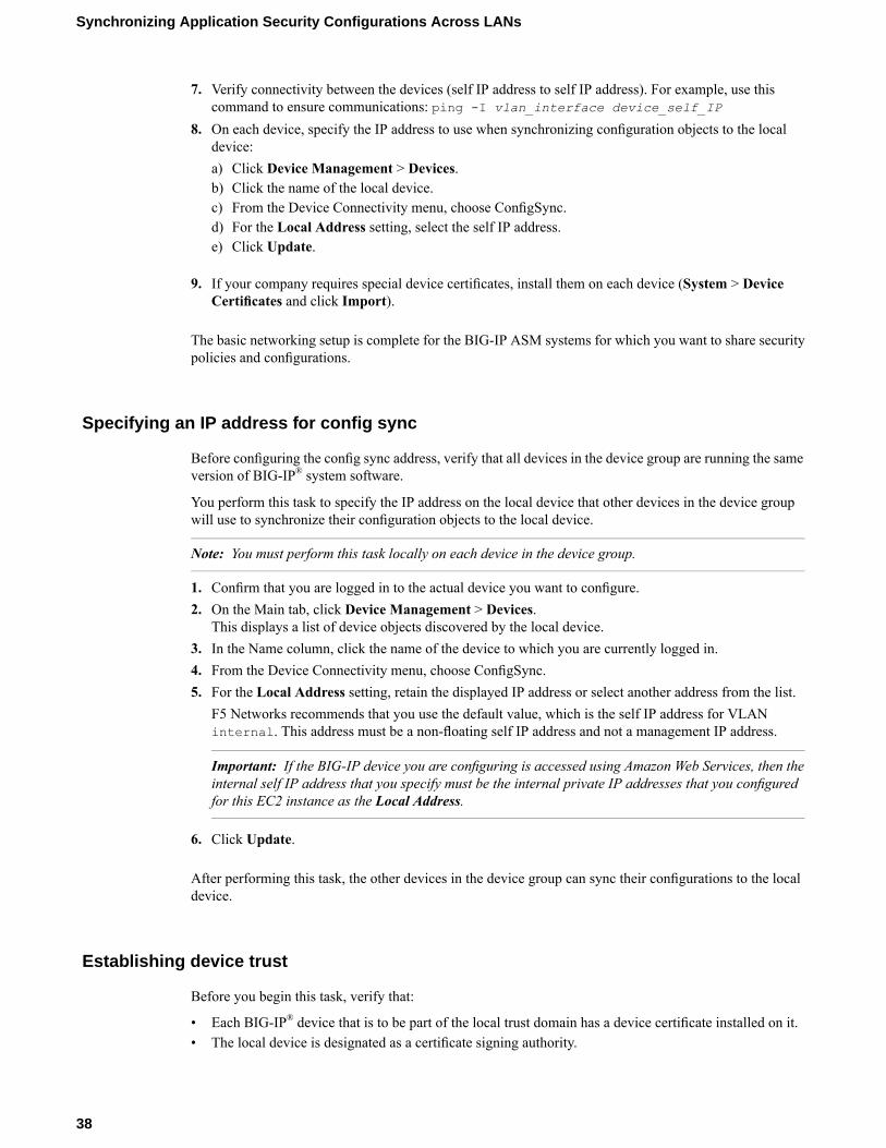
7. Verify connectivity between the devices (self IP address to self IP address). For example, use thiscommand to ensure communications: ping -I vlan_interface device_self_IP
8. On each device, specify the IP address to use when synchronizing configuration objects to the localdevice:a) Click Device Management > Devices.b) Click the name of the local device.c) From the Device Connectivity menu, choose ConfigSync.d) For the Local Address setting, select the self IP address.e) Click Update.
9. If your company requires special device certificates, install them on each device (System > DeviceCertificates and click Import).
The basic networking setup is complete for the BIG-IP ASM systems for which you want to share securitypolicies and configurations.
Specifying an IP address for config sync
Before configuring the config sync address, verify that all devices in the device group are running the sameversion of BIG-IP® system software.
You perform this task to specify the IP address on the local device that other devices in the device groupwill use to synchronize their configuration objects to the local device.
Note: You must perform this task locally on each device in the device group.
1. Confirm that you are logged in to the actual device you want to configure.2. On the Main tab, click Device Management > Devices.
This displays a list of device objects discovered by the local device.3. In the Name column, click the name of the device to which you are currently logged in.4. From the Device Connectivity menu, choose ConfigSync.5. For the Local Address setting, retain the displayed IP address or select another address from the list.
F5 Networks recommends that you use the default value, which is the self IP address for VLANinternal. This address must be a non-floating self IP address and not a management IP address.
Important: If the BIG-IP device you are configuring is accessed using Amazon Web Services, then theinternal self IP address that you specify must be the internal private IP addresses that you configuredfor this EC2 instance as the Local Address.
6. Click Update.
After performing this task, the other devices in the device group can sync their configurations to the localdevice.
Establishing device trust
Before you begin this task, verify that:
• Each BIG-IP® device that is to be part of the local trust domain has a device certificate installed on it.• The local device is designated as a certificate signing authority.
38
Synchronizing Application Security Configurations Across LANs
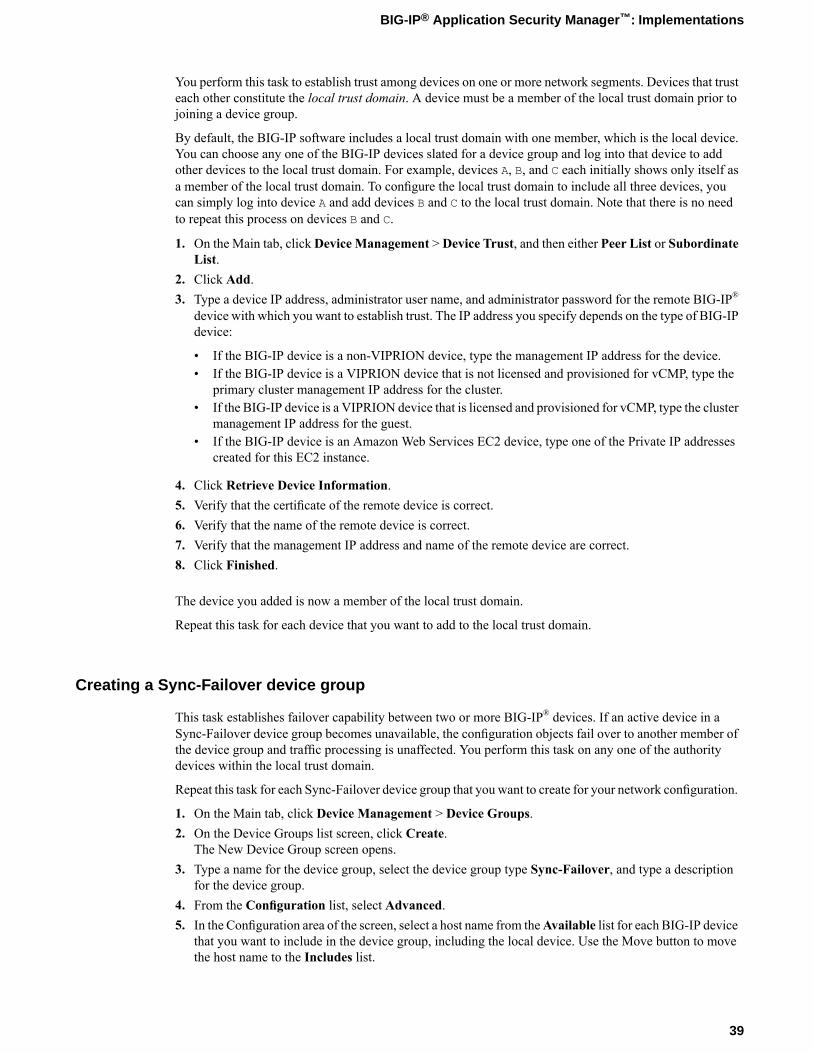
You perform this task to establish trust among devices on one or more network segments. Devices that trusteach other constitute the local trust domain. A device must be a member of the local trust domain prior tojoining a device group.
By default, the BIG-IP software includes a local trust domain with one member, which is the local device.You can choose any one of the BIG-IP devices slated for a device group and log into that device to addother devices to the local trust domain. For example, devices A, B, and C each initially shows only itself asa member of the local trust domain. To configure the local trust domain to include all three devices, youcan simply log into device A and add devices B and C to the local trust domain. Note that there is no needto repeat this process on devices B and C.
1. On the Main tab, clickDevice Management >Device Trust, and then either Peer List or SubordinateList.
2. Click Add.3. Type a device IP address, administrator user name, and administrator password for the remote BIG-IP®
device with which you want to establish trust. The IP address you specify depends on the type of BIG-IPdevice:
• If the BIG-IP device is a non-VIPRION device, type the management IP address for the device.• If the BIG-IP device is a VIPRION device that is not licensed and provisioned for vCMP, type the
primary cluster management IP address for the cluster.• If the BIG-IP device is a VIPRION device that is licensed and provisioned for vCMP, type the cluster
management IP address for the guest.• If the BIG-IP device is an Amazon Web Services EC2 device, type one of the Private IP addresses
created for this EC2 instance.
4. Click Retrieve Device Information.5. Verify that the certificate of the remote device is correct.6. Verify that the name of the remote device is correct.7. Verify that the management IP address and name of the remote device are correct.8. Click Finished.
The device you added is now a member of the local trust domain.
Repeat this task for each device that you want to add to the local trust domain.
Creating a Sync-Failover device group
This task establishes failover capability between two or more BIG-IP® devices. If an active device in aSync-Failover device group becomes unavailable, the configuration objects fail over to another member ofthe device group and traffic processing is unaffected. You perform this task on any one of the authoritydevices within the local trust domain.
Repeat this task for each Sync-Failover device group that you want to create for your network configuration.
1. On the Main tab, click Device Management > Device Groups.2. On the Device Groups list screen, click Create.
The New Device Group screen opens.3. Type a name for the device group, select the device group type Sync-Failover, and type a description
for the device group.4. From the Configuration list, select Advanced.5. In the Configuration area of the screen, select a host name from theAvailable list for each BIG-IP device
that you want to include in the device group, including the local device. Use the Move button to movethe host name to the Includes list.
39
BIG-IP® Application Security Manager™: Implementations

TheAvailable list shows any devices that are members of the device's local trust domain but not currentlymembers of a Sync-Failover device group. A device can be a member of one Sync-Failover group only.
6. For the Network Failover setting, select or clear the check box:
• Select the check box if you want device group members to handle failover communications by wayof network connectivity.
• Clear the check box if you want device group members to handle failover communications by wayof serial cable (hard-wired) connectivity.
You must enable network failover for any device group that contains three or more members.
7. For the Automatic Sync setting, select or clear the check box:
• Select the check boxwhen youwant the BIG-IP system to automatically sync the BIG-IP configurationdata whenever a config sync operation is required. In this case, the BIG-IP system syncs theconfiguration data whenever the data changes on any device in the device group.
• Clear the check box when you want to manually initiate each config sync operation. In this case, F5networks recommends that you perform a config sync operation whenever configuration data changeson one of the devices in the device group.
8. For the Full Sync setting, select or clear the check box:
• Select the check box when you want all sync operations to be full syncs. In this case, the BIG-IPsystem syncs the entire set of BIG-IP configuration data whenever a config sync operation is required.
• Clear the check box when you want all sync operations to be incremental (the default setting). Inthis case, the BIG-IP system syncs only the changes that are more recent than those on the targetdevice. When you select this option, the BIG-IP system compares the configuration data on eachtarget device with the configuration data on the source device and then syncs the delta of eachtarget-source pair.
If you enable incremental synchronization, the BIG-IP system might occasionally perform a full syncfor internal reasons. This is a rare occurrence and no user intervention is required.
9. In theMaximum Incremental Sync Size (KB) field, retain the default value of 1024, or type a differentvalue.This value specifies the total size of configuration changes that can reside in the incremental sync cache.If the total size of the configuration changes in the cache exceeds the specified value, the BIG-IP systemperforms a full sync whenever the next config sync operation occurs.
10. Click Finished.
You now have a Sync-Failover type of device group containing BIG-IP devices as members.
Syncing the BIG-IP configuration to the device group
Before you sync the configuration, verify that the devices targeted for config sync are members of a devicegroup and that device trust is established.
This task synchronizes the BIG-IP® configuration data from the local device to the devices in the devicegroup. This synchronization ensures that devices in the device group operate properly. When synchronizingself IP addresses, the BIG-IP system synchronizes floating self IP addresses only.
Important: You perform this task on either of the two devices, but not both.
1. On the Main tab, click Device Management > Overview.2. In the Device Groups area of the screen, in the Name column, select the name of the relevant device
group.
40
Synchronizing Application Security Configurations Across LANs
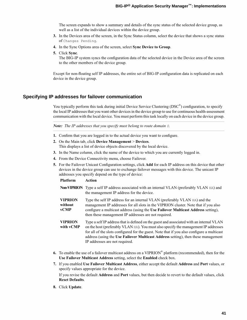
The screen expands to show a summary and details of the sync status of the selected device group, aswell as a list of the individual devices within the device group.
3. In the Devices area of the screen, in the Sync Status column, select the device that shows a sync statusof Changes Pending.
4. In the Sync Options area of the screen, select Sync Device to Group.5. Click Sync.
The BIG-IP system syncs the configuration data of the selected device in the Device area of the screento the other members of the device group.
Except for non-floating self IP addresses, the entire set of BIG-IP configuration data is replicated on eachdevice in the device group.
Specifying IP addresses for failover communication
You typically perform this task during initial Device Service Clustering (DSC®) configuration, to specifythe local IP addresses that you want other devices in the device group to use for continuous health-assessmentcommunication with the local device. Youmust perform this task locally on each device in the device group.
Note: The IP addresses that you specify must belong to route domain 0.
1. Confirm that you are logged in to the actual device you want to configure.2. On the Main tab, click Device Management > Devices.
This displays a list of device objects discovered by the local device.3. In the Name column, click the name of the device to which you are currently logged in.4. From the Device Connectivity menu, choose Failover.5. For the Failover Unicast Configuration settings, click Add for each IP address on this device that other
devices in the device group can use to exchange failover messages with this device. The unicast IPaddresses you specify depend on the type of device:
ActionPlatform
Type a self IP address associated with an internal VLAN (preferably VLAN HA) andthe management IP address for the device.
Non-VIPRION
Type the self IP address for an internal VLAN (preferably VLAN HA) and themanagement IP addresses for all slots in the VIPRION cluster. Note that if you also
VIPRIONwithoutvCMP configure a multicast address (using the Use Failover Multicast Address setting),
then these management IP addresses are not required.
Type a self IP address that is defined on the guest and associated with an internal VLANon the host (preferably VLAN HA). Youmust also specify the management IP addresses
VIPRIONwith vCMP
for all of the slots configured for the guest. Note that if you also configure a multicastaddress (using the Use Failover Multicast Address setting), then these managementIP addresses are not required.
6. To enable the use of a failover multicast address on a VIPRION® platform (recommended), then for theUse Failover Multicast Address setting, select the Enabled check box.
7. If you enabled Use Failover Multicast Address, either accept the default Address and Port values, orspecify values appropriate for the device.If you revise the default Address and Port values, but then decide to revert to the default values, clickReset Defaults.
8. Click Update.
41
BIG-IP® Application Security Manager™: Implementations
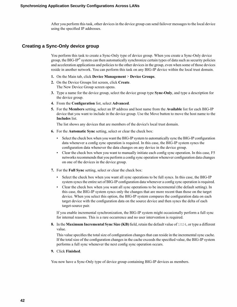
After you perform this task, other devices in the device group can send failover messages to the local deviceusing the specified IP addresses.
Creating a Sync-Only device group
You perform this task to create a Sync-Only type of device group. When you create a Sync-Only devicegroup, the BIG-IP® system can then automatically synchronize certain types of data such as security policiesand acceleration applications and policies to the other devices in the group, even when some of those devicesreside in another network. You can perform this task on any BIG-IP device within the local trust domain.
1. On the Main tab, click Device Management > Device Groups.2. On the Device Groups list screen, click Create.
The New Device Group screen opens.3. Type a name for the device group, select the device group type Sync-Only, and type a description for
the device group.4. From the Configuration list, select Advanced.5. For theMembers setting, select an IP address and host name from the Available list for each BIG-IP
device that you want to include in the device group. Use the Move button to move the host name to theIncludes list.The list shows any devices that are members of the device's local trust domain.
6. For the Automatic Sync setting, select or clear the check box:
• Select the check boxwhen youwant the BIG-IP system to automatically sync the BIG-IP configurationdata whenever a config sync operation is required. In this case, the BIG-IP system syncs theconfiguration data whenever the data changes on any device in the device group.
• Clear the check box when you want to manually initiate each config sync operation. In this case, F5networks recommends that you perform a config sync operation whenever configuration data changeson one of the devices in the device group.
7. For the Full Sync setting, select or clear the check box:
• Select the check box when you want all sync operations to be full syncs. In this case, the BIG-IPsystem syncs the entire set of BIG-IP configuration data whenever a config sync operation is required.
• Clear the check box when you want all sync operations to be incremental (the default setting). Inthis case, the BIG-IP system syncs only the changes that are more recent than those on the targetdevice. When you select this option, the BIG-IP system compares the configuration data on eachtarget device with the configuration data on the source device and then syncs the delta of eachtarget-source pair.
If you enable incremental synchronization, the BIG-IP system might occasionally perform a full syncfor internal reasons. This is a rare occurrence and no user intervention is required.
8. In theMaximum Incremental Sync Size (KB) field, retain the default value of 1024, or type a differentvalue.This value specifies the total size of configuration changes that can reside in the incremental sync cache.If the total size of the configuration changes in the cache exceeds the specified value, the BIG-IP systemperforms a full sync whenever the next config sync operation occurs.
9. Click Finished.
You now have a Sync-Only type of device group containing BIG-IP devices as members.
42
Synchronizing Application Security Configurations Across LANs
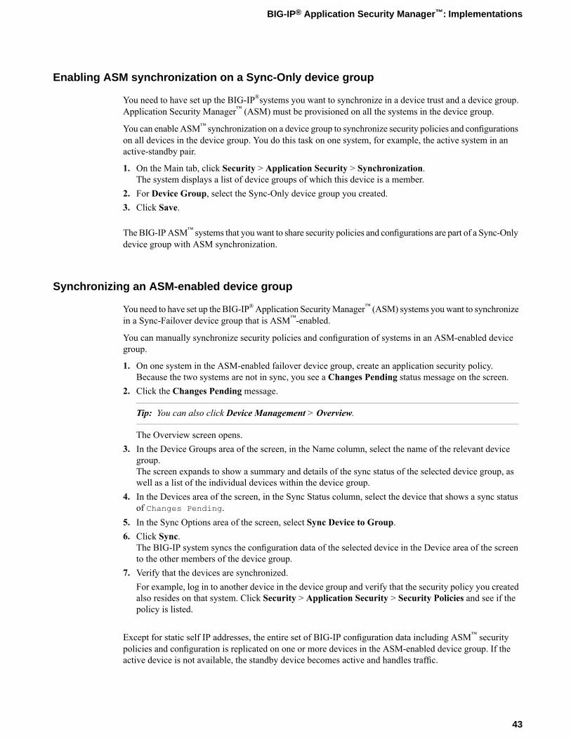
Enabling ASM synchronization on a Sync-Only device group
You need to have set up the BIG-IP®systems you want to synchronize in a device trust and a device group.Application Security Manager™ (ASM) must be provisioned on all the systems in the device group.
You can enable ASM™ synchronization on a device group to synchronize security policies and configurationson all devices in the device group. You do this task on one system, for example, the active system in anactive-standby pair.
1. On the Main tab, click Security > Application Security > Synchronization.The system displays a list of device groups of which this device is a member.
2. For Device Group, select the Sync-Only device group you created.3. Click Save.
The BIG-IPASM™ systems that youwant to share security policies and configurations are part of a Sync-Onlydevice group with ASM synchronization.
Synchronizing an ASM-enabled device group
You need to have set up the BIG-IP®Application SecurityManager™ (ASM) systems youwant to synchronizein a Sync-Failover device group that is ASM™-enabled.
You can manually synchronize security policies and configuration of systems in an ASM-enabled devicegroup.
1. On one system in the ASM-enabled failover device group, create an application security policy.Because the two systems are not in sync, you see a Changes Pending status message on the screen.
2. Click the Changes Pending message.
Tip: You can also click Device Management > Overview.
The Overview screen opens.3. In the Device Groups area of the screen, in the Name column, select the name of the relevant device
group.The screen expands to show a summary and details of the sync status of the selected device group, aswell as a list of the individual devices within the device group.
4. In the Devices area of the screen, in the Sync Status column, select the device that shows a sync statusof Changes Pending.
5. In the Sync Options area of the screen, select Sync Device to Group.6. Click Sync.
The BIG-IP system syncs the configuration data of the selected device in the Device area of the screento the other members of the device group.
7. Verify that the devices are synchronized.For example, log in to another device in the device group and verify that the security policy you createdalso resides on that system. Click Security > Application Security > Security Policies and see if thepolicy is listed.
Except for static self IP addresses, the entire set of BIG-IP configuration data including ASM™ securitypolicies and configuration is replicated on one or more devices in the ASM-enabled device group. If theactive device is not available, the standby device becomes active and handles traffic.
43
BIG-IP® Application Security Manager™: Implementations
You can create new security policies or update existing ones on any of the devices in the group, or updatethe ASM configuration options. You can manually synchronize changes you make on one device with theother devices in the ASM-enabled device group.
Implementation result
You have set up disaster recovery for multiple BIG-IP® systems running Application Security Manager™
(ASM). Each office or data center has an active system and a standby that takes over if the active systemshould fail. You must manually synchronize the BIG-IP configuration from one system to the other if youchange the configuration.
You can create new security policies or update existing ones on any of the devices in the group, or updatethe ASM™ configuration options (Application Security>Options). Any changes you make on one deviceare automatically synchronized with the other devices in the ASM-enabled Sync-Only device group.
If Attack Signatures Update Mode is scheduled for automatic update, the attack signature update settingsare synchronized. Each device in the device group updates itself independently according to the configuredschedule. If you manually upload attack signatures or click Upload Signatures to update from the server,the update is propagated to all of the devices in the device group.
44
Synchronizing Application Security Configurations Across LANs
Chapter
4Activating and Deactivating Security Policies
• Overview: Activating and deactivatingsecurity policies
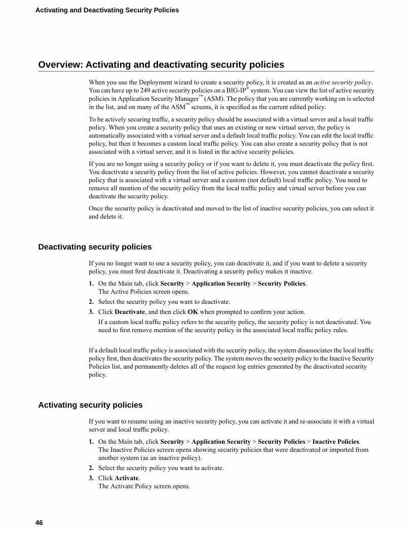
Overview: Activating and deactivating security policies
When you use the Deployment wizard to create a security policy, it is created as an active security policy.You can have up to 249 active security policies on a BIG-IP® system. You can view the list of active securitypolicies in Application Security Manager™ (ASM). The policy that you are currently working on is selectedin the list, and on many of the ASM™ screens, it is specified as the current edited policy.
To be actively securing traffic, a security policy should be associated with a virtual server and a local trafficpolicy. When you create a security policy that uses an existing or new virtual server, the policy isautomatically associated with a virtual server and a default local traffic policy. You can edit the local trafficpolicy, but then it becomes a custom local traffic policy. You can also create a security policy that is notassociated with a virtual server, and it is listed in the active security policies.
If you are no longer using a security policy or if you want to delete it, you must deactivate the policy first.You deactivate a security policy from the list of active policies. However, you cannot deactivate a securitypolicy that is associated with a virtual server and a custom (not default) local traffic policy. You need toremove all mention of the security policy from the local traffic policy and virtual server before you candeactivate the security policy.
Once the security policy is deactivated and moved to the list of inactive security policies, you can select itand delete it.
Deactivating security policies
If you no longer want to use a security policy, you can deactivate it, and if you want to delete a securitypolicy, you must first deactivate it. Deactivating a security policy makes it inactive.
1. On the Main tab, click Security > Application Security > Security Policies.The Active Policies screen opens.
2. Select the security policy you want to deactivate.3. Click Deactivate, and then click OK when prompted to confirm your action.
If a custom local traffic policy refers to the security policy, the security policy is not deactivated. Youneed to first remove mention of the security policy in the associated local traffic policy rules.
If a default local traffic policy is associated with the security policy, the system disassociates the local trafficpolicy first, then deactivates the security policy. The systemmoves the security policy to the Inactive SecurityPolicies list, and permanently deletes all of the request log entries generated by the deactivated securitypolicy.
Activating security policies
If you want to resume using an inactive security policy, you can activate it and re-associate it with a virtualserver and local traffic policy.
1. On the Main tab, click Security > Application Security > Security Policies > Inactive Policies.The Inactive Policies screen opens showing security policies that were deactivated or imported fromanother system (as an inactive policy).
2. Select the security policy you want to activate.3. Click Activate.
The Activate Policy screen opens.
46
Activating and Deactivating Security Policies
4. For Activation Type, specify whether to associate a virtual server with the security policy.
• To activate the security policy using the virtual server from another active security policy, clickReplace policy associated with virtual server. ForReplaced Policy, select the name of the securitypolicy you want to replace.
• To wait until later to associate a virtual server with the security policy, click Do not associate withvirtual server.
5. Click Activate.
The system moves the security policy to the Active Security Policies list. If you associated the securitypolicy with a virtual server, application security is enabled on the virtual server and the system creates adefault local traffic policy. The security policy you activated becomes the current active security policy,and the old security policy moves to the Inactive Security Policies list.
If you did not associate a virtual server with the security policy, the security policy is unusable because notraffic can go through it. As a result, it is meaningless to run the Policy Builder on this type of securitypolicy. You will need to manually associate it with a virtual server (in which case, the system automaticallycreates a default local traffic policy) in order for the security policy to handle traffic. You can also manuallyassociate a custom local traffic policy with a security policy.
Deleting security policies
Before you can delete a security policy, you must deactivate it first.
If you no longer want to use a security policy, you can delete it.
1. On the Main tab, click Security > Application Security > Security Policies > Inactive Policies.The Inactive Policies screen opens.
2. Select the security policy you want to delete.3. Click Delete, and then click OK when prompted to confirm your action.
The system permanently removes the security policy from the system.
47
BIG-IP® Application Security Manager™: Implementations


Chapter
5Importing and Exporting Security Policies
• Overview: Importing and exporting securitypolicies
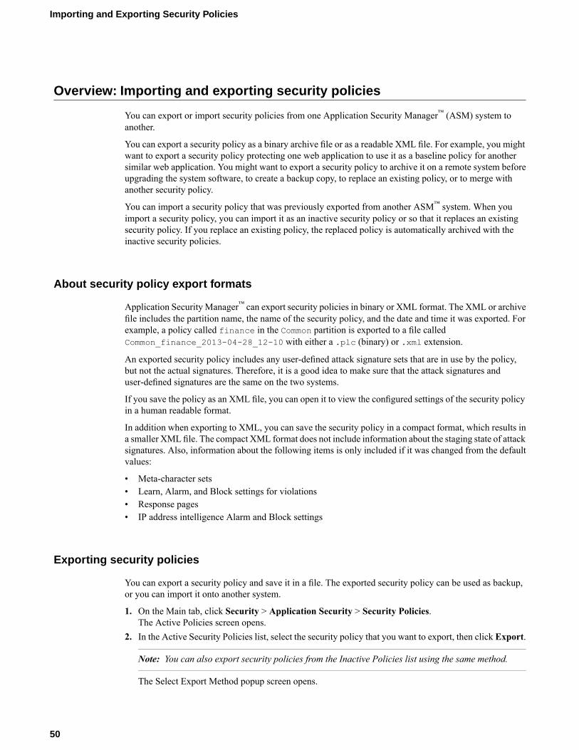
Overview: Importing and exporting security policies
You can export or import security policies from one Application Security Manager™ (ASM) system toanother.
You can export a security policy as a binary archive file or as a readable XML file. For example, you mightwant to export a security policy protecting one web application to use it as a baseline policy for anothersimilar web application. You might want to export a security policy to archive it on a remote system beforeupgrading the system software, to create a backup copy, to replace an existing policy, or to merge withanother security policy.
You can import a security policy that was previously exported from another ASM™ system. When youimport a security policy, you can import it as an inactive security policy or so that it replaces an existingsecurity policy. If you replace an existing policy, the replaced policy is automatically archived with theinactive security policies.
About security policy export formats
Application Security Manager™ can export security policies in binary or XML format. The XML or archivefile includes the partition name, the name of the security policy, and the date and time it was exported. Forexample, a policy called finance in the Common partition is exported to a file calledCommon_finance_2013-04-28_12-10 with either a .plc (binary) or .xml extension.
An exported security policy includes any user-defined attack signature sets that are in use by the policy,but not the actual signatures. Therefore, it is a good idea to make sure that the attack signatures anduser-defined signatures are the same on the two systems.
If you save the policy as an XML file, you can open it to view the configured settings of the security policyin a human readable format.
In addition when exporting to XML, you can save the security policy in a compact format, which results ina smaller XML file. The compact XML format does not include information about the staging state of attacksignatures. Also, information about the following items is only included if it was changed from the defaultvalues:
• Meta-character sets• Learn, Alarm, and Block settings for violations• Response pages• IP address intelligence Alarm and Block settings
Exporting security policies
You can export a security policy and save it in a file. The exported security policy can be used as backup,or you can import it onto another system.
1. On the Main tab, click Security > Application Security > Security Policies.The Active Policies screen opens.
2. In the Active Security Policies list, select the security policy that you want to export, then click Export.
Note: You can also export security policies from the Inactive Policies list using the same method.
The Select Export Method popup screen opens.
50
Importing and Exporting Security Policies
3. Select an export method.
• To save the security policy as an XML file, select Export security policy in XML format. Toreduce the size of the XML file, select the Compact format check box.
• To save the security policy as a policy archive file (.plc file), select Binary export of the securitypolicy.
• If the security policy integrates with a vulnerability assessment tool, select the Include VulnerabilityAssessment configuration and data check box.
4. Click Export.The system exports the security policy in the format you specified.
The exported security policy includes any user-defined signature sets that are in the policy, but not theuser-defined signatures themselves. Optionally, you can export user-defined signatures from the AttackSignature List (to see the list, go to Security > Options > Application Security > Attack Signatures >Attack Signatures List).
Importing security policies
Before you import a security policy from another system,make sure that the attack signatures and user-definedsignatures are the same on both systems. You also need access to the exported policy file.
You can import a security policy that was previously exported from another Application SecurityManager™system.
1. On the Main tab, click Security > Application Security > Security Policies.The Active Policies screen opens.
2. Click Import.The Import Security Policy screen opens.
3. Use the Choose File setting to navigate to the previously exported security policy.The exported security policy can be in XML (regular or compact) or binary (.plc) format.The system shows the name of the policy you plan to import and the policy encoding.
4. For the Import Target setting, select how to import the security policy.
• To place the uploaded policy into the list of inactive policies for later use, select Inactive SecurityPolicies List.
• To replace the currently active policy with the security policy you are importing, select ReplacedPolicy.
5. Click Import.The system imports the security policy and displays a success status message when the operation iscomplete.
If you replaced an existing policy, the imported security policy completely overwrites the existing securitypolicy. Also, the imported policy is then associated with the virtual server and local traffic policy that waspreviously associated with the policy you replaced.. The replaced policy is automatically archived with theinactive security policies.
If you imported a security policy to the list of inactive policies, it does not protect any application. Youhave to activate the inactive policy and associate it with a virtual server before it can protect an application.
51
BIG-IP® Application Security Manager™: Implementations

Chapter
6Comparing Security Policies
• Overview: Comparing security policies
Overview: Comparing security policies
Application Security Manager™ has a Policy Diff feature that lets you compare two security policies, viewthe differences between them, and copy the settings from one policy to the other. You can use the comparisonfor auditing purposes, to make two policies act similarly, or to simply view the differences between twosecurity policies. The Policy Diff feature is particularly useful for comparing a security policy in stagingand a production version. You can compare active security policies (with or without Policy Builder running),inactive security policies, and exported security policies. When you import security policies that wereexported from another system, they are placed in the inactive policies list.
You need to have a user role on the BIG-IP® system of Administrator or Web Application Security Editorto use Policy Diff to compare security policies.
Comparing security policies
Before you can compare security policies, the two policies must be on the same BIG-IP system, or accessiblefrom the system you are using (such as imported policies). They must also have the same language encoding,the same protocol independence (Differentiate between HTTP and HTTPS URLs) configuration, andthe same case sensitivity configuration. You can compare policies even if they are running Policy Builder,but because they are constantly changing, the comparison is done on copies of the policies to avoid corruptingthem.
Note: Only users with a role of Administrator, Application Security Administrator, or Application SecurityEditor can use Policy Diff to compare security policies.
You can compare two security policies to review the differences between them. While the two securitypolicies are being compared, the system prevents other users from saving changes to them.
1. On the Main tab, click Security > Application Security > Security Policies > Policy Diff.2. From the First Policy and Second Policy lists, select the security policies you want to compare or merge,
or click Browse to search your computer for an exported security policy.The two security policies you are comparing can be active, inactive, policies imported in binary or XMLformat, or a combination of both.
3. If you plan to merge security policy attributes, it is a good idea to safeguard the original security policy.In theWorking Mode field, select how you want to work.
DescriptionOption
Incorporate changes to one (or both) of the original security policiesdepending on the merge options you select without making a copy of it.
Work on Original
Make a copy of the security policy into which you are incorporating changes.Make a Copy
Work on a copy of the original security policy. First, a copy is made, thenincorporate possible changes on the original policies. If comparing one or
Work on Copy
more policies with Policy Builder enabled, this option is automaticallyselected (and the other options become unavailable).
4. Click the Calculate Differences button to compare the two security policies.
Note: The system does not compare navigation parameters. They are ignored and do not appear in theresults.
54
Comparing Security Policies

The Policy Differences Summary lists the number of differences for each entity type.5. Click any row in the Policy Differences Summary to view the differing entities with details about the
conflicting attributes.The system displays a list of the differing entities and shows details about each entity's conflictingattributes.
6. Review the differences between the two policies and determine whether or not you want to mergeattributes from one policy to the other.
55
BIG-IP® Application Security Manager™: Implementations

Chapter
7Merging Security Policies
• Overview: Merging security policies

Overview: Merging security policies
Application Security Manager™ has a policy merge option to combine two security policies. In the mergeprocess, the system compares, and then merges, specific features from one security policy to another.
The merge mechanism is lenient when merging security policies. The system resolves any conflicts thatoccur by using the more open settings in the target security policy. When the merge is complete, the systemshows the results of the merge process.
You can perform the merge in two ways:
• Automatically merge missing entities changing one policy or both policies.• Manually merge specific differing entities from one security policy to another.
Task summaryMerging security policies
Merging security policies
Only users with a role of Administrator, Application Security Administrator, or Application Security Editorcan use Policy Diff to merge security policies.
If you have two security policies with entities and attributes that you want to combine into one policy, youcan merge the two policies. For example, you can merge a security policy that you built offline into a securitypolicy that is on a production system. You can merge two security policies automatically, or by reviewingthe specific differences between them. You can perform the merge in two ways:
• Automatically merge missing entities changing one policy or both policies.• Manually merge specific differing entities from one security policy to another.
1. On the Main tab, click Security > Application Security.The Active Policies screen opens.
2. In the Security Policies area, click theMerge button.The Policy Diff screen opens.
3. From the First Policy and Second Policy lists, select the security policies you want to compare or merge,or click Browse to search your computer for an exported security policy.The two security policies you are comparing can be active, inactive, policies imported in binary or XMLformat, or a combination of both.
4. If you plan to merge security policy attributes, it is a good idea to safeguard the original security policy.In theWorking Mode field, select how you want to work.
DescriptionOption
Incorporate changes to one (or both) of the original security policiesdepending on the merge options you select without making a copy of it.
Work on Original
Make a copy of the security policy into which you are incorporating changes.Make a Copy
Work on a copy of the original security policy. First, a copy is made, thenincorporate possible changes on the original policies. If comparing one or
Work on Copy
more policies with Policy Builder enabled, this option is automaticallyselected (and the other options become unavailable).
5. Click the Calculate Differences button to compare the two security policies.
58
Merging Security Policies
Note: The system does not compare navigation parameters. They are ignored and do not appear in theresults.
The Policy Differences Summary lists the number of differences for each entity type.6. Decide whether you want to examine each difference in detail, or have the system resolve the differences.
• To merge the security policies automatically, skip to step 9.• To examine the differences before merging, proceed to step 7.
7. Click any row in the Policy Differences Summary to view the differing entities with details about theconflicting attributes.The system displays a list of the differing entities and shows details about each entity's conflictingattributes.
8. To merge the two security policies manually, address each difference.a) For each differing entity and attribute, move the ones you want into the merged security policy, or
click Ignore to leave them different.
Tip: Click the Details link to see very specific information about the entity in each security policy.
b) Click Save to save the changes you make.
When you click Save, the changed section is removed from the screen because it was resolved. Otherdiffering entities that still need to be resolved are still shown.
9. To automatically merge the differences between the two security policies, click Auto Merge.An Auto Merge popup screen opens.
10. In the Handle missing entities setting, specify how you want the system to treat entities that exist inone security policy but not the other.By default, both check boxes are selected; the auto-merge process adds unique entities from each policyinto the policy from which they are missing.
• To move missing entities from the second policy to the first, select Add all unique entities from<second policy> to <first policy>.
• To move missing entities from the first policy to the second, select Add all unique entities from<first policy> to <second policy>.
• If you do not want to merge missing entities, leave both check boxes blank.
11. In the Handle common entities for <first policy> and <second policy>, specify how you want thesystem to treat entities that have conflicting attributes.
• To make no changes to either policy when entities are different, select Leave unchanged.• To use the differing entities from the first policy and move them to the second, select Accept all
from <first policy> to <second policy>.• To use the differing entities from the second policy and move them to the first, select Accept all
from <second policy> to <first policy>.
12. ClickMerge.The system merges the two security policies.
13. On the right of First or Second Policy (for active policies only), click the Apply Policy button to putinto effect the changes made to the merged security policy.
The system logs all changes made either manually or automatically in the policy log, for auditing purposes.
59
BIG-IP® Application Security Manager™: Implementations

Chapter
8Setting Up IP Address Intelligence Blocking
• Overview: Setting up IP address intelligenceblocking
• IP address intelligence categories
Overview: Setting up IP address intelligence blocking
In Application SecurityManager™, you can use IP address intelligence blocking in a security policy to blockrequests from IP addresses that have questionable reputations. IP addresses from which attacks or spamhave originated are included in an IP intelligence database, along with the category describing the problem.The BIG-IP® systemmust connect to the IP intelligence database before you can use IP address intelligenceblocking.
You can configure a security policy to log (alarm) or block requests from IP addresses of questionablereputation, and to perform different actions depending on the categories of problems. For example, you canblock requests from IP addresses associated with Windows exploits and log requests from scanners.
You can create a whitelist of IP addresses that might be in the database, and allow them to access the webapplication regardless of their IP reputation. This is a way to ensure that traffic from known sources is notblocked because of IP address intelligence data.
You can also use iRules to instruct the system how to use IP address intelligence information.
Task summaryEnabling IP address intelligenceSetting up IP address intelligence blockingReviewing IP address intelligence statisticsCreating an iRule to log IP address intelligence informationCreating an iRule to reject requests with questionable IP addresses
Enabling IP address intelligence
The requirements for using IP address intelligence are:
• The system must have an IP Intelligence license.• The system must have an Internet connection either directly or through an HTTP proxy server.• The system must have DNS configured (go to System > Configuration > Device > DNS).
Important: IP address intelligence is enabled by default. You only need to enable it if it was previouslydisabled.
To enable IP address intelligence on the BIG-IP® system, you enable auto-update to connect the system tothe IP intelligence database.
1. Log in to the command line for the BIG-IP® system.2. To determine whether IP intelligence is enabled, type the following command: tmsh list sys db
iprep.autoupdateIf the value of the iprep.autoupdate variable is disable, IP intelligence is not enabled. If it isenable, your task is complete.
3. At the prompt, type tmsh modify sys db iprep.autoupdate value enableThe system downloads the IP intelligence database and stores it in the binary file,/var/IpRep/F5IpRep.dat. It is updated every 5 minutes.
4. If the BIG-IP system is behind a firewall, make sure that the BIG-IP system has external access tovector.brightcloud.com using port 443.That is the IP Intelligence server from which the system gets IP Intelligence information.
62
Setting Up IP Address Intelligence Blocking
5. (Optional) If the BIG-IP system connects to the Internet using a forward proxy server, set these systemdatabase variables.a) Type tmsh modify sys db proxy.host value hostname to specify the host name of the
proxy server.b) Type tmsh modify sys db proxy.port value port_number to specify the port number of
the proxy server.c) Type tmsh modify sys db proxy.username value username to specify the user name to
log in to the proxy server.d) Type tmsh modify sys db proxy.password value password to specify the password to
log in to the proxy server.
The IP address intelligence feature remains enabled unless you disable it with the command tmsh modifysys db iprep.autoupdate value disable.
You can create iRules® to instruct the system how to handle traffic from IP addresses with questionablereputations, or use Application Security Manager™ to configure IP address intelligence blocking.
Setting up IP address intelligence blocking
You can configure a security policy to log and block requests from source IP addresses that, according toan IP intelligence database, have a bad reputation and could cause a potential attack.
1. On the Main tab, click Security > Application Security > IP Addresses > IP Address Intelligence.The IP Address Intelligence screen opens.
2. In the Current edited policy list near the top of the screen, verify that the edited security policy is theone you want to work on.
3. Select the IP Address Intelligence check box.The screen refreshes, and displays additional configuration options.
4. For the IP AddressWhitelist setting, specify any IP addresses you want to allow, even if they are foundin the IP intelligence database.a) Type the IP Address and Subnet Mask of the address to consider safe.b) Click Add.
The system updates the whitelist with the new IP addresses.5. In the IP Address Intelligence Categories area, select Alarm or Block, or both, for the categories of IP
addresses you are interested in.
• Select Alarm to cause the system to log the IP address intelligence data (IP address intelligencecategory and status) on the Requests screen whenever a request is from a source IP address in thatcategory.
• Select Block to stop requests sent from a source IP address that matches that category
Tip: To select all categories at once, click the Alarm or Block column name check boxes.
6. Click Save.
The system matches source IP addresses to those in the IP address intelligence database. When a match isfound, the violation Access from malicious IP address occurs. The system determines whatcategory of reputation the IP address has, then logs or blocks the IP address according to how the IP AddressIntelligence categories are set.
63
BIG-IP® Application Security Manager™: Implementations
Reviewing IP address intelligence statistics
After you set up IP intelligence blocking on the Application Security Manager™, you can review statisticsconcerning how many requests were received from IP addresses with questionable reputations. You canalso view the requests from those IP addresses.
1. On the Main tab, click Security > Reporting > Application.The Charts screen opens.
2. In the Charts area, next to View by, click IP Address Intelligence.The chart shows details about IP addresses that were used to send the illegal requests, grouped accordingto their reputation in the IP intelligence database.
3. Hover over the pie chart or look at the Details table below it to see the categories of IP addresses withquestionable reputations.
4. Under Chart Path on the left, click View Requests to see the requests from IP addresses in the IPintelligence database.The Requests list opens.
5. Click any request to view details about the request.The screen expands to show more information about the request. IP address intelligence information isshown in the Source IP Address field in the request details. The details include the category of themalicious IP address and information about when the IP intelligence database was last updated.
6. If you have set up remote logging, you can also review IP intelligence data on the remote logger.
Based on the statistics and IP address intelligence categories that the IP addresses fall into, you can adjustwhat happens (alarm or block) when the system receives requests from IP addresses in different categories.
Creating an iRule to log IP address intelligence information
Before you can create an iRule to log IP address intelligence information, your systemmust have IP addressintelligence enabled.
You use iRules® to log IP address intelligence categories to the file /var/log/ltm. This is an example ofthe type of iRule you can write.
1. On the Main tab, click Local Traffic > iRules.The iRule List screen opens, displaying any existing iRules.
2. Click Create.The New iRule screen opens.
3. In the Name field, type a name between 1 and 31 characters, such as my_iRule.4. In the Definition field, type the iRule using Tool Command Language (Tcl) syntax.
For example, to log all IP addresses and any associated IP address intelligence categories, type thefollowing iRule:
when CLIENT_ACCEPTED {log local0. "IP Address Intelligence for IP address
[IP::client_addr]:[IP::reputation [IP::client_addr]]"
}
Tip: For complete and detailed information iRules syntax, see the F5 Networks DevCentral web site(http://devcentral.f5.com).
64
Setting Up IP Address Intelligence Blocking
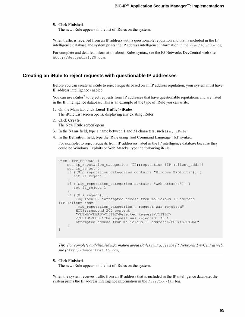
5. Click Finished.The new iRule appears in the list of iRules on the system.
When traffic is received from an IP address with a questionable reputation and that is included in the IPintelligence database, the system prints the IP address intelligence information in the /var/log/ltm log.
For complete and detailed information about iRules syntax, see the F5 Networks DevCentral web site,http://devcentral.f5.com.
Creating an iRule to reject requests with questionable IP addresses
Before you can create an iRule to reject requests based on an IP address reputation, your system must haveIP address intelligence enabled.
You can use iRules® to reject requests from IP addresses that have questionable reputations and are listedin the IP intelligence database. This is an example of the type of iRule you can write.
1. On the Main tab, click Local Traffic > iRules.The iRule List screen opens, displaying any existing iRules.
2. Click Create.The New iRule screen opens.
3. In the Name field, type a name between 1 and 31 characters, such as my_iRule.4. In the Definition field, type the iRule using Tool Command Language (Tcl) syntax.
For example, to reject requests from IP addresses listed in the IP intelligence database because theycould be Windows Exploits or Web Attacks, type the following iRule:
when HTTP_REQUEST {set ip_reputation_categories [IP::reputation [IP::client_addr]]set is_reject 0if {($ip_reputation_categories contains "Windows Exploits")} {
set is_reject 1}if {($ip_reputation_categories contains "Web Attacks")} {
set is_reject 1}if {($is_reject)} {
log local0. "Attempted access from malicious IP address[IP::client_addr]
($ip_reputation_categories), request was rejected"HTTP::respond 200 content"<HTML><HEAD><TITLE>Rejected Request</TITLE></HEAD><BODY>The request was rejected. <BR>Attempted access from malicious IP address</BODY></HTML>"
}}
Tip: For complete and detailed information about iRules syntax, see the F5 Networks DevCentral website (http://devcentral.f5.com).
5. Click Finished.The new iRule appears in the list of iRules on the system.
When the system receives traffic from an IP address that is included in the IP intelligence database, thesystem prints the IP address intelligence information in the /var/log/ltm log.
65
BIG-IP® Application Security Manager™: Implementations
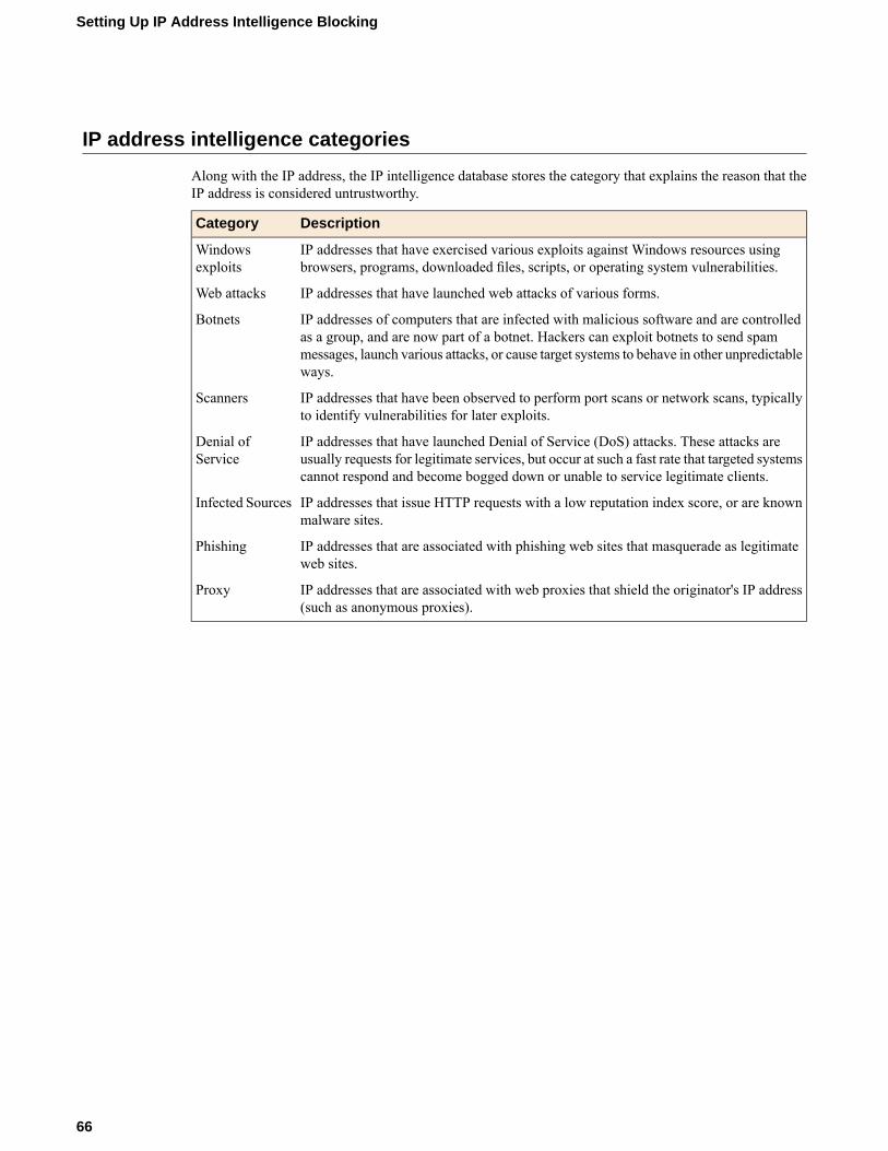
IP address intelligence categories
Along with the IP address, the IP intelligence database stores the category that explains the reason that theIP address is considered untrustworthy.
DescriptionCategory
IP addresses that have exercised various exploits against Windows resources usingbrowsers, programs, downloaded files, scripts, or operating system vulnerabilities.
Windowsexploits
IP addresses that have launched web attacks of various forms.Web attacks
IP addresses of computers that are infected with malicious software and are controlledas a group, and are now part of a botnet. Hackers can exploit botnets to send spam
Botnets
messages, launch various attacks, or cause target systems to behave in other unpredictableways.
IP addresses that have been observed to perform port scans or network scans, typicallyto identify vulnerabilities for later exploits.
Scanners
IP addresses that have launched Denial of Service (DoS) attacks. These attacks areusually requests for legitimate services, but occur at such a fast rate that targeted systemscannot respond and become bogged down or unable to service legitimate clients.
Denial ofService
IP addresses that issue HTTP requests with a low reputation index score, or are knownmalware sites.
Infected Sources
IP addresses that are associated with phishing web sites that masquerade as legitimateweb sites.
Phishing
IP addresses that are associated with web proxies that shield the originator's IP address(such as anonymous proxies).
Proxy
66
Setting Up IP Address Intelligence Blocking

Chapter
9Managing IP Address Exceptions
• Overview: Managing IP address exceptions
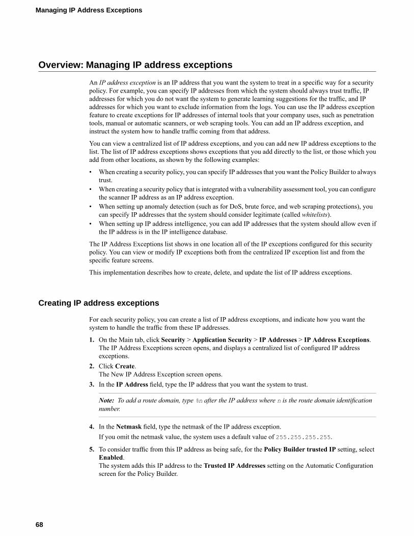
Overview: Managing IP address exceptions
An IP address exception is an IP address that you want the system to treat in a specific way for a securitypolicy. For example, you can specify IP addresses from which the system should always trust traffic, IPaddresses for which you do not want the system to generate learning suggestions for the traffic, and IPaddresses for which you want to exclude information from the logs. You can use the IP address exceptionfeature to create exceptions for IP addresses of internal tools that your company uses, such as penetrationtools, manual or automatic scanners, or web scraping tools. You can add an IP address exception, andinstruct the system how to handle traffic coming from that address.
You can view a centralized list of IP address exceptions, and you can add new IP address exceptions to thelist. The list of IP address exceptions shows exceptions that you add directly to the list, or those which youadd from other locations, as shown by the following examples:
• When creating a security policy, you can specify IP addresses that you want the Policy Builder to alwaystrust.
• When creating a security policy that is integrated with a vulnerability assessment tool, you can configurethe scanner IP address as an IP address exception.
• When setting up anomaly detection (such as for DoS, brute force, and web scraping protections), youcan specify IP addresses that the system should consider legitimate (called whitelists).
• When setting up IP address intelligence, you can add IP addresses that the system should allow even ifthe IP address is in the IP intelligence database.
The IP Address Exceptions list shows in one location all of the IP exceptions configured for this securitypolicy. You can view or modify IP exceptions both from the centralized IP exception list and from thespecific feature screens.
This implementation describes how to create, delete, and update the list of IP address exceptions.
Creating IP address exceptions
For each security policy, you can create a list of IP address exceptions, and indicate how you want thesystem to handle the traffic from these IP addresses.
1. On the Main tab, click Security > Application Security > IP Addresses > IP Address Exceptions.The IP Address Exceptions screen opens, and displays a centralized list of configured IP addressexceptions.
2. Click Create.The New IP Address Exception screen opens.
3. In the IP Address field, type the IP address that you want the system to trust.
Note: To add a route domain, type %n after the IP address where n is the route domain identificationnumber.
4. In the Netmask field, type the netmask of the IP address exception.If you omit the netmask value, the system uses a default value of 255.255.255.255.
5. To consider traffic from this IP address as being safe, for the Policy Builder trusted IP setting, selectEnabled.The system adds this IP address to the Trusted IP Addresses setting on the Automatic Configurationscreen for the Policy Builder.
68
Managing IP Address Exceptions
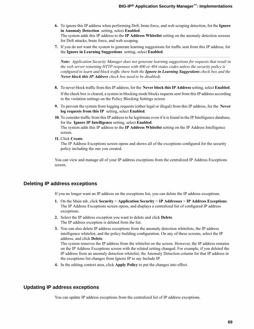
6. To ignore this IP address when performing DoS, brute force, and web scraping detection, for the Ignorein Anomaly Detection setting, select Enabled.The system adds this IP address to the IP Address Whitelist setting on the anomaly detection screensfor DoS attacks, brute force, and web scraping.
7. If you do not want the system to generate learning suggestions for traffic sent from this IP address, forthe Ignore in Learning Suggestions setting, select Enabled.
Note: Application Security Manager does not generate learning suggestions for requests that result inthe web server returning HTTP responses with 400 or 404 status codes unless the security policy isconfigured to learn and block traffic (here both the Ignore in Learning Suggestions check box and theNever block this IP Address check box need to be disabled).
8. To never block traffic from this IP address, for the Never block this IP Address setting, selectEnabled.If the check box is cleared, a system in blocking mode blocks requests sent from this IP address accordingto the violation settings on the Policy Blocking Settings screen.
9. To prevent the system from logging requests (either legal or illegal) from this IP address, for the Neverlog requests from this IP setting, select Enabled.
10. To consider traffic from this IP address to be legitimate even if it is found in the IP Intelligence database,for the Ignore IP Intelligence setting, select Enabled.The system adds this IP address to the IP Address Whitelist setting on the IP Address Intelligencescreen.
11. Click Create.The IP Address Exceptions screen opens and shows all of the exceptions configured for the securitypolicy including the one you created.
You can view and manage all of your IP address exceptions from the centralized IP Address Exceptionsscreen.
Deleting IP address exceptions
If you no longer want an IP address on the exceptions list, you can delete the IP address exceptions.
1. On the Main tab, click Security > Application Security > IP Addresses > IP Address Exceptions.The IP Address Exceptions screen opens, and displays a centralized list of configured IP addressexceptions.
2. Select the IP address exception you want to delete and click Delete.The IP address exception is deleted from the list.
3. You can also delete IP address exceptions from the anomaly detection whitelists, the IP addressintelligence whitelist, and the policy building configuration. On any of these screens, select the IPaddress, and click Delete.The system removes the IP address from the whitelist on the screen. However, the IP address remainson the IP Address Exceptions screen with the related setting changed. For example, if you deleted theIP address from an anomaly detection whitelist, the Anomaly Detection column for that IP address inthe exceptions list changes from Ignore IP to say Include IP.
4. In the editing context area, click Apply Policy to put the changes into effect.
Updating IP address exceptions
You can update IP address exceptions from the centralized list of IP address exceptions.
69
BIG-IP® Application Security Manager™: Implementations
1. On the Main tab, click Security > Application Security > IP Addresses > IP Address Exceptions.The IP Address Exceptions screen opens, and displays a centralized list of configured IP addressexceptions.
2. Click the IP address of the IP address exception you want to modify.The IP Address Exception Properties screen opens.
3. Change the settings as needed.4. Click Update.5. In the editing context area, click Apply Policy to put the changes into effect.
70
Managing IP Address Exceptions

Chapter
10Enforcing Application Use at Specific Geolocations
• Overview: Enforcing application use incertain geolocations
• Enforcing application use in certaingeolocations
• Setting up geolocation enforcement from arequest
Overview: Enforcing application use in certain geolocations
Geolocation software can identify the geographic location of a client or web application user. Geolocationrefers either to the process of assessing the location, or to the actual assessed location.
For applications protected by Application Security Manager™, you can use geolocation enforcement torestrict or allow application use in specific countries. You adjust the lists of which countries or locationsare allowed or disallowed in a security policy. If an application user tries to access the web application froma location that is not allowed, the Access from disallowed GeoLocation violation occurs. Bydefault, all locations are allowed, and the violation learn, alarm, and block flags are enabled.
Requests from certain locations, such as RFC-1918 addresses or unassigned global addresses, do not includea valid country code. The geolocation is shown as N/A in both the request, and the list of geolocations. Youhave the option to disallow N/A requests whose country of origination is unknown.
Enforcing application use in certain geolocations
Before you can set up geolocation enforcement, you need to create a security policy. If the BIG-IP®systemis deployed behind a proxy, you might need to set the Trust XFF Header option in the security policyproperties. Then the system identifies the location using the address from the XFF header instead of thesource IP address.
You can set up a security policy to allow or disallow access to the web application by users in specificcountries, areas, or from anonymous proxies.
1. On the Main tab, click Security > Application Security > Geolocation Enforcement.2. In the Current edited policy list near the top of the screen, verify that the edited security policy is the
one you want to work on.3. In the Geolocation List setting, use the move buttons to adjust the lists of allowed and disallowed
geolocations. To restrict traffic from anonymous proxies, move Anonymous Proxy to the disallowedgeolocations list.If no geolocations are assigned, the list displays the word None. The screen shows the value N/A in thelist of geolocations for cases where a user is in a location that cannot be identified, for example, if usingRFC-1918 addresses or unassigned global addresses.
Tip: You can approach geolocation enforcement by specifying either which locations you want todisallow or which locations you want to allow.
4. Click Save.The system saves the configuration settings.
5. In the editing context area, click Apply Policy to put the changes into effect.
Now, if a user in a disallowed location attempts to access the web application, the security policy (if inblockingmode) blocks the user and displays the violationAccess from disallowed Geolocation.
72
Enforcing Application Use at Specific Geolocations
Setting up geolocation enforcement from a request
You can restrict application use in certain geolocations by using the Requests list. This is an easy way torestrict users in a certain country from accessing the web application. By examining illegal request details,you can disallow the locations from which frequent problems are originating.
1. On the Main tab, expand Application Security and click Reporting.The Requests screen opens and shows all illegal requests that have occurred for this security policy.
2. In the Request List, click anywhere on a request.The screen displays details about the request including any violations associated with the request, andother details, such as the geolocation.
3. In the Request Details area, next to Geolocation, the country is displayed, and if the country is not onthe disallowed geolocation list, you see Disallow this Geolocation.The system asks you to verify that you want to disallow this geolocation. When you verify that you do,the system adds the country to the geolocation disallowed list.
4. Apply the change to the security policy: on the Main tab, click Policy, and then click Apply Policy.5. On the menu bar, click Geolocation Enforcement.
The Geolocation Enforcement screen opens, and you can see that the country was added to the disallowedgeolocations list.
Now, if a user in a disallowed location attempts to access the web application, the security policy (if inblockingmode) blocks the user and displays the violationAccess from disallowed Geolocation.
73
BIG-IP® Application Security Manager™: Implementations


Chapter
11Configuring Application Security Session Tracking
• Overview: Tracking application securitysessions using login pages
Overview:Tracking application security sessions using login pages
You can track sessions using login pages configured from within Application Security Manager™ (ASM™),or have the policy retrieve the user names from Access Policy Manager®(APM™). This implementationdescribes how to set up session tracking for a security policy using login pages. The advantage of usingsession tracking is that you are able to identify the user, session, or IP address that instigated an attack.
When creating login pages for the application, you define the URLs, parameters, and validation criteriarequired for users to log in to the application. User and session information is included in the system logsso you can track a particular session or user. The system can log activity, or block a user or session if eithergenerates too many violations.
If you configure session awareness, you can view the user and session information in the application securitycharts.
Task SummaryCreating login pagesEnforcing login pagesSetting up session trackingMonitoring user and session information
Creating login pages
In your security policy, you can create a login page to specify a login URL that presents a site that usersmust pass through to gain access to the web application. The login URL commonly leads to the login pageof the web application.
1. On the Main tab, click Security > Application Security > Sessions and Logins.The Login Pages List screen opens.
2. In the Current edited policy list near the top of the screen, verify that the edited security policy is theone you want to work on.
3. Click Create.The New Login Page screen opens.
4. For the Login URL setting, specify a URL that users must pass through to get to the application.a) From the list, select the type of URL: Explicit orWildcard.b) Select either HTTP or HTTPS based on the type of traffic the web application accepts.c) Type an explicit URL or wildcard expression in the box.
When you click in the field, the system lists URLs that it has seen, and you can select a URL fromthe list. Or, you can type explicit URLs in the format /login, and wildcard URLs without the slash,such as *.php.
5. From the Authentication Type list, select the method the web server uses to authenticate the loginURL's credentials with a web user.
DescriptionOption
The web application uses a form to collect and authenticate user credentials.If using this option, you also need to type the user name and passwordparameters written in the code of the HTML form.
HTML Form
The user name and password are transmitted in Base64 and stored on theserver in plain text.
HTTP BasicAuthentication
76
Configuring Application Security Session Tracking
DescriptionOption
The web server performs the authentication; user names and passwordsare not transmitted over the network, nor are they stored in plain text.
HTTP DigestAuthentication
Microsoft® LANManager authentication (also called Integrated WindowsAuthentication) does not transmit credentials in plain text, but requires acontinuous TCP connection between the server and client.
NTLM
6. In the Access Validation area, define at least one validation criteria for the login page response.If you define more than one validation criteria, the response must meet all the criteria before the systemallows the user to access the application.
Note: See the online help for definitions of the criteria.
7. Click Create to add the login page to the security policy.The new login page is added to the login pages list.
8. Add as many login pages as needed for your web application.9. In the editing context area, click Apply Policy to put the changes into effect.
The security policy now has one or more login pages associated with it.
You can now configure how the login pages are enforced, including the authentication URLs, logout URLs,and whether or not the login pages have time limits.
Enforcing login pages
Login enforcement settings prevent forceful browsing attacks where attackers gain access to restricted partsof the web application by supplying a URL directly. You can use login enforcement to force users to passthrough one URL (known as the login URL) before being allowed to display a different URL (known asthe target URL) where they can access restricted pages and resources. Login enforcement settings specifyhow the security policy enforces login pages including the expiration time, authenticated URLs, and logoutURLs. You can also use authenticated URLs to enforce idle time-outs on applications that are missing thisfunctionality.
1. On theMain tab, click Security >Application Security > Sessions and Logins >Login Enforcement.The Login Enforcement screen opens.
2. If you want the login URL to be valid for a limited time, set Expiration Time to Enabled, and type avalue, in seconds.
3. Specify the target URLs that users can access only by way of the login URLs:a) For the Authenticated URLs setting, type the target URL name in the format /private.php
(wildcards are allowed).b) Click Add to add the URL to the list of authenticated URLs.c) Add as many authenticated URLs as needed.
4. Optionally, specify the URLs used to log out of the web application:a) For the Logout URLs setting, type the URL in the format /logout.html (explicit URLs only).b) Click Add.c) Add as many logout URLs as needed.
5. Click Save.The system saves the configuration settings.
77
BIG-IP® Application Security Manager™: Implementations
If you specify authenticated URLs and a user tries to bypass them, the system now issues the Login URLbypassed violation. If a user session is idle and exceeds the expiration time, the system now issues theLogin URL expired violation, and the user can no longer reach the authenticated URLs. For both loginviolations, if the enforcement mode is blocking, the system now sends the Login Page Response to the client(see Application Security > Blocking > Response Pages).
Setting up session tracking
You can use session tracking to track, enforce, and report on user sessions and IP addresses. To performtracking, you enable session awareness and indicate how to associate the application user name with thesession. You can also determine whether to track violations and perform logging or blocking actions basedon the number of violations per user, session, and IP address.
1. On the Main tab, click Security > Application Security > Sessions and Logins > Session Tracking.The Session Tracking screen opens.
2. In the Session Tracking Configuration area, for Session Awareness, select the Enabled check box.3. Use the Application Username setting to specify the login pages for the application:
a) From the list, select Use Login Pages.b) Move the login pages for the application from the Available list to the Selected list.
If the login page is not listed, click Add to create it.
4. In the Violation Detection Actions area, select the Track Violations and Perform Actions, check box.5. In the Violation Detection Period field, type the number of seconds that indicates the sliding time
period to count violations for violation thresholds.The default is 900 seconds.
6. If you want the system to block all activity for a user, session, or IP address when the number of violationsexceeds the threshold, specify one or more of the following settings on the Block All tab.
Note: For the system to block requests, the security policy Enforcement Mode must be set to blocking(see Security > Application Security > Blocking > Settings) and some violations must be set to block.
DescriptionOptionSpecify which URLs to block after the number of violations exceeds theenabled thresholds. To block all URLs, select Block all URLs. To block
Blocked URLs
authenticated URLs protected by login pages, select Block AuthenticatedURLs.
SelectEnable and specify the number of violations allowed before the systemstarts to block this user's activity.
Username Threshold
SelectEnable and specify the number of violations allowed before the systemstarts to block activity for this HTTP session.
Session Threshold
SelectEnable and specify the number of violations allowed before the systemstarts to block the activity of this IP address.
IP Address Threshold
Specify how long to block users, sessions, or IP addresses if the number ofviolations exceeds the threshold. To block the user, session, or IP address
Block All Period
indefinitely, click Infinite. Otherwise, click User-defined and type thenumber of seconds to block the traffic. The default is 600 seconds.
78
Configuring Application Security Session Tracking
7. If you want the system to log activity when the number of user, session, or IP address violations exceedsthe threshold during the violation detection period, specify one or more of the following settings on theLog All Requests tab.
DescriptionOption
Select Enable and specify the number of violations allowed before thesystem starts logging this user's activity for the log all requests period.
Username Threshold
Select Enable and specify the number of violations allowed before thesystem starts logging activity for this HTTP session for the log all requestsperiod.
Session Threshold
Select Enable and specify the number of violations allowed before thesystem starts logging the activity of this IP address for the log all requestsperiod.
IP Address Threshold
Specify how long the system should log all requests when any of theenabled thresholds is reached. Type the number of seconds in the field.
Log All Requests Period
8. If you want more tolerant blocking for selected violations, such as those prone to false positives, specifyone or more of the following settings on the Delay Blocking tab.
Note: For the system to block requests, the security policy Enforcement Mode must be set to blocking(see Security > Application Security > Blocking > Settings) and the specified violations must be setto block.
DescriptionOptionSelectEnable and specify the number of violations a user must cause beforethe system begins blocking this user for the delay blocking period.
Username Threshold
SelectEnable and specify the number of violations users must cause (duringthe violation detection period) before the system begins blocking this HTTPsession for the delay blocking period.
Session Threshold
Select Enable and specify the number of violations allowed before thesystem begins blocking this IP address for the delay blocking period.
IP Address Threshold
Type the number of seconds that the system should block the user, session,or IP address when any of the enabled thresholds is reached.
Delay Blocking Period
Move the violations for which you want delay blocking from the Availablelist into the Selected list. If the selected violations occur, the system does
Associated Violations
not block traffic until one of the enabled thresholds is reached. At that point,the system blocks traffic causing those violations for the user, session, orIP address, but allows other transactions to pass.
9. Click Save.The system saves the configuration settings.
After you set up session tracking, if any enabled threshold exceeds the number of violations during thedetection period, the system starts the configured actions (block all, log all requests, and delay blocking).
Monitoring user and session information
To monitor user and session information, you first need to set up session tracking for the security policy.
79
BIG-IP® Application Security Manager™: Implementations
You can use the reporting tools in Application Security Manager™ to monitor user and session details,especially when you need to investigate suspicious activity that is occurring with certain users, sessions, orIP addresses.
1. On the Main tab, click Application Security Reporting.The Requests screen opens and shows all illegal requests that have occurred for this security policy.
2. In the Requests List, click anywhere on a request.The screen displays details about the request including any violations associated with the request andother details, such as the source IP address, user name, and session ID.
3. In the General Details area, next to the Username, Source IP Address, or Session ID, click the ShowSession Awareness details link.The screen displays the session awareness action flags that you can set.
4. Update the settings for your selections, as appropriate.DescriptionOption
When set to Enabled, the system immediately begins to log activity for theuser, session, or IP address and continues for the log activity period (600seconds by default).
Log All Requests
When set to Enabled, the system is immediately more tolerant of blockingselected violations (configured using Policy > Session Awareness. The delaylasts for the delay blocking period (600 seconds by default).
Delay Blocking
When set to Enabled, the system blocks all activity for this user, session, orIP address until further notice.
Block All
5. On the menu bar, click Session Tracking Status.You can see the list of action flags that you previously set. You can also add or release action flags fromthe Session Awareness screen.
6. To see a graphical view of the violations, from the Charts menu, choose Charts.The Charts screen opens where you can view pie charts and bar charts.
7. In the Charts area, next to View by, click the viewing criteria for the report you want to see.For example, you can view information about illegal requests by user name, session ID, or IP address.Then you can filter the Requests list by the top violator and examine request details for the user, session,or IP address.
8. Examine the charts and review the data you need. Click Export to create a PDF of any charts you wantto save.
After you set up session tracking, you can monitor the specific requests that cause violations by examiningeach request and reviewing graphical charts. From the Requests list, you can also set up logging, delayblocking, or block all requests for a specific user, session, or IP address.
80
Configuring Application Security Session Tracking
Chapter
12Tracking Application Security Sessions with APM
• Overview: Tracking application securitysessions using APM
• Prerequisites for setting up session trackingwith APM
Overview:Tracking application security sessions using APM
You can track sessions using login pages configured from within Application Security Manager™ (ASM™),or have the policy retrieve the user names from Access Policy Manager®(APM™). This implementationdescribes how to set up session tracking for a security policy using APM to verify user credentials. Then,you can set up session awareness fromwithin ASM to identify the user, session, or IP address that instigatedan attack.
If you configure session tracking, you can view the user and session information in the application securitycharts.
Prerequisites for setting up session tracking with APM
In order to set up session tracking from within Application Security Manager™ (ASM™) so that the securitypolicy retrieves the user names from Access Policy Manager ®(APM™), you need to perform basic thesesystem configuration tasks according to the needs of your networking configuration:
• Run the setup utility and create a management IP address.• License and provision ASM, APM, and Local Traffic Manager™ (LTM™).• Configure a DNS address (System > Configuration > Device > DNS).• Configure an NTP server (System > Configuration > Device > NTP).• Restart ASM (at the command line, type tmsh restart /sys service asm).
Task summary
Use the following tasks to set up application security session tracking with APM authentication integrated.Creating a VLANCreating a self IP address for a VLANCreating a local traffic pool for application securityCreating a virtual server to manage HTTPS trafficCreating a security policy automaticallyCreating an access profileConfiguring an access policyAdding the access profile to the virtual serverSetting up ASM session tracking with APMMonitoring user and session information
Creating a VLAN
VLANs represent a collection of hosts that can share network resources, regardless of their physical locationon the network. You create a VLAN to associate physical interfaces with that VLAN.
1. On the Main tab, click Network > VLANs.The VLAN List screen opens.
2. Click Create.The New VLAN screen opens.
82
Tracking Application Security Sessions with APM
3. In the Name field, type a unique name for the VLAN.4. For the Interfaces setting, click an interface number from the Available list, and use the Move button
to add the selected interface to the Untagged list. Repeat this step as necessary.5. Click Finished.
The screen refreshes, and displays the new VLAN in the list.
Creating a self IP address for a VLAN
Ensure that you have at least one VLAN configured before you create a self IP address.
Self IP addresses enable the BIG-IP® system, and other devices on the network, to route application trafficthrough the associated VLAN.
1. On the Main tab, click Network > Self IPs.The Self IPs screen opens.
2. Click Create.The New Self IP screen opens.
3. In the Name field, type a unique name for the self IP.4. In the IP Address field, type an IPv4 or IPv6 address.
This IP address should represent the address space of the VLAN that you specify with theVLAN/Tunnelsetting.
5. In the Netmask field, type the network mask for the specified IP address.6. From the VLAN/Tunnel list, select the VLAN to associate with this self IP address.
• On the internal network, select the VLAN that is associated with an internal interface or trunk.• On the external network, select the VLAN that is associated with an external interface or trunk.
7. Use the default values for all remaining settings.8. Click Finished.
The screen refreshes, and displays the new self IP address in the list.
The BIG-IP system can now send and receive TCP/IP traffic through the specified VLAN.
Creating a local traffic pool for application security
You can use a local traffic pool with Application Security Manager™ system to forward traffic to theappropriate resources.
Note: You can optionally create a pool as part of creating a security policy using the Deployment wizard.
1. On the Main tab, click Local Traffic > Pools.The Pool List screen opens.
2. Click Create.The New Pool screen opens.
3. In the Name field, type a unique name for the pool.4. In the Resources area, for the New Members setting, add to the pool the application servers that host
the web application:a) Type an IP address in the Address field.
83
BIG-IP® Application Security Manager™: Implementations

b) In the Service Port field, type a port number (for example, type 80 for the HTTP service), or selecta service name from the list.
c) Click Add.
5. Click Finished.
The BIG-IP® system configuration now includes a local traffic pool containing the resources that you wantto protect using Application Security Manager™.
Creating a virtual server to manage HTTPS traffic
You can create a virtual server to manage HTTPS traffic.
1. On the Main tab, click Local Traffic > Virtual Servers.The Virtual Server List screen opens.
2. Click the Create button.The New Virtual Server screen opens.
3. In the Name field, type a unique name for the virtual server.4. For the Destination setting, select Host and in the Address field, type the IP address for the virtual
server.5. In the Service Port field, type 443 or select HTTPS from the list.6. From the Configuration list, select Advanced.7. From the HTTP Profile list, select http.8. For the SSL Profile (Client) setting, from theAvailable list, select clientssl, and using theMove button,
move the name to the Selected list.9. (Optional) From the SSL Profile (Server) list, select serverssl.
Note: This setting ensures that there is an SSL connection between the HTTP virtual server and theexternal HTTPS server.
10. From the Source Address Translation list, select Auto Map.11. From the Default Pool list, select the pool that is configured for application security.12. Click Finished.
The HTTPS virtual server appears in the Virtual Server List screen.
Creating a security policy automatically
Before you can create a security policy, you must perform the minimal system configuration tasks includingdefining a VLAN, a self IP address, and other tasks required according to the needs of your networkingenvironment.
Application Security Manager™ can automatically create a security policy that is tailored to secure yourweb application.
1. On the Main tab, click Security > Application Security > Security Policies.The Active Policies screen opens.
2. Click the Create button.The Deployment wizard opens to the Select Local Traffic Deployment Scenario screen.
84
Tracking Application Security Sessions with APM
3. For the Local Traffic Deployment Scenario setting, specify a virtual server to use for the securitypolicy.
• To secure an existing virtual server that has no security policy associated with it, select ExistingVirtual Server and click Next.
• To create a new virtual server and pool with basic configuration settings, selectNew Virtual Serverand click Next.
• To create an active but unused security policy, select Do not associate with Virtual Server andclick Next. No traffic will go through this security policy until you associate it with a virtual server.The Policy Builder cannot begin automatically creating a policy until traffic is going to ASM throughthe virtual server.
The virtual server represents the web application you want to protect.The Configure Local Traffic Settings screen opens.
4. Configure the new or existing virtual server, and click Next.
• If creating a new virtual server, specify the protocol, name, IP address and port, pool IP address, andport.
• If using an existing virtual server, it must have an HTTP profile and cannot be associated with alocal traffic policy.
• If you selectDo not associate with Virtual Server, you will have to manually associate the securitypolicy with a virtual server at a later time. On the policy properties screen, you need to specify aname for the security policy.
The name of the new or existing virtual server becomes the name of the security policy.The Select Deployment Scenario screen opens.
5. For Deployment Scenario, select Create a policy automatically and click Next.The Configure Security Policy Properties screen opens.
6. From the Application Language list, select the language encoding of the application, or select Autodetect and let the system detect the language.
Important: You cannot change this setting after you have created the security policy.
7. If the application is not case-sensitive, clear the Security Policy is case sensitive check box. Otherwise,leave it selected.
Important: You cannot change this setting after you have created the security policy.
8. If you do not want the security policy to distinguish between HTTP and HTTPS URLs, clear theDifferentiate between HTTP and HTTPS URLs check box. Otherwise, leave it selected.
Important: You cannot change this setting after you have created the security policy.
9. Click Next.The Configure Attack Signatures screen opens.
10. To configure attack signatures, move the systems used by your web application from the AvailableSystems list into the Assigned Systems list.The system adds the attack signatures needed to protect the selected systems.
11. For the Signature Staging setting, verify that the default option Enabled is selected.
Note: Because the Real Traffic Policy Builder® begins building the security policy in Blocking mode,you can keep signature staging enabled to make sure that false positives do not occur.
New and updated attack signatures remain in staging for 7 days, and are not enforced (according to thelearn, alarm, and block flags) during that time.
85
BIG-IP® Application Security Manager™: Implementations
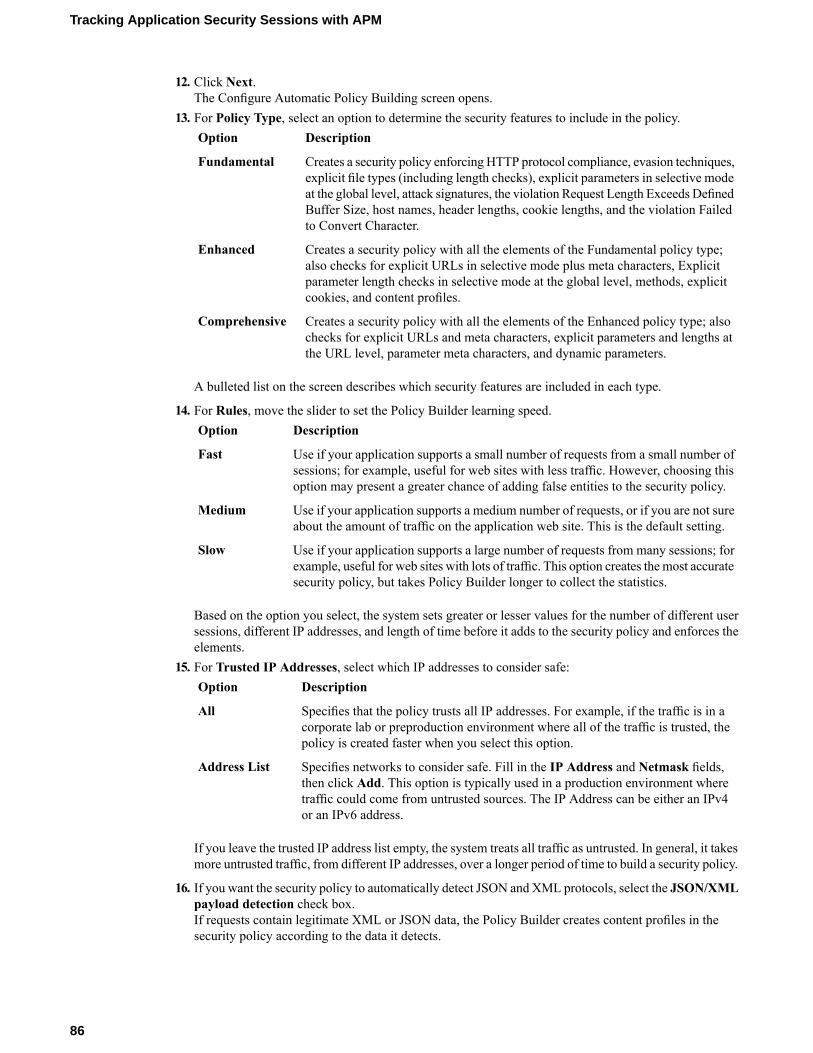
12. Click Next.The Configure Automatic Policy Building screen opens.
13. For Policy Type, select an option to determine the security features to include in the policy.DescriptionOption
Creates a security policy enforcing HTTP protocol compliance, evasion techniques,explicit file types (including length checks), explicit parameters in selective mode
Fundamental
at the global level, attack signatures, the violation Request Length Exceeds DefinedBuffer Size, host names, header lengths, cookie lengths, and the violation Failedto Convert Character.
Creates a security policy with all the elements of the Fundamental policy type;also checks for explicit URLs in selective mode plus meta characters, Explicit
Enhanced
parameter length checks in selective mode at the global level, methods, explicitcookies, and content profiles.
Creates a security policy with all the elements of the Enhanced policy type; alsochecks for explicit URLs and meta characters, explicit parameters and lengths atthe URL level, parameter meta characters, and dynamic parameters.
Comprehensive
A bulleted list on the screen describes which security features are included in each type.
14. For Rules, move the slider to set the Policy Builder learning speed.DescriptionOption
Use if your application supports a small number of requests from a small number ofsessions; for example, useful for web sites with less traffic. However, choosing thisoption may present a greater chance of adding false entities to the security policy.
Fast
Use if your application supports a medium number of requests, or if you are not sureabout the amount of traffic on the application web site. This is the default setting.
Medium
Use if your application supports a large number of requests from many sessions; forexample, useful for web sites with lots of traffic. This option creates the most accuratesecurity policy, but takes Policy Builder longer to collect the statistics.
Slow
Based on the option you select, the system sets greater or lesser values for the number of different usersessions, different IP addresses, and length of time before it adds to the security policy and enforces theelements.
15. For Trusted IP Addresses, select which IP addresses to consider safe:DescriptionOption
Specifies that the policy trusts all IP addresses. For example, if the traffic is in acorporate lab or preproduction environment where all of the traffic is trusted, thepolicy is created faster when you select this option.
All
Specifies networks to consider safe. Fill in the IP Address and Netmask fields,then click Add. This option is typically used in a production environment where
Address List
traffic could come from untrusted sources. The IP Address can be either an IPv4or an IPv6 address.
If you leave the trusted IP address list empty, the system treats all traffic as untrusted. In general, it takesmore untrusted traffic, from different IP addresses, over a longer period of time to build a security policy.
16. If you want the security policy to automatically detect JSON and XML protocols, select the JSON/XMLpayload detection check box.If requests contain legitimate XML or JSON data, the Policy Builder creates content profiles in thesecurity policy according to the data it detects.
86
Tracking Application Security Sessions with APM
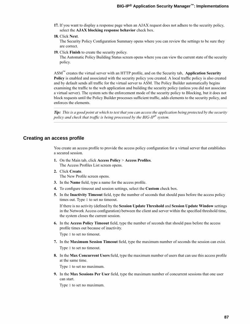
17. If you want to display a response page when an AJAX request does not adhere to the security policy,select the AJAX blocking response behavior check box.
18. Click Next.The Security Policy Configuration Summary opens where you can review the settings to be sure theyare correct.
19. Click Finish to create the security policy.The Automatic Policy Building Status screen opens where you can view the current state of the securitypolicy.
ASM™ creates the virtual server with an HTTP profile, and on the Security tab, Application SecurityPolicy is enabled and associated with the security policy you created. A local traffic policy is also createdand by default sends all traffic for the virtual server to ASM. The Policy Builder automatically beginsexamining the traffic to the web application and building the security policy (unless you did not associatea virtual server). The system sets the enforcement mode of the security policy to Blocking, but it does notblock requests until the Policy Builder processes sufficient traffic, adds elements to the security policy, andenforces the elements.
Tip: This is a good point at which to test that you can access the application being protected by the securitypolicy and check that traffic is being processed by the BIG-IP® system.
Creating an access profile
You create an access profile to provide the access policy configuration for a virtual server that establishesa secured session.
1. On the Main tab, click Access Policy > Access Profiles.The Access Profiles List screen opens.
2. Click Create.The New Profile screen opens.
3. In the Name field, type a name for the access profile.4. To configure timeout and session settings, select the Custom check box.5. In the Inactivity Timeout field, type the number of seconds that should pass before the access policy
times out. Type 0 to set no timeout.If there is no activity (defined by the Session Update Threshold and Session UpdateWindow settingsin the Network Access configuration) between the client and server within the specified threshold time,the system closes the current session.
6. In the Access Policy Timeout field, type the number of seconds that should pass before the accessprofile times out because of inactivity.Type 0 to set no timeout.
7. In theMaximum Session Timeout field, type the maximum number of seconds the session can exist.Type 0 to set no timeout.
8. In theMax Concurrent Users field, type the maximum number of users that can use this access profileat the same time.Type 0 to set no maximum.
9. In theMax Sessions Per User field, type the maximum number of concurrent sessions that one usercan start.Type 0 to set no maximum.
87
BIG-IP® Application Security Manager™: Implementations
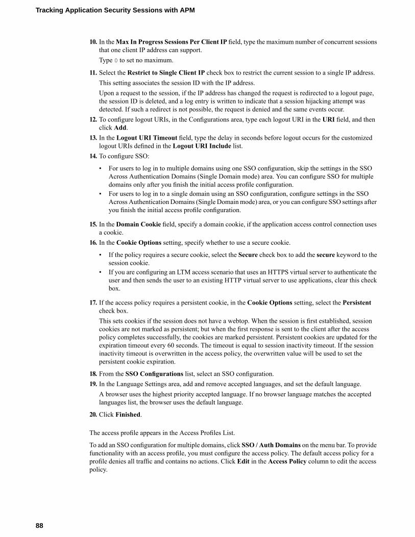
10. In theMax In Progress Sessions Per Client IP field, type the maximum number of concurrent sessionsthat one client IP address can support.Type 0 to set no maximum.
11. Select the Restrict to Single Client IP check box to restrict the current session to a single IP address.This setting associates the session ID with the IP address.Upon a request to the session, if the IP address has changed the request is redirected to a logout page,the session ID is deleted, and a log entry is written to indicate that a session hijacking attempt wasdetected. If such a redirect is not possible, the request is denied and the same events occur.
12. To configure logout URIs, in the Configurations area, type each logout URI in the URI field, and thenclick Add.
13. In the Logout URI Timeout field, type the delay in seconds before logout occurs for the customizedlogout URIs defined in the Logout URI Include list.
14. To configure SSO:
• For users to log in to multiple domains using one SSO configuration, skip the settings in the SSOAcross Authentication Domains (Single Domain mode) area. You can configure SSO for multipledomains only after you finish the initial access profile configuration.
• For users to log in to a single domain using an SSO configuration, configure settings in the SSOAcross AuthenticationDomains (Single Domainmode) area, or you can configure SSO settings afteryou finish the initial access profile configuration.
15. In the Domain Cookie field, specify a domain cookie, if the application access control connection usesa cookie.
16. In the Cookie Options setting, specify whether to use a secure cookie.
• If the policy requires a secure cookie, select the Secure check box to add the secure keyword to thesession cookie.
• If you are configuring an LTM access scenario that uses an HTTPS virtual server to authenticate theuser and then sends the user to an existing HTTP virtual server to use applications, clear this checkbox.
17. If the access policy requires a persistent cookie, in the Cookie Options setting, select the Persistentcheck box.This sets cookies if the session does not have a webtop. When the session is first established, sessioncookies are not marked as persistent; but when the first response is sent to the client after the accesspolicy completes successfully, the cookies are marked persistent. Persistent cookies are updated for theexpiration timeout every 60 seconds. The timeout is equal to session inactivity timeout. If the sessioninactivity timeout is overwritten in the access policy, the overwritten value will be used to set thepersistent cookie expiration.
18. From the SSO Configurations list, select an SSO configuration.19. In the Language Settings area, add and remove accepted languages, and set the default language.
A browser uses the highest priority accepted language. If no browser language matches the acceptedlanguages list, the browser uses the default language.
20. Click Finished.
The access profile appears in the Access Profiles List.
To add an SSO configuration for multiple domains, click SSO / Auth Domains on the menu bar. To providefunctionality with an access profile, you must configure the access policy. The default access policy for aprofile denies all traffic and contains no actions. Click Edit in the Access Policy column to edit the accesspolicy.
88
Tracking Application Security Sessions with APM
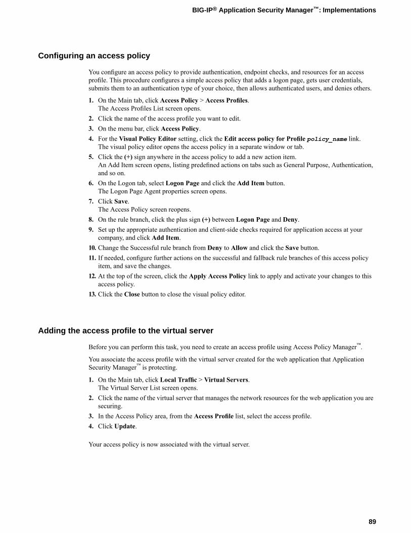
Configuring an access policy
You configure an access policy to provide authentication, endpoint checks, and resources for an accessprofile. This procedure configures a simple access policy that adds a logon page, gets user credentials,submits them to an authentication type of your choice, then allows authenticated users, and denies others.
1. On the Main tab, click Access Policy > Access Profiles.The Access Profiles List screen opens.
2. Click the name of the access profile you want to edit.3. On the menu bar, click Access Policy.4. For the Visual Policy Editor setting, click the Edit access policy for Profile policy_name link.
The visual policy editor opens the access policy in a separate window or tab.5. Click the (+) sign anywhere in the access policy to add a new action item.
An Add Item screen opens, listing predefined actions on tabs such as General Purpose, Authentication,and so on.
6. On the Logon tab, select Logon Page and click the Add Item button.The Logon Page Agent properties screen opens.
7. Click Save.The Access Policy screen reopens.
8. On the rule branch, click the plus sign (+) between Logon Page and Deny.9. Set up the appropriate authentication and client-side checks required for application access at your
company, and click Add Item.10. Change the Successful rule branch from Deny to Allow and click the Save button.11. If needed, configure further actions on the successful and fallback rule branches of this access policy
item, and save the changes.12. At the top of the screen, click the Apply Access Policy link to apply and activate your changes to this
access policy.13. Click the Close button to close the visual policy editor.
Adding the access profile to the virtual server
Before you can perform this task, you need to create an access profile using Access Policy Manager™.
You associate the access profile with the virtual server created for the web application that ApplicationSecurity Manager™ is protecting.
1. On the Main tab, click Local Traffic > Virtual Servers.The Virtual Server List screen opens.
2. Click the name of the virtual server that manages the network resources for the web application you aresecuring.
3. In the Access Policy area, from the Access Profile list, select the access profile.4. Click Update.
Your access policy is now associated with the virtual server.
89
BIG-IP® Application Security Manager™: Implementations
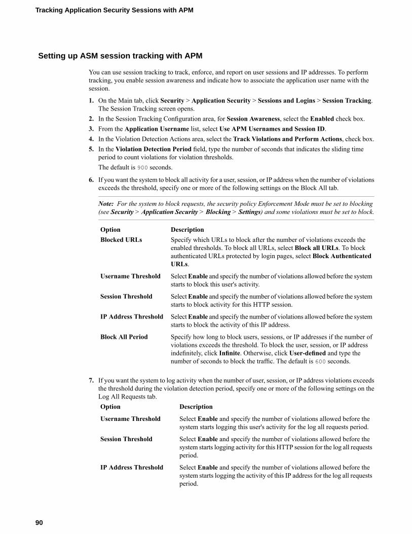
Setting up ASM session tracking with APM
You can use session tracking to track, enforce, and report on user sessions and IP addresses. To performtracking, you enable session awareness and indicate how to associate the application user name with thesession.
1. On the Main tab, click Security > Application Security > Sessions and Logins > Session Tracking.The Session Tracking screen opens.
2. In the Session Tracking Configuration area, for Session Awareness, select the Enabled check box.3. From the Application Username list, select Use APM Usernames and Session ID.4. In the Violation Detection Actions area, select the Track Violations and Perform Actions, check box.5. In the Violation Detection Period field, type the number of seconds that indicates the sliding time
period to count violations for violation thresholds.The default is 900 seconds.
6. If you want the system to block all activity for a user, session, or IP address when the number of violationsexceeds the threshold, specify one or more of the following settings on the Block All tab.
Note: For the system to block requests, the security policy Enforcement Mode must be set to blocking(see Security > Application Security > Blocking > Settings) and some violations must be set to block.
DescriptionOptionSpecify which URLs to block after the number of violations exceeds theenabled thresholds. To block all URLs, select Block all URLs. To block
Blocked URLs
authenticated URLs protected by login pages, select Block AuthenticatedURLs.
SelectEnable and specify the number of violations allowed before the systemstarts to block this user's activity.
Username Threshold
SelectEnable and specify the number of violations allowed before the systemstarts to block activity for this HTTP session.
Session Threshold
SelectEnable and specify the number of violations allowed before the systemstarts to block the activity of this IP address.
IP Address Threshold
Specify how long to block users, sessions, or IP addresses if the number ofviolations exceeds the threshold. To block the user, session, or IP address
Block All Period
indefinitely, click Infinite. Otherwise, click User-defined and type thenumber of seconds to block the traffic. The default is 600 seconds.
7. If you want the system to log activity when the number of user, session, or IP address violations exceedsthe threshold during the violation detection period, specify one or more of the following settings on theLog All Requests tab.
DescriptionOption
Select Enable and specify the number of violations allowed before thesystem starts logging this user's activity for the log all requests period.
Username Threshold
Select Enable and specify the number of violations allowed before thesystem starts logging activity for this HTTP session for the log all requestsperiod.
Session Threshold
Select Enable and specify the number of violations allowed before thesystem starts logging the activity of this IP address for the log all requestsperiod.
IP Address Threshold
90
Tracking Application Security Sessions with APM
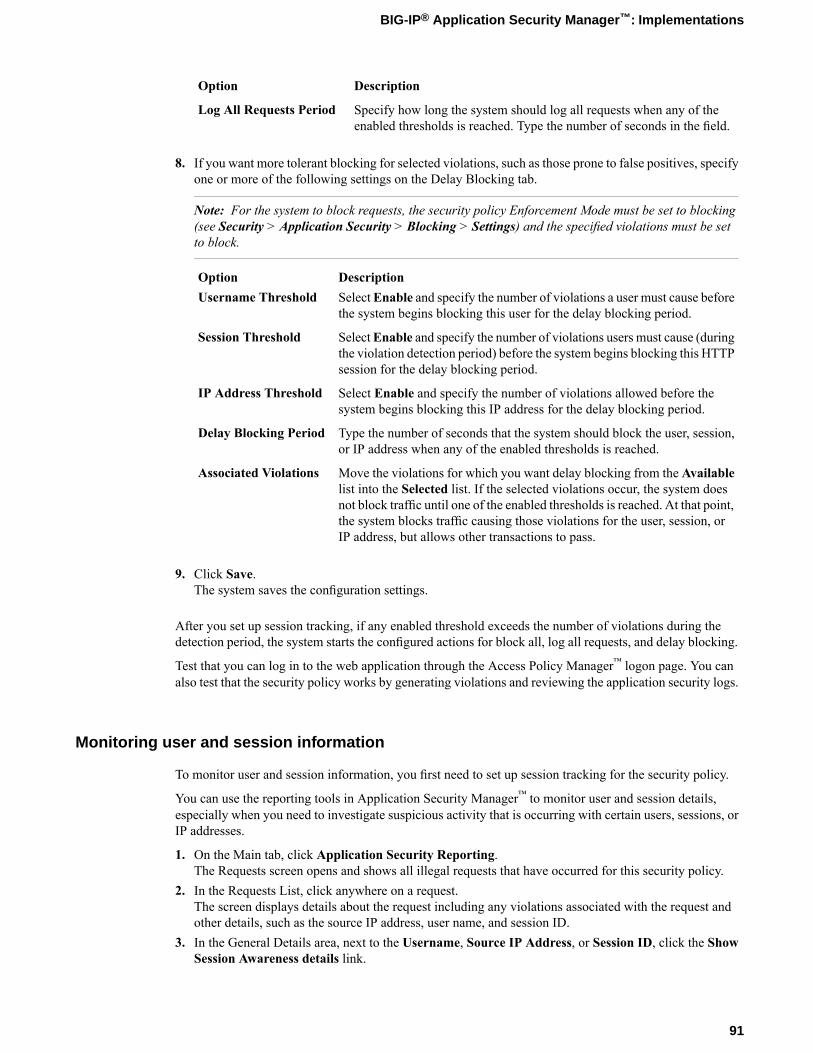
DescriptionOption
Specify how long the system should log all requests when any of theenabled thresholds is reached. Type the number of seconds in the field.
Log All Requests Period
8. If you want more tolerant blocking for selected violations, such as those prone to false positives, specifyone or more of the following settings on the Delay Blocking tab.
Note: For the system to block requests, the security policy Enforcement Mode must be set to blocking(see Security > Application Security > Blocking > Settings) and the specified violations must be setto block.
DescriptionOptionSelectEnable and specify the number of violations a user must cause beforethe system begins blocking this user for the delay blocking period.
Username Threshold
SelectEnable and specify the number of violations users must cause (duringthe violation detection period) before the system begins blocking this HTTPsession for the delay blocking period.
Session Threshold
Select Enable and specify the number of violations allowed before thesystem begins blocking this IP address for the delay blocking period.
IP Address Threshold
Type the number of seconds that the system should block the user, session,or IP address when any of the enabled thresholds is reached.
Delay Blocking Period
Move the violations for which you want delay blocking from the Availablelist into the Selected list. If the selected violations occur, the system does
Associated Violations
not block traffic until one of the enabled thresholds is reached. At that point,the system blocks traffic causing those violations for the user, session, orIP address, but allows other transactions to pass.
9. Click Save.The system saves the configuration settings.
After you set up session tracking, if any enabled threshold exceeds the number of violations during thedetection period, the system starts the configured actions for block all, log all requests, and delay blocking.
Test that you can log in to the web application through the Access Policy Manager™ logon page. You canalso test that the security policy works by generating violations and reviewing the application security logs.
Monitoring user and session information
To monitor user and session information, you first need to set up session tracking for the security policy.
You can use the reporting tools in Application Security Manager™ to monitor user and session details,especially when you need to investigate suspicious activity that is occurring with certain users, sessions, orIP addresses.
1. On the Main tab, click Application Security Reporting.The Requests screen opens and shows all illegal requests that have occurred for this security policy.
2. In the Requests List, click anywhere on a request.The screen displays details about the request including any violations associated with the request andother details, such as the source IP address, user name, and session ID.
3. In the General Details area, next to the Username, Source IP Address, or Session ID, click the ShowSession Awareness details link.
91
BIG-IP® Application Security Manager™: Implementations

The screen displays the session awareness action flags that you can set.4. Update the settings for your selections, as appropriate.
DescriptionOption
When set to Enabled, the system immediately begins to log activity for theuser, session, or IP address and continues for the log activity period (600seconds by default).
Log All Requests
When set to Enabled, the system is immediately more tolerant of blockingselected violations (configured using Policy > Session Awareness. The delaylasts for the delay blocking period (600 seconds by default).
Delay Blocking
When set to Enabled, the system blocks all activity for this user, session, orIP address until further notice.
Block All
5. On the menu bar, click Session Tracking Status.You can see the list of action flags that you previously set. You can also add or release action flags fromthe Session Awareness screen.
6. To see a graphical view of the violations, from the Charts menu, choose Charts.The Charts screen opens where you can view pie charts and bar charts.
7. In the Charts area, next to View by, click the viewing criteria for the report you want to see.For example, you can view information about illegal requests by user name, session ID, or IP address.Then you can filter the Requests list by the top violator and examine request details for the user, session,or IP address.
8. Examine the charts and review the data you need. Click Export to create a PDF of any charts you wantto save.
After you set up session tracking, you can monitor the specific requests that cause violations by examiningeach request and reviewing graphical charts. From the Requests list, you can also set up logging, delayblocking, or block all requests for a specific user, session, or IP address.
92
Tracking Application Security Sessions with APM

Chapter
13Automatically Creating Security Policies for AJAXApplications
• Application security for applications that useAJAX
• Overview: Creating a security policy forapplications that use AJAX
• Implementation result
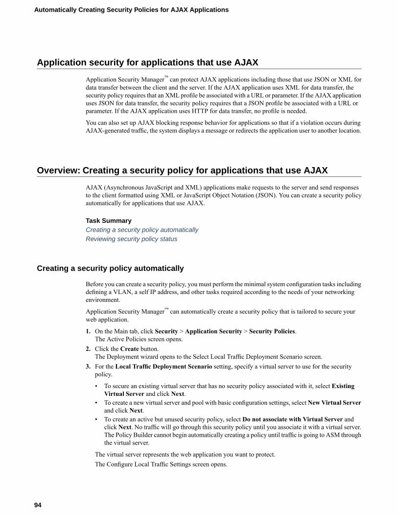
Application security for applications that use AJAX
Application Security Manager™ can protect AJAX applications including those that use JSON or XML fordata transfer between the client and the server. If the AJAX application uses XML for data transfer, thesecurity policy requires that an XML profile be associated with a URL or parameter. If the AJAX applicationuses JSON for data transfer, the security policy requires that a JSON profile be associated with a URL orparameter. If the AJAX application uses HTTP for data transfer, no profile is needed.
You can also set up AJAX blocking response behavior for applications so that if a violation occurs duringAJAX-generated traffic, the system displays a message or redirects the application user to another location.
Overview: Creating a security policy for applications that use AJAX
AJAX (Asynchronous JavaScript and XML) applications make requests to the server and send responsesto the client formatted using XML or JavaScript Object Notation (JSON). You can create a security policyautomatically for applications that use AJAX.
Task SummaryCreating a security policy automaticallyReviewing security policy status
Creating a security policy automatically
Before you can create a security policy, you must perform the minimal system configuration tasks includingdefining a VLAN, a self IP address, and other tasks required according to the needs of your networkingenvironment.
Application Security Manager™ can automatically create a security policy that is tailored to secure yourweb application.
1. On the Main tab, click Security > Application Security > Security Policies.The Active Policies screen opens.
2. Click the Create button.The Deployment wizard opens to the Select Local Traffic Deployment Scenario screen.
3. For the Local Traffic Deployment Scenario setting, specify a virtual server to use for the securitypolicy.
• To secure an existing virtual server that has no security policy associated with it, select ExistingVirtual Server and click Next.
• To create a new virtual server and pool with basic configuration settings, selectNew Virtual Serverand click Next.
• To create an active but unused security policy, select Do not associate with Virtual Server andclick Next. No traffic will go through this security policy until you associate it with a virtual server.The Policy Builder cannot begin automatically creating a policy until traffic is going to ASM throughthe virtual server.
The virtual server represents the web application you want to protect.The Configure Local Traffic Settings screen opens.
94
Automatically Creating Security Policies for AJAX Applications
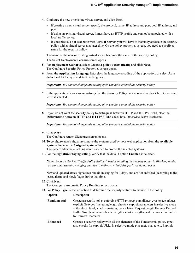
4. Configure the new or existing virtual server, and click Next.
• If creating a new virtual server, specify the protocol, name, IP address and port, pool IP address, andport.
• If using an existing virtual server, it must have an HTTP profile and cannot be associated with alocal traffic policy.
• If you selectDo not associate with Virtual Server, you will have to manually associate the securitypolicy with a virtual server at a later time. On the policy properties screen, you need to specify aname for the security policy.
The name of the new or existing virtual server becomes the name of the security policy.The Select Deployment Scenario screen opens.
5. For Deployment Scenario, select Create a policy automatically and click Next.The Configure Security Policy Properties screen opens.
6. From the Application Language list, select the language encoding of the application, or select Autodetect and let the system detect the language.
Important: You cannot change this setting after you have created the security policy.
7. If the application is not case-sensitive, clear the Security Policy is case sensitive check box. Otherwise,leave it selected.
Important: You cannot change this setting after you have created the security policy.
8. If you do not want the security policy to distinguish between HTTP and HTTPS URLs, clear theDifferentiate between HTTP and HTTPS URLs check box. Otherwise, leave it selected.
Important: You cannot change this setting after you have created the security policy.
9. Click Next.The Configure Attack Signatures screen opens.
10. To configure attack signatures, move the systems used by your web application from the AvailableSystems list into the Assigned Systems list.The system adds the attack signatures needed to protect the selected systems.
11. For the Signature Staging setting, verify that the default option Enabled is selected.
Note: Because the Real Traffic Policy Builder® begins building the security policy in Blocking mode,you can keep signature staging enabled to make sure that false positives do not occur.
New and updated attack signatures remain in staging for 7 days, and are not enforced (according to thelearn, alarm, and block flags) during that time.
12. Click Next.The Configure Automatic Policy Building screen opens.
13. For Policy Type, select an option to determine the security features to include in the policy.DescriptionOption
Creates a security policy enforcing HTTP protocol compliance, evasion techniques,explicit file types (including length checks), explicit parameters in selective mode
Fundamental
at the global level, attack signatures, the violation Request Length Exceeds DefinedBuffer Size, host names, header lengths, cookie lengths, and the violation Failedto Convert Character.
Creates a security policy with all the elements of the Fundamental policy type;also checks for explicit URLs in selective mode plus meta characters, Explicit
Enhanced
95
BIG-IP® Application Security Manager™: Implementations
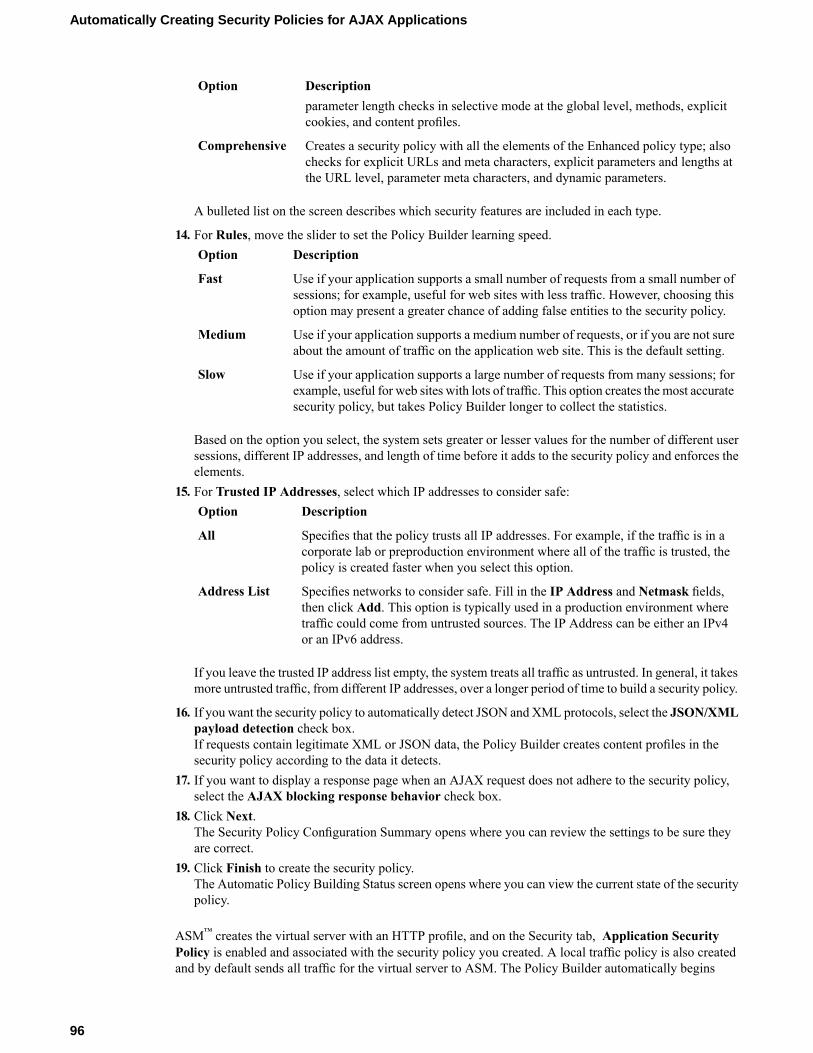
DescriptionOptionparameter length checks in selective mode at the global level, methods, explicitcookies, and content profiles.
Creates a security policy with all the elements of the Enhanced policy type; alsochecks for explicit URLs and meta characters, explicit parameters and lengths atthe URL level, parameter meta characters, and dynamic parameters.
Comprehensive
A bulleted list on the screen describes which security features are included in each type.
14. For Rules, move the slider to set the Policy Builder learning speed.DescriptionOption
Use if your application supports a small number of requests from a small number ofsessions; for example, useful for web sites with less traffic. However, choosing thisoption may present a greater chance of adding false entities to the security policy.
Fast
Use if your application supports a medium number of requests, or if you are not sureabout the amount of traffic on the application web site. This is the default setting.
Medium
Use if your application supports a large number of requests from many sessions; forexample, useful for web sites with lots of traffic. This option creates the most accuratesecurity policy, but takes Policy Builder longer to collect the statistics.
Slow
Based on the option you select, the system sets greater or lesser values for the number of different usersessions, different IP addresses, and length of time before it adds to the security policy and enforces theelements.
15. For Trusted IP Addresses, select which IP addresses to consider safe:DescriptionOption
Specifies that the policy trusts all IP addresses. For example, if the traffic is in acorporate lab or preproduction environment where all of the traffic is trusted, thepolicy is created faster when you select this option.
All
Specifies networks to consider safe. Fill in the IP Address and Netmask fields,then click Add. This option is typically used in a production environment where
Address List
traffic could come from untrusted sources. The IP Address can be either an IPv4or an IPv6 address.
If you leave the trusted IP address list empty, the system treats all traffic as untrusted. In general, it takesmore untrusted traffic, from different IP addresses, over a longer period of time to build a security policy.
16. If you want the security policy to automatically detect JSON and XML protocols, select the JSON/XMLpayload detection check box.If requests contain legitimate XML or JSON data, the Policy Builder creates content profiles in thesecurity policy according to the data it detects.
17. If you want to display a response page when an AJAX request does not adhere to the security policy,select the AJAX blocking response behavior check box.
18. Click Next.The Security Policy Configuration Summary opens where you can review the settings to be sure theyare correct.
19. Click Finish to create the security policy.The Automatic Policy Building Status screen opens where you can view the current state of the securitypolicy.
ASM™ creates the virtual server with an HTTP profile, and on the Security tab, Application SecurityPolicy is enabled and associated with the security policy you created. A local traffic policy is also createdand by default sends all traffic for the virtual server to ASM. The Policy Builder automatically begins
96
Automatically Creating Security Policies for AJAX Applications
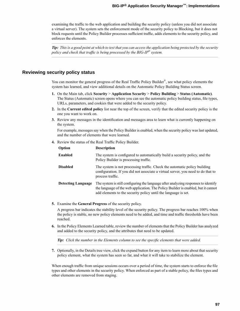
examining the traffic to the web application and building the security policy (unless you did not associatea virtual server). The system sets the enforcement mode of the security policy to Blocking, but it does notblock requests until the Policy Builder processes sufficient traffic, adds elements to the security policy, andenforces the elements.
Tip: This is a good point at which to test that you can access the application being protected by the securitypolicy and check that traffic is being processed by the BIG-IP® system.
Reviewing security policy status
You can monitor the general progress of the Real Traffic Policy Builder®, see what policy elements thesystem has learned, and view additional details on the Automatic Policy Building Status screen.
1. On the Main tab, click Security > Application Security > Policy Building > Status (Automatic).The Status (Automatic) screen opens where you can see the automatic policy building status, file types,URLs, parameters, and cookies that were added to the security policy.
2. In the Current edited policy list near the top of the screen, verify that the edited security policy is theone you want to work on.
3. Review any messages in the identification and messages area to learn what is currently happening onthe system.For example, messages say when the Policy Builder is enabled, when the security policy was last updated,and the number of elements that were learned.
4. Review the status of the Real Traffic Policy Builder.DescriptionOption
The system is configured to automatically build a security policy, and thePolicy Builder is processing traffic.
Enabled
The system is not processing traffic. Check the automatic policy buildingconfiguration. If you did not associate a virtual server, you need to do that toprocess traffic.
Disabled
The system is still configuring the language after analyzing responses to identifythe language of the web application. The Policy Builder is enabled, but it cannotadd elements to the security policy until the language is set.
Detecting Language
5. Examine the General Progress of the security policy.A progress bar indicates the stability level of the security policy. The progress bar reaches 100% whenthe policy is stable, no new policy elements need to be added, and time and traffic thresholds have beenreached.
6. In the Policy Elements Learned table, review the number of elements that the Policy Builder has analyzedand added to the security policy, and the attributes that need to be updated.
Tip: Click the number in the Elements column to see the specific elements that were added.
7. Optionally, in the Details tree view, click the expand button for any item to learn more about that securitypolicy element, what the system has seen so far, and what it will take to stabilize the element.
When enough traffic from unique sessions occurs over a period of time, the system starts to enforce the filetypes and other elements in the security policy. When enforced as part of a stable policy, the files types andother elements are removed from staging.
97
BIG-IP® Application Security Manager™: Implementations
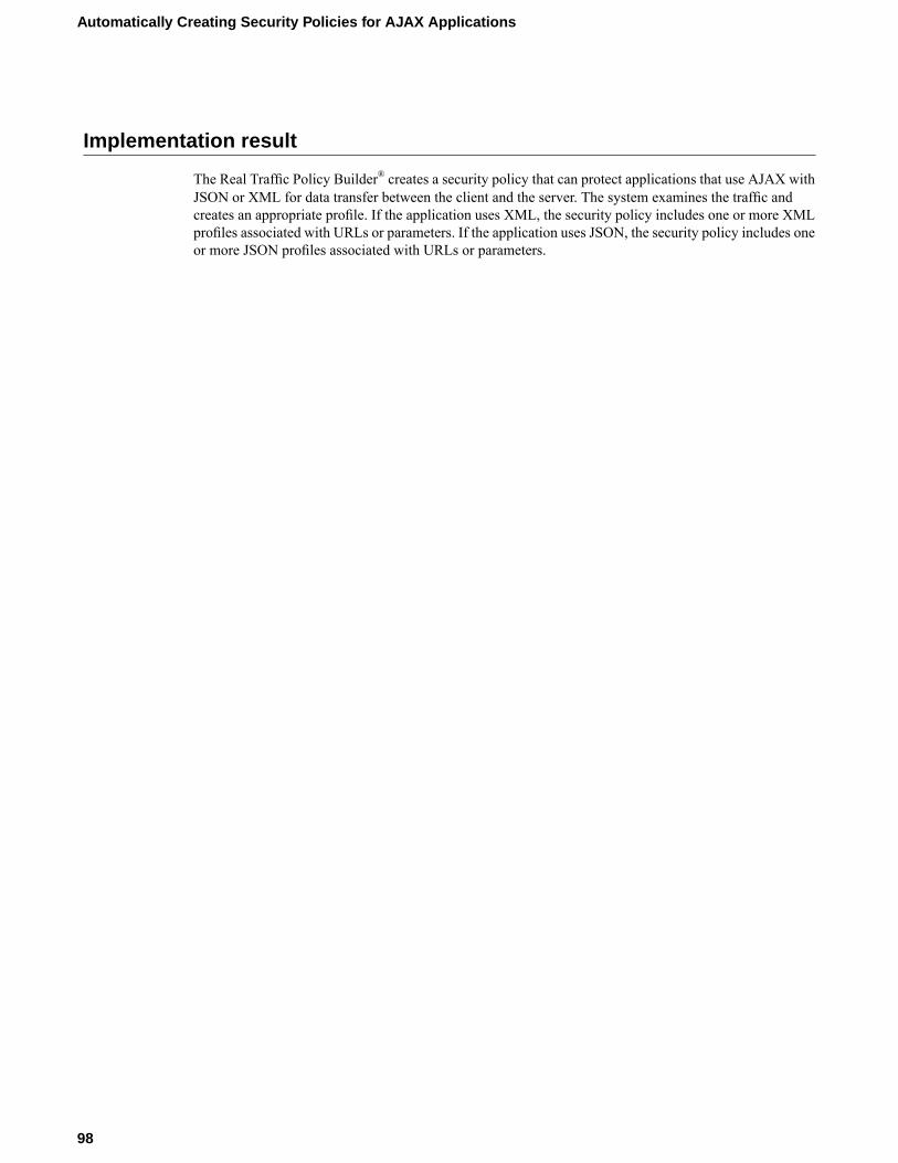
Implementation result
The Real Traffic Policy Builder® creates a security policy that can protect applications that use AJAX withJSON or XML for data transfer between the client and the server. The system examines the traffic andcreates an appropriate profile. If the application uses XML, the security policy includes one or more XMLprofiles associated with URLs or parameters. If the application uses JSON, the security policy includes oneor more JSON profiles associated with URLs or parameters.
98
Automatically Creating Security Policies for AJAX Applications

Chapter
14Adding JSON Support to an Existing Security Policy
• Overview: Adding JSON support to existingsecurity policies
• Implementation result
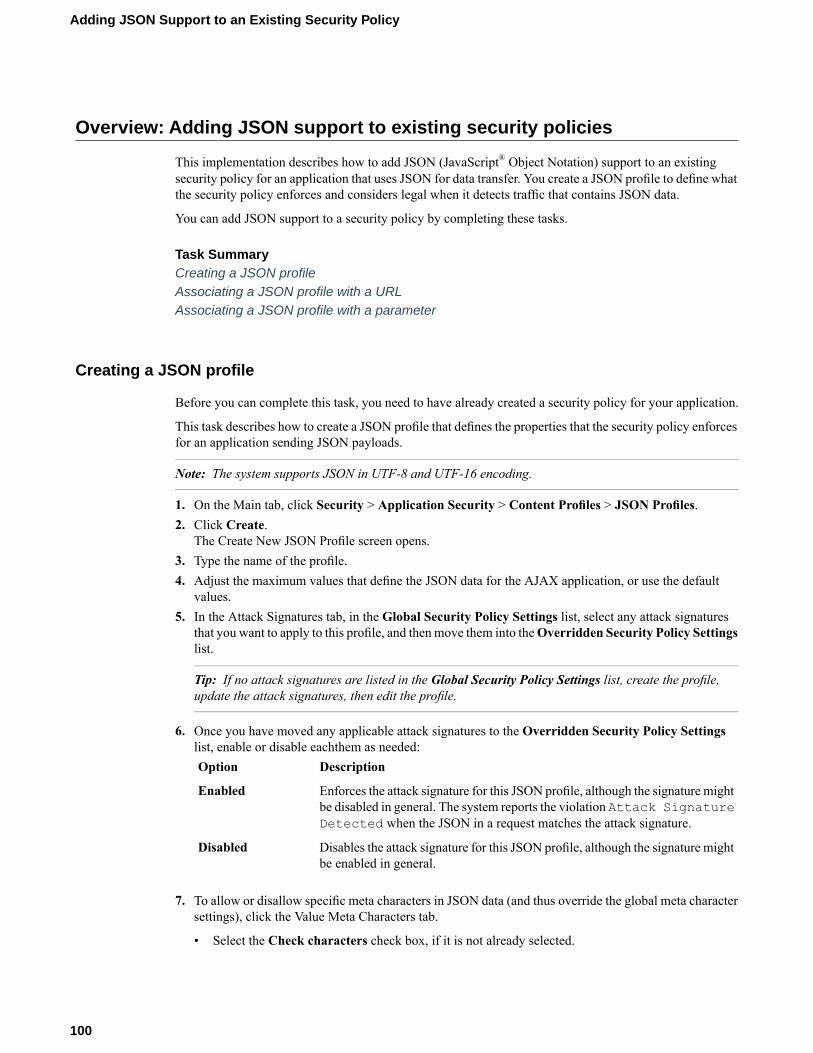
Overview: Adding JSON support to existing security policies
This implementation describes how to add JSON (JavaScript® Object Notation) support to an existingsecurity policy for an application that uses JSON for data transfer. You create a JSON profile to define whatthe security policy enforces and considers legal when it detects traffic that contains JSON data.
You can add JSON support to a security policy by completing these tasks.
Task SummaryCreating a JSON profileAssociating a JSON profile with a URLAssociating a JSON profile with a parameter
Creating a JSON profile
Before you can complete this task, you need to have already created a security policy for your application.
This task describes how to create a JSON profile that defines the properties that the security policy enforcesfor an application sending JSON payloads.
Note: The system supports JSON in UTF-8 and UTF-16 encoding.
1. On the Main tab, click Security > Application Security > Content Profiles > JSON Profiles.2. Click Create.
The Create New JSON Profile screen opens.3. Type the name of the profile.4. Adjust the maximum values that define the JSON data for the AJAX application, or use the default
values.5. In the Attack Signatures tab, in the Global Security Policy Settings list, select any attack signatures
that you want to apply to this profile, and thenmove them into theOverridden Security Policy Settingslist.
Tip: If no attack signatures are listed in the Global Security Policy Settings list, create the profile,update the attack signatures, then edit the profile.
6. Once you have moved any applicable attack signatures to the Overridden Security Policy Settingslist, enable or disable eachthem as needed:
DescriptionOption
Enforces the attack signature for this JSON profile, although the signature mightbe disabled in general. The system reports the violation Attack SignatureDetected when the JSON in a request matches the attack signature.
Enabled
Disables the attack signature for this JSON profile, although the signature mightbe enabled in general.
Disabled
7. To allow or disallow specific meta characters in JSON data (and thus override the global meta charactersettings), click the Value Meta Characters tab.
• Select the Check characters check box, if it is not already selected.
100
Adding JSON Support to an Existing Security Policy
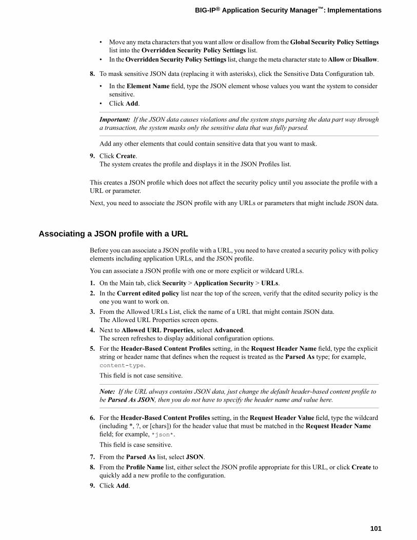
• Move anymeta characters that you want allow or disallow from theGlobal Security Policy Settingslist into the Overridden Security Policy Settings list.
• In theOverridden Security Policy Settings list, change themeta character state toAllow orDisallow.
8. To mask sensitive JSON data (replacing it with asterisks), click the Sensitive Data Configuration tab.
• In the Element Name field, type the JSON element whose values you want the system to considersensitive.
• Click Add.
Important: If the JSON data causes violations and the system stops parsing the data part way througha transaction, the system masks only the sensitive data that was fully parsed.
Add any other elements that could contain sensitive data that you want to mask.
9. Click Create.The system creates the profile and displays it in the JSON Profiles list.
This creates a JSON profile which does not affect the security policy until you associate the profile with aURL or parameter.
Next, you need to associate the JSON profile with any URLs or parameters that might include JSON data.
Associating a JSON profile with a URL
Before you can associate a JSON profile with a URL, you need to have created a security policy with policyelements including application URLs, and the JSON profile.
You can associate a JSON profile with one or more explicit or wildcard URLs.
1. On the Main tab, click Security > Application Security > URLs.2. In the Current edited policy list near the top of the screen, verify that the edited security policy is the
one you want to work on.3. From the Allowed URLs List, click the name of a URL that might contain JSON data.
The Allowed URL Properties screen opens.4. Next to Allowed URL Properties, select Advanced.
The screen refreshes to display additional configuration options.5. For the Header-Based Content Profiles setting, in the Request Header Name field, type the explicit
string or header name that defines when the request is treated as the Parsed As type; for example,content-type.This field is not case sensitive.
Note: If the URL always contains JSON data, just change the default header-based content profile tobe Parsed As JSON, then you do not have to specify the header name and value here.
6. For theHeader-Based Content Profiles setting, in the Request Header Value field, type the wildcard(including *, ?, or [chars]) for the header value that must be matched in the Request Header Namefield; for example, *json*.This field is case sensitive.
7. From the Parsed As list, select JSON.8. From the Profile Name list, either select the JSON profile appropriate for this URL, or click Create to
quickly add a new profile to the configuration.9. Click Add.
101
BIG-IP® Application Security Manager™: Implementations
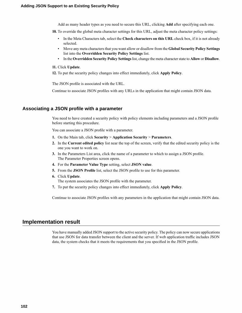
Add as many header types as you need to secure this URL, clicking Add after specifying each one.
10. To override the global meta character settings for this URL, adjust the meta character policy settings:
• In the Meta Characters tab, select the Check characters on this URL check box, if it is not alreadyselected.
• Move anymeta characters that you want allow or disallow from theGlobal Security Policy Settingslist into the Overridden Security Policy Settings list.
• In theOverridden Security Policy Settings list, change themeta character state toAllow orDisallow.
11. Click Update.12. To put the security policy changes into effect immediately, click Apply Policy.
The JSON profile is associated with the URL.
Continue to associate JSON profiles with any URLs in the application that might contain JSON data.
Associating a JSON profile with a parameter
You need to have created a security policy with policy elements including parameters and a JSON profilebefore starting this procedure.
You can associate a JSON profile with a parameter.
1. On the Main tab, click Security > Application Security > Parameters.2. In the Current edited policy list near the top of the screen, verify that the edited security policy is the
one you want to work on.3. In the Parameters List area, click the name of a parameter to which to assign a JSON profile.
The Parameter Properties screen opens.4. For the Parameter Value Type setting, select JSON value.5. From the JSON Profile list, select the JSON profile to use for this parameter.6. Click Update.
The system associates the JSON profile with the parameter.7. To put the security policy changes into effect immediately, click Apply Policy.
Continue to associate JSON profiles with any parameters in the application that might contain JSON data.
Implementation result
You havemanually added JSON support to the active security policy. The policy can now secure applicationsthat use JSON for data transfer between the client and the server. If web application traffic includes JSONdata, the system checks that it meets the requirements that you specified in the JSON profile.
102
Adding JSON Support to an Existing Security Policy
Chapter
15Adding AJAX Blocking Response Behavior to a SecurityPolicy
• Overview: Adding AJAX blocking and loginresponse behavior
• Configuring the blocking response for AJAXapplications
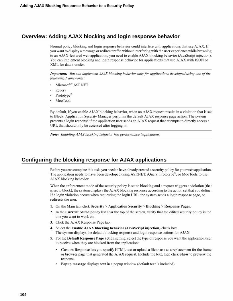
Overview: Adding AJAX blocking and login response behavior
Normal policy blocking and login response behavior could interfere with applications that use AJAX. Ifyou want to display a message or redirect traffic without interfering with the user experience while browsingto an AJAX-featured web application, you need to enable AJAX blocking behavior (JavaScript injection).You can implement blocking and login response behavior for applications that use AJAX with JSON orXML for data transfer.
Important: You can implement AJAX blocking behavior only for applications developed using one of thefollowing frameworks:
• Microsoft® ASP.NET• jQuery• Prototype®
• MooTools
By default, if you enable AJAX blocking behavior, when an AJAX request results in a violation that is setto Block, Application Security Manager performs the default AJAX response page action. The systempresents a login response if the application user sends an AJAX request that attempts to directly access aURL that should only be accessed after logging in.
Note: Enabling AJAX blocking behavior has performance implications.
Configuring the blocking response for AJAX applications
Before you can complete this task, you need to have already created a security policy for your web application.The application needs to have been developed using ASP.NET, jQuery, Prototype®, or MooTools to useAJAX blocking behavior.
When the enforcement mode of the security policy is set to blocking and a request triggers a violation (thatis set to block), the system displays the AJAX blocking response according to the action set that you define.If a login violation occurs when requesting the login URL, the system sends a login response page, orredirects the user.
1. On the Main tab, click Security > Application Security > Blocking > Response Pages.2. In the Current edited policy list near the top of the screen, verify that the edited security policy is the
one you want to work on.3. Click the AJAX Response Page tab.4. Select the Enable AJAX blocking behavior (JavaScript injection) check box.
The system displays the default blocking response and login response actions for AJAX.5. For theDefault Response Page action setting, select the type of response you want the application user
to receive when they are blocked from the application:
• Custom Response lets you specify HTML text or upload a file to use as a replacement for the frameor browser page that generated the AJAX request. Include the text, then click Show to preview theresponse.
• Popup message displays text in a popup window (default text is included).
104
Adding AJAX Blocking Response Behavior to a Security Policy
• Redirect URL redirects the user to the URL you specify. You can also include the support ID. Forexample:http://www.example.com/blocking_page.php?support_id=<%TS.request.ID()%>.
6. For the Login Page Response action, select the type of response (types are the same as for defaultresponse page in Step 5).
7. Click Save.8. To put the security policy changes into effect immediately, click Apply Policy.
105
BIG-IP® Application Security Manager™: Implementations

Chapter
16Securing Base64-Encoded Parameters
• Overview: Securing Base64-EncodedParameters
• Adding base64 decoding to a new user-inputparameter
• Adding base64 decoding to an existinguser-input parameter
Overview: Securing Base64-Encoded Parameters
Base64 encoding is a convenient encoding method that uses a compact presentation, and is relativelyunreadable to the casual observer. Many applications apply base64 encoding to binary data, for inclusionin URLs or in hidden web form fields. Unfortunately, it is also possible to mask application attacks inbase64-encoded data. To provide better security for applications that use base64 encoding, ApplicationSecurity Manager™ can decode user-input parameter values that are base64-encoded.
Adding base64 decoding to a new user-input parameter
When enabled, the system can apply base64 decoding for a user-input parameter. If the decoding is successful,the system applies the parameter checks specified in the security policy. If the decoding is not successful,the system issues the Illegal base64 encoded value violation and responds to the offendingrequest according the associated blocking policy.
1. On the Main tab, click Security > Application Security > Parameters > Parameters List.2. On the Main tab, click Security > Application Security > Parameters.3. Type the name for the new explicit parameter.4. For the Parameter Level setting, select where in a request the parameter is located.
DescriptionOption
The parameter can occur anywhere and is not associated with a specific URLor flow.
Global
The parameter occurs in the specific URL that you provide.URL
The parameter occurs in the specific entry point URL or referrer URL thatyou provide.
Flow
5. Leave the Perform Staging check box selected if you want the system to evaluate traffic before enforcingthis parameter.Staging helps reduce the occurrence of false positives.
6. For the Parameter Value Type setting, select User-input value.7. On the Data Type tab, for the Data Type setting, select either Alpha-Numeric or File Upload.8. Select the Base64 Decoding check box if you want the system to apply base64 decoding to values for
this parameter.9. Configure any other properties that apply to this new parameter.10. Click Create.
The screen refreshes, and the new parameter appears in the parameters list.11. To put the security policy changes into effect immediately, click Apply Policy.
108
Securing Base64-Encoded Parameters
Adding base64 decoding to an existing user-input parameter
When enabled, the system can decode base64 encoding in a user-input parameter. If the decoding is successful,the system applies the parameter checks specified in the security policy. If the decoding is not successful,the system issues the Illegal base64 encoded value violation and responds to the offendingrequest according to the associated blocking policy.
1. On the Main tab, click Security > Application Security > Parameters > Parameters List.2. In the Parameters List filter, select Parameter Value Type in the left list, User-input value in right
list, and click Go.The screen refreshes and lists only user-input parameters.
3. In the Parameter Name column, click the name of the parameter to which you want to add base64decoding.The Parameter Properties screen opens.
4. On the Data Type tab, select the Base64 Decoding check box so the system applies base64 decodingto values for this parameter.
Note: The base64 decoding setting is available only for user-input parameters of the alpha-numeric orfile upload data type.
5. Click Update.The screen refreshes, and displays the parameters list.
6. To put the security policy changes into effect immediately, click Apply Policy.
109
BIG-IP® Application Security Manager™: Implementations

Chapter
17Securing Web Applications Created with Google Web Toolkit
• Overview: Securing Java web applicationscreated with Google Web Toolkit elements
• Implementation result
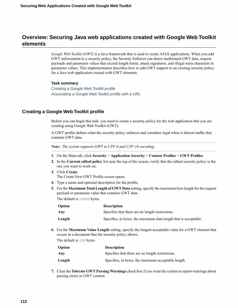
Overview: Securing Java web applications created with Google Web Toolkitelements
Google Web Toolkit (GWT) is a Java framework that is used to create AJAX applications. When you addGWT enforcement to a security policy, the Security Enforcer can detect malformed GWT data, requestpayloads and parameter values that exceed length limits, attack signatures, and illegal meta characters inparameter values. This implementation describes how to add GWT support to an existing security policyfor a Java web application created with GWT elements.
Task summaryCreating a Google Web Toolkit profileAssociating a Google Web Toolkit profile with a URL
Creating a Google Web Toolkit profile
Before you can begin this task, you need to create a security policy for the web application that you arecreating using Google Web Toolkit (GWT).
A GWT profile defines what the security policy enforces and considers legal when it detects traffic thatcontains GWT data.
Note: The system supports GWT in UTF-8 and UTF-16 encoding.
1. On the Main tab, click Security > Application Security > Content Profiles > GWT Profiles.2. In the Current edited policy list near the top of the screen, verify that the edited security policy is the
one you want to work on.3. Click Create.
The Create New GWT Profile screen opens.4. Type a name and optional description for the profile.5. For theMaximumTotal Length of GWTData setting, specify the maximum byte length for the request
payload or parameter value that contains GWT data.The default is 10000 bytes.
DescriptionOptionSpecifies that there are no length restrictions.Any
Specifies, in bytes, the maximum data length that is acceptable.Length
6. For theMaximum Value Length setting, specify the longest acceptable value for a GWT element thatoccurs in a document that the security policy allows.The default is 100 bytes.
DescriptionOptionSpecifies that there are no length restrictions.Any
Specifies, in bytes, the maximum acceptable length.Length
7. Clear the Tolerate GWTParsingWarnings check box if you want the system to report warnings aboutparsing errors in GWT content.
112
Securing Web Applications Created with Google Web Toolkit
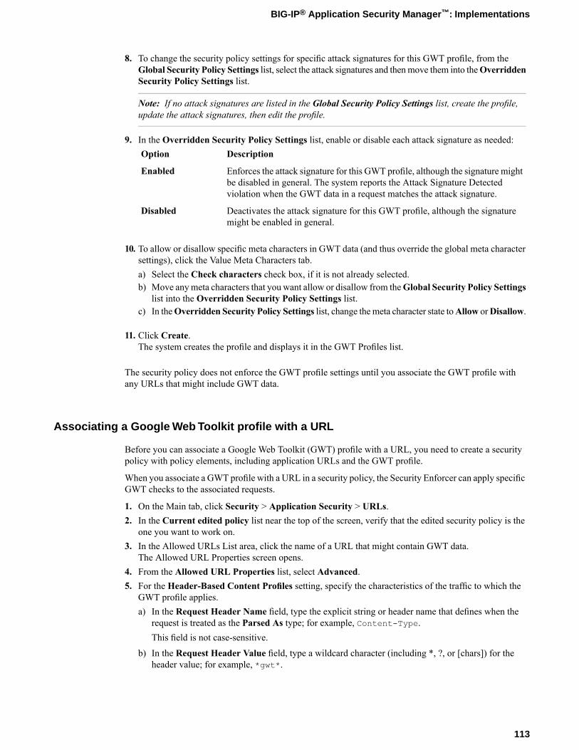
8. To change the security policy settings for specific attack signatures for this GWT profile, from theGlobal Security Policy Settings list, select the attack signatures and thenmove them into theOverriddenSecurity Policy Settings list.
Note: If no attack signatures are listed in the Global Security Policy Settings list, create the profile,update the attack signatures, then edit the profile.
9. In the Overridden Security Policy Settings list, enable or disable each attack signature as needed:DescriptionOption
Enforces the attack signature for this GWT profile, although the signature mightbe disabled in general. The system reports the Attack Signature Detectedviolation when the GWT data in a request matches the attack signature.
Enabled
Deactivates the attack signature for this GWT profile, although the signaturemight be enabled in general.
Disabled
10. To allow or disallow specific meta characters in GWT data (and thus override the global meta charactersettings), click the Value Meta Characters tab.a) Select the Check characters check box, if it is not already selected.b) Move anymeta characters that you want allow or disallow from theGlobal Security Policy Settings
list into the Overridden Security Policy Settings list.c) In theOverridden Security Policy Settings list, change themeta character state toAllow orDisallow.
11. Click Create.The system creates the profile and displays it in the GWT Profiles list.
The security policy does not enforce the GWT profile settings until you associate the GWT profile withany URLs that might include GWT data.
Associating a Google Web Toolkit profile with a URL
Before you can associate a Google Web Toolkit (GWT) profile with a URL, you need to create a securitypolicy with policy elements, including application URLs and the GWT profile.
When you associate a GWT profile with a URL in a security policy, the Security Enforcer can apply specificGWT checks to the associated requests.
1. On the Main tab, click Security > Application Security > URLs.2. In the Current edited policy list near the top of the screen, verify that the edited security policy is the
one you want to work on.3. In the Allowed URLs List area, click the name of a URL that might contain GWT data.
The Allowed URL Properties screen opens.4. From the Allowed URL Properties list, select Advanced.5. For the Header-Based Content Profiles setting, specify the characteristics of the traffic to which the
GWT profile applies.a) In the Request Header Name field, type the explicit string or header name that defines when the
request is treated as the Parsed As type; for example, Content-Type.This field is not case-sensitive.
b) In the Request Header Value field, type a wildcard character (including *, ?, or [chars]) for theheader value; for example, *gwt*.
113
BIG-IP® Application Security Manager™: Implementations
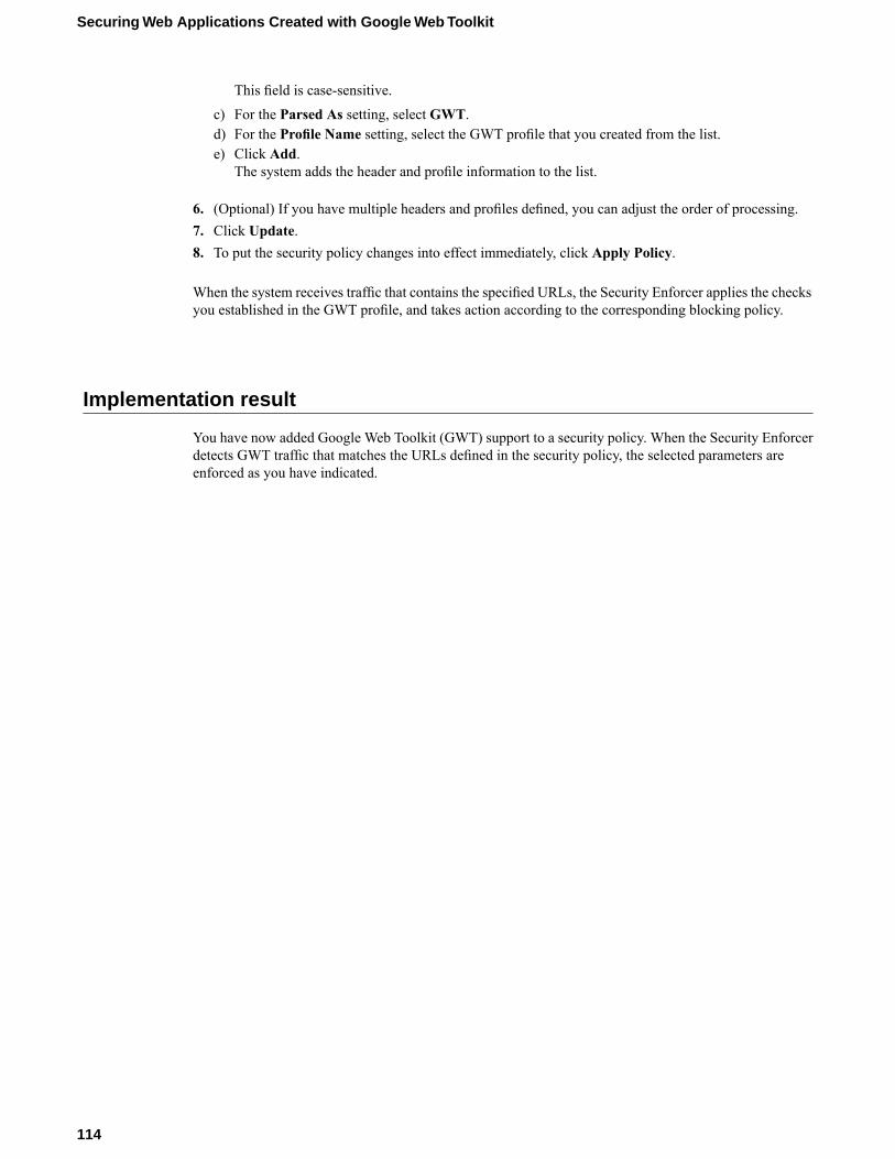
This field is case-sensitive.
c) For the Parsed As setting, select GWT.d) For the Profile Name setting, select the GWT profile that you created from the list.e) Click Add.
The system adds the header and profile information to the list.
6. (Optional) If you have multiple headers and profiles defined, you can adjust the order of processing.7. Click Update.8. To put the security policy changes into effect immediately, click Apply Policy.
When the system receives traffic that contains the specified URLs, the Security Enforcer applies the checksyou established in the GWT profile, and takes action according to the corresponding blocking policy.
Implementation result
You have now added Google Web Toolkit (GWT) support to a security policy. When the Security Enforcerdetects GWT traffic that matches the URLs defined in the security policy, the selected parameters areenforced as you have indicated.
114
Securing Web Applications Created with Google Web Toolkit
Chapter
18Preventing DoS Attacks for Layer 7 Traffic
• What is a DoS attack?• About recognizing DoS attacks• About configuring TPS-based DoS protection• About configuring latency-based DoS
protection• Overview: Preventing DoS attacks for Layer
7 traffic• Implementation Result
What is a DoS attack?
A denial-of-service attack (DoS attack) makes a computer resource unavailable to its intended users, orobstructs the communication media between the intended users and the victim so that they can no longercommunicate adequately. Perpetrators of DoS attacks typically target sites or services, such as banks, creditcard payment gateways, and e-commerce web sites.
Denial-of-service attacks are also known as HTTP-GET attacks or page flood attacks.
HTTP-GET attacksThe attacks are initiated either from a single user (single IP address) or from thousands of computers(distributed DoS attack), which overwhelms the target system.
Page flood attacksPage flood attacks (or HTTP flood attacks) may resemble the patterns of normal web surfing, makingit harder for automated tools to differentiate between legitimate web traffic and an attempted attack.
About recognizing DoS attacks
Application Security Manager™ determines that traffic is a DoS attack based on calculations for transactionrates on the client side (TPS-based) or latency on the server side (latency-based). You can specify thecalculations that you want the system to use.
Note: You can set up both methods of detection to work independently or you can set them up to workconcurrently to simultaneously detect attacks on both the client side and server side.
You can view details about DoS attacks that the system detected and logged. You can also configure remotelogging support for DoS attacks when creating a logging profile.
About configuring TPS-based DoS protection
When setting up DoS protection, you can configure the system to prevent DoS attacks based on transactionrates (TPS-based anomaly detection). If you choose TPS-based anomaly protection, the system detects DoSattacks from the client side using the following calculations:
Transaction rate during detection intervalThe average number of requests per second sent for a specific URL, or by a specific IP address. Everysecond, the system calculates the average TPS for the last minute.
Note: The averages for IP address and URL counts are done for each virtual server, not each DoS L7profile, in case one DoS L7 profile is assigned to more than one virtual server.
Transaction rate during history intervalThe average number of requests per second sent for a specific URL, or by a specific IP address. Thesystem calculates this number every minute.
116
Preventing DoS Attacks for Layer 7 Traffic
If the ratio of the transaction rate during the detection interval to the transaction rate during the historyinterval is greater than the percentage indicated in the TPS increased by setting, the system considers theURL to be under attack, or the IP address to be suspicious.
About configuring latency-based DoS protection
When setting up DoS protection, you can configure the system to prevent DoS attacks based on serverlatency (latency-based anomaly detection). If you choose latency-based anomaly protection, the systemdetects DoS attacks from the server side using the following calculations:
Latency during detection intervalThe average time it takes for the system to respond to a request for a specific URL over the last minute.The system calculates this number every second.
Note: The averages for IP address and URL counts are done for each virtual server, not each DoS L7profile, in case one DoS L7 profile is assigned to more than one virtual server.
Latency during history intervalThe average time it takes for the system to respond to a request for a specific URL over the last hour.The system calculates this number every minute.
If the ratio of the latency during the detection interval to the latency during the history interval is greaterthan the percentage in the Latency increased by setting, the system detects that this URL is under attack.
Overview: Preventing DoS attacks for Layer 7 traffic
You can configure the Application Security Manager™ to protect against L7 DoS attacks. Depending onyour configuration, the system detects DoS attacks based on transactions per second (TPS) on the clientside, or server latency, or both.
You configure DoS protection for Layer 7 by creating a DoS profile with Application Security enabled.You then associate the DoS profile with one or more virtual servers representing applications that you wantto protect. DoS protection is not part of a security policy.
Task SummaryConfiguring Layer 7 DoS protectionConfiguring TPS-based DoS protection settingsConfiguring latency-based DoS protectionAssociating a DoS profile with a virtual serverDisplaying DoS event logsViewing L7 DoS attack reports
Configuring Layer 7 DoS protection
You can configure Application Security Manager™ to mitigate DoS attacks and increase system security.
1. On the Main tab, click Security > DoS Protection.
117
BIG-IP® Application Security Manager™: Implementations
The DoS Profiles list screen opens.2. Click Create.
The Create New DoS Profile screen opens.3. In the Profile Name field, type the name for the profile.4. Select the Application Security check box.
The screen refreshes and displays additional configuration settings.5. If you have written an application DoS iRule to specify how the system handles a DoS attack and recovers
afterwards, you may select the Trigger iRule setting.6. If you want to set up DoS protection from the client side, in the TPS-based Anomaly area, select an
Operation Mode and set up TPS-based DoS protection.Another task describes how to configure the settings.
7. If you want to set up DoS protection from the server side, in the Latency-based Anomaly area, selectan Operation Mode and set up latency-based DoS protection.Another task describes how to configure the settings.
8. To omit certain addresses, for the IP Address Whitelist setting, type IP addresses or subnets that donot need to be examined for DoS attacks, and click Add.
Note: You can add up to twenty IP addresses.
9. Click Finished to save the DoS profile.
You have created a DoS profile.
Next, configure TPS-based or latency-based DoS protection settings, or both.
Configuring TPS-based DoS protection settings
You can configure Application Security Manager™ to mitigate DoS attacks based on transaction rates usingTPS-based DoS protection.
1. On the Main tab, click Security > DoS Protection.The DoS Profiles list screen opens.
2. Click the name of an existing DoS profile (or create a new one).The DoS Profile Properties screen opens.
3. Select the Application Security check box.The screen refreshes and displays additional configuration settings.
4. In the TPS-based Anomaly area, for Operation Mode, select an operation mode.DescriptionOption
Displays information about DoS attacks on the DoS: Application reportingscreen but does not block requests.
Transparent
Drops connections coming from an attacking IP address and requests toattacked URLs. Also displays information about DoS attacks on the DoS:Application reporting screen.
Blocking
The screen refreshes to display additional configuration settings when you select an operation mode.5. For the Prevention Policy setting, select one or more options to determine how the system handles a
DoS attack.
118
Preventing DoS Attacks for Layer 7 Traffic
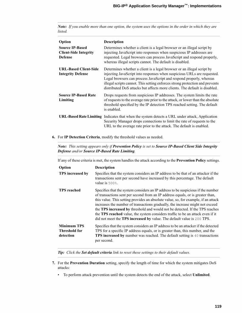
Note: If you enable more than one option, the system uses the options in the order in which they arelisted.
DescriptionOptionDetermines whether a client is a legal browser or an illegal script byinjecting JavaScript into responses when suspicious IP addresses are
Source IP-BasedClient-Side IntegrityDefense requested. Legal browsers can process JavaScript and respond properly,
whereas illegal scripts cannot. The default is disabled.
Determines whether a client is a legal browser or an illegal script byinjecting JavaScript into responses when suspicious URLs are requested.
URL-Based Client-SideIntegrity Defense
Legal browsers can process JavaScript and respond properly, whereasillegal scripts cannot. This setting enforces strong protection and preventsdistributed DoS attacks but affects more clients. The default is disabled.
Drops requests from suspicious IP addresses. The system limits the rateof requests to the average rate prior to the attack, or lower than the absolute
Source IP-Based RateLimiting
threshold specified by the IP detection TPS reached setting. The defaultis enabled.
Indicates that when the system detects a URL under attack, ApplicationSecurity Manager drops connections to limit the rate of requests to theURL to the average rate prior to the attack. The default is enabled.
URL-BasedRateLimiting
6. For IP Detection Criteria, modify the threshold values as needed.
Note: This setting appears only if Prevention Policy is set to Source IP-Based Client Side IntegrityDefense and/or Source IP-Based Rate Limiting.
If any of these criteria is met, the system handles the attack according to the Prevention Policy settings.
DescriptionOptionSpecifies that the system considers an IP address to be that of an attacker if thetransactions sent per second have increased by this percentage. The defaultvalue is 500%.
TPS increased by
Specifies that the system considers an IP address to be suspicious if the numberof transactions sent per second from an IP address equals, or is greater than,
TPS reached
this value. This setting provides an absolute value, so, for example, if an attackincreases the number of transactions gradually, the increase might not exceedthe TPS increased by threshold and would not be detected. If the TPS reachesthe TPS reached value, the system considers traffic to be an attack even if itdid not meet the TPS increased by value. The default value is 200 TPS.
Specifies that the system considers an IP address to be an attacker if the detectedTPS for a specific IP address equals, or is greater than, this number, and the
Minimum TPSThreshold fordetection TPS increased by number was reached. The default setting is 40 transactions
per second.
Tip: Click the Set default criteria link to reset these settings to their default values.
7. For the Prevention Duration setting, specify the length of time for which the system mitigates DoSattacks:
• To perform attack prevention until the system detects the end of the attack, select Unlimited.
119
BIG-IP® Application Security Manager™: Implementations
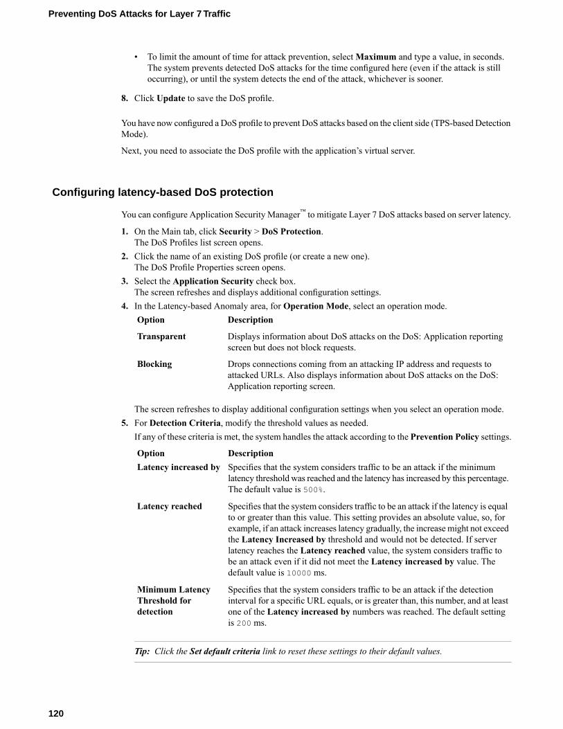
• To limit the amount of time for attack prevention, selectMaximum and type a value, in seconds.The system prevents detected DoS attacks for the time configured here (even if the attack is stilloccurring), or until the system detects the end of the attack, whichever is sooner.
8. Click Update to save the DoS profile.
You have now configured a DoS profile to prevent DoS attacks based on the client side (TPS-based DetectionMode).
Next, you need to associate the DoS profile with the application’s virtual server.
Configuring latency-based DoS protection
You can configure Application Security Manager™ to mitigate Layer 7 DoS attacks based on server latency.
1. On the Main tab, click Security > DoS Protection.The DoS Profiles list screen opens.
2. Click the name of an existing DoS profile (or create a new one).The DoS Profile Properties screen opens.
3. Select the Application Security check box.The screen refreshes and displays additional configuration settings.
4. In the Latency-based Anomaly area, for Operation Mode, select an operation mode.DescriptionOption
Displays information about DoS attacks on the DoS: Application reportingscreen but does not block requests.
Transparent
Drops connections coming from an attacking IP address and requests toattacked URLs. Also displays information about DoS attacks on the DoS:Application reporting screen.
Blocking
The screen refreshes to display additional configuration settings when you select an operation mode.5. For Detection Criteria, modify the threshold values as needed.
If any of these criteria is met, the system handles the attack according to the Prevention Policy settings.
DescriptionOptionSpecifies that the system considers traffic to be an attack if the minimumlatency threshold was reached and the latency has increased by this percentage.The default value is 500%.
Latency increased by
Specifies that the system considers traffic to be an attack if the latency is equalto or greater than this value. This setting provides an absolute value, so, for
Latency reached
example, if an attack increases latency gradually, the increasemight not exceedthe Latency Increased by threshold and would not be detected. If serverlatency reaches the Latency reached value, the system considers traffic tobe an attack even if it did not meet the Latency increased by value. Thedefault value is 10000 ms.
Specifies that the system considers traffic to be an attack if the detectioninterval for a specific URL equals, or is greater than, this number, and at least
Minimum LatencyThreshold fordetection one of the Latency increased by numbers was reached. The default setting
is 200 ms.
Tip: Click the Set default criteria link to reset these settings to their default values.
120
Preventing DoS Attacks for Layer 7 Traffic
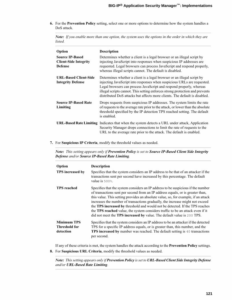
6. For the Prevention Policy setting, select one or more options to determine how the system handles aDoS attack.
Note: If you enable more than one option, the system uses the options in the order in which they arelisted.
DescriptionOptionDetermines whether a client is a legal browser or an illegal script byinjecting JavaScript into responses when suspicious IP addresses are
Source IP-BasedClient-Side IntegrityDefense requested. Legal browsers can process JavaScript and respond properly,
whereas illegal scripts cannot. The default is disabled.
Determines whether a client is a legal browser or an illegal script byinjecting JavaScript into responses when suspicious URLs are requested.
URL-Based Client-SideIntegrity Defense
Legal browsers can process JavaScript and respond properly, whereasillegal scripts cannot. This setting enforces strong protection and preventsdistributed DoS attacks but affects more clients. The default is disabled.
Drops requests from suspicious IP addresses. The system limits the rateof requests to the average rate prior to the attack, or lower than the absolute
Source IP-Based RateLimiting
threshold specified by the IP detection TPS reached setting. The defaultis enabled.
Indicates that when the system detects a URL under attack, ApplicationSecurity Manager drops connections to limit the rate of requests to theURL to the average rate prior to the attack. The default is enabled.
URL-BasedRateLimiting
7. For Suspicious IP Criteria, modify the threshold values as needed.
Note: This setting appears only if Prevention Policy is set to Source IP-Based Client Side IntegrityDefense and/or Source IP-Based Rate Limiting.
DescriptionOptionSpecifies that the system considers an IP address to be that of an attacker if thetransactions sent per second have increased by this percentage. The defaultvalue is 500%.
TPS increased by
Specifies that the system considers an IP address to be suspicious if the numberof transactions sent per second from an IP address equals, or is greater than,
TPS reached
this value. This setting provides an absolute value, so, for example, if an attackincreases the number of transactions gradually, the increase might not exceedthe TPS increased by threshold and would not be detected. If the TPS reachesthe TPS reached value, the system considers traffic to be an attack even if itdid not meet the TPS increased by value. The default value is 200 TPS.
Specifies that the system considers an IP address to be an attacker if the detectedTPS for a specific IP address equals, or is greater than, this number, and the
Minimum TPSThreshold fordetection TPS increased by number was reached. The default setting is 40 transactions
per second.
If any of these criteria is met, the system handles the attack according to the Prevention Policy settings.8. For Suspicious URL Criteria, modify the threshold values as needed.
Note: This setting appears only if Prevention Policy is set toURL-Based Client Side Integrity Defenseand/or URL-Based Rate Limiting.
121
BIG-IP® Application Security Manager™: Implementations

DescriptionOption
Specifies that the system considers a URL to be that of an attacker if thetransactions sent per second sent to the URL have increased by this percentage.The default value is 500%.
TPS increased by
Specifies that the system considers a URL to be suspicious if the number oftransactions sent per second to the URL is equal to or greater than this value.
TPS reached
This setting provides an absolute value, so, for example, if an attack increasesthe number of transactions gradually, the increase might not exceed the TPSincreased by threshold and would not be detected. If the TPS reaches the TPSreached value, the system considers traffic to be an attack even if it did notmeet the TPS increased by value. The default value is 1000 TPS.
Specifies that the system considers a URL to be an attacker if the detected TPSfor a specific URL equals, or is greater than, this number, and theTPS increasedby number was reached. The default setting is 40 transactions per second.
Minimum TPSThreshold fordetection
If any of these criteria is met, the system handles the attack according to the Prevention Policy settings.9. For the Prevention Duration setting, specify the length of time for which the system mitigates DoS
attacks:
• To perform attack prevention until the system detects the end of the attack, select Unlimited.• To limit the amount of time for attack prevention, selectMaximum and type a value, in seconds.
The system prevents detected DoS attacks for the time configured here (even if the attack is stilloccurring), or until the system detects the end of the attack, whichever is sooner.
10. Click Update to save the DoS profile.
You have now configured a DoS profile to prevent DoS attacks based on server latency.
Next, associate the DoS profile with the application’s virtual server.
Associating a DoS profile with a virtual server
You must first create a DoS profile separately, to configure denial-of-service protection for applications,the DNS protocol, or the SIP protocol.
You add denial-of-service protection to a virtual server to provide enhanced protection from DoS attacks,and track anomalous activity on the BIG-IP® system.
1. On the Main tab, click Local Traffic > Virtual Servers.The Virtual Server List screen opens.
2. Click the name of the virtual server you want to modify.3. For the Destination setting, select Host and in the Address field, type the IP address for the virtual
server.4. From the Security menu, choose Policies.5. To enable denial-of-service protection, from the DoS Protection Profile list, select Enabled, and then,
from the Profile list, select the DoS profile to associate with the virtual server.6. Click Update to save the changes.
DoS protection is now enabled, and the DoS Protection profile is associated with the virtual server.Overview: Preventing DoS attacks for Layer 7 trafficConfiguring latency-based DoS protectionDisplaying DoS event logs
122
Preventing DoS Attacks for Layer 7 Traffic
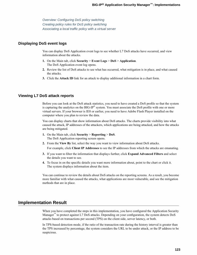
Overview: Configuring DoS policy switchingCreating policy rules for DoS policy switchingAssociating a local traffic policy with a virtual server
Displaying DoS event logs
You can display DoS Application event logs to see whether L7 DoS attacks have occurred, and viewinformation about the attacks.
1. On the Main tab, click Security > Event Logs > DoS > Application.The DoS Application event log opens.
2. Review the list of DoS attacks to see what has occurred, what mitigation is in place, and what causedthe attacks.
3. Click the Attack ID link for an attack to display additional information in a chart form.
Viewing L7 DoS attack reports
Before you can look at the DoS attack statistics, you need to have created a DoS profile so that the systemis capturing the analytics on the BIG-IP® system. You must associate the DoS profile with one or morevirtual servers. If your browser is IE8 or earlier, you need to have Adobe Flash Player installed on thecomputer where you plan to review the data.
You can display charts that show information about DoS attacks. The charts provide visibility into whatcaused the attack, IP addresses of the attackers, which applications are being attacked, and how the attacksare being mitigated.
1. On the Main tab, click Security > Reporting > DoS.The DoS Application reporting screen opens.
2. From the View By list, select the way you want to view information about DoS attacks.For example, click Client IP Addresses to see the IP addresses from which the attacks are emanating.
3. If you want to filter the information that displays further, click Expand Advanced Filters and selectthe details you want to see.
4. To focus in on the specific details you want more information about, point to the chart or click it.The system displays information about the item.
You can continue to review the details about DoS attacks on the reporting screens. As a result, you becomemore familiar with what caused the attacks, what applications are most vulnerable, and see the mitigationmethods that are in place.
Implementation Result
When you have completed the steps in this implementation, you have configured the Application SecurityManager™ to protect against L7 DoS attacks. Depending on your configuration, the system detects DoSattacks based on transactions per second (TPS) on the client side, server latency, or both.
In TPS-based detection mode, if the ratio of the transaction rate during the history interval is greater thanthe TPS increased by percentage, the system considers the URL to be under attack, or the IP address to besuspicious.
123
BIG-IP® Application Security Manager™: Implementations

In latency-based detection mode, if the ratio of the transaction rate during the history interval is greater thanthe Latency increased by percentage, the system considers the URL to be under attack, or the IP address tobe suspicious.
If you chose the blocking operation mode, the system drops requests from suspicious IP addresses andURLs. If using the transparent operation mode, the system reports DoS attacks but does not block them.
After traffic is flowing to the system, you can check whether DoS attacks are being prevented, and investigatethem by viewing DoS event logs and reports.
124
Preventing DoS Attacks for Layer 7 Traffic
Chapter
19Configuring DoS Policy Switching
• About DoS protection and local traffic policies• Overview: Configuring DoS policy switching• Implementation results
About DoS protection and local traffic policies
To provide additional flexibility for configuring DoS protection, you can use local traffic policies togetherwith DoS protection. The advantage of creating local traffic policies is that you can apply multiple DoSprotection policies to different types of traffic, using distinct DoS profiles. However, you need to be awareof certain considerations when using this method.
Local traffic policies can include multiple rules. Each rule consists of a condition and a set of actions to beperformed if the respective condition holds. So you can create a local traffic policy that controls Layer 7DoS protection and includes multiple rules. If you do, every rule must include one of the following Layer7 DoS actions:
• Enable DoS protection using the default DoS profile (/Common/dos)• Enable DoS protection from a specific DoS profile• Disable DoS protection
Important: Make sure that the local traffic policy with DoS protection includes a default rule with nocondition that applies to traffic that does not match any other rule. In addition, be sure that each rule(including the default one), has an L7 DoS action in it, possibly in addition to other actions.
A default rule is required because the local traffic policy action applies not only to the request that matchedthe condition, but also to the following requests in the same TCP connection, even if they do not match thecondition that triggered the action unless subsequent requests on the same connection match a different rulewith a different L7 DoS action.
This requirement ensures that every request will match some rule (even the default one), and will trigger areasonable Layer 7 DoS action. This way a request will not automatically enforce the action of the previousrequest on the same connection, which can yield unexpected results.
A typical action for the default rule in case of Layer 7 DoS is to create a rule with no condition and simplyenable DoS protection. In this case, the action the rule takes is to use the DoS policy attached to the virtualserver. In the example of configuring DoS policy switching, the third rule, others, is the default rule.
Overview: Configuring DoS policy switching
You can configure the BIG-IP® system to protect against Layer 7 DoS attacks applying unique profiles indifferent situations, or on different types of traffic.
This implementation provides an example where you configure DoS protection for Layer 7 by creating twoDoS profiles with Application Security enabled. You then associate the default DoS profile with a virtualserver representing the application that you want to protect. You also create a local traffic policy with rulesthat assign different DoS protections depending on the traffic. Then you associate the local traffic policywith the virtual server.
This example divides traffic into three categories:
• Employees: A unique DoS profile, assigned to employees, reports DoS attacks but does not dropconnections when there is an attack.
• Internal users: No DoS protection is applied to internal users.• Others: The strictest DoS protection is applied using the default DoS profile for all other users; the
system blocks DoS attacks that occur on other traffic.
126
Configuring DoS Policy Switching
Many other options are available for configuring DoS policy switching. This is simply one way to illustratehow you can configure multiple DoS protections using a local traffic policy to determine different conditionsand actions. By following the steps in this example, you can see the other options that are available on thescreens, and can adjust the example for your needs.
Task SummaryCreating a DoS profile for Layer 7 trafficModifying the default DoS profileCreating a local traffic policy for DoS policy switchingCreating policy rules for DoS policy switchingAssociating a DoS profile with a virtual serverAssociating a local traffic policy with a virtual server
Creating a DoS profile for Layer 7 traffic
To define the circumstances under which the system considers traffic to be a Denial of Service (DoS attack),you create a DoS profile. For the DoS policy switching example, you can create a special DoS profile, foremployees, that does not block traffic. It only reports the DoS attack.
1. On the Main tab, click Security > DoS Protection.The DoS Profiles list screen opens.
2. Click Create.The Create New DoS Profile screen opens.
3. In the Profile Name field, typeemployee_l7dos_profile for the profile name in this example.4. Select the Application Security check box.
The screen refreshes and displays additional configuration settings.5. In the TPS-based Anomaly area, for Operation Mode, select Transparent.
When the system detects a DoS attack, it displays the attack data on the Reporting DoS Attacks screen.
6. Use the default values for the other settings.7. Click Finished to save the DoS profile.
You have now created a simple DoS profile to report DoS attacks based on transaction rates using TPS-basedDoS protection.
Modifying the default DoS profile
The BIG-IP® system includes a default DoS profile that you can modify to specify when to use DoSprotection. For the DoS policy switching example, you can modify the default DoS profile and use it forpeople other than employees or internal users who are accessing applications. This example creates a strictdefault DoS profile that drops requests considered to be an attack.
1. On the Main tab, click Security > DoS Protection.The DoS Profiles list screen opens.
2. Click the profile called dos.The DoS Profile Properties screen opens.
3. Select the Application Security check box.The screen refreshes and displays additional configuration settings.
4. In the TPS-based Anomaly area, for Operation Mode, select Blocking.
127
BIG-IP® Application Security Manager™: Implementations
5. In the Latency-based Anomaly area, for Operation Mode, select Blocking.6. Use the default values for the other settings.7. Click Finished to save the DoS profile.
You have nowmodified the default DoS profile that will be used for people other than employees or internalusers. For these users, the system drops connections from attacking IP addresses, and for requests directedto attacked URLs.
Creating a local traffic policy for DoS policy switching
You can create a local traffic policy to impose different levels of DoS protection on distinct types of Layer7 traffic.
1. On the Main tab, click Local Traffic > Policies.2. Click Create.
The New Policy screen opens.3. In the Name field, type a name for the local traffic policy.4. From the Strategy list, select first-match.5. In the Requires setting, move http from the Available to the Selected list.6. In the Controls setting, move l7dos from the Available to the Selected list.7. Click Finished to save the local traffic policy.
You have now created a local traffic policy that controls Layer 7 DoS.
Next, you need to add rules to the local traffic policy to specify the DoS protection that should occur fordifferent types of Layer 7 traffic.
Creating policy rules for DoS policy switching
You can add rules to define conditions and perform specific actions for different types of Layer 7 traffic.This example creates three rules to implement different DoS protection for employees, for internal personnel,and for others.
1. On the Main tab, click Local Traffic > Policies.2. Click the name of the local traffic policy that controls Layer 7 DoS.3. In the Rules area, click Add to create a rule that defines DoS protection for employees.4. In the Rule field, type the name employees.5. In the Manage Conditions area, define the employee traffic this rule applies to; specify the following
values, and use the default values for the rest.a) From the Operand list, select http-host.b) From theCondition list, select ends_with; then, in the field below, type employees.my_host.com
and click Add.c) Click Add Condition.
6. In the Manage Actions area, define DoS protection to apply to employees; specify the following valuesand use the default values for the rest.a) From the Target list, select l7dos.
Event is set to request, Action is set to enable, and from_profile is set to the default DoS profile,/Common/dos.
128
Configuring DoS Policy Switching
b) To specify a unique DoS profile for employees, after from_profile, select employee_l7dos_profile,then click Add.
c) Click Add Action.
7. Click Finished to add the rule to the local traffic policy.8. Click Add to create a second rule, and call it internal.9. In the Manage Conditions area, define the internal traffic; specify the following values and use the
default values for the rest.a) From the Operand list, select http-host.b) From theCondition list, select ends_with; then, in the field below, type internal.my_host.com
and click Add.c) Click Add Condition.
10. In the Manage Actions area, disable DoS protection for internal traffic; specify the following values anduse the default values for the rest.a) From the Target list, select l7dos.b) For Action, select disable.c) Click Add Action.
11. Click Finished to add the rule to the local traffic policy.12. Click Add to create a third rule, and call it others.13. In the Manage Conditions area, define all other traffic for when the first two rules do not apply. Use the
default values and apply no condition.The Operand list is set to http-basic-auth, Event is set to request*, and Selector is set to all. Nospecial conditions are listed.This last rule is the default rule, which applies if the other two rules do not apply. If you do not includea rule like this and traffic does not match any other rule, the previous rule that was applied is used again.
14. In the Manage Actions area, define the DoS protection to apply to all others. Specify the followingvalues and use the default values for the rest.a) From the Target list, select l7dos.
Event is set to request, Action is set to enable, and from_profile is set to the default DoS profile,/Common/dos.
b) Click Add Action.
15. Click Finished to add the rule to the local traffic policy.16. Click Update to save the local traffic policy with the rules.
You have now created a local traffic policy that defines DoS protection for employees, for internal traffic,and for others.
Next, you need to associate the default DoS profile and the local traffic policy with the virtual server thatconnects to the application server you are protecting.
Associating a DoS profile with a virtual server
You must first create a DoS profile separately, to configure denial-of-service protection for applications,the DNS protocol, or the SIP protocol.
You add denial-of-service protection to a virtual server to provide enhanced protection from DoS attacks,and track anomalous activity on the BIG-IP® system.
129
BIG-IP® Application Security Manager™: Implementations
1. On the Main tab, click Local Traffic > Virtual Servers.The Virtual Server List screen opens.
2. Click the name of the virtual server you want to modify.3. For the Destination setting, select Host and in the Address field, type the IP address for the virtual
server.4. From the Security menu, choose Policies.5. To enable denial-of-service protection, from the DoS Protection Profile list, select Enabled, and then,
from the Profile list, select the DoS profile to associate with the virtual server.6. Click Update to save the changes.
DoS protection is now enabled, and the DoS Protection profile is associated with the virtual server.Overview: Preventing DoS attacks for Layer 7 trafficConfiguring latency-based DoS protectionDisplaying DoS event logsOverview: Configuring DoS policy switchingCreating policy rules for DoS policy switchingAssociating a local traffic policy with a virtual server
Associating a local traffic policy with a virtual server
After you create a local traffic policy, you associate that policy with the virtual server created to handleapplication traffic.
1. On the Main tab, click Local Traffic > Virtual Servers.The Virtual Server List screen opens.
2. Click the name of the virtual server you want to modify.3. On the menu bar, click Resources.4. In the Policies area, click theManage button.5. For the Policies setting, from the Available list, select the local traffic policy you previously created,
and move it to the Enabled list.6. Click Finished.
Overview: Configuring DoS policy switchingAssociating a DoS profile with a virtual serverOverview: Configuring ASM with local traffic policies
Implementation results
When you have completed the steps in this implementation, you have configured the Application SecurityManager™ to protect against Layer 7 DoS attacks. By using a local traffic policy, you distinguished betweenthree types of traffic: employees, internal users, and others.
The first rule in the local traffic policy identifies employees by the last line of the host header in the request,which says employee.my_host.com. You created a special DoS profile for employees that reportstransaction-based DoS attacks but does not drop connections.
130
Configuring DoS Policy Switching
The second rule in the local traffic policy identifies internal users by the last line of the host header in therequest, which says internal.my_host.com. In the policy, you specified that there should be no DoSprotection for internal users.
A third rule acts as the default rule and applies to any traffic that was not identified by the first two rules.All other traffic uses the default DoS profile (dos) assigned on the Security tab of the virtual server wheretraffic is directed to the application. You modified the default DoS profile to block transaction-based andserver latency-based DoS attacks that the system detects.
After creating the local traffic policy with Layer 7 DoS rules, you also associated it with the virtual server.Different types of traffic directed to the virtual server now has distinct DoS protections assigned to it.
131
BIG-IP® Application Security Manager™: Implementations


Chapter
20Configuring ASM with Local Traffic Policies
• About application security and local trafficpolicies
• About application security and manuallyadding local traffic policies
• Overview: Configuring ASM with local trafficpolicies
• Implementation results
About application security and local traffic policies
When you use Application SecurityManager™ (ASM) to create a security policy attached to a virtual server,the BIG-IP® system automatically creates a local traffic policy. The local traffic policy forms a logical linkbetween the local traffic components and the application security policy.
By default, the system automatically creates a simple local traffic policy directs all HTTP traffic coming tothe virtual server to the ASM security policy that you created. ASM examines the traffic to ensure that itmeets the requirements of the security policy. If that is all you need to do, your task is done. If, however,you want more flexibiliy, such as applying different security policies depending on the type of traffic ordisabling ASM for certain types of traffic, you can use the local traffic policy to do that.
Local traffic policies can include multiple rules. Each rule consists of a condition and one or more actionsto be performed if the condition holds. So you can create a local traffic policy that works with ASM andincludes multiple rules that do different things depending on the conditions you set up. In this type of trafficpolicy, each rule must include one of these ASM actions:
• Enable ASM enforcing a specific security policy• Disable ASM
For example, you may want a local traffic traffic policy directed to a specific URL to enforce a securitypolicy. As a default rule, all other traffic could disable ASM. You can also direct people using differentaspects of an application (or different applications) to various security policies. Many other options areavailable for directing ASM traffic using local traffic policies.
About application security and manually adding local traffic policies
If you use the Deployment wizard to create a security policy not attached to a virtual server, the systemcreates the security policy but does not create a local traffic policy. However, you will need to have a virtualserver and local traffic policy to select the traffic for the security policy to enforce.
In that case, you can develop the security policy adding the features that you want to use. Without a virtualserver, the system cannot build the security policy automatically until you have traffic going through. Butyou can manually develop the security policy.
When you are ready to enforce the security policy and start sending traffic through the system, create avirtual server with an http profile, and enable the security policy you created in the virtual server resources.When you save the virtual server, the system automatically creates a default local traffic policy that enforcesthe security policy on all traffic. You can edit the local traffic policy rules if you want more flexibilityconcerning how the security policies are implemented.
Overview: Configuring ASM with local traffic policies
Application Security Manager™ applies security policy rules to traffic that is controlled and defined usinga local traffic policy. To provide more flexibility in selecting the traffic, you can edit the local traffic policyand add rules to it.
This implementation shows how to create a security policy and edit at the local traffic policy that is created.The example provided describes how to add rules to the local traffic policy so that the security policy appliesonly to administrative traffic beginning with /admin. No security policy applies to the other traffic.
134
Configuring ASM with Local Traffic Policies
Many other options are available for configuring local traffic policies with ASM. By following through thesteps in this example, you can see the other options that are available on the screens, and can adjust theexample for your needs.
Task SummaryCreating a security policy automaticallyCreating local traffic policy rules for ASM
Creating a security policy automatically
Before you can create a security policy, you must perform the minimal system configuration tasks includingdefining a VLAN, a self IP address, and other tasks required according to the needs of your networkingenvironment.
Application Security Manager™ can automatically create a security policy that is tailored to secure yourweb application.
1. On the Main tab, click Security > Application Security > Security Policies.The Active Policies screen opens.
2. Click the Create button.The Deployment wizard opens to the Select Local Traffic Deployment Scenario screen.
3. For the Local Traffic Deployment Scenario setting, specify a virtual server to use for the securitypolicy.
• To secure an existing virtual server that has no security policy associated with it, select ExistingVirtual Server and click Next.
• To create a new virtual server and pool with basic configuration settings, selectNew Virtual Serverand click Next.
• To create an active but unused security policy, select Do not associate with Virtual Server andclick Next. No traffic will go through this security policy until you associate it with a virtual server.The Policy Builder cannot begin automatically creating a policy until traffic is going to ASM throughthe virtual server.
The virtual server represents the web application you want to protect.The Configure Local Traffic Settings screen opens.
4. Configure the new or existing virtual server, and click Next.
• If creating a new virtual server, specify the protocol, name, IP address and port, pool IP address, andport.
• If using an existing virtual server, it must have an HTTP profile and cannot be associated with alocal traffic policy.
• If you selectDo not associate with Virtual Server, you will have to manually associate the securitypolicy with a virtual server at a later time. On the policy properties screen, you need to specify aname for the security policy.
The name of the new or existing virtual server becomes the name of the security policy.The Select Deployment Scenario screen opens.
5. For Deployment Scenario, select Create a policy automatically and click Next.The Configure Security Policy Properties screen opens.
6. From the Application Language list, select the language encoding of the application, or select Autodetect and let the system detect the language.
Important: You cannot change this setting after you have created the security policy.
135
BIG-IP® Application Security Manager™: Implementations
7. If the application is not case-sensitive, clear the Security Policy is case sensitive check box. Otherwise,leave it selected.
Important: You cannot change this setting after you have created the security policy.
8. If you do not want the security policy to distinguish between HTTP and HTTPS URLs, clear theDifferentiate between HTTP and HTTPS URLs check box. Otherwise, leave it selected.
Important: You cannot change this setting after you have created the security policy.
9. Click Next.The Configure Attack Signatures screen opens.
10. To configure attack signatures, move the systems used by your web application from the AvailableSystems list into the Assigned Systems list.The system adds the attack signatures needed to protect the selected systems.
11. For the Signature Staging setting, verify that the default option Enabled is selected.
Note: Because the Real Traffic Policy Builder® begins building the security policy in Blocking mode,you can keep signature staging enabled to make sure that false positives do not occur.
New and updated attack signatures remain in staging for 7 days, and are not enforced (according to thelearn, alarm, and block flags) during that time.
12. Click Next.The Configure Automatic Policy Building screen opens.
13. For Policy Type, select an option to determine the security features to include in the policy.DescriptionOption
Creates a security policy enforcing HTTP protocol compliance, evasion techniques,explicit file types (including length checks), explicit parameters in selective mode
Fundamental
at the global level, attack signatures, the violation Request Length Exceeds DefinedBuffer Size, host names, header lengths, cookie lengths, and the violation Failedto Convert Character.
Creates a security policy with all the elements of the Fundamental policy type;also checks for explicit URLs in selective mode plus meta characters, Explicit
Enhanced
parameter length checks in selective mode at the global level, methods, explicitcookies, and content profiles.
Creates a security policy with all the elements of the Enhanced policy type; alsochecks for explicit URLs and meta characters, explicit parameters and lengths atthe URL level, parameter meta characters, and dynamic parameters.
Comprehensive
A bulleted list on the screen describes which security features are included in each type.
14. For Rules, move the slider to set the Policy Builder learning speed.DescriptionOption
Use if your application supports a small number of requests from a small number ofsessions; for example, useful for web sites with less traffic. However, choosing thisoption may present a greater chance of adding false entities to the security policy.
Fast
Use if your application supports a medium number of requests, or if you are not sureabout the amount of traffic on the application web site. This is the default setting.
Medium
Use if your application supports a large number of requests from many sessions; forexample, useful for web sites with lots of traffic. This option creates the most accuratesecurity policy, but takes Policy Builder longer to collect the statistics.
Slow
136
Configuring ASM with Local Traffic Policies

Based on the option you select, the system sets greater or lesser values for the number of different usersessions, different IP addresses, and length of time before it adds to the security policy and enforces theelements.
15. For Trusted IP Addresses, select which IP addresses to consider safe:DescriptionOption
Specifies that the policy trusts all IP addresses. For example, if the traffic is in acorporate lab or preproduction environment where all of the traffic is trusted, thepolicy is created faster when you select this option.
All
Specifies networks to consider safe. Fill in the IP Address and Netmask fields,then click Add. This option is typically used in a production environment where
Address List
traffic could come from untrusted sources. The IP Address can be either an IPv4or an IPv6 address.
If you leave the trusted IP address list empty, the system treats all traffic as untrusted. In general, it takesmore untrusted traffic, from different IP addresses, over a longer period of time to build a security policy.
16. If you want the security policy to automatically detect JSON and XML protocols, select the JSON/XMLpayload detection check box.If requests contain legitimate XML or JSON data, the Policy Builder creates content profiles in thesecurity policy according to the data it detects.
17. If you want to display a response page when an AJAX request does not adhere to the security policy,select the AJAX blocking response behavior check box.
18. Click Next.The Security Policy Configuration Summary opens where you can review the settings to be sure theyare correct.
19. Click Finish to create the security policy.The Automatic Policy Building Status screen opens where you can view the current state of the securitypolicy.
ASM™ creates the virtual server with an HTTP profile, and on the Security tab, Application SecurityPolicy is enabled and associated with the security policy you created. A local traffic policy is also createdand by default sends all traffic for the virtual server to ASM. The Policy Builder automatically beginsexamining the traffic to the web application and building the security policy (unless you did not associatea virtual server). The system sets the enforcement mode of the security policy to Blocking, but it does notblock requests until the Policy Builder processes sufficient traffic, adds elements to the security policy, andenforces the elements.
Tip: This is a good point at which to test that you can access the application being protected by the securitypolicy and check that traffic is being processed by the BIG-IP® system.
Creating local traffic policy rules for ASM
You can add rules to define conditions and perform specific actions for different types of application traffic.This example creates two rules to implement different security protection for different traffic.
1. On the Main tab, click Local Traffic > Policies.2. Click the name of the local traffic policy that was created automatically. The name is
asm_auto_l7policy__name where name is the name of the security policy.3. In the Rules area, click Add to create a rule that defines when traffic is handled by the security policy.4. In the Rule field, type the name admin.
137
BIG-IP® Application Security Manager™: Implementations
5. In the Manage Conditions area, define the application traffic to which this rule applies. Specify thefollowing values and use the default values for the rest.a) From the Operand list, select http-uri.b) From the Selector list, select path.c) From the Condition list, select starts_with; then, in the field below, type /admin and click Add.d) Click Add Condition.
6. In the Manage Actions area, define the action to apply to the traffic. Specify the following values anduse the default values for the rest.a) From the Target list, select asm.
Event is set to request, Action is set to enable , and a security policy is selected.b) In the Action setting, for policy, select the security policy you created, then click Add.c) Click Add Action.
7. Click Finished to add the rule to the local traffic policy.8. Click Properties to return to the local traffic policy.9. In the Rules area, click the rule called default.
The default rule was added to the local traffic policy when the system created it.The screen displays the General Properties of the rule.
10. To change the default action for all other traffic, in theManage Actions area, edit the action that is shownthere.a) In the Actions setting, select the action that you see in the list and click Edit Action.b) From the Action list, select disable.c) Click Add Action.
The default rule now disables ASM protection for other traffic.
You have edited the local traffic policy so that administrative traffic must meet the security policy youassigned to it. But other traffic will not be subject to that security policy.
Implementation results
When you have completed the steps in this implementation, you have configured the Application SecurityManager™ (ASM) to enforce security policy rules only on traffic with a URI beginning with /admin. Allother traffic bypasses ASM™.
This is simply one way to illustrate how you can use a local traffic policy to determine different conditionsand specify multiple actions instead of having all traffic treated the same way. We encourage you to explorethe local traffic policy options and documentation to learn how to use this flexible feature to best suit yourneeds.
138
Configuring ASM with Local Traffic Policies
Chapter
21Mitigating Brute Force Attacks
• About mitigation of brute force attacks• Overview: Mitigating brute force attacks
About mitigation of brute force attacks
Brute force attacks are attempts to break in to secured areas of a web application by trying exhaustive,systematic, user name/password combinations to discover legitimate authentication credentials.
To prevent brute force attacks, the Application Security Manager™ tracks the number of failed attempts toreach the configured login URL. The system saves the information in two intervals:
History intervalSpecifies the number of failed login attempts for the past hour (updated every minute).
Detection intervalSpecifies the number of failed login attempts for the past minute (updated every second).
You can configure both session-based and dynamic brute force protection.
Session-based mitigationCounts the number of failed login attempts that occur during one session, based on a session cookie.When the number of login attempts during a session exceeds the number specified, the system triggersthe Brute Force: Maximum login attempts are exceeded violation, and applies the blocking policy. Ifthe violation is set to block and too many login attempts are made, the client is blocked for a numberof seconds.
Dynamic mitigationDetects and mitigates brute force attacks based on statistical analysis of the traffic. You configuredynamic mitigation to determine when the system should consider the login URL to be under attack,and how to react to an attack. The system mitigates attacks when the volume of unsuccessful loginattempts is significantly greater than the typical number of failed logins. You activate this method bysetting the operation mode to either alarm or alarm and block.
Overview: Mitigating brute force attacks
You can configure the Application Security Manager™ to protect against brute force attacks. The systemdetects brute force attacks based on failed login rates. Therefore, you need to create login pages for the webapplications you want to protect.
Task SummaryCreating login pagesConfiguring brute force protectionViewing brute force attack reportsDisplaying brute force event logs
Creating login pages
In your security policy, you can create a login page to specify a login URL that presents a site that usersmust pass through to gain access to the web application. The login URL commonly leads to the login pageof the web application.
1. On the Main tab, click Security > Application Security > Sessions and Logins.
140
Mitigating Brute Force Attacks
The Login Pages List screen opens.2. In the Current edited policy list near the top of the screen, verify that the edited security policy is the
one you want to work on.3. Click Create.
The New Login Page screen opens.4. For the Login URL setting, specify a URL that users must pass through to get to the application.
a) From the list, select the type of URL: Explicit orWildcard.b) Select either HTTP or HTTPS based on the type of traffic the web application accepts.c) Type an explicit URL or wildcard expression in the box.
When you click in the field, the system lists URLs that it has seen, and you can select a URL fromthe list. Or, you can type explicit URLs in the format /login, and wildcard URLs without the slash,such as *.php.
5. From the Authentication Type list, select the method the web server uses to authenticate the loginURL's credentials with a web user.
DescriptionOption
The web application uses a form to collect and authenticate user credentials.If using this option, you also need to type the user name and passwordparameters written in the code of the HTML form.
HTML Form
The user name and password are transmitted in Base64 and stored on theserver in plain text.
HTTP BasicAuthentication
The web server performs the authentication; user names and passwordsare not transmitted over the network, nor are they stored in plain text.
HTTP DigestAuthentication
Microsoft® LANManager authentication (also called Integrated WindowsAuthentication) does not transmit credentials in plain text, but requires acontinuous TCP connection between the server and client.
NTLM
6. In the Access Validation area, define at least one validation criteria for the login page response.If you define more than one validation criteria, the response must meet all the criteria before the systemallows the user to access the application.
Note: See the online help for definitions of the criteria.
7. Click Create to add the login page to the security policy.The new login page is added to the login pages list.
8. Add as many login pages as needed for your web application.9. In the editing context area, click Apply Policy to put the changes into effect.
The security policy now has one or more login pages associated with it.
You can now configure how the login pages are enforced, including the authentication URLs, logout URLs,and whether or not the login pages have time limits.
Configuring brute force protection
You can add brute force protection to a security policy to prevent hackers from gaining access to a webapplication by performing multiple login attempts.
1. On the Main tab, click Security > Application Security > Anomaly Detection > Brute Force AttackPrevention.
141
BIG-IP® Application Security Manager™: Implementations
The Brute Force Attack Prevention screen opens where you can specify the login URLs that you wantto protect against brute force attacks.
2. In the Current edited policy list near the top of the screen, verify that the edited security policy is theone you want to work on.
3. Click the Create button.The New Brute Force Protection Configuration screen opens.
4. For the Login Page setting, select a previously created login page from the list (or create a new one).The login page specifies the URL that you want to protect against brute force attacks. If you need tocreate a login page in the security policy, click the Create button.
5. For the IP Address Whitelist setting, add the IP addresses and subnets from which traffic is known tobe safe.
Important: The system adds any whitelist IP addresses to the centralized IP address exceptions list.The exceptions list is common to both brute force prevention and web scraping detection configurations.
6. In the Session-based Brute Force Protection area, for the Login Attempts From The Same Clientsetting, type the number of times a user can attempt to log in before the system blocks the request.The default value is 5.
Note: If you want the system to block brute force attacks, the Maximum login attempts are exceededviolation must be set to block. It is set to block by default. The enforcement mode must also be set toblocking.
7. For Re-enable Login After, type the number of seconds the user must wait to attempt to log in afterthey have been blocked.The default value is 600 seconds.
8. Above the Session-based Brute Force Protection area, click the Blocking Settings link to verify thatthe Maximum login attempts are exceeded violation is set to block, and the enforcement mode is set toblocking.
9. In the Dynamic Brute Force Protection area, for Operation Mode, select how the system handlesdynamic brute force attacks.
DescriptionOption
The system does not check for brute force attacks.Off
The system logs brute force attack data.Alarm
In addition to logging the attack data, the system drops requests from theoffending IP address, or requests to attacked URLs, depending on yourconfiguration.
Alarm and Block
10. For the Detection Criteria setting, specify when to consider login attempts to be an attack.DescriptionOption
Indicates an attack if, for all IP addresses tracked, the number of loginattempts is equal to, or greater than, this number. This setting prevents
Minimum Failed LoginAttempts
false positive attack detection. The default value is 20 login attemptsper second.
Indicates an attack if, for all IP addresses tracked, the ratio betweenthe detection interval and the history interval is greater than this number.The default value is 500%.
Failed Logins Attemptsincreased by
142
Mitigating Brute Force Attacks
DescriptionOption
The system considers unsuccessful login attempts to be an attack if,for all IP addresses tracked, the login attempt rate reaches this number.The default value is 100 login attempts per second.
Failed Login Attempts Ratereached
An attack occurs if one of the first two conditions is met, or if the Failed Login Attempts Rate reachednumber is met).
11. For Suspicious Criteria (per IP address), specify how to identify a potential attacker’s IP address. Ifat least one of the criteria is met, the system treats the IP address as an attacker, and prevents the attackerfrom trying to guess the password. The system also limits the number of login attempts to the normallevel.a) Type a number for Failed Login Attempts increased by criteria. An individual IP address is
suspicious if the number of login attempts has increased by this percentage over the normal numberof failed logins. The default setting is 500 percent.
b) Type a number for Failed Login Attempts Rate reached. An individual IP address is suspicious ifthe number of login attempts per second from that IP address is equal to or greater than this number.The default setting is 20 login attempts per second.
If either of these numbers is reached, the system limits the number of login attempts to the historyinterval.
12. For the Prevention Policy setting, select one or more options to determine how you want the system tohandle a brute force attack.
Note: If you enable more than one option, the system uses the options in the order in which they arelisted.
DescriptionOptionDetermines whether a client is a legal browser or an illegal script byinjecting JavaScript into responses when suspicious IP addresses are
Source IP-BasedClient-Side IntegrityDefense requested. Legal browsers can process JavaScript and respond properly,
whereas illegal scripts cannot. The default is disabled.
Determines whether a client is a legal browser or an illegal script byinjecting JavaScript into responses when suspicious URLs are requested.
URL-Based Client-SideIntegrity Defense
Legal browsers can process JavaScript and respond properly, whereasillegal scripts cannot. The default is disabled.
Drops requests from suspicious IP addresses. The system limits the rateof requests to the average rate prior to the attack, or lower than the
Source IP-Based RateLimiting
absolute threshold specified by the IP detection TPS reached setting. Thedefault is enabled.
Indicates that when the system detects a URL under attack, ApplicationSecurity Manager™ drops connections to limit the rate of requests to theURL to the average rate prior to the attack. The default is enabled.
URL-Based Rate Limiting
13. For Prevention Duration, specify how long the system should mitigate brute force attacks.
• To perform attack prevention until the end of the attack, select Unlimited .• To limit attack prevention to the amount of time configured here (even if the attack continues) or
until the system detects the end of the attack, selectMaximum and type the number of seconds toperform attack prevention.
14. To add brute force protection to the security policy, click Create.The screen refreshes, and you see the protected login URL in the list.
143
BIG-IP® Application Security Manager™: Implementations
15. To put the security policy changes into effect immediately, click Apply Policy.
Viewing brute force attack reports
Before you can look at the brute force attack statistics, you need to have configured session-based or dynamicbrute force protection.
You can display charts that show information about brute force attacks. The charts provide visibility intowhat applications are being attacked, the login URL, and start and end times of an attack.
1. On the Main tab, click Security > Reporting > Application > Brute Force Attacks.The Brute Force Attacks reporting screen opens.
2. From the Time Period list, select the time period for which you want to view information about bruteforce attacks.
3. To focus in on the specific details you want more information about, point to the chart or click it.The system displays information about the item.
4. If you want to export the report to a file or send it by email, click Export and select the options.To send reports by email, you need to specify an SMTP configuration (System > Configuration >Device > SMTP).
You can continue to review the details about brute force attacks on the report screen. As a result, you becomemore familiar with what caused the attacks and what applications are most vulnerable, and you see themitigation methods that are in place.
Displaying brute force event logs
You can display event logs to see whether brute force attacks have occurred, and view information aboutthe attacks.
1. On the Main tab, click Security > Event Logs > Application > Brute Force Attacks.The Brute Force Attacks event log opens.
2. If the log is long, use the Security Policy and/or Time Period settings to filter the list and show morespecific entries.
3. Review the list of brute force attacks to see which security policy detected the attack, which login URLswere attacked, and the start and end times of the attack.
144
Mitigating Brute Force Attacks
Chapter
22Detecting and Preventing Web Scraping
• Overview: Detecting and preventing webscraping
• Implementation Result
Overview: Detecting and preventing web scraping
Web scraping is a technique for extracting information from web sites that often uses automated programs,or bots (short for web robots), opening many sessions, or initiating many transactions. You can configureApplication Security Manager™ (ASM) to detect and prevent various web scraping activities on web sitesthat it is protecting.
ASM™ provides the following methods to address web scraping attacks. These methods can workindependently of each other, or work together to detect and prevent web scraping attacks.
• Bot detection investigates whether a web client source is human by limiting the number of page changesallowed within a specified time.
• Session opening detects an anomaly when either too many sessions are opened from an IP address orwhen the number of sessions exceeds a threshold from an IP address. Also, session opening can detectan attack when the number of inconsistencies or session resets exceeds the configured threshold withinthe defined time period. This method also identifies as an attack an open session that sends requests thatdo not include an ASM cookie.
• Session transactions anomaly captures sessions that request too much traffic, compared to the averageamount observed in the web application. This is based on counting the transactions per session andcomparing that to the average amount observed in the web application.
The BIG-IP® system can accurately detect such anomalies only when response caching is turned off.
Task SummaryDetecting web scraping based on bot detectionDetecting web scraping based on session openingDetecting web scraping based on session transactionsDisplaying web scraping event logsViewing web scraping statistics
Prerequisites for configuring web scraping
For web scraping detection to work properly, you should understand the following prerequisites:
• The web scraping mitigation feature requires that the DNS server is on the DNS lookup server list. Goto System > Configuration > Device > DNS to see if the DNS lookup server is on the list. If not, addit and restart the system.
• Client browsers need to have JavaScript enabled, and support cookies for anomaly detection to work.• Consider disabling response caching. If response caching is enabled, the system does not protect cached
content against web scraping.• The Application Security Manager™ does not perform web scraping detection on legitimate search
engines traffic. If your web application has its own search engine, we recommend you add it to thesystem. Go to Security > Options > Application Security > Advanced Configuration > SearchEngines and add it to the list.
Detecting web scraping based on bot detection
You can mitigate web scraping on the web sites Application Security Manager™ defends by attempting todetermine whether a web client source is human or a web robot. The bot detection method also protects
146
Detecting and Preventing Web Scraping
web applications against rapid surfing by measuring the amount of time allowed to change a number of webpages before the system suspects a bot.
1. On the Main tab, click Security > Application Security > Anomaly Detection >Web Scraping.The Web Scraping screen opens.
2. In the Current edited policy list near the top of the screen, verify that the edited security policy is theone you want to work on.
3. For the Bot Detection setting, select either Alarm or Alarm and Block to indicate how you want thesystem to react when it detects that a bot is sending requests to the web application.If you choose Alarm and Block, the security policy enforcement mode needs to be set to Blockingbefore the system blocks web scraping attacks.
Note: The system can accurately detect a human user only if clients have JavaScript enabled and supportcookies in their browsers.
The screen displays the Bot Detection tab and more settings.4. If you want to protect client identification data (when using Bot Detection or Session Opening detection),
specify the persistence settings.a) Select the Persistent Client Identification check box.b) For Persistent Data Validity Period, type how long you want the client data to persist in minutes.
The default value is 120 minutes.
Note: This setting enforces persistent storage on the client and prevents easy removal of client data.Be sure that this behavior is compatible with the application privacy policy.
The systemmaintains client data and prevents removal of this data from persistent storage for the validityperiod specified.
5. For the IP Address Whitelist setting, add the IP addresses and subnets from which traffic is known tobe safe.
Important: The system adds any whitelist IP addresses to the centralized IP address exceptions list.The exceptions list is common to both brute force prevention and web scraping detection configurations.
6. On the Bot Detection tab, for the Rapid Surfing setting, specify the maximum number of web pagesthat can be changed in the specified number of seconds before the system suspects a bot.The default value isMaximum 5 page changes per 1000 milliseconds.
7. ForGrace Interval, type the number of requests to allow while determining whether a client is human.The default value is 100.
8. For Unsafe Interval, type the number of requests that cause the Web Scraping Detected violation if nohuman activity was detected during the grace period.The default value is 100.Reaching this interval causes the system to reactivate the grace period.
9. For Safe Interval, type the number of requests to allow after human activity is detected, and beforereactivating the grace threshold to check again for non-human clients.The default value is 2000.
10. Click Save to save your settings.11. To put the security policy changes into effect immediately, click Apply Policy.
The system checks for rapid surfing and if too many pages are changed too quickly, it logs Web Scrapingdetected violations in the event log, and specifies the attack type of bot detection.
147
BIG-IP® Application Security Manager™: Implementations
After setting up bot detection, you can also set up session opening and session transactions anomaly detectionfor the same security policy.
Detecting web scraping based on session opening
You can configure how the system protects your web application against session opening web scrapingviolations that result from toomany sessions originating from a specific IP address, inconsistencies detectedin persistent storage, and the number of session resets exceeds the threshold.
1. On the Main tab, click Security > Application Security > Anomaly Detection >Web Scraping.The Web Scraping screen opens.
2. In the Current edited policy list near the top of the screen, verify that the edited security policy is theone you want to work on.
3. For the Session Opening setting, select either Alarm or Alarm and Block to indicate how you wantthe system to react when it detects a large increase in the number of sessions opened from a. specific IPaddress, or when the number of session resets or inconsistencies exceeds the set threshold.If you choose Alarm and Block, the security policy enforcement mode needs to be set to Blockingbefore the system blocks web scraping attacks.The screen displays the Session Opening tab and more settings.
4. If you want to protect client identification data (when using Bot Detection or Session Opening detection),specify the persistence settings.a) Select the Persistent Client Identification check box.b) For Persistent Data Validity Period, type how long you want the client data to persist in minutes.
The default value is 120 minutes.
Note: This setting enforces persistent storage on the client and prevents easy removal of client data.Be sure that this behavior is compatible with the application privacy policy.
The systemmaintains client data and prevents removal of this data from persistent storage for the validityperiod specified.
5. For the IP Address Whitelist setting, add the IP addresses and subnets from which traffic is known tobe safe.
Important: The system adds any whitelist IP addresses to the centralized IP address exceptions list.The exceptions list is common to both brute force prevention and web scraping detection configurations.
6. To detect session opening anomalies by IP address, on the Session Opening tab, select the SessionOpening Anomaly check box and adjust the settings.
7. For the Prevention Policy setting, select one or more options to direct how the system should handle asession opening anomaly attack.
DescriptionOption
When enabled, the system determines whether a client is a legitimate browseror an illegal script by sending a JavaScript challenge to each new sessionrequest. Legitimate browsers can respond to the challenge; scripts cannot.
Client Side IntegrityDefense
When enabled, the system drops sessions from suspicious IP addresses afterdetermining that the client is an illegal script. If you select this option, the
Rate Limiting
screen displays an option for dropping requests from IP addresses with a badreputation.
When enabled, the system drops requests originating from IP addresses thatare in the system’s IP address intelligence database when the attack is detected;
Drop IP Addresseswith bad reputation
148
Detecting and Preventing Web Scraping
DescriptionOptionno rate limiting will occur. (Attacking IP addresses that do not have a badreputation undergo rate limiting, as usual.) This option is available only if youhave enabled rate limiting. You also need to set up IP address intelligence,and at least one of the IP intelligence categories must have its Alarm flagenabled.
8. For the Detection Criteria setting, specify the criteria under which the system considers traffic to be asession opening anomaly attack.
DescriptionOption
The system considers traffic to be an attack if the number ofsessions opened per second increased by this percentage. Thedefault value is 500%.
Sessions opened per secondincreased by
The system considers traffic to be an attack if the number ofsessions opened per second is equal to or greater than this number.The default value is 50 sessions opened per second.
Sessions opened per secondreached
The system only considers traffic to be an attack if this value plusone of the sessions opened values is exceeded. The default valueis 25 sessions opened per second.
Minimum sessions opened persecond threshold for detection
Note: The Detection Criteria values all work together. The minimum sessions value and one of thesessions opened values must be met for traffic to be considered an attack. However, if the minimumsessions value is not reached, traffic is never considered an attack even if the Sessions opened persecond increased by value is met.
9. For Prevention Duration, type a number that indicates how long the system prevents an anomaly attackby logging or blocking requests. The default is 1800 seconds.If the attack ends before this number of seconds, the system also stops attack prevention.
10. If you enabledPersistent Client Identification and you want to detect session opening anomalies basedon inconsistencies, select theDevice Identification Integrity check box, and set the maximum numberof integrity faulty events to allow within a specified number of seconds.The system tracks the number of inconsistent device integrity events within the time specified, and iftoo many events occurred within the time, a Web scraping detection violation occurs.
11. If you enabled Persistent Client Identification and you want to track cookie deletion events, select theCookie DeletionDetection check box, and set the maximum number of cookie deletions to allowwithina specified number of seconds.The system tracks the number of cookie deletion events that occur within the time specified, and if toomany cookies were deleted within the time, a Web scraping detection violation occurs.
12. For Prevention Duration, type a number that indicates how long the system prevents an anomaly attackby logging or blocking requests. The default is 1800 seconds.If the attack ends before this number of seconds, the system also stops attack prevention.
13. Click Save to save your settings.14. To put the security policy changes into effect immediately, click Apply Policy.
The system checks for too many sessions being opened from one IP address, too many cookie deletions, orpersistent storage inconsistencies. The system logs violations in the web scraping event log along withinformation about the attack including whether it is a Session Opening Anomaly by IP Address or SessionResets by Persistent Client Identification attack type and when it began and ended. The log also includesthe type of violation (Device Identification Integrity or Cookie Deletion Detection) and the violation numbers.
149
BIG-IP® Application Security Manager™: Implementations
After setting up session opening detection, you can also set up bot detection and session transactions anomalydetection for the same security policy.
Detecting web scraping based on session transactions
You can configure bot detection to specify how the system protects your web application from beingharvested by non-human web robots. Bot detection settings define when to consider that multiple requestsmay have been initiated by web robots.
1. On the Main tab, click Security > Application Security > Anomaly Detection >Web Scraping.The Web Scraping screen opens.
2. In the Current edited policy list near the top of the screen, verify that the edited security policy is theone you want to work on.
3. For the Session Transactions Anomaly setting, select either Alarm or Alarm and Block to indicatehow you want the system to react when it detects a large increase in the number of transactions persession.If you choose Alarm and Block, the security policy enforcement mode needs to be set to Blockingbefore the system blocks web scraping attacks.The screen displays the Session Transactions Anomaly tab and more settings .
4. For the IP Address Whitelist setting, add the IP addresses and subnets from which traffic is known tobe safe.
Important: The system adds any whitelist IP addresses to the centralized IP address exceptions list.The exceptions list is common to both brute force prevention and web scraping detection configurations.
5. For the Detection Criteria setting, specify the criteria under which the system considers traffic to be asession transactions anomaly attack.
DescriptionOption
The system considers traffic to be an attack if the number oftransactions per session increased by this percentage. The defaultvalue is 500%.
Session transactions increasedby
The system considers traffic to be an attack if the number transactionsper sessions is equal to or greater than this number. The default valueis 400 transactions.
Sessions transactions reached
The system considers traffic to be an attack only if the number oftransactions per session is equal to or greater than this number, and
Minimum session transactionsthreshold for detection
at least one of the sessions transactions numbers was exceeded. Thedefault value is 200 transactions.
Note: The Detection Criteria values all work together. The minimum sessions value and one of thesessions transactions values must be met for traffic to be considered an attack. However, if theMinimumsession transactions threshold is not reached, traffic is never considered an attack even if the Sessionstransactions increased by value is met.
6. For Prevention Duration, type a number that indicates how long the system prevents an anomaly attackby logging or blocking requests. The default is 1800 seconds.If the attack ends before this number of seconds, the system also stops attack prevention.
7. Click Save to save your settings.8. To put the security policy changes into effect immediately, click Apply Policy.
150
Detecting and Preventing Web Scraping
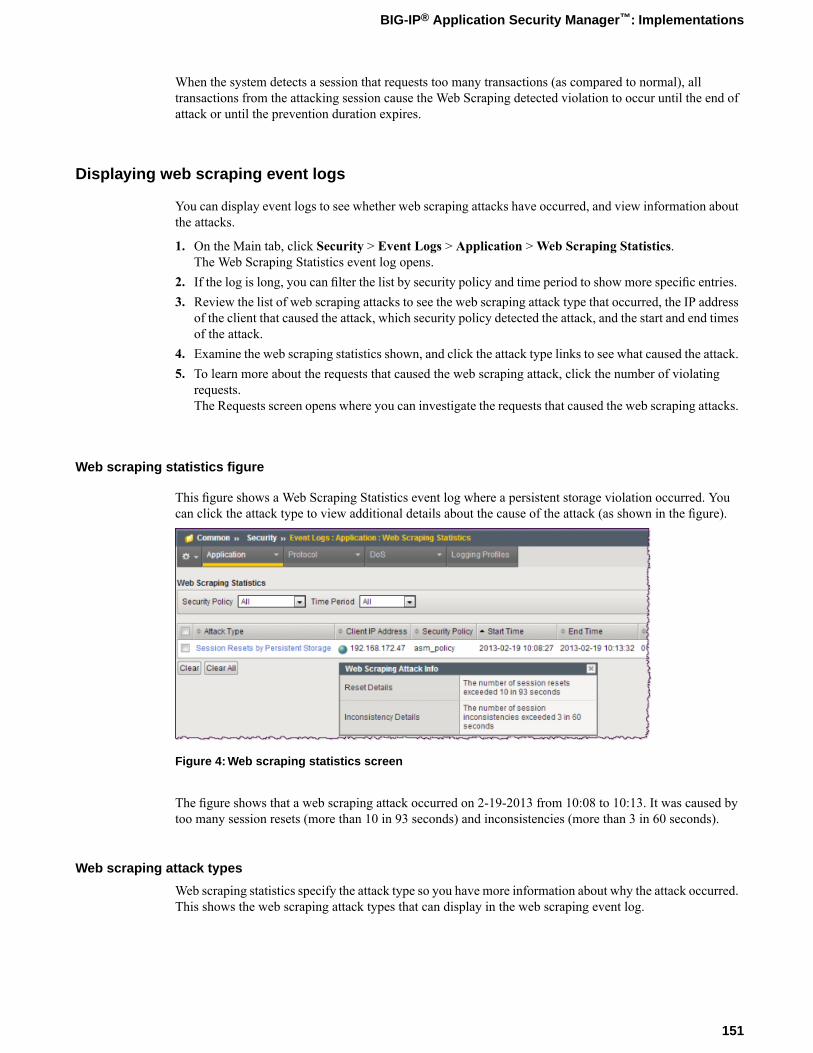
When the system detects a session that requests too many transactions (as compared to normal), alltransactions from the attacking session cause the Web Scraping detected violation to occur until the end ofattack or until the prevention duration expires.
Displaying web scraping event logs
You can display event logs to see whether web scraping attacks have occurred, and view information aboutthe attacks.
1. On the Main tab, click Security > Event Logs > Application >Web Scraping Statistics.The Web Scraping Statistics event log opens.
2. If the log is long, you can filter the list by security policy and time period to show more specific entries.3. Review the list of web scraping attacks to see the web scraping attack type that occurred, the IP address
of the client that caused the attack, which security policy detected the attack, and the start and end timesof the attack.
4. Examine the web scraping statistics shown, and click the attack type links to see what caused the attack.5. To learn more about the requests that caused the web scraping attack, click the number of violating
requests.The Requests screen opens where you can investigate the requests that caused the web scraping attacks.
Web scraping statistics figure
This figure shows a Web Scraping Statistics event log where a persistent storage violation occurred. Youcan click the attack type to view additional details about the cause of the attack (as shown in the figure).
Figure 4: Web scraping statistics screen
The figure shows that a web scraping attack occurred on 2-19-2013 from 10:08 to 10:13. It was caused bytoo many session resets (more than 10 in 93 seconds) and inconsistencies (more than 3 in 60 seconds).
Web scraping attack types
Web scraping statistics specify the attack type so you have more information about why the attack occurred.This shows the web scraping attack types that can display in the web scraping event log.
151
BIG-IP® Application Security Manager™: Implementations
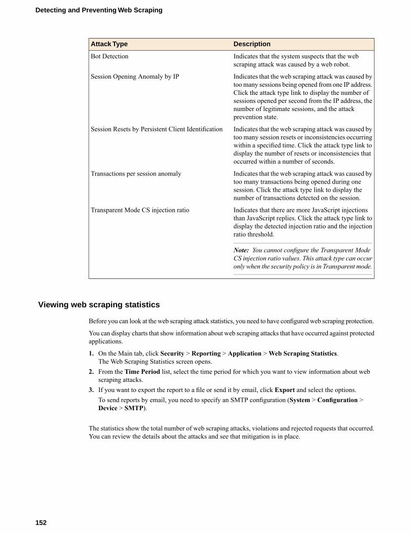
DescriptionAttack Type
Indicates that the system suspects that the webscraping attack was caused by a web robot.
Bot Detection
Indicates that the web scraping attack was caused bytoomany sessions being opened from one IP address.
Session Opening Anomaly by IP
Click the attack type link to display the number ofsessions opened per second from the IP address, thenumber of legitimate sessions, and the attackprevention state.
Indicates that the web scraping attack was caused bytoo many session resets or inconsistencies occurring
Session Resets by Persistent Client Identification
within a specified time. Click the attack type link todisplay the number of resets or inconsistencies thatoccurred within a number of seconds.
Indicates that the web scraping attack was caused bytoo many transactions being opened during one
Transactions per session anomaly
session. Click the attack type link to display thenumber of transactions detected on the session.
Indicates that there are more JavaScript injectionsthan JavaScript replies. Click the attack type link to
Transparent Mode CS injection ratio
display the detected injection ratio and the injectionratio threshold.
Note: You cannot configure the Transparent ModeCS injection ratio values. This attack type can occuronly when the security policy is in Transparent mode.
Viewing web scraping statistics
Before you can look at the web scraping attack statistics, you need to have configuredweb scraping protection.
You can display charts that show information about web scraping attacks that have occurred against protectedapplications.
1. On the Main tab, click Security > Reporting > Application >Web Scraping Statistics.The Web Scraping Statistics screen opens.
2. From the Time Period list, select the time period for which you want to view information about webscraping attacks.
3. If you want to export the report to a file or send it by email, click Export and select the options.To send reports by email, you need to specify an SMTP configuration (System > Configuration >Device > SMTP).
The statistics show the total number of web scraping attacks, violations and rejected requests that occurred.You can review the details about the attacks and see that mitigation is in place.
152
Detecting and Preventing Web Scraping
Implementation Result
When you have completed the steps in this implementation, you have configured the Application SecurityManager™ to protect against web scraping. Depending on your configuration, the system detects web scrapingattacks based on bot detection, session opening violations, or session transaction violations.
After traffic is flowing to the system, you can check whether web scraping attacks are being logged orprevented, and investigate them by viewing web scraping event logs and statistics.
If you chose alarm and block for the web scraping configuration and the security policy is in the blockingoperation mode, the system drops requests that cause the Web scraping detected violation. If you chosealarm only (or the policy is in the transparent mode), web scraping attacks are logged only but not blocked.
153
BIG-IP® Application Security Manager™: Implementations


Chapter
23Masking Credit Card Numbers in Logs
• Overview: Masking credit card numbers inlogs
Overview: Masking credit card numbers in logs
Application Security Manager™ (ASM) can mask credit card numbers in request logs. By default, whenyou create a security policy, the option to mask credit card numbers is enabled.Wherever credit card numbersappear in logs and violation details, they will be replaced by asterisks.
Keeping the Mask Credit Card Numbers in Request Log option enabled is required for PCI compliance.You must use this option in addition to Data Guard and masking sensitive parameters to comply with theProtect Stored Cardholder Data requirement. Data Guard masks sensitive information, such as credit cardnumbers and social security numbers, in responses.
Sensitive parameters mask sensitive information that is passed as parameters, such as credit card numbers.Making a parameter sensitive guarantees that its values are alwaysmasked in logs. Using sensitive parametersis good for form fields that are designated to contain sensitive data (like credit card numbers). But since auser can include credit card numbers in other places, enabling the Mask Credit Card Numbers in RequestLog option looks for them anywhere in the request and masks them, providing an additional layer of security.Masking credit card numbers in request logs
Masking credit card numbers in request logs
You can make sure that a security policy is set up to mask credit card numbers in logs and violations. Thisprotects sensitive information, specifically credit card numbers, more securely.
1. On the Main tab, click Security > Application Security > Security Policies.The Active Policies screen opens.
2. Click the name of the security policy you want to work on.The Properties screen opens.
3. Select theMask Credit Card Numbers in Request Log check box if it is not already enabled.4. Click Save.
The system saves the configuration settings.
The system now looks for occurrences of credit card numbers in request logs and violations and replacesthem with asterisks.
156
Masking Credit Card Numbers in Logs
Chapter
24Configuring HTTP Headers
• About mandatory headers• About header normalization• About default HTTP headers• Overview: Configuring HTTP headers• Implementation Result

About mandatory headers
A mandatory header is a header that must appear in a request for the request to be considered legal by thesystem. If a request does not contain the mandatory header and the Mandatory HTTP header is missingviolation is set to alarm or block, the system logs or blocks the request. This violation is not set to alarm orblock by default, so you have to set the blocking policy if you want to alarm or block requests that do notinclude a mandatory header.
You can usemandatory headers to make sure, for example, that requests are passing a proxy (which introducessuch a header) before they reach the Application Security Manager™.
You configure mandatory headers on the HTTP Headers screen.
About header normalization
Header normalization is a process whereby the Application Security Manager™ buffers the contents ofrequest headers to change them into a standard format that can be more easily checked for discrepancies.Normalizing deals with special characters (such as percent encoding), non-ASCII text, URL paths andparameters, Base64 encoded binary content, non-printable characters, HTML codes, and many other formatsthat may be used in headers that could potentially hide malicious code.
Not all headers need to be normalized. You should normalize referer headers, and custom headers containingbinary data, URLs, or other encoded information. But there is a performance trade-off when usingnormalization, so you should implement it only when needed.
You configure header normalization on the HTTP Headers screen when you select the option to checksignatures for the header.
About default HTTP headers
Application Security Manager™ (ASM) includes the default HTTP headers listed in the table.
DescriptionHeader Name
This wildcardHTTP header checks signatures againstall requests unless theymatch another HTTP header.
* (wildcard)
No normalization settings are selected by default,but you can edit them. Realize that enablingnormalization on the wildcard header may impactperformance. TheBase64Decoding andMandatorycheck boxes are unavailable for this header.
When requests have referer headers, they includeURLs. The system checks signatures against them,
referer
performs URL normalization, and validates the URLsyntax. Violations are issued if problems areencountered during normalization. The other settingsare not typically relevant for this header.
158
Configuring HTTP Headers
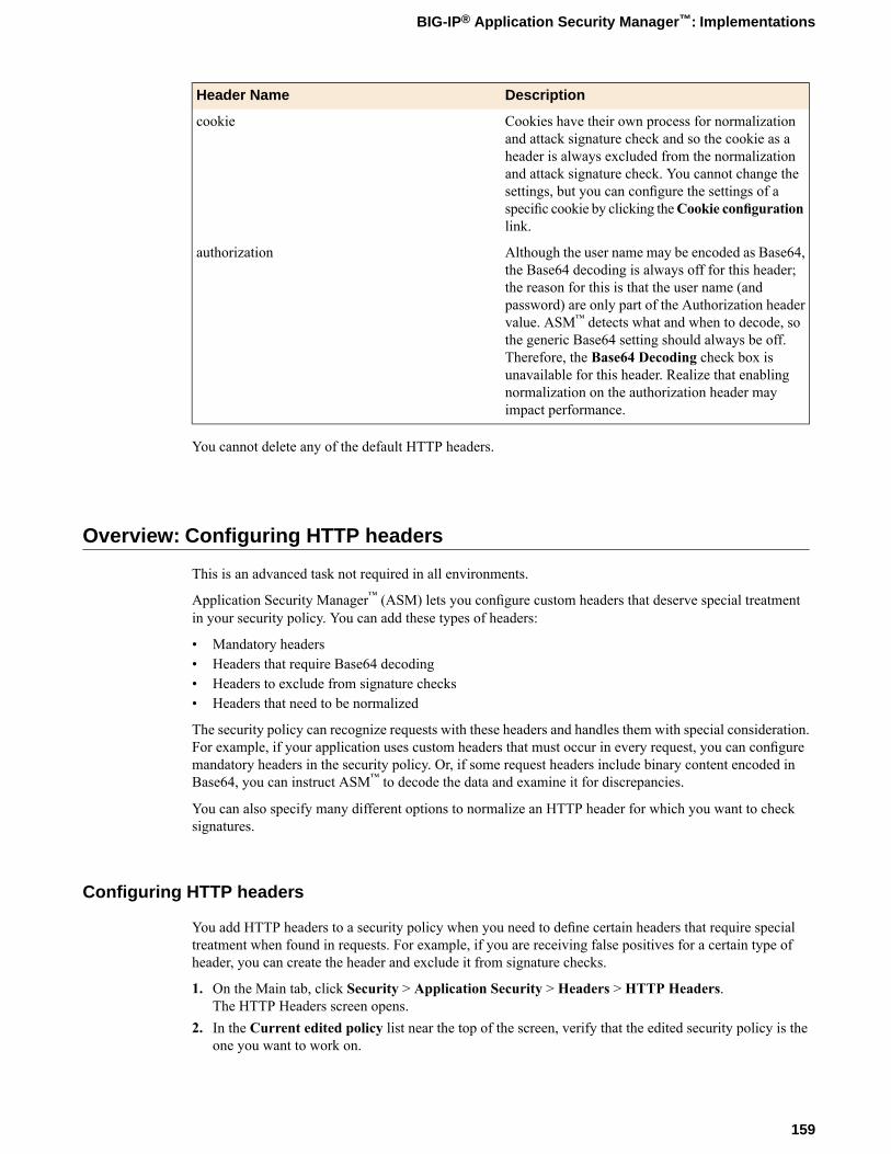
DescriptionHeader Name
Cookies have their own process for normalizationand attack signature check and so the cookie as a
cookie
header is always excluded from the normalizationand attack signature check. You cannot change thesettings, but you can configure the settings of aspecific cookie by clicking theCookie configurationlink.
Although the user name may be encoded as Base64,the Base64 decoding is always off for this header;
authorization
the reason for this is that the user name (andpassword) are only part of the Authorization headervalue. ASM™ detects what and when to decode, sothe generic Base64 setting should always be off.Therefore, the Base64 Decoding check box isunavailable for this header. Realize that enablingnormalization on the authorization header mayimpact performance.
You cannot delete any of the default HTTP headers.
Overview: Configuring HTTP headers
This is an advanced task not required in all environments.
Application Security Manager™ (ASM) lets you configure custom headers that deserve special treatmentin your security policy. You can add these types of headers:
• Mandatory headers• Headers that require Base64 decoding• Headers to exclude from signature checks• Headers that need to be normalized
The security policy can recognize requests with these headers and handles them with special consideration.For example, if your application uses custom headers that must occur in every request, you can configuremandatory headers in the security policy. Or, if some request headers include binary content encoded inBase64, you can instruct ASM™ to decode the data and examine it for discrepancies.
You can also specify many different options to normalize an HTTP header for which you want to checksignatures.
Configuring HTTP headers
You add HTTP headers to a security policy when you need to define certain headers that require specialtreatment when found in requests. For example, if you are receiving false positives for a certain type ofheader, you can create the header and exclude it from signature checks.
1. On the Main tab, click Security > Application Security > Headers > HTTP Headers.The HTTP Headers screen opens.
2. In the Current edited policy list near the top of the screen, verify that the edited security policy is theone you want to work on.
159
BIG-IP® Application Security Manager™: Implementations
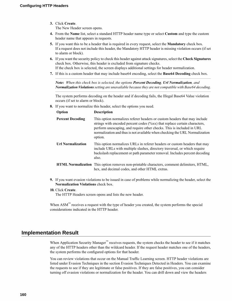
3. Click Create.The New Header screen opens.
4. From the Name list, select a standard HTTP header name type or select Custom and type the customheader name that appears in requests.
5. If you want this to be a header that is required in every request, select theMandatory check box.If a request does not include this header, the Mandatory HTTP header is missing violation occurs (if setto alarm or block).
6. If you want the security policy to check this header against attack signatures, select theCheck Signaturescheck box. Otherwise, this header is excluded from signature checks.If the check box is selected, the screen displays additional settings for header normalization.
7. If this is a custom header that may include base64 encoding, select the Base64 Decoding check box.
Note: When this check box is selected, the options Percent Decoding, Url Normalization, andNormalization Violations setting are unavailable because they are not compatible with Base64 decoding.
The system performs decoding on the header and if decoding fails, the Illegal Base64 Value violationoccurs (if set to alarm or block).
8. If you want to normalize this header, select the options you need.DescriptionOption
This option normalizes referer headers or custom headers that may includestrings with encoded percent codes (%xx) that replace certain characters,
Percent Decoding
perform unescaping, and require other checks. This is included in URLnormalization and thus is not available when checking the URLNormalizationoption.
This option normalizes URLs in referer headers or custom headers that mayinclude URLs with multiple slashes, directory traversal, or which require
Url Normalization
backslash replacement or path parameter removal. Includes percent decodingalso.
This option removes non-printable characters, comment delimiters, HTML,hex, and decimal codes, and other HTML extras.
HTMLNormalization
9. If you want evasion violations to be issued in case of problems while normalizing the header, select theNormalization Violations check box.
10. Click Create.The HTTP Headers screen opens and lists the new header.
When ASM™ receives a request with the type of header you created, the system performs the specialconsiderations indicated in the HTTP header.
Implementation Result
When Application Security Manager™ receives requests, the system checks the header to see if it matchesany of the HTTP headers other than the wildcard header. If the request header matches one of the headers,the system performs the configured options for that header.
You can review violations that occur on the Manual Traffic Learning screen. HTTP header violations arelisted under Evasion Techniques in the section Evasion Techniques Detected in Headers. You can examinethe requests to see if they are legitimate or false positives. If they are false positives, you can considerturning off evasion violations or normalization for the header. You can drill down and view the headers
160
Configuring HTTP Headers
causing violations. If a header violation is a false positive, you can also disable normalization from theEvasion Techniques Detected in Headers screen.
If signature violations occur in the header, the system suggests disabling the signature that cause the violation,or disabling the signature check for that header. If a header declared mandatory is missing, the systemsuggests disabling the violation or making the missing header non-mandatory.
If the Base64 violation occurs in the header, the system suggests disabling the violation or disabling theBase64 decoding for that header.
161
BIG-IP® Application Security Manager™: Implementations

Chapter
25Adding Cookies
• About cookies• About pure wildcard cookies• About cookies and learning• Overview: Adding cookies
About cookies
Many web-based applications use cookies to help users navigate the web site efficiently and perform certainfunctions. For example, web servers may use cookies to authenticate users logging in to secure applications,or an application can use cookies to store user preferences. Whether using automatic policy building ormanually creating a security policy, you may want to add cookies that the web application uses.
You may want a security policy to ignore certain known and recognized cookie headers that are includedin HTTP requests. For example, if cookies can change on the client side legitimately, you can create allowedcookies.
You may also want a security policy to prevent changes to specific cookies, such as session-related cookiesthat are set by the application. If so, you can create enforced cookies. The cookie in the request must not bemodified, or it generates the Modified Domain Cookie violation.
In addition, some PHP applications treat cookies as parameters and use the value of the cookie as input tothe application. For that reason, you can have the system check attack signatures on the cookie (as you canfor parameters). You can apply attack signatures only to allowed cookies, because enforced cookies are setby the server, and therefore, are considered to be secure.
Both allowed and enforced cookies can be put in staging when they are created so that you can make surethat they do not cause false positives during the staging period.
If you are using automatic policy building, the security policy adds cookies automatically. If manuallybuilding a security policy, the manual traffic learning screens suggest cookies to add.
About pure wildcard cookies
When you create a security policy, it includes a pure wildcard (*) and it is created as an allowed cookie inthe Allowed Cookies list. You cannot delete the pure wildcard from the security policy but you can changeits type from allowed to enforced. The allowed cookie wildcard allows all cookies, and you can specifywhich cookies the users cannot change in the enforced cookies list .This is considered a negative securitymodel, because you allow all cookies except the ones you specify.
However, new cookies are added to the security policy (or not) based on the Learn Explicit Entities valueof the matched wildcard. The value can be Never (do not add cookies) or Selective (add cookies that matchthe wildcard). The default value differs depending on the deployment scenario you use to create the policy.
The following deployments create pure wildcard cookies using the value Never, thus they do not add (orsuggest to add) explicit cookies to the security policy:
• All templates (including Rapid Deployment policy)• Automatic policy building with Fundamental policy type• Vulnerability assessment
All other deployment scenarios create the pure wildcard cookie with Learn Explicit Entities set to Selective.So it adds (if building the policy automatically) or suggests to add (if building the policy manually) explicitcookies encountered in the traffic to the security policy.
In Selective mode, the system learns cookies that violate the settings of the wildcard. In particular, cookiesthat do not change are learned as enforced cookies. Most cookies are added to the security policy as allowedcookies, and are checked for the configured signature set. These are captured by the * pure wildcard. Theexceptions are the enforced cookies and cookies that need to be exempted from some of the signature checks.These are whitelisted.
164
Adding Cookies
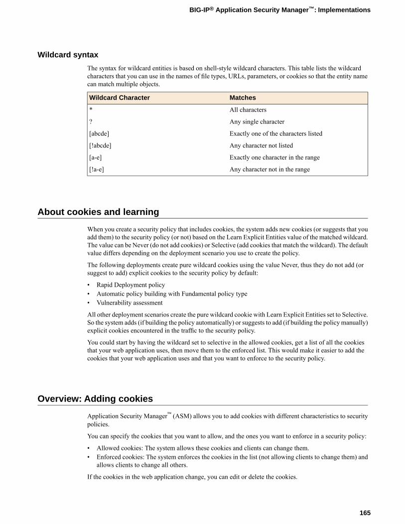
Wildcard syntax
The syntax for wildcard entities is based on shell-style wildcard characters. This table lists the wildcardcharacters that you can use in the names of file types, URLs, parameters, or cookies so that the entity namecan match multiple objects.
MatchesWildcard Character
All characters*
Any single character?
Exactly one of the characters listed[abcde]
Any character not listed[!abcde]
Exactly one character in the range[a-e]
Any character not in the range[!a-e]
About cookies and learning
When you create a security policy that includes cookies, the system adds new cookies (or suggests that youadd them) to the security policy (or not) based on the Learn Explicit Entities value of the matched wildcard.The value can be Never (do not add cookies) or Selective (add cookies that match the wildcard). The defaultvalue differs depending on the deployment scenario you use to create the policy.
The following deployments create pure wildcard cookies using the value Never, thus they do not add (orsuggest to add) explicit cookies to the security policy by default:
• Rapid Deployment policy• Automatic policy building with Fundamental policy type• Vulnerability assessment
All other deployment scenarios create the pure wildcard cookie with Learn Explicit Entities set to Selective.So the system adds (if building the policy automatically) or suggests to add (if building the policy manually)explicit cookies encountered in the traffic to the security policy.
You could start by having the wildcard set to selective in the allowed cookies, get a list of all the cookiesthat your web application uses, then move them to the enforced list. This would make it easier to add thecookies that your web application uses and that you want to enforce to the security policy.
Overview: Adding cookies
Application Security Manager™ (ASM) allows you to add cookies with different characteristics to securitypolicies.
You can specify the cookies that you want to allow, and the ones you want to enforce in a security policy:
• Allowed cookies: The system allows these cookies and clients can change them.• Enforced cookies: The system enforces the cookies in the list (not allowing clients to change them) and
allows clients to change all others.
If the cookies in the web application change, you can edit or delete the cookies.
165
BIG-IP® Application Security Manager™: Implementations
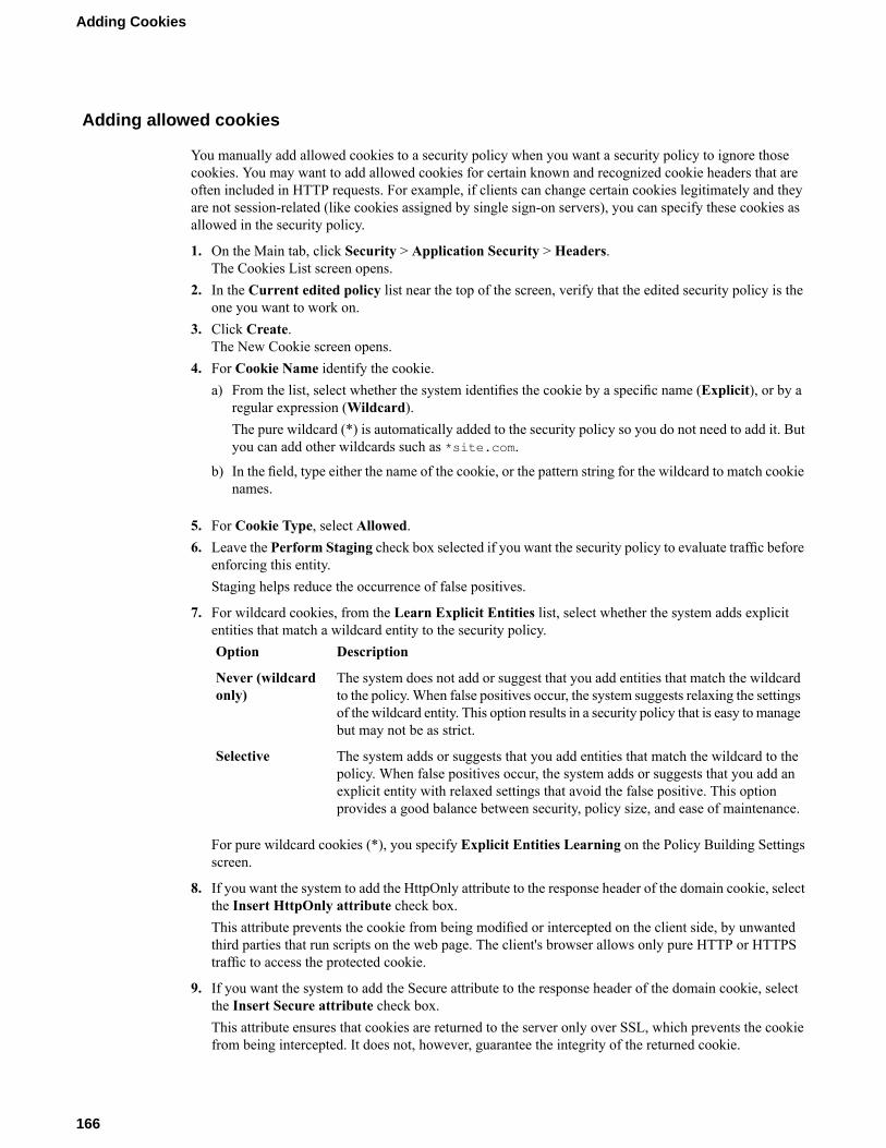
Adding allowed cookies
You manually add allowed cookies to a security policy when you want a security policy to ignore thosecookies. You may want to add allowed cookies for certain known and recognized cookie headers that areoften included in HTTP requests. For example, if clients can change certain cookies legitimately and theyare not session-related (like cookies assigned by single sign-on servers), you can specify these cookies asallowed in the security policy.
1. On the Main tab, click Security > Application Security > Headers.The Cookies List screen opens.
2. In the Current edited policy list near the top of the screen, verify that the edited security policy is theone you want to work on.
3. Click Create.The New Cookie screen opens.
4. For Cookie Name identify the cookie.a) From the list, select whether the system identifies the cookie by a specific name (Explicit), or by a
regular expression (Wildcard).The pure wildcard (*) is automatically added to the security policy so you do not need to add it. Butyou can add other wildcards such as *site.com.
b) In the field, type either the name of the cookie, or the pattern string for the wildcard to match cookienames.
5. For Cookie Type, select Allowed.6. Leave the Perform Staging check box selected if you want the security policy to evaluate traffic before
enforcing this entity.Staging helps reduce the occurrence of false positives.
7. For wildcard cookies, from the Learn Explicit Entities list, select whether the system adds explicitentities that match a wildcard entity to the security policy.
DescriptionOption
The system does not add or suggest that you add entities that match the wildcardto the policy. When false positives occur, the system suggests relaxing the settings
Never (wildcardonly)
of the wildcard entity. This option results in a security policy that is easy to managebut may not be as strict.
The system adds or suggests that you add entities that match the wildcard to thepolicy. When false positives occur, the system adds or suggests that you add an
Selective
explicit entity with relaxed settings that avoid the false positive. This optionprovides a good balance between security, policy size, and ease of maintenance.
For pure wildcard cookies (*), you specify Explicit Entities Learning on the Policy Building Settingsscreen.
8. If you want the system to add the HttpOnly attribute to the response header of the domain cookie, selectthe Insert HttpOnly attribute check box.This attribute prevents the cookie from being modified or intercepted on the client side, by unwantedthird parties that run scripts on the web page. The client's browser allows only pure HTTP or HTTPStraffic to access the protected cookie.
9. If you want the system to add the Secure attribute to the response header of the domain cookie, selectthe Insert Secure attribute check box.This attribute ensures that cookies are returned to the server only over SSL, which prevents the cookiefrom being intercepted. It does not, however, guarantee the integrity of the returned cookie.
166
Adding Cookies
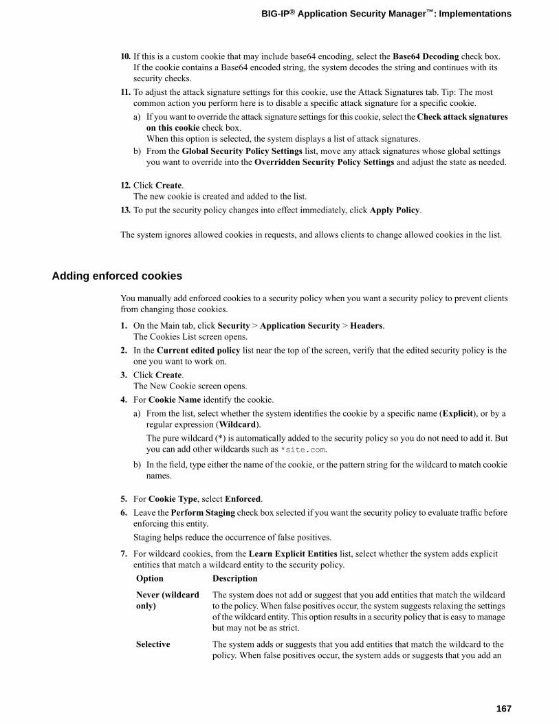
10. If this is a custom cookie that may include base64 encoding, select the Base64 Decoding check box.If the cookie contains a Base64 encoded string, the system decodes the string and continues with itssecurity checks.
11. To adjust the attack signature settings for this cookie, use the Attack Signatures tab. Tip: The mostcommon action you perform here is to disable a specific attack signature for a specific cookie.a) If you want to override the attack signature settings for this cookie, select theCheck attack signatures
on this cookie check box.When this option is selected, the system displays a list of attack signatures.
b) From the Global Security Policy Settings list, move any attack signatures whose global settingsyou want to override into the Overridden Security Policy Settings and adjust the state as needed.
12. Click Create.The new cookie is created and added to the list.
13. To put the security policy changes into effect immediately, click Apply Policy.
The system ignores allowed cookies in requests, and allows clients to change allowed cookies in the list.
Adding enforced cookies
You manually add enforced cookies to a security policy when you want a security policy to prevent clientsfrom changing those cookies.
1. On the Main tab, click Security > Application Security > Headers.The Cookies List screen opens.
2. In the Current edited policy list near the top of the screen, verify that the edited security policy is theone you want to work on.
3. Click Create.The New Cookie screen opens.
4. For Cookie Name identify the cookie.a) From the list, select whether the system identifies the cookie by a specific name (Explicit), or by a
regular expression (Wildcard).The pure wildcard (*) is automatically added to the security policy so you do not need to add it. Butyou can add other wildcards such as *site.com.
b) In the field, type either the name of the cookie, or the pattern string for the wildcard to match cookienames.
5. For Cookie Type, select Enforced.6. Leave the Perform Staging check box selected if you want the security policy to evaluate traffic before
enforcing this entity.Staging helps reduce the occurrence of false positives.
7. For wildcard cookies, from the Learn Explicit Entities list, select whether the system adds explicitentities that match a wildcard entity to the security policy.
DescriptionOption
The system does not add or suggest that you add entities that match the wildcardto the policy. When false positives occur, the system suggests relaxing the settings
Never (wildcardonly)
of the wildcard entity. This option results in a security policy that is easy to managebut may not be as strict.
The system adds or suggests that you add entities that match the wildcard to thepolicy. When false positives occur, the system adds or suggests that you add an
Selective
167
BIG-IP® Application Security Manager™: Implementations
DescriptionOptionexplicit entity with relaxed settings that avoid the false positive. This optionprovides a good balance between security, policy size, and ease of maintenance.
For pure wildcard cookies (*), you specify Explicit Entities Learning on the Policy Building Settingsscreen.
8. If you want the system to add the HttpOnly attribute to the response header of the domain cookie, selectthe Insert HttpOnly attribute check box.This attribute prevents the cookie from being modified or intercepted on the client side, by unwantedthird parties that run scripts on the web page. The client's browser allows only pure HTTP or HTTPStraffic to access the protected cookie.
9. If you want the system to add the Secure attribute to the response header of the domain cookie, selectthe Insert Secure attribute check box.This attribute ensures that cookies are returned to the server only over SSL, which prevents the cookiefrom being intercepted. It does not, however, guarantee the integrity of the returned cookie.
10. Click Create.The new cookie is created and added to the list.
11. To put the security policy changes into effect immediately, click Apply Policy.
If a request contains a modified or unsigned enforced cookie header and the Modified domain cookie(s)violation is set to alarm or block, the system logs and/or blocks the request (when the system is in blockingmode). Note that the request is not blocked if the enforced cookie is in staging, or if the security policy isin transparent mode.
Changing the order in which wildcard cookies are enforced
If you create several wildcard cookies, the security policy adds each new one to the top of the wildcardcookies list. The cookie wildcards are enforced from the top of the list down. You can change the order inwhich a security policy enforces wildcard cookies.
1. On the Main tab, click Security > Application Security > Headers > Cookie Wildcards Order.The Cookie Wildcards Order screen opens.
2. In the Current edited policy list near the top of the screen, verify that the edited security policy is theone you want to work on.
3. Select either the Enforced Cookies or Allowed Cookies tab to locate the cookie you want to edit.4. In theWildcard Cookies list, adjust the order of the cookie wildcards by using the Up and Down buttons
putting the cookies you want to enforce first at the top of the list.5. Click Save to save the changes.6. To put the security policy changes into effect immediately, click Apply Policy.
The system enforces the cookie wildcards from the top down.
Editing cookies
You can edit cookies as required by changes in the web application that the security policy is protecting.
1. On the Main tab, click Security > Application Security > Headers.The Cookies List screen opens.
168
Adding Cookies
2. In the Current edited policy list near the top of the screen, verify that the edited security policy is theone you want to work on.
3. Select either the Enforced Cookies or Allowed Cookies tab to locate the cookie you want to edit.4. In the Cookie Name column, click the cookie name.
The Edit Cookie screen opens.5. In the Cookie Properties area, make the required changes to the cookie.6. Click Update to save the changes.7. To put the security policy changes into effect immediately, click Apply Policy.
Deleting cookies
You can delete cookies that are no longer needed in your security policy. If a cookie changes in yourapplication, you may want to delete the old cookie and let Application Security Manager™ add the newcookie (or suggest adding it).
1. On the Main tab, click Security > Application Security > Headers.The Cookies List screen opens.
2. In the Current edited policy list near the top of the screen, verify that the edited security policy is theone you want to work on.
3. Select either the Enforced Cookies or Allowed Cookies tab to locate the cookie you want to edit.4. In the Enforced Cookies or Allowed Cookies list, select the check box next to the cookie you want to
delete.5. Click Delete to delete the entity, and click OK when asked to confirm.6. To put the security policy changes into effect immediately, click Apply Policy.
Specifying when to add explicit cookies
You can specify the circumstances under which Application Security Manager™ adds, or suggests you add,explicit cookies to the security policy.
1. On the Main tab, click Security > Application Security > Policy Building > Settings.The Settings screen opens.
2. In the Current edited policy list near the top of the screen, verify that the edited security policy is theone you want to work on.
3. In the Explicit Entities Learning setting, for Cookies, select the option you want.DescriptionOption
The system does not add or suggest that you add cookies that match the wildcardto the policy. When false positives occur, the system suggests relaxing the settings
Never (wildcardonly)
of the wildcard entity. This option results in a security policy that is easy to managebut may not be as strict.
The system adds or suggests that you add cookies that match the wildcard to thepolicy. When false positives occur, the system adds or suggests that you add an
Selective
explicit entity with relaxed settings that avoid the false positive. This optionprovides a good balance between security, policy size, and ease of maintenance.
4. Click Save to save the changes.5. To put the security policy changes into effect immediately, click Apply Policy.
169
BIG-IP® Application Security Manager™: Implementations

Chapter
26Configuring Advanced Cookie Protection
• Overview: Configuring advanced cookieprotection
Overview: Configuring advanced cookie protection
Many of the Application Security Manager™ (ASM) security features store ASM™ cookies on clients aspart of the traffic security enforcement. Examples of security features that use cookies for validation arecookie enforcement, parameter enforcement, CSRF protection, login enforcement, session tracking, andanomaly detection. Cookie enforcement is also called domain cookies; cookies for the other features arecalled other ASM cookies.
The system applies a random security key unique to each deployment and uses it in conjunction with anencryption algorithm. The combination of the randomly generated key and the selected algorithms is calledthe security context. Normally, you do not have to change the cookie protection settings. However, in caseswhere you suspect a security breach has occurred, or if you want a different balance between speed andsecurity, you can reconfigure cookie protection.
By default, when you initially start the system, it automatically generates a security key and sets the cookiesecurity level to secure. You can change the encryption schema to provide faster cookie protection byreconfiguring cookie protection.
If you want to use the same security context on other systems, you can set up advanced cookie configurationsettings on one BIG-IP® system and export them. You can then import the settings on the other systems.You can configure all your systems to use the same cookie protection, or apply different settings to thesystems. However, if you have multiple ASM-enabled devices that share traffic (and are not synchronizedusing device groups), it is recommended that those systems should all use the same cookie protection settings.
If synchronizing multiple ASM systems using device groups, you can configure the settings you want touse for all systems on one and then synchronize the systems.
Reconfiguring cookie protection
Application Security Manager™ (ASM) automatically configures cookie protection. If you need to adjustcookie protection due to a security breach or because you want to change the current protection level, youcan reconfigure cookie protection.
Note: This is an advanced configuration task that is required only in special circumstances.
1. On the Main tab, click Security > Options > Application Security > Advanced Configuration >Cookie Protection.The Cookie Protection screen opens.
2. Review the data and time specified in the Latest Generation/Import Configuration Time setting tosee when cookie protection was last configured.
3. To review the details of the cookie protection, click View Algorithms Configuration.The screen shows the specific algorithms the system uses to protect domain and other ASM cookies.
4. If you decide that you want to change the cookie configuration, click Reconfigure Cookie Protection.The Reconfigure Cookie Protection screen opens.
5. For Grace Period Until signing with new Security Context, type the amount of time in minutes thatmust pass before the system begins signing ASM cookies with the new key and algorithm that you areconfiguring.The default value is 30 minutes. Initially when you start the system, this is the period the system waitsto apply the new security context for the new release.
6. For Grace Period To Accept Old Cookies, type the amount of time in minutes that must pass beforethe system stops accepting traffic with ASM cookies that use the old key and algorithm.
172
Configuring Advanced Cookie Protection
The default value is 2880 minutes (48 hours).
7. For Algorithm Selection, select the overall cookie security level to apply: Secure or Fast.
Tip: The Secure setting uses more system resources.
Changing this setting changes the Scramble and Mac algorithms used for cookie protection.8. If you want to review the actual algorithms used for the cookies, you can do this:
a) For the Cookie Protection Configuration setting, select Advanced.The screen shows additional settings.
b) Review the scramble and Mac algorithms used for the domain cookies and other ASM cookies, andadjust them if needed.If you use settings other than the defaults, the Algorithm Selection changes to Custom.
9. Click Reconfigure.The system regenerates a new security context but waits to start using it until it surpasses the graceperiod until signing value.
10. If you need to extend either of the grace periods, click Extend and type the number of minutes to addand click Save.
Importing cookie protection configuration
If you want to use the same cookie configuration settings on more than one Application Security Manager™
(ASM) system (especially systems that share traffic), you can export the settings from one system andimport them onto another one. This task explains how to import the settings.
1. On the Main tab, click Security > Options > Application Security > Advanced Configuration >Cookie Protection.The Cookie Protection screen opens.
2. Click Import.The Import Cookie Protection Configuration screen opens.
3. From the Import Method list, select Upload file and locate the previously exported configuration file.The exported file has a name such asASM_Cookie_Protection_Configuration_2013-08-15_08-22.txt.
4. To review the details of the cookie protection, click View Algorithms Configuration.The screen shows the specific algorithms the system uses to protect domain and other ASM cookies.
5. For Grace Period Until signing with new Security Context, type the amount of time in minutes thatmust pass before the system begins signing ASM cookies with the new key and algorithm that you areconfiguring.The default value is 30 minutes. Initially when you start the system, this is the period the system waitsto apply the new security context for the new release.
6. For Grace Period To Accept Old Cookies, type the amount of time in minutes that must pass beforethe system stops accepting traffic with ASM cookies that use the old key and algorithm.The default value is 2880 minutes (48 hours).
7. Click Import.The system imports the security context but waits to start using it until the grace period until signing isup.
8. If you need to extend either of the grace periods, click Extend and type the number of minutes to addand click Save.
173
BIG-IP® Application Security Manager™: Implementations
Exporting cookie protection configuration
If you want to use the same cookie configuration settings on more than one Application Security Manager™
system, you can export the settings from one system and import them onto another one. This task explainshow to export the settings to a file.
1. On the Main tab, click Security > Options > Application Security > Advanced Configuration >Cookie Protection.The Cookie Protection screen opens.
2. Click Export.The system exports the cookie protection configuration to a file with a name such asASM_Cookie_Protection_Configuration_2013-08-15_08-22.txt.
174
Configuring Advanced Cookie Protection
Chapter
27Enforcing Path Parameter Security
• Overview: Enforcing path parameter security
Overview: Enforcing path parameter security
Path parameters are parameters that are attached to path segments in the URI. You can configure ApplicationSecurity Manager™ (ASM) to enforce path parameters as needed in your organization. Path parameters canbe ignored, or treated as parameters, or as an integral part of URLs.
Although path parameters are not widely used, they could serve as covert back doors to potential attackseven for server applications that do not use path parameters. For example, an application could copy a URIwith path parameters containing attack signatures to the body of the response.
Path parameters can havemultiple parameters in the same path segment separated by semicolons. A semicolonalso separates the path segment from the parameters; for example, /path/name;param1;p2;p3. Eachparameter can optionally equal a value; for example, param=value;p2. If a path parameter has more thanone value, the values are separated by commas, such as param=val1,val2,val3.
Path parameters are extracted from requests, but not from responses.
Enforcing path parameter security
You can configure how a security policy handles path parameters that are attached to path segments inURIs. You can enforce different levels of security based on your needs.
1. On the Main tab, click Security > Application Security > Security Policies.The Active Policies screen opens.
2. Click the name of the security policy you want to work on.The Properties screen opens.
3. From the Configuration list, select Advanced.4. Scroll down to Handle Path Parameters, and select how you want to treat path parameters in URIs.
DescriptionOption
The system normalizes and enforces path parameters. For each path parameter,the system removes it from the URL as part of the normalization process, finds a
As Parameter
corresponding parameter in the security policy (first at the matching URL level,and if not found, then at the Global level), and enforces it according to its attributeslike any other parameter.
The system does not normalize or enforce path parameters, and treats them as anintegral part of the URL.
As URL
The system removes path parameters from URLs as part of the normalizationprocess, but does not enforce them.
Ignore
5. Click Save.6. In the editing context area, click Apply Policy to put the changes into effect.
Path parameters in URIs are handled as specified in the security policy properties.
176
Enforcing Path Parameter Security
Chapter
28Integrating ASM with Database Security Products
• Overview: Integrating ASM with databasesecurity products
• Implementation result
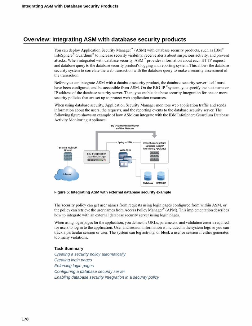
Overview: Integrating ASM with database security products
You can deploy Application Security Manager™ (ASM) with database security products, such as IBM®
InfoSphere® Guardium® to increase security visibility, receive alerts about suspicious activity, and preventattacks. When integrated with database security, ASM™ provides information about each HTTP requestand database query to the database security product's logging and reporting system. This allows the databasesecurity system to correlate the web transaction with the database query to make a security assessment ofthe transaction.
Before you can integrate ASM with a database security product, the database security server itself musthave been configured, and be accessible from ASM. On the BIG-IP ®system, you specify the host name orIP address of the database security server. Then, you enable database security integration for one or moresecurity policies that are set up to protect web application resources.
When using database security, Application Security Manager monitors web application traffic and sendsinformation about the users, the requests, and the reporting events to the database security server. Thefollowing figure shows an example of howASM can integrate with the IBM InfoSphere GuardiumDatabaseActivity Monitoring Appliance.
Figure 5: Integrating ASM with external database security example
The security policy can get user names from requests using login pages configured from within ASM, orthe policy can retrieve the user names fromAccess PolicyManager® (APM). This implementation describeshow to integrate with an external database security server using login pages.
When using login pages for the application, you define the URLs, parameters, and validation criteria requiredfor users to log in to the application. User and session information is included in the system logs so you cantrack a particular session or user. The system can log activity, or block a user or session if either generatestoo many violations.
Task SummaryCreating a security policy automaticallyCreating login pagesEnforcing login pagesConfiguring a database security serverEnabling database security integration in a security policy
178
Integrating ASM with Database Security Products
Creating a security policy automatically
Before you can create a security policy, you must perform the minimal system configuration tasks includingdefining a VLAN, a self IP address, and other tasks required according to the needs of your networkingenvironment.
Application Security Manager™ can automatically create a security policy that is tailored to secure yourweb application.
1. On the Main tab, click Security > Application Security > Security Policies.The Active Policies screen opens.
2. Click the Create button.The Deployment wizard opens to the Select Local Traffic Deployment Scenario screen.
3. For the Local Traffic Deployment Scenario setting, specify a virtual server to use for the securitypolicy.
• To secure an existing virtual server that has no security policy associated with it, select ExistingVirtual Server and click Next.
• To create a new virtual server and pool with basic configuration settings, selectNew Virtual Serverand click Next.
• To create an active but unused security policy, select Do not associate with Virtual Server andclick Next. No traffic will go through this security policy until you associate it with a virtual server.The Policy Builder cannot begin automatically creating a policy until traffic is going to ASM throughthe virtual server.
The virtual server represents the web application you want to protect.The Configure Local Traffic Settings screen opens.
4. Configure the new or existing virtual server, and click Next.
• If creating a new virtual server, specify the protocol, name, IP address and port, pool IP address, andport.
• If using an existing virtual server, it must have an HTTP profile and cannot be associated with alocal traffic policy.
• If you selectDo not associate with Virtual Server, you will have to manually associate the securitypolicy with a virtual server at a later time. On the policy properties screen, you need to specify aname for the security policy.
The name of the new or existing virtual server becomes the name of the security policy.The Select Deployment Scenario screen opens.
5. For Deployment Scenario, select Create a policy automatically and click Next.The Configure Security Policy Properties screen opens.
6. From the Application Language list, select the language encoding of the application, or select Autodetect and let the system detect the language.
Important: You cannot change this setting after you have created the security policy.
7. If the application is not case-sensitive, clear the Security Policy is case sensitive check box. Otherwise,leave it selected.
Important: You cannot change this setting after you have created the security policy.
8. If you do not want the security policy to distinguish between HTTP and HTTPS URLs, clear theDifferentiate between HTTP and HTTPS URLs check box. Otherwise, leave it selected.
179
BIG-IP® Application Security Manager™: Implementations
Important: You cannot change this setting after you have created the security policy.
9. Click Next.The Configure Attack Signatures screen opens.
10. To configure attack signatures, move the systems used by your web application from the AvailableSystems list into the Assigned Systems list.The system adds the attack signatures needed to protect the selected systems.
11. For the Signature Staging setting, verify that the default option Enabled is selected.
Note: Because the Real Traffic Policy Builder® begins building the security policy in Blocking mode,you can keep signature staging enabled to make sure that false positives do not occur.
New and updated attack signatures remain in staging for 7 days, and are not enforced (according to thelearn, alarm, and block flags) during that time.
12. Click Next.The Configure Automatic Policy Building screen opens.
13. For Policy Type, select an option to determine the security features to include in the policy.DescriptionOption
Creates a security policy enforcing HTTP protocol compliance, evasion techniques,explicit file types (including length checks), explicit parameters in selective mode
Fundamental
at the global level, attack signatures, the violation Request Length Exceeds DefinedBuffer Size, host names, header lengths, cookie lengths, and the violation Failedto Convert Character.
Creates a security policy with all the elements of the Fundamental policy type;also checks for explicit URLs in selective mode plus meta characters, Explicit
Enhanced
parameter length checks in selective mode at the global level, methods, explicitcookies, and content profiles.
Creates a security policy with all the elements of the Enhanced policy type; alsochecks for explicit URLs and meta characters, explicit parameters and lengths atthe URL level, parameter meta characters, and dynamic parameters.
Comprehensive
A bulleted list on the screen describes which security features are included in each type.
14. For Rules, move the slider to set the Policy Builder learning speed.DescriptionOption
Use if your application supports a small number of requests from a small number ofsessions; for example, useful for web sites with less traffic. However, choosing thisoption may present a greater chance of adding false entities to the security policy.
Fast
Use if your application supports a medium number of requests, or if you are not sureabout the amount of traffic on the application web site. This is the default setting.
Medium
Use if your application supports a large number of requests from many sessions; forexample, useful for web sites with lots of traffic. This option creates the most accuratesecurity policy, but takes Policy Builder longer to collect the statistics.
Slow
Based on the option you select, the system sets greater or lesser values for the number of different usersessions, different IP addresses, and length of time before it adds to the security policy and enforces theelements.
15. For Trusted IP Addresses, select which IP addresses to consider safe:
180
Integrating ASM with Database Security Products
DescriptionOption
Specifies that the policy trusts all IP addresses. For example, if the traffic is in acorporate lab or preproduction environment where all of the traffic is trusted, thepolicy is created faster when you select this option.
All
Specifies networks to consider safe. Fill in the IP Address and Netmask fields,then click Add. This option is typically used in a production environment where
Address List
traffic could come from untrusted sources. The IP Address can be either an IPv4or an IPv6 address.
If you leave the trusted IP address list empty, the system treats all traffic as untrusted. In general, it takesmore untrusted traffic, from different IP addresses, over a longer period of time to build a security policy.
16. If you want the security policy to automatically detect JSON and XML protocols, select the JSON/XMLpayload detection check box.If requests contain legitimate XML or JSON data, the Policy Builder creates content profiles in thesecurity policy according to the data it detects.
17. If you want to display a response page when an AJAX request does not adhere to the security policy,select the AJAX blocking response behavior check box.
18. Click Next.The Security Policy Configuration Summary opens where you can review the settings to be sure theyare correct.
19. Click Finish to create the security policy.The Automatic Policy Building Status screen opens where you can view the current state of the securitypolicy.
ASM™ creates the virtual server with an HTTP profile, and on the Security tab, Application SecurityPolicy is enabled and associated with the security policy you created. A local traffic policy is also createdand by default sends all traffic for the virtual server to ASM. The Policy Builder automatically beginsexamining the traffic to the web application and building the security policy (unless you did not associatea virtual server). The system sets the enforcement mode of the security policy to Blocking, but it does notblock requests until the Policy Builder processes sufficient traffic, adds elements to the security policy, andenforces the elements.
Tip: This is a good point at which to test that you can access the application being protected by the securitypolicy and check that traffic is being processed by the BIG-IP® system.
Creating login pages
In your security policy, you can create a login page to specify a login URL that presents a site that usersmust pass through to gain access to the web application. The login URL commonly leads to the login pageof the web application.
1. On the Main tab, click Security > Application Security > Sessions and Logins.The Login Pages List screen opens.
2. In the Current edited policy list near the top of the screen, verify that the edited security policy is theone you want to work on.
3. Click Create.The New Login Page screen opens.
4. For the Login URL setting, specify a URL that users must pass through to get to the application.a) From the list, select the type of URL: Explicit orWildcard.
181
BIG-IP® Application Security Manager™: Implementations
b) Select either HTTP or HTTPS based on the type of traffic the web application accepts.c) Type an explicit URL or wildcard expression in the box.
When you click in the field, the system lists URLs that it has seen, and you can select a URL fromthe list. Or, you can type explicit URLs in the format /login, and wildcard URLs without the slash,such as *.php.
5. From the Authentication Type list, select the method the web server uses to authenticate the loginURL's credentials with a web user.
DescriptionOption
The web application uses a form to collect and authenticate user credentials.If using this option, you also need to type the user name and passwordparameters written in the code of the HTML form.
HTML Form
The user name and password are transmitted in Base64 and stored on theserver in plain text.
HTTP BasicAuthentication
The web server performs the authentication; user names and passwordsare not transmitted over the network, nor are they stored in plain text.
HTTP DigestAuthentication
Microsoft® LANManager authentication (also called Integrated WindowsAuthentication) does not transmit credentials in plain text, but requires acontinuous TCP connection between the server and client.
NTLM
6. In the Access Validation area, define at least one validation criteria for the login page response.If you define more than one validation criteria, the response must meet all the criteria before the systemallows the user to access the application.
Note: See the online help for definitions of the criteria.
7. Click Create to add the login page to the security policy.The new login page is added to the login pages list.
8. Add as many login pages as needed for your web application.9. In the editing context area, click Apply Policy to put the changes into effect.
The security policy now has one or more login pages associated with it.
You can now configure how the login pages are enforced, including the authentication URLs, logout URLs,and whether or not the login pages have time limits.
Enforcing login pages
Login enforcement settings prevent forceful browsing attacks where attackers gain access to restricted partsof the web application by supplying a URL directly. You can use login enforcement to force users to passthrough one URL (known as the login URL) before being allowed to display a different URL (known asthe target URL) where they can access restricted pages and resources. Login enforcement settings specifyhow the security policy enforces login pages including the expiration time, authenticated URLs, and logoutURLs. You can also use authenticated URLs to enforce idle time-outs on applications that are missing thisfunctionality.
1. On theMain tab, click Security >Application Security > Sessions and Logins >Login Enforcement.The Login Enforcement screen opens.
2. If you want the login URL to be valid for a limited time, set Expiration Time to Enabled, and type avalue, in seconds.
182
Integrating ASM with Database Security Products
3. Specify the target URLs that users can access only by way of the login URLs:a) For the Authenticated URLs setting, type the target URL name in the format /private.php
(wildcards are allowed).b) Click Add to add the URL to the list of authenticated URLs.c) Add as many authenticated URLs as needed.
4. Optionally, specify the URLs used to log out of the web application:a) For the Logout URLs setting, type the URL in the format /logout.html (explicit URLs only).b) Click Add.c) Add as many logout URLs as needed.
5. Click Save.The system saves the configuration settings.
If you specify authenticated URLs and a user tries to bypass them, the system now issues the Login URLbypassed violation. If a user session is idle and exceeds the expiration time, the system now issues theLogin URL expired violation, and the user can no longer reach the authenticated URLs. For both loginviolations, if the enforcement mode is blocking, the system now sends the Login Page Response to the client(see Application Security > Blocking > Response Pages).
Configuring a database security server
To integrate Application Security Manager™ (ASM) with a third-party database security product, you needto configure the database security server on ASM™. You can configure one database security server persystem.
1. On the Main tab, click Security >Options > Application Security > Integrated Services > DatabaseSecurity.The Database Security screen opens.
2. Specify the database security server by typing either its Server Host Name or its Server IP Address.Only one of the two fields is required.
Note: If using SSL to establish a secured session between the BIG-IP ®system and the database securityserver, type the IP address of a virtual server configured for the secure connection. The virtual serveruses any open IP address for the destination, the IBM Guardium port (16016, by default) for the serviceport, serverssl or a customized profile for the SSL Profile (Server) setting, and specifies a defaultpool (containing one member, the database security server, using its IP address and service port,typically, 16016).
3. For Server Port Number, type the port number of the database server.The default value is 16016, the port used by IBM® InfoSphere® Guardium.®
4. If you want the system to wait for an ACK response from the database security server before sendingthe request to the application server, from the Request Hold Timeout list, select Enabled and type thenumber of milliseconds to wait for the response.The default value is 5 milliseconds.When this setting is enabled, the system forwards the request to the application server as soon as thedatabase security server sends an ACK, or when the timeout has passed. If you leave this setting disabled,the system forwards the request to the application server immediately.
5. Click Save.The system saves the configuration settings.
183
BIG-IP® Application Security Manager™: Implementations
The Application Security Manager is now configured to connect to the database security server.
For ASM to forward request data to the database security server, you next need to enable database securityintegration in one or more security policies.
Enabling database security integration in a security policy
Before you can enable database security integration, you need to have created a security policy to protectyour web application. For the policy to retrieve the user names of those making requests, you need to createlogin pages in Application Security Manager™ (ASM).
You enable database security integration in a security policy so that Application Security Manager (ASM™)forwards request information to a third-party database server.
1. On the Main tab, click Security > Application Security > Integrated Services > Database Security.The Database Security screen opens.
2. In the Current edited policy list near the top of the screen, verify that the edited security policy is theone you want to work on.
3. Select the Database Security Integration check box.4. For User Source, select Use Login Pages to have the system use an ASM login page to determine the
user source.If there is no login page configured in the security policy, click the login pages link to open a popupscreen where you can add one.
5. Click Save.The system saves the configuration settings.
The Application Security Manager connects to the database security server and can forward request dataabout traffic to it.
Implementation result
You have set up a BIG-IP® system to use Application Security Manager™ (ASM) to secure applicationtraffic and use login pages to check user credentials.
Client traffic is routed to the virtual server for the web application. ASM™ analyzes the request and checksfor security violations. ASM also verifies user credentials on the login page and sends the database securityserver a request notification. When ASM receives an acknowledgment from the database security server orthe request hold timeout is over, ASM forwards traffic that meets the security policy requirements to theapplication.
The database security server includes the application and user information provided by ASM, so it can beviewed in logs and reports on that system. The database security server can perform a more in-depth securityassessment of the web request.
If you want to review reports and event logs that associate the user name with the session information onthe BIG-IP system, you can set up session tracking (by enabling session awareness).When session awarenessis enabled, you can see the user names on the Event Logs: Application: Requests screen in the GeneralDetails section of specific requests. In addition, the Reporting: Application: Charts screen displays the userswho sent the illegal requests.
184
Integrating ASM with Database Security Products
Chapter
29Integrating ASM and APM with Database Security Products
• Overview: Integrating ASM and APM withdatabase security products
• Prerequisites for integrating ASM and APMwith database security
• Implementation result
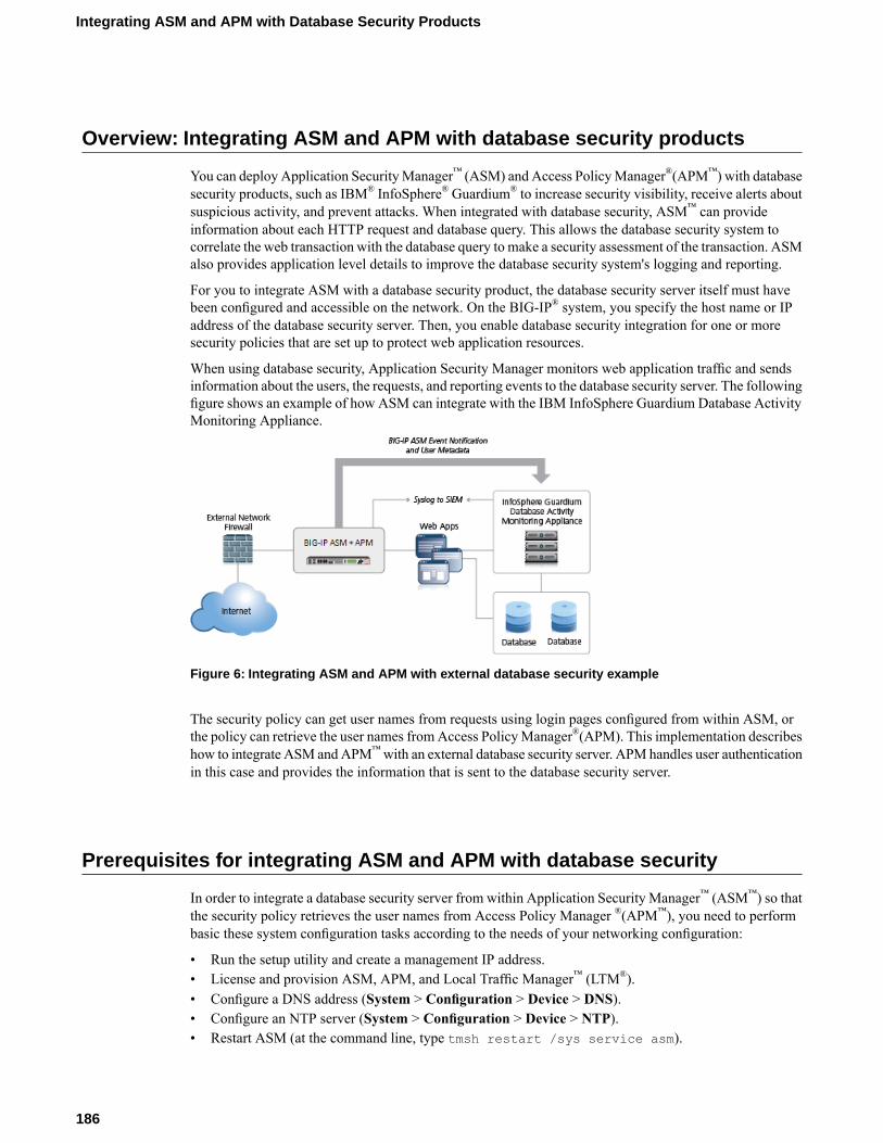
Overview: Integrating ASM and APM with database security products
You can deploy Application SecurityManager™ (ASM) and Access PolicyManager®(APM™) with databasesecurity products, such as IBM® InfoSphere® Guardium® to increase security visibility, receive alerts aboutsuspicious activity, and prevent attacks. When integrated with database security, ASM™ can provideinformation about each HTTP request and database query. This allows the database security system tocorrelate the web transaction with the database query to make a security assessment of the transaction. ASMalso provides application level details to improve the database security system's logging and reporting.
For you to integrate ASM with a database security product, the database security server itself must havebeen configured and accessible on the network. On the BIG-IP® system, you specify the host name or IPaddress of the database security server. Then, you enable database security integration for one or moresecurity policies that are set up to protect web application resources.
When using database security, Application Security Manager monitors web application traffic and sendsinformation about the users, the requests, and reporting events to the database security server. The followingfigure shows an example of how ASM can integrate with the IBM InfoSphere Guardium Database ActivityMonitoring Appliance.
Figure 6: Integrating ASM and APM with external database security example
The security policy can get user names from requests using login pages configured from within ASM, orthe policy can retrieve the user names fromAccess PolicyManager®(APM). This implementation describeshow to integrate ASM andAPM™with an external database security server. APM handles user authenticationin this case and provides the information that is sent to the database security server.
Prerequisites for integrating ASM and APM with database security
In order to integrate a database security server from within Application Security Manager™ (ASM™) so thatthe security policy retrieves the user names from Access Policy Manager ®(APM™), you need to performbasic these system configuration tasks according to the needs of your networking configuration:
• Run the setup utility and create a management IP address.• License and provision ASM, APM, and Local Traffic Manager™ (LTM®).• Configure a DNS address (System > Configuration > Device > DNS).• Configure an NTP server (System > Configuration > Device > NTP).• Restart ASM (at the command line, type tmsh restart /sys service asm).
186
Integrating ASM and APM with Database Security Products

Task SummaryCreating a VLANCreating a self IP address for a VLANCreating a local traffic pool for application securityCreating a virtual server to manage HTTPS trafficCreating a security policy automaticallyCreating an access profileConfiguring an access policyAdding the access profile to the virtual serverConfiguring a database security serverEnabling database security integration with ASM and APM
Creating a VLAN
VLANs represent a collection of hosts that can share network resources, regardless of their physical locationon the network. You create a VLAN to associate physical interfaces with that VLAN.
1. On the Main tab, click Network > VLANs.The VLAN List screen opens.
2. Click Create.The New VLAN screen opens.
3. In the Name field, type a unique name for the VLAN.4. For the Interfaces setting, click an interface number from the Available list, and use the Move button
to add the selected interface to the Untagged list. Repeat this step as necessary.5. Click Finished.
The screen refreshes, and displays the new VLAN in the list.
Creating a self IP address for a VLAN
Ensure that you have at least one VLAN configured before you create a self IP address.
Self IP addresses enable the BIG-IP® system, and other devices on the network, to route application trafficthrough the associated VLAN.
1. On the Main tab, click Network > Self IPs.The Self IPs screen opens.
2. Click Create.The New Self IP screen opens.
3. In the Name field, type a unique name for the self IP.4. In the IP Address field, type an IPv4 or IPv6 address.
This IP address should represent the address space of the VLAN that you specify with theVLAN/Tunnelsetting.
5. In the Netmask field, type the network mask for the specified IP address.6. From the VLAN/Tunnel list, select the VLAN to associate with this self IP address.
• On the internal network, select the VLAN that is associated with an internal interface or trunk.• On the external network, select the VLAN that is associated with an external interface or trunk.
7. Use the default values for all remaining settings.
187
BIG-IP® Application Security Manager™: Implementations
8. Click Finished.The screen refreshes, and displays the new self IP address in the list.
The BIG-IP system can now send and receive TCP/IP traffic through the specified VLAN.
Creating a local traffic pool for application security
You can use a local traffic pool with Application Security Manager™ system to forward traffic to theappropriate resources.
Note: You can optionally create a pool as part of creating a security policy using the Deployment wizard.
1. On the Main tab, click Local Traffic > Pools.The Pool List screen opens.
2. Click Create.The New Pool screen opens.
3. In the Name field, type a unique name for the pool.4. In the Resources area, for the New Members setting, add to the pool the application servers that host
the web application:a) Type an IP address in the Address field.b) In the Service Port field, type a port number (for example, type 80 for the HTTP service), or select
a service name from the list.c) Click Add.
5. Click Finished.
The BIG-IP® system configuration now includes a local traffic pool containing the resources that you wantto protect using Application Security Manager™.
Creating a virtual server to manage HTTPS traffic
You can create a virtual server to manage HTTPS traffic.
1. On the Main tab, click Local Traffic > Virtual Servers.The Virtual Server List screen opens.
2. Click the Create button.The New Virtual Server screen opens.
3. In the Name field, type a unique name for the virtual server.4. For the Destination setting, select Host and in the Address field, type the IP address for the virtual
server.5. In the Service Port field, type 443 or select HTTPS from the list.6. From the Configuration list, select Advanced.7. From the HTTP Profile list, select http.8. For the SSL Profile (Client) setting, from theAvailable list, select clientssl, and using theMove button,
move the name to the Selected list.9. (Optional) From the SSL Profile (Server) list, select serverssl.
188
Integrating ASM and APM with Database Security Products
Note: This setting ensures that there is an SSL connection between the HTTP virtual server and theexternal HTTPS server.
10. From the Source Address Translation list, select Auto Map.11. From the Default Pool list, select the pool that is configured for application security.12. Click Finished.
The HTTPS virtual server appears in the Virtual Server List screen.
Creating a security policy automatically
Before you can create a security policy, you must perform the minimal system configuration tasks includingdefining a VLAN, a self IP address, and other tasks required according to the needs of your networkingenvironment.
Application Security Manager™ can automatically create a security policy that is tailored to secure yourweb application.
1. On the Main tab, click Security > Application Security > Security Policies.The Active Policies screen opens.
2. Click the Create button.The Deployment wizard opens to the Select Local Traffic Deployment Scenario screen.
3. For the Local Traffic Deployment Scenario setting, specify a virtual server to use for the securitypolicy.
• To secure an existing virtual server that has no security policy associated with it, select ExistingVirtual Server and click Next.
• To create a new virtual server and pool with basic configuration settings, selectNew Virtual Serverand click Next.
• To create an active but unused security policy, select Do not associate with Virtual Server andclick Next. No traffic will go through this security policy until you associate it with a virtual server.The Policy Builder cannot begin automatically creating a policy until traffic is going to ASM throughthe virtual server.
The virtual server represents the web application you want to protect.The Configure Local Traffic Settings screen opens.
4. Configure the new or existing virtual server, and click Next.
• If creating a new virtual server, specify the protocol, name, IP address and port, pool IP address, andport.
• If using an existing virtual server, it must have an HTTP profile and cannot be associated with alocal traffic policy.
• If you selectDo not associate with Virtual Server, you will have to manually associate the securitypolicy with a virtual server at a later time. On the policy properties screen, you need to specify aname for the security policy.
The name of the new or existing virtual server becomes the name of the security policy.The Select Deployment Scenario screen opens.
5. For Deployment Scenario, select Create a policy automatically and click Next.The Configure Security Policy Properties screen opens.
6. From the Application Language list, select the language encoding of the application, or select Autodetect and let the system detect the language.
189
BIG-IP® Application Security Manager™: Implementations
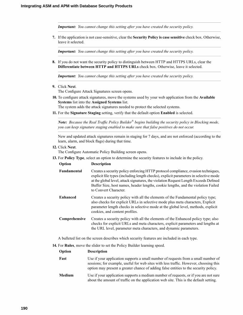
Important: You cannot change this setting after you have created the security policy.
7. If the application is not case-sensitive, clear the Security Policy is case sensitive check box. Otherwise,leave it selected.
Important: You cannot change this setting after you have created the security policy.
8. If you do not want the security policy to distinguish between HTTP and HTTPS URLs, clear theDifferentiate between HTTP and HTTPS URLs check box. Otherwise, leave it selected.
Important: You cannot change this setting after you have created the security policy.
9. Click Next.The Configure Attack Signatures screen opens.
10. To configure attack signatures, move the systems used by your web application from the AvailableSystems list into the Assigned Systems list.The system adds the attack signatures needed to protect the selected systems.
11. For the Signature Staging setting, verify that the default option Enabled is selected.
Note: Because the Real Traffic Policy Builder® begins building the security policy in Blocking mode,you can keep signature staging enabled to make sure that false positives do not occur.
New and updated attack signatures remain in staging for 7 days, and are not enforced (according to thelearn, alarm, and block flags) during that time.
12. Click Next.The Configure Automatic Policy Building screen opens.
13. For Policy Type, select an option to determine the security features to include in the policy.DescriptionOption
Creates a security policy enforcing HTTP protocol compliance, evasion techniques,explicit file types (including length checks), explicit parameters in selective mode
Fundamental
at the global level, attack signatures, the violation Request Length Exceeds DefinedBuffer Size, host names, header lengths, cookie lengths, and the violation Failedto Convert Character.
Creates a security policy with all the elements of the Fundamental policy type;also checks for explicit URLs in selective mode plus meta characters, Explicit
Enhanced
parameter length checks in selective mode at the global level, methods, explicitcookies, and content profiles.
Creates a security policy with all the elements of the Enhanced policy type; alsochecks for explicit URLs and meta characters, explicit parameters and lengths atthe URL level, parameter meta characters, and dynamic parameters.
Comprehensive
A bulleted list on the screen describes which security features are included in each type.
14. For Rules, move the slider to set the Policy Builder learning speed.DescriptionOption
Use if your application supports a small number of requests from a small number ofsessions; for example, useful for web sites with less traffic. However, choosing thisoption may present a greater chance of adding false entities to the security policy.
Fast
Use if your application supports a medium number of requests, or if you are not sureabout the amount of traffic on the application web site. This is the default setting.
Medium
190
Integrating ASM and APM with Database Security Products

DescriptionOption
Use if your application supports a large number of requests from many sessions; forexample, useful for web sites with lots of traffic. This option creates the most accuratesecurity policy, but takes Policy Builder longer to collect the statistics.
Slow
Based on the option you select, the system sets greater or lesser values for the number of different usersessions, different IP addresses, and length of time before it adds to the security policy and enforces theelements.
15. For Trusted IP Addresses, select which IP addresses to consider safe:DescriptionOption
Specifies that the policy trusts all IP addresses. For example, if the traffic is in acorporate lab or preproduction environment where all of the traffic is trusted, thepolicy is created faster when you select this option.
All
Specifies networks to consider safe. Fill in the IP Address and Netmask fields,then click Add. This option is typically used in a production environment where
Address List
traffic could come from untrusted sources. The IP Address can be either an IPv4or an IPv6 address.
If you leave the trusted IP address list empty, the system treats all traffic as untrusted. In general, it takesmore untrusted traffic, from different IP addresses, over a longer period of time to build a security policy.
16. If you want the security policy to automatically detect JSON and XML protocols, select the JSON/XMLpayload detection check box.If requests contain legitimate XML or JSON data, the Policy Builder creates content profiles in thesecurity policy according to the data it detects.
17. If you want to display a response page when an AJAX request does not adhere to the security policy,select the AJAX blocking response behavior check box.
18. Click Next.The Security Policy Configuration Summary opens where you can review the settings to be sure theyare correct.
19. Click Finish to create the security policy.The Automatic Policy Building Status screen opens where you can view the current state of the securitypolicy.
ASM™ creates the virtual server with an HTTP profile, and on the Security tab, Application SecurityPolicy is enabled and associated with the security policy you created. A local traffic policy is also createdand by default sends all traffic for the virtual server to ASM. The Policy Builder automatically beginsexamining the traffic to the web application and building the security policy (unless you did not associatea virtual server). The system sets the enforcement mode of the security policy to Blocking, but it does notblock requests until the Policy Builder processes sufficient traffic, adds elements to the security policy, andenforces the elements.
Tip: This is a good point at which to test that you can access the application being protected by the securitypolicy and check that traffic is being processed by the BIG-IP® system.
Creating an access profile
You create an access profile to provide the access policy configuration for a virtual server that establishesa secured session.
1. On the Main tab, click Access Policy > Access Profiles.
191
BIG-IP® Application Security Manager™: Implementations
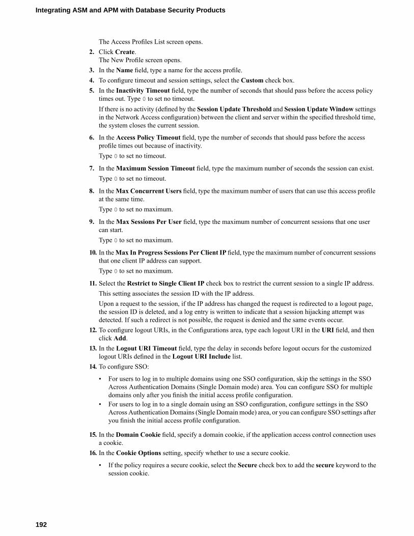
The Access Profiles List screen opens.2. Click Create.
The New Profile screen opens.3. In the Name field, type a name for the access profile.4. To configure timeout and session settings, select the Custom check box.5. In the Inactivity Timeout field, type the number of seconds that should pass before the access policy
times out. Type 0 to set no timeout.If there is no activity (defined by the Session Update Threshold and Session UpdateWindow settingsin the Network Access configuration) between the client and server within the specified threshold time,the system closes the current session.
6. In the Access Policy Timeout field, type the number of seconds that should pass before the accessprofile times out because of inactivity.Type 0 to set no timeout.
7. In theMaximum Session Timeout field, type the maximum number of seconds the session can exist.Type 0 to set no timeout.
8. In theMax Concurrent Users field, type the maximum number of users that can use this access profileat the same time.Type 0 to set no maximum.
9. In theMax Sessions Per User field, type the maximum number of concurrent sessions that one usercan start.Type 0 to set no maximum.
10. In theMax In Progress Sessions Per Client IP field, type the maximum number of concurrent sessionsthat one client IP address can support.Type 0 to set no maximum.
11. Select the Restrict to Single Client IP check box to restrict the current session to a single IP address.This setting associates the session ID with the IP address.Upon a request to the session, if the IP address has changed the request is redirected to a logout page,the session ID is deleted, and a log entry is written to indicate that a session hijacking attempt wasdetected. If such a redirect is not possible, the request is denied and the same events occur.
12. To configure logout URIs, in the Configurations area, type each logout URI in the URI field, and thenclick Add.
13. In the Logout URI Timeout field, type the delay in seconds before logout occurs for the customizedlogout URIs defined in the Logout URI Include list.
14. To configure SSO:
• For users to log in to multiple domains using one SSO configuration, skip the settings in the SSOAcross Authentication Domains (Single Domain mode) area. You can configure SSO for multipledomains only after you finish the initial access profile configuration.
• For users to log in to a single domain using an SSO configuration, configure settings in the SSOAcross AuthenticationDomains (Single Domainmode) area, or you can configure SSO settings afteryou finish the initial access profile configuration.
15. In the Domain Cookie field, specify a domain cookie, if the application access control connection usesa cookie.
16. In the Cookie Options setting, specify whether to use a secure cookie.
• If the policy requires a secure cookie, select the Secure check box to add the secure keyword to thesession cookie.
192
Integrating ASM and APM with Database Security Products

• If you are configuring an LTM access scenario that uses an HTTPS virtual server to authenticate theuser and then sends the user to an existing HTTP virtual server to use applications, clear this checkbox.
17. If the access policy requires a persistent cookie, in the Cookie Options setting, select the Persistentcheck box.This sets cookies if the session does not have a webtop. When the session is first established, sessioncookies are not marked as persistent; but when the first response is sent to the client after the accesspolicy completes successfully, the cookies are marked persistent. Persistent cookies are updated for theexpiration timeout every 60 seconds. The timeout is equal to session inactivity timeout. If the sessioninactivity timeout is overwritten in the access policy, the overwritten value will be used to set thepersistent cookie expiration.
18. From the SSO Configurations list, select an SSO configuration.19. In the Language Settings area, add and remove accepted languages, and set the default language.
A browser uses the highest priority accepted language. If no browser language matches the acceptedlanguages list, the browser uses the default language.
20. Click Finished.
The access profile appears in the Access Profiles List.
To add an SSO configuration for multiple domains, click SSO / Auth Domains on the menu bar. To providefunctionality with an access profile, you must configure the access policy. The default access policy for aprofile denies all traffic and contains no actions. Click Edit in the Access Policy column to edit the accesspolicy.
Configuring an access policy
You configure an access policy to provide authentication, endpoint checks, and resources for an accessprofile. This procedure configures a simple access policy that adds a logon page, gets user credentials,submits them to an authentication type of your choice, then allows authenticated users, and denies others.
1. On the Main tab, click Access Policy > Access Profiles.The Access Profiles List screen opens.
2. Click the name of the access profile you want to edit.3. On the menu bar, click Access Policy.4. For the Visual Policy Editor setting, click the Edit access policy for Profile policy_name link.
The visual policy editor opens the access policy in a separate window or tab.5. Click the (+) sign anywhere in the access policy to add a new action item.
An Add Item screen opens, listing predefined actions on tabs such as General Purpose, Authentication,and so on.
6. On the Logon tab, select Logon Page and click the Add Item button.The Logon Page Agent properties screen opens.
7. Click Save.The Access Policy screen reopens.
8. On the rule branch, click the plus sign (+) between Logon Page and Deny.9. Set up the appropriate authentication and client-side checks required for application access at your
company, and click Add Item.10. Change the Successful rule branch from Deny to Allow and click the Save button.11. If needed, configure further actions on the successful and fallback rule branches of this access policy
item, and save the changes.
193
BIG-IP® Application Security Manager™: Implementations

12. At the top of the screen, click the Apply Access Policy link to apply and activate your changes to thisaccess policy.
13. Click the Close button to close the visual policy editor.
Adding the access profile to the virtual server
Before you can perform this task, you need to create an access profile using Access Policy Manager™.
You associate the access profile with the virtual server created for the web application that ApplicationSecurity Manager™ is protecting.
1. On the Main tab, click Local Traffic > Virtual Servers.The Virtual Server List screen opens.
2. Click the name of the virtual server that manages the network resources for the web application you aresecuring.
3. In the Access Policy area, from the Access Profile list, select the access profile.4. Click Update.
Your access policy is now associated with the virtual server.
Configuring a database security server
To integrate Application Security Manager™ (ASM) with a third-party database security product, you needto configure the database security server on ASM™. You can configure one database security server persystem.
1. On the Main tab, click Security >Options > Application Security > Integrated Services > DatabaseSecurity.The Database Security screen opens.
2. Specify the database security server by typing either its Server Host Name or its Server IP Address.Only one of the two fields is required.
Note: If using SSL to establish a secured session between the BIG-IP ®system and the database securityserver, type the IP address of a virtual server configured for the secure connection. The virtual serveruses any open IP address for the destination, the IBM Guardium port (16016, by default) for the serviceport, serverssl or a customized profile for the SSL Profile (Server) setting, and specifies a defaultpool (containing one member, the database security server, using its IP address and service port,typically, 16016).
3. For Server Port Number, type the port number of the database server.The default value is 16016, the port used by IBM® InfoSphere® Guardium.®
4. If you want the system to wait for an ACK response from the database security server before sendingthe request to the application server, from the Request Hold Timeout list, select Enabled and type thenumber of milliseconds to wait for the response.The default value is 5 milliseconds.When this setting is enabled, the system forwards the request to the application server as soon as thedatabase security server sends an ACK, or when the timeout has passed. If you leave this setting disabled,the system forwards the request to the application server immediately.
5. Click Save.
194
Integrating ASM and APM with Database Security Products

The system saves the configuration settings.
The Application Security Manager is now configured to connect to the database security server.
For ASM to forward request data to the database security server, you next need to enable database securityintegration in one or more security policies.
Enabling database security integration with ASM and APM
Before you can enable database security integration, you need to have created a security policy to protectyour web application. For the policy to retrieve the user names of those making requests, you need to haveset up Access Policy Manager®(APM™) on the BIG-IP® system.
You enable database security integration in a security policy so that Application Security Manager™ (ASM)forwards request information to a third-party database server.
1. On the Main tab, click Security > Application Security > Integrated Services > Database Security.The Database Security screen opens.
2. In the Current edited policy list near the top of the screen, verify that the edited security policy is theone you want to work on.
3. Select the Database Security Integration check box.4. For User Source, select Use APM Usernames and Session ID.
The system uses Access PolicyManager (APM) user names and session ID to determine the user source.You can choose this option only if you have APM licensed and provisioned.
5. Click Save.The system saves the configuration settings.
The Application Security Manager connects to the database security server and can forward request datato it.
Implementation result
You have set up a BIG-IP® system to use Application Security Manager™ (ASM) to secure applicationtraffic, and Access Policy Manager™ (APM) to check user credentials.
Client traffic is routed to the virtual server for the web application. At first, traffic is handled by the APMmodule. APM™ verifies user credentials and allows those with valid credentials to use web application.APM also sends user names and session IDs of valid users to ASM™. After that, ASM checks for securityviolations and forwards traffic that meets the security policy requirements to the backend server.
The database security server includes the application and user information provided by ASM and APM, soit can be viewed in logs and reports on that system. The database security server can perform a more indepth security assessment of the web request.
If you want to review reports and event logs that associate the user name with the session information onthe BIG-IP system, you can set up session tracking (by enabling session awareness).When session awarenessis enabled, you can see the user names on the Event Logs: Application: Requests screen in the GeneralDetails section of specific requests. IN addition, the Reporting: Application: Charts screen displays theusers who sent the illegal requests.
195
BIG-IP® Application Security Manager™: Implementations

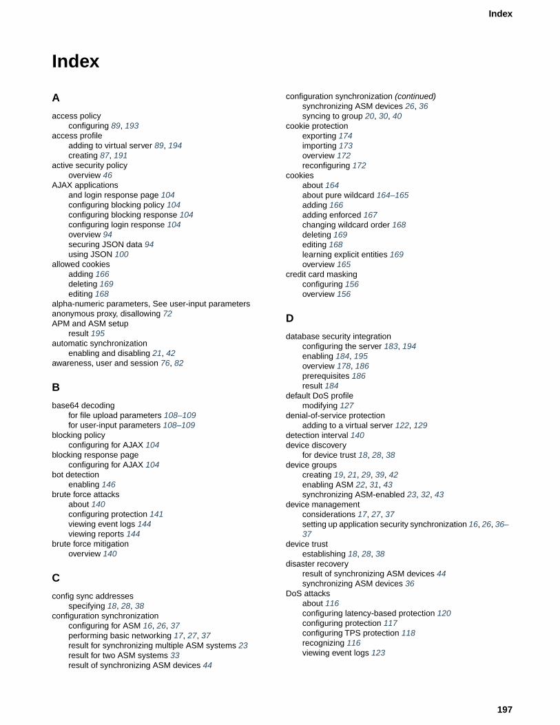
Index
A
access policyconfiguring 89, 193
access profileadding to virtual server 89, 194creating 87, 191
active security policyoverview 46
AJAX applicationsand login response page 104configuring blocking policy 104configuring blocking response 104configuring login response 104overview 94securing JSON data 94using JSON 100
allowed cookiesadding 166deleting 169editing 168
alpha-numeric parameters, See user-input parametersanonymous proxy, disallowing 72APM and ASM setup
result 195automatic synchronization
enabling and disabling 21, 42awareness, user and session 76, 82
B
base64 decodingfor file upload parameters 108–109for user-input parameters 108–109
blocking policyconfiguring for AJAX 104
blocking response pageconfiguring for AJAX 104
bot detectionenabling 146
brute force attacksabout 140configuring protection 141viewing event logs 144viewing reports 144
brute force mitigationoverview 140
C
config sync addressesspecifying 18, 28, 38
configuration synchronizationconfiguring for ASM 16, 26, 37performing basic networking 17, 27, 37result for synchronizing multiple ASM systems 23result for two ASM systems 33result of synchronizing ASM devices 44
configuration synchronization (continued)synchronizing ASM devices 26, 36syncing to group 20, 30, 40
cookie protectionexporting 174importing 173overview 172reconfiguring 172
cookiesabout 164about pure wildcard 164–165adding 166adding enforced 167changing wildcard order 168deleting 169editing 168learning explicit entities 169overview 165
credit card maskingconfiguring 156overview 156
D
database security integrationconfiguring the server 183, 194enabling 184, 195overview 178, 186prerequisites 186result 184
default DoS profilemodifying 127
denial-of-service protectionadding to a virtual server 122, 129
detection interval 140device discovery
for device trust 18, 28, 38device groups
creating 19, 21, 29, 39, 42enabling ASM 22, 31, 43synchronizing ASM-enabled 23, 32, 43
device managementconsiderations 17, 27, 37setting up application security synchronization 16, 26, 36–37
device trustestablishing 18, 28, 38
disaster recoveryresult of synchronizing ASM devices 44synchronizing ASM devices 36
DoS attacksabout 116configuring latency-based protection 120configuring protection 117configuring TPS protection 118recognizing 116viewing event logs 123
197
Index

DoS policy switchingcreating LTM policy 128creating LTM policy rules 128overview 126result 130
DoS profilecreating for Layer 7 traffic 127modifying default 127
DoS profilesassociating with virtual servers 122, 129
DoS protectionabout latency-based 117about TPS-based 116
DoS protection setupoverview 117result 123
E
enforced cookiesadding 167deleting 169editing 168
enforcement, login 77–78, 182explicit entities
adding cookies 169export formats
about 50
F
failover IP addressesspecifying 21, 31, 41
file upload parameters, See user-input parameters
G
geolocationenforcing 72enforcing from Requests list 73overview 72
Google Web ToolkitGWT 112see GWT 112
GWTadding to support security policies 112
GWT profileand implementation result 114associating with URL 113creating 112
H
header normalizationabout 158
history interval 140HTTP-GET attacks
about 116HTTP headers
about mandatory 158
HTTP header securityconfiguring 159overview 158–159results 160
HTTPS trafficcreating virtual servers for 84, 188
I
IBM InfoSphere Guardium integrationconfiguring the server 183, 194enabling 184, 195overview 178, 186
IP address exceptionscreating 68deleting 69overview 68updating 69
IP address intelligencecategories 66downloading the database 62enabling 62logging information 64rejecting bad requests 65
IP address intelligence blockingoverview 62reviewing statistics 64setting up 63
IP intelligence database 66iprep.autoupdate command 62IP reputation blocking
overview 62
J
JSON datamasking 100
JSON profilecreating 100
L
latency-based DoS detection 117latency-based DoS protection
configuring 120local traffic policies
and ASM 134, 138and manual ASM policies 134
local traffic policyassociating with virtual servers 130creating ASM rules 137creating for DoS 128creating rules 128
local traffic poolscreating 83, 188
local trust domainand device groups 19, 21, 29, 39, 42defined 18, 28, 38
loggingof IP address intelligence information 64
login enforcement 77, 182
198
Index

login pagescreating 76, 140, 181enforcing 77, 182
login response pageconfiguring for AJAX 104
M
malicious IP address 63mandatory headers
about 158merge feature
overview 58
N
network failoverconfiguring 19, 29, 39
normalization for headersabout 158
P
page flood attacksabout 116
parametersassociating with JSON profiles 102securing base64-encoded 108
parameters pathenforcing security 176overview 176
path parametersenforcing security 176overview 176
policy, See security policy.policy differences
54merging 58
Policy Diff featureoverview 54
poolscreating local traffic 83, 188
profilesassociating parameters with JSON 102associating URLs with GWT 113associating URLs with JSON 101creating GWT 112creating JSON 100
pure wildcard cookies 164–165
R
reportingfor IP address intelligence blocking 64
ruleslocal traffic policy 137
S
security policiesand local traffic policies 134, 138
security policies (continued)and manually adding local traffic policies 134
security policyabout export formats 50activating 46comparing 54creating automatically 84, 94, 135, 179, 189deactivating 46deleting 47exporting 50import/export overview 50importing 51merging 58overview merging 58reviewing status 97synchronizing ASM 23, 32, 43
security policy activationoverview 46
security policy deactivationoverview 46
security policy synchronizationconfiguring 16, 26, 36–37
self IP addressesand VLANs 83, 187creating 83, 187
sensitive datamasking credit card numbers 156masking JSON 100
session awarenessenabling 78enabling with APM 90
session opening detectionenabling 148
sessions, monitoring 79, 91session tracking
enabling 78enabling with APM 90overview 76, 82prerequisites 82
session transaction anomaliesenabling detection 150
Sync-Failover device groupscreating 19, 29, 39
synchronizationconfiguring for ASM 26, 36result for configuring multiple ASM systems 23result for configuring two ASM systems 33
Sync-Only device groupscreating 21, 42
T
TPS DoS protectionconfiguring 118
transaction rateabout detection 116
trust domainsand local trust domain 18, 28, 38
199
Index
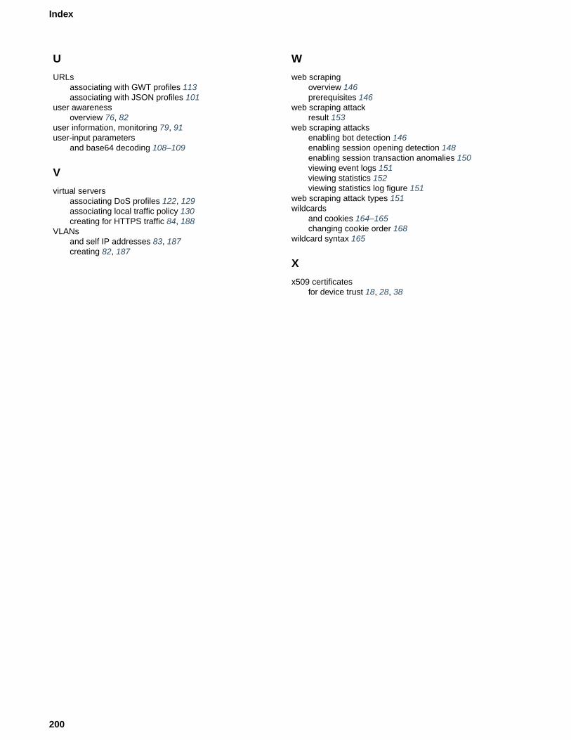
U
URLsassociating with GWT profiles 113associating with JSON profiles 101
user awarenessoverview 76, 82
user information, monitoring 79, 91user-input parameters
and base64 decoding 108–109
V
virtual serversassociating DoS profiles 122, 129associating local traffic policy 130creating for HTTPS traffic 84, 188
VLANsand self IP addresses 83, 187creating 82, 187
W
web scrapingoverview 146prerequisites 146
web scraping attackresult 153
web scraping attacksenabling bot detection 146enabling session opening detection 148enabling session transaction anomalies 150viewing event logs 151viewing statistics 152viewing statistics log figure 151
web scraping attack types 151wildcards
and cookies 164–165changing cookie order 168
wildcard syntax 165
X
x509 certificatesfor device trust 18, 28, 38
200
Index


![[ASM] Lab2](https://static.fdocuments.in/doc/165x107/588121881a28abb9388b7069/asm-lab2.jpg)