BIG-IP® Acceleration: Network Configuration · BIG-IP® Acceleration: Network Configuration....
150
BIG-IP ® Acceleration: Network Configuration Version 11.5
Transcript of BIG-IP® Acceleration: Network Configuration · BIG-IP® Acceleration: Network Configuration....
BIG-IP® Acceleration: NetworkConfiguration
Version 11.5

Table of Contents
Legal Notices.....................................................................................................9
Acknowledgments...........................................................................................11
Chapter 1: Configuring Global Network Acceleration..........................................................15
Overview: Configuring Global Network Acceleration........................................................16
Deployment of BIG-IP Devices for Acceleration....................................................16
About symmetric request and response headers..................................................17
Working with Sync-Only device groups............................................................................17
What is device trust?........................................................................................................17
Illustration of Sync-Only device group configuration........................................................18
Device identity..................................................................................................................18
Task summary..................................................................................................................18
Defining an NTP server.........................................................................................19
Adding a device to the local trust domain..............................................................19
Creating a Sync-Only device group.......................................................................20
Syncing the BIG-IP configuration to the device group...........................................21
Task summary for accelerating HTTP traffic with a Central BIG-IP Device......................21
Defining an NTP server.........................................................................................21
Creating a new folder for synchronized acceleration applications.........................22
Creating a user-defined acceleration policy from a predefined acceleration
policy................................................................................................................22
Creating an application profile for a symmetric deployment..................................23
Enabling acceleration with the Web Acceleration profile.......................................23
Creating a pool on a central BIG-IP device to process synchronized HTTP
traffic.................................................................................................................24
Creating a virtual server to manage HTTP traffic..................................................24
Using Quick Start to set up iSession endpoints....................................................25
Adding a virtual server to advertised routes..........................................................26
Task summary for accelerating HTTP traffic with a Remote BIG-IP Device.....................26
Defining an NTP server.........................................................................................26
Enabling acceleration with the Web Acceleration profile.......................................27
Creating a virtual server to manage HTTP traffic..................................................27
Using Quick Start to set up iSession endpoints....................................................28
Clearing a Remote BIG-IP Device cache..............................................................28
Implementation results.....................................................................................................29
Chapter 2: Configuring Global Network Acceleration for Web Application.......................31
Overview: Configuring Global Network Acceleration for Web Application........................32
Deployment of BIG-IP Devices for Acceleration....................................................32
About symmetric request and response headers..................................................33
3
Table of Contents
Working with Sync-Only device groups............................................................................33
What is device trust?........................................................................................................33
Illustration of Sync-Only device group configuration........................................................34
Device identity..................................................................................................................34
Task summary..................................................................................................................35
Defining an NTP server.........................................................................................35
Adding a device to the local trust domain..............................................................35
Creating a Sync-Only device group.......................................................................36
Syncing the BIG-IP configuration to the device group...........................................37
Task summary for accelerating HTTP traffic with a Central BIG-IP Device......................37
Defining an NTP server.........................................................................................38
Creating a new folder for synchronized acceleration applications.........................38
Creating a user-defined acceleration policy from a predefined acceleration
policy................................................................................................................38
Creating an application profile for a symmetric deployment..................................39
Enabling acceleration with the Web Acceleration profile.......................................39
Creating a pool on a central BIG-IP device to process synchronized HTTP
traffic.................................................................................................................40
Creating a virtual server to manage HTTP traffic..................................................40
Task summary for accelerating HTTP traffic with a Remote BIG-IP Device.....................41
Defining an NTP server.........................................................................................41
Enabling acceleration with the Web Acceleration profile.......................................42
Creating a virtual server to manage HTTP traffic..................................................42
Clearing a Remote BIG-IP Device cache..............................................................43
Implementation results.....................................................................................................43
Chapter 3: Configuring Acceleration for a Server Farm.......................................................45
Overview: Configuring Acceleration for a Server Farm....................................................46
About BIG-IP acceleration in a server farm...........................................................46
Working with Sync-Only device groups............................................................................46
What is device trust?........................................................................................................47
Illustration of Sync-Only device group configuration........................................................47
Device identity..................................................................................................................48
Task summary..................................................................................................................48
Defining an NTP server.........................................................................................48
Adding a device to the local trust domain..............................................................49
Creating a Sync-Only device group.......................................................................49
Syncing the BIG-IP configuration to the device group...........................................50
Task summary for configuring Acceleration for a Server Farm........................................51
Defining an NTP server.........................................................................................51
Creating a new folder for synchronized acceleration applications.........................51
Creating a user-defined acceleration policy from a predefined acceleration
policy................................................................................................................52
Creating an application profile for a server farm deployment................................52
4
Table of Contents

Enabling acceleration with the Web Acceleration profile.......................................53
Creating a pool on a central BIG-IP device to process synchronized HTTP
traffic.................................................................................................................53
Creating a virtual server to manage HTTP traffic..................................................54
Implementation results.....................................................................................................54
Chapter 4: Configuring Acceleration with an Asymmetric BIG-IP System........................55
About an asymmetric BIG-IP deployment........................................................................56
Task summary for configuring Acceleration with an asymmetric BIG-IP system.............56
Defining an NTP server.........................................................................................56
Creating a new folder for synchronized acceleration applications.........................57
Creating a user-defined acceleration policy from a predefined acceleration
policy................................................................................................................57
Creating a BIG-IP application profile for an asymmetric acceleration
deployment.......................................................................................................57
Enabling acceleration with the Web Acceleration profile.......................................58
Creating a pool to process HTTP traffic................................................................58
Creating a virtual server to manage HTTP traffic..................................................59
Implementation result.......................................................................................................59
Chapter 5: Setting Up an iSession Connection Using the Quick Start Screen..................61
Overview: Setting up an iSession connection using the Quick Start screen....................62
Setting up an iSession connection using the Quick Start screen..........................62
Chapter 6: Troubleshooting the iSession Configuration.....................................................65
About symmetric optimization diagnostics.......................................................................66
Symmetric optimization diagnostic error messages.........................................................66
Troubleshooting network connectivity for iSession configurations...................................67
Running symmetric optimization configuration diagnostics..............................................67
Chapter 7: Configuring a One-Arm Deployment Using WCCPv2........................................69
Overview: Configuring a one-arm deployment using WCCPv2........................................70
About WCCPv2 redirection on the BIG-IP system...........................................................70
Before you begin configuring an iSession connection.....................................................71
Task summary..................................................................................................................72
Creating a VLAN for a one-arm deployment.........................................................72
Creating a self IP address for a one-arm deployment...........................................73
Defining a route.....................................................................................................74
Configuring WCCPv2............................................................................................74
Verifying connectivity.............................................................................................76
Verifying WCCPv2 configuration for one-arm deployment....................................77
Creating an iSession connection...........................................................................77
Validating iSession configuration in a one-arm deployment..................................79
5
Table of Contents

Configuring the Cisco router for a one-arm deployment using WCCPv2..............79
Viewing pertinent configuration details from the command line............................81
Implementation result.......................................................................................................86
Chapter 8: Configuring a BIG-IP System with iSession in Bridge Mode............................87
Overview: Configuring the BIG-IP system in bridge mode...............................................88
Illustration of a bridge deployment...................................................................................88
Before you begin configuring an iSession connection.....................................................88
Task summary..................................................................................................................89
Creating VLANs.....................................................................................................89
Creating a VLAN group.........................................................................................90
Creating a self IP address for a VLAN group........................................................91
Defining a route.....................................................................................................92
Checking connectivity............................................................................................92
Setting up an iSession connection using the Quick Start screen..........................92
Validating iSession configuration...........................................................................94
Viewing pertinent configuration details from the command line............................95
Implementation result.....................................................................................................101
Chapter 9: Configuring a BIG-IP System with iSession in Routed Mode.........................103
Overview: Configuring the BIG-IP system in routed mode.............................................104
Illustration of a routed deployment.................................................................................104
About symmetric optimization using iSession on BIG-IP systems.................................104
Before you begin configuring an iSession connection...................................................105
Task summary................................................................................................................106
Creating VLANs...................................................................................................106
Creating self IP addresses for internal and external VLANs...............................107
Creating a default gateway..................................................................................107
Creating a passthrough virtual server.................................................................108
Checking connectivity..........................................................................................108
Setting up an iSession connection using the Quick Start screen........................108
Validating iSession configuration.........................................................................110
Viewing pertinent configuration details from the command line..........................111
Implementation result.....................................................................................................118
Chapter 10: Setting Up iSession and IPsec To Use NAT Traversal on Both Sides of
the WAN..............................................................................................................................119
Overview: Setting up iSession and IPsec to use NAT traversal on both sides...............120
Before you begin IPsec configuration.............................................................................120
Task summary................................................................................................................120
Creating a forwarding virtual server for IPsec.....................................................121
Creating an IPsec tunnel with NAT-T on both sides............................................121
Verifying IPsec connectivity for Tunnel mode......................................................125
Using Quick Start to set up iSession endpoints..................................................128
6
Table of Contents
Chapter 11: Setting Up iSession and IPsec To Use NAT Traversal on One Side of the
WAN....................................................................................................................................131
Overview: Setting up iSession and IPsec to use NAT traversal on one side..................132
Before you begin IPsec configuration.............................................................................132
Task summary................................................................................................................132
Creating a forwarding virtual server for IPsec.....................................................133
Creating an IPsec tunnel with NAT-T on one side...............................................133
Verifying IPsec connectivity for Tunnel mode......................................................137
Using Quick Start to set up iSession endpoints..................................................141
Chapter 12: Disk Management for Datastor........................................................................143
About disk management................................................................................................144
Task summary................................................................................................................144
Provisioning extra VE disk for datastor................................................................144
Provisioning solid-state drives for datastor..........................................................145
Monitoring SSD usage........................................................................................146
7
Table of Contents

8
Table of Contents

Legal Notices
Publication Date
This document was published on January 27, 2014.
Publication Number
MAN-0466-02
Copyright
Copyright © 2013-2014, F5 Networks, Inc. All rights reserved.
F5 Networks, Inc. (F5) believes the information it furnishes to be accurate and reliable. However, F5 assumesno responsibility for the use of this information, nor any infringement of patents or other rights of thirdparties which may result from its use. No license is granted by implication or otherwise under any patent,copyright, or other intellectual property right of F5 except as specifically described by applicable userlicenses. F5 reserves the right to change specifications at any time without notice.
Trademarks
AAM, Access Policy Manager, Advanced Client Authentication, Advanced Firewall Manager, AdvancedRouting, AFM, APM, Application Acceleration Manager, Application Security Manager, ARX, AskF5,ASM, BIG-IP, BIG-IQ, Cloud Extender, CloudFucious, Cloud Manager, Clustered Multiprocessing, CMP,COHESION, Data Manager, DevCentral, DevCentral [DESIGN], DNS Express, DSC, DSI, Edge Client,Edge Gateway, Edge Portal, ELEVATE, EM, EnterpriseManager, ENGAGE, F5, F5 [DESIGN], F5 Certified[DESIGN], F5 Networks, F5 SalesXchange [DESIGN], F5 Synthesis, f5 Synthesis, F5 Synthesis [DESIGN],F5 TechXchange [DESIGN], Fast Application Proxy, Fast Cache, FirePass, Global Traffic Manager, GTM,GUARDIAN, iApps, IBR, Intelligent Browser Referencing, Intelligent Compression, IPv6 Gateway,iControl, iHealth, iQuery, iRules, iRules OnDemand, iSession, L7 Rate Shaping, LC, Link Controller, LocalTraffic Manager, LTM, LineRate, LineRate Systems [DESIGN], LROS, LTM, Message Security Manager,MSM, OneConnect, Packet Velocity, PEM, Policy Enforcement Manager, Protocol Security Manager,PSM, Real Traffic Policy Builder, SalesXchange, ScaleN, Signalling Delivery Controller, SDC, SSLAcceleration, software designed applications services, SDAC (except in Japan), StrongBox, SuperVIP,SYN Check, TCP Express, TDR, TechXchange, TMOS, TotALL, Traffic Management Operating System,Traffix Systems, Traffix Systems (DESIGN), Transparent Data Reduction, UNITY, VAULT, vCMP, VEF5 [DESIGN], Versafe, Versafe [DESIGN], VIPRION, Virtual Clustered Multiprocessing, WebSafe, andZoneRunner, are trademarks or service marks of F5 Networks, Inc., in the U.S. and other countries, andmay not be used without F5's express written consent.
All other product and company names herein may be trademarks of their respective owners.
Patents
This product may be protected by one or more patents indicated at:http://www.f5.com/about/guidelines-policies/patents
Export Regulation Notice
This product may include cryptographic software. Under the Export Administration Act, the United Statesgovernment may consider it a criminal offense to export this product from the United States.

RF Interference Warning
This is a Class A product. In a domestic environment this product may cause radio interference, in whichcase the user may be required to take adequate measures.
FCC Compliance
This equipment has been tested and found to comply with the limits for a Class A digital device pursuantto Part 15 of FCC rules. These limits are designed to provide reasonable protection against harmfulinterference when the equipment is operated in a commercial environment. This unit generates, uses, andcan radiate radio frequency energy and, if not installed and used in accordance with the instruction manual,may cause harmful interference to radio communications. Operation of this equipment in a residential areais likely to cause harmful interference, in which case the user, at his own expense, will be required to takewhatever measures may be required to correct the interference.
Anymodifications to this device, unless expressly approved by themanufacturer, can void the user's authorityto operate this equipment under part 15 of the FCC rules.
Canadian Regulatory Compliance
This Class A digital apparatus complies with Canadian ICES-003.
Standards Compliance
This product conforms to the IEC, European Union, ANSI/UL and Canadian CSA standards applicable toInformation Technology products at the time of manufacture.
10
Legal Notices

Acknowledgments
This product includes software developed by Bill Paul.
This product includes software developed by Jonathan Stone.
This product includes software developed by Manuel Bouyer.
This product includes software developed by Paul Richards.
This product includes software developed by the NetBSD Foundation, Inc. and its contributors.
This product includes software developed by the Politecnico di Torino, and its contributors.
This product includes software developed by the Swedish Institute of Computer Science and its contributors.
This product includes software developed by the University of California, Berkeley and its contributors.
This product includes software developed by the Computer Systems Engineering Group at the LawrenceBerkeley Laboratory.
This product includes software developed by Christopher G. Demetriou for the NetBSD Project.
This product includes software developed by Adam Glass.
This product includes software developed by Christian E. Hopps.
This product includes software developed by Dean Huxley.
This product includes software developed by John Kohl.
This product includes software developed by Paul Kranenburg.
This product includes software developed by Terrence R. Lambert.
This product includes software developed by Philip A. Nelson.
This product includes software developed by Herb Peyerl.
This product includes software developed by Jochen Pohl for the NetBSD Project.
This product includes software developed by Chris Provenzano.
This product includes software developed by Theo de Raadt.
This product includes software developed by David Muir Sharnoff.
This product includes software developed by SigmaSoft, Th. Lockert.
This product includes software developed for the NetBSD Project by Jason R. Thorpe.
This product includes software developed by Jason R. Thorpe for AndCommunications, http://www.and.com.
This product includes software developed for the NetBSD Project by Frank Van der Linden.
This product includes software developed for the NetBSD Project by John M. Vinopal.
This product includes software developed by Christos Zoulas.
This product includes software developed by the University of Vermont and State Agricultural College andGarrett A. Wollman.
This product includes software developed by Balazs Scheidler ([email protected]), which is protected underthe GNU Public License.
This product includes software developed by Niels Mueller ([email protected]), which is protected underthe GNU Public License.

In the following statement, This software refers to theMitsumi CD-ROMdriver: This software was developedby Holger Veit and Brian Moore for use with 386BSD and similar operating systems. Similar operatingsystems includes mainly non-profit oriented systems for research and education, including but not restrictedto NetBSD, FreeBSD, Mach (by CMU).
This product includes software developed by the Apache Group for use in the Apache HTTP server project(http://www.apache.org/).
This product includes software licensed from Richard H. Porter under the GNU Library General PublicLicense (© 1998, Red Hat Software), www.gnu.org/copyleft/lgpl.html.
This product includes the standard version of Perl software licensed under the Perl Artistic License (© 1997,1998 TomChristiansen and Nathan Torkington). All rights reserved. Youmay find the most current standardversion of Perl at http://www.perl.com.
This product includes software developed by Jared Minch.
This product includes software developed by the OpenSSL Project for use in the OpenSSL Toolkit(http://www.openssl.org/).
This product includes cryptographic software written by Eric Young ([email protected]).
This product contains software based on oprofile, which is protected under the GNU Public License.
This product includes RRDtool software developed by Tobi Oetiker (http://www.rrdtool.com/index.html)and licensed under the GNU General Public License.
This product contains software licensed from Dr. Brian Gladman under the GNU General Public License(GPL).
This product includes software developed by the Apache Software Foundation (http://www.apache.org/).
This product includes Hypersonic SQL.
This product contains software developed by the Regents of the University of California, SunMicrosystems,Inc., Scriptics Corporation, and others.
This product includes software developed by the Internet Software Consortium.
This product includes software developed by Nominum, Inc. (http://www.nominum.com).
This product contains software developed by Broadcom Corporation, which is protected under the GNUPublic License.
This product contains software developed byMaxMind LLC, and is protected under the GNULesser GeneralPublic License, as published by the Free Software Foundation.
This product includes Intel QuickAssist kernel module, library, and headers software licensed under theGNU General Public License (GPL).
This product includes software licensed fromGerald Combs ([email protected]) under the GNUGeneralPublic License as published by the Free Software Foundation; either version 2 of the License, or any laterversion. Copyright ©1998 Gerald Combs.
This product includes software developed by Thomas Williams and Colin Kelley. Copyright ©1986 - 1993,1998, 2004, 2007
Permission to use, copy, and distribute this software and its documentation for any purpose with or withoutfee is hereby granted, provided that the above copyright notice appear in all copies and that both thatcopyright notice and this permission notice appear in supporting documentation. Permission to modify thesoftware is granted, but not the right to distribute the complete modified source code. Modifications are tobe distributed as patches to the released version. Permission to distribute binaries produced by compilingmodified sources is granted, provided you
1. distribute the corresponding source modifications from the released version in the form of a patch filealong with the binaries,
12
Acknowledgments
2. add special version identification to distinguish your version in addition to the base release versionnumber,
3. provide your name and address as the primary contact for the support of your modified version, and4. retain our contact information in regard to use of the base software.
Permission to distribute the released version of the source code alongwith corresponding sourcemodificationsin the form of a patch file is granted with same provisions 2 through 4 for binary distributions. This softwareis provided "as is" without express or implied warranty to the extent permitted by applicable law.
This product includes software developed by the Computer Systems Engineering Group at LawrenceBerkeley Laboratory. Copyright ©1990-1994 Regents of the University of California. All rights reserved.Redistribution and use in source and binary forms, with or without modification, are permitted providedthat the following conditions are met:
1. Redistributions of source code must retain the above copyright notice, this list of conditions and thefollowing disclaimer.
2. Redistributions in binary form must reproduce the above copyright notice, this list of conditions and thefollowing disclaimer in the documentation and/or other materials provided with the distribution.
3. All advertising materials mentioning features or use of this software must display the followingacknowledgment: This product includes software developed by the Computer Systems EngineeringGroup at Lawrence Berkeley Laboratory.
4. Neither the name of the University nor of the Laboratory may be used to endorse or promote productsderived from this software without specific prior written permission.
THIS SOFTWARE IS PROVIDED BY THE REGENTS AND CONTRIBUTORS "AS IS" AND ANYEXPRESS OR IMPLIED WARRANTIES, INCLUDING, BUT NOT LIMITED TO, THE IMPLIEDWARRANTIES OF MERCHANTABILITY AND FITNESS FOR A PARTICULAR PURPOSE AREDISCLAIMED. IN NO EVENT SHALL THE REGENTS OR CONTRIBUTORS BE LIABLE FOR ANYDIRECT, INDIRECT, INCIDENTAL, SPECIAL, EXEMPLARY, OR CONSEQUENTIAL DAMAGES(INCLUDING, BUT NOT LIMITED TO, PROCUREMENTOF SUBSTITUTEGOODSOR SERVICES;LOSS OF USE, DATA, OR PROFITS; OR BUSINESS INTERRUPTION) HOWEVER CAUSED ANDON ANY THEORY OF LIABILITY, WHETHER IN CONTRACT, STRICT LIABILITY, OR TORT(INCLUDINGNEGLIGENCEOROTHERWISE) ARISING INANYWAYOUTOF THEUSEOF THISSOFTWARE, EVEN IF ADVISED OF THE POSSIBILITY OF SUCH DAMAGE.
This product includes software developed by Sony Computer Science Laboratories Inc. Copyright ©1997-2003 Sony Computer Science Laboratories Inc. All rights reserved. Redistribution and use in sourceand binary forms, with or without modification, are permitted provided that the following conditions aremet:
1. Redistributions of source code must retain the above copyright notice, this list of conditions and thefollowing disclaimer.
2. Redistributions in binary form must reproduce the above copyright notice, this list of conditions and thefollowing disclaimer in the documentation and/or other materials provided with the distribution.
THISSOFTWARE ISPROVIDEDBYSONYCSLANDCONTRIBUTORS "AS IS"ANDANYEXPRESSOR IMPLIEDWARRANTIES, INCLUDING, BUT NOT LIMITED TO, THE IMPLIEDWARRANTIESOF MERCHANTABILITY AND FITNESS FOR A PARTICULAR PURPOSE ARE DISCLAIMED. INNO EVENT SHALL SONY CSL OR CONTRIBUTORS BE LIABLE FOR ANY DIRECT, INDIRECT,INCIDENTAL, SPECIAL, EXEMPLARY, OR CONSEQUENTIAL DAMAGES (INCLUDING, BUTNOT LIMITED TO, PROCUREMENT OF SUBSTITUTE GOODS OR SERVICES; LOSS OF USE,DATA,ORPROFITS;ORBUSINESS INTERRUPTION)HOWEVERCAUSEDANDONANYTHEORYOF LIABILITY, WHETHER IN CONTRACT, STRICT LIABILITY, OR TORT (INCLUDINGNEGLIGENCE OR OTHERWISE) ARISING IN ANYWAY OUT OF THE USE OF THIS SOFTWARE,EVEN IF ADVISED OF THE POSSIBILITY OF SUCH DAMAGE.
This product contains software developed by Google, Inc. Copyright ©2011 Google, Inc.
13
BIG-IP® Acceleration: Network Configuration

Permission is hereby granted, free of charge, to any person obtaining a copy of this software and associateddocumentation files (the "Software"), to deal in the Software without restriction, including without limitationthe rights to use, copy, modify, merge, publish, distribute, sublicense, and/or sell copies of the Software,and to permit persons to whom the Software is furnished to do so, subject to the following conditions:
The above copyright notice and this permission notice shall be included in all copies or substantial portionsof the Software.
THE SOFTWARE IS PROVIDED "AS IS", WITHOUT WARRANTY OF ANY KIND, EXPRESS ORIMPLIED, INCLUDING BUT NOT LIMITED TO THE WARRANTIES OF MERCHANTABILITY,FITNESS FOR A PARTICULAR PURPOSE ANDNONINFRINGEMENT. IN NO EVENT SHALL THEAUTHORS OR COPYRIGHT HOLDERS BE LIABLE FOR ANY CLAIM, DAMAGES OR OTHERLIABILITY, WHETHER IN ANACTIONOF CONTRACT, TORT OROTHERWISE, ARISING FROM,OUT OF OR IN CONNECTION WITH THE SOFTWARE OR THE USE OR OTHER DEALINGS INTHE SOFTWARE.
This software incorporates JFreeChart, ©2000-2007 by Object Refinery Limited and Contributors, whichis protected under the GNU Lesser General Public License (LGPL).
This product includes software written by Steffen Beyer and licensed under the Perl Artistic License andthe GPL.
Rsync was written by Andrew Tridgell and Paul Mackerras, and is available under the GNU Public License.
This product includes Malloc library software developed by Mark Moraes. (©1988, 1989, 1993, Universityof Toronto).
This product includes open SSH software developed by Tatu Ylonen ([email protected]), Espoo, Finland(©1995).
This product includes open SSH software developed by Niels Provos (©1999).
This product includes SSH software developed by Mindbright Technology AB, Stockholm, Sweden,www.mindbright.se, [email protected] (©1998-1999).
This product includes free SSL software developed by Object Oriented Concepts, Inc., St. John's, NF,Canada, (©2000).
This product includes software developed by Object Oriented Concepts, Inc., Billerica, MA, USA (©2000).
This product includes free software developed by ImageMagick Studio LLC (©1999-2011).
This product includes software developed by Bob Withers.
This product includes software developed by Jean-Loup Gaily and Mark Adler.
This product includes software developed by Markus FXJ Oberhumer.
This product includes software developed by Guillaume Fihon.
This product includes QPDF software, developed by Jay Berkenbilt, copyright©2005-2010, and distributedunder version 2 of the OSI Artistic License (http://www.opensource.org/licenses/artistic-license-2.0.php).
This product includes software developed by Jeremy Ashkenas and DocumentCloud, and distributed underthe MIT license. Copyright © 2010-2013 Jeremy Ashkenas, DocumentCloud.
This product includes gson software, distributed under the Apache License version 2.0. Copyright ©2008-2011 Google Inc.
This product includes libwebp software. Copyright © 2010, Google Inc. All rights reserved.
14
Acknowledgments

Chapter
1Configuring Global Network Acceleration
• Overview: Configuring Global NetworkAcceleration
• Working with Sync-Only device groups• What is device trust?• Illustration of Sync-Only device group
configuration• Device identity• Task summary• Task summary for accelerating HTTP traffic
with a Central BIG-IP Device• Task summary for accelerating HTTP traffic
with a Remote BIG-IP Device• Implementation results
Overview: Configuring Global Network Acceleration
Operating symmetrically, the BIG-IP® acceleration functionality, using bothWebApplication and SymmetricOptimization functionality, caches large objects (approximately 100MB or larger) from origin web serversand delivers them directly to clients. The BIG-IP device handles both static content and dynamic content,by processing HTTP responses, including objects referenced in the response, and then sending the includedobjects as a single object to the browser. This form of caching reduces server TCP and application processing,improves web page loading time, and reduces the need to regularly expand the number of web serversrequired to service an application.
Configuring BIG-IP acceleration across a WAN involves creation of a Sync-Only device group for two ormore devices across theWAN, creation and configuration of endpoints across theWAN, creation of a parentfolder for acceleration objects under /Common on each device, configuration of one or more central BIG-IPdevices, configuration of one or more remote BIG-IP devices, and synchronization of all devices in theSync-Only device group.
Deployment of BIG-IP Devices for Acceleration
Global network symmetric deployment
A global network that is configured for optimum acceleration typically uses Symmetric Optimization forsymmetric accelerationwhen objects are greater than 100MB.When objects are less than 100MB, SymmetricOptimization is typically not used for symmetric acceleration. Symmetric Optimization provides deduplicationand adaptive compression designed to optimize acceleration of larger objects.
Global symmetric deployment using an iSession connection
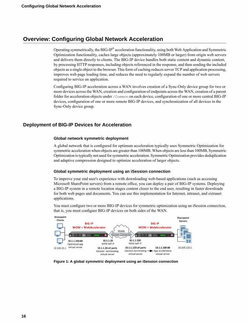
To improve your end user's experience with downloading web-based applications (such as accessingMicrosoft SharePoint servers) from a remote office, you can deploy a pair of BIG-IP systems. Deployinga BIG-IP system in a remote location stages content closer to the end user, resulting in faster downloadsfor both web pages and documents. You can use this implementation for Internet, intranet, and extranetapplications.
You must configure two or more BIG-IP devices for symmetric optimization using an iSession connection,that is, you must configure BIG-IP devices on both sides of the WAN.
Figure 1: A global symmetric deployment using an iSession connection
16
Configuring Global Network Acceleration
About symmetric request and response headers
In a global network that includes a symmetric deployment of remote and central BIG-IP® devices across aWAN, the remote BIG-IP device receives a request and includes an X-Client-WA header, whichdistinguishes the request to the central BIG-IP device, enabling the central BIG-IP device to process therequest, as necessary. When the central BIG-IP device receives a response for the origin web servers, itincludes an X-WA-Surrogate header in the response, which distinguishes the response to the remote BIG-IPdevice, which processes the response as necessary and removes the X-WA-Surrogate header before sendingthe response to the client.
Working with Sync-Only device groups
One of the types of device groups that you can create is a Sync-Only device group. A Sync-Only devicegroup contains devices that synchronize configuration data with one another, but their configuration datadoes not fail over to other members of the device group. A maximum of 32 devices is supported in aSync-Only device group.
A device in a trust domain can be a member of more than one Sync-Only device group. A device can alsobe a member of both a Sync-Failover group and a Sync-Only group.
A typical use of a Sync-Only device group is one in which you configure a device to synchronize the contentsof a specific folder to a different device group than to the device group to which the other folders aresynchronized.
What is device trust?
Before any BIG-IP® devices on a local network can synchronize configuration data or fail over to oneanother, they must establish a trust relationship known as device trust.Device trust between any two BIG-IPdevices on the network is based on mutual authentication through the signing and exchange of x509certificates.
Devices on a local network that trust one another constitute a trust domain. A trust domain is a collectionof BIG-IP devices that trust one another and can therefore synchronize and possibly fail over their BIG-IPconfiguration data, as well as exchange status and failover messages on a regular basis. A local trust domainis a trust domain that includes the local device, that is, the device you are currently logged in to. You cansynchronize a device's configuration data with either all of the devices in the local trust domain, or to asubset of devices in the local trust domain.
Note: You can add devices to a local trust domain from a single device on the network. You can also viewthe identities of all devices in the local trust domain from a single device in the domain. However, to maintainor change the authority of each trust domain member, you must log in locally to each device.
17
BIG-IP® Acceleration: Network Configuration
Illustration of Sync-Only device group configuration
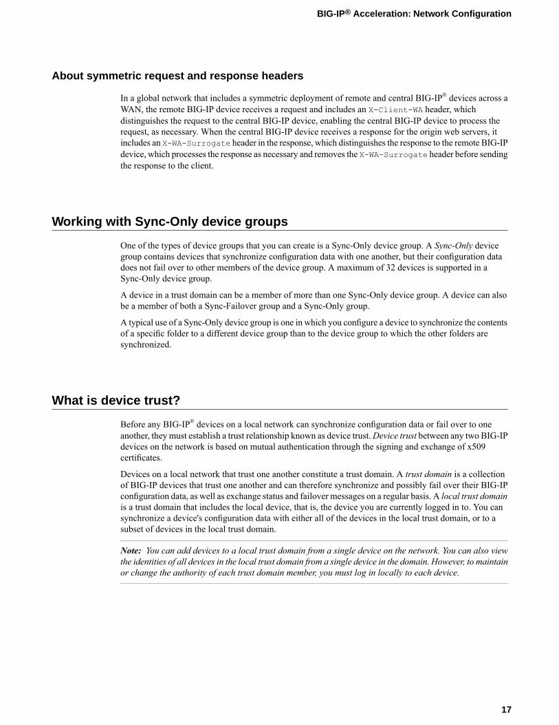
You can use a Sync-Only device group to synchronize policy data in a specific folder across a local trustdomain.
Figure 2: Sync-Only Device Group
Device identity
The devices in a BIG-IP® device group use x509 certificates for mutual authentication. Each device in adevice group has an x509 certificate installed on it that the device uses to authenticate itself to the otherdevices in the group.
Device identity is a set of information that uniquely identifies that device in the device group, for the purposeof authentication. Device identity consists of the x509 certificate, plus this information:
• Device name• Host name• Platform serial number• Platform MAC address• Certificate name• Subjects• Expiration• Certificate serial number• Signature status
Tip: From the Device Trust: Identity screen in the BIG-IP Configuration utility, you can view the x509certificate installed on the local device.
Task summary
Perform these tasks to create a Sync-Only device group.
18
Configuring Global Network Acceleration
Task listDefining an NTP serverAdding a device to the local trust domainCreating a Sync-Only device groupSyncing the BIG-IP configuration to the device group
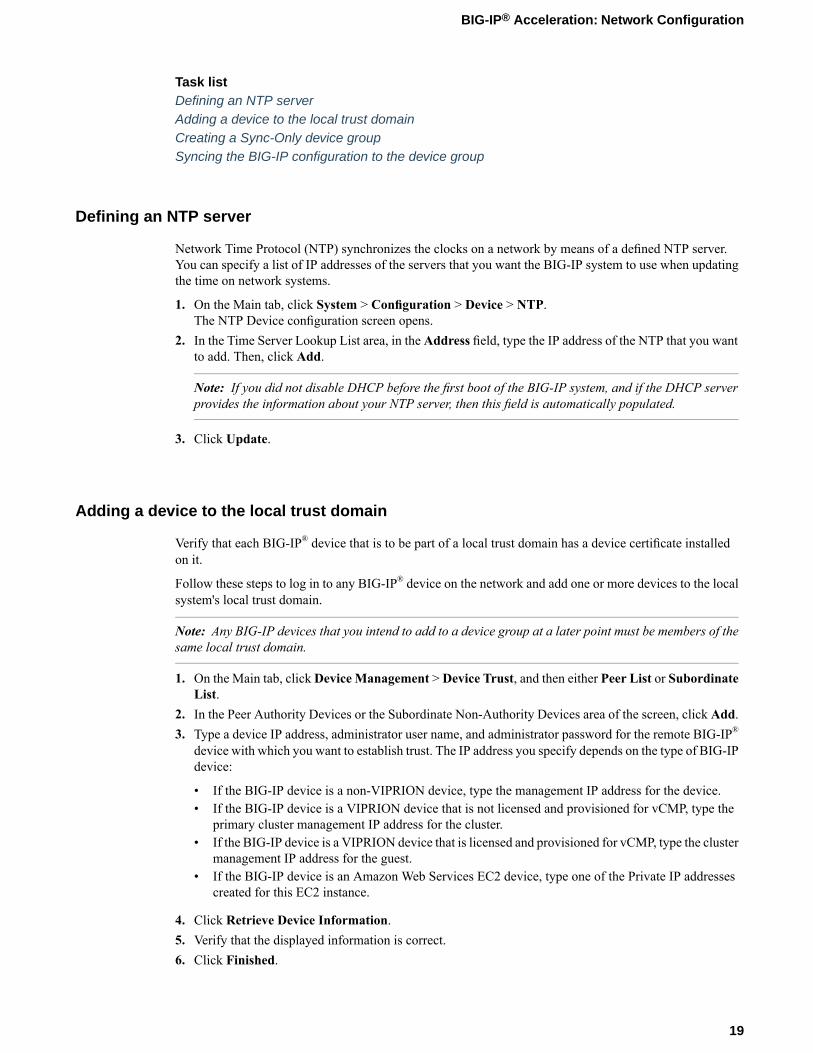
Defining an NTP server
Network Time Protocol (NTP) synchronizes the clocks on a network by means of a defined NTP server.You can specify a list of IP addresses of the servers that you want the BIG-IP system to use when updatingthe time on network systems.
1. On the Main tab, click System > Configuration > Device > NTP.The NTP Device configuration screen opens.
2. In the Time Server Lookup List area, in the Address field, type the IP address of the NTP that you wantto add. Then, click Add.
Note: If you did not disable DHCP before the first boot of the BIG-IP system, and if the DHCP serverprovides the information about your NTP server, then this field is automatically populated.
3. Click Update.
Adding a device to the local trust domain
Verify that each BIG-IP® device that is to be part of a local trust domain has a device certificate installedon it.
Follow these steps to log in to any BIG-IP® device on the network and add one or more devices to the localsystem's local trust domain.
Note: Any BIG-IP devices that you intend to add to a device group at a later point must be members of thesame local trust domain.
1. On the Main tab, clickDevice Management >Device Trust, and then either Peer List or SubordinateList.
2. In the Peer Authority Devices or the Subordinate Non-Authority Devices area of the screen, click Add.3. Type a device IP address, administrator user name, and administrator password for the remote BIG-IP®
device with which you want to establish trust. The IP address you specify depends on the type of BIG-IPdevice:
• If the BIG-IP device is a non-VIPRION device, type the management IP address for the device.• If the BIG-IP device is a VIPRION device that is not licensed and provisioned for vCMP, type the
primary cluster management IP address for the cluster.• If the BIG-IP device is a VIPRION device that is licensed and provisioned for vCMP, type the cluster
management IP address for the guest.• If the BIG-IP device is an Amazon Web Services EC2 device, type one of the Private IP addresses
created for this EC2 instance.
4. Click Retrieve Device Information.5. Verify that the displayed information is correct.6. Click Finished.
19
BIG-IP® Acceleration: Network Configuration
After you perform this task, the local device and the device that you specified in this procedure have a trustrelationship and, therefore, are qualified to join a device group.
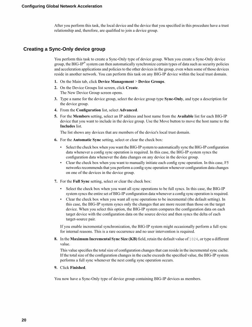
Creating a Sync-Only device group
You perform this task to create a Sync-Only type of device group. When you create a Sync-Only devicegroup, the BIG-IP® system can then automatically synchronize certain types of data such as security policiesand acceleration applications and policies to the other devices in the group, even when some of those devicesreside in another network. You can perform this task on any BIG-IP device within the local trust domain.
1. On the Main tab, click Device Management > Device Groups.2. On the Device Groups list screen, click Create.
The New Device Group screen opens.3. Type a name for the device group, select the device group type Sync-Only, and type a description for
the device group.4. From the Configuration list, select Advanced.5. For theMembers setting, select an IP address and host name from the Available list for each BIG-IP
device that you want to include in the device group. Use the Move button to move the host name to theIncludes list.The list shows any devices that are members of the device's local trust domain.
6. For the Automatic Sync setting, select or clear the check box:
• Select the check boxwhen youwant the BIG-IP system to automatically sync the BIG-IP configurationdata whenever a config sync operation is required. In this case, the BIG-IP system syncs theconfiguration data whenever the data changes on any device in the device group.
• Clear the check box when you want to manually initiate each config sync operation. In this case, F5networks recommends that you perform a config sync operation whenever configuration data changeson one of the devices in the device group.
7. For the Full Sync setting, select or clear the check box:
• Select the check box when you want all sync operations to be full syncs. In this case, the BIG-IPsystem syncs the entire set of BIG-IP configuration data whenever a config sync operation is required.
• Clear the check box when you want all sync operations to be incremental (the default setting). Inthis case, the BIG-IP system syncs only the changes that are more recent than those on the targetdevice. When you select this option, the BIG-IP system compares the configuration data on eachtarget device with the configuration data on the source device and then syncs the delta of eachtarget-source pair.
If you enable incremental synchronization, the BIG-IP system might occasionally perform a full syncfor internal reasons. This is a rare occurrence and no user intervention is required.
8. In theMaximum Incremental Sync Size (KB) field, retain the default value of 1024, or type a differentvalue.This value specifies the total size of configuration changes that can reside in the incremental sync cache.If the total size of the configuration changes in the cache exceeds the specified value, the BIG-IP systemperforms a full sync whenever the next config sync operation occurs.
9. Click Finished.
You now have a Sync-Only type of device group containing BIG-IP devices as members.
20
Configuring Global Network Acceleration
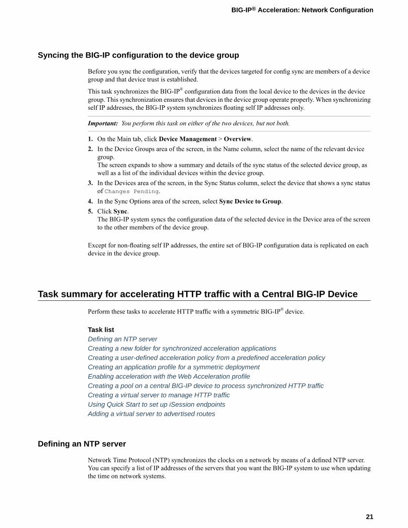
Syncing the BIG-IP configuration to the device group
Before you sync the configuration, verify that the devices targeted for config sync are members of a devicegroup and that device trust is established.
This task synchronizes the BIG-IP® configuration data from the local device to the devices in the devicegroup. This synchronization ensures that devices in the device group operate properly. When synchronizingself IP addresses, the BIG-IP system synchronizes floating self IP addresses only.
Important: You perform this task on either of the two devices, but not both.
1. On the Main tab, click Device Management > Overview.2. In the Device Groups area of the screen, in the Name column, select the name of the relevant device
group.The screen expands to show a summary and details of the sync status of the selected device group, aswell as a list of the individual devices within the device group.
3. In the Devices area of the screen, in the Sync Status column, select the device that shows a sync statusof Changes Pending.
4. In the Sync Options area of the screen, select Sync Device to Group.5. Click Sync.
The BIG-IP system syncs the configuration data of the selected device in the Device area of the screento the other members of the device group.
Except for non-floating self IP addresses, the entire set of BIG-IP configuration data is replicated on eachdevice in the device group.
Task summary for accelerating HTTP traffic with a Central BIG-IP Device
Perform these tasks to accelerate HTTP traffic with a symmetric BIG-IP® device.
Task listDefining an NTP serverCreating a new folder for synchronized acceleration applicationsCreating a user-defined acceleration policy from a predefined acceleration policyCreating an application profile for a symmetric deploymentEnabling acceleration with the Web Acceleration profileCreating a pool on a central BIG-IP device to process synchronized HTTP trafficCreating a virtual server to manage HTTP trafficUsing Quick Start to set up iSession endpointsAdding a virtual server to advertised routes
Defining an NTP server
Network Time Protocol (NTP) synchronizes the clocks on a network by means of a defined NTP server.You can specify a list of IP addresses of the servers that you want the BIG-IP system to use when updatingthe time on network systems.
21
BIG-IP® Acceleration: Network Configuration
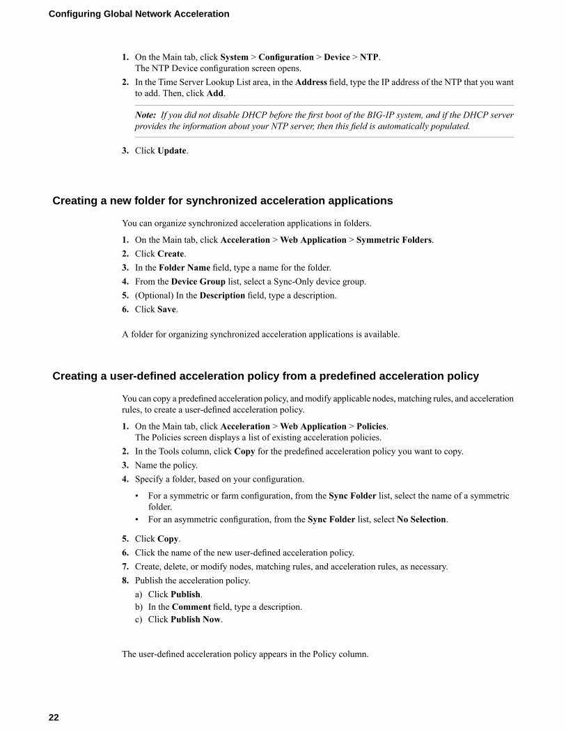
1. On the Main tab, click System > Configuration > Device > NTP.The NTP Device configuration screen opens.
2. In the Time Server Lookup List area, in the Address field, type the IP address of the NTP that you wantto add. Then, click Add.
Note: If you did not disable DHCP before the first boot of the BIG-IP system, and if the DHCP serverprovides the information about your NTP server, then this field is automatically populated.
3. Click Update.
Creating a new folder for synchronized acceleration applications
You can organize synchronized acceleration applications in folders.
1. On the Main tab, click Acceleration >Web Application > Symmetric Folders.2. Click Create.3. In the Folder Name field, type a name for the folder.4. From the Device Group list, select a Sync-Only device group.5. (Optional) In the Description field, type a description.6. Click Save.
A folder for organizing synchronized acceleration applications is available.
Creating a user-defined acceleration policy from a predefined acceleration policy
You can copy a predefined acceleration policy, andmodify applicable nodes, matching rules, and accelerationrules, to create a user-defined acceleration policy.
1. On the Main tab, click Acceleration >Web Application > Policies.The Policies screen displays a list of existing acceleration policies.
2. In the Tools column, click Copy for the predefined acceleration policy you want to copy.3. Name the policy.4. Specify a folder, based on your configuration.
• For a symmetric or farm configuration, from the Sync Folder list, select the name of a symmetricfolder.
• For an asymmetric configuration, from the Sync Folder list, select No Selection.
5. Click Copy.6. Click the name of the new user-defined acceleration policy.7. Create, delete, or modify nodes, matching rules, and acceleration rules, as necessary.8. Publish the acceleration policy.
a) Click Publish.b) In the Comment field, type a description.c) Click Publish Now.
The user-defined acceleration policy appears in the Policy column.
22
Configuring Global Network Acceleration
Creating an application profile for a symmetric deployment
An application profile provides the necessary information to appropriately handle requests to your site'sweb applications.
Important: For symmetric mode, you cannot modify an existing application, because the sync-only folderfor a symmetric configuration becomes unavailable. To use an application in a symmetric deployment, youmust specify the symmetric mode and symmetric sync-only folder when you create the application.
1. On the Main tab, click Acceleration >Web Application > Applications.The Applications List screen opens.
2. Click Create.3. From the General Options list, select Advanced.4. Name the application.5. In the Description field, type a description.6. From the Policy list, select a policy.7. In the Requested Host field, type each domain name (host name), or IP address, that might appear in
HTTP requests for your web application.The specified domain names, or IP addresses, are defined in the host map for the application profile.
8. Configure the Symmetric Deployment settings.a) From the Symmetric Mode list, select Symmetric.
Note: Selecting Symmetric from the Symmetric Mode list enables the BIG-IP to broadcastinvalidations of cached content to all devices within the Sync-Only device group, as well as enablesymmetric processing of traffic.
b) From the Sync Folder list, select a Sync-Only device group.
9. Click Save.
The application profile appears in the Application column on the Applications List screen.
Enabling acceleration with the Web Acceleration profile
A BIG-IP® Acceleration application for aWeb Application must be available.
The Web Acceleration profile enables acceleration by using applications that run on a virtual server.
1. On the Main tab, click Local Traffic > Profiles > Services >Web Acceleration.The Web Acceleration profile list screen opens.
2. Click the name of a profile.3. Select the Custom check box.4. For theWA Applications setting, select an application in the Available list and click Enable.
The application is listed in the Enabled list.5. Click Update.
Acceleration is enabled through the BIG-IP application in the Web Acceleration profile.
23
BIG-IP® Acceleration: Network Configuration
Creating a pool on a central BIG-IP device to process synchronized HTTP traffic
You can create a pool of web servers on a central BIG-IP device to process synchronized HTTP requestsacross a global network.
Note: Skip this task if you forward HTTP traffic to a single server or use a wildcard for the destination.
1. On the Main tab, click Local Traffic > Pools.The Pool List screen opens.
2. Click Create.The New Pool screen opens.
3. In the Name field, type a unique name for the pool.4. For theHealth Monitors setting, from the Available list, select the httpmonitor, and click << to move
the monitor to the Active list.5. From the Load Balancing Method list, select how the system distributes traffic to members of this
pool.The default is Round Robin.
6. For the Priority Group Activation setting, specify how to handle priority groups:
• Select Disabled to disable priority groups. This is the default option.• Select Less than, and in the Available Members field type the minimum number of members that
must remain available in each priority group in order for traffic to remain confined to that group.
7. Using the New Members setting, add each resource that you want to include in the pool:a) Type an IP address in the Address field.b) Type 80 in the Service Port field, or select HTTP from the list.c) (Optional) Type a priority number in the Priority field.d) Click Add.
8. Click Finished.
The new pool appears in the Pools list.
Creating a virtual server to manage HTTP traffic
You can create a virtual server to manage HTTP traffic as either a host virtual server or a network virtualserver.
1. On the Main tab, click Local Traffic > Virtual Servers.The Virtual Server List screen opens.
2. Click the Create button.The New Virtual Server screen opens.
3. In the Name field, type a unique name for the virtual server.4. For the Destination setting, in the Address field, type the IP address you want to use for the virtual
server.The IP address you type must be available and not in the loopback network.
5. In the Service Port field, type 80, or select HTTP from the list.6. From the HTTP Profile list, select http.
24
Configuring Global Network Acceleration
7. From the HTTP Compression Profile list, select one of the following profiles:
• httpcompression• wan-optimized-compression• A customized profile
8. From theWebAcceleration Profile list, select one of the following profiles with an enabled application:
• optimized-acceleration• optimized-caching• webacceleration• A customized profile
9. In the Resources area of the screen, from the Default Pool list, select a pool name.10. Click Finished.
The HTTP virtual server appears in the list of existing virtual servers on the Virtual Server List screen.
Using Quick Start to set up iSession endpoints
You can view the Quick Start screen only after you have defined at least one VLAN and at least one selfIP on a configured BIG-IP® system that is provisioned with Application Acceleration Manager™.
You can use the Quick Start screen to set up the iSession™ endpoints on a BIG-IP system. To optimizeWAN traffic, you must configure the iSession endpoints on the BIG-IP systems on both sides of the WAN.
1. On the Main tab, click Acceleration > Quick Start > Symmetric Properties.2. In theWAN Self IP Address field, type the local endpoint IP address, if it is not already displayed.
This IP address must be in the same subnet as a self IP address on the BIG-IP system, and to make surethat dynamic discovery properly detects this endpoint, the IP address must be the same as a self IPaddress on the BIG-IP system.
3. Verify that the Discovery setting is set to Enabled.If you disable theDiscovery setting, or discovery fails, youmust manually configure any remote endpointsand advertised routes.
4. Specify the VLANs on which the virtual servers on this system receive incoming traffic.DescriptionOption
Select the VLANs that receive incoming LAN traffic destined for theWAN.
LAN VLANs
Select the VLANs that receive traffic from the WAN through aniSession™ connection.
WAN VLANs
5. Click Apply.
You have now established the local endpoint for the iSession connection, and the system automaticallycreated a virtual server on this endpoint for terminating incoming iSession traffic.
To complete the iSession connection, you must also set up the local endpoint on the BIG-IP system on theother side of the WAN. When you set up the other local endpoint, that system creates a virtual server forterminating traffic sent from this BIG-IP system.
25
BIG-IP® Acceleration: Network Configuration
Adding a virtual server to advertised routes
You can add the IP address of a virtual server you created to intercept application traffic to the list ofadvertised iSession™ routes on the central BIG-IP® system. This configuration tells the BIG-IP system inthe remote location that the iSession-terminating endpoint on the central BIG-IP system can route trafficto the application server.
1. On the Main tab, click Acceleration > Symmetric Optimization > Advertised Routes.2. Click Create.
The New Advertised Routes screen opens.3. In the Name field, type a name for a the advertised route (subnet).4. In the Address field, type the IP address of the virtual server you created for accelerating application
traffic.5. In the Netmask field, type 255.255.255.255.6. Click Finished.
The remote BIG-IP system now knows that the iSession-terminating endpoint on the central BIG-IP systemcan route traffic to the application server.
Verify that the iSession profile on the iSession-terminating (endpoint) virtual server is configured to targetthis virtual server. The default profile isession, for which the default Target Virtual setting ismatchall is appropriate, as long as the Address setting for this virtual server is not a wildcard (0.0.0.0).
Task summary for accelerating HTTP traffic with a Remote BIG-IP Device
Perform these tasks to accelerate HTTP traffic with a symmetric BIG-IP® device.
Task listDefining an NTP serverEnabling acceleration with the Web Acceleration profileCreating a virtual server to manage HTTP trafficUsing Quick Start to set up iSession endpointsClearing a Remote BIG-IP Device cache
Defining an NTP server
Network Time Protocol (NTP) synchronizes the clocks on a network by means of a defined NTP server.You can specify a list of IP addresses of the servers that you want the BIG-IP system to use when updatingthe time on network systems.
1. On the Main tab, click System > Configuration > Device > NTP.The NTP Device configuration screen opens.
2. In the Time Server Lookup List area, in the Address field, type the IP address of the NTP that you wantto add. Then, click Add.
Note: If you did not disable DHCP before the first boot of the BIG-IP system, and if the DHCP serverprovides the information about your NTP server, then this field is automatically populated.
26
Configuring Global Network Acceleration

3. Click Update.
Enabling acceleration with the Web Acceleration profile
A BIG-IP® Acceleration application for aWeb Application must be available.
The Web Acceleration profile enables acceleration by using applications that run on a virtual server.
1. On the Main tab, click Local Traffic > Profiles > Services >Web Acceleration.The Web Acceleration profile list screen opens.
2. Click the name of a profile.3. Select the Custom check box.4. For theWA Applications setting, select an application in the Available list and click Enable.
The application is listed in the Enabled list.5. Click Update.
Acceleration is enabled through the BIG-IP application in the Web Acceleration profile.
Creating a virtual server to manage HTTP traffic
You can create a virtual server to manage HTTP traffic as either a host virtual server or a network virtualserver.
1. On the Main tab, click Local Traffic > Virtual Servers.The Virtual Server List screen opens.
2. Click the Create button.The New Virtual Server screen opens.
3. In the Name field, type a unique name for the virtual server.4. For the Destination setting, in the Address field, type the IP address you want to use for the virtual
server.The IP address you type must be available and not in the loopback network.
5. In the Service Port field, type 80, or select HTTP from the list.6. From the HTTP Profile list, select http.7. From the HTTP Compression Profile list, select one of the following profiles:
• httpcompression• wan-optimized-compression• A customized profile
8. From theWebAcceleration Profile list, select one of the following profiles with an enabled application:
• optimized-acceleration• optimized-caching• webacceleration• A customized profile
9. In the Resources area of the screen, from the Default Pool list, select a pool name.10. Click Finished.
The HTTP virtual server appears in the list of existing virtual servers on the Virtual Server List screen.
27
BIG-IP® Acceleration: Network Configuration

Using Quick Start to set up iSession endpoints
You can view the Quick Start screen only after you have defined at least one VLAN and at least one selfIP on a configured BIG-IP® system that is provisioned with Application Acceleration Manager™.
You can use the Quick Start screen to set up the iSession™ endpoints on a BIG-IP system. To optimizeWAN traffic, you must configure the iSession endpoints on the BIG-IP systems on both sides of the WAN.
1. On the Main tab, click Acceleration > Quick Start > Symmetric Properties.2. In theWAN Self IP Address field, type the local endpoint IP address, if it is not already displayed.
This IP address must be in the same subnet as a self IP address on the BIG-IP system, and to make surethat dynamic discovery properly detects this endpoint, the IP address must be the same as a self IPaddress on the BIG-IP system.
3. Verify that the Discovery setting is set to Enabled.If you disable theDiscovery setting, or discovery fails, youmust manually configure any remote endpointsand advertised routes.
4. Specify the VLANs on which the virtual servers on this system receive incoming traffic.DescriptionOption
Select the VLANs that receive incoming LAN traffic destined for theWAN.
LAN VLANs
Select the VLANs that receive traffic from the WAN through aniSession™ connection.
WAN VLANs
5. Click Apply.
You have now established the local endpoint for the iSession connection, and the system automaticallycreated a virtual server on this endpoint for terminating incoming iSession traffic.
To complete the iSession connection, you must also set up the local endpoint on the BIG-IP system on theother side of the WAN. When you set up the other local endpoint, that system creates a virtual server forterminating traffic sent from this BIG-IP system.
Clearing a Remote BIG-IP Device cache
Before you can clear the Acceleration cache on the Remote BIG-IP® Device, the BIG-IP device needs tobe added to the sync-only device group for the symmetric deployment.
After you configure a Remote BIG-IP Device in a symmetric deployment, you can manually clear theAcceleration cache to ensure that the device is serving valid objects.
1. Log on to the command line of the system using the root account.2. Type this command at the command line.
wa_clear_cache
The Remote BIG-IP Device Acceleration cache is clear.
28
Configuring Global Network Acceleration

Implementation results
The central and remote BIG-IP devices are configured symmetrically to accelerate HTTP traffic.
29
BIG-IP® Acceleration: Network Configuration

Chapter
2Configuring Global Network Acceleration for WebApplication
• Overview: Configuring Global NetworkAcceleration for Web Application
• Working with Sync-Only device groups• What is device trust?• Illustration of Sync-Only device group
configuration• Device identity• Task summary• Task summary for accelerating HTTP traffic
with a Central BIG-IP Device• Task summary for accelerating HTTP traffic
with a Remote BIG-IP Device• Implementation results
Overview: Configuring Global Network Acceleration for Web Application
Operating symmetrically, the BIG-IP® acceleration functionality, using Web Application functionality,caches objects from origin web servers (less than approximately 100MB) and delivers them directly toclients. The BIG-IP device handles both static content and dynamic content, by processing HTTP responses,including objects referenced in the response, and then sending the included objects as a single object to thebrowser. This form of caching reduces server TCP and application processing, improves web page loadingtime, and reduces the need to regularly expand the number of web servers required to service an application.
Configuring BIG-IP acceleration across a WAN involves creation of a Sync-Only device group for two ormore devices across the WAN, creation of a parent folder for acceleration objects under /Common on eachdevice, configuration of one or more central BIG-IP devices, configuration of one or more remote BIG-IPdevices, and synchronization of all devices in the Sync-Only device group.
Deployment of BIG-IP Devices for Acceleration
Global network symmetric deployment with an application configured symmetrically
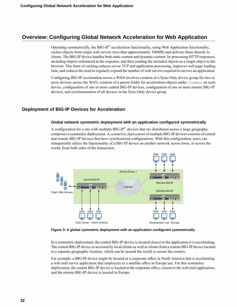
A configuration for a site with multiple BIG-IP® devices that are distributed across a large geographycomprises a symmetric deployment. A symmetric deployment of multiple BIG-IP devices consists of centraland remote BIG-IP devices that have synchronized configurations. With this configuration, users cantransparently utilize the functionality of a BIG-IP device on another network across town, or across theworld, from both sides of the transaction.
Figure 3: A global symmetric deployment with an application configured symmetrically
In a symmetric deployment, the central BIG-IP device is located closest to the application it is accelerating.The central BIG-IP device is accessed by local clients as well as clients from a remote BIG-IP device locatedin a separate geographic location, which can be around the world or across the country.
For example, a BIG-IP device might be located at a corporate office in North America that is acceleratinga web mail server application that employees in a satellite office in Europe use. For this symmetricdeployment, the central BIG-IP device is located at the corporate office, closest to the web mail application,and the remote BIG-IP device is located in Europe.
32
Configuring Global Network Acceleration for Web Application
Once the remote BIG-IP device in Europe receives the response from the central BIG-IP device in NorthAmerica, it caches that response and then sends it to the employee. As long as the content is still valid, theremote BIG-IP device in Europe can then respond to the future requests for the same content from localclients.
Note: To monitor the status of an origin web server in a symmetric deployment, you must do so throughthe BIG-IP Local Traffic Manager™ system's http monitor only on the central BIG-IP device.
About symmetric request and response headers
In a global network that includes a symmetric deployment of remote and central BIG-IP® devices across aWAN, the remote BIG-IP device receives a request and includes an X-Client-WA header, whichdistinguishes the request to the central BIG-IP device, enabling the central BIG-IP device to process therequest, as necessary. When the central BIG-IP device receives a response for the origin web servers, itincludes an X-WA-Surrogate header in the response, which distinguishes the response to the remote BIG-IPdevice, which processes the response as necessary and removes the X-WA-Surrogate header before sendingthe response to the client.
Working with Sync-Only device groups
One of the types of device groups that you can create is a Sync-Only device group. A Sync-Only devicegroup contains devices that synchronize configuration data with one another, but their configuration datadoes not fail over to other members of the device group. A maximum of 32 devices is supported in aSync-Only device group.
A device in a trust domain can be a member of more than one Sync-Only device group. A device can alsobe a member of both a Sync-Failover group and a Sync-Only group.
A typical use of a Sync-Only device group is one in which you configure a device to synchronize the contentsof a specific folder to a different device group than to the device group to which the other folders aresynchronized.
What is device trust?
Before any BIG-IP® devices on a local network can synchronize configuration data or fail over to oneanother, they must establish a trust relationship known as device trust.Device trust between any two BIG-IPdevices on the network is based on mutual authentication through the signing and exchange of x509certificates.
Devices on a local network that trust one another constitute a trust domain. A trust domain is a collectionof BIG-IP devices that trust one another and can therefore synchronize and possibly fail over their BIG-IPconfiguration data, as well as exchange status and failover messages on a regular basis. A local trust domainis a trust domain that includes the local device, that is, the device you are currently logged in to. You cansynchronize a device's configuration data with either all of the devices in the local trust domain, or to asubset of devices in the local trust domain.
33
BIG-IP® Acceleration: Network Configuration
Note: You can add devices to a local trust domain from a single device on the network. You can also viewthe identities of all devices in the local trust domain from a single device in the domain. However, to maintainor change the authority of each trust domain member, you must log in locally to each device.
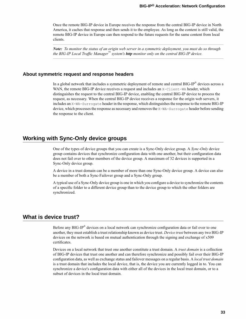
Illustration of Sync-Only device group configuration
You can use a Sync-Only device group to synchronize policy data in a specific folder across a local trustdomain.
Figure 4: Sync-Only Device Group
Device identity
The devices in a BIG-IP® device group use x509 certificates for mutual authentication. Each device in adevice group has an x509 certificate installed on it that the device uses to authenticate itself to the otherdevices in the group.
Device identity is a set of information that uniquely identifies that device in the device group, for the purposeof authentication. Device identity consists of the x509 certificate, plus this information:
• Device name• Host name• Platform serial number• Platform MAC address• Certificate name• Subjects• Expiration• Certificate serial number• Signature status
Tip: From the Device Trust: Identity screen in the BIG-IP Configuration utility, you can view the x509certificate installed on the local device.
34
Configuring Global Network Acceleration for Web Application
Task summary
Perform these tasks to create a Sync-Only device group.
Task listDefining an NTP serverAdding a device to the local trust domainCreating a Sync-Only device groupSyncing the BIG-IP configuration to the device group
Defining an NTP server
Network Time Protocol (NTP) synchronizes the clocks on a network by means of a defined NTP server.You can specify a list of IP addresses of the servers that you want the BIG-IP system to use when updatingthe time on network systems.
1. On the Main tab, click System > Configuration > Device > NTP.The NTP Device configuration screen opens.
2. In the Time Server Lookup List area, in the Address field, type the IP address of the NTP that you wantto add. Then, click Add.
Note: If you did not disable DHCP before the first boot of the BIG-IP system, and if the DHCP serverprovides the information about your NTP server, then this field is automatically populated.
3. Click Update.
Adding a device to the local trust domain
Verify that each BIG-IP® device that is to be part of a local trust domain has a device certificate installedon it.
Follow these steps to log in to any BIG-IP® device on the network and add one or more devices to the localsystem's local trust domain.
Note: Any BIG-IP devices that you intend to add to a device group at a later point must be members of thesame local trust domain.
1. On the Main tab, clickDevice Management >Device Trust, and then either Peer List or SubordinateList.
2. In the Peer Authority Devices or the Subordinate Non-Authority Devices area of the screen, click Add.3. Type a device IP address, administrator user name, and administrator password for the remote BIG-IP®
device with which you want to establish trust. The IP address you specify depends on the type of BIG-IPdevice:
• If the BIG-IP device is a non-VIPRION device, type the management IP address for the device.• If the BIG-IP device is a VIPRION device that is not licensed and provisioned for vCMP, type the
primary cluster management IP address for the cluster.
35
BIG-IP® Acceleration: Network Configuration

• If the BIG-IP device is a VIPRION device that is licensed and provisioned for vCMP, type the clustermanagement IP address for the guest.
• If the BIG-IP device is an Amazon Web Services EC2 device, type one of the Private IP addressescreated for this EC2 instance.
4. Click Retrieve Device Information.5. Verify that the displayed information is correct.6. Click Finished.
After you perform this task, the local device and the device that you specified in this procedure have a trustrelationship and, therefore, are qualified to join a device group.
Creating a Sync-Only device group
You perform this task to create a Sync-Only type of device group. When you create a Sync-Only devicegroup, the BIG-IP® system can then automatically synchronize certain types of data such as security policiesand acceleration applications and policies to the other devices in the group, even when some of those devicesreside in another network. You can perform this task on any BIG-IP device within the local trust domain.
1. On the Main tab, click Device Management > Device Groups.2. On the Device Groups list screen, click Create.
The New Device Group screen opens.3. Type a name for the device group, select the device group type Sync-Only, and type a description for
the device group.4. From the Configuration list, select Advanced.5. For theMembers setting, select an IP address and host name from the Available list for each BIG-IP
device that you want to include in the device group. Use the Move button to move the host name to theIncludes list.The list shows any devices that are members of the device's local trust domain.
6. For the Automatic Sync setting, select or clear the check box:
• Select the check boxwhen youwant the BIG-IP system to automatically sync the BIG-IP configurationdata whenever a config sync operation is required. In this case, the BIG-IP system syncs theconfiguration data whenever the data changes on any device in the device group.
• Clear the check box when you want to manually initiate each config sync operation. In this case, F5networks recommends that you perform a config sync operation whenever configuration data changeson one of the devices in the device group.
7. For the Full Sync setting, select or clear the check box:
• Select the check box when you want all sync operations to be full syncs. In this case, the BIG-IPsystem syncs the entire set of BIG-IP configuration data whenever a config sync operation is required.
• Clear the check box when you want all sync operations to be incremental (the default setting). Inthis case, the BIG-IP system syncs only the changes that are more recent than those on the targetdevice. When you select this option, the BIG-IP system compares the configuration data on eachtarget device with the configuration data on the source device and then syncs the delta of eachtarget-source pair.
If you enable incremental synchronization, the BIG-IP system might occasionally perform a full syncfor internal reasons. This is a rare occurrence and no user intervention is required.
8. In theMaximum Incremental Sync Size (KB) field, retain the default value of 1024, or type a differentvalue.
36
Configuring Global Network Acceleration for Web Application
This value specifies the total size of configuration changes that can reside in the incremental sync cache.If the total size of the configuration changes in the cache exceeds the specified value, the BIG-IP systemperforms a full sync whenever the next config sync operation occurs.
9. Click Finished.
You now have a Sync-Only type of device group containing BIG-IP devices as members.
Syncing the BIG-IP configuration to the device group
Before you sync the configuration, verify that the devices targeted for config sync are members of a devicegroup and that device trust is established.
This task synchronizes the BIG-IP® configuration data from the local device to the devices in the devicegroup. This synchronization ensures that devices in the device group operate properly. When synchronizingself IP addresses, the BIG-IP system synchronizes floating self IP addresses only.
Important: You perform this task on either of the two devices, but not both.
1. On the Main tab, click Device Management > Overview.2. In the Device Groups area of the screen, in the Name column, select the name of the relevant device
group.The screen expands to show a summary and details of the sync status of the selected device group, aswell as a list of the individual devices within the device group.
3. In the Devices area of the screen, in the Sync Status column, select the device that shows a sync statusof Changes Pending.
4. In the Sync Options area of the screen, select Sync Device to Group.5. Click Sync.
The BIG-IP system syncs the configuration data of the selected device in the Device area of the screento the other members of the device group.
Except for non-floating self IP addresses, the entire set of BIG-IP configuration data is replicated on eachdevice in the device group.
Task summary for accelerating HTTP traffic with a Central BIG-IP Device
Perform these tasks to accelerate HTTP traffic with a symmetric BIG-IP® device.
Task listDefining an NTP serverCreating a new folder for synchronized acceleration applicationsCreating a user-defined acceleration policy from a predefined acceleration policyCreating an application profile for a symmetric deploymentEnabling acceleration with the Web Acceleration profileCreating a pool on a central BIG-IP device to process synchronized HTTP trafficCreating a virtual server to manage HTTP traffic
37
BIG-IP® Acceleration: Network Configuration
Defining an NTP server
Network Time Protocol (NTP) synchronizes the clocks on a network by means of a defined NTP server.You can specify a list of IP addresses of the servers that you want the BIG-IP system to use when updatingthe time on network systems.
1. On the Main tab, click System > Configuration > Device > NTP.The NTP Device configuration screen opens.
2. In the Time Server Lookup List area, in the Address field, type the IP address of the NTP that you wantto add. Then, click Add.
Note: If you did not disable DHCP before the first boot of the BIG-IP system, and if the DHCP serverprovides the information about your NTP server, then this field is automatically populated.
3. Click Update.
Creating a new folder for synchronized acceleration applications
You can organize synchronized acceleration applications in folders.
1. On the Main tab, click Acceleration >Web Application > Symmetric Folders.2. Click Create.3. In the Folder Name field, type a name for the folder.4. From the Device Group list, select a Sync-Only device group.5. (Optional) In the Description field, type a description.6. Click Save.
A folder for organizing synchronized acceleration applications is available.
Creating a user-defined acceleration policy from a predefined acceleration policy
You can copy a predefined acceleration policy, andmodify applicable nodes, matching rules, and accelerationrules, to create a user-defined acceleration policy.
1. On the Main tab, click Acceleration >Web Application > Policies.The Policies screen displays a list of existing acceleration policies.
2. In the Tools column, click Copy for the predefined acceleration policy you want to copy.3. Name the policy.4. Specify a folder, based on your configuration.
• For a symmetric or farm configuration, from the Sync Folder list, select the name of a symmetricfolder.
• For an asymmetric configuration, from the Sync Folder list, select No Selection.
5. Click Copy.6. Click the name of the new user-defined acceleration policy.7. Create, delete, or modify nodes, matching rules, and acceleration rules, as necessary.8. Publish the acceleration policy.
38
Configuring Global Network Acceleration for Web Application
a) Click Publish.b) In the Comment field, type a description.c) Click Publish Now.
The user-defined acceleration policy appears in the Policy column.
Creating an application profile for a symmetric deployment
An application profile provides the necessary information to appropriately handle requests to your site'sweb applications.
Important: For symmetric mode, you cannot modify an existing application, because the sync-only folderfor a symmetric configuration becomes unavailable. To use an application in a symmetric deployment, youmust specify the symmetric mode and symmetric sync-only folder when you create the application.
1. On the Main tab, click Acceleration >Web Application > Applications.The Applications List screen opens.
2. Click Create.3. From the General Options list, select Advanced.4. Name the application.5. In the Description field, type a description.6. From the Policy list, select a policy.7. In the Requested Host field, type each domain name (host name), or IP address, that might appear in
HTTP requests for your web application.The specified domain names, or IP addresses, are defined in the host map for the application profile.
8. Configure the Symmetric Deployment settings.a) From the Symmetric Mode list, select Symmetric.
Note: Selecting Symmetric from the Symmetric Mode list enables the BIG-IP to broadcastinvalidations of cached content to all devices within the Sync-Only device group, as well as enablesymmetric processing of traffic.
b) From the Sync Folder list, select a Sync-Only device group.
9. Click Save.
The application profile appears in the Application column on the Applications List screen.
Enabling acceleration with the Web Acceleration profile
A BIG-IP® Acceleration application for aWeb Application must be available.
The Web Acceleration profile enables acceleration by using applications that run on a virtual server.
1. On the Main tab, click Local Traffic > Profiles > Services >Web Acceleration.The Web Acceleration profile list screen opens.
2. Click the name of a profile.3. Select the Custom check box.4. For theWA Applications setting, select an application in the Available list and click Enable.
39
BIG-IP® Acceleration: Network Configuration

The application is listed in the Enabled list.5. Click Update.
Acceleration is enabled through the BIG-IP application in the Web Acceleration profile.
Creating a pool on a central BIG-IP device to process synchronized HTTP traffic
You can create a pool of web servers on a central BIG-IP device to process synchronized HTTP requestsacross a global network.
Note: Skip this task if you forward HTTP traffic to a single server or use a wildcard for the destination.
1. On the Main tab, click Local Traffic > Pools.The Pool List screen opens.
2. Click Create.The New Pool screen opens.
3. In the Name field, type a unique name for the pool.4. For theHealth Monitors setting, from the Available list, select the httpmonitor, and click << to move
the monitor to the Active list.5. From the Load Balancing Method list, select how the system distributes traffic to members of this
pool.The default is Round Robin.
6. For the Priority Group Activation setting, specify how to handle priority groups:
• Select Disabled to disable priority groups. This is the default option.• Select Less than, and in the Available Members field type the minimum number of members that
must remain available in each priority group in order for traffic to remain confined to that group.
7. Using the New Members setting, add each resource that you want to include in the pool:a) Type an IP address in the Address field.b) Type 80 in the Service Port field, or select HTTP from the list.c) (Optional) Type a priority number in the Priority field.d) Click Add.
8. Click Finished.
The new pool appears in the Pools list.
Creating a virtual server to manage HTTP traffic
You can create a virtual server to manage HTTP traffic as either a host virtual server or a network virtualserver.
1. On the Main tab, click Local Traffic > Virtual Servers.The Virtual Server List screen opens.
2. Click the Create button.The New Virtual Server screen opens.
3. In the Name field, type a unique name for the virtual server.
40
Configuring Global Network Acceleration for Web Application

4. For the Destination setting, in the Address field, type the IP address you want to use for the virtualserver.The IP address you type must be available and not in the loopback network.
5. In the Service Port field, type 80, or select HTTP from the list.6. From the HTTP Profile list, select http.7. From the HTTP Compression Profile list, select one of the following profiles:
• httpcompression• wan-optimized-compression• A customized profile
8. From theWebAcceleration Profile list, select one of the following profiles with an enabled application:
• optimized-acceleration• optimized-caching• webacceleration• A customized profile
9. In the Resources area of the screen, from the Default Pool list, select a pool name.10. Click Finished.
The HTTP virtual server appears in the list of existing virtual servers on the Virtual Server List screen.
Task summary for accelerating HTTP traffic with a Remote BIG-IP Device
Perform these tasks to accelerate HTTP traffic with a symmetric BIG-IP® device.
Task listDefining an NTP serverEnabling acceleration with the Web Acceleration profileCreating a virtual server to manage HTTP trafficClearing a Remote BIG-IP Device cache
Defining an NTP server
Network Time Protocol (NTP) synchronizes the clocks on a network by means of a defined NTP server.You can specify a list of IP addresses of the servers that you want the BIG-IP system to use when updatingthe time on network systems.
1. On the Main tab, click System > Configuration > Device > NTP.The NTP Device configuration screen opens.
2. In the Time Server Lookup List area, in the Address field, type the IP address of the NTP that you wantto add. Then, click Add.
Note: If you did not disable DHCP before the first boot of the BIG-IP system, and if the DHCP serverprovides the information about your NTP server, then this field is automatically populated.
3. Click Update.
41
BIG-IP® Acceleration: Network Configuration
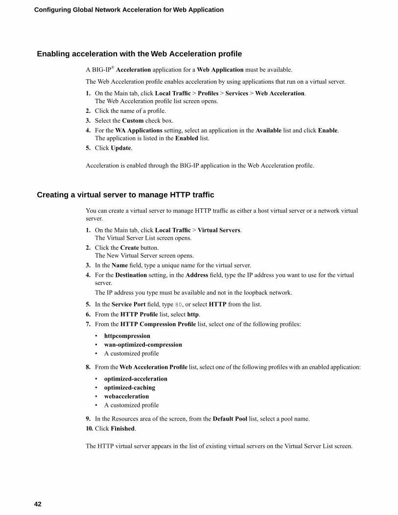
Enabling acceleration with the Web Acceleration profile
A BIG-IP® Acceleration application for aWeb Application must be available.
The Web Acceleration profile enables acceleration by using applications that run on a virtual server.
1. On the Main tab, click Local Traffic > Profiles > Services >Web Acceleration.The Web Acceleration profile list screen opens.
2. Click the name of a profile.3. Select the Custom check box.4. For theWA Applications setting, select an application in the Available list and click Enable.
The application is listed in the Enabled list.5. Click Update.
Acceleration is enabled through the BIG-IP application in the Web Acceleration profile.
Creating a virtual server to manage HTTP traffic
You can create a virtual server to manage HTTP traffic as either a host virtual server or a network virtualserver.
1. On the Main tab, click Local Traffic > Virtual Servers.The Virtual Server List screen opens.
2. Click the Create button.The New Virtual Server screen opens.
3. In the Name field, type a unique name for the virtual server.4. For the Destination setting, in the Address field, type the IP address you want to use for the virtual
server.The IP address you type must be available and not in the loopback network.
5. In the Service Port field, type 80, or select HTTP from the list.6. From the HTTP Profile list, select http.7. From the HTTP Compression Profile list, select one of the following profiles:
• httpcompression• wan-optimized-compression• A customized profile
8. From theWebAcceleration Profile list, select one of the following profiles with an enabled application:
• optimized-acceleration• optimized-caching• webacceleration• A customized profile
9. In the Resources area of the screen, from the Default Pool list, select a pool name.10. Click Finished.
The HTTP virtual server appears in the list of existing virtual servers on the Virtual Server List screen.
42
Configuring Global Network Acceleration for Web Application
Clearing a Remote BIG-IP Device cache
Before you can clear the Acceleration cache on the Remote BIG-IP® Device, the BIG-IP device needs tobe added to the sync-only device group for the symmetric deployment.
After you configure a Remote BIG-IP Device in a symmetric deployment, you can manually clear theAcceleration cache to ensure that the device is serving valid objects.
1. Log on to the command line of the system using the root account.2. Type this command at the command line.
wa_clear_cache
The Remote BIG-IP Device Acceleration cache is clear.
Implementation results
The central and remote BIG-IP devices are configured symmetrically to accelerate HTTP traffic.
43
BIG-IP® Acceleration: Network Configuration

Chapter
3Configuring Acceleration for a Server Farm
• Overview: Configuring Acceleration for aServer Farm
• Working with Sync-Only device groups• What is device trust?• Illustration of Sync-Only device group
configuration• Device identity• Task summary• Task summary for configuring Acceleration
for a Server Farm• Implementation results
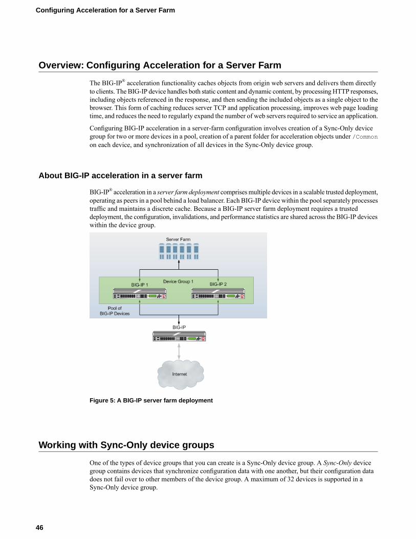
Overview: Configuring Acceleration for a Server Farm
The BIG-IP® acceleration functionality caches objects from origin web servers and delivers them directlyto clients. The BIG-IP device handles both static content and dynamic content, by processingHTTP responses,including objects referenced in the response, and then sending the included objects as a single object to thebrowser. This form of caching reduces server TCP and application processing, improves web page loadingtime, and reduces the need to regularly expand the number of web servers required to service an application.
Configuring BIG-IP acceleration in a server-farm configuration involves creation of a Sync-Only devicegroup for two or more devices in a pool, creation of a parent folder for acceleration objects under /Commonon each device, and synchronization of all devices in the Sync-Only device group.
About BIG-IP acceleration in a server farm
BIG-IP® acceleration in a server farm deployment comprisesmultiple devices in a scalable trusted deployment,operating as peers in a pool behind a load balancer. Each BIG-IP device within the pool separately processestraffic and maintains a discrete cache. Because a BIG-IP server farm deployment requires a trusteddeployment, the configuration, invalidations, and performance statistics are shared across the BIG-IP deviceswithin the device group.
Figure 5: A BIG-IP server farm deployment
Working with Sync-Only device groups
One of the types of device groups that you can create is a Sync-Only device group. A Sync-Only devicegroup contains devices that synchronize configuration data with one another, but their configuration datadoes not fail over to other members of the device group. A maximum of 32 devices is supported in aSync-Only device group.
46
Configuring Acceleration for a Server Farm
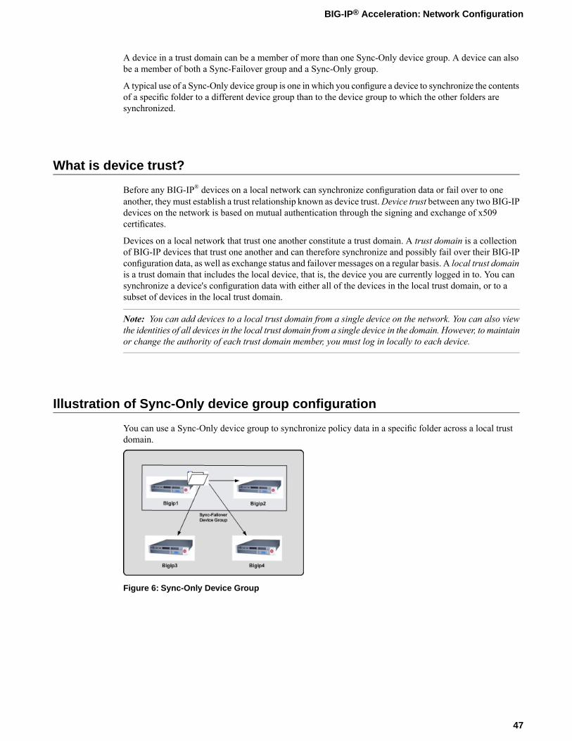
A device in a trust domain can be a member of more than one Sync-Only device group. A device can alsobe a member of both a Sync-Failover group and a Sync-Only group.
A typical use of a Sync-Only device group is one in which you configure a device to synchronize the contentsof a specific folder to a different device group than to the device group to which the other folders aresynchronized.
What is device trust?
Before any BIG-IP® devices on a local network can synchronize configuration data or fail over to oneanother, they must establish a trust relationship known as device trust.Device trust between any two BIG-IPdevices on the network is based on mutual authentication through the signing and exchange of x509certificates.
Devices on a local network that trust one another constitute a trust domain. A trust domain is a collectionof BIG-IP devices that trust one another and can therefore synchronize and possibly fail over their BIG-IPconfiguration data, as well as exchange status and failover messages on a regular basis. A local trust domainis a trust domain that includes the local device, that is, the device you are currently logged in to. You cansynchronize a device's configuration data with either all of the devices in the local trust domain, or to asubset of devices in the local trust domain.
Note: You can add devices to a local trust domain from a single device on the network. You can also viewthe identities of all devices in the local trust domain from a single device in the domain. However, to maintainor change the authority of each trust domain member, you must log in locally to each device.
Illustration of Sync-Only device group configuration
You can use a Sync-Only device group to synchronize policy data in a specific folder across a local trustdomain.
Figure 6: Sync-Only Device Group
47
BIG-IP® Acceleration: Network Configuration
Device identity
The devices in a BIG-IP® device group use x509 certificates for mutual authentication. Each device in adevice group has an x509 certificate installed on it that the device uses to authenticate itself to the otherdevices in the group.
Device identity is a set of information that uniquely identifies that device in the device group, for the purposeof authentication. Device identity consists of the x509 certificate, plus this information:
• Device name• Host name• Platform serial number• Platform MAC address• Certificate name• Subjects• Expiration• Certificate serial number• Signature status
Tip: From the Device Trust: Identity screen in the BIG-IP Configuration utility, you can view the x509certificate installed on the local device.
Task summary
Perform these tasks to create a Sync-Only device group.
Task listDefining an NTP serverAdding a device to the local trust domainCreating a Sync-Only device groupSyncing the BIG-IP configuration to the device group
Defining an NTP server
Network Time Protocol (NTP) synchronizes the clocks on a network by means of a defined NTP server.You can specify a list of IP addresses of the servers that you want the BIG-IP system to use when updatingthe time on network systems.
1. On the Main tab, click System > Configuration > Device > NTP.The NTP Device configuration screen opens.
2. In the Time Server Lookup List area, in the Address field, type the IP address of the NTP that you wantto add. Then, click Add.
Note: If you did not disable DHCP before the first boot of the BIG-IP system, and if the DHCP serverprovides the information about your NTP server, then this field is automatically populated.
48
Configuring Acceleration for a Server Farm
3. Click Update.
Adding a device to the local trust domain
Verify that each BIG-IP® device that is to be part of a local trust domain has a device certificate installedon it.
Follow these steps to log in to any BIG-IP® device on the network and add one or more devices to the localsystem's local trust domain.
Note: Any BIG-IP devices that you intend to add to a device group at a later point must be members of thesame local trust domain.
1. On the Main tab, clickDevice Management >Device Trust, and then either Peer List or SubordinateList.
2. In the Peer Authority Devices or the Subordinate Non-Authority Devices area of the screen, click Add.3. Type a device IP address, administrator user name, and administrator password for the remote BIG-IP®
device with which you want to establish trust. The IP address you specify depends on the type of BIG-IPdevice:
• If the BIG-IP device is a non-VIPRION device, type the management IP address for the device.• If the BIG-IP device is a VIPRION device that is not licensed and provisioned for vCMP, type the
primary cluster management IP address for the cluster.• If the BIG-IP device is a VIPRION device that is licensed and provisioned for vCMP, type the cluster
management IP address for the guest.• If the BIG-IP device is an Amazon Web Services EC2 device, type one of the Private IP addresses
created for this EC2 instance.
4. Click Retrieve Device Information.5. Verify that the displayed information is correct.6. Click Finished.
After you perform this task, the local device and the device that you specified in this procedure have a trustrelationship and, therefore, are qualified to join a device group.
Creating a Sync-Only device group
You perform this task to create a Sync-Only type of device group. When you create a Sync-Only devicegroup, the BIG-IP® system can then automatically synchronize certain types of data such as security policiesand acceleration applications and policies to the other devices in the group, even when some of those devicesreside in another network. You can perform this task on any BIG-IP device within the local trust domain.
1. On the Main tab, click Device Management > Device Groups.2. On the Device Groups list screen, click Create.
The New Device Group screen opens.3. Type a name for the device group, select the device group type Sync-Only, and type a description for
the device group.4. From the Configuration list, select Advanced.
49
BIG-IP® Acceleration: Network Configuration
5. For theMembers setting, select an IP address and host name from the Available list for each BIG-IPdevice that you want to include in the device group. Use the Move button to move the host name to theIncludes list.The list shows any devices that are members of the device's local trust domain.
6. For the Automatic Sync setting, select or clear the check box:
• Select the check boxwhen youwant the BIG-IP system to automatically sync the BIG-IP configurationdata whenever a config sync operation is required. In this case, the BIG-IP system syncs theconfiguration data whenever the data changes on any device in the device group.
• Clear the check box when you want to manually initiate each config sync operation. In this case, F5networks recommends that you perform a config sync operation whenever configuration data changeson one of the devices in the device group.
7. For the Full Sync setting, select or clear the check box:
• Select the check box when you want all sync operations to be full syncs. In this case, the BIG-IPsystem syncs the entire set of BIG-IP configuration data whenever a config sync operation is required.
• Clear the check box when you want all sync operations to be incremental (the default setting). Inthis case, the BIG-IP system syncs only the changes that are more recent than those on the targetdevice. When you select this option, the BIG-IP system compares the configuration data on eachtarget device with the configuration data on the source device and then syncs the delta of eachtarget-source pair.
If you enable incremental synchronization, the BIG-IP system might occasionally perform a full syncfor internal reasons. This is a rare occurrence and no user intervention is required.
8. In theMaximum Incremental Sync Size (KB) field, retain the default value of 1024, or type a differentvalue.This value specifies the total size of configuration changes that can reside in the incremental sync cache.If the total size of the configuration changes in the cache exceeds the specified value, the BIG-IP systemperforms a full sync whenever the next config sync operation occurs.
9. Click Finished.
You now have a Sync-Only type of device group containing BIG-IP devices as members.
Syncing the BIG-IP configuration to the device group
Before you sync the configuration, verify that the devices targeted for config sync are members of a devicegroup and that device trust is established.
This task synchronizes the BIG-IP® configuration data from the local device to the devices in the devicegroup. This synchronization ensures that devices in the device group operate properly. When synchronizingself IP addresses, the BIG-IP system synchronizes floating self IP addresses only.
Important: You perform this task on either of the two devices, but not both.
1. On the Main tab, click Device Management > Overview.2. In the Device Groups area of the screen, in the Name column, select the name of the relevant device
group.The screen expands to show a summary and details of the sync status of the selected device group, aswell as a list of the individual devices within the device group.
3. In the Devices area of the screen, in the Sync Status column, select the device that shows a sync statusof Changes Pending.
4. In the Sync Options area of the screen, select Sync Device to Group.
50
Configuring Acceleration for a Server Farm
5. Click Sync.The BIG-IP system syncs the configuration data of the selected device in the Device area of the screento the other members of the device group.
Except for non-floating self IP addresses, the entire set of BIG-IP configuration data is replicated on eachdevice in the device group.
Task summary for configuring Acceleration for a Server Farm
Perform these tasks to accelerate HTTP traffic in a server farm.
Task listDefining an NTP serverCreating a new folder for synchronized acceleration applicationsCreating a user-defined acceleration policy from a predefined acceleration policyCreating an application profile for a server farm deploymentEnabling acceleration with the Web Acceleration profileCreating a pool on a central BIG-IP device to process synchronized HTTP trafficCreating a virtual server to manage HTTP traffic
Defining an NTP server
Network Time Protocol (NTP) synchronizes the clocks on a network by means of a defined NTP server.You can specify a list of IP addresses of the servers that you want the BIG-IP system to use when updatingthe time on network systems.
1. On the Main tab, click System > Configuration > Device > NTP.The NTP Device configuration screen opens.
2. In the Time Server Lookup List area, in the Address field, type the IP address of the NTP that you wantto add. Then, click Add.
Note: If you did not disable DHCP before the first boot of the BIG-IP system, and if the DHCP serverprovides the information about your NTP server, then this field is automatically populated.
3. Click Update.
Creating a new folder for synchronized acceleration applications
You can organize synchronized acceleration applications in folders.
1. On the Main tab, click Acceleration >Web Application > Symmetric Folders.2. Click Create.3. In the Folder Name field, type a name for the folder.4. From the Device Group list, select a Sync-Only device group.5. (Optional) In the Description field, type a description.6. Click Save.
51
BIG-IP® Acceleration: Network Configuration
A folder for organizing synchronized acceleration applications is available.
Creating a user-defined acceleration policy from a predefined acceleration policy
You can copy a predefined acceleration policy, andmodify applicable nodes, matching rules, and accelerationrules, to create a user-defined acceleration policy.
1. On the Main tab, click Acceleration >Web Application > Policies.The Policies screen displays a list of existing acceleration policies.
2. In the Tools column, click Copy for the predefined acceleration policy you want to copy.3. Name the policy.4. Specify a folder, based on your configuration.
• For a symmetric or farm configuration, from the Sync Folder list, select the name of a symmetricfolder.
• For an asymmetric configuration, from the Sync Folder list, select No Selection.
5. Click Copy.6. Click the name of the new user-defined acceleration policy.7. Create, delete, or modify nodes, matching rules, and acceleration rules, as necessary.8. Publish the acceleration policy.
a) Click Publish.b) In the Comment field, type a description.c) Click Publish Now.
The user-defined acceleration policy appears in the Policy column.
Creating an application profile for a server farm deployment
An application profile provides the necessary information to appropriately handle requests to your site'sweb applications.
1. On the Main tab, click Acceleration >Web Application > Applications.The Applications List screen opens.
2. Click Create.3. From the General Options list, select Advanced.4. Name the application.5. In the Description field, type a description.6. From the Policy list, select a policy.7. In the Requested Host field, type each domain name (host name), or IP address, that might appear in
HTTP requests for your web application.The specified domain names, or IP addresses, are defined in the host map for the application profile.
8. Configure the Symmetric Deployment settings.a) From the Symmetric Mode list, select Farm.
Note: Selecting Farm from the Symmetric Mode list enables the BIG-IP to broadcast invalidationsof cached content to all devices within the Sync-Only device group.
52
Configuring Acceleration for a Server Farm
b) From the Sync Folder list, select a Sync-Only device group.
9. Click Save.
The application profile is created.
Enabling acceleration with the Web Acceleration profile
A BIG-IP® Acceleration application for aWeb Application must be available.
The Web Acceleration profile enables acceleration by using applications that run on a virtual server.
1. On the Main tab, click Local Traffic > Profiles > Services >Web Acceleration.The Web Acceleration profile list screen opens.
2. Click the name of a profile.3. Select the Custom check box.4. For theWA Applications setting, select an application in the Available list and click Enable.
The application is listed in the Enabled list.5. Click Update.
Acceleration is enabled through the BIG-IP application in the Web Acceleration profile.
Creating a pool on a central BIG-IP device to process synchronized HTTP traffic
You can create a pool of web servers on a central BIG-IP device to process synchronized HTTP requestsacross a global network.
Note: Skip this task if you forward HTTP traffic to a single server or use a wildcard for the destination.
1. On the Main tab, click Local Traffic > Pools.The Pool List screen opens.
2. Click Create.The New Pool screen opens.
3. In the Name field, type a unique name for the pool.4. For theHealth Monitors setting, from the Available list, select the httpmonitor, and click << to move
the monitor to the Active list.5. From the Load Balancing Method list, select how the system distributes traffic to members of this
pool.The default is Round Robin.
6. For the Priority Group Activation setting, specify how to handle priority groups:
• Select Disabled to disable priority groups. This is the default option.• Select Less than, and in the Available Members field type the minimum number of members that
must remain available in each priority group in order for traffic to remain confined to that group.
7. Using the New Members setting, add each resource that you want to include in the pool:a) Type an IP address in the Address field.b) Type 80 in the Service Port field, or select HTTP from the list.c) (Optional) Type a priority number in the Priority field.
53
BIG-IP® Acceleration: Network Configuration
d) Click Add.
8. Click Finished.
The new pool appears in the Pools list.
Creating a virtual server to manage HTTP traffic
You can create a virtual server to manage HTTP traffic as either a host virtual server or a network virtualserver.
1. On the Main tab, click Local Traffic > Virtual Servers.The Virtual Server List screen opens.
2. Click the Create button.The New Virtual Server screen opens.
3. In the Name field, type a unique name for the virtual server.4. For the Destination setting, in the Address field, type the IP address you want to use for the virtual
server.The IP address you type must be available and not in the loopback network.
5. In the Service Port field, type 80, or select HTTP from the list.6. From the HTTP Profile list, select http.7. From the HTTP Compression Profile list, select one of the following profiles:
• httpcompression• wan-optimized-compression• A customized profile
8. From theWebAcceleration Profile list, select one of the following profiles with an enabled application:
• optimized-acceleration• optimized-caching• webacceleration• A customized profile
9. In the Resources area of the screen, from the Default Pool list, select a pool name.10. Click Finished.
The HTTP virtual server appears in the list of existing virtual servers on the Virtual Server List screen.
Implementation results
The BIG-IP devices are configured to accelerate HTTP traffic in a server farm.
54
Configuring Acceleration for a Server Farm

Chapter
4Configuring Acceleration with an Asymmetric BIG-IP System
• About an asymmetric BIG-IP deployment• Task summary for configuring Acceleration
with an asymmetric BIG-IP system• Implementation result
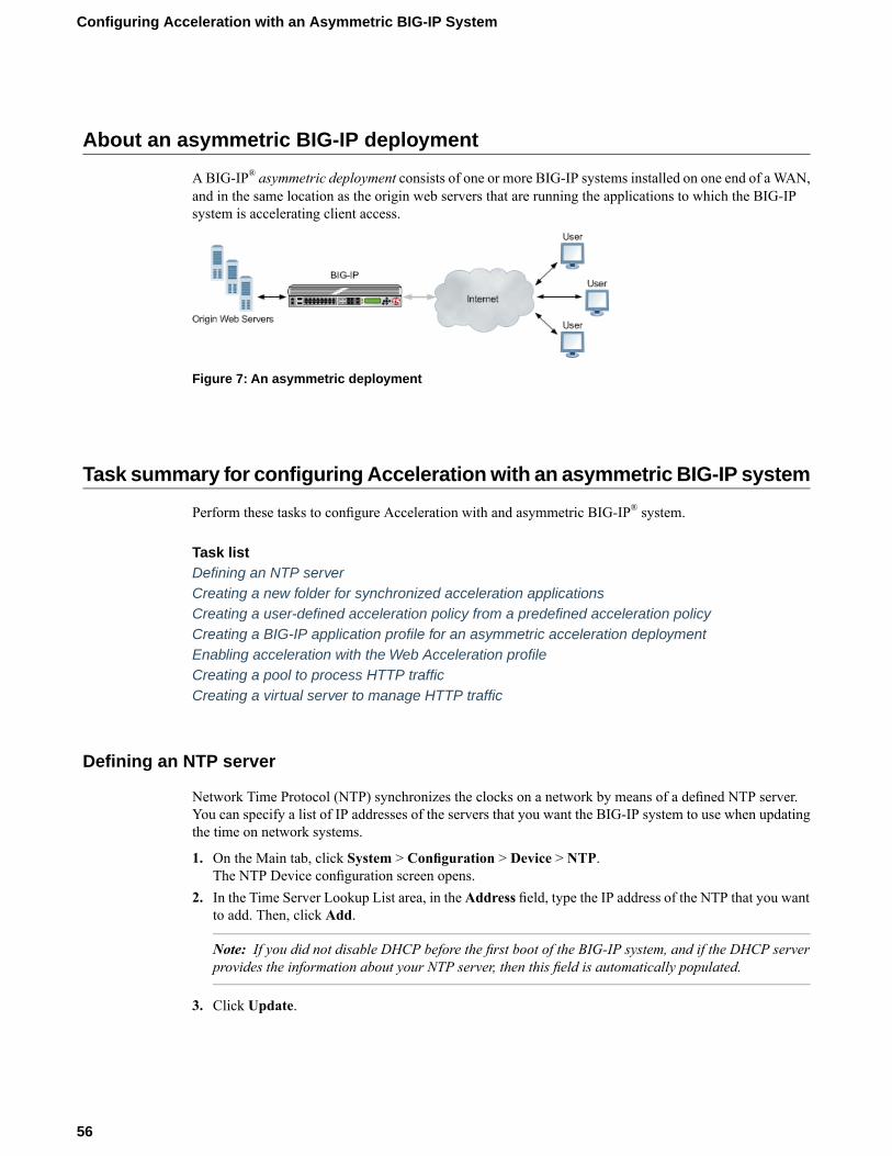
About an asymmetric BIG-IP deployment
ABIG-IP® asymmetric deployment consists of one or more BIG-IP systems installed on one end of aWAN,and in the same location as the origin web servers that are running the applications to which the BIG-IPsystem is accelerating client access.
Figure 7: An asymmetric deployment
Task summary for configuring Acceleration with an asymmetric BIG-IP system
Perform these tasks to configure Acceleration with and asymmetric BIG-IP® system.
Task listDefining an NTP serverCreating a new folder for synchronized acceleration applicationsCreating a user-defined acceleration policy from a predefined acceleration policyCreating a BIG-IP application profile for an asymmetric acceleration deploymentEnabling acceleration with the Web Acceleration profileCreating a pool to process HTTP trafficCreating a virtual server to manage HTTP traffic
Defining an NTP server
Network Time Protocol (NTP) synchronizes the clocks on a network by means of a defined NTP server.You can specify a list of IP addresses of the servers that you want the BIG-IP system to use when updatingthe time on network systems.
1. On the Main tab, click System > Configuration > Device > NTP.The NTP Device configuration screen opens.
2. In the Time Server Lookup List area, in the Address field, type the IP address of the NTP that you wantto add. Then, click Add.
Note: If you did not disable DHCP before the first boot of the BIG-IP system, and if the DHCP serverprovides the information about your NTP server, then this field is automatically populated.
3. Click Update.
56
Configuring Acceleration with an Asymmetric BIG-IP System
Creating a new folder for synchronized acceleration applications
You can organize synchronized acceleration applications in folders.
1. On the Main tab, click Acceleration >Web Application > Symmetric Folders.2. Click Create.3. In the Folder Name field, type a name for the folder.4. From the Device Group list, select a Sync-Only device group.5. (Optional) In the Description field, type a description.6. Click Save.
A folder for organizing synchronized acceleration applications is available.
Creating a user-defined acceleration policy from a predefined acceleration policy
You can copy a predefined acceleration policy, andmodify applicable nodes, matching rules, and accelerationrules, to create a user-defined acceleration policy.
1. On the Main tab, click Acceleration >Web Application > Policies.The Policies screen displays a list of existing acceleration policies.
2. In the Tools column, click Copy for the predefined acceleration policy you want to copy.3. Name the policy.4. Specify a folder, based on your configuration.
• For a symmetric or farm configuration, from the Sync Folder list, select the name of a symmetricfolder.
• For an asymmetric configuration, from the Sync Folder list, select No Selection.
5. Click Copy.6. Click the name of the new user-defined acceleration policy.7. Create, delete, or modify nodes, matching rules, and acceleration rules, as necessary.8. Publish the acceleration policy.
a) Click Publish.b) In the Comment field, type a description.c) Click Publish Now.
The user-defined acceleration policy appears in the Policy column.
Creating a BIG-IP application profile for an asymmetric acceleration deployment
An application profile provides the key information that the BIG-IP device needs to appropriately handlerequests to your site's web applications.
1. On the Main tab, click Acceleration >Web Application > Applications.The Applications List screen opens.
2. Click Create.3. Name the application.
57
BIG-IP® Acceleration: Network Configuration
4. In the Description field, type a description.5. Specify the type of acceleration policy:
• Click the name of a user-defined acceleration policy.• Click the name of a predefined acceleration policy.
6. In the Requested Host field, type each domain name (host name), or IP address, that might appear inHTTP requests for your web application.The specified domain names, or IP addresses, are defined in the host map for the application profile.
7. Click Save.
The application profile appears in the Application column on the Applications List screen.
Enabling acceleration with the Web Acceleration profile
A BIG-IP® Acceleration application for aWeb Application must be available.
The Web Acceleration profile enables acceleration by using applications that run on a virtual server.
1. On the Main tab, click Local Traffic > Profiles > Services >Web Acceleration.The Web Acceleration profile list screen opens.
2. Click the name of a profile.3. Select the Custom check box.4. For theWA Applications setting, select an application in the Available list and click Enable.
The application is listed in the Enabled list.5. Click Update.
Acceleration is enabled through the BIG-IP application in the Web Acceleration profile.
Creating a pool to process HTTP traffic
You can create a pool of web servers to process HTTP requests.
1. On the Main tab, click Local Traffic > Pools.The Pool List screen opens.
2. Click Create.The New Pool screen opens.
3. In the Name field, type a unique name for the pool.4. For theHealth Monitors setting, from the Available list, select the httpmonitor, and click << to move
the monitor to the Active list.5. From the Load Balancing Method list, select how the system distributes traffic to members of this
pool.The default is Round Robin.
6. For the Priority Group Activation setting, specify how to handle priority groups:
• Select Disabled to disable priority groups. This is the default option.• Select Less than, and in the Available Members field type the minimum number of members that
must remain available in each priority group in order for traffic to remain confined to that group.
7. Using the New Members setting, add each resource that you want to include in the pool:
58
Configuring Acceleration with an Asymmetric BIG-IP System
a) Type an IP address in the Address field.b) Type 80 in the Service Port field, or select HTTP from the list.c) (Optional) Type a priority number in the Priority field.d) Click Add.
8. Click Finished.
The new pool appears in the Pools list.
Creating a virtual server to manage HTTP traffic
You can create a virtual server to manage HTTP traffic as either a host virtual server or a network virtualserver.
1. On the Main tab, click Local Traffic > Virtual Servers.The Virtual Server List screen opens.
2. Click the Create button.The New Virtual Server screen opens.
3. In the Name field, type a unique name for the virtual server.4. For the Destination setting, in the Address field, type the IP address you want to use for the virtual
server.The IP address you type must be available and not in the loopback network.
5. In the Service Port field, type 80, or select HTTP from the list.6. From the HTTP Profile list, select http.7. From the HTTP Compression Profile list, select one of the following profiles:
• httpcompression• wan-optimized-compression• A customized profile
8. From theWebAcceleration Profile list, select one of the following profiles with an enabled application:
• optimized-acceleration• optimized-caching• webacceleration• A customized profile
9. In the Resources area of the screen, from the Default Pool list, select a pool name.10. Click Finished.
The HTTP virtual server appears in the list of existing virtual servers on the Virtual Server List screen.
Implementation result
BIG-IP® acceleration is configured asymmetrically to accelerate HTTP traffic.
59
BIG-IP® Acceleration: Network Configuration


Chapter
5Setting Up an iSession Connection Using the Quick StartScreen
• Overview: Setting up an iSession connectionusing the Quick Start screen
Overview: Setting up an iSession connection using the Quick Start screen
The Quick Start screen for WAN acceleration provides the settings you need to configure an iSession™
connection on one side of the WAN. To complete the iSession connection, you must use the Quick Startscreen on the BIG-IP system on the other side of the WAN.
The Quick Start screen is for the initial BIG-IP symmetric acceleration setup. To change the settings forany iSession acceleration objects after you have completed the initial configuration on the Quick Startscreen, use the screen that pertains to that object. For example, to change the settings for the local endpoint,use the Local Endpoint screen.
Setting up an iSession connection using the Quick Start screen
You cannot view the Quick Start screen until you have defined at least one VLAN and at least one self IPon a configured BIG-IP® system that is licensed and provisioned for acceleration.
Use the Quick Start screen to quickly set up the iSession™ endpoints on a BIG-IP system. To optimizeWANtraffic, you must configure the iSession endpoints on the BIG-IP systems on both sides of the WAN.
1. Log in to the BIG-IP system that you want to configure.The default login value for both user name and password is admin.
2. On the Main tab, click Acceleration > Quick Start > Symmetric Properties.3. In theWAN Self IP Address field, type the local endpoint IP address, if it is not already displayed.
This IP address must be in the same subnet as a self IP address on the BIG-IP system, and to make surethat dynamic discovery properly detects this endpoint, the IP address must be the same as a self IPaddress on the BIG-IP system.
4. Verify that the Discovery setting is set to Enabled.If you disable theDiscovery setting, or discovery fails, youmust manually configure any remote endpointsand advertised routes.
5. Specify the VLANs on which the virtual servers on this system receive incoming traffic.DescriptionOption
Select the VLANs that receive incoming LAN traffic destined for theWAN.
LAN VLANs
Select the VLANs that receive traffic from the WAN through aniSession™ connection.
WAN VLANs
6. In the Authentication area, for the Outbound iSession to WAN setting, select the SSL profile to usefor all encrypted outbound iSession connections.To get WAN optimization up and running, you can use the default selection serverssl, but you need tocustomize this profile for your production environment.
7. For the Inbound iSession from WAN setting, select the SSL profile to use on the incoming iSessionconnection.To get WAN optimization up and running, you can use the default selection wom-default-clientssl.
Note: If you configure the iSession connection to not always encrypt the traffic between the endpoints,this profile must be a client SSL profile for which the Non-SSL Connections setting is enabled, such aswom-default-clientssl.
62
Setting Up an iSession Connection Using the Quick Start Screen

8. In the IP Encapsulation area, from the IP Encapsulation Type list, select the encapsulation type, if any,for outbound iSession traffic.a) If you select FEC, select a FEC profile from the FEC Profile list that appears, or retain the default,
default-ipsec-policy-isession.b) If you select IPsec, select an IPsec policy from the IPSEC Policy list that appears, or retain the
default, default-ipsec-policy-isession.c) If you select IPIP, the system uses the IP over IP tunneling protocol, and no additional encapsulation
setting is necessary.d) If you selectGRE, select a GRE profile from theGRE Profile list that appears, or retain the default,
gre.
9. Click Apply.
To complete the setup, repeat this task on the BIG-IP system on the other side of the WAN.
63
BIG-IP® Acceleration: Network Configuration


Chapter
6Troubleshooting the iSession Configuration
• About symmetric optimization diagnostics• Symmetric optimization diagnostic error
messages• Troubleshooting network connectivity for
iSession configurations• Running symmetric optimization
configuration diagnostics
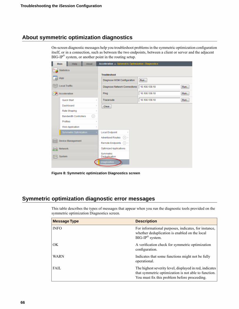
About symmetric optimization diagnostics
On-screen diagnostic messages help you troubleshoot problems in the symmetric optimization configurationitself, or in a connection, such as between the two endpoints, between a client or server and the adjacentBIG-IP® system, or another point in the routing setup.
Figure 8: Symmetric optimization Diagnostics screen
Symmetric optimization diagnostic error messages
This table describes the types of messages that appear when you run the diagnostic tools provided on thesymmetric optimization Diagnostics screen.
DescriptionMessage Type
For informational purposes, indicates, for instance,whether deduplication is enabled on the localBIG-IP® system.
INFO
A verification check for symmetric optimizationconfiguration.
OK
Indicates that some functions might not be fullyoperational.
WARN
The highest severity level, displayed in red, indicatesthat symmetric optimization is not able to function.You must fix this problem before proceeding.
FAIL
66
Troubleshooting the iSession Configuration
Troubleshooting network connectivity for iSession configurations
Before you start this task, you must have finished configuring the iSession™ connection between BIG-IP®
systems on opposite sides of the WAN, and the systems have discovered their iSession remote endpoints.
You can use these diagnostics from the local BIG-IP system to the remote server to verify the BIG-IPsystem-to-server routes, in case the remote BIG-IP system is not configured correctly.
1. On the Main tab, click Acceleration > Symmetric Optimization > Diagnostics.2. In the Diagnose Network Connections field, type the IP address of a remote iSession endpoint, and
click the Run button.Network connection diagnostic information appears on the screen. Use this information to determinewhether there is a connection between the local iSession endpoint and the remote iSession endpoint youspecify.
3. Use the data displayed on the screen to make corrections.4. In the Ping field, type the IP address of a host, for example, a remote BIG-IP system, and click the Run
button.Use this utility to determine whether other BIG-IP systems can be reached through the routed WANnetwork. If ping fails, verify the configuration of your VLANs, self IP addresses, and default gateway.
5. Use the data displayed on the screen to make corrections, such as properly defining the local and remoteroutes.Ping results appear on the screen. If a ping fails, you can use Traceroute to pinpoint the location of afailure in the network.
6. In the Traceroute field, type the destination IP address you want to reach, and click the Run button.7. Use the data displayed on the screen to correct any routing problems. This data can reveal whether the
problem is in the WAN, or is local to either of the BIG-IP systems. You can also view the observedlatency, if any, along the WAN path.
Running symmetric optimization configuration diagnostics
Before you start this task, you must have finished configuring the iSession™ connection between BIG-IP®
systems on opposite sides of the WAN.
The configuration diagnostics verify that you have set up symmetric optimization properly.
1. On the Main tab, click Acceleration > Symmetric Optimization > Diagnostics.2. Next to Diagnose WOMConfiguration, click the Run button to verify that symmetric optimization is
configured correctly.
Note: If you have not sent traffic through the designated network, dynamic discovery might not havediscovered the remote endpoint.
In the following example, the SDD codec mismatch on the peers causes a warning message, becausesymmetric optimization features other than deduplication are functional.
67
BIG-IP® Acceleration: Network Configuration
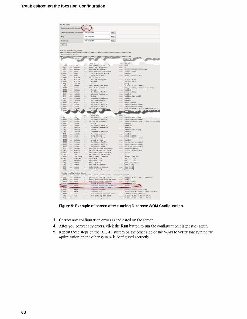
Figure 9: Example of screen after running Diagnose WOM Configuration.
3. Correct any configuration errors as indicated on the screen.4. After you correct any errors, click the Run button to run the configuration diagnostics again.5. Repeat these steps on the BIG-IP system on the other side of the WAN to verify that symmetric
optimization on the other system is configured correctly.
68
Troubleshooting the iSession Configuration
Chapter
7Configuring a One-Arm Deployment Using WCCPv2
• Overview: Configuring a one-arm deploymentusing WCCPv2
• About WCCPv2 redirection on the BIG-IPsystem
• Before you begin configuring an iSessionconnection
• Task summary• Implementation result
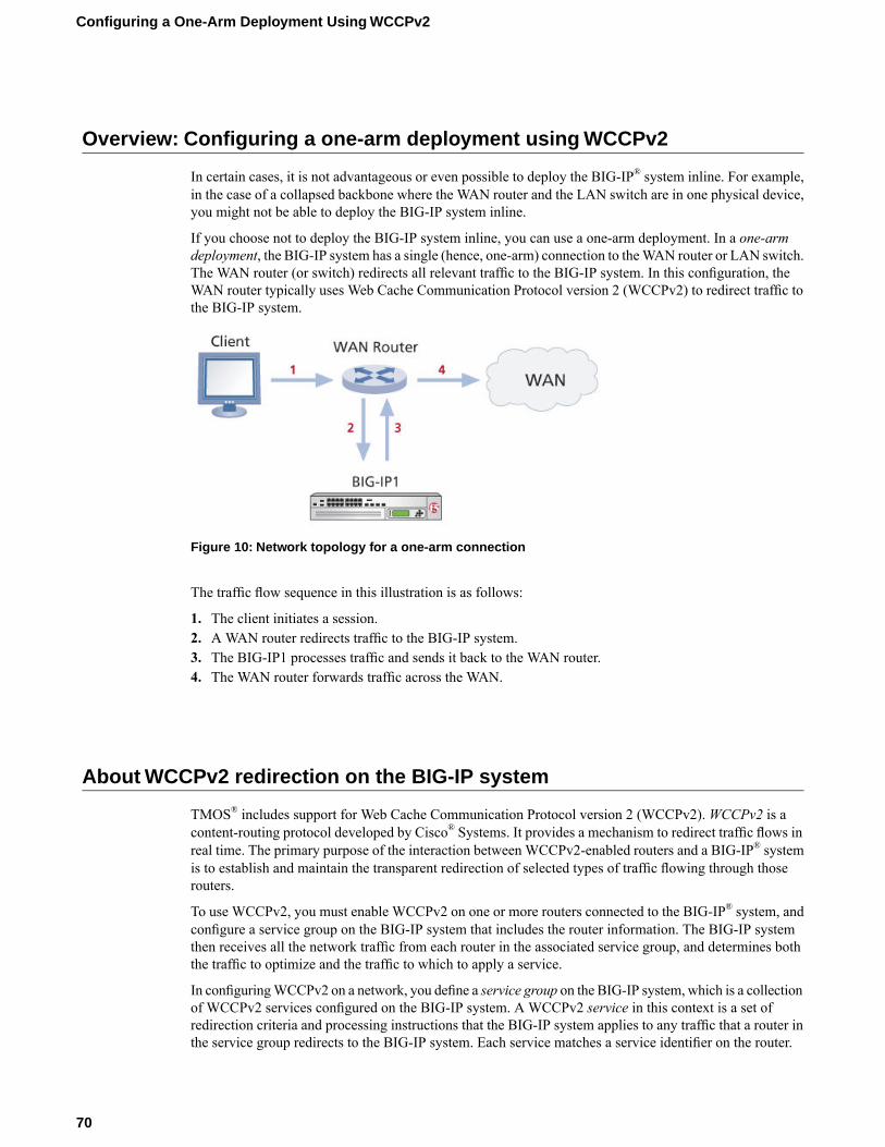
Overview: Configuring a one-arm deployment using WCCPv2
In certain cases, it is not advantageous or even possible to deploy the BIG-IP® system inline. For example,in the case of a collapsed backbone where the WAN router and the LAN switch are in one physical device,you might not be able to deploy the BIG-IP system inline.
If you choose not to deploy the BIG-IP system inline, you can use a one-arm deployment. In a one-armdeployment, the BIG-IP system has a single (hence, one-arm) connection to theWAN router or LAN switch.The WAN router (or switch) redirects all relevant traffic to the BIG-IP system. In this configuration, theWAN router typically uses Web Cache Communication Protocol version 2 (WCCPv2) to redirect traffic tothe BIG-IP system.
Figure 10: Network topology for a one-arm connection
The traffic flow sequence in this illustration is as follows:
1. The client initiates a session.2. AWAN router redirects traffic to the BIG-IP system.3. The BIG-IP1 processes traffic and sends it back to the WAN router.4. The WAN router forwards traffic across the WAN.
About WCCPv2 redirection on the BIG-IP system
TMOS® includes support for Web Cache Communication Protocol version 2 (WCCPv2).WCCPv2 is acontent-routing protocol developed by Cisco® Systems. It provides a mechanism to redirect traffic flows inreal time. The primary purpose of the interaction between WCCPv2-enabled routers and a BIG-IP® systemis to establish and maintain the transparent redirection of selected types of traffic flowing through thoserouters.
To use WCCPv2, you must enable WCCPv2 on one or more routers connected to the BIG-IP® system, andconfigure a service group on the BIG-IP system that includes the router information. The BIG-IP systemthen receives all the network traffic from each router in the associated service group, and determines boththe traffic to optimize and the traffic to which to apply a service.
In configuringWCCPv2 on a network, you define a service group on the BIG-IP system, which is a collectionof WCCPv2 services configured on the BIG-IP system. A WCCPv2 service in this context is a set ofredirection criteria and processing instructions that the BIG-IP system applies to any traffic that a router inthe service group redirects to the BIG-IP system. Each service matches a service identifier on the router.
70
Configuring a One-Arm Deployment Using WCCPv2
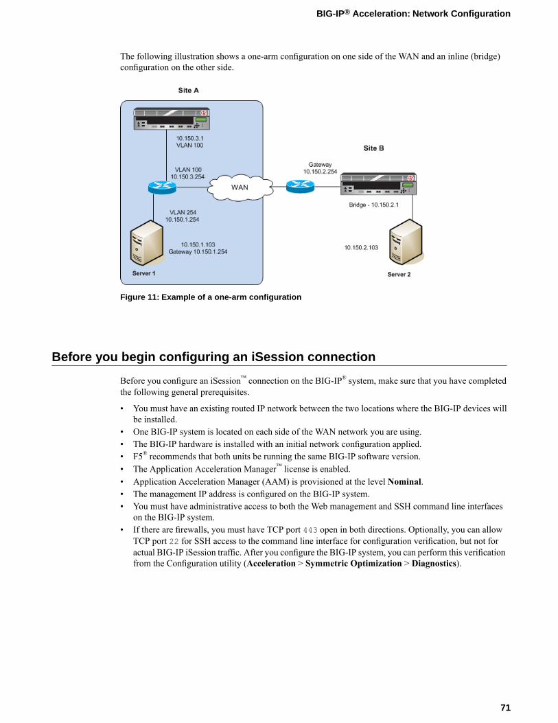
The following illustration shows a one-arm configuration on one side of the WAN and an inline (bridge)configuration on the other side.
Figure 11: Example of a one-arm configuration
Before you begin configuring an iSession connection
Before you configure an iSession™ connection on the BIG-IP® system, make sure that you have completedthe following general prerequisites.
• You must have an existing routed IP network between the two locations where the BIG-IP devices willbe installed.
• One BIG-IP system is located on each side of the WAN network you are using.• The BIG-IP hardware is installed with an initial network configuration applied.• F5® recommends that both units be running the same BIG-IP software version.• The Application Acceleration Manager™ license is enabled.• Application Acceleration Manager (AAM) is provisioned at the level Nominal.• The management IP address is configured on the BIG-IP system.• You must have administrative access to both the Web management and SSH command line interfaces
on the BIG-IP system.• If there are firewalls, you must have TCP port 443 open in both directions. Optionally, you can allow
TCP port 22 for SSH access to the command line interface for configuration verification, but not foractual BIG-IP iSession traffic. After you configure the BIG-IP system, you can perform this verificationfrom the Configuration utility (Acceleration > Symmetric Optimization > Diagnostics).
71
BIG-IP® Acceleration: Network Configuration

Task summary
To use WCCPv2 for traffic redirection, you configure a service group on the BIG-IP® system that includesat least one service. You also configure this service on theWCCPv2-enabled router connected to the BIG-IPsystem.
For optimization, you also need to configure the BIG-IP system on the other side of the WAN to completethe connection. The BIG-IP system on the other side of the WAN can be set up in either a one-arm or inlineconfiguration.
Note: The example described in this implementation applies to the Cisco 3750 and Cat 6500 routers.
Prerequisites
Before you begin configuringWCCPv2 for traffic redirection, ensure that you have performed the followingactions on the other devices in your network.
• The interface and associated VLAN have been configured on the router or switch. For instructions, referto the Cisco documentation for your device.
• IP addresses have been assigned on the Cisco router or switch interface. Note the router identificationaddress, which you will use when configuring WCCPv2 on the BIG-IP system.
Task listCreating a VLAN for a one-arm deploymentCreating a self IP address for a one-arm deploymentDefining a routeConfiguring WCCPv2Verifying connectivityVerifying WCCPv2 configuration for one-arm deploymentCreating an iSession connectionValidating iSession configuration in a one-arm deploymentConfiguring the Cisco router for a one-arm deployment using WCCPv2Viewing pertinent configuration details from the command line
Creating a VLAN for a one-arm deployment
For a one-arm deployment, you create only one VLAN on the BIG-IP® system, because the system has onlya single connection to the WAN router or switch.
1. On the Main tab, click Network > VLANs.The VLAN List screen opens.
2. Click Create.The New VLAN screen opens.
3. In the Name field, type wan.4. In the Tag field, type a numeric tag, from 1 to 4094 for the VLAN, depending on your network
configuration.5. For the Interfaces setting, click an interface number in theAvailable list, and move the selected interface
to the Untagged or Tagged list, depending on your network configuration.6. Click Finished.
72
Configuring a One-Arm Deployment Using WCCPv2
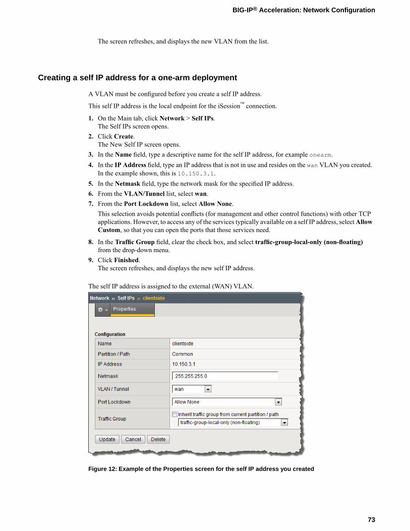
The screen refreshes, and displays the new VLAN from the list.
Creating a self IP address for a one-arm deployment
A VLAN must be configured before you create a self IP address.
This self IP address is the local endpoint for the iSession™ connection.
1. On the Main tab, click Network > Self IPs.The Self IPs screen opens.
2. Click Create.The New Self IP screen opens.
3. In the Name field, type a descriptive name for the self IP address, for example onearm.4. In the IP Address field, type an IP address that is not in use and resides on the wan VLAN you created.
In the example shown, this is 10.150.3.1.5. In the Netmask field, type the network mask for the specified IP address.6. From the VLAN/Tunnel list, select wan.7. From the Port Lockdown list, select Allow None.
This selection avoids potential conflicts (for management and other control functions) with other TCPapplications. However, to access any of the services typically available on a self IP address, selectAllowCustom, so that you can open the ports that those services need.
8. In the Traffic Group field, clear the check box, and select traffic-group-local-only (non-floating)from the drop-down menu.
9. Click Finished.The screen refreshes, and displays the new self IP address.
The self IP address is assigned to the external (WAN) VLAN.
Figure 12: Example of the Properties screen for the self IP address you created
73
BIG-IP® Acceleration: Network Configuration
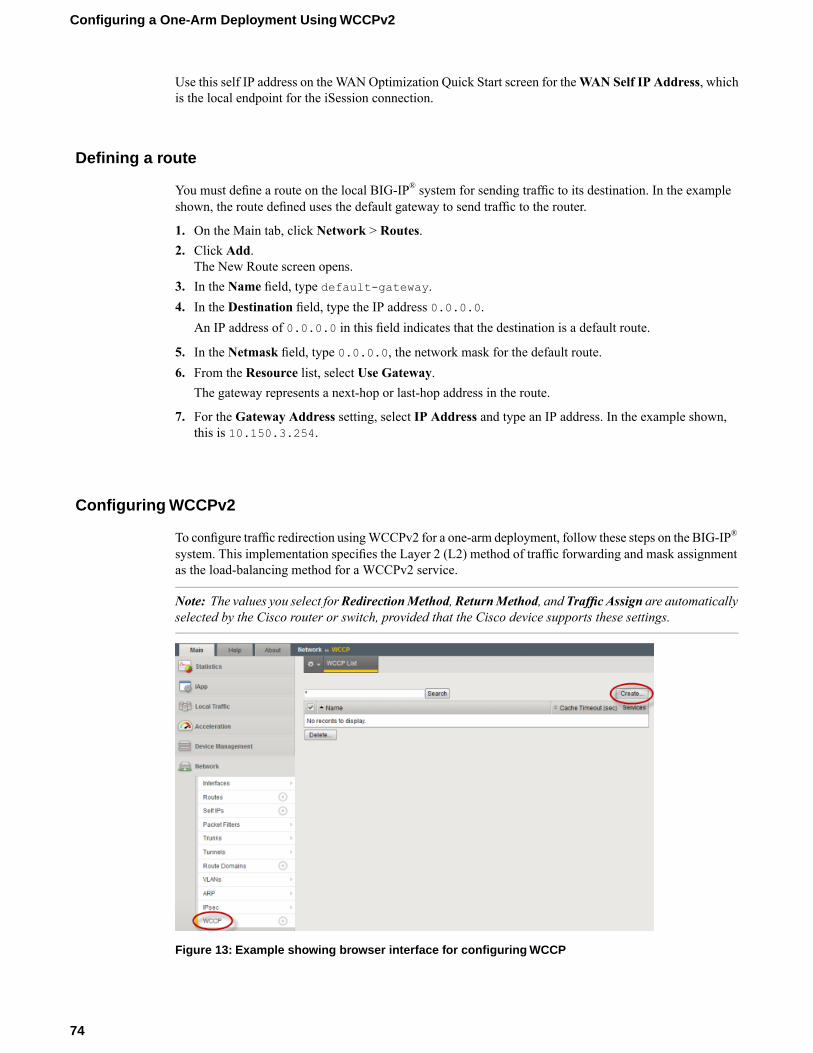
Use this self IP address on the WAN Optimization Quick Start screen for theWAN Self IP Address, whichis the local endpoint for the iSession connection.
Defining a route
You must define a route on the local BIG-IP® system for sending traffic to its destination. In the exampleshown, the route defined uses the default gateway to send traffic to the router.
1. On the Main tab, click Network > Routes.2. Click Add.
The New Route screen opens.3. In the Name field, type default-gateway.4. In the Destination field, type the IP address 0.0.0.0.
An IP address of 0.0.0.0 in this field indicates that the destination is a default route.
5. In the Netmask field, type 0.0.0.0, the network mask for the default route.6. From the Resource list, select Use Gateway.
The gateway represents a next-hop or last-hop address in the route.
7. For the Gateway Address setting, select IP Address and type an IP address. In the example shown,this is 10.150.3.254.
Configuring WCCPv2
To configure traffic redirection usingWCCPv2 for a one-arm deployment, follow these steps on the BIG-IP®
system. This implementation specifies the Layer 2 (L2) method of traffic forwarding and mask assignmentas the load-balancing method for a WCCPv2 service.
Note: The values you select forRedirectionMethod,ReturnMethod, and Traffic Assign are automaticallyselected by the Cisco router or switch, provided that the Cisco device supports these settings.
Figure 13: Example showing browser interface for configuring WCCP
74
Configuring a One-Arm Deployment Using WCCPv2

1. On the Main tab of the BIG-IP® system user interface, click Network >WCCP.2. Click the Create button.
The New WCCP List screen opens.3. In the Service Group field, type a name for the service group, for example, service-wccp.4. In the Service field, type a service group identifier, which is a number between 51 and 255.
This number must match the service ID you configure on the Cisco router. In the illustration shown,this number is 75.
5. From the Port Type list, select Destination.If you specify a port in the Port List , this setting specifies the port on which the server listens forincoming traffic that has been redirected by WCCP. For best results, select Destination, even if you donot specify a port.
6. From the Redirection Method list, select L2.This setting specifies the method the router uses to redirect traffic to the BIG-IP system. Typically, L2has a faster throughput rate than GRE, but GRE traffic has the advantage that it can be forwarded by aLayer-3 router. This example uses L2.
Note: The router or switch uses the same redirection method, if supported.
7. From the Return Method list, select L2.This setting specifies the method the BIG-IP system uses to return pass-through traffic to the router.Typically, L2 has a faster throughput rate than GRE, but GRE traffic has the advantage that it can beforwarded by a Layer-3 router. This example uses L2.
Note: The router or switch uses the same return method, if supported.
8. From the Traffic Assign list, selectMask.This setting specifies whether load balancing is achieved by a hash algorithm or a mask. This exampleuses a mask.
Note: The router or switch uses the same setting, if supported.
9. In the Routers field, type the IP address of the Cisco router, and click Add.In the illustration shown, this is 10.150.3.254.
Important: Do not use a secondary IP address for the Cisco router or switch.
10. In the Port List field, select an application, or leave it blank to indicate all ports.11. For the Router Identifier setting, type the Router Identifier IP address of the router.
If you do not know the Router Identifier IP address, consult the Cisco documentation that applies to therouter or switch you are using.
12. In the Client ID field, type the IP address of the VLAN that connects to the Cisco router.In the illustration shown, this is 10.150.3.1.
13. Click Finished.
The BIG-IP is configured for WCCPv2 traffic redirection in a one-arm deployment. The completed screenlooks similar to the following example.
75
BIG-IP® Acceleration: Network Configuration
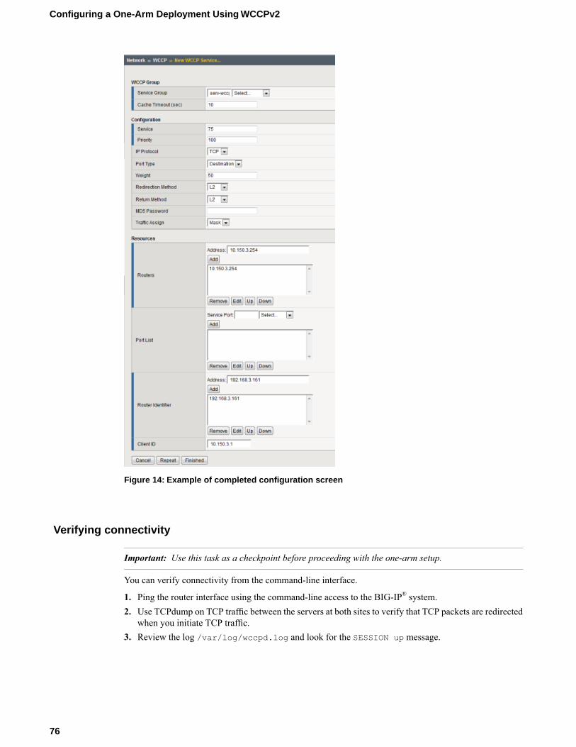
Figure 14: Example of completed configuration screen
Verifying connectivity
Important: Use this task as a checkpoint before proceeding with the one-arm setup.
You can verify connectivity from the command-line interface.
1. Ping the router interface using the command-line access to the BIG-IP® system.2. Use TCPdump on TCP traffic between the servers at both sites to verify that TCP packets are redirected
when you initiate TCP traffic.3. Review the log /var/log/wccpd.log and look for the SESSION up message.
76
Configuring a One-Arm Deployment Using WCCPv2
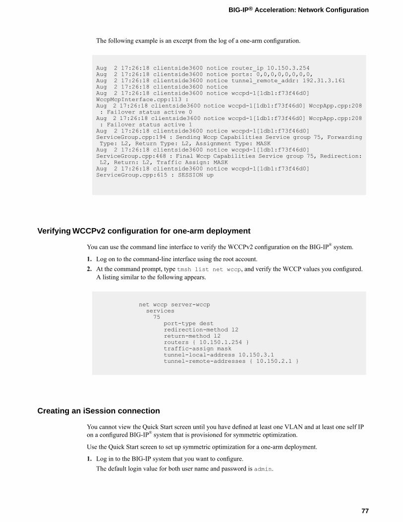
The following example is an excerpt from the log of a one-arm configuration.
Aug 2 17:26:18 clientside3600 notice router_ip 10.150.3.254Aug 2 17:26:18 clientside3600 notice ports: 0,0,0,0,0,0,0,0,Aug 2 17:26:18 clientside3600 notice tunnel_remote_addr: 192.31.3.161Aug 2 17:26:18 clientside3600 noticeAug 2 17:26:18 clientside3600 notice wccpd-1[1db1:f73f46d0]WccpMcpInterface.cpp:113 :Aug 2 17:26:18 clientside3600 notice wccpd-1[1db1:f73f46d0] WccpApp.cpp:208: Failover status active 0Aug 2 17:26:18 clientside3600 notice wccpd-1[1db1:f73f46d0] WccpApp.cpp:208: Failover status active 1Aug 2 17:26:18 clientside3600 notice wccpd-1[1db1:f73f46d0]ServiceGroup.cpp:194 : Sending Wccp Capabilities Service group 75, ForwardingType: L2, Return Type: L2, Assignment Type: MASKAug 2 17:26:18 clientside3600 notice wccpd-1[1db1:f73f46d0]ServiceGroup.cpp:468 : Final Wccp Capabilities Service group 75, Redirection:L2, Return: L2, Traffic Assign: MASKAug 2 17:26:18 clientside3600 notice wccpd-1[1db1:f73f46d0]ServiceGroup.cpp:615 : SESSION up
Verifying WCCPv2 configuration for one-arm deployment
You can use the command line interface to verify the WCCPv2 configuration on the BIG-IP® system.
1. Log on to the command-line interface using the root account.2. At the command prompt, type tmsh list net wccp, and verify the WCCP values you configured.
A listing similar to the following appears.
net wccp server-wccpservices75
port-type destredirection-method l2return-method l2routers { 10.150.1.254 }traffic-assign masktunnel-local-address 10.150.3.1tunnel-remote-addresses { 10.150.2.1 }
Creating an iSession connection
You cannot view the Quick Start screen until you have defined at least one VLAN and at least one self IPon a configured BIG-IP® system that is provisioned for symmetric optimization.
Use the Quick Start screen to set up symmetric optimization for a one-arm deployment.
1. Log in to the BIG-IP system that you want to configure.The default login value for both user name and password is admin.
77
BIG-IP® Acceleration: Network Configuration

2. On the Main tab, click Acceleration > Quick Start > Symmetric Properties.3. In theWAN Self IP Address field, type the local endpoint IP address.
In the example shown, this is 10.150.3.1.
4. Verify that the Discovery setting is set to Enabled.If you disable theDiscovery setting, or discovery fails, youmust manually configure any remote endpointsand advertised routes.
5. In the Select VLANs field, select the wanVLAN for both theLANVLANs andWANVLANs settings.You select only one VLAN, because the system has only a single connection to the WAN router orswitch.
6. Click Apply.
This example shows a completed Quick Start screen.
Figure 15: Example of completed Quick Start screen
After you configure the iSession™ endpoints, use an iApp template to select the application traffic foroptimization. ClickAcceleration >Quick Start >Deploy Applications. ClickCreate, from theTemplatelist select f5.replication, and follow the online instructions.
78
Configuring a One-Arm Deployment Using WCCPv2
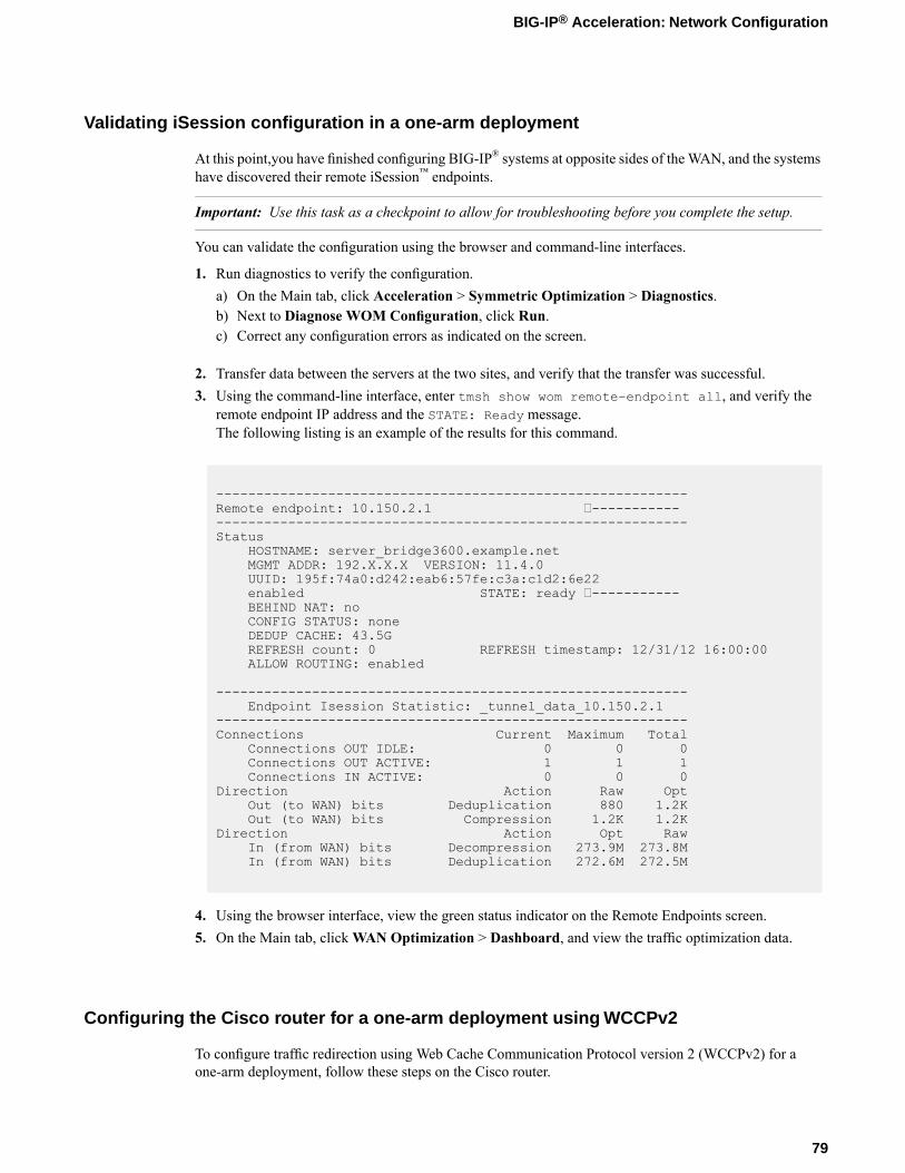
Validating iSession configuration in a one-arm deployment
At this point,you have finished configuring BIG-IP® systems at opposite sides of theWAN, and the systemshave discovered their remote iSession™ endpoints.
Important: Use this task as a checkpoint to allow for troubleshooting before you complete the setup.
You can validate the configuration using the browser and command-line interfaces.
1. Run diagnostics to verify the configuration.a) On the Main tab, click Acceleration > Symmetric Optimization > Diagnostics.b) Next to Diagnose WOM Configuration, click Run.c) Correct any configuration errors as indicated on the screen.
2. Transfer data between the servers at the two sites, and verify that the transfer was successful.3. Using the command-line interface, enter tmsh show wom remote-endpoint all, and verify the
remote endpoint IP address and the STATE: Ready message.The following listing is an example of the results for this command.
-----------------------------------------------------------Remote endpoint: 10.150.2.1 ----------------------------------------------------------------------Status
HOSTNAME: server_bridge3600.example.netMGMT ADDR: 192.X.X.X VERSION: 11.4.0UUID: 195f:74a0:d242:eab6:57fe:c3a:c1d2:6e22enabled STATE: ready -----------BEHIND NAT: noCONFIG STATUS: noneDEDUP CACHE: 43.5GREFRESH count: 0 REFRESH timestamp: 12/31/12 16:00:00ALLOW ROUTING: enabled
-----------------------------------------------------------Endpoint Isession Statistic: _tunnel_data_10.150.2.1
-----------------------------------------------------------Connections Current Maximum Total
Connections OUT IDLE: 0 0 0Connections OUT ACTIVE: 1 1 1Connections IN ACTIVE: 0 0 0
Direction Action Raw OptOut (to WAN) bits Deduplication 880 1.2KOut (to WAN) bits Compression 1.2K 1.2K
Direction Action Opt RawIn (from WAN) bits Decompression 273.9M 273.8MIn (from WAN) bits Deduplication 272.6M 272.5M
4. Using the browser interface, view the green status indicator on the Remote Endpoints screen.5. On the Main tab, clickWAN Optimization > Dashboard, and view the traffic optimization data.
Configuring the Cisco router for a one-arm deployment using WCCPv2
To configure traffic redirection using Web Cache Communication Protocol version 2 (WCCPv2) for aone-arm deployment, follow these steps on the Cisco router.
79
BIG-IP® Acceleration: Network Configuration

1. Configure the service ID that you configured on the BIG-IP® device.a) Enable WCCP globally.b) In Command mode, configure the service ID; for example, 75.
In the example shown, the command line might look like the following.
(config)#ip wccp 75
2. Using the router interface that is connected to the client fromwhich you want to redirect traffic, associatethe VLAN with the service ID you configured.In the example shown, the command-line interface might look like the following.
(config)#interface vlan 254(config)#ip wccp 75 redirect in
The following listing is an example of the information displayed for a Cisco router configured to redirecttraffic to the BIG-IP system using WCCPv2.
Clientside_Top_switch#sh runBuilding configuration...Current configuration : 4848 bytesversion 12.2no service padhostname Clientside_Top_switch!no aaa new-modelswitch 1 provision ws-c3750g-48tssystem mtu routing 1500vtp mode transparentip subnet-zeroip routingip wccp 75!interface GigabitEthernet1/0/4switchport access vlan 200switchport mode access!interface GigabitEthernet1/0/5switchport access vlan 100switchport mode access!interface GigabitEthernet1/0/6!interface GigabitEthernet1/0/7switchport access vlan 254switchport mode access!interface Vlan1ip address 192.31.3.161 255.255.255.0!interface Vlan100ip address 10.15.3.254 255.255.255.0!interface Vlan200ip address 10.15.2.254 255.255.255.0!interface Vlan254ip address 10.15.1.254 255.255.255.0
80
Configuring a One-Arm Deployment Using WCCPv2
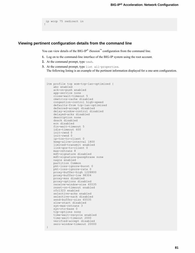
ip wccp 75 redirect in!
Viewing pertinent configuration details from the command line
You can view details of the BIG-IP® iSession™ configuration from the command line.
1. Log on to the command-line interface of the BIG-IP system using the root account.2. At the command prompt, type tmsh.3. At the command prompt, type list all-properties.
The following listing is an example of the pertinent information displayed for a one-arm configuration.
ltm profile tcp wom-tcp-lan-optimized {abc enabledack-on-push enabledapp-service noneclose-wait-timeout 5cmetrics-cache disabledcongestion-control high-speeddefaults-from tcp-lan-optimizeddeferred-accept disableddelay-window-control disableddelayed-acks disableddescription nonedsack disabledecn disabledfin-wait-timeout 5idle-timeout 600init-cwnd 0init-rwnd 0ip-tos-to-client 0keep-alive-interval 1800limited-transmit enabledlink-qos-to-client 0max-retrans 8md5-signature disabledmd5-signature-passphrase nonenagle enabledpartition Commonpkt-loss-ignore-burst 0pkt-loss-ignore-rate 0proxy-buffer-high 1228800proxy-buffer-low 98304proxy-mss disabledproxy-options disabledreceive-window-size 65535reset-on-timeout enabledrfc1323 enabledselective-acks enabledselective-nack disabledsend-buffer-size 65535slow-start disabledsyn-max-retrans 3syn-rto-base 0tcp-options nonetime-wait-recycle enabledtime-wait-timeout 2000verified-accept disabledzero-window-timeout 20000
}
81
BIG-IP® Acceleration: Network Configuration

ltm profile tcp wom-tcp-wan-optimized {abc enabledack-on-push disabledapp-service noneclose-wait-timeout 5cmetrics-cache enabledcongestion-control high-speeddefaults-from tcp-wan-optimizeddeferred-accept disableddelay-window-control disableddelayed-acks disableddescription nonedsack disabledecn disabledfin-wait-timeout 5idle-timeout 600init-cwnd 0init-rwnd 0ip-tos-to-client 0keep-alive-interval 1800limited-transmit enabledlink-qos-to-client 0max-retrans 8md5-signature disabledmd5-signature-passphrase nonenagle enabledpartition Commonpkt-loss-ignore-burst 8pkt-loss-ignore-rate 10000proxy-buffer-high 196608proxy-buffer-low 131072proxy-mss disabledproxy-options disabledreceive-window-size 2048000reset-on-timeout enabledrfc1323 enabledselective-acks enabledselective-nack enabledsend-buffer-size 2048000slow-start disabledsyn-max-retrans 3syn-rto-base 0tcp-options nonetime-wait-recycle enabledtime-wait-timeout 2000verified-accept disabledzero-window-timeout 300000
}ltm virtual isession-virtual {
app-service noneauth noneauto-lasthop defaultclone-pools nonecmp-enabled yesconnection-limit 0description nonedestination 10.150.3.1:anyenabledfallback-persistence nonegtm-score 0http-class noneip-protocol tcplast-hop-pool nonemask 255.255.255.255mirror disablednat64 disabledpartition Commonpersist nonepool none
82
Configuring a One-Arm Deployment Using WCCPv2

profiles {isession {
context clientside}wom-default-clientssl {
context clientside}wom-tcp-lan-optimized {
context serverside}wom-tcp-wan-optimized {
context clientside}
}rate-class nonerules nonesnat nonesource-port preservetraffic-classes nonetranslate-address enabledtranslate-port disabledvlans nonevlans-disabled
}net interface 1.1 {
app-service nonedescription noneenabledflow-control tx-rxforce-gigabit-fiber disabledmac-address 0:1:d7:79:9a:84media nonemedia-active 1000T-FDmedia-fixed automedia-max 1000T-FDmedia-sfp automtu 1500prefer-port sfpstp enabledstp-auto-edge-port enabledstp-edge-port truestp-link-type autovendor none
}net route def {
description nonegw 10.150.3.254mtu 0network defaultpartition Common
}net self "clientside Self" {
address 10.150.3.1/24allow-service noneapp-service nonedescription nonefloating disabledinherited-traffic-group falsepartition Commontraffic-group traffic-group-local-onlyunit 0vlan wan
}net vlan wan {
app-service noneauto-lasthop defaultdescription nonefailsafe disabledfailsafe-action failover-restart-tm
83
BIG-IP® Acceleration: Network Configuration

failsafe-timeout 90interfaces {
1.1 {app-service noneuntagged
}}learning enable-forwardmtu 1500partition Commonsource-checking disabledtag 4094
}sys datastor {
cache-size 1066description nonedisk enabledhigh-water-mark 90low-water-mark 80store-size 97152
}sys disk application-volume datastor {
logical-disk HD1owner datastorpreservability discardableresizeable falsesize 97152volume-set-visibility-restraint none
}sys management-route default {
app-service nonedescription nonegateway 192.31.3.129mtu 1500network default
}sys provision wom {
app-service nonecpu-ratio 0description nonedisk-ratio 0level nominalmemory-ratio 0
}sys provision woml {
app-service nonecpu-ratio 0description nonedisk-ratio 0level nonememory-ratio 0
}wom deduplication {
description nonedictionary-size 256disk-cache-size 97152enabledmax-endpoint-count 1
}wom endpoint-discovery {
auto-save enableddescription nonediscoverable enableddiscovered-endpoint enabledicmp-max-requests 1024icmp-min-backoff 5icmp-num-retries 10max-endpoint-count 0mode enable-all
84
Configuring a One-Arm Deployment Using WCCPv2

}wom local-endpoint {
addresses { 10.150.3.1 }allow-nat enableddescription noneendpoint enabledip-encap-mtu 0ip-encap-profile { /Common/default-ipsec-policy-isession }ip-encap-type ipsecno-route passthruserver-ssl serversslsnat nonetunnel-port https
}wom profile isession isession-http {
adaptive-compression enabledapp-service nonecompression enabledcompression-codecs { deflate lzo bzip2 }data-encryption disableddeduplication enableddefaults-from isessiondeflate-compression-level 1description nonemode enabledpartition Commonport-transparency enabledreuse-connection enabledtarget-virtual virtual-match-all
}wom remote-endpoint 10.150.2.1 {
address 10.150.2.1allow-routing enabledapp-service nonedescription noneendpoint enabledip-encap-mtu 0ip-encap-profile noneip-encap-type defaultorigin manually-savedserver-ssl nonesnat defaulttunnel-encrypt enabledtunnel-port https
}wom server-discovery {
auto-save enableddescription nonefilter-mode excludeidle-time-limit 0ip-ttl-limit 5max-server-count 50min-idle-time 0min-prefix-length-ipv4 32min-prefix-length-ipv6 128mode enabledrtt-threshold 10subnet-filter nonetime-unit days
}
85
BIG-IP® Acceleration: Network Configuration

Implementation result
After you complete the tasks in this implementation, the BIG-IP® system is configured in a one-armdeployment. For symmetric optimization, you must also configure the other side of the WAN. The otherBIG-IP deployment can be in bridge, routed, or one-arm mode.
86
Configuring a One-Arm Deployment Using WCCPv2

Chapter
8Configuring a BIG-IP System with iSession in Bridge Mode
• Overview: Configuring the BIG-IP system inbridge mode
• Illustration of a bridge deployment• Before you begin configuring an iSession
connection• Task summary• Implementation result
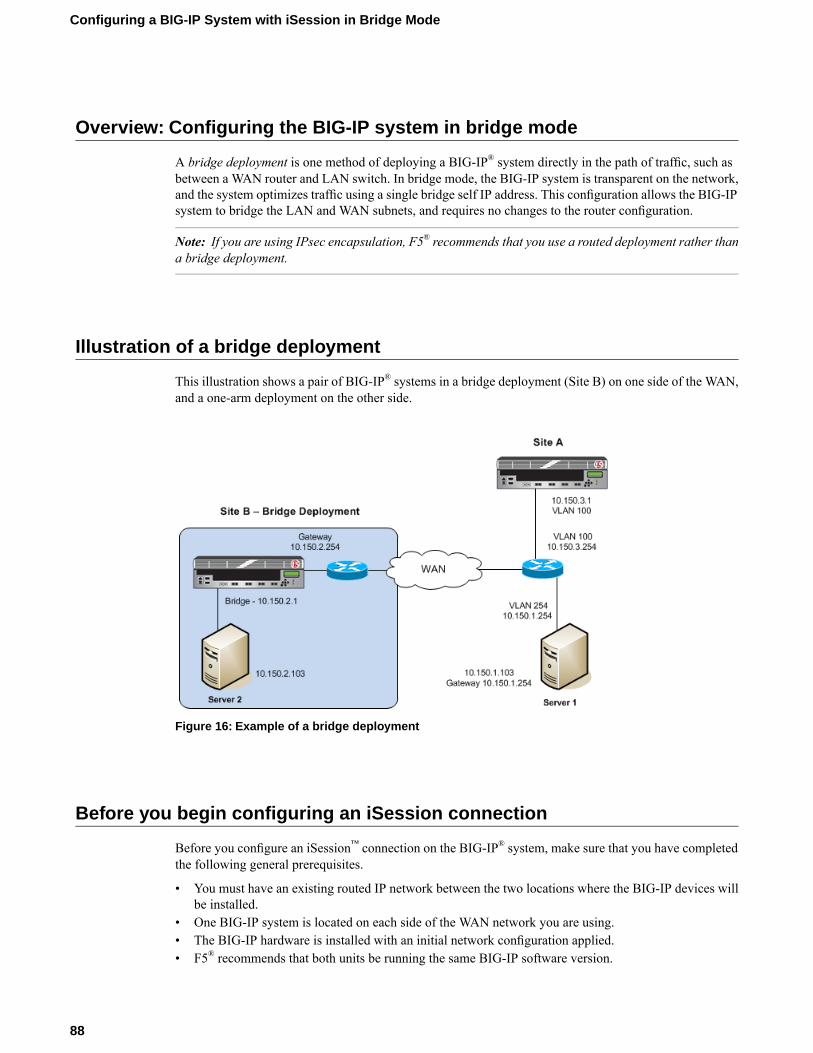
Overview: Configuring the BIG-IP system in bridge mode
A bridge deployment is one method of deploying a BIG-IP® system directly in the path of traffic, such asbetween a WAN router and LAN switch. In bridge mode, the BIG-IP system is transparent on the network,and the system optimizes traffic using a single bridge self IP address. This configuration allows the BIG-IPsystem to bridge the LAN and WAN subnets, and requires no changes to the router configuration.
Note: If you are using IPsec encapsulation, F5® recommends that you use a routed deployment rather thana bridge deployment.
Illustration of a bridge deployment
This illustration shows a pair of BIG-IP® systems in a bridge deployment (Site B) on one side of the WAN,and a one-arm deployment on the other side.
Figure 16: Example of a bridge deployment
Before you begin configuring an iSession connection
Before you configure an iSession™ connection on the BIG-IP® system, make sure that you have completedthe following general prerequisites.
• You must have an existing routed IP network between the two locations where the BIG-IP devices willbe installed.
• One BIG-IP system is located on each side of the WAN network you are using.• The BIG-IP hardware is installed with an initial network configuration applied.• F5® recommends that both units be running the same BIG-IP software version.
88
Configuring a BIG-IP System with iSession in Bridge Mode
• The Application Acceleration Manager™ license is enabled.• Application Acceleration Manager (AAM) is provisioned at the level Nominal.• The management IP address is configured on the BIG-IP system.• You must have administrative access to both the Web management and SSH command line interfaces
on the BIG-IP system.• If there are firewalls, you must have TCP port 443 open in both directions. Optionally, you can allow
TCP port 22 for SSH access to the command line interface for configuration verification, but not foractual BIG-IP iSession traffic. After you configure the BIG-IP system, you can perform this verificationfrom the Configuration utility (Acceleration > Symmetric Optimization > Diagnostics).
Task summary
If you are configuring a BIG-IP® system in bridge mode, you configure two VLANs and a VLAN group,and then associate a self IP address with the VLAN group.
Task listCreating VLANsCreating a VLAN groupCreating a self IP address for a VLAN groupDefining a routeChecking connectivitySetting up an iSession connection using the Quick Start screenValidating iSession configurationViewing pertinent configuration details from the command line
Creating VLANs
Create VLANs for the internal and external interfaces on the BIG-IP® system.
1. On the Main tab, click Network > VLANs.The VLAN List screen opens.
2. Click Create.The New VLAN screen opens.
3. In the Name field, type lan.4. In the Tag field, type a numeric tag, from 1-4094, for the VLAN, or leave the field blank if you want
the BIG-IP system to automatically assign a VLAN tag.The VLAN tag identifies the traffic from hosts in the associated VLAN.
5. For the Interfaces setting, click an internal interface (port) in the Available list, and move the selectedinterface to the Untagged or Tagged list, depending on your network configuration.This VLAN is for the traffic that the BIG-IP system you are configuring will optimize.
6. Click Repeat.The VLAN lan is added to the VLAN list, and the New VLAN screen opens.
7. In the Name field, type wan.8. In the Tag field, type a numeric tag, from 1-4094, for the VLAN, or leave the field blank if you want
the BIG-IP system to automatically assign a VLAN tag.The VLAN tag identifies the traffic from hosts in the associated VLAN.
89
BIG-IP® Acceleration: Network Configuration
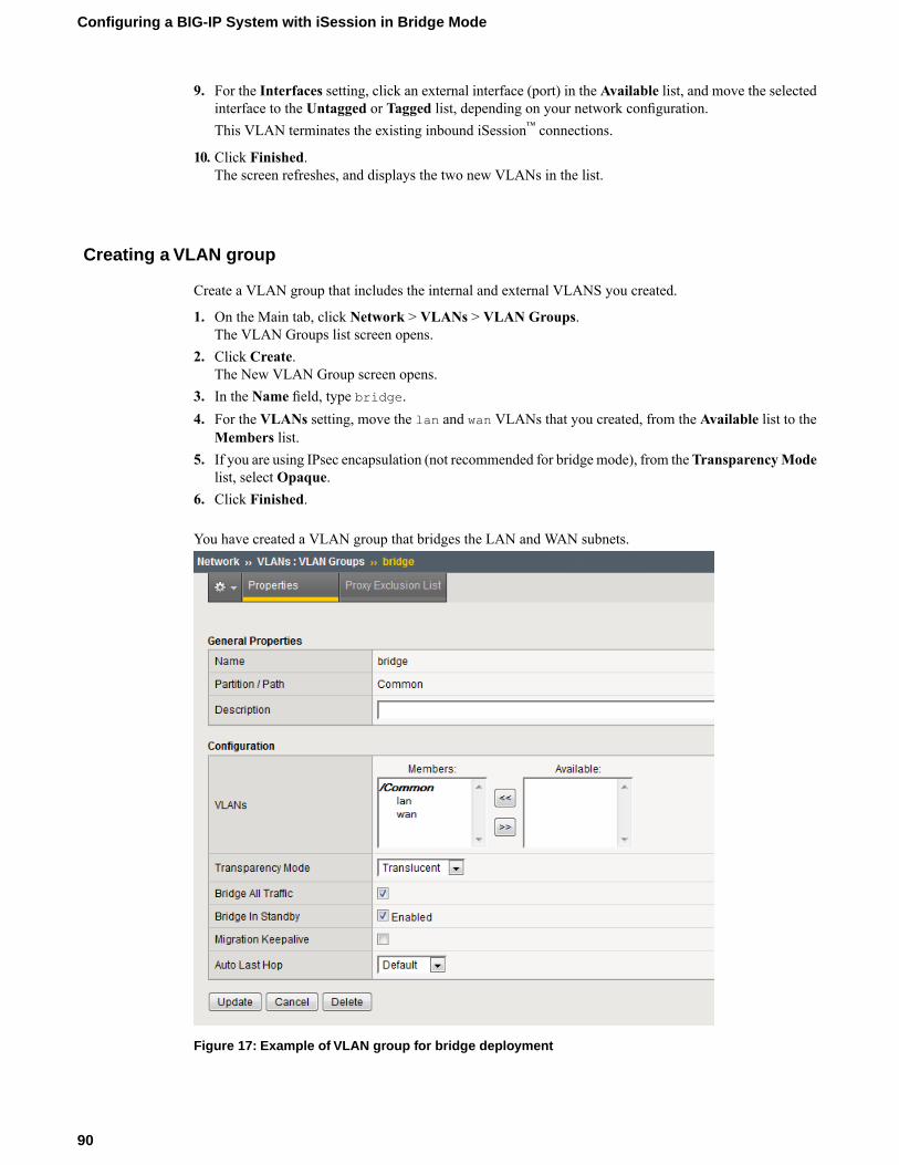
9. For the Interfaces setting, click an external interface (port) in the Available list, and move the selectedinterface to the Untagged or Tagged list, depending on your network configuration.This VLAN terminates the existing inbound iSession™ connections.
10. Click Finished.The screen refreshes, and displays the two new VLANs in the list.
Creating a VLAN group
Create a VLAN group that includes the internal and external VLANS you created.
1. On the Main tab, click Network > VLANs > VLAN Groups.The VLAN Groups list screen opens.
2. Click Create.The New VLAN Group screen opens.
3. In the Name field, type bridge.4. For the VLANs setting, move the lan and wan VLANs that you created, from the Available list to the
Members list.5. If you are using IPsec encapsulation (not recommended for bridge mode), from theTransparencyMode
list, select Opaque.6. Click Finished.
You have created a VLAN group that bridges the LAN and WAN subnets.
Figure 17: Example of VLAN group for bridge deployment
90
Configuring a BIG-IP System with iSession in Bridge Mode
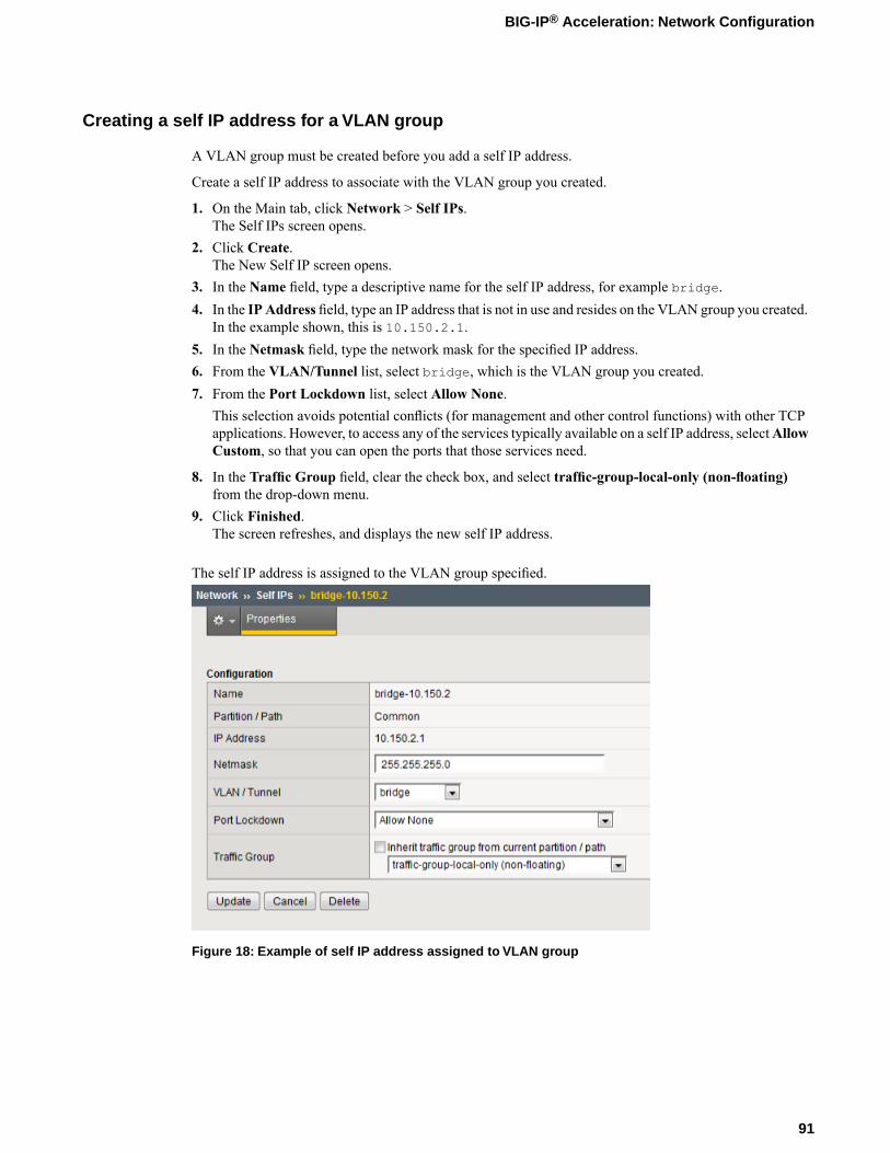
Creating a self IP address for a VLAN group
A VLAN group must be created before you add a self IP address.
Create a self IP address to associate with the VLAN group you created.
1. On the Main tab, click Network > Self IPs.The Self IPs screen opens.
2. Click Create.The New Self IP screen opens.
3. In the Name field, type a descriptive name for the self IP address, for example bridge.4. In the IP Address field, type an IP address that is not in use and resides on the VLAN group you created.
In the example shown, this is 10.150.2.1.5. In the Netmask field, type the network mask for the specified IP address.6. From the VLAN/Tunnel list, select bridge, which is the VLAN group you created.7. From the Port Lockdown list, select Allow None.
This selection avoids potential conflicts (for management and other control functions) with other TCPapplications. However, to access any of the services typically available on a self IP address, selectAllowCustom, so that you can open the ports that those services need.
8. In the Traffic Group field, clear the check box, and select traffic-group-local-only (non-floating)from the drop-down menu.
9. Click Finished.The screen refreshes, and displays the new self IP address.
The self IP address is assigned to the VLAN group specified.
Figure 18: Example of self IP address assigned to VLAN group
91
BIG-IP® Acceleration: Network Configuration
Defining a route
You must define a route on the local BIG-IP® system for sending traffic to its destination. In the exampleshown, the route defined uses the default gateway to send traffic to the router.
1. On the Main tab, click Network > Routes.2. Click Add.
The New Route screen opens.3. In the Name field, type a name for the default gateway, such as default-gateway.4. In the Destination field, type the IP address 0.0.0.0.
An IP address of 0.0.0.0 in this field indicates that the destination is a default route.
5. In the Destination field, type the destination IP address for the route.6. In the Destination field, type the 6rd IPv6 network address.7. In the Netmask field, type 0.0.0.0, the network mask for the default route.8. From the Resource list, select Use Gateway.
The gateway represents a next-hop or last-hop address in the route.
9. For the Gateway Address setting, select IP Address and type the IP address of the gateway.
Checking connectivity
Important: Use this task as a checkpoint before proceeding with iSession™setup.
You can verify connectivity from the command-line interface.
1. Ping the gateway using the command-line access to the BIG-IP® system.2. Ping end-to-end across the WAN. In the example shown, this is between Server 1 and Server 2.3. Initiate a TCP file transfer between Server 1 and Server 2.
Setting up an iSession connection using the Quick Start screen
You cannot view the Quick Start screen until you have defined at least one VLAN and at least one self IPon a configured BIG-IP® system that is provisioned for acceleration.
Use the Quick Start screen to quickly set up symmetric optimization on a single screen of the BIG-IP systemusing the default settings. To optimize WAN traffic, you must configure symmetric optimization on bothsides of the WAN.
1. On the Main tab, click Acceleration > Quick Start > Symmetric Properties.2. In theWAN Self IP Address field, type the local endpoint IP address, if it is not already displayed.
This IP address must be in the same subnet as a self IP address on the BIG-IP system, and to make surethat dynamic discovery properly detects this endpoint, the IP address must be the same as a self IPaddress on the BIG-IP system.
3. Verify that the Discovery setting is set to Enabled.If you disable theDiscovery setting, or discovery fails, youmust manually configure any remote endpointsand advertised routes.
92
Configuring a BIG-IP System with iSession in Bridge Mode
4. Specify the VLANs on which the virtual servers on this system receive incoming traffic.DescriptionOption
Select the VLANs that receive incoming LAN traffic destined for theWAN.
LAN VLANs
Select the VLANs that receive traffic from the WAN through aniSession™ connection.
WAN VLANs
5. In the Authentication area, for the Outbound iSession to WAN setting, select the SSL profile to usefor all encrypted outbound iSession connections.To get WAN optimization up and running, you can use the default selection serverssl, but you need tocustomize this profile for your production environment.
6. For the Inbound iSession from WAN setting, leave the default selection wom-default-clientssl orselect another SSL profile for which the Non-SSL Connections setting is enabled.
7. In the IP Encapsulation area, from the IP Encapsulation Type list, select the encapsulation type, if any,for outbound iSession traffic.a) If you select FEC, select a FEC profile from the FEC Profile list that appears, or retain the default,
default-ipsec-policy-isession.b) If you select IPsec, select an IPsec policy from the IPSEC Policy list that appears, or retain the
default, default-ipsec-policy-isession.c) If you select IPIP, the system uses the IP over IP tunneling protocol, and no additional encapsulation
setting is necessary.d) If you selectGRE, select a GRE profile from theGRE Profile list that appears, or retain the default,
gre.
8. Click Apply.
This example shows a completed Quick Start screen.
93
BIG-IP® Acceleration: Network Configuration

Figure 19: Example of completed Quick Start screen
To complete the setup, repeat this task on the BIG-IP system on the other side of the WAN. After youconfigure the iSession™ endpoints, use an iApp template to select the application traffic for optimization.Click Acceleration > Quick Start > Deploy Applications. Click Create, from the Template list selectf5.replication, and follow the online instructions.
Validating iSession configuration
At this point, you have finished configuring the iSession™ connection on BIG-IP® systems at opposite sidesof the WAN, and the systems have discovered their remote endpoints.
Important: Use this task as a checkpoint to allow for troubleshooting before you complete the setup.
You can validate the configuration using the browser and command-line interfaces.
1. Run diagnostics to verify the configuration.a) On the Main tab, click Acceleration > Symmetric Optimization > Diagnostics.b) Next to Diagnose WOM Configuration, click Run.c) Correct any configuration errors as indicated on the screen.
2. Transfer data between the servers at the two sites, and verify that the transfer was successful.
94
Configuring a BIG-IP System with iSession in Bridge Mode
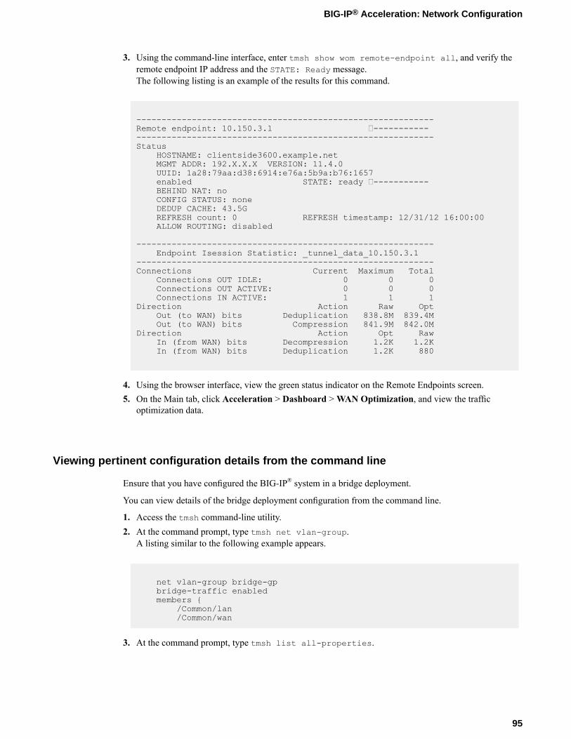
3. Using the command-line interface, enter tmsh show wom remote-endpoint all, and verify theremote endpoint IP address and the STATE: Ready message.The following listing is an example of the results for this command.
-----------------------------------------------------------Remote endpoint: 10.150.3.1 ----------------------------------------------------------------------Status
HOSTNAME: clientside3600.example.netMGMT ADDR: 192.X.X.X VERSION: 11.4.0UUID: 1a28:79aa:d38:6914:e76a:5b9a:b76:1657enabled STATE: ready -----------BEHIND NAT: noCONFIG STATUS: noneDEDUP CACHE: 43.5GREFRESH count: 0 REFRESH timestamp: 12/31/12 16:00:00ALLOW ROUTING: disabled
-----------------------------------------------------------Endpoint Isession Statistic: _tunnel_data_10.150.3.1
-----------------------------------------------------------Connections Current Maximum Total
Connections OUT IDLE: 0 0 0Connections OUT ACTIVE: 0 0 0Connections IN ACTIVE: 1 1 1
Direction Action Raw OptOut (to WAN) bits Deduplication 838.8M 839.4MOut (to WAN) bits Compression 841.9M 842.0M
Direction Action Opt RawIn (from WAN) bits Decompression 1.2K 1.2KIn (from WAN) bits Deduplication 1.2K 880
4. Using the browser interface, view the green status indicator on the Remote Endpoints screen.5. On the Main tab, click Acceleration > Dashboard >WAN Optimization, and view the traffic
optimization data.
Viewing pertinent configuration details from the command line
Ensure that you have configured the BIG-IP® system in a bridge deployment.
You can view details of the bridge deployment configuration from the command line.
1. Access the tmsh command-line utility.2. At the command prompt, type tmsh net vlan-group.
A listing similar to the following example appears.
net vlan-group bridge-gpbridge-traffic enabledmembers {
/Common/lan/Common/wan
3. At the command prompt, type tmsh list all-properties.
95
BIG-IP® Acceleration: Network Configuration

The following listing is an example of the pertinent information displayed on the command line for abridge configuration.
ltm profile tcp wom-tcp-lan-optimized {abc enabledack-on-push enabledapp-service noneclose-wait-timeout 5cmetrics-cache disabledcongestion-control high-speeddefaults-from tcp-lan-optimizeddeferred-accept disableddelay-window-control disableddelayed-acks disableddescription nonedsack disabledecn disabledfin-wait-timeout 5idle-timeout 600init-cwnd 0init-rwnd 0ip-tos-to-client 0keep-alive-interval 1800limited-transmit enabledlink-qos-to-client 0max-retrans 8md5-signature disabledmd5-signature-passphrase nonenagle enabledpartition Commonpkt-loss-ignore-burst 0pkt-loss-ignore-rate 0proxy-buffer-high 1228800proxy-buffer-low 98304proxy-mss disabledproxy-options disabledreceive-window-size 65535reset-on-timeout enabledrfc1323 enabledselective-acks enabledselective-nack disabledsend-buffer-size 65535slow-start disabledsyn-max-retrans 3syn-rto-base 0tcp-options nonetime-wait-recycle enabledtime-wait-timeout 2000verified-accept disabledzero-window-timeout 20000
}ltm profile tcp wom-tcp-wan-optimized {
abc enabledack-on-push disabledapp-service noneclose-wait-timeout 5cmetrics-cache enabledcongestion-control high-speeddefaults-from tcp-wan-optimizeddeferred-accept disableddelay-window-control disableddelayed-acks disableddescription nonedsack disabledecn disabledfin-wait-timeout 5idle-timeout 600
96
Configuring a BIG-IP System with iSession in Bridge Mode
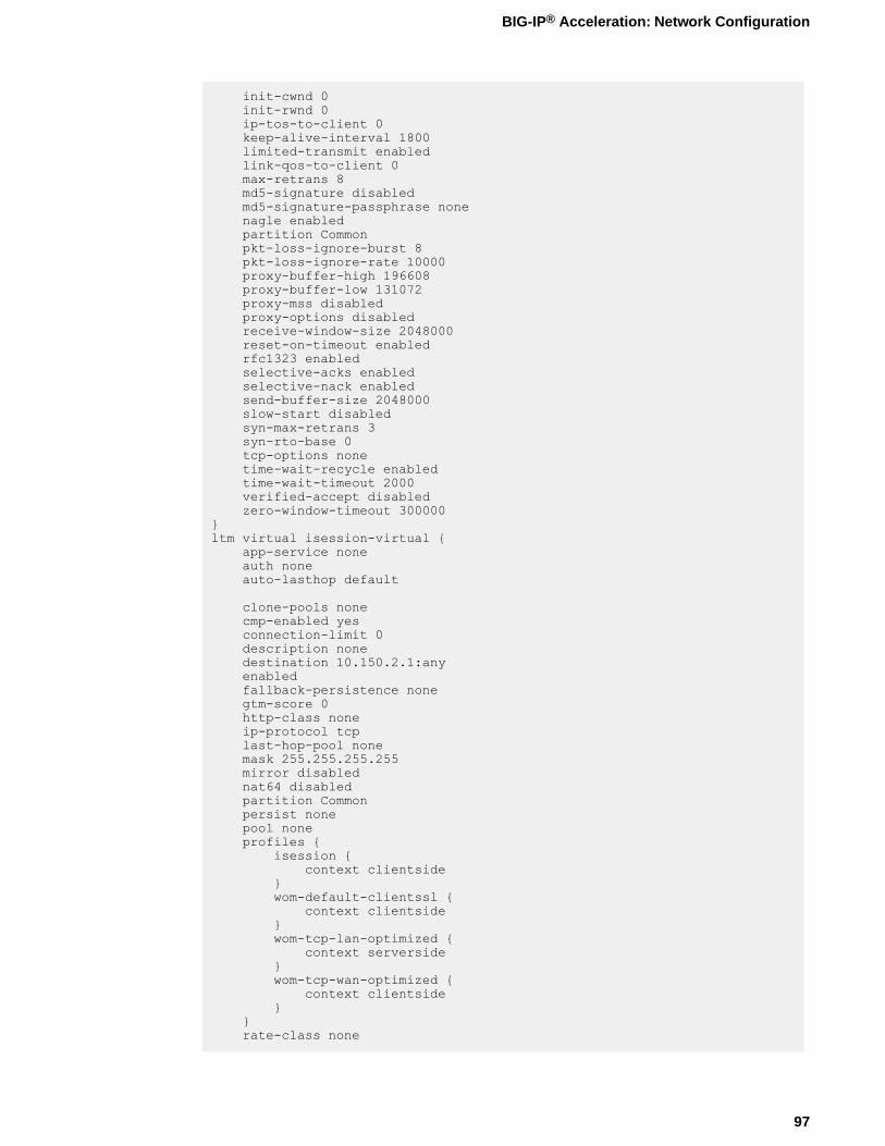
init-cwnd 0init-rwnd 0ip-tos-to-client 0keep-alive-interval 1800limited-transmit enabledlink-qos-to-client 0max-retrans 8md5-signature disabledmd5-signature-passphrase nonenagle enabledpartition Commonpkt-loss-ignore-burst 8pkt-loss-ignore-rate 10000proxy-buffer-high 196608proxy-buffer-low 131072proxy-mss disabledproxy-options disabledreceive-window-size 2048000reset-on-timeout enabledrfc1323 enabledselective-acks enabledselective-nack enabledsend-buffer-size 2048000slow-start disabledsyn-max-retrans 3syn-rto-base 0tcp-options nonetime-wait-recycle enabledtime-wait-timeout 2000verified-accept disabledzero-window-timeout 300000
}ltm virtual isession-virtual {
app-service noneauth noneauto-lasthop default
clone-pools nonecmp-enabled yesconnection-limit 0description nonedestination 10.150.2.1:anyenabledfallback-persistence nonegtm-score 0http-class noneip-protocol tcplast-hop-pool nonemask 255.255.255.255mirror disablednat64 disabledpartition Commonpersist nonepool noneprofiles {
isession {context clientside
}wom-default-clientssl {
context clientside}wom-tcp-lan-optimized {
context serverside}wom-tcp-wan-optimized {
context clientside}
}rate-class none
97
BIG-IP® Acceleration: Network Configuration

rules nonesnat nonesource-port preservetraffic-classes nonetranslate-address enabledtranslate-port disabledvlans nonevlans-disabled
}net interface 1.1 {
app-service nonedescription noneenabledflow-control tx-rxforce-gigabit-fiber disabledmac-address 0:1:d7:7d:ea:c4media nonemedia-active 1000T-FDmedia-fixed automedia-max 1000T-FDmedia-sfp auto
mtu 1500prefer-port sfpstp enabledstp-auto-edge-port enabledstp-edge-port truestp-link-type autovendor none
}net interface 1.2 {
app-service nonedescription noneenabledflow-control tx-rxforce-gigabit-fiber disabledmac-address 0:1:d7:7d:ea:c5media nonemedia-active 1000T-FDmedia-fixed automedia-max 1000T-FDmedia-sfp automtu 1500prefer-port sfpstp enabledstp-auto-edge-port enabledstp-edge-port truestp-link-type autovendor none
}net route 10.x-route {
description nonegw 10.150.2.254mtu 0network defaultpartition Common
}net self bridge-10.150.2 {
address 10.150.2.1/24allow-service noneapp-service nonedescription nonefloating disabledinherited-traffic-group falsepartition Commontraffic-group traffic-group-local-onlyunit 0vlan bridge-gp
}
98
Configuring a BIG-IP System with iSession in Bridge Mode
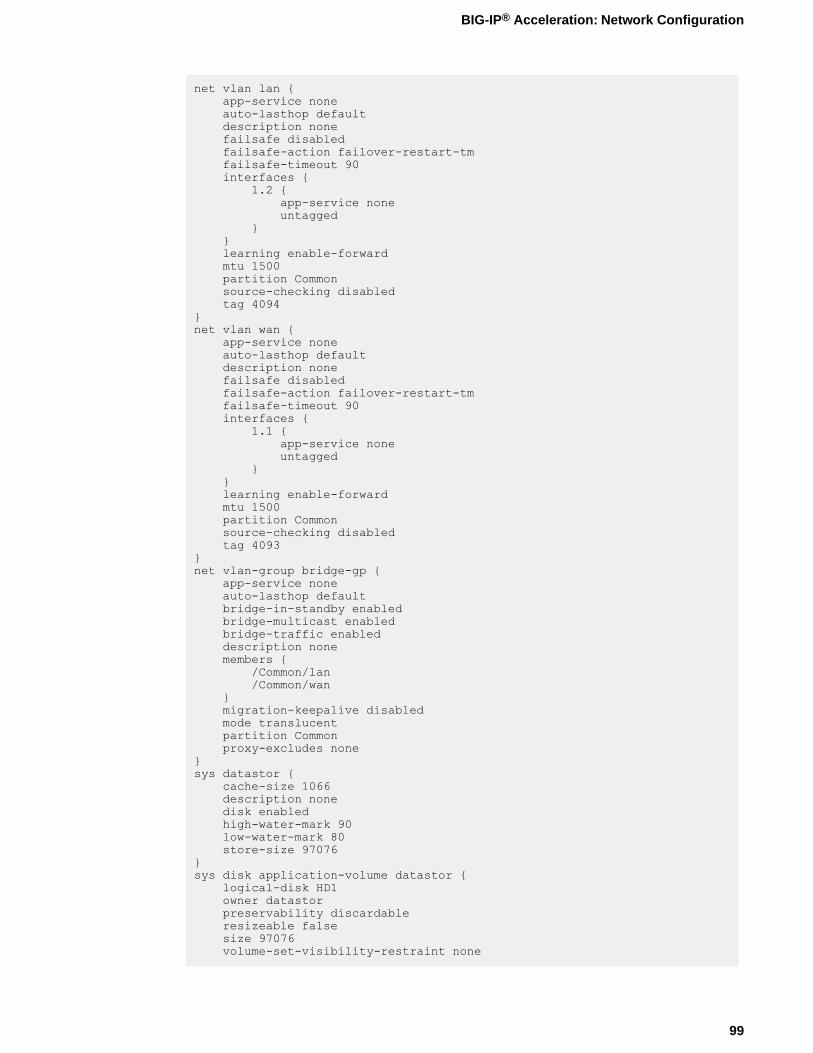
net vlan lan {app-service noneauto-lasthop defaultdescription nonefailsafe disabledfailsafe-action failover-restart-tmfailsafe-timeout 90interfaces {
1.2 {app-service noneuntagged
}}learning enable-forwardmtu 1500partition Commonsource-checking disabledtag 4094
}net vlan wan {
app-service noneauto-lasthop defaultdescription nonefailsafe disabledfailsafe-action failover-restart-tmfailsafe-timeout 90interfaces {
1.1 {app-service noneuntagged
}}learning enable-forwardmtu 1500partition Commonsource-checking disabledtag 4093
}net vlan-group bridge-gp {
app-service noneauto-lasthop defaultbridge-in-standby enabledbridge-multicast enabledbridge-traffic enableddescription nonemembers {
/Common/lan/Common/wan
}migration-keepalive disabledmode translucentpartition Commonproxy-excludes none
}sys datastor {
cache-size 1066description nonedisk enabledhigh-water-mark 90low-water-mark 80store-size 97076
}sys disk application-volume datastor {
logical-disk HD1owner datastorpreservability discardableresizeable falsesize 97076volume-set-visibility-restraint none
99
BIG-IP® Acceleration: Network Configuration

}sys management-route default {
app-service nonedescription nonegateway 192.31.3.129mtu 1500network default
}
sys provision wom {app-service nonecpu-ratio 0description nonedisk-ratio 0level nominalmemory-ratio 0
}sys provision woml {
app-service nonecpu-ratio 0description nonedisk-ratio 0level nonememory-ratio 0
}wom advertised-route 10.150.2.0-24 {
app-service nonedescription nonedest 10.150.2.0/24include enabledlabel nonemetric 0origin manually-saved
}wom deduplication {
description nonedictionary-size 256disk-cache-size 97076enabledmax-endpoint-count 1
wom endpoint-discovery {auto-save enableddescription nonediscoverable enableddiscovered-endpoint enabledicmp-max-requests 1024icmp-min-backoff 5icmp-num-retries 10max-endpoint-count 0mode enable-all
}wom local-endpoint {
addresses { 10.150.2.1 }allow-nat enableddescription noneendpoint enabledip-encap-mtu 0ip-encap-profile { "" }ip-encap-type noneno-route passthruserver-ssl serversslsnat nonetunnel-port https
}wom profile isession isession-http {
adaptive-compression enabledapp-service nonecompression enabledcompression-codecs { deflate lzo bzip2 }
100
Configuring a BIG-IP System with iSession in Bridge Mode
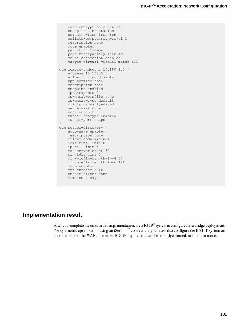
data-encryption disableddeduplication enableddefaults-from isessiondeflate-compression-level 1description nonemode enabledpartition Commonport-transparency enabledreuse-connection enabledtarget-virtual virtual-match-all
}wom remote-endpoint 10.150.3.1 {
address 10.150.3.1allow-routing disabledapp-service nonedescription noneendpoint enabledip-encap-mtu 0ip-encap-profile noneip-encap-type defaultorigin manually-savedserver-ssl nonesnat defaulttunnel-encrypt enabledtunnel-port https
}wom server-discovery {
auto-save enableddescription nonefilter-mode excludeidle-time-limit 0ip-ttl-limit 5max-server-count 50min-idle-time 0min-prefix-length-ipv4 24min-prefix-length-ipv6 128mode enabledrtt-threshold 10subnet-filter nonetime-unit days
}
Implementation result
After you complete the tasks in this implementation, the BIG-IP® system is configured in a bridge deployment.For symmetric optimization using an iSession™ connection, you must also configure the BIG-IP system onthe other side of the WAN. The other BIG-IP deployment can be in bridge, routed, or one-arm mode.
101
BIG-IP® Acceleration: Network Configuration


Chapter
9Configuring a BIG-IP System with iSession in Routed Mode
• Overview: Configuring the BIG-IP system inrouted mode
• Illustration of a routed deployment• About symmetric optimization using iSession
on BIG-IP systems• Before you begin configuring an iSession
connection• Task summary• Implementation result
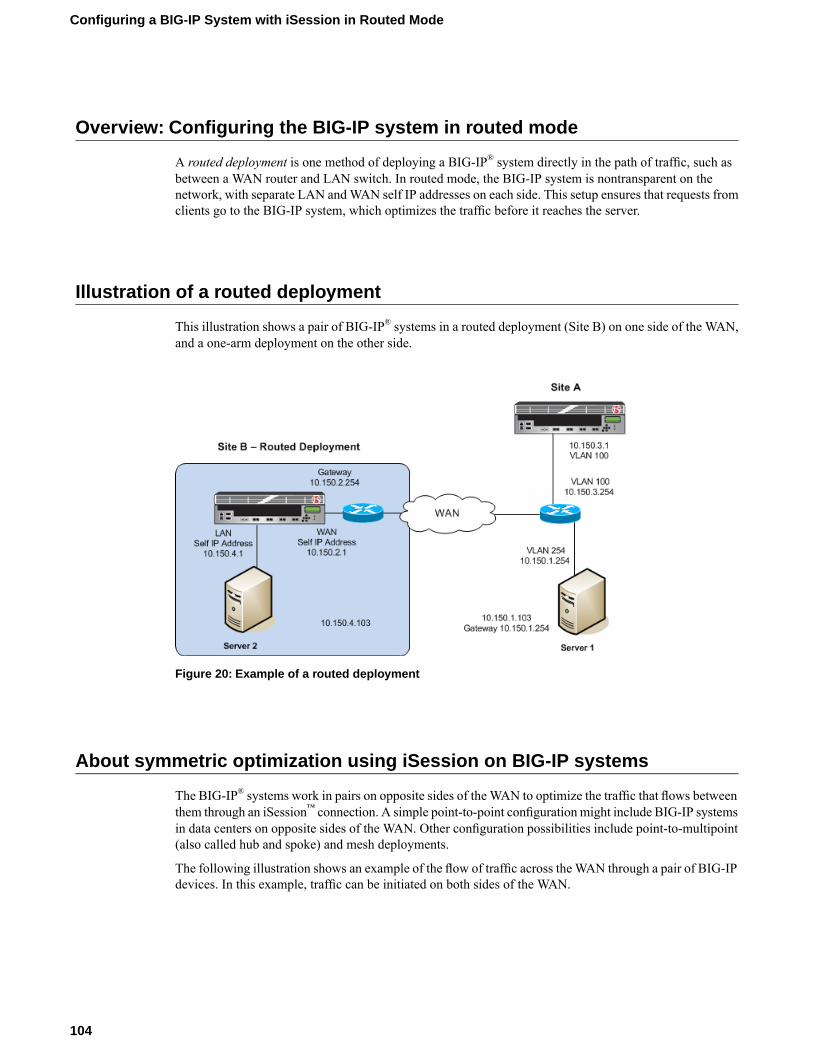
Overview: Configuring the BIG-IP system in routed mode
A routed deployment is one method of deploying a BIG-IP® system directly in the path of traffic, such asbetween a WAN router and LAN switch. In routed mode, the BIG-IP system is nontransparent on thenetwork, with separate LAN andWAN self IP addresses on each side. This setup ensures that requests fromclients go to the BIG-IP system, which optimizes the traffic before it reaches the server.
Illustration of a routed deployment
This illustration shows a pair of BIG-IP® systems in a routed deployment (Site B) on one side of the WAN,and a one-arm deployment on the other side.
Figure 20: Example of a routed deployment
About symmetric optimization using iSession on BIG-IP systems
The BIG-IP® systems work in pairs on opposite sides of the WAN to optimize the traffic that flows betweenthem through an iSession™ connection. A simple point-to-point configuration might include BIG-IP systemsin data centers on opposite sides of the WAN. Other configuration possibilities include point-to-multipoint(also called hub and spoke) and mesh deployments.
The following illustration shows an example of the flow of traffic across theWAN through a pair of BIG-IPdevices. In this example, traffic can be initiated on both sides of the WAN.
104
Configuring a BIG-IP System with iSession in Routed Mode
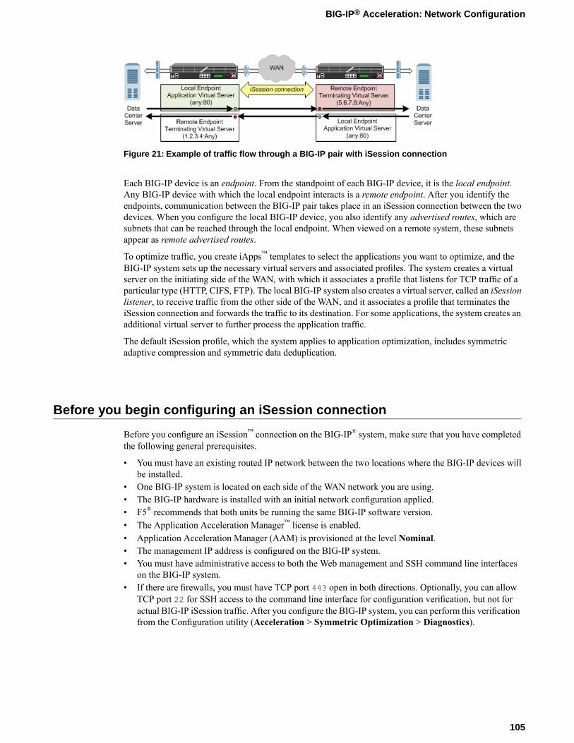
Figure 21: Example of traffic flow through a BIG-IP pair with iSession connection
Each BIG-IP device is an endpoint. From the standpoint of each BIG-IP device, it is the local endpoint.Any BIG-IP device with which the local endpoint interacts is a remote endpoint. After you identify theendpoints, communication between the BIG-IP pair takes place in an iSession connection between the twodevices. When you configure the local BIG-IP device, you also identify any advertised routes, which aresubnets that can be reached through the local endpoint. When viewed on a remote system, these subnetsappear as remote advertised routes.
To optimize traffic, you create iApps™ templates to select the applications you want to optimize, and theBIG-IP system sets up the necessary virtual servers and associated profiles. The system creates a virtualserver on the initiating side of the WAN, with which it associates a profile that listens for TCP traffic of aparticular type (HTTP, CIFS, FTP). The local BIG-IP system also creates a virtual server, called an iSessionlistener, to receive traffic from the other side of the WAN, and it associates a profile that terminates theiSession connection and forwards the traffic to its destination. For some applications, the system creates anadditional virtual server to further process the application traffic.
The default iSession profile, which the system applies to application optimization, includes symmetricadaptive compression and symmetric data deduplication.
Before you begin configuring an iSession connection
Before you configure an iSession™ connection on the BIG-IP® system, make sure that you have completedthe following general prerequisites.
• You must have an existing routed IP network between the two locations where the BIG-IP devices willbe installed.
• One BIG-IP system is located on each side of the WAN network you are using.• The BIG-IP hardware is installed with an initial network configuration applied.• F5® recommends that both units be running the same BIG-IP software version.• The Application Acceleration Manager™ license is enabled.• Application Acceleration Manager (AAM) is provisioned at the level Nominal.• The management IP address is configured on the BIG-IP system.• You must have administrative access to both the Web management and SSH command line interfaces
on the BIG-IP system.• If there are firewalls, you must have TCP port 443 open in both directions. Optionally, you can allow
TCP port 22 for SSH access to the command line interface for configuration verification, but not foractual BIG-IP iSession traffic. After you configure the BIG-IP system, you can perform this verificationfrom the Configuration utility (Acceleration > Symmetric Optimization > Diagnostics).
105
BIG-IP® Acceleration: Network Configuration
Task summary
If you are configuring a BIG-IP® system in routed mode, you configure separate self IP addresses for theinternal and external interfaces. Also, you need to create a passthrough virtual server that you can use toverify the connection before you try to optimize traffic.
Note: Make sure that you associate the LAN and WAN VLANs with the appropriate interfaces (ports).
Task listCreating VLANsCreating self IP addresses for internal and external VLANsCreating a default gatewayCreating a passthrough virtual serverChecking connectivitySetting up an iSession connection using the Quick Start screenValidating iSession configurationViewing pertinent configuration details from the command line
Creating VLANs
Create VLANs for the internal and external interfaces on the BIG-IP® system.
1. On the Main tab, click Network > VLANs.The VLAN List screen opens.
2. Click Create.The New VLAN screen opens.
3. In the Name field, type lan.4. In the Tag field, type a numeric tag, from 1-4094, for the VLAN, or leave the field blank if you want
the BIG-IP system to automatically assign a VLAN tag.The VLAN tag identifies the traffic from hosts in the associated VLAN.
5. For the Interfaces setting, click an internal interface (port) in the Available list, and move the selectedinterface to the Untagged or Tagged list, depending on your network configuration.This VLAN is for the traffic that the BIG-IP system you are configuring will optimize.
6. Click Repeat.The VLAN lan is added to the VLAN list, and the New VLAN screen opens.
7. In the Name field, type wan.8. In the Tag field, type a numeric tag, from 1-4094, for the VLAN, or leave the field blank if you want
the BIG-IP system to automatically assign a VLAN tag.The VLAN tag identifies the traffic from hosts in the associated VLAN.
9. For the Interfaces setting, click an external interface (port) in the Available list, and move the selectedinterface to the Untagged or Tagged list, depending on your network configuration.This VLAN terminates the existing inbound iSession™ connections.
10. Click Finished.The screen refreshes, and displays the two new VLANs in the list.
106
Configuring a BIG-IP System with iSession in Routed Mode

Creating self IP addresses for internal and external VLANs
VLANs must exist on the BIG-IP® system for both internal and external interfaces (ports).
Self IP addresses enable the BIG-IP system, and other devices on the network, to route application trafficthrough the associated VLAN. Create self IP addresses on the BIG-IP device to assign to the internal andexternal VLANs.
1. On the Main tab, click Network > Self IPs.The Self IPs screen opens.
2. Click Create.The New Self IP screen opens.
3. In the Name field, type a descriptive name for the self IP, for example lan.4. In the IP Address field, type an IP address that is not in use and resides on the internal VLAN.5. In the Netmask field, type the network mask for the specified IP address.6. From the VLAN/Tunnel list, select lan, which is the VLAN group you created.7. In the Traffic Group field, clear the check box, and select traffic-group-local-only (non-floating)
from the drop-down menu.8. Click Repeat.
The screen refreshes, and displays a new self IP screen.9. In the Name field, type a descriptive name for the self IP, for example wan.10. In the IP Address field, type an IP address that is not in use and resides on the external VLAN.11. In the Netmask field, type the network mask for the specified IP address.12. From the VLAN/Tunnel list, select the external VLAN, for example, wan.13. From the Port Lockdown list, select Allow None.
This selection avoids potential conflicts (for management and other control functions) with other TCPapplications. However, to access any of the services typically available on a self IP address, selectAllowCustom, so that you can open the ports that those services need.
14. In the Traffic Group field, clear the check box, and select traffic-group-local-only (non-floating)from the drop-down menu.
15. Click Finished.The screen refreshes, and displays the new self IP address.
Creating a default gateway
You must define a route on the local BIG-IP® system for sending traffic to its destination. In the exampleshown, the route defined uses the default gateway to send traffic to the router.
1. On the Main tab, click Network > Routes.2. Click Add.
The New Route screen opens.3. In the Name field, type a name for the default gateway, such as default-gateway.4. In the Destination field, type the IP address 0.0.0.0.
An IP address of 0.0.0.0 in this field indicates that the destination is a default route.
5. In the Destination field, type the destination IP address for the route.6. In the Destination field, type the 6rd IPv6 network address.
107
BIG-IP® Acceleration: Network Configuration
7. In the Netmask field, type 0.0.0.0, the network mask for the default route.8. From the Resource list, select Use Gateway.
The gateway represents a next-hop or last-hop address in the route.
9. For the Gateway Address setting, select IP Address and type the IP address of the gateway.
Creating a passthrough virtual server
A virtual server represents a destination IP address for application traffic. You can use a passthrough virtualserver to verify a connection before trying to optimize traffic using an iSession™ connection.
1. On the Main tab, click Local Traffic > Virtual Servers.The Virtual Server List screen opens.
2. Click the Create button.The New Virtual Server screen opens.
3. In the Name field, type a unique name for the virtual server.4. For the Destination setting:
a) For Type, select Network.b) In the Address field, type the IP address 0.0.0.0.c) In theMask field, type the netmask 0.0.0.0.
5. From the Service Port list, select *All Ports.6. For the State setting, retain the default value, Enabled.7. In the Configuration area of the screen, from the Type list, select Forwarding (IP).8. From the Protocol list, select *All Protocols.9. From the VLAN Traffic and Tunnel Traffic list, select All VLANs and Tunnels.10. Click Finished.
The purpose of this virtual server is to forward all IP traffic. You will create a separate virtual server foroptimized trafficwhen you configure an iSession connection and deploy applications using iApps™ templates.
Checking connectivity
Important: Use this task as a checkpoint before proceeding with iSession™setup.
You can verify connectivity from the command-line interface.
1. Ping the gateway using the command-line access to the BIG-IP® system.2. Ping end-to-end across the WAN. In the example shown, this is between Server 1 and Server 2.3. Initiate a TCP file transfer between Server 1 and Server 2.
Setting up an iSession connection using the Quick Start screen
You cannot view the Quick Start screen until you have defined at least one VLAN and at least one self IPon a configured BIG-IP® system that is provisioned for acceleration.
108
Configuring a BIG-IP System with iSession in Routed Mode

Use the Quick Start screen to quickly set up symmetric optimization on a single screen of the BIG-IP systemusing the default settings. To optimize WAN traffic, you must configure symmetric optimization on bothsides of the WAN.
1. On the Main tab, click Acceleration > Quick Start > Symmetric Properties.2. In theWAN Self IP Address field, type the local endpoint IP address, if it is not already displayed.
This IP address must be in the same subnet as a self IP address on the BIG-IP system, and to make surethat dynamic discovery properly detects this endpoint, the IP address must be the same as a self IPaddress on the BIG-IP system.
3. Verify that the Discovery setting is set to Enabled.If you disable theDiscovery setting, or discovery fails, youmust manually configure any remote endpointsand advertised routes.
4. Specify the VLANs on which the virtual servers on this system receive incoming traffic.DescriptionOption
Select the VLANs that receive incoming LAN traffic destined for theWAN.
LAN VLANs
Select the VLANs that receive traffic from the WAN through aniSession™ connection.
WAN VLANs
5. In the Authentication area, for the Outbound iSession to WAN setting, select the SSL profile to usefor all encrypted outbound iSession connections.To get WAN optimization up and running, you can use the default selection serverssl, but you need tocustomize this profile for your production environment.
6. For the Inbound iSession from WAN setting, leave the default selection wom-default-clientssl orselect another SSL profile for which the Non-SSL Connections setting is enabled.
7. In the IP Encapsulation area, from the IP Encapsulation Type list, select the encapsulation type, if any,for outbound iSession traffic.a) If you select FEC, select a FEC profile from the FEC Profile list that appears, or retain the default,
default-ipsec-policy-isession.b) If you select IPsec, select an IPsec policy from the IPSEC Policy list that appears, or retain the
default, default-ipsec-policy-isession.c) If you select IPIP, the system uses the IP over IP tunneling protocol, and no additional encapsulation
setting is necessary.d) If you selectGRE, select a GRE profile from theGRE Profile list that appears, or retain the default,
gre.
8. Click Apply.
This example shows a completed Quick Start screen.
109
BIG-IP® Acceleration: Network Configuration
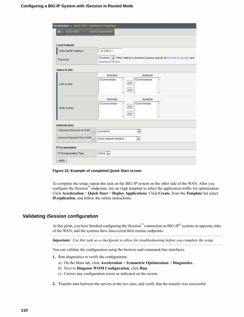
Figure 22: Example of completed Quick Start screen
To complete the setup, repeat this task on the BIG-IP system on the other side of the WAN. After youconfigure the iSession™ endpoints, use an iApp template to select the application traffic for optimization.Click Acceleration > Quick Start > Deploy Applications. Click Create, from the Template list selectf5.replication, and follow the online instructions.
Validating iSession configuration
At this point, you have finished configuring the iSession™ connection on BIG-IP® systems at opposite sidesof the WAN, and the systems have discovered their remote endpoints.
Important: Use this task as a checkpoint to allow for troubleshooting before you complete the setup.
You can validate the configuration using the browser and command-line interfaces.
1. Run diagnostics to verify the configuration.a) On the Main tab, click Acceleration > Symmetric Optimization > Diagnostics.b) Next to Diagnose WOM Configuration, click Run.c) Correct any configuration errors as indicated on the screen.
2. Transfer data between the servers at the two sites, and verify that the transfer was successful.
110
Configuring a BIG-IP System with iSession in Routed Mode
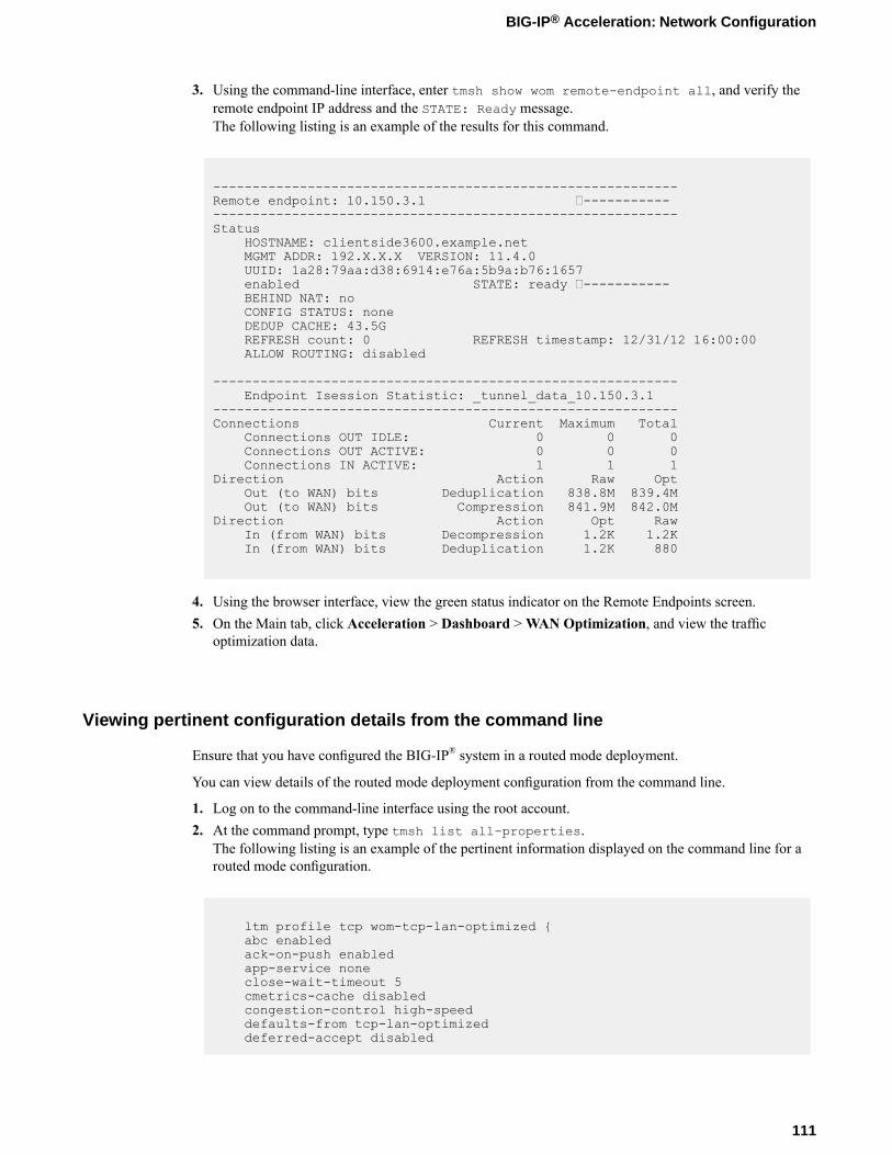
3. Using the command-line interface, enter tmsh show wom remote-endpoint all, and verify theremote endpoint IP address and the STATE: Ready message.The following listing is an example of the results for this command.
-----------------------------------------------------------Remote endpoint: 10.150.3.1 ----------------------------------------------------------------------Status
HOSTNAME: clientside3600.example.netMGMT ADDR: 192.X.X.X VERSION: 11.4.0UUID: 1a28:79aa:d38:6914:e76a:5b9a:b76:1657enabled STATE: ready -----------BEHIND NAT: noCONFIG STATUS: noneDEDUP CACHE: 43.5GREFRESH count: 0 REFRESH timestamp: 12/31/12 16:00:00ALLOW ROUTING: disabled
-----------------------------------------------------------Endpoint Isession Statistic: _tunnel_data_10.150.3.1
-----------------------------------------------------------Connections Current Maximum Total
Connections OUT IDLE: 0 0 0Connections OUT ACTIVE: 0 0 0Connections IN ACTIVE: 1 1 1
Direction Action Raw OptOut (to WAN) bits Deduplication 838.8M 839.4MOut (to WAN) bits Compression 841.9M 842.0M
Direction Action Opt RawIn (from WAN) bits Decompression 1.2K 1.2KIn (from WAN) bits Deduplication 1.2K 880
4. Using the browser interface, view the green status indicator on the Remote Endpoints screen.5. On the Main tab, click Acceleration > Dashboard >WAN Optimization, and view the traffic
optimization data.
Viewing pertinent configuration details from the command line
Ensure that you have configured the BIG-IP® system in a routed mode deployment.
You can view details of the routed mode deployment configuration from the command line.
1. Log on to the command-line interface using the root account.2. At the command prompt, type tmsh list all-properties.
The following listing is an example of the pertinent information displayed on the command line for arouted mode configuration.
ltm profile tcp wom-tcp-lan-optimized {abc enabledack-on-push enabledapp-service noneclose-wait-timeout 5cmetrics-cache disabledcongestion-control high-speeddefaults-from tcp-lan-optimizeddeferred-accept disabled
111
BIG-IP® Acceleration: Network Configuration

delay-window-control disableddelayed-acks disableddescription nonedsack disabledecn disabledfin-wait-timeout 5idle-timeout 600init-cwnd 0init-rwnd 0ip-tos-to-client 0keep-alive-interval 1800limited-transmit enabledlink-qos-to-client 0max-retrans 8md5-signature disabledmd5-signature-passphrase nonenagle enabledpartition Commonpkt-loss-ignore-burst 0pkt-loss-ignore-rate 0proxy-buffer-high 1228800proxy-buffer-low 98304proxy-mss disabledproxy-options disabledreceive-window-size 65535reset-on-timeout enabledrfc1323 enabledselective-acks enabledselective-nack disabledsend-buffer-size 65535slow-start disabledsyn-max-retrans 3syn-rto-base 0tcp-options nonetime-wait-recycle enabledtime-wait-timeout 2000verified-accept disabledzero-window-timeout 20000
}ltm profile tcp wom-tcp-wan-optimized {
abc enabledack-on-push disabledapp-service noneclose-wait-timeout 5cmetrics-cache enabledcongestion-control high-speeddefaults-from tcp-wan-optimizeddeferred-accept disableddelay-window-control disableddelayed-acks disableddescription nonedsack disabledecn disabledfin-wait-timeout 5idle-timeout 600init-cwnd 0init-rwnd 0ip-tos-to-client 0keep-alive-interval 1800limited-transmit enabledlink-qos-to-client 0max-retrans 8md5-signature disabledmd5-signature-passphrase nonenagle enabledpartition Commonpkt-loss-ignore-burst 8pkt-loss-ignore-rate 10000proxy-buffer-high 196608
112
Configuring a BIG-IP System with iSession in Routed Mode

proxy-buffer-low 131072proxy-mss disabledproxy-options disabledreceive-window-size 2048000reset-on-timeout enabledrfc1323 enabledselective-acks enabledselective-nack enabledsend-buffer-size 2048000slow-start disabledsyn-max-retrans 3syn-rto-base 0tcp-options nonetime-wait-recycle enabledtime-wait-timeout 2000verified-accept disabledzero-window-timeout 300000
}ltm virtual isession-virtual {
app-service noneauth noneauto-lasthop defaultclone-pools nonecmp-enabled yesconnection-limit 0description nonedestination 10.150.2.1:anyenabledfallback-persistence nonegtm-score 0http-class noneip-protocol tcplast-hop-pool nonemask 255.255.255.255mirror disablednat64 disabledpartition Commonpersist nonepool noneprofiles {
isession {context clientside
}wom-default-clientssl {
context clientside}wom-tcp-lan-optimized {
context serverside}wom-tcp-wan-optimized {
context clientside}
}rate-class nonerules nonesnat nonesource-port preservetraffic-classes nonetranslate-address enabledtranslate-port disabledvlans nonevlans-disabled
}ltm virtual pass-through {
app-service noneauth noneauto-lasthop defaultclone-pools nonecmp-enabled yes
113
BIG-IP® Acceleration: Network Configuration

connection-limit 0description nonedestination 0.0.0.0:anyenabledfallback-persistence nonegtm-score 0http-class noneip-forwardip-protocol anylast-hop-pool nonemask anymirror disablednat64 disabledpartition Commonpersist nonepool noneprofiles {
fastL4 {context all
}}rate-class nonerules nonesnat nonesource-port preservetraffic-classes nonetranslate-address disabledtranslate-port disabledvlans nonevlans-disabled
}net interface 1.1 {
app-service nonedescription noneenabledflow-control tx-rxforce-gigabit-fiber disabledmac-address 0:1:d7:b3:d5:c4media nonemedia-active 1000T-FDmedia-fixed automedia-max 1000T-FDmedia-sfp automtu 1500prefer-port sfpstp enabledstp-auto-edge-port enabledstp-edge-port truestp-link-type autovendor none
}net interface 1.2 {
app-service nonedescription noneenabledflow-control tx-rxforce-gigabit-fiber disabledmac-address 0:1:d7:b3:d5:c5media nonemedia-active nonemedia-fixed automedia-max 1000T-FDmedia-sfp automtu 1500prefer-port sfpstp enabledstp-auto-edge-port enabledstp-edge-port truestp-link-type auto
114
Configuring a BIG-IP System with iSession in Routed Mode

vendor none}net route dgw {
description nonegw 10.150.2.254mtu 0network defaultpartition Common
}net self WAN-side {
address 10.150.2.1/24allow-service noneapp-service nonedescription nonefloating disabledinherited-traffic-group falsepartition Commontraffic-group traffic-group-local-onlyunit 0vlan WAN
}net self Lan-side {
address 10.150.4.1/24allow-service {
default}app-service nonedescription nonefloating disabledinherited-traffic-group falsepartition Commontraffic-group traffic-group-local-onlyunit 0vlan LAN
}net vlan LAN {
app-service noneauto-lasthop defaultdescription nonefailsafe disabledfailsafe-action failover-restart-tmfailsafe-timeout 90interfaces {
1.6 {app-service noneuntagged
}}learning enable-forwardmac-masquerade nonemtu 1500partition Commonsource-checking disabledtag 4093
}net vlan WAN {
app-service noneauto-lasthop defaultdescription nonefailsafe disabledfailsafe-action failover-restart-tmfailsafe-timeout 90interfaces {
1.1 {app-service noneuntagged
}}learning enable-forward
115
BIG-IP® Acceleration: Network Configuration

mac-masquerade nonemtu 1500partition Commonsource-checking disabledtag 4094
}sys datastor {
cache-size 788description nonedisk enabledhigh-water-mark 90low-water-mark 80store-size 247580
}sys disk application-volume datastor {
logical-disk HD1owner datastorpreservability discardableresizeable falsesize 247580volume-set-visibility-restraint none
sys log-rotate {common-backlogs 24common-include nonedescription noneinclude nonemysql-include nonesyslog-include nonetomcat-include nonewa-include none
}sys management-route default {
app-service nonedescription nonegateway 192.31.3.129mtu 1500network default
}sys provision wom {
app-service nonecpu-ratio 0description nonedisk-ratio 0level nominalmemory-ratio 0
}sys provision woml {
app-service nonecpu-ratio 0description nonedisk-ratio 0level nonememory-ratio 0
}wom advertised-route Sever-side {
app-service nonedescription nonedest 10.150.4.0/24include enabledlabel serversidemetric 0origin configured
}wom deduplication {
description nonedictionary-size 256disk-cache-size 247580enabledmax-endpoint-count 1
116
Configuring a BIG-IP System with iSession in Routed Mode

}wom endpoint-discovery {
auto-save enableddescription nonediscoverable enableddiscovered-endpoint enabledicmp-max-requests 1024icmp-min-backoff 5icmp-num-retries 10max-endpoint-count 0mode enable-all
}wom local-endpoint {
addresses { 10.150.2.1 }allow-nat enableddescription noneendpoint enabledip-encap-mtu 0ip-encap-profile { "" }ip-encap-type noneno-route passthruserver-ssl serversslsnat nonetunnel-port https
}wom profile isession isession-http {
adaptive-compression enabledapp-service nonecompression enabledcompression-codecs { deflate lzo bzip2 }
}wom local-endpoint {
addresses { 10.150.2.1 }allow-nat enableddescription noneendpoint enabledip-encap-mtu 0ip-encap-profile { "" }ip-encap-type noneno-route passthruserver-ssl serversslsnat nonetunnel-port https
}wom profile isession isession-http {
adaptive-compression enabledapp-service nonecompression enabledcompression-codecs { deflate lzo bzip2 }data-encryption disableddeduplication enableddefaults-from isessiondeflate-compression-level 1description nonemode enabledpartition Commonport-transparency enabledreuse-connection enabledtarget-virtual virtual-match-all
}wom remote-endpoint Sever-side {
address 10.150.3.1allow-routing enabledapp-service nonedescription noneendpoint enabledip-encap-mtu 0ip-encap-profile noneip-encap-type default
117
BIG-IP® Acceleration: Network Configuration
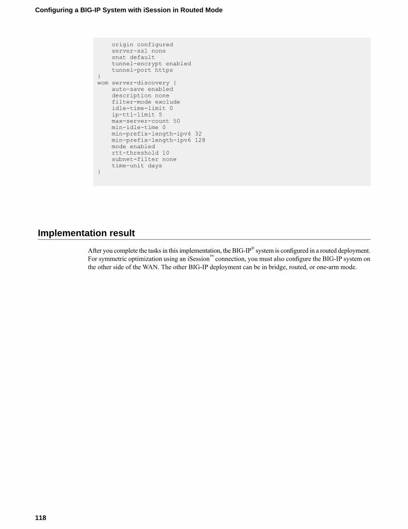
origin configuredserver-ssl nonesnat defaulttunnel-encrypt enabledtunnel-port https
}wom server-discovery {
auto-save enableddescription nonefilter-mode excludeidle-time-limit 0ip-ttl-limit 5max-server-count 50min-idle-time 0min-prefix-length-ipv4 32min-prefix-length-ipv6 128mode enabledrtt-threshold 10subnet-filter nonetime-unit days
}
Implementation result
After you complete the tasks in this implementation, the BIG-IP® system is configured in a routed deployment.For symmetric optimization using an iSession™ connection, you must also configure the BIG-IP system onthe other side of the WAN. The other BIG-IP deployment can be in bridge, routed, or one-arm mode.
118
Configuring a BIG-IP System with iSession in Routed Mode
Chapter
10Setting Up iSession and IPsec To Use NAT Traversal onBoth Sides of the WAN
• Overview: Setting up iSession and IPsec touse NAT traversal on both sides
• Before you begin IPsec configuration• Task summary
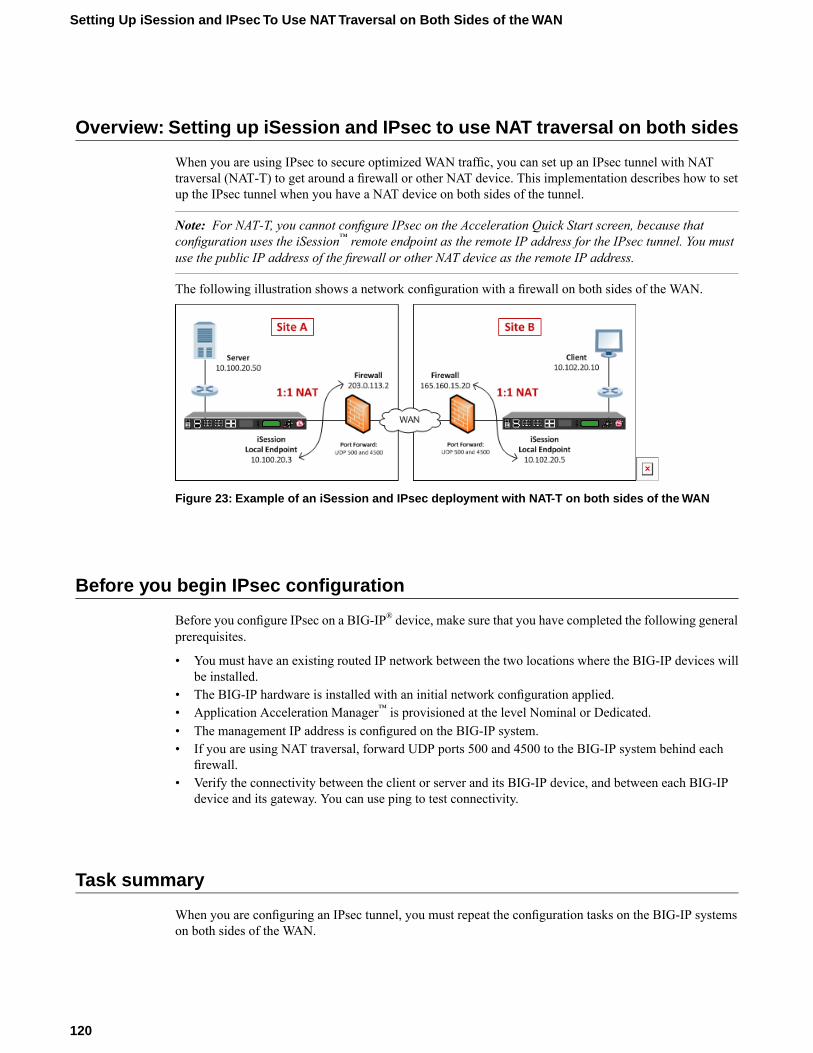
Overview: Setting up iSession and IPsec to use NAT traversal on both sides
When you are using IPsec to secure optimized WAN traffic, you can set up an IPsec tunnel with NATtraversal (NAT-T) to get around a firewall or other NAT device. This implementation describes how to setup the IPsec tunnel when you have a NAT device on both sides of the tunnel.
Note: For NAT-T, you cannot configure IPsec on the Acceleration Quick Start screen, because thatconfiguration uses the iSession™ remote endpoint as the remote IP address for the IPsec tunnel. You mustuse the public IP address of the firewall or other NAT device as the remote IP address.
The following illustration shows a network configuration with a firewall on both sides of the WAN.
Figure 23: Example of an iSession and IPsec deployment with NAT-T on both sides of the WAN
Before you begin IPsec configuration
Before you configure IPsec on a BIG-IP® device, make sure that you have completed the following generalprerequisites.
• You must have an existing routed IP network between the two locations where the BIG-IP devices willbe installed.
• The BIG-IP hardware is installed with an initial network configuration applied.• Application Acceleration Manager™ is provisioned at the level Nominal or Dedicated.• The management IP address is configured on the BIG-IP system.• If you are using NAT traversal, forward UDP ports 500 and 4500 to the BIG-IP system behind each
firewall.• Verify the connectivity between the client or server and its BIG-IP device, and between each BIG-IP
device and its gateway. You can use ping to test connectivity.
Task summary
When you are configuring an IPsec tunnel, you must repeat the configuration tasks on the BIG-IP systemson both sides of the WAN.
120
Setting Up iSession and IPsec To Use NAT Traversal on Both Sides of the WAN

Task listCreating a forwarding virtual server for IPsecCreating an IPsec tunnel with NAT-T on both sidesVerifying IPsec connectivity for Tunnel modeUsing Quick Start to set up iSession endpointsCreating a forwarding virtual server for IPsecCreating an IPsec tunnel with NAT-T on one sideVerifying IPsec connectivity for Tunnel modeUsing Quick Start to set up iSession endpoints
Creating a forwarding virtual server for IPsec
For IPsec, you create a forwarding virtual server to intercept IP traffic and direct it over the tunnel.
1. On the Main tab, click Local Traffic > Virtual Servers.The Virtual Server List screen opens.
2. Click the Create button.The New Virtual Server screen opens.
3. In the Name field, type a unique name for the virtual server.4. From the Type list, select Forwarding (IP).5. For the Destination setting:
a) For Type, select Network.b) In the Address field, type the IP address 0.0.0.0.c) In theMask field, type the netmask 0.0.0.0.
6. From the Service Port list, select *All Ports.7. From the Protocol list, select *All Protocols.8. From the VLAN and Tunnel Traffic list, retain the default selection, All VLANs and Tunnels.9. Click Finished.
Creating an IPsec tunnel with NAT-T on both sides
You can create an IPsec tunnel to securely transport application traffic across theWAN. You must configurethe IPsec tunnel on the BIG-IP systems on both sides of the WAN.
When you create an IKE peer for NAT traversal (NAT-T), the key configuration detail is that the RemoteAddress setting is the public IP address of the firewall or other NAT device (not the IP address of the remoteBIG-IP system). Also, you must turn on NAT traversal. You can customize the remaining settings to conformto your network.
Important: For the IKE peer negotiations to be successful, the IKE Phase 1 and IKE Phase 2 settings mustbe the same on the BIG-IP systems at both ends of the IPsec tunnel.
1. Create an IKE peer that specifies the other end of the IPsec tunnel.a) On the Main tab, click Network > IPsec > IKE Peers.b) Click the Create button.c) In the Name field, type a unique name for the IKE peer.
121
BIG-IP® Acceleration: Network Configuration
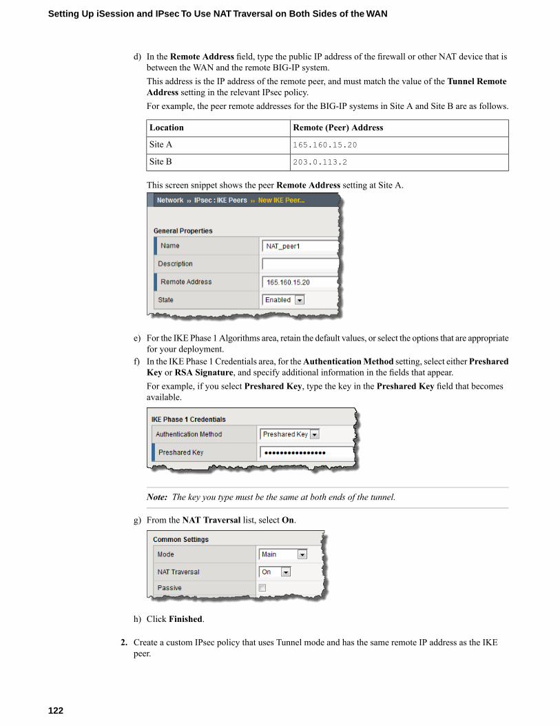
d) In the Remote Address field, type the public IP address of the firewall or other NAT device that isbetween the WAN and the remote BIG-IP system.This address is the IP address of the remote peer, and must match the value of the Tunnel RemoteAddress setting in the relevant IPsec policy.For example, the peer remote addresses for the BIG-IP systems in Site A and Site B are as follows.
Remote (Peer) AddressLocation
165.160.15.20Site A
203.0.113.2Site B
This screen snippet shows the peer Remote Address setting at Site A.
e) For the IKE Phase 1 Algorithms area, retain the default values, or select the options that are appropriatefor your deployment.
f) In the IKE Phase 1 Credentials area, for theAuthenticationMethod setting, select eitherPresharedKey or RSA Signature, and specify additional information in the fields that appear.For example, if you select Preshared Key, type the key in the Preshared Key field that becomesavailable.
Note: The key you type must be the same at both ends of the tunnel.
g) From the NAT Traversal list, select On.
h) Click Finished.
2. Create a custom IPsec policy that uses Tunnel mode and has the same remote IP address as the IKEpeer.
122
Setting Up iSession and IPsec To Use NAT Traversal on Both Sides of the WAN
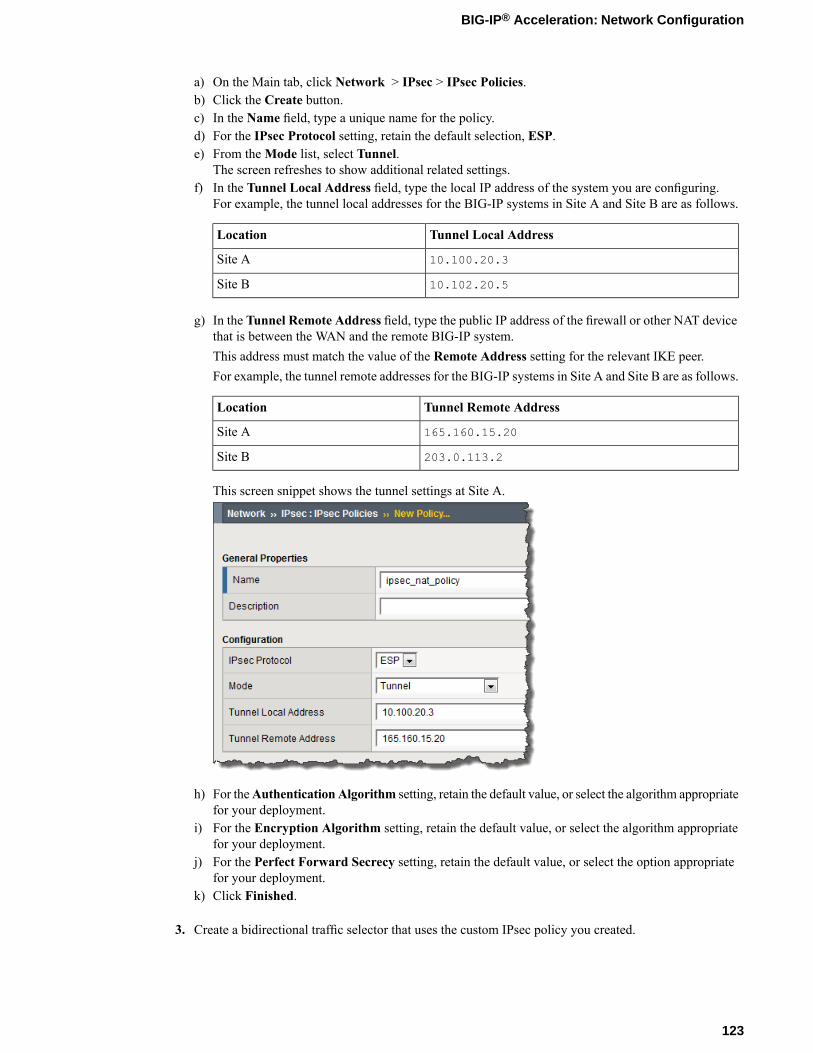
a) On the Main tab, click Network > IPsec > IPsec Policies.b) Click the Create button.c) In the Name field, type a unique name for the policy.d) For the IPsec Protocol setting, retain the default selection, ESP.e) From theMode list, select Tunnel.
The screen refreshes to show additional related settings.f) In the Tunnel Local Address field, type the local IP address of the system you are configuring.
For example, the tunnel local addresses for the BIG-IP systems in Site A and Site B are as follows.
Tunnel Local AddressLocation
10.100.20.3Site A
10.102.20.5Site B
g) In the Tunnel Remote Address field, type the public IP address of the firewall or other NAT devicethat is between the WAN and the remote BIG-IP system.This address must match the value of the Remote Address setting for the relevant IKE peer.For example, the tunnel remote addresses for the BIG-IP systems in Site A and Site B are as follows.
Tunnel Remote AddressLocation
165.160.15.20Site A
203.0.113.2Site B
This screen snippet shows the tunnel settings at Site A.
h) For theAuthenticationAlgorithm setting, retain the default value, or select the algorithm appropriatefor your deployment.
i) For the Encryption Algorithm setting, retain the default value, or select the algorithm appropriatefor your deployment.
j) For the Perfect Forward Secrecy setting, retain the default value, or select the option appropriatefor your deployment.
k) Click Finished.
3. Create a bidirectional traffic selector that uses the custom IPsec policy you created.
123
BIG-IP® Acceleration: Network Configuration

The traffic selector filters the application traffic based on the source and destination IP addresses youspecify.a) On the Main tab, click Network > IPsec > Traffic Selectors.b) Click Create.c) In the Name field, type a unique name for the traffic selector.d) For the Order setting, retain the default value (First).e) For the Source IP Address setting, in the Address field, type the IP address from which the
application traffic originates.For example, the source IP addresses for the BIG-IP systems in Site A and Site B are as follows.
Source IP AddressLocation
10.100.20.50Site A
10.102.20.10Site B
f) In the Destination IP Address setting Address field, type the final IP address for which theapplication traffic is destined.For example, the source IP addresses for the BIG-IP systems in Site A and Site B are as follows.
Destination IP AddressLocation
10.102.20.10Site A
10.100.20.50Site B
g) For the Action setting, retain the default value, Protect.h) From the IPsec Policy Name list, select the name of the custom IPsec policy that you just created.
This portion of a screen is an example of the completed Traffic Selector screen at Site A.
i) Click Finished.
You have now created an IPsec tunnel through which traffic travels in both directions across the WANthrough firewalls on both sides.
124
Setting Up iSession and IPsec To Use NAT Traversal on Both Sides of the WAN

Verifying IPsec connectivity for Tunnel mode
After you have configured an IPsec tunnel and before you configure additional functionality, you can verifythat the tunnel is passing traffic.
Note: Only data traffic matching the traffic selector triggers the establishment of the tunnel.
.
1. Access the tmsh command-line utility.2. Before sending traffic, type this command at the prompt.
tmsh modify net ipsec ike-daemon ikedaemon log-level info
This command increases the logging level to display the INFO messages that you want to view.3. Send data traffic to the destination IP address specified in the traffic selector.4. Check the IKE Phase 1 negotiation status by typing this command at the prompt.
racoonctl -l show-sa isakmp
This example shows a result of the command. Destination is the tunnel remote IP address.
Destination Cookies ST S V E Created Phase2165.160.15.20.500 98993e6 . . . 22c87f1 9 I 10 M 2012-06-27 16:51:19 1
This table shows the legend for interpreting the result.
DescriptionDisplayedColumn
Start Phase 1 negotiation1ST (Tunnel Status)
msg 1 received2
msg 1 sent3
msg 2 received4
msg 2 sent5
msg 3 received6
msg 3 sent7
msg 4 received8
isakmp tunnel established9
isakmp tunnel expired10
InitiatorIS
ResponderR
ISAKMP version 1.010V (Version Number)
Main (Identity Protection)ME (Exchange Mode)
AggressiveA
Number of Phase 2 tunnels negotiated with thisIKE peer
<n>Phase2
125
BIG-IP® Acceleration: Network Configuration

5. Check the IKE Phase 2 negotiation status by typing this command at the prompt.racoonctl -ll show-sa internal
This example shows a result of this command. Source is the tunnel local IP address. Destination isthe tunnel remote IP address.
Source Destination Status Side10.100.20.3 165.160.15.20 sa established [R]
This table shows the legend for interpreting the result.
DisplayedColumn
I (Initiator)Side
R (Responder)
initStatus
start
acquire
getspi sent
getspi done
1st msg sent
1st msg recvd
commit bit
sa added
sa established
sa expired
6. To verify the establishment of dynamic negotiated Security Associations (SAs), type this command atthe prompt.tmsh show net ipsec ipsec-sa
For each tunnel, the output displays IP addresses for two IPsec SAs, one for each direction, as shownin the example.
IPsec::SecurityAssociations10.100.20.3 -> 165.160.15.20 SPI(0x7b438626) in esp (tmm: 6)165.160.15.20 -> 10.100.20.3 SPI(0x5e52a1db) out esp (tmm: 5)
7. To display the details of the dynamic negotiated Security Associations (SAs), type this command at theprompt.tmsh show net ipsec ipsec-sa all-properties
126
Setting Up iSession and IPsec To Use NAT Traversal on Both Sides of the WAN
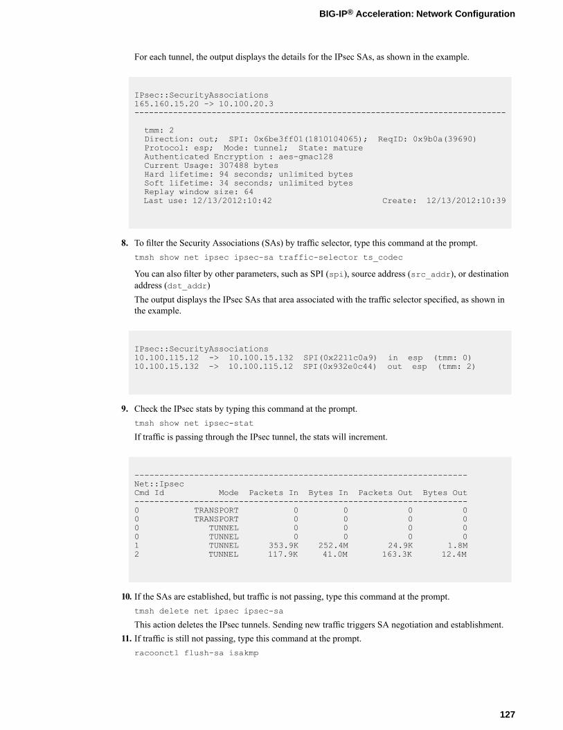
For each tunnel, the output displays the details for the IPsec SAs, as shown in the example.
IPsec::SecurityAssociations165.160.15.20 -> 10.100.20.3-----------------------------------------------------------------------------
tmm: 2Direction: out; SPI: 0x6be3ff01(1810104065); ReqID: 0x9b0a(39690)Protocol: esp; Mode: tunnel; State: matureAuthenticated Encryption : aes-gmac128Current Usage: 307488 bytesHard lifetime: 94 seconds; unlimited bytesSoft lifetime: 34 seconds; unlimited bytesReplay window size: 64Last use: 12/13/2012:10:42 Create: 12/13/2012:10:39
8. To filter the Security Associations (SAs) by traffic selector, type this command at the prompt.tmsh show net ipsec ipsec-sa traffic-selector ts_codec
You can also filter by other parameters, such as SPI (spi), source address (src_addr), or destinationaddress (dst_addr)The output displays the IPsec SAs that area associated with the traffic selector specified, as shown inthe example.
IPsec::SecurityAssociations10.100.115.12 -> 10.100.15.132 SPI(0x2211c0a9) in esp (tmm: 0)10.100.15.132 -> 10.100.115.12 SPI(0x932e0c44) out esp (tmm: 2)
9. Check the IPsec stats by typing this command at the prompt.tmsh show net ipsec-stat
If traffic is passing through the IPsec tunnel, the stats will increment.
-------------------------------------------------------------------Net::IpsecCmd Id Mode Packets In Bytes In Packets Out Bytes Out-------------------------------------------------------------------0 TRANSPORT 0 0 0 00 TRANSPORT 0 0 0 00 TUNNEL 0 0 0 00 TUNNEL 0 0 0 01 TUNNEL 353.9K 252.4M 24.9K 1.8M2 TUNNEL 117.9K 41.0M 163.3K 12.4M
10. If the SAs are established, but traffic is not passing, type this command at the prompt.tmsh delete net ipsec ipsec-sa
This action deletes the IPsec tunnels. Sending new traffic triggers SA negotiation and establishment.11. If traffic is still not passing, type this command at the prompt.
racoonctl flush-sa isakmp
127
BIG-IP® Acceleration: Network Configuration
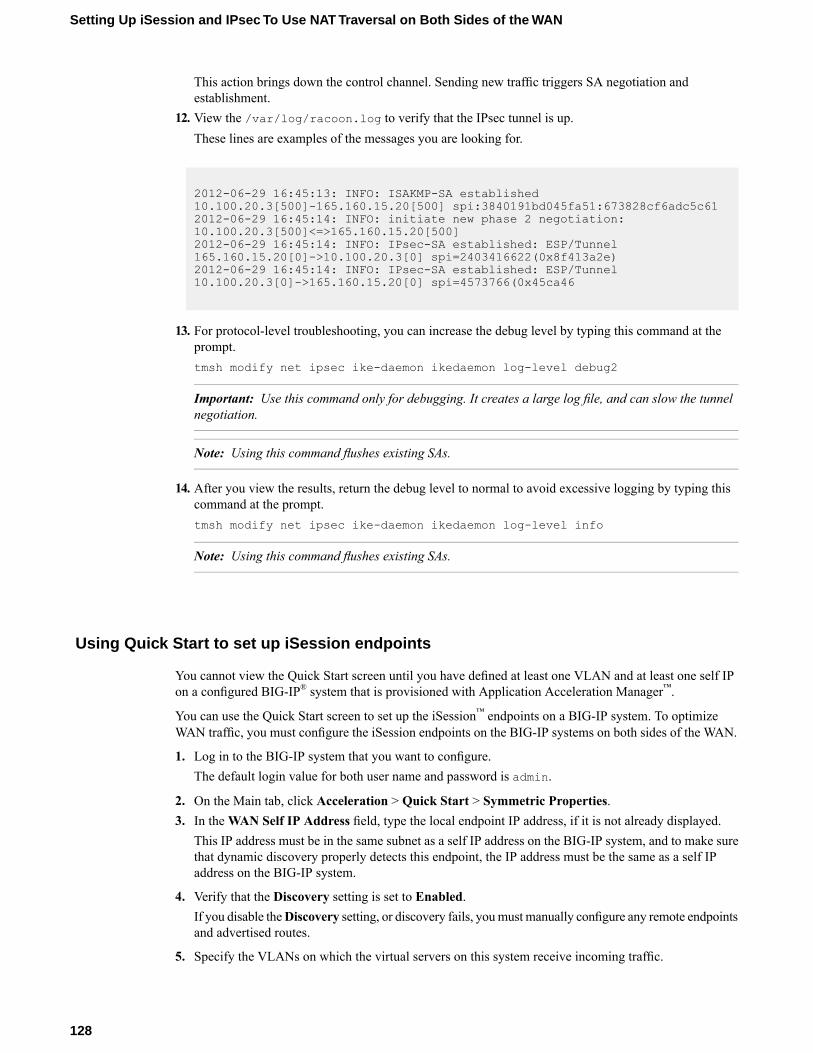
This action brings down the control channel. Sending new traffic triggers SA negotiation andestablishment.
12. View the /var/log/racoon.log to verify that the IPsec tunnel is up.These lines are examples of the messages you are looking for.
2012-06-29 16:45:13: INFO: ISAKMP-SA established10.100.20.3[500]-165.160.15.20[500] spi:3840191bd045fa51:673828cf6adc5c612012-06-29 16:45:14: INFO: initiate new phase 2 negotiation:10.100.20.3[500]<=>165.160.15.20[500]2012-06-29 16:45:14: INFO: IPsec-SA established: ESP/Tunnel165.160.15.20[0]->10.100.20.3[0] spi=2403416622(0x8f413a2e)2012-06-29 16:45:14: INFO: IPsec-SA established: ESP/Tunnel10.100.20.3[0]->165.160.15.20[0] spi=4573766(0x45ca46
13. For protocol-level troubleshooting, you can increase the debug level by typing this command at theprompt.tmsh modify net ipsec ike-daemon ikedaemon log-level debug2
Important: Use this command only for debugging. It creates a large log file, and can slow the tunnelnegotiation.
Note: Using this command flushes existing SAs.
14. After you view the results, return the debug level to normal to avoid excessive logging by typing thiscommand at the prompt.tmsh modify net ipsec ike-daemon ikedaemon log-level info
Note: Using this command flushes existing SAs.
Using Quick Start to set up iSession endpoints
You cannot view the Quick Start screen until you have defined at least one VLAN and at least one self IPon a configured BIG-IP® system that is provisioned with Application Acceleration Manager™.
You can use the Quick Start screen to set up the iSession™ endpoints on a BIG-IP system. To optimizeWAN traffic, you must configure the iSession endpoints on the BIG-IP systems on both sides of the WAN.
1. Log in to the BIG-IP system that you want to configure.The default login value for both user name and password is admin.
2. On the Main tab, click Acceleration > Quick Start > Symmetric Properties.3. In theWAN Self IP Address field, type the local endpoint IP address, if it is not already displayed.
This IP address must be in the same subnet as a self IP address on the BIG-IP system, and to make surethat dynamic discovery properly detects this endpoint, the IP address must be the same as a self IPaddress on the BIG-IP system.
4. Verify that the Discovery setting is set to Enabled.If you disable theDiscovery setting, or discovery fails, youmust manually configure any remote endpointsand advertised routes.
5. Specify the VLANs on which the virtual servers on this system receive incoming traffic.
128
Setting Up iSession and IPsec To Use NAT Traversal on Both Sides of the WAN
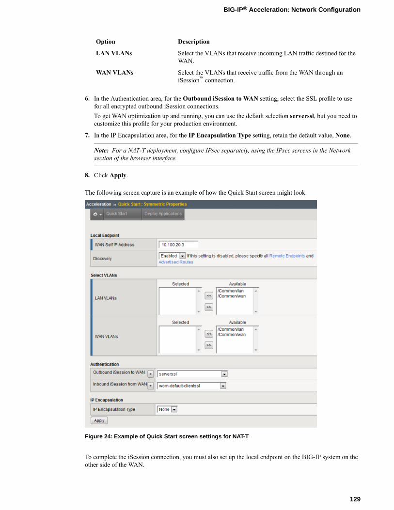
DescriptionOption
Select the VLANs that receive incoming LAN traffic destined for theWAN.
LAN VLANs
Select the VLANs that receive traffic from the WAN through aniSession™ connection.
WAN VLANs
6. In the Authentication area, for the Outbound iSession to WAN setting, select the SSL profile to usefor all encrypted outbound iSession connections.To get WAN optimization up and running, you can use the default selection serverssl, but you need tocustomize this profile for your production environment.
7. In the IP Encapsulation area, for the IP Encapsulation Type setting, retain the default value, None.
Note: For a NAT-T deployment, configure IPsec separately, using the IPsec screens in the Networksection of the browser interface.
8. Click Apply.
The following screen capture is an example of how the Quick Start screen might look.
Figure 24: Example of Quick Start screen settings for NAT-T
To complete the iSession connection, you must also set up the local endpoint on the BIG-IP system on theother side of the WAN.
129
BIG-IP® Acceleration: Network Configuration

Chapter
11Setting Up iSession and IPsec To Use NAT Traversal onOne Side of the WAN
• Overview: Setting up iSession and IPsec touse NAT traversal on one side
• Before you begin IPsec configuration• Task summary
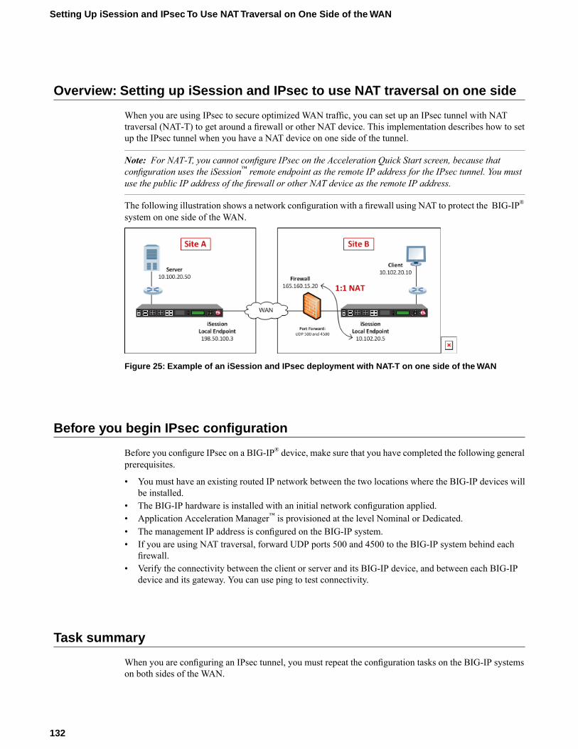
Overview: Setting up iSession and IPsec to use NAT traversal on one side
When you are using IPsec to secure optimized WAN traffic, you can set up an IPsec tunnel with NATtraversal (NAT-T) to get around a firewall or other NAT device. This implementation describes how to setup the IPsec tunnel when you have a NAT device on one side of the tunnel.
Note: For NAT-T, you cannot configure IPsec on the Acceleration Quick Start screen, because thatconfiguration uses the iSession™ remote endpoint as the remote IP address for the IPsec tunnel. You mustuse the public IP address of the firewall or other NAT device as the remote IP address.
The following illustration shows a network configuration with a firewall using NAT to protect the BIG-IP®
system on one side of the WAN.
Figure 25: Example of an iSession and IPsec deployment with NAT-T on one side of the WAN
Before you begin IPsec configuration
Before you configure IPsec on a BIG-IP® device, make sure that you have completed the following generalprerequisites.
• You must have an existing routed IP network between the two locations where the BIG-IP devices willbe installed.
• The BIG-IP hardware is installed with an initial network configuration applied.• Application Acceleration Manager™ is provisioned at the level Nominal or Dedicated.• The management IP address is configured on the BIG-IP system.• If you are using NAT traversal, forward UDP ports 500 and 4500 to the BIG-IP system behind each
firewall.• Verify the connectivity between the client or server and its BIG-IP device, and between each BIG-IP
device and its gateway. You can use ping to test connectivity.
Task summary
When you are configuring an IPsec tunnel, you must repeat the configuration tasks on the BIG-IP systemson both sides of the WAN.
132
Setting Up iSession and IPsec To Use NAT Traversal on One Side of the WAN
Task listCreating a forwarding virtual server for IPsecCreating an IPsec tunnel with NAT-T on both sidesVerifying IPsec connectivity for Tunnel modeUsing Quick Start to set up iSession endpointsCreating a forwarding virtual server for IPsecCreating an IPsec tunnel with NAT-T on one sideVerifying IPsec connectivity for Tunnel modeUsing Quick Start to set up iSession endpoints
Creating a forwarding virtual server for IPsec
For IPsec, you create a forwarding virtual server to intercept IP traffic and direct it over the tunnel.
1. On the Main tab, click Local Traffic > Virtual Servers.The Virtual Server List screen opens.
2. Click the Create button.The New Virtual Server screen opens.
3. In the Name field, type a unique name for the virtual server.4. From the Type list, select Forwarding (IP).5. For the Destination setting:
a) For Type, select Network.b) In the Address field, type the IP address 0.0.0.0.c) In theMask field, type the netmask 0.0.0.0.
6. From the Service Port list, select *All Ports.7. From the Protocol list, select *All Protocols.8. From the VLAN and Tunnel Traffic list, retain the default selection, All VLANs and Tunnels.9. Click Finished.
Creating an IPsec tunnel with NAT-T on one side
You can create an IPsec tunnel to securely transport application traffic across theWAN. You must configurean IPsec tunnel on the BIG-IP systems on both sides of the WAN.
When you create an IKE peer for NAT traversal (NAT-T), the key configuration detail is that the RemoteAddress setting is the public IP address of the firewall or other NAT device (not the IP address of the remoteBIG-IP system). Also, you must turn on NAT traversal for that peer. You can customize the remainingsettings to conform to your network.
Important: For the IKE peer negotiations to be successful, the IKE Phase 1 and IKE Phase 2 settings mustbe the same on the BIG-IP systems at both ends of the IPsec tunnel.
1. Create an IKE peer that specifies the other end of the IPsec tunnel.a) On the Main tab, click Network > IPsec > IKE Peers.b) Click the Create button.c) In the Name field, type a unique name for the IKE peer.
133
BIG-IP® Acceleration: Network Configuration
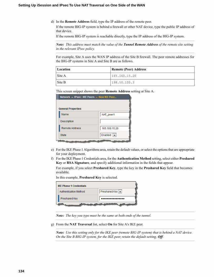
d) In the Remote Address field, type the IP address of the remote peer.If the remote BIG-IP system is behind a firewall or other NAT device, type the public IP address ofthat device.If the remote BIG-IP system is reachable directly, type the IP address of the BIG-IP system.
Note: This address must match the value of the Tunnel Remote Address of the remote site settingin the relevant IPsec policy.
For example, Site A uses the WAN IP address of the Site B firewall. The peer remote addresses forthe BIG-IP systems in Site A and Site B are as follows.
Remote (Peer) AddressLocation
165.160.15.20Site A
198.50.100.3Site B
This screen snippet shows the peer Remote Address setting at Site A.
e) For the IKE Phase 1 Algorithms area, retain the default values, or select the options that are appropriatefor your deployment.
f) For the IKE Phase 1 Credentials area, for theAuthenticationMethod setting, select eitherPresharedKey or RSA Signature, and specify additional information in the fields that appear.For example, if you select Preshared Key, type the key in the Preshared Key field that becomesavailable.In this example, Preshared Key is selected.
Note: The key you type must be the same at both ends of the tunnel.
g) From the NAT Traversal list, select On for Site A's IKE peer.
Note: Use this setting only for the IKE peer (remote BIG-IP system) that is behind a NAT device.On the Site B BIG-IP system, for the IKE peer, retain the default setting, Off.
134
Setting Up iSession and IPsec To Use NAT Traversal on One Side of the WAN
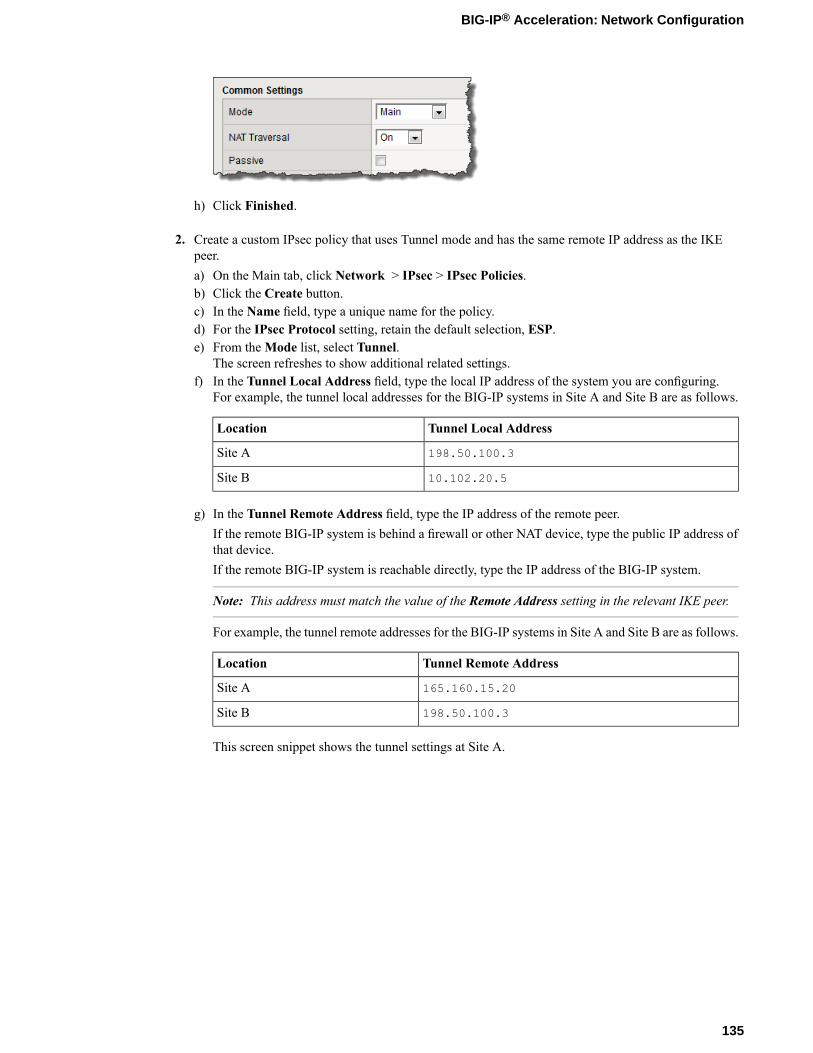
h) Click Finished.
2. Create a custom IPsec policy that uses Tunnel mode and has the same remote IP address as the IKEpeer.a) On the Main tab, click Network > IPsec > IPsec Policies.b) Click the Create button.c) In the Name field, type a unique name for the policy.d) For the IPsec Protocol setting, retain the default selection, ESP.e) From theMode list, select Tunnel.
The screen refreshes to show additional related settings.f) In the Tunnel Local Address field, type the local IP address of the system you are configuring.
For example, the tunnel local addresses for the BIG-IP systems in Site A and Site B are as follows.
Tunnel Local AddressLocation
198.50.100.3Site A
10.102.20.5Site B
g) In the Tunnel Remote Address field, type the IP address of the remote peer.If the remote BIG-IP system is behind a firewall or other NAT device, type the public IP address ofthat device.If the remote BIG-IP system is reachable directly, type the IP address of the BIG-IP system.
Note: This address must match the value of the Remote Address setting in the relevant IKE peer.
For example, the tunnel remote addresses for the BIG-IP systems in Site A and Site B are as follows.
Tunnel Remote AddressLocation
165.160.15.20Site A
198.50.100.3Site B
This screen snippet shows the tunnel settings at Site A.
135
BIG-IP® Acceleration: Network Configuration
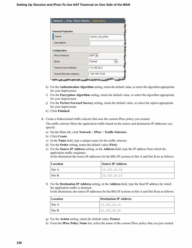
h) For theAuthenticationAlgorithm setting, retain the default value, or select the algorithm appropriatefor your deployment.
i) For the Encryption Algorithm setting, retain the default value, or select the algorithm appropriatefor your deployment.
j) For the Perfect Forward Secrecy setting, retain the default value, or select the option appropriatefor your deployment.
k) Click Finished.
3. Create a bidirectional traffic selector that uses the custom IPsec policy you created.The traffic selector filters the application traffic based on the source and destination IP addresses youspecify.a) On the Main tab, click Network > IPsec > Traffic Selectors.b) Click Create.c) In the Name field, type a unique name for the traffic selector.d) For the Order setting, retain the default value (First).e) For the Source IP Address setting, in the Address field, type the IP address from which the
application traffic originates.In the illustration the source IP addresses for the BIG-IP systems in Site A and Site B are as follows.
Source IP AddressLocation
10.100.20.50Site A
10.102.20.10Site B
f) For the Destination IP Address setting, in the Address field, type the final IP address for whichthe application traffic is destined.In the illustration, the source IP addresses for the BIG-IP systems in Site A and Site B are as follows.
Destination IP AddressLocation
10.102.20.10Site A
10.100.20.50Site B
g) For the Action setting, retain the default value, Protect.h) From the IPsec Policy Name list, select the name of the custom IPsec policy that you just created.
136
Setting Up iSession and IPsec To Use NAT Traversal on One Side of the WAN
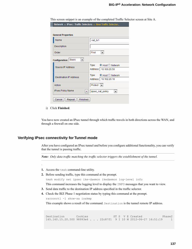
This screen snippet is an example of the completed Traffic Selector screen at Site A.
i) Click Finished.
You have now created an IPsec tunnel through which traffic travels in both directions across the WAN, andthrough a firewall on one side.
Verifying IPsec connectivity for Tunnel mode
After you have configured an IPsec tunnel and before you configure additional functionality, you can verifythat the tunnel is passing traffic.
Note: Only data traffic matching the traffic selector triggers the establishment of the tunnel.
.
1. Access the tmsh command-line utility.2. Before sending traffic, type this command at the prompt.
tmsh modify net ipsec ike-daemon ikedaemon log-level info
This command increases the logging level to display the INFO messages that you want to view.3. Send data traffic to the destination IP address specified in the traffic selector.4. Check the IKE Phase 1 negotiation status by typing this command at the prompt.
racoonctl -l show-sa isakmp
This example shows a result of the command. Destination is the tunnel remote IP address.
Destination Cookies ST S V E Created Phase2165.160.15.20.500 98993e6 . . . 22c87f1 9 I 10 M 2012-06-27 16:51:19 1
137
BIG-IP® Acceleration: Network Configuration
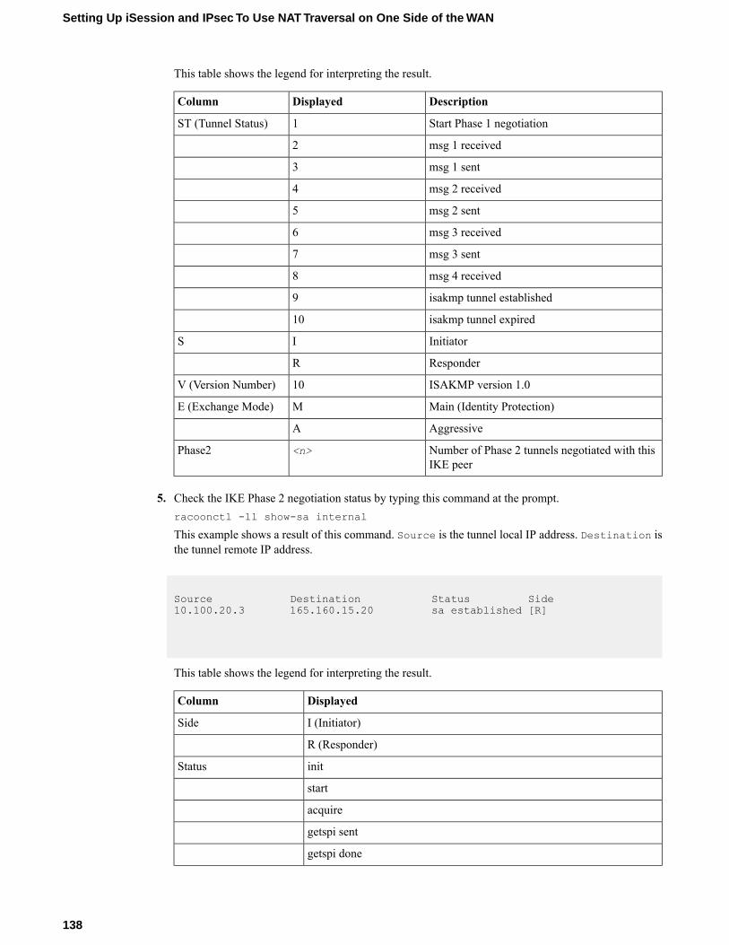
This table shows the legend for interpreting the result.
DescriptionDisplayedColumn
Start Phase 1 negotiation1ST (Tunnel Status)
msg 1 received2
msg 1 sent3
msg 2 received4
msg 2 sent5
msg 3 received6
msg 3 sent7
msg 4 received8
isakmp tunnel established9
isakmp tunnel expired10
InitiatorIS
ResponderR
ISAKMP version 1.010V (Version Number)
Main (Identity Protection)ME (Exchange Mode)
AggressiveA
Number of Phase 2 tunnels negotiated with thisIKE peer
<n>Phase2
5. Check the IKE Phase 2 negotiation status by typing this command at the prompt.racoonctl -ll show-sa internal
This example shows a result of this command. Source is the tunnel local IP address. Destination isthe tunnel remote IP address.
Source Destination Status Side10.100.20.3 165.160.15.20 sa established [R]
This table shows the legend for interpreting the result.
DisplayedColumn
I (Initiator)Side
R (Responder)
initStatus
start
acquire
getspi sent
getspi done
138
Setting Up iSession and IPsec To Use NAT Traversal on One Side of the WAN
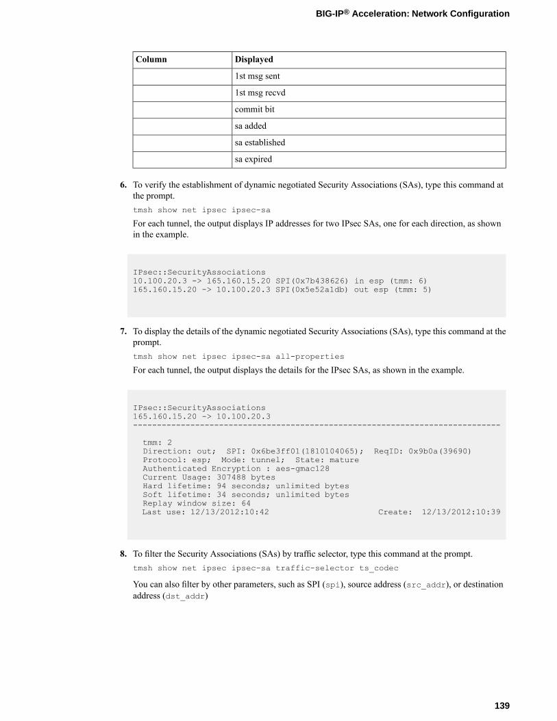
DisplayedColumn
1st msg sent
1st msg recvd
commit bit
sa added
sa established
sa expired
6. To verify the establishment of dynamic negotiated Security Associations (SAs), type this command atthe prompt.tmsh show net ipsec ipsec-sa
For each tunnel, the output displays IP addresses for two IPsec SAs, one for each direction, as shownin the example.
IPsec::SecurityAssociations10.100.20.3 -> 165.160.15.20 SPI(0x7b438626) in esp (tmm: 6)165.160.15.20 -> 10.100.20.3 SPI(0x5e52a1db) out esp (tmm: 5)
7. To display the details of the dynamic negotiated Security Associations (SAs), type this command at theprompt.tmsh show net ipsec ipsec-sa all-properties
For each tunnel, the output displays the details for the IPsec SAs, as shown in the example.
IPsec::SecurityAssociations165.160.15.20 -> 10.100.20.3-----------------------------------------------------------------------------
tmm: 2Direction: out; SPI: 0x6be3ff01(1810104065); ReqID: 0x9b0a(39690)Protocol: esp; Mode: tunnel; State: matureAuthenticated Encryption : aes-gmac128Current Usage: 307488 bytesHard lifetime: 94 seconds; unlimited bytesSoft lifetime: 34 seconds; unlimited bytesReplay window size: 64Last use: 12/13/2012:10:42 Create: 12/13/2012:10:39
8. To filter the Security Associations (SAs) by traffic selector, type this command at the prompt.tmsh show net ipsec ipsec-sa traffic-selector ts_codec
You can also filter by other parameters, such as SPI (spi), source address (src_addr), or destinationaddress (dst_addr)
139
BIG-IP® Acceleration: Network Configuration
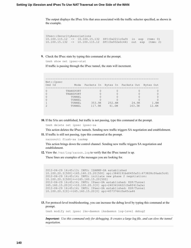
The output displays the IPsec SAs that area associated with the traffic selector specified, as shown inthe example.
IPsec::SecurityAssociations10.100.115.12 -> 10.100.15.132 SPI(0x2211c0a9) in esp (tmm: 0)10.100.15.132 -> 10.100.115.12 SPI(0x932e0c44) out esp (tmm: 2)
9. Check the IPsec stats by typing this command at the prompt.tmsh show net ipsec-stat
If traffic is passing through the IPsec tunnel, the stats will increment.
-------------------------------------------------------------------Net::IpsecCmd Id Mode Packets In Bytes In Packets Out Bytes Out-------------------------------------------------------------------0 TRANSPORT 0 0 0 00 TRANSPORT 0 0 0 00 TUNNEL 0 0 0 00 TUNNEL 0 0 0 01 TUNNEL 353.9K 252.4M 24.9K 1.8M2 TUNNEL 117.9K 41.0M 163.3K 12.4M
10. If the SAs are established, but traffic is not passing, type this command at the prompt.tmsh delete net ipsec ipsec-sa
This action deletes the IPsec tunnels. Sending new traffic triggers SA negotiation and establishment.11. If traffic is still not passing, type this command at the prompt.
racoonctl flush-sa isakmp
This action brings down the control channel. Sending new traffic triggers SA negotiation andestablishment.
12. View the /var/log/racoon.log to verify that the IPsec tunnel is up.These lines are examples of the messages you are looking for.
2012-06-29 16:45:13: INFO: ISAKMP-SA established10.100.20.3[500]-165.160.15.20[500] spi:3840191bd045fa51:673828cf6adc5c612012-06-29 16:45:14: INFO: initiate new phase 2 negotiation:10.100.20.3[500]<=>165.160.15.20[500]2012-06-29 16:45:14: INFO: IPsec-SA established: ESP/Tunnel165.160.15.20[0]->10.100.20.3[0] spi=2403416622(0x8f413a2e)2012-06-29 16:45:14: INFO: IPsec-SA established: ESP/Tunnel10.100.20.3[0]->165.160.15.20[0] spi=4573766(0x45ca46
13. For protocol-level troubleshooting, you can increase the debug level by typing this command at theprompt.tmsh modify net ipsec ike-daemon ikedaemon log-level debug2
Important: Use this command only for debugging. It creates a large log file, and can slow the tunnelnegotiation.
140
Setting Up iSession and IPsec To Use NAT Traversal on One Side of the WAN

Note: Using this command flushes existing SAs.
14. After you view the results, return the debug level to normal to avoid excessive logging by typing thiscommand at the prompt.tmsh modify net ipsec ike-daemon ikedaemon log-level info
Note: Using this command flushes existing SAs.
Using Quick Start to set up iSession endpoints
You cannot view the Quick Start screen until you have defined at least one VLAN and at least one self IPon a configured BIG-IP® system that is provisioned with Application Acceleration Manager™.
You can use the Quick Start screen to set up the iSession™ endpoints on a BIG-IP system. To optimizeWAN traffic, you must configure the iSession endpoints on the BIG-IP systems on both sides of the WAN.
1. Log in to the BIG-IP system that you want to configure.The default login value for both user name and password is admin.
2. On the Main tab, click Acceleration > Quick Start > Symmetric Properties.3. In theWAN Self IP Address field, type the local endpoint IP address, if it is not already displayed.
This IP address must be in the same subnet as a self IP address on the BIG-IP system, and to make surethat dynamic discovery properly detects this endpoint, the IP address must be the same as a self IPaddress on the BIG-IP system.
4. Verify that the Discovery setting is set to Enabled.If you disable theDiscovery setting, or discovery fails, youmust manually configure any remote endpointsand advertised routes.
5. Specify the VLANs on which the virtual servers on this system receive incoming traffic.DescriptionOption
Select the VLANs that receive incoming LAN traffic destined for theWAN.
LAN VLANs
Select the VLANs that receive traffic from the WAN through aniSession™ connection.
WAN VLANs
6. In the Authentication area, for the Outbound iSession to WAN setting, select the SSL profile to usefor all encrypted outbound iSession connections.To get WAN optimization up and running, you can use the default selection serverssl, but you need tocustomize this profile for your production environment.
7. In the IP Encapsulation area, for the IP Encapsulation Type setting, retain the default value, None.
Note: For a NAT-T deployment, configure IPsec separately, using the IPsec screens in the Networksection of the browser interface.
8. Click Apply.
The following screen capture is an example of how the Quick Start screen might look.
141
BIG-IP® Acceleration: Network Configuration
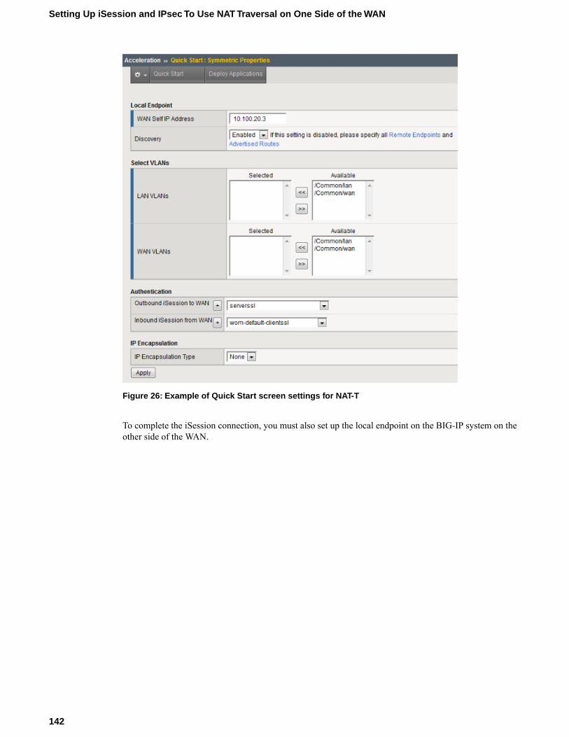
Figure 26: Example of Quick Start screen settings for NAT-T
To complete the iSession connection, you must also set up the local endpoint on the BIG-IP system on theother side of the WAN.
142
Setting Up iSession and IPsec To Use NAT Traversal on One Side of the WAN

Chapter
12Disk Management for Datastor
• About disk management• Task summary
About disk management
You can use disk management to allocate dedicated disk space for the datastor service, which increases thedata storage that BIG-IP® Application Acceleration Manager™ (AAM™) uses for deduplication. Additionaldisk space is available in the following deployments.
• If you are installing BIG-IP AAMVirtual Edition, you can select an extra disk deployment configuration.• Selected higher-end BIG-IP AAM platforms support the use of solid-state drives (SSDs) that come in
a dual-disk drive sled and are installed along with hard disk drives.
Task summary
Perform these tasks to configure disk management for Application Acceleration Manager™ (AAM™).
Task listProvisioning extra VE disk for datastorProvisioning solid-state drives for datastorMonitoring SSD usage
Provisioning extra VE disk for datastor
Before beginning this procedure, you must have licensed and configured BIG-IP®Application AccelerationManager™ (AAM™) Virtual Edition (VE).
If you selected one of the extra disk options when you configured BIG-IP AAM VE, you must manuallyallocate the disk space to the datastor service, after you delete the datastor application volume from theprimary disk. Datastor cannot span the primary disk and the extra disk.
1. On the Main tab, click System > Resource Provisioning.You must de-provision AAM before you can delete the datastor allocation from the primary disk.
2. In the Provisioning column. clear the Application Acceleration Manager (AAM) check box.3. Click Submit.4. Click OK to proceed.
The BIG-IP system restarts without AAM in the configuration, which might take a minute or so.5. Click Continue.6. On the Main tab under System, click Disk Management.7. In the Logical View area, click HD1.
The General Properties screen opens for the primary disk.8. In the Contained Application Volumes area, select the check box for Datastor, and click Delete.9. On the Disk Management screen, click HD2.
The General Properties screen opens for the extra disk.10. In the General Properties area, for theMode setting, select Datastor.11. Click Update.12. On the Main tab under System, click Resource Provisioning.
144
Disk Management for Datastor
13. In the Resource Provisioning (Licensed Modules) area, from the Application Acceleration Manager(AAM) list, select a provisioning setting that applies to your environment.
14. Click Submit.15. Click OK to proceed.
The BIG-IP system restarts with AAM in the configuration, which may take a minute or so.16. Click Continue.
The datastor is now allocated to the extra disk. You can verify the result by checking the Disk Managementscreen.
Provisioning solid-state drives for datastor
Before beginning this procedure, you must have licensed Application Acceleration Manager™ (AAM™).
By default, datastor, which is the data storage used for optimization, is provisioned on the primary harddisk drive (HDD). To use solid-state drives (SSDs) on BIG-IP® AAM, you must manually allocate the diskspace on each SSD to the datastor service. If you install SSDs after you have provisioned AAM, you mustfirst de-provision AAM, and then delete the datastor application volume from the primary disk, before youassign the datastor service to the SSD volume.
1. On the Main tab, click System > Resource Provisioning.2. In the Provisioning column. clear the Application Acceleration Manager (AAM) check box.3. Click Submit.4. Click OK to proceed.
The BIG-IP system restarts without AAM in the configuration, which might take a minute or so.5. Click Continue.6. On the Main tab under System, click Disk Management.7. If the Logical View shows Datastor allocation on HD1, delete it by performing the following steps.
If datastor is not allocated to HD1, skip this step.
Note: Datastor does not span the primary disk and the SSDs. If datastor is allocated to the primarydisk, it will not use the SSDs.
a) Click the disk label, for example HD1.The General Properties screen opens for the logical disk you selected.
b) In the Contained Application Volumes area, select the check box for Datastor, and click Delete.
8. On the Disk Management screen, click the SSD disk label, for example, SSD1.The General Properties screen opens for the logical disk you selected.
9. For theMode setting, select Datastor.10. Click Update.11. Repeat the datastor selection steps for each SSD displayed on the Disk Management screen.12. On the Main tab under System, click Resource Provisioning.13. In the Resource Provisioning (Licensed Modules) area, from the Application Acceleration Manager
(AAM) list, select Nominal.14. Click Submit.15. Click OK to proceed.
The BIG-IP system restarts with AAM in the configuration, which might take a minute or so.16. Click Continue.
145
BIG-IP® Acceleration: Network Configuration
The datastor service is now allocated to the SSDs. The datastor volume spans the installed SSDs. You canverify the result by checking the DiskManagement screen. The logical view displays the datastor allocationfor each disk.
Monitoring SSD usage
If you are using solid-state drives (SSDs) for datastor, you can view the SSD allocation and monitor theSSD lifespan.
1. On the Main tab under System, click Disk Management.2. Use the Disk Management screen to view details about the SSDs, including the following.
• To view the general properties of a disk, in the Logical View area, click the disk label.• In the Physical View area, note which bays contain the SSDs.• In the Data Disks area, view the Media Wearout Indicator to monitor disk usage.
146
Disk Management for Datastor

Index
A
Acceleration cacheclearing 28, 43
advertised routesadding manually 26
application profilecreating 23, 39, 57creating for a server farm 52
asymmetric HTTP traffic accelerationresults 59task summary 56
authenticationand device identity 18, 34, 48and local trust domains 17, 33, 47
authoritychanging 17, 33, 47
automatic synchronizationenabling and disabling 20, 36, 49
B
BIG-IPasymmetric deployment 56server farm deployment 46
bridge modeconfiguration result 101configuring 88configuring for iSession connection 89configuring for symmetric optimization 89deployment illustration 88viewing configuration details 95
C
certificatesfor device trust 19, 35, 49
Cisco routerconfiguring for one-arm deployment 79
configuration synchronizationsyncing to group 21, 37, 50
connectionscreating pools for 24, 40, 53, 58
connectivitychecking 76verifying 92, 108
D
datastorallocating to SSDs 145
destination IP addressesfor traffic selectors 121, 133
device discoveryfor device trust 19, 35, 49
device groupscreating 20, 36, 49
device identitydefined 18, 34, 48
device trustabout 17, 33, 47adding domain members 19, 35, 49
diagnosticsand error messages 66running for symmetric optimization 67testing iSession connectivity across WAN 67troubleshooting symmetric optimization 66
disk managementallocating datastor to SSDs 145of SSDs 144
E
error messagesand diagnostics 66
F
foldercreating for synchronized acceleration applications 22, 38, 51, 57
forwarding virtual serverscreating for IPsec 121, 133
G
gatewaycreating default 107
global networkdeployment 16, 32
H
headerssymmetric 17, 33
HTTP traffic acceleration in a server farmoverview 46
I
IPsec configurationsprerequisites for 120, 132
IPsec IKE peerscreating for NAT-T 121, 133
IPsec policiescreating for NAT-T 121, 133
IPsec traffic selectorscreating for NAT-T 121, 133
IPsec tunnelcreating for NAT-T 121, 133verifying connectivity 125, 137
IPsec Tunnel mode, See Tunnel modeiSession
and IPsec with NAT-T 120, 132
147
Index

iSession (continued)and symmetric optimization 104prerequisites for configuring 71, 88, 105
iSession configurationvalidating 94, 110validating for one-arm 79
iSession endpointssetting up 25, 28, 128, 141
L
lifespanof SSDs 146
local trust domainand device groups 20, 36, 49defined 17, 19, 33, 35, 47, 49
N
NAT traversalusing IPsec 120, 132
networkconfiguring bridge mode 88configuring one-arm deployment 70configuring routed mode 104
NTP serverdefining 19, 21, 26, 35, 38, 41, 48, 51, 56
O
one-arm deploymentconfiguration result 86configuring Cisco router 79configuring WCCPv2 74overview 70using WCCPv2 72verifying WCCPv2 configuration 77viewing iSession configuration 81
P
passthrough virtual servers108
creating 108Policies
creating user-defined from predefined 22, 38, 52, 57pools
creating for HTTP traffic 24, 40, 53, 58predefined policy
copying 22, 38, 52, 57prerequisites
for configuring IPsec 120, 132for configuring iSession 71, 88, 105
Q
Quick Start screenabout 62and iSession listeners 25, 28and traffic termination 25, 28configuring iSession endpoints 62
Quick Start screen (continued)configuring one-arm deployment 77setting up iSession endpoints 25, 28, 128, 141using to configure iSession 92, 108
R
routed modeconfiguration result 118configuring 104configuring for iSession connection 106configuring for symmetric optimization 106deployment illustration 104viewing configuration details 111
routesdefining 92defining default 74
routingbridge mode 88one-arm mode 70routed mode 104
S
secure channelsestablishing 120, 132
self IP addressesconfiguring for external VLANs 107configuring for internal VLANs 107creating for one-arm deployment 73creating for VLAN groups 91
server farm HTTP traffic accelerationresults 54task summary 51
solid-state drives (SSDs)about 144monitoring usage 146provisioning for AAM 145
symmetric HTTP traffic accelerationoverview 16, 32results 29, 43task summary 21, 26, 37, 41
symmetric optimizationoverview 104
sync-only device grouptask summary 18, 35, 48
Sync-Only device groupscreating 20, 36, 49
T
traffic redirectionabout WCCPv2 70
traffic selectors, See IPsec traffic selectorstroubleshooting
running symmetric optimization diagnostics 67testing iSession connectivity across WAN 67
trust domainsand local trust domain 17, 19, 33, 35, 47, 49
trust relationshipsbetween devices 17, 33, 47
148
Index

Tunnel modeverifying connectivity 125, 137
U
user-defined policycreating from predefined 22, 38, 52, 57
V
Virtual Edition (VE)provisioning extra drive 144
virtual servers 108See also forwarding virtual serversSee also passthrough virtual servers
adding to advertised routes 26creating for HTTP traffic 24, 27, 40, 42, 54, 59creating with Quick Start screen 25, 28See also forwarding virtual serversSee also passthrough virtual servers
VLAN groupscreating for bridge deployment 90
VLANscreating 89, 106creating for one-arm deployment 72
W
WCCPv2checking connectivity 76configuring 74configuring one-arm deployment 70, 72description 70verifying configuration 77
Web Acceleration profileenabling 23, 27, 39, 42, 53, 58
X
x509 certificatesand device identity 18, 34, 48and device trust 17, 33, 47
149
Index

150
Index