Bicycle-Specific Traffic Signals - Computer Action...
9
1 Transportation Research Record: Journal of the Transportation Research Board, No. 2387, Transportation Research Board of the National Academies, Washington, D.C., 2013, pp. 1–9. DOI: 10.3141/2387-01 S. R. Thompson, C. M. Monsere, and M. Figliozzi, Department of Civil and Envi- ronmental Engineering, Portland State University, P.O. Box 751, Portland, OR 97201. P. Koonce, Bureau of Transportation, City of Portland, 1120 Southwest Fifth Avenue, Room 800, Portland, OR 97204. G. Obery, Oregon Department of Transportation, 4040 Fairview Industrial Drive, MS#5, Salem, OR 97302-1142. Corresponding author: C. M. Monsere, [email protected]. less-confident riders, because they increase the overall stress level of an otherwise low-stress route (8). Insecurities about safety and gaps in connectivity at intersections pose barriers to cycling that can be alleviated through the selected application of bicycle signals. Bicycle-specific traffic signals are heads used at intersections with conventional signals to specifically control cyclist movements. Typi- cally, these signals are not viewable by motorists, or they are distin- guished from other signal heads through special signage, bicycle indications, or signal housing color. They are common elements in the networks of Europe, where cycling is popular (9). Under the con- trol of a bicycle-specific traffic signal, cyclist movements may occur concurrently with other compatible vehicle phases or exclusively on a separate phase. In Europe, bicycle signals are most commonly used to implement leading intervals, to signalize bike-only approaches, and to separate turning motorists and through cyclists. Presently, bicycle- specific signals are limited by the Manual on Uniform Traffic Control Devices (MUTCD) to the display of 8- or 12-in. circular or arrow indications (10). The State of California has specified that bicycle- specific traffic signals shall display red, yellow, and green symbols (11). Thus the use of bicycle-specific signals in the United States has been limited to a small number of jurisdictions. Such signals are addressed in the MUTCD for Canada (12). The purpose of the study presented in this paper was to present the existing state of the practice that relates to bicycle-specific signals. The primary focus of the synthesis was the United States (although information was included from installations and guidance from Canada). The remainder of this paper is organized as follows: First, a short synthesis is presented of the engineering guidance documents that address bicycle-specific signals. Definitions in vehicle codes are included. Little published literature relates to bicycle-specific signals, and what does exist is presented elsewhere (13, 14). Second, the results are presented of a survey of jurisdictions with known installations of bicycle-specific signals. Surveys were sent to agencies in 21 jurisdic- tions (19 in the United States and two in Canada), which requested details on the engineering aspects of their bicycle signals (e.g., place- ment, mounting height, lens diameter, backplate color, type of actua- tion, interval times, use of louvers, performance). Responses were received on 63 intersections and 149 signal heads. The paper concludes with a summary and some discussion of research needs. ENGINEERING GUIDANCE DOCUMENTS The following documents were reviewed with respect to their engi- neering guidance: • Urban Bikeway Design Guide (15), • Guide for the Development of Bicycle Facilities (16), Bicycle-Specific Traffic Signals Results from a State-of-the-Practice Review Sam R. Thompson, Christopher M. Monsere, Miguel Figliozzi, Peter Koonce, and Gary Obery This paper presents the results of a survey of North American juris- dictions with known installations of bicycle-specific traffic signals and a review of available engineering guidance. Surveys were sent to agen- cies in 21 jurisdictions (19 in the United States and two in Canada). The surveys requested details on the engineering aspects of the jurisdictions’ signal designs (e.g., placement, mounting height, lens diameter, backplate color, type of actuation, interval times, use of louvers, performance). Sur- vey responses were received for 63 intersections and 149 separate signal heads, and the results highlighted current treatments and variations in similar designs. The guidance documents that were reviewed included those produced by the National Association of City Transportation Offi- cials, New York; AASHTO, Washington, D.C.; the Transportation Asso- ciation of Canada, Ottawa, Ontario; CROW, Ede, Netherlands; and the respective manuals on uniform traffic control devices of Canada, the United States, and the State of California. A subsequent review of the doc- uments revealed consistent guidance in general with regard to the design of bicycle-specific traffic signals. Guidance on bicycle signals has grown substantially in recent years, so future designs are likely to vary less. An increase in cycling as a regular mode of transportation has many personal and environmental benefits, which have been noted in recent literature (1). These benefits, paired with growing concerns about pollution and traffic congestion from personal car use, have motivated many municipalities to provide more choices in infra- structure and bicycle-specific facilities, especially for new or less- confident riders (1, 2). Although cyclists are willing to travel out of their way to use bicycle infrastructure, minimized trip distance and improved connectivity are important factors in their route choices (2). Cohesion between network components and direct routes is an essential element of a bicycle network, as documented in the CROW Design Manual for Bicycle Traffic (3). Difficult connections or crossing opportunities create disconti- nuities in a bicycle network, and they decrease perceived cyclist safety and comfort (4). Safety, or its perception, has been cited as a significant factor in people’s decision to cycle (5–7 ). Difficult con- nections obstruct direct routes or decrease their attractiveness to
Transcript of Bicycle-Specific Traffic Signals - Computer Action...
1
Transportation Research Record: Journal of the Transportation Research Board, No. 2387, Transportation Research Board of the National Academies, Washington, D.C., 2013, pp. 1–9.DOI: 10.3141/2387-01
S. R. Thompson, C. M. Monsere, and M. Figliozzi, Department of Civil and Envi-ronmental Engineering, Portland State University, P.O. Box 751, Portland, OR 97201. P. Koonce, Bureau of Transportation, City of Portland, 1120 Southwest Fifth Avenue, Room 800, Portland, OR 97204. G. Obery, Oregon Department of Transportation, 4040 Fairview Industrial Drive, MS#5, Salem, OR 97302-1142. Corresponding author: C. M. Monsere, [email protected].
less-confident riders, because they increase the overall stress level of an otherwise low-stress route (8). Insecurities about safety and gaps in connectivity at intersections pose barriers to cycling that can be alleviated through the selected application of bicycle signals.
Bicycle-specific traffic signals are heads used at intersections with conventional signals to specifically control cyclist movements. Typi-cally, these signals are not viewable by motorists, or they are distin-guished from other signal heads through special signage, bicycle indications, or signal housing color. They are common elements in the networks of Europe, where cycling is popular (9). Under the con-trol of a bicycle-specific traffic signal, cyclist movements may occur concurrently with other compatible vehicle phases or exclusively on a separate phase. In Europe, bicycle signals are most commonly used to implement leading intervals, to signalize bike-only approaches, and to separate turning motorists and through cyclists. Presently, bicycle-specific signals are limited by the Manual on Uniform Traffic Control Devices (MUTCD) to the display of 8- or 12-in. circular or arrow indications (10). The State of California has specified that bicycle-specific traffic signals shall display red, yellow, and green symbols (11). Thus the use of bicycle-specific signals in the United States has been limited to a small number of jurisdictions. Such signals are addressed in the MUTCD for Canada (12).
The purpose of the study presented in this paper was to present the existing state of the practice that relates to bicycle-specific signals. The primary focus of the synthesis was the United States (although information was included from installations and guidance from Canada). The remainder of this paper is organized as follows: First, a short synthesis is presented of the engineering guidance documents that address bicycle-specific signals. Definitions in vehicle codes are included. Little published literature relates to bicycle-specific signals, and what does exist is presented elsewhere (13, 14). Second, the results are presented of a survey of jurisdictions with known installations of bicycle-specific signals. Surveys were sent to agencies in 21 jurisdic-tions (19 in the United States and two in Canada), which requested details on the engineering aspects of their bicycle signals (e.g., place-ment, mounting height, lens diameter, backplate color, type of actua-tion, interval times, use of louvers, performance). Responses were received on 63 intersections and 149 signal heads. The paper concludes with a summary and some discussion of research needs.
ENGINEERING GUIDANCE DOCUMENTS
The following documents were reviewed with respect to their engi-neering guidance:
• Urban Bikeway Design Guide (15),• Guide for the Development of Bicycle Facilities (16),
Bicycle-Specific Traffic SignalsResults from a State-of-the-Practice Review
Sam R. Thompson, Christopher M. Monsere, Miguel Figliozzi, Peter Koonce, and Gary Obery
This paper presents the results of a survey of North American juris-dictions with known installations of bicycle-specific traffic signals and a review of available engineering guidance. Surveys were sent to agen-cies in 21 jurisdictions (19 in the United States and two in Canada). The surveys requested details on the engineering aspects of the jurisdictions’ signal designs (e.g., placement, mounting height, lens diameter, backplate color, type of actuation, interval times, use of louvers, performance). Sur-vey responses were received for 63 intersections and 149 separate signal heads, and the results highlighted current treatments and variations in similar designs. The guidance documents that were reviewed included those produced by the National Association of City Transportation Offi-cials, New York; AASHTO, Washington, D.C.; the Transportation Asso-ciation of Canada, Ottawa, Ontario; CROW, Ede, Netherlands; and the respective manuals on uniform traffic control devices of Canada, the United States, and the State of California. A subsequent review of the doc-uments revealed consistent guidance in general with regard to the design of bicycle-specific traffic signals. Guidance on bicycle signals has grown substantially in recent years, so future designs are likely to vary less.
An increase in cycling as a regular mode of transportation has many personal and environmental benefits, which have been noted in recent literature (1). These benefits, paired with growing concerns about pollution and traffic congestion from personal car use, have motivated many municipalities to provide more choices in infra-structure and bicycle-specific facilities, especially for new or less-confident riders (1, 2). Although cyclists are willing to travel out of their way to use bicycle infrastructure, minimized trip distance and improved connectivity are important factors in their route choices (2). Cohesion between network components and direct routes is an essential element of a bicycle network, as documented in the CROW Design Manual for Bicycle Traffic (3).
Difficult connections or crossing opportunities create disconti-nuities in a bicycle network, and they decrease perceived cyclist safety and comfort (4). Safety, or its perception, has been cited as a significant factor in people’s decision to cycle (5–7). Difficult con-nections obstruct direct routes or decrease their attractiveness to

2 Transportation Research Record 2387
• California MUTCD (11),• MUTCD (10),• Traffic Signal Guidelines for Bicycles (17),• MUTCD for Canada (12), and• Design Manual for Bicycle Traffic (3).
The review categories are arranged in the same order as the state-of-the-practice review presented in the next section.
Physical Elements
As suggested by the National Association of City Transportation Offi-cials (NACTO), much of the guidance about regular traffic signals can be considered when bicycle-specific signals are designed (15). In this review, only specific references to bicycle-specific signals or cyclists were identified in the documents.
Signal Head
Lens Size The U.S. MUTCD permits the use of an 8-in. circu-lar indication for the “sole purpose of controlling a bikeway or a bi cycle movement” in Sec. 4D.07, Size of Vehicular Signal Indi-cations (10, p. 457). This wording is consistent with that in Cali-fornia’s MUTCD (11). The Canadian MUTCD states that standard bicycle signal lenses are 200-mm (8-in.) circular lenses (12). When the lens is more than 30 m (98.4 ft) away from stopped cyclists, 300-mm (12-in.) lenses may be considered.
Use of Bicycle Insignia in Lens The U.S. MUTCD prohibits the use of a red-yellow-green bicycle stencil in lenses (10). The Cali-fornia manual, however, requires the use of the bicycle insignia and states that “only green, yellow and red lighted bicycle symbols shall be used to implement bicycle movement at a signalized inter section” (11, p. 896). The bicycle stencil faces left. Transportation Associa-tion of Canada (TAC) guidance from Traffic Signal Guidelines incor-porates the guidance from Quebec, Canada, and the stencil faces left (17). The NACTO design guidance features an illustration of the bicycle signal head with insignia that faces right (15). The direction of the stencil is a detail that most likely does not affect comprehen-sion or operation but does highlight design differences. The U.S. MUTCD does allow sign symbols to be reversed if “the reverse ori-entation might better convey to road users a direction of movement” (10, p. 35). None of the documents provided guidance on indications that could be used to indicate protected movements. The TAC Traffic Signal Guidelines, however, notes that bicycle signals are intended to signal permissive movements only, with all bicycle movements permitted unless signage indicates otherwise (17).
Optional Elements: Color and Backplates The NACTO and TAC guidelines recommend that the color of the signal housing be different than that of the vehicle signal housing, presumably for improved visibility (15, 17). TAC guidance suggests that bicycle signals be black (opposite the yellow housings for motorist signals) to further distinguish their special use (17).
Placement and Mounting
The placement and the mounting height of the bicycle signal head clearly depend on the particular intersection and the movement to be
controlled. The guidance in the reviewed documents is summarized in the following sections.
Visibility for the Cyclist The NACTO design guidance explicitly states that signal heads are to be “placed in a location clearly visible to oncoming bicycles” (15, p. 132) with near-side placement as an “optional” enhancement to visibility. This guide’s illustrations display the bicycle signal mounted over the pedestrian head.
TAC guidance also suggests supplemental near-side displays for wide intersections, or those with complex geometry, and specifies that one signal head should be installed in the field of vision of cyclists or within 30 m (98.4 ft) of the stop bar for easy perception and identification of the signal. As an alternative to 300-mm (12-in.) lenses for signal heads more than 30 m away from stopped cyclists, bicycle signals may be placed both in the road median and at the far edge of wide intersections. TAC Guidelines also suggest mount-ing heights for bicycle signals similar to those of pedestrian signal heads on the opposite side of an intersection (17). Bicycle signals placed over the traveled part of the roadway should be mounted at the standard signal height above the roadway 4.5 m (14.8 ft).
The Canadian MUTCD offers guidance similar to that in the TAC guidelines and states that a bicycle signal head should be “mounted within the cone of vision of cyclists and preferably within 30 m upstream of the stop bar” with vertical mounting preferred (12). The guidance on this characteristic is that the minimum height for a bicycle signal over a roadway is 4.5 m (14.8 ft).
The AASHTO and CROW guidance do not provide specific guidance on signal head placement.
Visibility to Other Modes One design concern is the possibility that motorists will confuse a bicycle-specific signal indication with ones meant for motor vehicles. To limit vehicle driver confusion, NACTO suggests that a bicycle signal head and a motor vehicle head be separated by 2 ft horizontally (15). The U.S. MUTCD requires that when such heads are used, “signal faces shall be adjusted so bicyclists for whom the indications are intended can see the signal indications. If the visibility-limited signal faces cannot be aimed to serve the bicyclist, then separate signal faces shall be provided for the bicyclist” (10, p. 816). This requirement assumes that bicycle insignia are not used in the lens faces of the bicycle signal heads.
Operational Elements
Detection, Phasing, Restricted Movements, and Accompanying Signage
Guidance is fairly robust on the placement and use of detection for bicycles (not necessarily at bicycle-specific signals). AASHTO (16), NACTO (15), California (11), and TAC (12, 17) all provide guidance on the placement, type, location, and use of the bicycle-detection pavement stencil shown in the U.S. MUTCD (10).
When a bicycle-specific signal is used to separate through-bicycle movements from cars that are turning, it often is desirable to prohibit vehicular maneuvers that normally are legal (e.g., right turn on red). Only NACTO offers guidance on this issue. Its guide states that “if the bicycle signal is used to separate through bicycle movements from right turning vehicles, right turn on red shall be prohibited if it is normally allowed” (15, p. 132).
To identify the bicycle-signal head as intended for cyclists only, NACTO recommends a supplemental “Bicycle Signal” sign below the head.
Thompson, Monsere, Figliozzi, Koonce, and Obery 3
Timing of Intervals for Bicyclists
A number of the referenced documents included guidance on tim-ing intervals for bicyclists. Of concern were minimum green times, adequate clearance intervals, and length of cycles. Implicit in all of the guidance documents was the wide variance in the performance characteristics of cyclists in terms of speed, acceleration, and braking capabilities.
The U.S. MUTCD provided no specific guidance on timing issues for bicycles; it only stated that on bikeways, “signal timing and actuation shall be reviewed and adjusted to consider the needs of bi cyclists” (10, p. 816). The Canadian MUTCD did not include guidance on timing issues.
AASHTO, the California DOT, and NACTO provided generic for-mulas for length of timing intervals to accommodate bicycles at all traffic signals. The AASHTO guide contained equations to determine the minimum green time for cyclists, which started from the stop and clearance intervals on the basis of crossing time for rolling cyclists. AASHTO provided a formula to estimate minimum green time for bicycles from a standing position as follows:
Y RVa
W LV
( )+ + = + +
+BMG PRT
2clear
where
BMG = bicycle minimum green interval (s), PRT = perception and reaction time = 1 s, Y = length of yellow interval (s), Rclear = length of red interval (s), W = intersection width (ft), L = typical bicycle length = 6 ft, a = bicycle acceleration = 1.5 ft/s2, and V = bicycle crossing speed = 14.7 ft/s or 10 mph.
This guide also stated that “the yellow interval is based on the approach speeds of automobiles, and therefore, should not be adjusted to accommodate bicycles” (16, pp. 4–46). The guide sug-gested modification of the all-red time or, if that was insufficient, to provide extension time with dedicated bicycle-detector and -controller settings to add sufficient time to clear the intersection.
On minimum-timing parameters, the California MUTCD speci-fied that the sum of the minimum green, in addition to the yellow-change interval and any red-clearance interval, was sufficient to allow a cyclist on a bike 6 ft long to clear the last conflicting lane at a speed
of 10 mph (14.7 ft/s), with an additional, effective start-up time of 6 s, according to the following formula:
( )+ + > ++
G Y RW
6 s6 ft
14.7 ft smin clear
where Gmin is the length of minimum green interval (seconds) and W is the distance from the limit line to the far side of the last conflicting lane (feet).
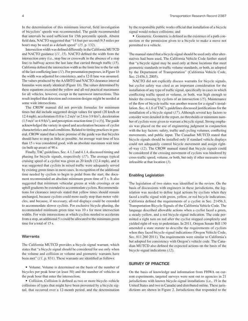
The AASHTO and California formulas estimated similar num-bers. With the default AASHTO values of perception–reaction (1 s), speed (14.7 ft/s), and acceleration (1.5 ft/s2), the first two terms of the AASHTO equation were approximately 6 s, which makes the two equations basically equivalent (Figure 1a).
For rolling cyclists, AASHTO presented an equation to determine the rolling crossing time. A cyclist who entered the intersection just at the end of green interval would have sufficient time to clear the intersection during the yellow change and all-red clearance inter-vals. Rolling time was presented as the sum of the braking distance, intersection width, and length of bicycle divided by the assumed rolling speed (suggested as 10 mph or 14.7 ft/s) as follows:
Va
W LV
= + ++ +
BCT PRT2
BDrolling
VV
a= ∗ +BD PRT
2
2
where
BCT = bicycle crossing time (s), BD = braking distance (ft), W = intersection width (ft), and a = bicycle deceleration rate for wet pavement = 5 ft/s2.
Similarly, NACTO required that an “adequate clearance inter-val (i.e., the movement’s combined time for the yellow and all-red phases) shall be provided to ensure that bicyclists entering the inter-section during the green phase have sufficient time to safely clear the intersection before conflicting movements receive a green indi-cation” (15, p. 132). An equation was provided to calculate the total clearance interval (Ci) with use of the intersection width (W) and cyclist velocity (V) as follows:
CWVi = +3
FIGURE 1 Graphical comparisons of timing formulas: (a) BMG 1 Y 1 Rclear and (b) Y 1 Rclear.
(a) (b)
4 Transportation Research Record 2387
In the determination of this minimum interval, field investigation of bicyclists’ speeds was recommended. The guide recommended that intervals be used sufficient for 15th percentile speeds. Absent field data, NACTO suggested that “14 feet per second (9.5 miles per hour) may be used as a default speed” (15, p. 132).
Intersection width was defined differently in the California MUTCD and NACTO guidance (11, 15). NACTO defined the width from the intersection entry (i.e., stop line or crosswalk in the absence of a stop line) to halfway across the last lane that carried through traffic (15). California defined the intersection width as the limit line to the far side of the last conflicting lane (11). For presentation purposes, in Figure 1b the width was adjusted for consistency, and a 12-ft lane was assumed. The values produced by the AASHTO and NACTO clearance interval formulas were nearly identical (Figure 1b). The values determined by these equations exceeded the yellow and all-red practical maximums for all vehicles, however, except in the narrowest intersections. This result implied that detection and extension designs might be needed at some wide intersections.
The CROW manual did not provide formulas for minimum times but did include suggested design values for speed (20 km/h or 12.4 mph), acceleration (0.8 to 1.2 m/s2 or 2.6 to 3.9 ft/s2), deceleration (1.5 m/s2 or 4.9 ft/s2), and perception–reaction time [1 s (3)]. The guide acknowledged the variety in speed and acceleration because of cyclist characteristics and road conditions. Related to timing practices in gen-eral, CROW stated that a basic premise of the guide was that bicycles should have to stop as little as possible. An average wait time of less than 15 s was considered good, with an absolute maximum wait time (in built-up areas) of 90 s.
Finally, TAC guidelines, Sec. 4.1.3 and 4.1.4, discussed timing and phasing for bicycle signals, respectively (17). The average typical cruising speed of a cyclist was given as 20 km/h (12.4 mph), and it was suggested that cyclists in mixed traffic were adequately served by existing green times in most cases. In recognition of the additional time needed by cyclists to begin to pedal from the start, the docu-ment recommended an absolute minimum green time of 5 s. It also suggested that minimum vehicular greens at wide crossings or on uphill gradients be extended to accommodate cyclists. Recommenda-tions for clearance intervals stated that yellow times should remain unchanged, because cyclists could more easily stop than motor vehi-cles, and because, if necessary, all-red displays could be extended to accommodate slower cyclists. For exclusive bicycle phasing, the recommended minimum green time was 10 s for most intersection widths. For wide intersections at which cyclists needed to accelerate from a stop, an additional 5 s could be allocated to the minimum green time for a total of 15 s.
Warrants
The California MUTCD provides a bicycle signal warrant, which states that “a bicycle signal should be considered for use only when the volume and collision or volume and geometric warrants have been met” (11, p. 831). These warrants are identified as follows:
• Volume. Volume is determined on the basis of the number of bicycles per peak hour (at least 50) and the number of vehicles at the peak hour that enter the intersection;
• Collision. Collision is defined as two or more bicycle–vehicle collisions of types that might have been prevented by a bicycle sig-nal, that occurred over a 12-month period, and the determination
by the responsible public works official that installation of a bicycle signal would reduce collisions; and
• Geometric. Geometric is defined as the existence of a path con-nection or the permission given to a bicycle to make a move not permitted to a vehicle.
The manual stated that a bicycle signal should be used only after alter-natives had been used. The California Vehicle Code further stated that “a bicycle signal may be used only at those locations that meet geometric standards or traffic volume standards, or both, as adopted by the Department of Transportation” (California Vehicle Code, Sec. 21456.3, 2005).
NACTO did not explicitly discuss warrants for bicycle signals, but cyclist safety was cited as an important consideration for the installation of any type of traffic signal, specifically in cases in which conflicting traffic speed or volume, or both, was high enough to hinder the crossing by cyclists of an intersection (15). Maintenance of the flow of bicycle traffic was another reason for a signal’s instal-lation. Sec. 4.1.6 of TAC’s guidelines discussed justifications for the installation of a bicycle signal (17). Although several key factors to consider were detailed in the report, no thresholds or minimum num-ber of cyclists were given to warrant a bicycle signal. Strong empha-sis was placed on the use of engineering judgment in conjunction with the key factors: safety, traffic and cycling volumes, conflicting movements, and public input. The Canadian MUTCD stated that bicycle signals should be installed only if standard vehicle displays could not adequately control bicycle movement and assign right-of-way (12). The CROW manual stated that bicycle signals could be considered if the crossing movement of cyclists was hindered by cross-traffic speed, volume, or both, but only if other measures were infeasible at that location (3).
Enabling Legislation
The legislation of two states was identified in the review. On the basis of discussions with engineers in these jurisdictions, the leg-islation was needed to define legal actions by cyclists when they faced a traffic signal with green, yellow, or red bicycle indications. California defined the requirements of a cyclist in Sec. 21456.3, Transportation Bicycle Signals of the California Vehicle Code. The language described allowable actions when a cyclist faced a green, a steady-yellow, and a red bicycle-signal indication. The code per-mitted a right turn on red after the cyclist stopped completely and yielded right-of-way to pedestrians. In 2011, Oregon Senate Bill 130 amended a state statute to describe the requirements of cyclists when they faced bicycle-signal indications (Oregon Vehicle Code, Sec. 811.260 2011). The requirements were similar to California’s but adopted for consistency with Oregon’s vehicle code. The Cana-dian MUTCD also defined the expected actions on the basis of the bicycle-signal indications (12).
SURVEY OF PRACTICE
On the basis of knowledge and information from FHWA on cur-rent experiments, targeted surveys were sent out to agencies in 21 jurisdictions with known bicycle-signal installations (i.e., 19 in the United States and two in Canada) and distributed online. These juris-dictions are shown in Figure 2. Jurisdictions that responded to the

Thompson, Monsere, Figliozzi, Koonce, and Obery 5
survey are shown with black labels; those that did not are gray. The per city response rate was 71%, including data gathered for Portland, Oregon. (It is likely that other installations of bicycle-specific signals were not captured in this survey.)
In all, 63 intersections (36 in Canada and 27 in the United States) and 149 signal heads were included in the results. The labels in Fig-ure 2 include the number of bicycle-specific signal heads reported in the survey results. Although a response from Tucson, Arizona, was collected, information about the signals in that jurisdiction was not included in the results. Tucson had designed special signal-ized intersections called “TOUCANs” that only served bicycle and pedestrian traffic on the side street approaches. With no potential to cause confusion among motorists and bicyclists, these types of signals were not the focus of this survey.
All statistics reported in this synthesis had their basis in received responses and site visits only. In this paper, the column tables labeled “Unknown” indicate that the jurisdiction did not provide this infor-mation. Because each bicycle-signal installation is unique, the analy-sis should not be construed to show consensus for any one design approach or treatment. Instead, the purpose was to highlight the cur-rent treatments and, when available, to show the variations across similar designs.
Motivation and Decision Criteria
As part of the survey, jurisdictions were asked to provide a narrative for their motivations to install bicycle signals. Reasons could be grouped into five categories as follows:
1. Cyclist noncompliance with previous traffic control,2. Presence of a contraflow bicycle movement,3. Diagonal (or otherwise unique) cyclist path through inter section,4. Safety concerns for cyclists, and5. Other.
As shown in Table 1, bicycle signals were installed most com-monly in cases in which cyclists moved against motorist traffic, took a nonstandard path through an intersection, or in cases in which concerns for cyclist safety arose at a given intersection. The many contraflow responses were from installations in Vancouver, Brit-ish Columbia, Canada, and Montreal, Quebec, Canada, with two-way cycle tracks. Reasons that fell into the “Other” category were few. For two signals, infrastructure updates gave the agencies an opportunity to install the signal. Three more signals were installed for experimental reasons.
FIGURE 2 Jurisdictions identified with bicycle-specific signals and survey respondents (co 5 county; BC = British Columbia; QC = Quebec; numbers after colons 5 reported signal heads at location; U 5 nonresponse for location; NA 5 response from Tucson on TOUCAN signals).

6 Transportation Research Record 2387
Two agencies in Portland and Eugene, Oregon, had developed warrants independently for implementation of bicycle signals. Juris-dictions in California referred to that state’s MUTCD to warrant a bicycle signal installation (11).
Physical Elements
Signal Head
Five characteristics of the bicycle signal heads were described in this synthesis: (a) backplate presence and color, (b) signal housing color, (c) lens size, (d) traits of the insignia, and (e) presence of louvers or a visibility limited indication. Table 2 presents a summary of survey results for these characteristics.
Standard signal housing colors (i.e., yellow and black) made up the majority of the signals reviewed. Eight signal heads from San Francisco,
California, were reported to be dark green (Table 2, Other row). The vast majority of bicycle signals had no backplates. When present, they reportedly varied in color from black to yellow. Pictures of the various housing and backplate combinations are shown in Figure 3f.
These elements reflected local design practice. For example, the housing color of bicycle signal heads in Vancouver (yellow) matched the motorist signals. In the survey, it was more common for U.S. jurisdictions to use different color housing for bicycles than for motor vehicle signals. Most U.S. signal lenses were 12 in. Canadian signals were more likely to be 8 in. This distinction corresponded to guidance in the Canadian MUTCD and to the fact that signal heads in Canada often were placed on both sides of the intersection (12).
To differentiate bike signals from motorist signals, many bicycle signal heads displayed an insignia (or stencil) of a bicycle in the lens. Most installed bicycle signals had some sort of insignia on the lens. There was variation in the directions in which the insignia faced.
TABLE 1 Motivations for Installation
Number of Intersections Percentage of Sample
Motivation United States Canada Total United States Canada Total
Noncompliance 3 0 3 8 na 3
Contraflow 6 36 42 17 69 48
Unique path 13 3 16 36 6 18
Safety 9 12 21 25 23 24
Other 4 1 5 11 2 6
Note: Percentages do not add to 100% because more than one motivating reason per intersection could be cited; na = not applicable.
TABLE 2 Elements of Signal Head
Number of Signal Heads Percentage of Signal Heads
Characteristic United States Canada Total United States Canada Total
Backplate color Black 18 0 18 35 na 12 Yellow 10 0 10 19 na 7 No backplate 24 97 121 46 100 81 Unknown 0 0 0 na na na
Housing color Black 32 37 69 62 38 46 Yellow 12 60 72 23 62 48 Other 8 0 8 15 na 5 Unknown 0 0 0 na na na
Lens size 12 in. 35 7 42 67 7 28 10 in. 0 0 0 na na na 8 in. 9 90 99 17 93 66 Other 2 0 2 4 na 1 Unknown 6 0 6 12 na 4
Bicycle insignia Faces left 19 79 98 37 81 66 Faces right 20 0 20 38 na 13 No insignia 12 18 30 23 19 20 Unknown 1 0 1 2 na 1
Use of louvers Yes 38 17 55 73 18 37 No 13 80 93 25 82 62 Unknown 1 0 1 2 na 1
Note: All percentages are rounded to nearest integer. Percentages based on total number of surveyed signal heads (N = 149).

Thompson, Monsere, Figliozzi, Koonce, and Obery 7
(a) (b)
(c) (d)
(f)
(e)
FIGURE 3 Various elements of bicycle-specific traffic signals: (a) mounting, (b) placement, (c) insignia, (d) detection, (e) signage, and (f) backplate and housing.
Canadian signals were more uniform in their use of a left-facing lens insignia (i.e., in Montreal and Vancouver). Variation in this respect occurred within and across U.S. cities, as did variation in the form of the insignia: a realistic outline of a bicycle and a more abstract one (Figure 3c).
Most of the signal heads surveyed did not use louvers or other modi-fiers that restricted the visibility of the bicycle signal to cyclists only. In general, when louvers were employed, it was at intersections with major safety concerns, or in cases in which the bicycle signal aligned with the motorist signal and might be easily confused. Louvers were not used heavily in either of the Canadian jurisdictions surveyed.
Placement and Mounting
In the United States, vehicle traffic signals were located on the far side of the intersection unless sight distance was an issue. This practice was followed with respect to the installation of bicycle signal heads, which were placed on both the near and far sides of intersections in about 19% of the U.S. sample and 64% of the Canadian sample (Table 3). Bicycle signals placed only on the near side are common
in Europe, but none was found in this North American survey. Typi-cally, near-side signal heads are smaller and lower in Europe. Pictures of some typical mounting locations are shown in Figure 3, a and b.
The mounting height of bicycle signals varied widely, from 7 to 19 ft (measured from pavement elevation at the bicycle stop bar). The mounting height partially correlated with the intersection placement of the signals: intersections with signals on both near and far sides tended to have lower mounting heights. Lower mounting heights also were common when the bicycle signal was mounted on the same pole as the pedestrian indication. The mounting heights reported are summarized in Table 3.
Operational Elements
Detection, Phasing, Restricted Movements, and Accompanying Signage
None of the signalized intersections in Vancouver and Montreal included detection. Of the U.S. signals, 44% were on recall with no detection. For the remaining intersections, with some form of

8 Transportation Research Record 2387
detection, loop detection was the most common. For intersections with loop detection, most used the bicycle-detector pavement mark-ing found in the MUTCD (10). Some U.S. locations also included push-button actuations (Figure 3d). The MUTCD placard sign “To Request Green” was commonly used (10). Two jurisdictions (i.e., Austin, Texas, and Portland, Oregon) reported experimentation with a detection feedback indication, which would illuminate when the controller detected the presence of a cyclist. A close-up of Portland’s installation is shown in Figure 3d.
On the basis of submitted timing plans, commentary from the sur-vey and Internet research, the phasing for most of the signals could be determined. In the United States, 59% of the intersections pro-vided an exclusive phase for bicycle movement. It also was common to restrict conflicting motor vehicle movements (70% of the inter-sections surveyed in the United States and 56% in Canada). Finally, nearly 74% of the U.S. signals included some form of accompanying
signage to provide additional information that the signal head con-trolled bicycle movements. In general, such signs were consistent (Figure 3e), although in Long Beach, California, lettering was added to the signal backplate. Some jurisdictions created guidance signs intended for cyclists, which instructed them on the use of the signal (Figure 3e). Table 4 presents a summary of survey results for these operational characteristics.
Timing of Intervals for Bicyclists
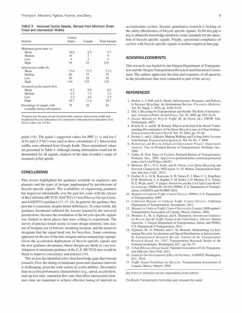
Survey respondents were asked to report the minimum green, yellow, and red times for bicycle signals (Table 5). Because a comparison of minimum times also needed to account for intersection width, these minimum times were normalized on the basis of the standing start equation for bicycle minimum green time from AASHTO’s 2012
TABLE 3 Placement and Mounting
Number of Intersections Percentage
Characteristic United States Canada Total United States Canada Total
Intersection placementa
Nearside only 0 0 0 na na na Farside only 22 13 35 81 36 56 Both 5 23 28 19 64 44 Unknown 0 0 0 na 5 na
Mounting height <10 ft 13 0 13 25 na 9 10–14.9 ft 19 93 112 37 96 75 ≥15 ft 8 4 12 15 4 8 Unknown 12 0 12 23 na 8
aPercentages based on total number of surveyed intersections (N = 63).
TABLE 4 Operational Elements
Number of Intersections Percentage of Intersections
Design Element United States Canada Total United States Canada Total
Detection type Loop 7 0 7 26 na 11 Video 2 0 2 7 na 3 Loop and push button 4 0 4 15 na 6 Push button only 2 0 2 7 na 3 No detection–recall 12 36 48 44 100 76 Unknown 0 0 0 na na na
Phasing type Exclusive 16 13 29 59 36 46 Concurrent 7 23 30 26 64 48 Leading interval 1 0 1 4 na 2 Unknown 3 0 3 11 na 5
Restricted movements Yes 19 20 39 70 56 62 No 6 16 22 22 44 35 Unknown 2 0 2 7 na 3
Accompanying signage Yes 20 9 29 74 25 46 No 6 27 33 22 75 52 Unknown 1 0 1 4 na 2
Note: Percentages based on total number of surveyed intersections (N = 63). The definition for “exclusive” includes those signals that are concurrent with pedestrian traffic but not motorist traffic.
Thompson, Monsere, Figliozzi, Koonce, and Obery 9
guide (16). The guide’s suggested values for PRT (1 s) and for L (6 ft) and (1.5 ft/s2) were used in these calculations (T). Intersection widths were obtained from Google Earth. These normalized values are presented in Table 5. Although timing information could not be determined for all signals, analysis of the data revealed a range of assumed cyclist speeds.
CONCLUSIONS
This review highlighted the guidance available to engineers and planners and the types of designs implemented by jurisdictions of bicycle-specific signals. The availability of engineering guidance has improved substantially over the past few years with the release of the California MUTCD, NACTO’s Urban Bikeway Design Guide, and AASHTO’s guidance (11, 15, 16). In general, the guidance they provide is consistent, despite minor differences. To some extent, the guidance documents reflected the lessons learned by the surveyed jurisdictions, because the installation of the bicycle-specific signals was limited to those places that were willing to experiment. The survey of practice found variety in some design elements: lens size, use of insignia, use of louvers, mounting location, and the means to designate that the signal head was for bicyclists. Some consensus appeared on the use of the lens insignia and accompanying signage. Given the accelerated deployment of bicycle-specific signals and the new guidance documents, future designs are likely to vary less. Adoption of minimum guidance in the U.S. MUTCD also would be likely to improve consistency and practice (10).
This review has identified a few clear knowledge gaps that warrant research. First, the timing of minimum green and clearance intervals is challenging, given the wide variety in cyclist abilities. Descriptive data on cyclist performance characteristics (e.g., speed, acceleration, start-up lost time, saturation flow rate) that affect intersection clear-ance time are important to achieve effective timing of intervals to
TABLE 5 Assumed Cyclist Speeds, Derived from Minimum Green Times and Intersection Widths
StatisticUnited States Canada Total Sample
Minimum green time (s) Mean 10.6 8.2 9.7 Median 10 7 9 Low 4 5 4 High 19 25 255
Intersection width (ft) Mean 77.6 77.5 77.5 Median 80 75 75 Low 30 58 30 High 110 135 135
Assumed cyclist speed (ft/s) Mean 8.2 8.8 8.5 Median 6.5 7.2 7.2 Low 2.1a 4.6 2.1a
High 18.7 17.4 18.7
Percentage of sample with available timing information
78 36 54
aExtreme low because of one location with a narrow intersection width and lengthened bicycle indication to be concurrent with pedestrian indication; next lowest value was 3.8 ft/s.
accommodate cyclists. Second, quantitative research is lacking on the safety effectiveness of bicycle-specific signals. To fill this gap is key to obtain the knowledge needed to create standards for the opera-tion of bicycle-specific signals. Finally, operational compliance of cyclists with bicycle-specific signals is another empirical data gap.
ACKNOWLEDGMENTS
This research was funded by the Oregon Department of Transporta-tion and the Oregon Transportation Research and Education Consor-tium. The authors appreciate the time and responses of all agencies in the jurisdictions that were contacted as part of the survey.
REFERENCES
1. Pucher, J., J. Dill, and S. Handy. Infrastructure, Programs, and Policies to Increase Bicycling: An International Review. Preventive Medicine, Vol. 50, Suppl. 1, 2010, pp. S106–S125.
2. Dill, J. Bicycling for Transportation and Health: The Role of Infrastruc-ture. Journal of Public Health Policy, Vol. 30, 2009, pp. S95–S110.
3. Design Manual for Bicycle Traffic (R. de Groot, ed.), CROW, Ede, Netherlands, 2007.
4. Krizek, K. J., and R. W. Roland. What Is at the End of the Road? Under-standing Discontinuities of On-Street Bicycle Lanes in Urban Settings. Transportation Research Part D, Vol. 10, 2005, pp. 55–68.
5. Pucher, J., and L. Dijkstra. Making Walking and Cycling Safer: Lessons from Europe. Transportation Quarterly, Vol. 54, No. 3, 2000.
6. Pedestrian and Bicycle Enhanced Enforcement Project: Opportunity Analysis. City of Portland Bureau of Transportation, Portland, Ore., 2004.
7. Geller, R. Four Types of Cyclists. Portland Bureau of Transportation, Portland, Ore., 2009. http://www.portlandonline.com/transportation/index.cfm?c=44597&a=158497.
8. Mekuria, M. C., P. G. Furth, and H. Nixon. Loss-Stress Bicycling and Network Connectivity. MTI report 11-19. Mineta Transportation Insti-tute, San Jose, Calif., 2012.
9. Fischer, E. L., G. K. Rousseau, S. M. Turner, E. J. Blais, C. L. Engelhart, D. R. Henderson, J. A. Kaplan, V. M. Keller, J. D. Mackay, P. A. Tobias, D. E. Wigle, and C. V. Zegeer. Pedestrian and Bicyclist Safety and Mobil-ity in Europe. FHWA-PL-10-010. FHWA, U.S. Department of Transpor-tation; AASHTO; and NCHRP, 2010.
10. Manual on Uniform Traffic Control Devices. FHWA, U.S. Department of Transportation, 2009.
11. California Manual on Uniform Traffic Control Devices. California Department of Transportation, Sacramento, 2012.
12. Manual on Uniform Traffic Control Devices for Canada (2008 update). Transportation Association of Canada, Ottawa, Ontario, 2008.
13. Monsere, C., M. A. Figliozzi, and S. Thompson. Operational Guidance for Bicycle-Specific Traffic Signals in the United States: A Review. Interim report no. 1. Oregon Department of Transportation, Salem, and FHWA, U.S. Department of Transportation, 2012.
14. Figliozzi, M., N. Wheeler, and C. M. Monsere. Methodology for Esti-mating Bicyclist Acceleration and Speed Distributions at Intersections. In Transportation Research Record: Journal of the Transportation Research Board, No. 2387, Transportation Research Board of the National Academies, Washington, D.C., pp. 66–75.
15. Urban Bikeway Design Guide. National Association of City Transporta-tion Officials, New York, 2011.
16. Guide for the Development of Bicycle Facilities. AASHTO, Washington, D.C., 2012.
17. Traffic Signal Guidelines for Bicycles. Transportation Association of Canada, Ottawa, Ontario, 2004.
Any errors or omissions are the responsibility of the authors.
The Bicycle Transportation Committee peer-reviewed this paper.