B.H.V. Topping (Editor), A Simplified Model for ... - murature · A Simplified Model for the...
17
1 Abstract In the paper a simplified model for the evaluation of the seismic behaviour of masonry buildings is presented. The proposed methodology is based on the use of a new discrete element that with a reduced computational cost, with respect to a finite element simulation, is able to simulate the non-linear behaviour of a masonry panel in its own plane and for assemblage of a masonry building. The reliability of the proposed model has been evaluated by means of non-linear push-over analyses performed on masonry walls for which are available both theoretical and experimental results. Keywords: non-linear dynamic, masonry building, seismic vulnerability, macro- models, push-over analysis, existing building. 1 Introduction The problem of the evaluation of the seismic resistance of a civil engineering structure represents a subject of high practical value but at the same time of very difficult resolution. It suffices to notice that many buildings have been constructed in regions which only subsequently have been classified as seismic areas and, as a consequence, this buildings have been designed for vertical loads only although they can be subjected to seismic loads. The social and political interest on this problem, which has been underestimated for decades, has recently grown as a consequence of repetitive dramatic building failures associated to even modest earthquake events. In Italy this dramatic events have led to a total revision of the seismic codes and a to a new classification of the seismic zones. Such an upgrade, which is obviously valuable, at the same time introduce new and complex problems which are urged to be solved in the structural engineering practice. In fact, in order to estimate the seismic vulnerability of an existing building and to establish if a structure require a seismic upgrade a structural engineer, that is not a researcher, needs adequate tools Paper 195 A Simplified Model for the Evaluation of the Seismic Behaviour of Masonry Buildings I. Caliò, M. Marletta and B. Pantò Department of Civil and Environmental Engineering University of Catania, Italy Civil-Comp Press, 2005. Proceedings of the Tenth International Conference on Civil, Structural and Environmental Engineering Computing, B.H.V. Topping (Editor), Civil-Comp Press, Stirling, Scotland.
Transcript of B.H.V. Topping (Editor), A Simplified Model for ... - murature · A Simplified Model for the...
1
Abstract In the paper a simplified model for the evaluation of the seismic behaviour of masonry buildings is presented. The proposed methodology is based on the use of a new discrete element that with a reduced computational cost, with respect to a finite element simulation, is able to simulate the non-linear behaviour of a masonry panel in its own plane and for assemblage of a masonry building. The reliability of the proposed model has been evaluated by means of non-linear push-over analyses performed on masonry walls for which are available both theoretical and experimental results. Keywords: non-linear dynamic, masonry building, seismic vulnerability, macro-models, push-over analysis, existing building. 1 Introduction The problem of the evaluation of the seismic resistance of a civil engineering structure represents a subject of high practical value but at the same time of very difficult resolution. It suffices to notice that many buildings have been constructed in regions which only subsequently have been classified as seismic areas and, as a consequence, this buildings have been designed for vertical loads only although they can be subjected to seismic loads. The social and political interest on this problem, which has been underestimated for decades, has recently grown as a consequence of repetitive dramatic building failures associated to even modest earthquake events. In Italy this dramatic events have led to a total revision of the seismic codes and a to a new classification of the seismic zones. Such an upgrade, which is obviously valuable, at the same time introduce new and complex problems which are urged to be solved in the structural engineering practice. In fact, in order to estimate the seismic vulnerability of an existing building and to establish if a structure require a seismic upgrade a structural engineer, that is not a researcher, needs adequate tools
Paper 195 A Simplified Model for the Evaluation of the Seismic Behaviour of Masonry Buildings I. Caliò, M. Marletta and B. Pantò Department of Civil and Environmental Engineering University of Catania, Italy
Civil-Comp Press, 2005. Proceedings of the Tenth International Conference on Civil, Structural and Environmental Engineering Computing, B.H.V. Topping (Editor), Civil-Comp Press, Stirling, Scotland.

2
and sufficient knowledge that at the present time generally does not possess because, for background and experience, he was not needed to acquire. This problematic regards all civil engineering structures and with reference to buildings is mainly concerned to concrete and masonry structures. In the last decades many advances have been made for the evaluation of the seismic vulnerability of steel and reinforced concrete buildings and a great part of these progresses has been implemented in commercial structural engineering programs that can now be used in practical engineering. However, the same progresses have not been obtained for masonry buildings and nowadays the simulation of the nonlinear dynamic behaviour of a masonry structure still represents a very difficult problem which requires the use of high computational cost finite element models and very expertise judgement. For this reason, in the recent years, many authors developed simplified methodologies that, with a reduced computation effort, if compared with a nonlinear finite element simulation, should be able to simulate the non-linear seismic behaviour of masonry buildings and to provide results sufficiently accurate for engineering practice purposes. These methodologies are based on the use of simplified models [1÷5] which are able to describe the behaviour of a masonry portion and for assemblage of a masonry structure, some of these methodologies are based on the use of equivalent frame models [6,7]. The aim of the present work is to define a new advanced computational tool for the simulation of the seismic behaviour and the evaluation of the vulnerability of masonry buildings which is also applicable in the current engineering practice. To this purpose, starting from the simplified models available in the literature and from the experience maturated on the modelling of reinforced concrete walls [8], a discrete model of a portion of masonry wall has been introduced. This equivalent model, macro-element, is able to get the nonlinear behaviour of an entire masonry wall and of a whole building as an assemblage of several walls; the computational cost is strongly reduced if compared to a traditional finite element modelling. It is apparent that the effectiveness of such a macro-modelling is strongly dependent on the correct definition of the parameters so that the equivalence between the continuum and the discrete models is enforced. The single macro-element has been conceived with the purpose of represent a whole masonry pier; nevertheless, the model of the masonry pier could be also realised by a mesh of macro-elements. The macro-element has been designed to simulate the nonlinear mechanical behaviour of a portion of wall, including the limited tension and shear strength and accounting for the main failure mechanisms. The effectiveness of the proposed modelling has been evaluated by means of incremental static analyses carried out on masonry panels and walls which have been the object of theoretical and experimental research in the past.
2 The proposed discrete-element The basic element of the proposed simplified approach has a simple and easy-comprehensive mechanical scheme, Figure 1. It is represented by an articulated quadrilateral constituted by four rigid edges connected by four hinges and

3
two diagonal non-linear springs; in the following we call the quadrilateral as panel. Each side of the panel interact with other panels or with external elements or supports by means of a discrete distributions of non-linear springs which we call interfaces. Each interface is constituted by n+1 springs, the n transversal springs act orthogonally to the panel side, the sliding spring controls the relative motion in the direction of the panel surfaces.
(a) (b)
Figure 1: A portion of masonry wall modelled as a mesh of panel elements. (a) Undeformed configuration; (b) deformed configuration.
Such a simplified scheme is able to simulate the main collapse mechanisms of a portion of masonry wall subjected to horizontal loads and vertical loads in its own plane. These collapse mechanisms, namely the flexural failure, the diagonal shear failure and sliding shear failure are roughly represented in Figure 2 in which the main location of cracks together with the kinematics are indicated. In Figure 3 it is shown how the proposed discrete element allows a simply and realistic simulation of the kinematics associated to the failure mechanisms that must be controlled by specific non-linear springs. It is worth to notice that, in order to obtain reasonable results, for each failure mechanism a suitable resistance criteria must be considered and well calibrated with the experimental results. The flexural failure collapse is associated to the rocking of the masonry panel in its own plane; the lost of the bearing capacity in this case is related to progressive rupture of the panel in the traction zone and/or to the crushing of the panel in the compression zone, Figure 2a. This collapse mechanism can be simulated by the considered discrete-element and can be conveniently controlled by the transversals springs of the interface whose role is to concentrate the axial and flexural deformability of the masonry panel and to predict the corresponding failure mechanisms (Figure 3a). The diagonal-shear failure collapse is associated to the lost of the bearing capacity of masonry panel due to excessive shear and the consequent formation of inclined diagonal cracks along the direction of principal stresses. Using the discrete-element this shear-collapse mechanism can be controlled by means of the diagonal springs that have exactly the role of simulate and predict the non-linear shear response of the panel (Figure 3b).

4
The sliding-shear failure collapse is associated to the sliding of the masonry panel in its own plane. In this case the corresponding lost of the bearing capacity is associated to the formation of horizontal cracks in the bed-joints, Figure 2c. This failure mode, that generally occurs for low level of vertical loads and low values of friction coefficients, can be controlled through the longitudinal interface non-linear springs.
(a) (b) (c)
Fq
Fq
Fq
Figure 2: Main in-plane failure mechanisms of a masonry panel;
(a) flexural failure; (b) shear-diagonal failure; (c) shear-sliding failure.
FFF
(c)(b)(a)
qq q
Figure 3: Simulation of the main in-plane failure mechanisms of a masonry panel by means of the proposed macro-element: (a) flexural failure; (b) shear-diagonal
failure; (c) shear-sliding failure. Although the proposed simplified model has been conceived in order to simulate the behaviour of an entire masonry wall, it can also simulate the nonlinear behaviour of a masonry portion and as a consequence allows the modelling of a masonry wall as a mesh of macro-elements. In some cases a mesh of macro-elements can be useful to obtain a more detailed response (i.e. interface stress distribution) or to get an insight into the kinematics failure mechanism of the structure. In the following paragraphs, the kinematical and mechanical characteristics of the panel and of the interface are described. Then a proposal for the calibration of the mechanical parameters of the model is presented.
2.1 The kinematics A discrete element model can be regarded as an assemblage of panels reciprocally connected by interfaces. A simply example of a masonry wall modelled by means of

5
the proposed methodology is represented in figure 4. It is worth to notice that, with the proposed procedure, the masonry wall is assimilated to an equivalent mechanical scheme in which the physical role of each element is well clear and therefore the implementation of the model can be done also by using a large purpose finite element program. The model can also be refined by using more panels in order to better describe the kinematics of the masonry wall.
void
void
void
void
Figure 4: Masonry wall and corresponding discrete equivalent schemes. The degrees of freedom of the structural scheme are associated to the in-plane motion of the panels. Each panel exhibits three degrees of freedom, associated to the in-plane rigid body motion, plus a further degree of freedom needed for description of the panel deformability. Hence the total degrees of freedom of a n panels structural scheme are 4n. As Lagrangian parameters the four displacements of the rigid edges along their own directions have been chosen, as reported Figure 5 in which the corresponding dual forces are also represented. The deformations in the interfaces are associated to the relative motion between the corresponding panels and does not need any further Lagrangian parameter. The complete kinematics of a generic interface is dependent by six degrees-of-freedom, needed for the description of the motion of the two connected rigid sides of the panels. If the interface connects a panel to an elastic external support (i.e. a deformable soil) three degrees-of-freedom are relative to the panel side while the other three pertain to the elastic restraint that simulate the soil deformability.

6
u3
u1
2uu4
1u u3
u2 u4
1F
F4
F3
F2
(a) (b) (c)
Figure 5: (a) Chosen Lagrangian parameters for the panel; (b) deformed configurations corresponding to the activation of each degree-of-freedom; (c) dual
forces corresponding to the Lagrangian parameters.
A schematic representation of an interface is reported in Figure 6 where, for the sake of clarity only, the interface is represented with a finite thickness although in the analytical model interfaces do not have thickness.
Panel k
Panel l
node jξ
η
node ijoint d
joint c
joint b
joint a
same position in the initial configuration
same position in the initial configuration
zero thickness Interface (a)
. . . kn/2kn-1kn/2+1
kn
kh
Transversal springs
Longitudinal spring
kn-2 k1k2k3. . .
λ/2 λ λ
node jnode i
node i node j
(b)
Figure 6: Interface which connect two panels: (a) local reference system and
identification of nodes and panels; (b) interface springs.

7
For simplicity, each interface has been identified by two nodes i and j, Figure 6a. Each node actually is associated to two joints of the model, each belonging to one of the two panels connected by the interface. Therefore in the initial undeformed configuration, corresponding to a zero stress condition, the two distinct joints corresponding to the same node share the same position. 2.3 Calibration of the non-linear springs It has been shown that the kinematics of the model is able to simulate the main failure mechanisms of a masonry element. However the effectiveness of the simulation of the non-linear behaviour is strongly dependent on an suitable definition of the parameters of the model that should lead to a reasonable equivalence between the masonry wall and its simplified non-linear mechanical representation. This equivalence can be enforced using different approaches and different collapse criteria. The approach considered herein is based on a mechanical equivalence between the discrete model and reference continuous models characterized by simple but reliable constitutive laws. The aim is to obtain a calibration approach based only on the mechanical characteristics of the masonry that must be assimilated to an equivalent homogeneous media. To this purpose, different continuous models of the masonry are considered and the equivalence between the macro-model and the continuous models is enforced by simple physical considerations. Namely a local constitutive law for each aspect of the non-linear mechanical behaviour and the relative failure mechanisms will be defined. Following this approach each spring will inherit an uni-axial nonlinear force-displacement law from the continuous model chosen for the description of the mechanical behaviour that the spring contribute to simulate. It is worth to notice that the proposed model allows a physically consistent characterisation of the masonry structure, since all the parameters of the model can be calibrated by means of the usually adopted masonry mechanical parameters that can be obtained by the standard laboratory and in situ tests [9] or can be assumed by the expertise judgment on the base of the knowledge of similar masonry structures. 2.3.1 Calibration of the transversal springs of the interface Since the masonry is considered as an homogeneous media, without any differentiation between bricks or stone elements and mortar joints, the global behaviour can be ascribed to its flexural and shearing characteristics. The flexural behaviour is simulated by the transversal springs of the interfaces which connect the panel with other elements and/or external supports. In these nonlinear springs all the flexural properties of the portion of masonry which the panel represents are lumped. In the applications reported in the following each transversal spring has been calibrated by assuming a non-symmetric elasto-plastic behaviour with limited deformability. The orthotropic nature of the masonry, represented by the panel and the interface, can be simply considered by calibrating the horizontal and vertical interfaces according to the mechanical properties of the corresponding orthogonal

8
directions. Considering the general case in which an horizontal interface connects to panels characterized by different properties, the vertical transversal springs must simulate the deformability of the two panels in the vertical directions. The stiffness calibration can be simply obtained by considering the influence area of each panel and concentrating the corresponding stiffnesses in two different springs that put in series give the resulting spring of the interface, Figure 7. Therefore each spring is simply calibrated by enforcing the equivalence between the spring and the axial rigidity of the masonry strip which pertains to it. That masonry strip (influence area) is as wide as the span between two consecutive springs λ and as high as the half-dimension of the panel in the direction perpendicular to the interface L/2, Figure 7.
F
uu
spring 1Panel k
Panel l
Panel k
Panel l
spring 2
single spring equivalent to springs 1 and 2 in series
L 1
L /21
L /22
L 2
ty1
ty1 tu1
Fcy1
cy1u cy1u
ucy2 cy2
Fty2
Fcy2
ty2 tu2uu
u
F
u
F
u
influence area
λ
zero thickness
influence area
Figure 7: Calibration of the Interface transversal springs.
With reference to a single panel, according to the above described simply procedure, the initial stiffness (Kp), the elastic yielding strengths (Fcy, Fty) and the ultimate displacements (ucu, utu) for compression and tension are derived by the knowledge of the mechanical material properties of the masonry part that the considered panel has the role to represent.
L
sEK pλ2= (1)
ccy sF σλ= ; tty sF σλ= (2 a,b)
cucuLu ε2
= ; tutuLu ε2
= (3 a,b)
where: E is the Young’s modulus in the direction orthogonal to the interface; σc and σt are the compression and traction yielding stresses, εcu and εtu are the ultimate

9
compression and traction strains; L is the dimension of the panel in the direction orthogonal to the interface; s is the thickness of the represented masonry; λ is the span between two consecutive springs. Once the mechanical properties of the springs corresponding to both panels have been defined it is necessary to combine the two obtained nonlinear springs in a single resulting spring. This require the definition of the stiffness, the yielding strengths and the ultimate displacements for the resulting spring that actually represent an interface spring. As it is well-known, the stiffness equivalent to two springs in series is given by
1 2
1 2
p p
p p
K KK
K K⋅
=+
(4)
The yielding strength of the resultant spring is obviously equal to the minimum between the yielding strengths of the two springs in series. The ultimate displacements for compression and tension can be obtained by adding the ultimate displacement of the spring that yields at first and the displacement attained at the same force by the other spring that remain elastic; namely:
2
2
cyFcu cu F
tyFtu tu F
FLUKFLU
K
ε
ε
= ⋅ +
= ⋅ +
(5 a,b)
where: εtu
Fmin and εcuFmin are the ultimate tension and compression strains of the
spring which owns the minimum yielding strength (Ftymin), and KFmax is the stiffness
of the spring which owns the maximum yielding strength. When the limit displacement of a spring is attained, a fragile rupture is experienced; this means that the spring is instantaneously unloaded and the force previously carried by the spring is redistributed to the other elements. A different behaviour for rupture in compression and in tension has been provided. In fact when a spring reaches the limit displacement in compression after the unloading it is totally removed from the model. When a spring attains the limit displacement in tension, it will be no more able to carry tension forces but it can bear compressive loads once the contact between the elements is restored.
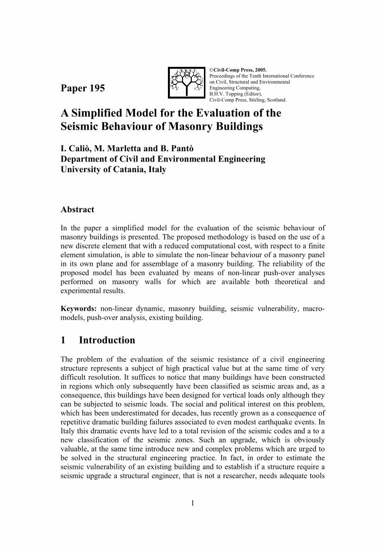
2.3.2 Calibration of the sliding spring of the interface The sliding spring has the role of simulating the potential sliding between the two elements connected by the interface. The characteristics of that spring depends on the contact surface between the two elements and therefore on the state of the transversal springs. Namely, when the contact surface between the elements reduces to zero the sliding spring has no more effect. This spring is characterised by a rigid-plastic constitutive law with a Mohr-Coulomb yielding surface. The yielding limit force has been assumed as a linear function of the resultant normal strength N which
10
acts on the interface by means of a friction coefficient µ and a cohesion force Fo, Figure 8. NFF o µ+=lim (6)
friction sliding surface
N
µ, F0
N µ
Ν
Flim
F
F
F0
(a) (b)
Figure 8: (a) Rehologic model for the sliding behaviour of the interface; (b) Coulomb yielding surface.
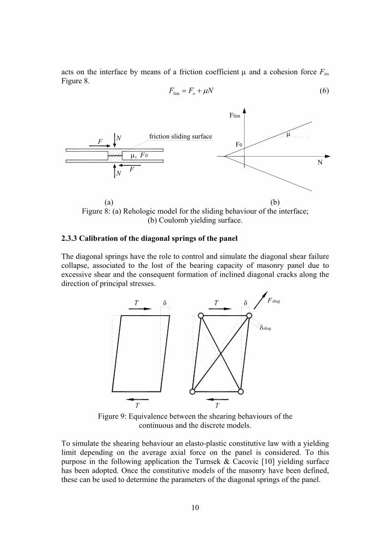
2.3.3 Calibration of the diagonal springs of the panel The diagonal springs have the role to control and simulate the diagonal shear failure collapse, associated to the lost of the bearing capacity of masonry panel due to excessive shear and the consequent formation of inclined diagonal cracks along the direction of principal stresses.
T
T
δdiag
δ Fdiagδ
T
T
Figure 9: Equivalence between the shearing behaviours of the
continuous and the discrete models. To simulate the shearing behaviour an elasto-plastic constitutive law with a yielding limit depending on the average axial force on the panel is considered. To this purpose in the following application the Turnsek & Cacovic [10] yielding surface has been adopted. Once the constitutive models of the masonry have been defined, these can be used to determine the parameters of the diagonal springs of the panel.

11
The calibration of these parameters consists of a force and displacement equivalence between a masonry wall, considered as a homogeneous solid deformable only for shear, and the discrete model, given by the articulated quad with the two diagonal springs (Figure 9). The ultimate displacement of the wall (δu) has been assumed, according to Magenes and Calvi [11], in terms of the ultimate angular deformation (γu) of the masonry: %./ 530== pultimoultimo Hδγ (7) where Hp is the height of the considered panel. Once the ultimate shear strength and displacement are known, the corresponding parameters of the diagonal springs are obtained by means of simply equilibrium and compatibility conditions.
3 Numerical applications In this section the proposed macro-model is employed to simulate the response of masonry walls for which numerical and/or experimental results are available from previous surveys. Namely the results of static incremental analyses are presented and compared with those already presented in the literature. The case presented herein is relative to a masonry wall belonging to an existing five storey building in Catania (South-East Sicily) designed and built for vertical loads only.
Figure 10: Typical floor plan of the considered building in which
the analysed wall is hatched. For the considered wall numerical results obtained with different models are available in the literature since the building has been taken as a case study in a research programme called “Catania Project” coordinated by the GNDT (Italian National Group for the Defence against Earthquakes) [12]. In this programme the considered building has been chosen as representative of many recent Italian masonry buildings, characterised by sufficient-rigid floor and reinforced concrete
12
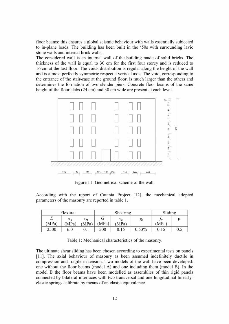
floor beams; this ensures a global seismic behaviour with walls essentially subjected to in-plane loads. The building has been built in the ‘50s with surrounding lavic stone walls and internal brick walls. The considered wall is an internal wall of the building made of solid bricks. The thickness of the wall is equal to 30 cm for the first four storey and is reduced to 16 cm at the last floor. The voids distribution is regular along the height of the wall and is almost perfectly symmetric respect a vertical axis. The void, corresponding to the entrance of the stair-case at the ground floor, is much larger than the others and determines the formation of two slender piers. Concrete floor beams of the same height of the floor slabs (24 cm) and 30 cm wide are present at each level.
174 273 256203 330 160 440370 13022
516
322
514
522
514
522
514
522
5
122
1900
Figure 11: Geometrical scheme of the wall.
According with the report of Catania Project [12], the mechanical adopted parameters of the masonry are reported in table 1.
Flexural Shearing Sliding
E (MPa)
σc (MPa)
σt (MPa)
G (MPa)
τk (MPa)
γu
fo (MPa)
µ
2500 6.0 0.1 500 0.15 0.53% 0.15 0.5
Table 1: Mechanical characteristics of the masonry. The ultimate shear sliding has been chosen according to experimental tests on panels [11]. The axial behaviour of masonry as been assumed indefinitely ductile in compression and fragile in tension. Two models of the wall have been developed: one without the floor beams (model A) and one including them (model B). In the model B the floor beams have been modelled as assemblies of thin rigid panels connected by bilateral interfaces with two transversal and one longitudinal linearly-elastic springs calibrate by means of an elastic equivalence.

13
In the analyses the static vertical forces due to the self weight of the structure and to the accidental loads have been considered, together with an incremental distribution of horizontal forces proportional to the floor masses and heights as reported in Table 2. Both vertical and horizontal loads calculated for a given floor have been distributed equally and applied to all the elements of that floor. Namely in the model A the loads have been applied to the panels while in the model B the loads have been applied to the floor beams.
Elevation 1 2 3 4 5 Vertical load (kN) 785.60 859.60 859.60 746.05 183.50 Floor height (cm) 452 822 1192 1562 1910 Horizontal load (kN) 156.30 311.00 439.65 512.90 154.40
Table 2: Vertical and horizontal load distributions.
In the following the results of the nonlinear static analyses conducted with the proposed macro-model are reported. The obtained capacity curve and collapse mechanism have been put in comparison with the numerical results obtained by other authors using different models. Namely a finite element model with damage layers performed (Gambarotta e Lagomarsino [13]) and a simplified model, based on the definition of an equivalent frame (Magenes and Calvi [6,7]) have been considered. The FE model by Gambarotta e Lagomarsino, even if retains all the drawbacks of a finite element modelling (i.e. the computational cost), is presented as the more effective means of numerical investigation for masonry structures. The simplified method based on the definition of an equivalent frame, called SAM method, provides the great advantage of modelling a wall by means of frame elements and includes the likely collapse mechanisms of the piers and of the spandrels by assigning appropriate failure domains.
0 10 20 30 40 50 60 70 800
200
400
600
800
1000
1200
top displacement (mm)
base
she
ar (k
N)
Proposed macro-modelFE modelSAM model
Figure 12: Comparison between the push-over curves for the models without floor
beams.
14
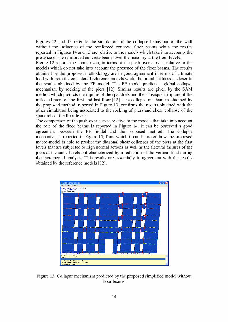
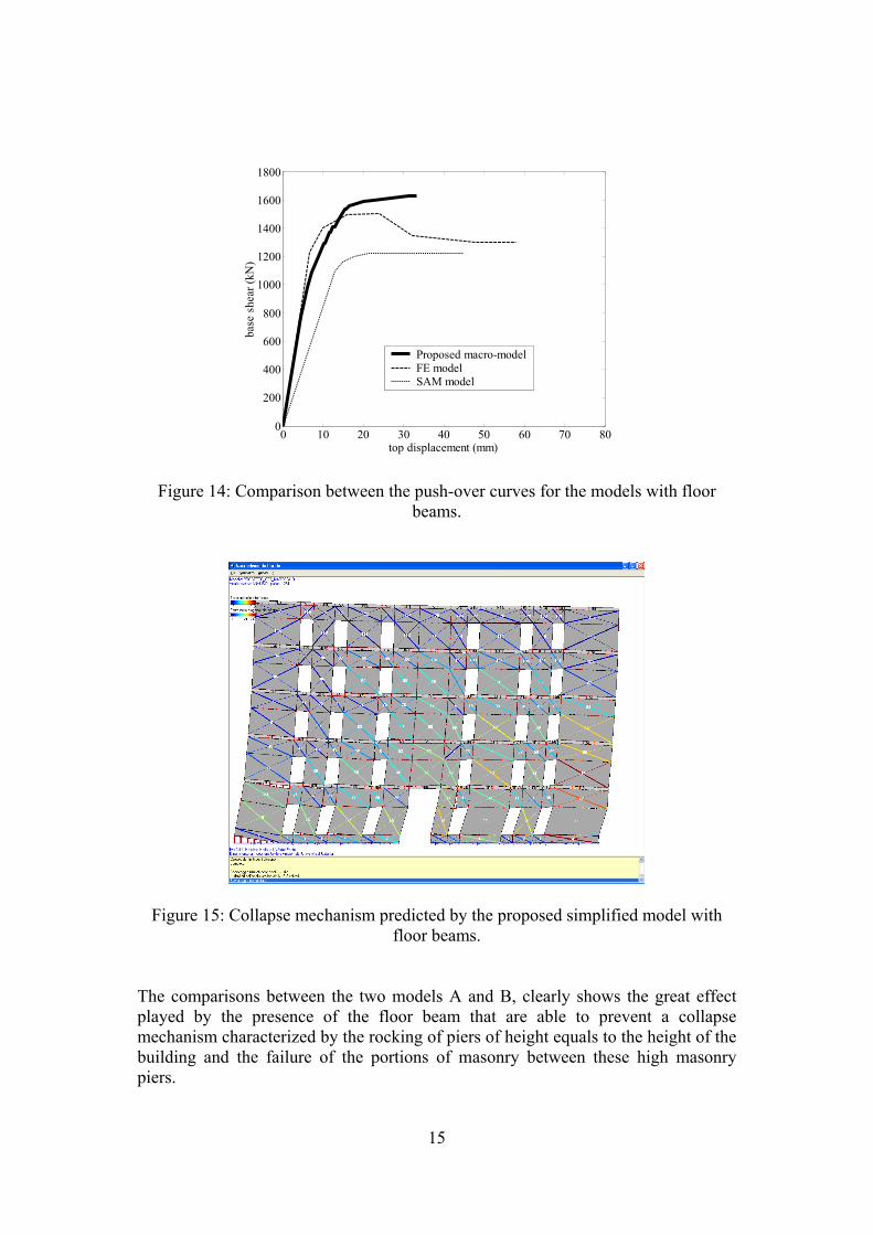
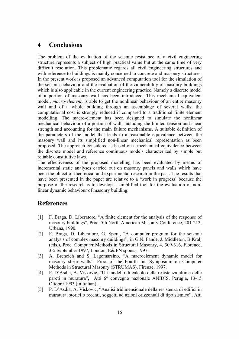
Figures 12 and 13 refer to the simulation of the collapse behaviour of the wall without the influence of the reinforced concrete floor beams while the results reported in Figures 14 and 15 are relative to the models which take into accounts the presence of the reinforced concrete beams over the masonry at the floor levels. Figure 12 reports the comparison, in terms of the push-over curves, relative to the models which do not take into account the presence of the floor beams. The results obtained by the proposed methodology are in good agreement in terms of ultimate load with both the considered reference models while the initial stiffness is closer to the results obtained by the FE model. The FE model predicts a global collapse mechanism by rocking of the piers [12]. Similar results are given by the SAM method which predicts the rupture of the spandrels and the subsequent rupture of the inflected piers of the first and last floor [12]. The collapse mechanism obtained by the proposed method, reported in Figure 13, confirms the results obtained with the other simulation being associated to the rocking of piers and shear collapse of the spandrels at the floor levels. The comparison of the push-over curves relative to the models that take into account the role of the floor beams is reported in Figure 14. It can be observed a good agreement between the FE model and the proposed method. The collapse mechanism is reported in Figure 15, from which it can be noted how the proposed macro-model is able to predict the diagonal shear collapses of the piers at the first levels that are subjected to high normal actions as well as the flexural failures of the piers at the same levels but characterized by a reduction of the vertical load during the incremental analysis. This results are essentially in agreement with the results obtained by the reference models [12].
Figure 13: Collapse mechanism predicted by the proposed simplified model without
floor beams.
15
0 10 20 30 40 50 60 70 800
200
400
600
800
1000
1200
1400
1600
1800
top displacement (mm)
base
she
ar (k
N)
Proposed macro-modelFE modelSAM model
Figure 14: Comparison between the push-over curves for the models with floor beams.
Figure 15: Collapse mechanism predicted by the proposed simplified model with floor beams.
The comparisons between the two models A and B, clearly shows the great effect played by the presence of the floor beam that are able to prevent a collapse mechanism characterized by the rocking of piers of height equals to the height of the building and the failure of the portions of masonry between these high masonry piers.
16
4 Conclusions The problem of the evaluation of the seismic resistance of a civil engineering structure represents a subject of high practical value but at the same time of very difficult resolution. This problematic regards all civil engineering structures and with reference to buildings is mainly concerned to concrete and masonry structures. In the present work is proposed an advanced computation tool for the simulation of the seismic behaviour and the evaluation of the vulnerability of masonry buildings which is also applicable in the current engineering practice. Namely a discrete model of a portion of masonry wall has been introduced. This mechanical equivalent model, macro-element, is able to get the nonlinear behaviour of an entire masonry wall and of a whole building through an assemblage of several walls; the computational cost is strongly reduced if compared to a traditional finite element modelling. The macro-element has been designed to simulate the nonlinear mechanical behaviour of a portion of wall, including the limited tension and shear strength and accounting for the main failure mechanisms. A suitable definition of the parameters of the model that leads to a reasonable equivalence between the masonry wall and its simplified non-linear mechanical representation as been proposed. The approach considered is based on a mechanical equivalence between the discrete model and reference continuous models characterized by simple but reliable constitutive laws. The effectiveness of the proposed modelling has been evaluated by means of incremental static analyses carried out on masonry panels and walls which have been the object of theoretical and experimental research in the past. The results that have been presented in the paper are relative to a ‘work in progress’ because the purpose of the research is to develop a simplified tool for the evaluation of non-linear dynamic behaviour of masonry building. References [1] F. Braga, D. Liberatore, “A finite element for the analysis of the response of
masonry buildings”, Proc. 5th North American Masonry Conference, 201-212, Urbana, 1990.
[2] F. Braga, D. Liberatore, G. Spera, “A computer program for the seismic analysis of complex masonry duildings”, in G.N. Pande, J. Middleton, B.Kralj (eds.), Proc. Computer Methods in Structural Masonry, 4, 309-316, Florence, 3-5 September 1997, London, E& FN spons., 1997.
[3] A. Brencich and S. Lagomarsino, “A macroelement dynamic model for masonry shear walls”. Proc. of the Fourth Int. Symposium on Computer Methods in Structural Masonry (STRUMAS), Firenze, 1997.
[4] P. D’Asdia, A. Viskovic, “Un modello di calcolo della resistenza ultima delle pareti in muratura”, Atti 6° convegno nazionale ANIDIS, Perugia, 13-15 Ottobre 1993 (in Italian).
[5] P. D’Asdia, A. Viskovic, “Analisi tridimensionale della resistenza di edifici in muratura, storici o recenti, soggetti ad azioni orizzontali di tipo sismico”, Atti

17
del Convegno nazionale “La meccanica delle murature tra teoria e progetto”, Messina, 18-20 Settembre 1996, 463-472. Bologna, Pitagora Editrice, 1996 (in Italian).
[6] G. Magenes and G.M. Calvi, “Prospettive per la calibrazione di metodi semplificati per l’analisi sismica di pareti murarie”, Convegno nazionale “La meccanica delle murature tra teoria e progetto”, Messina, 18-20 Settembre, 1996 (in Italian).
[7] G. Magenes, D. Bolognini, C. Braggio (eds), “Metodi semplificati per l'analisi sismica non lineare di edifici in muratura”, CNR-Gruppo Nazionale per la Difesa dai Terremoti, Roma, 2000, 99 pages (in Italian)
[8] I. Caliò, M. Marletta, “Seismic Performance of a Reinforced Concrete building not designed to withstand Earthquake Loading”. Chapter 16 in Seismic Prevention of Damage for Mediterranean Cities A Case History: The city Catania (Italy), editor M. Maugeri, WIT press, Southampton (UK), in press (2004).
[9] C. Modena, F. Pineschi, M.R. Valluzzi (eds), “Valutazione della vulnerabilità sismica di alcune classi di strutture esistenti - Sviluppo e valutazione di metodi di rinforzo”, CNR-Gruppo Nazionale per la Difesa dai Terremoti, Roma, 2000 (in Italian).
[10] V. Turnsek, F. Cacovic, “Some experimental result on the strength of brick masonry walls”, Proc. 2nd Int. Brick Masonry Conference, 149-156. Stoke-on-Trent, 1971.
[11] G. Magenes and G.M. Calvi, “In plane seismic response of brick masonry walls”, Earthquake Engineering and structural Dynamics, 26, 1091-1112 (1997).
[12] D. Liberatore, (ed), “Indagine sulla risposta sismica di due edifici in muratura”, CNR (Italian National Group for the Defence against Earthquakes), Roma, 2000 (in Italian).
[13] L. Gambarotta and S. Lagomarsino, “Damage models for the seismic response of brick masonry shear walls. Part II: The continuum model and its application”, Earthquake Engineering and Structural Dynamics, 26, 440-462, 1997.