Bharat Heavy Electricals Limited do… · Bharat Heavy Electricals Limited (High Pressure Boiler...
27
Bharat Heavy Electricals Limited (High Pressure Boiler Plant) Tiruchirappalli – 620014, TAMIL NADU, INDIA An ISO 9001 CAPITAL EQUIPMENT / MATERIALS MANAGEMENT Company Page 1 of 1 ENQUIRY NOTICE INVITING TENDER Phone: +91 431 257 79 38 Fax : +91 431 252 07 19 Email : [email protected] Web : www.bhel.com TWO PART BID Tender to be submitted in two Parts Enquiry Number: 2621000139 Enquiry Date: 10.11.2010 Due date for submission of quotation: 10.12.2010 You are requested to quote the Enquiry number date and due date in all your correspondence. This is only a request for quotation and not an order. Please note that under any circumstances both delayed offer and late offers will not be considered. Hence vendors are requested to ensure that the offer is reaching physically our office before 14.00 hrs on the Date of tender opening. Item Description Quantity 10 Pipe to Pipe / Pipe to Fittings Butt – Joint Welding Station as per the technical specification & commercial conditions applicable (to be downloaded from web site www.bhel.com or http://tenders.gov.in ) 3 No. Important points to be taken care during submission of offer 1. Checklist to be filled and enclosed along with the offer failing which, the offer will not be considered for evaluation. 2. All updates, amendments, corrigenda, etc., (if any), for each tender will be posted only on the above websites from time to time, as and when required, until each tender is opened. There will be no publication of such updates, amendments, corrigenda, etc., through newspapers or any other media. BHEL’s General guidelines / instructions (refer MM/CE/GT/001) including bank guarantee formats and list of consortium banks, commercial terms check-list can be downloaded from BHEL web site http://www.bhel.com or from the Government tender website http://tenders.gov.in (public sector units > Bharat Heavy Electricals Limited page) under Enquiry reference “2621000139”. Tenders should reach us before 14:00 hours on the due date Tenders will be opened at 14:30 hours on the due date Tenders would be opened in presence of the tenderers who have submitted their offers and who may like to be present Yours faithfully, For BHARAT HEAVY ELECTRICALS LIMITED Sr.Manager / Capital Equipment / MM
Transcript of Bharat Heavy Electricals Limited do… · Bharat Heavy Electricals Limited (High Pressure Boiler...

Bharat Heavy Electricals Limited (High Pressure Boiler Plant) Tiruchirappalli – 620014, TAMIL NADU, INDIA An ISO 9001 CAPITAL EQUIPMENT / MATERIALS MANAGEMENT Company
Page 1 of 1
ENQUIRY NOTICE INVITING TENDER
Phone: +91 431 257 79 38 Fax : +91 431 252 07 19 Email : [email protected] Web : www.bhel.com
TWO PART BID Tender to be submitted in two Parts
Enquiry Number: 2621000139
Enquiry Date: 10.11.2010
Due date for submission of quotation:
10.12.2010
You are requested to quote the Enquiry number date and due date in all your correspondence. This is only a request for quotation and not an order. Please note that under any circumstances both delayed offer and late offers will not be considered. Hence vendors are requested to ensure that the offer is reaching physically our office before 14.00 hrs on the Date of tender opening.
Item Description Quantity 10 Pipe to Pipe / Pipe to Fittings Butt – Joint
Welding Station as per the technical specification & commercial conditions applicable (to be downloaded from web site www.bhel.com or http://tenders.gov.in)
3 No.
Important points to be taken care during submission of offer
1. Checklist to be filled and enclosed along with the offer failing which, the offer will not be considered for evaluation.
2. All updates, amendments, corrigenda, etc., (if any), for each tender will be posted only on the above websites from time to time, as and when required, until each tender is opened. There will be no publication of such updates, amendments, corrigenda, etc., through newspapers or any other media.
BHEL’s General guidelines / instructions (refer MM/CE/GT/001) including bank guarantee formats and list of consortium banks, commercial terms check-list can be downloaded from BHEL web site http://www.bhel.com or from the Government tender website http://tenders.gov.in (public sector units > Bharat Heavy Electricals Limited page) under Enquiry reference “2621000139”. Tenders should reach us before 14:00 hours on the due date Tenders will be opened at 14:30 hours on the due date Tenders would be opened in presence of the tenderers who have submitted their offers and who may like to be present
Yours faithfully, For BHARAT HEAVY ELECTRICALS LIMITED
Sr.Manager / Capital Equipment / MM

S-115-TMM-19(3)-Part-A
Page 1 of 4
PART A QUALIFYING CRITERIA FOR THE SUPPLY OF
PIPE to PIPE/PIPE to FITTINGS BUTT-JOINT WELDING STATION
SECTION – I The BIDDER is expected to give complete details against each clause in the table given below, with additional sheets those may be attached (giving clear reference number) to furnish and cover the requisite details / documents.
S. No. PARTICULARS VENDOR’s RESPONSE 1.0 Profile of the Company bringing-out the
years of Experience of the BIDDER in the field of machine design , manufacture and supply of CUSTOM BUILT PIPE BUTT-JOINT WELDING STATION having column & boom type welding machine, job handling manipulator and support roller stand, etc.
2.0 Number of BUTT WELDING STATIONS supplied, installed and commissioned till date (with details on machine type, configuration, customer and quantity)
3.0 YEAR of supply of latest PIPE BUTT WELDING STATION and the Technical Specifications of the Machine supplied.
4.0 Number of BUTT WELDING STATIONS supplied, installed and commissioned till date for the CUSTOMERS who are mainly the manufacturers of Power Utility Boilers (of High Pressure Ratings) or Pressure Vessels/Pipe Lines , with brief technical specifications of the supplied machines.
5.0 Details on Standards / Design Process Codes followed in Design and Manufacture of the Equipment. [Copy of the English Version of relevant portion of the Standards / Codes followed, to be furnished with the Offer]
S-115-TMM-19(3)-Part-A
Page 2 of 4
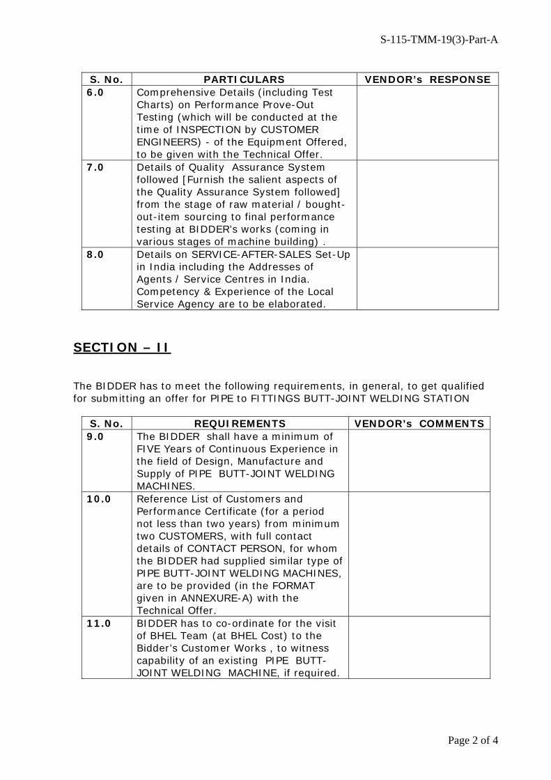
S. No. PARTICULARS VENDOR’s RESPONSE 6.0 Comprehensive Details (including Test
Charts) on Performance Prove-Out Testing (which will be conducted at the time of INSPECTION by CUSTOMER ENGINEERS) - of the Equipment Offered, to be given with the Technical Offer.
7.0 Details of Quality Assurance System followed [Furnish the salient aspects of the Quality Assurance System followed] from the stage of raw material / bought-out-item sourcing to final performance testing at BIDDER’s works (coming in various stages of machine building) .
8.0 Details on SERVICE-AFTER-SALES Set-Up in India including the Addresses of Agents / Service Centres in India. Competency & Experience of the Local Service Agency are to be elaborated.
SECTION – II The BIDDER has to meet the following requirements, in general, to get qualified for submitting an offer for PIPE to FITTINGS BUTT-JOINT WELDING STATION
S. No. REQUIREMENTS VENDOR’s COMMENTS 9.0 The BIDDER shall have a minimum of
FIVE Years of Continuous Experience in the field of Design, Manufacture and Supply of PIPE BUTT-JOINT WELDING MACHINES.
10.0 Reference List of Customers and Performance Certificate (for a period not less than two years) from minimum two CUSTOMERS, with full contact details of CONTACT PERSON, for whom the BIDDER had supplied similar type of PIPE BUTT-JOINT WELDING MACHINES, are to be provided (in the FORMAT given in ANNEXURE-A) with the Technical Offer.
11.0 BIDDER has to co-ordinate for the visit of BHEL Team (at BHEL Cost) to the Bidder’s Customer Works , to witness capability of an existing PIPE BUTT-JOINT WELDING MACHINE, if required.
S-115-TMM-19(3)-Part-A
Page 3 of 4
SECTION – III The BIDDER has to comply with the following, for accepting the Technical Offer for scrutiny by the Purchaser :
S.No. REQUIREMENTS VENDOR’s COMPLIANCE
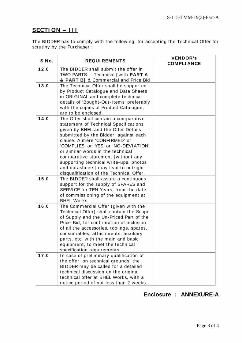
12.0 The BIDDER shall submit the offer in TWO PARTS - Technical [with PART A & PART B] & Commercial and Price Bid
13.0 The Technical Offer shall be supported by Product Catalogue and Data Sheets in ORIGINAL and complete technical details of ‘Bought-Out-Items’ preferably with the copies of Product Catalogue, are to be enclosed.
14.0 The Offer shall contain a comparative statement of Technical Specifications given by BHEL and the Offer Details submitted by the Bidder, against each clause. A mere ‘CONFIRMED’ or ‘COMPLIES’ or ‘YES’ or ‘NO-DEVIATION’ or similar words in the technical comparative statement [without any supporting technical write-ups, photos and datasheets] may lead to outright disqualification of the Technical Offer.
15.0 The BIDDER shall assure a continuous support for the supply of SPARES and SERVICE for TEN Years, from the date of commissioning of the equipment at BHEL Works.
16.0 The Commercial Offer (given with the Technical Offer) shall contain the Scope of Supply and the Un-Priced Part of the Price-Bid, for confirmation of inclusion of all the accessories, toolings, spares, consumables, attachments, auxiliary parts, etc. with the main and basic equipment, to meet the technical specification requirements.
17.0 In case of preliminary qualification of the offer, on technical grounds, the BIDDER may be called for a detailed technical discussion on the original technical offer at BHEL Works, with a notice period of not less than 2 weeks.
Enclosure : ANNEXURE-A

S-115-TMM-19(3)-Part-A
Page 4 of 4
ANNEXURE-A PERFORMANCE CERTIFICATE – [SAMPLE FORMAT]
(On Customer’s Letter Head with Additional Sheet – if necessary)
1. Supplier of the Equipment : 2. Make & Model of the Equipment : 3. Month & Year of Commissioning : 4. Application for which the Equipment is used : 5. a. Equipment Serial Number : b. Pipe Handling Capacity – Dia. Range & Weight : c. Power Rating of the Welding Powersoruce : d. Speed Control Mechanism & Other Features : e. List of Accessories procured with the Equipment : 6. Performance of the Equipment : Satisfactory / Good / Average / Not Satisfactory 7. Feed- back on ‘After Sales Service’ by the Supplier : 8. Remarks / Reasons for Recommendations to BHEL : Date: Signature & Seal of the Authority Issuing the Performance Certificate

S-115-TMM-19(3)-Part-B
Page 1 of 19
PART – B TECHNICAL SPECIFICATIONS FOR PIPE TO PIPE / PIPE TO FITTINGS BUTT WELDING STATION AA. JOB DESCRIPTION : The welding station is intended to do circumferential butt welding of steel pipes to steel pipes or steel pipes to fittings (like elbows & tees) using submerged arc welding process. The weld butt joint is formed by joining the free end of the pipes and fittings, which will have weld edge preparation to meet the welding requirements. The root of the butt joint is welded by GTAW (TIG Welding) process and followed by minimum two layers of SMAW (Manual Arc Welding) or GMAW (Flux Cored Arc Welding) process for build up and to hold the work-piece on self weight for further welding (by sub-merged arc welding process). The GTAW , SMAW and GMAW are not carried out in the proposed welding station and these are done separately at a different work station. BB. WELDING STATION CONFIGURATION : The welding station shall have the following two distinct components :- a. Job Manipulator It is the device which has to hold the work-piece and to rotate (with provision for
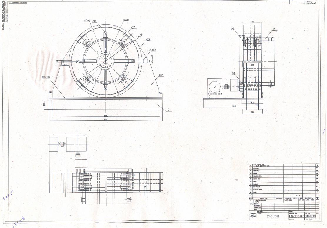
variable speed of rotation) the work-piece with circular profile for welding operation. The manipulator will have to consist of one drive unit for holding the work-piece and imparting the rotation and the other for job support at the free end. ANNEXURE–1 & 2 give only the indicative and schematic sketch for the manipulator and roller support units. The DIMENSIONS given in the DRAWINGS have to be IGNORED and the BIDDER can propose a better system design (provided it meets BHEL’s Shopfloor Practical Requirements).
b. Welding Machine It is the equipment which has to carry out the welding operation and shall consist of a
welding powersource, welding head and the (column & boom type) manipulator carrying the welding head and also helps to position the welding head with respect to the weld joint.
[BHEL will make provisions for baking of welding flux and recovery of unused flux from the welding zone]

S-115-TMM-19(3)-Part-B
Page 2 of 19
CC. DETAILED TECHNICAL SPECIFICATIONS
S.No. PARTICULARS AND BHEL SPECIFICATION BIDDER’S OFFER (with Technical Details)
1.0.0 PURPOSE & WORKPIECE MATERIAL 1.1.0 a. The butt welding station is required to clamp, rotate and weld
i. pipes fitted together ii. one or more fittings (Tees) fitted between pipe segments iii. elbows fitted to the end of pipe OR iv. a combination of above b. The header pipes, Tees and Elbows form high pressure components of
Power Boilers for Utilities & Industries, and Industrial boilers of Process Industries.
c. The components are to be clamped and Rotation is in the horizontal axis for performing cir-seam welding at the required welding speed.
d. The Tees & Elbows will have a radial over hang of maximum 500 mm and cause unbalance during rotation. Axial Over hang of the jobs will be maximum 5000 mm from the center of the clamp.
e. The jobs will be clamped in the job rotator/manipulator and the welding junction is subjected to preheating up to the temperature of 250 0 C before welding.
f. The welding may be done as close as 500 mm from the job rotator and hence the rotator components should be designed to withstand the heat radiation due to preheating.
1.2.0 WORKPIECE MATERIAL 1.2.1 A) CARBON STEEL: SA 106 Gr.B / Gr C (ASTM), AP15L Gr B (ASTM)
B) ALLOY STEEL: SA 335 P11, P12 & P22, P91, SA 312 TP304H, SA 312 TP316 L
1.3.0 MATERIAL SIZES 1.3.1 The equipment shall be suitable for handling the pipe with outer diameter ranging
from 219 mm to 1064 mm
1.3.2 The sizes of Pipes, Tees & Elbows are generally falling in the range of Industry Standards . The Maximum Length of the job is 15,000 mm
1.3.3 The weight of the single work-piece after the weld joints fit up (taken up for sub-merged arc welding) will not exceed 40,000 kgs. (40 Metric Tonnes)

S-115-TMM-19(3)-Part-B
Page 3 of 19
S.No. PARTICULARS AND BHEL SPECIFICATION BIDDER’S OFFER (with Technical Details)
2.0.0 CONFIGURATION 2.1.0 The Welding Station shall consist of
a. A Job Rotator/Manipulator with Supports b. Welding System including Column & Boom
Vendor to confirm.
2.2.0 JOB ROTATOR DETAILS 2.2.1 JOB Clamping System : 2.2.2 The system shall be suitable for centering and
clamping jobs mentioned in straight pipes, bends, Tees and Elbows in horizontal axis.
Vendor to confirm.
2.2.3 a. The Equipment shall have a hollow metallic housing mounted suitably on a rigid metallic base.
b. The base shall have suitable anchoring provisions for fixing the equipment with the shopfloor/ on earth or free standing type.
c. A hollow metallic ring of required thickness and ruggedness, with suitable job clamping arrangement shall be positioned concentric inside the above hollow housing.
d. The arrangement between the housing and the ring should permit the ring to rotate inside the housing smooth with out friction.
e. The housing shall have provision for adjusting the clearance between the housing and the ring for smooth and concentric rotation.
f. The job to be welded shall be held horizontally at the center, concentric with the hollow ring.
g. The Job clamping arrangement shall establish good contact area with the job to avoid slipping during rotation.
h. The job-clamping members shall be independently operated and manually.
i. The job clamping arrangement shall have gradua-tions in ‘mm’ on the sliding members to indicate the diameter of the job to be held inside for job setting
Vendor to confirm.
S-115-TMM-19(3)-Part-B
Page 4 of 19
S.No. PARTICULARS AND BHEL SPECIFICATION BIDDER’S OFFER (with Technical Details)
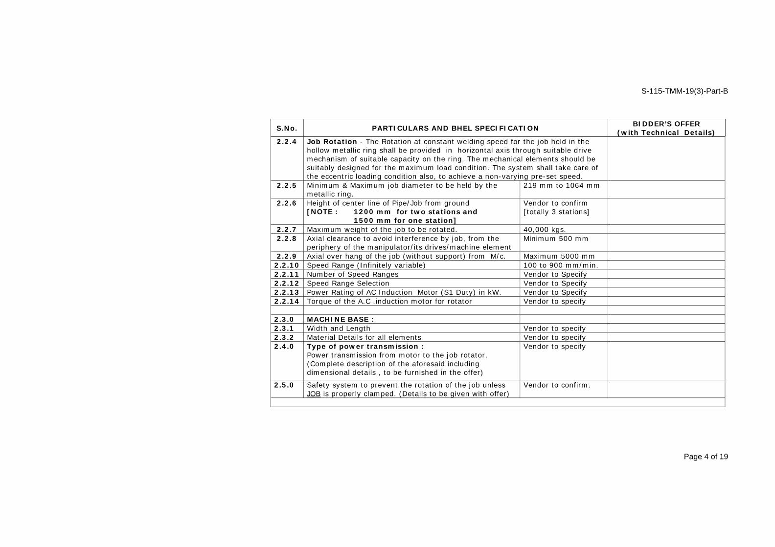
2.2.4 Job Rotation - The Rotation at constant welding speed for the job held in the hollow metallic ring shall be provided in horizontal axis through suitable drive mechanism of suitable capacity on the ring. The mechanical elements should be suitably designed for the maximum load condition. The system shall take care of the eccentric loading condition also, to achieve a non-varying pre-set speed.
2.2.5 Minimum & Maximum job diameter to be held by the metallic ring.
219 mm to 1064 mm
2.2.6 Height of center line of Pipe/Job from ground [NOTE : 1200 mm for two stations and 1500 mm for one station]
Vendor to confirm [totally 3 stations]
2.2.7 Maximum weight of the job to be rotated. 40,000 kgs. 2.2.8 Axial clearance to avoid interference by job, from the
periphery of the manipulator/its drives/machine element Minimum 500 mm
2.2.9 Axial over hang of the job (without support) from M/c. Maximum 5000 mm 2.2.10 Speed Range (Infinitely variable) 100 to 900 mm/min. 2.2.11 Number of Speed Ranges Vendor to Specify 2.2.12 Speed Range Selection Vendor to Specify 2.2.13 Power Rating of AC Induction Motor (S1 Duty) in kW. Vendor to Specify 2.2.14 Torque of the A.C .induction motor for rotator Vendor to specify
2.3.0 MACHINE BASE : 2.3.1 Width and Length Vendor to specify 2.3.2 Material Details for all elements Vendor to specify 2.4.0 Type of power transmission :
Power transmission from motor to the job rotator. (Complete description of the aforesaid including dimensional details , to be furnished in the offer)
Vendor to specify
2.5.0 Safety system to prevent the rotation of the job unless JOB is properly clamped. (Details to be given with offer)
Vendor to confirm.

S-115-TMM-19(3)-Part-B
Page 5 of 19
S.No. PARTICULARS AND BHEL SPECIFICATION BIDDER’S OFFER (with Technical Details)
2.6.0 OPERATION AND CONTROL SYSTEM - OPERATOR'S PANEL 2.6.1 a. One Panel on the equipment controller side and other with Remote Pendant
along with 15 mtr cable length, having complete machine control system with required configuration, shall be provided for convenient and efficient operation.
b. All switches shall be within reach of Operator. All displays / indications shall also be conveniently located (Schematic Layout with details to be submitted with the offer)
2.7.0 DRIVE SYSTEM & FEATURES 2.7.1 Make: Internationally Reputed makes only Vendor to specify 2.7.2 Type: AC Digital Variable Speed Drive [latest version] Vendor to specify 2.7.3 Model : Technically Suitable and Latest Version
(as available at the time of ordering, shall be supplied) Vendor to specify
2.7.4 Details of Standard Features Vendor to specify 2.7.5 Details of Optional Features, recommended by vendor. Vendor to specify 2.7.6 a. The drive for the equipment shall be of AC Motor
with Digital Controller. b. The Motor & Controller shall be of suitable capacity
(kW rating) to control the job rotating speed infinitely adjustable from minimum to maximum.
c. The controller should able to control the motor speed precisely rated for rotating 40,000 kgs weight job, including effect due to eccentric loading.
d. The controller shall able to be operated either from control panel or from remote station through hand held unit approximately 15 mtr cable distance.
e. Drive Controller Software is to be furnished. For Downloading / Up loading
Vendor to Confirm
S-115-TMM-19(3)-Part-B
Page 6 of 19
S.No. PARTICULARS AND BHEL SPECIFICATION BIDDER’S OFFER (with Technical Details)
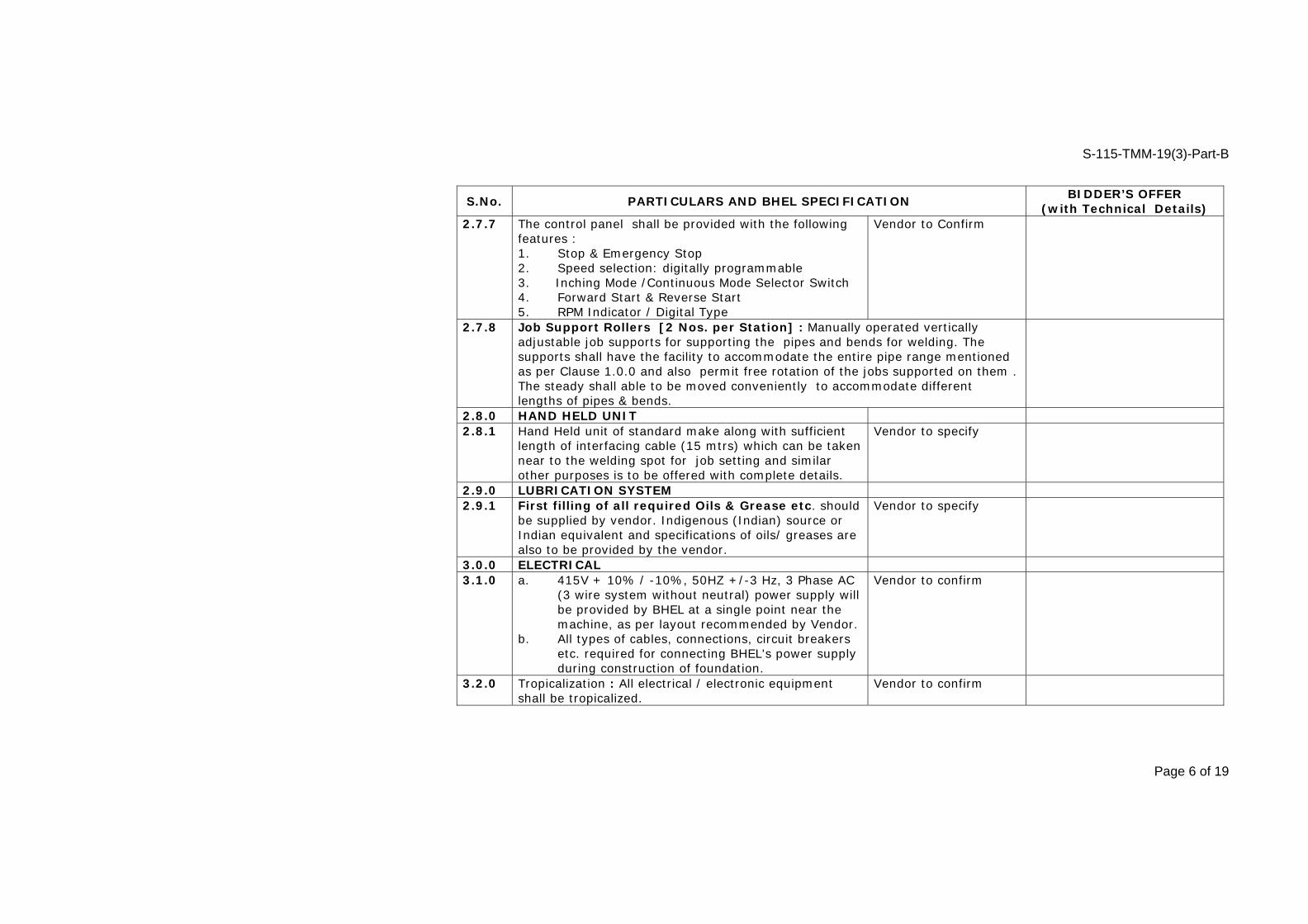
2.7.7 The control panel shall be provided with the following features : 1. Stop & Emergency Stop 2. Speed selection: digitally programmable 3. Inching Mode /Continuous Mode Selector Switch 4. Forward Start & Reverse Start 5. RPM Indicator / Digital Type
Vendor to Confirm
2.7.8 Job Support Rollers [2 Nos. per Station] : Manually operated vertically adjustable job supports for supporting the pipes and bends for welding. The supports shall have the facility to accommodate the entire pipe range mentioned as per Clause 1.0.0 and also permit free rotation of the jobs supported on them . The steady shall able to be moved conveniently to accommodate different lengths of pipes & bends.
2.8.0 HAND HELD UNIT 2.8.1 Hand Held unit of standard make along with sufficient
length of interfacing cable (15 mtrs) which can be taken near to the welding spot for job setting and similar other purposes is to be offered with complete details.
Vendor to specify
2.9.0 LUBRICATION SYSTEM 2.9.1 First filling of all required Oils & Grease etc. should
be supplied by vendor. Indigenous (Indian) source or Indian equivalent and specifications of oils/ greases are also to be provided by the vendor.
Vendor to specify
3.0.0 ELECTRICAL 3.1.0 a. 415V + 10% / -10%, 50HZ +/-3 Hz, 3 Phase AC
(3 wire system without neutral) power supply will be provided by BHEL at a single point near the machine, as per layout recommended by Vendor.
b. All types of cables, connections, circuit breakers etc. required for connecting BHEL's power supply during construction of foundation.
Vendor to confirm
3.2.0 Tropicalization : All electrical / electronic equipment shall be tropicalized.
Vendor to confirm

S-115-TMM-19(3)-Part-B
Page 7 of 19
S.No. PARTICULARS AND BHEL SPECIFICATION BIDDER’S OFFER (with Technical Details)
3.3.0 All electrical/electronic control cabinets & panels shall be dust & vermin proof and shall have IP 54 protection
Vendor to confirm
3.4.0 a. All electrical and electronic panels including operator's panel should be provided with fluorescent lamps for sufficient illumination and power receptacles of 220Volts, 5/15 Amp AC.
b. All adapters /receptacles should have compatibility with Indian equivalents.
Vendor to confirm
3.5.0 Motors & other electrical components shall conform to IEC or Indian Standards. Makes recommended are Siemens, ABB, Crompton Greaves, Kirloskar, etc.
Vendor to confirm
3.6.0 Vendor shall ensure the proper earthing for the machine and its peripherals.
Vendor to confirm
3.7.0 The Job Support Rollers shall be provided with Welding Return Current/Earth Ring Adaptor to close the circuit
4.0.0 SPARES FOR JOB MANIPULATOR 4.1.0 a. Itemized breakup of mechanical, hydraulic,
electrical and electronic spares used on the machine in sufficient quantity as per recommendation of Vendor for 2 years of trouble free operation on three shifts continuous running basis should be offered by vendor.
b. Unit Price for each item of spare shall be offered.
Vendor to confirm
5.0.0 BUTT-JOINT WELDING (Submerged Arc Welding ) MACHINE 5.1.0
Purpose The equipment is intended for circumferential welding materials as per the above cited Specification Clause 1.0.0, using mechanized job rotator.

S-115-TMM-19(3)-Part-B
Page 8 of 19
S.No. PARTICULARS AND BHEL SPECIFICATION BIDDER’S OFFER (with Technical Details)
5.2.0 EQUIPMENT CONFIGURATION 5.2.1
Machine Elements
The offered equipment shall consist of the following : a. Fully Thyristorised Welding Powersource b. Sub-Merged Arc Welding Head - with Torch Positioning Vice - mounted on Manipulator c. Control Panel for setting the Welding Parameters d. Set of Inter-Connecting Power, Earth & Control Cables
5.3.0 CONSTRUCTIONAL FEATURES 5.4.0 WELDING POWERSOURCE 5.4.1 Current Range 100 to 1000 Amps. 5.4.2 Duty Cycle Continuous – 100 % 5.4.3 O C V Minimum 65 V DC 5.4.4 Welding Voltage 20 to 50 Volts DC 5.4.5 Power Rating Bidder to specify the Power Rating (input) of the equipment 5.4.6 Characteristics Full Wave Constant Potential 5.4.7 Input Power
Supply 415 ±10% V, 50 ± Hz, 3-phase AC, 3 - wire system [4th Wire for PE/Earthing]
5.4.8 Insulation Class H 5.4.9 Design Feature Fully Thyristorised with six SCRs 5.4.10 Transformer
Windings
The transformer coils in the power and control transformers shall be of 100 % copper or superior quality aluminium windings (copper winding is preferable )
5.4.11 Parameter Reading Meters
Factory installed Ammeter & Voltmeter (either analogue or digital type) on front panel with easy removal and replacement from front-side for meter calibration purpose. Bidder to specify the make & size of meters.
5.4.12 Remote Control Unit
Hand-held remote control unit for welding current & voltage variation to be provided.
5.4.13 Output Terminal Terminals shall be of Bolt & Nut type with Nickel Coating 5.4.14
Protection Design to take care of protection (by tripping) due to electric short-circuit, single/two phase power input instead of three phase, thermal overload/overheating, etc.

S-115-TMM-19(3)-Part-B
Page 9 of 19
S.No. PARTICULARS AND BHEL SPECIFICATION BIDDER’S OFFER (with Technical Details)
5.4.15 Auxiliary Power
Two numbers of tapping sockets/plug points for connecting hand-lamps of rating 24 V/40W with MCBs for protection, to be provided
5.4.16
Cooling Fans
The powersource shall be ‘force air cooled’ with one/two fans of suitable rating, to withstand the continuous welding operation in the peak ambient conditions, especially in the tropical environment of 45 to 50 Deg. C.
5.4.17 Lifting Hook Two numbers of lifting hook to be provided at suitable locations, for handling by EOT Crane
5.4.18 Working Environment
The ambient conditions relate to a maximum value of 85% Humidity and 45 Deg. C Temperature (both maximum values do not occur simultaneously) in the Shopfloor.
5.4.19 Castor Wheels Four numbers of castor wheels of suitable size to be provided for easy mobility within shopfloor
5.5.0 WELDING HEAD 5.5.1
Wire Feed System
The welding head shall consist of wire feed mechanism incorporating a high torque DC geared motor, wire straightening and feed rollers, welding tip, vertical and horizontal adjustment mechanism
5.5.2 Head Adjustment in X-Y Axes
a. Vertical Traverse : Min. 250 mm b. Horizontal Traverse to weld seam : Min. 200 mm
5.5.3 Welding Head - Angular Displacement
a. Along the Vertical Axis : 360° b. Vertical Plane Traverse to Weld - Seam : 45° c. Vertical Plane Parallel to Weld - Seam : 45°
5.5.4 Torch Tip Positioning
The welding head has to be adjusted transversely and also vertically to bring the welding tip in correct position and swivel up to 45° for fillet seams in fillet position.
5.5.5 Spot Light A preferably 24 V Spot Light (with flexible support) to view the weldment to be provided
5.5.6 Flux Hopper
Capacity of Flux Container : 10 kgs. Open / Shut-Off Manual Control Valve and Flux Feed Tube to be provided.

S-115-TMM-19(3)-Part-B
Page 10 of 19
S.No. PARTICULARS AND BHEL SPECIFICATION BIDDER’S OFFER (with Technical Details)
5.6.0 MOTORISED MANIPULATOR FOR WELDING HEAD 5.6.1
Purpose
To position the welding head at suitable locations, so that the manipulator can be lifted by crane (or by moving on rails laid on the floor for a length of 10 mtrs.) and brought near the weld joint (job) to be welded
5.6.2 Construction
Preferred configuration is of Column & Boom Design and to house the welding powersource on the platform. Welding Head & Control Panel are to be mounted on boom
5.6.3 Vertical Travel 1500 mm 5.6.4 Horizontal Travel 2000 mm 5.6.5
Technical Features
Bidder to give a. Traverse speed for all movements b. Dimensional schematic drawing for the manipulator c. Details on drives for all axes
5.7.0 MOTORISED TRACTOR FOR WELDING HEAD – OPTIONAL ITEM 5.7.1
Purpose An additional device (other than the column & boom type manipulator) for carrying the welding head to suit specific job applications
5.7.2 Tractor Design
The tractor carriage shall be fabricated from steel sheets and provided with four wheels suitably insulated and for travelling on rails
5.7.3
Trolley Drive
The trolley is to be driven by a high torque DC geared motor with the help of chain and sprocket arrangement, giving power to the four wheels, thereby avoiding any slippage of the wheels
5.7.4 Trolley Balancing
The trolley has to support the cross/vertical beam fitted with welding head on one side and control box on the opposite side, which can be fixed on the top of the trolley.
5.7.5 Free Drive Clutch
A suitable clutch arrangement has to be provided for disengaging the geared motor for manual pushing. And also handles for pushing and pulling the system manually.

S-115-TMM-19(3)-Part-B
Page 11 of 19
S.No. PARTICULARS AND BHEL SPECIFICATION BIDDER’S OFFER (with Technical Details)
5.7.6
Traversing Rail
Rails made out of steel sections with suitable reinforcements, in segments of 2000 mm (in length) with suitable end couplers to build a welding track of length more around 10 mtrs.
5.8.0 CONTROL PANEL FOR WELDING POWER SOURCE 5.8.1 Current Range 100 to 1200 Amps. 5.8.2 Welding speed 200 mm to 1000 mm/min. 5.8.3 Wire feed speed 1.0 to 7.5 M/Min. 5.8.4 Wire diameter 2.0 mm to 6.3 mm 5.8.5 Welding Current 1200 amps. at maximum 5.8.6 Control Type The speed controls shall be thyristorised for traction, wire
feed movements.
5.8.7 Control Panel
The thyristor controller shall be suitable to operate on the input voltage of 42 Volts or 110 Volts with necessary power and control PCBs for wire feed and carriage speed controls.
5.8.8 Location
The control panel shall be mountable on the welding head and shall be swivel type to fix at a convenient position for easy reading of welding parameters.
5.8.9
Controls / Display
The control panel shall incorporate the following : a). Indicating Meters for reading welding current, voltage and carriage speed. b). Potentiometer for wire feed and carriage speed adjustment. c). Push buttons for upward and downward inching of the electrode wire. d). Switches for Start and Stop of welding. e). Forward, off and reverse movement of the carriage. f). Spot Light ON/OFF Switch g). Indication Lamp for Welding 'ON'

S-115-TMM-19(3)-Part-B
Page 12 of 19
S.No. PARTICULARS AND BHEL SPECIFICATION BIDDER’S OFFER (with Technical Details)
5.9.0 INTER-CONNECTING CABLES 5.9.1
Length The control cables, welding and earth cables connecting the powersource to the welding head/control panel shall have a length of five metres.
5.9.2 Protection Suitable sheathing to be provided for the cables for withstanding the rough use in shopfloor.
5.9.3 End-Connectors All the cables shall be provided with suitable end-connectors for easy fixing up.
5.10.0 CONSUMABLES & SPARES - (Refer to ANNEXURE – 3 for type & quantity). 5.10.1
Consumables
Consumables like contact tip/nozzles for 2.4 mm, 3.15 mm, 4.0 mm, 4.8 mm and 5.0 mm dia. wires shall be quoted separately. Feed and straightening rollers suitable for the above said dia wires also may be quoted.
5.10.2 Spares
Electrical and Mechanical spares for two years of trouble free operation shall be quoted. List to cover items listed in ANNEXURE - 3, enclosed.
6.0.0 LEVELING & ANCHORING SYSTEM 6.1.0 Complete anchoring system including foundation bolts,
anchoring materials, fixators, leveling shoes etc should be supplied
Vendor to Confirm

S-115-TMM-19(3)-Part-B
Page 13 of 19
S.No. PARTICULARS AND BHEL SPECIFICATION BIDDER’S OFFER (with Technical Details)
7.0.0 SAFETY ARRANGEMENTS 7.1.0 Following safety features in addition to other standard
safety features should be provided on the machine : a. The complete welding station should have
adequate and reliable safety interlocks / devices to avoid damage to the machine, work piece and the operator due to the malfunctioning or mistakes.
b. Machine functions should be continuously monitored and alarm / warning indications through lights/ alarm number with messages (on display and panels) should be available.
c. A detailed list of all alarms / indications provided on machine should be submitted by the Vendor.
d. All the drive transmission elements , cables etc. on the machine should be well supported and protected. These should not create any hindrance to machine operator's movement for effective use of machine.
e. All the rotating parts used on machine should be statically & dynamically balanced to avoid undue vibrations, Noise and suitably guarded.
f. Emergency Switches at suitable locations as per International Norms should be provided.
g. All lubricated parts like drive gears shall have provision for collecting / preventing the used Lubrication oil from spilling over on to the ground.
Vendor to confirm
S-115-TMM-19(3)-Part-B
Page 14 of 19
S.No. PARTICULARS AND BHEL SPECIFICATION BIDDER’S OFFER (with Technical Details)
8.0.0 ENVIRONMENTAL PERFORMANCE OF THE MACHINE 8.1.0 The Machine should confirm to following factors related
to environment: a. Maximum noise level shall be 85 dB(A) at normal
load condition, 1meter away from the machine with correction factor for back ground noise.
b. There shall not be any emissions from the machine except fumes of welding during welding operation.
c. If any safety / environmental protection enclosure is required it should be built in the machine by the vendor.
d. Paint of the machine should be oil / coolant resistant and should not peel off and mix up with coolant.
e. The machine shall be suitable for an ambient temperature of +50 ° C and relative humidity of 85 % respectively, but both do not occur simultaneously
Vendor to Confirm
9.0.0 TOOLS FOR ERECTION, OPERATION & MAINTENANCE 9.1.0 The Vendor shall bring special tools and equipment
required for erection of the machine. Necessary tools like Torque Wrench, Spanners, Keys, grease guns etc. for operation and maintenance of the machine shall be supplied. List of such tools shall be submitted with offer
Vendor to confirm
10.0.0 MACHINE SPARES 10.1.0 Vendor to confirm that complete list of spares for
equipments and accessories, along with item part no / specification / type / model, and name & address of the spare supplier shall be furnished along with documentation to be supplied with the machine
Vendor to confirm
S-115-TMM-19(3)-Part-B
Page 15 of 19
S.No. PARTICULARS AND BHEL SPECIFICATION BIDDER’S OFFER (with Technical Details)
10.2.0 All types of spares for total station and accessories should be available for at least ten years after supply of the equipment. If equipment / control is likely to become obsolete in this period, the vendor should inform BHEL sufficiently in advance and provide drawings of parts / details of spares & suppliers to enable BHEL to procure these in advance, if required
Vendor to confirm
10.3.0 Recommended set of spares for all attachments are to be offered with details.
Vendor to confirm
10.4.0 Electrical /Electronic Spares : All types of Relays, Contactors, Proximity Switches, Push Buttons, Indicating Lamps, Semiconductor Fuses, Special Fuses, Circuit Breakers, Main Power Switch, spares for Motors, Drives, Power Module & Control Cards for Main Drives etc.
Vendor to confirm
11.0.0 DOCUMENTATION: 11.1.0 Three sets of following documents (3 Hard copies,) in
English Language should be supplied along with the machine
Vendor to confirm
11.2.0 Operating Manuals of equipments Vendor to confirm 11.3.0 Programming Manuals if any for the station. Vendor to confirm 11.4.0 Detailed Maintenance manual of machine with all
drawings of machine assemblies/sub-assemblies/parts including Electrical / Pneumatic/ Hydraulic Circuit Diagrams. All Assembly/ Sub Assembly Drawings shall be supplied with the part list also
Vendor to confirm
11.5.0 Maintenance, Interface & Commissioning Manuals for speed drives.
Vendor to confirm
11.6.0 Manufacturing drawings for all supplied components like drive transmission elements.
Vendor to confirm
11.7.0 Catalogues, O&M Manuals of all bought out items including drawings, wherever applicable.
Vendor to confirm

S-115-TMM-19(3)-Part-B
Page 16 of 19
S.No. PARTICULARS AND BHEL SPECIFICATION BIDDER’S OFFER (with Technical Details)
11.8.0 Detailed specification of all rubber items and hydraulic/ lube fittings
Vendor to confirm
11.9.0 Operating Manuals, Maintenance Manuals & Catalogues for all supplied Accessories.
Vendor to confirm
11.10.0 The vendor shall submit complete Master List of parts used in the equipment.
Vendor to confirm
11.11.0 One additional set of all the above documentation in CD as the SOFT COPY
Vendor to confirm
12.0.0 ERECTION & COMMISSIONING 12.1.0 a. Vendor to take full responsibility for supervision of
the erection & commissioning, testing of the machine, carrying out welding of test pieces etc.
b. Service requirement like power and air shall be provided by BHEL at only one point to be indicated by Vendor in their foundation/layout drawings.
c. Other requirements like crane and helping personnel shall also be provided by BHEL.
Details of these requirements should be informed by Vendor in advance
12.2.0 Tools, Tackles, instruments and other necessary equipment required to carry out all above activities should be brought by the Vendor.
Vendor to confirm
12.3.0 Commissioning spares, required for commissioning of the machine within stipulated time, shall be brought by the Vendor on returnable basis.
Vendor to confirm
12.4.0 Portion, if any, of the equipment, accessories and other supplied items where paint has rubbed off or peeled during transit or erection should be repainted and merged with the original surrounding paint by the vendor. For this purpose, the Vendor should supply sufficient quantity of touch-up paint of various colours of paint used.
Vendor to confirm

S-115-TMM-19(3)-Part-B
Page 17 of 19
S.No. PARTICULARS AND BHEL SPECIFICATION BIDDER’S OFFER (with Technical Details)
12.5.0 Schedule of Erection and Commissioning shall be submitted with the offer.
Vendor to confirm
12.6.0 Charges, duration, terms & conditions for E&C should be furnished in detail separately by Vendor along with offer.
Vendor to confirm
13.0.0 AMBIENT CONDITIONS & THERMAL STABILITY 13.1.0 Weather conditions are tropical, Atmosphere may be dust
laden during some part of the year. The equipment shall be kept in the normal shop floor condition
Vendor to confirm
13.2.0 Thermal Stability of the complete equipment keeping in view specified Ambient Conditions and accuracy requirements of BHEL components and vendor should ensure trouble free operation of the equipment.
Vendor to confirm
13.3.0 The equipment , including attachments and accessories, should be suitable for 24 hrs. Continuous operation to its full capacity for 24 hour a day and 7 days a week throughout.
Vendor to Confirm
14.0.0 PROVE-OUT OF BHEL COMPONENTS: 14.1.0 The trouble free rotation of the job rotator and welding
at rated speed and maximum rated capacity along with Flux recovery operation for the straight & bend pipes, Tees & Elbows for sizes given by BHEL during the technical discussions / at the time of releasing the Purchase Order.
Vendor to confirm
14.2.0 Full load test to demonstrate the maximum power & specified speed range of the equipment and welding prove out as per specification.
Vendor to confirm
14.3.0 Demonstration of all features of the machine, control system & accessories
Vendor to confirm

S-115-TMM-19(3)-Part-B
Page 18 of 19
S.No. PARTICULARS AND BHEL SPECIFICATION BIDDER’S OFFER (with Technical Details)
15.0.0 MACHINE PROVE - OUT 15.1.0 Tests / Activities to be carried out at BHEL works while
commissioning the equipment:
15.2.0 Full load test to demonstrate the maximum power & specified speed range of the equipment, welding prove out, all operational features of the total welding station, as per specification.
Vendor to confirm
15.3.0 Demonstration of all features of the equipment, control system & accessories to the satisfaction of BHEL for efficient and effective use of the equipment
Vendor to confirm
15.4.0 Demonstration by actual use of all supplied attachments and accessories to their full capacity.
Vendor to confirm
15.5.0 Supervision by vendors of independent operation of each system of the equipment by BHEL after job prove out.
Vendor to confirm
16.0.0 MACHINE PACKING 16.1.0 Sea worthy & rigid packing for all items of complete
equipment System, all accessories and other supplied items to avoid any damage/loss in transit. When the equipment is dispatched in containers, all small loose items shall be suitably packed in boxes
Vendor to confirm
17.0.0 PERFORMANCE GUARANTEE 17.1.0 Performance Guarantee for a minimum period of TWELVE
months (for the machine in total and sub-systems or bought-out items in particular) from the date of acceptance of the machine, at BHEL Works.
Vendor to confirm
18.0.0 GENERAL POINTS 18.1.0 equipment Model No. Vendor to specify 18.2.0 Total connected load (kVA): Vendor to specify

S-115-TMM-19(3)-Part-B
Page 19 of 19
S.No. PARTICULARS AND BHEL SPECIFICATION BIDDER’S OFFER (with Technical Details)
18.3.0 Floor area required (Length, Width, Height) for complete equipment & accessories
Vendor to specify
18.4.0 Equipment lubrication Vendor to specify 18.5.0 Painting of Equipment / Electrical Panels using RAL 6011
Apple Green Colour (Polyurethane Paint) Vendor to confirm
18.6.0 All gears are to be hardened and ground Vendor to specify. 18.7.0 Total weight of the individual systems of equipment Vendor to specify 18.8.0 Weight of heaviest part of machine Vendor to specify 18.9.0 Weight of the heaviest assembly / sub-assembly of the
equipment Vendor to specify
18.10.0 Dimensions of largest part/ sub-assembly/ assembly of the Equipment
Vendor to specify
18.11.0 Vendor to submit, along with offer, reference list of customers where similar equipments have been supplied mentioning broad specifications of the supplied equipment i.e. Model, Load Carrying Capacity, Main Drive Rating, etc,
Vendor to confirm
18.12.0 Detailed catalogues, sketch/ photographs of the equipment and accessories/ attachments should be submitted with the offer.
Vendor to confirm
ENCLOSURES : ANNEXURE – 1 & 2 : Indicative Schematic Sketch for Manipulator Drive and Roller Support Units ANNEXURE – 3 : List of Spares for Sub-merged Arc Welding Machine


ANNEXURE - 3
LIST OF SPARES & CONSUMABLES
S.No. DESCRIPTION QTY. S.No. DESCRIPTION QTY. AA POWERSOURCE SPARES 1. O/P Terminal Board Assembly 1 No. 6. Receptacles – All Types 1 Sets in
each 2. I/P Terminal Board Assembly 1 No. 7. Cooling Fan Assembly 1 No. 3. All types of Printed Circuit Board (PCB) – with
part no and description 1 No in each.
8. Diodes –make and type no 2 no
4. Voltmeter 1 No 9. Indicator Lamps 10 Nos. 5. Ammeter 1 No. 10. SCR module -make and type no 3 Nos BB TRACTOR/WELDING HEAD /CONTROL PANEL SPARES 11. D.C. Motor with make and type no 1 No. 24. Contact Tip 5.00 mm 12 Nos. 12. Pressure Roller Assembly 1 No. 25. Wire Feed Nozzle (of Copper) 3 Nos. 13. Straightening Roller Assembly 1 No. 26. Switches 1 Set 14. Guide Roller Assembly 1 No. 27. Ammeter 1 No. 15. Tightening Knob Assembly 3 Nos. 28. Voltmeter 1 No. 16. Wire Guide House with Spiral 3 Nos. 29. Carriage Speed Motor with make
and type no 1 No.
17. Wire Guide Tube with Spiral 3 Nos. 30. Sockets – All Types 1 Set 18. Wirefeed Roll (3.15 mm dia. Wire) 3 Nos 31. Speed Control PCB Assembly 2 Nos. 19. Wirefeed Roll (4.00 mm dia. Wire) 6 Nos 32. Sequence Control PCB Assly 2 Nos. 20. Wirefeed Roll (4.80 mm dia. Wire) 6 Nos 33. Control Transformer with ratings 1 No. 21 Wirefeed Roll (5.00 mm dia. Wire) 6 Nos 34. Relays 1 set 22. Contact Tip 3.15 mm 6 Nos. 35. Main power supply PCB 1 No. 23. Contact Tip 4.00 mm 12 Nos. 36. Wire Spool Holder (25 kgs.) 3 Nos.