
Bhagwati Sponge Private Limitedenvironmentclearance.nic.in/writereaddata/Online/...BHAGWATI SPONGE...
41
at Project Proponent Bhagwati Sponge Private Limited 25, Ganesh Chandra Avenue, 4 th Floor, Kolkata-700 013 at Village Ikra, Jamuria, Jamuria Industrial Estate, District Burdwan, West Bengal
Transcript of Bhagwati Sponge Private Limitedenvironmentclearance.nic.in/writereaddata/Online/...BHAGWATI SPONGE...
at
Project Proponent
Bhagwati Sponge Private Limited25, Ganesh Chandra Avenue, 4th Floor, Kolkata-700 013
at Village Ikra, Jamuria, Jamuria Industrial Estate,
District Burdwan, West Bengal
BHAGWATI SPONGE PRIVATE LIMITED Pre-feasibility Report
1
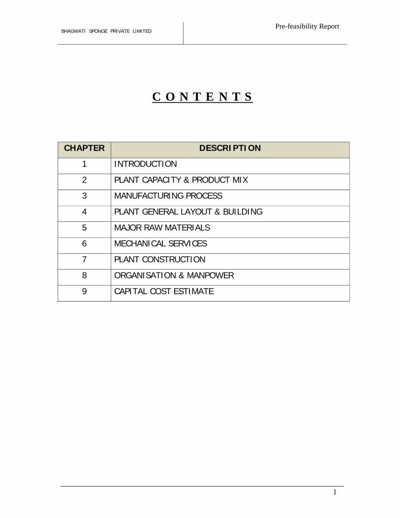
C O N T E N T S
CHAPTER DESCRIPTION
1 INTRODUCTION
2 PLANT CAPACITY & PRODUCT MIX
3 MANUFACTURING PROCESS
4 PLANT GENERAL LAYOUT & BUILDING
5 MAJOR RAW MATERIALS
6 MECHANICAL SERVICES
7 PLANT CONSTRUCTION
8 ORGANISATION & MANPOWER
9 CAPITAL COST ESTIMATE
BHAGWATI SPONGE PRIVATE LIMITED
1 -
1
1 – INTRODUCTION
Introduction
M/s. Bhagwati Sponge Private Limited (BSPL) is well known specially in the eastern India
for their manufacturing activities in steel sector. BSPL proposes to expand its existing Steel
Plant at village Ikra, Jamuria, Jamuria Industrial Estate, district Burdwan in West Bengal.
Considering the future growth potential of steel market at domestic and international level,
BSPL has decided to expand the existing steel plant by installation of Sponge Iron Plant,
SMS, Rolling Mill, Ferro-alloy plant & Captive Power Plant in the notified Industrial Area.
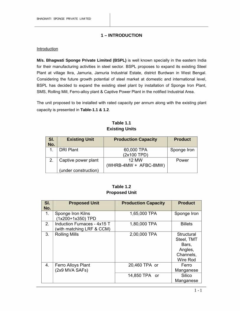
The unit proposed to be installed with rated capacity per annum along with the existing plant
capacity is presented in Table-1.1 & 1.2.
Table 1.1Existing Units
Table 1.2Proposed Unit
Sl. No.
Existing Unit Production Capacity Product
1. DRI Plant 60,000 TPA (2x100 TPD)
Sponge Iron
2. Captive power plant
(under construction)
12 MW(WHRB-4MW + AFBC-8MW)
Power
Sl. No.
Proposed Unit Production Capacity Product
1. Sponge Iron Kilns (1x200+1x350) TPD
1,65,000 TPA Sponge Iron
2. Induction Furnaces - 4x15 T(with matching LRF & CCM)
1,80,000 TPA Billets
3. Rolling Mills 2,00,000 TPA Structural Steel, TMT
Bars, Angles,
Channels, Wire Rod
4. Ferro Alloys Plant(2x9 MVA SAFs)
20,460 TPA or Ferro Manganese
14,850 TPA or Silico Manganese
BHAGWATI SPONGE PRIVATE LIMITED
1 -
2
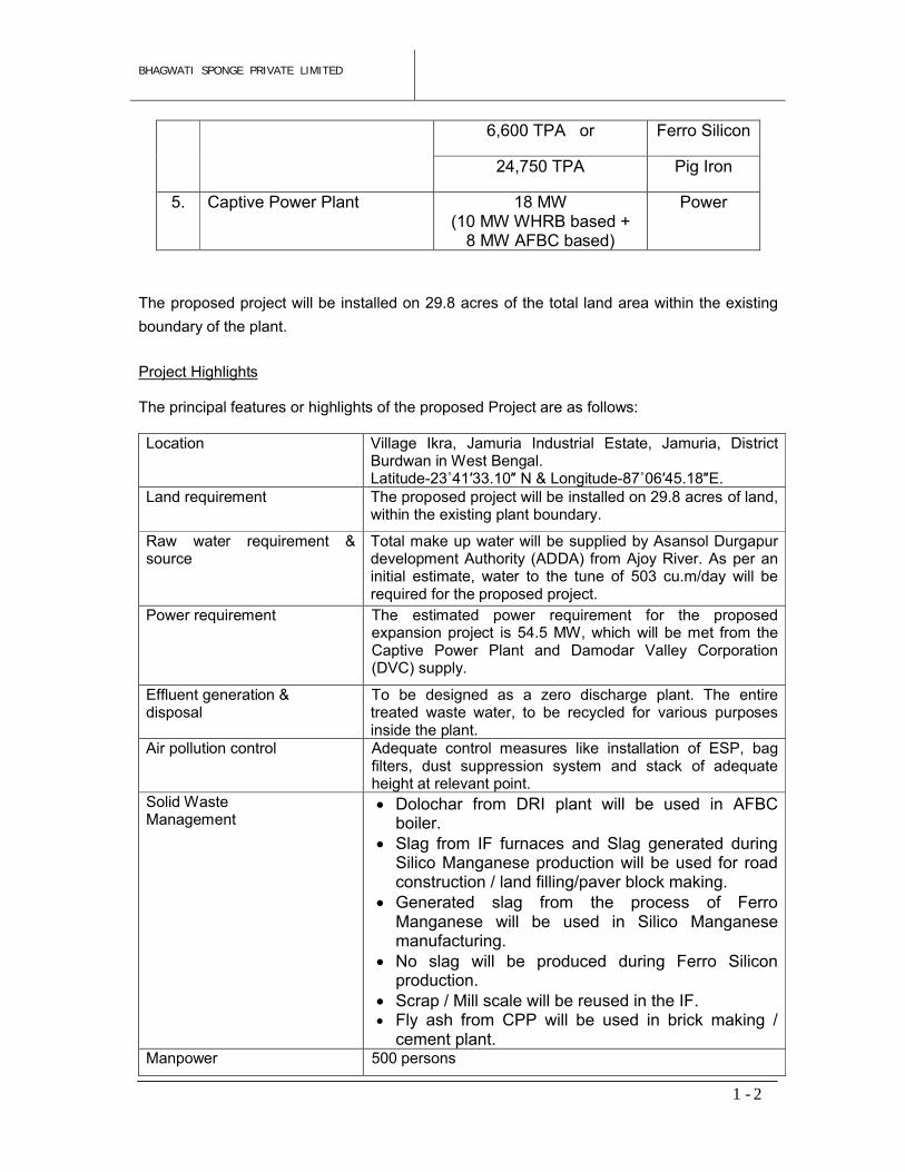
The proposed project will be installed on 29.8 acres of the total land area within the existing
boundary of the plant.
Project Highlights
The principal features or highlights of the proposed Project are as follows:
Location Village Ikra, Jamuria Industrial Estate, Jamuria, District Burdwan in West Bengal. Latitude-23˚41′33.10″ N & Longitude-87˚06′45.18″E.
Land requirement The proposed project will be installed on 29.8 acres of land, within the existing plant boundary.
Raw water requirement & source
Total make up water will be supplied by Asansol Durgapur development Authority (ADDA) from Ajoy River. As per an initial estimate, water to the tune of 503 cu.m/day will be required for the proposed project.
Power requirement The estimated power requirement for the proposed expansion project is 54.5 MW, which will be met from the Captive Power Plant and Damodar Valley Corporation (DVC) supply.
Effluent generation & disposal
To be designed as a zero discharge plant. The entire treated waste water, to be recycled for various purposes inside the plant.
Air pollution control Adequate control measures like installation of ESP, bag filters, dust suppression system and stack of adequate height at relevant point.
Solid Waste Management
Dolochar from DRI plant will be used in AFBC boiler.
Slag from IF furnaces and Slag generated during Silico Manganese production will be used for road construction / land filling/paver block making.
Generated slag from the process of Ferro Manganese will be used in Silico Manganese manufacturing.
No slag will be produced during Ferro Silicon production.
Scrap / Mill scale will be reused in the IF. Fly ash from CPP will be used in brick making /
cement plant.Manpower 500 persons
6,600 TPA or Ferro Silicon
24,750 TPA Pig Iron
5. Captive Power Plant 18 MW(10 MW WHRB based +
8 MW AFBC based)
Power
BHAGWATI SPONGE PRIVATE LIMITED
1 -
3
Project cost Rs. 324 Crores
Location of Project Site
The project site is located in the Jamuria Industrial Estate, Jamuria, district Bardhaman, West Bengal. Its graphical coordinates are Latitude 23˚41′33.10″ N & Longitude 87˚06′45.18″E. The Jamuria Industrial Estate Authorities, is a joint venture of Jamuria Municipality and the Asansol Durgapur Development Authority in Burdwan District of West Bengal.
The proposed site area is well developed and has all necessary infrastructure facilities such as motorable road upto the plant site, nearness to rail head, telephone telefax facilities etc.The proposed site is located on the State Highway at a distance of 5 km from the Durgapur Expressway (NH-2). Nearest railway station is Ikra which is around 1.0 km from the project site. NSCBI Airport, Kolkata is about 180 km in south-east direction from project site. Denselypopulated town Asansol is about 14.0 km in west direction from the project site. District Head Quarters Burdwan is about 92 km in south-east direction from the project site. The project site has good connectivity with sea port of Kolkata and Haldia.
Location of the project site is presented in Figure 1.1.
Need for the Project
National The development of industrial projects plays a key role in the economic growth of any country. Iron is perhaps the most important metal to the mankind and its principal alloy, steel, is widely used for domestic, agricultural, industrial and defense purposes. Per capita steel consumption is a major indicator of economic status of any country.
The Indian steel industry is poised for faster growth in the decades ahead as the industrial and economic development of the country gains pace. The steel industry has recorded remarkable performance in recent years. The industry is now capable of producing high quality materials of stringent international specification for high-end applications. The 21st century is widely perceived to be the century of Asia and India is looked upon as one of the economies with most promising prospects. This is a formidable challenge as well as an opportunity to the Indian corporate sector.
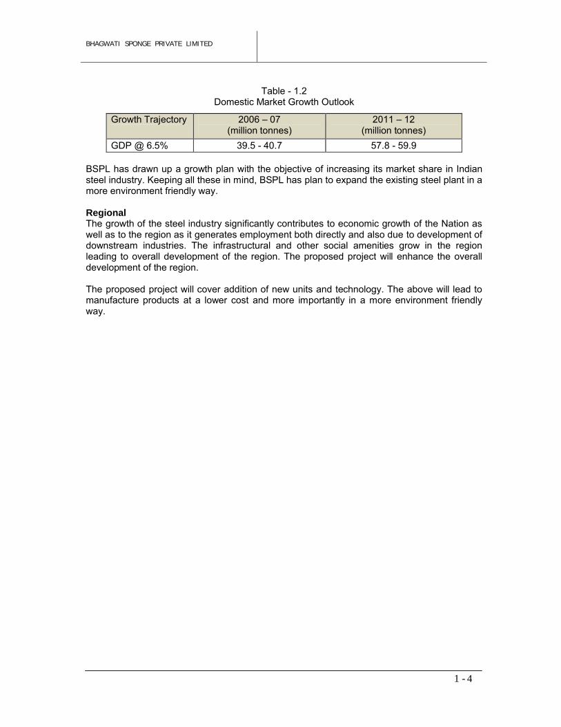
The estimated domestic market growth outlook for finished steel is given in Table - 1.2. The total steel consumption of finished steel has been estimated to touch 60 MT in the year 2012 from the current level of over 31 MT. Even after approximately doubling the production capacity the per capita domestic consumption would continue to be substantially below the world average of 145 Kg. There is good prospect of domestic steel consumption growing at about 6-7% up to the year 2012. The national steel policy has set a target of 60 million tonne of steel production by 2010 and to increase it to a level of 100 million tonne by 2018. BSPL is in position to fulfill its role in the nation’s quest for higher growth and development in the new millennium.
BHAGWATI SPONGE PRIVATE LIMITED
1 -
4
Table - 1.2Domestic Market Growth Outlook
Growth Trajectory 2006 – 07(million tonnes)
2011 – 12(million tonnes)
GDP @ 6.5% 39.5 - 40.7 57.8 - 59.9
BSPL has drawn up a growth plan with the objective of increasing its market share in Indian steel industry. Keeping all these in mind, BSPL has plan to expand the existing steel plant in a more environment friendly way.
Regional The growth of the steel industry significantly contributes to economic growth of the Nation as well as to the region as it generates employment both directly and also due to development of downstream industries. The infrastructural and other social amenities grow in the region leading to overall development of the region. The proposed project will enhance the overall development of the region.
The proposed project will cover addition of new units and technology. The above will lead to manufacture products at a lower cost and more importantly in a more environment friendly way.
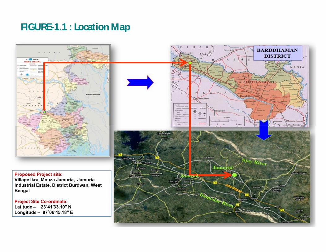
FIGURE-1.1 : Location Map
Proposed Project site:Village Ikra, Mouza Jamuria, Jamuria Industrial Estate, District Burdwan, West Bengal
Project Site Co-ordinate: Latitude – 23˚41′33.10″ NLongitude – 87˚06′45.18″ E
BHAGWATI SPONGE PRIVATE LIMITED
2 -
1
2 – PLANT CAPACITY & PRODUCT MIX
General
M/s. Bhagwati Sponge Iron Pvt. Ltd., is planning to install the proposed units at its existing
Steel Plant at Jamuria Industrial Estate, district Burdwan in West Bengal. There being a large
number of integrated steel plants in and around the industrial belt of Durgapur and a mush
room growth of tiny mini steel plants in this area producing alloy steel & carbon steel, the
promoters do not envisage any bottleneck in marketing their products locally. However, the
ferro-alloys have a strong international demand and export potentialities are also extremely
good.
Product-Mix
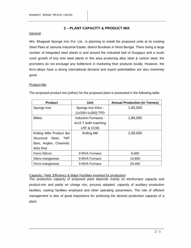
The proposed product-mix (either) for the proposed plant is presented in the following table.
Product Unit Annual Production (in Tonnes)
Sponge Iron Sponge Iron Kilns -
(1x200+1x350) TPD
1,65,000
Billets Induction Furnaces -
4x15 T (with matching
LRF & CCM)
1,80,000
Rolling Mills Product like
Structural Steel, TMT
Bars, Angles, Channels,
Wire Rod
Rolling Mill 2,00,000
Ferro-Silicon 9 MVA Furnace 6,600
Silico-manganese 9 MVA Furnace 14,850
Ferro-manganese 9 MVA Furnace 20,460
Capacity, Yield, Efficiency & Major Facilities involved for production The production capacity of proposed plant depends mainly on kiln/furnace capacity and
product-mix and partly on charge mix, process adopted, capacity of auxiliary production
facilities, casting facilities employed and other operating parameters. The role of efficient
management is also of great importance for achieving the desired production capacity of a
plant.
BHAGWATI SPONGE PRIVATE LIMITED
3 -
1
3 – MANUFACTURING PROCESS
3.1 MANUFACTURING PROCESS
3.1.1 SPONGE IRON PLANT
M/s BSPL is now operating 2 DRI kilns, each of 100 TPD capacity for production
of 60,000 TPA sponge iron. The company is now planning to install (1x200
+1x350) TPD DRI Kilns for production of 1,65,000 TPA Sponge Iron. So, the final
will be 2,25,000 TPA Sponge Iron.
Manufacturing ProcessThe plant uses the coal based process in which pellet is reduced with non-coking
type imported coal in a rotary kiln to make sponge iron.
The project activity involves installation of charge pre-heaters to utilise the waste
heat energy content of flue gases released during manufacturing process of the
sponge iron in rotary kilns. The charge pre-heaters will utilise the sensible heat
content of flue gases released at 950°C from the individual kilns to preheat the
incoming raw material i.e. pellet and dolomite mixture to around 900°C from
ambient temperature of 40°C. The charge pre-heaters are of miniature rotary kiln
design to enable adequate mixing of flue gases and raw material mixture for
effective heat transfer. Thereafter, the flue gases are released into the
atmosphere, complying with the environmental norms. The preheated raw material
is then fed to the main rotary kiln for further heating and reduction process to
produce sponge iron and hence reduces coal consumption for the same quantity of
production. In absence of such project activity, equivalent amount of coal would
have been consumed in the main rotary kiln to raise the temperature of the raw
material mixture to 900°C. The project activity thus helps in reduction of coal
consumption per tonne of sponge iron produced in the sponge iron kilns, thus
leading to green house gas (GHG) emission reductions.
The raw materials (Pellet, Imported coal and dolomite), in desired quantities and
sizes, are fed into the rotary kiln. The rotary kiln is a refractory lined cylindrical
vessel on which blowers and air pipes are mounted to provide combustion air to
the kiln. The rotary kiln has a downward slope and is mounted on rollers to enable
rotation. The angle of inclination, rotational speed, and length of time the charge is
exposed to the atmosphere and temperature has important bearings on the quality
of the end product. The rotary kiln has three functions as: It is a heat exchanger,
Vessel for chemical reaction, Conveyor for solids.
BHAGWATI SPONGE PRIVATE LIMITED
3 -
2
With the rotation of the kiln, the charge moves down the slope and the surface of
the material is exposed to heat. The heat exchange takes place via the non-
refractory lining of the kiln. The reduction from oxide to metal occurs by gradual
removal of oxygen at various temperatures giving rise to various intermediate
oxides. Hot sponge iron is discharged from the kiln- discharge end and taken into
the rotary cooler. The effluent gas that contains coal volatile, fine carbon particles
and sponge iron dust is treated separately in the waste gas handling system. The
system consists of:
(a) Dust settling chamber(b) After burner chamber(c) Waste heat recovery boiler(d) Electrostatic precipitator(e) ID fan(f) Chimney
Direct Reduced Iron / Sponge Iron Process (DRI)The process of reduction takes place inside the rotary kiln, which is mounted on 2 tyres and supported by 4 support rollers. The transverse motion of the kiln is controlled with the help of hydro thruster and thrust rollers. The kiln is rotated at the rate of 0.35 rpm with the help of a girth gear mounted on the kiln and connected with 1 pinion drives, which in turn are coupled with gear boxes and motors.
The direct reduction of iron ore inside the kiln is held due to CO gas, which is
generated out of coal at nearly 950°C. Shell air fans are mounted on the kiln,
which inject air in controlled manner into the kiln for creating reducing
atmosphere. The CO reacts with Fe2O3 and reduces it to Fe. The kiln is lined
with refractory for sustaining the high temperature.
The hot DRI is then cooled by indirect cooling inside a cooler. The rotary cooler
is supported on 2 tyres and 4 support rollers. The cooler is rotated at the rate of
0.6 rpm with the help of a girth gear mounted on the cooler and connected with
single pinion drive, which is coupled with a gearbox and motor. The water is
sprayed on the cooler shell while the sponge iron travels inside the cooler and
hence, the material gets cooled at outlet to 150°C while discharged on the
product conveyor.
Product SeparationThe sponge iron along with un-burnt coal in the form of char comes out of the
cooler. The sponge iron being magnetic is separated out of the char by
BHAGWATI SPONGE PRIVATE LIMITED
3 -
3
passing it through a magnetic separator. The sponge iron and char, recovered
separately, are stored in the storage bunkers and discharged through trucks.
Off gas cleaning systemThe off gases moving in counter current of material flow inside the kiln are at a
temperature of 1000°C and carry coal dust, which is passed through dust
settling chamber and after burning chamber (ABC). Air is added into the ABC
for converting CO to CO2. The hot flue gas stream is taken to the waste heat
recovery boiler for utilization of the sensible heat for making steam. The off
gases are then allowed to pass through ESP for removal of dust so that the
concentration of dust is limited to below 50 mg/Nm3 before being discharged
from the chimney.
In-plant de-dusting systemReverse air bag filter shall be installed for catching the dust from various
conveyors, material handling equipments and-product handling equipment. The
dust collected from the bag filter shall be conveyed pneumatically to a distant
location and discharged on trucks in wet condition.
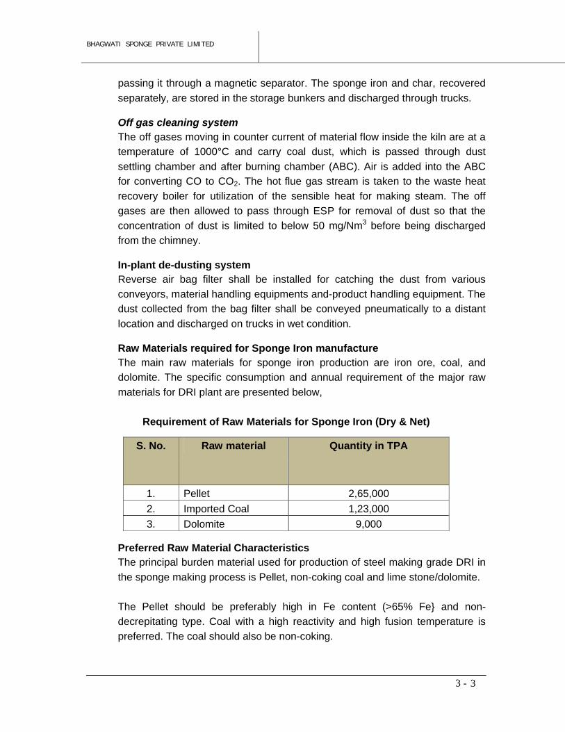
Raw Materials required for Sponge Iron manufactureThe main raw materials for sponge iron production are iron ore, coal, and
dolomite. The specific consumption and annual requirement of the major raw
materials for DRI plant are presented below,
Requirement of Raw Materials for Sponge Iron (Dry & Net)
Preferred Raw Material CharacteristicsThe principal burden material used for production of steel making grade DRI in
the sponge making process is Pellet, non-coking coal and lime stone/dolomite.
The Pellet should be preferably high in Fe content (>65% Fe} and non-
decrepitating type. Coal with a high reactivity and high fusion temperature is
preferred. The coal should also be non-coking.
S. No. Raw material Quantity in TPA
1. Pellet 2,65,000
2. Imported Coal 1,23,000
3. Dolomite 9,000
BHAGWATI SPONGE PRIVATE LIMITED
3 -
4
A low ash fusion temperature is undesirable as it promotes formation of
accretions in the kiln. The coal ash composition is also important as a siliceous
ash might react with ferrous oxide to form low melting ferrous silicate and
interfere with the reduction to metallic iron.
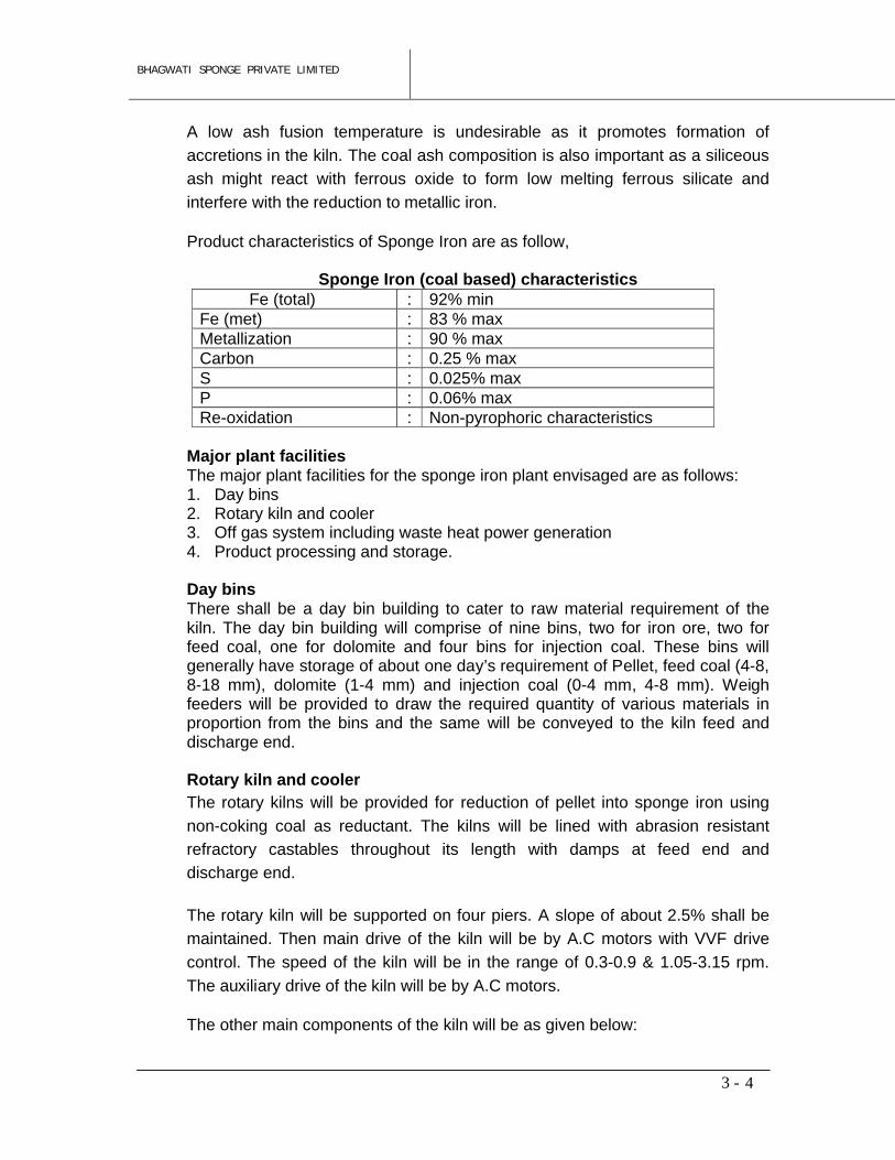
Product characteristics of Sponge Iron are as follow,
Sponge Iron (coal based) characteristicsFe (total) : 92% min
Fe (met) : 83 % maxMetallization : 90 % maxCarbon : 0.25 % maxS : 0.025% maxP : 0.06% maxRe-oxidation : Non-pyrophoric characteristics
Major plant facilitiesThe major plant facilities for the sponge iron plant envisaged are as follows:1. Day bins2. Rotary kiln and cooler3. Off gas system including waste heat power generation4. Product processing and storage.
Day binsThere shall be a day bin building to cater to raw material requirement of the kiln. The day bin building will comprise of nine bins, two for iron ore, two for feed coal, one for dolomite and four bins for injection coal. These bins will generally have storage of about one day’s requirement of Pellet, feed coal (4-8, 8-18 mm), dolomite (1-4 mm) and injection coal (0-4 mm, 4-8 mm). Weigh feeders will be provided to draw the required quantity of various materials in proportion from the bins and the same will be conveyed to the kiln feed and discharge end.
Rotary kiln and coolerThe rotary kilns will be provided for reduction of pellet into sponge iron using
non-coking coal as reductant. The kilns will be lined with abrasion resistant
refractory castables throughout its length with damps at feed end and
discharge end.
The rotary kiln will be supported on four piers. A slope of about 2.5% shall be
maintained. Then main drive of the kiln will be by A.C motors with VVF drive
control. The speed of the kiln will be in the range of 0.3-0.9 & 1.05-3.15 rpm.
The auxiliary drive of the kiln will be by A.C motors.
The other main components of the kiln will be as given below:
BHAGWATI SPONGE PRIVATE LIMITED
3 -
5
a. Feed end and discharge end transition housing of welded steel construction with refractory lining including feed chute.
b. Pneumatic cylinder actuated labyrinth air seal complete with auto lubricating at feed end and discharge end.
c. On board equipments like fans, manifolds, ports, slip ring, instrumentation etc.
d. Cooling fans at feed end and discharge end.e. Feed end double pendulum valve & dust valves.
In the pre-heater & kiln, the pellet will be heated to the reduction temperature of 1000-1050°C. The pellet will be reduced to metallic iron by carbon dioxide generated in the kiln from coal. The heat required for the reduction process will also be supplied by the combustion of coal.
Thermocouple will be installed along the length of the kiln shell for measurement of thermal profile of the kiln. The temperature will be controlled by regulating the amount of combustion air admitted into the kiln through no. of ports with help of fans mounted on the kiln will have variable speed drive.Auxiliary drive is provided for slow rotation.
The reduced material from the kiln will be cooled indirectly in a rotary cooler by an external water spray. The kiln will be provided with one rotary cooler. The rotary cooler will be of 2.3 m & 8.0 m dia. and 22 m & 77 m length and will be supported on two piers with a slope of about 2.5%. The main drive and the auxiliary drive of the cooler will be by separate AC motor. The speed of the drive will be about 0.3-0.9 & 1.05-3.15 rpm. The cooler will be provided with one plain riding ring and thrust riding ring and will be provided with four sets of support rollers at two piers and one set of hydraulic thrust rollers with antifriction bearings. About 1 m end portion of the cooler acts as a screening section, which separates all the accretions larger than 50 mm from the reduced material. These lumps will be discharged separately via lump gate. Rest of the material will be discharged on to the conveyor via double pendulum valve.
The other main components of the cooler will be the following:
a. Feed end housing (part of reactor to cooler transition) of welded steel construction with refractory lining.
b. Cooler discharge end housing of welded steel construction.c. Pneumatic cylinder acuted labyrinth air seal complete with auto lubricating
system at feed and discharge end.
The cooler will be lined with refractory castable for about 4.0 m from the feed end. Bypass arrangement will be provided at discharge end of the cooler for emergency discharge of materials. The cooled product will be conveyed to the product processing building by a system of belt conveyors.
The cooling water will be collected in the trough below the cooler and sent to the cooling tower for cooling. The cooled water will be re-circulated. Closed circuit cooling system will be followed in the plant.
BHAGWATI SPONGE PRIVATE LIMITED
3 -
6
The rotary parts of the kiln and cooler will be sealed suitably against the stationary parts at the connecting points to avoid leakage of duct laden gas.
Product processing and storageThere shall be one product processing unit for handling the cooler discharge. The product containing sponge iron, char and spent lime from the cooler discharge end will be discharged to a set of conveyors and sent to the product processing building. The kiln cooler system shall have a separate surge bin. Product from surge bin can be withdrawn through vibrating feeder and to the product will first be screened in a double deck screen having 3mm and 20 mm screens. +20 materials shall be dumped as rejects. The screened product i.e. +3 – 20 mm and -3 mm fraction shall separately be sent to the product storage separation. Sponge iron lump (3-20) shall be sent to the product storage building for storing in two no. of bunkers where three days storage has been proposed. The sponge ion fines (-3 mm) will be stored in the fines bunker in the product processing building itself where one day storage will be provided. The sponge iron lump and fines will be further conveyed from the respective bunkers by truck to the steel making unit as per the requirement. The char/non-magnetic shall be stored in a separate bin from where it will be sent to the power plant through conveyors for its utilization for power generation in FBC boiler.
3.1.2 INDUCTION FURNACEM/s BSPL is now planning to install 4x15 T Induction Furnace in the existing plant area for production of 1,80,000 TPA Billets.
The manufacturing process for Steel Billets through Induction Furnace –Continuous Casting Machine is discussed below:
Ingot / Billets Making by Induction Furnace: The greatest advantage of the
induction furnace is its low capital cost compared with other types of melting
units. Its installation is relatively easier and its operation simpler. Among other
advantages, there is very little heat loss due to radiation from the furnace as
the path is constantly covered, and there is no noise attending its operation.
The molten metal in an induction furnace is circulated automatically by electro-
magnetic action so that when alloy additions are made, a homogenous product
is ensured in minimum time. While making Alloy or carbon steel in an electric
induction furnace, the foremost consideration is the optimum utilization of the
furnace as well as elimination of delays. The time between tap and charge, the
charging time, power delays, etc. are items of the utmost importance in meeting
the objective of maximum output in tones/hour at a low operational cost.
The Charge for Induction Furnace: Sponge iron and Scrap constitute the major
raw material for steelmaking in the induction furnace where selected scrap of
consistent quality, preferably the same as that of the steel to be produced, is
mainly used. This is because elimination of some elements from the molten
BHAGWATI SPONGE PRIVATE LIMITED
3 -
7
metal is difficult in an induction furnace melting, and in the cases where these
are present in high quantities; dilution is the only possible solution. That is why
procurement of the appropriate kind of Sponge iron and scrap is of utmost
importance in induction furnace melting practice.
The charge should be compact and should consist of a number of small pieces
of solid selected steel scrap mixed with sponge iron, clean turnings, borings or
other light scrap and a moderate amount of larger pieces. This is to provide the
initial conditions of a high-flux path through the charge for facilitating generation
of heat and commencement of melting. The charge is collected in skips on the
working platform and is charged into the furnace through the top opening by
removing the top lid of the furnace and tripping the skips. If the charge consists
of pieces of scrap varying size, the larger pieces are entered first and the
smaller pieces are packed about them as closely as possible. Even with the
closet packing it is necessary to gradually add the remaining charge as the
melting progresses. As soon as the furnace is charged, the switches admitting
ternating current to the induction coil are closed.
BHAGWATI SPONGE PRIVATE LIMITED
3 -
8
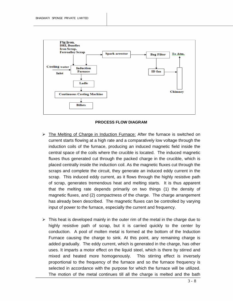
PROCESS FLOW DIAGRAM
The Melting of Charge in Induction Furnace: After the furnace is switched on
current starts flowing at a high rate and a comparatively low voltage through the
induction coils of the furnace, producing an induced magnetic field inside the
central space of the coils where the crucible is located. The induced magnetic
fluxes thus generated cut through the packed charge in the crucible, which is
placed centrally inside the induction coil. As the magnetic fluxes cut through the
scraps and complete the circuit, they generate an induced eddy current in the
scrap. This induced eddy current, as it flows through the highly resistive path
of scrap, generates tremendous heat and melting starts. It is thus apparent
that the melting rate depends primarily on two things (1) the density of
magnetic fluxes, and (2) compactness of the charge. The charge arrangement
has already been described. The magnetic fluxes can be controlled by varying
input of power to the furnace, especially the current and frequency.
This heat is developed mainly in the outer rim of the metal in the charge due to
highly resistive path of scrap, but it is carried quickly to the center by
conduction. A pool of molten metal is formed at the bottom of the Induction
Furnace causing the charge to sink. At this point, any remaining charge is
added gradually. The eddy current, which is generated in the charge, has other
uses. It imparts a motor effect on the liquid steel, which is there by stirred and
mixed and heated more homogenously. This stirring effect is inversely
proportional to the frequency of the furnace and so the furnace frequency is
selected in accordance with the purpose for which the furnace will be utilized.
The motion of the metal continues till all the charge is melted and the bath

BHAGWATI SPONGE PRIVATE LIMITED
3 -
9
develops a convex surface. However, as the convex surface is not favourable
to slag treatment, the power input is then naturally decreased to flatten the
convexity and to reduce the circulation rate when refining under a reducing
slag. The reduced flow of the liquid metal accelerates the purification reactions
by constantly bringing new metal into close contact with the slag. Before the
actual reduction of steel is done, the liquid steel, which might contain some
trapped oxygen, is first treated with some suitable de-oxidiser. When no
purification is attempted, the chief metallurgical advantages of the process
attributable to the stirring action are uniformity of the product, control over the
super-heat temperature, and the opportunity afforded by the conditions of the
melt to control de-oxidation through proper additions.
As soon as the charge has melted clear and de-oxidising actions have ceased,
any objectionable slag is skimmed off, and the necessary alloying elements are
added, when these activities have melted and then been diffused through the
bath, the power input may be increased to bring the temperature of metal up to
the point most desirable for pouring. The current then is turned off and the
furnace is tilted for pouring into a ladle. As soon as pouring has ceased, any
slag adhering to the wall of the crucible is scraped out and the furnace is
righted for charging again. As the furnace is equipped with a tight cover over
the crucible very little oxidation occurs during melting. Such a cover also
serves to prevent cooling by radiation from the surface of the molten metal.
Hence the use of slag covering for preventing heat loss and protecting the
metal is unnecessary, though slags are used in special cases. Another
advantage of the Induction furnace is that there is hardly any melting loss
compared with the arc furnace.
The Ladle Preparation for Transfer of Liquid Metal in Steel Casting through
Induction Furnace: It is preferable to have bottom-pouring ladles for ingot
teeming purposes. After the teeming operation is over the liquid metal, which
sometimes get cooled and solidify on the inner surface of the ladle as skull, is
removed and the refractory lining is thoroughly examined and the necessary
repairs are done. The loose and damaged bricks are withdrawn and new
bricks are reset with fire clay mortar, and patchwork is done. Depending on its
condition, the ladle may have to be completely relined. The general experience
is that a newly lined ladle can withstand 40 heats on an average with minor
repairs after each heat.
After the repairing is over the ladle is preheated by the oil-fired ladle pre heated
to a maximum temperature of about 900°C, according to the grades of the steel
BHAGWATI SPONGE PRIVATE LIMITED
3 -
10
to be poured and the estimated duration of teeming. Preheating of ladle is
necessary for three reasons:
1. To prevent explosion due to generation of steam when liquid metal is
poured in a cold ladle.
2. To reduce the thermal shock to the bricks as hot metal is suddenly
poured.
3. To reduce the sudden chilling effect of the bricks on liquid metal.
The stopper rod, also relined after each heat, is uniformly heated to ensure
complete removal of moisture. It is then fitted to the gooseneck of the stopper
rod mechanism and positioned correctly in respect of the bottom-pouring
nozzle of the ladle. This operation is very important since an improperly
adjusted stopper rod may lead to leakage of costly liquid metal. The preheated
ladle with the stopper rod assembly is now ready to transfer the liquid steel
from furnace to mould. The ladle is positioned over the central trumpet for the
bottom pouring ingot moulds and liquid metal is allowed to fill the ingot moulds
via trumpet and runners at the bottom.
The ideal ingot produced through this Laddle Teeming Practice is homogenous
both physically and chemically. It would have a fine equiaxed crystal structure
and be free of chemical segregation, non-metallic inclusions and cavities.
Unfortunately, the natural laws that govern the solidification of liquid metal
operate against attainment of the ideal condition, and the ingots develop within
their interiors the well-known phenomena of pipe, blowhole, chemical
segregation, non- metallic inclusion, columnar crystal structure and internal
fissures. Added to these manifestations of internal non-uniformity are
detrimental surface occurrences such as ingot cracks, seams and scales.
Technological progress, however now allows removal of these defects by
suitable up gradation of the process. There are various methods of ingot
casting. The methods have been devised to suit various types of steel,
different sizes of ingots, and sometimes also the subsequent processes.
The other method of Ingot Casting is Direct Teeming Practice where Direct
teeming of liquid metal from induction furnace to mould assembly. It is a recent
development of the ingot casting practice. In this process the mould assembly
comprising bottom plate, ingot mould and trumpet properly lined with refractory
are placed on top of a rail bound transfer trolley moving across in front of the
crucibles. A refractory lined tundish is placed under the pouring spout of the
crucible which is supported properly from the furnace structure. While teeming,
the mould bogie transfer car is so positioned that the trumpet of the mould

BHAGWATI SPONGE PRIVATE LIMITED
3 -
11
assembly is properly aligned with the outlet nozzle of the tundish. The liquid
metal from the spout is directed through the tundish to the trumpet for casting
of ingots. After the teeming is over the car is moved aside for stripping and
removal of ingots. Normally two such transfer cars are provided. While one is
engaged for casting purposes the other is kept ready for the next melt. Direct
teeming practice obviates the use of stopper sleeve; stopper head ladle
refractories and requires only a nominal quantity of refractories for lining the
tundish, and thus effects substantial saving in refractory costs.
BHAGWATI SPONGE PRIVATE LIMITED
3 -
12
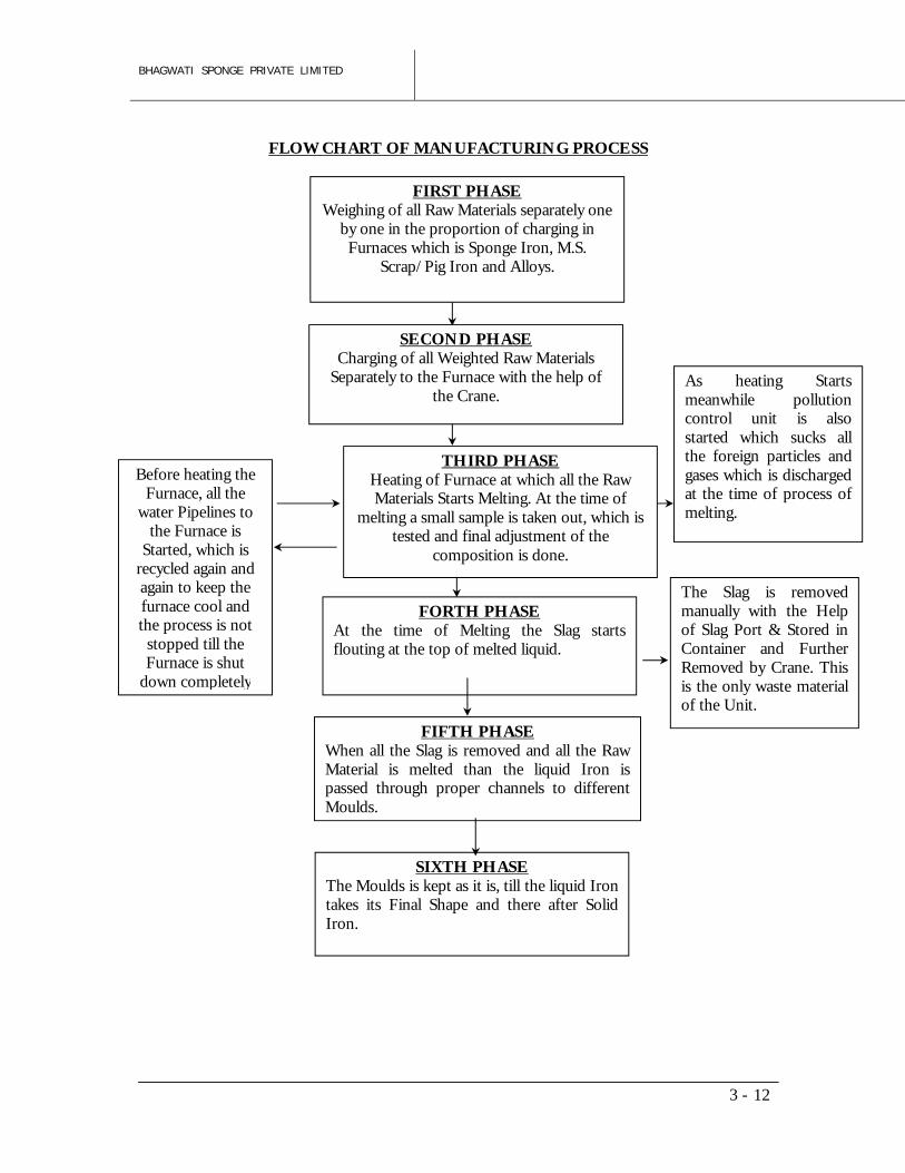
FLOW CHART OF MANUFACTURING PROCESS
FIRST PHASEWeighing of all Raw Materials separately one
by one in the proportion of charging in Furnaces which is Sponge Iron, M.S.
Scrap/Pig Iron and Alloys.
FORTH PHASEAt the time of Melting the Slag starts flouting at the top of melted liquid.
The Slag is removed manually with the Help of Slag Port & Stored in Container and Further Removed by Crane. This is the only waste material of the Unit.
Before heating the Furnace, all the
water Pipelines to the Furnace is
Started, which is recycled again and again to keep the furnace cool and the process is not stopped till the Furnace is shut
down completely
As heating Starts meanwhile pollution control unit is also started which sucks all the foreign particles and gases which is discharged at the time of process of melting.
FIFTH PHASEWhen all the Slag is removed and all the Raw Material is melted than the liquid Iron is passed through proper channels to different Moulds.
SIXTH PHASEThe Moulds is kept as it is, till the liquid Iron takes its Final Shape and there after Solid Iron.
SECOND PHASECharging of all Weighted Raw Materials
Separately to the Furnace with the help of the Crane.
THIRD PHASEHeating of Furnace at which all the Raw Materials Starts Melting. At the time of
melting a small sample is taken out, which is tested and final adjustment of the
composition is done.
BHAGWATI SPONGE PRIVATE LIMITED
3 -
13
The Conventional Method of Ingot / Billet Casting with the help of Induction
Furnace through Direct Teeming Practice or Ladle Teeming Practice have
its drawbacks and with the technology advancements, Continuous Casting
Machine is introduced for Billet Casting. The advantages of Continuous
Casting Machine in Billet casting over conventional methods are:
1. It dispenses with much of the auxiliary equipments and facilities like
Ingot Moulds, Mould Conditioning, Mould Yard, Liquid Metal Pouring
Platform, Teeming aisle, Ingot Bogies, Transfer Facilities, Stripping
Facilities, Stripper Cranes etc.
2. The yield is approx 97% of Finished Goods from Liquid Metal in CCM
in comparison of 93% in conventional method.
3. The conventional method does not allow active control of the primary
structure as solidification of liquid metal proceeds in Ingot moulds.
Ingots suffer from many defects like central porosity, non metallic
inclusion, V and inverted V segregation etc.
4. Material produced through CCM route has better grain structure as
compared to conventional route. This makes possible to impart, even
in a limited reduction in area, at the time of rolling. The necessary
degree of mechanical working and refinement of metallographic
structure contributing to the development of specified physical
properties in the Finished Products. The Ingots with same average
cross section, undergoing same reduction in the area.
5. In Alloy Steel, Double Rolling can be avoided with the Billets
produced through CCM route.
6. Billets produced through CCM route saves considerably in manpower
and energy consumption. It is much more economical from the point
of view of the end products, annual capacity and overall investment
costs.
3.1.3 ROLLING MILL
The company is planned to install the proposed Rolling Mill for production of 2,00,000 TPA Structural Steel, TMT Bars, Angles, Channels, Wire Rod as a finished product.
BHAGWATI SPONGE PRIVATE LIMITED
3 -
14
Hot rolling processRe-Heating Furnace is fired daily 4 hours before start up time of Rolling Mill. Ingots/Billets, when in the heating zone a temperature of 650°C is achieved, which is measured through Thermo Couples & in Soaking zone a temperature of 1250°C is achieved some sized samples approximately 1.5 m to 2 m long are put in & fed in every mill. This is already in running condition with all water circuitry on, to check the sizes on every pass. If some minute adjustment is required it is made & again samples are fed to confirm size of pass in Rolls, then 1st piece of Ingot is passed through & leader & tail end is cut in on line Rotary Shears & final size, which is put on cool Bed manual & again size is reconfirmed. Bar/ Structural material is cut into 48 M length through on line Rotary Shear before cooling Bed.
In the meantime charging Grate helpers put manually cold ingot or, which was stacked on charging Grate by EOT Electromagnetic Crane from stock Yard, to conveyor table which brings the piece in front of pusher on the back side of Re-Heating Furnace from where on getting signal from Ejector operator the pusher operator pushes the piece into the Furnace. In front side the Roughing pull pot operator gives Electric operated signal to ejector operator for pushing next piece and rolling of second piece stars, if rolling is going on without hindrance which is observed upto 10 approx. pieces the process become continuous. On an average when 8 MM size is being rolled & 3 Meter billet is use approximately 65-70 pieces come in one hour. Production increases for high sized sections 10 MM & above on Cooling Bed when quantity is collected, one piece of 48 M length is pushed manually/ automatically on pieces conveyor. Which when pass through cold shear is cut in to 12 M length & workers make bundles of these & stack these size wise for checking & dispatching.
3.1.4 FERRO ALLOYS PLANT The company is planning to install 2x9 MVA Submerged Arc Furnaces (SAFs) for production of 20,460 TPA Ferro Manganese or 14,850 TPA Silico Manganese or 6,600 TPA Ferro Silicon or 24,750 TPA Pig Iron as a finished product.
Most of the ferro-alloys e.g. Ferro-silicon, Ferro-manganese, Silico-manganese, etc. are produced by smelting process. Smelting of the charged materials are carried out in submerged electric furnaces equipped with transformer of proper ratings.
The process developed recently in India during the decade of 90 is based on basic process parameters as offered by ELKEM, Sweden, in past. Various Indian furnace manufacturers successfully developed furnace design upto 12.5 MVA electrical ratings for manufacture of different grades of ferro-alloys based on ELKEM, Sweden Technology.
BHAGWATI SPONGE PRIVATE LIMITED
3 -
15
Basic ProcessFerro-alloys are produced by reducing metals from their oxides contained in ores by using a suitable reductant under conditions created to ensure a high recovery of the valuable elements from the starting materials. Such reduction reactions are characterized by stability of all oxides at high temperatures. The stability of all oxides decreases with increasing temperatures, exception being only carbon mono-oxides which becomes more stable with increasing temperature. An element which forms a stronger oxide can, under appropriate conditions, be used as reductant for a less stronger oxide. The reaction will proceed successfully if the difference in free energies of oxidation reaction amounts to tens of Kilo-calories per mole of oxygen involved; with a small difference, favourable conditions should be formed to make the reaction proceed. The presence of iron or iron oxides can facilitate some reduction processes. Iron dissolves the reduced element, forms a compound with it, and thus lowers the activity of that element by removing it from the reaction zone. In many cases the melting point of an iron element alloy is lower than that of the pure element.
3.1.5 CAPTIVE POWER PLANT
A 18 MW captive power plant will be installed, out of which 10 MW will be generated based on waste heat recovery boiler and the balance 8 MW, based on AFBC boiler using dolochar from DRI plant & coal as fuel. The AFBC boiler has been proposed just to maintain the un-interrupted running and ultimately to sustain the turbine operation, as the proposed WHRB will not be able to maintain the consistent supply of steam to the turbine.
The steam generator shall be provided with one steam drum and the drum shall be fusion-welded type. The drum shall be provided with Torispherical / Semi–Ellipsoidal spinned dished ends. The steam drum shall be liberally sized to assure low steam space loading, with adequate space to accommodate the internals. The furnace envelop shall be constructed of fully water cooled membrane/fin welded walls and they shall be adequately supported. The construction shall be gas pressure tight and the furnace shall be strengthened by providing bucks trays and tie bar system. The furnace design shall incorporate necessary man holes. The boiler bank design shall be of inline arrangement and the tube spacing shall enable easy removal of the tubes in case of any failure. There shall be adequate approach space to the tubes of the bank for easy maintenance. Suitable numbers of soot blowers shall be provided to cover the maximum surface area of the bank. The sealing at the bank tube penetrations with the
BHAGWATI SPONGE PRIVATE LIMITED
3 -
16
boiler membrane wall shall be 100% leak tight. The tubes shall be of seamless construction. The steam generator shall be provided with a complete system of soot blowers to effectively dislodge deposits from heat transfer areas. The necessary pressure reducing station shall be provided. In the zones where the gas temperatures exceed 7000C only long retractable soot blowers shall be used.
Waste Heat Recovery Potential The 550 TPD capacity Sponge Iron Plant will produce waste gases, which will be able to generate around 10 MW of Electrical power.
The AFBC Boiler will use dolochar from DRI and coal.
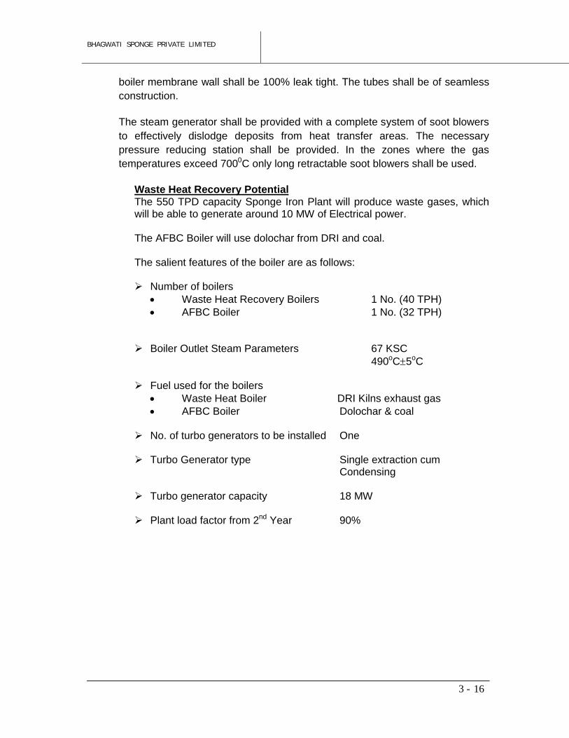
The salient features of the boiler are as follows:
Number of boilers Waste Heat Recovery Boilers 1 No. (40 TPH) AFBC Boiler 1 No. (32 TPH)
Boiler Outlet Steam Parameters 67 KSC 490oC5oC
Fuel used for the boilers Waste Heat Boiler DRI Kilns exhaust gas AFBC Boiler Dolochar & coal
No. of turbo generators to be installed One
Turbo Generator type Single extraction cumCondensing
Turbo generator capacity 18 MW
Plant load factor from 2nd Year 90%
BHAGWATI SPONGE PRIVATE LIMITED
4 - 1
4 – PLANT GENERAL LAYOUT & BUILDINGS
This chapter deals with the criteria for selection of the site and the general layout of the
proposed plant. The salient aspects of the plant general layout, viz. storage and handling of
the major input materials and proper location of the proposed units with respect to all requisite
facilities are discussed here. The availability of industrial infrastructural facilities has also been
noticed.
Selection of Plant Site
The following major factors demand consideration when selecting the site for proposed plant
with the requisite facilities, with provision for future expansion/ diversification:
i) Availability of adequate land for the proposed plant and its future rational expansion;
ii) Sources of supply of raw materials and their delivered cost;
iii) Proximity to finished goods;
iv) Existence of rail & road connection in the vicinity for transportation of incoming materials
and outgoing products
v) Availability of industrial infrastructural facilities, e.g. water, power, skilled personnel, etc.
vi) Access to developed areas with markets, schools, hospitals, and other social amenities;
and
vii) The effect of all these factors on the capital and operating cost, and ultimately on the
overall economics of the project.
The proposed plant will be located in 29.8 acres of land. In fact the entire area has been
developed by Asansol Durgapur Development Authority (ADDA) and therefore necessary
infra-structural facilities shall be available for the growth of the industries to be located in this
area. The proposed location enjoys the territorial advantage of being situated near the
National Highway as well as State Highways and therefore connected to most of the important
cities of the country. The site thus combines many advantages such as access to market,
transportation facilities, availability of manpower and other infrastructural facilities like
electrical power and an already established industrial environment. Water shall be made
available by ADDA as per the requirement.
BHAGWATI SPONGE PRIVATE LIMITED
4 - 2
Plant General Layout
The plant general layout has been designed to provide a rational disposition of production
facilities, material logistics facilities, auxiliary & ancillary facilities and plant utilities & services.
The layout has been developed in such a way that future expansion & diversification may be
readily feasible. A properly designed layout is obviously essential for operational efficiency,
plant economy and saving of capital cost.
In developing the plant general layout, the factors which have been taken into consideration
for appropriate flow of process materials are indicated below:
i) Economical and uninterrupted receipt of major incoming materials, in plant movement of
materials without hindrance and minimum counter-flow of materials particularly inside
the production shop in which major equipment is located.
ii) Logical locational arrangement of the proposed Units with respect to existing units,
supporting facilities, plant services and ancillary facilities so as to ensure minimum
capital and operating costs.
iii) Compactness of the plant layout minimizing inter plant building for processing materials
as well as adequate scope for future expansion.
iv) Maximum utilisation of the available facilities / services as are available in the existing
plant.
Of particular importance is the establishment of a correct spatial relationship between the
production facilities, material logistic facilities and auxiliary & ancillary facilities. Especially the
production shop must provide easy access to all other sections so as to allow unimpeded
movement of input materials and manufactured products. The production facilities, it may be
recalled will consist of proposed units, the utilities and auxiliary facilities will include the
electrical power system, water system, compressed air system, general store, etc. and the
ancillary facilities will comprise administrative building, ablution block, time & gate office, etc.
Taking all these aspects into consideration, an appropriate plant layout (ref. Figure-4.1) has
been developed.
BHAGWATI SPONGE PRIVATE LIMITED
5 –1
5 – MAJOR RAW MATERIALS
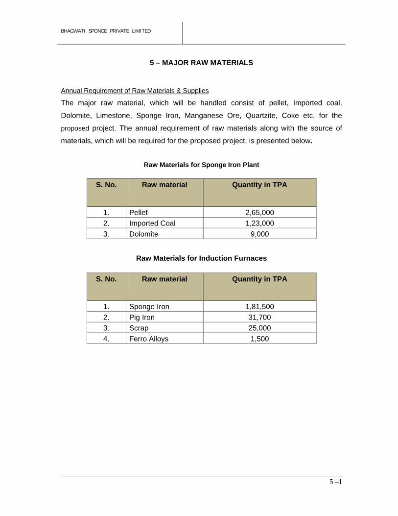
Annual Requirement of Raw Materials & Supplies
The major raw material, which will be handled consist of pellet, Imported coal,
Dolomite, Limestone, Sponge Iron, Manganese Ore, Quartzite, Coke etc. for the
proposed project. The annual requirement of raw materials along with the source of
materials, which will be required for the proposed project, is presented below.
Raw Materials for Sponge Iron Plant
Raw Materials for Induction Furnaces
S. No. Raw material Quantity in TPA
1. Pellet 2,65,000
2. Imported Coal 1,23,000
3. Dolomite 9,000
S. No. Raw material Quantity in TPA
1. Sponge Iron 1,81,500
2. Pig Iron 31,700
3. Scrap 25,000
4. Ferro Alloys 1,500
BHAGWATI SPONGE PRIVATE LIMITED
5 –2
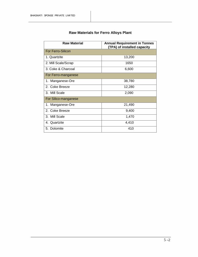
Raw Materials for Ferro Alloys Plant
Raw Material Annual Requirement in Tonnes(TPA) of installed capacity
For Ferro-Silicon
1. Quartzite 13,200
2. Mill Scale/Scrap 1650
3. Coke & Charcoal 6,600
For Ferro-manganese
1. Manganese-Ore 38,780
2. Coke Breeze 12,280
3. Mill Scale 2,090
For Silico-manganese
1. Manganese-Ore 21,490
2. Coke Breeze 9,400
3. Mill Scale 1,470
4. Quartzite 4,410
5. Dolomite 410
BHAGWATI SPONGE PRIVATE LIMITED
6 – 1
6 – MECHANICAL SERVICES
The essential mechanical services required for the proposed plant can be broadly classified
into four parts, viz –
1. Water System
2. Air System
3. Material Handling System
4. Fume Extraction/ Pollution Control System
Although the plant is proposed to be installed in the Jamuria Industrial Estate of West Bengal,
other Infrastructural facilities for the plant maintenance etc. are expected to be available in
and around the plant site. While an elaborate material handling system is required for the
plant operation, this will be the major part of the production facility and hence has been
included in the cost of the main plant and equipment and therefore has not been covered
separately as auxiliary equipment.
Water System
The water system of the proposed plant will provide for the following usages:
a) Cooling of equipments & DM Water
b) Human consumption for drinking, washing & sanitary needs
Generally the water for cooling of the equipment is circulated in a closed circuit. It is pumped
from the cold sump and sent to the equipments through necessary pipelines. After cooling
different parts of the equipments, the hot water returns to the top of cooling tower.
The required degrees of cooling of hot water are done through the cooling tower and it is
stored in the cold sump for recirculation. Some make up water is always necessary to be
added to the cold sump to compensate for evaporation loss, drift loss, process loss and
leakage loss. The water in the cooling system for the furnace and for compressors are
required to be treated to the levels as specified by the equipment manufacture.
The entire break-up of water requirement for equipment cooling system, general drinking,
sanitary and other miscellaneous purpose including related auxiliary facilities has been
discussed below.
BHAGWATI SPONGE PRIVATE LIMITED
6 – 2
In the proposed unit, water will be required mainly for the following:
IF/Submerged Arc Furnaces : Cooling of transformers, furnace mechanicals, viz. water
cooled jacketed furnace hood, electrode holder cooling,
water cooled guides, etc.
To minimize the requirement of cooling water, a recirculation system with replenishment by
make-up water will be adopted. The re-circulating routes of cooling water for the different
kinds of equipment are indicated below:
Equipment Circulation Routes
IF, Submerged Arc Furnace : Cold Sump – Equipment – Cooling Tower – Cold Sump& Air Compressor
During recirculation of the cooling water through the above systems certain unavoidable
losses will occur in the water flow circuits, because of evaporation in sumps, drift and leakage
losses in machinery as well as evaporation, drift and blow down/ bleed-off losses from cooling
towers. These losses in cooling tower circulation for the furnaces amounts to about 5%. Thus
a continuous supply of make-up water to replenish these losses will be required.
Turbine and Boiler Auxiliaries will be cooled by Cooling Water circulated with the help of
Cooling Water pumps. Hot Water coming out of the said Auxiliaries will be cooled in the
Cooling Tower. Small percentage of Cooling Water will be required to be blown down at
regular intervals to keep concentration within limit by supplying Make-up Water. Boiler
Blowdown Water will be collected in a pond for utilization in Coal Handling Plant, Dust
Suppression system within the Plant Premises.
To keep concentration of Boiler Water within limit, some percentage of Boiler water will be
blown down. This will require supply of DM Water for Make-up. DM Water shall be supplied
from DM Water Plant.
In addition, water will also be required for general drinking and sanitary purposes. It is
envisaged that the required quantity of total make-up water including that for drinking &
sanitary purposes will be available from an underground reservoir. Water from underground
reservoir will be pumped by suitable lift pump and after passing through water treatment plant
will be stored in the cold sump for recirculation. Drinking, laboratory & sanitary water needs to
be supplied after filtration & chlorination, if necessary.
BHAGWATI SPONGE PRIVATE LIMITED
6 – 3
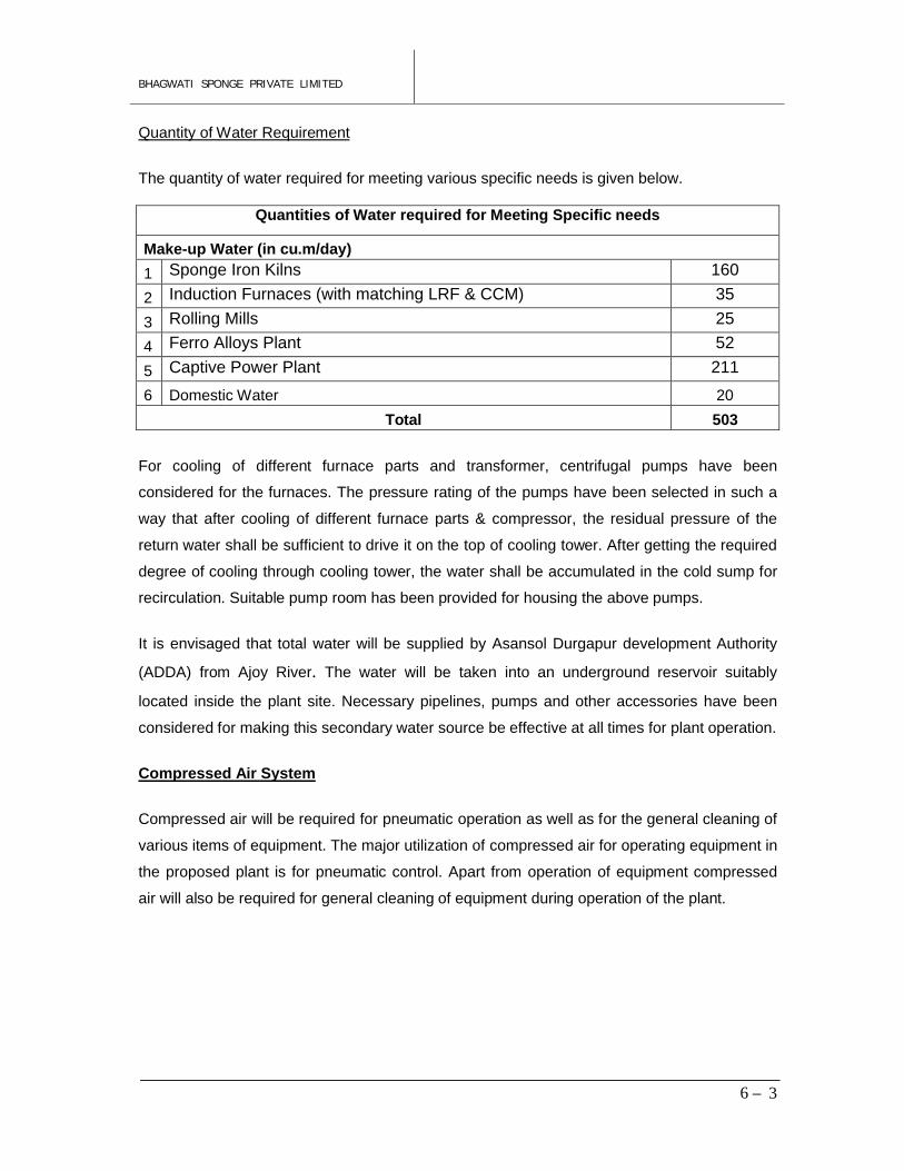
Quantity of Water Requirement
The quantity of water required for meeting various specific needs is given below.
Quantities of Water required for Meeting Specific needs
Make-up Water (in cu.m/day)
1 Sponge Iron Kilns 160
2 Induction Furnaces (with matching LRF & CCM) 35
3 Rolling Mills 25
4 Ferro Alloys Plant 52
5 Captive Power Plant 211
6 Domestic Water 20
Total 503
For cooling of different furnace parts and transformer, centrifugal pumps have been
considered for the furnaces. The pressure rating of the pumps have been selected in such a
way that after cooling of different furnace parts & compressor, the residual pressure of the
return water shall be sufficient to drive it on the top of cooling tower. After getting the required
degree of cooling through cooling tower, the water shall be accumulated in the cold sump for
recirculation. Suitable pump room has been provided for housing the above pumps.
It is envisaged that total water will be supplied by Asansol Durgapur development Authority
(ADDA) from Ajoy River. The water will be taken into an underground reservoir suitably
located inside the plant site. Necessary pipelines, pumps and other accessories have been
considered for making this secondary water source be effective at all times for plant operation.
Compressed Air System
Compressed air will be required for pneumatic operation as well as for the general cleaning of
various items of equipment. The major utilization of compressed air for operating equipment in
the proposed plant is for pneumatic control. Apart from operation of equipment compressed
air will also be required for general cleaning of equipment during operation of the plant.
BHAGWATI SPONGE PRIVATE LIMITED
6 – 4
Material Handling System
The plant shall be provided with material handling system for uninterrupted supply of raw
material to the proposed units. The system will however, consist of the following basic
equipment.
1. Vibrating screen for feeding to the belt conveyor;
2. Belt conveyor for transfer of material from raw material storage area to day bins;
3. Fabricated day bins;
4. Load cells and transfer conveyor for feeding of raw materials to skip hoist;
5. Skip hoist, transfer cars, monorails for transfer and feeding of raw material to charging
bins;
6. Charging bins and chutes with flow control/ regulation valves for storage & charging of
mixed raw materials to the furnace.
Bulk raw material will be handled by means of Dumper Trucks & Pay Loaders and proposed
arrangement has been considered to be adequate for handling the raw material for all the
furnaces.
Fume Extraction/ Pollution Control System
Adequate control measures like installation of electrostatic precipitator (ESP), bag filters, dust
suppression system to limit the outlet emission of particulate matters to 50 mg/Nm3.
There will be Dust Extraction/Dust Suppression Systems/Foggy Dust Arresters to control
fugitive emissions at Furnace Tapping Points, raw material handling section and various other
facilities inside the plant. Besides, there will arrangement for mobile water sprinkler for the
dust suppression at all relevant places including internal roads of the plant.
Fume extraction system has now become a statutory obligation in the various industries
specially in a melting or smelting unit. In order to minimize the abuse of the environment
prevailing in the Smelting Shop, a system has been proposed by which fumes are to be
sucked through suction hoods and the hood is required to be located immediately above the
fume generating zone. In the proposed plant, fume shall be generated in the furnaces so long
as smelting process runs. Fumes generated shall be sucked through a hood/ canopy suitably
located just above the main furnace mouth and shall be carried away by means of blower
through ducting system and bag filter to the chimney for discharging it to the atmosphere. The

BHAGWATI SPONGE PRIVATE LIMITED
6 – 5
system shall comprise Hood / Canopy, Duct, Exhaust Blower, Bag Filter, Chimney and other
accessories.
BHAGWATI SPONGE PRIVATE LIMITED
7 – 1
7 – PLANT CONSTRUCTION
Installation of the equipment and systems of a plant and construction of the plant & ancillary
buildings, utilities & services and auxiliary facilities demand coordination of various activities
like procurement of equipment and materials of construction, designing the plant and other
buildings, award of contracts and supervision of all construction jobs at site.
Considering the delivery period of major equipment and the time required for construction of
buildings and miscellaneous items as well as for installation of machinery & equipment, a
project implementation schedule has to be developed. The factors involved in the execution of
this schedule are discussed in the following sections.
Steps involved in implementation
It is estimated that the implementation of this project will take around 18 months if the jobs are
executed efficiently and as far as practicable simultaneously. The major steps involved in the
implementation of proposed expansion project making facilities are: -
i) Arrangement of the requisite finance for the project
ii) Finalisation of the layout of the proposed plant
iii) Completion of site survey and soil testing, design of all plant buildings, auxiliary &
ancillary buildings, utilities & services.
iv) Issue of tender documents and specifications for all equipment, selection of equipment
supplier and placement of orders.
v) Finalisation of arrangement for the construction of the substation for electric power
supply system.
For the constructional jobs and for bringing the plant into operation, the following major steps
are needed:
a) Arranging for all constructional facilities at site
b) Procurement of bulk steel, cement and other construction materials and arranging for
their delivery in accordance with the construction schedule.
c) Creating an organizational set up for the execution of the project.
d) Obtaining foundation load and other relevant data of the major plant & machinery etc.
e) Preparation of Tender documents for construction.
BHAGWATI SPONGE PRIVATE LIMITED
7 – 2
f) Issue of Tender documents and selection of contractors for handling civil, structural,
mechanical & electrical jobs and equipment installation.
g) Installation & erection of equipment including power supply and distribution system,
water system and other utilities.
h) Securing personnel for the operation of the plant.
i) Arranging for necessary raw materials and services.
j) Trial run & commissioning of the individual items of equipment and finally the entire
plant.
Project Implementation Schedule
Commissioning
It has been planned to complete the installation and commissioning of the proposed plant
within 18 months of “go-ahead”. The construction schedule has been prepared on the basis of
the delivery periods of the major items of equipment as indicated by the supplier and the
volume of civil, mechanical and constructional jobs involved. In view of the long delivery
periods of some of the major items, particularly the submerged arc furnace, material handling
equipment, pollution control equipment, etc. It is imperative to finalise orders for them at the
initial stage of the project. The delivery of the components of these major items should be so
in order that their assembly at the plant site may not suffer.
Procurement of Equipment & Installation
The delivery period of the furnaces & other equipment will be 8-9 months. The next long
delivery items are the material handling equipment, electrical equipment, cranes and the water
pump sets; all of which may take 6 to 8 months for delivery. Pending the delivery of these
items, all such work as the laying of cables, pipelines for water systems, compressed air
systems should be taken up and completed by the time equipment is installed and test trial
run may commence as per schedule.
Civil Work
The soil testing data should be made available at the earliest. On the basis of soil data, the
columns and other structural for all the buildings can be designed. The foundation of the
columns of all buildings should be started immediately after the go-ahead signal and
completion of leveling of the site. The civil & structural construction of all the building sheds
can proceed simultaneously. On receipt of foundation load and other data, laying of
foundation for the furnaces and other items of equipment can be taken up simultaneously and
BHAGWATI SPONGE PRIVATE LIMITED
7 – 3
completed before the equipment arrive at site. The laying of internal roads & drainage system
should be completed and made ready to facilitate transportation of structural material, raw
materials and equipment.
Structural Steelwork
An appropriate & economical structural design of the plant buildings will be adopted and the
required quantity of structural steel and other building materials should be procured after the
“go-ahead” decision has been taken. Along with the civil work, the fabrication of column, roof
trusses, etc. can be started. The fabrication & erection of structural steelwork including roofing
& cladding should be completed within the allocated time.
Equipment Erection
The erection of the submerged arc furnace should be carried out under the guidance &
supervision of the personnel deputed by the equipment supplier, who will also be responsible
for commissioning of the equipment & demonstrating the fulfillment of performance
guarantees.
Management of the Project
It is necessary to fix responsibilities for the project management on suitable persons headed
by a Chief of Project who will monitor the progress of work and take proper steps for its timely
completion. The critical factors that may cause delay should be identified at an early stage of
implementation and necessary steps should be taken to overcome the obstacles. It needs
emphasizing that delay in execution of the inter-related jobs will increase the capital cost and
therefore all likely delays should be avoided so that the project may not over run. Delays in
completion of a project lead to enormous escalation in capital cost and instead of bringing in
revenue it causes loss of earnings to the company. If needed, a task force can be formed for
timely execution of the full project.
BHAGWATI SPONGE PRIVATE LIMITED
8 - 1
8 – ORGANISATION & MANPOWER REQUIREMENT
The efficient management of proposed units demands judicious manpower planning, selection
of qualified & experienced personnel and an appropriate organizational structure clearly
defining the functions & responsibilities of individual, managerial & supervisory staff of various
level, dealing with secretarial & administration, financial & budgetary control, purchase, sales,
plant operation & maintenance, quality control, personnel management & discipline, plant
safety, etc.
The estimated requirement of manpower of the proposed plant in the various departments has
been worked out purely on technical & management grounds.
Basis of Manpower Estimation
The manpower requirement has been estimated on the following basis:
i) the anticipated production and productivity level achievable in various sections of the
plant with its installed equipment, supporting facilities and routine production norms;
ii) number of personnel required to perform various duties associated with the different
processing steps leading to the production, maintenance of equipment, services &
utilities, auxiliary facilities, quality control and all other related jobs;
iii) requirement of personnel for secretarial, administration, budgetary & finance control,
purchase of input materials and sale of manufactured products, security & labour
welfare.
For realistic estimate of manpower, an appropriate organization structure demarcating the
duties & responsibilities of individual senior plant personnel engaged in a specific job needs to
be considered. It will be considered that the head of the organization will be the Chief General
Manager who will formulate policies and exercise overall management control. He will be
assisted by Works Manager for all technical matters relating to the plant operation and its
maintenance and Company Secretary dealing with personnel management, administration,
legal, secretarial, finance, etc.
BHAGWATI SPONGE PRIVATE LIMITED
8 - 2
Works Manager
The Works Manager will be accountable and answerable to the Chief General Manager for all
operations including planning, purchase, material management, production, plant utilities,
maintenance, quality control, production cost and budgetary control, plant safety, discipline,
labour relation, dispatches of finished goods. He should solve technical problems and
exercise operational and administrative control of the plant. His main function should be to
ensure achievement of quality & quantity targets of production at reasonable cost and should
constantly strive to improve plant performance.
Maintenance Manager
The Maintenance Manager shall be responsible for the maintenance and installation of all
mechanical & electrical equipment of the plant. He is accountable to the Works Manager. He
should undertake preventive maintenance services regularly to minimize break-down. He
should arrange for timely procurement of spares.
Quality Control Manager
The Quality Control Manager will be responsible for ensuring the required quality of the end
product. He will work in co-operation with the Works Manager and will be assisted by Quality
Control Officers.
Foreman (Production)
The shift Foreman (Production) is in-charge of manufacturing facilities and supporting
equipment. He should be responsible for operation, administration & discipline of the
production shop and accountable to Works Manager. He shall be responsible for timely
procurement of all spares and efficient operation of the shop. He should work in collaboration
with the Maintenance Department to solve all maintenance problems so that frequent failure of
plant & equipment does not impede production.
BHAGWATI SPONGE PRIVATE LIMITED
8 - 3
Personnel of Various Categories
The personnel of various categories and disciplines required for integrated operation,
functional activity should be main criteria in the discharge of duties and selection of staff at
different levels. In order to provide incentive to the staff and workers, the production chain has
to be kept in view.
Estimate of Manpower Requirement
A preliminary estimate of manpower requirement for smooth and efficient operation of various
sections of the plant & services, administrative & commercial departments has been prepared
purely on technical and management grounds primarily to indicate the order of manpower
requirement and to make preliminary estimate of the annual salary & wage bill, which will
reflect on the production cost estimate. In estimating the manpower requirement, the proper
ratio between the administrative, managerial, supervisory and shop floor staff has been
maintained. The estimated manpower required for smooth operation of the plant is around
500.
BHAGWATI SPONGE PRIVATE LIMITED
9 - 1
9 – CAPITAL COST ESTIMATE
This Chapter deals with the capital cost estimate for the proposed units along with other
auxiliary facilities. The cost associated with the proposed installation for manufacture of
sponge iron, Billets, ferro-alloy etc. construction of production buildings, auxiliary & ancillary
buildings and miscellaneous civil construction, installation of basic & auxiliary production
equipment, plant services & utilities and contingency & escalation provision have been
considered for estimation of plant cost. The cost to be incurred on other items such as
engineering & consultancy charges, preliminary expenses, preoperative & start-up expenses,
interest during construction period, power connection charges & security deposit to DVC,
margin money for working capital, etc. are added to the plant cost to arrive at the total
investment.
Plant Cost
The plant cost has been estimated on the basis of the designed capacity and manufacturing
process proposed to be adopted as discussed in earlier chapters. The equipment cost is
based on recent quotations from reputed manufacturers/dealers and provisions have been
kept for escalation as well as contingency. The cost of construction is based on current rates
of civil & structural construction in West Bengal.
Land & Land Development
The company has already in possession of about 29.8 acres of land for the proposed project.
Civil & Structural Work
The estimates for civil & structural work are based on estimates on quantities of the major
items of work as derived from preliminary design as well as the unit rates and prevailing cost
of construction materials and erection charges in West Bengal.
Plant & Machinery
The cost estimates of the plant & machinery are based on recent available quotations
received from various manufacturers for the proposed scheme and out of the quotations
received from different equipment manufacturers, only the most suitable quoted price has
been considered for the estimates.
BHAGWATI SPONGE PRIVATE LIMITED
9 - 2
Miscellaneous Fixed Assets
The cost of miscellaneous fixed assets comprising of utilities, services, testing, etc. has been
considered on the capital cost estimate.
Foundation & Erection
The cost of foundation & erection of plant & machinery has already been incorporated while
computing the cost of plant & machinery and foundation & erection cost has not been shown
separately.
Contingency & Escalation
A provision of about 3% of the Direct Cost has been kept towards contingency and price
escalation.
Total Investment
Various expenses such as preliminary & pre-operative expenses including interest during
construction period and start-up expenses, service connection charges and security deposit
for supply of electric power, margin money for working capital, etc. have to be added to the
plant cost to arrive at the total investment. The estimated Total Investment will be around Rs
324.0 Crores.