BGP DDoS Mitigation - RIPE 66 · PDF fileBGP DDoS Mitigation Gunter Van de Velde Sr Technical...
36
© 2012 Cisco and/or its affiliates. All rights reserved. 1 BGP DDoS Mitigation Gunter Van de Velde Sr Technical Leader NOSTG, Cisco Systems May 2013
Transcript of BGP DDoS Mitigation - RIPE 66 · PDF fileBGP DDoS Mitigation Gunter Van de Velde Sr Technical...
© 2012 Cisco and/or its affiliates. All rights reserved. 1
BGP DDoS Mitigation
Gunter Van de Velde Sr Technical Leader NOSTG, Cisco Systems May 2013
© 2012 Cisco and/or its affiliates. All rights reserved. Cisco Public
A simple DDoS mitigation mechanism explained Bertrand Duvivier, [email protected] Gunter Van de Velde, [email protected]
© 2012 Cisco and/or its affiliates. All rights reserved. Cisco Public
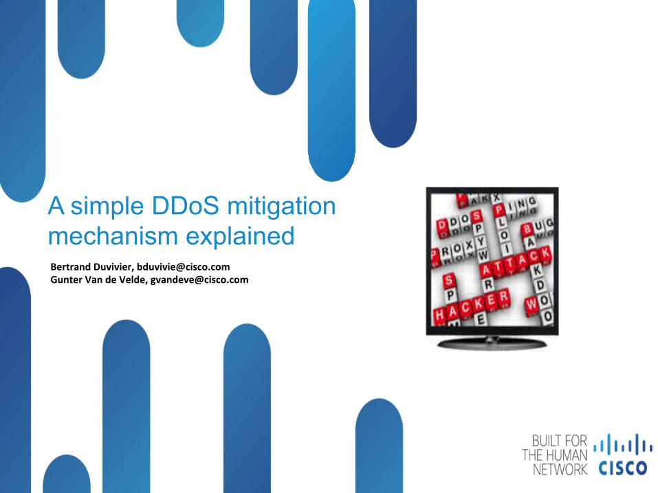
DDoS Mitigation Adoption Cycle
q Phase III o Dynamic application aware redirection and traffic handling
q Phase II o Malicious traffic mitigation
o Cleaning of Malicious traffic
o Dirty and clean traffic handling
o Usage of Multi-instance BGP
q Phase I o ACL
o RTBH
o PBR
o uRPF
© 2012 Cisco and/or its affiliates. All rights reserved. Cisco Public
DDoS Overview
Distributed denial-of-service (DDoS) attacks target network infrastructures or computer services by sending overwhelming number of service requests to the server from many sources.
Server resources are used up in serving the fake requests resulting in denial or degradation of legitimate service requests to be served
Addressing DDoS attacks Detection – Detect incoming fake requests Mitigation
Diversion – Send traffic to a specialized device that removes the fake packets from the traffic stream while retaining the legitimate packets
Return – Send back the clean traffic to the server
© 2012 Cisco and/or its affiliates. All rights reserved. Cisco Public
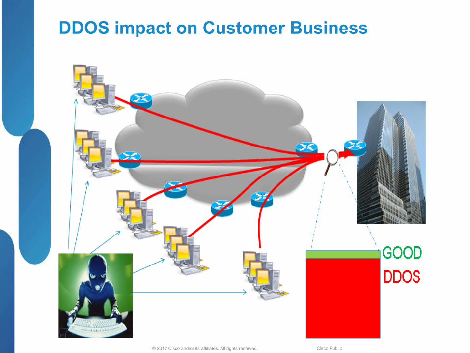
DDOS impact on Customer Business
© 2012 Cisco and/or its affiliates. All rights reserved. Cisco Public
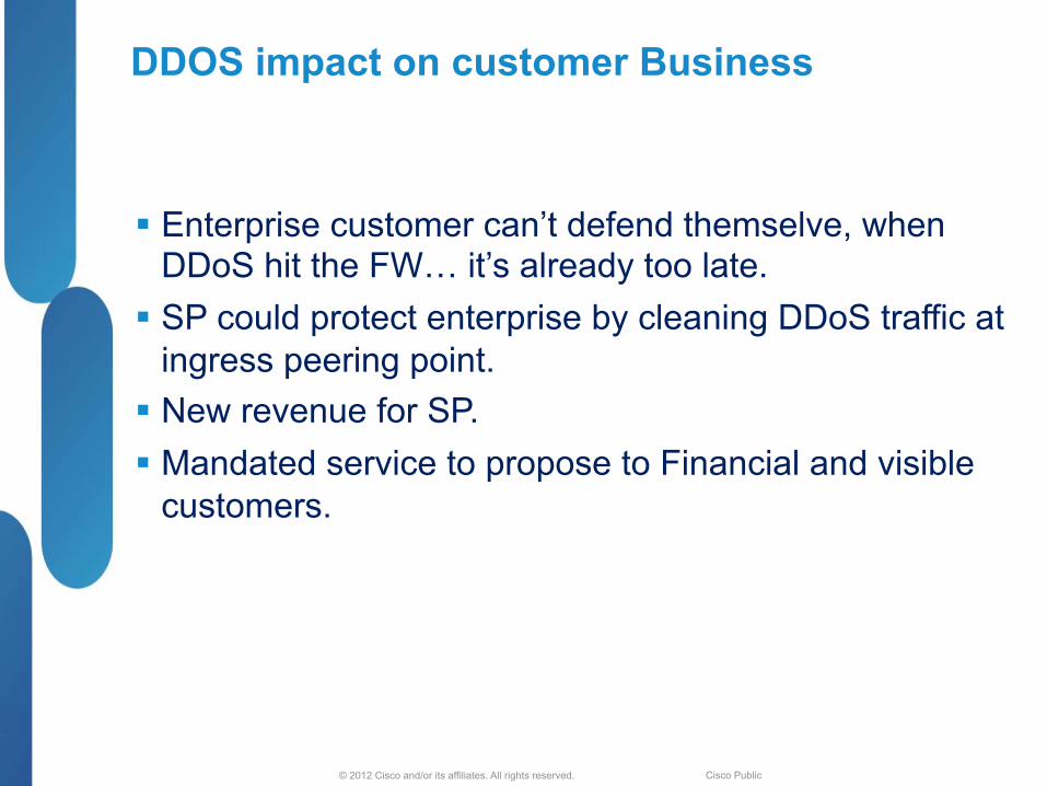
DDOS impact on customer Business
§ Enterprise customer can’t defend themselve, when DDoS hit the FW… it’s already too late.
§ SP could protect enterprise by cleaning DDoS traffic at ingress peering point.
§ New revenue for SP. § Mandated service to propose to Financial and visible
customers.

© 2012 Cisco and/or its affiliates. All rights reserved. Cisco Public
2011 DDoS trends (Nanog source)
§ Any Internet Operator Can Be a Target for DDoS
Ideologically-motivated ‘Hacktivism’ and On-line vandalism DDoS attacks are the most commonly identified attack motivations
§ Size and Scope of Attacks Continue to Grow at an Alarming Pace
High-bandwidth DDoS attacks are the ‘new normal’ as over 40% of respondents report attacks greater than 1 Gbps and 13% report attacks greater than 10Gbps
Increased sophistication and complexity of layer-7 DDoS attacks, multi-vector DDoS attacks becoming more common
§ First-Ever Reports of IPv6 DDoS Attacks 'in the Wild' on Production Networks

© 2012 Cisco and/or its affiliates. All rights reserved. Cisco Public
DDoS mitigation architecture 1. Detection (no DDoS)
DDOS scrubber
Security Server
DDOS Analyser
Sample Ne)low
Scan Ne)low data to detect DDOS a2acks
© 2012 Cisco and/or its affiliates. All rights reserved. Cisco Public
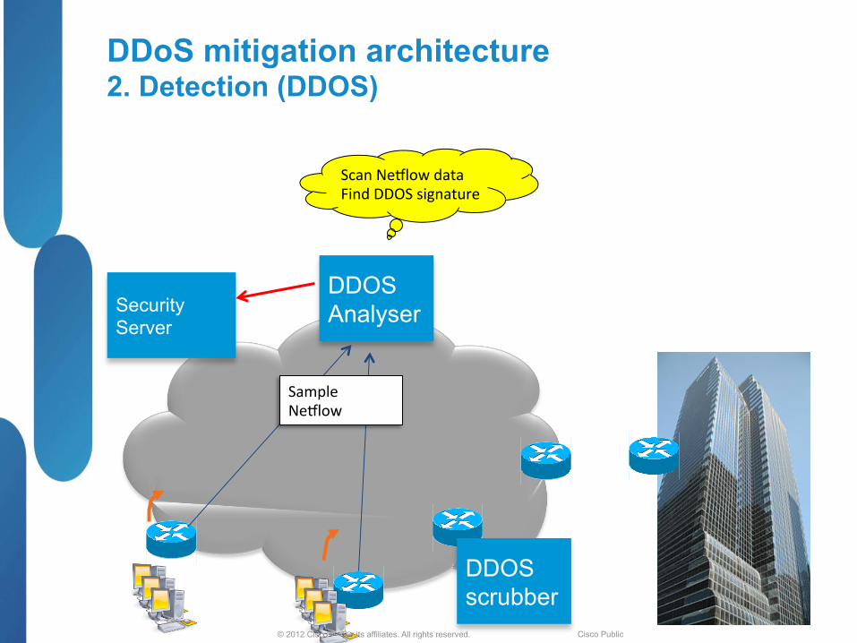
DDoS mitigation architecture 2. Detection (DDOS)
DDOS scrubber
Security Server
DDOS Analyser
Sample Ne)low
Scan Ne)low data Find DDOS signature
© 2012 Cisco and/or its affiliates. All rights reserved. Cisco Public
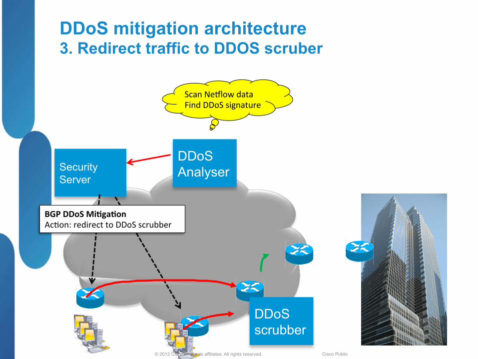
DDoS mitigation architecture 3. Redirect traffic to DDOS scruber
DDoS scrubber
Security Server
DDoS Analyser
Scan Ne)low data Find DDoS signature
BGP DDoS Mi<ga<on Ac;on: redirect to DDoS scrubber

© 2012 Cisco and/or its affiliates. All rights reserved. Cisco Public
DDoS Mitigation: Architecture Considerations
§ Normal traffic flow when there is no attack § Redirect traffic from any edge PE to any specific DDoS scrubber
Including the PE that is connected to the host network
§ Granular (prefix level/network) diversion Customers buy DDoS mitigation service for some prefixes
Pre-provisioned DDoS service for those prefixes (using policy such as standard community flag)
§ Centralized controller that injects the diversion route § VPN based Labeled return path for the clean traffic
To prevent routing loops
§ Solution support redirection of BGP less/more specific prefixes or local originated prefixes (static route, redistributed route)
§ Support for multi-homed customers During attack, send clean traffic from DDOS scrubber to multiple PE’s
© 2012 Cisco and/or its affiliates. All rights reserved. Cisco Public
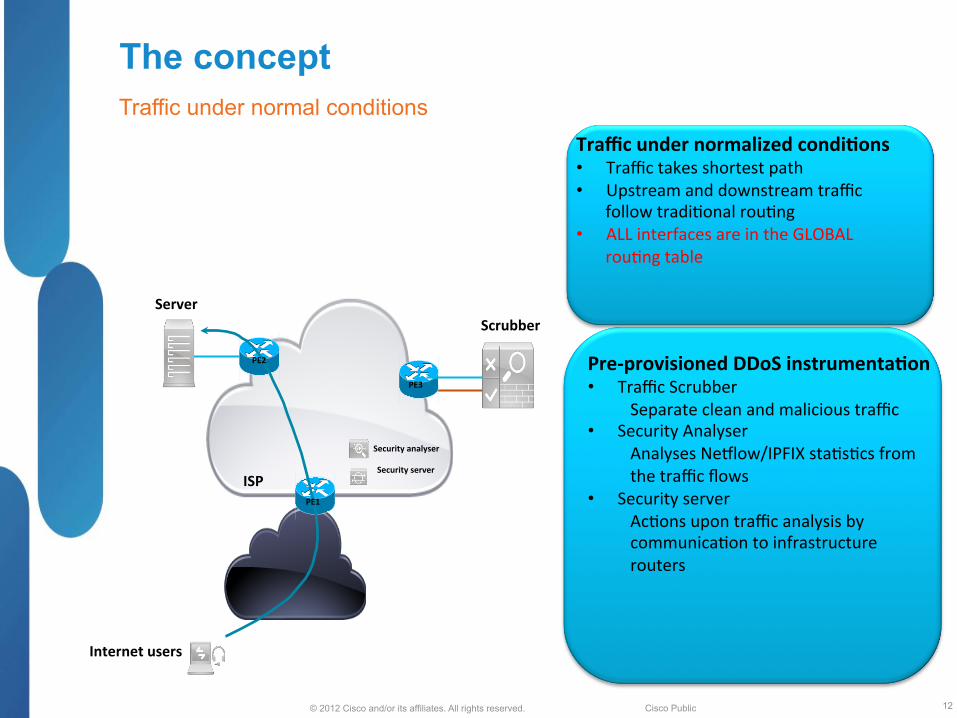
The concept Traffic under normal conditions
12
Internet users
Traffic under normalized condi<ons • Traffic takes shortest path • Upstream and downstream traffic
follow tradi;onal rou;ng • ALL interfaces are in the GLOBAL
rou;ng table
Server Scrubber
ISP
Pre-‐provisioned DDoS instrumenta<on • Traffic Scrubber
Separate clean and malicious traffic • Security Analyser
Analyses Ne)low/IPFIX sta;s;cs from the traffic flows
• Security server Ac;ons upon traffic analysis by communica;on to infrastructure routers
Security analyser
Security server
PE3
PE2
PE1

© 2012 Cisco and/or its affiliates. All rights reserved. Cisco Public
Phase-1: Traditional DDoS mitigation Traffic under DDoS condition - RTBH
13
Internet users
Traffic under DDoS condi<on • Security analyser detected that the
traffic flow is dirty • Security server installs a filter upon ISP
ingress router • All (good and malicious) traffic is
dropped at network ingress • Opera;onally simple method • Easy to remove filter if traffic
normalizes • Simple to debug and troubleshoot
Server Scrubber
ISP
Security analyser
Security server
PE3
PE2
PE1
© 2012 Cisco and/or its affiliates. All rights reserved. Cisco Public
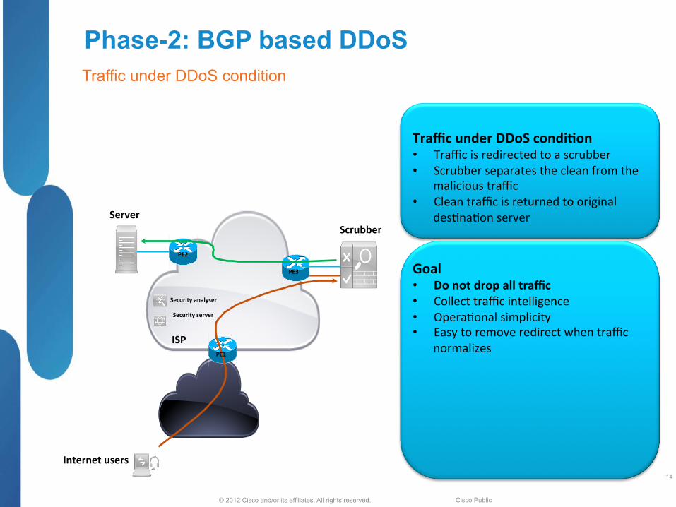
Phase-2: BGP based DDoS Traffic under DDoS condition
14
Internet users
Traffic under DDoS condi<on • Traffic is redirected to a scrubber • Scrubber separates the clean from the
malicious traffic • Clean traffic is returned to original
des;na;on server
Goal • Do not drop all traffic • Collect traffic intelligence • Opera;onal simplicity • Easy to remove redirect when traffic
normalizes
Server Scrubber
ISP
Security analyser
Security server
PE3
PE2
PE1
© 2012 Cisco and/or its affiliates. All rights reserved. Cisco Public
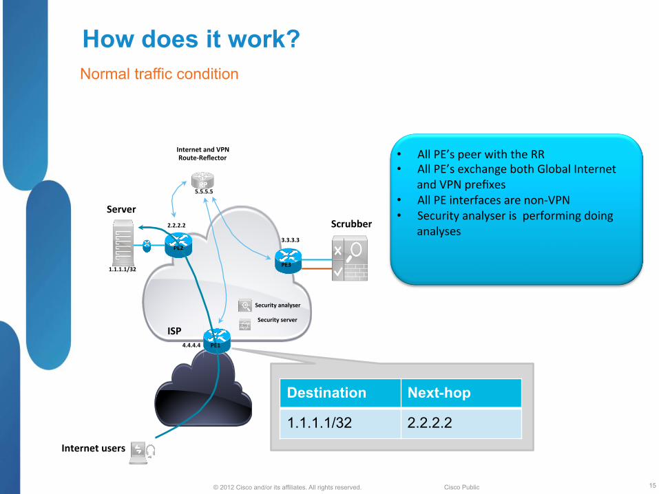
How does it work? Normal traffic condition
15
Internet users
• All PE’s peer with the RR • All PE’s exchange both Global Internet
and VPN prefixes • All PE interfaces are non-‐VPN • Security analyser is performing doing
analyses
Server Scrubber
ISP
Internet and VPN Route-‐Reflector
1.1.1.1/32
2.2.2.2
3.3.3.3
4.4.4.4
5.5.5.5
Security analyser
Security server
Destination Next-hop
1.1.1.1/32 2.2.2.2
PE3
PE2
PE1
© 2012 Cisco and/or its affiliates. All rights reserved. Cisco Public
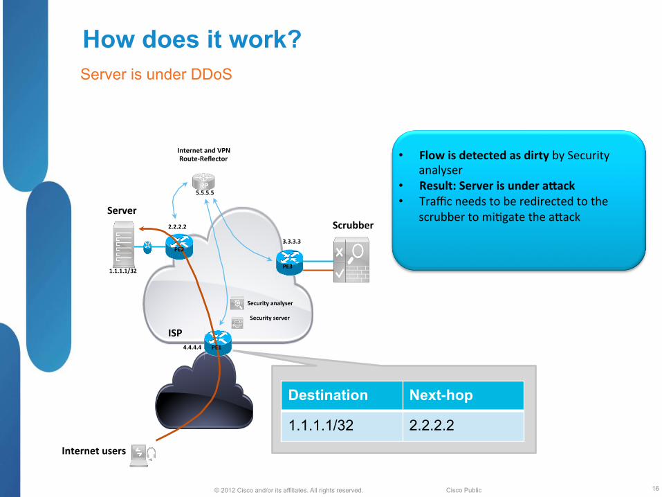
How does it work? Server is under DDoS
16
Internet users
• Flow is detected as dirty by Security analyser
• Result: Server is under aRack • Traffic needs to be redirected to the
scrubber to mi;gate the a2ack Server Scrubber
ISP
Internet and VPN Route-‐Reflector
1.1.1.1/32
2.2.2.2
3.3.3.3
4.4.4.4
5.5.5.5
Security analyser
Security server
Destination Next-hop
1.1.1.1/32 2.2.2.2
PE3
PE2
PE1

© 2012 Cisco and/or its affiliates. All rights reserved. Cisco Public
How does it work? Server is under DDoS
17
Internet users
• DDoS Route-‐Reflector was pre-‐visioned • Mi;ga;on route to 1.1.1.1/32 is
injected on the DDoS RR by the Security server
• Mi;ga;on route to 1.1.1.1/32 is poin;ng to 3.3.3.3 on DDoS mi;ga;on RR
Server Scrubber
ISP
Internet and VPN Route-‐Reflector
1.1.1.1/32
2.2.2.2
3.3.3.3
4.4.4.4
5.5.5.5
Security server
DDoS Route-‐Reflector
5.5.5.5
Destination Next-hop
1.1.1.1/32 3.3.3.3
PE3
PE2
PE1
© 2012 Cisco and/or its affiliates. All rights reserved. Cisco Public
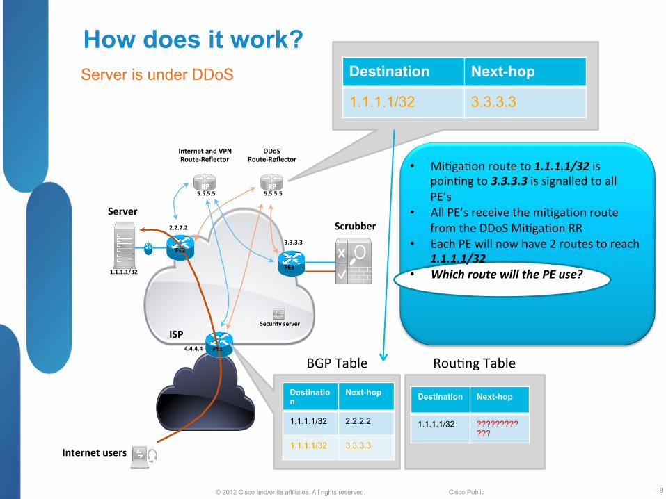
How does it work? Server is under DDoS
18
Internet users
• Mi;ga;on route to 1.1.1.1/32 is poin;ng to 3.3.3.3 is signalled to all PE’s
• All PE’s receive the mi;ga;on route from the DDoS Mi;ga;on RR
• Each PE will now have 2 routes to reach 1.1.1.1/32
• Which route will the PE use?
Server Scrubber
ISP
Internet and VPN Route-‐Reflector
1.1.1.1/32
2.2.2.2
3.3.3.3
4.4.4.4
5.5.5.5
Security server
DDoS Route-‐Reflector
5.5.5.5
Destination Next-hop
1.1.1.1/32 3.3.3.3
Destination
Next-hop
1.1.1.1/32 2.2.2.2
1.1.1.1/32 3.3.3.3
Destination Next-hop
1.1.1.1/32 ????????????
BGP Table Rou;ng Table
PE3
PE2
PE1

© 2012 Cisco and/or its affiliates. All rights reserved. Cisco Public
How does it work? Server is under DDoS
19
Internet users
Trick # 1 • The DDoS mi<ga<on route will
ALWAYS be preferred, even if • Both prefix lengths are the same • DDoS prefix is shorter • Original prefix has be2er
administra;ve distance Server
Scrubber
ISP
Internet and VPN Route-‐Reflector
1.1.1.1/32
2.2.2.2
3.3.3.3
4.4.4.4
5.5.5.5
Security server
DDoS Route-‐Reflector
5.5.5.5
Destination
Next-hop
1.1.1.1/32 2.2.2.2
1.1.1.1/32 3.3.3.3
Destination Next-hop
1.1.1.1/32 3.3.3.3
Rou;ng Table BGP Table
PE3
PE2
PE1

© 2012 Cisco and/or its affiliates. All rights reserved. Cisco Public
How does it work? Server is under DDoS
20
Internet users
• The mi;gated traffic flows towards PE3 (3.3.3.3)
• PE3 is sending the dirty flow towards the scrubber
• The scrubber will • Handle and remove the dirty
traffic within the original flow • Send the cleaned traffic towards
the original des;na;on (1.1.1.1 at PE2 (2.2.2.2))
Server Scrubber
ISP
Internet and VPN Route-‐Reflector
1.1.1.1/32
2.2.2.2
3.3.3.3
4.4.4.4
5.5.5.5
DDoS Route-‐Reflector
5.5.5.5
Destination
Next-hop
1.1.1.1/32 2.2.2.2
1.1.1.1/32 3.3.3.3
Destination Next-hop
1.1.1.1/32 3.3.3.3
Rou;ng Table BGP Table
PE3
PE2
Clean traffic
PE1
© 2012 Cisco and/or its affiliates. All rights reserved. Cisco Public
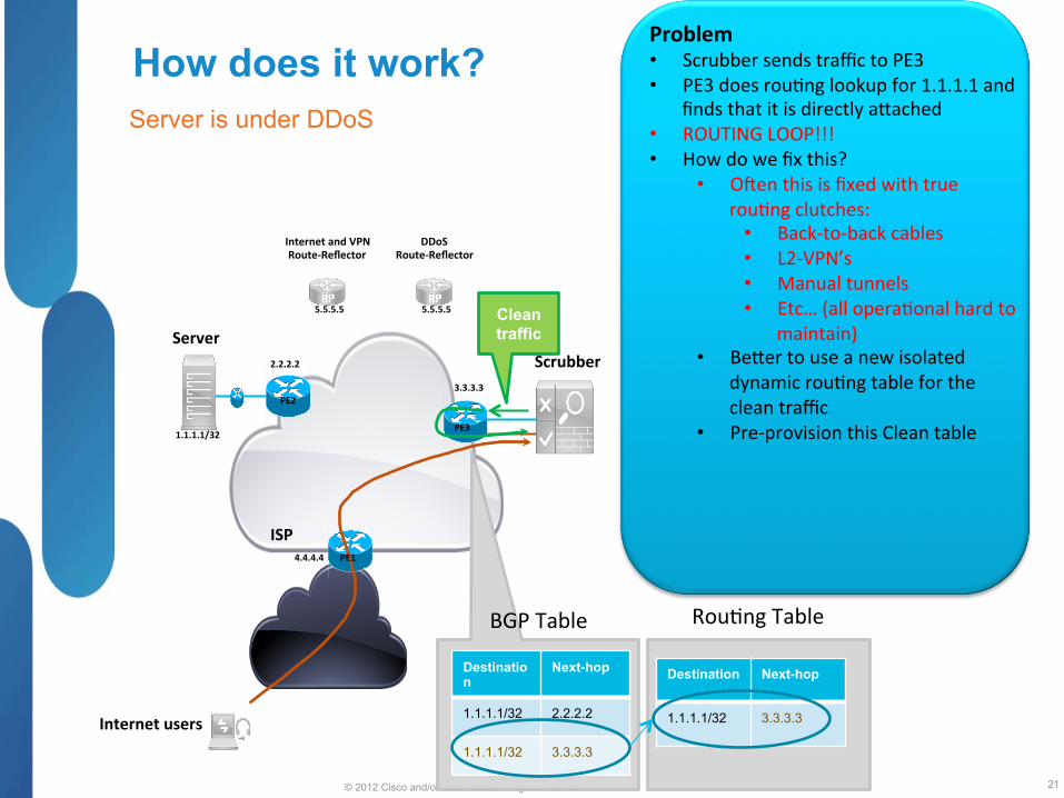
How does it work? Server is under DDoS
21
Internet users
Problem • Scrubber sends traffic to PE3 • PE3 does rou;ng lookup for 1.1.1.1 and
finds that it is directly a2ached • ROUTING LOOP!!! • How do we fix this?
• Ocen this is fixed with true rou;ng clutches:
• Back-‐to-‐back cables • L2-‐VPN’s • Manual tunnels • Etc… (all opera;onal hard to
maintain) • Be2er to use a new isolated
dynamic rou;ng table for the clean traffic
• Pre-‐provision this Clean table
Server Scrubber
ISP
Internet and VPN Route-‐Reflector
1.1.1.1/32
2.2.2.2
3.3.3.3
4.4.4.4
5.5.5.5
DDoS Route-‐Reflector
5.5.5.5
Destination
Next-hop
1.1.1.1/32 2.2.2.2
1.1.1.1/32 3.3.3.3
Destination Next-hop
1.1.1.1/32 3.3.3.3
Rou;ng Table BGP Table
PE3
PE2
Clean traffic
PE1
© 2012 Cisco and/or its affiliates. All rights reserved. Cisco Public
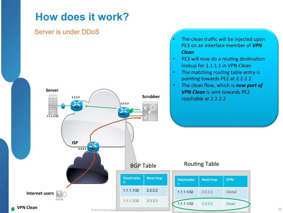
How does it work? Server is under DDoS
22
Internet users
Server Scrubber
ISP
1.1.1.1/32
2.2.2.2
3.3.3.3
4.4.4.4
Destination
Next-hop
1.1.1.1/32 2.2.2.2
1.1.1.1/32 3.3.3.3
Destination
Next-hop VPN
1.1.1.1/32 3.3.3.3 Global
1.1.1.1/32 2.2.2.2 Clean
Rou;ng Table BGP Table
PE3
PE2
• The clean traffic will be injected upon PE3 on an interface member of VPN Clean
• PE3 will now do a rou;ng des;na;on lookup for 1.1.1.1 in VPN Clean
• The matching rou;ng table entry is poin;ng towards PE2 at 2.2.2.2
• The clean flow, which is now part of VPN Clean is sent towards PE2 reachable at 2.2.2.2
VPN Clean
PE1

© 2012 Cisco and/or its affiliates. All rights reserved. Cisco Public
How does it work? Server is under DDoS
23
Internet users
Server Scrubber
ISP
1.1.1.1/32
2.2.2.2
3.3.3.3
4.4.4.4
PE3
PE2 CE1
Destination
Next-hop VPN
1.1.1.1/32 3.3.3.3 Global
1.1.1.1/32 CE1 Clean
Rou;ng Table • PE2 receives the clean flow within VPN clean
• PE2 does a des;na;on address rou;ng lookup in VPN clean
• A matching route is found in VPN clean
• Flow is forwarded towards CE1 onwards to Server
HOLD on a minute! PE2 does not have any interface part of VPN clean
All interfaces on PE2 are global interfaces so how did that clean route for 1.1.1.1 get into VPN clean?
PE1
© 2012 Cisco and/or its affiliates. All rights reserved. Cisco Public
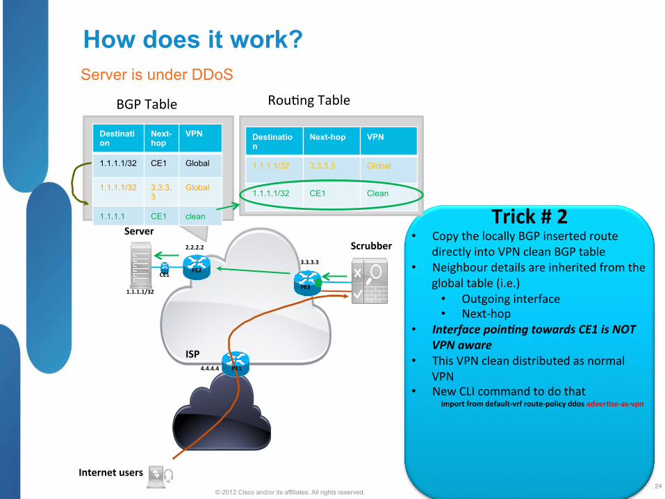
How does it work? Server is under DDoS
24
Internet users
Server Scrubber
ISP
1.1.1.1/32
2.2.2.2
3.3.3.3
4.4.4.4
Destination
Next-hop
VPN
1.1.1.1/32 CE1 Global
1.1.1.1/32 3.3.3.3
Global
1.1.1.1 CE1 clean
BGP Table
PE3
PE2 CE1
Trick # 2 • Copy the locally BGP inserted route
directly into VPN clean BGP table • Neighbour details are inherited from the
global table (i.e.) • Outgoing interface • Next-‐hop
• Interface poin>ng towards CE1 is NOT VPN aware
• This VPN clean distributed as normal VPN
• New CLI command to do that import from default-‐vrf route-‐policy ddos adver<se-‐as-‐vpn
Destination
Next-hop VPN
1.1.1.1/32 3.3.3.3 Global
1.1.1.1/32 CE1 Clean
Rou;ng Table
PE1
© 2012 Cisco and/or its affiliates. All rights reserved. Cisco Public
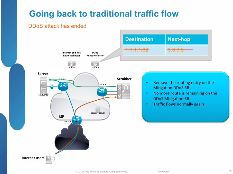
Going back to traditional traffic flow DDoS attack has ended
25
Internet users
• Remove the rou;ng entry on the Mi;ga;on DDoS RR
• No more route is remaining on the DDoS Mi;ga;on RR
• Traffic flows normally again
Server Scrubber
ISP
Internet and VPN Route-‐Reflector
1.1.1.1/32
2.2.2.2
3.3.3.3
4.4.4.4
5.5.5.5
Security server
DDoS Route-‐Reflector
5.5.5.5
Destination Next-hop
1.1.1.1/32 3.3.3.3
PE1

© 2012 Cisco and/or its affiliates. All rights reserved. Cisco Public
Why injecting DDoS in separate BGP instance ?
§ Solution support redirection of BGP less/more specific prefixes or local originated prefixes (static route, redistributed route)
§ Indepenant Inter-Domain control plane and DDoS plane § No need to withdraw and re-signal Inter-Domain prefixes, keep internet
route intacts in control plane. § Easy to troubleshoot
© 2012 Cisco and/or its affiliates. All rights reserved. Cisco Public
Any Ques<ons?
© 2012 Cisco and/or its affiliates. All rights reserved. BRKRST-3371 Cisco Public

© 2012 Cisco and/or its affiliates. All rights reserved. Cisco Public
Backup Slides Technical details

© 2012 Cisco and/or its affiliates. All rights reserved. Cisco Public
Configuration (1)
router bgp 99 instance ddos bgp router-‐id 3.3.3.3 bgp read-‐only bgp install diversion address-‐family ipv4 unicast ! router bgp 99 bgp router-‐id 2.2.2.2 address-‐family ipv4 unicast !
Crea;on of DDoS BGP instance
Allows config of 2th IPv4 or IPv6 instance Suppresses BGP Update Genera;on
Triggers BGP ddos instance to install diversion path to RIB, so that the paths are pushed down to FIB
© 2012 Cisco and/or its affiliates. All rights reserved. Cisco Public
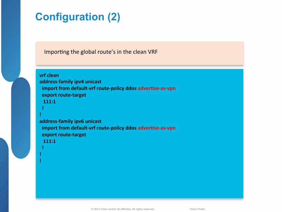
Configuration (2)
vrf clean address-‐family ipv4 unicast import from default-‐vrf route-‐policy ddos adver<se-‐as-‐vpn export route-‐target 111:1 ! ! address-‐family ipv6 unicast import from default-‐vrf route-‐policy ddos adver<se-‐as-‐vpn export route-‐target 111:1 ! ! !
Impor;ng the global route’s in the clean VRF
© 2012 Cisco and/or its affiliates. All rights reserved. Cisco Public
“show” commands
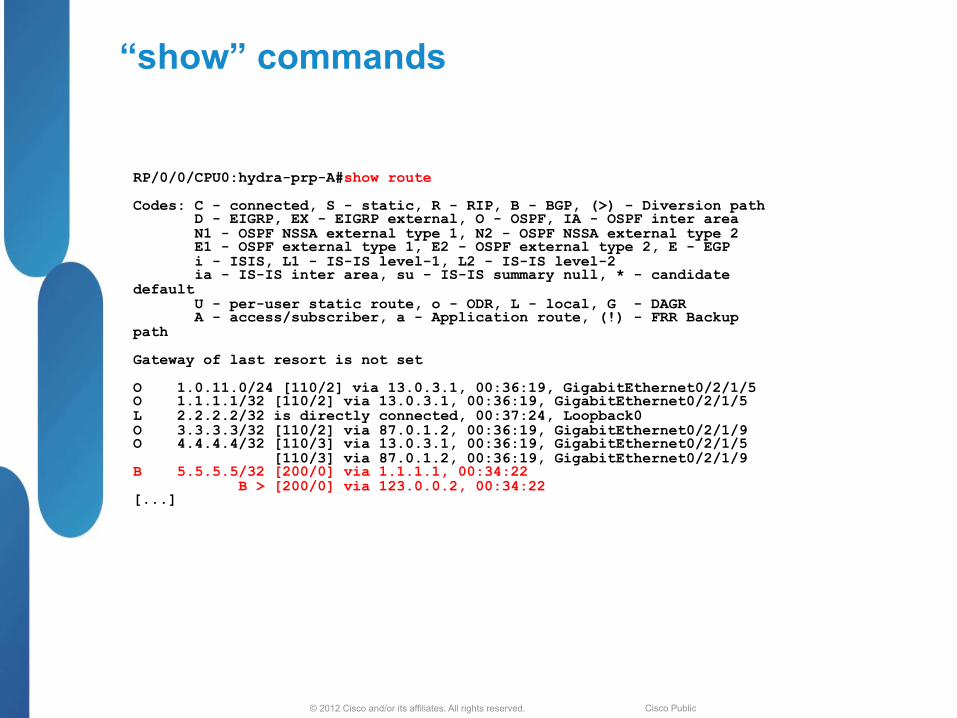
RP/0/0/CPU0:hydra-prp-A#show route Codes: C - connected, S - static, R - RIP, B - BGP, (>) - Diversion path D - EIGRP, EX - EIGRP external, O - OSPF, IA - OSPF inter area N1 - OSPF NSSA external type 1, N2 - OSPF NSSA external type 2 E1 - OSPF external type 1, E2 - OSPF external type 2, E - EGP i - ISIS, L1 - IS-IS level-1, L2 - IS-IS level-2 ia - IS-IS inter area, su - IS-IS summary null, * - candidate default U - per-user static route, o - ODR, L - local, G - DAGR A - access/subscriber, a - Application route, (!) - FRR Backup path Gateway of last resort is not set O 1.0.11.0/24 [110/2] via 13.0.3.1, 00:36:19, GigabitEthernet0/2/1/5 O 1.1.1.1/32 [110/2] via 13.0.3.1, 00:36:19, GigabitEthernet0/2/1/5 L 2.2.2.2/32 is directly connected, 00:37:24, Loopback0 O 3.3.3.3/32 [110/2] via 87.0.1.2, 00:36:19, GigabitEthernet0/2/1/9 O 4.4.4.4/32 [110/3] via 13.0.3.1, 00:36:19, GigabitEthernet0/2/1/5 [110/3] via 87.0.1.2, 00:36:19, GigabitEthernet0/2/1/9 B 5.5.5.5/32 [200/0] via 1.1.1.1, 00:34:22 B > [200/0] via 123.0.0.2, 00:34:22 [...]

© 2012 Cisco and/or its affiliates. All rights reserved. Cisco Public
“show” commands (1)
RP/0/0/CPU0:hydra-prp-A#show route Codes: C - connected, S - static, R - RIP, B - BGP, (>) - Diversion path D - EIGRP, EX - EIGRP external, O - OSPF, IA - OSPF inter area N1 - OSPF NSSA external type 1, N2 - OSPF NSSA external type 2 E1 - OSPF external type 1, E2 - OSPF external type 2, E - EGP i - ISIS, L1 - IS-IS level-1, L2 - IS-IS level-2 ia - IS-IS inter area, su - IS-IS summary null, * - candidate default U - per-user static route, o - ODR, L - local, G - DAGR A - access/subscriber, a - Application route, (!) - FRR Backup path Gateway of last resort is not set O 1.0.11.0/24 [110/2] via 13.0.3.1, 00:36:19, GigabitEthernet0/2/1/5 O 1.1.1.1/32 [110/2] via 13.0.3.1, 00:36:19, GigabitEthernet0/2/1/5 L 2.2.2.2/32 is directly connected, 00:37:24, Loopback0 O 3.3.3.3/32 [110/2] via 87.0.1.2, 00:36:19, GigabitEthernet0/2/1/9 O 4.4.4.4/32 [110/3] via 13.0.3.1, 00:36:19, GigabitEthernet0/2/1/5 [110/3] via 87.0.1.2, 00:36:19, GigabitEthernet0/2/1/9 B 5.5.5.5/32 [200/0] via 1.1.1.1, 00:34:22 B > [200/0] via 123.0.0.2, 00:34:22 [...]
© 2012 Cisco and/or its affiliates. All rights reserved. Cisco Public
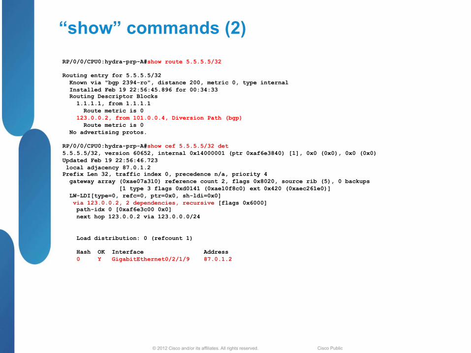
“show” commands (2) RP/0/0/CPU0:hydra-prp-A#show route 5.5.5.5/32 Routing entry for 5.5.5.5/32 Known via "bgp 2394-ro", distance 200, metric 0, type internal Installed Feb 19 22:56:45.896 for 00:34:33 Routing Descriptor Blocks 1.1.1.1, from 1.1.1.1 Route metric is 0 123.0.0.2, from 101.0.0.4, Diversion Path (bgp) Route metric is 0 No advertising protos. RP/0/0/CPU0:hydra-prp-A#show cef 5.5.5.5/32 det 5.5.5.5/32, version 60652, internal 0x14000001 (ptr 0xaf6e3840) [1], 0x0 (0x0), 0x0 (0x0) Updated Feb 19 22:56:46.723 local adjacency 87.0.1.2 Prefix Len 32, traffic index 0, precedence n/a, priority 4 gateway array (0xae07a310) reference count 2, flags 0x8020, source rib (5), 0 backups [1 type 3 flags 0xd0141 (0xae10f8c0) ext 0x420 (0xaec261e0)] LW-LDI[type=0, refc=0, ptr=0x0, sh-ldi=0x0] via 123.0.0.2, 2 dependencies, recursive [flags 0x6000] path-idx 0 [0xaf6e3c00 0x0] next hop 123.0.0.2 via 123.0.0.0/24 Load distribution: 0 (refcount 1) Hash OK Interface Address 0 Y GigabitEthernet0/2/1/9 87.0.1.2
© 2012 Cisco and/or its affiliates. All rights reserved. Cisco Public
“show” commands (3)
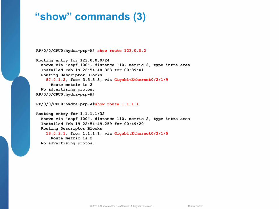
RP/0/0/CPU0:hydra-prp-A# show route 123.0.0.2 Routing entry for 123.0.0.0/24 Known via "ospf 100", distance 110, metric 2, type intra area Installed Feb 19 22:54:48.363 for 00:39:01 Routing Descriptor Blocks 87.0.1.2, from 3.3.3.3, via GigabitEthernet0/2/1/9 Route metric is 2 No advertising protos. RP/0/0/CPU0:hydra-prp-A# RP/0/0/CPU0:hydra-prp-A#show route 1.1.1.1 Routing entry for 1.1.1.1/32 Known via "ospf 100", distance 110, metric 2, type intra area Installed Feb 19 22:54:49.259 for 00:49:20 Routing Descriptor Blocks 13.0.3.1, from 1.1.1.1, via GigabitEthernet0/2/1/5 Route metric is 2 No advertising protos.

© 2012 Cisco and/or its affiliates. All rights reserved. 36