BF-BOSS.pdf
16
Butterfly Valves
-
Upload
jagchavan2011 -
Category
Documents
-
view
250 -
download
15
Transcript of BF-BOSS.pdf
Butterfly Valves

2
GENERAL INDEX
BOSS Ductile Iron Butterfly Valves
Code Number System
1 2 3 4 5 616 L N E
1 Operator CodeLever NoneGear G
2 Pressure16 bar 16
3 Series StyleWafer WLugged LSemi-lugged S
4 Disc/StemNickel Plated N316 Stainless Steel S
5 LinerBUNA BEPDM E
6 Lever ColourBlue NoneYellow Y
Size BSS Code BOSS Code Size BSS Code BOSS Code
50mm 36530402 16LNE 50mm 36530509 16LNB
65mm 36530413 16LNE 65mm 36530520 16LNB
80mm 36530424 16LNE 80mm 36530531 16LNB
100mm 36530435 16LNE 100mm 36530542 16LNB
125mm 36530446 16LNE 125mm 36530553 16LNB
150mm 36530457 16LNE 150mm 36530564 16LNB
200mm 36530468 16LNE 200mm 36530575 16LNB
250mm 36530479 G16LNE 250mm 36530586 G16LNB
300mm 36530490 G16LNE 300mm 36530597 G16LNB
50mm 36530605 16LSE 50mm 36530701 16LSB
65mm 36530616 16LSE 65mm 36530712 16LSB
80mm 36530627 16LSE 80mm 36530723 16LSB
100mm 36530638 16LSE 100mm 36530734 16LSB
125mm 36530649 16LSE 125mm 36530745 16LSB
150mm 36530660 16LSE 150mm 36530756 16LSB
200mm 36530671 16LSE 200mm 36530767 16LSB
250mm 36530682 G16LSE 250mm 36530778 G16LSB
300mm 36530693 G16LSE 300mm 36530789 G16LSB
50mm 36530808 16WNE 50mm 36530904 16WNB
65mm 36530819 16WNE 65mm 36530915 16WNB
80mm 36530830 16WNE 80mm 36530926 16WNB
100mm 36530841 16WNE 100mm 36530937 16WNB
125mm 36530852 16WNE 125mm 36530948 16WNB
150mm 36530863 16WNE 150mm 36530959 16WNB
200mm 36530874 16WNE 200mm 36530970 16WNB
250mm 36530885 G16WNE 250mm 36530981 G16WNB
300mm 36530896 G16WNE 300mm 36530992 G16WNB
50mm 36531009 16WSE 50mm 36531105 16WSB
65mm 36531020 16WSE 65mm 36531116 16WSB
80mm 36531031 16WSE 80mm 36531127 16WSB
100mm 36531042 16WSE 100mm 36531138 16WSB
125mm 36531053 16WSE 125mm 36531149 16WSB
150mm 36531064 16WSE 150mm 36531160 16WSB
200mm 36531075 16WSE 200mm 36531171 16WSB
250mm 36531086 G16WSE 250mm 36531182 G16WSB
300mm 36531097 G16WSE 300mm 36531193 G16WSB
50mm 36530007 16SNE 50mm 36530103 16SNB
65mm 36530018 16SNE 65mm 36530114 16SNB
80mm 36530029 16SNE 80mm 36530125 16SNB
100mm 36530040 16SNE 100mm 36530136 16SNB
125mm 36530051 16SNE 125mm 36530147 16SNB
150mm 36530062 16SNE 150mm 36530158 16SNB
200mm 36530073 16SNE 200mm 36530169 16SNB
50mm 36530210 16SSE 50mm 36530306 16SSB
65mm 36530221 16SSE 65mm 36530317 16SSB
80mm 36530232 16SSE 80mm 36530328 16SSB
100mm 36530243 16SSE 100mm 36530339 16SSB
125mm 36530254 16SSE 125mm 36530350 16SSB
150mm 36530265 16SSE 150mm 36530361 16SSB
200mm 36530276 16SSE 200mm 36530372 16SSB

PN16 Wafer
Ductile Iron Body Extended Neck
Disc NPDI or 316SSLiner NBR or EPDMSize 50mm-200mm lever
250mm-300mm gear
PN16 Semi-lugged
Ductile Iron BodyExtended Neck
Disc NPDI or 316SSLiner NBR or EPDMSize 50mm-200mm lever
250mm-300mm gear
PN16 Lugged
Ductile Iron BodyExtended Neck
Disc NPDI or 316SSLiner NBR or EPDMSize 50mm-200mm lever
250mm-300mm gear
Also available with Yellow Lever for identification of Gas service.
Disc NPDILiner NBRSize 50mm(2in)-200mm(8in)
3
Chemical Resistance Guide
These performance data have been developed from testing, customer fieldreports and/or in-house testing. Properties/applications shown are typical.Your specific application should not be undertaken without independentstudy and evaluation for suitability. While the utmost care has been used incompiling this data, we assume no responsibility for error.
Fluid/Material Disc SeatDuctile 316 NBR EPDM
Acetic Acid (10%) Poor Excellent Very Poor Good
Air Excellent Excellent Excellent Excellent
Ammonia Good Excellent Poor Good(anhydrous liquid)
Ammonia (solution) Good Excellent Good Good
Ammonium Suplhate Poor Good Excellent Excellent
Animal Oil Excellent Excellent Excellent Good
Calcium Carbonate Very Poor Good Excellent Excellent
Carbonic Acid Very Poor Good Good Good
Chlorinated Water – Poor Very Poor Poor
Deionised Water Very Poor Excellent Excellent Excellent
Distilled Water Very Poor Excellent Excellent Excellent
Ethane Good Good Excellent Very Poor
Ethyl Alcohol Good Excellent Good Excellent
Frenon12 Good Excellent Good Excellent
Gasoline Good Excellent Excellent Very Poor(refined/unleaded)
Glycol Excellent Excellent Excellent Excellent
Hydrochloric Acid Very Poor Very Poor Poor Excellent
Hydrogen Gas (cold) Good Excellent Good Good
Lubricating Oil/Motor Oil Excellent Excellent Excellent Very Poor(petroleum based)
Methyl Alcohol Good Excellent Good Excellent
Mineral Oil Good Excellent Excellent Very Poor
Natural Gas Excellent Excellent Good Very Poor
Oils : Diesel Fuel Excellent Excellent Excellent Very Poor(20, 30, 40, 50)
Oils : Fuel Excellent Excellent Good Very Poor(1, 2, 3, 5A, 5B, 6)
Oxygen Gas (cold) Good Excellent Good Good
Petroleum Oil (refined) – – Good Very Poor
Propane Gas Good Excellent Excellent Very Poor
Sea Water Very Poor Good Excellent Excellent
Soybean Oil Poor Excellent Excellent Poor
Sulphuric Acid (7%) Very Poor Good Good Good
Sulphuric Acid (20%) Very Poor Very Poor Very Poor Good
Sulphuric Acid (50%+) Very Poor Very Poor Very Poor Good
Sulphurus Acic Very Poor Good Poor Poor
Steam (100ºC) Excellent Excellent Very Poor Good
Vegetable Oil Poor Excellent Excellent Poor
Vinegar Very Poor Excellent Good Excellent
Water (hot 150ºC) Poor Excellent Very Poor Good
Size (mm) BSS Code BOSS Code50 36531201 16LNBY65 36531212 16LNBY80 36531223 16LNBY100 36531234 16LNBY125 36531245 16LNBY150 36531256 16LNBY200 36531267 16LNBY
4
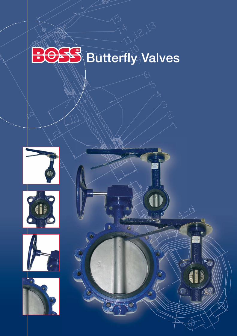
Shaft, ASTM (1):A582 416/A276 316
Short Bushing (2):ASTM B584 C83600
Long Bushing (2):Lubricated Bronze
Seat (1):EPDM/NBRVulcanised
Disc (1):CF8M/A536
Taper Pins (2):A582 416/A276 316
Body (1):A536 65-45-12
Wafer Style
Size 50mm~300mm
‘O’ Ring (1):NBR (BUNA-N)EPDM
BOSS Butterfly Valves PN16

5
BOSS Butterfly Valves – Exploded View
50mm~300mm
Shaft, ASTM (1):A582 416/A276 316
Short Bushing (2):ASTM B584 C83600
‘O’ Ring (1):NBR (BUNA-N)EPDM
Long Bushing (2):Lubricated Bronze
Seat (1):EPDM/NBRVulcanised
Disc (1):CF8M/A536
Taper Pins (2):A582 416/A276 316
Body (1):A536 65-45-12

6
PN16 Butterfly Valves Ductile iron body, extended neck, ISO mounting pad, bondedseatline, lever operated, 50-200mm wafer, lugged or semi-lugged
Size A D1 E B F D L
50 80 52.88 32 161 273 81 43
65 89 64.49 32 175 296 97 46
80 95 78.84 32 181 308 112 46
100 114 104.04 32 200 346 140 52
125 127 123.32 32 213 372 160 56
150 139 155.58 32 226 397 193 56
200 175 202.46 45 260 480 245 60
Material List
The rubber of seat is vulcanised to the body
Item Part Name Specification
1 Body Ductile Iron(A536Gr.65-45-12)
2 Long Bushing ASTM B584 C83600
3 Stem ASTM A582 416/A276 316
4 Seat EPDM/NBR, vulcanised
5 Disc ASTM A351 CF8M/A536 65-45-12
6 Taper Pin ASTM A582 416/A276 316
7 Nameplate Aluminium
8 Rivet Aluminium
9 Short Bushing ASTM B584 C83600
10 ‘O’ Ring NBR
11 Bolts Steel
12 Nuts Steel
13 Spacer AISI1566
14 Latchplate Steel
15 Handle Ductile Iron
Dimensions (mm)
Flange Bolting Data/Weights
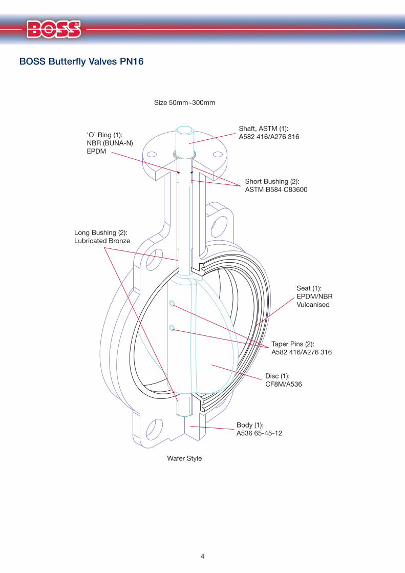
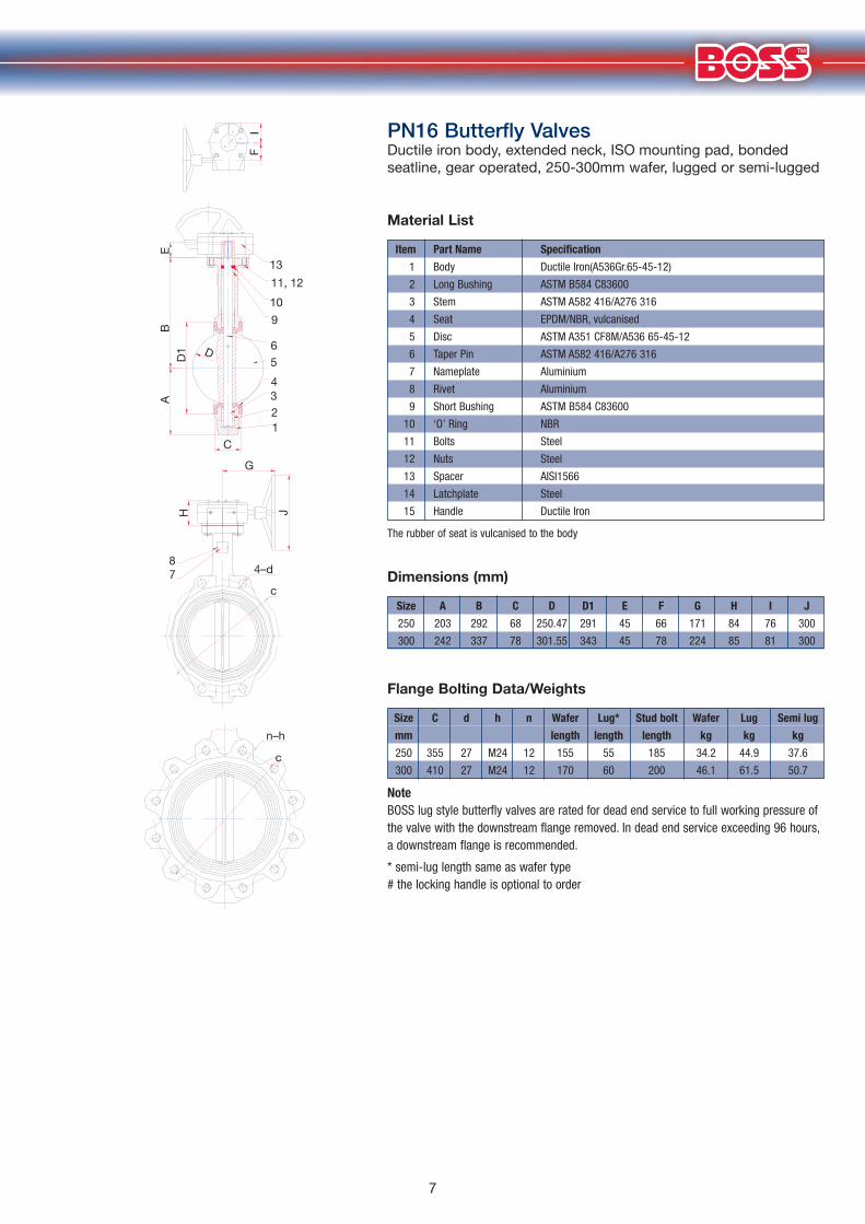
NoteBOSS lug style butterfly valves are rated for dead end service to full working pressure ofthe valve with the downstream flange removed. In dead end service exceeding 96 hours,a downstream flange is recommended.
* semi-lug length same as wafer type # the locking handle is optional to order
Size C d h n Wafer Lug* Stud bolt Wafer Lug Semi lug
mm length length length kg kg kg
50 M16 19 125 4 105 35 125 3.4 4.6 3.9
65 M16 19 145 4 108 38 130 4.1 5.9 4.7
80 M16 19 160 8 108 38 130 4.5 6.1 5.1
100 M16 19 180 8 115 40 135 6.3 10.0 6.9
125 M16 19 210 8 115 40 140 8.8 12.6 9.7
150 M20 23 240 8 120 40 150 10.4 16.1 11.0
200 M20 23 295 12 140 50 160 17.8 25.0 19.5
4
OPEN
56
78
34
21
65
ESOL
C
3 21
14
A
F
E
D1
BD
A
L
151411, 12 ,13109
654321
87 4–d
c
n–hc
15
7
PN16 Butterfly Valves Ductile iron body, extended neck, ISO mounting pad, bondedseatline, gear operated, 250-300mm wafer, lugged or semi-lugged
Size A B C D D1 E F G H I J
250 203 292 68 250.47 291 45 66 171 84 76 300
300 242 337 78 301.55 343 45 78 224 85 81 300
Material List
The rubber of seat is vulcanised to the body
Item Part Name Specification
1 Body Ductile Iron(A536Gr.65-45-12)
2 Long Bushing ASTM B584 C83600
3 Stem ASTM A582 416/A276 316
4 Seat EPDM/NBR, vulcanised
5 Disc ASTM A351 CF8M/A536 65-45-12
6 Taper Pin ASTM A582 416/A276 316
7 Nameplate Aluminium
8 Rivet Aluminium
9 Short Bushing ASTM B584 C83600
10 ‘O’ Ring NBR
11 Bolts Steel
12 Nuts Steel
13 Spacer AISI1566
14 Latchplate Steel
15 Handle Ductile Iron
Dimensions (mm)
Flange Bolting Data/Weights
NoteBOSS lug style butterfly valves are rated for dead end service to full working pressure ofthe valve with the downstream flange removed. In dead end service exceeding 96 hours,a downstream flange is recommended.
* semi-lug length same as wafer type # the locking handle is optional to order
Size C d h n Wafer Lug* Stud bolt Wafer Lug Semi lug
mm length length length kg kg kg
250 355 27 M24 12 155 55 185 34.2 44.9 37.6
300 410 27 M24 12 170 60 200 46.1 61.5 50.7
I F
13
11, 12
10
9
B
E
D
A
J H
D1
C
G
7 c
4–d
n–h
c
8
6 5
4 3 2 1

8
Resilient Liner Materials
EPDMEPDM is a terpolymer elastomer made from ethylene-propylene diene monomer. EPDM has good abrasion andtear resistance and offers excellent chemical resistance to a variety of acids and alkalis. It is susceptible to attackby oil and is not recommended for applications involving petroleum oils, strong acids, or strong alkalis. It shouldnot be used for compressed air lines. It has exceptionally good weather aging and ozone resistance and hasfairly good resistance to ketones and alcohols.
BUNA-N (Nitrile) (NBR)BUNA-N is a general-purpose oil resistant polymer known as Nitrile rubber. It is a copolymer of butadiene andacrylonitrile. It has good resistance to hydraulic fluid, oil, water, and solvents. It shows good tensile strength andabrasion resistance while displaying good compression set. It is not recommended for highly polar solvents suchas acetone and methyl ethyl ketone nor in chlorinated hydrocarbons, ozone or nitro hydrocarbons.
Liner Material Temperature Range
BOSS designs utilise proprietary compound formulas for each elastomer. They provide the right combinationof seat compression, abrasion and chemical resistance to match a broad range of applications.* Continuous service temperature range 0 to +100ºC
NoteElastomeric seat materials are not suitable for steam service
Specifications
BOSS Butterfly valves are designed and manufactured to provide maximum performance on recommendedservice applications at the lowest possible initial and life cycle cost. They meet or exceed the following standardsdeveloped through research, laboratory tests and years of experience.
Butterfly Valves• British Standard BS5155 (Short Pattern)• Manufacturers Standardization Society MSS SP-25
of the Valve and Fitting Industry MSS SP-67
WRAS ApprovalAll EPDM seat BOSS butterfly valves have manufacturers WRAS Approval for sizes2" (50mm) through to 12" (300mm) inclusive.
WRAS nameplates are available (on request) and manufacturers Certificate of Conformity.
Liner Material TemperatureEPDM -20 to +120ºC*BUNA-N (Nitrile) 0 to +70ºC

9
Bare Stem Dimensional Data for Actuation
Dimensions 50mm-300mm D2
LL1
h
d0
D1
D
H
4–d45º
Actuation
Actuation of butterfly valves is available. Please contact your local BSS branch for full details.
The butterfly valve range forms part of a wider range of BOSS brandedproducts available exclusively from BSS. See our website for full details:
www.bssuk.co.uk
Size D D1 D2 d0 d1 H L L1 h d
DN in
50 2 65 50 35 12.1 12.6 9 32 12 4 7
65 21⁄2 65 50 35 12.1 12.6 9 32 14 4 7
80 3 65 50 35 12.1 12.6 9 32 13 4 7
100 4 90 70 55 14.1 15.77 11 32 16 4 10
125 5 90 70 55 18.1 18.92 14 32 14 4 10
150 6 90 70 55 18.1 18.92 14 32 14 4 10
200 8 125 102 70 22.1 22.1 17 45 14 4 12
250 10 125 102 70 28.2 28.45 22 45 16 4 12
300 12 150 125 85 28.2 31.6 22 45 20 4 14
10
Flow Data
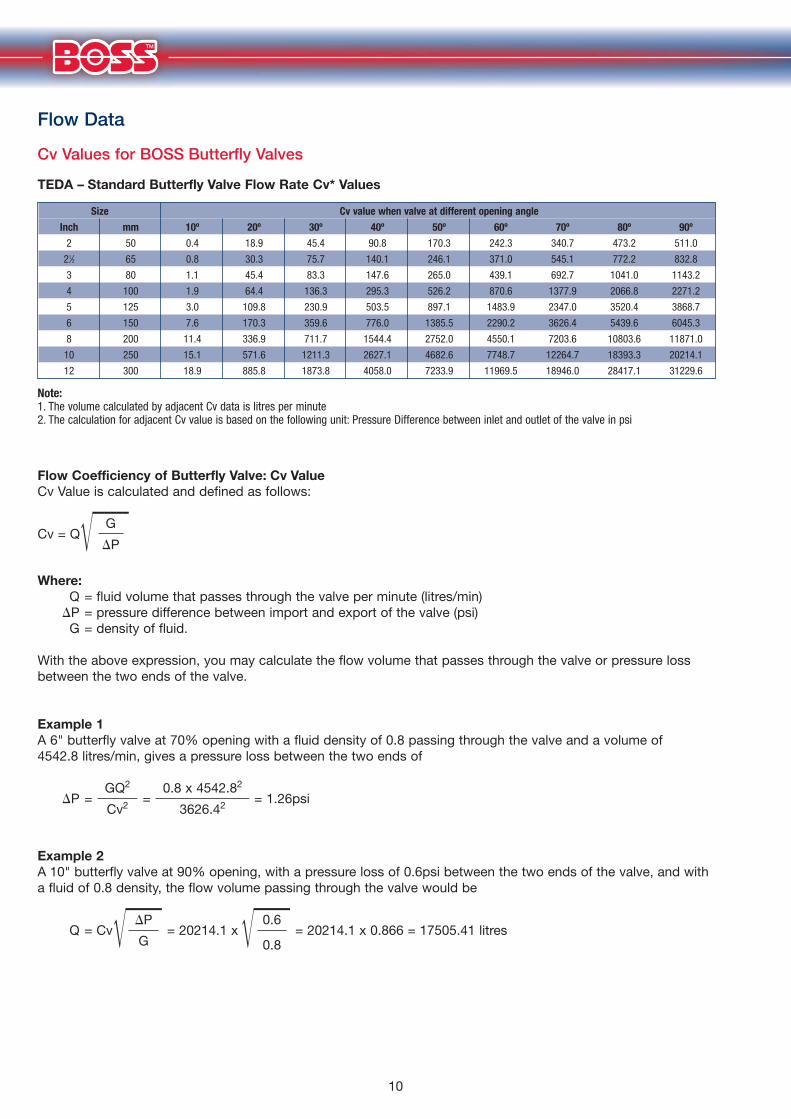
Cv Values for BOSS Butterfly Valves
TEDA – Standard Butterfly Valve Flow Rate Cv* Values
Size Cv value when valve at different opening angle
Inch mm 10º 20º 30º 40º 50º 60º 70º 80º 90º
2 50 0.4 18.9 45.4 90.8 170.3 242.3 340.7 473.2 511.0
21⁄2 65 0.8 30.3 75.7 140.1 246.1 371.0 545.1 772.2 832.8
3 80 1.1 45.4 83.3 147.6 265.0 439.1 692.7 1041.0 1143.2
4 100 1.9 64.4 136.3 295.3 526.2 870.6 1377.9 2066.8 2271.2
5 125 3.0 109.8 230.9 503.5 897.1 1483.9 2347.0 3520.4 3868.7
6 150 7.6 170.3 359.6 776.0 1385.5 2290.2 3626.4 5439.6 6045.3
8 200 11.4 336.9 711.7 1544.4 2752.0 4550.1 7203.6 10803.6 11871.0
10 250 15.1 571.6 1211.3 2627.1 4682.6 7748.7 12264.7 18393.3 20214.1
12 300 18.9 885.8 1873.8 4058.0 7233.9 11969.5 18946.0 28417.1 31229.6
Flow Coefficiency of Butterfly Valve: Cv ValueCv Value is calculated and defined as follows:
�������GCv = Q
�P
Where:Q = fluid volume that passes through the valve per minute (litres/min)
�P = pressure difference between import and export of the valve (psi) G = density of fluid.
With the above expression, you may calculate the flow volume that passes through the valve or pressure lossbetween the two ends of the valve.
Example 1A 6" butterfly valve at 70% opening with a fluid density of 0.8 passing through the valve and a volume of 4542.8 litres/min, gives a pressure loss between the two ends of
GQ2 0.8 x 4542.82
�P = = = 1.26psi Cv2 3626.42
Example 2A 10" butterfly valve at 90% opening, with a pressure loss of 0.6psi between the two ends of the valve, and witha fluid of 0.8 density, the flow volume passing through the valve would be
������� ��������P 0.6Q = Cv = 20214.1 x = 20214.1 x 0.866 = 17505.41 litres
G 0.8
Note:1. The volume calculated by adjacent Cv data is litres per minute2. The calculation for adjacent Cv value is based on the following unit: Pressure Difference between inlet and outlet of the valve in psi
11
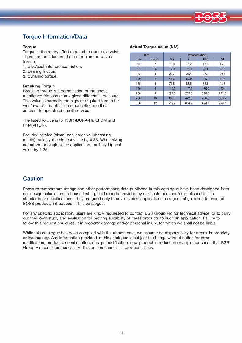
Torque Information/Data
TorqueTorque is the rotary effort required to operate a valve.There are three factors that determine the valvestorque:1. disc/seat interference friction,2. bearing friction,3. dynamic torque.
Breaking TorqueBreaking torque is a combination of the abovementioned frictions at any given differential pressure.This value is normally the highest required torque forÔwet ’ (water and other non-lubricating media atambient temperature) on/off service.
The listed torque is for NBR (BUNA-N), EPDM andFKM(VITON).
For ‘dry’ service (clean, non-abrasive lubricatingmedia) multiply the highest value by 0.85. When sizingactuators for single value application, multiply highestvalue by 1.25
Actual Torque Value (NM)
Size Pressure (bar)mm inches 3.5 7 10.5 14
50 2 13.0 13.2 13.6 15.3
65 21⁄2 17.9 18.9 20.1 21.5
80 3 22.7 26.4 27.3 29.4
100 4 46.3 50.9 55.4 57.6
125 5 76.8 83.6 88.1 93.8
150 6 110.5 117.5 130.0 140.1
200 8 224.6 235.0 248.6 271.2
250 10 365.3 422.6 486.0 508.5
300 12 512.2 604.9 694.7 779.7
Caution
Pressure-temperature ratings and other performance data published in this catalogue have been developed fromour design calculation, in-house testing, field reports provided by our customers and/or published officialstandards or specifications. They are good only to cover typical applications as a general guideline to users ofBOSS products introduced in this catalogue.
For any specific application, users are kindly requested to contact BSS Group Plc for technical advice, or to carryout their own study and evaluation for proving suitability of these products to such an application. Failure tofollow this request could result in property damage and/or personal injury, for which we shall not be liable.
While this catalogue has been compiled with the utmost care, we assume no responsibility for errors, improprietyor inadequacy. Any information provided in this catalogue is subject to change without notice for errorrectification, product discontinuation, design modification, new product introduction or any other cause that BSSGroup Plc considers necessary. This edition cancels all previous issues.

12
Storage, Handling and Installation Guide
Storage and HandlingStore valves in a dry, clean and corrosion-free environment with nodirect exposure to the sun, leaving valves 10° open for preventionof permanent distortion of the resilient seat. Care should beexercised while storing valves. Avoid dropping valves on a hardsurface or stacking too high to prevent damage to valve or injuryto the handler.
Installation on Pipeline1. Mount valve onto flanges only after flanges have been welded
to pipes and cooled down to room temperature to preventdamage to resilient seat.
2. Inspect flange surface finish to assure that it is smooth and freeof damage or deformation. Remove rust, welding splatters andany foreign objects from flange finish and bore that may affectsealing performance and operation.
3. For trouble-free operation it is essential to center and align bothupstream and downstream flanges as shown in Fig 1.
4. To begin valve mounting, set jack bolts under the piping for flatsupport at the same height, and adjust the flange-to-flangedistance so the it is roughly 1⁄4" (6mm) clearance on both sidesof valve body.
5. Set two alignment bolts into lower mounting guides/lug of valveand install valve being careful not to force to prevent damage toresilient seat (Fig 2).
6. Insert the next set of bolts in the upper mounting guides/lugsand center valve within flanges. Before flange bolts are tightenedcarefully open to assure unobstructed disc movement.Interference of the disc may be the result of heavy wall pipe,plastic lined pipe, cast flanges or when bolted directly to areducing flange and or another valve. It may be necessary totaper bore the pipe to allow free disc movement or you mayneed to install a spool piece/spacer between the two valves.Remove jack bolts and set all bolts and tighten alternatingdiagonally until the flange contacts the valve body (Figs 3 and 4).
Valve Operation1. Valve operation should be limited to lever, gears or actuation.
The use of cheater bar may result in the malfunction of thevalve and operator.
2. Valves should be fully opened before loop test of the pipingsystem with higher than normal pressure. The use of closedvalve in place of a blind flange is not recommended.
3. Before dismantling valves from piping system, take thefollowing precautions:a. do not loosen bolts while under pressure,b. do relieve line pressure,c. completely drain piping system.
Note1. Use piping flanges conforming to PN16.2. Mechanical or rubber faced flanges are not recommended.3. NBR and EPDM are not recommended for steam service.
Fig.1
Fig.3Fig.2
Fig.4

13
Flange Bolt Data
Bolt/Stud Hex Head Bolt Hex Head Stud Size Diameter Bolt Length A Bolt Length B Length Cmm mm No No mm mm mm
50 M16 4 8 105 35 125
65 M16 4 8 108 38 130
80 M16 8 16 108 38 130
100 M16 8 8 115 40 135
125 M16 8 16 115 40 140
150 M20 8 16 120 40 145
200 M20 12 24 140 50 165
250 M24 12 24 155 55 185
300 M24 12 24 170 60 200
NoteUse pipe flanges conforming to PN16.Steel, cast iron, bronze and plastic may beused. The use of additional flange gasketsare not required. Threads on bolts, studsand nuts shall be in accordance with theUnified Course Thread Series (UNC), ClassA and B (ANSI B-1.1).
Wafer Style
Bolt
Lug Style
Hex Head Bolt
Lug/Wafer Style
Stud
A B C
14
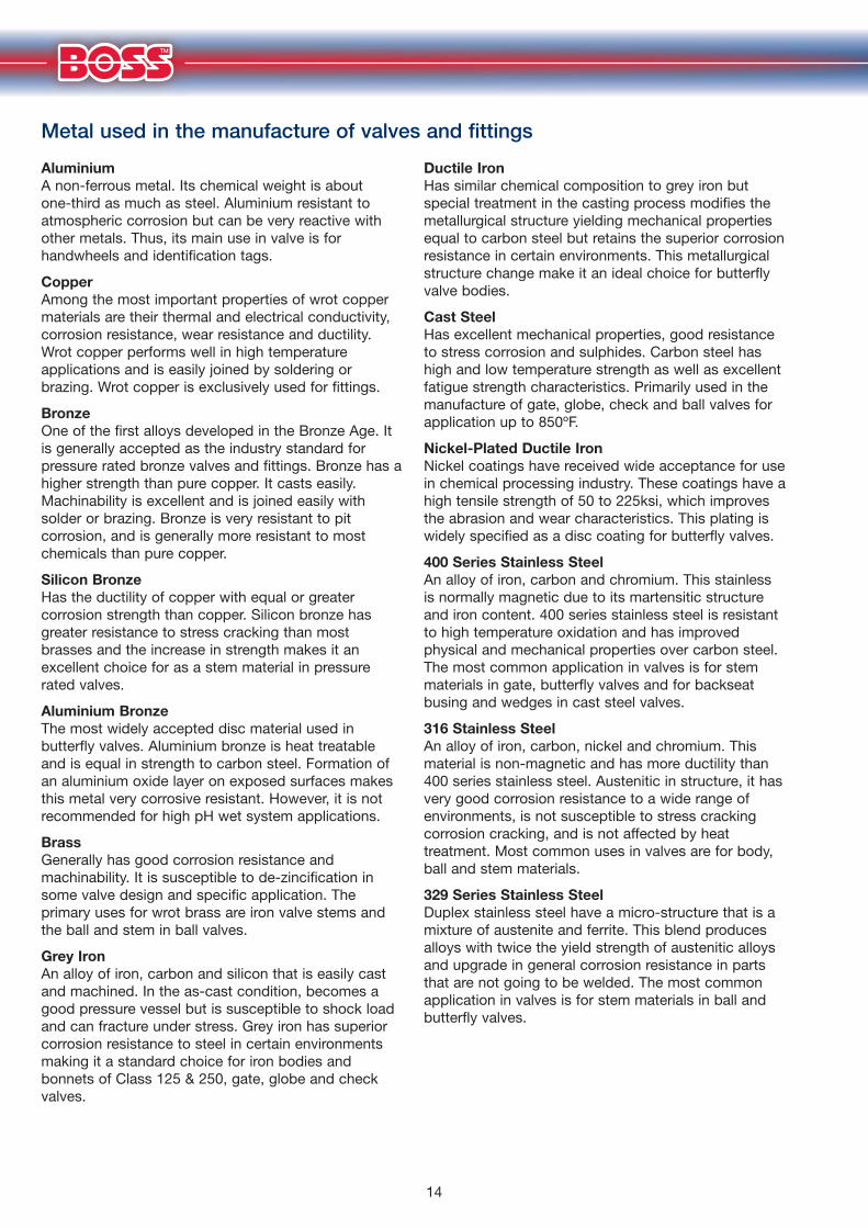
AluminiumA non-ferrous metal. Its chemical weight is aboutone-third as much as steel. Aluminium resistant toatmospheric corrosion but can be very reactive withother metals. Thus, its main use in valve is forhandwheels and identification tags.
CopperAmong the most important properties of wrot coppermaterials are their thermal and electrical conductivity,corrosion resistance, wear resistance and ductility.Wrot copper performs well in high temperatureapplications and is easily joined by soldering orbrazing. Wrot copper is exclusively used for fittings.
BronzeOne of the first alloys developed in the Bronze Age. Itis generally accepted as the industry standard forpressure rated bronze valves and fittings. Bronze has ahigher strength than pure copper. It casts easily.Machinability is excellent and is joined easily withsolder or brazing. Bronze is very resistant to pitcorrosion, and is generally more resistant to mostchemicals than pure copper.
Silicon BronzeHas the ductility of copper with equal or greatercorrosion strength than copper. Silicon bronze hasgreater resistance to stress cracking than mostbrasses and the increase in strength makes it anexcellent choice for as a stem material in pressurerated valves.
Aluminium BronzeThe most widely accepted disc material used inbutterfly valves. Aluminium bronze is heat treatableand is equal in strength to carbon steel. Formation ofan aluminium oxide layer on exposed surfaces makesthis metal very corrosive resistant. However, it is notrecommended for high pH wet system applications.
BrassGenerally has good corrosion resistance andmachinability. It is susceptible to de-zincification insome valve design and specific application. Theprimary uses for wrot brass are iron valve stems andthe ball and stem in ball valves.
Grey IronAn alloy of iron, carbon and silicon that is easily castand machined. In the as-cast condition, becomes agood pressure vessel but is susceptible to shock loadand can fracture under stress. Grey iron has superiorcorrosion resistance to steel in certain environmentsmaking it a standard choice for iron bodies andbonnets of Class 125 & 250, gate, globe and checkvalves.
Ductile IronHas similar chemical composition to grey iron butspecial treatment in the casting process modifies themetallurgical structure yielding mechanical propertiesequal to carbon steel but retains the superior corrosionresistance in certain environments. This metallurgicalstructure change make it an ideal choice for butterflyvalve bodies.
Cast SteelHas excellent mechanical properties, good resistanceto stress corrosion and sulphides. Carbon steel hashigh and low temperature strength as well as excellentfatigue strength characteristics. Primarily used in themanufacture of gate, globe, check and ball valves forapplication up to 850ºF.
Nickel-Plated Ductile IronNickel coatings have received wide acceptance for usein chemical processing industry. These coatings have ahigh tensile strength of 50 to 225ksi, which improvesthe abrasion and wear characteristics. This plating iswidely specified as a disc coating for butterfly valves.
400 Series Stainless SteelAn alloy of iron, carbon and chromium. This stainlessis normally magnetic due to its martensitic structureand iron content. 400 series stainless steel is resistantto high temperature oxidation and has improvedphysical and mechanical properties over carbon steel.The most common application in valves is for stemmaterials in gate, butterfly valves and for backseatbusing and wedges in cast steel valves.
316 Stainless SteelAn alloy of iron, carbon, nickel and chromium. Thismaterial is non-magnetic and has more ductility than400 series stainless steel. Austenitic in structure, it hasvery good corrosion resistance to a wide range ofenvironments, is not susceptible to stress crackingcorrosion cracking, and is not affected by heattreatment. Most common uses in valves are for body,ball and stem materials.
329 Series Stainless SteelDuplex stainless steel have a micro-structure that is amixture of austenite and ferrite. This blend producesalloys with twice the yield strength of austenitic alloysand upgrade in general corrosion resistance in partsthat are not going to be welded. The most commonapplication in valves is for stem materials in ball andbutterfly valves.
Metal used in the manufacture of valves and fittings
15
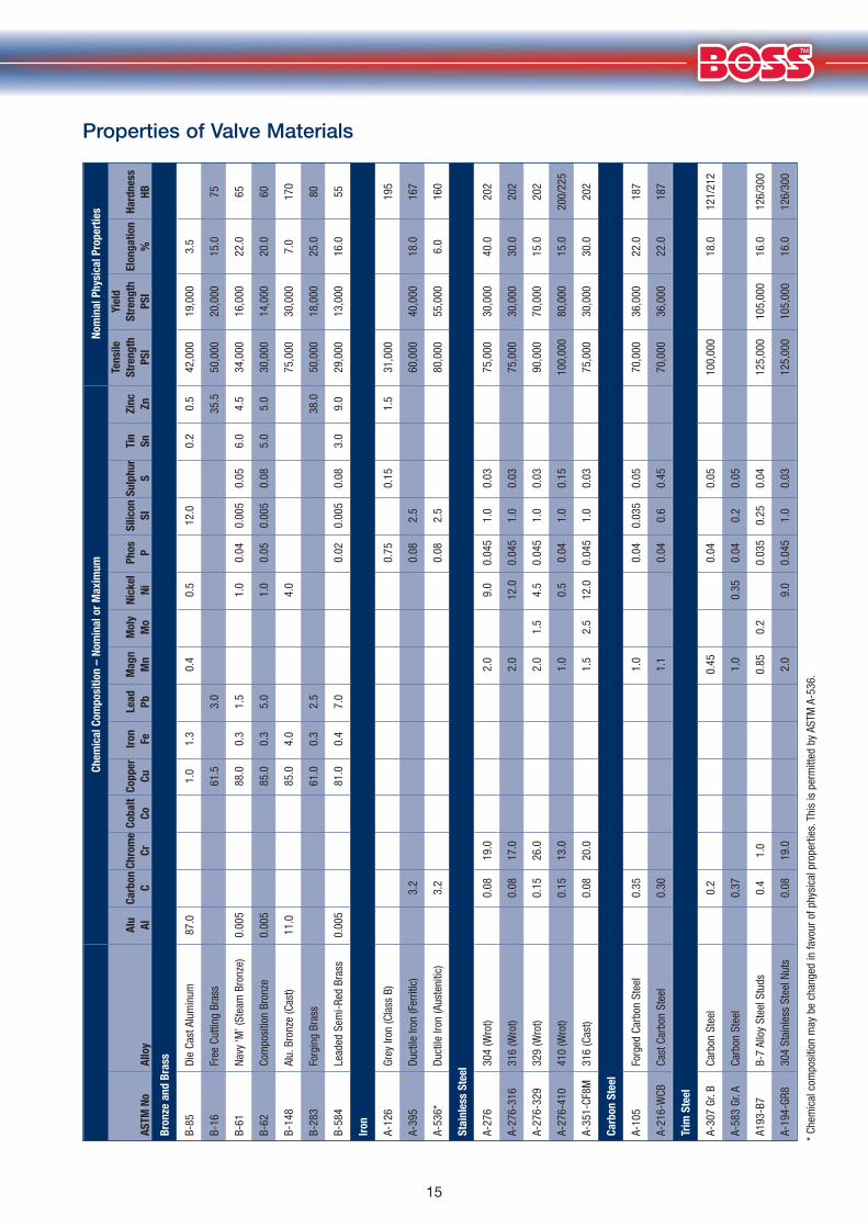
Properties of Valve Materials
* Ch
emic
al c
ompo
sitio
n m
ay b
e ch
ange
d in
favo
ur o
f phy
sica
l pro
perti
es.T
his
is p
erm
itted
by
ASTM
A-5
36.
Chem
ical
Com
posi
tion
– No
min
al o
r M
axim
umNo
min
al P
hysi
cal P
rope
rtie
s
Tens
ileYi
eld
Alu
Carb
onCh
rom
eCo
balt
Copp
erIro
nLe
adM
agn
Mol
yNi
ckel
Phos
Silic
onSu
lphu
rTi
nZi
ncSt
reng
thSt
reng
th
Elon
gatio
nHa
rdne
ssAS
TMNo
Allo
yAl
CCr
CoCu
FePb
Mn
Mo
NiP
SIS
SnZn
PSI
PSI
%HB
Bron
ze a
nd B
rass
B-85
Die
Cast
Alu
min
um87
.01.
01.
30.
40.
512
.00.
20.
542
,000
19,0
003.
5
B-16
Free
Cut
ting
Bras
s61
.53.
035
.550
,000
20,0
0015
.075
B-61
Na
vy ‘M
’ (St
eam
Bro
nze)
0.00
588
.00.
31.
51.
00.
040.
005
0.05
6.0
4.5
34,0
0016
,000
22.0
65
B-62
Com
posi
tion
Bron
ze0.
005
85.0
0.3
5.0
1.0
0.05
0.00
50.
085.
05.
030
,000
14,0
0020
.060
B-14
8Al
u.Br
onze
(Cas
t)11
.085
.04.
04.
075
,000
30,0
007.
017
0
B-28
3Fo
rgin
g Br
ass
61.0
0.3
2.5
38.0
50,0
0018
,000
25.0
80
B-58
4Le
aded
Sem
i-Red
Bra
ss0.
005
81.0
0.4
7.0
0.02
0.00
50.
083.
09.
029
,000
13,0
0016
.055
Iron
A-12
6Gr
ey Ir
on (C
lass
B)
0.75
0.15
1.5
31,0
0019
5
A-39
5Du
ctile
Iron
(Fer
ritic
)3.
20.
082.
560
,000
40,0
0018
.016
7
A-53
6*Du
ctile
Iron
(Aus
teni
tic)
3.2
0.08
2.5
80,0
0055
,000
6.0
160
Stai
nles
s St
eel
A-27
6 30
4 (W
rot)
0.08
19.0
2.0
9.0
0.04
51.
00.
0375
,000
30,0
0040
.020
2
A-27
6-31
6 31
6 (W
rot)
0.08
17.0
2.0
12.0
0.04
51.
00.
0375
,000
30,0
0030
.020
2
A-27
6-32
9 32
9 (W
rot)
0.15
26.0
2.0
1.5
4.5
0.04
51.
00.
0390
,000
70,0
0015
.020
2
A-27
6-41
0 41
0 (W
rot)
0.15
13.0
1.0
0.5
0.04
1.0
0.15
100,
000
80,0
0015
.020
0/22
5
A-35
1-CF
8M31
6 (C
ast)
0.08
20.0
1.5
2.5
12.0
0.04
51.
00.
0375
,000
30,0
0030
.020
2
Carb
on S
teel
A-10
5Fo
rged
Car
bon
Stee
l0.
351.
00.
040.
035
0.05
70,0
0036
,000
22.0
187
A-21
6-W
CBCa
st C
arbo
n St
eel
0.30
1.1
0.04
0.6
0.45
70,0
0036
,000
22.0
187
Trim
Ste
el
A-30
7 Gr
.BCa
rbon
Ste
el0.
20.
450.
040.
0510
0,00
018
.012
1/21
2
A-58
3 Gr
.ACa
rbon
Ste
el0.
371.
00.
350.
040.
20.
05
A193
-B7
B-7
Allo
y St
eel S
tuds
0.4
1.0
0.85
0.2
0.03
50.
250.
0412
5,00
010
5,00
016
.012
6/30
0
A-19
4-GR
830
4 St
ainl
ess
Stee
l Nut
s0.
0819
.02.
09.
00.
045
1.0
0.03
125,
000
105,
000
16.0
126/
300
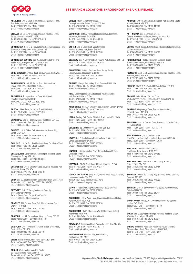
BSS BRANCH LOCATIONS THROUGHOUT THE UK & IRELAND
Pipeline & Heating Solutions
ABERDEEN Unit 5, South Middleton Base, Greenwell Road,East Tullos, Aberdeen AB12 3AXTel: 01224 292929 Fax: 01224 898252Email: [email protected]
BELFAST 36-38 Duncrue Road, Duncrue Industrial Estate,Belfast, Northern Ireland BT3 9BPTel: 028 9078 4000 Fax: 028 9078 4010Email: [email protected]
BIRMINGHAM Units 2 & 4 Crystal Drive, Sandwell Business Park,Smethwick, Warley, West Midlands B66 1QGTel: 0121 552 6000 Fax: 0121 552 5363Email: [email protected]
BIRMINGHAM CENTRAL Unit 49, Gravelly Industrial Park,Tyburn Road, Erdington, Birmingham B24 8TGTel: 0121 322 0370 Fax: 0121 322 2296Email: [email protected]
BOREHAMWOOD Chester Road, Borehamwood, Herts WD6 1LTTel: 020 8327 4100 Fax: 020 8327 4101Email: [email protected]
BOURNEMOUTH Unit 3B, Broom Road Business Park,Broom Road, Poole, Dorset BH12 4PATel: 01202 711300 Fax: 01202 711301Email: [email protected]
BRENTFORD Transport Avenue, Great West Road,Brentford, Middlesex TW8 9HFTel: 020 8232 2727 Fax: 020 8232 2730Email: [email protected]
BRISTOL Albert Road, St Philips, Bristol BS2 0BSTel: 0117 972 7900 Fax: 0117 972 7901Email: [email protected]
CAMBRIDGE Unit 3, Rosemary Lane, Cambridge CB1 3LQTel: 01223 404040 Fax: 01223 240420Email: [email protected]
CARDIFF Unit 4, Trident Park, Glass Avenue, Ocean Way,Cardiff CF24 5ENTel: 029 2043 2400 Fax: 029 2049 7815Email: [email protected]
CARLISLE Unit 2A, Port Road Business Park, Carlisle CA2 7AJTel: 01228 517600 Fax: 01228 598090Email: [email protected]
CHESSINGTON Oakcroft Road, Chessington Industrial Estate,Chessington, Surrey KT9 1RHTel: 020 8974 3800 Fax: 020 8391 5241Email: [email protected]
COLCHESTER Unit 6, Smeaton Close, Severalls Industrial ParkColchester, Essex CO4 9QYTel: 01206 754720 Fax: 01206 752649Email: [email protected]
CORK Unit 20, South Link Park, Ballycurren Road, Grange, CorkTel: 00353 214 321588 Fax: 00353 214 321595Email: [email protected]
COVENTRY Unit 17, Torrington Avenue, Coventry,West Midlands CV4 9HNTel: 024 7669 4744 Fax: 024 7647 0574Email: [email protected]
CRAWLEY 12A Denvale Trade Park, Haslett Avenue East,Crawley RH10 1SSTel: 01293 610170 Fax: 01293 523388Email: [email protected]
CROYDON Unit 34, Factory Lane, Croydon, Surrey CR0 3RLTel: 020 8662 2300 Fax: 020 8681 6142Email: [email protected]
DARTFORD Unit 11 Orbital One, Green Street, Green Road,Dartford, Kent DA1 1QGTel: 01322 289039 Fax: 01322 289149Email: [email protected]
DERBY Riverside Road, Pride Park, Derby DE24 8HHTel: 01332 685600 Fax: 01332 685601Email: [email protected]
DUBLIN White Heather Industrial Estate,301 South Circular Road, Dublin 8Tel: 00353 14 165100 Fax: 00353 14 165165Email: [email protected]
DUNDEE Unit 1-3, Rutherford Road,Dryburgh Industrial Estate, Dundee DD2 3XHTel: 01382 823700 Fax: 01382 826921Email: [email protected]
EDINBURGH Unit 2A, Pentland Industrial Estate, Loanhead,Midlothian, Edinburgh EH20 9QHTel: 0131 440 5900 Fax: 0131 440 3761Email: [email protected]
EXETER Unit 6, Otter Court, Manaton Close,Matford Business Park, Exeter EX2 8PFTel: 01392 457500 Fax: 01392 425976Email: [email protected]
GLASGOW Unit A, Vermont Street, Kinning Park, Glasgow G41 1LUTel: 0141 418 4444 Fax: 0141 429 2638Email: [email protected]
GLOUCESTER Unit C1, Eastbrook Road Trading Estate,Eastern Avenue, Gloucester, GL4 3DBTel: 01452 872200 Fax: 01452 309899Email: [email protected]
GRIMSBY Europa Park, Gilbey Road, Grimsby DN31 2FDTel: 01472 265100 Fax: 01472 241638Email: [email protected]
HULL Copenhagen Road, Sutton Fields Industrial Estate,Hull, East Yorkshire HU7 0YHTel: 01482 625800 Fax: 01482 838870Email: [email protected]
KINGS CROSS Unit 2, 1 Brewery Road, Islington, London N7 9QJTel: 020 7619 7600 Fax: 020 7700 2482Email: [email protected]
LEEDS Turnkey Park Estate, Whitehall Road, Leeds LS12 6ADTel: 0113 203 2203 Fax: 0113 279 8662Email: [email protected]
LEICESTER 66 Cobden Street, Leicester LE1 2LBTel: 0116 242 7800 Fax: 0116 253 2456Email: [email protected]
LEWES Unit 5, South Downs Business Park, Brooks Road,Lewes, East Sussex BN7 2FBTel: 01273 485000 Fax: 01273 480709Email: [email protected]
LINCOLN Units 3/4, Crofton Drive, Allenby Industrial Estate,Lincoln LN3 4NRTel: 01522 565700 Fax: 01522 512678Email: [email protected]
LIVERPOOL 82/94 Great Howard Street, Liverpool L3 7AXTel: 0151 482 2500 Fax: 0151 207 2317Email: [email protected]
LONDON DOCKLANDS Units 6 & 7, Thomas Road Industrial Estate,Limehouse, London E14 7BNTel: 020 7531 3900 Fax: 020 7537 4849Email: [email protected]
LUTON 1 Trojan Court, Laporte Way, Luton, Beds LU4 8RJTel: 01582 875600 Fax: 01582 452050Email: [email protected]
MAIDSTONE Unit 5, Wood Close, Quarry Wood Industrial Estate,Aylesford, Kent ME20 7UBTel: 01622 713600 Fax: 01622 713616Email: [email protected]
MANCHESTER Unit 1, Columbus Way, Off Broadway, Salford,Manchester M50 1UUTel: 0161 888 6464 Fax: 0161 888 6465Email: [email protected]
NEWCASTLE Sanderson Street, Newcastle-upon-Tyne NE4 7PJTel: 0191 256 5100 Fax: 0191 272 3115Email: [email protected]
NORTHAMPTON Riverside Way, Bedford Road,Northampton NN1 5NXTel: 01604 251400 Fax: 01604 620588Email: [email protected]
NORWICH Unit 13, Alston Road, Hellesdon Park Industrial Estate,Norwich, Norfolk NR6 5DSTel: 01603 253200 Fax: 01603 418839Email: [email protected]
NOTTINGHAM Unit 3, Longwall Avenue,Queens Drive Industrial Estate, Nottingham NG2 1NATel: 0115 943 5900 Fax: 0115 986 1099Email: [email protected]
OXFORD Unit C Taurus, Peterley Road, Horspath Industrial Estate,Cowley, Oxford OX4 2TZTel: 01865 398870 Fax: 01865 777552Email: [email protected]
PETERBOROUGH Unit 2a, Centurion Business Centre,Sturrock Way, Bretton, Peterborough PE3 8YBTel: 01733 336000 Fax: 01733 265790Email: [email protected]
PLYMOUTH Block G, St. Modwen Road, Parkway Industrial Estate,Plymouth, Devon PL6 8LHTel: 01752 675300 Fax: 01752 220063Email: [email protected]
PRESTON Unit 1 & 2, Brookfield Street, Preston PR1 1NRTel: 01772 557800 Fax: 01772 259285Email: [email protected]
READING Units A2 & A3, Worton Drive,Worton Grange Industrial Estate, Reading, Berks RG2 0TGTel: 0118 923 8900 Fax: 0118 975 0497Email: [email protected]
ROMFORD King George Close, Eastern Avenue West,Romford, Essex RM7 7PSTel: 01708 771800 Fax: 01708 723168Email: [email protected]
SHEFFIELD Unit 15, Oakham Drive, Parkwood Industrial Estate,Sheffield S3 9QXTel: 0114 289 3900 Fax: 0114 276 7178Email: [email protected]
SOUTHAMPTON Unit A1, Parham Drive,Boyatt Wood Trading Estate, Eastleigh, Hampshire SO50 4NUTel: 023 8068 3700 Fax: 023 8064 3928Email: [email protected]
STOCKTON Teesway Industrial Estate,Stockton on Tees, Teesway TS18 2RSTel: 01642 665500 Fax: 01642 674652Email: [email protected]
STOKE ON TRENT Units 6 & 7, Etruria Way, Basford,Stoke on Trent ST4 6JQ Tel: 01782 382382 Fax: 01782 621456Email: [email protected]
SWANSEA Century Park, Valley Way, Swansea Enterprise Park,Swansea SA6 8QPTel: 01792 762300 Fax: 01792 775922Email: [email protected]
SWINDON Unit 4A, Euroway Industrial Estate, Ramsden Road,Swindon SN5 8YWTel: 01793 601500 Fax: 01793 512144Email: [email protected]
WANDSWORTH Unit 5, 307-309 Merton Road, Wandsworth,London, SW18 5JSTel: 020 8877 9191 Fax: 020 8877 9719Email: [email protected]
WIGAN Unit 2, Lockflight Buildings, Wheatlea Industrial Estate,Wheatlea Road, Wigan WN3 6XPTel: 01942 405540 Fax: 01942 405541Email: [email protected]
WIRRAL Rossmore Road East, Rossmore Industrial Estate,Ellesmere Port, South Wirral, Cheshire CH65 3DDTel: 0151 348 5400 Fax: 0151 357 2001Email: [email protected]
Registered Office: The BSS Group plc, Fleet House, Lee Circle, Leicester LE1 3QQ, Registered in England Number: 60987 Tel: 0116 262 3232 Fax: 0116 253 1343 E-mail: [email protected] Web: www.bssuk.co.uk