
Between Model and Reality, part I - CERN · Between Model and Reality, part I. ... Dourdan,...
32
Between Model and Reality, part I ¾Why don’t accelerators behave as designed ? ¾ Why do we need beam diagnostics ? ¾ Why is diagnostics getting more demanding ? CAS Beam diagnostic Dourdan, 29.5.2008 Hans Braun / CERN
Transcript of Between Model and Reality, part I - CERN · Between Model and Reality, part I. ... Dourdan,...

Between Model and Reality, part I
Why don’t accelerators behave as designed ?
Why do we need beam diagnostics ?
Why is diagnostics getting more demanding ?
CAS Beam diagnosticDourdan, 29.5.2008 Hans Braun / CERN

Example accelerator complex
e--gun Linac
Synchrotron / storage ring
e--gun Linac
Synchrotron / storage ring
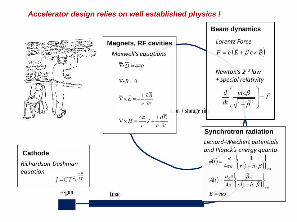
Accelerator design relies on well established physics !
Synchrotron radiation
( ) ( )
( ) ( )ω
ββ
πμ
βπεφ
hEnrce
tA
nret
ret
ret
=⎭⎬⎫
⎩⎨⎧
⋅−=
⎭⎬⎫
⎩⎨⎧
⋅−=
v
vv
v
ˆ14
ˆ11
4
0
0
Lienard‐Wiechert potentialsand Planck’s energy quanta
Richardson‐Dushman equation
Cathode
Maxwell’s equations
Magnets, RF cavities( )BcEeF
vvvr×+= β
Lorentz Force
Fcmdtd v
r
r
=⎟⎟
⎠
⎞
⎜⎜
⎝
⎛
− 21 β
β
Newton’s 2nd law+ special relativity
Beam dynamics

Machine design provides specifications and nominal settings for all components
Magnet power supplies
RF power sources
e--gun Linac
Synchrotron / storage ring
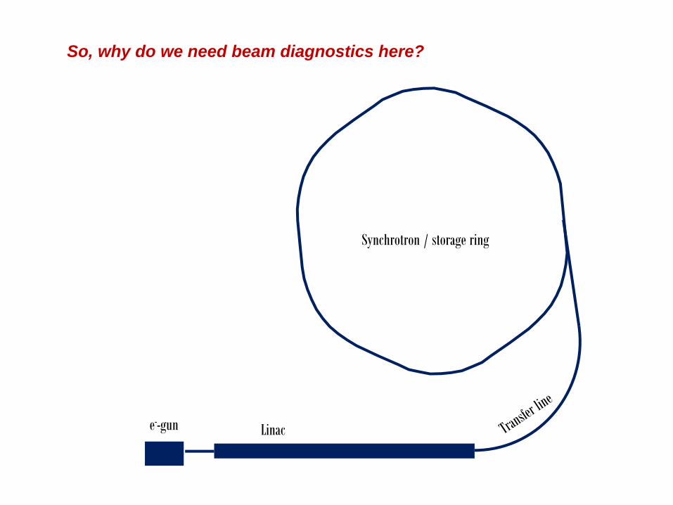
So, why do we need beam diagnostics here?
e--gun Linac
Synchrotron / storage ring
6 good reasons for beam diagnostics
Stupid things
Component tolerances and related random errors
Environmental effects
Equipment fault
Equipment set-up
Performance tuning and preservation ⇒ Laurent Nadolki’slecture tomorrow
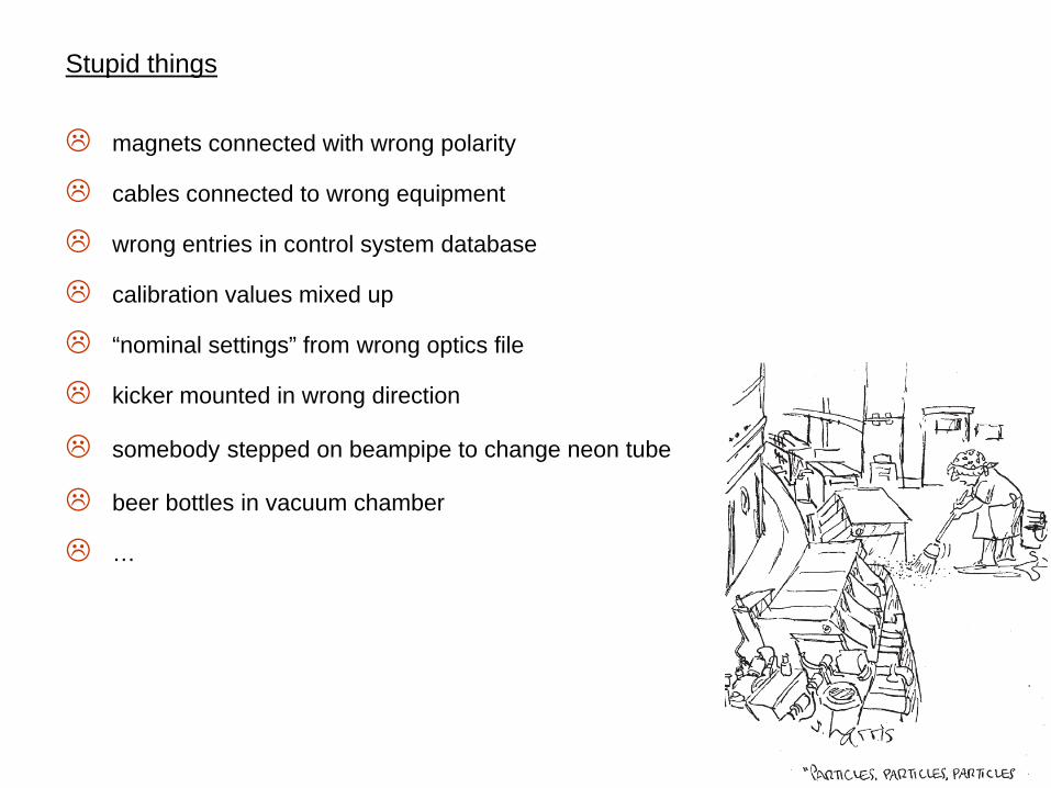
Stupid things
magnets connected with wrong polarity
cables connected to wrong equipment
wrong entries in control system database
calibration values mixed up
“nominal settings” from wrong optics file
kicker mounted in wrong direction
somebody stepped on beampipe to change neon tube
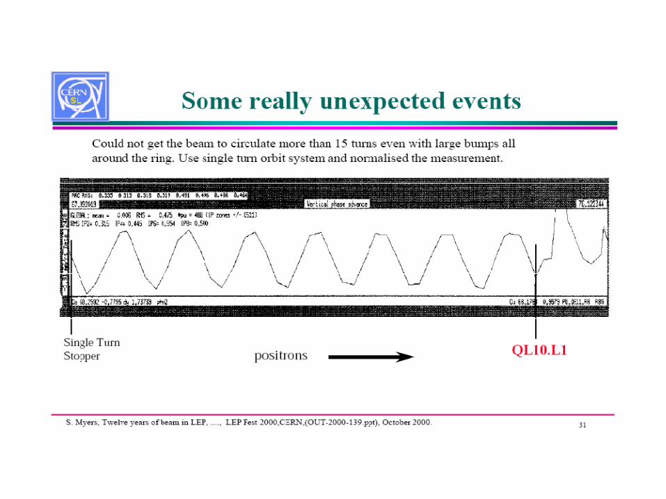
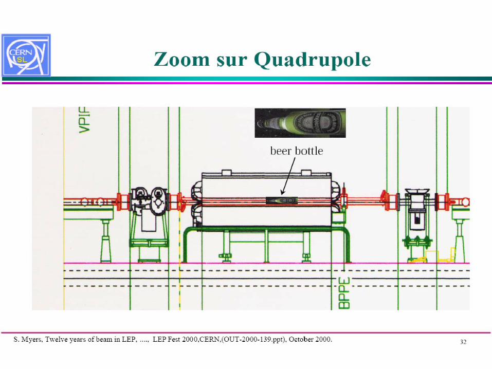
beer bottles in vacuum chamber
…

Component tolerances and related random errors
Finite precision of survey and alignment
Finite accuracy of power supplies
Ripple of power supply
Finite accuracy of magnet field measurement
Ripple of RF Amplitude
RF phase noise
Drifts (temperature, humidity, aging of component)

Dipole Quadrupole Sextupole
purpose beam deflection & sometimes focusing
beam focusing chromatic correction
unwanted, but somehow predictable side effects
sextupole component modifies chromaticityreduces acceptance
dodecapole component(usually negligible)
limits dynamic acceptance
effect of excitation errors and ripple
generates orbit errors and chromaticity deviations
generate tune errors generate chromaticity errors
most critical alignment issues
roll angle generatesvertical orbit excursionsand spurious vertical dispersion
transverse shiftsgenerate orbit excursions and spurious dispersion
roll angle generates x, y coupling
vertical shift destroys beam polarisation
vertical displacementgenerates x,y coupling
horizonal displacement generates tuneshift

Some typical values
A good survey and alignment team adjust magnets within ±150 μm of nominal positionand ±100 μrad of nominal angle.
Active alignment systems can measure and correct position of accelerator components relative to a laser or stretched wire reference within 1 μm.
Machining with precision turning lathe and milling cutter can be done with a few μm precision
Typical technical materials have thermal coefficient of expansion in range 5⋅10-6-25⋅10-6
a ΔT of 1o C of a 1m size object will therefore change it's dimensions by 5-25 μm
Rapid (>1 Hz) seismic movements ≈10-50 nm
Displacement of one quadrupole in a storage ring by 1 μm will result in a change of mean orbit amplitude of typically 1-10 μm.
In a new building or tunnel floor moves in some cases several mm per year
A 300 horizontal bending dipole with a roll error of 1 mrad will give 0.5 mrad of verticaldeflection.
Magnet power supplies have residual ripples & drifts ranging from 10-3-10-6.A 10-4 ripple on a 300 horizontal bending dipole produces a jitter on beam angle of 50μradcorresponding to 50 μm position jitters one meter downstream.

Environmental effects
Subsiding of building/tunnel foundation
Mechanical vibrations induced by water flow, vacuum pumps, water pumps, ventilation
Mechanical vibrations from nearby traffic or construction work
Seismic vibrations
Earth magnetic field
Magnetic fields from electric currents induced on vacuum chamber
Stray fields from permanent magnets in vacuum pumps and vacuum gauges
Field distortions from magnetic materials in support structures, building and equipment
Magnetic stray field from cables
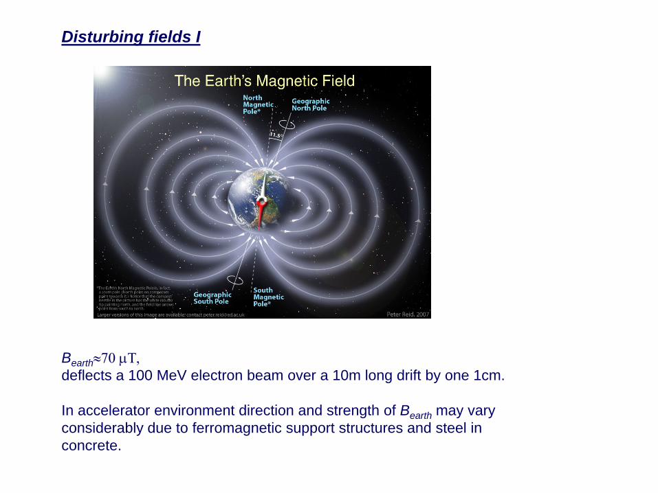
Disturbing fields I
Bearth≈70 μΤ, deflects a 100 MeV electron beam over a 10m long drift by one 1cm.
In accelerator environment direction and strength of Bearth may vary considerably due to ferromagnetic support structures and steel in concrete.
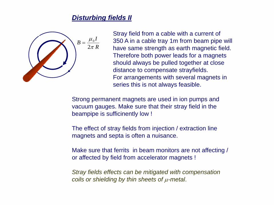
Disturbing fields II
Stray field from a cable with a current of 350 A in a cable tray 1m from beam pipe will have same strength as earth magnetic field. Therefore both power leads for a magnets should always be pulled together at close distance to compensate strayfields. For arrangements with several magnets in series this is not always feasible.
Strong permanent magnets are used in ion pumps and vacuum gauges. Make sure that their stray field in the beampipe is sufficinently low !
The effect of stray fields from injection / extraction line magnets and septa is often a nuisance.
Make sure that ferrits in beam monitors are not affecting / or affected by field from accelerator magnets !
Stray fields effects can be mitigated with compensation coils or shielding by thin sheets of μ-metal.
RI
Bπμ2
0=


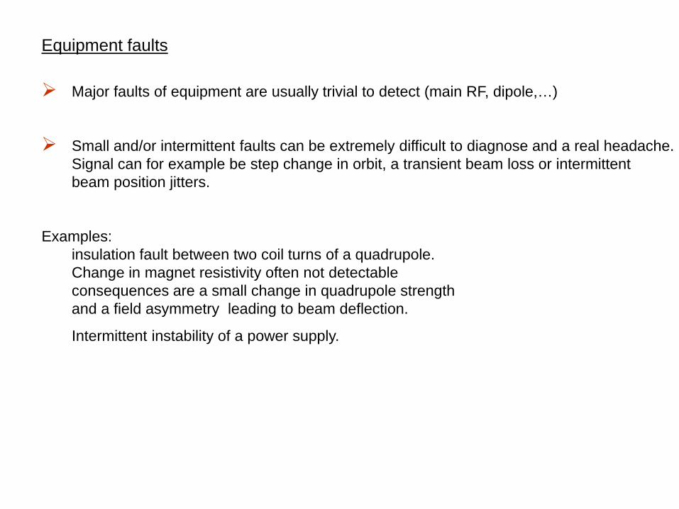
Equipment faults
Major faults of equipment are usually trivial to detect (main RF, dipole,…)
Small and/or intermittent faults can be extremely difficult to diagnose and a real headache.Signal can for example be step change in orbit, a transient beam loss or intermittentbeam position jitters.
Examples: insulation fault between two coil turns of a quadrupole.Change in magnet resistivity often not detectableconsequences are a small change in quadrupole strengthand a field asymmetry leading to beam deflection.
Intermittent instability of a power supply.
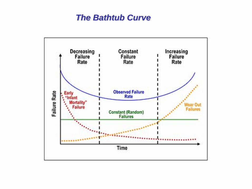
The Bathtub Curve

Equipment set-up
☺ Beam diagnostics often provides the most sensitive signals to adjust equipment parameters to their operational values.
Examples:
• Setting of RF phases between different cavities in a linac with RF measurements only would be very difficult, because very precise characterisation of all cables, connectors etc. required. With beam phasing of cavities is straight forward and precision better that <10 can be readily obtained just by optimising beam energy at end of linac.
• Tune and chromaticities settings more precisely with beam than with predictions from magnet measurement.One reason: Magnets have no “easy” power supply current ⇒ field mapping
• In electron storage ring the polarisation method allows an extremely precise measurement of beam energy, better than any magnetic field calibration.
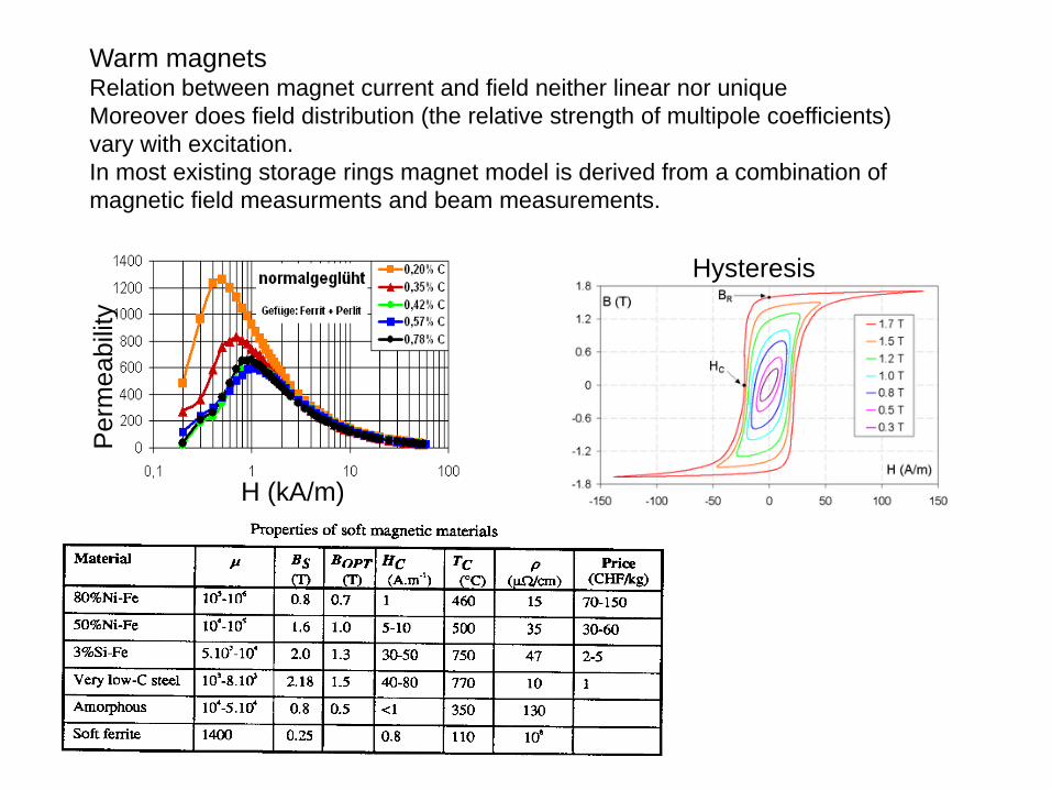
Warm magnetsRelation between magnet current and field neither linear nor uniqueMoreover does field distribution (the relative strength of multipole coefficients)vary with excitation. In most existing storage rings magnet model is derived from a combination ofmagnetic field measurments and beam measurements.
H (kA/m)
Per
mea
bilit
y
Hysteresis
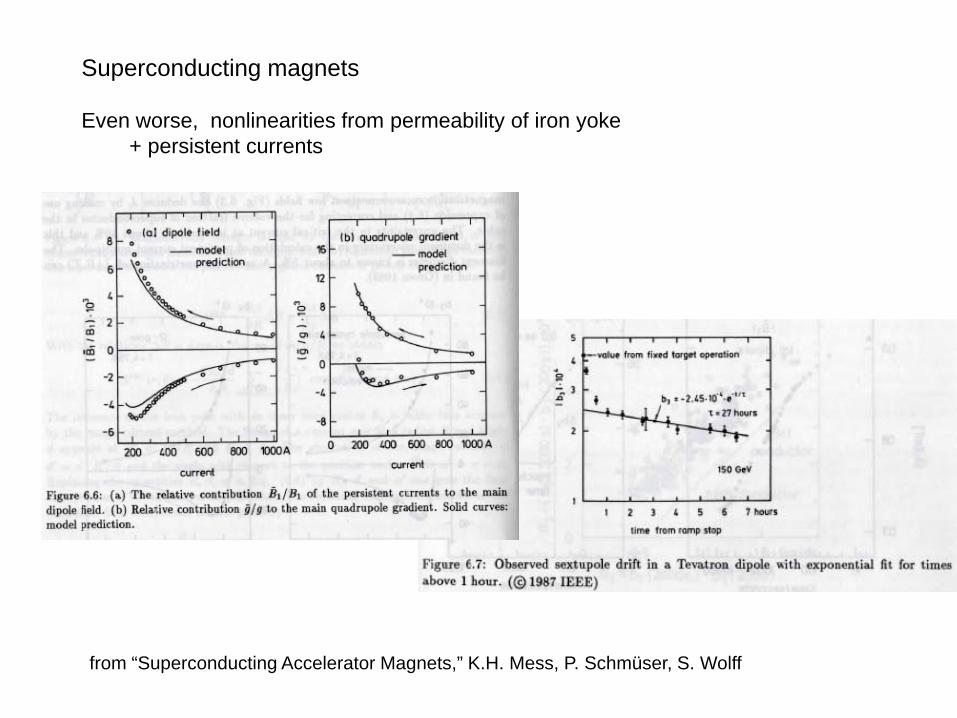
Superconducting magnets
Even worse, nonlinearities from permeability of iron yoke + persistent currents
from “Superconducting Accelerator Magnets,” K.H. Mess, P. Schmüser, S. Wolff
Yet another effect which is difficult to predict quantitatively:
In synchrotrons B induces eddy currents on vacuum chamber.These currents create a predominantly quadrupolar field, thus changing the overall focusing in proportion to ramp speed.
.
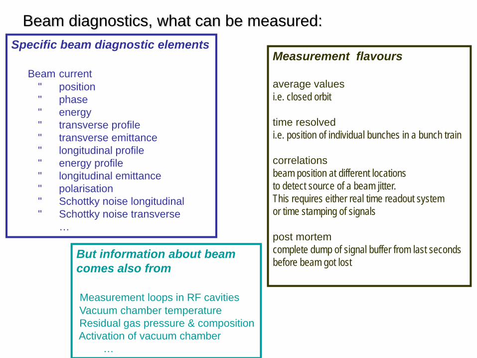
Beam diagnostics, what can be measured:Specific beam diagnostic elements
Beam current" position" phase " energy" transverse profile" transverse emittance " longitudinal profile" energy profile" longitudinal emittance " polarisation" Schottky noise longitudinal" Schottky noise transverse
…
Measurement flavours
average valuesi.e. closed orbit
time resolvedi.e. position of individual bunches in a bunch train
correlationsbeam position at different locationsto detect source of a beam jitter.This requires either real time readout system or time stamping of signals
post mortemcomplete dump of signal buffer from last seconds before beam got lost
But information about beam comes also from
Measurement loops in RF cavities Vacuum chamber temperatureResidual gas pressure & compositionActivation of vacuum chamber
…
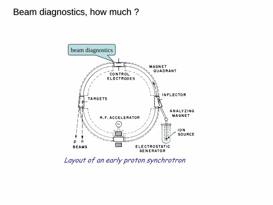
Beam diagnostics, how much ?
Layout of an early proton synchrotron
beam diagnostics

LHC beam diagnostics
Total of 1158 BPMs and ≈3000 BLMs
plus many special instruments

e+ injector 2.4 GeV
e- injector2.4 GeV
CLIC 3 TeV
not to scale
BC1
e+ DR365m
e- DR365m
booster linac, 9 GeV, 2 GHz
IP
47.9 km
drive beam accelerator2.38 GeV, 1.0 GHz
combiner rings Circumferences delay loop 72.4 m
CR1 144.8 mCR2 434.3 m
CR1CR2
delayloop
326 klystrons33 MW, 139 μs
1 km
CR2delayloop
drive beam accelerator2.38 GeV, 1.0 GHz
326 klystrons33 MW, 139 μs
1 km
CR1
TAR=120m
245m 245m
≈50000 BPM’sfor the whole complex
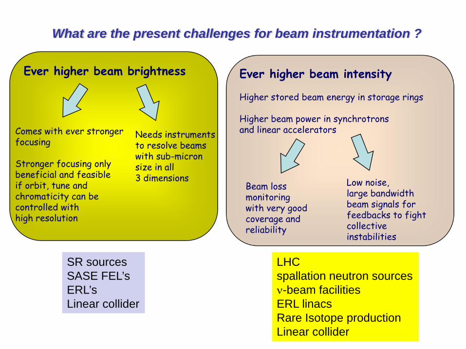
What are the present challenges for beam instrumentation ?
Ever higher beam brightness Ever higher beam intensity
Higher stored beam energy in storage rings
Higher beam power in synchrotronsand linear acceleratorsComes with ever stronger
focusing
Stronger focusing only beneficial and feasible if orbit, tune and chromaticity can be controlled with high resolution
Needs instruments to resolve beams with sub-micron size in all 3 dimensions
Beam loss monitoring with very good coverage and reliability
Low noise, large bandwidth beam signals for feedbacks to fight collective instabilities
SR sourcesSASE FEL’sERL’sLinear collider
LHCspallation neutron sourcesν-beam facilitiesERL linacsRare Isotope productionLinear collider
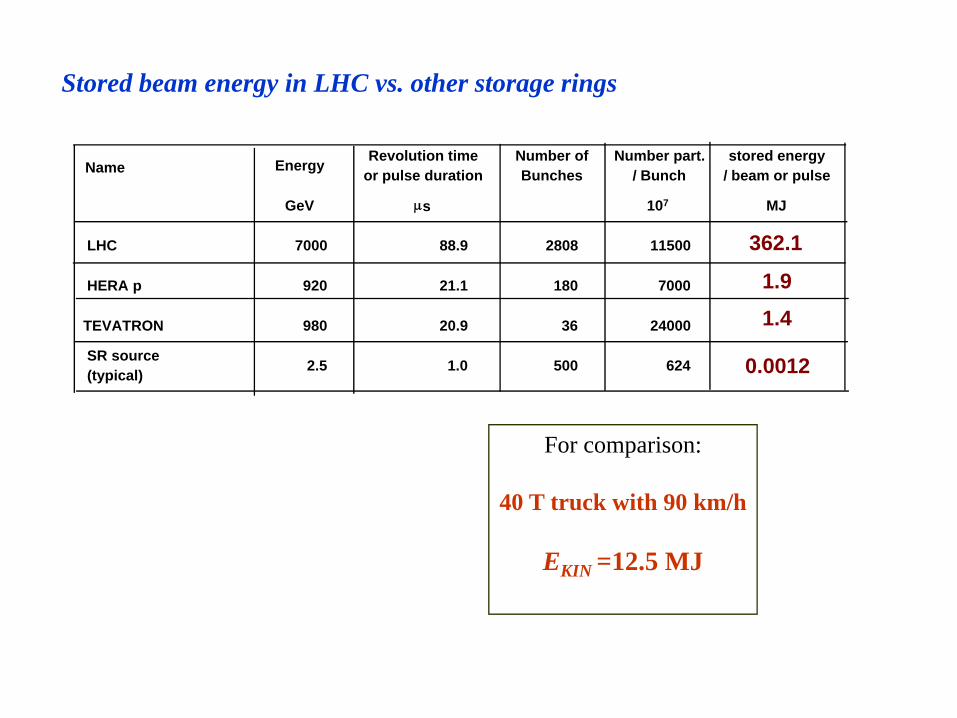
Name Energy Revolution timeor pulse duration
Number of Bunches
Number part. / Bunch
stored energy/ beam or pulse
GeV μs 107 MJ
LHC 7000 88.9 2808 11500 362.1
HERA p 920 21.1 180 7000 1.9
TEVATRON 980 20.9 36 24000 1.4SR source(typical) 2.5 1.0 500 624 0.0012
Stored beam energy in LHC vs. other storage rings
For comparison:
40 T truck with 90 km/h
EKIN =12.5 MJ

What diagnostic issue is most important for commissioning of a new accelerator ?
quote from Michel Chanel :(key player for commissioning of several rings for protons, antiprotons and ions at CERN)
Orbit and tune diagnostic have to function from day one, hour zero !

Literature
Specialised textbooks M. Minty and F. Zimmermann, “Measurement and Control of Charged Particle Beams,” Springer 2003K. Mess, P. Schmüser, S. Wolff, “Superconducting Accelerator Magnets,”World Scientific, 1996J. Tanabe, “Iron Dominated Magnets,” World Scientific 2005CAS proceedings
General accelerator physics textbooksA. Chao and M. Tigner (editors), “Handbook of Accelerator Physics and Engineering,” World Scientific, 1999H. Wiedemann, “Particle Accelerator Physics,” (2 volumes), Springer 1993K. Wille, “The Physics of Particle Accelerators : An Introduction,” Oxford University Press, 2001 S.Y. Lee, “Accelerator Physics,” World Scientific, 2004
For more accelerator book references http://uspas.fnal.gov/book.html

Thank you for your attention
and
Thanks to Michel Chanel, Tobias Dobers, Giovanni Rumolo, Piotr Skowronski and Frank Zimmermann for various inputs to this lecture