BETONexpress Example of footings - RUNET … of footings Pg. 1 Example of footings 1. FOOTING-001...
17
Example of footings Pg. 1 Example of footings 1. FOOTING-001 Symmetric footing with centric load (EC2 EN1992-1-1:2004, EC0 EN1990-1-1:2002, EC7 EN1997-1-1:2004) Concrete-Steel class: C25/30-S500 (EC2 §3) Concrete cover : Cnom=75 mm (EC2 §4.4.1) Concrete weight : 25.0 kN/m³ ȖF ȖV (EC2 Table 2.1N) 1.1. Dimensions, materials, loads Dimensions Footing Lx= 1.900 m Ly= 1.900 m Column cx= 0.300 m cy= 0.300 m Heights h= 0.700 m h1= 0.300 m Depth of footing hf= 1.200 m Base area of footing A= 3.61 m² Volume of footing V= 1.65 m³ Materials of footing Concrete-Steel class: C25/30-S500 (EN1992-1-1, §3) Concrete cover: Cnom=75 mm (EC2 §4.4.1) Effective depth of cross section d=h-d1, d1=Cnomc+(3/2)Ø=75+3x12/2=93mm, d=700-93=607mm Soil Soil bearing pressure qu= 0.200 N/mm² (MPa) 8QLW ZHLJKW RI VRLO Ȗ N1Pñ Loads Self weight of footing [ 1.65x25.00] Gf= 41.25 kN Soil weight on footing [( 3.61x 1.20- 1.65)x17.00] Gs= 45.59 kN Vertical permanent load Ng= 170.00 kN Vertical variable load Nq= 100.00 kN Ng f s Nq G G 1 software by RUNET (c) RUNET Norway as 12/03/2007 09:22:22 C:\RUNETENG\BETON\Projects\Prj0 BETONexpress
-
Upload
phunghuong -
Category
Documents
-
view
226 -
download
4
Transcript of BETONexpress Example of footings - RUNET … of footings Pg. 1 Example of footings 1. FOOTING-001...

Example of footings Pg. 1
Example of footings
1. FOOTING-001
Symmetric footing with centric load
(EC2 EN1992-1-1:2004, EC0 EN1990-1-1:2002, EC7 EN1997-1-1:2004)
Concrete-Steel class: C25/30-S500 (EC2 §3)
Concrete cover : Cnom=75 mm (EC2 §4.4.1)
Concrete weight : 25.0 kN/m³
ȖF ������ȖV ���������������������� (EC2 Table 2.1N)
1.1. Dimensions, materials, loads
Dimensions
Footing Lx= 1.900 m Ly= 1.900 m
Column cx= 0.300 m cy= 0.300 m
Heights h= 0.700 m h1= 0.300 m
Depth of footing hf= 1.200 m
Base area of footing A= 3.61 m²
Volume of footing V= 1.65 m³
Materials of footing
Concrete-Steel class: C25/30-S500 (EN1992-1-1, §3)
Concrete cover: Cnom=75 mm (EC2 §4.4.1)
Effective depth of cross section d=h-d1, d1=Cnomc+(3/2)Ø=75+3x12/2=93mm, d=700-93=607mm
Soil
Soil bearing pressure qu= 0.200 N/mm² (MPa)
8QLW�ZHLJKW�RI�VRLO����Ȗ �������N1�Pñ
Loads
Self weight of footing [ 1.65x25.00] Gf= 41.25 kN
Soil weight on footing [( 3.61x 1.20- 1.65)x17.00] Gs= 45.59 kN
Vertical permanent load Ng= 170.00 kN
Vertical variable load Nq= 100.00 kN
Ng
f
s
Nq
G
G
1
software by RUNET (c)RUNET Norway as
12/03/2007 09:22:22C:\RUNETENG\BETON\Projects\Prj0
BETONexpress
Example of footings Pg. 2
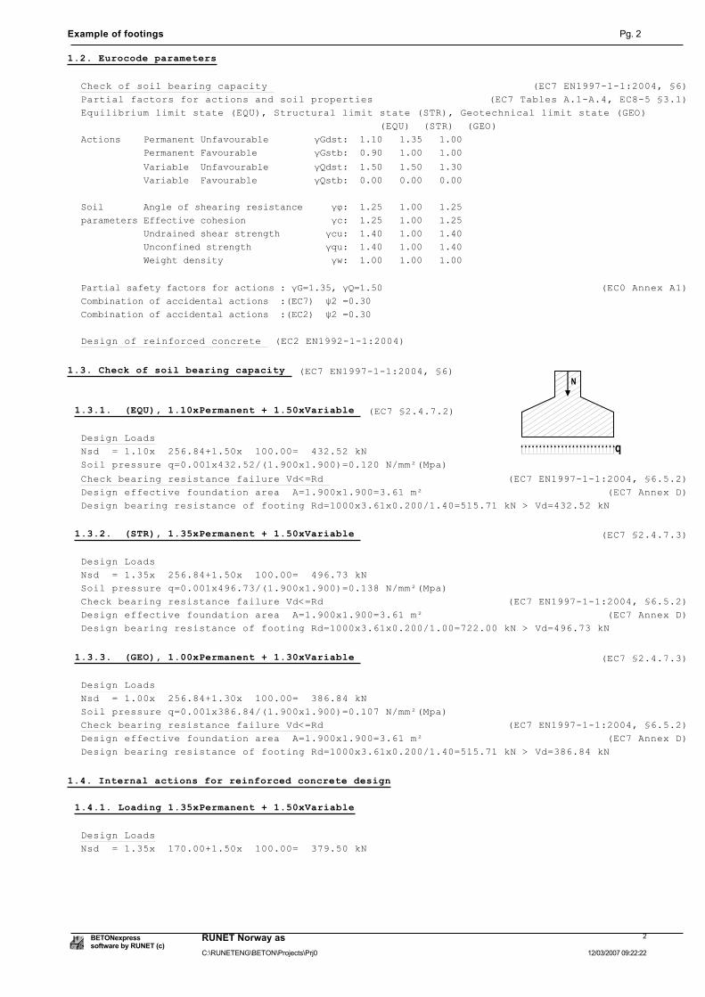
1.2. Eurocode parameters
Check of soil bearing capacity (EC7 EN1997-1-1:2004, §6)
Partial factors for actions and soil properties (EC7 Tables A.1-A.4, EC8-5 §3.1)
Equilibrium limit state (EQU), Structural limit state (STR), Geotechnical limit state (GEO)
(EQU) (STR) (GEO)
$FWLRQV����3HUPDQHQW�8QIDYRXUDEOH��������Ȗ*GVW����������������������
�����������3HUPDQHQW�)DYRXUDEOH����������Ȗ*VWE����������������������
�����������9DULDEOH��8QIDYRXUDEOH��������Ȗ4GVW����������������������
�����������9DULDEOH��)DYRXUDEOH����������Ȗ4VWE����������������������
6RLO�������$QJOH�RI�VKHDULQJ�UHVLVWDQFH�����Ȗij����������������������
SDUDPHWHUV�(IIHFWLYH�FRKHVLRQ���������������ȖF����������������������
�����������8QGUDLQHG�VKHDU�VWUHQJWK��������ȖFX����������������������
�����������8QFRQILQHG�VWUHQJWK�������������ȖTX����������������������
�����������:HLJKW�GHQVLW\�������������������ȖZ����������������������
3DUWLDO�VDIHW\�IDFWRUV�IRU�DFWLRQV���Ȗ* ������Ȗ4 ����� (EC0 Annex A1)
&RPELQDWLRQ�RI�DFFLGHQWDO�DFWLRQV����(&����ȥ�� ����
&RPELQDWLRQ�RI�DFFLGHQWDO�DFWLRQV����(&����ȥ�� ����
Design of reinforced concrete (EC2 EN1992-1-1:2004)
1.3. Check of soil bearing capacity (EC7 EN1997-1-1:2004, §6)
1.3.1. (EQU), 1.10xPermanent + 1.50xVariable (EC7 §2.4.7.2)
Design Loads
Nsd = 1.10x 256.84+1.50x 100.00= 432.52 kN
Soil pressure q=0.001x432.52/(1.900x1.900)=0.120 N/mm²(Mpa)
Check bearing resistance failure Vd<=Rd (EC7 EN1997-1-1:2004, §6.5.2)
Design effective foundation area A=1.900x1.900=3.61 m² (EC7 Annex D)
Design bearing resistance of footing Rd=1000x3.61x0.200/1.40=515.71 kN > Vd=432.52 kN
1.3.2. (STR), 1.35xPermanent + 1.50xVariable (EC7 §2.4.7.3)
Design Loads
Nsd = 1.35x 256.84+1.50x 100.00= 496.73 kN
Soil pressure q=0.001x496.73/(1.900x1.900)=0.138 N/mm²(Mpa)
Check bearing resistance failure Vd<=Rd (EC7 EN1997-1-1:2004, §6.5.2)
Design effective foundation area A=1.900x1.900=3.61 m² (EC7 Annex D)
Design bearing resistance of footing Rd=1000x3.61x0.200/1.00=722.00 kN > Vd=496.73 kN
1.3.3. (GEO), 1.00xPermanent + 1.30xVariable (EC7 §2.4.7.3)
Design Loads
Nsd = 1.00x 256.84+1.30x 100.00= 386.84 kN
Soil pressure q=0.001x386.84/(1.900x1.900)=0.107 N/mm²(Mpa)
Check bearing resistance failure Vd<=Rd (EC7 EN1997-1-1:2004, §6.5.2)
Design effective foundation area A=1.900x1.900=3.61 m² (EC7 Annex D)
Design bearing resistance of footing Rd=1000x3.61x0.200/1.40=515.71 kN > Vd=386.84 kN
1.4. Internal actions for reinforced concrete design
1.4.1. Loading 1.35xPermanent + 1.50xVariable
Design Loads
Nsd = 1.35x 170.00+1.50x 100.00= 379.50 kN
2
software by RUNET (c)RUNET Norway as
12/03/2007 09:22:22C:\RUNETENG\BETON\Projects\Prj0
BETONexpress

Example of footings Pg. 3
1.5. Design for bending (EC2 EN1992-1-1:2004, §6.1)
Msd(yy)=0.125x379.50x1.900x(1-0.300/1.900)²= 63.92 kNm
Msd(xx)=0.125x379.50x1.900x(1-0.300/1.900)²= 63.92 kNm
0VG �����N1P��E ���PP��G ���PP��.G ������[�G ����
HF�HV ����������.V ������ As= 2.49cm²
Minimum reinforcement As>=0.26bd·Fctm/fyk (As= 5.74cm²/m) (EC2 §9.3.1)
Minimum reinforcement Ø12/19.5( 5.79cm²/m)
0VG �����N1P��E ���PP��G ���PP��.G ������[�G ����
HF�HV ����������.V ������ As= 2.49cm²
Minimum reinforcement As>=0.26bd·Fctm/fyk (As= 5.74cm²/m) (EC2 §9.3.1)
Minimum reinforcement Ø12/19.5( 5.79cm²/m)
M
M
sd(yy)
sd(xx)
Reinforcement of footing
Steel reinforcement in x-x direction: Ø12/19.5( 5.79cm²/m), 11Ø12(12.43cm²)Steel reinforcement in y-y direction: Ø12/19.5( 5.79cm²/m), 11Ø12(12.43cm²)
1.6. Design for shear (EC2 EN1992-1-1:2004, §6.2)
The design for shear is covered by the design in punching shear
because the critical rupture surface is considered at angle 45°
1.7. Design for punching shear (EC2 EN1992-1-1:2004, §6.4)
Footing cantilevers in x-x, L1=0.800>d=0.607m, L2=0.800>d=0.607m
Footing cantilevers in y-y, L1=0.800>d=0.607m, L2=0.800>d=0.607m
Control perimeter, at 1.0d=0.607m<2.0d (EC2 §6.4.2.2)
we consider rupture surface at angle 45°
Ucont=(0.300+0.300+0.300+0.300)+3.14x(0.607+0.607)=5.012m
Base area within the control perimeter
Acont=0.300x0.300+0.300x1.214+0.300x1.214+3.14x0.607x0.607=1.98m²
Minimum effective height of footing at control section dm= 303mm
d
cont
contU
A
$SSOLHG�VKHDU�IRUFH�DW�FRQWURO�SHULPHWHU�9HG 1VG�ıRÂ$FRQW��YHG 9HG[ȕ�8FRQW
ıR �������������[������ �������N1�Pð��ȕ ����� (EC2 §6.4.3 Fig.6.21N)
ved=(379.50-105.12x1.98)x1.15/5.012=39.32 kN/m
Tension reinforcement at control section Asxx= 5.79cm²/m, Asyy= 5.79cm²/m
As1²=(Asxx)(Asyy)=5.79x5.79, As1=5.79 cm²
Punching shear capacity without shear reinforcement Vrdc (EC2 §6.4.4)
9UGF >&UGFÂNÂ����ȡ�ÂIFN�A�������Â��G�D�@ÂEZÂG� (EC2 Eq.6.50)
9UGF! >YPLQÂ�G�D@ÂEZÂG��G GP ���PP��D ���PP
&UGF �����ȖF ��������� �������IFN �����03D
k=1+(200/d)^½ <=2, k=1.81
ȡ� $V���EZÂG� ���������[���� ������
vmin=0.035·k^(1.50)·fck^½ = 0.43N/mm² (EC2 Eq.6.3N)
Vrd,c(min)=0.001x(0.43x2x303/607)x1000x303=130.08kN/m
Vrdc=0.001x[0.120x1.81x(0.19x25.00)^(0.333)x2x303/607]x1000x303=110.45, Vrdc=Vrcd(min)=130.08kN/m
Vsd=39.32 kN/m <= Vrdc=130.08 kN/m, shear and punching shear OK
a=d
d45o dm
3
software by RUNET (c)RUNET Norway as
12/03/2007 09:22:22C:\RUNETENG\BETON\Projects\Prj0
BETONexpress

Example of footings Pg. 4
1.8. Reinforcement anchorage (EC2 EN1992-1-1:2004, §9.8.2.2, §8.4)
x=h/2=0.150m, R=1000x0.138x0.150x1.900=39.33 kN
e=0.15b=0.045m ze=0.770 m, zi=0.900d=0.546m
Fs=R·ze/zi=39.33x0.770/0.546=55.43 kN
ıVG )V�$V ����[���������� ���03D
Basic required anchorage length (EC2 Eq.8.3)
OE�UTG �ĭ����ıVG�IEG� ������[��������� ��PP
IEG ����[����[�IFWN�����ȖF� �����03D� (EC2 §8.4.2)
Design anchorage length (EC2 §8.4.4, T.8.2)
lbd=0.70x50=35mm, Cnom=75mm>3Ø=36mm
Minimum anchorage length lb,min=max(0.30lbrqd,10Ø,100mm)=120mm
Necessary anchorage length of longitudinal reinforcement Lbd=120mm =0.120m
lbd=120mm>(x-Cnom)=75.00. Necessary bends 60mm at bar ends for anchorage
d
b
z
N
F
F
l
F
B
ze
i
e
Ed
c
s s,max
bx
A
R
h
1.9. Reinforcing bar schedule
Num type reinforcing bar [mm] items g/m [kg/m]
length[m]
weight [kg]
60 1450 60 1 1 7 12 0.888 1.570 9.76
60 1450 60 2 2 7 12 0.888 1.570 9.76
1450 3 3 2 8 0.395 1.450 1.15
1450 4 3 2 8 0.395 1.450 1.15
Total weight [kg] 21.82
4
software by RUNET (c)RUNET Norway as
12/03/2007 09:22:22C:\RUNETENG\BETON\Projects\Prj0
BETONexpress
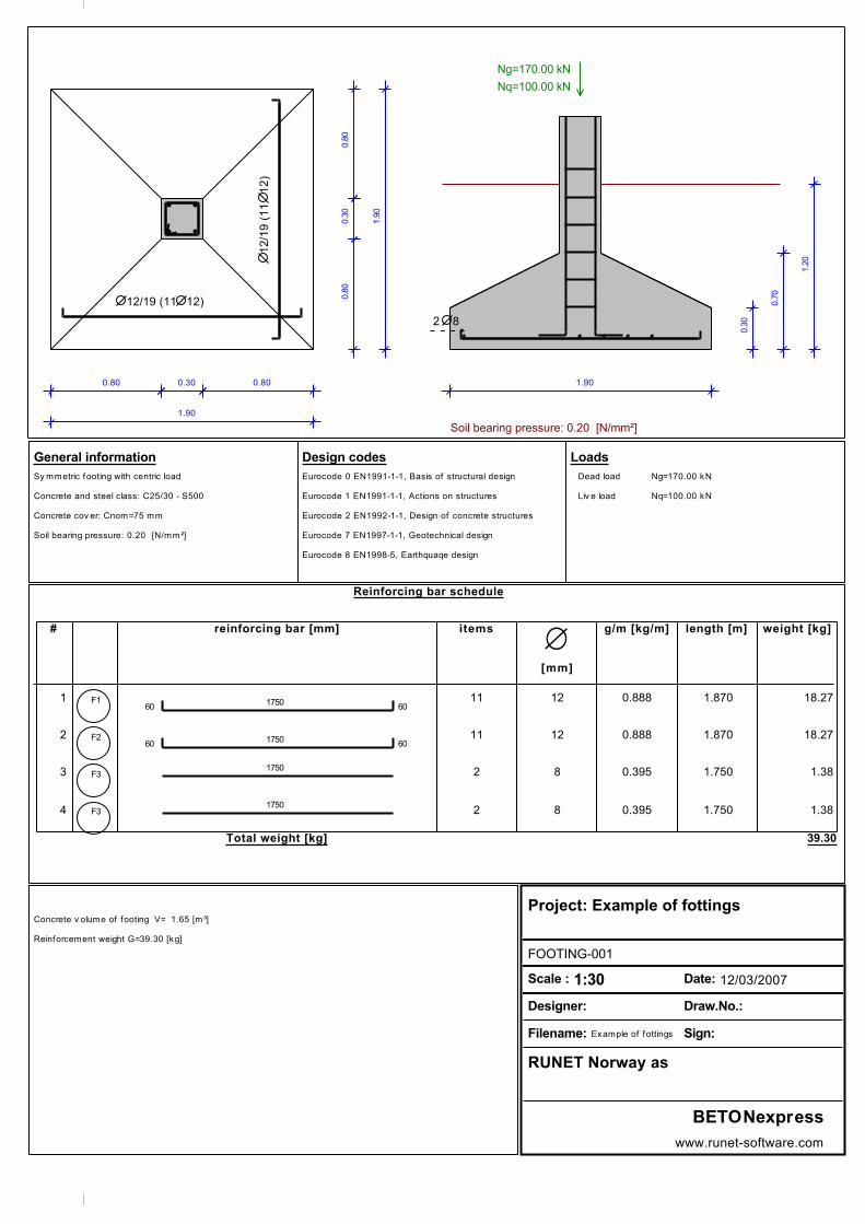
1.90
1.9
00.30
0.3
0
0.80 0.80
0.8
00.8
0
1.90
0.3
0
0.7
0
1.2
0
6RLO�EHDULQJ�SUHVVXUH��������>1�PPð@
Ng=170.00 kN
Nq=100.00 kN
12/19 (11 12)
12
/19
(1
11
2)
2 8
Reinforcing bar schedule
# reinforcing bar [mm] items
[mm]
g/m [kg/m] length [m] weight [kg]
60 1750 60 1 F1 11 12 0.888 1.870 18.27
60 1750 60 2 F2 11 12 0.888 1.870 18.27
1750 3 F3 2 8 0.395 1.750 1.38
1750 4 F3 2 8 0.395 1.750 1.38
Total weight [kg] 39.30
General information
Sy mmetric footing with centric load
Concrete and steel class: C25/30 - S500
Concrete cov er: Cnom=75 mm
Soil bearing pressure: 0.20 [N/mm²]
Design codes
Eurocode 0 EN1991-1-1, Basis of structural design
Eurocode 1 EN1991-1-1, Actions on structures
Eurocode 2 EN1992-1-1, Design of concrete structures
Eurocode 7 EN1997-1-1, Geotechnical design
Eurocode 8 EN1998-5, Earthquaqe design
Loads
Dead load Ng=170.00 kN
Liv e load Nq=100.00 kN
Concrete v olume of footing V= 1.65 [m³]
Reinforcement weight G=39.30 [kg]
Project: Example of fottings
FOOTING-001
Scale : 1:30 Date: 12/03/2007
Designer: Draw.No.:
Filename: Example of fottings Sign:
RUNET Norway as
BETONexpress
www.runet-software.com

Example of footings Pg. 5
2. FOOTING-003
Symmetric footing with eccentric load
(EC2 EN1992-1-1:2004, EC0 EN1990-1-1:2002, EC7 EN1997-1-1:2004)
Concrete-Steel class: C25/30-S500 (EC2 §3)
Concrete cover : Cnom=75 mm (EC2 §4.4.1)
Concrete weight : 25.0 kN/m³
ȖF ������ȖV ���������������������� (EC2 Table 2.1N)
2.1. Dimensions, materials, loads
Dimensions
Footing Lx= 1.600 m Ly= 1.600 m
Column cx= 0.300 m cy= 0.300 m
Heights h= 0.600 m h1= 0.300 m
Depth of footing hf= 1.200 m
Base area of footing A= 2.56 m²
Volume of footing V= 1.08 m³
Materials of footing
Concrete-Steel class: C25/30-S500 (EN1992-1-1, §3)
Concrete cover: Cnom=75 mm (EC2 §4.4.1)
Effective depth of cross section d=h-d1, d1=Cnomc+(3/2)Ø=75+3x12/2=93mm, d=600-93=507mm
Soil
Soil bearing pressure qu= 0.200 N/mm² (MPa)
8QLW�ZHLJKW�RI�VRLO����Ȗ �������N1�Pñ
Loads
permanent variable
Self weight kN [ 1.08x25.00] 27.00
Soil weight kN [( 2.56x 1.20- 1.08)x17.00] 33.86
Vertical load kN 70.00 30.00
Moment Mxx kNm 20.00 10.00
Moment Myy kNm 10.00 5.00
5
software by RUNET (c)RUNET Norway as
12/03/2007 09:22:22C:\RUNETENG\BETON\Projects\Prj0
BETONexpress

Example of footings Pg. 6
2.2. Eurocode parameters
Check of soil bearing capacity (EC7 EN1997-1-1:2004, §6)
Partial factors for actions and soil properties (EC7 Tables A.1-A.4, EC8-5 §3.1)
Equilibrium limit state (EQU), Structural limit state (STR), Geotechnical limit state (GEO)
(EQU) (STR) (GEO)
$FWLRQV����3HUPDQHQW�8QIDYRXUDEOH��������Ȗ*GVW����������������������
�����������3HUPDQHQW�)DYRXUDEOH����������Ȗ*VWE����������������������
�����������9DULDEOH��8QIDYRXUDEOH��������Ȗ4GVW����������������������
�����������9DULDEOH��)DYRXUDEOH����������Ȗ4VWE����������������������
6RLO�������$QJOH�RI�VKHDULQJ�UHVLVWDQFH�����Ȗij����������������������
SDUDPHWHUV�(IIHFWLYH�FRKHVLRQ���������������ȖF����������������������
�����������8QGUDLQHG�VKHDU�VWUHQJWK��������ȖFX����������������������
�����������8QFRQILQHG�VWUHQJWK�������������ȖTX����������������������
�����������:HLJKW�GHQVLW\�������������������ȖZ����������������������
3DUWLDO�VDIHW\�IDFWRUV�IRU�DFWLRQV���Ȗ* ������Ȗ4 ����� (EC0 Annex A1)
&RPELQDWLRQ�RI�DFFLGHQWDO�DFWLRQV����(&����ȥ�� ����
&RPELQDWLRQ�RI�DFFLGHQWDO�DFWLRQV����(&����ȥ�� ����
Design of reinforced concrete (EC2 EN1992-1-1:2004)
2.3. Check of soil bearing capacity (EC7 EN1997-1-1:2004, §6)
2.3.1. (EQU), 1.10xPermanent + 1.50xVariable (EC7 §2.4.7.2)
Design Loads
Nsd = 1.10x 130.86+1.50x 30.00= 188.95 kN
Mxxsd= 1.10x 20.00+1.50x 10.00= 37.00 kNm
Myysd= 1.10x 10.00+1.50x 5.00= 18.50 kNm
Eccentricities, soil pressures, footing area
relative eccentricity ex/Lx=Myy/(N·Lx)= 0.061
relative eccentricity ey/Ly=Mxx/(N·Ly)= 0.122
soil pressure q1= 0.155 N/mm²
soil pressure q2= 0.047 N/mm²
soil pressure q3= 0.000 N/mm²
soil pressure q4= 0.101 N/mm²
]HUR�SUHVVXUH�OLQH�[R ����P��\R ����P��ș ���
effective footing area 99.51%
� �
��
Check bearing resistance failure Vd<=Rd (EC7 EN1997-1-1:2004, §6.5.2)
relative load eccentricities ex/Lx=Myy/(N·Lx)=0.061, ey/Ly=Mxx/(N·Ly)=0.122
relative load eccentricities <=0.333 (EC7 §6.5.4)
effective design length of footing L'=1.600x(1-2x0.061)=1.405 m (EC7 Annex D)
effective design width of footing B'=1.600x(1-2x0.122)=1.210 m
effective design area of footing L'B'=1.405x1.210=1.70 m²
Design bearing resistance of footing Rd=1000x1.70x0.200/1.40=242.86 kN > Vd=188.95 kN
Effective footing area 99.51%>50.00% (EC7 §6.5.4)
2.3.2. (STR), 1.35xPermanent + 1.50xVariable (EC7 §2.4.7.3)
Design Loads
Nsd = 1.35x 130.86+1.50x 30.00= 221.66 kN
Mxxsd= 1.35x 20.00+1.50x 10.00= 42.00 kNm
Myysd= 1.35x 10.00+1.50x 5.00= 21.00 kNm
6
software by RUNET (c)RUNET Norway as
12/03/2007 09:22:22C:\RUNETENG\BETON\Projects\Prj0
BETONexpress

Example of footings Pg. 7
Eccentricities, soil pressures, footing area
relative eccentricity ex/Lx=Myy/(N·Lx)= 0.059
relative eccentricity ey/Ly=Mxx/(N·Ly)= 0.118
soil pressure q1= 0.179 N/mm²
soil pressure q2= 0.056 N/mm²
soil pressure q3= 0.000 N/mm²
soil pressure q4= 0.117 N/mm²
]HUR�SUHVVXUH�OLQH�[R ����P��\R ����P��ș ���
effective footing area 99.80%
� �
��
Check bearing resistance failure Vd<=Rd (EC7 EN1997-1-1:2004, §6.5.2)
relative load eccentricities ex/Lx=Myy/(N·Lx)=0.059, ey/Ly=Mxx/(N·Ly)=0.118
relative load eccentricities <=0.333 (EC7 §6.5.4)
effective design length of footing L'=1.600x(1-2x0.059)=1.411 m (EC7 Annex D)
effective design width of footing B'=1.600x(1-2x0.118)=1.222 m
effective design area of footing L'B'=1.411x1.222=1.72 m²
Design bearing resistance of footing Rd=1000x1.72x0.200/1.00=344.00 kN > Vd=221.66 kN
Effective footing area 99.80%>50.00% (EC7 §6.5.4)
2.3.3. (GEO), 1.00xPermanent + 1.30xVariable (EC7 §2.4.7.3)
Design Loads
Nsd = 1.00x 130.86+1.30x 30.00= 169.86 kN
Mxxsd= 1.00x 20.00+1.30x 10.00= 33.00 kNm
Myysd= 1.00x 10.00+1.30x 5.00= 16.50 kNm
Eccentricities, soil pressures, footing area
relative eccentricity ex/Lx=Myy/(N·Lx)= 0.061
relative eccentricity ey/Ly=Mxx/(N·Ly)= 0.121
soil pressure q1= 0.139 N/mm²
soil pressure q2= 0.042 N/mm²
soil pressure q3= 0.000 N/mm²
soil pressure q4= 0.090 N/mm²
]HUR�SUHVVXUH�OLQH�[R ����P��\R ����P��ș ���
effective footing area 99.58%
� �
��
Check bearing resistance failure Vd<=Rd (EC7 EN1997-1-1:2004, §6.5.2)
relative load eccentricities ex/Lx=Myy/(N·Lx)=0.061, ey/Ly=Mxx/(N·Ly)=0.121
relative load eccentricities <=0.333 (EC7 §6.5.4)
effective design length of footing L'=1.600x(1-2x0.061)=1.405 m (EC7 Annex D)
effective design width of footing B'=1.600x(1-2x0.121)=1.213 m
effective design area of footing L'B'=1.405x1.213=1.70 m²
Design bearing resistance of footing Rd=1000x1.70x0.200/1.40=242.86 kN > Vd=169.86 kN
Effective footing area 99.58%>50.00% (EC7 §6.5.4)
2.4. Internal actions for reinforced concrete design
Moments M and shearing forces V, are computed at column faces.
Shearing forces V* are computed at distance d=0.507m from the column face.
They are computed, by numerical integration of the soil pressure under the footing.
2.4.1. Loading 1.35xPermanent + 1.50xVariable
Design Loads
Nsd = 1.35x 130.86+1.50x 30.00= 221.66 kN
Mxxsd= 1.35x 20.00+1.50x 10.00= 42.00 kNm
Myysd= 1.35x 10.00+1.50x 5.00= 21.00 kNm
7
software by RUNET (c)RUNET Norway as
12/03/2007 09:22:22C:\RUNETENG\BETON\Projects\Prj0
BETONexpress

Example of footings Pg. 8
Eccentricities, soil pressures, footing area
relative load eccentricities ex/Lx=Myy/(N·Lx)=0.059, ey/Ly=Mxx/(N·Ly)=0.118
soil pressures q1=0.179, q2=0.056, q3=0.000, q4=0.117 N/mm²
]HUR�SUHVVXUH�OLQH�[R ����P��\R ����P��ș ���
pressure due to self weight+soil weight qg=0.001x1.35x(27.00+33.86)/2.56=0.032 N/mm²
Shear at critical section + (self weight+soil weight) q·Acont+qg·A=165.24 kN
Internal actions (bending moments, shearing forces)
Myy(1)= 25.99 kNm, V(1)= 76.23 kN, V*(1)= 19.00 kN
Myy(2)= 12.07 kNm, V(2)= 41.05 kN, V*(2)= 7.25 kN
Mxx(3)= 33.57 kNm, V(3)= 95.28 kN, V*(3)= 25.45 kN
Mxx(4)= 4.85 kNm, V(4)= 22.12 kN, V*(4)= 1.62 kN
2.5. Design for bending (EC2 EN1992-1-1:2004, §6.1)
Maximum design moments
Msd(yy)= 25.99 kNm, b= 300 mm, d= 507 mm
Msd(xx)= 33.57 kNm, b= 300 mm, d= 507 mm
0VG �����N1P��E ���PP��G ���PP��.G ������[�G ����
HF�HV ����������.V ������ As= 1.20cm²
Minimum reinforcement As>=0.26bd·Fctm/fyk (As= 4.11cm²/m) (EC2 §9.3.1)
Minimum reinforcement Ø12/27.5( 4.11cm²/m)
0VG �����N1P��E ���PP��G ���PP��.G ������[�G ����
HF�HV ����������.V ������ As= 1.56cm²
Minimum reinforcement As>=0.26bd·Fctm/fyk (As= 4.11cm²/m) (EC2 §9.3.1)
Minimum reinforcement Ø12/27.5( 4.11cm²/m)
M
M
sd(yy)
sd(xx)
Reinforcement of footing
Steel reinforcement in x-x direction: Ø12/27.5( 4.11cm²/m), 7Ø12( 7.91cm²)Steel reinforcement in y-y direction: Ø12/27.5( 4.11cm²/m), 7Ø12( 7.91cm²)
2.6. Design for shear (EC2 EN1992-1-1:2004, §6.2)
The design for shear is covered by the design in punching shear
because the critical rupture surface is considered at angle 45°
2.7. Design for punching shear (EC2 EN1992-1-1:2004, §6.4)
Footing cantilevers in x-x, L1=0.650>d=0.507m, L2=0.650>d=0.507m
Footing cantilevers in y-y, L1=0.650>d=0.507m, L2=0.650>d=0.507m
Control perimeter, at 1.0d=0.507m<2.0d (EC2 §6.4.2.2)
we consider rupture surface at angle 45°
Ucont=(0.300+0.300+0.300+0.300)+3.14x(0.507+0.507)=4.384m
Base area within the control perimeter
Acont=0.300x0.300+0.300x1.014+0.300x1.014+3.14x0.507x0.507=1.51m²
Minimum effective height of footing at control section dm= 273mm
d
cont
contU
A
$SSOLHG�VKHDU�IRUFH�DW�FRQWURO�SHULPHWHU�9HG 1VG�ıRÂ$FRQW��YHG 9HG[ȕ�8FRQW
YHG ���������������[��������� ������N1�P��ȕ ����� (EC2 §6.4.3 Fig.6.21N)
Tension reinforcement at control section Asxx= 4.11cm²/m, Asyy= 4.11cm²/m
As1²=(Asxx)(Asyy)=4.11x4.11, As1=4.11 cm²
8
software by RUNET (c)RUNET Norway as
12/03/2007 09:22:22C:\RUNETENG\BETON\Projects\Prj0
BETONexpress

Example of footings Pg. 9
Punching shear capacity without shear reinforcement Vrdc (EC2 §6.4.4)
9UGF >&UGFÂNÂ����ȡ�ÂIFN�A�������Â��G�D�@ÂEZÂG� (EC2 Eq.6.50)
9UGF! >YPLQÂ�G�D@ÂEZÂG��G GP ���PP��D ���PP
&UGF �����ȖF ��������� �������IFN �����03D
k=1+(200/d)^½ <=2, k=1.86
ȡ� $V���EZÂG� ���������[���� ������
vmin=0.035·k^(1.50)·fck^½ = 0.44N/mm² (EC2 Eq.6.3N)
Vrd,c(min)=0.001x(0.44x2x273/507)x1000x273=129.36kN/m
Vrdc=0.001x[0.120x1.86x(0.15x25.00)^(0.333)x2x273/507]x1000x273=101.95, Vrdc=Vrcd(min)=129.36kN/m
Vsd=19.31 kN/m <= Vrdc=129.36 kN/m, shear and punching shear OK
a=d
d45o dm
2.8. Reinforcement anchorage (EC2 EN1992-1-1:2004, §9.8.2.2, §8.4)
x=h/2=0.150m, R=1000x0.179x0.150x1.600=42.93 kN
e=0.15b=0.045m ze=0.620 m, zi=0.900d=0.456m
Fs=R·ze/zi=42.93x0.620/0.456=58.33 kN
ıVG )V�$V ����[��������� ���03D
Basic required anchorage length (EC2 Eq.8.3)
OE�UTG �ĭ����ıVG�IEG� ������[��������� ��PP
IEG ����[����[�IFWN�����ȖF� �����03D� (EC2 §8.4.2)
Design anchorage length (EC2 §8.4.4, T.8.2)
lbd=0.70x82=58mm, Cnom=75mm>3Ø=36mm
Minimum anchorage length lb,min=max(0.30lbrqd,10Ø,100mm)=120mm
Necessary anchorage length of longitudinal reinforcement Lbd=120mm =0.120m
lbd=120mm>(x-Cnom)=75.00. Necessary bends 60mm at bar ends for anchorage
d
b
z
N
F
F
l
F
B
ze
i
e
Ed
c
s s,max
bx
A
R
h
2.9. Reinforcing bar schedule
Num type reinforcing bar [mm] items g/m [kg/m]
length[m]
weight [kg]
60 1450 60 5 1 7 12 0.888 1.570 9.76
60 1450 60 6 2 7 12 0.888 1.570 9.76
1450 7 3 2 8 0.395 1.450 1.15
1450 8 3 2 8 0.395 1.450 1.15
Total weight [kg] 21.82
9
software by RUNET (c)RUNET Norway as
12/03/2007 09:22:22C:\RUNETENG\BETON\Projects\Prj0
BETONexpress

1.60
1.6
0
0.30
0.3
0
0.65 0.65
0.6
50.6
5
1.60
0.3
0
0.6
0
1.2
0
6RLO�EHDULQJ�SUHVVXUH��������>1�PPð@
Dead Live Seismic
N [kN] 70.00 30.00 0.00
Mxx [kNm] 20.00 10.00 0.00
Myy [kNm] 10.00 5.00 0.00
12/28 (7 12)
12
/28
(7
12
)
2 8
Reinforcing bar schedule
# reinforcing bar [mm] items
[mm]
g/m [kg/m] length [m] weight [kg]
60 1450 60 1 F1 7 12 0.888 1.570 9.76
60 1450 60 2 F2 7 12 0.888 1.570 9.76
1450 3 F3 2 8 0.395 1.450 1.15
1450 4 F3 2 8 0.395 1.450 1.15
Total weight [kg] 21.82
General information
Sy mmetric footing with eccentric load
Concrete and steel class: C25/30 - S500
Concrete cov er: Cnom=75 mm
Soil bearing pressure: 0.20 [N/mm²]
Design codes
Eurocode 0 EN1991-1-1, Basis of structural design
Eurocode 1 EN1991-1-1, Actions on structures
Eurocode 2 EN1992-1-1, Design of concrete structures
Eurocode 7 EN1997-1-1, Geotechnical design
Eurocode 8 EN1998-5, Earthquaqe design
Loads
Dead Liv e Seismic
N [kN] 70.00 30.00 0.00
Mxx [kNm] 20.00 10.00 0.00
My y [kNm] 10.00 5.00 0.00
Concrete v olume of footing V= 1.08 [m³]
Reinforcement weight G=21.82 [kg]
Project: Example of fottings 12/03/2007
FOOTING-003
Scale : 1:30 Date: 12/03/2007
Designer: Draw.No.:
Filename: Example of fottings Sign:
RUNET Norway as
BETONexpress
www.runet-software.com

Example of footings Pg. 10
3. FOOTING-005
Asymmetric footing with eccentric load
(EC2 EN1992-1-1:2004, EC0 EN1990-1-1:2002, EC7 EN1997-1-1:2004)
Concrete-Steel class: C25/30-S500 (EC2 §3)
Concrete cover : Cnom=75 mm (EC2 §4.4.1)
Concrete weight : 25.0 kN/m³
ȖF ������ȖV ���������������������� (EC2 Table 2.1N)
3.1. Dimensions, materials, loads
Dimensions
Footing Lx= 1.700 m Ly= 1.600 m
Column cx= 0.300 m cy= 0.300 m
Eccentr. ex=-0.400 m ey=-0.350 m
Heights h= 0.600 m h1= 0.300 m
Depth of footing hf= 1.200 m
Base area of footing A= 2.72 m²
Volume of footing V= 1.15 m³
Materials of footing
Concrete-Steel class: C25/30-S500 (EN1992-1-1, §3)
Concrete cover: Cnom=75 mm (EC2 §4.4.1)
Effective depth of cross section d=h-d1, d1=Cnomc+(3/2)Ø=75+3x12/2=93mm, d=600-93=507mm
Soil
Soil bearing pressure qu= 0.200 N/mm² (MPa)
8QLW�ZHLJKW�RI�VRLO����Ȗ �������N1�Pñ
Loads
permanent variable
Self weight kN [ 1.15x25.00] 28.75
Soil weight kN [( 2.72x 1.20- 1.15)x17.00] 35.94
Vertical load kN 70.00 30.00
Moment Mxx kNm 0.00 0.00
Moment Myy kNm 0.00 0.00
10
software by RUNET (c)RUNET Norway as
12/03/2007 09:22:22C:\RUNETENG\BETON\Projects\Prj0
BETONexpress

Example of footings Pg. 11
3.2. Eurocode parameters
Check of soil bearing capacity (EC7 EN1997-1-1:2004, §6)
Partial factors for actions and soil properties (EC7 Tables A.1-A.4, EC8-5 §3.1)
Equilibrium limit state (EQU), Structural limit state (STR), Geotechnical limit state (GEO)
(EQU) (STR) (GEO)
$FWLRQV����3HUPDQHQW�8QIDYRXUDEOH��������Ȗ*GVW����������������������
�����������3HUPDQHQW�)DYRXUDEOH����������Ȗ*VWE����������������������
�����������9DULDEOH��8QIDYRXUDEOH��������Ȗ4GVW����������������������
�����������9DULDEOH��)DYRXUDEOH����������Ȗ4VWE����������������������
6RLO�������$QJOH�RI�VKHDULQJ�UHVLVWDQFH�����Ȗij����������������������
SDUDPHWHUV�(IIHFWLYH�FRKHVLRQ���������������ȖF����������������������
�����������8QGUDLQHG�VKHDU�VWUHQJWK��������ȖFX����������������������
�����������8QFRQILQHG�VWUHQJWK�������������ȖTX����������������������
�����������:HLJKW�GHQVLW\�������������������ȖZ����������������������
3DUWLDO�VDIHW\�IDFWRUV�IRU�DFWLRQV���Ȗ* ������Ȗ4 ����� (EC0 Annex A1)
&RPELQDWLRQ�RI�DFFLGHQWDO�DFWLRQV����(&����ȥ�� ����
&RPELQDWLRQ�RI�DFFLGHQWDO�DFWLRQV����(&����ȥ�� ����
Design of reinforced concrete (EC2 EN1992-1-1:2004)
3.3. Check of soil bearing capacity (EC7 EN1997-1-1:2004, §6)
3.3.1. (EQU), 1.10xPermanent + 1.50xVariable (EC7 §2.4.7.2)
Design Loads
Nsd = 1.10x 134.69+1.50x 30.00 = 193.16 kN
Mxxsd= 1.10x 0.00+1.50x 0.00+(-0.35)x 122.00= -42.70 kNm
Myysd= 1.10x 0.00+1.50x 0.00+(-0.40)x 122.00= -48.80 kNm
(1.10x70.00+1.50x30.00=122.00)
Eccentricities, soil pressures, footing area
relative eccentricity ex/Lx=Myy/(N·Lx)=-0.149
relative eccentricity ey/Ly=Mxx/(N·Ly)=-0.138
soil pressure q1= 0.000 N/mm²
soil pressure q2= 0.063 N/mm²
soil pressure q3= 0.204 N/mm²
soil pressure q4= 0.074 N/mm²
]HUR�SUHVVXUH�OLQH�[R ����P��\R ����P��ș ���
effective footing area 87.52%
� �
��
Check bearing resistance failure Vd<=Rd (EC7 EN1997-1-1:2004, §6.5.2)
relative load eccentricities ex/Lx=Myy/(N·Lx)=0.149, ey/Ly=Mxx/(N·Ly)=0.138
relative load eccentricities <=0.333 (EC7 §6.5.4)
effective design length of footing L'=1.700x(1-2x0.149)=1.193 m (EC7 Annex D)
effective design width of footing B'=1.600x(1-2x0.138)=1.158 m
effective design area of footing L'B'=1.193x1.158=1.38 m²
Design bearing resistance of footing Rd=1000x1.38x0.200/1.40=197.14 kN > Vd=193.16 kN
Effective footing area 87.52%>50.00% (EC7 §6.5.4)
3.3.2. (STR), 1.35xPermanent + 1.50xVariable (EC7 §2.4.7.3)
Design Loads
Nsd = 1.35x 134.69+1.50x 30.00 = 226.83 kN
Mxxsd= 1.35x 0.00+1.50x 0.00+(-0.35)x 139.50= -48.82 kNm
Myysd= 1.35x 0.00+1.50x 0.00+(-0.40)x 139.50= -55.80 kNm
(1.35x70.00+1.50x30.00=139.50)
11
software by RUNET (c)RUNET Norway as
12/03/2007 09:22:22C:\RUNETENG\BETON\Projects\Prj0
BETONexpress

Example of footings Pg. 12
Eccentricities, soil pressures, footing area
relative eccentricity ex/Lx=Myy/(N·Lx)=-0.145
relative eccentricity ey/Ly=Mxx/(N·Ly)=-0.135
soil pressure q1= 0.000 N/mm²
soil pressure q2= 0.075 N/mm²
soil pressure q3= 0.234 N/mm²
soil pressure q4= 0.087 N/mm²
]HUR�SUHVVXUH�OLQH�[R ����P��\R ����P��ș ���
effective footing area 88.66%
� �
��
Check bearing resistance failure Vd<=Rd (EC7 EN1997-1-1:2004, §6.5.2)
relative load eccentricities ex/Lx=Myy/(N·Lx)=0.145, ey/Ly=Mxx/(N·Ly)=0.135
relative load eccentricities <=0.333 (EC7 §6.5.4)
effective design length of footing L'=1.700x(1-2x0.145)=1.207 m (EC7 Annex D)
effective design width of footing B'=1.600x(1-2x0.135)=1.168 m
effective design area of footing L'B'=1.207x1.168=1.41 m²
Design bearing resistance of footing Rd=1000x1.41x0.200/1.00=282.00 kN > Vd=226.83 kN
Effective footing area 88.66%>50.00% (EC7 §6.5.4)
3.3.3. (GEO), 1.00xPermanent + 1.30xVariable (EC7 §2.4.7.3)
Design Loads
Nsd = 1.00x 134.69+1.30x 30.00 = 173.69 kN
Mxxsd= 1.00x 0.00+1.30x 0.00+(-0.35)x 109.00= -38.15 kNm
Myysd= 1.00x 0.00+1.30x 0.00+(-0.40)x 109.00= -43.60 kNm
(1.00x70.00+1.30x30.00=109.00)
Eccentricities, soil pressures, footing area
relative eccentricity ex/Lx=Myy/(N·Lx)=-0.148
relative eccentricity ey/Ly=Mxx/(N·Ly)=-0.137
soil pressure q1= 0.000 N/mm²
soil pressure q2= 0.057 N/mm²
soil pressure q3= 0.183 N/mm²
soil pressure q4= 0.067 N/mm²
]HUR�SUHVVXUH�OLQH�[R ����P��\R ����P��ș ���
effective footing area 87.80%
� �
��
Check bearing resistance failure Vd<=Rd (EC7 EN1997-1-1:2004, §6.5.2)
relative load eccentricities ex/Lx=Myy/(N·Lx)=0.148, ey/Ly=Mxx/(N·Ly)=0.137
relative load eccentricities <=0.333 (EC7 §6.5.4)
effective design length of footing L'=1.700x(1-2x0.148)=1.197 m (EC7 Annex D)
effective design width of footing B'=1.600x(1-2x0.137)=1.162 m
effective design area of footing L'B'=1.197x1.162=1.39 m²
Design bearing resistance of footing Rd=1000x1.39x0.200/1.40=198.57 kN > Vd=173.69 kN
Effective footing area 87.80%>50.00% (EC7 §6.5.4)
3.4. Internal actions for reinforced concrete design
Moments M and shearing forces V, are computed at column faces.
Shearing forces V* are computed at distance d=0.507m from the column face.
They are computed, by numerical integration of the soil pressure under the footing.
3.4.1. Loading 1.35xPermanent + 1.50xVariable
Design Loads
Nsd = 1.35x 134.69+1.50x 30.00 = 226.83 kN
Mxxsd= 1.35x 0.00+1.50x 0.00+(-0.35)x 139.50= -48.82 kNm
Myysd= 1.35x 0.00+1.50x 0.00+(-0.40)x 139.50= -55.80 kNm
(1.35x70.00+1.50x30.00=139.50)
12
software by RUNET (c)RUNET Norway as
12/03/2007 09:22:22C:\RUNETENG\BETON\Projects\Prj0
BETONexpress

Example of footings Pg. 13
Eccentricities, soil pressures, footing area
relative load eccentricities ex/Lx=Myy/(N·Lx)=-0.145, ey/Ly=Mxx/(N·Ly)=-0.135
soil pressures q1=0.000, q2=0.075, q3=0.234, q4=0.087 N/mm²
]HUR�SUHVVXUH�OLQH�[R ����P��\R ����P��ș ���
pressure due to self weight+soil weight qg=0.001x1.35x(28.75+35.94)/2.72=0.032 N/mm²
Shear at critical section + (self weight+soil weight) q·Acont+qg·A=206.05 kN
Internal actions (bending moments, shearing forces)
Myy(1)= 21.55 kNm, V(1)= 59.07 kN, V*(1)= 16.85 kN
Myy(2)= 8.34 kNm, V(2)= 55.50 kN, V*(2)= 0.00 kN
Mxx(3)= 20.71 kNm, V(3)= 58.80 kN, V*(3)= 16.38 kN
Mxx(4)= 8.63 kNm, V(4)= 55.87 kN, V*(4)= 0.00 kN
3.5. Design for bending (EC2 EN1992-1-1:2004, §6.1)
Maximum design moments
Msd(yy)= 21.55 kNm, b= 300 mm, d= 507 mm
Msd(xx)= 20.71 kNm, b= 300 mm, d= 507 mm
0VG �����N1P��E ���PP��G ���PP��.G ������[�G ����
HF�HV ����������.V ������ As= 0.99cm²
Minimum reinforcement As>=0.26bd·Fctm/fyk (As= 4.11cm²/m) (EC2 §9.3.1)
Minimum reinforcement Ø12/27.5( 4.11cm²/m)
0VG �����N1P��E ���PP��G ���PP��.G ������[�G ����
HF�HV ����������.V ������ As= 0.95cm²
Minimum reinforcement As>=0.26bd·Fctm/fyk (As= 4.11cm²/m) (EC2 §9.3.1)
Minimum reinforcement Ø12/27.5( 4.11cm²/m)
M
M
sd(yy)
sd(xx)
Reinforcement of footing
Steel reinforcement in x-x direction: Ø12/27.5( 4.11cm²/m), 7Ø12( 7.91cm²)Steel reinforcement in y-y direction: Ø12/27.5( 4.11cm²/m), 7Ø12( 7.91cm²)
3.6. Design for shear (EC2 EN1992-1-1:2004, §6.2)
The design for shear is covered by the design in punching shear
because the critical rupture surface is considered at angle 45°
3.7. Design for punching shear (EC2 EN1992-1-1:2004, §6.4)
Footing cantilevers in x-x, L1=1.100>d=0.507m, L2=0.300<d=0.507m
Footing cantilevers in y-y, L1=1.000>d=0.507m, L2=0.300<d=0.507m
Control perimeter, at 1.0d=0.507m<2.0d (EC2 §6.4.2.2)
we consider rupture surface at angle 45°
Ucont=(0.300+0.000+0.000+0.300)+3.14x(0.254+0.254)=2.192m
Base area within the control perimeter
Acont=0.300x0.300+0.300x0.507+0.300x0.507+3.14x0.254x0.254=0.60m²
Minimum effective height of footing at control section dm= 207mm
d
cont
contU
A
$SSOLHG�VKHDU�IRUFH�DW�FRQWURO�SHULPHWHU�9HG 1VG�ıRÂ$FRQW��YHG 9HG[ȕ�8FRQW
YHG ���������������[��������� ������N1�P��ȕ ����� (EC2 §6.4.3 Fig.6.21N)
Tension reinforcement at control section Asxx= 4.11cm²/m, Asyy= 4.11cm²/m
As1²=(Asxx)(Asyy)=4.11x4.11, As1=4.11 cm²
13
software by RUNET (c)RUNET Norway as
12/03/2007 09:22:22C:\RUNETENG\BETON\Projects\Prj0
BETONexpress

Example of footings Pg. 14
Punching shear capacity without shear reinforcement Vrdc (EC2 §6.4.4)
9UGF >&UGFÂNÂ����ȡ�ÂIFN�A�������Â��G�D�@ÂEZÂG� (EC2 Eq.6.50)
9UGF! >YPLQÂ�G�D@ÂEZÂG��G GP ���PP��D ���PP
&UGF �����ȖF ��������� �������IFN �����03D
k=1+(200/d)^½ <=2, k=1.98
ȡ� $V���EZÂG� ���������[���� ������
vmin=0.035·k^(1.50)·fck^½ = 0.49N/mm² (EC2 Eq.6.3N)
Vrd,c(min)=0.001x(0.49x2x207/507)x1000x207=82.82kN/m
Vrdc=0.001x[0.120x1.98x(0.20x25.00)^(0.333)x2x207/507]x1000x207=68.68, Vrdc=Vrcd(min)=82.82kN/m
Vsd=14.22 kN/m <= Vrdc=82.82 kN/m, shear and punching shear OK
a=d
d45o dm
3.8. Reinforcement anchorage (EC2 EN1992-1-1:2004, §9.8.2.2, §8.4)
x=h/2=0.150m, R=1000x0.234x0.150x1.600=56.25 kN
e=0.15b=0.045m ze=0.670 m, zi=0.900d=0.456m
Fs=R·ze/zi=56.25x0.670/0.456=82.59 kN
ıVG )V�$V ����[��������� ����03D
Basic required anchorage length (EC2 Eq.8.3)
OE�UTG �ĭ����ıVG�IEG� ������[���������� ���PP
IEG ����[����[�IFWN�����ȖF� �����03D� (EC2 §8.4.2)
Design anchorage length (EC2 §8.4.4, T.8.2)
lbd=0.70x116=81mm, Cnom=75mm>3Ø=36mm
Minimum anchorage length lb,min=max(0.30lbrqd,10Ø,100mm)=120mm
Necessary anchorage length of longitudinal reinforcement Lbd=120mm =0.120m
lbd=120mm>(x-Cnom)=75.00. Necessary bends 60mm at bar ends for anchorage
d
b
z
N
F
F
l
F
B
ze
i
e
Ed
c
s s,max
bx
A
R
h
3.9. Reinforcing bar schedule
Num type reinforcing bar [mm] items g/m [kg/m]
length[m]
weight [kg]
60 1550 60 9 1 7 12 0.888 1.670 10.38
60 1450 60 10 2 7 12 0.888 1.570 9.76
1550 11 3 2 8 0.395 1.550 1.22
1450 12 3 2 8 0.395 1.450 1.15
Total weight [kg] 22.51
14
software by RUNET (c)RUNET Norway as
12/03/2007 09:22:22C:\RUNETENG\BETON\Projects\Prj0
BETONexpress

1.70
1.6
0
0.30
0.3
0
0.30 1.10
0.3
01.0
0
1.70
0.3
0
0.6
0
1.2
0
6RLO�EHDULQJ�SUHVVXUH��������>1�PPð@
Dead Live Seismic
N [kN] 70.00 30.00 0.00
Mxx [kNm] 0.00 0.00 0.00
Myy [kNm] 0.00 0.00 0.00
12/28 (7 12)
12
/28
(7
12
)
2 8
Reinforcing bar schedule
# reinforcing bar [mm] items
[mm]
g/m [kg/m] length [m] weight [kg]
60 1550 60 1 F1 7 12 0.888 1.670 10.38
60 1450 60 2 F2 7 12 0.888 1.570 9.76
1550 3 F3 2 8 0.395 1.550 1.22
1450 4 F3 2 8 0.395 1.450 1.15
Total weight [kg] 22.51
General information
Asy mmetric footing with eccentric load
Concrete and steel class: C25/30 - S500
Concrete cov er: Cnom=75 mm
Soil bearing pressure: 0.20 [N/mm²]
Design codes
Eurocode 0 EN1991-1-1, Basis of structural design
Eurocode 1 EN1991-1-1, Actions on structures
Eurocode 2 EN1992-1-1, Design of concrete structures
Eurocode 7 EN1997-1-1, Geotechnical design
Eurocode 8 EN1998-5, Earthquaqe design
Loads
Dead Liv e Seismic
N [kN] 70.00 30.00 0.00
Mxx [kNm] 0.00 0.00 0.00
My y [kNm] 0.00 0.00 0.00
Concrete v olume of footing V= 1.15 [m³]
Reinforcement weight G=22.51 [kg]
Project: Example of fottings 12/03/2007
FOOTING-005
Scale : 1:30 Date: 12/03/2007
Designer: Draw.No.:
Filename: Example of fottings Sign:
RUNET Norway as
BETONexpress
www.runet-software.com