BEST PRACTICES HANDBOOK TRAFFIC ENGINEERING IN … · BEST PRACTICES HANDBOOK ... Best Practices...
59
Telecommunications and Timing Group Document 220-16 BEST PRACTICES HANDBOOK TRAFFIC ENGINEERING IN RANGE NETWORKS DISTRIBUTION A: APPROVED FOR PUBLIC RELEASE; DISTRIBUTION UNLIMITED ABERDEEN TEST CENTER DUGWAY PROVING GROUND REAGAN TEST SITE WHITE SANDS MISSILE RANGE YUMA PROVING GROUND NAVAL AIR WARFARE CENTER AIRCRAFT DIVISION NAVAL AIR WARFARE CENTER WEAPONS DIVISION NAVAL UNDERSEA WARFARE CENTER DIVISION, KEYPORT NAVAL UNDERSEA WARFARE CENTER DIVISION, NEWPORT PACIFIC MISSILE RANGE FACILITY 30TH SPACE WING 45TH SPACE WING 96TH TEST WING 412TH TEST WING ARNOLD ENGINEERING DEVELOPMENT COMPLEX NATIONAL AERONAUTICS AND SPACE ADMINISTRATION
Transcript of BEST PRACTICES HANDBOOK TRAFFIC ENGINEERING IN … · BEST PRACTICES HANDBOOK ... Best Practices...
Telecommunications and Timing Group
Document 220-16
BEST PRACTICES HANDBOOK
TRAFFIC ENGINEERING IN RANGE NETWORKS
DISTRIBUTION A: APPROVED FOR PUBLIC RELEASE;
DISTRIBUTION UNLIMITED
ABERDEEN TEST CENTER
DUGWAY PROVING GROUND
REAGAN TEST SITE
WHITE SANDS MISSILE RANGE
YUMA PROVING GROUND
NAVAL AIR WARFARE CENTER AIRCRAFT DIVISION
NAVAL AIR WARFARE CENTER WEAPONS DIVISION
NAVAL UNDERSEA WARFARE CENTER DIVISION, KEYPORT
NAVAL UNDERSEA WARFARE CENTER DIVISION, NEWPORT
PACIFIC MISSILE RANGE FACILITY
30TH SPACE WING
45TH SPACE WING
96TH TEST WING
412TH TEST WING
ARNOLD ENGINEERING DEVELOPMENT COMPLEX
NATIONAL AERONAUTICS AND SPACE ADMINISTRATION

This page intentionally left blank.
DOCUMENT 220-16
BEST PRACTICES HANDBOOK
TRAFFIC ENGINEERING IN RANGE NETWORKS
March 2016
Prepared by
Timing and Telecommunications Group
Communications and Data Transport Committee
Published by
Secretariat
Range Commanders Council
White Sands Missile Range
New Mexico 88002-5110

This page intentionally left blank.
Best Practices Handbook
Traffic Engineering in Range Networks, RCC 220-16, March 2016
iii
Table of Contents
Preface ............................................................................................................................................ v
Acronyms ..................................................................................................................................... vii
Chapter 1. Introduction ........................................................................................................ 1-1
Chapter 2. Traffic Engineering ............................................................................................ 2-1
2.1 Traffic Engineering Model .............................................................................................. 2-1
2.2 Traffic Engineering Methods ........................................................................................... 2-1
2.2.1 Network................................................................................................................ 2-1
2.2.2 Problem ................................................................................................................ 2-3
2.2.3 Solution ................................................................................................................ 2-4
2.2.4 Implementation .................................................................................................... 2-5
2.2.5 Process Model ...................................................................................................... 2-5
2.3 TE Workflow ................................................................................................................... 2-6
2.3.1 Planning ............................................................................................................... 2-7
2.3.2 Operation............................................................................................................ 2-12
2.4 Routing and Resiliency .................................................................................................. 2-15
2.4.1 Routing ............................................................................................................... 2-15
2.4.2 Resiliency ........................................................................................................... 2-17
Chapter 3. MRTFB Range Requirements .......................................................................... 3-1
3.1 Range Concept of Operations .......................................................................................... 3-1
3.1.1 Sources ................................................................................................................. 3-2
3.1.2 Coding .................................................................................................................. 3-3
3.1.3 Transport .............................................................................................................. 3-5
3.1.4 Management ......................................................................................................... 3-5
3.1.5 Storage ................................................................................................................. 3-5
3.1.6 Content Creation .................................................................................................. 3-6
3.1.7 Distribution .......................................................................................................... 3-6
3.2 Telemetry System Overview............................................................................................ 3-6
3.2.1 Airborne Instrumentation System ........................................................................ 3-7
3.2.2 Common Telemetry RF Link ............................................................................... 3-8
3.2.3 Telemetry Ground Station .................................................................................... 3-8
3.2.4 Ground Network .................................................................................................. 3-8
3.2.5 Communications Distribution Hub ...................................................................... 3-8
3.2.6 Data Processor ..................................................................................................... 3-8
3.2.7 Off-Range Data Transmission ............................................................................. 3-8
3.2.8 Data Recorder ...................................................................................................... 3-9
Chapter 4. Performance ....................................................................................................... 4-1
Best Practices Handbook
Traffic Engineering in Range Networks RCC 220-16, March 2016
iv
4.1 Test and OAM Mechanisms ............................................................................................ 4-1
4.2 OAM Metrics and Parameters ......................................................................................... 4-1
4.3 OAM Methods ................................................................................................................. 4-2
4.3.1 Standards-Based OAM Implementations ............................................................ 4-3
4.3.2 Server-Based OAM Implementations .................................................................. 4-5
4.4 Vendor Case Studies ........................................................................................................ 4-7
4.4.1 Vendor 1 (Cisco) .................................................................................................. 4-7
4.4.2 Vendor 2 (Brocade) .............................................................................................. 4-8
4.4.3 Vendor 3 (Juniper) ............................................................................................... 4-8
Chapter 5. Implementation .................................................................................................. 5-1
5.1 Tools ................................................................................................................................ 5-1
5.1.1 Network Planning and Simulation ....................................................................... 5-1
5.1.2 Management ......................................................................................................... 5-1
Appendix A. Definitions ........................................................................................................ A-1
Appendix B. Citations ........................................................................................................... B-1
Appendix C. References ........................................................................................................ C-1
Table of Figures Figure 2-1. Traffic Engineering Workflow ............................................................................ 2-7
Figure 2-2. Topology Model................................................................................................... 2-8
Figure 2-3. Overview of Network Topologies ..................................................................... 2-16
Figure 3-1. Range Architecture .............................................................................................. 3-2
Figure 3-2. Telemetry System ................................................................................................ 3-7
Table of Tables Table 2-1. Topology Model Functional Descriptions ........................................................... 2-9
Table 2-2. Definition Task Summary .................................................................................... 2-9
Table 2-3. Design Task Summary ....................................................................................... 2-10
Table 2-4. Analysis and Design Task Summary ................................................................. 2-11
Table 2-5. Deployment Task Summary .............................................................................. 2-12
Table 2-6. Performance and Evaluation Task Summary ..................................................... 2-13
Table 2-7. Optimization Task Summary ............................................................................. 2-14
Table 4-1. Ethernet Operations, Administration, and Maintenance Layers .......................... 4-3
Table 4-2. Operations, Administration, and Maintenance Protocol Layers .......................... 4-3
Best Practices Handbook
Traffic Engineering in Range Networks RCC 220-16, March 2016
v
Preface
Since the introduction of the telegraph in 1844, the technologies to enable the transport of
digital communications have been constantly evolving. The past few years in particular have
seen tremendous developments in technology to transport high-speed data.
The pulse code modulation (PCM)-based T1 and synchronous optical network
technologies introduced in the 1960s were deployed to distribute voice communications and
were designed as circuit-switched networks. These network topologies were very capable in the
transfer of real-time information streams. In the intervening years their use has decreased and
they have been replaced with cell and ultimately packet-switched architectures.
Eventually the network architectures evolved into packet-switched networks that
implement connectionless transport and have evolved into IP networks as implemented in the
Internet as we know it today. The dominant network topology currently in use is based on the
Internet protocol (IP) standard.
By its nature as a packet-switched transport, the IP standard provides many efficiencies
and benefits; however, initial deployments exhibited numerous shortcomings when attempts
were made to carry real-time, latency-sensitive traffic such as telemetry (TM) and digital video
streams. What were lacking were mechanisms to control latency and ensure reliable transport of
real-time streams.
The industry recognized this and began the process of adding features to their products to
allow real-time packets to be transported in a reliable and predictable manner. These features as
a group are called Traffic Engineering (TE), which is formally defined as a methodology to
enable the range engineer to evaluate, plan, design, and configure elements in the range
infrastructure to ensure reliable delivery of information streams throughout their range networks.
The basic goals of TE activities are:
1. Enhance the performance of the operational network;
2. Facilitate reliable network operations.
This document has been written to aid range engineers in providing TE concepts to their
networks. The goals of this document are to provide an overview of TE concepts, define a
consistent methodology in the development of a TE strategy, and to provide “real-world”
information from some of the vendors of network equipment.
It is desired that this document will enable the range engineer to take advantage of the TE
mechanisms that are currently available in the industry to design and deploy resilient, reliable
transport for real-time information streams.
This document was prepared under task TT-57 by the Range Commanders Council
(RCC) Timing and Telecommunications Group, Communications and Data Transport
Committee, under Prime Contract F04611-00-C-001, Sub Contract EAFB-0001-0039 by:
Bob Kovach
VP Engineering
Superior Access Solutions, Inc.
952-469-8874 x 155

Best Practices Handbook
Traffic Engineering in Range Networks RCC 220-16, March 2016
vi
For questions regarding this document, contact the RCC Secretariat.
Secretariat, Range Commanders Council
ATTN: TEDT-WS-RCC
1510 Headquarters Avenue
White Sands Missile Range, New Mexico 88002-5110
Telephone (575) 678-1107, DSN 258-1107
E-mail [email protected]

Best Practices Handbook
Traffic Engineering in Range Networks RCC 220-16, March 2016
vii
Acronyms
AIS airborne instrumentation system
BFD bidirectional forwarding detection
CDH communications distribution hub
CFM connectivity fault management
CLI command line interface
COTS commercial off-the-shelf
GUI graphical user interface
IEEE Institute of Electrical and Electronics Engineers
IETF Internet Engineering Task Force
IGMP Internet Group Management Protocol
IP Internet protocol
IRIG Inter-Range Instrumentation Group
LER label edge router
LFM link fault management
LSP label-switched path
Mbps megabits per second
MISB Motion Imagery Standards Board
MPLS Multiprotocol Label Switching
MRTFB Major Range and Test Facility Base
NOC Network Operations Center
NPM network performance metric
NTP Network Time Protocol
OAM operations, administration, and maintenance
PCM pulse code modulation
PW pseudowire
QoS quality of service
RCC Range Commanders Council
RF radio frequency
SLA service-level agreement
SNMP Simple Network Management Protocol
TE Traffic Engineering
TM telemetry
TMATS Telemetry Attributes Transfer Standard
UDP User Datagram Protocol
WAN wide area network
XML extensible markup language

Best Practices Handbook
Traffic Engineering in Range Networks RCC 220-16, March 2016
viii
This page intentionally left blank.
Best Practices Handbook
Traffic Engineering in Range Networks, RCC 220-16, March 2016
1-1
CHAPTER 1
Introduction
The goal of this document is to provide guidelines for the implementation of TE
techniques for deployment in Major Range and Test Facility Base (MRTFB) test ranges. With
the increasing deployment of IP networking techniques in range environments, the range
engineer is faced with the challenge of ensuring the reliable transport of multiple traffic streams.
This requirement is particularly important given that the content is real-time streams, many of
which carry data with critical priority.
The TE activity identifies a methodology to enable the range engineer to evaluate, plan,
design, and configure elements in the range infrastructure to ensure reliable delivery of
information streams throughout the MRTFBs.
The basic goals of TE activities are:
1. Enhance the performance of the operational network;
2. Facilitate reliable network operations.
This document will describe and characterize guidelines to enable the implementation of
TE practices, some of which are already in use or in advanced development for Internet TE. The
way these techniques fit together will be discussed and scenarios in which they are useful will be
identified. These techniques will then be reviewed in light of the unique requirements that occur
in test ranges to obtain a set of practices and methods to provide the best TE solution for the
MRTFB range environment.
Of particular importance is to leverage the results and experiences of operators that are
currently deploying IP infrastructures to transport application streams. Part of the effort in the
generation of this document is to solicit input from MRTFB personnel to identify particular
requirements, challenges, and problems particular to the MRTFB environment. Additionally, a
deliverable of this effort is a “lessons learned” compilation where pitfalls and implementation
hazards are identified, with the intention of sparing future implementers from experiencing these
adverse consequences.
The focus of this document is intra-domain TE, that is, TE within an autonomous system.
In this case, the autonomous system is the IP-based communications infrastructure that exists in
MRTFB ranges. While the focus will be on the effort in this “local” environment, methods and
recommendations will be provided that detail considerations to ensure reliable delivery across
domains (e.g., traffic between two MRTFB ranges); however, it must be noted that the
effectiveness of TE methods is limited by the ability to configure the intervening network and
may not be as effective in the delivery of traffic across domains. Additionally, this document
will discuss concepts pertaining to intra-domain traffic control, including such issues as routing
control, micro and macro resource allocation, and the control coordination problems that arise
consequently.
This document will use as basis the methods identified by the merchant IP community, as
well as standards activities, particularly those performed by the Internet Engineering Task Force
(IETF). These organizations have produced a large body of work describing and characterizing
the effectiveness of TE mechanisms. This foundation will be supported by then identifying the

Best Practices Handbook
Traffic Engineering in Range Networks RCC 220-16, March 2016
1-2
particular requirements and operational details present in MRTFBs to refine the TE
requirements. Finally, tools and operational recommendations will be described, based upon
real-world experience from previous deployments.
It is anticipated that the final result of this document will be to provide a framework to
identify, quantify, and execute control mechanisms to implement a robust TE methodology in
MRTFB range networks.

Best Practices Handbook
Traffic Engineering in Range Networks, RCC 220-16, March 2016
2-1
CHAPTER 2
Traffic Engineering
2.1 Traffic Engineering Model
The function of TE is to ensure reliable network operations, specifically by characterizing
and optimizing the design of a network such that the performance of the network fits the
deployed network resources. The objective is to provide reliable network operations by ensuring
both the integrity of the network transport and network survivability by minimizing outages from
errors, faults, and failures within the network infrastructure.
The key functions in performing TE activities are as follows.
1. Minimize congestion. Congestion occurs either when network resources are insufficient
to accommodate an offered load or if traffic streams are inefficiently mapped onto
available resources, causing subsets of network resources to become over-utilized while
others remain under-utilized.
2. Provide reliable network operations. Adequate capacity for service restoration must be
available keeping in mind multiple failure scenarios, and at the same time, there must be
mechanisms to efficiently and speedily reroute traffic through the redundant capacity.
On recovering from the faults, re-optimization may be necessary to include the restored
capacity.
3. Enforce quality of service (QoS) requirements. In a multiclass service environment,
where traffic streams with different service requirements contend with each other, the
role of TE becomes more decisive. In such scenarios, TE has to provision resources
selectively for various classes of streams, judiciously sharing the network resources and
giving preferential treatment to some service classes.
2.2 Traffic Engineering Methods
A methodical approach will be used to address the requirements and formulate a strategy
to provide TE. In this section techniques to implement TE will be described at a high level. The
techniques described will address four functional areas:
Network;
Problem;
Solution;
Implementation.
These techniques will then be applied to define a workflow that provides practical
methods to implement TE.
2.2.1 Network
The network is the environment where TE is required, and includes the application end
equipment, infrastructure, and network operational characteristics. Also included are the
Best Practices Handbook
Traffic Engineering in Range Networks RCC 220-16, March 2016
2-2
protocols, policies, and configurations that drive network operation and can be optimized to
ensure reliable performance.
The network can be modeled as consisting of the following elements:
1. A set of interconnected resources providing transport for the IP traffic. In the case of an
MRTFB, the resources include the devices that comprise the IP transport infrastructure,
including switches, routers, and the intervening physical topology.
2. A demand system, or the load that can be transported through the network. Typical loads
in the MRTFBs are the application interfaces and equipment that generate streams for
transport. Potential loads include streams generated by TM access equipment and video
encoding equipment.
3. A response system, consisting of protocols and access mechanisms that allow the flow of
traffic through the network. In the case of the MRTFBs, these mechanisms include
routing and access protocols such as Open Shortest Path First and Multiprotocol Label
Switching (MPLS) that enable the predictable traffic flow across the MRTFBs.
A detailed description of network elements relevant to the MRTFB environment is
provided in Chapter 3.
The network control function defines the manner in which network resources are
allocated in response to the demand for those resources. The basic method is to implement
traffic control mechanisms that control access to network resources, arbitrate access to resources,
and regulate traffic behavior through a resource. This control function can be configured,
modified, and managed by the management and provisioning system, which also has the
capability to monitor the state of the network. In the case of the MRTFBs the control system is
the set of protocols, software, and server hardware that support the operations, administration,
and maintenance (OAM) functions of the network.
The IP networks and streams deployed on MRTFB ranges have the following
requirements.
1. They include transporting real-time streams, including TM and digital video streams.
2. The streams are mission-critical in nature, and sensitive to network outages. Specifically
these real-time streams are sensitive to network impairments such as packet loss and
delay variation.
3. The configuration on a per-mission basis is dynamic, incurring requirements to rapidly
respond to changes in capacity.
The major issue to be addressed, characterized, and meditated is that of congestion in the
network. Congestion occurs when the rate of packets arriving at a resource exceeds the output
capacity of the resource, and if not resolved can result in unacceptable packet delay, delay
variation, or loss.
At the resource level, there are two mechanisms to deal with congestion: buffering and
dropping packets. In cases where the mismatch in input/output rates is transient in nature, the
excess traffic is buffered until the output resource is available to service it. This has the effect of
adding increased delay and delay variation to the packets being buffered. In extreme cases

Best Practices Handbook
Traffic Engineering in Range Networks RCC 220-16, March 2016
2-3
where sufficient buffer capacity does not exist, packets will be lost. Either result impacts the
predictability of network services and is to be controlled to ensure reliable operation.
At the network level, congestion can be addressed by changing paths (rerouting of traffic)
such that paths that are congested have traffic moved to paths with available capacity, or by
adding capacity at the network level or on the links where congestion is experienced.
The management of congestion is addressed by enabling the efficient sharing of network
resources by multiple streams. In cases where different classes of traffic exist, this situation can
be exploited by providing different levels of resource allocation depending on the traffic class.
This allows packets from different streams to be aggregated and processed based upon delivery
requirements. Two methods of defining delivery requirements are capacity constraints and QoS
constraints.
Capacity constraints use metrics such as peak rates, mean rates, burst sizes, or some other
objective measurement of effective bandwidth to mediate the transport and delivery of packets.
For instance, traffic shaping, by limiting burstiness of a particular stream, is one method of
implementing a capacity constraint.
The QoS requirements can be characterized using two approaches:
1. Delivery capability, such as packet loss, where the delivery of packets from multiple
streams is prioritized based upon a packet loss metric such that when congestion occurs,
the stream with a lower priority will suffer packet loss, where the stream with higher
priority does not.
2. Temporal constraints, such as latency and delay variation, where packets are prioritized
based upon latency and delay variation parameters.
By identifying and enforcing delivery requirements on source streams, network resources
can be allocated to identify and mediate congestion events.
2.2.2 Problem
The scope of the problem definition is to identify and formulate a set of specifications,
requirements, and recommendations that address issues relevant to the TE effort. The steps in
this effort include the following.
1. Explicitly formulate the problem. The requirements and goals for network performance
must be formulated into a set of specifications and metrics that TE techniques can address
and solve.
2. Specify features of good solutions. The objective requirements that can be used to
characterize network operation must be identified and quantified.
3. Measure effectiveness of solution. This task defines the requirement to measure and
evaluate parameters that capture the state of the network. The parameters should include
both network-centric parameters and node- and link-specific parameters. A desired
capability is to measure the state of the network at the system level and the resource
level. Some TE schemes are appropriate for system-level implementation and some are
appropriate for resource-level implementation. The ability to measure the effectiveness
of the solution at both levels provides enhanced monitoring capabilities to the network
engineer.
Best Practices Handbook
Traffic Engineering in Range Networks RCC 220-16, March 2016
2-4
4. Formulate optimization techniques – This includes the requirement to define parameters
and techniques that translate into TE goals to optimize network performance. These
techniques include resource control (bandwidth shaping, priority queuing), routing
control (applying different costs to different routes), or capacity augmentation.
2.2.3 Solution
The solution definition addresses issues identified in the problem phase. The steps
included to execute this task are the analysis, identification, and evaluation of likely solutions.
1. Identify solutions that satisfy the requirements from a network and user perspective.
2. Define a mechanism to identify and characterize performance requirements throughout
the network, including characterization of traffic loads in different segments of the
network.
3. Provide a set of constraints that define the network environment from the perspective of
link capacities and protocols.
4. Define a set of control parameters that can be configured via a configuration management
system.
5. Define a quantitative methodology to characterize and evaluate network performance.
2.2.3.1 Application to Congestion
The operational framework described above will now be applied to the review of a
number of schemes to address the issue of congestion. The congestion management effort can be
defined in a number of fashions. The following sections identify some of the different modes to
address congestion management.
2.2.3.1.1 Time Scale
This describes the method of congestion management as defined by the response time of
the network to a congestion event.
1. Long. This method includes network planning and provisioning, and is measured in
days. As was discussed above, alleviating congestion by adding capacity at the network
level, if planned, is an example of a long-term response.
2. Medium. This method includes mechanisms such as adjusting routing parameters to steer
traffic from heavily congested paths towards better paths. This mechanism requires the
implementation of a measurement system that quickly and accurately characterizes the
traffic state of the network to enable the correct adjustments to be made. Additionally, an
effective network management system must be in place to ensure that adjustments are
correctly executed.
3. Short. This mechanism is implemented at the resource node level and includes packet
processing mechanisms to control congestion at end systems.

Best Practices Handbook
Traffic Engineering in Range Networks RCC 220-16, March 2016
2-5
2.2.3.1.2 Reactive vs. Preventive Schemes
1. Reactive congestion management policies react to the current state of the network to
address identified congestion issues. The items discussed in the long and medium time
scale policies discussed above are reactive in nature. As was discussed above, resource-
level response to congestion by buffering or packet dropping is a reactive scheme, as it
occurs in reaction to the detected congestion condition.
2. Preventive congestion management policies rely upon predictions and forecasts of future
congestion problems. An example of a preventative scheme is network planning to
identify potential bottlenecks and limit the effects of predicted congestion at those
bottlenecks.
2.2.3.1.3 Supply vs. Demand-based Schemes
1. Supply-based congestion management schemes mediate congestion by increasing the
network capacity available to traffic. Capacity planning addresses this by defining a
network topology and associated link capacity to provide sufficient capacity to each
resource attached to the network.
2. Demand-based congestion management schemes act on the delivered traffic to mediate
congestion. Some demand-based schemes are queuing and rate shaping.
2.2.4 Implementation
The implementation phase includes tasks to plan and execute the items identified in the
solution phase. Detailed tasks include:
1. Planning – Network planning to identify resource requirements and provide a physical
topology to address resource requirements;
2. Organizing – Identifying and configuring network elements to provide support for TE
implementation;
3. Execution – Measure effectiveness of TE solution, apply corrective action as required to
support and maintain desired operation.
2.2.5 Process Model
This section provides a model to identify the actions that a network engineer would take
to optimize the operation of a network. These activities are driven by the methodologies
discussed in the preceding sections.
1. Definition. The definition of relevant control policies is typically driven by modeling and
analysis of the network, with the inclusion of the operational characteristics and
performance goals of the network. The network model must capture relevant features,
attributes, and performance at the network, link, and node level. Simulators, while
potentially useful, can be complex, costly, and difficult to maintain.
2. Feedback. The feedback activity functions by obtaining and reviewing measurement data
from the operational network in order to compare it with expected results. While
simulation data can be used in this phase, it is recommended that measured data obtained
from the operational network be used as the feedback mechanism to indicate the
Best Practices Handbook
Traffic Engineering in Range Networks RCC 220-16, March 2016
2-6
effectiveness of the TE scheme. The following measurement details need to be
identified:
Measurement parameters – Identify key parameters that capture the state of the
network and effectiveness of a TE scheme;
Measurement method – Identify and deploy a management system that supports the
acquisition of measurements;
Measurement frequency – Define the measurement frequency that provides sufficient
detail of the operational state of the network without impacting network operation;
Accuracy – Define the level of measurement detail that accurately portrays network
operation;
Interference – Evaluate the amount of interference with network functionality
introduced by the measurement task. If the measurement operation impacts normal
network operation, then parameters such as measurement frequency may need to be
adjusted to minimize the interference.
3. Analysis. Analyze the network state and characterize the traffic load by reviewing the
measurement data obtained in the feedback phase and assessing it against expectations
and requirements defined in the definition phase:
Review traffic statistics and compare with the analysis to identify any discrepancies;
Identify any problems or outages and perform a root cause analysis;
Formulate and evaluate actions to mediate traffic discrepancies and problems;
Down-select actions to be fed to the optimization task.
4. Optimization. Transform results from the analysis phase into tasks that enable the
identification or implementation of a solution to optimize the functionality of the
network. Of particular importance is that the optimization steps must not introduce
instabilities or other issues into the network. Potential actions include:
Modification of the priority the of application stream;
Modification of the network resource to modify ingress (e.g., queuing) or egress (e.g.,
rate shaping) behavior;
Modification of the routes to re-direct traffic to paths with lower traffic utilization;
Increase the network capacity.
The process identified above is continuous in nature, and each of the activities can evolve
based on network design, traffic requirements, and changes in equipment or protocols.
2.3 TE Workflow
In this section and subsections a workflow will be described where the concepts for
providing the TE function will be applied to enable the design, implementation, and optimization
of a reliable network. The workflow is based on the concepts introduced in the preceding
Best Practices Handbook
Traffic Engineering in Range Networks RCC 220-16, March 2016
2-7
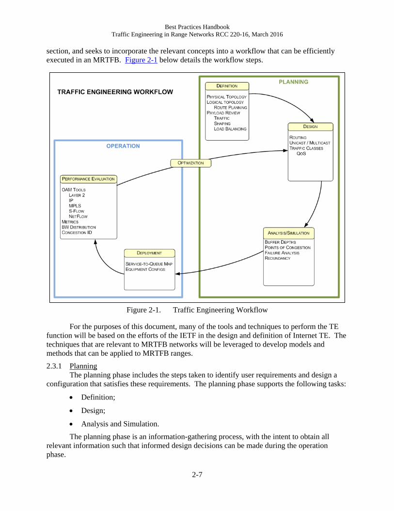
section, and seeks to incorporate the relevant concepts into a workflow that can be efficiently
executed in an MRTFB. Figure 2-1 below details the workflow steps.
Figure 2-1. Traffic Engineering Workflow
For the purposes of this document, many of the tools and techniques to perform the TE
function will be based on the efforts of the IETF in the design and definition of Internet TE. The
techniques that are relevant to MRTFB networks will be leveraged to develop models and
methods that can be applied to MRTFB ranges.
2.3.1 Planning
The planning phase includes the steps taken to identify user requirements and design a
configuration that satisfies these requirements. The planning phase supports the following tasks:
Definition;
Design;
Analysis and Simulation.
The planning phase is an information-gathering process, with the intent to obtain all
relevant information such that informed design decisions can be made during the operation
phase.
Best Practices Handbook
Traffic Engineering in Range Networks RCC 220-16, March 2016
2-8
2.3.1.1 Definition
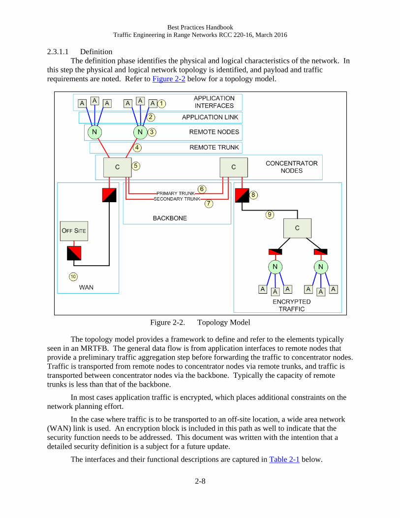
The definition phase identifies the physical and logical characteristics of the network. In
this step the physical and logical network topology is identified, and payload and traffic
requirements are noted. Refer to Figure 2-2 below for a topology model.
Figure 2-2. Topology Model
The topology model provides a framework to define and refer to the elements typically
seen in an MRTFB. The general data flow is from application interfaces to remote nodes that
provide a preliminary traffic aggregation step before forwarding the traffic to concentrator nodes.
Traffic is transported from remote nodes to concentrator nodes via remote trunks, and traffic is
transported between concentrator nodes via the backbone. Typically the capacity of remote
trunks is less than that of the backbone.
In most cases application traffic is encrypted, which places additional constraints on the
network planning effort.
In the case where traffic is to be transported to an off-site location, a wide area network
(WAN) link is used. An encryption block is included in this path as well to indicate that the
security function needs to be addressed. This document was written with the intention that a
detailed security definition is a subject for a future update.
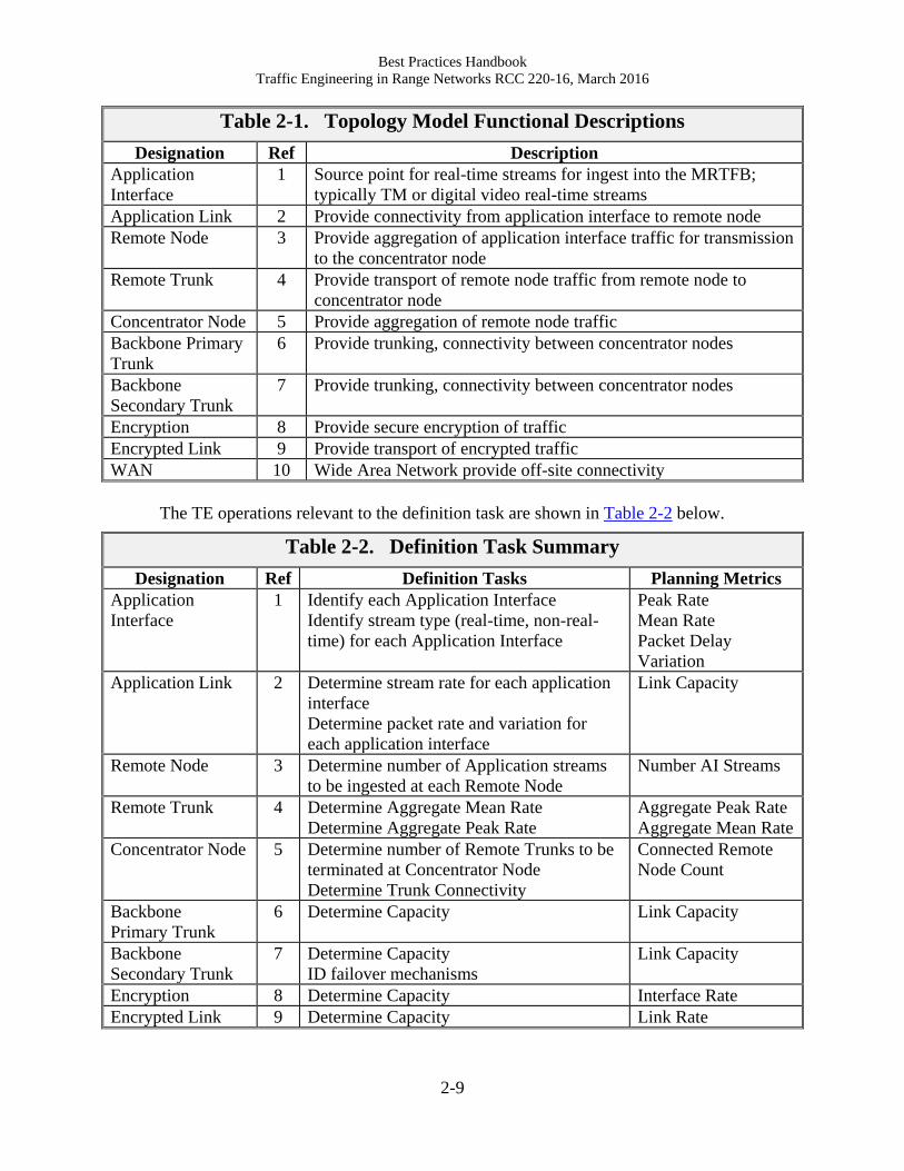
The interfaces and their functional descriptions are captured in Table 2-1 below.
Best Practices Handbook
Traffic Engineering in Range Networks RCC 220-16, March 2016
2-9
Table 2-1. Topology Model Functional Descriptions
Designation Ref Description
Application
Interface
1 Source point for real-time streams for ingest into the MRTFB;
typically TM or digital video real-time streams
Application Link 2 Provide connectivity from application interface to remote node
Remote Node 3 Provide aggregation of application interface traffic for transmission
to the concentrator node
Remote Trunk 4 Provide transport of remote node traffic from remote node to
concentrator node
Concentrator Node 5 Provide aggregation of remote node traffic
Backbone Primary
Trunk
6 Provide trunking, connectivity between concentrator nodes
Backbone
Secondary Trunk
7 Provide trunking, connectivity between concentrator nodes
Encryption 8 Provide secure encryption of traffic
Encrypted Link 9 Provide transport of encrypted traffic
WAN 10 Wide Area Network provide off-site connectivity
The TE operations relevant to the definition task are shown in Table 2-2 below.
Table 2-2. Definition Task Summary
Designation Ref Definition Tasks Planning Metrics
Application
Interface
1 Identify each Application Interface
Identify stream type (real-time, non-real-
time) for each Application Interface
Peak Rate
Mean Rate
Packet Delay
Variation
Application Link 2 Determine stream rate for each application
interface
Determine packet rate and variation for
each application interface
Link Capacity
Remote Node 3 Determine number of Application streams
to be ingested at each Remote Node
Number AI Streams
Remote Trunk 4 Determine Aggregate Mean Rate
Determine Aggregate Peak Rate
Aggregate Peak Rate
Aggregate Mean Rate
Concentrator Node 5 Determine number of Remote Trunks to be
terminated at Concentrator Node
Determine Trunk Connectivity
Connected Remote
Node Count
Backbone
Primary Trunk
6 Determine Capacity Link Capacity
Backbone
Secondary Trunk
7 Determine Capacity
ID failover mechanisms
Link Capacity
Encryption 8 Determine Capacity Interface Rate
Encrypted Link 9 Determine Capacity Link Rate

Best Practices Handbook
Traffic Engineering in Range Networks RCC 220-16, March 2016
2-10
WAN 10 Determine Capacity
Compatibility of TE Mechanisms
Aggregate Peak Rate
Aggregate Mean Rate
2.3.1.2 Design
The design task is the function where the physical topology and planning metrics
determined during the definition task are used to generate the detailed design of the network.
The major deliverables from this task are the equipment configurations that define the
functionality of the network elements. The TE operations relevant to the design task are shown
in Table 2-3 below.
Table 2-3. Design Task Summary
Designation Ref Design Tasks Planning Metrics
Application
Interface
1 Map streams into traffic classes to support
QoS
Map source streams into IP addresses
Traffic shaping, if supported
Traffic Classes
IP Address Scheme
Application Link 2 Capacity
Remote Node 3 Input queuing
Output Traffic shaping, if supported
Routing scheme
Multicast routing
Traffic Classes
IP Address Scheme
Remote Trunk 4 Capacity
Concentrator Node 5 Map streams into traffic classes
Input queuing
Routing scheme
Multicast routing
Traffic Classes
IP Address Scheme
Backbone
Primary Trunk
6 Capacity Link Capacity
Backbone
Secondary Trunk
7 Capacity
Redundancy mechanism
Link Capacity
Encryption 8 Capacity
Routing support <multicast>
Interface Rate
Encrypted Link 9 Capacity Link Rate
WAN 10 Capacity
Compatibility, Routing
Compatibility, QoS
Aggregate Peak Rate
Aggregate Mean Rate
2.3.1.3 Analysis and Simulation
The analysis and simulation task is an evaluation step where the performance of the
network is appraised based upon the configuration details generated in the design task. This is
the initial verification level of the network design.
The TE operations relevant to the analysis and simulation task are shown in Table 2-4
below.

Best Practices Handbook
Traffic Engineering in Range Networks RCC 220-16, March 2016
2-11
Table 2-4. Analysis and Design Task Summary
Designation Ref Analysis Tasks Metric
Application
Interface
1 Estimate mean, peak rate of each
application interface.
Peak Rate
Mean Rate
Packet Delay
Variation
Application Link 2 Estimate aggregate link rate
Estimate aggregate peak rate
Compare rates to link capacity
Link Capacity
Remote Node 3 Estimate aggregate rate, all Application
links
Estimate input buffer consumption
Estimate congestion, packet delay variation
Number AI Streams
Remote Trunk 4 Estimate of aggregate rate Aggregate Peak Rate
Aggregate Mean Rate
Concentrator Node 5 Estimate aggregate rate, all Remote links
Estimate input buffer consumption
Connected Remote
Node Count
Backbone
Primary Trunk
6 Prediction of alternate path during
congestion
Prediction of alternate path during failure
Link Capacity
Backbone
Secondary Trunk
7 Prediction of alternate path during
congestion
Prediction of alternate path during failure
Link Capacity
Encryption 8 Protocol support Interface Rate
Encrypted Link 9 Estimate of aggregate rate Link Rate
WAN 10 Estimate of aggregate rate
Protocol support, if gateway function
Aggregate Peak Rate
Aggregate Mean Rate
The main goal in this analysis is to identify potential faults due to congestion or lack of
link capacity. Capacity estimation is a straightforward process where the rate of the attached
equipment is estimated and accumulated to verify that the capacity of the aggregated links does
not exceed the capacity of the attached uplink.
Both analytical methods and simulation use a model-based approach where the network
topology, node behavior, and traffic statistics are modeled to provide predictions of traffic
behavior and identify any potential exposures to network outages. As in all model-based
approaches, care must be taken to ensure that the models accurately capture the operational
details of the actual network. Unfortunately, in many cases, the level of complexity to produce
an accurate network model quickly reaches a point where simplifications must be made in order
to make the analysis manageable. If the simplification exercise is not carefully managed the
output of the analysis/simulation may not accurately reflect the actual characteristics of the
operational network.

Best Practices Handbook
Traffic Engineering in Range Networks RCC 220-16, March 2016
2-12
2.3.2 Operation
The operation phase includes the actual deployment of the network design. Once the
actual network has been deployed the process of evaluating performance and optimization can
proceed. The operations phase supports the following tasks:
Deployment;
Performance Evaluation;
Optimization.
The intent of the operation phase is to construct a functional network that operates as
predicted in the definition and design phases.
2.3.2.1 Deployment
The deployment phase is where the equipment configurations developed in the design
phase and verified in the analysis and evaluation phase are applied to the end equipment.
The TE operations relevant to the deployment task are shown in Table 2-5 below.
Table 2-5. Deployment Task Summary
Designation Ref Deployment Tasks Metric / Ref
Application
Interface
1 Configure interface rates
Configure Layer 3, Layer 2 addresses
Peak Rate
Mean Rate
Packet Delay
Variation
Application Link 2 Configure L1 (Physical Layer) 10/100/1000BASE-T
Remote Node 3 Configure L3 Routing scheme
Configure multicast routing scheme
Number AI Streams
Remote Trunk 4 Configure L1 (Physical Layer) 10/100/1000BASE-T
Concentrator Node 5 Configure L3 Routing scheme
Configure multicast routing scheme
Connected Remote
Node Count
Backbone
Primary Trunk
6 Configure L1 (Physical Layer)
Configure L1 Optics
10/100/1000BASE-T
1000BASE-X
Backbone
Secondary Trunk
7 Configure L1 (Physical Layer)
Configure L1 Optics
Configure Redundancy
10/100/1000BASE-T
1000BASE-X
e.g., IEEE 802.1D
Encryption 8 Configuration of internal routing scheme Interface Rate
Encrypted Link 9 Link configuration, physical layer, as
required
Link Rate
WAN 10 Configuration of gateway functionality, as
required
Aggregate Peak Rate
Aggregate Mean Rate
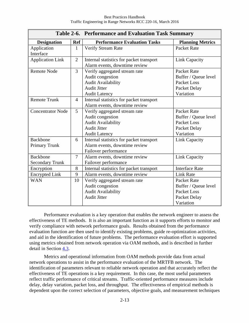
2.3.2.2 Performance Evaluation
Performance evaluation includes measurement of network operation and comparing
actual to planned performance. The TE operations relevant to the performance and evaluation
task are shown in Table 2-6 below.
Best Practices Handbook
Traffic Engineering in Range Networks RCC 220-16, March 2016
2-13
Table 2-6. Performance and Evaluation Task Summary
Designation Ref Performance Evaluation Tasks Planning Metrics
Application
Interface
1 Verify Stream Rate Packet Rate
Application Link 2 Internal statistics for packet transport
Alarm events, downtime review
Link Capacity
Remote Node 3 Verify aggregated stream rate
Audit congestion
Audit Availability
Audit Jitter
Audit Latency
Packet Rate
Buffer / Queue level
Packet Loss
Packet Delay
Variation
Remote Trunk 4 Internal statistics for packet transport
Alarm events, downtime review
Concentrator Node 5 Verify aggregated stream rate
Audit congestion
Audit Availability
Audit Jitter
Audit Latency
Packet Rate
Buffer / Queue level
Packet Loss
Packet Delay
Variation
Backbone
Primary Trunk
6 Internal statistics for packet transport
Alarm events, downtime review
Failover performance
Link Capacity
Backbone
Secondary Trunk
7 Alarm events, downtime review
Failover performance
Link Capacity
Encryption 8 Internal statistics for packet transport Interface Rate
Encrypted Link 9 Alarm events, downtime review Link Rate
WAN 10 Verify aggregated stream rate
Audit congestion
Audit Availability
Audit Jitter
Packet Rate
Buffer / Queue level
Packet Loss
Packet Delay
Variation
Performance evaluation is a key operation that enables the network engineer to assess the
effectiveness of TE methods. It is also an important function as it supports efforts to monitor and
verify compliance with network performance goals. Results obtained from the performance
evaluation function are then used to identify existing problems, guide re-optimization activities,
and aid in the identification of future problems. The performance evaluation effort is supported
using metrics obtained from network operation via OAM methods, and is described in further
detail in Section 4.3.
Metrics and operational information from OAM methods provide data from actual
network operations to assist in the performance evaluation of the MRTFB network. The
identification of parameters relevant to reliable network operation and that accurately reflect the
effectiveness of TE operations is a key requirement. In this case, the most useful parameters
reflect traffic performance of critical streams. Traffic-oriented performance measures include
delay, delay variation, packet loss, and throughput. The effectiveness of empirical methods is
dependent upon the correct selection of parameters, objective goals, and measurement techniques
Best Practices Handbook
Traffic Engineering in Range Networks RCC 220-16, March 2016
2-14
to ensure that the measured data is applicable in the network context and as an accurate
prediction of the effectiveness of TE efforts.
2.3.2.3 Optimization
Performance optimization defines a set of control functions that identify and mediate
conditions that can potentially degrade network performance. This task is driven by the results
from the performance and evaluation tasks. The main objective in this task is frequently the
identification and resolution of points of congestion in the deployed network.
Congestion is indicated by the presence of two events.
1. Excessive packet delay variation. Congestion is caused by the unavailability of network
resources; at the network equipment level, congestion occurs when several source packets
are competing for access to an egress port. As the egress port can only service one packet
at a time, the packets are placed in a buffer until the egress port becomes available. The
time spent in the buffer incurs delay in the packet transit through the equipment. This
additional delay and the variation in the delay are evidence that congestion is occurring.
In the case where packets can be buffered without loss the only impact is the delay and
delay variation induced in the latency at which the packet traverses the network.
2. Packet loss. In extreme cases, the contention for resources is so severe that, even with
packet buffering, packets are lost because the buffer cannot accommodate the number of
packets that cannot obtain access to the egress port.
Therefore in able to recognize and adequately respond to congestion, the packet delay
variation and loss metrics should be carefully monitored by the performance evaluation task.
Congestion can be addressed in a number of ways.
1. Increase capacity of egress interface.
2. Change service levels of traffic components.
3. Re-allocate traffic routes to remove traffic from congested paths to paths with excess
capacity.
4. Lower source rates of application traffic.
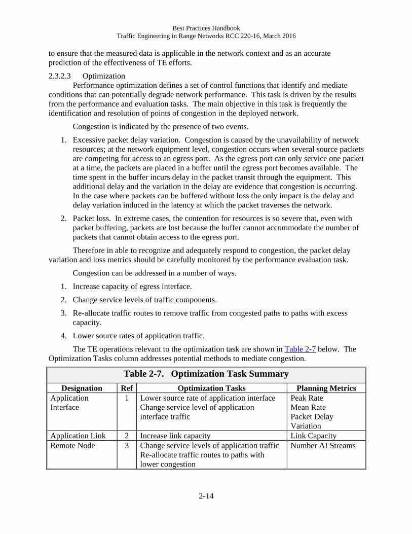
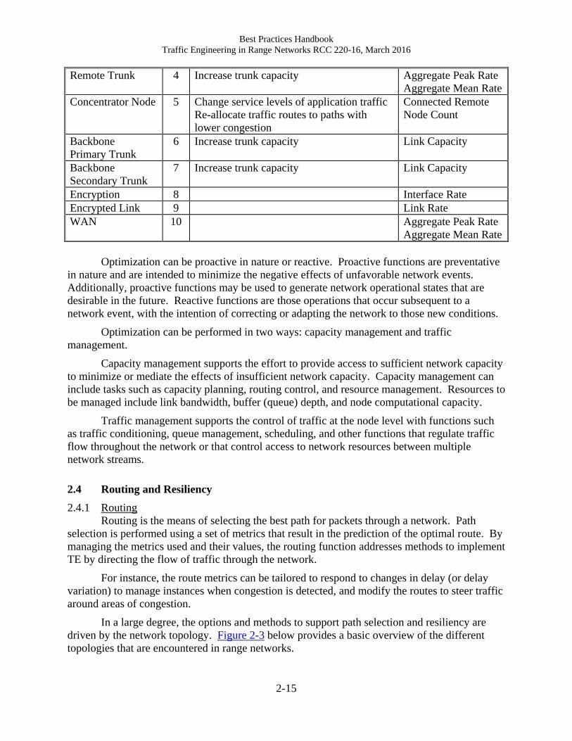
The TE operations relevant to the optimization task are shown in Table 2-7 below. The
Optimization Tasks column addresses potential methods to mediate congestion.
Table 2-7. Optimization Task Summary
Designation Ref Optimization Tasks Planning Metrics
Application
Interface
1 Lower source rate of application interface
Change service level of application
interface traffic
Peak Rate
Mean Rate
Packet Delay
Variation
Application Link 2 Increase link capacity Link Capacity
Remote Node 3 Change service levels of application traffic
Re-allocate traffic routes to paths with
lower congestion
Number AI Streams
Best Practices Handbook
Traffic Engineering in Range Networks RCC 220-16, March 2016
2-15
Remote Trunk 4 Increase trunk capacity Aggregate Peak Rate
Aggregate Mean Rate
Concentrator Node 5 Change service levels of application traffic
Re-allocate traffic routes to paths with
lower congestion
Connected Remote
Node Count
Backbone
Primary Trunk
6 Increase trunk capacity Link Capacity
Backbone
Secondary Trunk
7 Increase trunk capacity Link Capacity
Encryption 8 Interface Rate
Encrypted Link 9 Link Rate
WAN 10 Aggregate Peak Rate
Aggregate Mean Rate
Optimization can be proactive in nature or reactive. Proactive functions are preventative
in nature and are intended to minimize the negative effects of unfavorable network events.
Additionally, proactive functions may be used to generate network operational states that are
desirable in the future. Reactive functions are those operations that occur subsequent to a
network event, with the intention of correcting or adapting the network to those new conditions.
Optimization can be performed in two ways: capacity management and traffic
management.
Capacity management supports the effort to provide access to sufficient network capacity
to minimize or mediate the effects of insufficient network capacity. Capacity management can
include tasks such as capacity planning, routing control, and resource management. Resources to
be managed include link bandwidth, buffer (queue) depth, and node computational capacity.
Traffic management supports the control of traffic at the node level with functions such
as traffic conditioning, queue management, scheduling, and other functions that regulate traffic
flow throughout the network or that control access to network resources between multiple
network streams.
2.4 Routing and Resiliency
2.4.1 Routing
Routing is the means of selecting the best path for packets through a network. Path
selection is performed using a set of metrics that result in the prediction of the optimal route. By
managing the metrics used and their values, the routing function addresses methods to implement
TE by directing the flow of traffic through the network.
For instance, the route metrics can be tailored to respond to changes in delay (or delay
variation) to manage instances when congestion is detected, and modify the routes to steer traffic
around areas of congestion.
In a large degree, the options and methods to support path selection and resiliency are
driven by the network topology. Figure 2-3 below provides a basic overview of the different
topologies that are encountered in range networks.
Best Practices Handbook
Traffic Engineering in Range Networks RCC 220-16, March 2016
2-16
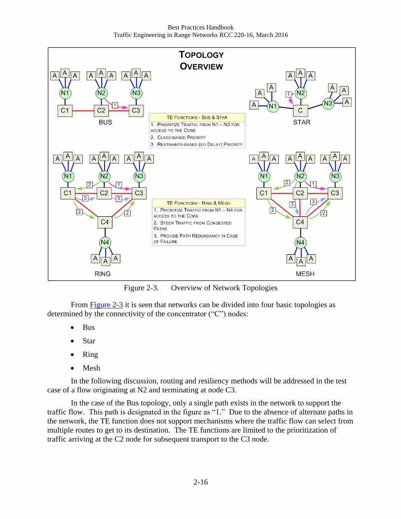
Figure 2-3. Overview of Network Topologies
From Figure 2-3 it is seen that networks can be divided into four basic topologies as
determined by the connectivity of the concentrator (“C”) nodes:
Bus
Star
Ring
Mesh
In the following discussion, routing and resiliency methods will be addressed in the test
case of a flow originating at N2 and terminating at node C3.
In the case of the Bus topology, only a single path exists in the network to support the
traffic flow. This path is designated in the figure as “1.” Due to the absence of alternate paths in
the network, the TE function does not support mechanisms where the traffic flow can select from
multiple routes to get to its destination. The TE functions are limited to the prioritization of
traffic arriving at the C2 node for subsequent transport to the C3 node.

Best Practices Handbook
Traffic Engineering in Range Networks RCC 220-16, March 2016
2-17
The case of the Star topology is the same as for the Bus topology: the lack of alternate
paths from the source to the destination limits the TE function to the prioritization and
transmission of traffic arriving and exiting from the concentrator node.
The Ring and Mesh topologies offer more complexity in that the topology introduces the
existence of multiple routes from the source to the destination nodes.
The Ring topology provides two paths for traffic to flow from node N2 to concentrator
node C3. These are labeled as “1” and “2” in Figure 2-3. If all links were of equal cost, then
Path 1 would be the preferred path for traffic flow. If the flow of traffic from node N1 to
concentrator node C3 is also considered, then one sees that this traffic can take two paths as well,
denoted “2” and “3” in the figure. If all links were of equal cost then the traffic could potentially
flow through path “3.” In this case the traffic from both node N1 and node N2 will flow through
the C2-C3 link. This link could become congested if the aggregate stream rates exceed the link
rate. The TE function will address this case to minimize congestion by routing the traffic to an
alternate path, in this case, path “2.”
The Mesh topology is an extension of the Ring topology, where multiple paths exist to
transport traffic from the source to the destination.
2.4.2 Resiliency
Resiliency is the method where the impact on packet delivery is minimized due to
outages in the network. The metrics to detect outages are packet loss and loss of connectivity.
In the cases discussed in Figure 2-3, it can be seen where the topology supports multiple
paths from a source to a destination that TE also functions to define secondary paths that can be
used in the case where the primary path fails.

Best Practices Handbook
Traffic Engineering in Range Networks RCC 220-16, March 2016
2-18
This page intentionally left blank.
Best Practices Handbook
Traffic Engineering in Range Networks, RCC 220-16, March 2016
3-1
CHAPTER 3
MRTFB Range Requirements
This chapter provides a description of key operational components of an MRTFB
network. A model is presented that defines end interfaces and application streams that are
frequently encountered on an MRTFB range.
3.1 Range Concept of Operations
In MRTFB ranges, the range architectural model is based on workflows frequently
encountered that support the acquisition, transport, management, and dissemination of real-time
information streams. These streams include the source TM and video streams that document the
results of range operations. In addition to these streams, a number of ancillary streams exist that
provide additional information about the range environment. Examples of these streams are
timing and metadata information. The goal is to efficiently acquire these streams and process
them to create a unified data set that describes all information in compatible formats. This
challenge produces a unique set of requirements in the information processing of range data.
Current range requirements include:
1. Remote acquisition of range TM and video sources;
2. Transport of TM and video sources from remote sites to central site;
3. Ingest and transport of metadata, time-correlated with TM and video sources;
4. Ingest of range timing information and insertion into range audio and video sources;
5. Storage and management of encoded TM and video streams;
6. Remote management of end equipment;
7. Editing, production, and archival of stream content;
8. Distribution and display of streams;
9. Support for security including transport through crypto and propagation through trusted
guards and gateways.
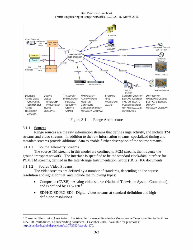
The workflow is divided into a number of architectural elements. Each element supports
a basic function that is encountered in the MRTFB environment. The MRTFB range architecture
model is shown in Figure 3-1.
Best Practices Handbook
Traffic Engineering in Range Networks RCC 220-16, March 2016
3-2
Figure 3-1. Range Architecture
3.1.1 Sources
Range sources are the raw information streams that define range activity, and include TM
streams and video streams. In addition to the raw information streams, specialized timing and
metadata streams provide additional data to enable further description of the source streams.
3.1.1.1 Source Telemetry Streams
The source TM streams in this model are confined to PCM streams that traverse the
ground transport network. The interface is specified to be the standard clock/data interface for
PCM TM streams, defined in the Inter-Range Instrumentation Group (IRIG) 106 documents.
3.1.1.2 Source Video Streams
The video streams are defined by a number of standards, depending on the source
resolution and signal format, and include the following types:
Composite (CVSB) - Analog video source (National Television System Committee),
and is defined by EIA-170.1
SDI/HD-SDI/3G-SDI - Digital video streams at standard-definition and high-
definition resolutions
1 Consumer Electronics Association. Electrical Performance Standards - Monochrome Television Studio Facilities.
EIA-170. Withdrawn, no superseding document 11 October 2004. Available for purchase at
http://standards.globalspec.com/std/773792/cea-eia-170.
Best Practices Handbook
Traffic Engineering in Range Networks RCC 220-16, March 2016
3-3
3.1.1.3 Source Timing Streams
Range timing is distributed via three methods.
IRIG. Timing distribution via IRIG is implemented as a serial stream containing
IRIG timing information.
NTP. Network Time Protocol (NTP) is a networking protocol for clock
synchronization over IP networks.
IEEE-1588. Precision Time Protocol (PTP) supports timing distribution across IP
networks at an accuracy superior to the NTP method.
3.1.1.4 Source Metadata Streams
3.1.1.4.1 Telemetry Metadata
The RCC defines two methodologies for the carriage of metadata information in
telemetry streams.
Legacy, or in-band metadata signaling, as defined by IRIG 106 Chapter 10,2 where
TM information as defined by the Telemetry Attributes Transfer Standard3 (TMATS)
is encoded into the PCM stream on Channel 0.
Out-of-band metadata signaling as defined in consisting of an extensible markup
language (XML) stream that defines the content and configuration of TM stream
sources.
3.1.1.4.2 Video Metadata
The video industry uses a different format based upon key-length-value encoding as
defined by standards from the SMPTE and the Motion Imagery Standards Board (MISB) that
define the dataset as well as the methodology for the insertion of metadata into compressed video
streams.
3.1.2 Coding
The coding function supports the conversion and multiplexing of the sources into streams
that can be carried by the transport infrastructure.
3.1.2.1 Telemetry Coding
Coding of TM data consists of the encapsulation of the PCM stream into a packetized IP
stream as defined by RCC Standard 218-10.4
2 Range Commanders Council. “Digital Recording Standard,” in Telemetry Standards. IRIG 106-15. June 2015.
May be superseded by update. Retrieved 2 February 2016. Available at
http://www.wsmr.army.mil/RCCsite/Documents/106-15_Telemetry_Standards/Chapter10.pdf 3 Range Commanders Council. “Telemetry Attributes Transfer Standard,” in Telemetry Standards. IRIG 106-15.
June 2015. May be superseded by update. Retrieved 2 February 2016. Available at
http://www.wsmr.army.mil/RCCsite/Documents/106-15_Telemetry_Standards/Chapter9.pdf. 4 Range Commanders Council. Telemetry Transmission Over Internet Protocol (TMoIP) Standard. RCC 218-10.
October 2010. May be superseded by update. Retrieved 27 May 2015. Available to RCC members with private
page access at https://wsdmext.wsmr.army.mil/site/rccpri/Publications/218-
10_Telemetry_Transmission_over_Internet_Protocol_(TMoIP)_Standard/.
Best Practices Handbook
Traffic Engineering in Range Networks RCC 220-16, March 2016
3-4
Two methods of metadata insertion into TM streams are identified as follows.
Legacy, or in-band metadata signaling, as defined by IRIG 106 Chapter 10, where
TM information as defined by the TMATS is encoded into the PCM stream on
Channel 0.
Out-of-band metadata signaling as defined in consisting of an XML stream that
defines the content and configuration of TM stream sources.
3.1.2.2 Video Coding
The coding technique for video sources includes compression of the video source along
with ingest of metadata and timing information where appropriate. Depending on the native
resolution, a video source can have a native bitrate of from 270 megabits per second (Mbps) to
2.97 gigabits per second. The compression operation reduces the encoded bitrate to 5 - 10 Mbps.
3.1.2.2.1 Video Metadata Insertion
The recommended method of metadata insertion is MISB 0604.2,5 synchronous method.
The use of the synchronous method ensures time correlation of metadata to the video content
when the metadata is extracted at the receive side of the network.
3.1.2.2.2 Telemetry Timing Insertion
Timing insertion into the coded TM streams enables real-time information to be added to
the source TM streams. Timing information can come from two sources:
IRIG supports legacy systems and supports local clock distribution;
IEEE-1588 supports network wide clock distribution.
3.1.2.2.3 Video Timing Insertion
Timing insertion into the encoded video stream provides time insertion to video streams.
Timing information can come from two sources:
Master Clock Source, using Global Positioning System reference;
NTP supports network wide clock distribution.
The video stream can have timing insertion performed in the following ways.
For composite video streams, timing is inserted in the vertical blanking interval.
Insertion of absolute date and time information is defined by the standard SMPTE
309:1999.6 This supports timing distribution between locally attached video streams.
5 Motion Imagery Standards Board. Time Stamping and Transport of Compressed Motion Imagery and Metadata.
MISB STD 0604.2. 9 June 2011. Superseded by MISB STD 0604.3. Retrieved 27 May 2015. Available at
http://www.gwg.nga.mil/misb/docs/standards/ST0604.2.pdf. 6 Society of Motion Picture & Television Engineers. For Television - Transmission of Date and Time Zone
Information in Binary Groups of Time and Control Code. ST 309:1999. May be superseded by update. Available
to SMPTE subscribers or for purchase at http://standards.smpte.org/content/978-1-61482-449-7/st-309-
1999/SEC1.body.pdf.
Best Practices Handbook
Traffic Engineering in Range Networks RCC 220-16, March 2016
3-5
For digital video streams, timing information is inserted in the vertical ancillary data
packet per standard MISB 605.3.7
For MPEG encoded streams, timing information is inserted into the program
elementary stream per MPEG standard ISO/IEC 13818.8
3.1.3 Transport
The transport infrastructure carries the video, audio, and ancillary streams that have been
generated by the encode functional block.
The video and audio streams are transported as multicast IP streams across the range
infrastructure. Multicast streams enable the following features:
Native support for “one-to-many” transport to allow multiple users simultaneous
access to a stream. This allows concurrent distribution, viewing, and archival of any
stream.
Efficient bandwidth utilization via Internet Group Management Protocol (IGMP)
signaling. Using IGMP signaling combined with IGMP-aware end equipment results
in the transport of streams only to end users that desire stream access, increasing the
efficiency of network bandwidth utilization.
Application of TE principles to provide reliable transport of the information streams.
3.1.4 Management
The management function provides the following features:
1. Monitoring of health and alarms of network connected elements;
2. Configuration of equipment;
3. Connection management.
3.1.5 Storage
The storage facility supports the capability to archive and retrieve data in non-real time.
The TM community has defined the storage requirements through IRIG 106 Chapter 10,
which has been discussed widely in the literature.
In the video community, a number of vendor-specific storage solutions exists that are
typically implemented using network-attached storage systems as the storage element.
7 Motion Imagery Standards Board. Inserting Time Stamps and Metadata in High Definition Uncompressed Video.
MISB STD 0605.3. 9 June 2011. Superseded by MISB STD 0605.5. Retrieved 27 May 2015. Available at
http://www.gwg.nga.mil/misb/docs/standards/ST0605.3.pdf. 8 International Telecommunications Union Telecommunication Standardization Sector). Information technology --
Generic coding of moving pictures and associated audio information: Systems. ITU-T Rec H.222.0 | ISO/IEC
13818-1:1996. n.d. Superseded by update. Available to ITU-T members and other subscribers at
http://www.itu.int/rec/T-REC-H.222.0-199611-S!Amd1-2/en.

Best Practices Handbook
Traffic Engineering in Range Networks RCC 220-16, March 2016
3-6
An important support component of the storage functional block is the media asset
manager, which supports annotation and cataloging and storage of the streams as they are
ingested into the storage subsystem. The video and audio streams can be categorized and
accessed by date and time, or by individual metadata tags, such as source ID, location, or
security level.
3.1.6 Content Creation
The content creation subsystem supports the retrieval, editing, and creation of content
based upon the video and audio assets captured into the storage subsystem.
Content creation supports the following features:
Creation of clips (subsections of source streams for later evaluation);
Time correlation clips to ensure that content from diverse sources is temporally
aligned;
Storage of final clips onto secondary storage assets (e.g., DVD).
3.1.7 Distribution
Distribution allows the range streams to be disseminated and viewed in a variety of user
endpoints. The distribution options described in this document support multi-user desktop
distribution as well as distribution and display on large displays for room viewing.
3.2 Telemetry System Overview
As the requirement in most MRTFB ranges is the reliable transport of TM streams via the
ground network, this section provides an overview description of TM systems. Included are the
major functions of a TM system and current methods for distribution of TM streams via the
MRTFB communications infrastructures.
As a process, TM is defined as the method of getting data from vehicles during
operational launches, test missions, and a variety of other applications. In this section, the
different segments that constitute a TM system are discussed. The segments of a generic TM
system are shown in Figure 3-2.
Best Practices Handbook
Traffic Engineering in Range Networks RCC 220-16, March 2016
3-7
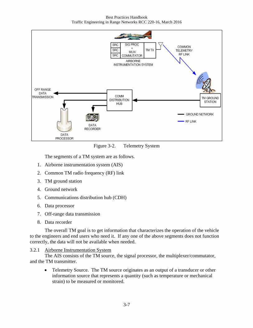
Figure 3-2. Telemetry System
The segments of a TM system are as follows.
1. Airborne instrumentation system (AIS)
2. Common TM radio frequency (RF) link
3. TM ground station
4. Ground network
5. Communications distribution hub (CDH)
6. Data processor
7. Off-range data transmission
8. Data recorder
The overall TM goal is to get information that characterizes the operation of the vehicle
to the engineers and end users who need it. If any one of the above segments does not function
correctly, the data will not be available when needed.
3.2.1 Airborne Instrumentation System
The AIS consists of the TM source, the signal processor, the multiplexer/commutator,
and the TM transmitter.
Telemetry Source. The TM source originates as an output of a transducer or other
information source that represents a quantity (such as temperature or mechanical
strain) to be measured or monitored.

Best Practices Handbook
Traffic Engineering in Range Networks RCC 220-16, March 2016
3-8
Signal Processor. The signal processor controls the relevant characteristics of the TM
source, such as amplitude, offset, and frequency, to allow interface compatibility with
downstream circuitry and to enhance signal integrity and quality.
Multiplexer/Commutator. The multiplexer/commutator function allows multiple TM
sources to be combined for transmission. The output is the combined information
that is generated by one or more individual information source(s) that have been
appropriately processed for optimal fidelity. The resulting composite TM source
signal is fed to the TM transmitter for transmission as an RF signal to the TM ground
station.
Telemetry Transmitter. The TM transmitter provides the functions required for RF
transmission and includes components such as the RF modulator, amplifier, and
antenna. The output of the TM transmitter is an RF signal that conveys the composite
TM source information to the ground for reception, demodulation, and transport to
the required end points.
3.2.2 Common Telemetry RF Link
The common TM RF link provides the connectivity from the AIS to the TM ground
station.
3.2.3 Telemetry Ground Station
The functional blocks at the TM ground station include the receiving antenna(s), TM
receiver(s), and demodulator(s) as required to regenerate the source TM streams. The source TM
streams, once they have been recovered from the RF link, are available for transport to the
various end stations as required over the ground network.
3.2.4 Ground Network
The ground network provides distribution of the TM streams from the TM ground station
to destinations that require them for analysis, storage, and monitoring. The ground network is
provided by the MRTFB infrastructure and is the functional area addressed in this document for
the TE effort.
3.2.5 Communications Distribution Hub
The TM ground station is connected to the CDH. The function of the CDH is to forward
the TM streams to the required end stations. The end stations can provide recording capability
(data recorder), analysis, and post-processing (data processor), or they can be off-range locations
(off-range data transmission).
3.2.6 Data Processor
The data processor supports processing of the TM data and includes functions such as bit
or frame synchronization, decryption/encryption, error correction algorithms, coding, and timing
functions along with data reduction algorithms.
3.2.7 Off-Range Data Transmission
The off-range data transmission facility allows the TM data to be transported to remote
locations for monitoring or additional processing.
The number of destination points that exist on the ground network and the potential
requirement to forward the TM stream to more than one destination point simultaneously
highlights the requirement to support multicast transmission of the TM streams over the ground

Best Practices Handbook
Traffic Engineering in Range Networks RCC 220-16, March 2016
3-9
network. The ability to natively support multicast traffic is one feature that makes IP transport of
TM streams very desirable.
3.2.8 Data Recorder
The data recorder provides the capability to record TM data in support of the mission
requirements to store and play back mission requirements.

Best Practices Handbook
Traffic Engineering in Range Networks RCC 220-16, March 2016
3-10
This page intentionally left blank.
Best Practices Handbook
Traffic Engineering in Range Networks, RCC 220-16, March 2016
4-1
CHAPTER 4
Performance
4.1 Test and OAM Mechanisms
As a means to support the optimization of the TE implementation, the ability to test the
performance of a range’s IP infrastructure is a key component of the TE effort. The results of
the performance evaluation task are used to verify the effectiveness of the TE implementation
and are used in the optimization task in cases where the TE implementation needs to be
improved by modifying the TE design.
As a result of efforts to provide testing and OAM in the IP community, a number of
mechanisms is currently in place that can be leveraged to provide the performance evaluation
task.
The test and OAM requirement defines two tasks: identification of parameters that
describe the health of the network, and definition of a measurement methodology. The following
sections address these two requirements.
4.2 OAM Metrics and Parameters
With the growth of the Internet has come the requirement for service providers to deliver
services with defined levels of quality. In the Internet model, providers deliver services with the
traffic specified by a number of QoS parameters. These parameters in aggregate define a
service-level agreement (SLA), which is a service definition and typically includes the following
parameters.
Mean Time Between Failures
Mean Time to Repair
Traffic Rates
Availability
While the concept of the SLA may not be readily apparent in the MRTFBs as the intent is
to leverage existing vendor implementations and standards in this effort, it is important to
understand the role of the SLA.
A key challenge is to provide a link between application-level requirements, such as
SLAs, and the network performance metrics (NPMs) that ultimately drive them. The NPMs are
defined at a lower level and include parameters such as:
Jitter;
Delay;
Throughput;
Connectivity;
Packet Loss;
Best Practices Handbook
Traffic Engineering in Range Networks RCC 220-16, March 2016
4-2
Congestion.
It is usually difficult to specify network-level QoS requirements at design or run-time. In
this document, the focus will be on MRTFB ranges as an enterprise network with enterprise
applications.
Another objective in the TE process is the mapping of NPMs to QoS parameters (SLAs)
and then giving the user the capability monitor these parameters in a useful way.
In the following example, an SLA requirement is mapped into a QoS parameter.
In a case where an application has a requirement to support a delay of less than 1 second,
it should be possible to collect the network state, defined by the following NPMs: traffic
congestion, throughput, availability, and latency.
As an example for the IP enterprise network, the SLA of some service provider with the
customer can be as follows: The availability over 99.99% should be assured. The average round-
trip time should be less than 50 milliseconds. The delivery ratio should be more than 98.0%.
The QoS network parameters would be in terms of availability, delay, jitter, latency, and
loss. Since the NPMs are gathered through network monitoring methods, a requirement exists to
convert these network statistics to QoS network parameters at the network management layer.
The QoS parameters then need to be mapped to the SLA at the application layer above.
4.3 OAM Methods
There is a number of methods that can be used to measure network performance and QoS
parameters; among them are active monitoring, passive monitoring, and through Simple Network
Management Protocol (SNMP) agents.
The active monitoring method obtains the current status of the network by setting up a
test node from the point that one wishes to measure, and then sending extra traffic from one
machine to another during a specific time. Typically loss, delay, and connectivity are the NPMs
that can be measured by active monitoring.
Passive monitoring can monitor the network status without additional traffic, but this
limits the NPMs that can be measured as compared to the active monitoring method. Utilization
and throughput are the NPMs that can be measured by passive monitoring.
By using SNMP agents, one can measure the status of the network device and obtain
network parameters that are supported by the network device. For example, Remote Monitoring
monitors traffic information with an SNMP agent. Functionality and throughput can be
measured using an SNMP agent.
Although NPMs can be obtained using these network monitoring methods, it is difficult
to apply these values to SLA parameters directly. To measure the SLA parameters, first the
NPMs for each SLA parameter should be decided. A QoS parameter can be mapped to one
NPM or many. This mapping depends on the type of services and can be very complicated.
Additionally, the QoS information should be presented in the form of SLA parameters, not
NPMs. Therefore, it is necessary to translate the measured NPMs to an SLA parameter. In this

Best Practices Handbook
Traffic Engineering in Range Networks RCC 220-16, March 2016
4-3
document, SLA is used interchangeably with QoS parameters at the application layer, and the
QoS parameters at the network level are used interchangeably with NPMs.
4.3.1 Standards-Based OAM Implementations
4.3.1.1 Ethernet OAM Mechanisms
As Ethernet emerged from being a local area network technology into a carrier-class
technology, industry has developed an OAM to ease the complexity of service provider
networks. Various standardization bodies developed standards for Ethernet OAM to operate at
different layers to address the requirements set forth by operators. Table 4-1 shows how the
OAM layers, their functions, and corresponding standards work to support the OAM
functionality. Standards that are not quoted in the body of this document are listed in the
References section of Appendix B. Those that do appear in the body are described in a footnote
at their first appearance and are listed in the Citations section of Appendix B.
Table 4-1. Ethernet Operations, Administration, and Maintenance Layers
OAM Layer Functions Standards
Transport Layer Ensures that two directly connected peers
maintain bidirectional communication.
Detects “link down” failure and notifies
higher layer.
Monitors link quality to ensure that
performance meets an acceptable level.
IEEE 802.3 (version 802.3ah
originally defined OAM link
fault management
mechanisms for EFM)
Connectivity
Layer
Monitors path between two non-adjacent
devices.
IEEE 802.1
ITU-T Y.1731
MEF Specification 17
Service Layer Produces metrics such as throughput,
roundtrip delay, and jitter that need to be
monitored to meet required SLAs.
ITU-T Y.1731
MEF Specification 17
Table 4-2 below lists the protocols that operate at the different OAM layers. In the
following sections, each protocol will be discussed in detail.
Table 4-2. Operations, Administration, and Maintenance Protocol Layers
OAM Layers Protocols
Transport Layer Link fault management
Connectivity
Layer
Connectivity fault management including linktrace, continuity check,
and loopback protocols
Service Layer Performance monitoring including frame loss, frame delay, and
throughput measurements
4.3.1.2 Link Fault Management
At the transport layer, link fault management (LFM) OAM mechanisms are used for
monitoring link operation for physical point-to-point Ethernet links connecting peer OAM
Best Practices Handbook
Traffic Engineering in Range Networks RCC 220-16, March 2016
4-4
entities. The Institute of Electrical and Electronics Engineers (IEEE) 802.39 standard defines
OAM mechanisms including keep-alives and loopbacks for LFM. Per IEEE 802.3, LFM
supports:
Remote failure indication during fault conditions;
Remote loopback mode used for fault isolation and link performance testing;
Link monitoring, which supports event notification and polling nodes.
4.3.1.2.1 Connectivity Fault Management
Complex implementations consisting of a number of interconnected bridged networks
pose a set of challenges to operators. It may not be possible to gain access to the entire network
because of the requirement to span multiple management domains, each with differing access
restrictions. Connectivity fault management (CFM) addresses these issues. Diverse
administrative domains perform CFM functions to detect, isolate, and correct connectivity faults
with minimum access to each other’s equipment. The CFM protocol operates at the connectivity
layer of OAM by monitoring paths between non-adjacent devices.
4.3.1.2.2 Performance Monitoring
The OAM processes that provide performance monitoring of Ethernet networks are
defined in Y.173110, which requires that OAM functions for performance monitoring allow
measurement of three parameters-frame loss ratio, frame delay, and frame delay variation. These
performance parameters apply to service frames that conform to an agreed-upon level of
bandwidth profile conformance. The IETF RFC 254411 document specifies throughput
measurement, which is an important component of performance monitoring.
In cases where the network implementation is based upon MPLS, a set of OAM
mechanisms supported by the MPLS protocol can be used.
4.3.1.3 MPLS OAM Mechanisms
The IETF is developing OAM mechanisms for fault detection and isolation in MPLS
networks. This includes OAM mechanisms for MPLS label-switched paths (LSPs) and
pseudowires (PWs). When an MPLS PW is transported over an MPLS LSP, OAM mechanisms
for the MPLS LSP can be used to detect failures in the data plane of the transit label-switched
routers (LSRs). In addition, MPLS PW OAM can be used to detect failures in the forwarding
plane on the egress of the MPLS PW. This verifies that the MPLS PW label is indeed present in
the MPLS forwarding table of the egress PE and is bound to the PW on which the ingress is
sending packets.
4.3.1.3.1 LSP Ping
When an LSP fails to deliver user traffic, the failure cannot always be detected by the
MPLS control plane. The LSP Ping is a tool that makes it possible to perform data plane fault
9 Institute of Electrical and Electronics Engineers. IEEE Standard for Ethernet. IEEE 802.3-2012. New York:
Institute of Electrical and Electronics Engineers. 10 International Telecommunications Union Telecommunication Standardization Sector. OAM Functions and
Mechanisms for Ethernet Based Networks. ITU-T G.8013/Y.1731. November 2013. Retrieved 25 June 2015.
Available at https://www.itu.int/rec/T-REC-G.8013-201311-I/en. 11 Internet Engineering Task Force. Benchmarking Methodology for Network Interconnect Devices. RFC 2544.
March 1999. Updated by RFC 6201 and RFC 6815. Retrieved 28 May 2015. Available at
http://tools.ietf.org/html/2544.
Best Practices Handbook
Traffic Engineering in Range Networks RCC 220-16, March 2016
4-5
detection and also verify the MPLS control plane against the data plane. It enables users to
detect traffic “black holes” or misrouting and provides a mechanism to isolate faults. The LSP
Ping is thematically equivalent to the ping (Internet Control Message Protocol echo request) that
is used for connectivity checks, and traceroute is used for hop-by-hop fault localization as well as
path tracing. The LSP Ping specifies a ping mode and a traceroute mode for testing MPLS LSPs.
4.3.1.3.2 LSP Traceroute
The LSP traceroute function provides OAM functionality for MPLS networks based on
RFC 4379.12 The LSP traceroute is used to isolate a data plane failure to a particular router and
to provide LSP path tracing.
With LSP traceroute, an echo request packet is sent to each transit LSR and the label
edge router (LER). The echo request follows the same data path that normal MPLS packets
would traverse. A transit LSR or an LER receiving the echo request checks that it is indeed a
transit LSR or LER for this path and returns echo replies.
4.3.1.3.3 Bidirectional Forwarding Detection
Bidirectional forwarding detection (BFD) provides a low-overhead short-duration
detection of failures in the path between adjacent forwarding engines, including the interfaces,
data link(s), and to the extent possible the forwarding engines themselves. In addition, BFD can
provide failure detection on any kind of path between systems, including virtual circuits and
tunnels (as long as there is some return path, of course). The BFD protocol can be used to detect
an MPLS LSP data plane failure. As described in the previous section, LSP Ping can be used to
detect MPLS data plane failures and verify the MPLS LSP data plane against the control plane.
The BFD protocol can be used for the former, but not for the latter; however, a combination of
LSP Ping and BFD can be used to provide faster data plane failure detection.
The preceding sections provide an overview of the mechanisms to support OAM for
Ethernet and MPLS topologies. This description is not complete but is intended to provide an
indication of the level of tools currently supported by equipment vendors.
From these descriptions, it is apparent that the bulk of the OAM mechanisms is intended
to support the detection and verification of network connectivity, while supplying limited
objective information regarding the state of the network.
4.3.2 Server-Based OAM Implementations
The implementation of a server-based OAM implementation seeks to address the
shortfalls of existing implementations by adding the capability of providing additional
information to the operator. This implementation uses a separate piece of hardware, the server,
to host the applications that perform OAM operations.
The server can host OAM software that provides additional information and statistics that
support the OAM function and the ability to monitor the performance of the network.
Two implementations to supply server-based OAM and performance monitoring
functions are sFlow and NetFlow.
12 Internet Engineering Task Force. Detecting Multi-Protocol Label Switched (MPLS) Data Plane Failures. RFC
4379. February 2006. Updated by RFC 5462, RFC 6424, RFC 6425, RFC 6426, RFC 6829, RFC 7506, and RFC
7537. Retrieved 27 May 2015. Available at http://tools.ietf.org/html/4379.
Best Practices Handbook
Traffic Engineering in Range Networks RCC 220-16, March 2016
4-6
4.3.2.1 sFlow
sFlow is a standards-based protocol that allows network traffic to be sampled at a user-
defined rate for the purpose of monitoring traffic flow patterns and identifying packet transfer
rates on user-specified interfaces.
sFlow provides the capability to perform traffic monitoring and supports techniques for
measuring network traffic and collecting and analyzing traffic data. sFlow uses packet sampling
to monitor network traffic, which is embedded in switches and routers. It allows the user to
continuously monitor traffic.
sFlow is a packet-sampling rather than a flow-sampling technology. An IP flow is
defined as a series of IP packets moving from a source to a destination through a particular port.
While technologies like NetFlow and J-Flow sample a part of each IP flow, sFlow samples 1 in
N of each packet passing through the interface, irrespective of the flow. Both random and time-
based sampling of packets and applications are carried out. While packet sampling might not
sample each flow, sFlow does provide results with quantifiable accuracy, especially with regards
to video streaming and other traffic-heavy applications.
When sFlow is enabled on a Layer 2 or Layer 3 switch, the system performs the
following sFlow-related tasks:
Samples traffic flows by copying packet header information;
Identifies ingress and egress interfaces for the sampled flows;
Combines sFlow samples into User Datagram Protocol (UDP) packets and forwards
them to the sFlow collectors for analysis;
Forwards byte and packet count data, or counter samples, to sFlow collectors.
sFlow exports traffic statistics to an external collector (sFlow collector). In this
implementation the external collector is hosted on the server, which will host an agent that
aggregates the statistics and forwards them to the network administration entity for analysis.
4.3.2.2 NetFlow
NetFlow is a protocol developed by Cisco Systems for collecting OAM information.
NetFlow functions similarly to sFlow, using packet sampling technology embedded in switches
and routers.
NetFlow is a sampling technology – it samples IP flows from a source to destination. An
IP flow is simply the flow of IP packets from a source interface to a destination interface across a
particular port. NetFlow uses a septuple key to identify unique flows - packets constituting a
flow share the same source and destination IP addresses and ports IP protocol, Ingress interface,
and Type of Service values.
The NetFlow-enabled device (router/switch) logs a new flow if a packet with unique
identifications in the 7-key values passes through its interface. Subsequent packets with the
same values are logged as increments to the same flow, while a difference in even one of the
values results in the termination of the current flow and the initiation of another flow. NetFlow
captures data for both ingress and egress IP packets in an interface.
The captured flow data is sent using UDP, as NetFlow records to a NetFlow collector.
The collector then analyzes the records to provide statistics on bandwidth usage, real-time and
Best Practices Handbook
Traffic Engineering in Range Networks RCC 220-16, March 2016
4-7
historical traffic patterns, application usage, and performance metrics. As in the sFlow instance,
the NetFlow collector is hosted on the server.
4.4 Vendor Case Studies
This section will present an overview of vendor implementations of end equipment that
supports the TE principles discussed earlier. The vendors identified provide equipment to
implement networks applicable to range applications. In general, range networks map into what
vendors designate in the merchant world as enterprise networks, so the equipment discussed is
what the vendors would deploy to fulfill requirements to implement an enterprise network.
A detailed hardware evaluation will not be presented in this document, as the speed of
hardware development will quickly make any information obsolete. Therefore a single instance
of equipment that supports the range network functions will be presented for each vendor.
Equipment descriptions will address the two functional blocks identified in the topology
presented in Figure 2-2:
1. Remote Nodes. The remote nodes aggregate application traffic for transport and entry to
the network core. In the merchant market this function is typically designated by the
following products:
Aggregation Switch;
Edge Switch;
Aggregation Router;
Edge Router.
2. Concentrator Nodes. The concentrator nodes aggregate the traffic from the remote nodes
and comprise the network core. In the merchant market this function typically carries the
following product designations:
Core Router;
Service Provider Router.
For each of the node functions one product series for each vendor will be identified.
4.4.1 Vendor 1 (Cisco)
4.4.1.1 Remote Node
ASR 1000 – The ASR 1000 Series Aggregation Services Router defines a product line
that is intended to address the aggregation of multiple real-time and non-real-time services for
input to the network core. One of the unique features of the ASR 1000 is that the functionality is
based on a generic hardware device, the Cisco QuantumFlow Processor. Use of this processor
enables the integration of future protocol additions or enhancements via a software upgrade. The
potential downside risk is that future network growth or protocol complexity could exceed the
bandwidth of the processor, resulting in poor performance.
4.4.1.2 Concentrator Node
Catalyst 6500 – The Catalyst 6500 is a core switch that can be scaled to support different
requirements. The chassis is blade-based, allowing addition of interfaces, and performance is
defined by the Supervisor Engine module that is fitted into the chassis.
Best Practices Handbook
Traffic Engineering in Range Networks RCC 220-16, March 2016
4-8
4.4.1.3 Protocol Support
The Cisco products support the routing protocols currently in place to support TE both at
the IP and MPLS level.
4.4.1.4 Configuration
Switch and Router configuration in Cisco equipment is supported by the IOS software,
which provides a command line interface (CLI) to manage the equipment.
NetFlow is an embedded instrumentation within Cisco IOS software to characterize
network operation.
The MPLS-aware NetFlow is an extension of the NetFlow accounting feature that
provides highly granular traffic statistics for Cisco routers. It collects statistics on a per-flow
basis just as NetFlow does to provide a view of network operation and identify any potential
operational issues in the network.
4.4.2 Vendor 2 (Brocade)
4.4.2.1 Remote Node
The Brocade ICX Series supports the requirements generally required by the remote node
to aggregate application streams. The ICX is the top of the line of the Brocade edge switches
and provides the highest level of performance and resiliency.
4.4.2.2 Concentrator Node
The MLX Series of switching routers is Brocade’s equipment for Concentrator Node
applications. The MLX switching core consists of a network processor-based architecture
coupled with terabit-scale switch fabrics, and supports protocols from layer switching to MPLS.
The Brocade MLX Series includes the existing Brocade MLX Routers and new Brocade
MLXe Core Routers available in 4-slot, 8-slot, 16-slot, and 32-slot systems. Additionally, the
Brocade MLX Series features advanced redundant switch fabric architecture for very high
availability.
4.4.2.3 Protocol Support
The Brocade products support the protocols identified in this document to provide TE for
both IP and MPLS implementations. Protocol support is performed by purchasing software
licenses to enable advanced protocol features such as advanced routing support and encryption.
4.4.2.4 Configuration
Configuration of the Brocade equipment is performed using a CLI, accessed via Telnet,
secure shell, or serial console. The Brocade CLI enables an administrator to monitor and
manage individual switches, ports, and entire fabrics from a standard workstation.
Access is controlled by a switch-level password for each access level. The commands
available through the CLI are based on the user’s login role and the license keys used to unlock
certain features.
4.4.3 Vendor 3 (Juniper)
4.4.3.1 Remote Node
The Juniper EX Series Ethernet Switches support the requirement of the Remote Node
function. This product series provides a range of chassis and port options, allowing the user to
scale the equipment to requirements.

Best Practices Handbook
Traffic Engineering in Range Networks RCC 220-16, March 2016
4-9
4.4.3.2 Concentrator Node
The Juniper MX Series 3D Universal Edge Routers support the requirement of the
Concentrator Node function. This product series provides a range of chassis and port options,
allowing the user to scale the equipment to requirements.
4.4.3.3 Protocol Support
The Juniper products support the protocols identified in this document to provide TE for
both IP and MPLS implementations. Protocol support is performed by purchasing software
licenses to enable advanced protocol features such as advanced routing support and encryption.
4.4.3.4 Configuration
Switch and router configuration in Juniper equipment is supported by the JunOS
software, which provides a CLI to manage the equipment. Junos OS offers XML interfaces for
advanced scripting capabilities, and has been designed to configure the routing protocols that run
on the MX Series and the properties of its interfaces. After a software configuration is activated,
Junos OS has been designed to monitor the protocol traffic passing through the MX Series, as
well as troubleshoot protocol and network connectivity problems.

Best Practices Handbook
Traffic Engineering in Range Networks RCC 220-16, March 2016
4-10
This page intentionally left blank.
Best Practices Handbook
Traffic Engineering in Range Networks, RCC 220-16, March 2016
5-1
CHAPTER 5
Implementation
5.1 Tools
This section provides an overview of tools that are available to support the TE design
process. Many of the tools discussed have limitations, some of which are as follows.
1. Vendor-Specific. Most of the tools available provide planning support for a particular
vendor.
2. Capacity. The tools for performing and simulation use simplifying assumptions that do
not map into complex implementations due to the increase in computational complexity
that results when simulating larger networks.
3. Application. The simulation tools are constrained in the outputs provided. Many of the
tools allow the user to simulate basic connectivity by simulating the provision of routing
configurations, but do not simulate traffic flows to assist in the prediction of flow
capacity and the identification of potential congestion. Again, this is due to the
computation complexity incurred, especially as the network topology grows.
5.1.1 Network Planning and Simulation
5.1.1.1 GNS3
The GNS3 application enables the performance of the network to be simulated without
the requirement for dedicated network hardware such as routers or switches.
The software provides a graphical user interface (GUI) and support for Cisco routers and
switches. It allows the user to design and configure graphical networks. GNS3 can be used to
simulate Cisco and Juniper equipment, but does not support Brocade equipment.
In order to provide complete and accurate simulations, GNS3 actually uses the following
emulators to run the very same operating systems as in real networks:
Dynamips – a Cisco IOS emulator;
VirtualBox – desktop and server operating systems in addition to JunOS;
Demu – a generic open-source machine emulator that runs Cisco protocols.
To use GNS3, the user must provide a copy of the network operating system, such as IOS
for Cisco equipment or JunOS for Juniper equipment.
5.1.2 Management
5.1.2.1 Vendor Implementations
Each of the vendors identified earlier offers a suite of applications to support the need to
monitor network performance and manage configurations. In the following sections a number of
vendor applications is identified and discussed.
Best Practices Handbook
Traffic Engineering in Range Networks RCC 220-16, March 2016
5-2
5.1.2.1.1 Cisco
Cisco provides a wide range of applications to assist in the network management
function. One such application is Cisco Prime Performance Manager, which is a network
management solution that supports the design, provisioning, and management of range networks.
Cisco Prime Performance Manager uses a Web-based interface and supports the
capability to define user reports. The application supports performance measurement with the
ability to define user thresholds for performance alert generation. Additionally, the application
supports the generation of pre-packaged reports to characterize network performance.
5.1.2.1.2 Brocade
Brocade Network Advisor provides performance and historical data reporting to give
visibility into network performance. The interface can be customized to support Brocade devices
as well as third-party P-hosted devices. The entire Brocade product portfolio is supported by
Brocade Network Advisor.
In addition to performance monitoring, the application provides event management
functionality with the capability to generate custom event alerts.
5.1.2.1.3 Juniper
Junos Space consists of a network management platform for deep element management,
plug-n-play management applications for reducing costs and provisioning new services quickly,
and a programmable software development kit for network customization.
Junos Space is a GUI-based provisioning application that provides a single control point
to manage network operations including security, physical, and wired services. Junos supports
the functions of network and fault monitoring, in addition to management capabilities.
5.1.2.2 Network Operations Center-Based
In contrast to vendor-supplied management solutions, a semi-custom solution can be
deployed to provide these functions. The Network Operations Center (NOC)-based solution
consists of an external server that hosts off-the-shelf IT management software. The commercial
off-the-shelf (COTS) software uses SNMP signaling to communicate with the end equipment.
All of the vendors identified in this document support SNMP signaling.
Some COTS vendors that implement the SNMP management function are:
WhatsUp Gold;
OpenView;
SolarWinds.
Implementations based on the NOC model provide the advantage of not being tied to a
particular hardware vendor implementation. Additionally, this solution lends itself to
customization, as many of the IT management software vendors provide the capability to
customize the look and feel of the user interface, report generation, and in some cases,
configuration of the attached equipment, using the SNMP signaling protocol.
Best Practices Handbook
Traffic Engineering in Range Networks, RCC 220-16, March 2016
A-1
Definitions
This section provides definitions that are referenced in this document.
Bottleneck - A network element whose input traffic rate tends to be greater than its output rate.
Congestion - A state of a network resource in which the traffic incident on the resource exceeds
its output capacity over an interval of time.
Demand-based congestion management - A congestion management scheme that addresses
congestion problems by regulating or conditioning offered load.
Effective bandwidth - The minimum amount of bandwidth that can be assigned to a flow or
traffic aggregate in order to deliver 'acceptable service quality' to the flow or traffic
aggregate.
Metric - A parameter defined in terms of standard units of measurement.
Measurement Methodology - A repeatable measurement technique used to derive one or more
metrics of interest.
Network Survivability - The capability to provide a prescribed level of QoS for existing services
after a given number of failures occur within the network.
Performance measures - Metrics that provide quantitative or qualitative measures of the
performance of systems or subsystems of interest.
Performance Metric - A performance parameter defined in terms of standard units of
measurement.
Provisioning - The process of assigning or configuring network resources to meet certain
requests.
Supply-based congestion management - A congestion management scheme that provisions
additional network resources to address existing and/or anticipated congestion problems.
Traffic Engineering (TE) - The network engineering activity that identifies a methodology to
enable the range engineer to ensure reliable delivery of information streams throughout a
network.
Traffic flow - A stream of packets between two end-points that can be characterized in a certain
way. A micro-flow has a more specific definition: A micro-flow is a stream of packets
with the same source and destination addresses, source and destination ports, and
protocol ID.
Traffic monitoring - The process of observing traffic characteristics at a given point in a network
and collecting the traffic information for analysis and further action.
Traffic trunk - An aggregation of traffic flows belonging to the same class that are forwarded
through a common path. A traffic trunk may be characterized by an ingress and egress
node, and a set of attributes that determine its behavioral characteristics and requirements
from the network.

Best Practices Handbook
Traffic Engineering in Range Networks RCC 220-16, March 2016
A-2
This page intentionally left blank.
Best Practices Handbook
Traffic Engineering in Range Networks, RCC 220-16, March 2016
B-1
Citations
Consumer Electronics Association. Electrical Performance Standards - Monochrome Television
Studio Facilities. EIA-170. Withdrawn, no superseding document 11 October 2004.
Available for purchase at http://standards.globalspec.com/std/773792/cea-eia-170.
International Telecommunications Union Telecommunication Standardization Sector.
Information technology -- Generic coding of moving pictures and associated audio
information: Systems. ITU-T Rec H.222.0 | ISO/IEC 13818-1:1996. n.d. Superseded by
update. Available to ITU-T members and other subscribers at http://www.itu.int/rec/T-
REC-H.222.0-199611-S!Amd1-2/en.
———. OAM Functions and Mechanisms for Ethernet Based Networks. ITU-T
G.8013/Y.1731. November 2013. Retrieved 25 June 2015. Available at
https://www.itu.int/rec/T-REC-G.8013-201311-I/en.
Institute of Electrical and Electronics Engineers. IEEE Standard for Ethernet. IEEE 802.3-
2012. New York: Institute of Electrical and Electronics Engineers.
Internet Engineering Task Force. Benchmarking Methodology for Network Interconnect
Devices. RFC 2544. March 1999. Updated by RFC 6201 and RFC 6815. Retrieved 28
May 2015. Available at http://tools.ietf.org/html/2544.
———. Detecting Multi-Protocol Label Switched (MPLS) Data Plane Failures. RFC 4379.
February 2006. Updated by RFC 5462, RFC 6424, RFC 6425, RFC 6426, RFC 6829,
RFC 7506, and RFC 7537. Retrieved 27 May 2015. Available at
http://tools.ietf.org/html/4379.
Motion Imagery Standards Board. Inserting Time Stamps and Metadata in High Definition
Uncompressed Video. MISB STD 0605.3. 9 June 2011. Superseded by MISB STD
0605.5. Retrieved 27 May 2015. Available at
http://www.gwg.nga.mil/misb/docs/standards/ST0605.3.pdf.
———. Time Stamping and Transport of Compressed Motion Imagery and Metadata. MISB
STD 0604.2. 9 June 2011. Superseded by MISB STD 0604.3. Retrieved 27 May 2015.
Available at http://www.gwg.nga.mil/misb/docs/standards/ST0604.2.pdf.
Range Commanders Council. “Digital Recording Standard,” in Telemetry Standards. IRIG 106-
15. June 2015. May be superseded by update. Retrieved 2 February 2016. Available at
http://www.wsmr.army.mil/RCCsite/Documents/106-
15_Telemetry_Standards/Chapter_10.pdf.
———. “Telemetry Attributes Transfer Standard,” in Telemetry Standards. IRIG 106-15. June
2015. May be superseded by update. Retrieved 2 February 2016. Available at
http://www.wsmr.army.mil/RCCsite/Documents/106-
15_Telemetry_Standards/Chapter9.pdf.

Best Practices Handbook
Traffic Engineering in Range Networks RCC 220-16, March 2016
B-2
———. Telemetry Transmission over Internet Protocol (TMoIP) Standard. RCC 218-10.
October 2010. May be superseded by update. Retrieved 27 May 2015. Available to
RCC members with private page access at
https://wsdmext.wsmr.army.mil/site/rccpri/Publications/218-
10_Telemetry_Transmission_over_Internet_Protocol_(TMoIP)_Standard/.
Society of Motion Picture & Television Engineers. For Television - Transmission of Date and
Time Zone Information in Binary Groups of Time and Control Code. ST 309:1999. May
be superseded by update. Available to SMPTE subscribers or for purchase at
http://standards.smpte.org/content/978-1-61482-449-7/st-309-1999/SEC1.body.pdf.
Best Practices Handbook
Traffic Engineering in Range Networks, RCC 220-16, March 2016
C-1
References
Charles H. Jones, PhD. “IRIG 106 Chapter 10 vs. iNET packetization: data storage and
retrieval.” Paper presented during 48th International Telemetering Conference, San
Diego, CA. October 22-25, 2012.
Darr, T., J. Hamilton, R. Fernandes, and C. H. Jones. “Design considerations for XML-based
T&E standards.” Paper presented during 47th International Telemetering Conference,
Las Vegas, NV, October 24-27, 2011.
Institute of Electrical and Electronics Engineers. IEEE Standard for Local and Metropolitan
Area Networks-- Bridges and Bridged Networks. IEEE 802.1Q-2014. New York:
Institute of Electrical and Electronics Engineers.
Internet Engineering Task Force. An Overview of Operations, Administration, and Maintenance
(OAM) Data Plane Tools. 21 October 2013. Expired April 2014. Retrieved 27 May
2015. Available at https://tools.ietf.org/html/draft-ietf-opsawg-oam-overview-10.
———. An Overview of the IETF Network Management Standards. RFC 6632. June 2012.
May be superseded by update. Retrieved 27 May 2015. Available at
http://tools.ietf.org/html/6632.
———. An Overview of the Operations, Administration, and Maintenance (OAM) Toolset for
MPLS-Based Transport Networks. RFC 6669. July 2012. May be superseded by
update. Retrieved 27 May 2015. Available at http://tools.ietf.org/html/6669.
———. Guidelines for the Use of the “OAM” Acronym in the IETF. RFC 6291. June 2011.
May be superseded by update. Retrieved 27 May 2015. Available at
http://tools.ietf.org/html/6291.
———. Overview and Principles of Internet Traffic Engineering. RFC 3272. May 2002.
Updated by RFC 5462. Retrieved 27 May 2015. Available at
http://tools.ietf.org/html/3272.
———. Requirements for Operations, Administration, and Maintenance (OAM) in Transparent
Interconnection of Lots of Links (TRILL). RFC 6905. March 2013. May be superseded
by update. Retrieved 27 May 2015. Available at http://tools.ietf.org/html/6905.
———. Requirements for Support of Differentiated Services-Aware MPLS Traffic Engineering.
RFC 3564. July 2003. Updated by RFC 5462. Retrieved 27 May 2015. Available at
http://tools.ietf.org/html/3564.
———. The Reasons for Selecting a Single Solution for MPLS Transport Profile (MPLS-TP)
Operations, Administration, and Maintenance (OAM). RFC 6670. July 2012. Retrieved
25 June 2015. May be superseded by update. Available at http://tools.ietf.org/html/6670.
Best Practices Handbook
Traffic Engineering in Range Networks RCC 220-16, March 2016
C-2
Metro Ethernet Forum. Service OAM Requirements and Framework – Phase 1. Technical
Specification MEF 17. April 2007. May be superseded by update. Retrieved 25 June
2015. Available at
https://www.mef.net/Assets/Technical_Specifications/PDF/MEF_17.pdf.
Motion Imagery Standards Board. Motion Imagery Sensor Minimum Metadata Set. MISB STD
0902.1. 9 June 2010. Superseded by MISB STD 0902.4. Retrieved 27 May 2015.
Available at http://www.gwg.nga.mil/misb/docs/standards/ST0902.1.pdf.
———. Motion Imagery Standards Profile. MISP 5.1. 11 December 2008. Superseded by
MISP-2015-2. Retrieved 27 May 2015. Available at
http://www.gwg.nga.mil/misb/docs/misp/MISP51.pdf.
———. Security Metadata Universal and Local Sets for Digital Motion Imagery. MISB STD
0102.5. 9 December 2008. Superseded by MISB STD 0102.11. Retrieved 27 May
2015. Available at http://www.gwg.nga.mil/misb/docs/rp/RP0102.5.pdf.
———. UAS Datalink Local Metadata Set. MISB STD 0601.2. 29 October 2008. Superseded
by MISB STD 0601.8. Retrieved 27 May 2015. Available at
http://www.gwg.nga.mil/misb/docs/standards/ST0601.2.pdf.
Range Commanders Council. Telemetry Attributes Transfer Standard (TMATS) Handbook.
RCC 124-15. July 2015. May be superseded by update. Retrieved 8 July 2015.
Available at http://www.wsmr.army.mil/RCCsite/Documents/124-
15_TMATS_Handbook/.
Society of Motion Picture & Television Engineers. 1.5Gb/s Signal/Data Serial Interface. ST
292-1:2012. May be superseded by update. Available to SMPTE subscribers or for
purchase at http://standards.smpte.org/content/978-1-61482-676-7/st-292-1-
2012/SEC1.body.pdf.
———. 3 Gb/s Signal/Data Serial Interface. ST 424:2012. May be superseded by update.
Available to SMPTE subscribers or for purchase at
http://standards.smpte.org/content/978-1-61482-714-6/st-424-2012/SEC1.body.pdf.
———. Data Encoding Protocol Using Key-Length-Value. ST 336:2007. May be superseded
by update. Available to SMPTE subscribers or for purchase at
http://standards.smpte.org/content/978-1-61482-476-3/st-336-2007/SEC1.body.pdf+html.
———. For Television – SDTV1 Digital Signal/Data – Serial Digital Interface. ST 259:2008.
May be superseded by update. Available to SMPTE subscribers or for purchase at
http://standards.smpte.org/content/978-1-61482-407-7/st-259-2008/SEC1.body.pdf.

Best Practices Handbook
Traffic Engineering in Range Networks RCC 220-16, March 2016
C-3
* * * End of Document * * *