Best Practice Guidance for Effective Methane Drainage and Use … · 2.1 Objectives of mine gas...
108
Best Practice Guidance for Effective Methane Drainage and Use in Coal Mines Second edition December 2016
Transcript of Best Practice Guidance for Effective Methane Drainage and Use … · 2.1 Objectives of mine gas...

Best Practice Guidance for Effective Methane Drainage and Use in Coal Mines
Second edition December 2016
UN
ECEU
NITED
NATIO
NS
Best Practice Guidance for Effective M
ethane Drainage and U
se in Coal Mines

Best Practice Guidance for EffectiveMethane Drainage and Use in Coal Mines
ECE ENERGY SERIES No. 47
Second edition
December 2016
22
Note
The designations employed and the presentation of the material in this publication do not imply the expression of any opinion whatsoever on the part of the Secretariat of the United Nations concerning the legal status of any country, territory, city or area, or of its authorities, or concerning the delimitation of its frontiers or boundaries.
Mention of any firm, licensed process or commercial products does not imply endorsement by the United Nations.
ECE/ENERGY/105
UNITED NATIONS PUBLICATION
Sales No.: E.17.II.E.1ISBN: 978-92-1-117121-1
e-ISBN: 978-92-1-059946-7
ISSN: 1014-7225
Copyright © United Nations, 2016 All rights reserved worldwide

33
Contents
Foreword ................................................................................................................................................. 9
Acknowledgements ................................................................................................................................. 10
Acronyms and Abbreviations ................................................................................................................ 14
Glossary of Terms..................................................................................................................................... 16
Executive summary ................................................................................................................................ 19
Chapter 1. Introduction .......................................................................................................................... 25
Key messages ....................................................................................................................................................................................... 25
1.1 Objectives of this guidance document ............................................................................................................................ 25
1.2 The Issues ................................................................................................................................................................................... 25
1.3 Gas drainage, capture, utilisation, and abatement ..................................................................................................... 27
Chapter 2. Fundamentals of gas control ............................................................................................... 31
Key messages ........................................................................................................................................................................................ 31
2.1 Objectives of mine gas control ............................................................................................................................................ 31
2.2 Occurrence of gas hazards .................................................................................................................................................... 31
Ignition of explosive methane mixtures ..................................................................................................................................... 33
2.3 Reducing explosion risk ......................................................................................................................................................... 33
2.4 Regulatory and management principles ......................................................................................................................... 34
Effective safety regulatory framework ......................................................................................................................................... 34
Enforcement .......................................................................................................................................................................................... 34
Permissible gas concentrations for safe working conditions .............................................................................................. 34
Safe transport and utilisation of gas ............................................................................................................................................. 34
Regulations to reduce ignition risk ............................................................................................................................................... 35
Chapter 3. Occurrence, release, and prediction of gas emissions in coal mines ............................... 37
Key messages ........................................................................................................................................................................................ 37
3.1 Introduction ............................................................................................................................................................................... 37
3.2 Occurrence of gas in coal seams ......................................................................................................................................... 37
3.3 The gas release process .......................................................................................................................................................... 37
3.4 Relative gassiness of coal mines ......................................................................................................................................... 38
3.5 Understanding gas emission characteristics of coal mines ...................................................................................... 38
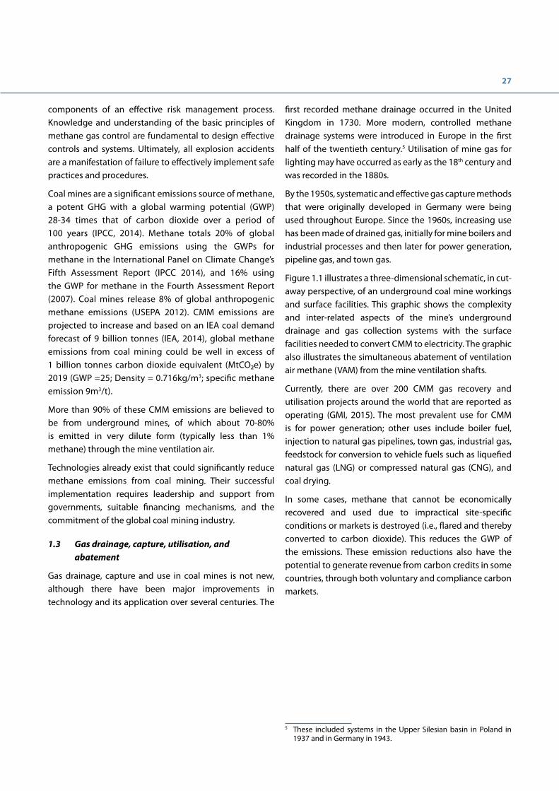
3.6 Measurement of the in situ gas content of coal ........................................................................................................... 39
3.7 Practical estimation of gas flows in coal mines ............................................................................................................. 40

4
Chapter 4. Mine ventilation .................................................................................................................... 43
Key messages ........................................................................................................................................................................................ 43
4.1 Ventilation challenges ........................................................................................................................................................... 43
4.2 Key ventilation design features ........................................................................................................................................... 43
4.3 Ventilation of gassy working faces .................................................................................................................................... 44
4.4 Ventilation system power requirement ............................................................................................................................ 46
4.5 Ventilation of coal headings ................................................................................................................................................. 46
4.6 Ventilation air flow monitoring .......................................................................................................................................... 47
4.7 Ventilation control .................................................................................................................................................................... 47
Chapter 5. Methane drainage ................................................................................................................ 49
Key messages ........................................................................................................................................................................................ 49
5.1 Methane drainage and its challenges ............................................................................................................................... 49
5.2 Basic principles of methane drainage practices employed worldwide ............................................................... 49
5.3 Predrainage basics .................................................................................................................................................................. 49
5.4 Postdrainage basics ................................................................................................................................................................ 51
5.5 Design considerations for methane drainage systems ............................................................................................... 52
5.6 Underground gas pipeline infrastructure ....................................................................................................................... 53
5.7 Monitoring of gas drainage systems ................................................................................................................................. 54
Chapter 6. Methane utilisation and abatement ................................................................................... 57
Key messages ........................................................................................................................................................................................ 57
6.1 Coal mine methane and climate change mitigation .................................................................................................. 57
6.2 Mine methane as an energy resource ............................................................................................................................... 57
6.2.1 Underground mine methane ................................................................................................................................. 58
6.2.2 Surface mine methane .............................................................................................................................................. 58
6.3 Use options ................................................................................................................................................................................. 59
6.4 Abatement and utilisation of drained methane ............................................................................................................ 60
6.4.1 Medium- to high-methane concentration CMM ............................................................................................. 60
6.4.2 Low-concentration drained methane ................................................................................................................. 61
6.4.3 Purification technologies for dilute methane from drainage systems .................................................... 61
6.4.4 Flaring ............................................................................................................................................................................. 62
6.5 Abatement or utilisation of low-concentration ventilation air methane (VAM) ............................................... 62
6.6 Methane monitoring ............................................................................................................................................................... 65
6.7 Use of methane from closed and abandoned mines .................................................................................................. 65

5
Chapter 7. Cost and economic issues .................................................................................................... 69
Key message .......................................................................................................................................................................................... 69
7.1 The business case for methane drainage ........................................................................................................................ 69
7.2 Comparative costs of methane drainage ........................................................................................................................ 69
7.3 Methane utilisation economics .......................................................................................................................................... 70
7.4 Carbon financing and other incentives ........................................................................................................................... 72
7.5 Opportunity cost of utilisation ............................................................................................................................................ 75
7.6 Environmental costs ................................................................................................................................................................ 75
Chapter 8. Conclusions and summary for policymakers ...................................................................... 77
Chapter 9. Case studies .......................................................................................................................... 81
Case study 1: Achieving planned coal production from a gassy, retreat longwall with severe strata stress and a spontaneous combustion prone coal seam – United Kingdom ............................................................................ 81
Case study 2: High performance longwall operations in areas with high gas emissions – Germany ................... 84
Case study 3: High performance longwall operations in areas with high gas emissions – Australia ................... 85
Case study 4: Safe mining of an outburst-prone coal seam – Australia .......................................................................... 86
Case study 5: Development of a CMM power co-generation/emission abatement scheme – China .................. 87
Case study 6: CMM utilisation and methane emissions mitigation at three large coal mines – China ................ 87
Case study 7: VAM – China................................................................................................................................................................ 91
Case study 8: VAM – Australia ........................................................................................................................................................ 92
Case Study 9: Reducing explosion risk in room-and-pillar mines – South Africa ......................................................... 93
Case study 10: Gas explosions at Pike River coal mine – New Zealand ........................................................................... 94
Appendix 1. Comparisons of gas drainage methods ........................................................................... 99
References ................................................................................................................................................ 103
Additional resources ............................................................................................................................... 105

6
List of Figures
Figure ES- 1 Distribution of CMM uses in global projects. This figure represents the total number of active CMM projects reported to GMI, based on type of end use. ............................................................................................................... 22
Figure 1.1 Schematic of an underground coal mine drainage system and surface facilities for energy recovery and abatement of CMM .................................................................................................................................................................................. 28
Figure 2.1 Formation of explosive mixtures ............................................................................................................................................ 32
Figure 3.1 Model section parallel to the longwall face showing the strata fractured as a result of removing the coal, thus forming the goaf and the output of a model showing the strata relaxation .................................................. 38
Figure 3.2 Gas content measurement equipment (Australian standard) ..................................................................................... 40
Figure 4.1 Airflows required for diluting longwall methane emissions to 2%, allowing for peaks ..................................... 44
Figure 4.2 Conventional U-type ventilation system ............................................................................................................................. 45
Figure 4.3 Ventilation layouts used on gassy longwall working faces ........................................................................................... 45
Figure 4.4 Example of ventilation air power requirement versus airflow ..................................................................................... 46
Figure 5.1 Schematic of premine drainage from lateral wells drilled from the surface ........................................................... 50
Figure 5.2 Various postdrainage drilling methods ................................................................................................................................ 52
Figure 6.1 Optimising energy recovery with near-zero methane emissions mining................................................................ 57
Figure 6.2 Cross-section through a strip mine showing possible placement of a directionally drilled borehole .......... 58
Figure 6.3 Cut –away drawing showing vertically drilled boreholes relative to planned expansion of an open pit coal mine ......................................................................................................................................................................................................... 59
Figure 6.4 Distribution of CMM project types worldwide .................................................................................................................. 60
Figure 6.5 Dürr VAM processing installation (3 RTO units) at the McElroy mine in the U.S. ................................................... 64
Figure 6.6 Dürr systems VAM installation at the Gaohe mine, China.............................................................................................. 65
Figure 6.7 Decline curve and gas reservoir potential for abandoned high gassy mine .......................................................... 66
Figure 7.1 CMM power generation and abatement: real-time performance monitoring showing the flow diagram and performance parameters of CMM used in three gas engines and one flare ..................................................... 71
Figure 7.2 Methane flow and purity fluctuations of drained CMM showing the optimised capacity and use of engines and flare ............................................................................................................................................................................................... 71
Figure 7.3 Dual revenues from CMM power generation: 40% gas captured, 80% used ......................................................... 74
Figure 9.1 Back-return system ...................................................................................................................................................................... 82
Figure 9.2 “Leapfrog” system ......................................................................................................................................................................... 82
Figure 9.3 Cross-measure drilling rig .......................................................................................................................................................... 83
7
Figure 9.4 Longwall with Y-shaped, advanced ventilation design and drainage boreholes in the roof and the floor behind the longwall ......................................................................................................................................................................................... 84
Figure 9.5 Mine layout plan showing ventilation and gas drainage systems .............................................................................. 85
Figure 9.6 CMM co-generation power plant phase 1 at mine D ...................................................................................................... 90
Figure 9.7 Flare system at mine T ................................................................................................................................................................. 90
Figure 9.8 VAM abatement and energy recovery implemented in China (Courtesy of Zhengzhou Mining Group, MEGTEC Systems and EcoCarbone) ............................................................................................................................................................ 91
Figure 9.9 VAM abatement and energy recovery for the generation of electricity ................................................................... 92
Figure 9.10 VAM processing and power generation plant WestVAMP ........................................................................................... 93
Figure 9.11 Surface installations reflect the environmental sensitivity of the area with buildings merging into the forest ......................................................................................................................................................................................................... 95
Figure 9.12 Fire at the upcast shaft following the third explosion .................................................................................................. 95
List of Tables
Table 1.1 Major coal mine explosion incidents, post-2010 ............................................................................................................... 26
Table 2.1 Selected examples of regulatory and advised flammable methane concentration limits .................................. 35
Table 6.1 Comparison of CMM uses ............................................................................................................................................................ 61
Table 7.1 Relative costs per tonne of coal produced in 2015 in US $ of various gas drainage methods ........................... 70
Table 9.1 List of case studies .......................................................................................................................................................................... 81
Table 9.2 Implementation schedule ........................................................................................................................................................... 88
Table 9.3 Summary of CMM project performance ................................................................................................................................ 89
Table 9.4 Amounts of energy that can be retrieved from an installation processing 250,000 Nm3/h of ventilation air under various conditions................................................................................................................................................................................ 91
Table 9.5 Assessment of ignition risk from methane layering in room-and-pillar mines ........................................................ 93


9
Foreword
Coal has been an important source of global primary energy production for the past two centuries, and will continue to be an essential component of the global energy mix for the next few decades. Without coal resources the UN development goals will not be achievable. This in no way diminishes the importance of renewable energy resources and other low carbon strategies, but does underscore a pragmatic recognition that, for the foreseeable future, coal is central to the energy security of many countries and will continue to play a significant role in ending energy poverty around the world.
Acknowledging that large-scale coal production will continue for some time, we must also recognize the continuing health, safety and environmental impacts of methane released during coal mining. Methane creates unsafe working conditions in many underground mines around the world, with human fatalities an unacceptable consequence of many methane-related accidents. Methane is also a greenhouse gas (GHG). Recent research has shown that the impact of methane on the atmosphere is more far reaching than was originally thought, and coal mines are the fourth largest source of methane emissions after the oil and gas, landfill and livestock industries.
During the transition from fossil fuels, it is vitally important to minimise the environmental impacts of coal production. Ensuring the safe extraction, transport, and use of methane throughout the coal mine life cycle are critical to this effort. Safe extraction of methane saves the lives of miners, and efficient use and destruction of the valuable gas provides an affordable but cleaner burning fuel for the communities that surround mining complexes. Technological advances have made it possible to significantly reduce methane emitted even from the gassiest mines. Yet deployment of these technologies and movement toward zero methane-related fatalities and lowered methane emissions to the atmosphere is not universal, and may be impeded by a lack of awareness of the guiding principles for methane drainage and use in coal mines. This document is intended to complement existing technical resources by providing accessible high-level guidance for senior corporate, government and financial decision-makers – all of whom play an integral role in decisions to implement best practices.
The Best Practice Guidance on Effective Methane Drainage and Use in Coal Mines fills a critical void. Recommended principles and standards on coal mine methane (CMM) capture and use are set out in a clear and succinct presentation to provide decision-makers with a solid base of understanding from which to direct policy and commercial decisions. Such knowledge is critical to achieve zero fatalities and explosions while minimising the environmental impact of CMM emissions.
The guidance document can also be used by students and technical specialists as an introduction to key methane management principles and references.
The Best Practice Guidance does not replace or supersede laws and regulations or other legally binding instruments, whether national or international. The principles outlined herein are intended to provide guidance to complement existing legal and regulatory frameworks and to support development of safer and more effective practices where industry practice and regulation continue to evolve. Although intended to support performance and principles based regulatory programmes, the Best Practice Guidance can also complement more prescriptive regulation and can support transition to performance-based regulation.
In the light of recent accidents and in memory of all the fatalities of the past, the authors of the 2010 and 2016 editions express the hope that their work will contribute to increasingly safer coal mining operations.
December 2016
Raymond C. Pilcher Chair, United Nations Economic Commission for Europe Group of Experts on Coal Mine Methane
Felicia A. Ruiz Co-Chair, Global Methane Initiative Coal Subcommittee

10
Acknowledgements
Sponsoring organizationsThe United Nations Economic Commission for Europe (UNECE) is one of the five UN Regional Commissions and provides a forum through which 56 countries of North America and Western, Central, and Eastern Europe as well as Central Asia come together to forge the tools of their economic cooperation. The main areas of UNECE’s activity are: economic cooperation and integration, environment policy, forests, housing and land, population, statistics, sustainable energy, trade, and transport. UNECE pursues its goals through policy analysis, the development of conventions, regulations and standards, and the provision of technical assistance (www.unece.org/energy/se/cmm.html). Energy related topics such as coal mining and coal mine methane are discussed by the member states in the Sustainable Energy Committee (SEC). The Group of Experts on Coal Mine Methane convenes as a subsidiary body of the SEC meeting regularly to discuss issues and promote best practices for management, capture and use of the methane gas liberated during the coal mining life cycle.
The Global Methane Initiative (GMI) is an international public-private partnership that works with government agencies around the world to facilitate project development in five key methane-producing sectors: agricultural operations, coal mines, municipal solid waste, oil and gas systems, and wastewater. Launched in 2004, GMI works in concert with other international agreements, including the United Nations’ Framework Convention on Climate Change, to reduce greenhouse gas (GHG) emissions. Unlike other GHGs, methane is the primary component of natural gas and can be converted to usable energy. The reduction of methane emissions therefore serves as a cost-effective method to reduce GHGs and increase energy security, enhance economic growth, improve air quality and improve worker safety. The Global Methane Initiative is comprised of 42 partner countries and the European Commission, representing about 70 percent of the world’s anthropogenic methane emissions. With respect to coal mine methane, GMI’s Coal Subcommittee brings together key experts in coal mine methane recovery and utilisation to share information about state-of-the-art technologies and practices through a number of workshops, trainings, study tours, and capacity-building initiatives (www.globalmethane.org).
StructureThe original document published in February 2010 was conceived by a Steering Committee, which provided direction and overall vision, and drafted by a Technical Experts Panel, consisting of five globally renowned experts in underground ventilation and methane drainage at coal mines. The draft document was first reviewed by a Stakeholders Advisory Group to ensure that messages were clear and effective for senior decision-makers, before undergoing a formal technical peer review process. The contributors to the original 2010 edition of the Best Practice Guidance and to this first revision of the 2010 document gave their time freely and willingly in the desire to promote increased safety in coal mining.
The 2016 update followed the process laid out above: an Executive Steering committee was formed by the Group of Experts and a Technical Experts Revision Drafting Group was formed of volunteers. Critical contributions were made by the Stakeholder Advisory Group who reviewed the document for content and adherence to the relevant principles being explained.
This first revision maintains the original structure, updates the content and provides additional case studies to broaden the range of best practice principles illustrated. More specifically, the revisions included in this printing comprise the following:
• Minor editorial changes and correction of a small number of typographical errors.
• Updated references where appropriate.
• Edits to existing subject matter that required additional explanation or examples to improve clarity.
• Addition of methane management at surface mines and abandoned underground mines.

11
• Updated costs for methane capture and use projects and revisions to the discussion on environmental commodity markets in light of changes to the markets for carbon offsets compared to 2010.
• Updates to existing cases studies and the addition of several new case studies.
• Updates to other text in the document with information on important advances that have transpired since 2010.
It is the intent of the UNECE and the GMI that this document be a “living” document that is periodically updated to reflect the dynamic environment in which the energy industry operates as well as the evolution of the global climate architecture.

12
Contributors to the second edition of the Best Practice Guidance for Effective Methane Drainage & Use in Coal Mines (October 2016)Executive Steering Committee
• Felicia A. Ruiz, Co-Chair, GMI Coal Subcommittee
• Clark Talkington, Vice Chair, Group of Experts on Coal Mine Methane
• Jacek Skiba, Vice Chair, Group of Experts on Coal Mine Methane
Technical Experts Revision Drafting Group• David Creedy, Sindicatum Sustainable Resources
• Raymond C. Pilcher, Raven Ridge Resources
• Michael Cote, Ruby Canyon Engineering
• Richard Mattus, RM Business Consulting
Stakeholder Advisory Group• Bharath Belle, Anglo American Metallurgical Coal (Australia/South Africa)
• Yuriy Bobrov, Association of Donbass Mining Towns (Ukraine)
• Martin Hahn, International Labour Organization
• Özgen Karacan, U.S. National Institute of Occupational Safety & Health
• Sergei Shumkov, Ministry of Energy (Russian Federation)
• Shekhar Saran, Central Mine Planning & Design Institute (India)
• Hu Yuhong, State Administration for Worker Safety (China)
• Bharath Belle, Anglo American Metallurgical Coal (Australia/South Africa)

13
Contributors to the original Best Practice Guidance for Effective Methane Drainage & Use in Coal Mines (February 2010)Executive Steering Committee
• Pamela Franklin, Co‐Chair, M2M Coal Subcommittee
• Roland Mader, Vice Chairman, UNECE Ad Hoc Group of Experts on Coal Mine Methane
• Raymond C. Pilcher, Chairman, UNECE Ad Hoc Group of Experts on Coal Mine Methane
• Carlotta Segre, Secretary, UNECE Ad Hoc Group of Experts on Coal Mine Methane
• Clark Talkington, Former Secretary, UNECE Ad Hoc Group of Experts on Coal Mine Methane
Technical Experts Drafting Group• Bharathe Belle, Anglo American
• David Creedy, Sindicatum Carbon Capital Ltd.
• Erwin Kunz, DMT GmbH & Co. KG
• Mike Pitts, Green Gas International
• Hilmar von Schoenfeldt, HVS Consulting
Stakeholder Advisory Group• Yuriy Bobrov, Association of Donbass Mining Towns (Ukraine)
• Graeme Hancock, World Bank
• Martin Hahn, International Labour Organization
• Hu Yuhong, State Administration for Worker Safety (China)
• Sergei Shumkov, Ministry of Energy (Russian Federation)
• Ashok Singh, Central Mine Planning & Design Institute (India)
• Luke Warren, World Coal Institute (United Kingdom)
Technical Peer Group• John Carras, Commonwealth Scientific and Industrial Research Organisation (Australia)
• Hua Guo, Commonwealth Scientific and Industrial Research Organisation (Australia)
• Li Guojun, Tiefa Coal Industry Ltd. (China)
• Glyn Pierce Jones, Trolex Ltd. (UK)
• B.N. Prasad, Central Mine Planning & Design Institute (India)
• Ralph Schlueter, DMT GmbH & Co. KG (Germany)
• Karl Schultz, Green Gas International (UK)
• Jacek Skiba, Central Mining Institute of Katowice (Poland)
• Trevor Stay, Anglo American Metallurgical Coal (Australia)
• Oleg Tailakov, International Coal and Methane Research Center, Uglemetan (Russian Federation)

14
Acronyms and Abbreviations
CBM Coalbed Methane
CDM Clean Development Mechanism
CERs Certified Emission Reductions
CFRR Catalytic Flow Reversal Reactors
CH4 Methane
CMM Coal Mine Methane
CMR Catalytic Monolith Reactor
CNG Compressed Natural Gas
CO2 Carbon Dioxide
CO2e Carbon Dioxide Equivalent
ERPA Emission Reduction Purchase Agreement
ERUs Emission Reduction Units
ESMAP Energy Sector Management Assistance Program (World Bank)
GHG Greenhouse Gas
GWP Global Warming Potential
IBRD International Bank for Reconstruction and Development
IC Internal Combustion
I&M Inspection and Maintenance
JI Joint Implementation
kWh Kilowatt-hour
LNG Liquefied Natural Gas
l/s Litres per Second
m Metre
m/s Metres per Second
m3/d Cubic Metres per Day
m3/s Cubic Metres per Second
mD Millidarcy (in common usage, equivalent to approximately 10-3 (µm)2)
MRD Medium Radius Drilling
MSA Molecular Sieve Adsorption
Mt Million (106) Tonnes
Mtpa Million Tonnes per Annum
MWe Megawatt of Electricity Capacity

15
Nm3 Normal Cubic Metres
PSA Pressure Swing Adsorption
scfm Standard Cubic Feet per Minute
t Tonne (metric) - equivalent to 1.102 short tons
t/d Tonnes per Day
TFRR Thermal Flow Reversal Reactor
TRD Tight Radius Drilling
UNECE United Nations Economic Commission for Europe
UNFCCC United Nations Framework Convention on Climate Change
VAM Ventilation Air Methane
VERs Verified Emission Reductions
USBM United States Bureau of Mines

16
Glossary of Terms
Within the coal and mine gas industry, there is still confusion over terms and abbreviations used within and across different jurisdictions. In addition to the terms listed here, the UNECE has prepared a Glossary of Coal Mine Methane Terms and Definitions that is more comprehensive and highlights how terminology is used in different regions. (www.unece.org/energy/se/pdfs/cmm/cmm4/ECE.ENERGY.GE.4.2008.3_e.pdf)
Air lock – an arrangement of doors that allows passage from one part of a mine ventilation circuit to another without causing a short-circuit.
Auxiliary ventilation – proportion of main ventilating current directed to the face of a blind heading (i.e., entry) by means of an auxiliary fan and ducting.
Back-return – a temporary ventilation arrangement formed at the return end of a U-ventilated longwall to divert a proportion of the air behind the face to allow access for gas drainage drilling and prevent high concentration goaf gases encroaching on the face end.
Bleeder shaft – a vertical shaft through which gas-laden air from working districts is discharged to the surface. Bleeder shafts are not typically man/material shafts.
Blind heading – a development roadway with a single entry that requires auxiliary ventilation.
Bord-and-pillar (room-and-pillar) – a method of mining in which coal is extracted from a series of headings, which are then interlinked leaving un-mined coal pillars to support the roof.
Capture (drainage) efficiency – the proportion of methane (by volume) captured in a methane drainage system relative to the total quantity of gas liberated. Gas liberated comprises the sum of drained gas plus gas emitted into the mine ventilation air. Usually expressed as a percentage, capture (or drainage) efficiency can be determined for a single longwall panel or for a whole mine.
Coal front gas – gas released from the working seam coalface by the action of the coal-cutting machine.
Coalbed methane (CBM) – a generic term for the methane-rich gas naturally occurring in coal seams typically comprising 80% to 95% methane with lower proportions of ethane, propane, nitrogen, and carbon dioxide. In common international use, this term refers to methane recovered from un-mined coal seams using surface boreholes.
Coal mine methane (CMM) – gas captured at a working coal mine by underground methane drainage techniques. The gas consists of a mixture of methane and other hydrocarbons and water vapour. It is often diluted with air and associated oxidation products due to unavoidable leakage of air into the gas drainage boreholes or galleries through mining induced fractures and also due to air leakage at imperfect joints in underground pipeline systems. Any gas captured underground, whether drained in advance of or after mining, and any gas drained from surface goaf wells is included in this definition. Pre-mining drained CMM can be of high purity and is considered CMM only when the well is mined through.
Extraneous gas – gas emissions not directly attributable to coal seam sources.
Gas drainage – methods for capturing the naturally occurring gas in coal seams to prevent it entering mine airways. The gas can be removed from coal seams in advance of mining using predrainage techniques and from coal seams disturbed by the extraction process using postdrainage techniques. Often referred to as Methane drainage if methane is the main gas component target to be captured. It is also referred to as mine degasification.
Goaf (United States: gob) – broken, permeable ground where coal has been extracted by longwall coal mining and the roof has been allowed to collapse, thus fracturing and de-stressing strata above and, to a lesser extent, below the seam being worked. The term gob is generally used in the United States; elsewhere, goaf is generally used.
17
Methane drainage – See Gas drainage.
Natural gas – typically refers to gas extracted from geological strata other than coal seams (i.e., from “conventional” gas reserves). The gas could be composed mostly of methane and may have originally migrated from coal seam sources.
Outburst – a violent ejection of coal or rock accompanied by large volumes of gas (methane, carbon dioxide or a mixture) from a freshly exposed face in a mining operation.
Predrainage (premine drainage) – extraction of gas from coal ahead of mining.
Postdrainage (postmine drainage) – extraction of gas released as a consequence of mining.
Respirable dust – microscopic particles of dust which can enter and damage the human lung.
Surface mine methane – methane contained in mineral deposits and surrounding strata that is released as a result of surface mining operations.
Ventilation air methane (VAM) – methane emitted from coal seams that enters the ventilation air and is exhausted from the ventilation shaft at a low concentration, typically in the range of 0.1% to 1.0% by volume.


Executive summary
The world has relied upon coal for a significant portion of its primary energy production since the Industrial Revolution. The global economy will be dependent on coal energy resources for the foreseeable future. Today, coal supplies around 30% of global primary energy, 40% of global electricity, and almost 70% of the world’s steel and aluminum industry. The International Energy Agency (IEA) projects a gradual slowing of global coal demand; however, emerging economies in Asia, in particular China and India continue to drive overall demand, which could reach 9 billion tonnes globally by 2019 despite China’s attempts to curb its reliance on coal (IEA, 2014). Global coal production in 2013 was 7.8 billion tonnes (World Coal Association).
With continued dependence on coal production, coal extraction is expected to become increasingly challenging in many parts of the world as shallow reserves are exhausted and deeper and more gassy seams are mined. Yet, societies are demanding and expecting safer mine working conditions, and greater environmental stewardship from the coal industry. The application of best practices for methane drainage and use is critical to reduce methane-related accidents and explosions that all too often accompany coal mining, while also contributing to environmental protection through reduction of greenhouse gas (GHG) emissions.
Coal mine methane poses safety and environmental challengesThe global coal industry, national governments, trade unions, and worker safety advocates are concerned that the frequency and severity of methane explosions, especially in emerging economies, are unacceptably high. Good mining practices need to be transferred to all countries to ensure that risks are managed professionally and effectively. No mine, even in the most developed countries, is free from safety risks. Regardless of location or mining conditions, it is possible to significantly reduce the risk of methane related incidents and explosions.
Methane is an explosive gas in the range of 5% to 15% methane in air. Its transport, collection, or use within this range, or indeed within a factor of safety of at least 2.5 times the lower explosive limit (2.0%) and at least two times the upper limit (30%), is generally considered unacceptable because of the inherent explosion risks.
Effective management of methane risks at coal mines can also have the benefit of contributing to reduced GHG emissions. Coal mines are a significant emissions source of methane, a potent GHG with a global warming potential (GWP) 28-34 times that of carbon dioxide (IPCC 2014). Methane totals 20% of global anthropogenic GHG emissions using the GWP for methane from the International Panel on Climate Change’s Fifth Assessment Report (IPCC 2014) and coal mines release 8% of global anthropogenic methane emissions (USEPA 2012). CMM emissions are projected to increase and based on the IEA coal demand estimate above, global methane emissions from coal mining could be well in excess of 1 billion tonnes carbon dioxide equivalent (MTCO₂e) by 2019 (GWP =25; Density = 0.716kg/m3; specific methane emission 9 m3/t).

20
Methane occurrence and control Methane-rich gases, generally containing 80% to 95% methane at underground mining depths, occur naturally in coal seams and are released as CMM when coal seams are disturbed by mining activities. CMM only becomes flammable and creates an explosion hazard when allowed to mix with air.
Emissions of large volumes of carbon dioxide also occur from coal mines in some geologic environments (e.g., Australia, South Africa, France, and Central and Eastern Europe), which can have important implications for overall mine degasification management strategies. Emissions of large volumes of methane, carbon dioxide or a mixture can accompany rapid ejections of rock or coal in an outburst event. The hazard may be compounded by secondary effects of explosion and asphyxiation. Systematic predrainage to reduce initial gas content can prevent such hazardous occurrences.
Good safety practice in coal mines is to reduce explosion risk by preventing the occurrence of explosive mixtures and, where practical, by monitoring and rapidly diluting explosive mixtures to safe concentrations (i.e., through ventilation systems) when abnormal levels of methane are detected. Where gas flows are so high that they exceed the capacity of the mine ventilation system to ensure adequate dilution of methane in the mine air, gas should be collected through a mine drainage system before it can enter the mine airways.
Good practice for mine methane drainage systems means both selection of a suitable gas capture method and proper implementation and execution of the mine drainage system. Following good practice will ensure that CMM can be safely captured, transported, and (if appropriate) utilised, at a concentration at least twice that of the upper explosive limit (i.e., at or over 30% methane).
Regulatory approaches to methane control A risk assessment approach to minimising explosion risks—combined with strong enforcement of robust ventilation and utilisation safety regulations—can improve mine safety and lead to substantially improved quantities and qualities of captured gas.
Furthermore, establishment and enforcement of safety regulations governing gas extraction, transport, and utilisation will encourage higher methane drainage standards, increased clean energy production, and greater emission reductions.
Prediction of underground methane releases Gas flows into underground coal mines under normal, steady-state conditions are relatively predictable in certain geological and mining conditions, although there may be significant variations from country to country. Lack of reliable gas emission prediction methods for deep- and multiple-seam mining continues to be a significant challenge due to the complex mining-induced interactions between strata, aquifers, and gas sources. Nonetheless, proven methods for projecting gas flows, gas capture, ventilation requirements, and utilisation potential are widely available and should be used routinely in mine planning.
By their very nature, unusual emission and outburst events are not easily predicted, but the conditions under which they can occur are reasonably well known. Therefore, following good practice allows for more effective management of these risks.
Mining activity can sometimes disturb adjacent natural gas reservoirs, leading to methane releases that can be as much as twice those expected from coal seam sources alone. Such situations can be identified at an early stage by comparing measured data and predicted results.
21
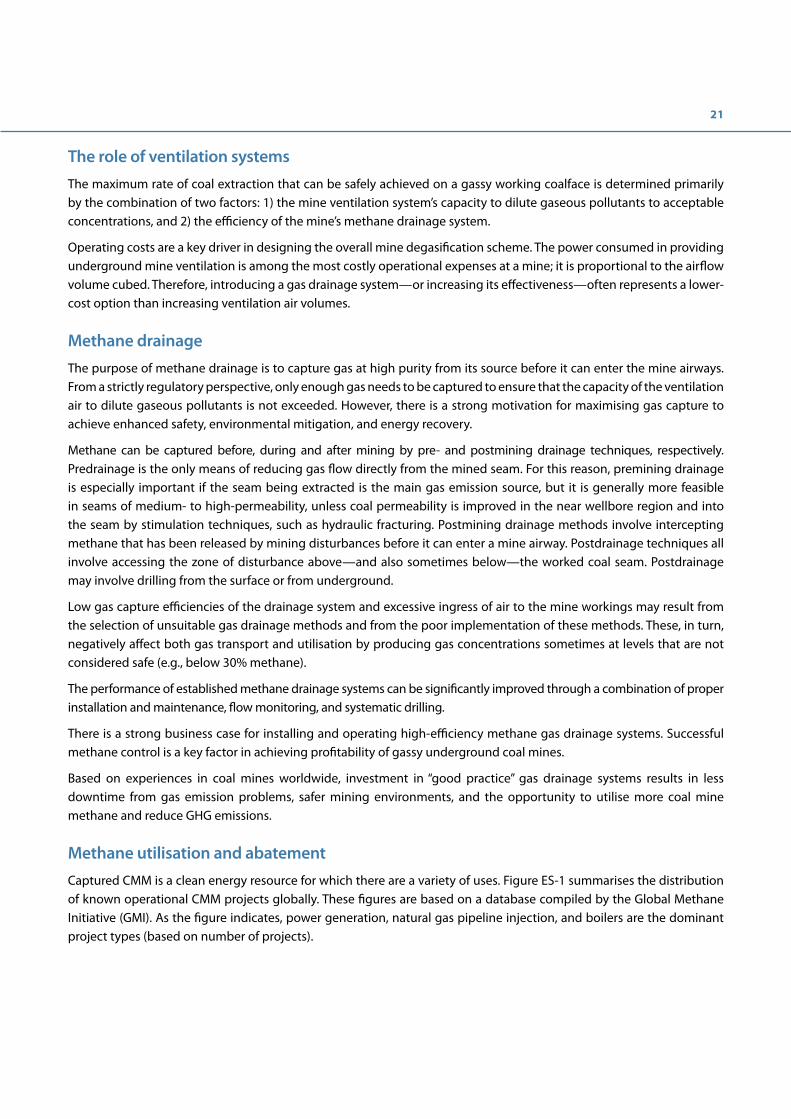
The role of ventilation systems The maximum rate of coal extraction that can be safely achieved on a gassy working coalface is determined primarily by the combination of two factors: 1) the mine ventilation system’s capacity to dilute gaseous pollutants to acceptable concentrations, and 2) the efficiency of the mine’s methane drainage system.
Operating costs are a key driver in designing the overall mine degasification scheme. The power consumed in providing underground mine ventilation is among the most costly operational expenses at a mine; it is proportional to the airflow volume cubed. Therefore, introducing a gas drainage system—or increasing its effectiveness—often represents a lower-cost option than increasing ventilation air volumes.
Methane drainage The purpose of methane drainage is to capture gas at high purity from its source before it can enter the mine airways. From a strictly regulatory perspective, only enough gas needs to be captured to ensure that the capacity of the ventilation air to dilute gaseous pollutants is not exceeded. However, there is a strong motivation for maximising gas capture to achieve enhanced safety, environmental mitigation, and energy recovery.
Methane can be captured before, during and after mining by pre- and postmining drainage techniques, respectively. Predrainage is the only means of reducing gas flow directly from the mined seam. For this reason, premining drainage is especially important if the seam being extracted is the main gas emission source, but it is generally more feasible in seams of medium- to high-permeability, unless coal permeability is improved in the near wellbore region and into the seam by stimulation techniques, such as hydraulic fracturing. Postmining drainage methods involve intercepting methane that has been released by mining disturbances before it can enter a mine airway. Postdrainage techniques all involve accessing the zone of disturbance above—and also sometimes below—the worked coal seam. Postdrainage may involve drilling from the surface or from underground.
Low gas capture efficiencies of the drainage system and excessive ingress of air to the mine workings may result from the selection of unsuitable gas drainage methods and from the poor implementation of these methods. These, in turn, negatively affect both gas transport and utilisation by producing gas concentrations sometimes at levels that are not considered safe (e.g., below 30% methane).
The performance of established methane drainage systems can be significantly improved through a combination of proper installation and maintenance, flow monitoring, and systematic drilling.
There is a strong business case for installing and operating high-efficiency methane gas drainage systems. Successful methane control is a key factor in achieving profitability of gassy underground coal mines.
Based on experiences in coal mines worldwide, investment in “good practice” gas drainage systems results in less downtime from gas emission problems, safer mining environments, and the opportunity to utilise more coal mine methane and reduce GHG emissions.
Methane utilisation and abatement Captured CMM is a clean energy resource for which there are a variety of uses. Figure ES-1 summarises the distribution of known operational CMM projects globally. These figures are based on a database compiled by the Global Methane Initiative (GMI). As the figure indicates, power generation, natural gas pipeline injection, and boilers are the dominant project types (based on number of projects).

22
Figure ES- 1 Distribution of CMM uses in global projects. This figure represents the total number of active CMM projects reported to GMI, based on type of end use.
(Source: Global Methane Initiative Coal Mine Methane Projects Database, August 2015).
Purification technologies have been developed and are extensively used (e.g., in the United States) to remove any contaminants from high-quality CMM—typically produced from predrainage—to meet stringent pipeline-quality standards (USEPA, 2009). For many other gas end-use applications, the high costs associated with purifying drained gas may be unnecessary and can be avoided by improving underground methane drainage standards.
With the proper equipment and procedures, unused drained gas can be safely flared to minimise GHG emissions. Flaring converts methane which has a GWP of 28-34 compared to carbon dioxide which has a GWP of one (IPCC, 2014).
Methane that is not captured by the drainage system is diluted in the mine ventilation air and is emitted to the atmosphere as dilute ventilation air methane (VAM), typically at methane concentrations of 1% or less. Despite this low concentration, collectively VAM is the single largest source of mine methane emissions globally. Thermal oxidation technologies have been introduced at demonstration and commercial scales at several sites globally (e.g., Australia, China, and the United States) to abate these emissions (and in two cases, to produce electricity from the dilute methane). Other technologies to mitigate VAM emissions (e.g., catalytic oxidation, lean fuel combustion, rotary kilns) are emerging and under development.
Cost and economic issues Effective gas drainage reduces the risks of gas outbursts, methane explosions, and hence accident risks. Reducing these risks in turn reduces their associated costs. Costs of methane-related accidents vary widely from country to country but are significant. For example, a 10% work stoppage or idling at a given mine due to a gas-related incident or accident could lead to US $8 million to US $16 million per year in lost revenues at a typical high-production longwall mine. Additional costs of a single fatal accident to a large mining operation could range from US $2 million to more than US $8 million through lost production, legal costs, compensation, punitive fines and even mine closure. In one case in the United States, a mining company paid $220 million in fines and penalties.1
1 Two recent examples are explosions at the Pike River Mine in New Zealand and the Upper Big Branch (UBB) mine in West Virginia, USA, both in 2010. The UBB mine suffered a catastrophic explosion in April 2010 resulting in loss of 29 lives and significant damage to the mine. The fallout from the accident has been significant. The mine was closed and permanently abandoned following the accident, and Massey Energy, one of the largest coal companies in the U.S. was broken up and its assets acquired by Alpha Natural Resources. Several former Massey executives have been convicted and sentenced to prison including Don Blankenship, the former CEO of the Massey Energy. Total fines and penalties amounted to US $220 million: a civil fine of $10.8 million from MSHA plus a $209 million Department of Justice settlement which included $46.5 million in restitution payments, $34.8 million in fines for safety citations, $48 million for a health and safety research and development trust fund, and $80 million for safety improvements during two years. The Pike River explosion occurred
37
16
30
102
11 13
3
0
20
40
60
80
100
120
Direct Thermal Flaring PipelineInjection
Power/CHP Town Gas VAM Vehicle Fuel,LNG, CNG
Num
ber o
f Pro
ject
s

23
At the same time, gas drainage creates an opportunity for gas recovery and utilisation. Such energy-recovery projects can be economical in their own right through sale of the gas or its conversion to electricity, vehicle fuel, or other valuable gas feed stocks.
Gas recovery and utilisation projects are increasingly also including revenue streams from carbon emission reduction credits in the form of Verified Emission Reductions (VERs), Certified Emission Reductions (CERs), or other credits such as emission reduction units (ERUs). These potential carbon financing options may be a critical factor in making some CMM utilisation projects economically viable that would be otherwise financially unattractive. In addition, carbon financing may provide the only revenue streams for abatement-only projects, such as VAM oxidation (without energy recovery) or CMM flaring.
VAM can also be used for power generation. At this time, VAM-derived power generation is not commercially feasible without carbon revenues or other incentives, such as preferential electricity pricing or portfolio standards.
Currently, investment decisions at most mines are likely to favour expansion in coal production rather than developing CMM utilisation projects (particularly power generation) due to the high opportunity cost of investing in power generation capital equipment and infrastructure. To meet environmental protection targets in the future, however, mine owners may be required to improve gas drainage performance beyond the level strictly required to meet the mines’ safety needs. Such improvements in the drainage system that yield relatively high-quality gas may provide an additional incentive for investment in gas recovery and utilisation projects.
Conclusions
A holistic approach to managing methane releases into coal mine workings and subsequent emissions into the atmosphere will have a number of beneficial impacts on overall mine safety, mine productivity, and environmental impacts, particularly with regard to GHG emissions.
• Global application of the accumulated knowledge on methane occurrence, prediction, control, and management that is currently available will improve mine safety. Implementation of good practices for methane drainage could substantially reduce explosion risks resulting from methane in coal mines.
• Emissions of methane, a potent GHG and energy resource, from underground coal mines can be significantly reduced by utilising the drained gas, flaring the gas that cannot be used, and mitigating VAM emissions by oxidation.
• There can also be a strong business case for exploiting and recovering energy from the captured gas because such systems will increase the availability of good-quality CMM.
in November 2010, also resulting in the death of 29 miners. A Royal Commission of Inquiry investigating the tragedy determined that the mine operator ran an unsafe mine and that regulation and inspection of the mine by the Department of Labour had failed to prevent the accident. The mine into which US $195 million had been sunk is now sealed and the area absorbed into a National Park. Pike River Coal went into receivership a few weeks after the incident; it was ordered to pay a fine of about US $0.5 million and a total of some US $3.2 million compensation to the victim’s families. No individual has been successfully prosecuted, five years after the incident.

Chapter 1. Introduction
Key messages Regardless of constraints, mine worker safety is paramount and should not be compromised.
A risk assessment approach to minimising explosion risks should be combined with strong enforcement of robust ventilation and utilisation safety regulations.
Ideally, modern coal mining companies recognise the benefits of adopting a holistic gas management system that constructively integrates underground gas control, methane utilisation, and reductions in greenhouse gas (GHG) emissions.
1.1 Objectives of this guidance document
This document aims to provide guidance to mine owners and operators, government regulators, and policymakers in the design and implementation of safe, effective methane capture and control in underground coal mines. It is intended primarily to encourage safer mining practices to reduce fatalities, injuries, and property losses associated with methane.
An important co-benefit of effective methane drainage at coal mines is to allow for the recovery of methane to optimise the use of otherwise-wasted energy resources. Thus, an important motivation behind the development of this guidance document is to facilitate and encourage the utilisation and abatement of coal mine methane (CMM) to reduce GHG emissions. Ultimately, incorporating these practices into a mine’s operating procedures will help to enhance the sustainability and long-term financial position of coal mines globally by:
• Striving to achieve a goal of zero fatalities, injuries, and property losses.
• Demonstrating the global coal industry’s commitment to mine safety, climate change mitigation, corporate social responsibility, and good citizenship.
• Establishing a global dialogue on CMM capture and use.
• Creating critical linkages among coal industry, government, and regulatory officials.
• Incorporating effective CMM capture as a part of an effective risk management portfolio.
This guidance document is intentionally “principles-based.” That is, it does not attempt to present a comprehensive, prescriptive approach that may not adequately account for site-specific conditions, geology, and mining practices. The authors recognise there is no universal solution and therefore, have established a broad set of principles that can be adapted as appropriate to individual circumstances. In general, the technologies for implementing these principles continue to evolve and improve over time. International industry best practices are outlined in this document as appropriate.
This document is not intended to serve as a comprehensive, detailed technical methane drainage manual. References and additional resources are provided at the end of this document and on the Coal Mine Methane page of the UNECE website2.
1.2 The Issues
Coal is an essential energy resource in both industrialised countries and emerging economies. Meeting the voracious energy demand, particularly in some rapidly-growing economies, has placed pressure on coal mines to increase their production—sometimes to levels beyond what can be safely sustained, leading to stresses on overall mining operations and compromising safety. The presence of methane in coal mines presents a serious safety concern that needs to be managed professionally and effectively. While methane explosions in underground coal mines are rare occurrences in many coal mining countries, they still cause thousands of mine fatalities and injuries every year.
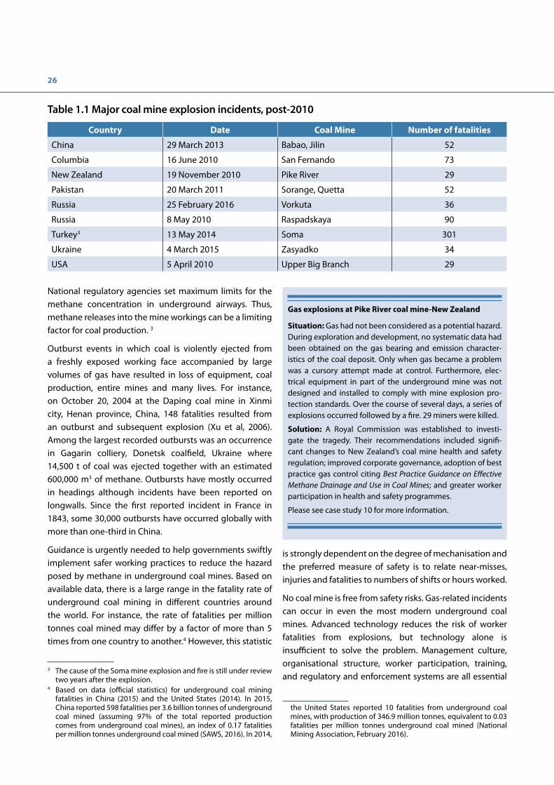
Many deaths can result from a single incident. Table 1.1 shows some of the most serious fatal coal mine explosions that have occurred in several countries since 2010. With effective management of mine methane, a central cause for such tragedies can be eliminated.
Accidents can occur when methane enters the mine space from the coal seam and surrounding strata as a result of the disturbance created by the mining operation. The amount of gas released into the mine is a function of both the rate of coal extraction and the in situ gas content of the coal and surrounding strata.
2 http://www.unece.org/energy/se/cmm.html
26
National regulatory agencies set maximum limits for the methane concentration in underground airways. Thus, methane releases into the mine workings can be a limiting factor for coal production. 3
Outburst events in which coal is violently ejected from a freshly exposed working face accompanied by large volumes of gas have resulted in loss of equipment, coal production, entire mines and many lives. For instance, on October 20, 2004 at the Daping coal mine in Xinmi city, Henan province, China, 148 fatalities resulted from an outburst and subsequent explosion (Xu et al, 2006). Among the largest recorded outbursts was an occurrence in Gagarin colliery, Donetsk coalfield, Ukraine where 14,500 t of coal was ejected together with an estimated 600,000 m3 of methane. Outbursts have mostly occurred in headings although incidents have been reported on longwalls. Since the first reported incident in France in 1843, some 30,000 outbursts have occurred globally with more than one-third in China.
Guidance is urgently needed to help governments swiftly implement safer working practices to reduce the hazard posed by methane in underground coal mines. Based on available data, there is a large range in the fatality rate of underground coal mining in different countries around the world. For instance, the rate of fatalities per million tonnes coal mined may differ by a factor of more than 5 times from one country to another.4 However, this statistic
3 The cause of the Soma mine explosion and fire is still under review two years after the explosion.
4 Based on data (official statistics) for underground coal mining fatalities in China (2015) and the United States (2014). In 2015, China reported 598 fatalities per 3.6 billion tonnes of underground coal mined (assuming 97% of the total reported production comes from underground coal mines), an index of 0.17 fatalities per million tonnes underground coal mined (SAWS, 2016). In 2014,
Table 1.1 Major coal mine explosion incidents, post-2010
Country Date Coal Mine Number of fatalities
China 29 March 2013 Babao, Jilin 52
Columbia 16 June 2010 San Fernando 73
New Zealand 19 November 2010 Pike River 29
Pakistan 20 March 2011 Sorange, Quetta 52
Russia 25 February 2016 Vorkuta 36
Russia 8 May 2010 Raspadskaya 90
Turkey3 13 May 2014 Soma 301
Ukraine 4 March 2015 Zasyadko 34
USA 5 April 2010 Upper Big Branch 29
is strongly dependent on the degree of mechanisation and the preferred measure of safety is to relate near-misses, injuries and fatalities to numbers of shifts or hours worked.
No coal mine is free from safety risks. Gas-related incidents can occur in even the most modern underground coal mines. Advanced technology reduces the risk of worker fatalities from explosions, but technology alone is insufficient to solve the problem. Management culture, organisational structure, worker participation, training, and regulatory and enforcement systems are all essential
the United States reported 10 fatalities from underground coal mines, with production of 346.9 million tonnes, equivalent to 0.03 fatalities per million tonnes underground coal mined (National Mining Association, February 2016).
Gas explosions at Pike River coal mine-New Zealand
Situation: Gas had not been considered as a potential hazard. During exploration and development, no systematic data had been obtained on the gas bearing and emission character-istics of the coal deposit. Only when gas became a problem was a cursory attempt made at control. Furthermore, elec-trical equipment in part of the underground mine was not designed and installed to comply with mine explosion pro-tection standards. Over the course of several days, a series of explosions occurred followed by a fire. 29 miners were killed.
Solution: A Royal Commission was established to investi-gate the tragedy. Their recommendations included signifi-cant changes to New Zealand’s coal mine health and safety regulation; improved corporate governance, adoption of best practice gas control citing Best Practice Guidance on Effective Methane Drainage and Use in Coal Mines; and greater worker participation in health and safety programmes.
Please see case study 10 for more information.
27
components of an effective risk management process. Knowledge and understanding of the basic principles of methane gas control are fundamental to design effective controls and systems. Ultimately, all explosion accidents are a manifestation of failure to effectively implement safe practices and procedures.
Coal mines are a significant emissions source of methane, a potent GHG with a global warming potential (GWP) 28-34 times that of carbon dioxide over a period of 100 years (IPCC, 2014). Methane totals 20% of global anthropogenic GHG emissions using the GWPs for methane in the International Panel on Climate Change’s Fifth Assessment Report (IPCC 2014), and 16% using the GWP for methane in the Fourth Assessment Report (2007). Coal mines release 8% of global anthropogenic methane emissions (USEPA 2012). CMM emissions are projected to increase and based on an IEA coal demand forecast of 9 billion tonnes (IEA, 2014), global methane emissions from coal mining could be well in excess of 1 billion tonnes carbon dioxide equivalent (MtCO₂e) by 2019 (GWP =25; Density = 0.716kg/m3; specific methane emission 9m3/t).
More than 90% of these CMM emissions are believed to be from underground mines, of which about 70-80% is emitted in very dilute form (typically less than 1% methane) through the mine ventilation air.
Technologies already exist that could significantly reduce methane emissions from coal mining. Their successful implementation requires leadership and support from governments, suitable financing mechanisms, and the commitment of the global coal mining industry.
1.3 Gas drainage, capture, utilisation, and abatement
Gas drainage, capture and use in coal mines is not new, although there have been major improvements in technology and its application over several centuries. The
5 These included systems in the Upper Silesian basin in Poland in 1937 and in Germany in 1943.
first recorded methane drainage occurred in the United Kingdom in 1730. More modern, controlled methane drainage systems were introduced in Europe in the first half of the twentieth century.5 Utilisation of mine gas for lighting may have occurred as early as the 18th century and was recorded in the 1880s.
By the 1950s, systematic and effective gas capture methods that were originally developed in Germany were being used throughout Europe. Since the 1960s, increasing use has been made of drained gas, initially for mine boilers and industrial processes and then later for power generation, pipeline gas, and town gas.
Figure 1.1 illustrates a three-dimensional schematic, in cut-away perspective, of an underground coal mine workings and surface facilities. This graphic shows the complexity and inter-related aspects of the mine’s underground drainage and gas collection systems with the surface facilities needed to convert CMM to electricity. The graphic also illustrates the simultaneous abatement of ventilation air methane (VAM) from the mine ventilation shafts.
Currently, there are over 200 CMM gas recovery and utilisation projects around the world that are reported as operating (GMI, 2015). The most prevalent use for CMM is for power generation; other uses include boiler fuel, injection to natural gas pipelines, town gas, industrial gas, feedstock for conversion to vehicle fuels such as liquefied natural gas (LNG) or compressed natural gas (CNG), and coal drying.
In some cases, methane that cannot be economically recovered and used due to impractical site-specific conditions or markets is destroyed (i.e., flared and thereby converted to carbon dioxide). This reduces the GWP of the emissions. These emission reductions also have the potential to generate revenue from carbon credits in some countries, through both voluntary and compliance carbon markets.
5 These included systems in the Upper Silesian basin in Poland in 1937 and in Germany in 1943.

28
Figure 1.1 Schematic of an underground coal mine drainage system and surface facilities for energy recovery and abatement of CMM
(Courtesy of Green Gas International)

29


Chapter 2. Fundamentals of gas control
Key messagesEstablishing and enforcing regulations for safe gas extraction, transport, and utilisation encourages higher methane drainage standards, as well as increased clean energy production and greater emission reductions.
There is tremendous global industry knowledge about and experience with managing methane explosion risks.
Safe working conditions in gassy mine environments cannot be achieved solely through legislation or even the most advanced technology. Rather, rational and effective management systems, management organisation, and management practices are fundamental to safe operations. Other critical elements of mine safety are appropriate education and training for both management and the workforce, and encouraging worker input as work safety practices are adopted and regularly reviewed.
2.1 Objectives of mine gas control
The primary aims of gas control systems are to prevent gas outbursts, methane explosions and asphyxiation risks in underground coal mines. In some coal mines, the methane released at an active longwall face can effectively be diluted below maximum permissible concentrations solely using ventilation techniques. However, if higher methane flows are expected from the working face, a combination of ventilation and methane drainage must be used. Employing best practice gas control will not only improve safety but will also enhance gas utilisation prospects.
Protection measures are available to reduce the propagation of an explosion after it has occurred and are important second lines of defence. Post-failure methane mitigation is, however, no substitute for prevention, which is the focus of these guidelines.
2.2 Occurrence of gas hazards
Methane-rich gases, generally containing between 80% and 95% methane, occur naturally in coal seams and are released upon disturbance by mining. Coal seam gas only becomes flammable and creates an explosion hazard when allowed to mix with air.
Emissions of large volumes of carbon dioxide are also encountered in coal mines in some geological
environments. Outbursts involving carbon dioxide occur in some countries and these are often more violent, more difficult to control and more dangerous than methane outbursts because of the greater sorption capacity of coal for carbon dioxide and also because of the toxicity of the gas. Carbon dioxide is heavier than air and toxic at concentrations above 5% in air, but physiological effects can be experienced at concentrations as low as 1%.
Methane is colourless, odourless, and tasteless; therefore, a measurement device is needed to confirm its presence. Methane is explosive when it is mixed with oxygen in a range of concentrations as shown in Figure 2.1.
At atmospheric pressure, the most explosive concentration of methane in air is 9.5% by volume. In the confined conditions underground, the maximum explosion pressure can increase as the unburned gas is compressed ahead of the flame front.
In oxygen-deprived environments, such as can occur in sealed goafs, explosive mixtures can only form if air is added. When present at higher concentrations, methane is an asphyxiant due to air displacement. As underground coal mines are confined, ignition of a substantial accumulation of methane invariably leads to an explosion.
Safe mining of an outburst-prone seam-Australia
Situation: In the 1990’s some Australian mines had been re-quired to prepare Outburst Management Plans (OMP). The procedures that were successful in high methane areas failed to produce positive results in some mines in high carbon diox-ide areas. Application of OMPs proved patchy and an outburst related fatality at Westcliff Colliery in 1994 highlighted the need for a more stringent approach.
Solution: The OMP must include a description of the respon-sibilities, procedures and protocols to facilitate safe working. The outburst management process involves analysis of seam gas content monitoring, geological structure and results of in-seam drilling. Gas drainage is the principal prevention mech-anism by reducing gas contents in the worked seam below a threshold concentration considered as the minimum to pose an outburst risk. Procedures for mining under outburst condi-tions are implemented when it becomes apparent that no fur-ther mitigation is possible or further drilling will not provide meaningful additional data.
Please see case study 4 for more information.

32
Methane has a tendency to stratify and form horizontal layers near the roof of mine workings where ventilation velocity is low. This phenomenon occurs because methane is lighter than air, with a density of only 0.55 that of air. In many instances, an air velocity of 0.5 metres per second (m/s) will prevent layering but there are some circumstances where this air velocity will be insufficient. Ventilation designers should be aware of variables that inhibit the layering of methane, such as layer width, inclination of roadway, gas emission rate, and airflow rate (Creedy & Phillips, 1997; Kissell, 2006).
In some circumstances, where mixing is not taking place due to insufficient air velocity, methane layers can form and flow either with or against the flow of the ventilation stream. These methane layers may propagate flame rapidly, thus increasing the risk and severity of explosions by providing a pathway between ignition sources and large accumulations of flammable mixtures (e.g., in longwall goafs). Once methane is mixed with air, however, it will not separate spontaneously. In any case, stratified layers of methane will have a composition transition from high methane percentage to low values passing though the explosive range. Therefore, it is important to prevent methane layering in especially active areas of the mines.
Mine operators actively isolate areas of mines that are no longer being worked (i.e., worked-out longwalls and
sometimes goafs of active longwalls) from the mine ventilation system by constructing barriers or seals. These ventilation barriers or seals are invariably imperfect due to ground movement and will not completely prevent gas emissions from entering into the active mine workings. Explosive gas mixtures can accumulate behind ventilation seals and will flow into airways as a result of ventilation fluctuations or falling barometric pressure.
Potentially high-risk areas in a coal mine—where coal seam methane passes through the explosive range—are in the goaf (gob) behind longwall faces, ineffectively ventilated areas and in the cutting zone of mechanised coal-cutting machines, and at ventilation stoppings. Explosive mixtures can also form within badly-designed or poorly-operated methane drainage systems due to excessive air being drawn in.
Room-and-pillar mine workings (with no pillar recovery) tend to disturb considerably lower volumes of adjacent strata than longwall methods; therefore, these mines tend to be less gassy than longwall mines. Room-and-pillar mines are not necessarily less at risk from explosions, however, due to the difficulties of achieving adequate ventilation of working faces. The predominant methane source in room-and-pillar workings is the worked seam itself. Layers of flammable gas mixtures can arise in the roof as a result of inadequate ventilation of blind headings and emissions from roof sources (see Case Study 9).
Figure 2.1 Formation of explosive mixtures
(Source: Moreby, 2009; based on Coward, 1928)

33
Ignition of explosive methane mixturesMethane-air mixtures can be ignited by a number of sources: electrical sparks, high temperatures caused by steel striking quartzitic rock, roof falls, aluminium impacting on iron, lightning strikes, smoking materials, explosives and detonators, spontaneous combustion, and naked flames.
The use of increasingly powerful rock- and coal-cutting machinery in modern coal mines has given rise to the serious problem of frictional ignitions when rock and minerals with the potential to produce high temperature sparks are struck by the cutting head. The high frequency of methane ignitions caused by rock- and coal-cutting tools compared to other sources indicates the technical difficulty in achieving absolute control of gas hazards.
2.3 Reducing explosion risk
Highlighting the underlying principles of explosion prevention is a major goal of this guidance. This knowledge is essential for effective programme design for controlling gas risks in coal mines. The principles described herein are synonymous with those embedded in the risk management systems that modern mining companies have implemented in striving towards zero accidents and zero explosions.
Management of coal mine gas explosion risks involves a large number of different activities (see Box 2.1), necessitating good organisation and clear allocation of responsibilities.
Reducing explosion risk by preventing the occurrence of explosive mixtures wherever possible—and taking measures to ensure separation of explosive mixtures from potential ignition sources—are the best safety practices in coal mines.
Controlling the dilution, dispersion, and distribution of flammable gases in coal mines to minimise the availability of fuel for ignition is critical. The risks associated with flammable gases in underground coal mines can be minimised in several ways: by diluting them to safe concentrations with ventilation air; by using proprietary devices to ventilate coal-cutting machines; by diverting gas away from working areas; and, where necessary, by capturing gas in boreholes or gas drainage galleries before it can enter mine airways.
The fundamental principles of reducing explosion risk are as follows:
Box 2.1 Typical coal mine gas explosion risk controls and procedures
• Use of flameproof electrical equipment and cables
• Control of explosives and their use below ground
• Provision of adequate fire and rescue facilities
• Gas drainage planning, design, and implementation
• Control of the discharge of drained methane gas
• Control of access to the mine and its working areas
• Restriction of contraband in the underground environment
• Inspection of underground workings
• Provision of anti-static materials
• Supervision of mining operations
• Use and maintenance of mechanical and electrical plant
• Provision for restricting the use of unsuitable equipment
• Supervision of mechanical and electrical operations
• Restriction of smoking materials below ground
• Gas management plan
• Outburst management plan
• Ventilation planning
• Control of the mine ventilation
• Monitoring and measurement of mine gas concentrations
• Use of auxiliary ventilation
• Degassing overlaying coal seams by the appropriate mining sequence
• Degassing of headings
• Frictional ignition precautions
• Use of the flame arrestors
• Provision of methane detectors
• Qualifications of employees
• Safety training
• Provision of explosion suppression barriers
• Posting of warning signs and notices
• Wherever possible, prevent occurrence of explosive gas mixtures (e.g., use of high-efficiency methane drainage methods, prevention and dispersal of methane layers by ventilation velocity).
• If explosive gas mixtures are unavoidable, minimise the volumes of explosive mixtures (e.g., rapid dilution in ventilation air to permissible methane concentrations).
• Separate unavoidable gas mixture occurrences from potential ignition sources (e.g., by using specially designed face-end ventilation systems to prevent gas accumulations near electric motors or avoiding use of electricity in longwall district return airways).

34
• Avoid ignition sources (e.g., unsafe electrical devices, naked flames, smoking).
• Control gas emissions from worked-out, sealed areas of the mine by using gas drainage methods regulated to maintain gas purity and by draining gas to accommodate fluctuations in barometric pressure.
2.4 Regulatory and management principles
Effective safety regulatory frameworkAn effective safety regulatory framework will provide coherent and clear guidance to the industry under the aegis of a lead safety authority, with clearly defined roles and responsibilities that do not overlap with those of other authorities.
Comprehensive coal mine gas safety regulations provide no guarantee of safe working conditions. To be effective, regulations must be understood, applied, and enforced by mine inspectors, mine management, supervisory staff, and mine workers. Proactive risk management and bottom-up safety responsibilities are the keys to prevention of gas accidents. Officials and miners can only be proactive if they understand the underlying principles of gas emission and control processes. Training and knowledge transfer are therefore necessary elements of a successful safety programme, as well as ready access to factual reports on gas incidents and their causes. Safety management and training should encompass both mine employees and contractors.
EnforcementEffective government inspectors audit mine safety conditions by conducting detailed underground inspections, providing expert guidance to mine management, reviewing the efficacy of regulations, and ensuring compliance with the regulations by working with mine operators to correct any deficiencies or penalise those who conspicuously ignore regulations and endanger life.
Effective safety and regulatory management systems also involve those who are most affected by failure to control gas, the miners themselves. All incidents, including near-misses, should be investigated and openly reported with the aim of improving safety performance and this is most effectively achieved in organisations in which workers are not penalised for reporting health and safety problems, i.e. a no-blame culture. To ensure the most effective risk
management within an organization, emphasis must be on accident or incident prevention.
Successful management of health and safety risks not only involves the regulatory authorities and the mine operator, but must include the mine workers as equal participants. As outlined in the International Labour Organisation’s Safety and Health in Mines Convention, 1995 (No. 176) and the Code of Practice on Safety & Health in Underground Coal Mines (ILO, 2006), workers are entitled to a safe working environment and participation, including the ability to report potential hazards without fear of retribution. Moreover, as partners in developing safe working conditions, workers are obligated to support safe working practices and maintain a safe mining environment.
Permissible gas concentrations for safe working conditionsPrescriptive regulations should be used sparingly, as they can stifle innovation, inhibit professional judgement, create a false sense of security and provide cover for poor decision-making. They are justified by physical imperatives such as the explosive range of flammable mine gases in air. All coal mining countries set upper limits of permissible methane or flammable gas concentrations that should not be exceeded in mine airways. Some apply different mandatory gas concentration limits in different parts of a coal mine depending on the activity and the risk of explosive levels being reached, and set minimum safe concentrations for transporting and using gas to minimise the risk of underground explosions (Table 2.1).
The precise action levels for gas concentrations by themselves are insufficient to ensure safe mine conditions. It is just as important to identify suitable locations at which the concentrations are measured, the procedures to be used for measurement, and the actions to be taken as a consequence of the measurements. Mining legislation in industrialised countries generally focuses on monitoring and control efforts in proportion to the degree of expected risk.
Safe transport and utilisation of gasTransport and use of explosive mixtures of gas is hazardous due to the dangers of propagating an explosion into the working areas of a mine. National mine safety regulations vary in their assessment of the minimum methane concentration considered safe for transport and utilisation, which varies from 25% to 40% among countries. A factor

35
Table 2.1 Selected examples of regulatory and advised flammable methane concentration limits
Limiting flammable methane
concentration [%]
Australia China Germany IndiahSouth
Africa
United
KingdomUSA Factors of
safetya
Maximum below which working is permitted in general
1.25 1.0 1.0 1.25 1.4 1.25 1.0 3.6 – 5.0
Maximum below which working is permitted in return airways
2.0b 1.5g 1.5 0.75 1.4 2.0b 2.0b 2.5 – 6.7
Minimum permitted for utilisation
nae nai 25 naf naf 40 25c 1.7 – 2.7
Minimum for underground pipeline transport
nae na 22 naf naf nae nad 1.5
(a) Factors of safety indicate the range of multiples below the lower explosive limit of 5% or above the upper explosive limit of 15% methane in air;
(b) If no electricity; (c) The United States handles methane degasification in the ventilation plan, there are no codes or regulations; (d) Not considered a problem as lower concentration goaf gases are generally drained at surface wells; (e) Determined by local risk assessment; (f ) Few or no applications so not addressed; (g) 2.5% for a non travelling return; (h) In India, methane standards are specified in Indian Coal Mine Regulation 1957, which is based on Mines Act 1952;(i) Ministry of Environmental Protection of People’s Republic of China & Central Administration of Quality Supervision, Inspection and
Quarantine of the People’s Republic of China: Emission Standard of Coalbed Methane/Coal Mine Gas (GB 21522-2008) requires that drained methane of 30% or higher is utilised but under certain conditions lower concentrations can also be used.
of safety of at least two times the upper explosive limit (i.e., 30% or greater methane concentration) is generally acknowledged as a good practice minimum.6 Accidents involving pipelines carrying methane at concentrations well above the upper flammable limit do not result in explosions because the gas is at too high a purity to burn; in these cases, a fire at the gas/air interface can be extinguished by fire-fighting techniques. In contrast, an ignition of low-purity gas (e.g., in the range of 5% to 15%) in a pipeline can cause the flame front to accelerate in both directions within the pipe, creating intense explosive forces and putting the entire mine in jeopardy.
Regulations to reduce ignition riskMost mining countries have regulations governing the type and use of materials permitted underground to
6 A factor of safety of at least 2.5 below the lower explosive limit of methane (i.e., below 2% methane) is a good practice maximum, in the absence of electricity; a higher factor of safety being necessary if electricity is in use.
minimise ignition risks. Not all potential ignition sources can be eliminated, however.
Electricity is needed to power mining equipment. Its safe use depends on the adoption of flame proofing and intrinsic safety standards, the use of armoured cables and safe connectors, and rigorous inspection and maintenance (I&M) procedures. Usually, regulations prohibit the use of electricity in specific roadways within a longwall district where elevated methane concentrations could arise, but still within permitted limits.
Frictional ignition risks on coal-cutting machines are minimised by using sharp cutting picks, properly positioned water sprays, and machine ventilation systems. Conveyors can also be an ignition source due to overheating of drive motors and rollers, but this risk can be substantially reduced through regular inspection and maintenance, and by elimination of coal dust and particles around heated components. Inappropriate human behaviour, such as lighting a cigarette underground, has been known to be a source of mine explosions.


Chapter 3. Occurrence, release, and prediction of gas emissions in coal mines Key messagesMethane gas flows into coal mines under normal, steady-state conditions are generally predictable.
Unusual emission and outburst events are not easily predicted, but the conditions under which they can occur are reasonably well-known. Detailed methods for reducing risks under these conditions have been developed and should be applied wherever significant risks are identified. In such circumstances, safe working conditions depend on the rigor of monitoring and implementation of gas control methods.
The importance of not only installing underground monitoring for operational mine safety reasons but gathering and using the data for safety planning cannot be overstated.
3.1 Introduction
Modern, high-production underground coal mines encounter increasingly high gas flows as their coal extraction rates increase, panel sizes expand and as they work deeper into potentially higher-gas content coal seams and into geologies with different gas sources. Longwall mining methods release substantially more gas than partial extraction methods such as room-and-pillar due to the large volume of strata disturbed by the caving process. Similarly, coal seams and other strata de-stress when overburden is removed during surface mining operations resulting in increased permeability and release of methane to the atmosphere. The volume of gas flow at surface mines is dependent on the amount of gas contained by the coal bearing strata and the rate of mining and de-watering. Though flows may be smaller at surface mines, significant volumes of gas may be liberated over time. Knowledge of the occurrence, emission characteristics, and expected gas flows from a coal mine as a function of the coal production rate is essential for safety, mine planning, ventilation, gas utilisation, and GHG emission control purposes. Other factors that influence gas production are mine design, geology, and operations.
3.2 Occurrence of gas in coal seams
The naturally-occurring gas found in coal seams consists mainly of methane (typically 80% to 95%) with lower proportions of heavier hydrocarbon gases, nitrogen, and carbon dioxide. The mixtures of methane, water vapour, air,
and associated oxidation products that are encountered in coal mines are often collectively termed “mine gas.”
Methane was formed in coal seams as a result of the chemical reactions taking place as the coal was buried at depth. Plant debris such as that found in modern swamps will slowly change from peat, organic detritus to coal, if the material becomes buried at a sufficient depth and remains covered for a length of time through a process known as coalification. The greater the temperature, pressure, and duration of coal burial, the higher the coal maturity (i.e., rank) and the greater the amount of gas generated. Much more gas was produced during this coalification process than is now found in the seams. The gas lost during the coalification process has been emitted as the gas bearing strata were exposed at ancient land surfaces, removed in solution by ground water passing through, or has migrated and been trapped in the pore spaces and structures in surrounding rocks. This gas may have accumulated in adjacent porous strata such as sandstones or may have been adsorbed by organic shale. These reservoir rocks can become significant sources of gas flows into the mine if the gas-bearing layers are sealed by surrounding impermeable strata and remain undisturbed until mining takes place. Methane is more concentrated in coal compared to any other rock type because of the adsorption process, which enables methane molecules to be packed on to the coal’s internal surface area to a density almost resembling that of a liquid. In a vertical sequence of coal seams, methane content often increases systematically with depth and rank. Gas content-depth gradients vary from coalfield to coalfield and reflect the geologic history of the basin in which the coal formed. In some coal basins, methane content of the coal increases with depth, finally reaches a maximum and then decreases below this level.
3.3 The gas release process
Gas that is naturally produced and stored in coal and surrounding strata can be released if disturbed by mining activity. The rate and amount of gas released depends on the initial amount of gas in the coal (gas content), the distribution and thickness of coal seams disturbed by mining, the strength of the coal-bearing strata, the geometry of the mine workings, the rate of coal production, and coal seam permeability. Total gas

38
release varies proportionally to the rate of disturbance of strata by mining activity. In a particular geological setting, therefore, the gas flows released during mining increase proportionally with the increase in the rate of coal extraction.
In certain circumstances, however, rapid ejection, or outbursts, of coal and gas and sudden emissions of gas can also occur. Some coal seams contain substantial amounts of carbon dioxide as well as methane. Where outburst conditions prevail, the presence of carbon dioxide could reduce the total in situ gas content at which an outburst could occur below that of a seam containing only methane. Therefore, the in situ content of both gases should be measured to assess the need for predrainage.
European studies (Creedy et al, 1997, April) have shown that a de-stressed arch or zone of disturbance, within which gas is released, forms above a longwall typically extending 160 m to 200 m into the roof and below the longwall to about 40 m to 70 m into the floor. Figure 3.1 is a picture of a plaster model showing the de-stressing of overlying material after a void space was created. This modelling procedure is useful in visualizing the de-stressing zone that takes place and the height above the void that noticeable bed separation, fracture opening, and other forms of strata relaxation occurs, thereby increasing the permeability and creating pathways for gas migration. Various theories and empirical models have been developed to represent this process.
Coal seam extraction leads to subsidence at the surface. While all the seams between a longwall and the surface will be disturbed, only gas within a de-stressed arch enters the workings. Boreholes from the surface and shallow excavations will sometimes encounter released coal seam
UCS
Figure 3.1 Model section parallel to the longwall face showing the strata fractured as a result of removing the coal, thus forming the goaf and the output of a model showing the strata relaxation
(Modeled after Gaskell, 1989) (Courtesy of Lunagas Pty Limited)
gas that would not normally be emitted during mining. Gas production may then occur. However, the borehole or excavation can also serve as a migration pathway for gas not captured, resulting in surface and subsurface hazards.
3.4 Relative gassiness of coal mines
The “specific” (or “relative”) emission rate is commonly used to represent the gassiness of a mine, or of a longwall district. It uses the same units as gas content (i.e., cubic metres of methane emitted per tonne of coal or m3/t), but it is conceptually very different.77 The specific emissions represent the total volume of methane released from all sources divided by the total amount of coal produced during a referenced period of time, ideally a week or more. In other words, this measurement is really cubic metres (m3) of methane emitted per tonne (t) of coal mined over any given period of time. The gas being emitted, and measured, is coming not just from the coal that is being extracted, but all of the strata that is disturbed and becomes relaxed as the void left by the mining process collapses. Generally, coal mines with specific emissions of 10 m3/t and higher are considered gassy. Specific emissions as high as 50 m3/t to 100 m3/t have been encountered in mines in some countries, such as the United Kingdom and the United States, but these levels are exceptional (Kissell et al, 1973).
3.5 Understanding gas emission characteristics of coal mines
Peak flows of gas occur in the return airways of working districts during the coalface cutting cycle and following roof caving as longwall supports are advanced. Statistical studies have shown that these peaks typically rise up
7 Gas content is defined and described in Section 3.6.

39
to 50% above the mean (Creedy et al, April 1997). Gas prediction methods in common use and developed in Europe use this relationship in estimating the volume of air that will be necessary in order to meet mandatory gas dilution requirements.
While the volume of gas released from coal and surrounding strata disturbed by mining activity decreases through time, continued mining creates additional sources. The resultant emissions are therefore determined by the sum of all the sources over time. As a consequence, the specific emission (i.e., the amount of gas emitted per tonne of coal mined) can increase over the life of a longwall. When coal production stops, gas continues to desorb from the coal seam and flow from the non-coal strata, but at a declining rate. When a mine commences coal extraction after a few days of stoppage, gas emission will be initially lower than at steady production.
Most empirical emission calculations assume steady-state coal production and uniform emission characteristics. While this approach suits most planning needs, mine operators must also consider other less predictable factors. Therefore, risk control methods are critical to reduce the likelihood of serious occurrences. For example, sudden outbursts of gas and coal (and sometimes rock) are encountered in certain coal seams with high gas contents, low-permeability zones and geological structural features such as faults or shear zones which locally weaken the coal. The principal geological and mining factors, which give rise to the highest risk of an outburst occurrence, can often be identified, but the actual incidence cannot be predicted with any certainty. Coal mine management can address this safety issue by implementing rigorous outburst prevention and control methods. These methods typically involve reducing the gas content of the coal to below a critical amount by draining the gas before mining. Sometimes this process is aided by mining an adjacent seam to destress and hence increase the permeability of the outburst-prone seam and thus facilitate effective gas drainage.
Sudden emissions of gas can occur from the floor of a longwall working, either onto the face or into the roadways near the face, as the result of floor heave. This type of emission is considered especially likely when the floor contains a strong sandstone bed and another coal seam lies within 40 m to 60 m below the working seam. Although predicting an occurrence is problematic, prevention can generally be assured by drilling a regular series of floor boreholes to prevent accumulation of gas pressure.
Sudden emissions and outbursts can cause considerable damage and result in injuries and fatalities. If the air/methane mixture is in the flammable range, sparks from rock striking metals can also ignite the mine gas.
Coal mine workings can sometimes disturb natural gas reservoirs, leading to emissions much more than expected from coal seam sources alone. The natural gas reservoirs may be strata inter-bedded with the coal seams and occurring as a normal part of the coal bearing sequence, but because geologic processes obstructed or sealed-off gas migration pathways, the trapped gas is subsequently released during mining. Such situations are not easily identified before mining, but mine operators should be vigilant about this possibility by comparing measured and predicted data. The importance of not only installing underground monitoring for operational mine safety reasons but gathering and using the data for safety planning cannot be overstated. Additional exploration may be warranted when developing or extending a mine in an area where there is a history of unexpectedly high gas flows.
3.6 Measurement of the in situ gas content of coal
Planning gas drainage and ventilation systems to ensure safe mining requires knowledge of the amount of gas adsorbed in the coal substance and, to a negligible extent, the amount of gas compressed in the larger pore spaces. Gas content is expressed in volume of gas contained per mass of coal substance in situ (m3/t) and should not be confused with specific emissions.8 The general approach for measuring the gas content is to obtain coal cores from exploration boreholes in as fresh a state as possible and seal coal samples in gas-tight canisters. These samples are maintained at near-reservoir temperature while gas is allowed to desorb. The measured release rate allows estimation of the gas lost prior to sampling. Figure 3.2 is a diagram showing an apparatus designed to collect and measure gas as it is desorbed from coal contained by a sealed canister. Periodically, the gas in the canister is allowed to flow into the measuring cylinder and the volume of gas measured and recorded. The composition of the gas may be analysed by capturing a sample and submitting it for chemical analysis. The gas remaining in the coal after the initial tests is determined by crushing the coal and measuring the quantity released. The U.S. Bureau of Mines (USBM) gas content measurement method is one of the
8 The measure of gas emitted during mining operations compared to the amount of coal produced.
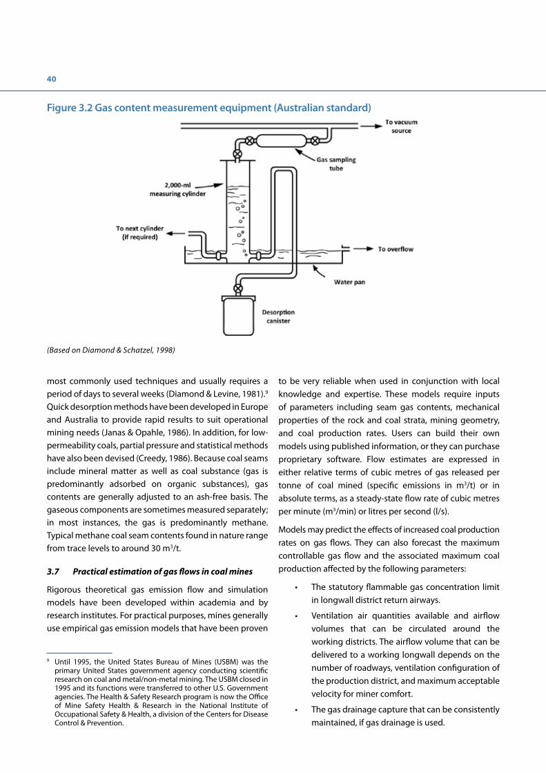
40
most commonly used techniques and usually requires a period of days to several weeks (Diamond & Levine, 1981).9 Quick desorption methods have been developed in Europe and Australia to provide rapid results to suit operational mining needs (Janas & Opahle, 1986). In addition, for low-permeability coals, partial pressure and statistical methods have also been devised (Creedy, 1986). Because coal seams include mineral matter as well as coal substance (gas is predominantly adsorbed on organic substances), gas contents are generally adjusted to an ash-free basis. The gaseous components are sometimes measured separately; in most instances, the gas is predominantly methane. Typical methane coal seam contents found in nature range from trace levels to around 30 m3/t.
3.7 Practical estimation of gas flows in coal mines
Rigorous theoretical gas emission flow and simulation models have been developed within academia and by research institutes. For practical purposes, mines generally use empirical gas emission models that have been proven
9 Until 1995, the United States Bureau of Mines (USBM) was the primary United States government agency conducting scientific research on coal and metal/non-metal mining. The USBM closed in 1995 and its functions were transferred to other U.S. Government agencies. The Health & Safety Research program is now the Office of Mine Safety Health & Research in the National Institute of Occupational Safety & Health, a division of the Centers for Disease Control & Prevention.
to be very reliable when used in conjunction with local knowledge and expertise. These models require inputs of parameters including seam gas contents, mechanical properties of the rock and coal strata, mining geometry, and coal production rates. Users can build their own models using published information, or they can purchase proprietary software. Flow estimates are expressed in either relative terms of cubic metres of gas released per tonne of coal mined (specific emissions in m3/t) or in absolute terms, as a steady-state flow rate of cubic metres per minute (m3/min) or litres per second (l/s).
Models may predict the effects of increased coal production rates on gas flows. They can also forecast the maximum controllable gas flow and the associated maximum coal production affected by the following parameters:
• The statutory flammable gas concentration limit in longwall district return airways.
• Ventilation air quantities available and airflow volumes that can be circulated around the working districts. The airflow volume that can be delivered to a working longwall depends on the number of roadways, ventilation configuration of the production district, and maximum acceptable velocity for miner comfort.
• The gas drainage capture that can be consistently maintained, if gas drainage is used.
Figure 3.2 Gas content measurement equipment (Australian standard)
(Based on Diamond & Schatzel, 1998)

41


Chapter 4. Mine ventilation
Key messagesMine ventilation systems are critical components of an overall mining operation to effectively remove methane from mine workings. A mine ventilation system is designed to achieve three objectives: 1) deliver breathable fresh air to the workers, 2) control mine air temperature and humidity, and 3) effectively dilute or remove hazardous gases and airborne respirable dust.
Improvements to methane drainage systems can often provide a more rapid and cost-effective solution to mine gas problems than simply increasing the mine’s air supply.
4.1 Ventilation challenges
Achieving effective ventilation in coal mines is ultimately the factor that limits coal production at a given mine. The maximum rate of coal extraction that can be safely achieved on a gassy working coalface is determined by the combination of ventilation capacity to dilute pollutants to acceptable concentrations and methane drainage efficiency.
Ventilation is the primary means of diluting and dispersing hazardous gases in underground mine roadways. Air velocities and quantities are optimised to ensure dilution of gas, dust, and to ensure control of heat. The greater the fresh air quantity supplied to the coalface, the greater the inflow of gas that can be diluted. This dilution process is inherently limited by air availability within the mine and maximum tolerable air velocities.
Ventilation pressure is proportional to the square of the airflow volume. A modest rise in air quantity therefore requires a significant increase in pressure, which leads to greater leakages across goafs and ventilation doors. Excessive leakage flows across the goafs may also increase spontaneous combustion risks and can impair gas drainage systems.
The volume of air required to ventilate the underground workings and the permissible level of pollutants is often mandated by local government agencies. A ventilation system that is designed simply to comply with legal minimum airflows or air velocities may be inadequate for the purpose of maintaining a safe and satisfactory environment in an active mine. For this reason, ventilation
system design specifications must take into account the expected worst-case pollutant levels.
Methane is considered the principal pollutant and the most hazardous gas for ventilation system specifications. If the selected ventilation system design is capable of removing or satisfactorily controlling the primary pollutant, it is assumed that the lesser pollutants will be adequately controlled or removed at the same time.
4.2 Key ventilation design features
Generally, air is drawn (sucked) through a mine by exhaust fans located on the surface. Thus, the air pressure in the mine is below atmospheric pressure. In the event of fan failure, the ventilation pressure in the mine rises, preventing an instantaneous release of gas from worked areas.
A deeper and more extensive mine can require a more complex ventilation circuit. However, added complexity may result in a greater propensity for leakage losses through communicating doors in the mine between intake and return airways. Thus complex and larger mines have limited quantities of fresh air available for use in blind headings and on working coalfaces, which requires the use of auxiliary ventilation ducts. Nevertheless, sufficient air must be supplied to allow headings to be ventilated in parallel and not in series; with the latter arrangement, a gas problem in one heading will be rapidly transmitted to the next. Best practice is to make arrangements for the supply of electricity to be cut off from all working places downstream of a working place in which the methane concentration has exceeded the statutory maximum.
Ventilation requirements are dynamic. Ventilation air demand increases as a mine is developed and the area being ventilated increases, sometimes requiring installation of additional ventilation shafts, upgrading fans, or enlarging existing airways.
Proprietary software is available for modelling ventilation networks. Actual pressure and flow surveys should be made at regular intervals to calibrate the model and check the system performance as changes are made.
Whenever possible, the ventilation system should be designed so that the various ventilation “splits” or

44
branches are naturally balanced. This action reduces the need to install flow-control devices such as air locks. The opening and closing of such devices to allow the passage of personnel has a profound effect on the airflows in the branch (entries).
The surface fan(s) should be designed to satisfy the mine ventilation requirements. Surface fans can generally be adjusted within certain limits to ensure that they meet the requirements without suffering aerodynamic instability. Older surface fans installed at some mature mines are often operating at their design maximum duty. In such cases, any increase in airflows to the more remote parts of the mine can only be achieved by improvements to the ventilation air network.
4.3 Ventilation of gassy working faces
Different ventilation configurations control the gas, dust, and heat that result from coal extraction with varying degrees of effectiveness. The principal gas risks are associated with areas of coal workings in which the seam has been partially or wholly extracted (whether by longwall or room-and-pillar methods) and are no longer safely accessible (i.e., goafs). All longwall or pillar recovery operations are in direct contact with mined-out areas where methane, oxygen-deficient air, and other hazardous gases can accumulate. These gases include methane not captured by gas drainage, plus continuing emissions from coal left in the goaf.
These gases are handled in one of two ways at the ventilation control level. First, they may be allowed to enter the mine air stream where sufficient air is available to dilute the maximum expected gas flows in the airways to safe concentrations (Figure 4.1). As an example, a longwall with U-ventilation, as shown in Figure 4.2, and 50% methane capture can handle a total gas flow of 800 l/s (48 m3/min) pure methane.10 A best practice multi-entry longwall and 70% methane capture can control 5,333 l/s (320 m3/min) pure methane, an increase by a factor of more than six.11,12
Secondly, where permitted by local spontaneous combustion propensity or local strata behaviour, some portion of the gas may be diverted into a bleeder road behind the face, or across old goafs, to discharge into main returns or at bleeder shafts (i.e., a vertical shaft through which gas-laden air from working districts is discharged, commonly used in the U.S). The efficiency of these “bleeder” systems depends on the distribution of ventilation pressures in the workings, which are adjusted using partial obstructions (regulators) in the airways. The methane concentrations in bleeder roads in some countries are regulated to below 2% to reduce explosion risk.
10 Single intake airway and a single return airway, 2% maximum methane and 30 m3/s air.
11 Multiple entry, 2% maximum methane and 120 m3/s air.12 In both cases, an allowance is made for peaks 50% above the
mean.
Figure 4.1 Airflows required for diluting longwall methane emissions to 2%, allowing for peaks
(Courtesy of Sindicatum Sustainable Resources)
0
10
20
30
40
50
60
70
0 20 40 60 80 100
Total air�ow m3/s
Drainage capture e�ciency %
250 l/s
500 l/s
750 l/s
1000 l/s

45
There is a practical upper limit to the quantity of air that can be passed along a coalface without creating an unacceptable working environment, mainly due to airborne dust particles. Coalface airflow limitations restrict the ventilation achievable in the conventional U-ventilation system (Figure 4.2). Where the available airflow is insufficient to dilute the gas emitted from the workings, additional air can be introduced independently by adopting mine layouts in various configurations such as the “3-Road” and “Y” systems, shown in Figure 4.3. These ventilation systems, however, require higher investment such as driving of an additional roadway, roadside dam (pack wall), and strong support of the roadways remaining open behind the longwall in the goaf. In Figures 4.2 and 4.3, broad blue arrows show direction of mining, light blue arrows show direction of air flowing from intake, and red arrows show direction of return air flow.
Regardless of whichever system or layout is being used, a sufficient volume of fresh air must arrive at the coal-cutting machine to dilute the coal front gas (arising from the
remaining seam gas content after any predrainage) and to the return end (tailgate corner) of the longwall face to satisfy the local statutory limit. The selected layout should be capable of providing a good standard of ventilation at the most effective methane drainage drilling locations. If this standard is not achieved, it will result in lower drainage efficiency, greater ventilation air demand, and reduced coal production.
Gas control and access for drilling and regulating cross-measure drainage boreholes is simpler on advancing compared with retreating longwalls. However, most of the world’s longwall coal production comes from retreating coalfaces as these are more productive, and ventilation configurations have been developed as attempts to incorporate the advantages of both by ventilating behind the coalface such as “Y,” “H,” and back-return systems.13 The ventilation system should incorporate some means of creating a pressure gradient at longwall face-ends to
13 See Figure 9.1 in Case Study 1 for an example of a back-return system.
Figure 4.2 Conventional U-type ventilation system
Figure 4.3 Ventilation layouts used on gassy longwall working faces
Goaf
Unmined Coal
H-type ventilation system
Goaf
Unmined Coal
3-road ventilation system Advanced Y-type ventilation system
Unmined Coal Unmined Coal
Goaf Goaf
High performance longwall operations in areas with high gas emissions-Germany
Situation: A maximum permissible airflow of 25 m3/s across the longwall coalface could only dilute a maximum gas inflow of 0.37 m3/s (22.2 m3/min), despite a relaxation by the mining authority which raised the maximum permitted methane concentration from 1.0% to 1.5% (a reduction in factor of safety from 5.0 to 3.3). Predrainage was evaluated and determined to be ineffective.
Solution: A Y-ventilation system was designed to introduce a further 50 m3/s of air and add to the 25 m3/s passing across the face, the combined flow passing behind the face diluting the methane emitted from the coalface and the goaf. The ventilation configu-ration allows cross-measure boreholes to be drilled, connected to the drainage system and individually monitored and regulated.
Please see case study 2 for more information.

46
ensure that flammable gas mixtures do not circulate to the working face. This can involve use of regulators (partial obstructions) in roadways and special face-end ventilation arrangements to divert airflow along the waste edge behind the coalface.
4.4 Ventilation system power requirement
A small change in air volume transported by the mine ventilation system requires a much larger change in power consumption and hence ventilation cost. The ventilation system power requirement, which is one of the most important operating costs at a mine, is proportional to the air volume flow cubed (Figure 4.4). Therefore, introducing gas drainage or increasing its effectiveness often represents a lower-cost option than increasing ventilation air volumes, which might also involve major infrastructure development in the mine.
4.5 Ventilation of coal headings
Effective gas control in blind headings and room-and-pillar mines can be achieved by a combination of providing auxiliary ventilation and using cutting machine-mounted ventilation devices to dilute gas released when cutting coal.
Coal headings are usually ventilated by an auxiliary fan and duct system, either exhausting or forcing, or a combination of the two. Gas hazards can develop rapidly in the event of any failure of the auxiliary ventilation system. Once gas has
accumulated, safe re-entry to a heading requires special procedures to ensure that gas has been removed in a safe manner. To reduce gas accumulation risks, some mines allow automatic restart of underground fans following short stoppages under certain conditions. Where methane has accumulated in a heading after a ventilation failure, a carefully organised degassing procedure must be implemented to prevent the uncontrolled release of a high concentration plug of methane into the main ventilation system.
Figure 4.4 Example of ventilation air power requirement versus airflow
(Courtesy of Sindicatum Sustainable Resources
0
100
200
300
400
500
600
0 20 40 60 80 100 120
Power kW
Air�ow m3/s
Lorem ipsum
Reducing explosion risk in room-and-pillar mines-South Africa
Situation: The mined sections cannot be effectively ventilat-ed due to the massive amounts of air required and the diffi-culty of distributing it evenly. To ensure main ventilation flows reach the working faces, these worked-out areas are closed off with temporary screens; gas therefore accumulates in the en-closed areas behind the face.
Solution: Measures were recommended including: 1) Use of effective auxiliary ventilation in headings (secondary ventila-tion); 2) Regular measurement and recording of critical ven-tilation data; 3) Inspections of gassy sections at intervals not exceeding one hour; and 4) continuous gas monitoring in the heading being mined.
Please see case study 9 for more information.

47
Ventilation system failures due to power interruptions, mechanical faults, and faulty auxiliary fan ducting have been a contributory factor in many serious gas-related accidents. Dual power supplies to mines and standby surface and underground booster fans ensure redundancy in the main ventilation system.
4.6 Ventilation air flow monitoring
Ventilation monitoring can be performed in two primary ways: 1) continuously using fixed air velocity transducers transmitting data to the surface, or 2) periodically using calibrated, hand-held equipment.
The accuracy of continuous flow monitoring depends on several factors: the positioning of transducers, proper calibration, and the cross-sectional area of the roadway, which can change over time as a result of mining disturbance. Airflows in working districts and headings should be monitored continuously, as they are critical to both safety and coal production.
Measuring locations should not be sited where obstructions are present, such as locomotives or other parked vehicles, as these disturbances will create intermittent changes in local air velocity.
Hand-held vane anemometers are suitable for use anywhere in a mine, including dynamically active areas, because the airway dimensions can be checked with every air velocity measurement. Air measuring devices
must be recalibrated at fixed time intervals to ensure their accuracy.
4.7 Ventilation control
Distribution control includes redirecting airflow to one location at the expense of other airflows. The relationship between aerodynamic resistance, air pressure, and rate of airflow is well known, and can be used to predict the outcome of airflow redistributions.
Overall control of the mine ventilation system is directed primarily by the surface fan(s). Increasing the differential surface fan pressure applied at a mine may have only negligible effect on airflows in the most remote parts of the mine. For this reason, increasing surface fan pressure may not solve a problem of shortfall in ventilating airflows in remote working areas. Strata pressures may cause the roof, ribs, and floor toam not sure this answers what you were asking. ke where roadsjoin. on title?entialtion converge, which causes increased resistance to airflow; therefore, roadways must be maintained to facilitate efficient ventilation as designed.
Continuously controlling and adjusting the main fan is not advisable. Where a mine is served by a redundantly designed surface fan system (one or more fans running, and one or more fans on standby), using a fan changeover facility is preferable to ensure that mine airflows are not interrupted when the surface fans are stopped for routine maintenance or inspection.

Chapter 5. Methane drainage
Key messagesExperience in industrialised countries shows that investment in good gas drainage practices results in less mine downtime due to gassy mine conditions, safer mining environments, and the opportunity to utilise more gas and reduce mine methane emissions.
Practical gas drainage problems at coal mines can generally be resolved by applying existing knowledge and techniques. Introducing new or novel technologies should only be considered after application of good practices, and only if currently employed techniques have failed to provide a satisfactory solution. Rigorous testing should precede introduction of any technology into the mining environment to ensure that safety is not compromised and best practices are maintained.
Methane drainage system performance can be improved through proper installation, maintenance, regular monitoring, and implementation of systematic drilling plans.
Transporting methane-air mixtures at concentrations in or near the explosive range in coal mines is a dangerous practice and should be prohibited.
5.1 Methane drainage and its challenges
The purpose of methane drainage is to capture high-purity gas at its source before it can enter mine airways. For regulatory purposes, the amount of gas released into the air flow must not exceed the capacity of the ventilation air used to dilute gaseous pollutants to mandated safety levels; however, there is a strong motivation for maximising gas capture to achieve enhanced safety, environmental mitigation, and energy recovery.
There is a wide range of gas capture methods. Choosing unsuitable methods or poor implementation of those methods will result in low drainage efficiencies and excessive ingress of air, producing flows of low-concentration methane in captured gas. When these gases are in or near the explosive range during transport and use, they create hazards.
5.2 Basic principles of methane drainage practices employed worldwide
Differing geological and mining conditions in the world’s coal basins have resulted in the development of different methane drainage techniques.
Methane drainage methods are conventionally classified as involving either predrainage or postdrainage techniques. Predrainage involves removing methane from the seam to be worked in advance of mining, while postdrainage involves capturing methane and other gases released from surrounding seams as a consequence of the strata movement, relaxation, and increased permeability induced by mining. A summary of the most common methane drainage methods is provided in Appendix 1. Predrainage methods described in this chapter generally refer to situations found in underground mines; issues unique to predrainage of methane from surface mines are addressed in Chapter 6.
Good practice postdrainage techniques can typically capture 50% to 80% of the total gas from a longwall district in the absence of unusual geological conditions. 50% gas capture from the entire mine is an achievable target in most cases. Methane concentrations of 30% and higher should be achievable using postdrainage systems in all but the most challenging mining conditions. Concentrations of 60% and higher should be achievable from predrainage methods.
5.3 Predrainage basics
Predrainage can be achieved by both in-seam boreholes and by boreholes drilled from surface. Predrainage is the only means of reducing gas flow directly from the worked seam, which can be important if the seam being extracted is the main gas emission source. Predrainage is also sometimes necessary for reducing outburst risks (see Case Study 3). Because the drainage is undertaken before mining, the collection systems are not likely to be disturbed by ground movement, and, if feasible, relatively high purities of gas can usually be extracted. Drainage from blocks of coal ahead of mining generally produces consistent gas flows of high purity but predrainage is generally only effective when the permeability and gas contents of the coal are sufficient to allow significant gas flow. Significant gas flows into virgin headings are indicative of medium- to high-fracture permeability and present potential for both effective predrainage and gas utilisation.
Coal permeability directly affects the time required to sufficiently drain the coal seam. The lower the coal’s

50
permeability, the more time is needed to drain gas to reduce coal seam gas content to a required average value. Alternately, the lower permeability coals require a greater number of boreholes needed to achieve the desired methane levels in advance of mining. The available time for degassing and the cost of the drilling operation determines the ultimate feasibility of premine degasification under site-specific conditions.
Various mine predrainage techniques are in use globally. Rotary drilling is commonly employed for drilling underground in-seam holes of 100 m to 200 m. However, holes of 1,000 m or more can be installed using underground directional drilling techniques, thereby increasing the efficiency of degassing. Furthermore, where mines are not too deep, extensive in-seam drilling and degassing can be carried out from the surface. Surface to in-seam directional drilling techniques have proved effective in pre-draining coal seams with a permeability range of approximately 0.5 millidarcy (mD) to 10 mD (i.e., approximately 5*10-4 (µm)2 to 10-2 (µm)2) and even less. A combination of pre- and postdrainage using advanced, surface-based in-seam and underground in-seam directional drilling techniques are utilised in Australia, where total mine emissions can reach
9,500 l/s and longwall capture efficiencies of 80% to 85% are required for high production retreat longwalls (Belle, 2016). Due to the poor performance of surface to in-seam systems and associated operating costs, underground in-seam drainage has been favoured in Australia (Belle, 2016). Australian and U.S. experience (Von Schonfeldt, 2008) has shown that where surface to in-seam drilling is possible, the technique is superior to underground in-seam drilling because the borehole can be drilled well in advance of mining and therefore less likely for effective drainage to be shortened by coal production activities (Black & Aziz, 2009). Figure 5.1 shows a potential drilling configuration that can be used to drain gas from coal before mining commences. In this schematic, two minable seams will be drained by first drilling a pilot well from which two lateral well bores are drilled into each of the seams. After the lateral wells are placed, another vertical well is drilled to intersect the laterals. Water and gas is produced from the vertical well and the pilot well is shut-in or abandoned. Figure 5.2 depicts post-mining drainage alternatives, but cross-measure boreholes and directionally or guided boreholes (in advance of mining) can be drilled in much the same configuration.
Figure 5.1 Schematic of premine drainage from lateral wells drilled from the surface
(Courtesy of Raven Ridge Resources, Incorporated)
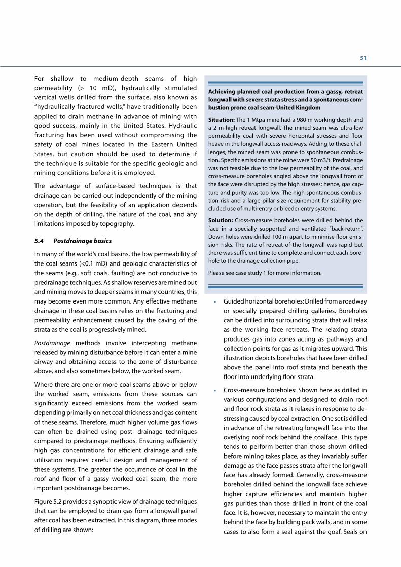
51
For shallow to medium-depth seams of high permeability (> 10 mD), hydraulically stimulated vertical wells drilled from the surface, also known as “hydraulically fractured wells,” have traditionally been applied to drain methane in advance of mining with good success, mainly in the United States. Hydraulic fracturing has been used without compromising the safety of coal mines located in the Eastern United States, but caution should be used to determine if the technique is suitable for the specific geologic and mining conditions before it is employed.
The advantage of surface-based techniques is that drainage can be carried out independently of the mining operation, but the feasibility of an application depends on the depth of drilling, the nature of the coal, and any limitations imposed by topography.
5.4 Postdrainage basics
In many of the world’s coal basins, the low permeability of the coal seams (<0.1 mD) and geologic characteristics of the seams (e.g., soft coals, faulting) are not conducive to predrainage techniques. As shallow reserves are mined out and mining moves to deeper seams in many countries, this may become even more common. Any effective methane drainage in these coal basins relies on the fracturing and permeability enhancement caused by the caving of the strata as the coal is progressively mined.
Postdrainage methods involve intercepting methane released by mining disturbance before it can enter a mine airway and obtaining access to the zone of disturbance above, and also sometimes below, the worked seam.
Where there are one or more coal seams above or below the worked seam, emissions from these sources can significantly exceed emissions from the worked seam depending primarily on net coal thickness and gas content of these seams. Therefore, much higher volume gas flows can often be drained using post- drainage techniques compared to predrainage methods. Ensuring sufficiently high gas concentrations for efficient drainage and safe utilisation requires careful design and management of these systems. The greater the occurrence of coal in the roof and floor of a gassy worked coal seam, the more important postdrainage becomes.
Figure 5.2 provides a synoptic view of drainage techniques that can be employed to drain gas from a longwall panel after coal has been extracted. In this diagram, three modes of drilling are shown:
• Guided horizontal boreholes: Drilled from a roadway or specially prepared drilling galleries. Boreholes can be drilled into surrounding strata that will relax as the working face retreats. The relaxing strata produces gas into zones acting as pathways and collection points for gas as it migrates upward. This illustration depicts boreholes that have been drilled above the panel into roof strata and beneath the floor into underlying floor strata.
• Cross-measure boreholes: Shown here as drilled in various configurations and designed to drain roof and floor rock strata as it relaxes in response to de-stressing caused by coal extraction. One set is drilled in advance of the retreating longwall face into the overlying roof rock behind the coalface. This type tends to perform better than those shown drilled before mining takes place, as they invariably suffer damage as the face passes strata after the longwall face has already formed. Generally, cross-measure boreholes drilled behind the longwall face achieve higher capture efficiencies and maintain higher gas purities than those drilled in front of the coal face. It is, however, necessary to maintain the entry behind the face by building pack walls, and in some cases to also form a seal against the goaf. Seals on
Achieving planned coal production from a gassy, retreat longwall with severe strata stress and a spontaneous com-bustion prone coal seam-United Kingdom
Situation: The 1 Mtpa mine had a 980 m working depth and a 2 m-high retreat longwall. The mined seam was ultra-low permeability coal with severe horizontal stresses and floor heave in the longwall access roadways. Adding to these chal-lenges, the mined seam was prone to spontaneous combus-tion. Specific emissions at the mine were 50 m3/t. Predrainage was not feasible due to the low permeability of the coal, and cross-measure boreholes angled above the longwall front of the face were disrupted by the high stresses; hence, gas cap-ture and purity was too low. The high spontaneous combus-tion risk and a large pillar size requirement for stability pre-cluded use of multi-entry or bleeder entry systems.
Solution: Cross-measure boreholes were drilled behind the face in a specially supported and ventilated “back-return”. Down-holes were drilled 100 m apart to minimise floor emis-sion risks. The rate of retreat of the longwall was rapid but there was sufficient time to complete and connect each bore-hole to the drainage collection pipe.
Please see case study 1 for more information.
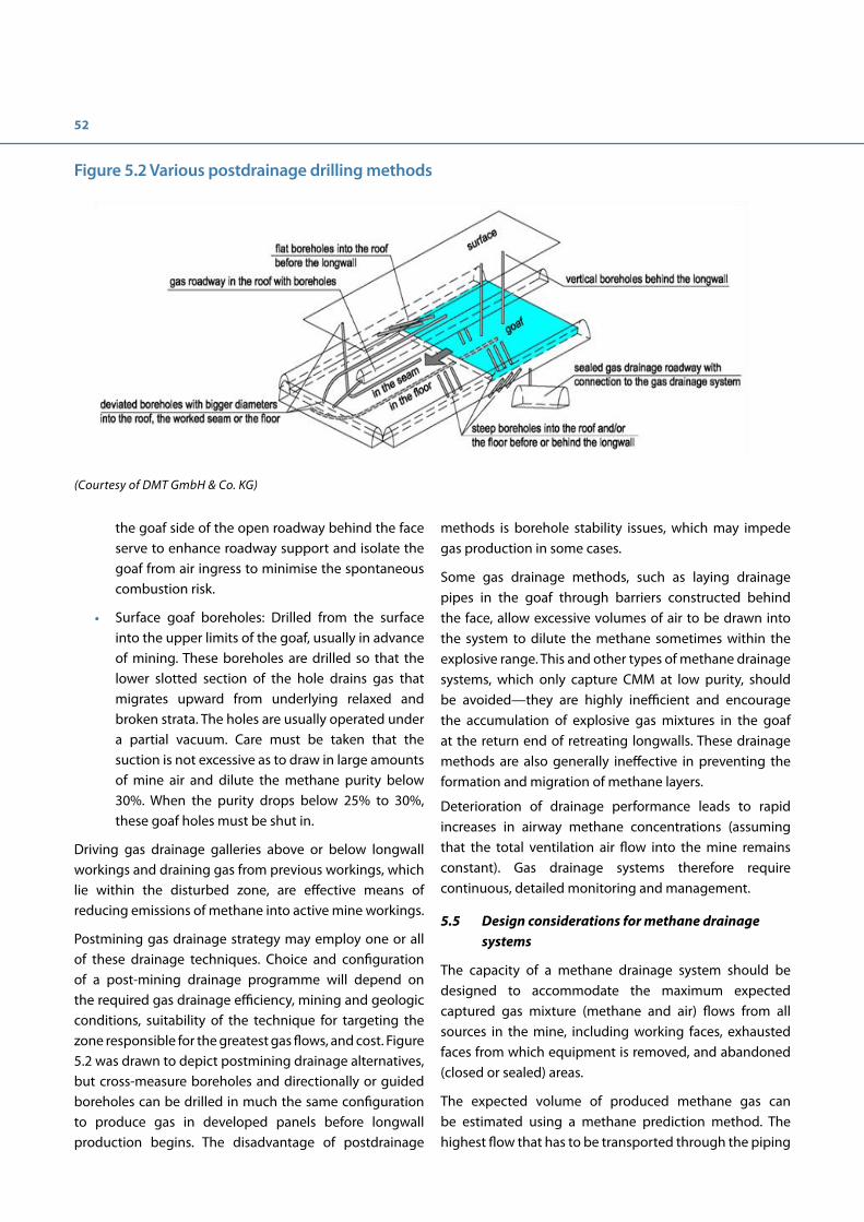
52
the goaf side of the open roadway behind the face serve to enhance roadway support and isolate the goaf from air ingress to minimise the spontaneous combustion risk.
• Surface goaf boreholes: Drilled from the surface into the upper limits of the goaf, usually in advance of mining. These boreholes are drilled so that the lower slotted section of the hole drains gas that migrates upward from underlying relaxed and broken strata. The holes are usually operated under a partial vacuum. Care must be taken that the suction is not excessive as to draw in large amounts of mine air and dilute the methane purity below 30%. When the purity drops below 25% to 30%, these goaf holes must be shut in.
Driving gas drainage galleries above or below longwall workings and draining gas from previous workings, which lie within the disturbed zone, are effective means of reducing emissions of methane into active mine workings.
Postmining gas drainage strategy may employ one or all of these drainage techniques. Choice and configuration of a post-mining drainage programme will depend on the required gas drainage efficiency, mining and geologic conditions, suitability of the technique for targeting the zone responsible for the greatest gas flows, and cost. Figure 5.2 was drawn to depict postmining drainage alternatives, but cross-measure boreholes and directionally or guided boreholes can be drilled in much the same configuration to produce gas in developed panels before longwall production begins. The disadvantage of postdrainage
methods is borehole stability issues, which may impede gas production in some cases.
Some gas drainage methods, such as laying drainage pipes in the goaf through barriers constructed behind the face, allow excessive volumes of air to be drawn into the system to dilute the methane sometimes within the explosive range. This and other types of methane drainage systems, which only capture CMM at low purity, should be avoided—they are highly inefficient and encourage the accumulation of explosive gas mixtures in the goaf at the return end of retreating longwalls. These drainage methods are also generally ineffective in preventing the formation and migration of methane layers.
Deterioration of drainage performance leads to rapid increases in airway methane concentrations (assuming that the total ventilation air flow into the mine remains constant). Gas drainage systems therefore require continuous, detailed monitoring and management.
5.5 Design considerations for methane drainage systems
The capacity of a methane drainage system should be designed to accommodate the maximum expected captured gas mixture (methane and air) flows from all sources in the mine, including working faces, exhausted faces from which equipment is removed, and abandoned (closed or sealed) areas.
The expected volume of produced methane gas can be estimated using a methane prediction method. The highest flow that has to be transported through the piping
Figure 5.2 Various postdrainage drilling methods
(Courtesy of DMT GmbH & Co. KG)

53
network is given by the highest expected captured gas flow with the lowest methane concentrations (purity) likely to arise during normal operations. The resulting flow rate should be within the system’s planned capacity when all the pumps are operating.
Gas quality is a design feature of the gas drainage system, not an inherent or natural characteristic. Gas purity of less than 30% methane in air should be considered unacceptable for both safety and efficiency reasons. The maintenance of gas purity in underground drainage systems depends on the quality of borehole sealing, including proper installation of standpipes, the systematic regulation of individual boreholes, and the suction pressure applied at the surface extraction plant. Increasing suction in an effort to increase gas flow will introduce more air and hence reduce the gas purity. Conversely, reducing suction will reduce the total mixture flow but improve gas purity. Most importantly, suction and flow at the surface plant should only be adjusted with a full knowledge of the underground status and while maintaining communication with the longwall ventilation supervisors.
When planning, implementing, and managing a methane drainage system, the following factors should be taken into account:
• Safety of access for drilling, monitoring, and regulation.
• Ground stability and necessary support systems to stabilise boreholes.
• Gas drainage borehole configurations, with consideration given to differences between the expected performance of roof and floor post drainage boreholes.
• Drainage capacity, pipe diameters, extraction pump, and infrastructure requirements.
• Location, installation, and commissioning of the drainage pipe network.
• Water traps and dewatering facilities.
• Operational control and maintenance of the drainage system and infrastructure.
• Monitoring of boreholes, pipe networks, and the surface extraction plant.
• Protection of gas drainage pipes from crushing behind longwall retreat faces.
5.6 Underground gas pipeline infrastructure
Suitable materials should be used for gas drainage pipe-work infrastructure. Steel, glass-reinforced plastic (GRP), and polyethylene (PE) gas drainage pipe is available.
GRP pipelines are relatively brittle and should not be used in coal-production districts; however, their ease of handling and installation, compared with steel pipe, makes them the preferred material for the main trunk lines.
Where space is restricted and the line might be vulnerable to physical damage (e.g., from roadway deformation or free-steered vehicles), steel pipe should be used and connected using proprietary flexible joints to allow movement.
PE pipe is used in some countries, but high-temperature fusion of these pipe joints or segments underground should be avoided. Safety regulators in some countries allow this practice in well-ventilated areas under supervision of qualified mine safety personnel, whereas in other countries, it is deemed unacceptable. In addition, a conductive medium is necessary to reduce risk of static discharge.
Regardless of material choice and positioning, underground pipe systems are vulnerable to damage even in the most regulated mines. The principal potential source of damage is mining equipment, including mineral conveyors, rope haulage systems, locomotives and their loads, and blasting activities. There is also the potential for damage from strata movement and roof collapse. The drainage system should
High performance longwall operations in areas with high gas emissions-Australia
Situation: At an Australian mine, a new series of longwall blocks is located in a 2.8 m-high seam with methane contents ranging from 8 to 17 m3/t. Depth of cover is 250 m to 500 m. Gas emission predictions indicate likely specific emissions of 15 to 30 m3/t from coal seam sources. Gas flows could reach 9.5 m3/s.
Solution: To date, the mine has successfully employed con-ventional surface to goaf drainage holes (300 millimetre di-ameter at 50 m spacing located on the tailgate return side) to reduce the gas emission load on the ventilation system. This strategy has achieved an average 75% capture (goaf drainage plus ventilation) with peaks of about 85% capture and a high gas stream purity (>90% CH4).
Please see case study 3 for more information.

54
therefore be designed and operated with the premise that there is a finite risk of integrity failure.
5.7 Monitoring of gas drainage systems
Manual or remote monitoring systems should be used to determine the effectiveness of the gas drainage system. Monitoring quality depends on the sensors’ reliability, positioning, maintenance, calibration, and use.
Measurements are needed at individual boreholes, in gas drainage pipe-work, and at the surface methane extraction plant that houses the pumps that draw the drained gas out of the mine. Parameters to be monitored include mixture flow, gas concentration, gauge pressure, and temperature. Barometric pressure should also be recorded to facilitate
standardisation of flow data. In some instances, gas being drained or emitted into the mine workings may contain heavier gaseous hydrocarbons, such as ethane or propane. These hydrocarbon species can distort the response from conventional infrared-based gas detection systems, and cause inaccurate measurement of methane. Care should be taken to select monitoring equipment that is capable of correcting for non-methane hydrocarbons so that accurate measurements are ensured.
Monitoring should be used to assess the actual performance of the installed system against the original design concept. In some countries, such as the United States, authorities require monitoring, reporting and verification of greenhouse gas emissions from coal mines.14
14 In response to the 2008 Consolidated Appropriations Act passed by the U.S. Congress, the U.S. Environmental Protection Agency (USEPA) issued the Mandatory Reporting of Greenhouse Gases Rule. The regulation requires reporting of greenhouse gas (GHG) data and other relevant information from large sources and suppliers in the United States including underground coal mines that liberate at least 701 metric tonnes per year of methane (36.5 million cubic feet or 1.03 million cubic metres per year). In 2014, 128 mines reported emissions to the GHGRP. Data reported by coal mines to the Greenhouse Gas Reporting Program is public and is available on the USEPA website. The rule is for reporting only and does not mandate emission controls, nor does it include an emissions trading programme.

55


Chapter 6. Methane utilisation and abatement
Key messagesUnderground coal mines are one of the largest sources of anthropogenic methane emissions, but these emissions can be substantially reduced through implementation of best practices. Methane has a GWP 28-34 times higher than carbon dioxide, the most important GHG globally.
Much of the methane produced from underground mines can be used or destroyed by the mining industry. Options include exploitation of the drained gas, flaring excess drained gas, and use or abatement of mine VAM. With the right technical and market conditions, the ultimate goal should be near zero methane emissions.
In the rush to exploit CMM, necessary safety and engineering standards have sometimes been neglected, creating new hazards at coal mines. Any increase in underground risk should be avoided in planning methane utilisation.
6.1 Coal mine methane and climate change mitigation
Reduction of methane emissions is an international priority in which coal mines can play an important role. Methane accounts for 20% of global anthropogenic GHG emissions, and coal mines constitute 8% of methane emissions or
about 400 MtCO2e annually (USEPA, 2012; IPCC, 2014). Global CMM emissions may be relatively small compared to the other coal-related GHG emission source of carbon dioxide emissions from coal combustion, but they are significant. On a facility-basis, CMM emissions can be very large totalling more than 1 million tonnes CO2 per annum. More importantly, the technologies to recover and utilise CMM are commercially available and proven, making CMM use an attractive near- and medium-term GHG abatement solution for the coal industry.
6.2 Mine methane as an energy resource
Methane capture and use can add significant value to the mining operation. Captured CMM can be directly used to supply or generate energy, harnessing the value of a natural resource. In turn, this can deliver economic returns for the mine through energy sales or cost savings. Moreover, methane utilisation adds intrinsic value by generating capital that can be reinvested in mine safety equipment and operations. CMM capture and use can be a core component of a Corporate Social Responsibility strategy, a very important advantage at a time of growing global concern over the impacts of climate change and the sustainability of extractive industries.
Figure 6.1 Optimising energy recovery with near-zero methane emissions mining
(Courtesy of Sindicatum Sustainable Resources)

58
6.2.1 Underground mine methane
Existing technology is able to optimise energy recovery and virtually eliminate a substantial percentage of methane emissions from underground coal mining (Figure 6.1). Good gas drainage standards and practices will yield gas of stable and usable quality, and will facilitate application of the lowest cost utilisation opportunities. Due to mining variations, gas supply will fluctuate and utilisation equipment will occasionally fail or need to be stopped for maintenance. The unused gas can then be flared to minimise emissions. Methane that cannot be captured and used is diluted in ventilation air and emitted to the atmosphere as VAM. Technologies to reduce VAM emissions have been in development for many years. Generally, it is technically feasible to oxidise VAM at concentrations above 0.20%, and there are several commercial projects now in operation around the world.
Safety must always remain the highest priority in managing methane at underground coal mines. In the rush to exploit CMM, necessary safety and engineering standards are sometimes neglected, creating new hazards at coal mines. In planning methane utilisation, any increase in underground risk should be avoided.
6.2.2 Surface mine methane
Methane can be captured from surface mines using technology that has been developed and employed for coalbed methane production; however, effective drainage and capture of methane that would otherwise be released during coal extraction requires that drainage holes are
drilled in advance of mining. In order to be cost-effective, the drilling programme must be coordinated with the mine’s extraction and timing plans. Coordination with the mine operations ensures that the gas producer will have ample opportunity after the well is drilled to profitably recover the gas resource and make the investment worthwhile.
Surface coal mines are designed as either open pit mines or strip mines, each of which offers opportunities and challenges for methane drainage. Strip mines are laid out along the strike of the target coal seam, swathes of which are extracted as strips of overburden are removed. As the mine advances, earth that is removed from subsequent strips is deposited in the mined-out areas. Vertical boreholes can be used to drain the coal seam prior to the start of excavation, but they must be placed so that they remain undisturbed by mining activities and drilled sufficiently prior to the advance of mining to allow for effective drainage. Boreholes drilled directionally from the surface can also be used to effectively drain the coal seam (Figure 6-2). These boreholes can be especially effective if positioned such that the wellbore underlies the disturbed area and remains within the coal seam being mined. As overburden is removed, relaxation of the underlying strata takes place, which to some extent, increases permeability and drainage efficiency.
Open pit mines are designed such that overburden is excavated in a series of concentric levels or benches that step down from the surface to the bottom of the pit. Pit walls are designed for slope stability and preventing rock falls or wall failure. Haulage roads are located along the benches so that coal and/or waste rock can be hauled to
Figure 6.2 Cross-section through a strip mine showing possible placement of a directionally drilled borehole

59
the surface and deposited along the rims of the pit. As with strip mines, borehole placement and timing have to be coordinated with the open pit mine plan. Figure 6.3 illustrates how placement of boreholes could be coordinated with planned growth of the pit.
Vertical wells drilled from the surface have been used effectively in the United States’ Powder River Basin to drain gas from coal seams prior to mining. The key to success in this project was close coordination between the open pit coal mine operator and the owner of the rights to associated coalbed methane. The mineral rights were held by the U.S. Government, and the U.S. Bureau of Land Management reduced the royalty payments and lease rentals to provide an incentive for the gas producer, recognising that an incentive must be provided in order to ensure that the valuable gas resource was not wasted as the coal mine was developed. This example of coordinated coproduction of gas resulted in gas being produced and sold to pipeline rather than being lost to the atmosphere as mining proceeded (USEPA, 2014).
6.3 Use options
Potential utilisation of CMM in the range of 30% to 100% methane exists in a large variety of applications including: 1) use as fuel in steel furnaces, kilns, boilers, and industrial burners; 2) in internal combustion (IC) engines or turbines for power generation; 3) for injection to natural gas pipelines; 4) as feedstock in the fertiliser industry; or 5) as vehicle fuel (LNG or CNG). For offsite uses of gas, especially for civil customers, storage tanks are sometimes constructed to ensure peak demands can be met and to buffer supply in
the event of an interruption to gas extraction. The high cost, land use, visual impact, and risks associated with storing large volumes of flammable gas mixture are generally avoided at mine-based CMM power plants, many of which operate successfully on a live mine connection.
The Global Methane Initiative (www.globalmethane.org) has identified more than 200 operational CMM/VAM projects at active and abandoned mines worldwide. Figure 6.4 summarises the distribution of CMM/VAM project types, with power generation making up nearly 50 percent of the global projects. Taken together, the power generation projects provide approximately 709 megawatt (MW) of electricity generating capacity and the non-electricity generating projects deliver 2,716 million m3 per year of gas sales. The annual emission reductions in 2013 were equivalent to 29.4 million mtCO₂e (Global Methane Initiative, 2015).
To date, the majority of projects making use of captured methane have occurred in Australia, China, Czech Republic, Germany, Poland, the Russian Federation, Ukraine, the United Kingdom, and the United States with projects also in Mexico, Kazakhstan, Turkey, Romania, and South Africa. With the advent of carbon markets, there is growing value in some countries to the reduction of carbon emissions and resulting creation of carbon credits or other environmental commodities in addition to the energy commodities generated by such projects (see Chapter 7). This has spurred increased project activity in many countries, notably China, while also underpinning growth in project types solely dependent on carbon credits as the principal revenue source (e.g., flaring and VAM abatement).
Figure 6.3 Cut –away drawing showing vertically drilled boreholes relative to planned expansion of an open pit coal mine

60
6.4 Abatement and utilisation of drained methane
Utilisation of drained methane is dependent on the quantity and quality of the gas produced. Historically, methane concentrations of at least 30% were required. In recent years, combustion engines have begun appearing in the marketplace that are capable of using mine gas with methane concentrations less than 30%. This guidance differentiates the use of medium/high-concentration and low-concentration (< 30%) drained methane, because transportation of low-concentration gas is extremely dangerous and should be avoided.
6.4.1 Medium- to high-methane concentration CMM
Technologies in this category generally require a fairly consistent flow and quality of methane from drainage systems with a minimum methane concentration of 30% for transport safety reasons. Some applications are only commercially feasible with high-quality, pre-mining drained gas. There is no “one best use.” Each project should be evaluated on its own merits based on the quality and quantity of gas produced and the market, mining, operating, and legal conditions at each mine. For example, feed-in tariffs have been a major driver for CMM use in Germany, encouraging CMM-based power production. Many U.S. mines have access to a well-developed, natural gas transportation system with favourable natural gas pricing leading to a number of natural gas pipeline sales projects. Table 6.1 compares the most common end uses
Figure 6.4 Distribution of CMM project types worldwide
(Source: Global Methane Initiative Coal Mine Methane Projects Database, August 2015).
37
16
30
102
11 13
3
0
20
40
60
80
100
120
Direct Thermal Flaring PipelineInjection
Power/CHP Town Gas VAM Vehicle Fuel,LNG, CNG
Num
ber o
f Pro
ject
s
Development of a CMM power co-generation/emission abatement scheme-China
Situation: Gas purity at the extraction plant was variable and sometimes less than the 30% minimum permitted for utilisation and gas capture efficiency. Drained gas quantities were expected to fluctuate due to variations in the longwall mining cycle and the phasing of workings in different seams; therefore, the CMM power plant capacity needed to be sized to ensure 85% availability to meet investment requirements. An aim of the project was to optimise energy recovery and minimise GHG emissions.
Solution: Methane purity was raised by improving the sealing and regulation of cross-measure boreholes. The gas capacity of the drainage infrastructure was increased, high-resistance flow monitoring devices were replaced, and a plan prepared for increasing gas capture. Intensive predrainage drilling on two future longwall panels provided enrichment gas and also supplemented flow eventually contributing 23% of the drained gas, the remainder coming from postdrainage, roof cross-measure boreholes.
Please see case study 5 for more information.
of drained gas, briefly highlighting their advantages and disadvantages. For more information, users are encouraged to visit leading sources of information, including the Coalbed Methane Outreach Program (CMOP) website https://www3.epa.gov/cmop/ and the Global Methane Initiative web site (www.globalmethane.org).

61
Table 6.1 Comparison of CMM uses
Use Applications Advantages Disadvantages
Power generation
Gas-engine generators producing power for mine use or export to the grid
• Proven technology• Waste heat recovery for
heating mine buildings, miners baths, and shaft heating and cooling
Interruptible and variable output; therefore, may not be conducive for the electric gridRegular maintenance requires commitment of mine operatorHigh capital costs at initial stage of project
High- quality pipeline gas
Purified high-quality CMM • Natural gas equivalent• Profitable where gas prices
strong • Good option where strong
pipeline infrastructure exists
Pipeline purity standards are high and purification is costlyOnly feasible for high- quality, pre-drained CMM or treated CMMRequires reasonable access to pipeline
Medium- quality “town” or industrial gas
>30% methane for local residential, district heating and industrial use such as firing kilns
• Low cost fuel source • Localised benefits• May require minimal or no
gas cleanup
Cost of distribution system and maintenanceVariable quality and supplyCostly gas holders needed to manage peak demands
Chemical feedstock
High-quality gas for the manufacture of carbon black, formaldehyde, synthetic fuels and di-methyl ether (DME)
• A use for stranded high- quality CMM supplies
High processing costNo CDM potential when carbon can be liberated
Mine site Heating, cooking, boilers, coal fines drying, miner’s residences
• Displaces coal use• Clean, low-cost energy
source
May be less economically beneficial to use on-site than off-site
Vehicles Purified high-quality, pre- drained gas and CBM for CNG and LNG
• Market access for stranded gas supplies
• Competition is high priced diesel fuel
Processing, storage, handling, and transport costsPurification standards are very high
Note: All projects may be eligible to generate carbon credits, renewable energy credits, or feed-in tariffs where the projects meet required criteria.
6.4.2 Low-concentration drained methane
Unsuitable gas drainage methods and poor implementation standards result in low drainage capture efficiencies and excessive ingress of air producing flows of low-concentration gas, sometimes in the explosive range. This guidance strongly recommends against attempting to transport or use gas in the explosive range to avoid a catastrophic explosion that will endanger the lives of mine workers, cause structural damage to the mine, and result in substantial costs to the mining operation.
6.4.3 Purification technologies for dilute methane from drainage systems
In some instances, it may be advantageous to improve the quality of CMM, especially methane from goaf areas. The initial focus should be on improving underground
methane drainage standards to avoid the high costs associated with purifying drained gas. This improves the quality of the gas and enhances safety within the mine.
A second option is to upgrade the gas quality. Systems to upgrade gas quality can be expensive. Prior to installing such a system, great care should be taken to assess the options and weigh the costs and benefits against the CMM project objectives. If gas upgrading is the desired approach, the simplest solution is to blend lower-quality goaf gas with high-quality, premine drainage to achieve an optimal mix. The other option is to rid the mine gas of contaminants (oxygen, nitrogen, carbon dioxide, and carbon monoxide, but also hydrogen sulphide), using one of three basic technologies: 1) pressure swing adsorption (PSA); 2) molecular sieve adsorption (MSA), a variant of PSA; and 3) cryogenic separation.

62
• Pressure Swing Adsorption: In most PSA nitrogen rejection systems, wide-pore carbon molecular sieves preferentially adsorb methane during each pressurisation cycle. The process recycles methane-rich gas so that the methane proportion increases with each cycle. PSA recovers up to 95% of available methane and may operate on a continuous basis with minimal on-site attention.
• Molecular Sieve Adsorption: MSA employs a PSA process with an adjustable molecular sieve. It allows the pore size to be adjusted to 0.1 angstrom. The process becomes uneconomical with an inert gas content of more than 35%.
• Cryogenic Suspiration: The cryogenic process—a standard, economic solution for upgrading below-specification gas from natural gas fields—uses a series of heat exchangers to liquefy the high-pressure feed gas stream. Cryogenic plants have the highest methane recovery rate of any of the purification technologies with about 98%, but are very expensive and thus more appropriate for large-scale projects.
The U.S. USEPA publication, Upgrading Drained Coal Mine Methane to Pipeline Quality: A Report on the Commercial Status of System Suppliers (USEPA-430-R-08-004), contains additional information on upgrading drained CMM. http://USEPA.gov/cmop/docs/red24.pdf.
6.4.4 Flaring
Flaring of CMM is an abatement option that may be attractive if CMM utilisation is not feasible. Ideally, each utilisation plant should be equipped with a flaring facility in case of a breakdown or when scheduled maintenance requires that the plant be temporarily shut down, and during the early mine development stage when methane production has not yet reached commercially viable levels. This action will minimise methane emissions into the atmosphere and thereby protect the environment whenever utilisation is not available.
The coal industry and mine regulatory authorities in some countries have opposed flaring at mines over concerns that the flame could propagate back down through the drainage system into the mine, causing an explosion. At the very least, safe flaring requires rigorous design incorporating flame and detonation arrestors, seals, sensors, and others safety devices. CMM flares have operated successfully in a number of countries including Australia, China, the United Kingdom, and the United States.
Flares may be either open “candlestick” flares or enclosed (ground) flares. Enclosed flares may cost substantially more than open flares, but the destruction efficiency will consistently be greater. In “perfect conditions,” the efficiencies are almost equal and can approach 98% to 99%, but the efficiency of open flares fall dramatically when wind and other factors are introduced (University of Alberta, 2004). Moreover, they are not permitted in many situations. The Clean Development Mechanism (CDM) Executive Board, for example, has established default values of 90 percent for enclosed flares and 50 percent for open flares (CDM Executive Board, 2009). Actual efficiencies can be measured and used for enclosed flares. On the other hand, the California Air Resources Board uses default factors of 99.5 percent for enclosed flares and 96 percent for open flares (CARB, 2014). A final consideration is that enclosed flares have greater aesthetic appeal as the flame is not visible and combustion pollutants can be better managed.
6.5 Abatement or utilisation of low-concentration ventilation air methane (VAM)
Underground mines are by far the largest source of fugitive methane emissions in the coal sector, and it is estimated that 70% or more of all global coal mining-related emissions are from underground ventilation air. VAM is exhausted into the atmosphere usually in methane concentrations of less than 1%. At this time, the commercial feasibility of VAM technologies where VAM is a primary fuel source is dependent on revenue provided by carbon credits or some other incentive or subsidy. VAM projects are reported to deliver positive rates of return at carbon prices starting as low as US $10 to US $15/tCO2e.
In recent years, technologies have been developed that can destroy very low concentration methane in mine ventilation air by thermal oxidation. Originally, the primary purpose of these technologies is the reduction of GHG emissions. However, some of these technologies may be combined with a heat recovery system for use at the mine or district heating, or to run steam turbines for power generation, and there is growing interest in using these technologies for energy recovery.
The two oxidation technologies available in the market today are Regenerative Thermal Oxidisers (RTO), also known as Thermal Flow Reversal Reactors (TFRR), and Regenerative Catalytic Oxidisers (RCO), also known by the term Catalytic Flow Reversal Reactor (CFRR). Both use a flow reversal process to maintain the reactor core

63
temperature and differ only in the RCO’s use of a catalyst in the oxidation process. Prior to VAM application, these technologies have seen widespread use for pollution control in commercial and manufacturing operations, specifically to oxidise volatile organics, odours, and other air pollutants. Commercial-scale VAM RTOs have been installed and demonstrated for methane abatement in mines in Australia, China, and the United States. VAM energy recovery has been successfully demonstrated in Australia, using VAM as combustion air in IC engines, and using RTOs to convert VAM to electricity at a mine mouth power plant. A VAM RCO has been proven at full-scale demonstration in a test unit.
Current VAM technologies are generally not able to process methane concentrations below 0.2% without use of additional fuel to augment the methane content, but research efforts are underway to lower the concentration threshold because VAM concentrations at many mines worldwide fall below 0.2%. Operations that use VAM to generate power may need to optimise the inflow concentrations and increase the VAM concentration inlet to the oxidation device. One method that has been employed is enriching (spiking) the gas with methane from other sources such as goaf or predrainage gas. If enrichment is being considered, the use of low-quality drained gas (<30%) should not be used due to the explosion hazard. Use of higher concentration gas (> 30%) could divert gas from lower-cost CMM power generation, and this should be evaluated as part of the project feasibility.
In addition to the efficient abatement of the contaminant, safety has been recognised as a major issue, and to a great extent, resolved at non-mining related installations. Safety issues arise when an RTO is exposed to a concentration of a contaminant above its Lower Explosive Limit (LEL), which for methane is around 5% concentration in air. It is recognised that occasional and unexpected sudden increases in VAM concentration can occur in coal mines due to a variety of causes linked with the normal and safe operation of the mine. Nevertheless, this is a serious concern in all industries where RTOs are applied. In any case, VAM abatement equipment is not designed to handle explosive range mixtures, and prevention mechanisms should be used to inhibit this from occurring.
Since the 1970’s, the safety issues in RTOs installed in other industries have been addressed through a combination of prevention and mitigation measures. As standard procedure, experienced RTO vendors assess and manage
safety risk of any installation according to IEC 61511 and IEC 61508 (AS 61511 and AS 61508) and its various international equivalents, which lay out technical standards for engineering the systems that ensure the safety of an industrial process through the use of instrumentation.
General VAM application safety measures addressed by established suppliers include:
• Detecting possible unsafe conditions and, when detected, shut down RTO operation and divert the ventilation air/gas directly to atmosphere;
• Ensuring that any unsafe conditions detected in the mine safety result in an immediate disconnect of the RTO from the mine;
• Ensuring that the duct system that brings the VAM from the ventilation fan evasée to the abatement unit does not contain an explosive mixture of methane before reconnecting to the RTO;
• Designing the ducting so that the velocity in parts of the duct system is higher than a potential methane fuelled flame front could propagate, but that the velocity is reduced sufficiently in some portion of the duct system to allow the majority of the entrained coal dust to drop out;
• Avoiding unsafe conditions by controlling a slightly high methane concentration by diluting the concentration to maximum of 25% of the LEL before reaching the RTO.
VAM-China
Situation: Utilisation or abatement of VAM emissions had not been previously demonstrated in China because there had been no incentive to undertake such projects in the absence of carbon credits.
Solution: An emerging CDM market provided the financial driver to implement VAM abatement projects. The State-owned mining group worked with a CDM project developer and a leading technology supplier to design, commission and operate a commercial VAM demonstration project utilising a single-bed flameless RTO. The installation at the Zhengzhou mine generated hot water for miners’ showers and for heating of nearby buildings. The heat recovery is achieved by the ap-plication of an air-to-water heat exchanger installed between the RTO and its exhaust stack, recovering the energy in the heated exhaust air.
Please see case study 7 for more information.

64
Furthermore, it is necessary to ensure that the RTOs/RCOs and the infrastructure necessary to transport the mine return air to the reactors do not create additional back pressure on the mine fan, minimise parasitic power consumption to the extent practicable, and contain methane analysers and other safety equipment (e.g., flame arrestors, bypass systems).
VAM abatement systems incorporating best practices at a coal mine should be designed to monitor the methane concentration in the ventilation shaft and in the evasée by multiple independent measurement devices. At concentrations slightly higher than 25% LEL, the ventilation flow should be diluted with fresh air; while at substantially higher concentration, the flow should divert to atmosphere after leaving the evasée. The shut off device for preventing the flow to reach the RTO must be located at a sufficient distance from the evasée to allow for detection and response time by the measurement device and the actuator. The shut off arrangement for the flow to the RTO should occur in multiple, independent devices to ensure that high concentrations do not reach the RTO.
Other VAM technologies under development include the catalytic monolith reactor (CMR), lean burning turbines reported to use VAM at concentrations of 1.5% and lower, and rotary kilns that mix VAM with waste coal fines (Su, 2006). Research is also ongoing with catalysts to support commercial deployment of RCO technology for VAM.One manufacturer has reported development of a single pass catalytic process that operates at significantly
lower temperatures and with higher availability than a conventional thermal RTO. Like an RTO the process heat can be harnessed for power generation.
Examples of commercial VAM abatement installations include the single RTO unit installation at Jim Walters Resources in Alabama by RTO supplier Biothermica, the MEGTEC installation comprising six RTO units with hot water generation at the Datong mine in the Chongqing Province, China, and the DÜRR installation of three RTO units at the McElroy mine of CONSOL Energy in West Virginia, USA (Figure 6.5).
VAM-Australia
Situation: Large-scale VAM utilisation or abatement had not been previously demonstrated anywhere in the world due to the nature of the emission with very large air flow and ex-tremely dilute methane concentration.
Solution: Working with the manufacturer of the RTO used at the Appin Colliery, the mine integrated four RTOs into the steam cycle of a steam-based power plant, effectively using the RTOs as special furnaces capable of operating on the ex-tremely dilute fuel of VAM. The VAM-fueled power plant (Fig-ure 9.10) is designed to process 250,000 Nm3/hour (150,000 standard cubic feet per minute or scfm) of ventilation air, cor-responding to 20% of the total volume available in the mine evasée. The power plant design is based on the average VAM concentration of 0.9%.
Please see case study 8 for more information.
Figure 6.5 Dürr VAM processing installation (3 RTO units) at the McElroy mine in the U.S.
(Courtesy of Dürr Systems)

65
Due to coal and carbon market conditions, of the above only the latter VAM mitigation project remains operational in 2015 (Figure 6.5). However, Dürr Systems and Fortman Clean Energy Technology has reported the development of several new VAM/CMM oxidation and utilisation projects in China the first having been formally commissioned in May 2015 at the Gaohe coal mine of Lu’An Mining Group, Shanxi Province. The 12-unit installation has the capacity to mix in excess of 1 million Nm3 of methane bearing ventilation air with up to 60,000 Nm3/h of CMM and use the exhaust heat from the oxidisers to generate up to 30 MW of electricity (Figure 6.6).
6.6 Methane monitoring
The efficiency and safety of methane utilisation can be considerably enhanced if the methane concentration in the extracted gas is accurately measured and controlled.
Drained gas transported for conversion to energy, or flaring, can be more safely transported if accurate data are available regarding the true methane concentration in the gas. The benefits extend beyond safety, however, to enhance the marketability of the methane or commodities produced from the methane utilisation or abatement. For example, gas engines have a narrow band of acceptance of methane concentration, and an assured and consistent gas flow will increase the efficiency of the engines while reducing operating and
maintenance (O&M) costs. Methane delivered to a natural gas pipeline must meet very stringent specifications or face possible rejection—or even penalties—from the pipeline operator.
For VAM projects, it is essential to accurately measure the ventilation flows to assess fluctuations in VAM concentrations and total VAM flows prior to project design. Once operating, a thorough monitoring regime will provide operational data, but the monitoring programme is especially critical for accurate measurement of emission reductions. This may require a much different testing regime from that normally employed in the mining operation where the methane monitoring is performed for safety reasons and ventilation flows are measured for optimisation of ventilation. For example, many GHG protocols require continuous emissions monitoring of the VAM flow and continuous or regular sampling from methane analysers.
6.7 Use of methane from closed and abandoned mines
When an underground coal mine ceases coal production, methane gas continues to flow into the underground workings through the process of desorption from residual coal within strata disturbed by mining activity. For gassy mines this desorption process may continue for many years after closure but at a rapidly declining rate and, where a mine is flooded, can resume when flooded mine workings
Figure 6.6 Dürr systems VAM installation at the Gaohe mine, China
(Courtesy of Dürr Systems)
66
are dewatered. The coal mine owner may therefore face potential long-term liabilities including explosion risks on the surface and possible dangers to the public as well as continuing greenhouse gas emissions. Exploitation or mitigation of methane from closed underground coal mines will help minimise potential hazards, reduce emissions and potentially create revenue. There is little difference in principle between the gas in extensive sealed areas of a working mine and an abandoned mine although gas management techniques and priorities are different.
If intending to produce gas from an abandoned mine, it is highly advisable to develop a gas production forecast which also takes account of possible flooding and hence premature termination of gas availability. Various scientifically-based prediction methods have been developed to assess the decline of methane emissions, calculate gas reservoir capacity and estimate methane production potential from abandoned coal mines (e.g., USEPA 2004, Lunarzewski & Creedy, 2006, Lunarzewski, 2009). Figure 6.8 shows a typical decline curve for a vented, non-flooded mine.
Figure 6.7 Decline curve and gas reservoir potential for abandoned high gassy mine
(Source: USEPA 2004)

67


Chapter 7. Cost and economic issues
Key messageThere is a strong business case for installing and operating high-efficiency gas drainage systems and utilising the captured gas. There is a wide range of potential CMM end uses that have been commercially and profitably employed globally. The high costs associated with purifying drained gas to improve the methane concentration for a particular end use can often be avoided by improving underground methane drainage practices.
7.1 The business case for methane drainage
In modern coal mines, a sustained, high level of coal production is necessary to obtain an acceptable financial return from investment. Increasing coal extraction rates often results in higher rates of methane emissions. Planned coal production should not be limited by an inability to prevent gas concentrations in the mine from exceeding statutory safe limits, nor compromised by uncontrolled gas-related incidents. Infringement of gas safety standards can lead to fines or to explosions that endanger human life. Any loss of human life is unacceptable and needs to be avoided. Aside from the direct effects on the worker’s dependents, any fatal accident will harm a company and its workforce far beyond the monetary aspects that result from penal liability, compensation, production stoppage, and possibly resulting contractual fines. The cost of a single fatal accident to a large mining operation could range from US $2 million to more than US $8 million through lost production, legal costs, compensation, and punitive fines. A major accident could cost as much as US $220 million in fines and penalties alone (see footnote 1). In some countries, a serious accident in one mine can lead to suspension of coal mining for an extended period until the authorities have completed inspections and initiated a response to prevent recurrences. Mine closure and abandonment is also possible following a major accident.
The costs of methane drainage are an intrinsic part of the total mining production and operating costs. Therefore, strong justification exists for investing in effective gas extraction to ensure that longwalls meet production targets legally and safely. The financial impact can be illustrated. A modern high-production longwall can produce 2 million to 5 million tonnes per annum (Mtpa)
in good geological conditions. If the coal price is US $60/t, then any gas emission-related constraint that slows or stops production for 10% of the time would cost the mining company US $12 million to US $30 million per year in lost revenues.
Once a gas drainage system is in place, investing in additional gas capture provides an opportunity for savings or additional revenue, through a potential reduction in ventilation power cost or an increase in coal production potential.
7.2 Comparative costs of methane drainage
Methane drainage system costs depend on a number of factors (e.g., equipment, service, labour, surface access, land acquisition) and vary substantially from country to country. These cost differences are compounded by variations due to geological and mining conditions within individual countries and therefore generalisation inevitably leads to wide ranges. Table 7.1 presents a generalised, relative cost comparison of gas drainage methods per tonne of coal produced (2015 prices). The basis for comparison is the drainage of a notional, gassy, longwall panel 2 kilometre (km) long and 250 m wide at 600 m depth with a 3-m thick seam with extraction rates of 2.0 Mtpa to 0.5 Mtpa benchmarked using data from China and Australia.
The drainage method selected must be suitable for the mining and geological situation. For example, underground cross-measure boreholes drilled into the strata above a worked seam that contains only a few coal seams will not provide effective gas control. Costs for surface-based methods increase with depth of working so as depth increases, underground methods will become increasingly financially attractive.
In very gassy mines, a combination of methods may be required before high coal-production rates can be safely achieved. The costs of drainage systems increase with geological complexity. There should be sufficient redundancy in the system to allow for failure of one borehole, or drainage gallery, without compromising the safety of underground mining. An estimated typical operational cost range for extracting CMM from underground on a pure methane basis is US $0.07/m3 to US $0.28/m3.
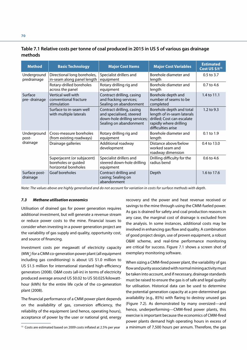
70
7.3 Methane utilisation economics 15
Utilisation of drained gas for power generation requires additional investment, but will generate a revenue stream or reduce power costs to the mine. Financial issues to consider when investing in a power generation project are the variability of gas supply and quality, opportunity cost, and source of financing.
Investment costs per megawatt of electricity capacity (MWe) for a CMM co-generation power plant (all equipment including gas conditioning) is about US $1.0 million to US $1.5 million for international standard high-efficiency generators (2008). O&M costs (all-in) in terms of electricity produced average around US $0.02 to US $0.025/kilowatt-hour (kWh) for the entire life cycle of the co-generation plant (2008).
The financial performance of a CMM power plant depends on the availability of gas, conversion efficiency, the reliability of the equipment (and hence, operating hours), acceptance of power by the user or national grid, energy
15 Costs are estimated based on 2009 costs inflated at 2.5% per year
Table 7.1 Relative costs per tonne of coal produced in 2015 in US $ of various gas drainage methods
Method Basic Technology Major Cost Items Major Cost Variables Estimated Cost US $/t15
Underground predrainage
Directional long boreholes, in-seam along panel length
Specialist drillers and equipment
Borehole diameter and length
0.5 to 3.7
Rotary-drilled boreholes across the panel
Rotary drilling rig and equipment
Borehole diameter and length
0.7 to 4.6
Surface pre- drainage
Vertical well with conventional fracture stimulation
Contract drilling, casing and fracking services;Sealing on abandonment
Borehole depth and number of seams to be completed
1.4 to 11.1
Surface to in-seam well with multiple laterals
Contract drilling, casing and specialised, steered down-hole drilling services; Sealing on abandonment
Borehole depth and total length of in-seam laterals drilled; Cost can escalate rapidly where drilling difficulties arise
1.2 to 9.3
Underground post- drainage
Cross-measure boreholes (from existing roadways)
Rotary drilling rig and equipment
Borehole diameter and length
0.1 to 1.9
Drainage galleries Additional roadway development
Distance above/below worked seam and roadway dimension
0.4 to 13.0
Superjacent (or subjacent) boreholes or guided horizontal boreholes
Specialist drillers and steered down-hole drilling equipment
Drilling difficulty for the radius bend
0.6 to 4.6
Surface post- drainage
Goaf boreholes Contract drilling and casing; Sealing on abandonment
Depth 1.6 to 17.6
Note: The values above are highly generalised and do not account for variation in costs for surface methods with depth.
recovery and the power and heat revenue received or savings to the mine through using the CMM-fueled power. As gas is drained for safety and coal production reasons in any case, the marginal cost of drainage is excluded from the analysis. In some instances, additional costs may be involved in enhancing gas flow and quality. A combination of good project design, use of proven equipment, a robust O&M scheme, and real-time performance monitoring are critical for success. Figure 7.1 shows a screen shot of exemplary monitoring software.
When sizing a CMM-fired power plant, the variability of gas flow and purity associated with normal mining activity must be taken into account, and if necessary, drainage standards must be raised to ensure the gas is of safe and legal quality for utilisation. Historical data can be used to determine the potential generation capacity at a pre-determined gas availability (e.g., 85%) with flaring to destroy unused gas (Figure 7.2). As demonstrated by many oversized—and hence, underperforming—CMM-fired power plants, this exercise is important because the economics of CMM-fired power plants demand high operating hours in excess of a minimum of 7,500 hours per annum. Therefore, the gas

71
Figure 7.1 CMM power generation and abatement: real-time performance monitoring showing the flow diagram and performance parameters of CMM used in three gas engines and one flare
(Courtesy of Formac Electronics and Sindicatum Sustainable Resources)
Figure 7.2 Methane flow and purity fluctuations of drained CMM showing the optimised capacity and use of engines and flare
(Courtesy of Sindicatum Sustainable Resources)
engine capacity should not be designed to utilise peak load gas supply but rather be designed for a continuous base load in terms of gas availability. Peaks flows should ideally be destroyed by flaring to maximise environmental benefits.
As gas capture is progressively improved, further engines can be added; a pure methane flow of 4 m3/min will support about 1 MWe.
Besides the utilisation option of CMM-fired power generation, a wide range of other options exist, such as use of CMM as town gas, in boilers to produce heat, and as feedstock for chemicals as discussed in Chapter 6. In those cases, the economics depend largely on the individual circumstances and a more generalised view as with power generation is difficult.
As the majority of methane emissions from coal mines are in the form of VAM, some principles of VAM utilisation are

72
warranted. VAM oxidation releases heat, which can be used to produce steam and generate electricity. VAM oxidation units with a capacity of 35 normal cubic metres per second (Nm3/s) ventilation air containing 0.5% methane could generate about 1.3 MWe. In order to achieve constant power output, a source of drained CMM is needed to stabilise the VAM concentration and a relatively high VAM concentration is required to optimise performance. The capital cost per unit of power produced is more than twice that of conventional CMM power generation, and there is an “environmental opportunity cost” with respect to emissions abatement four to five times larger than could have been achieved with a similar level of investment. At present electricity prices, and in the absence of high feed-in tariffs, VAM power generation is not commercially feasible without securing a longer-term flow of carbon revenues. In addition, improvement of gas drainage can increase CMM power generation at a much lower cost, thus reducing VAM emissions.
The economics of any use of CMM or VAM for power generation highly depends on the electricity price achieved for a particular project and the value of emission reduction credits or other incentives, e.g., tax exemptions.
7.4 Carbon financing and other incentives
Emission reduction credits (ERCs) can provide an additional financing option in a number of countries, regions, or provinces and can supplement conventional forms of
project financing that may be obtained through bank loans or by private equity investment. There are a variety of operating and planned GHG emissions cap-and-trade or similar programmes in coal mining countries such as Australia, Canada, China, European Union, Kazakhstan, Mexico, and the United States. In addition, many voluntary GHG programmes allow CMM as an offset project type. In the United States, the California Air Resources Board (CARB) approved the latest CMM offset protocol on April 25, 2014, which includes emission reductions through 2020 at active and abandoned underground coal mines as well as open cast coal mines. In China, CMM utilisation projects in Guizhou province were approved as new China Voluntary Emission Reduction Projects by the NDRC on June 4, 2014. The CCERs (Chinese Certified Emission Reductions) produced by these projects can be used as offsets in some of the seven pilot ETS which are operational in China. 16
The carbon offset project cycle begins with the listing and registering of projects with a GHG programme or registry. All registered offset projects must demonstrate they are real, measureable, and verifiable. For some projects, such as China Voluntary Emission Reduction Projects, a robust proof of “additionality” is required to qualify for emission reduction credits using “project-based” methodologies like those in CDM. This effort requires a project-specific demonstration of additionality by showing the project needs emission reduction credits to overcome certain barriers (i.e. technology, financial, and common practice), or otherwise it would not be built. Typically, project eligibility and additionality is established during the validation phase of the project cycle and represents a cost in time and in expense to the project developer.
Alternatively, GHG programmes can use a standardised “performance-based” or “activity-based” method for offsets. Thus, the need for project-by-project additionality arguments and validation costs is removed. Establishing standardised methods involves more up-front expenditure on research and analysis by the GHG programmes and stakeholders, and can be difficult to establish across broad geographic regions with varying coal mining practices. The Climate Action Reserve (CAR) and CARB programmes use standardised activity-based approaches for U.S. coal mines.
16 As of publication of this edition of the Best Practice Guidance, only pilot projects were in operation. In September 2015, China announced that a nationwide emissions trading scheme would be launched in 2017 with full implementation by 2020.
CMM utilisation and methane emissions mitigation at three large coal mines-China
Situation: Three large mines with a combined coal produc-tion capacity of 14Mtpa were capturing a total of around 140 m3/min methane which was being vented to the atmosphere. The mines wished to install modern gas-engine technology and maximise power generation yet they had no experience of CMM utilisation. There were also issues of variable methane concentration and flows at the mines.
Solution: The mining company partnered with an interna-tional project developer with CMM expertise to build and op-erate CMM co-generation projects at three gassy coal mines. The international partner financed all the equipment while the Chinese mining partner provided land and financed the design and civil works. All three projects were successfully registered as CDM projects under the UNFCCC and avoid in to-tal over 1 million tonnes carbon dioxide equivalent annually.
Please see case study 6 for more information.

73
Other incentives to help finance methane utilisation projects include grants, tax credits, green investment schemes (GIS) and feed‐in tariffs (e.g., in Germany and Czech Republic). In the absence of these additional incentives, carbon finance has been proved an effective market-based instrument to trigger the implementation of CMM projects, particularly those involving methane destruction–only, such as VAM. Pay-for-performance is also gaining traction as a policy tool to incentivise emission reductions, in Australia and at the World Bank, for example17 18.
The basis of the leverage effect that carbon financing can bring is that one unit of emission reduction is equivalent to one tonne of carbon dioxide. The amount of 70 m3 of methane is approximately equivalent to one tonne of carbon dioxide (assuming a global warming potential of 2119). Calculations have to take account of the gains by destroying methane as well as the release of 2.75 tCO2 emitted per tonne of methane combusted. As a rough estimate, 1 MWe of CMM‐fired electricity production capacity installed, using 250 m3/h of pure methane emissions can result in an annual reduction of 30,000 tCO2 emissions. Depending on operating hours and efficiency of the system, this can be more than seven times the emission reduction that a 1‐MWe wind turbine would produce.
Before choosing to take advantage of carbon finance leveraging and/or other incentives, issues to consider include the crediting mechanism, process and transaction costs, time, complexity, local rules, and price uncertainty of emission reduction credits. Registering carbon offsets in compliance GHG registries can be challenging and may require specialist assistance, particularly during the project set-up and initial validation and verification.
17 Australia Emissions Reduction Fund White Paper. http://www.environment.gov.au/system/files/resources/1f98a924-5946-404c-9510-d440304280f1/files/emissions-reduction-fund-white-paper_0.pdf
18 World Bank Pilot Auction Facility http://www.worldbank.org/en/topic/climatechange/brief/pilot-auction-facility-methane-climate-mitigation.
19 The IPCC revised this figure to 25 in the Fourth Assessment Report (IPCC 2007) which is now used in CDM projects; California uses the former value of 21 although this may be revised in the future. Successive IPCC Assessment Reports have revised the GWP of methane steadily upwards as knowledge of climate change mechanisms increase. The Fifth Assessment Report presents GWP values of 28-34 (IPCC, 2014) at the commonly used time horizon of 100 years. Emission reduction protocols tend to lag the IPCC updates and therefore a wide range of values are encountered in the literature.
The CDM implemented under the Kyoto Protocol from 2008-2012 allowed developed countries to develop and claim Certified Emission Reductions (CERs) from application of approved methodologies in developing (non‐Annex 1) countries. This mechanism stimulated the development of 128 CMM projects approved by the National Reform and Development Commission (NDRC) in China from 2005-2012. Not all projects qualified for CERs, and the price for CERs dropped precipitously since 2012 due to lack of demand from the ETS, the only sizeable market for the credits. Nevertheless, the CDM incentives have enhanced development of the CMM industry throughout China bringing international investment, improved gas drainage and advanced methane utilisation technologies. Since 2012 the CDM is no longer applicable to new CMM projects in China. However, China has launched seven independent municipal- and province-level GHG pilot emission cap and trading schemes. Rules for the generation of CCERs are being managed through a process similar to the CDM with the NDRC the final arbiter. The government of China plans to introduce a National ETS in 2016 which should be fully operational by 2020. This, the world’s largest carbon market, could offer substantial opportunities for expanding CMM development throughout China; however, an existing environmental standard which requires that CMM >30% purity is utilised presents an additionality barrier to application of best practice by allowing only low-concentration methane projects to benefit from CCERs. While the government of China plans to reduce reliance on coal by constraining growth of the sector, coal mines will continue to be a major source of GHG emissions for the foreseeable future. In 2014, prices of carbon allowances varied widely between the pilot schemes, ranging from US $3.2-10.5/tCO2e. CCER average price forecasts mostly lie in the range of US $3.2-6.5.
The California Cap-and-Trade Program under the control of CARB provides covered entities (such as power plants) allowances to emit GHGs. CARB has recognised CMM emission reductions as a qualifying offset type as long as the project follows the Mine Methane Capture Projects Compliance Offset Protocol.20 This protocol applies to U.S. underground, surface and abandoned mines, although gas pipeline sales from active mines are not eligible because they are considered “business as usual” rather than additional. The first reporting period expires in 2020. Prices for 2014 offsets were reported to range from US $8-
20 http://www.arb.ca.gov/cc/capandtrade/protocols/mmcprotocol.htm

74
10/tCO2e. CARB was officially linked to the Quebec GHG programme in 2014, and has held discussions with GHG programme representatives in Mexico, Kazakhstan, and China.
There are various international voluntary GHG programmes for registering emission reduction projects. Verified emission reductions (VERs) face a smaller market and considerably lower prices (US $1-3/tCO2e) than compliance markets, however, bilateral agreements for as much as US $5/tCO2e were negotiated in 2014.
Several North American-based GHG programmes accept CMM projects. CAR uses an offset protocol for underground mine methane emission reduction for U.S. mines and Verified Carbon Standard (VCS) uses offset protocols for underground, surface and abandoned mines internationally. American Carbon Registry ₂(ACR) accepts international projects using CDM protocols such as ACM0008.
Investment costs for CMM co‐generation plants in terms of emission reduction potential during 10 years of operations are approximately US $3-$5/tCO₂ equivalent avoided. Emission reduction credit generation involves project preparation documents, validation, verification, and service costs, together with the methane utilisation/destruction equipment and its maintenance.
For example, a medium‐level gassy mine (specific emission of 10 m3/tonne of coal mined) earns, net of CO2 produced through combustion, 0.040 CO2/t of coal produced, while
a very gassy mine (specific emission of 40 m3/tonne of coal mined) yields 0.158 tCO₂e/t of coal. This calculation assumes that 40% of the total gas is extracted, of which 80% is utilised. This level of performance would be expected as a minimum for projects where best practice methods and standards are applied and where there are no major geological or mining constraints. In this example if the medium level gassy mine produced 4 million tonnes per year of coal, the tCO₂e mitigated per year would be about 158,000 tCO2e. For a very gassy mine producing 4 million tonnes of coal per year, the tCO2e mitigated would be about 633,000 tCO₂e/year.
The actual value of a tCO₂e mitigated depends on the market and the timing of the sale. The current U.S. (2015) market prices generally range between US $6-$10 per tonne of CO2e. Investment in utilisation at a medium‐level gassy mine (i.e., 10 m3/t) producing 4 Mtpa, with an emission reduction purchase agreement (ERPA) price of US $8/tCO2e (40% gas capture and 80% availability), would yield about US $1.3 million per year from emission reduction credits, plus revenue or cost savings from power generation or gas sales. The captured methane, assuming a stable gas supply, would be sufficient to generate 5 MWe (2.2 million m3 per year of pure methane generates about 1 MWe), and the power revenue at roughly US $0.05/kWh and 7,000 operating hours per year would amount to US $1.75 million. The total revenue from emission reductions and power would therefore equal US $3.01 million. Figure 7.3 shows the modeled revenues in US $/t of coal produced deriving from electricity and ERC sales as a function of the
Figure 7.3 Dual revenues from CMM power generation: 40% gas captured, 80% used
(Courtesy of Sindicatum Sustainable Resources)

75
mine’s specific emissions methane in m3 (pure)/t. Using a midpoint ERC price of US $8/tCO₂e the ERC’s provide about 33% of the total revenue. Using the low and high ERC prices of US $6/tCO₂e and US $10/CO₂e the ERCs would provide 27% and 38% of the total revenues. The economic attractiveness of a CMM power generation project will of course depend on the capital and operating costs of the project.
Substantially higher returns could potentially be earned at higher gas mines. A very gassy mine (40 m3/t specific emission) producing 4 Mtpa would generate revenue of US $8 million from emission reductions and have a 20‐MWe generation potential that could yield US $7 million. Total potential gross revenue is therefore US $15 million. Assuming a typical capital cost for a CMM power plant of say US $1.2 m/MWe installed, payback times of 2 years are feasible.
Financial returns on emission reduction projects are only possible if emission reductions can be proven by providing accurate measurements of methane flow and concentration. Methane drainage and utilisation projects are already—and are likely to become even more so—under scrutiny to provide reliable proof of emission reductions. The complexity of monitoring and measurements are often underestimated and this can lead to safety risks and loss of revenues.
7.5 Opportunity cost of utilisation
A coal mining company might choose to invest in raising coal production capacity as coal prices increase rather than invest in CMM power generation. Conversely, as
coal prices decrease CMM power generation becomes more attractive. The picture changes with third‐party investment in utilisation, supported by carbon financing—an attractive proposition for a mine—as the opportunity cost is obviated and the formerly unused methane creates additional value.
7.6 Environmental costs
At present, most mining companies consider gas drainage to be a mining cost, while costs incurred for gas utilisation or environmental emissions mitigation are classified as an additional investment cost. As climate change mitigation and clean energy recovery become an intrinsic part of the value chain, however, mine operators might need to take a more holistic view of these factors. Mine owners may in the future be required to raise gas drainage performance beyond the safety needs of the mines to meet environmental protection targets.
Under a “business as usual” scenario, estimations for China show that the cost of internalising the methane emission impact of coal mining would be approximately US $12/t of coal production (ESMAP, 2007). No country has attempted to impose such a cost in this magnitude as yet, but the dollar figure provides an indication of the potential cost to a coal mine that fails to minimise environmental emissions. Russia, for example, already imposes a fine on methane emissions from coal mines but far lower than the above figure.


Chapter 8. Conclusions and summary for policymakers
The world has relied upon coal for a significant portion of its primary energy production since the Industrial Revolution. Major emerging, industrialised, and transitional economies—and hence the global economy—will continue to benefit from and be dependent on coal energy resources for the foreseeable future. As of 2013, coal supplied 29% of total global primary energy supply, 41% of global electricity, and over 70% of the world’s steel and aluminum. The International Energy Agency (IEA) projects that global coal production will continue to grow through 2020 despite China’s efforts to moderate consumption, driven largely by demand growth in China and India (IEA, 2015a, IEA 2015b, World Coal Association 2014).
Coal extraction and effective methane management will become increasingly challenging as shallow reserves are exhausted and deeper and more gassy seams are mined. At the same time, societies are increasingly demanding and expecting better environmental outcomes and safer working conditions from the industry.
Ideally, modern coal mining companies recognise the benefits of adopting a holistic gas management system that constructively integrates underground gas control, methane utilisation, and reductions in harmful emissions. Similarly, from policy and regulatory perspectives, a comprehensive approach to CMM management will reap multiple benefits. Establishing and enforcing regulations for safe gas extraction, transport, and utilisation encourages higher methane drainage standards as well as increased clean energy production and greater mine methane emission reductions.
Experience in industrialised countries shows that investment in good gas drainage practices results in less mine downtime due to gassy mine conditions, safer mining environments, and the opportunity to utilise more gas and reduce mine methane emissions. This guidance document should be considered a starting point for devising strategies and developing programmes to support the necessary safety and practice improvements to increase mine safety while dramatically reducing mine methane emissions.
The key principles of this document are as follows:
1. There is tremendous global industry knowledge about and experience with managing methane explosion risks. Global application of the accumulated, currently-available industry knowledge and practices about methane occurrence, prediction, control, and management could significantly reduce explosion risks resulting from methane in coal mines. There is a knowledge gap in managing the gas outburst risk potential. How can gas drainage in very low permeability coal seams be improved?
2. Regardless of constraints, mine worker safety is paramount and should not be compromised. Safe working conditions in gassy mine environments cannot be achieved solely through legislation or even the most advanced technology. Rather, rational and effective management systems, management organisation, and management practices are fundamental to safe operations. Other critical elements of mine safety are appropriate education and training for both management and the workforce, and encouraging worker input as work safety practices are adopted and reviewed.
3. A risk assessment approach to minimising explosion risks should be combined with strong enforcement of robust ventilation, gas monitoring and utilisation safety regulations. This approach will lead to improved gas drainage quantities and qualities. Methane gas flows into coal mines under normal, steady-state conditions are generally predictable. Unusual emission and outburst events are not easily predicted, but the conditions under which they can occur are reasonably well-known. Detailed methods for reducing risks under these conditions have been developed and should be applied wherever significant risks are identified. In such circumstances, safe working conditions depend on the rigor of implementation and monitoring of gas control methods. The importance of not only installing underground monitoring for operational mine safety reasons but gathering and using the data for safety planning cannot be overstated.

78
4. Mine ventilation systems are critical components of an overall system to effectively remove methane from mine workings. A mine ventilation system is designed to achieve three objectives: 1) deliver breathable fresh air to the workers, 2) control mine air temperature, and 3) effectively dilute or remove hazardous gases and airborne respirable dust.
5. Improvements to methane drainage systems can often provide a more rapid and cost-effective solution to mine gas problems than simply increasing the mine’s air supply. Practical gas drainage problems at coal mines can generally be resolved by applying existing knowledge and techniques. Introducing new or novel technologies should only be considered after application of good practices, and only if existing techniques have failed to provide a satisfactory solution. Methane drainage system performance can be improved through proper installation, maintenance, regular monitoring, and implementation of systematic drilling plans.
6. Transporting methane-air mixtures at concentrations in or near the explosive range in coal mines is a dangerous practice and should be prohibited. Methane is an explosive gas in concentration ranges of 5% to 15% methane in air. As a general rule of thumb, a safety factor of at least 2.5
from the low end and 2.0 from the high end of this range should be strictly observed.
7. Underground coal mines are a significant source of anthropogenic methane emissions (about 8% of human-related global methane), but these emissions can be substantially reduced through implementation of best practices. Methane has a GWP 28-34 times higher than carbon dioxide, the most important GHG globally. Much of the methane produced from underground mines can be recovered and used productively or destroyed (mitigating its global warming effect by converting it to carbon dioxide). Options include energy recovery of the drained gas, flaring excess drained gas, and use or abatement of VAM. With the right technical and market conditions, the ultimate goal should be near-zero methane emissions.
8. There is a strong business case for installing and operating high-efficiency gas drainage systems and utilising the captured gas. There is a wide range of potential CMM end uses that have been commercially and profitably employed globally. The high costs associated with purifying drained gas to improve the methane concentration for a particular end use can often be avoided by improving underground methane drainage practices.

79


Chapter 9. Case studies
The following case studies provide readers with examples where the best practices discussed in this guidance document have been implemented at operating mines around the world (Table 9.1). The serious consequences of failing to adopt best practices are also highlighted.
Case studies 1-3 discuss the assessment, planning, and methane management practices implemented at three longwall mines to address methane control problems. Case study 4 demonstrates how effective management systems can ensure safe working of outburst prone coal seams.
Case studies 5 & 6 show how methane drainage performance can be improved and CMM utilisation and abatement can be successfully combined to virtually eliminate emissions of drained gas to the atmosphere.
Case studies 7 & 8 focus on VAM abatement and utilisation.
Case study 9 addresses the reduction of explosion risks in
room-and-pillar mines and Case study 10 illustrates the
tragic consequences of failure to adopt best practices.
The case studies are necessarily brief and are intended to
highlight key points in each case.
Case study 1: Achieving planned coal production from a gassy, retreat longwall with severe strata stress and a spontaneous combustion prone coal seam – United Kingdom
Initial conditions: 980 m working depth, 50 m3/t specific
emissions from a 2 m high retreat longwall required to
produce 1 Mtpa, high spontaneous combustion risk coal,
ultra-low permeability coal, severe horizontal stresses
at the coalface and floor heave in the longwall access
roadways—one intake and one return.
Table 9.1 List of case studies
No. CountryCoal
production efficiency
Ventilation control
Gas capture
& controlGas use Emission
mitigationExplosion
prevention Note
1 United Kingdom Y Y
2 Germany Y Y Y
3 Australia Y Y Y Power generation Use/Flare Yes Outburst
Prevention
4 Australia Y Y Y Outburst prevention
5 China Y CMM power & heat Use/flare
6 China Y CMM power & heat Use/flare
7 China VAM heat VAM
8 Australia VAM power VAM
9 South Africa Y Y Room & Pillar Mining
10 New Zealand Lessons learned

82
boreholes behind the face in a specially supported and ventilated “back-return” (Figure 9.1). The optimum drilling pattern was found to be a series of up-holes, at right angles to the longwall roadway, angled upwards at 55o to the seam plane, and 7.5 m apart. Down-holes were drilled 100 m apart to minimise floor emission risks.
Two drainage collection pipes were installed in parallel. Boreholes were progressively connected to one of the pipes until the gas quality declined; that pipe was then
Gas control problems: Predrainage was not feasible due to the low permeability of the coal, and cross-measure boreholes angled above the longwall front of the face were disrupted by the high stresses; hence, gas capture and purity was too low. The high spontaneous combustion risk and a large pillar size requirement for stability precluded use of multi-entry or bleeder road systems.
Solution: The requisite production was achieved using the available 30 m3/s of ventilation air by drilling cross-measure
Figure 9.1 Back-return system
(Courtesy of Green Gas International)
Figure 9.2 “Leapfrog” system
(Courtesy of Green Gas International)
Broken and sheared-off boreholes
Crushed and leaking pipe ranges
Closed valves
Open valve
“A” and “B” pipe ranges
8 to 16 Active boreholes, high purity, high flow
Last completed borehole, high purity increasing flow
Limit for safe entry to goaf

83
regulated to prevent excessive dilution of the gas and boreholes were subsequently connected to the other collection pipe. This “leapfrog” process was continued, allowing at least eight boreholes to remain connected to the gas drainage system at any time (see Figure 9.2). The coarse regulation was sufficient to optimise gas quality and quantity and a capture rate of 67% was achieved without requiring personnel to venture into the hazardous goaf to adjust individual boreholes.
The rate of retreat of the longwall was very rapid, and the space available for drilling operations was limited, so each borehole had to be drilled, the standpipe installed and sealed, and connected to the drainage collection pipe within an approximately 10-hour cycle. This was achieved using a small, portable and powerful drilling machine (Figure 9.3) powered from the hydraulic circuit of the longwall powered roof supports to obviate the need for electricity.
Figure 9.3 Cross-measure drilling rig
(Courtesy of EDECO Ltd.)

84
Case study 2: High performance longwall operations in areas with high gas emissions – Germany
Initial conditions: In a seam of 1.5 m thickness, a longwall with a length of 300 m, and a planned production of 4,000 tonnes per day (t/d), and a face advance rate of about 50 m/week. The overburden depth is 1,200 m, the seam near horizontal, and there are no previous workings to partially degas the coal seams. Gas predictions indicated likely specific gas emissions of 25 m³/t from the roof, 3 m³/t from the worked seam, and 8 m³/t from the floor (in total 36 m³/t). The coal was known to be prone to spontaneous combustion.
Gas control problem: The maximum methane flow that must be captured or diluted by ventilation to a safe concentration is 1.875 m3/s (112.5 m3/min). Predrainage was evaluated and determined to be ineffective. There were two main constraints. Firstly, a maximum permissible airflow of 25 m3/s across the longwall coalface could only dilute a maximum gas inflow of 0.37 m3/s (22.2 m3/min), despite a relaxation by the mining authority which raised the maximum permitted methane concentration from 1.0% to 1.5% (a reduction in factor of safety from 5.0 to 3.3). The latter change was conditional on enhanced monitoring and gas drainage. It is important that such changes are only made on a site-specific basis and additional measures taken to ensure no significant increase in risk. The second constraint was the airway into which the district ventilation air was to discharge, in which a maximum of 1% methane is permitted.
Solution: A Y-ventilation system (Figure 9.4) was designed to introduce a further 50 m3/s of air and add to the 25 m3/s passing across the face, the combined flow passing behind the face diluting the methane emitted from the coalface and the goaf. The ventilation configuration allows cross-measure boreholes to be drilled, connected to the drainage system and individually monitored and regulated—generally cross-measure boreholes drilled behind the longwall face achieve higher captures and maintain higher gas purities than those drilled in front of the coal face. These drainage holes have a long lifetime and high effectiveness, and are expected to capture 70% of the roof gas and 40% of the floor gas.
Seals (pack wall) on the goaf side of the open roadway behind the face served to enhance roadway support and isolate the goaf from air ingress to minimise spontaneous combustion risk and from creating methane concentrations in the explosive range.
The limiting concentration of 1% outbye of the return ultimately limited the coal production to 4,000 t/d, which was in accordance with the planned target. About 80,000 m3/d of pure methane could be extracted by the gas drainage system and utilised in a power station. Despite the severity of the mining conditions, the longwall was a success due to the advanced ventilation design and the highly effective gas drainage.
Figure 9.4 Longwall with Y-shaped, advanced ventilation design and drainage boreholes in the roof and the floor behind the longwall
(Source: DMT GmbH & Co. KG)

85
Case study 3: High performance longwall operations in areas with high gas emissions – Australia
Initial conditions: A new series of longwall blocks is located in a 2.8 m-high seam with methane contents ranging from 8 to 14 m3/t. Depth of cover is 250 m to 500 m with surface access generally unconstrained by surface features. In situ gas content must be reduced to or below 7.5 m3/t to satisfy the outburst prevention code. There is a single floor seam and eight roof seams containing 10 m to 15 m of coal within the nominal caving zone. Longwall blocks are 350 m wide and up to 3.6 km in length (Figure 9.5), with a planned production rate of 200,000 tonnes per week.
High potential gas emission values led the mine to develop three-heading gate roads on longwalls from the outset in order to provide a high volumetric capacity ventilation system for gas dilution. A three-heading gate road allows substantially more air to be provided for gas dilution to the return end of a longwall face, without increasing face air velocities, compared with a conventional U-ventilated system. This is currently the only mine in Australia to employ three-heading gate roads.
Gas control problems: Gas emission predictions indicate likely specific emissions of 15 to 30 m3/t from coal seam sources. At planned production rates, this would equate to 3,500 to 7,000 l/s CH4, generally increasing with depth. However, previous studies at an adjacent mine demonstrated substantial extraneous gas which could significantly increase the total emission rates. Emissions from the first three longwalls were controllable within the existing design but were higher than expected for the relatively shallow depths. Extrapolation to the deeper longwalls indicated feasibility stage predictions would be exceeded with emissions possibly reaching 9,500 l/s.
Solutions: Development phase outburst and frictional ignition limits are reached using a combination of surface to inseam medium radius drilling (MRD) techniques supplemented with underground directional holes and compliance holes that are cored for gas content testing. The initial pit bottom area was pre- drained with tight radius drilling (TRD) techniques.
The original plan to employ three-heading gate roads was correct in providing a longwall ventilation circuit capacity of 100 to 120 m3/s (2,000 to 2,400 l/s CH4 at
Figure 9.5 Mine layout plan showing ventilation and gas drainage systems
(Source: Belle, 2016)

86
the return limit of 2.0%). It is important to note that, following the Moura disaster of 1994 where 11 miners died, coal mine regulations, guidelines, and custom and practice in Queensland prevent mines from employing a full U.S.-style flood ventilation bleeder system. However, controlled bleed with due consideration to the location of potentially explosive mixtures and control of spontaneous combustion is possible.
The realistic dilution capacity of a bleeder system in these blocks is well below total longwall gas emission rates and alternative strategies are required. To date, the mine has successfully employed conventional surface to goaf drainage holes (300 millimetre diameter at 50 m spacing located on the tailgate return side) to reduce the gas emission load on the ventilation system. This strategy has achieved an average 80% capture (goaf drainage plus ventilation) with peaks of about 85% at high gas stream purity (>90% CH4).
The gas collection infrastructure is on the surface, using 450 millimetre diameter pipes, including that from vertical connections to underground directional holes. All surface gas streams from underground predrainage, surface MRD predrainage, and goaf holes are exhausted to a mobile goaf drainage plant and central pump station from where about 2,200 l/s of gas is discharged to 16 x 2.0 MW gas engines with the balance flared. The site policy is to avoid direct discharge of captured gas if at all possible.
Recognising that, in future blocks, gas emission to ventilation net of 85% goaf capture will still prove problematic for the ventilation system, the mine is now attempting to also pre-drain thicker roof target seams using approximately 2.0 km long holes drilled along longwall axes. These holes will serve initially as predrainage and after under-working as goaf drainage holes targeting close face gas emission. Conventional multiple seam completion frack wells may also be considered should additional predrainage be required above future deeper workings.
Case study 4: Safe mining of an outburst-prone coal seam – Australia
Initial conditions: Over 700 outbursts of coal and gas involving carbon dioxide and methane in varying mixtures had been recorded in Australian mines since 1895, some causing fatalities.
Problem: A particularly problematic outburst prone seam was the Bulli, which was being worked by a number of
mines in New South Wales (NSW). Since the first recorded outburst around 1895 there have been 12 fatalities resulting from outbursts. Following an outburst-related fatality at South Bulli Colliery in July 1991, a number of industry working groups were formed at the initiative of the mines inspectorate to examine the risks. The analysis led to the introduction of the concept of Outburst Management Plans (OMP). Application of OMPs proved patchy and an outburst-related fatality at Westcliff Colliery in 1994 highlighted the need for a more stringent approach. The procedures that were successful in high methane areas have failed in some mines to produce positive results in high carbon dioxide areas. Concentrating coal production on fewer high production longwalls demanded faster heading development rates. In this situation, it was essential to control outburst and gas emission risk to maintain the viability of mining operations.
Solution: The NSW mines inspectorate sought to address the deficiencies by issuing a practical guide, which explained to mine management how to develop and implement a rigorous outburst management system. The need for this approach is reflected in the following statement from the Outburst Mining Guideline (Department of Mineral Resources, NSW, 1995):
“The extensive experience of the Coal Mining Inspectorate in the investigation of outburst events has shown that a degree of certainty is often lacking in knowing that procedures intended to be undertaken are, in fact, undertaken. In other words, it has become apparent that the management of outburst risk is at least as much a managerial and control issue as it is a technical issue. The best technology available has often been found wanting in the absence of effective systems to control its application”.
The Outburst Management Plan (OMP) must describe responsibilities, procedures and protocols to facilitate safe working. The outburst management process involves analysis of seam gas content monitoring, geological structure and results of in-seam drilling. Gas drainage is the principal prevention mechanism by reducing gas contents in the worked seam below a threshold concentration considered as the minimum to pose an outburst risk (Lama, 1995). Procedures for mining under outburst conditions are implemented when it becomes apparent that no further mitigation is possible or further drilling will not provide meaningful additional data. Outburst mining procedures are designed to minimise the exposure of workers to the hazard and to provide emergency protection facilities in the areas at risk.

87
Subsequently, coal mines in Australia have demonstrated that with effective management systems in place outburst prone seams can be mined safely and profitably.
Case study 5: Development of a CMM power co-generation/emission abatement scheme – China
Initial conditions: A new surface gas extraction plant had been installed and completed in May 2007 at a remote 1,600 m mountain location above a coal mine with a coal production capacity of 5 Mtpa, a specific emission of 17.7 m3/t, and draining methane at an average pure flow of 22 m3/min. The overall mine methane capture efficiency was 15%, the remaining 85% being emitted with the ventilation air.
Gas control problems: Gas purity at the extraction plant was variable and sometimes less than the 30% minimum permitted for utilisation and gas capture efficiency. Drained gas quantities were expected to fluctuate due to variations in the longwall mining cycle and the phasing of workings in different seams; therefore, the CMM power plant capacity needed to be sized to ensure 85% availability to meet investment requirements. An aim of the project was to optimise energy recovery and minimise GHG emissions. An integrated engine and flare system was required—a first in China; therefore, technology transfer demands were expected to be high.
Solution: A team of local and international specialists in gas drainage and power and systems engineering were applied to the project to work with the mine staff to ensure gas delivery, scaling of project size, and plant integration and performance.
Methane purity was raised by improving the sealing and regulation of cross-measure boreholes. The gas capacity of the drainage infrastructure was increased, high-resistance flow monitoring devices were replaced, and a plan prepared for increasing gas capture. Intensive predrainage drilling on two future longwall panels provided enrichment gas and also supplemented flow eventually contributing 23% of the drained gas, the remainder coming from postdrainage, roof cross-measure boreholes. The latter were drilled ahead of the face and inevitably some suffered damage and performed badly once in the goaf. A demonstration borehole was drilled over the goaf behind the face, which performed well but the technique has not yet been adopted for local regulatory reasons, and this method of drainage has not been historically practiced in this region.
Phase 1 of the scheme involved installation of 5 MWe with waste heat recovery for heating buildings and intake ventilation air in winter. A nominal 5,000 m3/hour flare was also installed. A specialist company was engaged to devise and install a remote performance monitoring system for the utilisation and destruction equipment.
Once gas capture had been demonstrably increased to more than 50 m3/min (pure), construction of Phase 2 was implemented in October 2009 to raise the power generation capacity to 12 MWe.
Case study 6: CMM utilisation and methane emissions mitigation at three large coal mines – China
Initial conditions: Three large mines with a combined coal production capacity of 14 Mtpa located close to Taiyuan, the provincial capital of Shanxi Province, China, were capturing a total of around 140 m3/min methane which was being vented to the atmosphere. There was scope for further increasing CMM capture at the mines. National, provincial and company policy was to seek a means to harness CMM to produce clean energy and to mitigate greenhouse gas emissions. High and rising power prices provided a major incentive for coal mines to generate electricity for self-use.
Utilisation and mitigation problems: The mines wished to install modern gas-engine technology and maximise power generation yet they had no experience of CMM utilisation. There was a corporate desire to identify and implement best practice gas extraction, use and mitigation employing imported technology. However, difficulties were envisaged with financing, operating and maintaining foreign equipment. Too often in the past technology that had been imported into China fell into decay through lack of operational expertise and failure to invest in preventive maintenance. There were also issues of variable methane concentration and flows at the mines to resolve.
All the project sites were located in mountainous areas, the highest at an altitude of 1600 m, and subject to weather extremes with snow in winter and high midday temperatures in summer. Construction could therefore not be carried out safely or effectively in winter and operational equipment would need to function reliably under a wide range of climatic conditions.
Solution:
Project construction. A major State-owned coal mining company and its operating subsidiary partnered with an international project developer to build and operate CMM

88
co-generation projects at three gassy coal mines. The projects were to be CDM registered under the UNFCCC. The international partner financed all the equipment while the Chinese mining partner provided land and financed the design and civil works. Each project required the preparation and government approval of a feasibility study prior to final design and implementation. Government regulations in China restrict design activities to specialist, certified institutes. The project developer’s engineering team worked with the Chinese design institutes to help them understand the new technologies being introduced and also to encourage adoption of western standards, especially with regard to health and safety. Environmental impact assessments were prepared, reviewed and officially approved prior to construction.
After approval, a public bidding process for supply and installation of the project equipment under an Engineering Procurement Construction (EPC) type contract was initiated. Technical detail was then discussed with the preferred bidder and final terms agreed. Due to severe winter conditions, construction was only feasible for 8 to 9 months of the year. The implementation schedule is summarised in Table 9.2.
The platforms for the CMM project sites were formed by cut and fill in hilly terrain with poor soil conditions. Engines were accommodated in containers which prevent noise pollution and assure that the engine combustion emission controls meet the latest standards.
The CMM co-generation project at coal mine T suffered serious delays due to landownership issues compounded by a serious underground explosion in February 2009 that fully occupied both mine and group management for a substantial period of time. Later, a protracted engine warranty dispute meant the full capacity of the plant was not realised for almost two years after completion. The local designers included a large gas-holder to buffer CMM
supply but due to a regulatory issue it remains unused but there has been no measurable impact on project performance.
Initial performance of the power plant at mine M was lower than planned due to insufficient capacity of the gas cooling system which was subsequently rectified.
All three projects were successfully registered as CDM projects under the UNFCCC and avoid in total over 1 million tonnes carbon dioxide equivalent annually. Emission verifications have been completed successfully at all the sites and will continue for the 10-year life of the projects. Over 30 MWe of electrical generation capacity has been installed and further expansion of project T is being considered. Some 65 new jobs have been created in poor mining areas to the benefit of local economies together with improvements in local infrastructure.
Engineering issues and solutions. Technology transfer was an essential component. Investment and technical assistance was provided by an international project developer with an experienced mining and engineering team. Nevertheless, there was some resistance to new ideas especially where there was conflict with existing, but often outdated, design practices and rules.
The power plants were constructed in phases to build experience in operation of sophisticated foreign gas-engines and to allow time for improvements in gas capture and quality at the mines (Figures 9.6 and 9.7). Training was given by the technology providers and technical support services were available from the project developer’s office in Taiyuan within short driving distance of all the sites. Additionally, a proprietary remote monitoring system was developed to facilitate a rapid response to fault warnings and optimisation of emission reductions.
Suitable protection against climate extremes was devised to ensure that pre-treatment systems, engines, monitoring
Table 9.2 Implementation schedule
Activity Mine D Mine T Mine M
Co-operation agreement between partners signed August 2007 March 2008 March 2008
Site preparation started June 2007 June 2009 March 2009
Phase 1 power generation commenced May 2008 June 2011 August 2010
Phase 2 power generation commenced November 2010 Expected September 2016 November 2014

89
and control systems function under all weather conditions. Nevertheless, the challenging conditions during summer and winter periods can limit gas-engine loads and increases the maintenance downtime periods.
The international mining team worked with the project mines to raise gas management standards and to ensure methane concentrations consistently above 30% for safe gas capture, transport and utilisation. In the absence of a national Chinese standard, the international team developed an operational guidance document for the surface CMM plants. Principal improvements at the mines resulted from attention to drainage borehole drilling and regulation, introduction of new methods for dewatering gas drainage pipelines and enhanced suction pressure control at the surface extraction stations.
The overall performance of the projects is summarised in Table 9.3. A target power generation availability of 80% has not been achieved due to factors relating to plant operations, maintenance and CMM supply. CMM gas flow varies with coal production rate and is affected by longwall stoppages due to geological problems, underground longwall face changeovers and mine maintenance activities. Power plant availability is calculated by multiplying the percent of engine running time by the percent of engine load achieved.
CMM projects at the three mines continue to operate as designed despite poor returns from the certified emissions reductions and consistently achieve emission mitigation targets because excess gas from power generation, especially during downtime periods, is destroyed in the flares.
There is potential to improve power generation at the case study sites by further enhancing operational and
maintenance practices – spares availability, preventive maintenance and advanced training for technical staff. Heat recovery systems are only used in the winter (approximately 5 months) for shaft heating at mine D and hot water and space heating at the other sites. All-year round uses for waste heat which are commercially viable have not been identified.
Lessons: This case study shows how modern CMM–fuelled power generation, heat recovery systems and flaring units can be integrated into a system in which virtually all of the drained gas can be used or destroyed - a key step towards near zero emissions mining. The benefits to coal mines are power savings and substitution of clean energy from waste heat recovery for water, space and shaft heating previously provided by polluting coal burning boilers.
High power prices alone may not be sufficient to encourage investment in state-of-the-art CMM utilisation. Carbon financing linked with technology transfer was demonstrated to be an effective driver in this case study.
The amount of time required to obtain necessary consents and approvals for a CMM project should not be under-estimated. Project timing and schedules must take account of the impracticality and hazards of working in extreme winter conditions. Equipment and installations must also be designed to operate satisfactorily in all weather conditions likely to be encountered.
Mines introducing technologies with which they are not familiar with must have ready access to technical support and specialist services in the locality of the project sites. Equipment performance depends not only on its initial specification and installation but also on how it is operated and maintained.
Table 9.3 Summary of CMM project performance
CMM project
coal mine
CDM project UNFCCC
registered
Power generation
capacity MWe (2015)
Flare capacity
m3/h
Typical annual
power export MWh
Cumulative power export
to 31 July 2015 MWh
Typical emission reduction tCO2/year
Overall power plant generators availability
Overall availability
of flares
Mine D 9 March 2009 11.9 1 x 5,000 69,300 380,200 385,000 66% 20%
Mine T 17 Dec 2010 12.2 4 x 2,000 62,000 266,900 482,000 59% 90%
Mine M 3 Dec 2010 7.5 2 x 1,500 24,700 Phase 1 only 120,400 192,800 75% 80%

90
Figure 9.6 CMM co-generation power plant phase 1 at mine D
Figure 9.7 Flare system at mine T

91
Table 9.4 Amounts of energy that can be retrieved from an installation processing 250,000 Nm3/h of ventilation air under various conditions
Result of secondary heat exchange At 0.3 % VAM At 0.6 % VAM At 0.9 % VAM- Water at 70 degrees C 1 MW 8 MW 15 MW- Water at 150 degrees C - - Not possible - - 2 MW 10 MWHeat exchange from inside RTOs 3 MW 11 MW 18 MW
Figure 9.8 VAM abatement and energy recovery implemented in China
(Courtesy of Zhengzhou Mining Group, MEGTEC Systems and EcoCarbone)
Case study 7: VAM – China
Abatement of VAM emissions, and generating hot water from the energy released in VAM oxidation.
Initial conditions: A large coal mine located in Henan Province, People’s Republic of China, with a coal production capacity of 1.5 Mta was emitting around 12 million m3 per year of methane. VAM accounted for 56% of emissions with the remaining 44% of methane removed by gas drainage. VAM concentrations varied between 0.3 and 0.7%.
Gas control problems: Utilisation or abatement of VAM emissions had not been previously demonstrated in China because there had been no incentive to undertake such projects in the absence of carbon credits.
Solution: An emerging CDM market provided the financial driver to implement VAM abatement projects. The State-owned mining group worked with a CDM project developer and a leading technology supplier to design, commission and operate a commercial VAM demonstration project utilising a single-bed flameless RTO (Figure 9.8). This was the first validated and registered CDM VAM project within the framework of the Kyoto Protocol.
The first project was intended as a commercial demonstration project, but included the facility to add further VAM units should the mine wish to scale the operation.
The VAM installation at the mine consists of a single RTO
with a throughput capacity of 62,500 Nm3/h (17 Nm3/
sec), which is 17% of the total shaft flow of 375,000 Nm3/
sec. The connection to the mine fan is indirect in nature
so that if the VAM processing installation is stopped, all
ventilation air goes by default to atmosphere. Important
safety arrangement includes sufficient length of ductwork
so that in case of emergency (e.g. if too high concentration
of VAM is detected), there is time to operate a bypass
damper to divert all the flow directly to atmosphere. The
RTO is capable of self-sustained operation within the range
of VAM concentrations produced by the mine. The project
commenced operation in October 2008 and has operated
with a destruction efficiency of 97%. CER production
is dependent on the quantity of methane destroyed,
typically avoiding between 20,000 tonnes (0.3% CH4) and
40,000 tonnes (0.6% CH₄) of CO₂ equivalent per year for the
single unit. When methane concentration is below the self-
sustaining level of 0.2% the system is shut down.
VAM utilisation: The installation at the Zhengzhou mine
is generating hot water for miners’ showers and for heating
of nearby buildings. The heat recovery is achieved by the
application of an air-to-water heat exchanger installed
between the RTO and its exhaust stack, recovering the
energy in the heated exhaust air.

92
Table 9.4 compares amounts of energy that can be retrieved by secondary heat recovery of the RTO exhaust air in the form of water at 70 degrees C and 150 degrees C, respectively, at various VAM concentrations. The table also indicates the amount of energy that can be recovered by primary heat exchange, tapping the energy from directly inside the RTO(s). The generation of thermal energy is linear. Two units of the RTO would therefore generate twice the amount of thermal energy.
Case study 8: VAM – Australia
Abatement of VAM emissions, and utilising the energy released in VAM oxidation to produce superheated steam to drive a conventional steam turbine power plant.
Initial Conditions: VAM from a major colliery in New South Wales, Australia was being emitted to the atmosphere in concentrations around 0.9% CH4. In addition, drainage gas with a concentration exceeding 25% was being emitted to atmosphere near the evasée.
Gas Control Problems: Large-scale VAM utilisation or abatement had not been previously demonstrated anywhere in the world due to the nature of the emission with very large air flow and extremely dilute methane concentration. Small-scale VAM utilisation or abatement had been applied in a 12-month long demonstration from 2001 to 2002 at the Appin Colliery of BHP Billiton in Australia. There, a small-size RTO had been processing VAM and utilising the energy released to generate steam—demonstrating long-term capability of handling the natural changes in VAM concentrations and long-term efficient energy recovery.
Solution: Working with the manufacturer of the RTO used at the Appin Colliery, the mine integrated four RTOs into the steam cycle of a steam-based power plant, effectively using the RTOs as special furnaces capable of operating on the extremely dilute fuel of VAM (Figure 9.9). The mining company received substantial grant funding from government sources to implement the project.
Figure 9.9 VAM abatement and energy recovery for the generation of electricity
(Courtesy of MEGTEC Systems and Illawarra Coal Division of BHP Billiton)
The VAM-fuelled power plant (Figure 9.10) is designed to process 250,000 Nm3/hour (150,000 standard cubic feet per minute or scfm) of ventilation air, corresponding to 20% of the total volume available in the mine evasée. The power plant design is based on the average VAM concentration of 0.9%. The RTOs are designed to handle variations in VAM concentrations, but for the steam turbine to operate continuously on optimal speed, the energy in the ventilation air processed needs to be kept fairly stable at the design point. At this project site, drainage gas of 25% or higher concentration is injected into the ventilation air flow prior to the process fans when VAM concentration is below 0.9%.
The VAM-based power plant was in full operation by April 2007. Reported power plant availability in the first fiscal year (July 2007 to June 2008) was 96% including two planned maintenance shutdowns. By October 2014, the installation had generated over 1.5 million emission credits and over 240,000 MWh of electricity.
For a successful VAM-fuelled steam turbine power plant:
• VAM concentration should be 0.7% or higher.
• The ventilation air volume available should be minimum 500,000 Nm3/hour (300,000 scfm).
• There should be drainage gas (minimum 25% concentration) available for injection into the
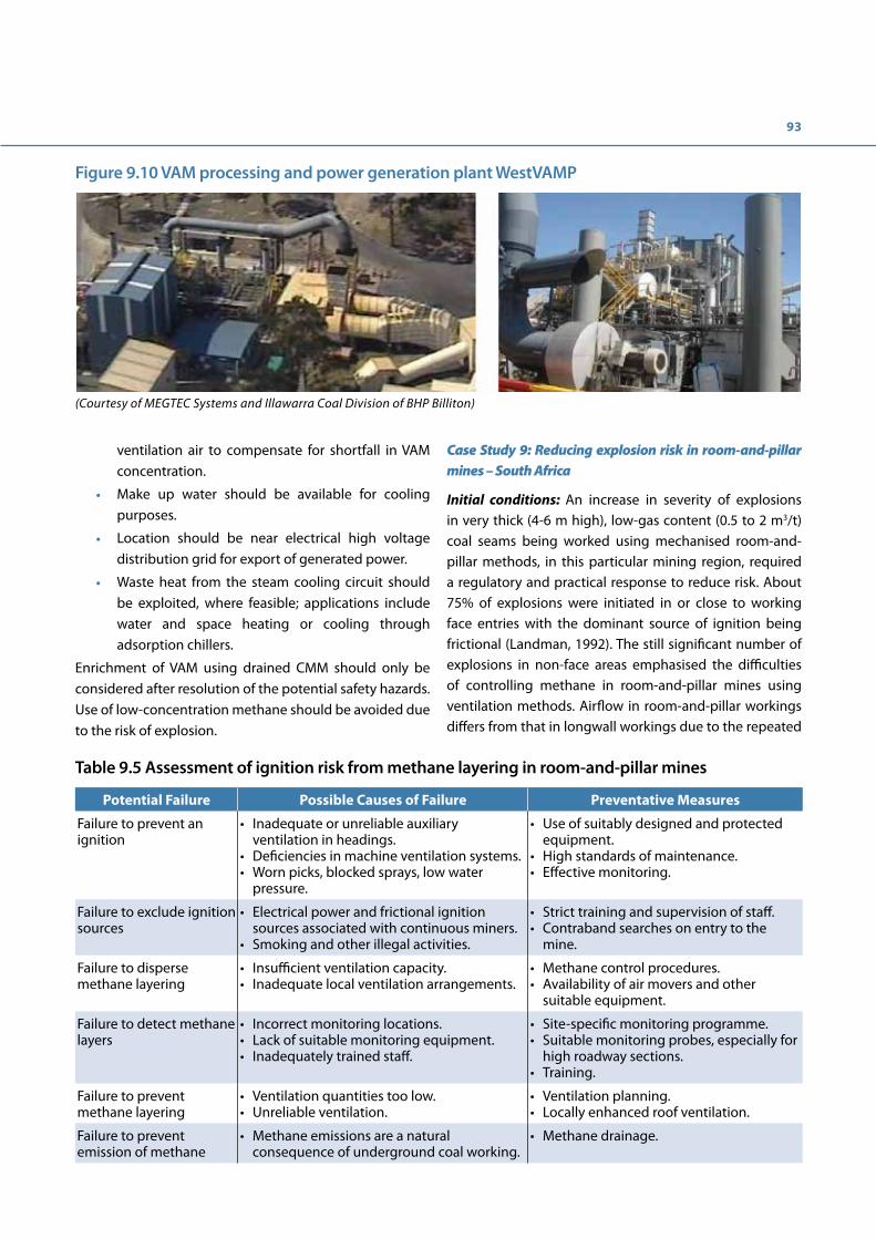
93
ventilation air to compensate for shortfall in VAM concentration.
• Make up water should be available for cooling purposes.
• Location should be near electrical high voltage distribution grid for export of generated power.
• Waste heat from the steam cooling circuit should be exploited, where feasible; applications include water and space heating or cooling through adsorption chillers.
Enrichment of VAM using drained CMM should only be considered after resolution of the potential safety hazards. Use of low-concentration methane should be avoided due to the risk of explosion.
Case Study 9: Reducing explosion risk in room-and-pillar mines – South Africa
Initial conditions: An increase in severity of explosions in very thick (4-6 m high), low-gas content (0.5 to 2 m3/t) coal seams being worked using mechanised room-and-pillar methods, in this particular mining region, required a regulatory and practical response to reduce risk. About 75% of explosions were initiated in or close to working face entries with the dominant source of ignition being frictional (Landman, 1992). The still significant number of explosions in non-face areas emphasised the difficulties of controlling methane in room-and-pillar mines using ventilation methods. Airflow in room-and-pillar workings differs from that in longwall workings due to the repeated
Figure 9.10 VAM processing and power generation plant WestVAMP
(Courtesy of MEGTEC Systems and Illawarra Coal Division of BHP Billiton)
Table 9.5 Assessment of ignition risk from methane layering in room-and-pillar mines
Potential Failure Possible Causes of Failure Preventative Measures
Failure to prevent an ignition
• Inadequate or unreliable auxiliary ventilation in headings.
• Deficiencies in machine ventilation systems. • Worn picks, blocked sprays, low water
pressure.
• Use of suitably designed and protected equipment.
• High standards of maintenance. • Effective monitoring.
Failure to exclude ignition sources
• Electrical power and frictional ignition sources associated with continuous miners.
• Smoking and other illegal activities.
• Strict training and supervision of staff. • Contraband searches on entry to the
mine.
Failure to disperse methane layering
• Insufficient ventilation capacity. • Inadequate local ventilation arrangements.
• Methane control procedures. • Availability of air movers and other
suitable equipment.
Failure to detect methane layers
• Incorrect monitoring locations. • Lack of suitable monitoring equipment. • Inadequately trained staff.
• Site-specific monitoring programme. • Suitable monitoring probes, especially for
high roadway sections. • Training.
Failure to prevent methane layering
• Ventilation quantities too low. • Unreliable ventilation.
• Ventilation planning. • Locally enhanced roof ventilation.
Failure to prevent emission of methane
• Methane emissions are a natural consequence of underground coal working.
• Methane drainage.

94
abrupt expansions and contractions where longitudinal roadways intersect transverse cross-cuts.
The build-up of gases in high production sections with inadequate ventilation and transmission of flame in undetected roof layers of methane (Table 9.5) were considered significant risks which should be controllable (Creedy & Phillips, 1997).
Gas control problems: Ventilation of working faces requires auxiliary ventilation drawing air from the last-through-road. The mined sections comprise an extensive chequer-board of roadways and pillars, all of which cannot be effectively ventilated due to the massive amounts of air required and the difficulty of distributing it evenly. To ensure main ventilation flows reach the working faces, these worked-out areas are closed off with temporary screens; gas can therefore accumulate in the enclosed areas behind the face.
In mines where accumulations of water and methane pressures were identified as a possible cause of roof falls, roof-bolted boreholes were interspersed with open, free-draining boreholes. Some emitted gas at low flow rates that could form extensive methane layers, and would remain undetected unless probed close to roof level, which is difficult in the high roadways.
Solutions: Gas control where partial extraction mining methods are practised can be assisted by in-seam, predrainage; postdrainage is rarely required as roof and floor coal-bearing strata are not significantly disturbed. In low gas-content seams, predrainage is of little benefit. Gas drainage was therefore not a viable option for this region. A practical solution necessitated improving ventilation practice.
It is not practicable to ventilate worked-out sections to the same standard as working sections due to the finite supply of air available. Emphasis in these changed circumstances was therefore directed at the introduction of effective monitoring schedules involving gas detection in the roof and air velocity monitoring in the general body of room-and-pillar workings in which ventilation quantities have been reduced pending sealing-off the area.
The highest risk area was considered to be the working faces and a code of practice for ventilating mechanised sections was developed by the government regulator (Department of Mineral and Energy Affairs, 1994). A fundamental criterion was that flammable gas concentrations should be less than 1.4%, and in order to secure this the following measures were recommended:
• A minimum air velocity in the last-through-road of at least 1.0 m/s (many mines chose to install a continuous, remote velocity monitor).
• Use of effective auxiliary ventilation in headings (secondary ventilation).
• Regular measurement and recording of critical ventilation data.
• Inspections of gassy sections at intervals not exceeding one hour.
• Automatic electrical isolation of mechanical cutting if the secondary ventilation system ceases to operate.
• Special precautions when approaching emission risk zones associated with igneous intrusions and geological anomalies.
• Continuous gas monitoring in the heading being mined.
• On-board scrubbers on continuous mines are now mandatory.
Case study 10: Gas explosions at Pike River coal mine – New Zealand
Initial conditions: The Pike River coal mine is located 46 km NNE of Greymouth on the west coast of South Island, New Zealand. The surface installation and infrastructure was largely complete and had earned an environmental protection award for its sensitive design and implementation (Figure 9.11).
The situation underground was in complete contrast to the surface conditions. Underground mining conditions were difficult, primarily due to unexpected geological conditions resulting in serious mine development delays.
There was pressure for premature coal production. Costs had risen above expectations and financial reserves were dwindling rapidly. In order to generate much needed revenue, a production face was developed and trial coal production started; a hydraulic method of mining was being employed. A main fan was installed underground near to an upcast shaft. The shaft had suffered stability problems and was inadequate as a second means of egress for men in the event of an underground emergency. The only viable entry and exit route for the miners was via a 3 km drift.
Gas had not been considered as a potential hazard. During exploration and development no systematic data had been obtained on the gas bearing and emission characteristics of the coal deposit. Only when gas became a problem was

95
a cursory attempt made at control. Furthermore, electrical equipment in part of the underground mine was not designed and installed to comply with mine explosion protection standards.
Corporate responsibility for occupational health and safety was lacking. The Board of Directors took no active part in health and safety management, deferring to the mine manager on all operational and safety matters. Although there was a safety manager and a safety committee at the mine, both were ineffective. An external study was commissioned which highlighted major safety issues but neither the owners nor the mine manager acted to address any of the safety matters raised. Gas concentrations within the explosive range had been detected on numerous occasions but no action was taken. Due to
unprofessional management, staff turnover was high, leaving unexperienced staff and contractors in charge of underground conditions.
The regulatory system had been reformed removing previous stringent, independent oversight of health and safety at mines throughout the country. The government had restructured its mines inspectorate placing greater reliance on mine management to self-regulate their activities. A combination of a high workload and too few qualified mine inspectors meant that underground visits were rare and regulatory enforcement poor.
The problem: On 19 November 2010 an explosion occurred. In the ensuing days, three further explosions and a fire occurred (Figure 9.12) before the mine atmosphere was made inert and the mine sealed. 29 miners were killed.
Figure 9.11 Surface installations reflect the environmental sensitivity of the area with buildings merging into the forest
Figure 9.12 Fire at the upcast shaft following the third explosion
96
The explosion was not immediately detected at the surface, as alarms in the control room were ignored and the emergency services were not called until 40 minutes later. Two survivors emerged at the surface 101 minutes after the event and there was no one there to meet them.
The Police were responsible for the emergency response but had no mining experience. No emergency drills had been carried out at the mine and there was a lack of data from underground to allow the situation to be properly assessed. As the underground risks could not be established, the Mines Rescue Service was not permitted to enter the mine.
Families of the miners and the community were devastated by the loss. The community was very supportive of the affected families but lack of action by the authorities caused annoyance and frustration. The families campaigned for the mine to be re-entered when safe, to recover the bodies of their loved ones. Although mining experts who were providing technical advice to the families believed safe re-entry was feasible, the national mining company to which the mine was eventually entrusted following the collapse of the Pike River Coal Ltd declined to proceed.
The solution: A solution was required to ensure such a tragedy would not be repeated. Root causes lay beyond the mechanics of what happened in the mine.
A Royal Commission was established to determine and report on the cause of the explosions and loss of life, the effectiveness of search, rescue and recovery and the adequacy of the law and its implementation.
The Commission considered that the management of the incident was far from satisfactory due to:
• Slow initial response by mine management in confirming and reporting the explosion.
• Emergency procedures were neither substantive nor rehearsed.
• Police were responsible for incident control but were unprepared and unqualified to manage.
• In the absence of expert leadership and coordination no attempt could be made to safely enter the mine.
• Families of victims were ill-informed and frustrated by lack of action on recovering the bodies.
There were several possible direct causes of the explosions due to a wide range of possible gas emission and accumulation scenarios combined with the potential
ignition sources including unprotected electrical equipment. Contributory factors which allowed the hazardous working environment to develop unchecked included:
• Financial difficulties due to delays in the development of the mine arising because of geological problems, leading to a call for production revenue prior to completion of the mine infrastructure and proper addressing of safety issues.
• Inadequate ventilation and gas drainage.
• Lack of experienced staff underground.
• No effective worker participation in health and safety.
• No management action despite repeated high gas concentration warnings.
• Ineffective corporate oversight of health and safety.
• Ineffective government mine safety legislation and enforcement.
The Royal Commission published its report on 5 November 2012 in which 16 principal recommendations were made including:
• Significant changes to New Zealand’s health and safety legislation, administration and enforcement were necessary.
• Corporate governance practices should be improved to better manage risks and monitor health and safety compliance within organisations.
• Mine managers should adopt best practice gas control (this UNECE document was cited).
• There should be worker participation in health and safety to provide an additional level of safeguard.
Lessons: The case study demonstrates the importance of having effective, goal-setting regulations supported by inspection and enforcement undertaken by experienced mining professionals. Mine management tasked with delivering production and revenue in challenging situations need an independent check. The responsibility for supervising occupational health and safety performance should start in the Boardroom.
The closure of the Pike River coal mine after the explosion and the failure of the business is a too vivid reminder that accidents are costly and that effective gas management is an absolute necessity in gassy coal mines.

97


99
App
endi
x 1.
Com
paris
ons o
f gas
dra
inag
e m
etho
ds (a
dapt
ed fr
om C
reed
y, 2
001)
Met
hod
Des
crip
tion
Adv
anta
ges
Dis
adva
ntag
es
Pred
rain
age
usin
g ve
rtic
al
surf
ace
bore
hole
s
Invo
lves
frac
turin
g on
e or
a s
erie
s of
co
al s
eam
s us
ing
high
-pre
ssur
e flu
ids
pum
ped
into
a s
urfa
ce b
oreh
ole.
The
fr
actu
res
are
held
ope
n by
inje
ctin
g a
supp
ort m
ater
ial.
Thus
, gas
and
oth
er
fluid
s, ab
le to
flow
thro
ugh
the
coal
se
am, c
an e
nter
the
bore
hole
with
out
bein
g lim
ited
by th
e re
sist
ance
of t
he
surr
ound
ing
coal
. Oth
er m
etho
ds o
f bo
reho
le c
ompl
etio
n ha
ve a
lso
been
us
ed s
uch
as s
impl
e ca
vity
form
atio
n in
hig
h pe
rmea
bilit
y co
als.
• G
as re
mov
ed in
adv
ance
of m
inin
g.
• H
igh
purit
y ga
s of
com
mer
cial
val
ue u
sual
ly
obta
ined
.•
Rem
oval
of g
as in
depe
nden
t of
unde
rgro
und
min
ing
activ
ities
. •
Whe
n hy
dro-
frac
ture
d co
al w
orke
d th
roug
h,
roof
con
ditio
ns n
ot u
sual
ly a
dver
sely
aff
ecte
d.•
Pote
ntia
l for
con
vert
ing
to g
oaf w
ells
aft
er
min
e-th
roug
h.•
An
oppo
rtun
ity to
redu
ce e
mis
sion
s of
m
etha
ne to
the
atm
osph
ere
(redu
ctio
n of
gr
eenh
ouse
gas
em
issi
ons)
from
coa
l min
e-re
late
d so
urce
s.
• Co
stly
to c
ompl
ete.
• Su
rfac
e co
llect
ion
pipe
lines
nee
ded
to fa
cilit
ate
utili
satio
n.•
Surf
ace
arra
ngem
ents
can
be
diffi
cult
in te
rms
of
owne
rshi
p, a
cces
s an
d vi
sual
intr
usio
n.•
Dis
posa
l of s
alin
e w
ater
whi
ch is
som
etim
es
prod
uced
.•
Perm
eabi
lity
may
be
too
low
in d
eep
seam
s.•
Dril
ling
cost
s m
ay b
e pr
ohib
itive
for d
eep
coal
sea
ms.
• Th
e co
al s
eam
s m
ust h
ave
high
nat
ural
frac
ture
pe
rmea
bilit
y.•
Diffi
cult
to c
o-or
dina
te w
ith th
e m
inin
g pl
an.
• Bo
reho
le c
ompl
etio
n de
sign
is a
spe
cial
ised
task
.
Pred
rain
age
usin
g ho
rizo
ntal
in-
seam
bor
ehol
es
Long
bor
ehol
es a
re d
rille
d fr
om
unde
rgro
und
road
way
s, or
the
base
of
sha
fts,
into
futu
re a
reas
of c
oal
wor
king
, and
gas
is e
xtra
cted
ove
r an
exte
nded
per
iod
of ti
me
to re
duce
ga
s flo
ws
into
dev
elop
men
t hea
ding
s an
d fu
ture
long
wal
l coa
lface
s.
• G
as re
mov
ed in
adv
ance
of m
inin
g.•
Hig
h pu
rity
gas
is p
rodu
ced
suita
ble
for
utili
satio
n.•
Gas
dra
inag
e in
depe
nden
t of c
oal e
xtra
ctio
n op
erat
ions
.•
Less
cos
tly th
an d
rillin
g ve
rtic
al b
oreh
oles
fr
om th
e su
rfac
e.•
App
licab
le in
dee
p m
ines
sub
ject
to
perm
eabi
lity
of th
e co
al.
• Ca
n re
duce
out
burs
t ris
k in
sea
ms
that
are
ou
tbur
st p
rone
.•
Allo
ws
high
dev
elop
men
t rat
es in
gas
sy
head
ings
.•
Rem
oves
gas
that
can
not b
e in
terc
epte
d du
ring
post
drai
nage
.
• Bo
reho
les
need
dril
ling
in a
dvan
ce o
f min
ing.
• Th
e co
al s
eam
mus
t hav
e a
mod
erat
e to
hig
h na
tura
l pe
rmea
bilit
y to
faci
litat
e a
sign
ifica
nt re
duct
ion
in
seam
gas
con
tent
ove
r a re
ason
able
per
iod
of ti
me.
• O
nly
redu
ces
gas
emis
sion
from
the
wor
ked
seam
, no
t fro
m a
djac
ent s
eam
s di
stur
bed
by lo
ngw
all
min
ing.
•
Wat
er e
mis
sion
s, bo
reho
le s
tabi
lity
and
dire
ctio
nal
cont
rol o
f dril
ling
can
be p
robl
emat
ic in
som
e se
am
loca
tions
.•
Trai
ned,
und
ergr
ound
team
of fi
reda
mp
drill
ers
requ
ired.

100
Met
hod
Des
crip
tion
Adv
anta
ges
Dis
adva
ntag
es
Pred
rain
age
usin
g su
rfac
e to
in-s
eam
di
rect
iona
l dr
illin
g
A v
ertic
al o
r sla
nt h
ole
is d
rille
d, fr
om
whi
ch d
irect
iona
l dril
ling
is in
itiat
ed
to e
nter
the
targ
et s
eam
or s
eam
s th
at a
re th
en fo
llow
ed fo
r up
to 1
000
m o
r mor
e. V
ario
us c
ompl
ex in
-sea
m
drill
ing
confi
gura
tions
are
use
d to
m
axim
ise
perf
orm
ance
and
the
mos
t co
st- e
ffect
ive
are
thos
e w
hich
take
ac
coun
t of s
trat
a st
ress
dire
ctio
n.
• G
as re
mov
ed in
adv
ance
of m
inin
g.•
Hig
h-pu
rity
gas
is p
rodu
ced
suita
ble
for
utili
satio
n.•
Gas
dra
inag
e in
depe
nden
t of c
oal e
xtra
ctio
n op
erat
ions
.•
Mor
e eff
ectiv
e ga
s re
cove
ry th
an v
ertic
al
frac
k w
ells
. •
Pote
ntia
l to
re-u
se h
oles
in s
eam
s ab
ove
the
wor
king
s fo
r pos
t dra
inag
e.•
Dril
ling
loca
tion
flexi
ble
so n
ot c
onst
rain
ed
by s
urfa
ce fe
atur
es.
• H
igh
cost
.•
Not
all
coal
sea
ms
are
drill
able
.•
Requ
ires
dew
ater
ing
arra
ngem
ents
to re
mai
n eff
ectiv
e.•
Mod
erat
e co
al p
erm
eabi
lity
requ
ired.
• H
ole
failu
re n
ot e
asily
rect
ified
.•
Spec
ialis
t dril
ling
equi
pmen
t and
ski
lls re
quire
d.
Prec
auti
onar
y pr
edra
inag
e us
ing
shor
t ho
les
in th
e ro
of
of h
eadi
ngs
Shor
t, ve
rtic
al b
oreh
oles
are
dril
led
into
roof
str
ata
in h
eadi
ngs
to c
ontr
ol
fired
amp
emis
sion
s fr
om d
iscr
ete
frac
ture
s in
san
dsto
ne ro
of s
trat
a. T
he
gas
may
flow
from
a c
oal s
eam
abo
ve
and
in c
onta
ct w
ith th
e fr
actu
red
stra
ta o
r it m
ay o
ccur
nat
ural
ly in
th
e sa
ndst
one.
Low
-ang
le b
oreh
oles
ar
e so
met
imes
dril
led
in th
e ro
of
ahea
d of
the
face
to re
leas
e th
e ga
s in
adv
ance
of m
inin
g to
redu
cing
fr
ictio
nal i
gniti
on ri
sks
in m
echa
nise
d he
adin
gs.
• Lo
w-c
ost m
etho
d fo
r red
ucin
g fr
ictio
nal
igni
tion
risks
and
con
trol
ling
fired
amp
emis
sion
s.
• Lo
w g
as fl
ows.
• Fi
reda
mp
drai
nage
sys
tem
con
nect
ions
if c
onsi
dere
d ne
cess
ary.
Post
drai
nage
us
ing
cros
s-m
easu
re
bore
hole
s
Bore
hole
s ar
e dr
illed
at a
n an
gle
abov
e or
bel
ow th
e go
af fr
om th
e re
turn
airw
ay o
f a lo
ngw
all f
ace
and
conn
ecte
d to
a fi
reda
mp
extr
actio
n sy
stem
. In
som
e re
trea
t lon
gwal
l m
ines
, bet
ter d
rain
age
perf
orm
ance
ha
s be
en o
btai
ned
from
bor
ehol
es
drill
ed b
ehin
d th
e fa
ce c
ompa
red
with
thos
e pr
e-dr
illed
in a
dvan
ce o
f th
e co
alfa
ce. A
cces
s be
hind
retr
eat
face
s is
, how
ever
, som
etim
es d
ifficu
lt to
mai
ntai
n.
• H
igh
capt
ures
pos
sibl
e on
adv
anci
ng
long
wal
l coa
lface
s.•
Prac
ticab
le fo
r dee
p co
al s
eam
wor
king
s.•
Shor
t dril
ling
dist
ance
to p
rimar
y ga
s so
urce
.•
Gas
can
be
extr
acte
d an
d pi
ped
to a
co
mm
on, fi
xed
surf
ace
loca
tion
for
com
mer
cial
exp
loita
tion
or u
se o
n th
e m
ine
site
.•
Effec
tive
in lo
w-p
erm
eabi
lity
coal
sea
ms.
• Fl
oor b
oreh
oles
can
redu
ce th
e ris
k of
su
dden
em
issi
ons
of g
as in
sus
cept
ible
w
orki
ngs.
• Fl
exib
le a
nd e
asily
mod
ified
dril
ling
patt
ern.
• Le
ast c
ostly
of t
he g
as d
rain
age
met
hods
.
• H
igh
capt
ure
effici
enci
es d
ifficu
lt to
sus
tain
on
retr
eat
face
s.•
For m
axim
um e
ffect
iven
ess,
need
to b
e dr
illed
beh
ind
the
face
on
retr
eat l
ongw
alls
.•
The
prod
uctiv
e lif
e of
bor
ehol
es is
gen
eral
ly s
hort
.•
Gas
of m
ediu
m to
low
pur
ity is
obt
aine
d du
e to
ve
ntila
tion
air b
eing
dra
wn
into
the
gas
extr
actio
n sy
stem
thro
ugh
min
ing-
indu
ced
brea
ks in
the
stra
ta.
• Tr
aine
d, u
nder
grou
nd d
rillin
g te
am re
quire
d.•
Und
ergr
ound
pip
elin
e in
fras
truc
ture
nee
ded
to th
e su
rfac
e or
to a
saf
e di
scha
rge
loca
tion
in a
retu
rn
road
way
.

101
Met
hod
Des
crip
tion
Adv
anta
ges
Dis
adva
ntag
es
Post
drai
nage
us
ing
surf
ace
goaf
bor
ehol
es
A v
entin
g bo
reho
le is
dril
led
and
case
d to
with
in a
sho
rt d
ista
nce
of th
e se
am to
be
wor
ked.
Cas
ing
in th
e bo
ttom
, pro
duct
ive
leng
th
of th
e bo
reho
le is
usu
ally
slo
tted
. So
met
imes
a b
oreh
ole
is d
rille
d an
d ca
sed
to 3
0 m
abo
ve th
e se
am a
nd
then
a s
mal
ler d
iam
eter
ope
n ho
le
drill
ed th
roug
h th
e w
orke
d se
am
horiz
on b
efor
e or
aft
er th
e co
alfa
ce
has
pass
ed. A
saf
e an
d re
liabl
e m
etho
d of
pla
cing
the
bore
hole
in
volv
es d
rillin
g to
inte
rsec
t the
w
orke
d se
am a
nd th
en g
rout
ing
the
bott
om 3
0 m
. Bor
ehol
es a
re g
ener
ally
lo
cate
d to
war
ds th
e re
turn
airw
ay
side
of a
long
wal
l.
• G
as d
rain
age
oper
atio
ns in
depe
nden
t of
unde
rgro
und
oper
atio
ns.
• Ca
pabl
e of
ven
ting
subs
tant
ial fi
reda
mp
flow
s fr
om lo
ngw
all g
oafs
.•
Wel
l-pro
ven,
cos
t-eff
ectiv
e m
etho
d at
sh
allo
w to
mod
erat
e de
pths
.•
Mod
erat
ely
high
-pur
ity g
as o
ften
ob
tain
able
. The
pro
duct
ive
life
can
exte
nd to
se
vera
l mon
ths.
• Ca
n re
spon
d to
cha
nges
in th
e m
inin
g pl
an.
• G
oaf h
ole
failu
res
due
to g
eo-t
echn
ical
issu
es•
Cost
ly fo
r dee
p co
al s
eam
s.•
Risk
of w
ater
inflo
w w
here
maj
or a
quife
rs o
verli
e th
e w
orke
d co
al s
eam
.•
No
dire
ct g
as d
rain
age
of s
eam
s in
the
floor
of t
he
wor
king
s.•
Goa
f bor
ehol
es c
anno
t be
oper
ated
unt
il co
alfa
ce
has
pass
ed s
ome
dist
ance
bey
ond
the
bore
hole
to
prev
ent v
entil
atio
n le
akag
e to
the
surf
ace.
• Co
llect
ion
of g
as fo
r exp
loita
tion
requ
ires
cost
ly
surf
ace
pipe
line
infr
astr
uctu
re.
• O
nly
appl
icab
le w
here
ther
e ar
e no
sur
face
acc
ess
cons
trai
nts.
• M
ay ta
p an
d ve
nt m
ore
gas
than
wou
ld b
e re
leas
ed
into
und
ergr
ound
wor
king
s.
Post
drai
nage
us
ing
dire
ctio
nally
dr
illed
ho
rizo
ntal
long
ho
les
abov
e or
bel
ow th
e w
orke
d se
am
A n
umbe
r of b
oreh
oles
are
dril
led
usin
g di
rect
iona
l dril
ling
tech
niqu
es
in a
com
pete
nt h
oriz
on a
t say
20
m
to 3
0 m
abo
ve, o
r bel
ow, t
he w
orke
d se
am fo
r the
full
leng
th o
f a p
roje
cted
lo
ngw
all p
anel
. If n
o dr
illin
g si
te
is a
vaila
ble
at th
e ap
prop
riate
ho
rizon
, the
bor
ehol
e is
ste
ered
to
the
requ
isite
leve
l fro
m th
e m
ined
ho
rizon
.
• M
ay b
e us
able
in a
pre
drai
nage
mod
e be
fore
m
inin
g.•
Pote
ntia
lly h
ighe
r cap
ture
effi
cien
cy th
an
with
cro
ss-m
easu
res
bore
hole
s dr
illed
from
th
e m
ined
sea
m.
• G
as d
rain
age
activ
ities
sep
arat
e fr
om c
oal
prod
uctio
n ac
tiviti
es.
• H
igh-
purit
y ga
s ca
n be
obt
aine
d.•
Capt
ures
gas
from
clo
se to
initi
al re
leas
e si
tes
near
the
line
of th
e co
alfa
ce.
• D
irect
iona
l dril
ling
is re
lativ
ely
cost
ly.
• Pr
oble
mat
ic in
sw
ellin
g ro
cks
and
soft
coa
ls.
• Re
pair
of c
olla
psed
or d
amag
ed b
oreh
oles
diffi
cult.
• In
flexi
ble
to c
hang
es in
min
ing
oper
atio
ns.
• Re
liant
on
the
accu
racy
and
spe
ed o
f dril
ling
to
ensu
re a
sat
isfa
ctor
y sy
stem
is in
pla
ce b
efor
e co
al
prod
uctio
n st
arts
.•
Spec
ialis
t und
ergr
ound
dril
ling
skill
s an
d eq
uipm
ent
need
ed.
Post
drai
nage
fr
om u
nder
lyin
g or
ove
rlyi
ng
galle
ries
A ro
adw
ay is
driv
en a
bove
or b
elow
th
e w
orke
d se
am p
rior t
o m
inin
g.
The
head
ing
is th
en s
topp
ed o
ff an
d co
nnec
ted
to th
e fir
edam
p dr
aina
ge
syst
em v
ia a
pip
e th
roug
h th
e st
oppi
ng. T
he a
rea
of in
fluen
ce o
f the
dr
aina
ge h
eadi
ng c
an b
e in
crea
sed
by d
rillin
g fa
ns o
f bor
ehol
es fr
om it
pr
ior t
o se
alin
g.
• Ca
n be
com
plem
ente
d by
cro
ss-m
easu
res
drill
ing
from
the
galle
ry.
• Po
tent
ially
hig
her-
gas
capt
ure
effici
ency
th
an w
ith c
ross
-mea
sure
s bo
reho
les
drill
ed
from
the
min
ed h
oriz
on.
• G
as d
rain
age
activ
ities
sep
arat
e fr
om c
oal
prod
uctio
n ac
tiviti
es.
• To
redu
ce c
osts
exi
stin
g ro
adw
ays
or o
ld
wor
king
s ab
ove,
or b
elow
, the
pro
pose
d co
al
prod
uctio
n di
stric
t can
som
etim
es b
e us
ed.
• M
oder
atel
y hi
gh-p
urity
gas
can
gen
eral
ly b
e ob
tain
ed.
• Co
stly
to d
rive
acce
ss fr
om th
e w
orke
d se
am to
the
galle
ry le
vel.
• Fi
re ri
sk in
spo
ntan
eous
com
bust
ion-
pron
e co
al
seam
s fr
om v
entil
atio
n le
akag
es.
• Co
stly
unl
ess
driv
en in
a re
ason
ably
thic
k co
al s
eam
.•
Infle
xibl
e to
cha
nges
in m
inin
g op
erat
ions
.•
May
be
ineff
ectiv
e w
here
str
ong,
com
pete
nt s
trat
a ar
e pr
esen
t bet
wee
n th
e dr
aina
ge g
alle
ry a
nd th
e lo
ngw
all f
ace.

102
Met
hod
Des
crip
tion
Adv
anta
ges
Dis
adva
ntag
es
Post
drai
nage
us
ing
surf
ace
to in
-sea
m
dire
ctio
nal
drill
ing
A re
lativ
ely
new
app
licat
ion
of
an e
stab
lishe
d te
chno
logy
for
stee
ring
bore
hole
s fr
om th
e su
rfac
e in
to s
eam
s ab
ove
a w
orke
d se
am
achi
evin
g a
sim
ilar c
onfig
urat
ion
to
dire
ctio
nal d
rillin
g fr
om u
nder
grou
nd
for p
ostd
rain
age.
• N
o un
derg
roun
d ac
cess
requ
ired.
• Po
tent
ially
ach
ieva
ble
by re
-usi
ng s
urfa
ce to
in
-sea
m b
oreh
oles
dril
led
for p
re d
rain
age.
• H
igh
cost
.•
Re-u
sed
pre
drai
nage
bor
ehol
es c
ould
be
dam
aged
du
ring
min
ing.
• D
oes
not r
epla
ce n
eed
for u
nder
grou
nd c
ross
-m
easu
re b
oreh
oles
nea
r the
face
to a
chie
ve e
ffect
ive
gas
cont
rol.
Post
drai
nage
fr
om c
ham
bers
or
pip
es in
lo
ngw
all g
oafs
A c
ham
ber i
s co
nstr
ucte
d in
the
goaf
beh
ind
the
face
and
con
nect
ed
thro
ugh
stop
ping
s to
the
gas
drai
nage
sys
tem
. Alte
rnat
ivel
y, a
gas
dr
aina
ge p
ipe
with
an
open
end
nea
r th
e fa
ce s
tart
line
is e
xten
ded
as th
e fa
ce re
trea
ts.
• Re
duce
s co
ncen
trat
ions
of m
etha
ne a
t the
re
turn
end
of a
retr
eat l
ongw
all f
ace.
• G
as q
uant
ity e
nter
ing
the
dist
rict r
educ
ed.
• Te
nds
to le
ad to
cap
ture
and
tran
smis
sion
of
flam
mab
le g
as m
ixtu
res
crea
ting
an u
nacc
epta
ble
haza
rd.
• H
igh
capa
city
met
hane
dra
inag
e ne
eded
due
to th
e lo
w g
as p
urity
cap
ture
d w
hich
is in
effici
ent.
• Ca
ptur
e effi
cien
cies
are
low
.•
Low
vol
ume
of g
as c
aptu
red.
Post
drai
nage
fr
om c
ross
-cu
ts in
to th
e lo
ngw
all g
oaf
(var
iant
of t
he
abov
e m
etho
d)
Cros
s-cu
ts a
re d
riven
from
a p
aral
lel
road
alo
ngsi
de th
e w
orki
ng d
istr
ict t
o in
terc
ept t
he g
oaf.
The
gas
drai
nage
sy
stem
is c
onne
cted
to a
pip
e th
roug
h a
stop
ping
con
stru
cted
in
the
cros
s-cu
t.
• M
ay re
duce
the
need
for c
ross
-mea
sure
s fir
edam
p dr
aina
ge d
rillin
g in
som
e ci
rcum
stan
ces.
• G
as d
rain
age
activ
ities
are
inde
pend
ent o
f co
al e
xtra
ctio
n ac
tiviti
es.
• Re
duce
s co
ncen
trat
ions
of m
etha
ne a
t the
re
turn
end
of t
he lo
ngw
all f
ace.
• Ca
n le
ad to
cap
ture
and
tran
smis
sion
of fl
amm
able
ga
s m
ixtu
res
crea
ting
an u
nacc
epta
ble
haza
rd.
• H
igh
capa
city
of m
etha
ne d
rain
age
need
ed d
ue to
th
e lo
w g
as p
urity
cap
ture
d.•
Capt
ure
effici
enci
es g
ener
ally
low
.•
Onl
y pr
actic
able
whe
re a
sui
tabl
e ro
adw
ay e
xist
s fr
om
whi
ch c
ross
-cut
s to
the
goaf
can
be
deve
lope
d.•
Cost
of a
dditi
onal
cro
ss-c
ut.

103
References
Belle, B. (2016). Underground Mine Ventilation Air Methane (VAM) Monitoring-An Australian Journey towards Achieving ‘Accuracy’. Anglo American Coal, Australia
Black, D. & Aziz, N. (2009). Reducing Coal Mine GHG Emissions Through Effective Gas Drainage and Utilisation. 2009 Coal Operators Conference, Australian Institute of Mining and Metallurgy, Illawarra Branch, pp. 217-224.
California Air Resources Board (2014). Compliance Offset Protocol Mine Methane Capture Projects Capturing and Destroying Methane From U.S. Coal and Trona Mines. Adopted April 25, 2014. Sacramento, California USA.
CDM Executive Board (2006). Tool to determine project emissions from flaring gases containing methane. Meeting 28. Bonn, Germany: Clean Development Mechanism (CDM) Executive Board.
Coward, H.F. (1928). Explosibility of atmospheres behind stoppings. Trans Inst Min Engs, 77, pp. 94 – 115.
Creedy, D.P. (1986). Methods for the Evaluation of Seam Gas Content From Measurements on Coal Samples. Mining Science and Technology, Vol. 3, pp. 141 – 160. Amsterdam: Elsevier.
Creedy, D.P. (2001). Effective Design and Management of Firedamp Drainage. UK Health and Safety Executive, Contract Research Report 326/2001, pp. 48, 1 annex, HSE Books.
Creedy, D.P. & Phillips, H.R. (1997, July). Methane Layering in Bord-and-Pillar Workings. Safety in Mines Research Advisory Committee (SIMRAC) Final Report. Project COL 409. Johannesburg, South Africa: Safety in Mines Research Advisory Committee.
Creedy, D.P., Saghafi, A., & Lama, R.D. (1997, April). Gas Control in Underground Coal Mines: IEA Coal Research. International Energy Agency (IEA) CR/91, pp. 120. London: The Clean Coal Centre.
Creedy,D.P., Lunarzewski, L. (2001). Gas Drainage Management System for Modern Coal Mines. Seventh International Mine Ventilation Congress. Krakow, Poland, 17-22 June.
Department of Mineral and Energy Affairs (1994, October). Guidelines for a Code of Practice for the Ventilating of Mechanical Miner Sections in Coal Mines in terms of Section 34(1) of the Minerals Act 1991. Second Edition, Ref. GME 16/2/1/20.
Department of Mineral Resources, NSW. (1995). Outburst Mining Guideline. Coal Mining Inspectorate and Engineering Branch, MDG No. 1004.
Diamond, W.P. & Levine, J.R. (1981). Direct Method of Determination of the Gas Content of Coal: Procedures and Results. Report of Investigation 8515. Pittsburgh, PA (U.S.). United States Department of the Interior, Bureau of Mines.
Diamond, W.P. & Schatzel, S.J. (1998). Measuring the Gas Content of Coal: A Review. Int. Journ. of Coal Geology 35, pp. 311 – 331. Amsterdam: Elsevier.
ESMAP (2007, July). A Strategy for Coal Bed Methane (CBM) and Coal Mine Methane (CMM) Development and Utilisation in China: Formal Report 326/07. p. 109. Washington, D.C. The International Bank for Reconstruction and Development (IBRD)/WORLD BANK Energy Sector Management Assistance Program (ESMAP).
Gaskell, P. (1989). A Study of Sub-Surface Strata Movement Associated with Longwall Mining. PhD. Thesis. University of Nottingham.
GMI (2015). International Coal Mine Methane Projects Database. Global Methane Initiative. Washington, D.C. USA. www.methanetomarkets.org
IEA (2014). Medium-Term Coal Market Report 2014. Paris, France: International Energy Agency (IEA).
IEA (2015a). 2015 Key World Energy Statistics. Paris, France: International Energy Agency (IEA).
IEA (2015b). Medium-Term Coal Market Report 2015. Paris, France: International Energy Agency (IEA). December 18, 2015.

104
ILO (2006). Code of Practice on Safety & Health in Underground Coal Mines. Geneva, Switzerland. International Labour Organisation.
IPCC 2014: Climate Change 2014: Synthesis Report. Contribution of Working Groups I, II and III to the Fifth Assessment Report of the Intergovernmental Panel on Climate Change [Core Writing Team, R.K. Pachauri and L.A. Meyer (eds.)]. IPCC, Geneva, Switzerland, 151 pp. (ILO).
IPCC (2007): Climate Change 2007: Synthesis Report. Contribution of Working Groups I, II and III to the Fourth Assessment Report of the Intergovernmental Panel on Climate Change [Core Writing Team, Pachauri, R.K and Reisinger, A. (eds.)]. Geneva, Switzerland: International Panel on Climate Change (IPCC).
Janas, H. F. & Opahle, M. (1986). Improvement of Gas Content Determination. Glückauf-Forschh 47, pp. 83 – 89. Essen, Germany.
Kissell, F. N. (2006). Handbook for Methane Control in Mining. Pittsburgh, PA (U.S.): Pittsburgh Research Laboratory, National Institute for Occupational Safety and Health.
Kissell, F. N., et al. (1973). Direct Method of Determining Methane Content of Coalbeds for Ventilation Design. Report of Investigation RI7767. U.S. Bureau of Mines.
Lama, R. D. (1995). Safe gas content threshold value for safety against outbursts in the mining of the Bulli seam. Int. Symp. cum Workshop on Management & Control of High Gas Emission & Outbursts Wollongong, 20-24 March 1995.
Landman, G v R. (1992). Ignition and initiation of coal mine explosions. PhD. Thesis, University of the Witwatersrand, p. 252.
Marshall, James S., et al( 2011), “Surface Mine Methane Emissions and Project Opportunities “, Power Point Slides, presented at the Global Methane Initiative All-Partnership Meeting 12-14 October 2011, Park Inn, Krakow, Poland Retrieved from:
https://www.globalmethane.org/documents/events_coal_101411_tech_marshall.pdfMSHA (2009). Injury experience in coal mining, MSHA IR1341. Washington, D.C.: U.S. Department of Labor, Mine Safety & Health Administration (MSHA).
Moreby, R. (2009). Private communications.
SAWS (2009). China State Administration of Worker Safety.
Shi Su, et al. (2006, January). Development of Two Case Studies on Mine Methane Capture and Utilisation in China. Commonwealth Scientific and Industrial Research Organisation (CSIRO).
University of Alberta. (2004). Flare Research Project: Final Report 1996-2004. Kostiuk, L., Johnson, M., and Thomas, G. Edmonton, Alberta, Canada: University of Alberta.
USEPA (2012). Global Anthropogenic Non-CO2 Greenhouse Gas Emissions: 1990 – 2030. USEPA 430-S-12-002. Washington, DC, USA. December 2012.
www.USEPA.gov/climatechange/USEPAactivities/economics/nonco2projections.html
USEPA (2006a). Global Anthropogenic Emissions of Non-CO2 Greenhouse Gases: 1990-2020. USEPA-430-R-06-003. Washington, D.C., USA.
USEPA (2006b). Global Mitigation of Non-CO2 Greenhouse Gases. USEPA-430-R-06-005. Washington, D.C.: U.S. Environmental Protection Agency.
USEPA (2004). Methane Emissions from Abandoned Coal Mines in the United States: Emission Inventory Methodology and 1990-2002 Emission Estimates. Washington, D.C., USA. April 2004
von Schoenfeldt, H. (2008, January). “Advanced CMM and CBM Extraction Technologies.” CBM Conference. Singapore.
WCA (2014). Coal Facts 2014. World Coal Association. September 2014. London, United Kingdom.

105
Additional resources
Boxho, J., Stassen, P., Mücke, G., Noack, K., Jeger, C., Lescher, L., Browning, E., Dunmore, R., & Morris, I. (1980). Firedamp Drainage Handbook for the Coalmining Industry in the European Community, p. 415. Coal Directorate of the Commission of the European Communities. Essen: Verlag Glückauf GmbH.
Brandt, J. & Kunz, E. (2008). Gas Drainage in High Efficiency Workings in German Coal Mines. Presentation at the 21st World Mining Congress, session “Methane Treatment,” pp. 41 – 50. Krakau.
Creedy, D.P. (1996). Methane Prediction in Collieries. Safety in Mines Research Advisory Committee (SIMRAC) Final Report, Project COL 303. Johannesburg, South Africa: Safety in Mines Research Advisory Committee.
ESMAP (2008, December). Economically, socially and environmentally sustainable coal mining sector in China: World Bank Report No. 47131, pp. 258. Washington, D.C.: The International Bank for Reconstruction and Development (IBRD)/WORLD BANK Energy Sector Management Assistance Program (ESMAP).
Hinderfeld, G. (1985). State and Perspectives of Gas Drainage. Bergbau 2, pp. 7. Essen, Germany.
Kravits, S. J & Li, J. (1995, March). Innovative in-mine gas recovery techniques implemented by Resource Enterprises. In: International Symposium-Cum-Workshop on Management Control of High Gas Emission and Outbursts, pp. 523 – 532. Wollongong, NSW, Australia.
Lama, R.D. & Bodziony, J. (1998). Management of outburst in underground coal mines. Int. Journ. of Coal Geology 35, pp. 83 – 115, Amsterdam: Elsevier.
Lunarzewski, L.W. (1998). Gas Emission Prediction and Recovery in Underground Coal Mines. Int. Journ. of Coal Geology 35, pp. 117 – 145, Amsterdam: Elsevier.
Lunarzewski, L., Creedy D.P. (2006). Australian Decommissioned Mines Gas Prediction. ACARP 2005 Project C14080 Newcastle, Australia, September 18.
Mine ventilation handbook, Mine Ventilation Society of South Africa.
Moore, S., Freund, P., Riemer, P., & Smith, A. (1998, June). Abatement of Methane Emissions. Paris, France: International Energy Agency (IEA) Greenhouse Gas R&D Programme.
Mutmansky, J. M. & Thakur, P.C. (1999). Guidebook on Coalbed Methane Drainage for Underground Coal Mines, pp. 46.
Noack, K. (1998). Control of gas emissions in underground coal mines. Int. Journ. Of Coal Geology 35, pp. 57 – 82. Amsterdam: Elsevier.
Schlotte, W. & Brandt, J. (2003). 50 Years of Coal Research – Gas Emissions, Ventilation and Climate. Glückauf 139, pp. 402 – 408. Essen, Germany.
Sdunowski, R. & Brandt, J. (2007). Optimizing the Gas Drainage in High Performance Longwalls. Glückauf 143, pp. 528 – 534. Essen, Germany.
Skiba, J. (2009, November). Central Mining Institute of Katowice. Personal communication.
Somers, M.J. & Schultz, H.L. (2008). Thermal Oxidation of Coal Mine Ventilation Air Methane. 12th U.S./North American Mine Ventilation Symposium 2008, Reno, NV (U.S.): Wallace.
Thakur, P.C. (1997). Methane Drainage from Gassy Mines – A Global Review. Proc. of the 6th Int. Mine Vent. Congr. pp. 415 – 422. Pittsburgh, PA (U.S.).
USEPA (2003, July). Assessment of the Worldwide Market Potential for Oxidizing Coal Mine Ventilation Air Methane. USEPA-430-R-03-002. Washington, D.C.: U.S. Environmental Protection Agency. www.USEPA.gov/cmop/resources/index.html

106
USEPA (2009, July). Coal Mine Methane Finance Guide. USEPA-400-D-09-001. Washington, D.C.: U.S. Environmental Protection Agency.
USEPA (2009, July). Coal Mine Methane Recovery: A Primer. USEPA-430-R-09-013. Washington, D.C.: U.S. Environmental Protection Agency.
USEPA (2008, January). Upgrading Drained Coal Mine Methane to Pipeline Quality: A Report on the Commercial Status of System Suppliers. USEPA-430-R-08-004. Washington, D.C.: U.S. Environmental Protection Agency.
Xu, T., Tang, C.A., Yang, T.H., Zhu, W.C & Liu, J. (2006). International Journal of Rock Mechanics & Mining Sciences 43 (2006) 905–919

Layout and Printing at United Nations, Geneva – 1626294 (E) – February 2017 – 1,165 – ECE/ENERGY/105
Best
Pra
ctic
e G
uida
nce
for E
ffec
tive
Met
hane
Dra
inag
e an
d U
se in
Coa
l Min
es
ISBN: 978-92-1-117121-1
Palais des NationsCH - 1211 Geneva 10, SwitzerlandTelephone: +41(0)22 917 44 44Fax: +41(0)22 917 05 05E-mail: [email protected]: http://www.unece.org
Information ServiceUnited Nations Economic Commission for Europe
UN
ECEU
NITED
NATIO
NS
Best Practice Guidance for Effective M
ethane Drainage and U
se in Coal Mines