Best Management Practices (BMPs) for Soils Treatment Technologies
166
United States Solid Waste and Environmental Protection Emergency Response EPA530-R-97-007 Agency (5303W) May 1997 Best Management Practices (BMPs) for Soils Treatment Technologies Suggested Operational Guidelines to Prevent Cross- Media Transfer of Contaminants During Cleanup Activities Reproduced on Paper that Contains at least 20% Post Consumer Fiber
Transcript of Best Management Practices (BMPs) for Soils Treatment Technologies

United States Solid Waste andEnvironmental Protection Emergency Response EPA530-R-97-007Agency (5303W) May 1997
Best Mana gement Practices(BMPs) for Soils TreatmentTechnolo gies
Suggested OperationalGuidelines to Prevent Cross-Media Transfer of ContaminantsDurin g Cleanup Activities
Reproduced on Paper that Contains at least 20% Post Consumer Fiber
DISCLAIMER
This document was prepared by the U.S. Environmental Protection Agency (EPA) in order toprovide guidance in preventing cross-media transfer of contaminants duringimplementation of soils treatment technologies. EPA does not make any warranty orrepresentation, express or implied with respect to the accuracy, completeness orusefulness of the information contained in this report. EPA does not assume any liabilitywith respect to the use of, or for damages resulting from the use of, any information,apparatus, method or process disclosed in this report. Reference to trade names orspecific commercial products, commodities, or services in this report does not representor constitute an endorsement, recommendation, or favoring by EPA of the specificcommercial product, commodity, or service. In addition, the policies set out in thisdocument are not final agency action, but are intended solely as guidance. They are notintended, nor can they be relied upon, to create any rights enforceable by any party inlitigation with the United States. EPA officials may decide to follow the guidanceprovided in this document, or to act at variance with the guidance, based on an analysis ofspecific site circumstances. The Agency also reserves the right to change this guidanceat any time without public notice.
PREFACE
This document has been prepared by the U.S. Environmental Protection Agency'sOffice of Solid Waste. To minimize the cross-media transfer of contaminants duringRemedial Actions (RAs) or Corrective Measure Implementations (CMIs), this effort wasundertaken to develop the Best Management Practices (BMPs) for various soils treatmenttechnologies. This document was developed by a team effort led by EPA's Office of SolidWaste. The names of team members, their affiliation, and area of assistance are listedbelow:
Team Members
Ed Barth, P.E. EPA/ORD/NRMRL- Other Physical/ChemicalCincinnati
Ray Cody EPA/Region 1 Vapor Extraction
Subijoy Dutta, P.E. EPA/OSW/PSPD Team Leader
Michael Forlini EPA/TIO Bioremediation
Scott Frederick EPA/OERR Superfund Coordination
Larry Gonzalez EPA/OSW/HWMMD Other Physical/Chemical
Bob Hall EPA/OSW/PSPD Management Coordination
Carolyn Hoskinson EPA/OSW/PSPD HWIR-Media Coordination
José Labiosa EPA/OSW/HWMMD Soil Washing
Shaun McGarvey EPA/OSW/HWMMD Thermal Treatment
Bonnie Robinson EPA/OSW/PSPD Comments Coordination
Larry Rosengrant EPA/OSW/EMRAD Universal Table
David Sweeny New Jersey, DEP Field Applicability
Debby Tremblay EPA/OUST Vapor Extraction
A series of seven workshops on different technology groups was held by the team indeveloping the document. A list of outside experts who attended these workshops andprovided input is furnished below:
Outside Workshop Experts
William Anderson, P.E. AAEE, Annapolis, MD Soil Washing/ThermalBrett Campbell Geosafe Corp., WA Insitu VitrificationDavid Carson EPA/ORD/NRMRL Containment Harry Compton EPA/OSWER/OERR- OPC
Edison, NJHarsh Dev, PhD IITRI, IL RF HeatingRegina Dugan, PhD Institute for Defense Bioremediation
Analyses, VADavid Ellis, PhD Dupont Chemicals, DE BioremediationEvan Fan EPA/ORD/NRMRL Vapor Extraction Uwe Frank EPA/ORD/NRMRL Vapor Extraction C.C. Lee EPA/ORD/NRMRL IncinerationMark Meckes EPA/ORD/NRMRL Thermal TreatmentRick Vickery Dupont Exp. Stn. IncinerationKenneth R. Weiss Delaware DNR IncinerationJohn Wilson, PhD EPA/ORD/NRMRL Bioremediation
EPA plans to update this document in the future, when new technologies and moreeffective management practices are developed.
Any questions, clarifications, or suggestions on this document should beaddressed to:
Subijoy Dutta, P.E.U.S. EPA (5303W)Office of Solid Waste401 M Street, SWWashington, DC 20460
email: [email protected]
i
CONTENTS
Chapter Page
LIST OF TABLES . . . . . . . . . . . . . . . . . . . . . . . . . . . . . . . . . . . . . . . . . . . . . . . . . . . . . . . . . . . . . . . . . . . iv
LIST OF FIGURES. . . . . . . . . . . . . . . . . . . . . . . . . . . . . . . . . . . . . . . . . . . . . . . . . . . . . . . . . . . . . . . . . . vi
LIST OF ACRONYMS . . . . . . . . . . . . . . . . . . . . . . . . . . . . . . . . . . . . . . . . . . . . . . . . . . . . . . . . . . . . . . vii
1.0 Chapter One: INTRODUCTION. . . . . . . . . . . . . . . . . . . . . . . . . . . . . . . . . . . . . . . . . . . . . . . . . 11.1 Regulatory Background and Need for BMPs Guidance. . . . . . . . . . . . . . . . . . . . . . . . . . 11.2 Structure of BMPs Guidance. . . . . . . . . . . . . . . . . . . . . . . . . . . . . . . . . . . . . . . . . . . . . . 21.3 Examples of BMPs. . . . . . . . . . . . . . . . . . . . . . . . . . . . . . . . . . . . . . . . . . . . . . . . . . . . . . 4
2.0 Chapter Two: GENERAL BMPs for REMEDIATION ACTIVITIES. . . . . . . . . . . . . . . . . . . . 72.1 General Cross-Media Transfer Potentials for Various Treatment
Technologies. . . . . . . . . . . . . . . . . . . . . . . . . . . . . . . . . . . . . . . . . . . . . . . . . . . . . . . . . . 72.2 General Best Management Practices for Soils Treatment Technologies. . . . . . . . . . . . . 9
2.2.1 Site Preparation and Staging. . . . . . . . . . . . . . . . . . . . . . . . . . . . . . . . . . . . . . . . 92.2.2 Pre-Treatment Activities. . . . . . . . . . . . . . . . . . . . . . . . . . . . . . . . . . . . . . . . . . 102.2.3 Treatment Activities. . . . . . . . . . . . . . . . . . . . . . . . . . . . . . . . . . . . . . . . . . . . . 112.2.4 Post-Treatment Activities/Residuals Management. . . . . . . . . . . . . . . . . . . . . . 11
2.3 References. . . . . . . . . . . . . . . . . . . . . . . . . . . . . . . . . . . . . . . . . . . . . . . . . . . . . . . . . . . 13
3.0 Chapter Three: CROSS-MEDIA TRANSFER CONTROL TECHNOLOGIES and MONITORING143.1 Available Control Technologies. . . . . . . . . . . . . . . . . . . . . . . . . . . . . . . . . . . . . . . . . . . 143.2 Relative Costs of Implementing BMPs. . . . . . . . . . . . . . . . . . . . . . . . . . . . . . . . . . . . . 283.3 References. . . . . . . . . . . . . . . . . . . . . . . . . . . . . . . . . . . . . . . . . . . . . . . . . . . . . . . . . . . 29
4.0 Chapter Four: BMPs for CONTAINMENT TECHNOLOGIES. . . . . . . . . . . . . . . . . . . . . . . . 314.1 Definition and Scope of Containment Technologies (for BMPs). . . . . . . . . . . . . . . . . 31
4.1.1 Key Features of Containment Technologies for the Purpose of BMPs. . . . . . . 314.2 Containment Technology Description. . . . . . . . . . . . . . . . . . . . . . . . . . . . . . . . . . . . . . 334.3 Cross-Media Transfer Potential of Containment Technologies. . . . . . . . . . . . . . . . . . . 344.4 Best Management Options to Avoid Potential Cross-Media
Transfers for Containment Technologies. . . . . . . . . . . . . . . . . . . . . . . . . . . . . . . . . . . . 344.5 Waste Characteristics that May Increase the Likelihood of
Cross-Media Contamination for Containment Technologies. . . . . . . . . . . . . . . . . . . . . 364.6 References. . . . . . . . . . . . . . . . . . . . . . . . . . . . . . . . . . . . . . . . . . . . . . . . . . . . . . . . . . . 36
5.0 Chapter Five: BMPs for SOIL WASHING. . . . . . . . . . . . . . . . . . . . . . . . . . . . . . . . . . . . . . . . 385.1 Definition and Scope of Soil Washing (for BMPs). . . . . . . . . . . . . . . . . . . . . . . . . . . . 38
5.1.1 Key Features of Soil Washing Technology for the Purpose of BMPs. . . . . . . 385.2 Soil Washing Technology Description. . . . . . . . . . . . . . . . . . . . . . . . . . . . . . . . . . . . . . 395.3 Cross-Media Transfer Potential of Soil Washing Technologies. . . . . . . . . . . . . . . . . . 405.4 Best Management Options to Avoid Potential Cross-Media
Transfers for Soil Washing Technologies. . . . . . . . . . . . . . . . . . . . . . . . . . . . . . . . . . . 41
ii
5.5 Waste Characteristics that May Increase the Likelihood of Cross-Media Contamination for Soil Washing Technologies. . . . . . . . . . . . . . . . . . . . 44
5.6 References. . . . . . . . . . . . . . . . . . . . . . . . . . . . . . . . . . . . . . . . . . . . . . . . . . . . . . . . . . . 45
6.0 Chapter Six: BMPs for THERMAL TREATMENT. . . . . . . . . . . . . . . . . . . . . . . . . . . . . . . . . 476.1 Definition and Scope of Thermal Treatment (for BMPs). . . . . . . . . . . . . . . . . . . . . . . 47
6.1.1 Key Features of Thermal Treatment for the Purpose of BMPs. . . . . . . . . . . . . 476.2 Thermal Treatment Technology Description. . . . . . . . . . . . . . . . . . . . . . . . . . . . . . . . . 496.3 Cross-Media Transfer Potential of Thermal Treatment Technologies. . . . . . . . . . . . . . 496.4 Best Management Options to Avoid Potential Cross-Media
Transfers for Thermal Treatment Technologies. . . . . . . . . . . . . . . . . . . . . . . . . . . . . . . 506.5 Waste Characteristics that May Increase the Likelihood of
Cross-Media Contamination for Thermal Treatment Technologies. . . . . . . . . . . . . . . . 526.6 References. . . . . . . . . . . . . . . . . . . . . . . . . . . . . . . . . . . . . . . . . . . . . . . . . . . . . . . . . . . 52
7.0 Chapter Seven: BMPs for VAPOR EXTRACTION. . . . . . . . . . . . . . . . . . . . . . . . . . . . . . . . . 547.1 Definition and Scope of Vapor Extraction (for BMPs). . . . . . . . . . . . . . . . . . . . . . . . . 54
7.1.1 Key Features of Vapor Extraction Technology for the Purpose of BMPs. . . . 547.2 Vapor Extraction Technology Description. . . . . . . . . . . . . . . . . . . . . . . . . . . . . . . . . . . 567.3 Cross-Media Transfer Potential of Vapor Extraction Technologies. . . . . . . . . . . . . . . 567.4 Best Management Options to Avoid Potential Cross-Media
Transfers for Vapor Extraction Technologies. . . . . . . . . . . . . . . . . . . . . . . . . . . . . . . . 577.5 Waste Characteristics that May Increase the Likelihood of
Cross-Media Contamination for Vapor Extraction Technologies. . . . . . . . . . . . . . . . . 597.6 References. . . . . . . . . . . . . . . . . . . . . . . . . . . . . . . . . . . . . . . . . . . . . . . . . . . . . . . . . . . 60
8.0 Chapter Eight: BMPs for BIOREMEDIATION. . . . . . . . . . . . . . . . . . . . . . . . . . . . . . . . . . . . 628.1 Definition and Scope of Bioremediation (for BMPs). . . . . . . . . . . . . . . . . . . . . . . . . . . 62
8.1.1 Key Features of Bioremediation for the Purpose of BMPs. . . . . . . . . . . . . . . . 648.2 Bioremediation Technology Description. . . . . . . . . . . . . . . . . . . . . . . . . . . . . . . . . . . . 648.3 Cross-Media Transfer Potential of Bioremediation Technologies. . . . . . . . . . . . . . . . . 668.4 Best Management Options to Avoid Potential Cross-Media
Transfers for Bioremediation Technologies. . . . . . . . . . . . . . . . . . . . . . . . . . . . . . . . . . 678.5 Waste Characteristics that May Increase the Likelihood of
Cross-Media Contamination for Bioremediation Technologies. . . . . . . . . . . . . . . . . . . 688.6 References. . . . . . . . . . . . . . . . . . . . . . . . . . . . . . . . . . . . . . . . . . . . . . . . . . . . . . . . . . . 69
9.0 Chapter Nine: BMPs for INCINERATION TREATMENT. . . . . . . . . . . . . . . . . . . . . . . . . . . 729.1 Definition and Scope of Incineration Treatment (for BMPs). . . . . . . . . . . . . . . . . . . . . 72
9.1.1 Key Features of Incineration for the Purpose of BMPs. . . . . . . . . . . . . . . . . . 789.2 Incineration Technology Description. . . . . . . . . . . . . . . . . . . . . . . . . . . . . . . . . . . . . . . 789.3 Cross-Media Transfer Potential of Incineration Technologies. . . . . . . . . . . . . . . . . . . . 789.4 Best Management Options to Avoid Potential Cross-Media
Transfers for Incineration Technologies. . . . . . . . . . . . . . . . . . . . . . . . . . . . . . . . . . . . 799.5 Waste Characteristics that May Increase the Likelihood of
Cross-Media Contamination for Incineration Technologies. . . . . . . . . . . . . . . . . . . . . 809.6 References. . . . . . . . . . . . . . . . . . . . . . . . . . . . . . . . . . . . . . . . . . . . . . . . . . . . . . . . . . . 81
iii
10.0 Chapter Ten: BMPs for OTHER PHYSICAL/CHEMICAL TREATMENTS. . . . . . . . . . . . 8210.1 Definition and Scope of Other Physical and Chemical Treatment (for BMPs). . . . . . . . 8210.2 In Situ Radio Frequency (RF) Heating . . . . . . . . . . . . . . . . . . . . . . . . . . . . . . . . . . . . . 83
10.2.1 Definition and Scope of In Situ RF Heating (for BMPs). . . . . . . . . . . 8310.2.1.1 Key Features of In Situ RF
Heating for the Purpose of BMPs. . . . . . . . . . . . . . . . . . . . . . 8410.2.2 In Situ RF Heating Technology Description. . . . . . . . . . . . . . . . . . . . 8510.2.3 Cross-Media Transfer Potential of In Situ RF Heating. . . . . . . . . . . . 8510.2.4 Best Management Options to Avoid Potential
Cross-Media Transfers During In Situ RF Heating. . . . . . . . . . . . . . . . . . . . . . 8610.2.5 Waste Characteristics that May Increase the Likelihood
of Cross-Media Contamination for In Situ RF Heating. . . . . . . . . . . . . . . . . . 8710.3 In Situ Vitrification . . . . . . . . . . . . . . . . . . . . . . . . . . . . . . . . . . . . . . . . . . . . . . . . . . . . 88
10.3.1 Definition and Scope of In Situ Vitrification (ISV) (for BMPs). . . . . . 8810.3.1.1 Key Features of In Situ Vitrification for the
Purpose of BMPs. . . . . . . . . . . . . . . . . . . . . . . . . . . . . . . . . . 8910.3.2 In Situ Vitrification Technology Description. . . . . . . . . . . . . . . . . . . . 9010.3.3 Cross-Media Transfer Potential of In Situ Vitrification. . . . . . . . . . . . 9010.3.4 Best Management Options to Avoid Potential
Cross-Media Transfers During ISV. . . . . . . . . . . . . . . . . . . . . . . . . . . . . . . . . 9010.3.5 Waste Characteristics that May Increase the Likelihood of
Cross-Media Contamination for In Situ VitrificationTechnologies. . . . . . . . . . . . . . . . . . . . . . . . . . . . . . . . . . . . . . . . . . . . 91
10.4 In Situ Soil Flushing. . . . . . . . . . . . . . . . . . . . . . . . . . . . . . . . . . . . . . . . . . . . . . . . . . . 9210.4.1 Definition and Scope of In Situ Soil Flushing (for BMPs). . . . . . . . . 92
10.4.1.1 Key Features of In Situ Soil Flushing forthe Purpose of BMPs. . . . . . . . . . . . . . . . . . . . . . . . . . . . . . . 93
10.4.2 In Situ Soil Flushing Technology Description . . . . . . . . . . . . . . . . . . 9510.4.3 Cross-Media Transfer Potential of In Situ Soil Flushing. . . . . . . . . . . 9510.4.4 Best Management Options to Avoid Potential Cross-Media
Transfers During In Situ Soil Flushing. . . . . . . . . . . . . . . . . . . . . . . . . . . . . . . 9510.4.5 Waste Characteristics that May Increase the Likelihood of
Cross-Media Contamination for In Situ Flushing Technologies. . . . . . . . . . . . 9610.5 Solidification/Stabilization. . . . . . . . . . . . . . . . . . . . . . . . . . . . . . . . . . . . . . . . . . . . . . . 97
10.5.1 Definition and Scope of Solidification/Stabilization (forBMPs) . . . . . . . . . . . . . . . . . . . . . . . . . . . . . . . . . . . . . . . . . . . . . . . . . 97
10.5.1.1 Key Features of Solidification/Stabilization for thePurpose of BMPs. . . . . . . . . . . . . . . . . . . . . . . . . . . . . . . . . . 98
10.5.2 Solidification and Stabilization Technology Description. . . . . . . . . . . 9810.5.3 Cross-Media Transfer Potential of
Solidification/Stabilization. . . . . . . . . . . . . . . . . . . . . . . . . . . . . . . . . . 9910.5.4 Best Management Options to Avoid Potential
Cross-Media Transfers During Solidification/Stabilization. . . . . . . . . . . . . . . 9910.5.5 Waste Characteristics That May Increase the Likelihood of
Cross-Media Contamination for Solidification andStabilization Technologies. . . . . . . . . . . . . . . . . . . . . . . . . . . . . . . . . 100
10.6 Excavation and Off-Site Disposal. . . . . . . . . . . . . . . . . . . . . . . . . . . . . . . . . . . . . . . . 10010.6.1 Definition and Scope of Excavation and Off-Site Disposal (for
iv
BMPs) . . . . . . . . . . . . . . . . . . . . . . . . . . . . . . . . . . . . . . . . . . . . . . . . 10010.6.1.1 Key Features of Excavation and Off-Site
Disposal for the Purpose of BMPs. . . . . . . . . . . . . . . . . . . . 10010.6.2 Excavation and Off-Site Disposal Technology Description. . . . . . . 10110.6.3 Cross-Media Transfer Potential of Excavation and Off-Site
Disposal . . . . . . . . . . . . . . . . . . . . . . . . . . . . . . . . . . . . . . . . . . . . . . . 10110.6.4 Best Management Options to Avoid Potential Cross-Media
Transfers During Excavation and Off-Site Disposal. . . . . . . . . . . . . . . . . . . . 10110.6.5 Waste Characteristics that May Increase the Likelihood of
Cross-Media Contamination for Excavation and Off-SiteDisposal Technologies. . . . . . . . . . . . . . . . . . . . . . . . . . . . . . . . . . . . 102
10.7 References. . . . . . . . . . . . . . . . . . . . . . . . . . . . . . . . . . . . . . . . . . . . . . . . . . . . . . . . . . 102
11.0 Chapter Eleven: FIELD VALIDATION and CASE STUDIES of BMPs. . . . . . . . . . 10611.1 Soil Washing/Soil Leaching to Treat Metals Contaminated
Soil at an Army Ammunition Plant in Minnesota (Site 1). . . . . . . . . . . . . . . . . . . . . . 10811.1.1 Description of Site Remediation Activities. . . . . . . . . . . . . . . . . . . . 10811.1.2 BMPs Used to Prevent Cross-Media Transfer of Pollutants. . . . . . . 10811.1.3 Views and Discussion. . . . . . . . . . . . . . . . . . . . . . . . . . . . . . . . . . . . 111
11.2 In-Situ Chemical Based Stabilization of Petroleum Contaminated Soil at a Refinery in Minnesota (Site 2). . . . . . . . . . . . . . . . . . . . . . . . . . . . . . . . . . . . 11211.2.1 Description of Site Remediation Activities. . . . . . . . . . . . . . . . . . . . 11211.2.2 BMPs Used to Prevent Cross-Media Transfer of Pollutants. . . . . . . 11211.2.3 Views and Discussion. . . . . . . . . . . . . . . . . . . . . . . . . . . . . . . . . . . . 114
11.3 Stabilization and Disposal of Lead Contaminated Soils at a Closed Battery Manufacturing Facility in Virginia (Site 3). . . . . . . . . . . . . . . . . . . . . . . . . . . 11411.3.1 Description of Site Remediation Activities. . . . . . . . . . . . . . . . . . . . . . . . . . . 11411.3.2 BMPs Used to Prevent Cross-Media Transfer of Pollutants. . . . . . . . . . . . . . 11511.3.3 Views and Discussion. . . . . . . . . . . . . . . . . . . . . . . . . . . . . . . . . . . . 117
11.4 Particle Size Separation and Soil Washing at a Site Used Previously for Ammunition Testing and Disposal in Connecticut (Site 4). . . . . . . . . . 11711.4.1 Description of Site Remediation Activities. . . . . . . . . . . . . . . . . . . . 11711.4.2 BMPs Used to Prevent Cross-Media Transfer of Pollutants. . . . . . . 11811.4.3 Views and Discussion. . . . . . . . . . . . . . . . . . . . . . . . . . . . . . . . . . . . 119
11.5 Soil Vapor Extraction of Solvents at a Closed Electronic Component Manufacturing Facility in Maine (Site 5). . . . . . . . . . . . . . . . . . . . . . . . . 12011.5.1 Description of Site Remediation Activities. . . . . . . . . . . . . . . . . . . . 12011.5.2 BMPs Used to Prevent Cross-Media Transfer of Pollutants. . . . . . . 12011.5.3 Views and Discussion. . . . . . . . . . . . . . . . . . . . . . . . . . . . . . . . . . . . 121
11.6 Excavation and Thermal Treatment of VOC-Contaminated Soil and Debris at a DOE Site in Colorado (Site 6). . . . . . . . . . . . . . . . . . . . . . . . . . . . . . . . . . 12111.6.1 Description of Site Remediation Activities. . . . . . . . . . . . . . . . . . . . 12111.6.2 BMPs Used to Prevent Cross-Media Transfer of Pollutants. . . . . . . 12211.6.3 Views and Discussion. . . . . . . . . . . . . . . . . . . . . . . . . . . . . . . . . . . . 124
11.7 On-Site Containment of Soils in Former Manufacturing Areas at a Chromium Plant, Maryland (Site 7). . . . . . . . . . . . . . . . . . . . . . . . . . . . . . . . . . . . . . . 12411.7.1 Description of Site Remediation Activities. . . . . . . . . . . . . . . . . . . . 12411.7.2 BMPs Used to Prevent Cross-Media Transfer of Pollutants. . . . . . . 12511.7.3 Views and Discussion. . . . . . . . . . . . . . . . . . . . . . . . . . . . . . . . . . . . 128
v
11.8 Ex Situ Bioremediation of Explosives Contaminated Soils at a DoD Facility in Virginia (Site 8). . . . . . . . . . . . . . . . . . . . . . . . . . . . . . . . . . . . . . . . . 12911.8.1 Description of Site Remediation Activities. . . . . . . . . . . . . . . . . . . . 12911.8.2 BMPs Used to Prevent Cross-Media Transfer of Pollutants. . . . . . . 12911.8.3 Views and Discussion. . . . . . . . . . . . . . . . . . . . . . . . . . . . . . . . . . . . 130
11.9 Comparison of Selected Case Study BMPs With BMPs Recommended in this Guidance. . . . . . . . . . . . . . . . . . . . . . . . . . . . . . . . . . . . . . . . . . 131
LIST OF TABLES
Table 1-1. Technology-Specific Cross-Media Transfer Concerns and Possible BMPs. . . . . . . . . . 5Table 2-1. Fractional Contributions of Various Remedial
Activities to Total Volatile Contaminant Emissions. . . . . . . . . . . . . . . . . . . . . . . . . . . . 8Table 3-1. Emissions Sources and Controls During Cleanup Activities. . . . . . . . . . . . . . . . . . . . . 16Table 3-2. Technologies for Controlling Cross-Media Transfer of Contaminants During
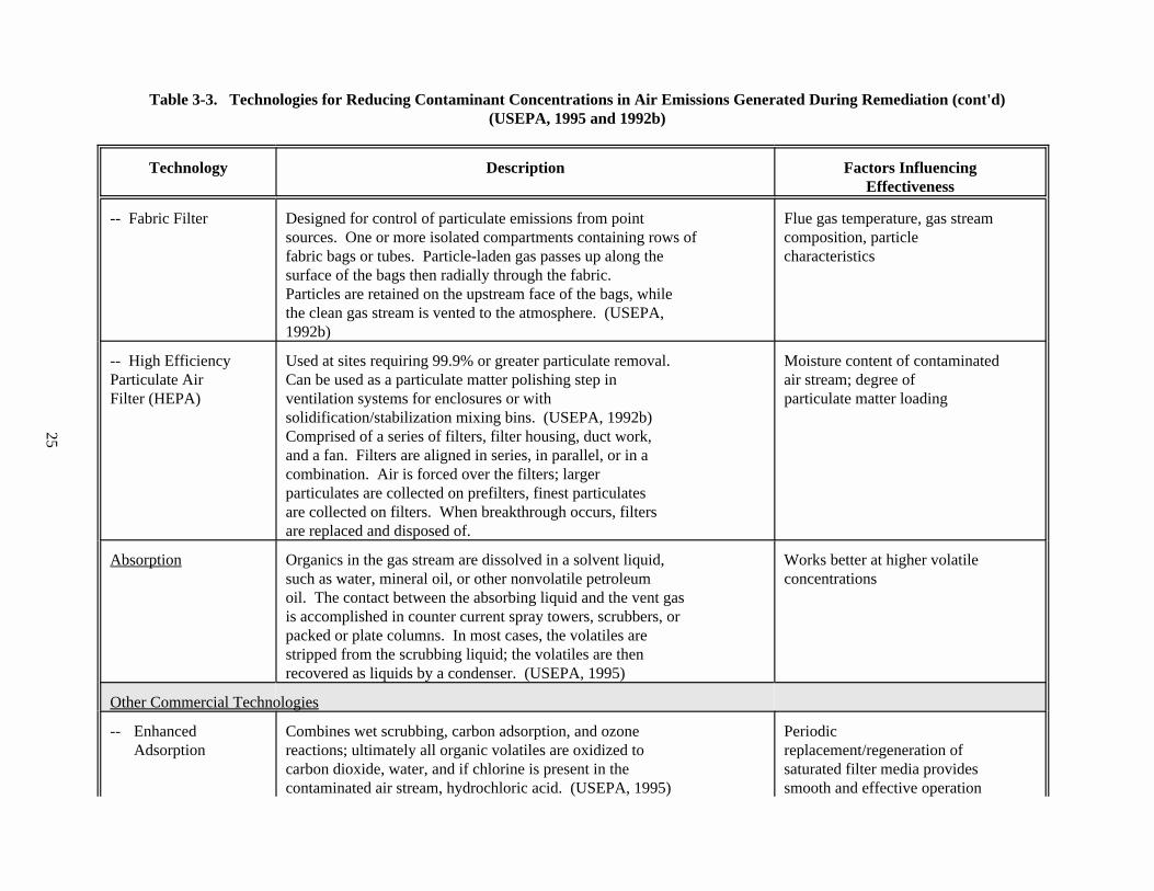
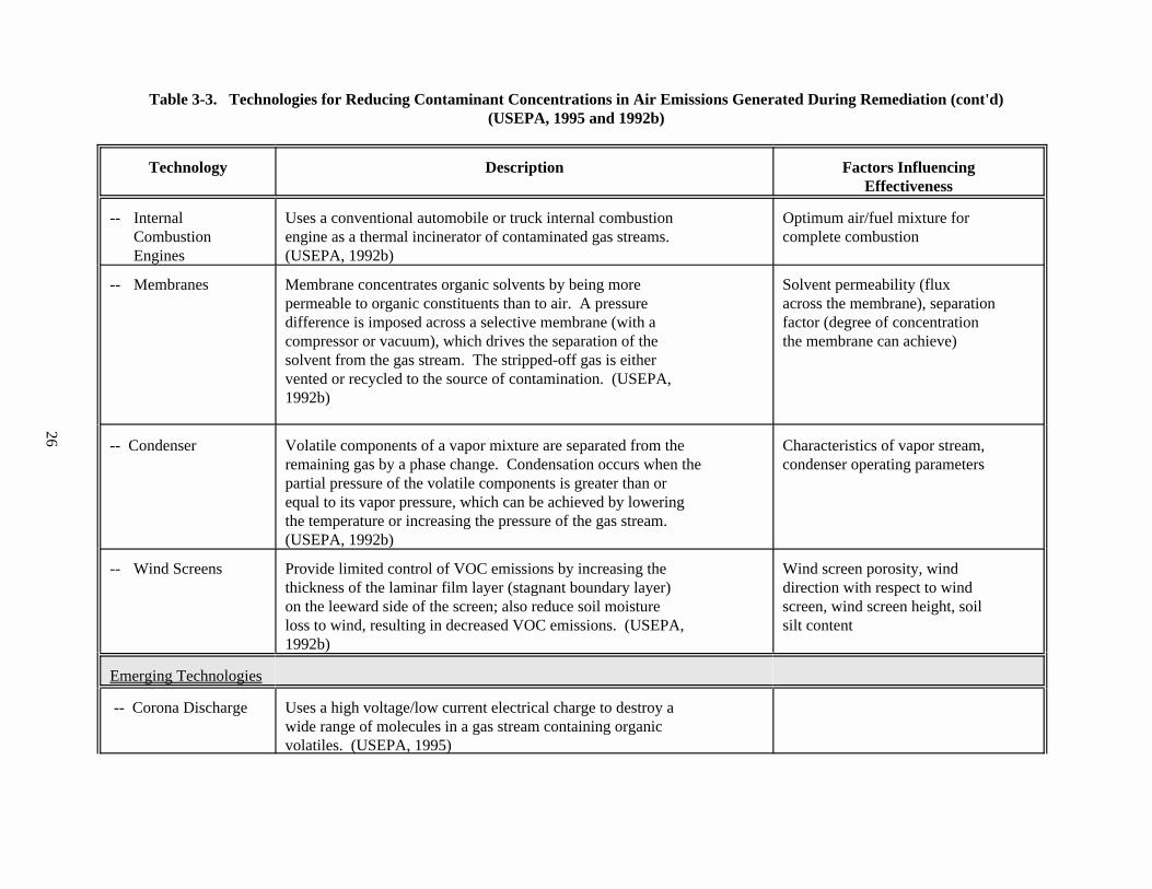
Materials Handling Activities . . . . . . . . . . . . . . . . . . . . . . . . . . . . . . . . . . . . . . . . . . . . 18Table 3-3. Technologies for Reducing Contaminant Concentrations in Air
Emissions Generated During Remediation. . . . . . . . . . . . . . . . . . . . . . . . . . . . . . . . . . 21Table 3-4. Examples of Technologies for Controlling Cross-Media Transfer to Water. . . . . . . . . 24Table 3-5. Examples of Field Monitoring Technologies. . . . . . . . . . . . . . . . . . . . . . . . . . . . . . . . . 26Table 11-1. Key Characteristics of BMP Case Study Sites. . . . . . . . . . . . . . . . . . . . . . . . . . . . . . . 107Table 11-2. Examples of Field/Case Study Findings and Relevant
Modifications of the BMP Guidance Document. . . . . . . . . . . . . . . . . . . . . . . . . . . . . 134
vi
LIST OF FIGURES
Figure 3-1. Relative Cost Effectiveness for Point Source VOC Controls. . . . . . . . . . . . . . . . . 29Figure 4-1. Cross-Sectional View Showing Implementation of Slurry Walls. . . . . . . . . . . . . . 32Figure 4-2. Cross-Section of Multilayer Landfill Cover. . . . . . . . . . . . . . . . . . . . . . . . . . . . . . 32Figure 5-1. Basic Soil Washing Flow Diagram. . . . . . . . . . . . . . . . . . . . . . . . . . . . . . . . . . . . . 39Figure 6-1. Schematic of a Thermal Desorption Treatment System. . . . . . . . . . . . . . . . . . . . . 48Figure 7-1. Schematic of a Soil Vapor Extraction System. . . . . . . . . . . . . . . . . . . . . . . . . . . . . 55Figure 8-1. Schematic for Solid Phase Bioremediation. . . . . . . . . . . . . . . . . . . . . . . . . . . . . . . 63Figure 8-2. Diagram of Solid Phase Biological Treatment Using a Composting Pile. . . . . . . . 66Figure 9-1. Schematic Diagram of a Typical Incineration Facility. . . . . . . . . . . . . . . . . . . . . . 73Figure 9-2. Typical Liquid Injection Incinerator. . . . . . . . . . . . . . . . . . . . . . . . . . . . . . . . . . . . 74Figure 9-3. Typical Fixed/Sloped Hearth Incinerator. . . . . . . . . . . . . . . . . . . . . . . . . . . . . . . . 75Figure 9-4. Typical Multiple Hearth Incinerator. . . . . . . . . . . . . . . . . . . . . . . . . . . . . . . . . . . . 76Figure 9-5. Typical Rotary Kiln Incinerator. . . . . . . . . . . . . . . . . . . . . . . . . . . . . . . . . . . . . . . . 77Figure 10-1. Schematic Diagram of an In Situ RF Heating System. . . . . . . . . . . . . . . . . . . . . . . 83Figure 10-2. Cross-Section of an In Situ RF Heating System. . . . . . . . . . . . . . . . . . . . . . . . . . . 84Figure 10-3. ISV Equipment System. . . . . . . . . . . . . . . . . . . . . . . . . . . . . . . . . . . . . . . . . . . . . . 88Figure 10-4. A Cut-Away View of a Typical Treatment Cell. . . . . . . . . . . . . . . . . . . . . . . . . . . 89Figure 10-5. Schematic of In Situ Flushing Field Test System. . . . . . . . . . . . . . . . . . . . . . . . . . 93Figure 10-6. Soil Flushing Sprinkler System. . . . . . . . . . . . . . . . . . . . . . . . . . . . . . . . . . . . . . . . 94Figure 10-7. Schematic of Soil Flushing System. . . . . . . . . . . . . . . . . . . . . . . . . . . . . . . . . . . . . 94Figure 10-8. Generic Elements of Typical S/S Processes. . . . . . . . . . . . . . . . . . . . . . . . . . . . . . 97
vii
LIST OF ACRONYMS
AEC Area of Environmental ConcernAPCD Air Pollution Control DistrictASME American Society of Mechanical EngineersASTM American Society of Testing and MaterialsATP Anaerobic Thermal ProcessBACT Best Available Control TechnologyBDAT Best Demonstrated Available TechnologyBOD Biochemical Oxygen Demand BMPs Best Management Practice(s)BPT Best Practicable TechnologyBPCT Best Practicable Control TechnologyCAO Corrective Action OrderCAP Corrective Action PlanCERCLA Comprehensive Environmental Response, Compensation, and Liability Act of
1980CFM Cubic Feet Per MinuteCFR Code of Federal RegulationsCMI Corrective Measure ImplementationCMIPP Corrective Measure Implementation (Program Plan)COD Chemical Oxygen DemandCAMU Corrective Action Management UnitCSFS Contaminated Soil Feed StockpilesCWA Clean Water ActDEP Department of Environmental ProtectionDM Dust MonitorDNAPLDense Non-Aqueous Phase LiquidDNR Department of Natural ResourcesDoD Department of DefenseDOE Department of EnergyEPA U.S. Environmental Protection AgencyFACA Federal Advisory Committee ActFCC Federal Communications CommissionFFA Federal Facility AgreementFID Flame Ionization DetectorFR Federal RegisterGAC Granular Activated CarbonGC/MS Gas Chromatography/Mass SpectrometryGCLs Geosynthetic Clay LinersGPD Gallons Per DayHWIR Hazardous Waste Identification RuleHWMMDHazardous Waste Minimization and Management Division of OSW/EPA IRP Installation Restoration ProgramISM Industrial, Scientific, and MedicalISV In Situ VitrificationLNAPLLight Non-Aqueous Phase LiquidLDR Land Disposal RestrictionsMPCA Minnesota Pollution Control Agency
viii
NIOSH National Institute of Occupational Safety and HealthNPDESNational Pollutant Discharge Elimination System (CWA)NRMRLNational Risk Management Research LaboratoryOD Outside DiameterOERR Office of Emergency and Remedial ResponseOPC Other Physical/Chemical TreatmentORD Office of Research and DevelopmentOSW Office of Solid WasteOSWEROffice of Solid Waste and Emergency ResponseOUST Office of Underground Storage TanksOVA Organic Vapor AnalyzerOW Office of WaterPASP Perimeter Air Sampling ProgramPCE PerchloroethylenePIC Products of Incomplete CombustionPID Photoionization DetectorPM Particulate MatterPOHC Principal Organic Hazardous ConstituentPPB Parts Per BillionPPM Parts Per Million (mg/l)PSPD Permits and State Programs Division of OSW/EPAPVC Polyvinyl ChlorideRA Remedial ActionRD Remedial DesignRCRA Resource Conservation and Recovery ActRF Radio FrequencyRFI RCRA Facility InvestigationRI Remedial InvestigationRI/FS Remedial Investigation/Feasibility StudyRSKERRL Robert S. Kerr Environmental Research LaboratorySARA Superfund Amendments and Reauthorization Act of 1986SDWA Safe Drinking Water ActSHSP Site Health and Safety PlanSITE Superfund Innovative Technology EvaluationSPCC Spill Prevention, Containment, and Countermeasure (CWA)SPLP Synthetic Precipitation Leaching Procedure (EPA Method 1312)S/S Solidification/StabilizationSU Standard UnitSVE Soil Vapor ExtractionSVOC Semi-Volatile Organic CompoundSWDA Solid Waste Disposal ActTCE TrichloroethyleneTCLP Toxicity Characteristic Leaching Procedure (EPA Method 1311)TDU Thermal Desorption UnitTIO Technology Innovation OfficeTPH Total Petroleum HydrocarbonsTRPH Total Recoverable Petroleum HydrocarbonsTSDF Treatment, Storage and Disposal FacilityTSS Total Suspended Solids

ix
TWA Time Weighted AverageUSEPAU.S. Environmental Protection AgencyUST Underground Storage TankUXO Unexploded OrdnanceVOC Volatile Organic CompoundWIPP Waste Isolation Pilot PlantWMD Waste Management Division of OSW/EPAXRF X-Ray Fluorescence
1
1.0 Chapter One: INTRODUCTION
This document provides guidance on how to design and conduct soil remediationactivities at RCRA and other hazardous waste sites so that transfers of contaminants fromcontaminated soil to other media (i.e., clean soil, air, and surface or ground water) areminimized. Its primary purpose is to provide guidance on preventing cross-mediatransfers of contaminants during implementation of soils treatment technologies fortreating contaminated soils or solid media in compliance with applicable state and/orfederal regulations. Releases that may result in transfer of contaminants from the soilor solid media to water, air or other natural media are generally referred to as cross-media transfer.
This document is not meant to direct or guide selection of appropriate treatmenttechnologies. Rather, it is only meant to provide advice on the operational practicesrelating to prevention and control of cross-media contamination (hereafter referred toas "Best Management Practices" or "BMPs") that, based on research and past experience,may be best for the selected technology.
As described below, efforts to develop this document were initiated to supportimplementation of the proposed Hazardous Waste Identification Rule for contaminatedmedia (HWIR-media). However, EPA believes that the guidance contained herein will beuseful in many different situations involving cleanup activities, where partiesimplementing a soil treatment technology want to be attentive to cross-mediacontamination concerns and minimize any adverse impact on the overall environment. Thisdocument does not replace any existing state or federal regulations or guidance.
This document is also expected to assist in reducing worker exposure tocontaminants by identifying the potentials for cross-media transfer and recommendingpossible control mechanisms during implementation of soils treatment technologies. Although it is beyond the scope of this document to address the worker health and safetyissues, the recommended BMPs are expected to passively alleviate many of the workerhealth and safety concerns during soils treatment technology implementation.
The cost of implementing the recommended BMPs are generally subsumed in theoverall treatment technology implementation. No specific incremental cost estimates areavailable at this time for application of the recommended BMPs. However, based upon theinformation gathered from a few case studies, a short synopsis on the relative cost ofimplementing BMPs is provided in Section 3.2 of this document.
1.1 Regulatory Background and Need for BMPs Guidance
The Best Management Practices (BMPs) for Soils Treatment Technologies weredeveloped to provide guidance on how to identify and minimize the potential for causingcross-media contamination during implementation of cleanup technologies forcontaminated soils or solid media. The guidance outlines the specific potential cross-media concerns for specific activities and recommends approaches for preventing cross-media transfer of contaminants.
2
EPA originally began to develop the BMPs guidance in response to concerns that somecleanup activities may unintentionally cause additional contamination through cross-media transfer of contaminants. Stakeholders involved in the development of HWIR-mediaraised these concerns to EPA.
The BMPs guidance was not developed for and should not be used as a compliance guidefor any particular set of cleanup standards, but instead should be used as a referenceduring implementation of those standards. The Agency expects that it will be of use inmany contexts, including Superfund cleanups, RCRA Subtitle C corrective action, USTcorrective action, and state cleanups. If any of the recommendations provided in thisguidance causes a conflict with a state or federal regulation, such conflict isunintentional, and the applicable regulation should be followed.
BMPs are not meant to be used as a selection tool for remedial treatmenttechnologies, rather they should be used during the implementation stage of remedies oncethey are selected. EPA believes that this document will be of unique assistance whereparties implementing a soil treatment technology want to be attentive to cross-mediacontamination concerns.
1.2 Structure of BMPs Guidance
The structure of this guidance document is the result of several rounds of analysisand review of the task at hand and the information developed to accomplish it.
Developing and compiling BMPs for each existing soil treatment technology would bea monumental undertaking. To simplify the effort, the BMP team grouped technologiesbased on common features and similarities in their ability to give rise to cross-mediatransfers of contaminants. This resulted in the following seven technology categories:
& Containment Technologies& Soil Washing& Thermal Treatment& Vapor Extraction& Bioremediation& Incineration& Other Physical/Chemical Treatments
It was recognized by the peer reviewers and BMP team members that implementation ofmany technologies involved common activities. To streamline the document and make iteasier to use, BMPs for common activities were compiled into a single chapter. Similarly,information on technologies used for controlling cross-media transfers of contaminantswere also compiled in one chapter for quick reference and to minimize repetition. Individual chapters on different technology categories are made much more technologyspecific. Other characteristics of initial draft guidance, such as organizing BMPs byremedial stage or phase (e.g., site preparation and staging), were also maintained butimproved upon wherever possible, in accordance with reviewers’ comments.
The remainder of this BMPs guidance is structured into ten chapters as follows:
3
Chapter 2 presents BMPs that are not specific to any particular soils treatmenttechnology. In most cases, these BMPs are applicable across a range of remedialactivities and several or most remediation technologies. As presented, these BMPsaddress specific cross-media transfer concerns (e.g., fugitive dust emissions,surface and ground water contamination by runoff), providing information onoperational activities that can reduce the likelihood of transfers duringremediation activities. The information in this chapter is organized relative tovarious remedial stages: site preparation and staging, pre-treatment, and post-treatment/residuals management. Technology-specific BMPs are provided later inChapters 4 through 10.
Chapter 3 provides information on control technologies that can be used inconjunction with BMPs to reduce the likelihood of cross-media contaminationduring soil remediation activities. The information in this chapter is organizedin a series of five tables.
Chapters 4 through 10, respectively, present technology-specific BMPs for each ofthe seven technology categories and, in some cases, for specific technologieswithin those categories. References to Chapters 2 and 3 are provided whereverapplicable. More specifically, each chapter provides the following information:
& Definition and Scope. For each technology category, the guidance providesa definition of the technology and describes the purpose and applicationsof the technologies in each category. A description of the key featurescommon to all the technologies within the category is also provided. When anew technology is introduced that is not specifically addressed in thisguidance, it could be matched with an existing technology category withwhich it shares similar key features, and the appropriate BMPs can beapplied.
& Cross-Media Transfer Potential. The types of potential releases (e.g.,fugitive dust emissions, volatile organic compound (VOC) emissions,leaching of contaminants to ground water) that are of concern for thegeneral technology category and, if they differ, for specific technologieswithin the category are identified. Types of potential releases are tied tothe remedial stage during which they are most likely to occur.
& The Best Management Options to Avoid Potential Cross-Media Transfers. Forthe four major stages of the remediation process, this guidance discussesthose management options or practices, also called BMPs, that are generallyconsidered best to minimize cross-media transfer of contamination. Forexample, the BMPs provided here address techniques that can be used tosuppress fugitive dusts, gas emissions, and odors; minimize surface andground water contamination; limit the effects of human and animal accessacross sites; and other methods that can help to avoid potential cross-media transfers during all activities associated with site remediation. Most of the BMPs in many chapters address activities within the treatmentstage of remediation because those tend to be the most technology specific.
4
Where appropriate, however, BMPs for technology-specific activities thatoccur in other stages are also offered.
& Waste Characteristics that May Increase the Likelihood of Cross-MediaContamination for this Technology. An overview is provided of siteconditions and waste characteristics that might result in a greaterlikelihood of cross-media transfer of contaminants when a technology isapplied in less than optimal site conditions or to treat contaminants forwhich its effectiveness may be limited.
& Residuals Management. Common post-treatment and residual managementissues have been addressed in Chapter 2 of this guidance, which identifiesthe types of residuals that might be generated by the implementation oftechnologies within particular categories and discusses the optionsavailable for the management of residuals to prevent cross-mediacontamination. This guidance only addresses those residuals that have somepotential for cross-media transfer of contaminants or their by-productscreated during treatment.
Chapter 11 provides case studies as well as information on field validationactivities that EPA undertook at soil remediation sites in the Fall and Winter of1996-1997. Useful information gleaned from these case studies and fieldvalidation activities, such as the field applicability of BMPs and associatedcontrol technologies, has been incorporated into this document as appropriate forthe seven technology categories.
In order to easily identify the recommended BMPs, the 7 bullet has been usedexclusively for the recommended BMPs in this document.
1.3 Examples of BMPs
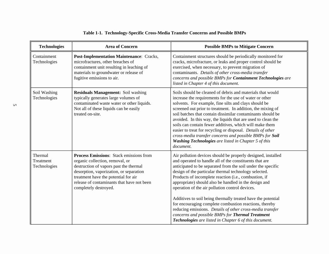
Table 1-1 provides examples of the types of information that can be found in thesechapters. Specifically, this table presents technology-specific cross-media transferconcerns for various technology categories and some of the possible BMPs for addressingthem. This table is not meant to be comprehensive. Many other concerns, and the BMPs thatshould be used to address them, are outlined in the individual technology chapters, andthe reader is encouraged to review all of the information that is pertinent to aparticular technology grouping for best results.
5
Table 1-1. Technology-Specific Cross-Media Transfer Concerns and Possible BMPs
Technologies Area of Concern Possible BMPs to Mitigate Concern
Containment Post-Implementation Maintenance: Cracks, Containment structures should be periodically monitored forTechnologies microfractures, other breaches of cracks, microfracture, or leaks and proper control should be
containment unit resulting in leaching of exercised, when necessary, to prevent migration ofmaterials to groundwater or release of contaminants. Details of other cross-media transferfugitive emissions to air. concerns and possible BMPs for Containment Technologies are
listed in Chapter 4 of this document.
Soil Washing Residuals Management: Soil washing Soils should be cleaned of debris and materials that wouldTechnologies typically generates large volumes of increase the requirements for the use of water or other
contaminated waste water or other liquids. solvents. For example, fine silts and clays should beNot all of these liquids can be easily screened out prior to treatment. In addition, the mixing oftreated on-site. soil batches that contain dissimilar contaminants should be
avoided. In this way, the liquids that are used to clean thesoils can contain fewer additives, which will make themeasier to treat for recycling or disposal. Details of othercross-media transfer concerns and possible BMPs for SoilWashing Technologies are listed in Chapter 5 of thisdocument.
Thermal Process Emissions: Stack emissions from Air pollution devices should be properly designed, installedTreatment organic collection, removal, or and operated to handle all of the constituents that areTechnologies destruction of vapors past the thermal anticipated to be separated from the soil under the specific
desorption, vaporization, or separation design of the particular thermal technology selected. treatment have the potential for air Products of incomplete reaction (i.e., combustion, ifrelease of contaminants that have not been appropriate) should also be handled in the design andcompletely destroyed. operation of the air pollution control devices.
Additives to soil being thermally treated have the potentialfor encouraging complete combustion reactions, therebyreducing emissions. Details of other cross-media transferconcerns and possible BMPs for Thermal TreatmentTechnologies are listed in Chapter 6 of this document.
6
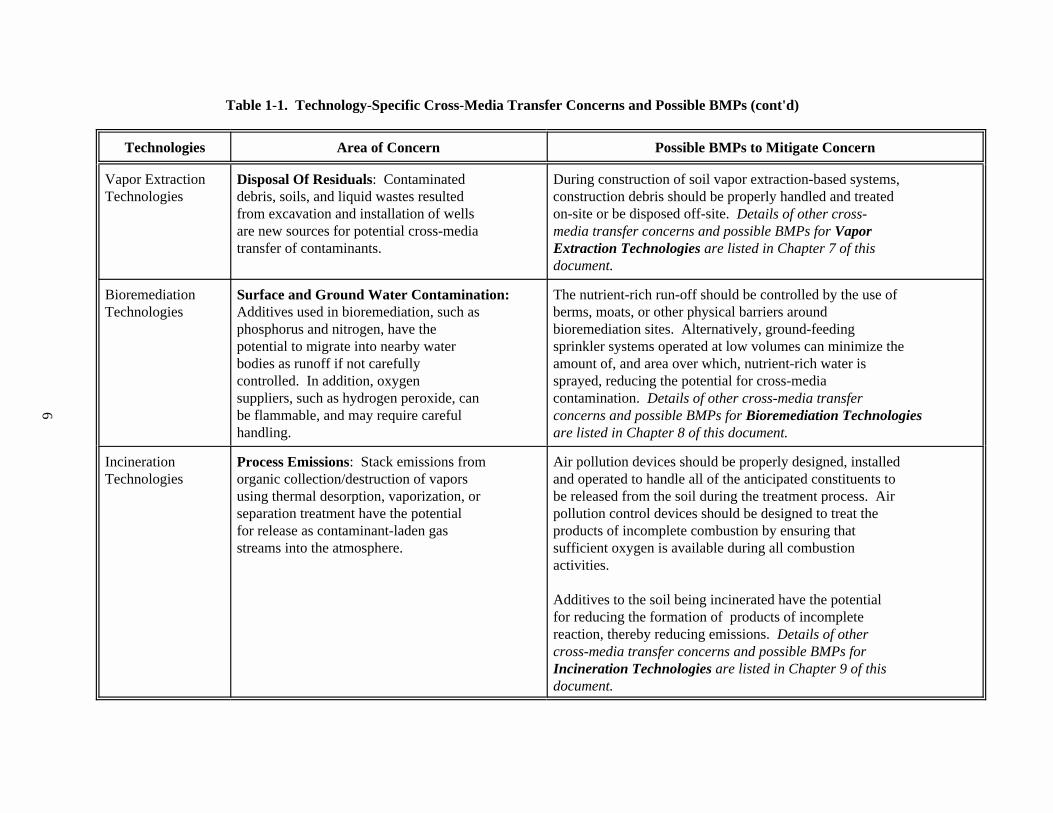
Table 1-1. Technology-Specific Cross-Media Transfer Concerns and Possible BMPs (cont'd)
Technologies Area of Concern Possible BMPs to Mitigate Concern
Vapor Extraction Disposal Of Residuals: Contaminated During construction of soil vapor extraction-based systems,Technologies debris, soils, and liquid wastes resulted construction debris should be properly handled and treated
from excavation and installation of wells on-site or be disposed off-site. Details of other cross-are new sources for potential cross-media media transfer concerns and possible BMPs for Vaportransfer of contaminants. Extraction Technologies are listed in Chapter 7 of this
document.
Bioremediation Surface and Ground Water Contamination: The nutrient-rich run-off should be controlled by the use ofTechnologies Additives used in bioremediation, such as berms, moats, or other physical barriers around
phosphorus and nitrogen, have the bioremediation sites. Alternatively, ground-feedingpotential to migrate into nearby water sprinkler systems operated at low volumes can minimize thebodies as runoff if not carefully amount of, and area over which, nutrient-rich water iscontrolled. In addition, oxygen sprayed, reducing the potential for cross-mediasuppliers, such as hydrogen peroxide, can contamination. Details of other cross-media transferbe flammable, and may require careful concerns and possible BMPs for Bioremediation Technologieshandling. are listed in Chapter 8 of this document.
Incineration Process Emissions: Stack emissions from Air pollution devices should be properly designed, installedTechnologies organic collection/destruction of vapors and operated to handle all of the anticipated constituents to
using thermal desorption, vaporization, or be released from the soil during the treatment process. Airseparation treatment have the potential pollution control devices should be designed to treat thefor release as contaminant-laden gas products of incomplete combustion by ensuring thatstreams into the atmosphere. sufficient oxygen is available during all combustion
activities.
Additives to the soil being incinerated have the potentialfor reducing the formation of products of incompletereaction, thereby reducing emissions. Details of othercross-media transfer concerns and possible BMPs forIncineration Technologies are listed in Chapter 9 of thisdocument.
7
2.0 Chapter Two: GENERAL BMPs for REMEDIATION ACTIVITIES
At many sites with contaminated soil or solid media, remediation activities willbe conducted that have the potential to generate cross-media contamination. Theseactivities generally fall within one of four major remedial stages, regardless of theselected technology (although some technologies may not require or have the same level ofactivity in all stages):
& Site Preparation and Staging& Pre-Treatment& Treatment& Post-Treatment/Residuals Management
These stages are not always discrete and separate from one another. (For example,residuals management is often an issue while treatment is on-going). However, for thepurposes of this document, they are treated individually.
This chapter presents best management practices (BMPs) for addressing thoseremedial activities that are not unique to the technology selected for treatingcontaminated soil or solid media at a site (but that still have the potential to generatecross-media contamination). In other words, these BMPs are likely to have applicabilityto a wide variety of sites because they are associated with a common remedial activity,such as excavation, rather than a specific technology, such as soil washing. The BMPs areorganized according to the remedial stage to which they pertain (e.g., staging and sitepreparation), and then to the applicable cross-media transfer concern (e.g., fugitivedust). The types of remedial activities that may give rise to each concern (e.g.,clearing and grubbing, excavation) are also presented to help in determining theapplicability of BMPs to a particular site.
As reflected in this chapter, BMPs most commonly associated with activitiesperformed as part of site preparation and staging, pretreatment, and post-treatment/residuals management are not technology-specific. BMPs associated withactivities that occur in the treatment stage of a remediation are generally technologyspecific, so they are not addressed here. BMPs for technology-specific activities andcross-media transfer concerns are found in Chapters 4 through 10, which addressindividual technology categories.
2.1 General Cross-Media Transfer Potentials for Various Treatment Technologies
During implementation of any soils treatment technology the following steps aregenerally undertaken: a) Site preparation and staging, b) Pre-treatment activities, c)Treatment activities, and d) Post-treatment activities. Specific cross-media concernsduring the actual treatment activities are addressed separately under the relevanttechnology categories in Chapters 4 through 10. General cross-media transfer potentialfor contaminants mostly during the site preparation, pre-treatment, and post-treatmentactivities are identified below.
& There is risk of inaccurate site characterization with any soils treatmenttechnology operation. The material encountered at the remedial site may
8
not be like the soils studied in treatability or pilot-scale tests. Additional contaminants may be encountered, and the percentage of the fine-grained fraction may be significantly different from that expected. Thesefactors may lead to a long-term storage or generation of high residualvolume, and thus increase the potential for cross-media transfer.
& During several different activities associated with remedyimplementations, including staging and site preparation (e.g., clearing,grubbing); drilling, well installation and trenching operations;mobilization and demobilization of equipment; excavation; transport ofmaterials across the site; and some treatment activities, there is highpotential for fugitive dust emissions due to movement of equipment at thesite. In addition, these same activities can enhance the volatilization ofVOCs, SVOCs, and other potentially hazardous materials into theatmosphere.
& During pretreatment operations such as excavation, storage, sizing,crushing, dewatering, neutralization, blending, and feeding, there is thepotential for dust and VOC emissions from the contaminated media.
& Migration of contaminants to uncontaminated areas may occur duringmobilization or demobilization.
& VOC and SVOC emissions tend to increase during periods of hot and dryweather.
& Leaching of contaminants to surface water can occur from uncoveredstockpiles and excavated pits.
& Improper handling and disposal of residues (e.g., sediment/sludgeresiduals or post-washing wastewater) may allow contaminants to migrateinto and pollute uncontaminated areas.
& Post-treatment discharges of wastewater, if improperly managed, can causemigration of contaminants.
Table 2-1 provides a summary of the fractional contributions of various remedialactivities to the generation of volatile contaminant emissions, which is potentially amajor source of cross-media contamination during many remedial activities.
Table 2-1. Fractional Contributions of Various RemedialActivities to Total Volatile Contaminant Emissions
(USEPA, 1991)
Remedial Activity Contaminant Emissions for the Entire SiteFractional Contribution to Total Volatile
Remediation Process

9
Excavation 0.0509Bucket (Loading) 0.0218Truck Filling 0.0905Transport 0.3051Dumping 0.5016Incineration 0.0014Exposed Soil 0.0287
Total 1.0000
10
2.2 General Best Management Practices for Soils Treatment Technologies
Various control practices to prevent potential cross-media transfer ofcontaminants during cleanup activities have been identified in Tables 3-1 to 3-5. Also,proper system design is recommended prior to implementation of the remedial treatment toavoid cross-media transfer problems during different treatment steps. However, generalBMP options to control specific cross-media transfer of contaminants for differenttreatment technologies are furnished below:
2.2.1 Site Preparation and Staging
Prior to movement of equipment on site the following activities are most commonlyundertaken:
® Site inspections; surveying; boundary staking; drilling and trenching;sampling; demarcation of hot spots; and construction of access roads,utility connections, and fencing.
Special attention and care should be taken during site preparation activities sothat the contaminated media are not disturbed. In case of unavoidable circumstances, thecontaminated media should be subjected to a very minimal disturbance/alteration duringthese activities. The following BMPs are generally recommended:
7 Avoid entering the contaminated area. In unavoidable circumstances, builda temporary decontamination area, which could be later used during cleanupactivities. Any above-ground and underground source of contaminants shouldbe identified and located prior to starting any treatment of contaminatedmedia.
7 Any soils and soil-gas sampling, field air permeability testing,demarcation of hot spot etc. activities should generally be followed byplugging/covering of any holes or depressions created during theseactivities to prevent intrusion of water. It would also be appropriate toinstall relevant signs at the same time so that repeated entry to the site isnot called for.
7 Contaminated drilling mud from any drilling operations should be collectedin a lined/contained system. This will prevent the contaminants frommixing with the normal surface water runoff from the area and thesurrounding natural watercourse.
7 Contaminated waste generated during site preparation or further sitecharacterization activities should be managed protectively as specified inChapter 3, Tables 3-1 to 3-4.
7 Site investigation and operational plans should take into account thepresence of permeable zones and account for potential pre-existingunderground sewers and electrical conduits.
11
7 Surface drainage and subsurface utility systems should be identified.
7 Local watershed management goals and priorities should be incorporatedinto the surface water management plan for the cleanup activities.
2.2.2 Pre-Treatment Activities
Prior to beginning the actual treatment process the following activities are mostcommonly undertaken:
® Excavation, transportation, storage, sizing, crushing, dewatering,neutralization, blending, installation of feeding systems forcontaminated media etc.
During the above activities, measures should be taken to control fugitive dustemissions and to prevent releases of contaminated media to the natural environment. Toprevent cross-media transfer of contaminants, the following BMPs are generallyrecommended for the above activities:
7 Any aboveground and underground sources of contaminants, such as storagetanks, should generally be removed.
7 Any offsite runoff should be prevented from entering and mixing with on-site contaminated media by building earthen berms or adopting similar othermeasures, as outlined in Table 3-4.
7 Provisions should generally be made to capture on-site surface water runoffby diverting it to a controlled depression-area or lined pit.
7 Sizing, crushing, and blending activities should be conducted under anenvironment where the off gases, volatiles, dusts, etc. are all capturedinside a hood or cover, or controlled using other options listed in Chapter3. The dust and VOC emissions associated with these activities that exceedacceptable regulatory limits should be controlled by capturing theseemissions and then treating the captured vapor/air to the extentpracticable. Measures for preventing, collecting and treating dust and VOCemissions are provided in Tables 3-1 and 3-3.
7 When mixing or dewatering, the contaminated aqueous stream should becollected in a lined/contained system. This will prevent the contaminantsfrom mixing with the normal surface water runoff from the area and thesurrounding natural watercourse.
7 Protective management/disposal of contaminated debris is recommended toprevent cross-media transfer. Protective management includes debriswashing, providing covers, testing, and appropriate disposal (see Section11.6.2 (d) and (i)).
12
7 When treating explosive wastes, proper safety and care should be exercisedto prevent any explosion during the treatment process. For conducting safeoperations, recommendations provided in the Handbook (USEPA, 1993) may beused, when necessary.
7 The technology design should be checked to ensure that the corrosion factorhas been taken into account in the design for all appropriate pipes, valves,fittings, tanks, and feed systems.
7 Entry to the active site should be limited to avoid unnecessary exposure andrelated transfer of contaminants.
7 The temporary decontamination area described in Section 2.2.1 should beused as recommended earlier to keep the site-related contaminants withinthe active cleanup area.
7 Fugitive dust emissions should be controlled during excavation by sprayingwater to keep the ground moist. During wet weather or rainfall no waterspraying would be needed.
7 Consideration of climatological extremes/high wind, etc. should be takeninto account when conducting any of the treatment or associated activities. Real-time weather data could be used to monitor weather conditions andaccordingly control treatment operations. During a recent field visit anonsite weather station was observed. The weather monitoring stations werereported to have nominal cost and were found to be highly useful incontrolling weather-related cross-media transfers. To determine possibleextreme conditions, local weather data for the past 10 years could bereviewed from publications (NOAA, 1995) of the National Climatic DataCenter, 151 Patton Avenue, Asheville, NC 28801-5001, Phone: (704) 271-4800.
7 During excavation, blending, and feeding of contaminated soils, VOCemissions should be monitored and appropriate emission control measuresundertaken.
7 Operational plans should include adequate inspection procedures that lookspecifically for corrosion and wear.
7 It is also critical to check that the air pollution control devices aredesigned for the corrosive nature of the hot gases that are expected toenter these devices, when used in certain soil treatment technologies.
7 As an effective erosion control practice, scheduling of constructionactivities should be arranged to limit the time of exposure of disturbedsegments of the site. This entails directing work to one area of a site,then completing and stabilizing that area before moving on to other areas ofthe site.
13
2.2.3 Treatment Activities
Treatment activities and relevant BMPs are specifically described for eachtechnology category in Chapters 4 through 10.
2.2.4 Post-Treatment Activities/Residuals Management
During the post-treatment process the following activities are most commonlyundertaken:
(a) Vapor (Gas) Phase
& Collection or destruction of organics& Collection of particulates& Removal of acid gases
14
(b) Solid and Liquid Phases
& Treatment or disposal of aqueous wastes& Disposal of dusts collected as a result of emission control during
materials handling, stabilization, or any other tertiary/post-treatment
During the conduct of the above activities, measures should be taken to preventrelease of contaminated media to the natural environment. The following BMPs aregenerally recommended for the above activities:
7 Remedial plans should be checked to ensure that they account for theanticipated differences in characteristics of the treated soil. This mayinvolve recombination of the treated soil with uncontaminated soil from thesite (or off-site) in order to approximate the original soilcharacteristics prior to contamination. The anticipated soilcharacteristics of the treated soil should be verified prior toreplacement.
7 Treated wastes should be checked for leachability prior to disposal in alandfill or other similar systems. Possibilities of long-term degradationand migration of contaminants to groundwater should be carefully evaluatedand checked prior to disposal of stabilized/treated material.
7 Contaminated debris, soils, and liquid wastes resulting from excavationand installation of wells should be properly handled, either treated on-site or trucked away for off-site disposal. Berms should be built aroundthe active excavation, storage and treatment areas, if necessary, toprevent migration of contaminated runoff away from the area.
7 If solid materials such as granulated carbon filters are used to collectemissions, they should be removed carefully from the emissions system toavoid rupturing them and dissipating the contaminated carbon materials. They should be placed into tightly covered containers until they can berecycled or properly disposed of.
7 Carbon beds used for VOC removal from the extracted vapor should be properlymanaged and disposed of in compliance with Subtitle C regulations, andshould meet all applicable land disposal standards. If the carbon isregenerated using steam or other means, the residual contaminated, liquidsshould be managed as hazardous wastes, and treated or disposed of incompliance with the applicable regulations.
7 Containers that hold residual liquids should be stored where they cannot bedisturbed or ruptured by large equipment. This may require construction ofa residuals management unit separate from the treatment and storage areas.
15
7 All dusts or other particulates that are collected during emissions controlactivities should be tested for contamination levels and handled anddisposed of properly.
7 Air stripping or other treatment of extracted (contaminated) water/liquidsshould meet all applicable surface water discharge standards for post-treated water.
7 When residual treatment wastes are obtained in the form of pure listedwaste/liquids (e.g., condensate from steam regeneration of carbon beds),the recycling/reuse option for such residual waste should be considered.
2.3 References
1. National Oceanographic and Atmospheric Administration (NOAA). 1995. ComparativeClimatic Data for the United States through 1994, U.S. Department of Commerce,Asheville, NC, October.
2. USEPA. 1993. Approaches for the Remediation of Federal Facility SitesContaminated with Explosive or Radioactive Wastes, EPA/625/R-93/013, Office ofResearch and Development, Washington, DC, September.
3. USEPA. 1991. Engineering Bulletin, Control of Air Emissions from MaterialsHandling During Remediation, EPA/540/2-91/023, Office of Research andDevelopment, October.
16
3.0 Chapter Three: CROSS-MEDIA TRANSFER CONTROL TECHNOLOGIES andMONITORING
This chapter provides descriptions of some of the technologies and practices thatare available to control or treat releases that might create cross-media contaminationduring implementation of treatment technologies for soils and/or solid media. Thesecontrol technologies should generally be applied under the following conditions:
& When potential for cross-media transfer exists associated with the use of asoil treatment technology as identified in Chapters 4 through 10 of thisdocument.
& When recommended in the general best management practices (BMPs) section(Chapter 2) or technology-specific BMPs (Chapters 4 through 10).
& When a safe exposure level for workers is exceeded during cleanupactivities, as determined by the Occupational Safety and HealthAdministration (OSHA), per 29 CFR part 1910.
& Any other site-specific reasons that warrant their application, such asproximity of a populated area or a drinking water source to the site.
3.1 Available Control Technologies
Information contained in this chapter is mostly provided in the following fivetables:
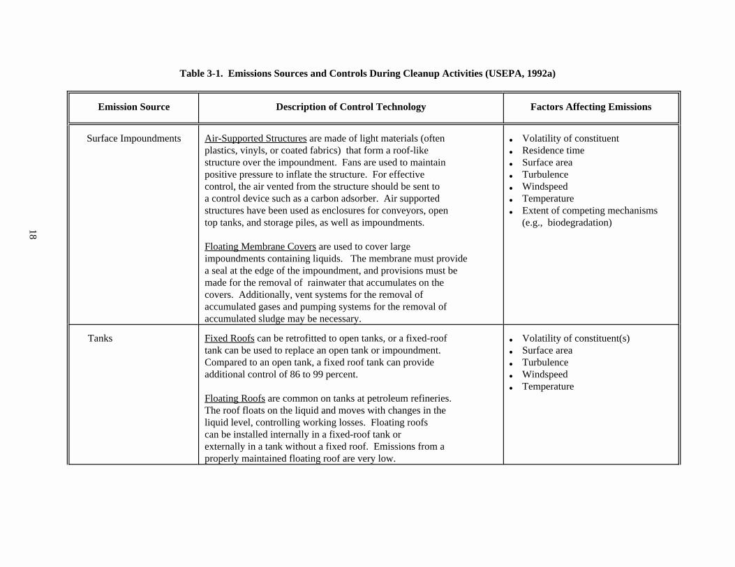
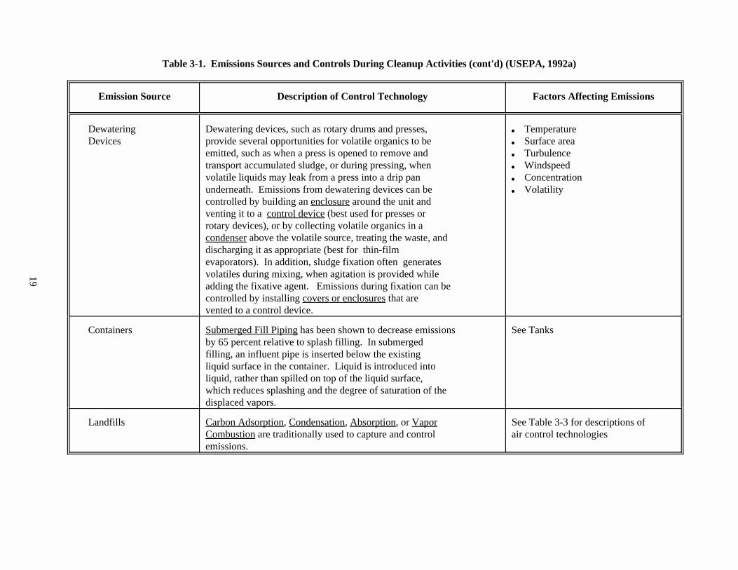
Table 3-1. Emissions Sources and Controls During Cleanup Activities. Thistable lists potential emissions sources that may be encounteredduring cleanup activities such as containers, tanks, and landfills. It describes some common controls that can be used to reduce thoseemissions, and outlines factors that may contribute to thelikelihood of emissions from those sources.
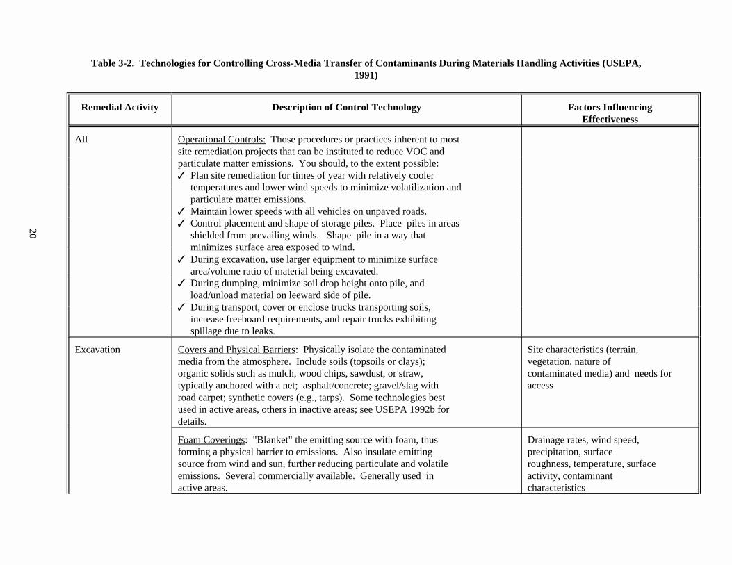
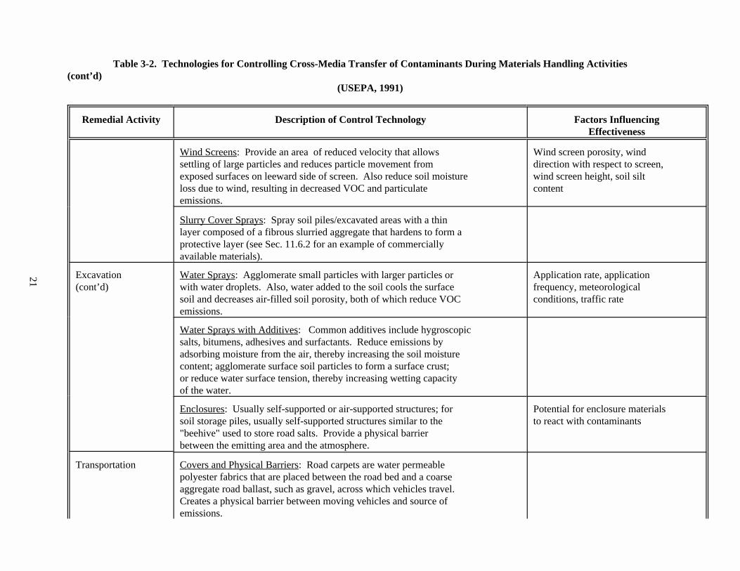
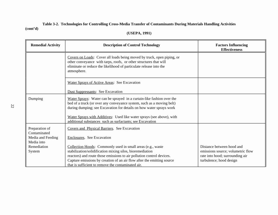
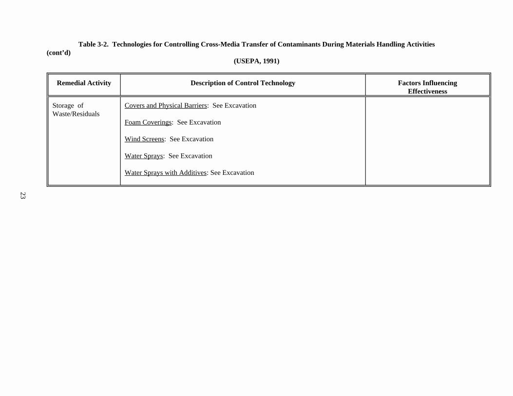
Table 3-2. Technologies for Controlling Cross-Media Transfer of ContaminantsDuring Materials Handling Activities . This table lists materialshandling activities that may be performed during site preparationand staging, as well as pre- and post-treatment, that have thepotential to create cross-media contamination. It provides controltechnologies that can be used during those activities, and listsfactors that may influence the effectiveness of those controltechnologies. Some of the controls listed in this table may beapplicable to treatment activities which are discussed in theindividual remediation technology chapters.
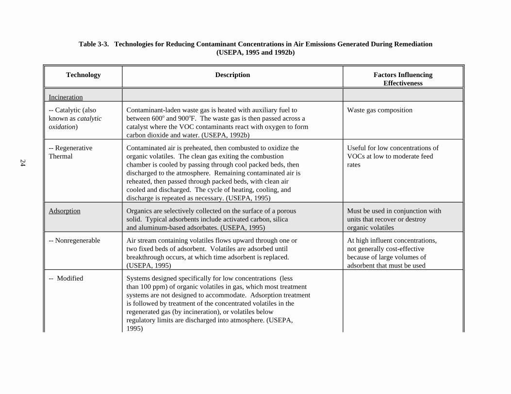
Table 3-3. Technologies for Reducing Contaminant Concentrations in AirEmissions Generated During Remediation. This table provides a listof control technologies that can be used to reduce theconcentrations of air emissions. It describes each technology, and
17
outlines factors that may influence the effectiveness of thosecontrol technologies.
Table 3-4. Examples of Technologies for Controlling Cross-Media Transfer toWater. This table provides a list of controls that should beconsidered during all remedial activities to minimize the potentialfor releases from soil to surface and/or ground water. The examplesprovided are for relatively small-scale structures that can beapplied to short-term projects; for larger-scale and long-termprojects, consult the Metropolitan Washington Council ofGovernments document cited in the references.
Table 3-5. Examples of Field Monitoring Technologies. This table provides alist of technologies or practices that can be used to monitorpotential emissions during remediation activities. It describesthe technologies that can be used to monitor emissions from activeand inactive sites. These technologies can be applied prior to andduring remediation, as needed. A few simple and easy-to-usemonitoring techniques are also listed in this table.
18
Table 3-1. Emissions Sources and Controls During Cleanup Activities (USEPA, 1992a)
Emission Source Description of Control Technology Factors Affecting Emissions
Surface Impoundments Air-Supported Structures are made of light materials (often & Volatility of constituentplastics, vinyls, or coated fabrics) that form a roof-like & Residence timestructure over the impoundment. Fans are used to maintain & Surface areapositive pressure to inflate the structure. For effective & Turbulencecontrol, the air vented from the structure should be sent to & Windspeeda control device such as a carbon adsorber. Air supported & Temperaturestructures have been used as enclosures for conveyors, open & Extent of competing mechanismstop tanks, and storage piles, as well as impoundments. (e.g., biodegradation)
Floating Membrane Covers are used to cover largeimpoundments containing liquids. The membrane must providea seal at the edge of the impoundment, and provisions must bemade for the removal of rainwater that accumulates on thecovers. Additionally, vent systems for the removal ofaccumulated gases and pumping systems for the removal ofaccumulated sludge may be necessary.
Tanks Fixed Roofs can be retrofitted to open tanks, or a fixed-roof & Volatility of constituent(s)tank can be used to replace an open tank or impoundment. & Surface areaCompared to an open tank, a fixed roof tank can provide & Turbulenceadditional control of 86 to 99 percent. & Windspeed
Floating Roofs are common on tanks at petroleum refineries. The roof floats on the liquid and moves with changes in theliquid level, controlling working losses. Floating roofscan be installed internally in a fixed-roof tank orexternally in a tank without a fixed roof. Emissions from aproperly maintained floating roof are very low.
& Temperature
19
Table 3-1. Emissions Sources and Controls During Cleanup Activities (cont'd) (USEPA, 1992a)
Emission Source Description of Control Technology Factors Affecting Emissions
Dewatering Dewatering devices, such as rotary drums and presses, & TemperatureDevices provide several opportunities for volatile organics to be & Surface area
emitted, such as when a press is opened to remove and & Turbulencetransport accumulated sludge, or during pressing, when & Windspeedvolatile liquids may leak from a press into a drip pan & Concentrationunderneath. Emissions from dewatering devices can be & Volatilitycontrolled by building an enclosure around the unit andventing it to a control device (best used for presses orrotary devices), or by collecting volatile organics in acondenser above the volatile source, treating the waste, anddischarging it as appropriate (best for thin-filmevaporators). In addition, sludge fixation often generatesvolatiles during mixing, when agitation is provided whileadding the fixative agent. Emissions during fixation can becontrolled by installing covers or enclosures that arevented to a control device.
Containers Submerged Fill Piping has been shown to decrease emissions See Tanksby 65 percent relative to splash filling. In submergedfilling, an influent pipe is inserted below the existingliquid surface in the container. Liquid is introduced intoliquid, rather than spilled on top of the liquid surface,which reduces splashing and the degree of saturation of thedisplaced vapors.
Landfills Carbon Adsorption, Condensation, Absorption, or Vapor See Table 3-3 for descriptions of Combustion are traditionally used to capture and control air control technologiesemissions.
20
Table 3-2. Technologies for Controlling Cross-Media Transfer of Contaminants During Materials Handling Activities (USEPA,1991)
Remedial Activity Description of Control Technology Factors InfluencingEffectiveness
All Operational Controls: Those procedures or practices inherent to mostsite remediation projects that can be instituted to reduce VOC andparticulate matter emissions. You should, to the extent possible:7 Plan site remediation for times of year with relatively cooler
temperatures and lower wind speeds to minimize volatilization andparticulate matter emissions.
7 Maintain lower speeds with all vehicles on unpaved roads.7 Control placement and shape of storage piles. Place piles in areas
shielded from prevailing winds. Shape pile in a way thatminimizes surface area exposed to wind.
7 During excavation, use larger equipment to minimize surfacearea/volume ratio of material being excavated.
7 During dumping, minimize soil drop height onto pile, andload/unload material on leeward side of pile.
7 During transport, cover or enclose trucks transporting soils,increase freeboard requirements, and repair trucks exhibitingspillage due to leaks.
Excavation Covers and Physical Barriers: Physically isolate the contaminated Site characteristics (terrain,media from the atmosphere. Include soils (topsoils or clays); vegetation, nature oforganic solids such as mulch, wood chips, sawdust, or straw, contaminated media) and needs fortypically anchored with a net; asphalt/concrete; gravel/slag with accessroad carpet; synthetic covers (e.g., tarps). Some technologies bestused in active areas, others in inactive areas; see USEPA 1992b fordetails.
Foam Coverings: "Blanket" the emitting source with foam, thus Drainage rates, wind speed,forming a physical barrier to emissions. Also insulate emitting precipitation, surfacesource from wind and sun, further reducing particulate and volatile roughness, temperature, surfaceemissions. Several commercially available. Generally used in activity, contaminantactive areas. characteristics
21
Table 3-2. Technologies for Controlling Cross-Media Transfer of Contaminants During Materials Handling Activities(cont’d)
(USEPA, 1991)
Remedial Activity Description of Control Technology Factors InfluencingEffectiveness
Wind Screens: Provide an area of reduced velocity that allows Wind screen porosity, windsettling of large particles and reduces particle movement from direction with respect to screen,exposed surfaces on leeward side of screen. Also reduce soil moisture wind screen height, soil siltloss due to wind, resulting in decreased VOC and particulate contentemissions.
Slurry Cover Sprays: Spray soil piles/excavated areas with a thinlayer composed of a fibrous slurried aggregate that hardens to form aprotective layer (see Sec. 11.6.2 for an example of commerciallyavailable materials).
Excavation Water Sprays: Agglomerate small particles with larger particles or Application rate, application(cont’d) with water droplets. Also, water added to the soil cools the surface frequency, meteorological
soil and decreases air-filled soil porosity, both of which reduce VOC conditions, traffic rateemissions.
Water Sprays with Additives: Common additives include hygroscopicsalts, bitumens, adhesives and surfactants. Reduce emissions byadsorbing moisture from the air, thereby increasing the soil moisturecontent; agglomerate surface soil particles to form a surface crust;or reduce water surface tension, thereby increasing wetting capacityof the water.
Enclosures: Usually self-supported or air-supported structures; for Potential for enclosure materialssoil storage piles, usually self-supported structures similar to the to react with contaminants"beehive" used to store road salts. Provide a physical barrierbetween the emitting area and the atmosphere.
Transportation Covers and Physical Barriers: Road carpets are water permeablepolyester fabrics that are placed between the road bed and a coarseaggregate road ballast, such as gravel, across which vehicles travel. Creates a physical barrier between moving vehicles and source ofemissions.
22
Table 3-2. Technologies for Controlling Cross-Media Transfer of Contaminants During Materials Handling Activities(cont’d)
(USEPA, 1991)
Remedial Activity Description of Control Technology Factors InfluencingEffectiveness
Covers on Loads: Cover all loads being moved by truck, open piping, orother conveyance with tarps, roofs, or other structures that willeliminate or reduce the likelihood of particulate release into theatmosphere.
Water Sprays of Active Areas: See Excavation
Dust Suppressants: See Excavation
Dumping Water Sprays: Water can be sprayed in a curtain-like fashion over thebed of a truck (or over any conveyance system, such as a moving belt)during dumping; see Excavation for details on how water sprays work
Water Sprays with Additives: Used like water sprays (see above), withadditional substances such as surfactants; see Excavation
Preparation of Covers and Physical Barriers. See ExcavationContaminatedMedia and Feeding Enclosures. See ExcavationMedia intoRemediation Collection Hoods: Commonly used in small areas (e.g., waste Distance between hood andSystem stabilization/solidification mixing silos, bioremediation emissions source; volumetric flow
reactors) and route those emissions to air pollution control devices. rate into hood; surrounding airCapture emissions by creation of an air flow after the emitting source turbulence; hood designthat is sufficient to remove the contaminated air.
23
Table 3-2. Technologies for Controlling Cross-Media Transfer of Contaminants During Materials Handling Activities(cont’d)
(USEPA, 1991)
Remedial Activity Description of Control Technology Factors InfluencingEffectiveness
Storage of Covers and Physical Barriers: See ExcavationWaste/Residuals
Foam Coverings: See Excavation
Wind Screens: See Excavation
Water Sprays: See Excavation
Water Sprays with Additives: See Excavation
24
Table 3-3. Technologies for Reducing Contaminant Concentrations in Air Emissions Generated During Remediation(USEPA, 1995 and 1992b)
Technology Description Factors InfluencingEffectiveness
Incineration
-- Catalytic (also Contaminant-laden waste gas is heated with auxiliary fuel to Waste gas compositionknown as catalytic between 600 and 900 F. The waste gas is then passed across aoxidation) catalyst where the VOC contaminants react with oxygen to form
o o
carbon dioxide and water. (USEPA, 1992b)
-- Regenerative Contaminated air is preheated, then combusted to oxidize the Useful for low concentrations ofThermal organic volatiles. The clean gas exiting the combustion VOCs at low to moderate feed
chamber is cooled by passing through cool packed beds, then ratesdischarged to the atmosphere. Remaining contaminated air isreheated, then passed through packed beds, with clean aircooled and discharged. The cycle of heating, cooling, anddischarge is repeated as necessary. (USEPA, 1995)
Adsorption Organics are selectively collected on the surface of a porous Must be used in conjunction withsolid. Typical adsorbents include activated carbon, silica units that recover or destroyand aluminum-based adsorbates. (USEPA, 1995) organic volatiles
-- Nonregenerable Air stream containing volatiles flows upward through one or At high influent concentrations,two fixed beds of adsorbent. Volatiles are adsorbed until not generally cost-effectivebreakthrough occurs, at which time adsorbent is replaced. because of large volumes of(USEPA, 1995) adsorbent that must be used
-- Modified Systems designed specifically for low concentrations (lessthan 100 ppm) of organic volatiles in gas, which most treatmentsystems are not designed to accommodate. Adsorption treatmentis followed by treatment of the concentrated volatiles in theregenerated gas (by incineration), or volatiles belowregulatory limits are discharged into atmosphere. (USEPA,1995)
25
Table 3-3. Technologies for Reducing Contaminant Concentrations in Air Emissions Generated During Remediation (cont'd)(USEPA, 1995 and 1992b)
Technology Description Factors InfluencingEffectiveness
-- Fabric Filter Designed for control of particulate emissions from point Flue gas temperature, gas streamsources. One or more isolated compartments containing rows of composition, particlefabric bags or tubes. Particle-laden gas passes up along the characteristicssurface of the bags then radially through the fabric. Particles are retained on the upstream face of the bags, whilethe clean gas stream is vented to the atmosphere. (USEPA,1992b)
-- High Efficiency Used at sites requiring 99.9% or greater particulate removal. Moisture content of contaminatedParticulate Air Can be used as a particulate matter polishing step in air stream; degree ofFilter (HEPA) ventilation systems for enclosures or with particulate matter loading
solidification/stabilization mixing bins. (USEPA, 1992b) Comprised of a series of filters, filter housing, duct work,and a fan. Filters are aligned in series, in parallel, or in acombination. Air is forced over the filters; largerparticulates are collected on prefilters, finest particulatesare collected on filters. When breakthrough occurs, filtersare replaced and disposed of.
Absorption Organics in the gas stream are dissolved in a solvent liquid, Works better at higher volatilesuch as water, mineral oil, or other nonvolatile petroleum concentrationsoil. The contact between the absorbing liquid and the vent gasis accomplished in counter current spray towers, scrubbers, orpacked or plate columns. In most cases, the volatiles arestripped from the scrubbing liquid; the volatiles are thenrecovered as liquids by a condenser. (USEPA, 1995)
Other Commercial Technologies
-- Enhanced Combines wet scrubbing, carbon adsorption, and ozone PeriodicAdsorption reactions; ultimately all organic volatiles are oxidized to replacement/regeneration of
carbon dioxide, water, and if chlorine is present in the saturated filter media providescontaminated air stream, hydrochloric acid. (USEPA, 1995) smooth and effective operation
26
Table 3-3. Technologies for Reducing Contaminant Concentrations in Air Emissions Generated During Remediation (cont'd)(USEPA, 1995 and 1992b)
Technology Description Factors InfluencingEffectiveness
-- Internal Uses a conventional automobile or truck internal combustion Optimum air/fuel mixture forCombustion engine as a thermal incinerator of contaminated gas streams. complete combustionEngines (USEPA, 1992b)
-- Membranes Membrane concentrates organic solvents by being more Solvent permeability (fluxpermeable to organic constituents than to air. A pressure across the membrane), separationdifference is imposed across a selective membrane (with a factor (degree of concentrationcompressor or vacuum), which drives the separation of the the membrane can achieve)solvent from the gas stream. The stripped-off gas is eithervented or recycled to the source of contamination. (USEPA,1992b)
-- Condenser Volatile components of a vapor mixture are separated from the Characteristics of vapor stream,remaining gas by a phase change. Condensation occurs when the condenser operating parameterspartial pressure of the volatile components is greater than orequal to its vapor pressure, which can be achieved by loweringthe temperature or increasing the pressure of the gas stream. (USEPA, 1992b)
-- Wind Screens Provide limited control of VOC emissions by increasing the Wind screen porosity, windthickness of the laminar film layer (stagnant boundary layer) direction with respect to windon the leeward side of the screen; also reduce soil moisture screen, wind screen height, soilloss to wind, resulting in decreased VOC emissions. (USEPA, silt content1992b)
Emerging Technologies
-- Corona Discharge Uses a high voltage/low current electrical charge to destroy awide range of molecules in a gas stream containing organicvolatiles. (USEPA, 1995)
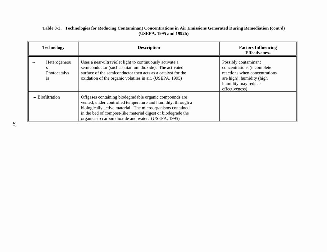
27
Table 3-3. Technologies for Reducing Contaminant Concentrations in Air Emissions Generated During Remediation (cont'd)(USEPA, 1995 and 1992b)
Technology Description Factors InfluencingEffectiveness
-- Heterogeneou Uses a near-ultraviolet light to continuously activate a Possibly contaminants semiconductor (such as titanium dioxide). The activated concentrations (incompletePhotocatalys surface of the semiconductor then acts as a catalyst for the reactions when concentrationsis oxidation of the organic volatiles in air. (USEPA, 1995) are high); humidity (high
humidity may reduceeffectiveness)
-- Biofiltration Offgases containing biodegradable organic compounds arevented, under controlled temperature and humidity, through abiologically active material. The microorganisms containedin the bed of compost-like material digest or biodegrade theorganics to carbon dioxide and water. (USEPA, 1995)
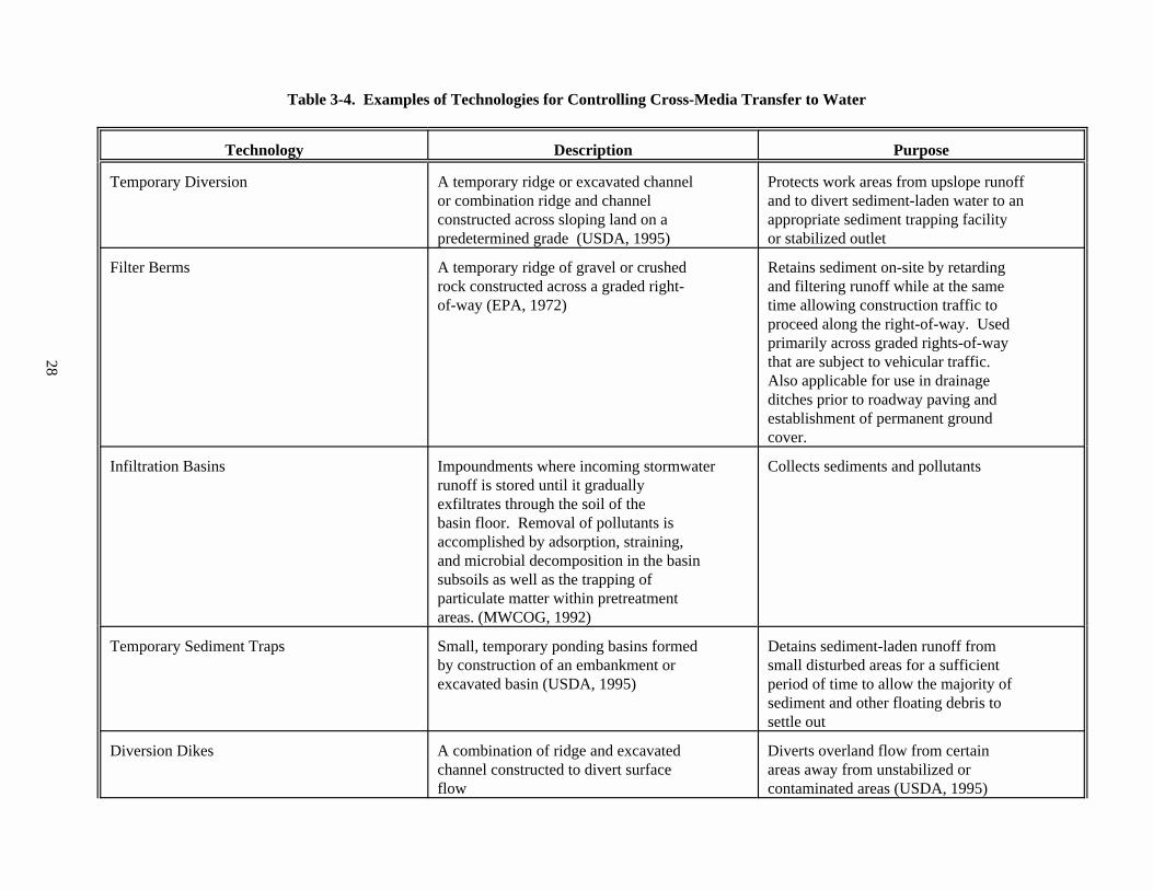
28
Table 3-4. Examples of Technologies for Controlling Cross-Media Transfer to Water
Technology Description Purpose
Temporary Diversion A temporary ridge or excavated channel Protects work areas from upslope runoffor combination ridge and channel and to divert sediment-laden water to anconstructed across sloping land on a appropriate sediment trapping facilitypredetermined grade (USDA, 1995) or stabilized outlet
Filter Berms A temporary ridge of gravel or crushed Retains sediment on-site by retardingrock constructed across a graded right- and filtering runoff while at the sameof-way (EPA, 1972) time allowing construction traffic to
proceed along the right-of-way. Usedprimarily across graded rights-of-waythat are subject to vehicular traffic. Also applicable for use in drainageditches prior to roadway paving andestablishment of permanent groundcover.
Infiltration Basins Impoundments where incoming stormwater Collects sediments and pollutantsrunoff is stored until it graduallyexfiltrates through the soil of thebasin floor. Removal of pollutants isaccomplished by adsorption, straining,and microbial decomposition in the basinsubsoils as well as the trapping ofparticulate matter within pretreatmentareas. (MWCOG, 1992)
Temporary Sediment Traps Small, temporary ponding basins formed Detains sediment-laden runoff fromby construction of an embankment or small disturbed areas for a sufficientexcavated basin (USDA, 1995) period of time to allow the majority of
sediment and other floating debris tosettle out
Diversion Dikes A combination of ridge and excavated Diverts overland flow from certainchannel constructed to divert surface areas away from unstabilized orflow contaminated areas (USDA, 1995)
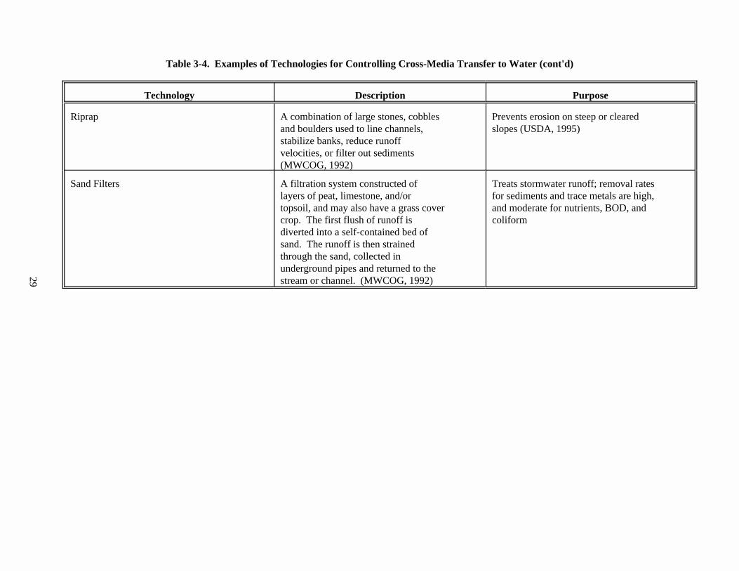
29
Table 3-4. Examples of Technologies for Controlling Cross-Media Transfer to Water (cont'd)
Technology Description Purpose
Riprap A combination of large stones, cobbles Prevents erosion on steep or clearedand boulders used to line channels, slopes (USDA, 1995)stabilize banks, reduce runoffvelocities, or filter out sediments (MWCOG, 1992)
Sand Filters A filtration system constructed of Treats stormwater runoff; removal rateslayers of peat, limestone, and/or for sediments and trace metals are high,topsoil, and may also have a grass cover and moderate for nutrients, BOD, andcrop. The first flush of runoff is coliformdiverted into a self-contained bed ofsand. The runoff is then strainedthrough the sand, collected inunderground pipes and returned to thestream or channel. (MWCOG, 1992)
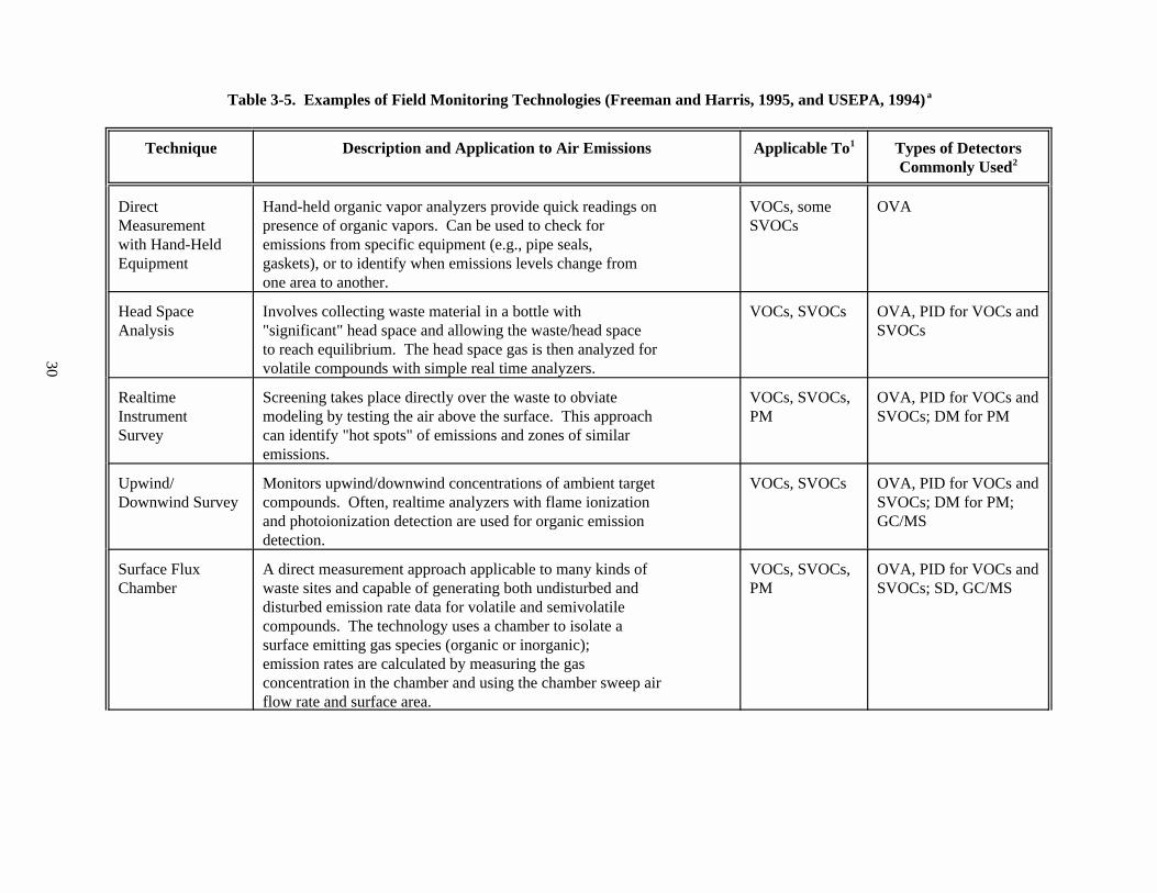
30
Table 3-5. Examples of Field Monitoring Technologies (Freeman and Harris, 1995, and USEPA, 1994)a
Technique Description and Application to Air Emissions Applicable To Types of Detectors1
Commonly Used2
Direct Hand-held organic vapor analyzers provide quick readings on VOCs, some OVAMeasurement presence of organic vapors. Can be used to check for SVOCswith Hand-Held emissions from specific equipment (e.g., pipe seals,Equipment gaskets), or to identify when emissions levels change from
one area to another.
Head Space Involves collecting waste material in a bottle with VOCs, SVOCs OVA, PID for VOCs andAnalysis "significant" head space and allowing the waste/head space SVOCs
to reach equilibrium. The head space gas is then analyzed forvolatile compounds with simple real time analyzers.
Realtime Screening takes place directly over the waste to obviate VOCs, SVOCs, OVA, PID for VOCs andInstrument modeling by testing the air above the surface. This approach PM SVOCs; DM for PMSurvey can identify "hot spots" of emissions and zones of similar
emissions.
Upwind/ Monitors upwind/downwind concentrations of ambient target VOCs, SVOCs OVA, PID for VOCs andDownwind Survey compounds. Often, realtime analyzers with flame ionization SVOCs; DM for PM;
and photoionization detection are used for organic emission GC/MSdetection.
Surface Flux A direct measurement approach applicable to many kinds of VOCs, SVOCs, OVA, PID for VOCs andChamber waste sites and capable of generating both undisturbed and PM SVOCs; SD, GC/MS
disturbed emission rate data for volatile and semivolatilecompounds. The technology uses a chamber to isolate asurface emitting gas species (organic or inorganic);emission rates are calculated by measuring the gasconcentration in the chamber and using the chamber sweep airflow rate and surface area.
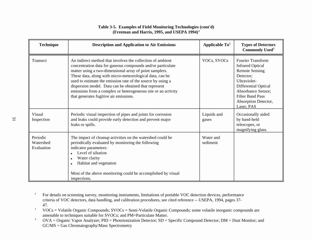
31
Table 3-5. Examples of Field Monitoring Technologies (cont'd)(Freeman and Harris, 1995, and USEPA 1994)a
Technique Description and Application to Air Emissions Applicable To Types of Detectors1
Commonly Used2
Transect An indirect method that involves the collection of ambient VOCs, SVOCs Fourier Transformconcentration data for gaseous compounds and/or particulate Infrared Opticalmatter using a two-dimensional array of point samplers. Remote SensingThese data, along with micro-meteorological data, can be Detector;used to estimate the emission rate of the source by using a Ultraviolet-dispersion model. Data can be obtained that represent Differential Opticalemissions from a complex or heterogeneous site or an activity Absorbance Sensor;that generates fugitive air emissions. Filter Band Pass
Absorption Detector,Laser, PAS
Visual Periodic visual inspection of pipes and joints for corrosion Liquids and Occasionally aidedInspection and leaks could provide early detection and prevent major gases by hand-held
leaks or spills. telescopes, ormagnifying glass.
Periodic The impact of cleanup activities on the watershed could be Water andWatershed periodically evaluated by monitoring the following sedimentEvaluation indicator parameters:
& Level of siltation& Water clarity& Habitat and vegetation
Most of the above monitoring could be accomplished by visualinspections.
For details on screening survey, monitoring instruments, limitations of portable VOC detection devices, performancea
criteria of VOC detectors, data handling, and calibration procedures, see cited reference -- USEPA, 1994, pages 37-47.VOCs = Volatile Organic Compounds; SVOCs = Semi-Volatile Organic Compounds; some volatile inorganic compounds are1
amenable to techniques suitable for SVOCs; and PM=Particulate Matter.OVA = Organic Vapor Analyzer; PID = Photoionization Detector; SD = Specific Compound Detector; DM = Dust Monitor; and2
GC/MS = Gas Chromatography/Mass Spectrometry
32
3.2 Relative Costs of Implementing BMPs
EPA did not conduct an exhaustive analysis of the costs associated withimplementing the practices outlined in this document. Conducting such an analysis iscomplicated by two key factors: (1) many of the suggested practices do not involveequipment purchases nor do they entail a well-defined or discrete task outside theintegral remediation activities, and (2) cost data available on soil cleanups tend to beaggregated such that costs for performing specific practices are not discernable. Inaddition, the practices applicable or necessary for a particular cleanup, and themagnitude to which they are performed, can vary based on the characteristics of the siteand those of the contaminants present.
Notwithstanding, as a general rule, EPA does not expect cleanup managers to incur asignificant incremental cost in implementing the practices suggested in this document. In fact, at many sites, cleanup managers are already implementing the applicablepractices as part of the good management practices they follow whenever performingcleanups. The costs of implementing these practices are subsumed into their overallcleanup costs. EPA recognizes that, in some cases, additional costs may be incurred toimplement cross-media transfer controls. However, in these cases, these costs wouldprobably need to be incurred anyway to meet existing state or federal cleanuprequirements or to avert potential future costs to address cross-media transfers ofcontaminants. Based on preliminary cost data gathered during field validation of BMPs,these costs are generally an integral part of the cost of remedial activity and areestimated to comprise about two to six percent of the overall cleanup cost.
EPA welcomes any data that will help to more fully characterize the costs relatedto minimizing cross-media transfers of contaminants.
Although actual cost figures are not available at this time for the recommendedBMPs, studies have been conducted earlier by EPA on the relative cost effectiveness forpoint source VOC controls as shown in Figure 3-1 (USEPA, 1992b).
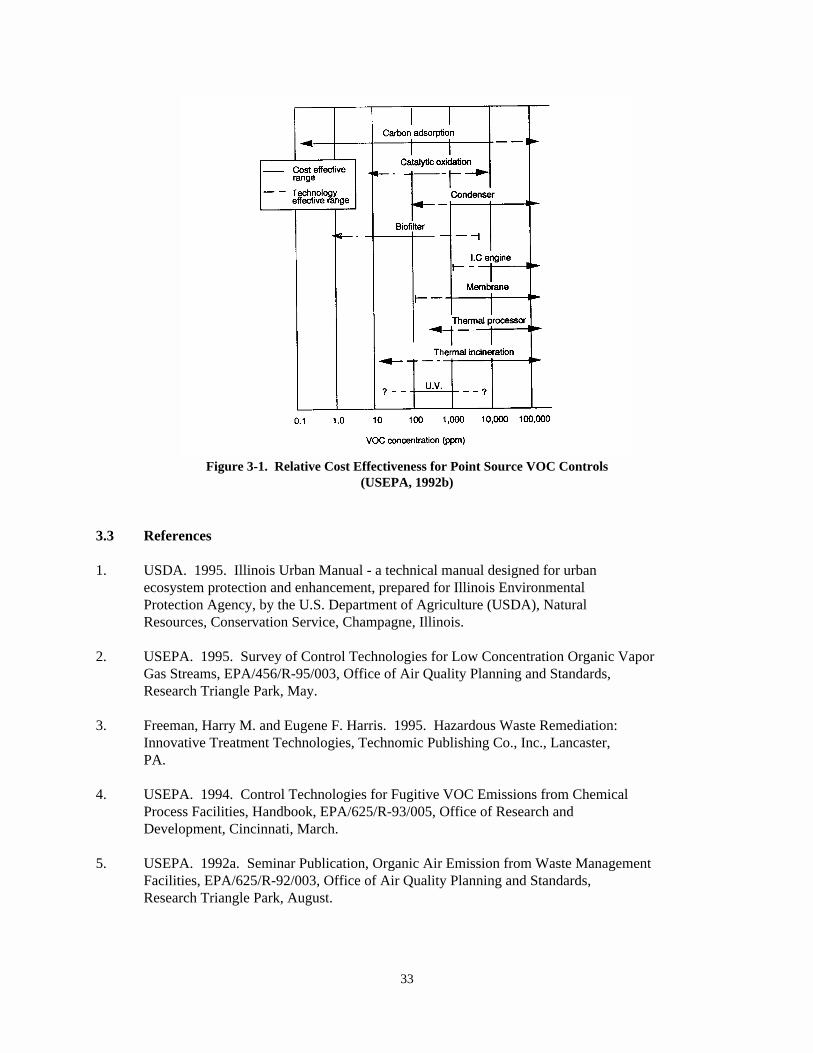
33
Figure 3-1. Relative Cost Effectiveness for Point Source VOC Controls(USEPA, 1992b)
3.3 References
1. USDA. 1995. Illinois Urban Manual - a technical manual designed for urbanecosystem protection and enhancement, prepared for Illinois EnvironmentalProtection Agency, by the U.S. Department of Agriculture (USDA), NaturalResources, Conservation Service, Champagne, Illinois.
2. USEPA. 1995. Survey of Control Technologies for Low Concentration Organic VaporGas Streams, EPA/456/R-95/003, Office of Air Quality Planning and Standards,Research Triangle Park, May.
3. Freeman, Harry M. and Eugene F. Harris. 1995. Hazardous Waste Remediation: Innovative Treatment Technologies, Technomic Publishing Co., Inc., Lancaster,PA.
4. USEPA. 1994. Control Technologies for Fugitive VOC Emissions from ChemicalProcess Facilities, Handbook, EPA/625/R-93/005, Office of Research andDevelopment, Cincinnati, March.
5. USEPA. 1992a. Seminar Publication, Organic Air Emission from Waste ManagementFacilities, EPA/625/R-92/003, Office of Air Quality Planning and Standards,Research Triangle Park, August.
34
6. USEPA. 1992b. Control of Air Emissions from Superfund Sites, EPA/625/R-92/012,Office of Research and Development, November.
7. Metropolitan Washington Council of Government (MWCOG). 1992. A CurrentAssessment of Urban Best Management Practices, a report prepared for U.S. EPA'sOffice of Wetlands, Oceans, and Watersheds, March.
8. USEPA. 1991. Engineering Bulletin, Control of Air Emission from MaterialsHandling During Remediation, EPA/540/2-91/023, Office of Research andDevelopment, October.
9. USEPA. 1989. Seminar Publication, Corrective Action Technologies andApplications, EPA/625/4-89/020, Office of Research and Development, Cincinnati.
10. USEPA. 1988. Project Summary. Fugitive Dust Control Techniques at HazardousWaste Sites: Results of Three Sampling Studies to Determine ControlEffectiveness, EPA/540/S2-85/003.
11. USEPA. 1972. Guidelines for Erosion and Sediment Control Planning andImplementation, EPA-R2-72-015, Office of Research and Development, August.
35
Containment technologies use physical barriers to retain, immobilize, orisolate contaminated media from the surrounding environment and to minimize migrationof the contaminants without destroying them.
4.0 Chapter Four: BMPs for CONTAINMENT TECHNOLOGIES
This chapter focuses on the generally accepted best management practices (BMPs) tominimize cross-media transfer of contaminants during remedial actions or correctivemeasure implementations when using containment technologies to treat soils or solidmedia. BMPs are meant only to provide guidance and general recommendations on theoperational practices of selected technologies. BMPs are not meant to direct or dictatethe selection of appropriate technologies.
4.1 Definition and Scope of Containment Technologies (for BMPs)
Many types of containment technologies are currently being used for soilstreatment or disposal. Considering their similarity in cross-media transfer potentials,the following treatment technologies are listed as a few examples of containmenttechnologies (for the purpose of BMPs):
& Storage Piles/Vapor Sheds & Slurry Walls& Storage Containers/Drums & Salt Bed Disposal& Tank Installations & Geomembrane Barriers& Impoundments & Landfill Cover Systems& Siltation Basins & Landfill Liner Systems
The scope of BMPs for containment technologies is not limited to the above listedtechnologies. Any treatment technology that meet the key features of containmenttechnologies, as described below, should generally be considered as containmenttechnologies for the purpose of BMPs.
Diagrams of two typical containment technologies are shown in Figures 4-1 and 4-2. Details of most of the above technologies are provided in the cited references (USEPA,1992a and 1993a, and Rumer and Ryan, 1995). The salt bed disposal system used at the WasteIsolation Pilot Plant (WIPP) is an unique containment technology designed for the safedisposal radioactive wastes (DOE, 1995).
4.1.1 Key Features of Containment Technologies for the Purpose of BMPs
& Do not destroy contaminants.
& Immobilize contaminants.
& Provide temporary storage and containment of wastes.
& Provide barriers that contain the waste and control horizontaland/or vertical movement of contaminants. Typical constructionuses either soil-bentonite or cement-bentonite mixtures.
& Provide partial barriers that control infiltration ofprecipitation, thereby reducing the amount of leachate generated as

36
the water passes through the waste. The systems consequently reducehorizontal and downward migration of contaminants.
& Reduce contaminant movement upward and prevent the waste fromphysical contact with the surface water.
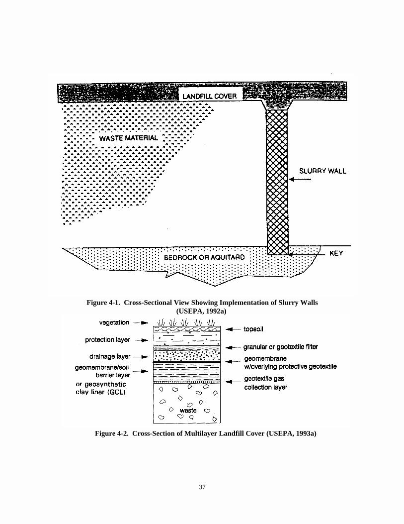
37
Figure 4-2. Cross-Section of Multilayer Landfill Cover (USEPA, 1993a)
Figure 4-1. Cross-Sectional View Showing Implementation of Slurry Walls(USEPA, 1992a)
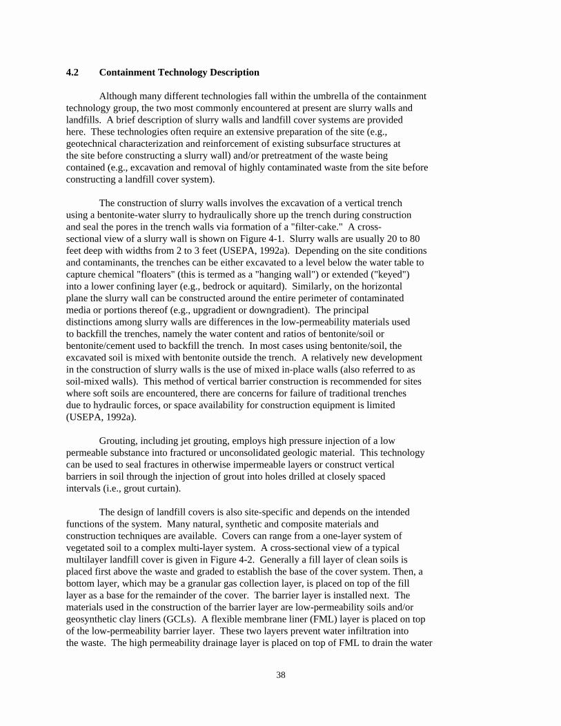
38
4.2 Containment Technology Description
Although many different technologies fall within the umbrella of the containmenttechnology group, the two most commonly encountered at present are slurry walls andlandfills. A brief description of slurry walls and landfill cover systems are providedhere. These technologies often require an extensive preparation of the site (e.g.,geotechnical characterization and reinforcement of existing subsurface structures atthe site before constructing a slurry wall) and/or pretreatment of the waste beingcontained (e.g., excavation and removal of highly contaminated waste from the site beforeconstructing a landfill cover system).
The construction of slurry walls involves the excavation of a vertical trenchusing a bentonite-water slurry to hydraulically shore up the trench during constructionand seal the pores in the trench walls via formation of a "filter-cake." A cross-sectional view of a slurry wall is shown on Figure 4-1. Slurry walls are usually 20 to 80feet deep with widths from 2 to 3 feet (USEPA, 1992a). Depending on the site conditionsand contaminants, the trenches can be either excavated to a level below the water table tocapture chemical "floaters" (this is termed as a "hanging wall") or extended ("keyed")into a lower confining layer (e.g., bedrock or aquitard). Similarly, on the horizontalplane the slurry wall can be constructed around the entire perimeter of contaminatedmedia or portions thereof (e.g., upgradient or downgradient). The principaldistinctions among slurry walls are differences in the low-permeability materials usedto backfill the trenches, namely the water content and ratios of bentonite/soil orbentonite/cement used to backfill the trench. In most cases using bentonite/soil, theexcavated soil is mixed with bentonite outside the trench. A relatively new developmentin the construction of slurry walls is the use of mixed in-place walls (also referred to assoil-mixed walls). This method of vertical barrier construction is recommended for siteswhere soft soils are encountered, there are concerns for failure of traditional trenchesdue to hydraulic forces, or space availability for construction equipment is limited(USEPA, 1992a).
Grouting, including jet grouting, employs high pressure injection of a lowpermeable substance into fractured or unconsolidated geologic material. This technologycan be used to seal fractures in otherwise impermeable layers or construct verticalbarriers in soil through the injection of grout into holes drilled at closely spacedintervals (i.e., grout curtain).
The design of landfill covers is also site-specific and depends on the intendedfunctions of the system. Many natural, synthetic and composite materials andconstruction techniques are available. Covers can range from a one-layer system ofvegetated soil to a complex multi-layer system. A cross-sectional view of a typicalmultilayer landfill cover is given in Figure 4-2. Generally a fill layer of clean soils isplaced first above the waste and graded to establish the base of the cover system. Then, abottom layer, which may be a granular gas collection layer, is placed on top of the filllayer as a base for the remainder of the cover. The barrier layer is installed next. Thematerials used in the construction of the barrier layer are low-permeability soils and/orgeosynthetic clay liners (GCLs). A flexible membrane liner (FML) layer is placed on topof the low-permeability barrier layer. These two layers prevent water infiltration intothe waste. The high permeability drainage layer is placed on top of FML to drain the water
39
away that percolates through the top of the cover. A granular or geotextile filter fabricmay be laid on top of the drainage layer for protecting the drainage layer from cloggingdue to fine silts or clay deposits from the percolating water. A protective fill soil andtopsoil are then applied and the topsoil seeded with grass or other vegetation adapted tolocal conditions. Covers are usually constructed in a crowned or domed shape with sideslopes as low as is consistent with good stormwater runoff characteristics. Othermaterials may be used to increase slope stability. Steeply mounded landfills can have anegative effect on the construction and stability of cover. For example, there may bedifficulty anchoring a geomembrane to prevent it from sliding along the interfaces of thegeomembrane and soils.
Landfill covers are presently constructed in a variety of combinations dependingupon the site-specific conditions. The most critical components of a cover with respectto selection of materials are the barrier layer and the drainage layer. The barrier layercan be a GCL and/or low-permeability soil (clay). Other alternative barrier materialshave also been identified in the document (USEPA, 1993a) cited under reference.
4.3 Cross-Media Transfer Potential of Containment Technologies
(a) General
General cross-media transfer potentials during site preparation, pre-treatment,and post-treatment activities have been addressed in Chapter 2.
(b) Additional Concerns for Specific Containment Technologies
In addition to the general concerns and BMPs that are outlined in Chapter 2,containment technologies pose the following technology-specific concerns:
& Geomembranes are vulnerable to puncturing during installation. Inadequate preparation of the surface on which the geomembrane willbe laid, or improper placement of materials on top of the geomembranemay result in punctures that allow infiltration of water and escapeof volatile contaminants. Proper seaming of adjacent sheets also iscritical for effective containment using this technology (Rumer andRyan, 1995).
& Landfill cover systems pose the same cross-media transfer potentialas geomembrane liners. Breaches in the system's integrity couldallow infiltration of rain water. The infiltration could thenresult in leaching of contaminants from the waste into surroundingsoil and underlying groundwater. VOCs may also escape from thelandfill cover system by diffusion through the cover layers and by"barometric pumping" through vents (USEPA, 1992c). Breaches in thelandfill cover system and improper design and installation oflandfill gas collection systems also could allow volatilecontaminants to escape into the atmosphere.
40
& Since salt bed disposal is a deep underground entombment ofcontaminants, potential for releases are minimal. However,improper storage and handling of the wastes before placing them inthe deep underground vaults could cause aboveground migration ofcontaminants.
4.4 Best Management Options to Avoid Potential Cross-Media Transfers for ContainmentTechnologies
General BMPs to prevent potential cross-media transfer of contaminants duringsite preparation, pre-treatment, and post-treatment activities have been addressed inChapter 2. Only technology-specific treatment activities and possible BMP options tocontrol cross-media transfer of contaminants during these activities are furnishedbelow.
Containment Treatment Activities - During implementation of the containmenttechnologies the following activities are most commonly undertaken:
® Excavation; trenching; storage of soils, sediments, and materials thatwill be used to construct containment system; construction of slurrywalls, landfill covers, and other containment units. In the case of deepcontainment, such as with salt beds, extensive underground excavation isrequired Secondary activities include surface water diversion andcontrol, on-site pumping and treating, installation of cut-off trench typeinterceptors, installation of leachate collection systems.
During these activities, the following BMPs should be considered for containmenttechnologies:
7 In the case of slurry walls, when there is a potential for outward migrationand contamination of groundwater, periodic pumping and treating of thecontaminants from the contained area and maintaining an inward hydraulicgradient from outside to inside the slurry wall may be considered. Thispractice has been observed in the field during field validation of BMPs (seeSection 11.7.1).
7 All soils should be analyzed and processed before they are disposed of off-site (see Section 11.7.2).
7 Air quality trends should be constantly monitored. If air quality degradesas a result of construction activities, those activities should be alteredor stopped until air quality is restored (see Section 11.7.2).
7 Climatological extremes (e.g., high wind) should be considered whenimplementing containment technologies. See Chapter 2, Section 2.2.2, fordetails on consideration of climatological extremes.
7 All debris should be covered during construction (see Section 11.7.2).
41
7 Temporary sumps should be used to collect stormwater runoff from the siteduring construction (see Section 11.7.2).
7 Temporary arrangements should be provided that protect areas that arevulnerable to damage and migration of contaminants during construction(e.g., road covers). See Chapter 3 and Section 11.7.2 for more details.
7 Effective VOC, methane, and odor emissions should be controlled by usingcovers, foam suppressants, enclosures, vapor collection systems, gasflares, or other methods as appropriate (USEPA, 1992b).
7 Contaminated liquids generated from treatment operations should be treatedand/or disposed in a protective manner as specified in Chapter 3 and Chapter6, Section 6.4, of this document.
Additional Post-Treatment Activities - In addition to the general post-treatmentBMPs provided in Chapter 2, the following BMPs should be considered for containmenttechnologies:
7 Routine audits should be conducted to verify the integrity of thecontainment structure with accompanying documentation.
7 For most containment technologies, the production of residuals isgenerally not a concern. However, construction of soil-bentonite slurrywalls can generate large quantities of excess slurry and excavatedmaterials. In most cases, it is expected that these excess materials arenot hazardous (Freeman and Harris, 1995). However, if the excavated soiland slurry cannot be used as backfill, they should be properly stored onsiteor transported and disposed offsite.
4.5 Waste Characteristics that May Increase the Likelihood of Cross-MediaContamination for Containment Technologies
The effectiveness of containment technologies could be compromised and unduecross-media contamination may be caused under certain conditions identified in thissubsection. However, some of these limitations could possibly be overcome with varioustechnology specific modifications and variations. Please refer to technology-specificreferences provided at the end of this chapter for additional information aboutmodifications or variations that can be used to enhance the effectiveness of containmenttechnologies.
� When contaminant concentrations exceed 10% to 25% of their explosivelimits, they are potentially unsafe to handle or can pose a threat to theintegrity of the containment system (USEPA, 1994).
� Ignitable wastes may present fire hazards when treated using containmenttechnologies that are exothermic (generates heat).
42
� Very low pH values (<4.0 Standard Unit (SU)) or high (> 11 SU) may lead tocorrosion in liners and equipment (USEPA, 1994).
� Strong oxidizers can corrode slurry walls and geomembranes.
4.6 References
1. Freeman, Harry M. and Eugene F. Harris. 1995. Hazardous Waste Remediation: Innovative Treatment Technologies. Technomic Publishing Co., Inc., Lancaster,PA.
2. Rumer, R.R. and M.E. Ryan. 1995. Barrier Containment Technologies forEnvironmental Remediation Applications, John Wiley and Sons, Inc., August.
3. U.S. Department of Energy (DOE). 1995. Draft No Migration Variance Petition,Waste Isolation Pilot Plant, DOE/CAO-95-2043, Carlsbad Area Office, Carlsbad, NM. May.
4. USEPA. 1994. BMP Development Workshop Summary - Containment Technologies. Officeof Solid Waste, Permits and State Programs Division, August.
5. Dutta, S. 1993. Modified Cover System for Hazardous Waste Landfills in Semi-AridAreas, Proceedings of the 3rd International Conference on Case Histories inGeotechnical Engineering, St. Louis, MO, June.
6. USEPA. 1993a. Engineering Bulletin-Landfill Covers. EPA/540/S-93/500. Officeof Research and Development, Cincinnati, February.
7. USEPA. 1993b. Environmental Fact Sheet, Controlling the Impacts of RemediationActivities in or Around Wetlands, EPA/530/F-93/020, Office of Solid Waste andEmergency Response/Office of Waste Programs Enforcement, August.
8. USEPA. 1992a. Engineering Bulletin-Slurry Walls, EPA/540/S-92/008, Office ofResearch and Development, Cincinnati, October.
9. USEPA. 1992b. Engineering Bulletin, Control of Air Emissions from MaterialsHandling During Remediation, EPA/540/2-91/023, October.
10. USEPA. 1992c. Organic Air Emissions from Waste Management Facilities, EPA/625/R-92/003, May.
11. USEPA. 1991a. Handbook, Stabilization Technologies for RCRA Corrective Actions, EPA/625/6-91/026, Office of Research and Development, Washington, DC, August.
12. USEPA. 1991b. SITE Technology Demonstration Summary, International WasteTechnologies/Geo-Con In Situ Stabilization/Solidification Update Report,EPA/540/S5-89/004a, Center for Environmental Research Information, Cincinnati,OH.
43
13. USEPA. 1989. Technical Guidance Document, Final Covers on Hazardous WasteLandfills and Surface Impoundments, EPA/530/SW-89/047, Office of Solid Waste andEmergency Response, Washington, DC.
44
Soil washing (for BMPs) is an ex situ, generally water-based process thatrelies on traditional chemical and physical extraction and separation processes forremoving a broad range of organic, inorganic, and radioactive contaminants from soilsor solid media (USEPA, 1993a). This aqueous-based technology uses mechanicalprocesses (e.g., scouring) and/or solubility characteristics of contaminants toseparate contaminants from excavated soils or solid media. The process frees andconcentrates contaminants in a residual portion of the soil (typically 5 to 40% of theoriginal volume), where they can be subsequently treated by other remediationtechniques or managed in compliance with applicable regulations.
5.0 Chapter Five: BMPs for SOIL WASHING
This chapter focuses on the generally accepted best management practices (BMPs) tominimize cross-media transfer of contaminants during remedial actions or correctivemeasure implementations when using soil washing technologies to treat soils or othersolid media. BMPs are meant only to provide guidance and general recommendations on theoperational practices of selected technologies. BMPs are not meant to direct or dictatethe selection of appropriate technologies.
5.1 Definition and Scope of Soil Washing (for BMPs)
A typical schematic of a soil washing system is shown on Figure 5-1.
Because of their similarity in cross-media transfer potentials the followingtreatment technologies are listed as a few examples of soil washing technologies (for thepurpose of BMPs):
& Soil Washing & Excavating, Dredging, and& Solvent Extraction Conveying& Debris Washing & Wet and Dry Screening& Magnetic Separation & Gravity Concentration
& Froth Flotation
The scope of BMPs for soil washing is not limited to the above listed technologies. Any treatment technology that satisfies the key features of soil washing could beconsidered as soil washing technologies for the purpose of BMPs. BMPs for soil flushingtechnologies and other in situ technologies are addressed under Chapter 10 of thisdocument. Solvent extraction has been included in this chapter because the treatmentprocess closely matches the key features of this BMP category.
5.1.1 Key Features of Soil Washing Technology for the Purpose of BMPs
& A non-destructive process which separates contaminants from solidsand concentrates the contaminants for collection and/or treatment.
& An ex situ technique normally requiring excavation of soil orsediment and other materials handling operations, such as pre-
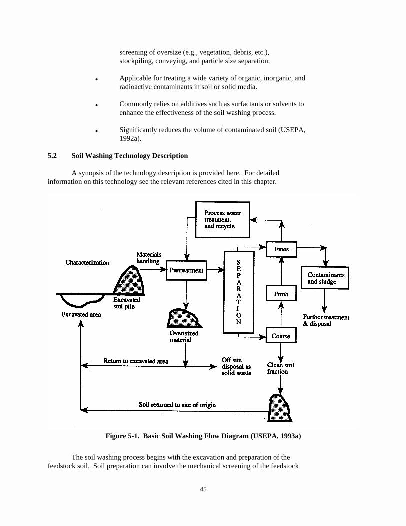
45
Figure 5-1. Basic Soil Washing Flow Diagram (USEPA, 1993a)
screening of oversize (e.g., vegetation, debris, etc.),stockpiling, conveying, and particle size separation.
& Applicable for treating a wide variety of organic, inorganic, andradioactive contaminants in soil or solid media.
& Commonly relies on additives such as surfactants or solvents toenhance the effectiveness of the soil washing process.
& Significantly reduces the volume of contaminated soil (USEPA,1992a).
5.2 Soil Washing Technology Description
A synopsis of the technology description is provided here. For detailedinformation on this technology see the relevant references cited in this chapter.
The soil washing process begins with the excavation and preparation of thefeedstock soil. Soil preparation can involve the mechanical screening of the feedstock
46
to remove rocks, debris, and other oversized material (USEPA, 1993a). The treatmentprocess generally involves the use of wet, mechanical scrubbing and screening processesto separate particles containing the contaminants. Most commercially available soilwashing systems utilize mechanical screening devices to remove oversize materials andseparation systems to generate coarse- and fine-grained fractions. The process alsoincludes treatment units for washing and systems for scrubbing the separated fractions. The specific processes and equipment used depend upon individual site characteristics.
After excavation and preparation, the feedstock soil is actively mixed with wateror an amended water-based washing fluid, which separates the contaminants from the soil. The soil is then separated from the spent fluid, and the soil is recovered in two distinctfractions. One fraction comprises a relatively high volume, coarse sand and gravelfraction that is clean and suitable for use as on-site fill; the other usually comprises asmaller volume, fine silt and clay fraction that typically carries the bulk of thecontaminants. From the coarse soil fraction, a contaminated, naturally occurringorganic material may be separated as a third fraction by specific gravity separation. Thecoarse sand and gravel fraction is generally passed through an abrasive scouring orscrubbing action to remove the surficial contamination. The washwater in this washingstep may contain a basic leaching agent, surfactant, or chelating agent to help removeorganics or heavy metals. The mixture is agitated by use of high-pressure water jets,vibration devices, and other means depending upon the equipment (USEPA, 1991a). Fineparticles are sometimes further separated in a sedimentation tank with the help of aflocculating agent.
In the final step, the remaining fine silt, clay and the contaminated washwater aretreated. The contaminated washwater may require precipitation and clarification, whichremoves metals and fine soils as a sludge. The fine soils, in which contaminants have beenconcentrated, will normally require further treatment or proper disposal in compliancewith applicable regulations.
To increase the efficiency of contaminant removal, sometime chemical agents areadded to the washwater. Acids, such as hydrochloric acid, sulfuric acid, and nitric acid,may be added to improve the solubility of certain contaminants, especially heavy metals.Sodium hydroxide, sodium carbonate, and other bases can be used to precipitatecontaminants in the extraction fluid. Dispersion of oily contaminants can be facilitatedby the addition of surface active agents. Various chelating agents such as citric acid,ammonium acetate, nitrilotriacetic acid (NTA), and ethylenediaminetetraacetic acid(EDTA) will remove the available fraction of inorganic contaminants (USEPA, 1991a). Forimproved removal in certain cases, the extraction temperature is elevated or an oxidizer,such as hydrogen peroxide, or ozone is added for chemical oxidation.
5.3 Cross-Media Transfer Potential of Soil Washing Technologies
(a) General
General cross-media transfer potentials during site preparation, pre-treatment,and post-treatment activities have been addressed in Chapter 2.
(b) Additional Concerns for Soil Washing Technologies
47
& Additives used in the process can increase the potential of directspillage of wastewater (e.g., foam with metals and organics) to thesoil and surface water during treatment activities, especially ifsoil washing unit is not properly lined and bermed.
& In the specific case of solvent extraction, where there are commonlypressurized tanks and flammable and highly volatile solvents used,there is potential for VOC emissions due to leaks in pipes, joints,and valves. Major emission points associated with solventextraction are those involved in the distillation process used torecover the solvent (USEPA, 1992b).
& Chelating agents, surfactants, solvents, and other additives areoften difficult and expensive to recover or recycle from the spentwashing fluid by conventional treatment processes, such as,settling, chemical precipitation, or activated carbon. Thepresence of additives in the contaminated soil and treatment sludgeresiduals may cause added difficulty in disposing of these residuals(USEPA, 1993a), thereby increasing the potential for cross-mediatransfer.
& Additives used in the soil washing, debris washing, wet screeningand froth flotation process can increase the potential of directspillage of wastewater to the soil and surface water duringtreatment activities as a direct result of excessive foaming orfrothing.
& Soil characterization data (e.g., size classifications, levels ofcontamination, permeability of soil, and estimates of thequantities of soil) used for treatability or pilot-scale tests maynot accurately reflect the breadth of soil characteristics actuallyfound in the field. Accurate characterization is important for theefficient use of this technology and additional pretreatment of thesoil (i.e., additional drying, crushing and sizing) may be necessaryjust prior to operating the technology. Such impropercharacterization or lack of adequate pre-treatment may lead to ahigher potential for cross-media transfer than expected.
& Treated soil residues from soil washing, wet and dry screening,gravity concentration and froth flotation may have significantlydifferent soil characteristics such as permeability andcompactability, and thus, could adversely effect the ground waterflow characteristics of the site where these soils are replaced. Other constituents at the site could then migrate back into orthrough the treated soil.
& Wastewaters from soil washing, wet screening, froth flotation anddebris washing may contain diluted amounts of the hazardousconstituents and significant levels of suspended matter. Cross-
48
media transfer can occur if these residues are released to theenvironment without any treatment.
& Improper or incomplete identification of contaminants and lack ofknowledge of their concentrations in the spent washwater may foul upthe system since the washwater is treated and recycled back into thewashing process. This may in turn cause inadequate cleaning andremoval of contaminants and cause cross-media transfer.
& When the fine particles are not separated from the pre-treatedsoils, it may result in emission of the fine particles, whichoftentimes bind most of the contaminants.
5.4 Best Management Options to Avoid Potential Cross-Media Transfers for Soil WashingTechnologies
General BMPs to prevent potential cross-media transfer of contaminants duringpre-treatment and post-treatment activities have been addressed in Chapter 2. Onlytechnology specific treatment activities and possible BMP options to control cross-mediatransfer of contaminants during treatment, as well as a few post-treatment BMPs, arefurnished below.
During the soil washing treatment process, the following activities are mostcommonly undertaken:
® Excavation of soils, temporary storage, particle size separation,transportation/transfer of contaminated soils from loaders to dump trucks,mixing action, movement of the contaminated media through a conveyorsystem, desorption, separation, and washing in an aqueous media.
The following BMPs, when appropriate, are recommended to prevent cross-mediatransfer of contaminants for the above activities:
7 Precautions should be taken to avoid foaming (or frothing) and subsequentoverflow by periodically performing visual inspections when additives areused that have been demonstrated to froth in other situations. Fieldtesting of small soil samples in jars with excess additives might helpanticipate problems, but should not be used as the only means to anticipatefrothing problems. As a contingency plan, the area underneath the soilwashing unit could also be lined and bermed to collect any potentialspillage.
7 Major emission points associated with solvent extraction, such as, thoseinvolved in the distillation process for recovering solvent, should becarefully monitored during operation. Process shutdowns may be deemednecessary if excessive levels are detected.
7 Volumes of soil batches should be carefully managed so that they do notoverfill the containers or exceed the normal operating specification of the
49
equipment. The soil batches should preferably be run at less than maximumcapacity to prevent leaks or spills.
7 Chelating agents, surfactants, solvents, and other additives should becarefully selected so as to avoid ones that are difficult and expensive torecover or treat by conventional processes, such as, settling, chemicalprecipitation, or activated carbon. Potential impact of residual soilwashing additives that are anticipated to remain in the soil aftertreatment should be examined and replacement plans be adjusted accordingly(e.g., if acids are used to extract metals from soils, the residual soil mayneed to be either limed prior to replacement in order to account for theacidity expected to be left in the soil or a neutralization step may need tobe included as part of the soil washing process.)
7 Any off-site runoff should generally be prevented from entering and mixingwith the on-site contaminated media by building earthen berms or adoptingsimilar other measures. Provision should be made to capture the on-sitesurface water runoff by diverting it to a controlled depression-area orlined pit.
7 Most soil washing operations are vulnerable to high wind, especially withrespect to the fugitive dust emission. Weather monitoring and operationalcontrol should be exercised as specified in Chapter 2 of this document. During excavation and material handling activities as well, meteorologicalconditions should be strongly emphasized and evaluated to minimize cross-media transfer.
7 Mixing, crushing, or conveying activities should generally be conductedunder an environment where the off gases, volatiles, dusts, etc. are allcaptured inside a hood or cover or controlled using other control optionslisted in Chapter 3. The VOC emissions associated with these activitiesshould be controlled by capturing and then treating the captured vapor/air.
7 All excavated soils when stored prior to treatment should be securelycovered with plastic liners and these temporary covers need to bemaintained until the storage pile is moved for treatment. The excavatedcells should also be lined, when migration possibilities of contaminatedrunoff exist, during precipitation events.
7 During the main treatment activities as specified above, organic orinorganic vapor emissions should be monitored and appropriate emissioncontrol measures, described in Chapter 3 of this document, should be used toprevent emissions above the allowable level specified by the regulatoryagency (EPA or authorized state).
7 When treating soils contaminated with explosive wastes, proper safety andcare should be exercised to prevent any explosion during the treatmentprocess. For conducting safe operations, recommendations provided in theHandbook (USEPA, 1993c) may be used, when necessary.
50
7 Periodic system monitoring and evaluation should be performed, ifappropriate, to prevent leaks or spills.
7 When re-using treated soils for restoration of a site, care should be takento re-create the original soil texture. The anticipated soilcharacteristics of the treated soil should be verified prior toreplacement. This may require the addition of clays, nutrients, or othermaterials, some of which can be mixed in from clean soils at the site. During these soil mixing activities, BMPs for pre-treatment should beapplied (i.e., use covers over areas used for storage or mixing or forprocessing small batches; minimize work in high temperatures or in highwind, etc.).
7 There are four main waste streams generated during soil washing: contaminated solids from the soil washing unit, wastewater, wastewatertreatment sludges and residuals, and air emissions (Freeman and Harris,1995). General BMPs for addressing these residuals are provided in Chapter2; additional BMPs are provided here.
— When collecting moisture or liquids from the treatment process, thecontaminated aqueous stream should generally be collected in a tankor a lined/containment system. This should prevent the contaminantsfrom mixing with the normal surface water runoff from the area andthe surrounding natural watercourse. The contaminated aqueousstream should be treated or disposed of in accordance with theapplicable regulation.
— An enclosed conveyance system, such as a pipeline or hose, should beused to move contaminated liquids from the soil washing unit to thecontainers that will be used to store them.
— Containers that hold residual liquids should be stored in a place inwhich they cannot be disturbed or ruptured by large equipment. Thismay require construction of a residuals management unit separatefrom the treatment and storage areas.
— During post-treatment, residuals that are nearly pure listed waste(contaminant) or highly concentrated may need to be managed. Thesewastes should be dealt with extreme caution and safety to avoid allpossible risks of cross-media transfer of contaminants and treatedor disposed of in compliance with the applicable state and/orfederal regulations.
— Wastewaters containing the hazardous constituents and the highlevels of suspended matter can generally be treated withconventional wastewater technologies to acceptable regulatorylevels. They should generally be handled on-site as potentiallyhazardous wastewaters with appropriate spill preventioncontingencies. Air emissions from these units should also be
51
evaluated for appropriate control measures (i.e., closed tanks,covers, etc.) as specified in Chapter 3.
— If solid materials such as granulated carbon filters are used, theyshould be removed carefully from the emissions system to avoidrupturing them and dissipating the carbon materials. They should beplaced into tightly covered containers until they can be recycled orproperly disposed of.
5.5 Waste Characteristics that May Increase the Likelihood of Cross-MediaContamination for Soil Washing Technologies
The effectiveness of soil washing treatment technologies could be compromised andundue cross-media contamination may be caused under certain conditions identified inthis subsection. Some soils, especially those that are rich in clays or contain highconcentrations of mineralized metals or hydrophobic organics, require very large amountsof additives to achieve acceptable remediation endpoints. Additionally, complexmixtures of contaminants in the soil may make it difficult to formulate a single suitablewashing fluid that will remove all the different contaminant types. In such cases, multiple cleaning fluids may need to be used, and therefore multiple types of residualswill be generated.
When soil washing is used to remediate contaminated soil, one should consider thepotential for the generation of large amounts of hazardous wastes that must be treated ordisposed of (sometimes at a great cost) when this technology is used in less than idealsituations. In such cases, even when best management practices are applied, thesignificant volumes of hazardous wastes that are generated and the reduced efficiencywith which the overall system is operating can increase the risk of accident ormismanagement, which can in turn increase the risk of cross-media contamination.
However, some of these limitations could possibly be overcome with varioustechnology specific modifications and variations, and some of these limitations couldpossibly be overcome by coupling with other processes (such as further separation offines, using special solvents, etc.), but may involve higher cost. The following fewcharacteristics have been identified that could impede the soil washing treatmentprocess and may result in cross-media transfer of contaminants.
� Soils with high silt and clay content (>50% clay and silt) may beproblematic due to the difficulty of removing contamination from very fineparticles (Lear, 1996, and USEPA, 1993a).
� Soils contaminated with a high concentration of mineralized metals orhydrophobic organics (USEPA, 1993a).
� Complex mixtures of contaminants make it difficult to formulate a suitablewashing fluid that will remove all the different contaminant types, andpossibly be cost prohibitive. Sometimes a single contaminant/compoundcould also become strongly bound and difficult to remove (USEPA, 1993a).
52
� Generally not designed for highly explosive materials.
5.6 References
1. Lear, Paul R. 1996. OHM Remediation Services Corp. Comments on Draft BMPDocument. Personal Communication with Subijoy Dutta, May.
2. U.S. Department of Energy (DOE). 1995. Draft No Migration Variance Petition,Waste Isolation Pilot Plant, DOE/CAO-95-2043, Carlsbad Area Office, Carlsbad, NM,May.
3. Freeman, Harry M. and Eugene F. Harris. 1995. Hazardous Waste Remediation: Innovative Treatment Technologies, Technomic Publishing Co., Inc., Lancaster,PA.
4. USEPA. 1994a. BMP Development Workshop Summary-Soil Washing and ThermalTreatment, Office of Solid Waste, Permits and State Programs Division, August.
5. USEPA. 1994b. Engineering Bulletin-Solvent Extraction, EPA/540/S-94/503,Office of Research and Development, Cincinnati, April.
6. USEPA. 1993a. William C. Anderson, ed. Innovative Site Remediation Technology,Soil Washing/Soil Flushing, Volume 3, EPA 542/B-93/012, Office of Solid Waste andEmergency Response.
7. USEPA. 1993b. Proposed Best Demonstrated Available Technology (BDAT) BackgroundDocument for Hazardous Soil, Office of Solid Waste, Waste Management Division,August.
8. USEPA. 1993c. Approaches for the Remediation of Federal Facility SitesContaminated with Explosive or Radioactive Wastes, EPA/625/R-93/013, Office ofResearch and Development, Washington, DC, September.
9. USEPA. 1992a. A Citizen's Guide to Soil Washing-Technology Fact Sheet,EPA/542/F-92/003, Office of Solid Waste and Emergency Response, TechnologyInnovation Office.
10. USEPA. 1992b. Seminar Publication-Organic Air Emissions from Waste ManagementFacilities, EPA/625/R-92/003, Office of Research and Development, Washington,DC, August.
11. USEPA. 1991a. Guide for Conducting Treatability Studies Under CERCLA: SoilWashing, Interim Guidance (and Quick Reference Fact Sheet), EPA/540/2-91/020A andB, Office of Emergency and Remedial Response, September.
12. USEPA. 1991b. Innovative Treatment Technologies-Overview and Guide toInformation Sources, EPA/540/9-91/002, Office of Solid Waste and EmergencyResponse, Washington, DC, October.
53
13. USEPA. 1990a. Engineering Bulletin-Solvent Extraction Treatment, EPA/540/2-90/013, Office of Research and Development, Cincinnati, September.
14. USEPA. 1990b. Engineering Bulletin-Soil Washing Treatment, EPA/540/2-90/017,Office of Research and Development, September.
15. USEPA. 1989. Overview: Soils Washing Technologies for CERCLA, RCRA, and LeakingUST Site Remediation, Risk Reduction Engineering Laboratory, Edison, NJ, June.
54
Thermal treatment processes employ indirect or direct heat exchanges todesorb, vaporize, or separate volatile or semi-volatile organics from soils or anysolid media while largely avoiding combustion (destruction) of these contaminants inthe primary unit. Gases or vapors from the thermal process are treated, destroyed orcondensed for reuse. (USEPA, 1993a and 1994c)
6.0 Chapter Six: BMPs for THERMAL TREATMENT
This chapter focuses on the generally accepted best management practices (BMPs) tominimize cross-media transfer of contaminants during remedial actions or correctivemeasure implementations when using thermal treatments to treat soils or solid media. BMPs are meant only to provide guidance and general recommendations on the operationalpractices of selected technologies. BMPs are not meant to direct or dictate the selectionof appropriate technologies.
6.1 Definition and Scope of Thermal Treatment (for BMPs)
Many types of thermal treatment technologies are currently being used for thetreatment of soils and solid media. Considering their similarity in cross-media transferpotentials, the following treatment technologies are listed as a few examples of thermaltreatment (for BMPs):
& Thermal Desorption & Low Temperature Thermal Aeration& Catalytic Oxidation & Anaerobic Thermal (ATP)& Thermal Bonding & Rotary Desorbers& Molten Salt Oxidation & Heated Conveyors& LT System & Anaerobic Pyrolysis3
Two technologies included in this group -- molten salt oxidation and anaerobicpyrolysis -- differ slightly from the others, but have been included here because theyresemble these technologies more than any others addressed in this guidance. However,unlike the other technologies in this group, molten salt oxidation and anaerobicpyrolysis destroy at least some portion of the contaminants present in the soil or solidmedia.
The scope of BMPs for thermal treatment is not limited to the above listedtechnologies. Any treatment technology that meets the key features of thermal treatmentshould generally be considered as thermal treatment for the purpose of BMPs. BMPs forincineration technologies are addressed separately under Chapter 9 of this document.
A typical schematic of a thermal desorption system is shown in Figure 6-1.
6.1.1 Key Features of Thermal Treatment for the Purpose of BMPs
& External application of heat to raise the operating temperature isthe unique feature of the thermal treatment category for the purposeof BMPs.
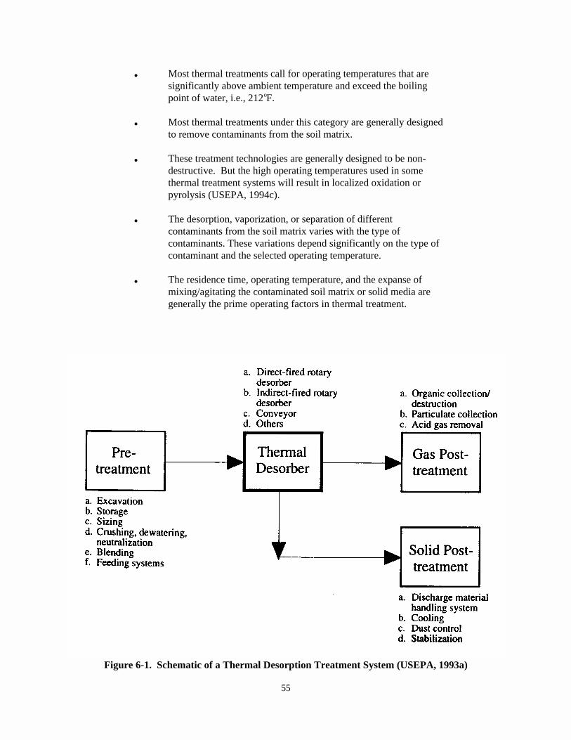
55
Figure 6-1. Schematic of a Thermal Desorption Treatment System (USEPA, 1993a)
& Most thermal treatments call for operating temperatures that aresignificantly above ambient temperature and exceed the boilingpoint of water, i.e., 212 F.o
& Most thermal treatments under this category are generally designedto remove contaminants from the soil matrix.
& These treatment technologies are generally designed to be non-destructive. But the high operating temperatures used in somethermal treatment systems will result in localized oxidation orpyrolysis (USEPA, 1994c).
& The desorption, vaporization, or separation of differentcontaminants from the soil matrix varies with the type ofcontaminants. These variations depend significantly on the type ofcontaminant and the selected operating temperature.
& The residence time, operating temperature, and the expanse ofmixing/agitating the contaminated soil matrix or solid media aregenerally the prime operating factors in thermal treatment.
56
6.2 Thermal Treatment Technology Description
Thermal desorption is considered the most general and representative form ofthermal treatment for the purposes of this chapter; therefore, a description of thermaldesorption is provided here.
In thermal desorption, contaminated material is excavated and delivered to thedesorption unit. Excavated material is often stockpiled to provide an adequate feedsupply for continuous operation of the treatment facility. Typically, before anytreatment, large objects are screened from the medium and rejected. Rejected materialcan sometimes be sized and recycled to the desorber feed. The medium may then be treatedto adjust pH and moisture content. The medium is then delivered by gravity to the desorberinlet or conveyed by augers to a feed hopper from which it is mechanically conveyed to thedesorber. In the desorption unit, the contaminated material is heated, and water andcontaminants are volatilized. An inert gas may be injected as a sweep stream. Organics inthe off-gas may be collected and recovered by condensation and adsorption, or burned in anafterburner (USEPA, 1993a).
To increase the effectiveness of thermal desorption technology, extensive pre-processing/pre-treatment of the inlet soil may be conducted. This pre-processing mayinclude removing rocks and debris from the waste matrix, mixing the waste to create a morehomogeneous feed, and screening and crushing the waste matrix to achieve a smallerparticle size. During pre-processing, air emission monitoring must be conducted tocontrol fugitive emissions (USEPA, 1990).
Operation of thermal desorption systems can create a number of process residualstreams that may need to be managed: treated media; untreated, oversized rejects;condensed contaminants and water; particulate control-system dust; clean off-gas; andspent carbon or other media, if used (USEPA, 1993a).
6.3 Cross-Media Transfer Potential of Thermal Treatment Technologies
(a) General
Environmental impacts associated with all thermal desorbers, aside from processemissions,are attributable to excavation of contaminated solids, management of treated solids, andequipment noise (USEPA, 1993a).
General cross-media transfer potentials during site preparation, pre-treatment,and post-treatment activities have been addressed in Chapter 2.
(b) Additional Concerns for Thermal Treatment Technologies
& During various thermal treatment operations, SVOC/VOC emissionscan occur from leaks in pipes, joints, valves, and uncoveredconveyor systems.
57
& Stack emissions from the collection or destruction of vapors pastthe thermal desorption, vaporization, or separation treatment unitcan release contaminants into the air at levels above the regulatorylimit.
& The discharge of scrubber liquor and blowdown can releasecontaminants to air, water, or soils.
& Waste handling can contribute significantly to VOC emissions duringremediation of soils or solid media with thermal treatments.
& Inadequate control and management of baghouse dust containing ash,metals, and/or unoxidized compounds may also cause contaminants tobe released into the environment.
& When using any thermal treatment for remediation of explosivewastes, there is potential for possible explosion or detonation ofthe waste during the treatment process.
& When radioactive/mixed wastes are remediated by thermal treatment,the radionuclides are generally retained or bonded and renderedunleachable for safe disposal of the solid residuals (e.g., ash) inlandfills. Potential for radioactive emission from the treated massmay still exist.
& Fugitive emissions from fuel sources can sometimes add to theoverall emissions of organics from the site.
& In cases where organic wastes are extracted or concentrated using athermal treatment technology (i.e., rather than destroyed) the VOCemissions from these wastes can significantly increase the need forcontrol of VOCs from the overall process.
& During remediation of chlorinated organics using the AnaerobicThermal Processor or any other thermal treatment, the potentialexists for the creation of dioxin or dibenzo-furans emissions at lowconcentrations. Fugitive VOC emissions from the vapor coolingsystem are also possible (USEPA, 1993a).
6.4 Best Management Options to Avoid Potential Cross-Media Transfers for ThermalTreatment Technologies
General BMPs to prevent potential cross-media transfer of contaminants duringcleanup activities have been addressed in Chapter 2. Also, proper system design isrecommended prior to implementation of the remedial treatment to avoid cross-mediatransfer problems during different treatment steps. However, BMP options to controlspecific cross-media transfer of contaminants for thermal treatments are furnishedbelow.
58
During the thermal treatment process the following activities are most commonlyundertaken:
® Application of heat in a heat exchanger unit; rotational or other mixingaction; movement of the contaminated media through a conveyor system;vaporization, desorption, separation, or permanentbonding/solidification of contaminants.
To prevent cross-media transfer of contaminants the following BMPs arerecommended, where appropriate:
7 Fuel storage and fuel handling areas may be added under monitoring andemission control oversight if deemed necessary.
7 Routine inspections of pipes, valves and fittings should be performed wherefuel or pressurized liquids are involved.
7 During the main treatment activities as specified above, organic orinorganic vapor emissions should be monitored and appropriate emissioncontrol measures, described in Chapter 3 of this document, should be used toprevent emissions above the allowable level specified by the regulatoryagency (EPA or authorized state).
7 Technology design should take corrosion into account and incorporatecorrosion resistant surfaces for all appropriate pipes, valves, fittings,tanks, and feed systems. It is important that the air pollution controldevices are designed for the corrosive nature of the hot gases expected toenter them. Operational plans should include adequate inspectionprocedures that look specifically for corrosion and wear.
7 Operation of thermal desorption systems may create up to six processresidual waste streams: treated soil; oversized soil and debris rejects;condensed contaminants and water; spent aqueous and vapor phase activatedcarbon; and clean off-gas. The following BMPs can be used to control thepotential cross-media transfer of residuals:
— Treated medium, debris, and oversized rejects may be suitable forreuse onsite. If not, they should be properly stored orcontainerized until they can be treated and disposed of.
— The vaporized organic contaminants can be captured by condensationof the off-gas passing through a carbon absorption bed or othertreatment system.
— Liquid collection tanks and secondary containment should beincorporated into the operational plans. Plans should also be madefor subsequent treatment of these concentrated liquids inappropriately regulated units.
59
— Aqueous wastes from scrubber liquors and blowdown could beeffectively managed and controlled using a variety of wastewatertreatment technologies. See USEPA, 1987, 1986, and 1984 forinformation on wastewater treatment technologies. Technologyoperational plans should incorporate discussions of how movement ofthese liquids will be adequately controlled.
— Off-gas condensate may contain significant contamination and mayrequire further treatment (i.e., carbon absorption). If thecondensed water is relatively clean, it may be used to suppress thedust from the treated medium.
— Spent granulated carbon should either be returned to the supplierfor reactivation or incineration or regenerated onsite.
7 System monitoring and evaluation should be performed, as appropriate, todetermine possible emissions or migration of contaminants during treatmentactivities.
6.5 Waste Characteristics that May Increase the Likelihood of Cross-MediaContamination for Thermal Treatment Technologies
Under the following conditions the effectiveness of thermal treatmenttechnologies (as categorized for the purpose of BMPs) could be compromised, and couldcause undue cross-media contamination. However, some of these limitations couldpossibly be overcome with various technology specific modifications and variations.
� The contaminant concentration exceeding 10% to 25% of its lower explosivelimit (USEPA, 1994a).
� Corrosion in containers and equipment due to low (< 5 Standard Unit (SU)) orhigh (>11 SU) pH may pose problems (USEPA, 1994c).
� Particles greater than 2 inches in diameter may call for separate treatmentor disposal due to size limitations for most equipment used for thermaltreatment systems (USEPA, 1994c).
� Very high moisture content (>50%) generally makes most thermal treatmentshighly cost intensive, and might increase the potential for cross-mediarelease of contaminants through the vapor phase (USEPA, 1994c).
� Soils mixed with tars and organic materials greater than 10% by volume orweight may cause handling problems and thus may require use of a reactor orother equipment to process wastes, which could result in uncontrolledreleases due to corrosion (USEPA, 1994c).
6.6 References
60
1. USEPA. 1995. In Situ Remediation Technology Status Report: ThermalEnhancements, EPA/542/K-94/009, Office of Solid Waste and Emergency Response.
2. USEPA. 1994a. BMP Development Workshop Summary for Soil Washing and ThermalTreatment, Office of Solid Waste, Permits and State Programs Division, August.
3. USEPA. 1994b. William C. Anderson, ed. Innovative Site Remediation Technology,Thermal Destruction, Volume 7, EPA 542/B-94/003, Office of Solid Waste andEmergency Response.
4. USEPA. 1994c. Engineering Bulletin-Thermal Desorption Treatment, EPA/540/S-94/501, Office of Research and Development, Cincinnati, February.
5. Air & Waste Management Association (AWMA). 1993. Thermal II Changing Molecular &Physical Status, AWMA Live Satellite Seminar.
6. USEPA. 1993a. William C. Anderson, ed. Innovative Site Remediation Technology,Thermal Desorption, Volume 6, EPA/542/B-93/011, Office of Solid Waste andEmergency Response.
7. USEPA. 1993b. Approaches for the Remediation of Federal Facility SitesContaminated with Explosive or Radioactive Wastes, EPA/625/R-93/013, Office ofResearch and Development, Washington, DC, September.
8. USEPA. 1993c. Proposed Best Demonstrated Available Technology (BDAT) BackgroundDocument for Hazardous Soil, Office of Solid Waste, Waste Management Division,August.
9. USEPA. 1992a. Guide for Conducting Treatability Studies Under CERCLA: ThermalDesorption Remedy Selection, Interim Guidance (and Quick Reference Fact Sheet), EPA/540/R-92/074A and B, Office of Solid Waste and Emergency Response, September.
10. USEPA. 1992b. A Citizen's Guide to Thermal Desorption-Technology Fact Sheet, EPA/542/F-92/006, Office of Solid Waste and Emergency Response, TechnologyInnovation Office.
11. USEPA. 1991a. Innovative Treatment Technologies-Overview and Guide toInformation Sources, EPA/540/9-91/002, Office of Solid Waste and EmergencyResponse, October.
12. USEPA. 1991b. Engineering Bulletin-Thermal Desorption Treatment, EPA/540/2-91/008, Office of Research and Development, Cincinnati, May.
13. USEPA. 1990. Handbook on In Situ Treatment of Hazardous Waste-ContaminatedSoils, USEPA/540/2-90/002.
14. USEPA. 1988. Technology Screening Guide for Treatment of CERCLA Soils andSludges, EPA/540/2-88/004.
61
15. USEPA. 1987. Dewatering Municipal Wastewater Sludges Manual, EPA/625/1-87/014, Office of Research and Development, Cincinnati, September.
16. USEPA. 1986. Municipal Wastewater Disinfection Manual, EPA/625/1-86/021, Officeof Research and Development, October.
17. USEPA. 1984. Onsite Wastewater Treatment and Disposal Systems Manual,EPA/625/01-80/012, Office of Research and Development, October.
62
Vapor extraction involves use of vacuum pumps or blowers to produce a negativepressure gradient, which induces air flow through the waste matrix and causes movementof vapors containing volatile organic compounds (VOCs) towards extraction wells. VOCs in the pore spaces of soils or solid media are thereby removed and carried aboveground through screened extraction wells. Extracted vapors are treated, asnecessary, and discharged to the atmosphere or reinjected to the subsurface (wherepermissible). (USEPA, 1995a and 1991d).
7.0 Chapter Seven: BMPs for VAPOR EXTRACTION
This chapter focuses on the generally accepted best management practices (BMPs) tominimize cross-media transfer of contaminants during remedial actions or correctivemeasure implementations when using vapor extraction technologies to treat soils or solidmedia. BMPs are meant only to provide guidance and general recommendations on theoperational practices of selected technologies. BMPs are not meant to direct or dictatethe selection of appropriate technologies.
7.1 Definition and Scope of Vapor Extraction (for BMPs)
Because of their similarity in cross-media transfer potentials the followingtreatment technologies are listed as a few examples of vapor extraction technologies (forBMPs):
& Soil Vapor Extraction (SVE) & Soil Venting& Fracture Enhanced Vapor & Bioventing (also in Chapter
Extraction 8.0, Bioremediation)& Thermal Enhancements of SVE & Air Sparging& Steam Injection & Multi-Phase or Dual-Phase& Hot Air Injection Extraction& In Situ Steam Stripping
The scope of BMPs for vapor extraction is not limited to the above listedtechnologies. Any treatment technology that satisfies the key features of vaporextraction could be considered as vapor extraction for the purpose of BMPs.
Many of the above listed technologies are used in conjunction with vaporextraction or groundwater technologies, or may be used to remediate VOCs in saturatedsoils or groundwater. BMPs for bioventing systems are additionally addressed underChapter 8 (BMPs for Bioremediation) of this document.
A typical schematic of a vapor extraction system is shown in Figure 7-1.
7.1.1 Key Features of Vapor Extraction Technology for the Purpose of BMPs
& With respect to vadose zone soils, vapor extraction relies on theability to produce an advective air flow field throughout thecontaminated soils.
63
& The vacuum gradient created induces air flow through vadose zonesoils to volatilize contaminants.
& Transfers contaminants from soil to air. Vapor treatment followingvapor extraction from the subsurface may be required to minimizedischarge of contaminants to the atmosphere; however, it may not berequired in all cases.
& Generally does not destroy contaminants; extracts contaminantvapors for collection and/or treatment.
& Effectively reduces concentrations of volatile organic compounds(VOCs) and certain biodegradable semi-volatile organic compounds(SVOCs). Less volatile contaminants may be removed by bioventing. Heat (hot air or steam) may be applied to increase the volatility ofless volatile compounds (USEPA, 1995a).
& Generally, vapor extraction is an in situ technique (excludingabove-ground vapor and water treatment). It is primarily designedfor use in the vadose zone, although the saturated zone can bedewatered and treated or treated with air sparging combined withvacuum extraction.
& Vapor extraction can be used ex situ for the remediation ofaboveground soil piles. For this application, perforated pipes arelocated within the aboveground soil piles and connected to a blowerto draw air through the piles (USEPA, 1995a).
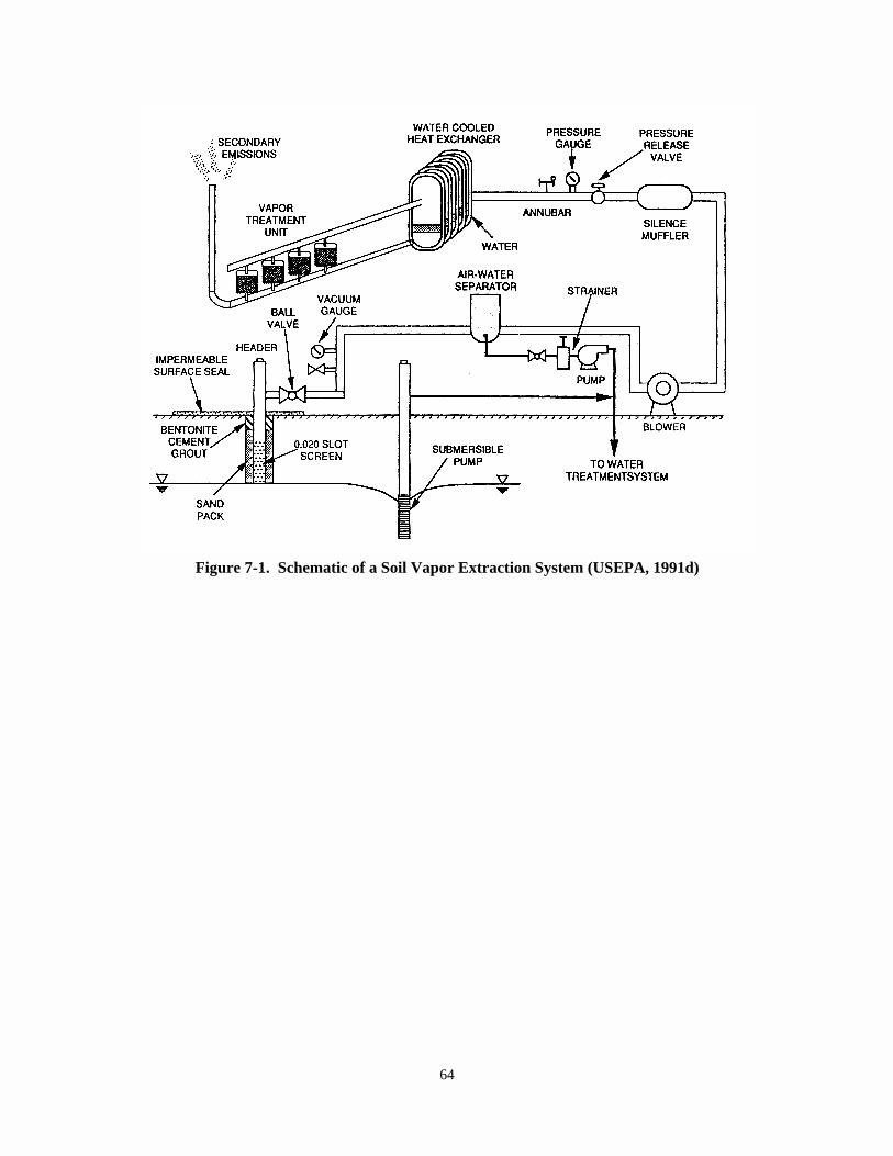
64
Figure 7-1. Schematic of a Soil Vapor Extraction System (USEPA, 1991d)
65
7.2 Vapor Extraction Technology Description
Vapor extraction processes couple vapor extraction wells with blowers or vacuumpumps to create an air-flow field in soil zones permeable to vapor flow. Contaminantsvolatilized within the air-flow field, are swept into the vapor extraction well and areremoved from the soil. Vapor treatment systems, such as catalytic or thermal destructionsystems, activated carbon adsorbers, or biological gas treatment systems may be employedto treat the extracted contaminated air stream (USEPA, 1995a).
Variants of vapor extraction, such as air sparging and thermally enhanced SVE,have been developed to extend the application of vapor extraction technology. Airsparging extends the application of vapor extraction to water-saturated soils byinjecting air under pressure below the water table. Thermally enhanced SVE combinesconventional vapor extraction equipment with a means to elevate the subsurfacetemperature for increasing the volatilization potential of the soil contaminants(USEPA, 1995a).
One advantage of vapor extraction systems is that they generally do not requireaddition of reagents that must be delivered to and subsequently recovered from thecontaminated area (USEPA, 1990).
7.3 Cross-Media Transfer Potential of Vapor Extraction Technologies
(a) General
General cross-media transfer potentials during site preparation, pre-treatment,and post-treatment activities have been addressed in Chapter 2.
(b) Additional Concerns for Vapor Extraction Technologies
& Fugitive vapor emissions through surface soils during operation,especially when injection (air or steam) and fracturingtechnologies are applied.
& Operation of vapor extraction systems may result in the contaminatedsoil moisture becoming condensed and entrained with the systemand/or cause the uptake of contaminated groundwater.
& Surface water can intrude or channel into the contaminated vadosezone altering the anticipated flow of vapors and groundwater.
& Undesirable migration of subsurface contaminant vapors or liquidsinto the soil due to improper design or operation. For instance,improper design of a vapor extraction system can cause unwantedmigration of contaminants from source areas to virgin soils;improper design of an air sparging system can cause unwantedmigration of dissolved phase and vapor phase contaminants to outsidethe remediation area.
66
& During vapor extraction system operation there is potential for VOCemissions through pipes, joints, and valves on thedelivery/discharge side of the vacuum pump.
& Inadequate design and operation of emission control equipment mayalso cause transfer of contaminants to the natural environment.
& Residual contamination in the soil after system operation or beyondthe effective zone of influence of the extraction wells can act as acontinuing source of contamination to groundwater or air.
& Location and design of extraction and injection wells are criticalto ensuring uniform distribution of subsurface air flow and that"dead" zones do not exist within the treatment area.
& With respect to injection techniques, underground sewer and utilityconduits can cause short-circuiting of subsurface air flow, and mayresult in uncontrollable VOC discharges.
& Incomplete cleanup due to low permeability soil strata or units canoccur. Subsurface air flow will follow the path of least resistance;therefore, channeling through more permeable soil zones (e.g.,around natural gravel lenses or fill materials around buildings orutility lines) can result in a partially or wholly ineffectivesystem. Low permeability areas can have high residual contaminantconcentrations while vapor extraction off-gases indicate cleanup iscomplete.
7.4 Best Management Options to Avoid Potential Cross-Media Transfers for VaporExtraction Technologies
General BMPs to prevent potential cross-media transfer of contaminants duringcleanup activities have been addressed in Chapter 2. However, BMP options to controlspecific cross-media transfer of contaminants for vapor extraction technologies areaddressed as follows:
Additional Site Preparation and Staging BMPs:
7 Site investigation and operational plans should identify the presence ofpreferential subsurface air flow pathways and account for all existingunderground utilities (e.g., sewers, electrical conduits).
7 Design and location of extraction and injection wells are critical toensuring proper distribution of subsurface air flow and that "dead" zonesdo not exist within the remediation area.
7 Depth to the ground water table should be identified. Ground watermonitoring wells should be installed to determine presence of LNAPL freeproduct and its recovery strategies. The SVE system design should consider
67
the presence of free product, and the potential applicability of airsparging for combined vadose zone and saturated zone remediation.
7 Extraction wells should not be located near surface water impoundments,underground storm sewers, or drains.
Additional Pre-Treatment Activities: During SVE system construction, includingthe installation of wells and/or, horizontal extraction/injection trenches, thefollowing activities are most commonly undertaken:
® Trench excavation, well drilling, cuttings storage/treatment, drillingmud control and dewatering, air/dust control for dry-air drilling, surfaceprotection for contaminated media.
The following BMP should be used to address these concerns:
7 During dry-air drilling of contaminated soils, VOC emissions should bemonitored and appropriate emission control measures should be used. Forexample, the drilling could be configured so that auger cutting can bedirected through a large-diameter flexible pipe into bins. (See Chapter 3for details on other emission control measures that can applied duringdrilling activities.)
Vapor Extraction Treatment Activities: Prior to SVE system operation, thefollowing activities are generally recommended for better and leak-free operation of thesystem:
7 The number and orientation of extraction wells should be determined.
7 Configuration of injection wells should be determined.
7 Permeability and fracturing options should be evaluated.
7 Wells should be anchored.
7 Surface seals should be installed when there is potential for uncontrolledemissions.
7 The system should be checked for leaks after completion of construction.
7 When VOC emissions or leaks are detected from wellheads, wellhead boxesshould be installed using self-sealing neoprene rubber packers to form aneffective seal between the casing and upper end of the well screen forwellhead protection.
7 Any emissions or discharge from the treatment process should be monitored,and control equipment such as granulated activated carbon, air stripping,and/or biofiltration to treat contaminated water and vapor should beinstalled, if necessary. See Table 3-3 for technologies that can be used to
68
control air emissions. Emission control equipment should be operated inconformance with the allowable levels specified by the regulatoryauthority (EPA or authorized state).
7 Local dewatering should be implemented in areas of open impoundments tocontrol water table and to enhance vadose zone air flow.
7 Pumping systems should be installed, if necessary, for controlling groundwater table.
7 When collecting entrained liquids from vapor extraction technologysystems, these liquids should generally be collected in a tank or alined/contained system. This will prevent the contaminants within theliquids from mixing with the normal surface water runoff from the area, thesurrounding natural watercourse, and surrounding soil. These contaminatedaqueous streams should be treated or disposed of in accordance with theapplicable regulations.
7 Performance monitoring and evaluation should be conducted, includinggeneral system integrity, changes in ground water table, and rate of VOCreduction.
7 Proper safety and care should be exercised to prevent any explosion duringthe recovery and treatment of any light non-aqueous phase liquids (LNAPLs)generated as a free product. When inlet concentrations of the SVE systemexceed 10% of the lower explosion limit (LEL) of the LNAPL (NIOSH, 1990),safety measures such as remote operation of the system, temporary shutdown,or intermittent pumping as specified in USEPA, 1993 should be considered.
Post-Operation Activities: After the extraction wellhead vapor monitoring datareach asymptotic VOC concentrations, soils within the radius of influence of the drawnvacuum may not still be remediated to the cleanup goal. Thus post-treatment monitoringwill be crucial to ensure the control of soil vapor generated from passive venting.
The waste streams generated by in situ SVE are vapor, treatment residuals (e.g.,spent activated carbon), contaminated ground water, and soil tailings from drilling thewells. BMPs for these waste streams are as follows:
7 One option for the vapor stream control/treatment unit is to use abiofiltration process for VOC removal.
7 Contaminated GAC should be carefully removed from the adsorption unit andhandled, stored, and disposed of or recycled in accordance withmanufacturer's recommendations and appropriate state or federalregulations.
7 Contaminated ground water, if extracted along with vapor, may be treatedand discharged on site, if allowed, or collected and treated offsite.
69
7 Proper decommissioning of extraction, injection, and/or monitoring wellsshould be conducted to prevent any future cross-media transfer ofcontaminants after the termination of SVE system operation in accordancewith state and local regulations.
7.5 Waste Characteristics that May Increase the Likelihood of Cross-MediaContamination for Vapor Extraction Technologies
The effectiveness of vapor extraction technologies could be compromised, andundue cross-media contamination may be caused, under certain conditions identified inthis subsection. However, some of these limitations could possibly be overcome bytechnology specific modifications, such as fracturing clay layers to increase airpermeability, injecting hot air to enhance volatility. However, these modificationswould likely increase the design, installation, operation and monitoring costs of thesystem. Please refer to technology-specific references provided at the end of thischapter for additional information about modifications or variations that can be used toenhance the effectiveness of a vapor extraction technology.
� Low permeability soils (i.e., K < 10 cm/sec) (USEPA, 1995a).-5
� The presence of constituents that are not volatile or semi-volatile.
� Sites containing high percentage of silty clay soils and requiring very lowsoil clean-up levels within a short time period.
� Saturated zone soils may be problematic. Air sparging or multi-phase (dualphase) extraction may be considered to treat saturated zone soils andgroundwater.
� Commingled waste may have detrimental effects on the treatment of the vapor(e.g., mercury vapor will significantly affect treatment process used onthe vapor emission control).
7.6 References
1. USEPA. 1995a. Innovative Site Remediation Technology-Vacuum Vapor Extraction,Volume 8, EPA 542/B-94/002, Office of Solid Waste and Emergency Response, April.
2. USEPA. 1995b. SITE Demonstration Bulletin, Subsurface Volatilization andVentilation System, Brown and Root Environmental, EPA/540/MR-94/529, RREL,Cincinnati, January.
3. USEPA. 1995c. SITE Demonstration Bulletin, Unterdruck-Verdempfer-BrunnenTechnology (UVB) Vacuum Vaporizing Well, Roy F. Weston, Inc./IEG TechnologiesCorporation, EPA/540/MR-95/500, RREL, Cincinnati, January.
4. USEPA. 1995d. Review of Mathematical Modeling for Evaluating Soil VaporExtraction Systems, EPA/540/R-95/513, Office of Research and Development,Washington, DC, July.
70
5. USEPA. 1995e. BMP Development Workshop Summary-Vapor Extraction, Office of SolidWaste, Permits and State Programs Division, February.
6. USEPA. 1995f. How to Evaluate Alternative Cleanup Technologies for UndergroundStorage Tank Sites, EPA/510/B-95/007, Office of Solid Waste and EmergencyResponse, May.
7. USEPA. 1994a. Soil Vapor Extraction (SVE) Treatment Technology Resource Guide. EPA/542/B-94/007, Office of Solid Waste and Emergency Response, TechnologyInnovation Office, Washington, DC.
8. USEPA. 1994b. Manual-Alternative Methods for Fluid Delivery and Recovery. EPA/625/R-94/003, Office of Research and Development, Washington, DC, September.
9. USEPA. 1993. Approaches for the Remediation of Federal Facility SitesContaminated with Explosive or Radioactive Wastes, EPA/625/R-93/013, Office ofResearch and Development, Washington, DC, September.
10. USEPA. 1992a. Conducting Field Tests for Evaluation of Soil Vacuum ExtractionApplication, Office of Research and Development, Ada, OK, EPA/540/S-92/004.
11. USEPA. 1992b. A Citizen's Guide to Air Sparging. Technology Fact Sheet. EPA/542/F-92/010, Office of Solid Waste and Emergency Response, TechnologyInnovation Office.
12. USEPA. 1992c. Proceedings of the Symposium on Soil Venting, April 29-May 1, 1991,Houston, Texas, EPA/600/R-92/174, Office of Research and Development,Washington, DC, September.
13. USEPA. 1991a. Guide for Conducting Treatability Studies Under CERCLA: Soil VaporExtraction, Interim Guidance (and Quick Reference Fact Sheet), EPA/540/2-91/019Aand B, Office of Emergency and Remedial Response, September.
14. USEPA. 1991b. Engineering Bulletin-Air Stripping of Aqueous Solutions,EPA/540/2-91/022, Office of Research and Development, Cincinnati, OH, October.
15. USEPA. 1991c. Engineering Bulletin-In Situ Soil Vapor Extraction Treatment,EPA/540/2-91/006, Office of Emergency and Remedial Response, Washington, DC.
16. USEPA. 1991d. Reference Handbook-Soil Vapor Extraction Technology, EPA/540/2-91/003, Office of Research and Development, Washington, DC, February.
17. USEPA. 1990. State of Technology Review-Soil Vapor Extraction Systems,EPA/600/2-89/024, Hazardous Waste Engineering Research Laboratory, August.
18. National Institutes of Occupational Safety and Health (NIOSH). 1990. PocketGuide to Chemical Hazards, US Department of Health and Human Services, June.
71
19. Johnson, P.C., M.W. Kemblowski, J.D. Colthart, D.L. Buyers, and C.C. Stanley.1990. A Practical Approach to the Design, Operation, and Monitoring of In-SituSoil Venting Systems, Shell Development/Shell Oil Company, Spring.
20. Baehr, Arthur, George Hoag, and Michael Marley. 1988. Removing VolatileContaminants from the Unsaturated Zone by Inducing Advective Air-Phase Transport,June 20.
21. USEPA. 1989a. Soil Vapor Extraction VOC Control Technology Assessment, EPA-450/4-89/017, Office of Air Quality Planning and Standards, September.
22. USEPA. 1989b. Technology Evaluation Report: SITE Program Demonstration Test --Terra Vac In Situ Vacuum Extraction System, Groveland, Massachusetts, Volume 1,EPA/540/5-89/003a, April.
23. USEPA. 1989c. Applications Analysis Report: Terra Vac In Situ Vacuum ExtractionSystem, EPA/540/A5-89/003, Office of Research and Development, July.
72
Bioremediation is a treatment technology that uses biodegradation of organiccontaminants through stimulation of indigenous microbial populations by providingcertain amendments, such as adding oxygen or limiting nutrients, or adding exoticmicrobial species. It uses naturally occurring or externally-applied microorganismsto degrade and transform hazardous organic constituents into compounds of reducedtoxicity and/or availability. Specific technologies fall into two broad categories: (1) Ex situ technologies (e.g., slurry phase, land treatment, solid phase,composting), and (2) In situ technologies (USEPA, 1991c). Active remediation caninclude addition of such amendments as nutrients or oxygen and passive remediationutilizes natural attenuation to adequately characterize, model and monitor the siteto evidence natural attenuation and protection of potential receptors.
8.0 Chapter Eight: BMPs for BIOREMEDIATION
This chapter focuses on the generally accepted best management practices (BMPs) tominimize cross-media transfer of contaminants during remedial actions or correctivemeasure implementations when using bioremediation technologies to treat soils or solidmedia. BMPs are meant only to provide guidance and general recommendations on theoperational practices of selected technologies. BMPs are not meant to direct or dictatethe selection of appropriate technologies.
8.1 Definition and Scope of Bioremediation (for BMPs)
Many different types of bioremediation technologies are currently being used forsoils treatment, and many more innovative approaches involving bioremediation are beingdeveloped. Considering their similarity in cross-media transfer potentials, thefollowing treatment technologies and processes are listed as a few examples ofbioremediation (for the purpose of BMPs):
& Natural Attenuation & Bioremediation of Metals (Changing& Biodegradation the Valence)& Aerobic/Anaerobic & Binding of Metals
Biodegradation & Plant Root Uptake& Biopiles (Phytoremediation)& Composting & Fungi Inoculation Process & Land Treatment & Slurry Phase Bioremediation& Bioreactors & Solid Phase Bioremediation& Bioscrubbers & Bioventing (addressed in Chapter.& Dehalogenation 7, BMPs for Vapor Extraction)& Methanotrophic Process & Bio Wall for Plume Decontamination
(In Situ)
The scope of BMPs for bioremediation technologies is not limited to the abovelisted technologies. Any treatment technology that meet the key features ofbioremediation treatment, as described below, should generally be considered asbioremediation treatments for the purpose of BMPs.
A typical schematic for solid phase bioremediation is shown on Figure 8-1.
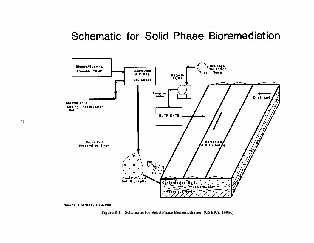
73
Figure 8-1. Schematic for Solid Phase Bioremediation (USEPA, 1995c)
74
8.1.1 Key Features of Bioremediation for the Purpose of BMPs
& Most bioremediation soils treatment technologies generally destroycontaminants in the soil matrix.
& Generally these treatment technologies are designed to reducetoxicity either by destruction or by transforming toxic organiccompounds to less toxic compounds.
& Indigenous micro-organisms, including bacteria and fungi are mostcommonly used. In some cases, wastes may be inoculated with specificbacteria or fungi known to biodegrade the contaminants of concern. Plants may also be used to enhance biodegradation and stabilize thesoil.
& May require the addition of nutrients or electron acceptors (such ashydrogen peroxide or ozone) to enhance growth and reproduction ofindigenous organisms.
& Field applications of bioremediation may involve:
— Excavation — Soil handling— Storage of contaminated soil piles— Mixing of contaminated soils— Aeration of contaminated soils— Injection of fluid— Extraction of fluid— Introduction of nutrients and substrates
Several of the above field applications may not necessarily be viewed separatelyand may need to be used together.
8.2 Bioremediation Technology Description
Bioremediation involves the use of microorganisms to chemically degrade organiccontaminants. Aerobic processes use organisms that require oxygen to be able to degradecontaminants. In some cases, additional nutrients such as nitrogen and phosphorous arealso needed to encourage the growth of biodegrading organisms. A biomass of organisms --which may include entrained constituents of the waste, partially degraded constituents,and intermediate biodegradation products -- is formed during the treatment process(USEPA, 1990d).
Although bioremediation is applied in many different ways, descriptions oftypical solid-phase bioremediation, composting, bioventing, and traditional in situbiodegradation are provided here. Solid-phase bioremediation treatment can be conductedin lined land treatment units or in composting piles. A lined land treatment unitconsists of a prepared bed reactor with a leachate collection system and irrigation andnutrient delivery systems. The unit also may contain air emission control equipment.
75
Figure 8-1 illustrates treatment by solid phase bioremediation. The soil is placed onland lined with an impervious layer, such as soil, clay, or a synthetic liner.
Solid-phase biological treatment of soil can also be performed in compostingpiles. Figure 8-2 illustrates a typical composting treatment process, including acompost pile, wood chip cover and base, ventilation pipes, and leachate collectionsystem. In composting, the soil is mixed with fertilizer, water, and a bulking agent suchas wood chips or sand, and placed in piles from 3 to 6 feet high (USATHAMA, 1988). Thebulking agent helps to mix and aerate the material. Oxygen can be supplied to the pile byintroducing air (using a blower and series of pipes) below the pile, or byturning/cultivating the pile. The addition of nutrients, such as manure or molasses, tothe soil mixture can increase exothermic biodegradation reaction rates and therebyincrease the operating temperature of the composting pile. The introduction of air canalso help to control the temperature of the system. The addition of bulking agents willreduce the concentration of organic compounds in the soil; hence, the concentration oforganics in the untreated soil must be sufficiently high to initiate and maintain thecomposting process.
The in situ biodegradation process is generally used in conjunction with groundwater pumping and soil flushing systems to circulate nutrients and oxygen through acontaminated aquifer and associated soil (Freeman and Harris, 1995). The process usuallyinvolves introducing aerated nutrient-enriched water into the contaminated zone througha series of infiltration galleries and injection wells and recovering the waterdowngradient. The recovered water can then be treated, if necessary, and reintroduced tothe soil on site, where allowed by applicable regulations. The in situ biodegradationsystem may also include aboveground treatment and conditioning of the infiltration waterwith nutrients and an oxygen (or other electron acceptor) source (USEPA, 1994d).
Bioventing uses relatively low-flow soil aeration techniques to enhance thebiodegradation of soils contaminated with organic contaminants. Although bioventing ispredominantly used to treat unsaturated soils, applications involving the remediation ofsaturated soils and groundwater (augmented by air sparging) are becoming more common.Generally a vacuum extraction, air injection, or combination of vacuum extraction and airinjection system is employed (Freeman and Harris, 1995). An air pump, one or more airinjection or vacuum extraction probes, and emissions monitors at the ground surface arecommonly used.
Ex situ processes also include landfarming, which involves spreading contaminatedsoils over a large area. Bioremediation may also be conducted in a bioreactor, in whichcontaminated soil or sludge is slurried with water in a mixing tank or lagoon. Bioremediation systems require that the contaminated soil or sludge be sufficiently andhomogeneously mixed to ensure optimum contact with the seed organisms (USEPA, 1990d).
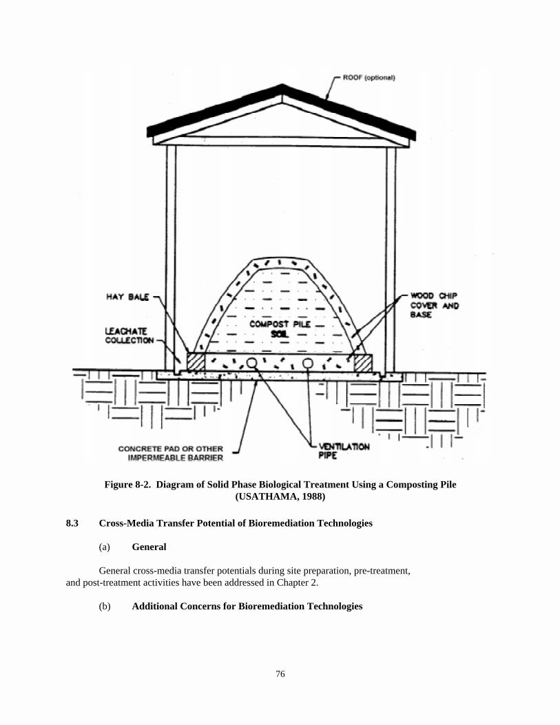
76
Figure 8-2. Diagram of Solid Phase Biological Treatment Using a Composting Pile(USATHAMA, 1988)
8.3 Cross-Media Transfer Potential of Bioremediation Technologies
(a) General
General cross-media transfer potentials during site preparation, pre-treatment,and post-treatment activities have been addressed in Chapter 2.
(b) Additional Concerns for Bioremediation Technologies
77
& Release of VOCs to air or water can occur during sampling andanalysis conducted as part of the implementation of thebioremediation treatment.
& Some in situ bioremediation processes may generate soil gasemissions in excess of background levels.
& SVOC/VOC emissions may be released from leaks in pipes, joints,valves, and uncovered conveyor systems used in some bioremediationtechnology operations.
& Nutrients that are applied as a part of a bioremediation treatment,such as landfarming, may be carried through run off to surface wateror leach to groundwater if the treatment is improperly designedand/or implemented.
& Very high wind speeds may be of particular concern due to thepotential for emissions during active composting or otheroperations where soils may not be covered or enclosed.
8.4 Best Management Options to Avoid Potential Cross-Media Transfers forBioremediation Technologies
General BMPs to prevent potential cross-media transfer of contaminants duringpre-treatment and post-treatment activities have been addressed in Chapter 2. Onlytechnology-specific treatment activities and possible BMP options to control cross-media transfer of contaminants during these activities are furnished below.
During the bioremediation treatment process the following activities are mostcommonly undertaken:
® For ex situ bioremediation, excavation, storage, mixing, and otherpreparatory steps are undertaken prior to feeding contaminated soilstockpile to the bioreactor or treatment bed comprised of lined landtreatment units. In case of composting piles, the soil is mixed withfertilizer, water, and a bulking agent, such as wood chips or sand, andplaced in piles from 3 to 6 feet high (USATHAMA, 1988). In somebioremediation application nutrients and substrates are introduced intothe treatment bed. Drainage from the treatment bed is generally collectedin a sump area and recycled back to the treatment bed.
® In the case of in situ bioremediation, electron acceptors (e.g., oxygen andnitrate), nutrients, and other amendments may be introduced into the soiland ground water to encourage the growth of indigenous microorganismscapable of degrading the contaminants. The principal activitiessurrounding in situ bioremediation involves: (a) boundary determinationof the treatment zone in both horizontal extent and depth, (b) injection ofnutrients and other amendments, and (c) periodic monitoring ofconcentration levels of contaminant in the soil or solid media. Bioventing
78
and other in situ biodegradation systems generally use infiltrationgalleries or injection wells to deliver required amendments to thesubsurface.
The following BMPs may be used, when necessary and appropriate, to prevent cross-media transfer of contaminants for the above activities:
7 Biotreatments occasionally produce unpleasant odors. Effective odorcontrol measures such as vapor collection systems, or other methods asdetailed in Chapter 3, should be used if necessary.
7 Surface treatment structures such as biopiles or compost piles should notbe constructed and maintained in areas that are prone to encounter highwinds. Wind can damage plastic or tarp covers, remove surface materialssuch as straw or mulch that provide insulation and protection, and carrydust and nutrients away from the treatment area, thereby causing cross-media contamination. In addition, removal of surface protection increasesthe likelihood of infiltration of rainfall, which increases the likelihoodof the production of leachate.
7 For technologies such as composting, landfarming, and other surfacetreatments, runoff and leachate should be collected and tested regularly toensure that nutrient levels do not exceed regulatory standards for surfacewater and ground water. In particular, nutrients such as phosphate andnitrate may be of concern and may need to be monitored carefully throughoutthe treatment process.
7 Any covers or liners that are used in surface treatment structures, such asbiopiles or compost piles, should be periodically examined to ensure thatthey have not been torn or otherwise damaged. Any damaged covers or linersshould be repaired or replaced upon discovery.
8.5 Waste Characteristics that May Increase the Likelihood of Cross-MediaContamination for Bioremediation Technologies
The effectiveness of bioremediation technologies could be compromised and unduecross-media contamination may be caused under certain conditions identified in thissubsection. Please refer to technology-specific references provided at the end of thischapter for additional information about modifications or variations that can be used toenhance the effectiveness of a bioremediation technology.
� All bioremediation applications are dependent upon site specificconditions and the environment or matrix in which the contamination isfound. The environment and matrix situation should generally be analyzedprior to choosing the treatment method. For example, some microbes needspecific properties in order to be effective (e.g., high tolerance for acidconditions, saline conditions), and some compounds need to be treated undercertain conditions (e.g., aerobically, anaerobically).
79
� In situ bioremediation applications requiring circulation of fluids shouldbe avoided in case of tight clay or heterogeneous subsurface environmentswhere oxygen (or other electron acceptor) transfer limitations exist. Thislimitation could possibly be overcome by modification of the site ortechnology, but it would result in a more costly cleanup.
� Because it generally requires some time to be effective, in situbioremediation should not be considered in the case of emergencyremoval/remedy - "fast cleanup". However, ex situ treatment, e.g., in areactor, may be appropriate.
� Concentration of the contaminant above the toxicity tolerance level of themicroorganisms (which varies with the bioavailability of the compound)will make biodegradation ineffective.
� Concentrations of contaminants required to sustain microbial populationmay be above the regulatory limit. Conversely, sometimes the microbialpopulation cannot survive because of the concentrations of contaminantsbeing too low to sustain it. A treatment train or other alternatives shouldbe considered under these circumstances.
� Technologies to treat some metals in heterogeneous mixtures, such as leadand mercury, should be used very carefully (e.g., iron oxide, hexavalentchromium, mercury).
Additional BMPs for Residuals Management - Generally, there are few residuals totreat with bioremediation technologies. The exception is the bioreactor, which maygenerate carbon dioxide, water or other off-gases. Bioreactors should be designed withmonitoring equipment to ensure that off-gases do not produce air emissions at levelshigher than the state or federal regulatory limit.
7 Management of treated soils, sediments, and geological material: Frequently bioremediation does not bring the concentration of individualhazardous components in soil, subsurface material, or sediment to currentconcentration-based standards. Depending on the bioavailability of thoseindividual hazardous components to the human population or plants andwildlife, the hazard may or may not be controlled in the treated material. Properly remediated geological material should not release or emithazardous constituents to soil, air or ground water in contact with theremediated material. Nevertheless, as with any technology that is used totreat hazardous wastes, engineering or institutional controls should be inplace to prevent direct contact with the treated material by the humanpopulation or critical environmental receptors. If effective engineeringor institutional controls are not in place to prevent exposure, a riskanalysis of direct exposure should indicate that the level of risk isacceptable.
8.6 References
80
1. Freeman, Harry M. and Eugene F. Harris. 1995. Hazardous Waste Remediation: Innovative Treatment Technologies, Technomic Publishing Co., Inc., Lancaster,PA.
2. USEPA. 1995a. Innovative Site Remediation Technology-Bioremediation, Volume I, EPA 542/B-94/006, Office of Solid Waste and Emergency Response, June.
3. USEPA. 1995b. In Situ Remediation Technology Status Report: Treatment Walls, EPA/542/K-94/004, Office of Solid Waste and Emergency Response.
4. USEPA. 1995c. Contaminants and Remedial Options at Solvent-Contaminated Site, EPA/600/R-94/203, Office of Research and Development.
5. USEPA. 1994a. Emerging Technology Bulletin, Institute of Gas Technology, FluidExtraction-Biological Degradation Process, EPA/540/F-94/501, March.
6. USEPA. 1994b. Engineering Bulletin-In Situ Biodegradation Treatment, EPA/540/S-94/502, Office of Research and Development, Cincinnati, OH, April.
7. USEPA. 1994c. BMP Development Workshop Summary-Bioremediation, November.
8. USEPA. 1994d. Remediation Technologies Screening Matrix and Reference Guide,EPA/542/B-94/013, October.
9. National Academy of Sciences. 1993. In Situ Bioremediation-When Does It Work? National Academy Press.
10. USEPA. 1993a. Guide for Conducting Treatability Studies Under CERCLA,Biodegradation Remedy Selection, Interim Guidance (and Quick Reference FactSheet), EPA/540/R-93/519a and b, Office of Solid Waste and Emergency Response,August.
11. USEPA. 1993b. Bioremediation Resource Guide, EPA/542/B-93/004, Office of SolidWaste and Emergency Response, Technology Innovation Office, Washington, DC.
12. USEPA. 1992a. Seminar Publication: Organic Air Emissions from Waste ManagementFacilities, EPA/625/R-92/003, Office of Air Quality Planning and Standards,August.
13. USEPA. 1992b. Engineering Bulletin-Rotating Biological Contactors, EPA/540/S-92/007, Office of Research and Development, Cincinnati, OH, October.
14. USEPA. 1992c. Engineering Bulletin-Slurry Walls. EPA/540/S-92/008, Office ofResearch and Development, Cincinnati, OH, October.
15. USEPA. 1992d. A Citizen's Guide to Bioventing-Technology Fact Sheet, EPA/542/F-92/008, Office of Solid Waste and Emergency Response, Technology InnovationOffice.
81
16. USEPA. 1991a. Guide for Conducting Treatability Studies Under CERCLA: AerobicBiodegradation Remedy Screening-Interim Guidance, EPA/540/2-91/013A, Office ofResearch and Development, Washington, DC.
17. USEPA. 1991b. Guide for Conducting Treatability Studies Under CERCLA: AerobicBiodegradation Remedy Screening-Quick Reference Fact Sheet, EPA/540/2-91/013B,Office of Emergency and Remedial Response, Hazardous Site Control Division.
18. USEPA. 1991c. Innovative Treatment Technologies: Overview and Guide toInformation Sources, EPA/540/9-91/002, Office of Solid Waste and EmergencyResponse, October.
19. Pitter, Pavel and Jan Chudoba. 1990. Biodegradability of Organic Substances inthe Aquatic Environment, CRC Press.
20. USEPA. 1990a. Engineering Bulletin-Slurry Biodegradation. EPA/540/2-90/016. Office of Research and Development, Cincinnati, OH, September.
21. USEPA. 1990b. Engineering Bulletin-In Situ Biodegradation Treatment, EPA/540/S-94/502, Office of Research and Development, December.
22. USEPA. 1990c. Summary of Treatment Technology Effectiveness for ContaminatedSoil, EPA/540/2-89/053, Office of Emergency and Remedial Response, Washington,DC.
23. USEPA. 1990d. Handbook on In Situ Treatment of Hazardous Waste - ContaminatedSoils, EPA/540/2-90/002, Office of Research and Development.
24. Ornston, L. Nicholas, Albert Balows, and Paul Baumann. 1988. Annual Review ofMicrobiology, Volume 42, Annual Reviews, Inc.
25. Ross, Derek. 1988. Application of Biological Processes to the Clean Up ofHazardous Wastes. Environmental Resources Limited.
26. U.S. Army Toxic and Hazardous Materials Agency (USATHAMA) (now U.S. ArmyEnvironmental Center (USAEC)). 1988. Field Demonstration -- Composting ofExplosives-Contaminated Sediment at the Louisiana Army Ammunition Plant (LAAP),September.
27. USEPA. 1986. Microbial Decomposition of Chlorinated Aromatic Compounds. EPA/600/2-86/090, Office of Research and Development, September.
28. Gibson, David T. 1984. Microbial Degradation of Organic Compounds, MarcelDekker, Inc.
29. Chakrabarty, A.M. 1982. Biodegradation and Detoxification of EnvironmentalPollutants, CRC Press.
82
30. Pramer, David and Richard Bartha. 1972. Preparation and Processing of SoilSamples for Biodegradation Studies, Environmental Letters, 2(4), pp. 217-224.
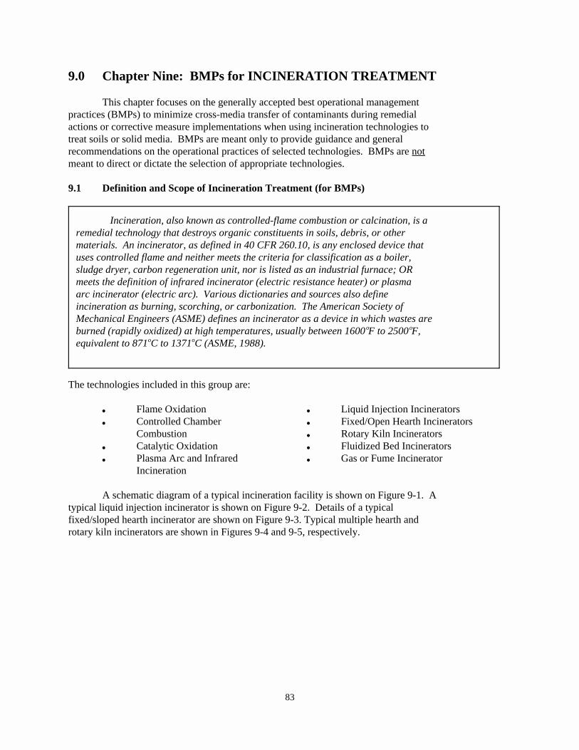
83
Incineration, also known as controlled-flame combustion or calcination, is aremedial technology that destroys organic constituents in soils, debris, or othermaterials. An incinerator, as defined in 40 CFR 260.10, is any enclosed device thatuses controlled flame and neither meets the criteria for classification as a boiler,sludge dryer, carbon regeneration unit, nor is listed as an industrial furnace; ORmeets the definition of infrared incinerator (electric resistance heater) or plasmaarc incinerator (electric arc). Various dictionaries and sources also defineincineration as burning, scorching, or carbonization. The American Society ofMechanical Engineers (ASME) defines an incinerator as a device in which wastes areburned (rapidly oxidized) at high temperatures, usually between 1600 F to 2500 F,o o
equivalent to 871 C to 1371 C (ASME, 1988).o o
9.0 Chapter Nine: BMPs for INCINERATION TREATMENT
This chapter focuses on the generally accepted best operational managementpractices (BMPs) to minimize cross-media transfer of contaminants during remedialactions or corrective measure implementations when using incineration technologies totreat soils or solid media. BMPs are meant only to provide guidance and generalrecommendations on the operational practices of selected technologies. BMPs are notmeant to direct or dictate the selection of appropriate technologies.
9.1 Definition and Scope of Incineration Treatment (for BMPs)
The technologies included in this group are:
& Flame Oxidation & Liquid Injection Incinerators& Controlled Chamber & Fixed/Open Hearth Incinerators
Combustion & Rotary Kiln Incinerators& Catalytic Oxidation & Fluidized Bed Incinerators& Plasma Arc and Infrared & Gas or Fume Incinerator
Incineration
A schematic diagram of a typical incineration facility is shown on Figure 9-1. Atypical liquid injection incinerator is shown on Figure 9-2. Details of a typicalfixed/sloped hearth incinerator are shown on Figure 9-3. Typical multiple hearth androtary kiln incinerators are shown in Figures 9-4 and 9-5, respectively.
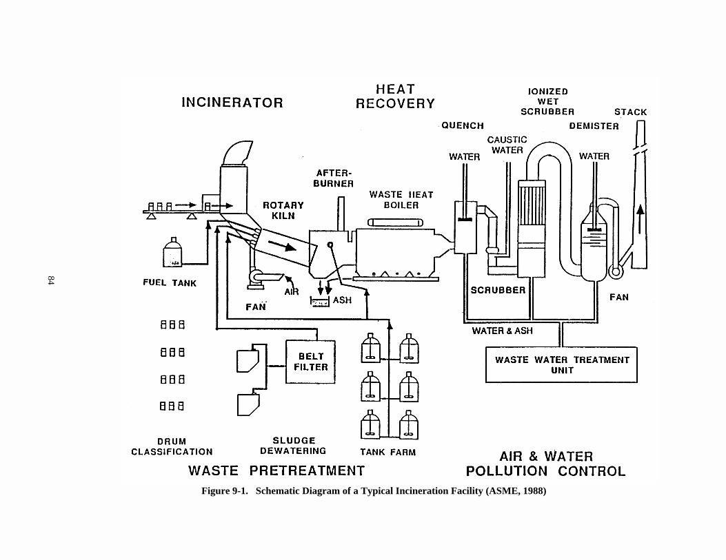
84
Figure 9-1. Schematic Diagram of a Typical Incineration Facility (ASME, 1988)
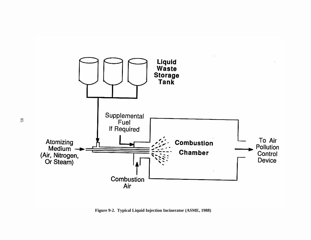
85
Figure 9-2. Typical Liquid Injection Incinerator (ASME, 1988)
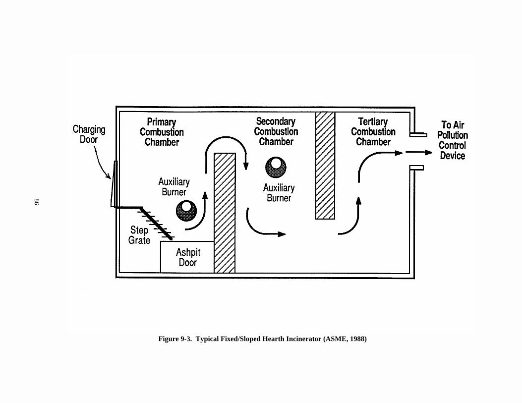
86
Figure 9-3. Typical Fixed/Sloped Hearth Incinerator (ASME, 1988)
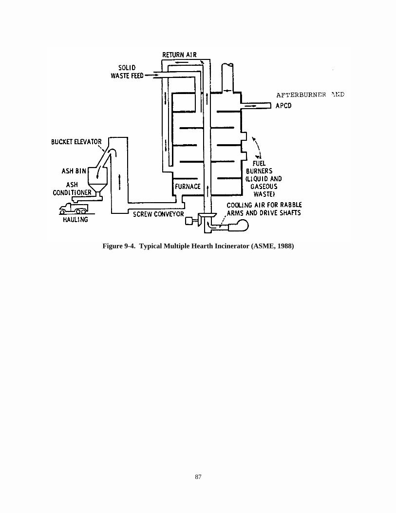
87
Figure 9-4. Typical Multiple Hearth Incinerator (ASME, 1988)
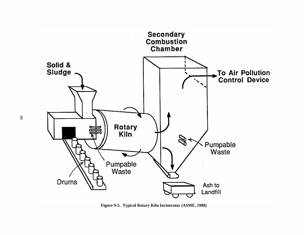
88
Figure 9-5. Typical Rotary Kiln Incinerator (ASME, 1988)
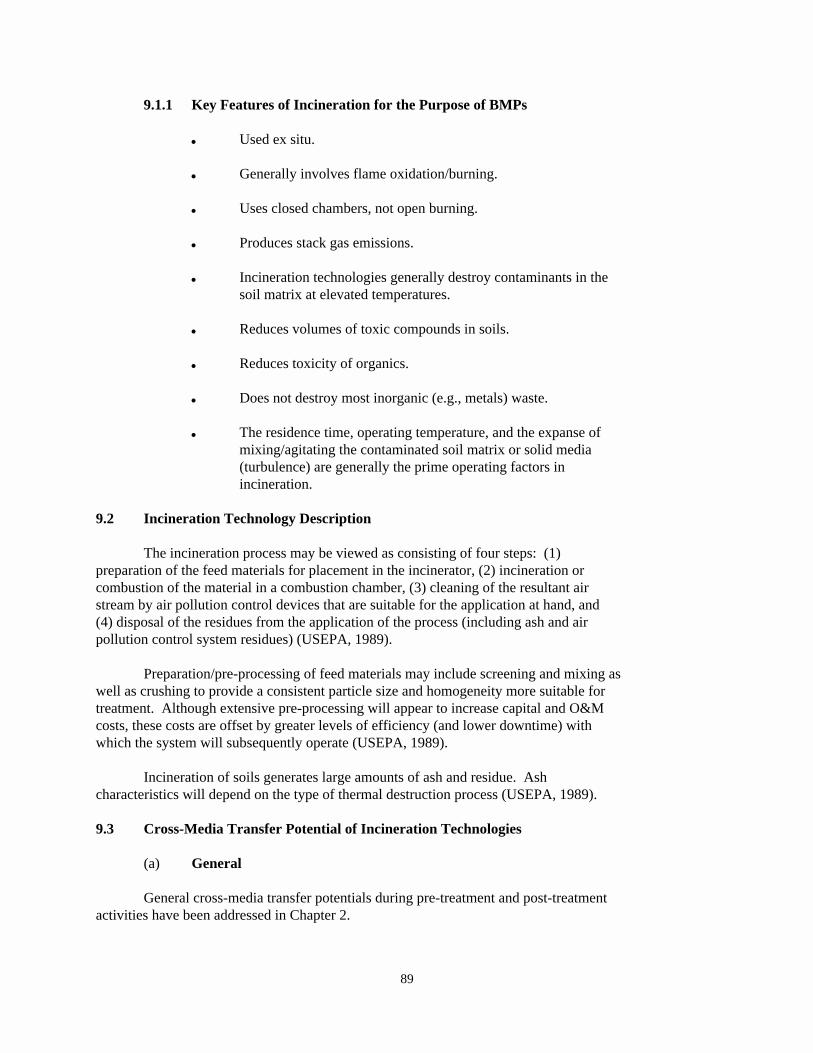
89
9.1.1 Key Features of Incineration for the Purpose of BMPs
& Used ex situ.
& Generally involves flame oxidation/burning.
& Uses closed chambers, not open burning.
& Produces stack gas emissions.
& Incineration technologies generally destroy contaminants in thesoil matrix at elevated temperatures.
& Reduces volumes of toxic compounds in soils.
& Reduces toxicity of organics.
& Does not destroy most inorganic (e.g., metals) waste.
& The residence time, operating temperature, and the expanse ofmixing/agitating the contaminated soil matrix or solid media(turbulence) are generally the prime operating factors inincineration.
9.2 Incineration Technology Description
The incineration process may be viewed as consisting of four steps: (1)preparation of the feed materials for placement in the incinerator, (2) incineration orcombustion of the material in a combustion chamber, (3) cleaning of the resultant airstream by air pollution control devices that are suitable for the application at hand, and(4) disposal of the residues from the application of the process (including ash and airpollution control system residues) (USEPA, 1989).
Preparation/pre-processing of feed materials may include screening and mixing aswell as crushing to provide a consistent particle size and homogeneity more suitable fortreatment. Although extensive pre-processing will appear to increase capital and O&Mcosts, these costs are offset by greater levels of efficiency (and lower downtime) withwhich the system will subsequently operate (USEPA, 1989).
Incineration of soils generates large amounts of ash and residue. Ashcharacteristics will depend on the type of thermal destruction process (USEPA, 1989).
9.3 Cross-Media Transfer Potential of Incineration Technologies
(a) General
General cross-media transfer potentials during pre-treatment and post-treatmentactivities have been addressed in Chapter 2.
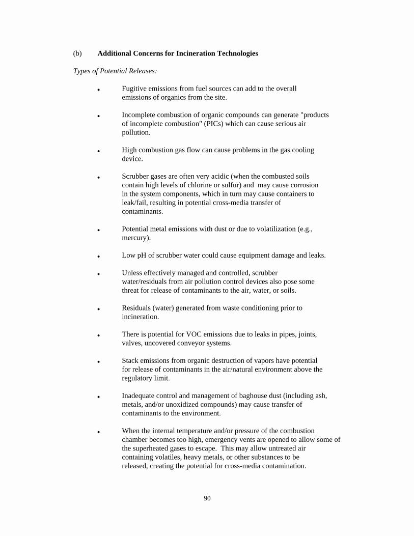
90
(b) Additional Concerns for Incineration Technologies
Types of Potential Releases:
& Fugitive emissions from fuel sources can add to the overallemissions of organics from the site.
& Incomplete combustion of organic compounds can generate "productsof incomplete combustion" (PICs) which can cause serious airpollution.
& High combustion gas flow can cause problems in the gas coolingdevice.
& Scrubber gases are often very acidic (when the combusted soilscontain high levels of chlorine or sulfur) and may cause corrosionin the system components, which in turn may cause containers toleak/fail, resulting in potential cross-media transfer ofcontaminants.
& Potential metal emissions with dust or due to volatilization (e.g.,mercury).
& Low pH of scrubber water could cause equipment damage and leaks.
& Unless effectively managed and controlled, scrubberwater/residuals from air pollution control devices also pose somethreat for release of contaminants to the air, water, or soils.
& Residuals (water) generated from waste conditioning prior toincineration.
& There is potential for VOC emissions due to leaks in pipes, joints,valves, uncovered conveyor systems.
& Stack emissions from organic destruction of vapors have potentialfor release of contaminants in the air/natural environment above theregulatory limit.
& Inadequate control and management of baghouse dust (including ash,metals, and/or unoxidized compounds) may cause transfer ofcontaminants to the environment.
& When the internal temperature and/or pressure of the combustionchamber becomes too high, emergency vents are opened to allow some ofthe superheated gases to escape. This may allow untreated aircontaining volatiles, heavy metals, or other substances to bereleased, creating the potential for cross-media contamination.
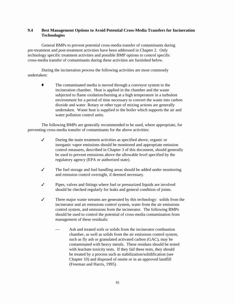
91
9.4 Best Management Options to Avoid Potential Cross-Media Transfers for IncinerationTechnologies
General BMPs to prevent potential cross-media transfer of contaminants duringpre-treatment and post-treatment activities have been addressed in Chapter 2. Onlytechnology specific treatment activities and possible BMP options to control specificcross-media transfer of contaminants during these activities are furnished below.
During the incineration process the following activities are most commonlyundertaken:
® The contaminated media is moved through a conveyor system to theincineration chamber. Heat is applied in the chamber and the wastesubjected to flame oxidation/burning at a high temperature in a turbulentenvironment for a period of time necessary to convert the waste into carbondioxide and water. Rotary or other type of mixing actions are generallyundertaken. Waste heat is supplied to the boiler which supports the air andwater pollution control units.
The following BMPs are generally recommended to be used, where appropriate, forpreventing cross-media transfer of contaminants for the above activities:
7 During the main treatment activities as specified above, organic orinorganic vapor emissions should be monitored and appropriate emissioncontrol measures, described in Chapter 3 of this document, should generallybe used to prevent emissions above the allowable level specified by theregulatory agency (EPA or authorized state).
7 The fuel storage and fuel handling areas should be added under monitoringand emission control oversight, if deemed necessary.
7 Pipes, valves and fittings where fuel or pressurized liquids are involvedshould be checked regularly for leaks and general condition of joints.
7 Three major waste streams are generated by this technology: solids from theincinerator and air emissions control system, water from the air emissionscontrol system, and emissions from the incinerator. The following BMPsshould be used to control the potential of cross-media contamination frommanagement of these residuals:
— Ash and treated soils or solids from the incinerator combustionchamber, as well as solids from the air emissions control system,such as fly ash or granulated activated carbon (GAC), may becontaminated with heavy metals. These residues should be testedwith leachate toxicity tests. If they fail these tests, they shouldbe treated by a process such as stabilization/solidification (seeChapter 10) and disposed of onsite or in an approved landfill(Freeman and Harris, 1995).
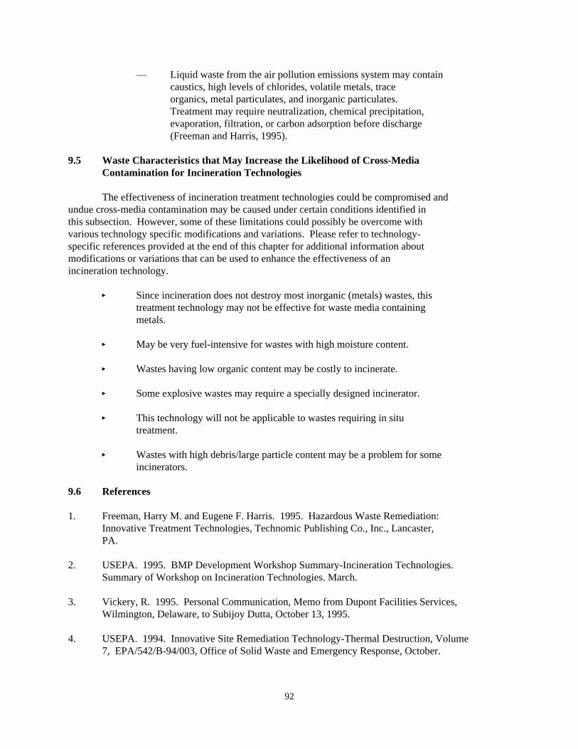
92
— Liquid waste from the air pollution emissions system may containcaustics, high levels of chlorides, volatile metals, traceorganics, metal particulates, and inorganic particulates. Treatment may require neutralization, chemical precipitation,evaporation, filtration, or carbon adsorption before discharge(Freeman and Harris, 1995).
9.5 Waste Characteristics that May Increase the Likelihood of Cross-MediaContamination for Incineration Technologies
The effectiveness of incineration treatment technologies could be compromised andundue cross-media contamination may be caused under certain conditions identified inthis subsection. However, some of these limitations could possibly be overcome withvarious technology specific modifications and variations. Please refer to technology-specific references provided at the end of this chapter for additional information aboutmodifications or variations that can be used to enhance the effectiveness of anincineration technology.
� Since incineration does not destroy most inorganic (metals) wastes, thistreatment technology may not be effective for waste media containingmetals.
� May be very fuel-intensive for wastes with high moisture content.
� Wastes having low organic content may be costly to incinerate.
� Some explosive wastes may require a specially designed incinerator.
� This technology will not be applicable to wastes requiring in situtreatment.
� Wastes with high debris/large particle content may be a problem for someincinerators.
9.6 References
1. Freeman, Harry M. and Eugene F. Harris. 1995. Hazardous Waste Remediation: Innovative Treatment Technologies, Technomic Publishing Co., Inc., Lancaster,PA.
2. USEPA. 1995. BMP Development Workshop Summary-Incineration Technologies. Summary of Workshop on Incineration Technologies. March.
3. Vickery, R. 1995. Personal Communication, Memo from Dupont Facilities Services,Wilmington, Delaware, to Subijoy Dutta, October 13, 1995.
4. USEPA. 1994. Innovative Site Remediation Technology-Thermal Destruction, Volume7, EPA/542/B-94/003, Office of Solid Waste and Emergency Response, October.
93
5. USEPA. 1993. Approaches for the Remediation of Federal Facility SitesContaminated with Explosive or Radioactive Wastes, EPA/625/R-93/013, Office ofResearch and Development, Washington, DC, September.
6. USEPA. 1990. Engineering Bulletin-Mobile/Transportable Incineration Treatment, EPA/540/2-90/014, Office of Research and Development, Cincinnati, OH, September.
7. USEPA. 1989. Seminar Publication Corrective Action Technologies andApplications, EPA/625/4-89/020, pages 41-47.
8. ASME. 1988. Hazardous Waste Incineration, A Resource Document, American Societyof Mechanical Engineers, New York, NY, January.
9. USEPA. 1988. Hazardous Waste Incineration: Questions and Answers, EPA/SW-88-018, Office of Solid Waste, Washington, DC.
94
10.0 Chapter Ten: BMPs for OTHER PHYSICAL/CHEMICAL TREATMENTS
This chapter focuses on the generally accepted best management practices (BMPs) tominimize cross-media transfer of contaminants during remedial actions or correctivemeasure implementations when using "other physical/chemical treatment technologies" totreat soils or solid media. BMPs are meant only to provide guidance and generalrecommendations on the operational practices of selected technologies. BMPs are notmeant to direct or dictate the selection of appropriate technologies.
The category of "other physical/chemical treatment" includes all technologiesthat are not within the purview of the previous six chapters. BMPs for most of the in situtreatment technologies are addressed in this chapter.
10.1 Definition and Scope of Other Physical and Chemical Treatment (for BMPs)
The classification of "other physical and chemical" treatment envelops a varietyof novel treatment technologies that are currently being applied to the treatment ofcontaminated soils and solid media. These technologies can be applied independently orin conjunction with other methods to enhance removal and/or stabilization of thecontaminants.
The following technologies are listed as a few examples of "other" treatmenttechnologies (for the purpose of BMPs):
& In Situ Radio Frequency & Fracturing(RF) Heating & Solvent Extraction
& In Situ Vitrification & Phyto Uptake (Wetlands)& In Situ IR Heating & Gasification/Pyrolysis& Chemical Based & Debris Washing
Stabilization & Grouting& In Situ Redox Control & Dechlorination& In Situ Soil Flushing
The scope of BMPs for other physical/chemical treatment is not limited to the abovelisted technologies. Although a number of treatment technologies are listed within thistechnology category, details of only radio frequency (RF) heating, in situvitrification, in situ soil flushing, solidification/stabilization (S/S) and off-sitedisposal have been addressed in this document because of their broad applicability as itpertains to issues related to cross-media transfer of contaminants.
BMPs presented in this chapter and previous chapters of this guidance can beapplied when appropriate, especially to these physical/chemical technologies that arenot specifically addressed here. BMPs for in situ radio frequency heating, which ispresented in this chapter, can be applied to in situ IR heating and in situ redox control. For other technologies for which BMPs are not specifically provided in this chapter, thelist below provides reference to the chapter containing BMPs that can be applied to thetechnology.
& Phyto Uptake and Dechlorination -- Chapter 2
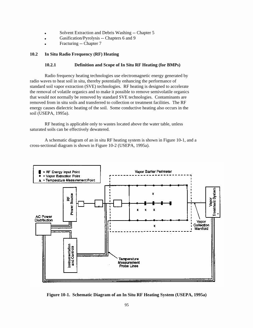
95
Figure 10-1. Schematic Diagram of an In Situ RF Heating System (USEPA, 1995a)
& Solvent Extraction and Debris Washing -- Chapter 5& Gasification/Pyrolysis -- Chapters 6 and 9& Fracturing -- Chapter 7
10.2 In Situ Radio Frequency (RF) Heating
10.2.1 Definition and Scope of In Situ RF Heating (for BMPs)
Radio frequency heating technologies use electromagnetic energy generated byradio waves to heat soil in situ, thereby potentially enhancing the performance ofstandard soil vapor extraction (SVE) technologies. RF heating is designed to acceleratethe removal of volatile organics and to make it possible to remove semivolatile organicsthat would not normally be removed by standard SVE technologies. Contaminants areremoved from in situ soils and transferred to collection or treatment facilities. The RFenergy causes dielectric heating of the soil. Some conductive heating also occurs in thesoil (USEPA, 1995a).
RF heating is applicable only to wastes located above the water table, unlesssaturated soils can be effectively dewatered.
A schematic diagram of an in situ RF heating system is shown in Figure 10-1, and across-sectional diagram is shown in Figure 10-2 (USEPA, 1995a).
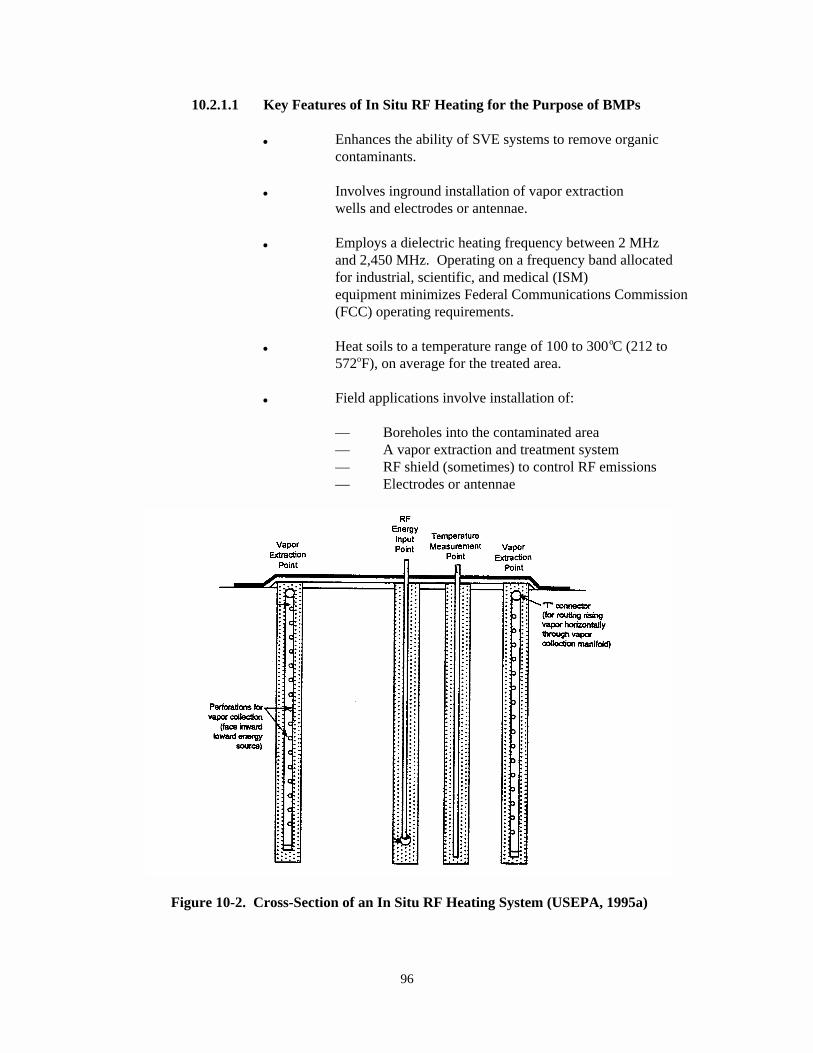
96
Figure 10-2. Cross-Section of an In Situ RF Heating System (USEPA, 1995a)
10.2.1.1 Key Features of In Situ RF Heating for the Purpose of BMPs
& Enhances the ability of SVE systems to remove organiccontaminants.
& Involves inground installation of vapor extractionwells and electrodes or antennae.
& Employs a dielectric heating frequency between 2 MHzand 2,450 MHz. Operating on a frequency band allocatedfor industrial, scientific, and medical (ISM)equipment minimizes Federal Communications Commission(FCC) operating requirements.
& Heat soils to a temperature range of 100 to 300 C (212 too
572 F), on average for the treated area.o
& Field applications involve installation of:
— Boreholes into the contaminated area— A vapor extraction and treatment system— RF shield (sometimes) to control RF emissions— Electrodes or antennae
97
10.2.2 In Situ RF Heating Technology Description
RF heating is performed by applying electromagnetic energy in the radio-frequencyband. The energy is delivered to electrodes placed into the soil cover. The mechanism ofheat generation is similar to that of a microwave oven and does not rely on the thermalproperties of the soil matrix. The power source for the process is a modified radiotransmitter. The exact frequency of operations is selected after evaluation of thedielectric properties of the soil matrix and the size of the area requiring treatment. Asthe soil is heated due to the dissipation of the RF energy, contaminants and moisture inthe soil are vaporized and pulled toward ground electrodes, which also serve as vaporextraction wells. The vaporized water may act as a steam sweep to further enhance theremoval of organic contaminants. A standard SVE system provides a vacuum to the groundelectrodes and transfers the vapors to collection or treatment facilities. Contaminantsare treated using standard vapor treatment techniques. After soil treatment is complete,the soil is allowed to cool. The SVE system may be operated during part or all of thiscooling period. The exact number of exciter and ground electrodes, electrodeconfigurations, vapor collection or treatment techniques, and other design details aregenerally site-specific (USEPA, 1995a).
10.2.3 Cross-Media Transfer Potential of In Situ RF Heating
(a) General
General cross-media transfer potentials during pre-treatment and post-treatmentactivities have been addressed in Chapter 2. In addition, the cross-media concernsdescribed for vapor extraction (Chapter 7) are generally applicable to this technology.
(b) Additional Concerns for In Situ RF Heating
& Release of contaminants (volatiles and particulates) during sitepreparation and borehole drilling.
& Migration of hot vapors to cooler zones and the resulting re-condensation of contaminants.
& Surface water intrusion from beyond the boundaries of the off-gashood into the contaminated area that is being treated.
& Downward migration of contaminant vapors to aquifer.
& Seasonal variation of the water table which causes contaminants tomove as the saturated zone fluctuates.
& The unanticipated occurrence of inorganics, such as mercury, canincrease requirements for system operation, emissions control, anddisposal of off-gases or other residues.
& Unexploded ordnance (UXOs) may pose a potential problem.
& With application of an SVE system, air can move through preferredchannels, such as around natural gravel lenses or fill materials
98
around buildings or utility lines. This can result in ineffectivecleanup, leaving areas untreated or treated to levels higher thanallowable for closure.
10.2.4 Best Management Options to Avoid Potential Cross-Media TransfersDuring In Situ RF Heating
General BMPs to prevent potential cross-media transfer of contaminants duringpre-treatment and post-treatment activities have been addressed in Chapter 2. Also,proper system design is recommended prior to implementation of the remedial treatment toavoid cross-media transfer problems during different treatment steps. However, BMPoptions to control specific cross-media transfer of contaminants for in situ RF heatingtreatments are furnished below.
RF Heating Treatment Activities - During the RF heating treatment process thefollowing activities are most commonly undertaken:
& Power Source Operation. In these systems the temperature rise occurs as aresult of ohmic or dielectric heating mechanisms. Ohmic heating arises as aresult of ionic current or conduction current that flows in materials inresponse to the applied electric field. Dielectric heating arises from thephysical distortion of the atomic or molecular structure of polar materialsin response to the applied electric field. Since the electric field changesdirection rapidly in the RF heating, the alternating physical distortiondissipates mechanical energy that is thermal energy in the material. The RFheating process raises the temperature of the soil to a range between 100 to300 C. It employs an array of metal electrodes which are placed in boreholeso
drilled through the contaminated soil. The ground electrodes are generallysupplied with 480-Volt, 3-phase power in major applications.
& Vapor Collection and Treatment. The hot gases and vapors are collected bymeans of a gas collection system and transported to the onsite vaportreatment system by means of a vacuum blower. If carbon adsorption is usedto treat vapor, compressed air may be used for system control. Steam or hotair is supplied when the carbon bed is regenerated onsite. Natural gas orpropane is used if flare is used to control vapors.
The following BMPs are generally recommended to be used, when necessary, forpreventing cross-media transfer of contaminants for the above activities:
7 Soil permeability should be tested to determine whether the vaporextraction system will be capable of efficiently collecting thevolatilized contaminants, and to optimize location of vapor extractionwells.
7 The site should be characterized in terms of the contaminants present,particularly any volatile metals. This assists in determining whichcontaminants will be volatilized by RF heating and collected by the vaporextraction system.
99
7 Buried metallic objects such as drums and tanks should be removed to theextent possible. Also, the presence of buried explosive materials shouldbe checked to eliminate explosion potential.
7 RF excitor electrodes should not be installed close to a building or otherstructure.
7 The configuration, number, depth, and orientation of extraction wellsshould be determined so that the vapor extraction system can efficientlycollect any volatilized contaminants with no zones of stagnant air.
7 The well diameter, length, and location of screened zones of extractionwells should be optimized so that the SVE system can efficiently collect anyvolatilized contaminants.
7 Extraction wells should not be located near surface water impoundments,underground storm sewers, or drains.
7 Well casings, screens, and other structural materials should be protectedfrom the potential effects of RF heating, such as the development of leaksor cracks.
7 Leaks and preferential pathways should be checked following completion ofconstruction to ensure that the SVE system can efficiently collect allvolatilized contaminants.
7 The vapor barrier system should be designed to ensure that none of thecontaminants volatilized by the RF heating are released to ambient airthrough the surface.
7 During the main treatment activities, as specified above, Radio Frequencymonitoring should be conducted to ensure that the RF field outside of thetreatment zone does not exceed the National Institute of OccupationalSafety and Health (NIOSH) or Federal Communications Commission (FCC)requirements.
7 Organic or inorganic vapor emissions should be monitored as well andappropriate emission control measures, described in Chapter 3 of thisdocument, should be used to prevent emissions above the allowable levelspecified by the regulatory agency (EPA or authorized state).
7 If the vapor treatment system yields any moisture or liquids from thetreatment process, the contaminated aqueous stream should be collected in atank or a lined/contained system. This will prevent the contaminants frommixing with the normal surface water runoff from the area and thesurrounding natural watercourse. The contaminated aqueous stream shouldbe treated or disposed in accordance with the applicable regulations.
100
7 Continued use of emissions controls may be necessary after the treatment iscompleted, since RF heating elevates the soil temperature and volatilesmay continue to be emitted for some time following treatment.
10.2.5 Waste Characteristics that May Increase the Likelihood of Cross-Media Contamination for In Situ RF Heating
The effectiveness of in situ RF heating technologies could be compromised andundue cross-media contamination may be caused under certain conditions identified inthis subsection. However, some of these limitations could possibly be overcome withvarious technology specific modifications and variations. Please refer to technology-specific references provided at the end of this chapter for additional information aboutmodifications or variations that can be used to enhance the effectiveness of in situ RFheating technologies.
� Highly saturated (greater than 25% moisture) soils will consume enormousamounts of energy as the application of the RF heat causes the water toevaporate, reducing the efficiency of the RF system.
� RF heating will not treat nonvolatile organics, inorganics, metals, andheavy oil.
� Certain RF heating technologies may not operate most effectively at depthsbelow 50 feet (USEPA, 1995a).
� Contaminants in clayey soils are usually strongly sorbed and difficult toremove (USEPA, 1995b), which reduces the efficiency of the RF system.
10.3 In Situ Vitrification
10.3.1 Definition and Scope of In Situ Vitrification (ISV) (for BMPs)
In situ vitrification (ISV) uses electrical power to heat and melt earthenmaterials (e.g., soils, sludges, mine tailings, sediments), waste materials buried inearthen materials, and other earthen-like materials contaminated with organic,inorganic, and metal-bearing hazardous and/or radioactive wastes. The molten materialcools to form a hard, monolithic, chemically inert, amorphous or crystalline product thatincorporates and immobilizes the thermally stable inorganic compounds and heavy metalsin the hazardous waste. Organic contaminants are either volatilized and captured at thehood or pyrolyzed to form more volatile constituents, which are subsequently volatilizedand captured at the hood. The slag product is glass-like with very low leachingcharacteristics.
A flowchart of the ISV process is shown in Figure 10-3. A cut-away view of atreatment cell specifying the general limits for the volume treated is shown in Figure 10-4 (USEPA, 1994a).
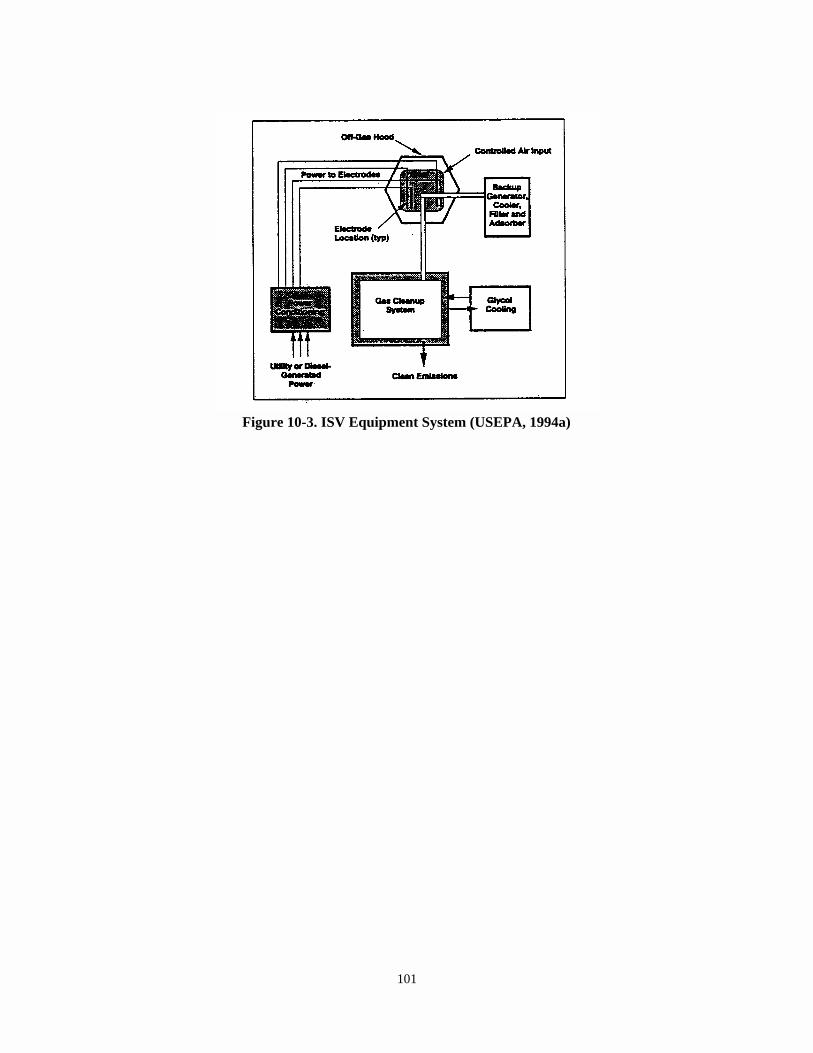
101
Figure 10-3. ISV Equipment System (USEPA, 1994a)
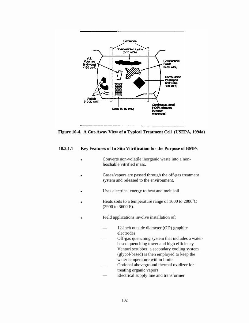
102
Figure 10-4. A Cut-Away View of a Typical Treatment Cell (USEPA, 1994a)
10.3.1.1 Key Features of In Situ Vitrification for the Purpose of BMPs
& Converts non-volatile inorganic waste into a non-leachable vitrified mass.
& Gases/vapors are passed through the off-gas treatmentsystem and released to the environment.
& Uses electrical energy to heat and melt soil.
& Heats soils to a temperature range of 1600 to 2000 Co
(2900 to 3600 F).o
& Field applications involve installation of:
— 12-inch outside diameter (OD) graphiteelectrodes
— Off-gas quenching system that includes a water-based quenching tower and high efficiencyVenturi scrubber; a secondary cooling system(glycol-based) is then employed to keep thewater temperature within limits
— Optional aboveground thermal oxidizer fortreating organic vapors
— Electrical supply line and transformer
103
10.3.2 In Situ Vitrification Technology Description
Several methods and configurations exist for the application of ISV. At a sitethat has only a relatively shallow layer of contamination, the contaminated layer may beexcavated and transported to a pit where the vitrification will take place. At othersites where the contamination is much deeper, thermal barriers could be placed along thesite to be vitrified and prevent the movement of heat and glass into adjacent areas. Thiswill force the heat energy downward and melt depths will be increased. A moreconventional approach to using ISV is to encapsulate the wastes and control the potentialfor lateral migration of contaminants within a checkerboard pattern of melts.
ISV uses a square array of electrodes up to 18 feet apart, which is inserted to adepth of 1 to 5 feet and potentially can treat down to a depth of 20 feet to remediate acontaminated area. As the vitrified zone grows, it vitrifies metals and either vaporizesor pyrolyses organic contaminants. A hood placed over the processing area is used tocollect combustion gases, which are treated in an off-gas treatment system. The gasescollected by the hood are treated by quenching, scrubbing, mist-elimination, heating,particulate filtration, and activated carbon adsorption (USEPA, 1994a).
10.3.3 Cross-Media Transfer Potential of In Situ Vitrification
(a) General
General cross-media transfer potentials during pre-treatment and post-treatmentactivities have been addressed in Chapter 2.
(b) Additional Concerns for In Situ Vitrification
& Release of contaminants (volatiles and particulates) during sitepreparation.
& Possible hazards due to high voltage electrical fluxes.
& Downward migration of melted contaminants or contaminant vapors toaquifer.
& Contaminant vapors can be released away from the treatment zone ifthere is an open pathway (e.g., pipe, french drain) that interceptsthe treatment zone. Sites should be inspected for open subsurfaceconduits prior to applying ISV.
10.3.4 Best Management Options to Avoid Potential Cross-Media TransfersDuring ISV
During ISV treatment activities, measures may need to be taken to control fugitiveemissions and to prevent release of contaminated media to the natural environment. Thefollowing BMPs are generally recommended to be used when necessary for preventing cross-media transfer of contaminants for the above activities:
104
7 During large-scale operations, pumping wells and/or intercept trenchesshould be installed around the treatment zone. This will preventgroundwater from flowing through a contaminated treatment zone.
7 If open subsurface conduits are found, they should be disrupted (e.g.,collapsed, broken, filled) prior to treatment.
7 The ISV treatment activities should be conducted under a controlledenvironment when the off gases, volatiles, dusts, etc. are being emitted atlevels above the regulatory limit. The VOC emissions associated with theseactivities should be controlled by capturing these emissions and thentreating the captured vapor/air.
7 To minimize disruption of contaminated soil, a thin layer of clean coversoil should be placed over the contaminated area prior to the placement ofthe off-gas collection hood. This practice eliminates the possibilities ofairborne contamination and tracking of contaminated material across thesite.
7 If the vapor treatment system yields any moisture or liquids from thetreatment process, the contaminated aqueous streams should be collected ina tank or a lined/contained system. This will prevent the contaminants frommixing with the normal surface water runoff from the area and thesurrounding natural watercourse. The contaminated aqueous stream shouldbe treated or disposed in accordance with the applicable regulations.
7 Typically 20-40% volume reductions occur as a result of the meltingprocess, which can lead to subsidence within the treated zone. Clean soilis generally placed to fill in the subsided region as a standard practice,and this should be consistently followed in all ISV treatment.
7 Arrangements should be made for leaving the vitrified mass in place orexhuming it and disposing of it properly.
7 If the vitrified soil is to be left in place, clean soil should be backfilledover it to encourage regrowth of vegetation.
7 Electrodes may be removed, decontaminated, reused, disposed of, or left inthe vitrified mass.
7 Drums or tanks filled with liquid, if removed from the treatment area,should be disposed of in compliance with the applicable state and/orfederal regulations.
10.3.5 Waste Characteristics that May Increase the Likelihood of Cross-Media Contamination for In Situ Vitrification Technologies
The effectiveness of in situ vitrification technologies could be compromised andundue cross-media contamination may be caused under certain conditions identified in
105
this subsection. However, some of these limitations could possibly be overcome withvarious technology specific modifications and variations. Please refer to technology-specific references provided at the end of this chapter for additional information aboutmodifications or variations that can be used to enhance the effectiveness of in situvitrification technologies.
� Organic contents of greater than 10% by weight within the soil matrix mightrequire additional or modified off-gas treatment components. Alternatively, soils of higher organic contents (e.g., exceeding 20%) havebeen successfully treated by slowing the melting rate to levels that allowacceptable heat removal rates in the off-gas treatment system (Campbell,1995).
� Pockets of flammable liquid or vapor sealed in containers beneath the soilsurface can create a potential explosion hazard.
� In cases where heavy metal immobilization is desired, soils containing lessthan 50% by weight of glass formers (e.g., aluminum and silica), and < 2% byweight of alkali compounds (e.g., sodium and potassium), may requiremodification with additives to obtain desired melt and vitrified productcharacteristics (Campbell, 1995).
� Depths greater than 20 feet (6 meters) require higher power-level equipmentbecause of the larger masses and volume that are being treated (Campbell,1995).
� Soils that contain inorganic debris greater than 55% by volume areextremely difficult to treat with this technology (Campbell, 1995).
� Soils with high ground water recharge rates require special methods tolimit recharge to acceptable rates.
10.4 In Situ Soil Flushing
10.4.1 Definition and Scope of In Situ Soil Flushing (for BMPs)
In situ soil flushing is the extraction of contaminants from the soil with water orother suitable aqueous solutions. Soil flushing is accomplished by passing theextraction fluid through in-place soils using an injection or infiltration process. Extraction fluids must be recovered and, when possible, are recycled. Typically, soilflushing is used in conjunction with other treatments that destroy contaminants or removethem from the extraction fluid and groundwater (USEPA, 1992a).
In situ soil flushing includes conventional and unconventional techniques. Theconventional techniques include well-and-capture methods in the vadose zone and pump-and-treat systems in the saturated zone. Unconventional techniques consist of primary,secondary, and tertiary recovery techniques (USEPA, 1993a).

106
Figure 10-5 is a schematic diagram of an in situ soil flushing system in which thetreatment solvent is injected into the soil (USEPA, 1993a). Figure 10-6 is a schematicdiagram of an in situ soil flushing sprinkler system (USEPA, 1993a). Figure 10-7 is across-section of an in situ soil flushing system that uses spray application (USEPA,1991b).
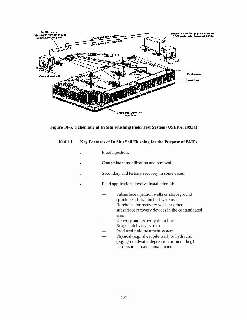
107
Figure 10-5. Schematic of In Situ Flushing Field Test System (USEPA, 1993a)
10.4.1.1 Key Features of In Situ Soil Flushing for the Purpose of BMPs
& Fluid injection.
& Contaminant mobilization and removal.
& Secondary and tertiary recovery in some cases.
& Field applications involve installation of:
— Subsurface injection wells or abovegroundsprinkler/infiltration bed systems
— Boreholes for recovery wells or othersubsurface recovery devices in the contaminatedarea
— Delivery and recovery drain lines— Reagent delivery system— Produced fluid treatment system— Physical (e.g., sheet pile wall) or hydraulic
(e.g., groundwater depression or mounding)barriers to contain contaminants
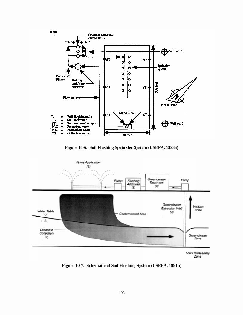
108
Figure 10-6. Soil Flushing Sprinkler System (USEPA, 1993a)
Figure 10-7. Schematic of Soil Flushing System (USEPA, 1991b)
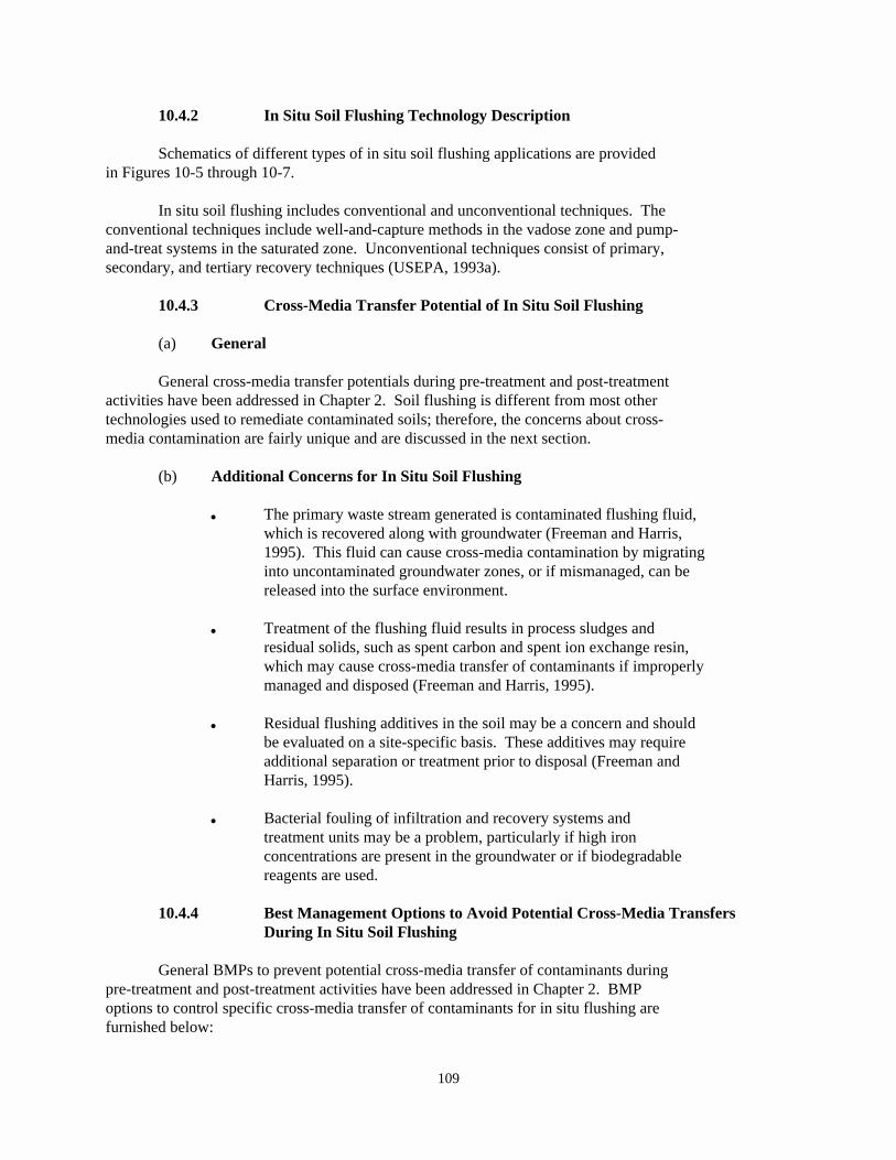
109
10.4.2 In Situ Soil Flushing Technology Description
Schematics of different types of in situ soil flushing applications are providedin Figures 10-5 through 10-7.
In situ soil flushing includes conventional and unconventional techniques. Theconventional techniques include well-and-capture methods in the vadose zone and pump-and-treat systems in the saturated zone. Unconventional techniques consist of primary,secondary, and tertiary recovery techniques (USEPA, 1993a).
10.4.3 Cross-Media Transfer Potential of In Situ Soil Flushing
(a) General
General cross-media transfer potentials during pre-treatment and post-treatmentactivities have been addressed in Chapter 2. Soil flushing is different from most othertechnologies used to remediate contaminated soils; therefore, the concerns about cross-media contamination are fairly unique and are discussed in the next section.
(b) Additional Concerns for In Situ Soil Flushing
& The primary waste stream generated is contaminated flushing fluid,which is recovered along with groundwater (Freeman and Harris,1995). This fluid can cause cross-media contamination by migratinginto uncontaminated groundwater zones, or if mismanaged, can bereleased into the surface environment.
& Treatment of the flushing fluid results in process sludges andresidual solids, such as spent carbon and spent ion exchange resin,which may cause cross-media transfer of contaminants if improperlymanaged and disposed (Freeman and Harris, 1995).
& Residual flushing additives in the soil may be a concern and shouldbe evaluated on a site-specific basis. These additives may requireadditional separation or treatment prior to disposal (Freeman andHarris, 1995).
& Bacterial fouling of infiltration and recovery systems andtreatment units may be a problem, particularly if high ironconcentrations are present in the groundwater or if biodegradablereagents are used.
10.4.4 Best Management Options to Avoid Potential Cross-Media TransfersDuring In Situ Soil Flushing
General BMPs to prevent potential cross-media transfer of contaminants duringpre-treatment and post-treatment activities have been addressed in Chapter 2. BMPoptions to control specific cross-media transfer of contaminants for in situ flushing arefurnished below:
110
7 A thorough site characterization should be conducted to determine allleachable contaminants present.
7 Depth to groundwater (including any seasonal variations) and presence offree product, if any, should be identified. All free product shouldgenerally be recovered before any treatment begins.
7 During construction of injection wells, care should be taken to properly:
— Anchor wells— Install suitable screen meshes— Protect the wellhead
7 The recovery system should have adequate capacity to collect injectedfluids and groundwater, taking into account maximum practical aquiferyield.
7 If bacterial fouling of any part of the treatment system is a problem, theaddition of compounds to control bacterial growth should be considered.
10.4.5 Waste Characteristics that May Increase the Likelihood of Cross-Media Contamination for In Situ Flushing Technologies
Under the following conditions the effectiveness of in situ soil flushing (ascategorized for BMPs) could be compromised, and could cause undue cross-mediacontamination.
� Soils containing a high percentage of silt- and clay-sized particlestypically are strongly adsorbed and are difficult to remove. These soilsalso tend to be less permeable (Freeman and Harris, 1995). The applicationof in situ soil flushing to soils with these characteristics may increasethe need to use additives and reduce the efficiency of contaminant removal. Reduced contaminant removal may require the treatment of very large volumesof groundwater, which may increase the potential for cross-mediacontamination.
� Soils with low hydraulic conductivity (e.g., K < 1.0 x 10 cm/sec) will-5
limit the ability of flushing fluids to percolate through the soil in areasonable time frame (Freeman and Harris, 1995).
� Moisture content can affect the amount of flushing fluids required. Drysoils will require more flushing fluids initially to mobilize contaminants(Freeman and Harris, 1995).
� High humic content and high cation exchange capacity tend to reduce theremoval efficiency of soil flushing (Freeman and Harris, 1995).
� Multiple factors, including high concentrations of fine sedimentarymaterials, inorganic precipitation, formation of stable emulsions, or
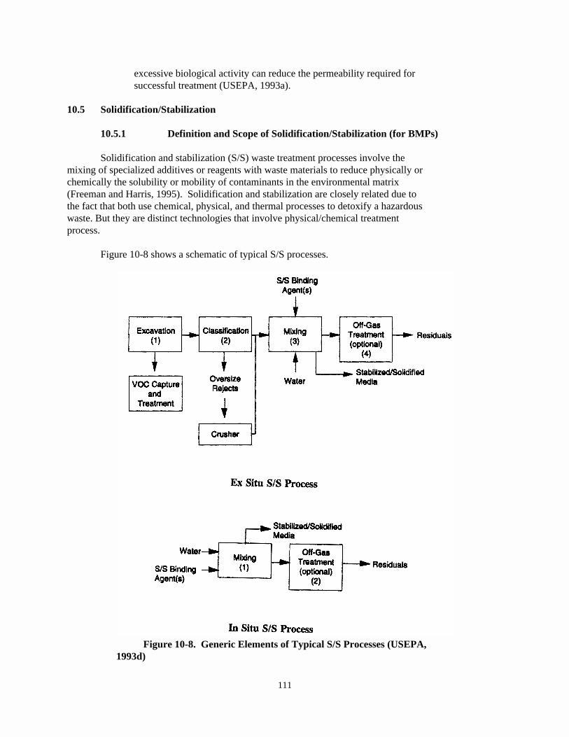
111
Figure 10-8. Generic Elements of Typical S/S Processes (USEPA,1993d)
excessive biological activity can reduce the permeability required forsuccessful treatment (USEPA, 1993a).
10.5 Solidification/Stabilization
10.5.1 Definition and Scope of Solidification/Stabilization (for BMPs)
Solidification and stabilization (S/S) waste treatment processes involve themixing of specialized additives or reagents with waste materials to reduce physically orchemically the solubility or mobility of contaminants in the environmental matrix(Freeman and Harris, 1995). Solidification and stabilization are closely related due tothe fact that both use chemical, physical, and thermal processes to detoxify a hazardouswaste. But they are distinct technologies that involve physical/chemical treatmentprocess.
Figure 10-8 shows a schematic of typical S/S processes.

112
10.5.1.1 Key Features of Solidification/Stabilization for the Purpose ofBMPs
& Requires mixing of reagents, either on- or off-site.
& Immobilizes contaminants.
& Like other immobilization technologies, does notdestroy inorganic waste, but may alter or changeorganic waste.
& Stabilization can be combined with encapsulation orother immobilization technology(ies).
& May increase total volume of materials that must behandled as waste.
& Wastes treated with S/S may be amenable to reusefollowing treatment.
& Field application may involve installation of any orall of the following:
— Auger type drilling and mixing equipment for insitu applications
— Dust collection systems— Volatile emission control systems— Bulk storage tanks
10.5.2 Solidification and Stabilization Technology Description
Solidification refers to processes that encapsulate the waste in a monolithicsolid with structural integrity. The encapsulation may be that of compacted fine wasteparticles or of a large block or container of wastes. Solidification does not necessarilyinvolve a chemical interaction between the waste and the solidifying reagents, but maymechanically bind the waste in the monolith. Contaminant migration is restricted byvastly decreasing the surface area exposed to leaching and/or by isolating the wastewithin an impervious capsule (USEPA, 1994c).
Stabilization refers to processes that reduce risk posed by a waste by convertingthe contaminants into a less soluble, mobile, or toxic form. The physical nature of thewaste is not necessarily changed. Phosphates, sulfides, carbonates, etc. can be used astreatment reagent.
In many instances stabilization is exclusive of solidification. Stabilizedproduct should have low leaching characteristics. Many of the reagents used for S/Sprocess are also used in other chemical treatment processes such as dechlorination.
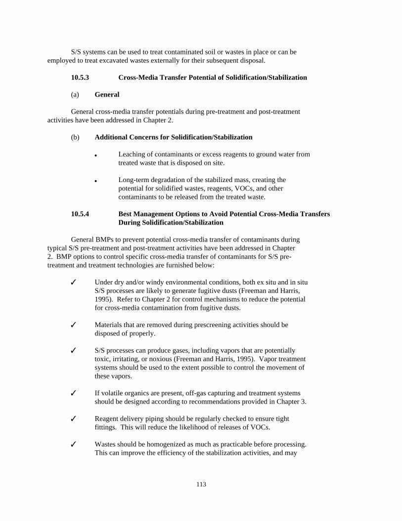
113
S/S systems can be used to treat contaminated soil or wastes in place or can beemployed to treat excavated wastes externally for their subsequent disposal.
10.5.3 Cross-Media Transfer Potential of Solidification/Stabilization
(a) General
General cross-media transfer potentials during pre-treatment and post-treatmentactivities have been addressed in Chapter 2.
(b) Additional Concerns for Solidification/Stabilization
& Leaching of contaminants or excess reagents to ground water fromtreated waste that is disposed on site.
& Long-term degradation of the stabilized mass, creating thepotential for solidified wastes, reagents, VOCs, and othercontaminants to be released from the treated waste.
10.5.4 Best Management Options to Avoid Potential Cross-Media TransfersDuring Solidification/Stabilization
General BMPs to prevent potential cross-media transfer of contaminants duringtypical S/S pre-treatment and post-treatment activities have been addressed in Chapter2. BMP options to control specific cross-media transfer of contaminants for S/S pre-treatment and treatment technologies are furnished below:
7 Under dry and/or windy environmental conditions, both ex situ and in situS/S processes are likely to generate fugitive dusts (Freeman and Harris,1995). Refer to Chapter 2 for control mechanisms to reduce the potentialfor cross-media contamination from fugitive dusts.
7 Materials that are removed during prescreening activities should bedisposed of properly.
7 S/S processes can produce gases, including vapors that are potentiallytoxic, irritating, or noxious (Freeman and Harris, 1995). Vapor treatmentsystems should be used to the extent possible to control the movement ofthese vapors.
7 If volatile organics are present, off-gas capturing and treatment systemsshould be designed according to recommendations provided in Chapter 3.
7 Reagent delivery piping should be regularly checked to ensure tightfittings. This will reduce the likelihood of releases of VOCs.
7 Wastes should be homogenized as much as practicable before processing. This can improve the efficiency of the stabilization activities, and may
114
help to reduce spillage and other problems related to encounteringirregular masses during the mixing process.
7 Treated waste should be disposed in a covered area and above the groundwatertable.
10.5.5 Waste Characteristics That May Increase the Likelihood of Cross-Media Contamination for Solidification and StabilizationTechnologies
The effectiveness of solidification and stabilization technologies could becompromised and undue cross-media contamination may be caused under certain conditionsidentified in this subsection. However, some of these limitations could possibly beovercome with various technology-specific modifications and variations. Please refer totechnology-specific references provided at the end of this chapter for additionalinformation about modifications or variations that can be used to enhance theeffectiveness of solidification and stabilization technologies.
� Physical mechanisms that can interfere with the S/S process include:
— Incomplete mixing due to the presence of high moisture or organicchemical content resulting in only partial wetting or coating of thewaste particles with the stabilizing and binding agents and theaggregation of untreated waste into lumps (Freeman and Harris,1995).
— Disruption of the gel structure of the curing cement or pozzolanicmixture by hydrophilic organics in the soil (Freeman and Harris,1995).
— Undermixing of dry or pasty wastes (Freeman and Harris, 1995).
� Chemical mechanisms that can interfere with the S/S process include:
— Chemical adsorption— Precipitation— Nucleation
� Other factors that can interfere include:
— Precise tailoring of waste composition to the S/S process used(USEPA, 1994c).
— Waste containing oil and grease in moderate to high concentrations.
For more details on the various chemical interactions that can reduce theeffectiveness, and thereby the stability, of S/S treatments, see Freeman and Harris,1995, and USEPA, 1993b.
10.6 Excavation and Off-Site Disposal
115
10.6.1 Definition and Scope of Excavation and Off-Site Disposal (for BMPs)
When a site is remediated by excavation and off-site disposal, the contaminatedmaterial (typically a solid or semi-solid material such as soil or sludge) is excavated,then transported off-site for treatment and/or disposal.
10.6.1.1 Key Features of Excavation and Off-Site Disposal for the Purposeof BMPs
& Excavation or collection of contaminated soils,followed by piling or mixing of the soils.
& Containerization or temporary storage of thecontaminated soils or solid media.
& Shipping of soils off-site for disposal.
& Field applications involve installation of a temporarycanopy, liner, or other physical barrier as presentedin Chapter 3 that minimizes movement of materials fromthe site by wind, water, or any other mechanism.
10.6.2 Excavation and Off-Site Disposal Technology Description
Excavation and off-site disposal primarily involve equipment that is widely usedin the construction or non-hazardous solid waste disposal industries, such asexcavators, earth movers or backhoes, dump trucks, and containers of various shapes,sizes, and materials. However, in general, hazardous waste excavation and off-sitedisposal activities require significantly more attention to personal protection andsafety, including provisions for worker protection (special clothing, decontaminationtechniques, etc.) and equipment decontamination.
10.6.3 Cross-Media Transfer Potential of Excavation and Off-Site Disposal
(a) General
The general cross-media concerns that are provided in Chapter 2, especially thosethat refer to excavation and construction activities, are especially relevant to thistechnology. Table 2-1 presents information on the contribution of remedial activities,including excavation, materials handling, and transportation, that are of concern to allremedial technologies including this option.
(b) Additional Concerns for Excavation and Off-Site Disposal
Concerns for excavation and off-site disposal center around the potential forcross-media transfer during materials handling and transportation activities. Carefulattention should be paid to information presented in those chapters, particularly as itrelates to the handling and transportation of contaminated wastes.
116
10.6.4 Best Management Options to Avoid Potential Cross-Media TransfersDuring Excavation and Off-Site Disposal
General BMPs to prevent potential cross-media transfer of contaminants duringexcavation and off-site disposal activities have been addressed in Chapters 2 and 3. TheBMP options presented in those chapters are most applicable to this technology. Theyinclude:
7 Entry to the active site should be limited to avoid unnecessary exposure andrelated transfer of contaminants, especially during site preparation andstaging.
7 Avoid entering the contaminated area. In unavoidable circumstances, builda temporary decontamination area, which could be later used during cleanupactivities. Any above-ground and underground source of contaminants shouldbe identified and located prior to starting excavation of the contaminatedarea.
7 Fugitive dust emissions should be controlled during excavation by sprayingwater or other materials to keep the ground moist or covered. During wetweather or rainfall no water spraying would be needed. See Chapter 3 formore information on materials that can be used to control fugitive dustemissions.
7 During transportation of contaminated soils or solid media, covers orliners should be used to prevent dust and VOC emissions. These temporarycovers on trucks or other hauling equipment should be installed with care tominimize possibilities for the waste to come into contact with high windsduring transport.
7 Any offsite runoff should be prevented from entering and mixing with on-site contaminated media by building earthen berms or adopting similar othermeasures, as outlined in Table 3-4.
7 Provisions should generally be made to capture on-site surface water runoffby diverting it to a controlled depression-area or lined pit.
7 Covers, and if necessary, liners, should be used at all times whencontaminated materials are being stored. Covers should be used on trucksthat are moving materials around and from the site. See Chapter 3 fordetails on covers and liners that should be considered for use duringexcavation, storage, and transportation.
10.6.5 Waste Characteristics that May Increase the Likelihood of Cross-Media Contamination for Excavation and Off-Site DisposalTechnologies
117
Under the following conditions the effectiveness of excavation and off-sitedisposal (for BMPs) could be compromised, and could cause undue cross-mediacontamination.
� When high volumes of soils are to be disposed of, this option may not be verycost-effective.
� For highly explosive materials, a simple excavation and disposal may notprovide the safest method of handling the waste.
10.7 References
1. Campbell, Brett E. 1995. Geosafe Corporation, Comments on BMP Workshop Summary-Other Physical/Chemical Technologies, Personal Communication to Subijoy Dutta,USEPA.
2. Dev, Harsh. 1995. IIT Research Institute, Letter Report on RF In Situ Heating andSoil Decontamination Process, Personal Communication to Subijoy Dutta, USEPA.
3. Freeman, Harry M. and Eugene F. Harris. 1995. Hazardous Waste Remediation: Innovative Treatment Technologies, Technomic Publishing Co., Inc., Lancaster,PA.
4. USEPA. 1995a. SITE Technology Capsule: IITRI Radio Frequency HeatingTechnology, EPA/540/R-94/527a, March.
5. USEPA. 1995b. Innovative Technology Evaluation Report, Radio Frequency Heating,KAI Technologies Inc., EPA/540/R-94/528, April.
6. USEPA. 1995c. In Situ Remediation Technology Status Report: SurfactantEnhancements, EPA/542-K-94/003, Office of Solid Waste and Emergency Response.
7. USEPA. 1995d. In Situ Remediation Technology Status Report: Cosolvents,EPA/542-K-94/006, Office of Solid Waste and Emergency Response.
8. USEPA. 1995e. In Situ Remediation Technology Status Report: Hydraulic andPneumatic Fracturing, EPA/542/K-94/005, Office of Solid Waste and EmergencyResponse.
9. USEPA. 1995f. In Situ Remediation Technology Status Report: Electrokinetics,EPA/542/K-94/007, Office of Solid Waste and Emergency Response.
10. USEPA. 1995g. Dynaphore Inc. Forager Sponge Technology, Innovative TechnologyEvaluation Report, EPA/540/R-94/522, Office of Research and Development,Washington, DC, June.
11. USEPA. 1995h. Geosafe Corporation In Situ Vitrification Innovative TechnologyEvaluation Report, EPA/540/R-94/520, Office of Research and Development,Washington, DC, March.
118
12. USEPA. 1995i. IITRI Radio Frequency Heating Technology, Innovative TechnologyEvaluation Report, EPA/540/R-94/527, Office of Research and Development,Washington, DC,
13. USEPA. 1995j. SITE Emerging Technology Summary, Reclamation of Lead fromSuperfund Waste Material Using Secondary Lead Smelters, EPA/540/SR-95/504,Center for Environmental Research Information, Cincinnati, OH.
14. USEPA. 1995k. SITE Emerging Technology Bulletin, Waste Vitrification ThroughElectric Melting, Ferro Corporation, EPA/540/F-95/503, Risk ReductionEngineering Laboratory, Cincinnati, OH, March.
15. USEPA. 1995l. SITE Emerging Technology Bulletin, Electrokinetic SoilProcessing, Electrokinetics, Inc., EPA/540/F-95/504, Risk Reduction EngineeringLaboratory, Cincinnati, OH, March.
16. USEPA. 1995m. SITE Technology Capsule, Texaco Gasification Process, EPA 540/R-94/514a, Center for Environmental Research Information, Cincinnati, OH. April.
17. USEPA. 1995n. SITE Technology Capsule, KAI Radio Frequency Heating Technology, EPA/540/R-94/528a, Center for Environmental Research Information, Cincinnati,OH, January.
18. Drennan, Dawn. 1994. Technical Answers, Lasagna Process Treats Contaminants. Environmental Protection, Stevens Publishing, Waco, TX, September.
19. USEPA. 1994a. Engineering Bulletin-In Situ Vitrification Treatment, EPA/540/S-94/504, Office of Research and Development, Cincinnati, OH, October.
20. USEPA. 1994b. Emerging Technology Bulletin, Institute of Gas Technology, FluidExtraction-Biological Degradation Process, EPA/540/F-94/501, March.
21. USEPA. 1994c. William C. Anderson, ed. Innovative Site Remediation Technology,Solidification/Stabilization, Volume 4, EPA/542/B-94/001, Office of Solid Wasteand Emergency Response.
22. USEPA. 1994d. Innovative Site Remediation Technology: Chemical Treatment,Volume 2, EPA/542/B-94/004, Office of Solid Waste and Emergency Response.
23. USEPA. 1994e. Physical/Chemical Treatment Technology Resource Guide, EPA/542/B-94/008, Office of Solid Waste and Emergency Response, Technology InnovationOffice, Washington, DC.
24. USEPA. 1994f. SITE Demonstration Bulletin, SFC Oleofiltration System, InPlantSystems, Inc., EPA/MR-94/525, Risk Reduction Engineering Laboratory, Cincinnati,OH, October.
119
25. USEPA. 1994g. SITE Technology Capsule, InPlant Systems, Inc., SFC 0.5Oleofiltration System, EPA/540/R-94/525a, Center for Environmental ResearchInformation, Cincinnati, OH, December.
26. USEPA. 1993a. Innovative Site Remediation Technology: Soil Washing/SoilFlushing, Volume 3, EPA/542/B-93-012, November.
27. USEPA. 1993b. Technical Resource Document-Solidification/Stabilization and itsApplication to Waste Materials, EPA/530/R-93/012, Office of Research andDevelopment, Washington, DC, June.
28. USEPA. 1993c. Accutech Pneumatic Fracturing Extraction and Hot Gas Injection,Phase I, Applications Analysis Report, EPA/540/AR-93/509, Office of Research andDevelopment, Washington, DC, July.
29. USEPA. 1993d. Engineering Bulletin, Solidification/Stabilization of Organicsand Inorganics, EPA/540/S-92/015, Office of Research and Development,Cincinnati, OH, May.
30. USEPA. 1992a. Guide for Conducting Treatability Studies Under CERCLA SolventExtraction, Interim Guidance (and Quick Reference Fact Sheet), EPA/540/R-92/016Aand B, Office of Emergency and Remedial Response, August.
31. USEPA. 1992b. Seminar Publication: Organic Air Emissions from Waste ManagementFacilities, EPA/625/R-92/003, August.
32. USEPA. 1992c. Guide for Conducting Treatability Studies Under CERCLA, ChemicalDehalogenation (and Quick Reference Fact Sheet), EPA/540/R-92/013A and B, Officeof Solid Waste and Emergency Response, May.
33. USEPA. 1992d. Engineering Bulletin-Supercritical Water Oxidation, EPA/540/S-92/006, Office of Research and Development, Cincinnati, OH, September.
34. USEPA. 1992e. A Citizen's Guide to Glycolate Dehalogenation-Technology FactSheet, EPA/542/F-92/005, Office of Solid Waste and Emergency Response,Technology Innovation Office.
35. USEPA. 1992f. A Citizen's Guide to In Situ Soil Flushing-Technology Fact Sheet, EPA/542/F-92/007, Office of Solid Waste and Emergency Response, TechnologyInnovation Office.
36. USEPA. 1991a. Engineering Bulletin: Control of Air Emissions From MaterialsHandling During Remediation, EPA/540/2-91/023, October.
37. USEPA. 1991b. Engineering Bulletin-In Situ Soil Flushing, EPA/540/2-91/021,Office of Research and Development, Cincinnati, OH, October.
120
38. USEPA. 1991c. Engineering Bulletin-Chemical Oxidation Treatment, EPA/540/2-91/025, Office of Emergency and Remedial Response, Washington, DC, Office ofResearch and Development, Cincinnati, OH, October.
39. USEPA. 1991d. Engineering Bulletin-Granular Activated Carbon Treatment,EPA/540/2-91/024, Office of Research and Development, Cincinnati, OH, October.
40. USEPA. 1990. Engineering Bulletin-Chemical Dehalogenation Treatment: APEGTreatment, EPA/540/2-90/015, Office of Research and Development, Cincinnati, OH,September.
121
11.0 Chapter Eleven: FIELD VALIDATION and CASE STUDIES of BMPs
This chapter provides information on the field use of best management practices(BMPs) for controlling cross-media transfer of pollutants at sites where soils treatmenthas been completed or is currently under progress. The information was compiled with thefollowing objectives:
� Provide highlights of BMPs observed at each site,
� Provide details on how certain BMPs were used at different sites,
� Compare recommended BMPs with the current practices in the field, and
� Incorporate new or modified BMPs in the relevant sections of the BMPsguidance.
The information contained in this chapter was developed by examining detailed siteworkplans and soils treatment reports, as well as by interviewing site remediationmanagers and observing remediation activities at volunteering sites. In total,information on the field use of BMPs was obtained from eight sites (located in the statesof Colorado, Connecticut, Maine, Maryland, Minnesota, and Virginia) covering thefollowing six types of soils treatment technologies: containment, soil washing/soilleaching, soil-vapor extraction, thermal treatment, bioremediation, and chemical basedstabilization.
This field validation study was undertaken at a limited number of sites due to timeconstraints and ready availability of volunteering sites. However, after this guidanceis used at various sites, EPA plans to contact additional volunteering sites fromdifferent parts of the country to get their experience with the recommended BMPs. Thisfeedback would be incorporated in the next update of the BMPs guidance.
Table 11-1 summarizes key characteristics of the sites EPA studied to obtaininformation on the field use of BMPs. The first five case studies (Site Nos. 1-5) arebased on records provided by state personnel who had acted as coordinators of RCRACorrective Action Programs at the respective sites. These personnel also participated inEPA's RCRA National Program Meeting in September 1996 to discuss the BMPs used at thesites. The sixth case study (Site No. 6) is based on records provided by a federalcontractor acting as the planner and coordinator of environmental restoration activitiesat the site. The last two case studies (Site Nos. 7 and 8) are based on informationobtained by EPA during site visits when detailed discussions were held with site managerson their use of BMPs in remediation currently in progress.
Sections 11.1 through 11.8 provide details on the field use of BMPs at each site. Each section briefly describes site remediation activities at the site followed by a morein-depth description of the BMPs as used, and some views and discussion on the case study. Finally, Section 11.9 provides a summary list of selected BMPs used at each site andcomparisons of those BMPs with the recommended BMPs in Chapters 4 through 10 of thisguidance.

122
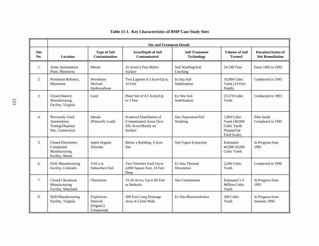
123
Table 11-1. Key Characteristics of BMP Case Study Sites
Site and Treatment Details
Site Type of Soil Area/Depth of Soil Soil Treatment Volume of Soil Duration/Status ofNo. Location Contamination Contaminated Technology Treated Site Remediation
1 Army Ammunition Metals 16 Acres/2 Feet Below Soil Washing/Soil 24,748 Tons From 1993 to 1995Plant, Minnesota Surface Leaching
2 Petroleum Refinery, Petroleum- Two Lagoons 0.5 Acre/Up to In Situ Soil 18,000 Cubic Conducted in 1995Minnesota Derived 10 Feet Stabilization Yards (10 Feet
Hydrocarbons Depth)
3 Closed Battery Lead Plant Site of 4.5 Acres/Up Ex Situ Soil 25,578 Cubic Conducted in 1993Manufacturing to 3 Feet Stabilization YardsFacility, Virginia
4 Previously Used Metals Scattered Distribution of Size Separation/Soil 1,000 Cubic Pilot StudyAmmunition (Primarily Lead) Contaminated Areas Over Washing Yards (40,000 Completed in 1995Testing/Disposal 435 Acres/Mostly on Cubic YardsSite, Connecticut Surface Planned for
Field Scale)
5 Closed Electronics Spent Organic Below a Building, 3 Acre Soil Vapor Extraction Estimated In Progress fromComponent Solvents Site 40,000-50,000 1995Manufacturing Cubic YardsFacility, Maine
6 DOE Manufacturing VOCs in Two Trenches Each Up to Ex Situ Thermal 2,200 Cubic Conducted in 1996Facility, Colorado Subsurface Soil 4,000 Square Feet, 10 Feet Desorption Yards
Deep
7 Closed Chromium Chromium 15-20 Acres; Up to 80 Feet Site Containment Estimated 1-2 In Progress fromManufacturing or Bedrock Million Cubic 1991Facility, Maryland Yards
8 DoD Manufacturing Explosives- 300 Foot Long Drainage Ex Situ Bioremediation 500 Cubic In Progress fromFacility, Virginia Derived Area; 4-5 Feet Wide Yards Summer 1996
(Organic)Compounds
124
11.1 Soil Washing/Soil Leaching to Treat Metals Contaminated Soil at an Army AmmunitionPlant in Minnesota (Site 1)
11.1.1 Description of Site Remediation Activities
From 1993 through 1995, metals contaminated soil was excavated from an area of 16acres in an Army ammunition plant in Minnesota and treated, when possible, by soilwashing/soil leaching on site. The treatment goals were to reduce the concentration oflead to a regulatory level of 300 mg/kg and the concentration of several other heavymetals to the background levels. The site was previously used as an open burning area forscrap primers, fuses, and explosives related to small caliber arms and rifle grenades. The metals contamination was generally limited to the uppermost three feet across thesite. The site was not contaminated with VOCs, SVOCs, or cyanide. The groundwater was notimpacted by soil contamination. However, twenty disposal areas were identified at thissite which were also excavated and remediated. The materials found in the disposal areasincluded ordnance, high explosive items, cast-iron pots, crushed drums, characterizedchemical substances, and miscellaneous scrap metal, wood, concrete and glass debris. Allmaterials excavated from the disposal areas were identified and sorted for propertreatment or disposal off site.
The site remediation was performed according to closure plans approved under aRCRA Hazardous Waste TSD Permit and the Federal Facility Agreement (FFA) prepared for theInstallation Restoration Program (IRP) of the Army ammunition plant. The site closureactivities included site preparation, disposal area investigations and excavation,metals-contaminated soil excavation and treatment, ordnance clearance, hazardous andnon-hazardous waste management, and site restoration to allow unrestricted future use ofthe site.
Approximately 24,748 tons of contaminated soil were excavated at this site. Atotal of 246 tons of metal concentrate were recovered during soil washing/soil leachingactivities. A total of 12,797 tons of soil were successfully treated and backfilled asclean soil. A total of 7,125 tons of soil were treated to become non-hazardous and thesewastes are temporarily being stored on site. Approximately 4,555 tons of soil,characterized as hazardous and non treatable on site, were recycled off site at a smelter.
11.1.2 BMPs Used to Prevent Cross-Media Transfer of Pollutants
Because the remediated site was located in a large federal facility (2,300 acres)where several private companies operated as facility tenants, there was a potential forhuman exposure to lead and other toxic metals from fugitive dust emission during siteexcavation, soil transportation and soil treatment. There was also a potential forcross-media transfer of pollutants in uncontrolled surface water run-on to and run-offfrom the site. Another concern was that a spillage and/or improper disposal of soiltreatment residuals might result in groundwater contamination. To address these cross-media transfer concerns, various BMPs were used at this site during site remediation. Alist of 12 BMPs, as introduced in different remedial stages, is given below.
Site Preparation and Staging
125
a. Delineating the actual limits of soil contamination by lead and other heavymetals.
b. Establishing an exclusion zone and a decontamination pad to control alltraffic to/from the site.
c. Refurbishing the existing oil treatment pad/area to meet the staging needsof soil washing/soil leaching on site.
d. Conducting an in-depth characterization of new disposal areas located onsite.
e. Removing and sorting the debris found in disposal areas.f. Installing an air quality monitoring system at the site.
Pre-Treatment
g. Building an earthen berm for controlling surface water run-on to and run-off from the site.
h. Arranging for dust suppression during site remediation.i. Covering haul trucks and excavated soil stockpiles.
Soil Treatment
j. Reusing stormwater as process makeup water.k. Recycling process wastewater in soil treatment.
Post-Treatment
l. Reusing treated/clean soil in restoring the site.
Additional details on the field application of each of these BMPs are given below.
a. Delineating the Actual Limits of Soil Contamination by Lead and Other HeavyMetals. Additional soil boring and field analysis of total lead concentrations wereperformed as one of the earliest activities of site remediation in 1993 to furtherdelineate the previously estimated limits of soil contamination. A total of 326 soilborings were made to collect soil samples at 6- and 12-inch depths every 25 feet along theestimated limits. X-ray fluorescence (XRF) analysis was used to give a fielddetermination of soil quality. If samples from both depths at a given soil boring wereshown to have XRF lead concentrations of less than 100 ppm, the location was considered tobe non-contaminated. Additional XRF samples were then collected in an attempt todelineate the boundary of contamination within five feet of the actual zone ofcontamination (which also represented the horizontal limits of excavation). Theseactivities limited the total quantities of soil excavated and treated during siteremediation.
b. Establishing an Exclusion Zone and a Decontamination Pad to Control All TrafficTo/From the Site. After verifying the boundaries of contamination with laboratoryanalysis of soil samples, the exclusion zone was established by providing a buffer zoneoutside the finalized limits of contamination. Access to the exclusion zone was limitedto qualified personnel wearing the appropriate personnel protective equipment and toperform only the site remediation activities approved by the site closure plan. After
126
establishing the exclusion zone, a decontamination pad was constructed for vehicle,equipment, and personnel decontamination. All traffic into and out of the exclusion zonewent through the decontamination pad. The decontamination pad was a 6-inch thick asphaltpad underlain with gravel subbase. The pad was constructed with a 3-inch high asphaltberm around the perimeter to control run-off and run-on. All water used in thedecontamination pad was collected in a 100-gallon sump. Both the pad and sump were coatedwith sealant to help prevent any seepage of contaminated water. Two 8-foot high windwalls were constructed to minimize decontamination spray from migrating off the pad. Afully enclosed personnel decontamination area was also constructed on thedecontamination pad. The construction of a decontamination pad with all these featuresenabled the facility to effectively manage any release of pollutants taking place duringthe excavation and/or transportation of contaminated soil at the site.
c. Refurbishing the Existing Oil Treatment Pad/Area to Meet the Staging Needs ofSoil Washing/Soil Leaching on Site. An existing concrete pad located near the site wasutilized for soil washing and soil leaching operations. The concrete pad was 6 to 8 inchesthick and had masonry block walls. The pad was used, however, only after preparing it forsoil washing/soil leaching equipment. The soil feed section of the pad used forstockpiling contaminated soil was completely resurfaced with adequate slope for drainageof water to a sump. Several large, deep cracks existing in other portions of the treatmentpad were also sealed to further ensure containment of pollutants released from the soiland soil treatment process chemicals used on the pad. A new drive-over curb wasconstructed to prevent contaminated water generated in the soil washing area fromentering the treated soil storage area. These preparatory efforts enabled the facilityto effectively contain any release of pollutants taking place during soil treatment onsite.
d. Conducting an In-Depth Characterization of New Disposal Areas Located on Site. Prior to any soil excavation activities, a certified explosives and unexploded ordnancecontractor performed a visual ordnance survey within the exclusion zone. Based on thequantity of ordnance identified on the surface of the site, it was decided to take upadditional investigative work on site. A magnetometer survey performed across the siteidentified 24 soil anomalies. Investigative test trenching at the locations of theseanomalies and other suspect areas identified 11 disposal areas. Nine more disposal areaswere identified following excavation of metals contaminated soils through a review ofhistorical aerial photographs or verification test trenching.
e. Removing and Sorting the Debris Found in Disposal Areas. The disposal areaswere excavated before starting the excavation of metals contaminated soils. As a result,the metals contaminated soils were segregated from the debris buried in the disposalareas (these materials were untreatable by soil washing/soil leaching). The materialsfound in the disposal areas included high explosive items with approximately ten poundsof explosives. These items were detonated at two locations on site. All other debris weresorted and sent off site for recovery or disposal.
f. Installing an Air Quality Monitoring System at the Site. The health and safetyprogram at this site included the monitoring of specific air pollutants during the entireperiod of remediation at disposal areas, metals contaminated soil excavation, and on-site treatment of soil. For example, the investigative test trenching and disposal area
127
excavation were conducted without encountering hazardous ambient conditions or actionlevel exceedances for airborne lead, combustible gases, oxygen, total dust, and hydrogencyanide. The maximum level of total dust was 0.070 mg/cu.m. (action level = 0.30mg/cu.m.). The maximum airborne lead was 0.009 mg/cu.m. (action level = 0.03 mg/cu.m.). The air quality monitoring was performed along with the monitoring of other air-bornepollutants, such as noise and heat stress in the work areas.
g. Building an Earthen Berm for Controlling Surface Water Run-On to and Run-OffFrom the Site. A soil berm approximately three feet wide and two feet high was constructedimmediately outside the exclusion zone. The berm was 1,330 linear feet and completelysurrounded the site. The berm was constructed to contain contaminated stormwaterprecipitating on the site as well as to prevent surface water from flowing into theexclusion zone.
h. Arranging for Dust Suppression During Site Remediation. In preparation forencountering adverse working conditions, the site was provided with adequate dustcontrol measures. These measures included a 1.5-inch PVC water line constructed alongthe site access road with sprinklers tapped into the line every 25 feet. The line was usedto wet the road, thereby minimizing fugitive dust along the road during thetransportation of contaminated soil to the treatment pad. A 3/4-inch black PVC water linewas also run along the boundary of the exclusion zone with valves located every 100 feet toprovide the entire site with an access to water.
i. Covering Haul Trucks and Excavated Soil Stockpiles. The excavated surfacesoils were hauled from the site to the treatment pad in dump trucks covered with a tarp toprevent spillage and dust emission. The transported soil was stored in the stockpile areaof the treatment pad. Additional quantities of excavated soil were stockpiled within theexclusion zone near the decontamination pad. Stockpiles were maintained only to provideadequate quantities for continuing on-site treatment operations. These soil stockpileswere covered with reinforced plastic sheets to prevent fugitive dust emission andrainwater infiltration. The same contaminated soil handling procedures were used forexcavation and transport of soils from the disposal area, as well.
j. Reusing Stormwater as Process Makeup Water. The stormwater run-off from theimpervious soil treatment pad was collected in a 20,000 gallon holding tank. Stormwaterwas also collected in sumps provided in the soil storage pad. To the best extent possible,water in the holding tank was used as makeup water in the soil treatment process andthereby eliminated the need for additional treatment of the contaminated stormwater.
k. Recycling Process Wastewater in Soil Treatment. Process water used in soilwashing/soil leaching was normally recycled throughout the project. Recycling of theprocess water minimized generation of process wastewater.
l. Reusing Treated/Clean Soil in Restoring the Site. The successfully treatedsoil was used to backfill the site; the site was regraded, provided with clean top soil andrevegetated for better soil erosion control. By using treated soil in restoring the site,it was possible to prevent disposal of large quantities of excavated soil (with residualcontamination) off site.
128
11.1.3 Views and Discussion
In addition to the practices listed above, efforts were taken to minimize the needto dispose of hazardous treatment residuals off site. In the first year of siteremediation (1993), for example, batches of soil that did not meet treatment standardsfor any of the heavy metals of concern were hauled back to the contaminated soil feed padfor reprocessing. These batches were placed in stockpiles where some mixing with othersoils occurred. The batches failing to meet treatment standards in 1994 and 1995 werefirst assessed to determine the likelihood of being managed as non-hazardous waste. Whenthe TCLP results indicated that the soil was non-hazardous, then the batch wastransported to a separate soil storage pad. Other batches failing to meet treatmentstandards were disposed off-site.
The soil treatment residuals also included metal concentrates generated in thedensity separation stage and electrowinning unit of the soil washing/soil leachingprocess. The metals concentrates were accumulated in drums and manifested to a smelterfor metal recovery. Treated soil found to be hazardous was sent off site for metalrecovery.
Following completion of soil excavation and treatment activities, thedecontamination pad built near the site was excavated and treated. (Wipe samples werecollected on the surface of the decontamination pad prior to the commencement of any workand after completing all work on the pad.) The material excavated from the pad was thendisposed of as non-hazardous waste.
11.2 In-Situ Chemical Based Stabilization of Petroleum Contaminated Soil at a Refineryin Minnesota (Site 2)
11.2.1 Description of Site Remediation Activities
In 1995, two previously used biological treatment facilities (aeration lagoons),part of a refinery's wastewater treatment plant in Minnesota, were closed afterimplementing in situ chemical based stabilization for approximately 18,000 cubic yardsof petroleum contaminated soil at the facilities. Both lagoons had occupied the easternportion of an area of fill between a bedrock escarpment and the Mississippi River. Thetopography of the fill was relatively flat, rising slightly to the north. The originallagoon bottoms were approximately 15 to 20 feet below the ground surface nearby and lagoonelevations were normally at the same level as the river.
Both lagoons were identified in 1990 to be hazardous waste management facilitiesdue to the occasional presence of benzene in concentrations exceeding the toxicitycharacteristic limit in the wastewater entering the first of two lagoons which were inseries. A RCRA Part B permit application to continue operation of the lagoons was thensubmitted to EPA and the Minnesota Pollution Control Agency (MPCA). However, it wasdecided to permanently close the existing facilities subsequent to the initiation of agroundwater monitoring program in the vicinity of the lagoons and investigation of thepollutants in the subsoil in both lagoons. A partial stabilization of the subsoil in thelagoons was then performed by mixing the top two to six feet of subsoil with cement using atrack-mounted backhoe equipped with injector tines. Based on the results of subsoil
129
investigation conducted after these preliminary soil remediation efforts, it was decidedto perform additional stabilization of subsoil in the lagoons. The refinery submitted arevised closure plan for the two lagoons in 1994 and finally amended the revised closureplan early in 1995.
Pursuant to the closure plan approved under RCRA, the subsoil in both lagoons wasstabilized in situ by utilizing a mixture of portland cement and fly ash (20:80 percent)as a stabilizing agent or grout to reduce the potential for leaching the VOCs, SVOCs andmetals from the stabilized materials. The stabilization matrix is also expected toreduce the generation of leachate and prevent the long-term release of organic compoundsto the groundwater from the soil underlying the stabilized materials in the lagoons. Insitu grouting of subsoil was performed by drilling into the subsoil with a 10-footdiameter auger and mixing the soil in the borehole with grout as the auger was retrieved. At each drilling and grouting location, a column of stabilized material of lowpermeability was created which contained and immobilized contaminants within the soil. Prior to the implementation of this soil treatment process, the lagoons were emptied ofoily sludge and wastewater.
11.2.2 BMPs Used to Prevent Cross-Media Transfer of Pollutants
There was a potential for surface water pollution in the initial stages ofremediation at this site (e.g., removal of large quantities of oily sludge and wastewaterfrom the lagoons before commencing soil treatment) due to the close proximity of a riverto the site. Moreover, soil contamination at the site had adversely impacted groundwaterin the area and the quality of groundwater had to be monitored for several years todetermine if soil treatment had been effective. The following five BMPs were used toprevent cross-media transfer of pollutants during the RCRA cleanup program at this site:
Site Preparation
a. Removing and containing liquid wastes found at the site.
Pre-Treatment
b. Arranging to prevent surface water run-on to the site.
Soil Treatment
c. Treating stormwater collected on site prior to disposal.d. Conducting additional soil tests to determine the effectiveness of soil
stabilization.
Post-Treatment
e. Monitoring groundwater to determine the effectiveness of soilstabilization.
Additional details on the field application of each of these BMPs are given below.
130
a. Removing and Containing Liquid Wastes Found at the Site. Oily sludge andwastewater were removed from the lagoons prior to soil remediation were collected inportable tanks. Earthen berms (1' high by 3' wide) surrounded each portable CAMU Padtank. A poly tarp was placed on the ground and berms before the portable tanks were set in place. The earthen berms and poly tarp were provided to address concerns of spills of the processtreatment residuals occurring near the tanks. (The tanks were placed outside theremediation site and near a sharply sloped river embankment.)
b. Arranging to Prevent Surface Water Run-On to the Site. The lagoons were boundon three sides with man-made dikes and on the fourth side by a 20 feet natural escarpment. The higher ground beyond the escarpment was occupied by the refinery which was on a well-paved, graded and diked area. Because the soil stabilization area was in a floodplain ofthe Mississippi River, the top of the west dike facing the river was elevated by 3 feet asadditional precaution against flooding during spring time.
c. Treating Stormwater Collected on Site Prior to Disposal. There was amplefreeboard (13 feet) to prevent run-off from the soil stabilization area. The accumulatedstormwater was pumped for treatment to an adjacent wastewater treatment plant. The pumpsand wastewater treatment plant had adequate capacity for this purpose.
d. Conducting Additional Soil Tests to Determine the Effectiveness of SoilStabilization. Confirmatory soil sampling was conducted to obtain additionalinformation on the depth of soil stabilization and soil quality. The soil samples wereexamined visually and for odor, and screened for organic vapors using the jar headspacemethod. The stabilized materials and unstabilized subsoils below stabilized materialswere then analyzed to determine the leachability of organics and metals present in thesamples.
e. Monitoring Groundwater to Determine the Effectiveness of Soil Stabilization. If the stabilization matrix became less effective over time, the VOCs and SVOCs releasedbefore site remediation would be observed at increasing concentrations in thegroundwater near the site. A groundwater demonstration monitoring was started aftercompleting soil stabilization at this site. This activity included regular monitoring ofgroundwater sampled at wells up and down gradient of the lagoons, as well as in aquifersnear the river. The closure plan for the site required groundwater monitoring every monthduring the first year, every quarter in the second and third year, and semiannually in thefourth and fifth year after the site remediation was completed.
11.2.3 Views and Discussion
At this site, there were opportunities for better addressing some of the majorcross-media transfer concerns that existed. For example, the berms around the portabletanks used to collect and remove oily sludge and wastewater from the lagoons (see "a." inSection 11.2.2) were not high enough to protect against a major spill of the liquid wastebeing removed from site. In fact, the flexible hose from the lagoons to a tank becameloose during remedial activity at this site and flopped out of the containment. Nearly2,000 gallons of oily sludge spilled into the adjacent river before the spill could bestopped. If a site-specific emergency response plan was in place and implemented, itmight have prevented a major spill in this incident.
131
The field screening and analysis of soil samples at both lagoons had shown thepresence of petroleum hydrocarbons in relatively high concentrations, including VOCslike benzene and xylene and SVOCs like 2-methylnapthalene and phenanthrene. Under thesesite conditions, fugitive emission of VOCs and other gases should be addressed bymonitoring the volatilization of organic compounds during soil treatment. The soilstabilization process injected liquid slurry by means of an auger which avoided creatinga large area of soil-air contact and the volatilization of organic compounds present inthe soil. An air injection technology for the stabilizing agent might have resulted insignificant air emissions of volatile organics. Under these conditions, it would havebeen appropriate to provide for collection and treatment of VOCs released from the site. Air quality monitoring could have also addressed release of VOCs from the stabilizedsoil.
Although some arrangements were made to prevent surface water run-on to the site(see "b." in Section 11.2.2), the worst likely run-on scenario (e.g., possible breach ofthe dike under a heavy flooding condition resulting in a wash out of the lagoon contentsand some contaminated soils into the river) should be estimated in sites located withinthe floodplain.
11.3 Stabilization and Disposal of Lead Contaminated Soils at a Closed BatteryManufacturing Facility in Virginia (Site 3)
11.3.1 Description of Site Remediation Activities
In 1993, a phosphate-based stabilization technique was successfully performed onapproximately 25,578 cubic yards of lead-contaminated soil and debris found in 11 acresof land at a closed battery manufacturing facility site in Virginia. The site wascontaminated with lead concentrations in soil exceeding 100,000 mg/kg. The contaminatedsoil exhibited toxicity characteristics by virtue of the Toxicity CharacteristicsLeachate Procedure (TCLP) with lead concentrations in the leachate as high as 345 mg/l.
The phosphate-based stabilization process employed at the site significantlydecreased the leachability of lead in soil to levels well below the regulatory thresholdof 5 mg/l by virtue of TCLP, and produced a material disposable at greatly reduced costs. The soil remediation included excavating and mixing lead contaminated soil with triplesuperphosphate (TSP), water and magnesium oxide (MgO) in a pug mill. Lead phosphate,which has been shown to be among the least soluble and most stable forms of lead in the soilenvironment, was formed. The action level for deciding to treat most of the leadcontaminated soils found at the site was kept at 1,000 mg/kg. Lower action levels weregiven for lead contaminated soils found in the drainage ditch and sedimentation basinused for stormwater control at the site (400 mg/kg) and in a previously used acid pond onsite (250 mg/kg).
11.3.2 BMPs Used to Prevent Cross-Media Transfer of Pollutants
During the preparation of this site for remedial action, it was necessary toprevent any removal of contaminated soil from the site without appropriate treatment. Fugitive emission of dust containing lead and the "carry-over" of lead by stormwater run-off were the main concerns during pre-treatment and soil treatment at this site. The main
132
concern during post-treatment was the fact that action levels (1,000 mg/kg) for most ofthe site might have resulted in concentrations of lead in soil remaining at the site to besubstantially higher than background levels. The facility addressed these concerns byusing at least the following six BMPs:
Site Preparation and Staging
a. Establishing site control zones to limit access to site. b. Performing site clearing and grubbing with limited off-site removal of
pollutants.
Pre-Treatment
c. Installing an air monitoring system and on-site weather station.d. Constructing a drainage ditch and sedimentation basin for stormwater run-
off control.
Soil Treatment
e. Modifying the process for treatment of soil from different areas of thesite.
Post-Treatment
f. Backfilling the excavated areas and site vegetation.
Additional details on the field application of each of these BMPs are given below.
a. Establishing Site Control Zones to Limit Access to Site. The site fence wasrelocated prior to any soil disturbance to provide security of the exclusion zone whichcontained all soils with lead concentrations above 1,000 mg/kg. Access to the exclusionzone was permitted only through the contamination reduction zone, where a pad wasconstructed to serve as a transfer location for all personnel and equipment to and fromthe exclusion zone. All decontamination water was collected and discharged to two 500-gallon settling tanks. The tanks were placed in series and facilitated the settling ofsediments from the decontamination water. Lead and 10-micron particulate filters wereinstalled on the discharge pipe of the second settling tank to ensure the adequate removalof suspended materials. The recycled water was then re-used for decontaminationpurposes. If water re-use was not possible, the decontamination water was disposed off-site. The filters were periodically replaced.
b. Performing Site Clearing and Grubbing with Limited Off-Site Removal ofPollutants. Prior to excavation activities, but after health and safety andenvironmental monitoring controls were emplaced, designated areas in the site werecleared and grubbed to minimize the off-site transfer of lead contaminated soils withouttreatment. All grubbed materials were decontaminated and then disposed off site. Otherbuilding structures on site were dismantled and decontaminated with a high pressure spraywash of water before the structures were disposed or recycled. This action also minimizedthe off-site transfer of lead contaminated soils without treatment.
133
c. Installing an Air Monitoring System and On-Site Weather Station. A PerimeterAir Sampling Program (PASP) was implemented to document the impact of on-site remedialaction on the local ambient air quality. The critical concentrations to which ambient airsampling results were compared were 150 )g/cu.m. for particulates less than 10 microns indiameter (PM-10) and 1.5 )g/m for lead. The air monitoring was also used to ensure the3
effectiveness of dust control at the site. There was only one exceedance of the criticalair concentrations during the entire site remediation period. It was determined to be dueto fugitive dust caused by dry soil conditions and heavy truck traffic. Correctiveactions were immediately taken by spraying additional water on excavated areas andstockpiled materials to suppress fugitive dust emission. An on-site weather station wasused to control soil handling and excavation activities during high winds.
d. Constructing a Drainage Ditch and Sedimentation Basin for Stormwater Run-OffControl. The sedimentation basin was constructed to provide for the collection andrecycling of contaminated runoff from the site and the settling of any contaminatedsediment from stormwater run-off throughout the site remediation period. The basin wasdesigned to retain runoff by providing two hours of retention time for all run-offgenerated by a 25-year, 24-hour storm event. The retention time was adequate to settleparticles as small as 10 microns in diameter. Throughout the remedial process, collectedstormwater was recycled from the sedimentation basin to the pug mill for inclusion withinthe solidification/stabilization process. This volume did not, however, constitute allof the make-up water for pug-mill operations; an unspecified volume was transported fromoff-site when the water level in the sedimentation basin was too low. Monthly samples ofthe water in the stormwater retention basin and quarterly samples of the surface-waterwhich intermittently appeared in the drainage ditch, were collected and analyzed. Thesamples were used to confirm that off-site contamination of surface water had beenprevented. Quarterly samples of the sediments were also taken in the drainage ditchupstream and downstream of the sedimentation basin. No significant change was found inthe lead concentrations of the sediments obtained downstream of the sedimentation basin. As expected, lead concentrations increased in the sediments obtained throughout theperiod of site remediation from the drainage ditch upstream of the sedimentation basin.
e. Modifying the Process for Treatment of Soil from Different Areas of the Site. Excavation of soil for constructing the sedimentation basin was completed first, and theexcavated soil was then separated into two storage areas: one area containingcontaminated soils and the other area containing soils below the performance standard forlead of 1,000 mg/kg. The soil was then excavated from the remaining site, sampled andstored accordingly. (As noted earlier, the performance standard for soils found in thepreviously used acid pond was kept much lower at 250 mg/kg, and a performance standard of400 mg/kg. was used for soils found in the drainage ditch and sedimentation basin aftercompleting soil excavation and treatment in the remaining site.) By segregating the soilwith lead above performance standards throughout the project, it was possible to minimizethe total quantity of soil to be stabilized and transferred off-site for disposal. Theareas used for stockpiling contaminated soil were the last to be excavated prior to pugmill dismantlement. With dismantlement of the pug mill, the surrounding areas used forstaging, treatment and loading of treated soils were resampled, excavated and solidifiedor stabilized in roll-on containers, as required. Soils from the drainage ditch and thesedimentation basin were finally excavated and disposed. However, these soils were
134
stabilized in situ to avoid a transfer of contaminated water from the wet soils excavatedat these locations in the site.
f. Backfilling the Excavated Areas and Site Vegetation. After receivinganalytical results confirming that performance standards were achieved for all samplesof soil and sediments obtained after treatment at the site, the excavated areas werebackfilled with site soil that was found to be containing lead below 1,000 mg/kg, commonborrow and a 6-inch thick layer of topsoil. Trees were planted in a portion of the areacleared during site preparation. All the disturbed areas on-site were subsequentlyhydroseeded. The original fencing alignment was restored at the conclusion of disposaloperations, gated and locked. The background level of lead in soil for areas outside thesite was found to be only 100 mg/kg. The proper restoration of the site, despitecontainment of lead contaminated soils above the background levels (between 1,000 and 100mg/kg.), was an effective BMP as shown by surface water and groundwater monitoring beingconducted after site remediation.
11.3.3 Views and Discussion
In addition to ambient air quality monitoring throughout the remedial action (see"b." in Section 11.3.2), this site conducted personal air monitoring during the startupof each new type of work activity to determine the potential personal exposure to lead. The action level for lead during personal air monitoring was 50 )g/m for an 8-hour time3
weighted average (TWA). Both ambient and personal air monitoring were performed inaccordance with the Site Health and Safety Plan (SHSP), to determine that airborne leadconcentrations on and off-site were within acceptable ranges.
11.4 Particle Size Separation and Soil Washing at a Site Used Previously for AmmunitionTesting and Disposal in Connecticut (Site 4)
11.4.1 Description of Site Remediation Activities
Between September 1995 and November 1995, a pilot study was conducted at this siteto evaluate soil washing and chemical leaching of contaminated soil excavated fromseveral areas of environmental concern (AECs) in a large industrial property spread over435 acres of wooded land. A total of 51 AECs, including 3 RCRA regulated units, wereidentified in the property. Preliminary evaluation of remedial alternatives hadindicated that soil washing may be feasible as a soil treatment method in the majority (37out of 51) of AECs. It was estimated that approximately 40,000 cubic yards of soil neededtreatment at these AECs. The constituents of concern in the soil are inorganic metals(primarily lead). Organic constituents are not of particular concern because they were generally present at concentrations below the proposed RCRA corrective action levels. Soil composition and contaminant distribution varied significantly among the AECs, andin some cases, within each AEC. A pilot study was therefore required to determine a viableand cost-effective remedy which will be protective of human health and the environment.
The site applied for a Corrective Action Management Unit (CAMU) status for an areaadjacent to one of the AECs to facilitate the storage and processing of soil from variousAECs during the pilot study. EPA approved this request in October 1994 and a paved pad wasconstructed for management of excavated soil and treated soil at the CAMU. The pilot
135
study was conducted at the CAMU pad and included soil washing runs at varying feed rates(based upon the amount of particulate lead, physical characteristics, and organicmaterial present in the soils) obtained from different AECs. The treatment goal of eachsoil washing run was to reduce total lead content to 1,000 mg/kg, as well as to meet theTCLP or SPLP levels for determining the treated soil to be non-hazardous. Chemicalleaching was conducted on feed soils with high total lead content (10,000 mg/kg) and on afew batches of residuals from soil washing not meeting the treatment goals for TCLP/SPLP. In addition to a pilot study of soil washing/soil leaching, the site conducted a pilotstudy of processing the shotgun shells separated from the contaminated soil during soilwashing pilot runs.
The pilot study found that soil washing provided an optimized and steady-stateprocessing of soil with varying characteristics excavated from the AECs. Based on theresults of the pilot study and a comparison of treatment alternatives, soil washing wasrecommended for full-scale operations at the site. A few process changes and alternativerisk based treatment criteria were also recommended by the study. The existing CAMU hasalso been recommended, with a few modifications, for use in full-scale soil washingoperations at the site.
11.4.2 BMPs Used to Prevent Cross-Media Transfer of Pollutants
During the pilot study involving soil excavation at AECs and soil treatmentoperations at the CAMU, the following concerns for cross-media transfer of pollutantsexisted: (i) the migration of contaminants like lead, mercury, strontium, asbestos, etc.as dust from different work areas, and (ii) surface water/groundwater contamination withmetals and organics released from the soil during soil washing and chemical leachingoperations. The pilot study was therefore designed to address these concerns whileevaluating alternative soil treatment methods for their performance in meeting thetreatment goals. Accordingly, the following six BMPs were used during the pilot study:
Site Preparation and Staging
a. Monitoring of air quality at AECs and the CAMU pad.b. Installing a new CAMU pad for soil treatment operations.
Pre-Treatment
c. Arranging for dust suppression at AECs and the CAMU pad.d. Providing covered and lined roll-offs for managing soil treatment
residuals.
Soil Treatment
e. Collecting and treating stormwater run-off from the CAMU pad and wastewaterfrom soil treatment processes.
Post-Treatment
f. Monitoring groundwater upgradient/downgradient of site.
136
Additional details on the field application and effectiveness of each of these BMPs aregiven below.
a. Monitoring of Air Quality at AECs and the CAMU Pad. During the pilot study, bothair sampling and real-time monitoring of air quality were performed for lead, total dustand other contaminants. Baseline samples were collected at the perimeter of each areabefore start of operations to obtain background data. Then, air sampling was performedover the entire period of operations during each day in the area of interest. The airsamples were sent to a laboratory approved by the American Industrial Hygiene Association(AIHA) which used NIOSH or OSHA methods. Typically, air samples were taken downwind ofthe area of interest. In some cases, samples of air were also taken upwind of the area. Real-time monitoring of total dust in the air was conducted periodically at upward anddownwind locations during soil excavation at AECs. Monitoring of total dust wasperformed by an aerosol monitor to determine the concentrations of particulates in air. Aphoto-ionization detector (PID) was used to periodically screen VOCs in soil duringexcavation activities at AECs. Real time monitoring of total dust and mercury wasperformed every 30 minutes around the CAMU pad.
b. Installing a New CAMU Pad for Soil Treatment Operations. The CAMU pad wasdesigned to store the following major types of soils/soil fractions (until the completionof sampling and analysis to determine their future management) in full scale operations: excavated soil, trommel oversize materials, wet-screen oversize materials, "clean"coarse-grained sand and the concentrated fine-grained materials. The area for storage ofconcentrated fine-grained material was provided with a concrete base and containmentberms. This area was also given adequate slope to a sump capable of collecting excesswater or stormwater run-off from the materials. The oversize materials were stored in alined storage area segregated by an earthen berm. The soil stockpiles were also stored ina lined storage area with an earthen berm. However, this liner was protected fromvehicular traffic by a 6-inch layer of sand and a 3-inch layer of gravel. Closure of thestaging area for excavated soil will include removal of the gravel, sand and flexible-membrane liner placed on ground.
c. Arranging for Dust Suppression at AECs and the CAMU Pad. The site controlledairborne metals by suppressing dust during soil excavation at and during transportationof soil from AECs. This involved spraying water in the excavation areas and ontransported soil. Watering trucks were used for dust suppression in remote areas of thesite. The trucks used for transporting the soil were also kept covered as a method of dustsuppression. Because of the presence of lead in the soil being treated, the Health &Safety Plan for the pilot study required the provision of adequate dust control measuresin the CAMU pad. However, a significant emission of dust did not occur in soil-washingitself because the materials were kept wet during the process. The stockpiles of soil inthe CAMU pad were either sprayed with water or kept covered with tarp as a dust suppressionmeasure. Water supply to the CAMU pad is provided by a fire hydrant line in the mainmanufacturing plant.
d. Providing Covered and Lined Roll-Offs for Managing Soil Treatment Residuals. The residuals of soil-washing included contaminated fine-grained material which was keptstored preferably in covered and lined roll-offs to prevent leaching of metals and tocontrol dust emission.
137
e. Collecting and Treating Stormwater Run-Off From the CAMU Pad and WastewaterFrom Soil Treatment Processes. During soil washing operations in the CAMU pad, therainwater accumulated in the excavated soil storage area was pumped out into the soil-washing process. The area used for storage of oversize materials generated wastewaterduring the high pressure water/steam cleaning process. This wastewater was collected incatch basins and treated in a plant existing on site. Soil particles separated from theoversize materials were processed through the soil-washing system. The stormwatercollected in the fine-grained material storage area was analyzed first to determine thelevel of contamination and then treated either on site or off site.
f. Monitoring Groundwater Upgradient/Downgradient of Site. Groundwater samplingwas conducted quarterly prior to, during and after completing the pilot study at the site. For this purpose, two existing groundwater monitoring wells downgradient of the site wereused. Analytical data compiled over a period of four quarters at these wells showed noevidence of an impact on groundwater quality due to the metals or VOCs released duringsoil-washing operations conducted in the pilot study.
11.4.3 Views and Discussion
Area and personal samples were also collected in the CAMU pad during the period ofsoil-washing or shotgun-shell processing operations. The parameters sampled during thepilot study included lead, total dust, mercury, strontium, acetic acid and asbestos --i.e., all contaminants of concern known to be present in the materials being processed inthe CAMU pad.
Based on the initial results of air sampling at the CAMU and AECs, which showed thepresence of mercury in air at elevated levels, real-time monitoring for mercury wasconducted at the property fenceline for a brief period of time in the pilot study. A goldfilm type mercury vapor analyzer was used for this purpose. Readings were taken bothupwind and downwind of the potential or suspected sources of mercury emission duringactivities within the property. Background mercury data were also collected. Theresults showed no public exposure risk due to release of mercury during site remediationactivities.
Based on the performance of soil treatment methods and field evaluation of cross-media transfer of pollutants during the pilot study, several BMPs will be modified infull-scale operations at this site. For example, it was decided to conduct only real-timetotal dust monitoring on a periodic basis and biweekly air sampling for lead and totaldust during full-scale excavation activities at AECs and soil washing operations at theCAMU pad. Only periodic personal and area sampling of air will be performed in the CAMUpad: for lead and total dust during soil washing, and for asbestos during shotgun-shellprocessing operations. It was also decided to eliminate the monitoring of mercury infull-scale operations.
Other BMPs used in the pilot study that may require changes in full-scaleoperations include technologies applied for long term storage of excavated soils andtreatment residuals on site. For example, the use of heavy duty poly tarpaulin coverssecured with sand bags in the pilot study to cover re-wash soils may have to be replacedwith other media for covering soils, such as foam coverings, wind screens, and/or water
138
sprays with additives (see Table 3-2 for more details). The full-scale operations at thislarge site would probably require the monitoring of surface waters in the area likecreeks, streams and wetlands.
11.5 Soil Vapor Extraction of Solvents at a Closed Electronic Component ManufacturingFacility in Maine (Site 5)
11.5.1 Description of Site Remediation Activities
From March 1995, except for a shutdown during the coldest periods of winter in 1995and 1996, a full-scale system for soil-vapor extraction (SVE) has been in operation atthis site to treat the soil below the main building at the facility. The soilcontamination occurred during previous manufacturing operations when spent solventsleaked from a corroded piping used to transport the solvent wastes to an underground tankoutside the building. The soil below the main building was found to contain several VOCslike tricholoroethene (TCE), tetrachloroethene (PCE), ethyl benzene, xylenes and 1,1,1-trichloroethane. During the last several months of operation, the concentration of VOCsin the influent to the SVE system has reduced from 1,200 ppm to less than 25 ppm. The offgases generated by the SVE system are processed through granular activated carbon (GAC),which is then regenerated on site in a mobile steam unit. The steam stripping alsorecovers light and heavy DNAPLs originally contained in the off gases. The full scalesystem was installed after conducting a range of investigations on site (e.g., soilborings and soil gas survey, surface water and groundwater sampling, and records searchof chemicals used and building construction on site). A SVE pilot program was alsoconducted on site before starting the full-scale operations.
11.5.2 BMPs Used to Prevent Cross-Media Transfer of Pollutants
There was only a limited opportunity for cross-media transfer of pollutants fromthe operation of SVE at this site due to the confinement of contaminated soil and off gasesbelow the main slab of the existing building. However, SVE pilot testing at this sitehelped to better define the potential for release of off gases at various points away fromthe SVE facility and the need for proper management of the contaminants (VOCs and DNAPLs)in the off gases generated by the SVE system. Accordingly, the site used the followingthree BMPs:
Site Preparation and Staging
a. Containerization of drill cuttings.b. Ambient and workspace air monitoring for VOCs.
Soil Treatment
c. Recovering DNAPLs from soil-vapor.
Additional details on the field application of each of these BMPs are given below.
a. Containerization of Drill Cuttings. The soil monitoring points and SVE wellsinstalled on site involved the excavation of contaminated soils. In order to control the
139
emission of VOCs during these activities, soil borings and drilling were performed withan appropriate containerization of cuttings.
b. Ambient and Workspace Air Monitoring for VOCs. Ambient air monitoring of VOCswas performed with a PID to ensure that Maine’s state interim guidelines are being met forthe maximum ambient air concentrations of TCE (2 )g/m ), PCE (0.1 )g/m ), ethyl benzene3 3
(1,000 )g/m ), xylenes (300 )g/m ), and 1,1,1-trichloroethane (1,000 )g/m ). This3 3 3
activity also enabled a check of emission control measures installed in the SVE system. Workspace air monitoring of VOCs was performed with a PID to ensure protection of workerhealth and safety. By comparing the workspace air quality with the influentconcentration of VOCs, it was possible to check the general performance of the SVE system.
c. Recovering DNAPLs from Soil Vapor. By recovering DNAPLs from spent GAC, thesite prevented cross-media transfer of these pollutants from treatment residuals.
11.5.3 Views and Discussion
Because of the confinement of contaminated soil, and due to the fact that SVEcreated a negative pressure under the main slab of the building, there was very littlepotential for release of VOCs inside the building. Workspace air monitoring was,however, conducted to confirm that the SVE system was operating properly at all times. The confinement of soil under the building also prevented the leaching of contaminants togroundwater or surface waters, making it unnecessary to monitor these media during theoperation of SVE at this site.
11.6 Excavation and Thermal Treatment of VOC-Contaminated Soil and Debris at a DOE Sitein Colorado (Site 6)
11.6.1 Description of Site Remediation Activities
During 1996, two trenches were excavated at this site to remove approximately2,200 cubic yards of VOC-contaminated soil and debris which were believed to becontributing to groundwater degradation in the area. The excavated materials weretreated on site by low temperature thermal desorption. The soils were also known to becontaminated by low level radioactive materials. On the basis of site data obtainedbefore commencing site remediation, the depth of trenches was estimated to be nearly 10feet. The trenches were excavated until VOC concentrations in soils were below cleanupstandards or the excavation encountered bedrock or groundwater. The contaminatedmaterials -- soil and debris -- were treated for removal of VOCs in a set of six thermaldesorption units (TDUs). Each TDU consisted of a low-temperature, low-vacuum extractionchamber and an infrared heat source. The average treatment rate for the set of TDUs was100 cubic yards per day. The maximum size of the soil/debris feedstock allowable to theTDU was eight inches. After completing treatment and verifying the achievement ofcleanup standards, the treated soil was placed back in the trenches, compacted andcovered by clean top soil.
11.6.2 BMPs Used to Prevent Cross-Media Transfer of Pollutants
140
There was a potential for release of off gases at soil-vapor extraction (SVE) wellswhich had been used in the past for soils treatment at this site. There was also apotential for mixing soils with different levels of radioactivity during the treatment ofsoils for VOCs. It was also necessary to minimize radiation hazards at this site. Otherconcerns for cross-media transfer of pollutants to be addressed during this siteremediation included: contamination of clean top soil during excavation of contaminatedsubsurface soil in the trenches; air emission of dust from contaminated soil feedstockpiles (CSFSs) and treated soil stockpiles (TSSs) maintained on site during siteremediation; and contamination of stormwater run-on and run-off by contacting thematerials in CSFSs and contaminated debris stockpiles. A list of 12 BMPs used to addressthese concerns is given below.
Site Preparation and Staging
a. Proper demobilization of SVE wells and equipment.b. Performing a survey to detect low energy radiation.c. Establishing site control zones.d. Preparing debris and CSF stockpile areas.e. Perimeter air quality monitoring.
Pre-Treatment
f. Stripping the uncontaminated top soil at each trench.g. Segregating CSFSs based on radiological measurements.h. Providing a Jersey barrier with trench around each CSFS.i. Arranging for use of special dust suppressants on TSSs.j. Evaluating debris samples for need of treatment.
Soil Treatment
k. Using decontamination wastewater for dust control on CSFSs.
Post-Treatment
l. Backfilling and revegetation of the site.
Additional details on the field application of each of these BMPs are given below.
a. Proper Demobilization of SVE Wells and Equipment. The site preparationrequired properly abandoning five vadose zone SVE wells adjacent to one of the trenchesand drilling out the inner grout from the conductor casing of four previously abandonedSVE bedrock wells. All unnecessary equipment was removed from the area. By completingthese tasks, the site prevented an unplanned release of soil vapor in the area and otherproblems in excavating the trenches.
b. Performing a Survey to Detect Low Energy Radiation. A pre-work survey of lowenergy radiation in the area was conducted during site preparation. For this survey, theentire area was divided into 50-foot grids. The survey also measured radiation in 2-3foot grids for areas (e.g., traffic zone) in contact with radiologically contaminated
141
soil. Radiological monitoring was also conducted during excavation of trenches. Thisenabled the facility to define the initial levels of radiological contamination of soil.
c. Establishing Site Control Zones. During site preparation, the trenchboundaries were staked and trench reference points were located. Access to the site wasrestricted to six feet from the edges of the trench boundaries. A layout was also preparedof the exclusion zone, contamination reduction zone and project support zone during siteremediation. Decontamination procedures were also developed for personnel andequipment.
d. Preparing Debris and CSF Stockpile Areas. The facility prepared areas fordebris and contaminated soil stockpiles, as necessary, to minimize the quantities ofmaterials to be treated on site. For example, only the debris contaminated with VOCs, ordebris that could not be tested for VOCs, were processed in the TDU. Debris free of VOCswere stockpiled in a different area. The upper 4 to 6 inches of uncontaminated topsoilfrom the CSF and debris stockpile areas were also removed during site preparation andstored for later use.
e. Perimeter Air Quality Monitoring. Four high-volume air sampling stations wereset up in the perimeter (one upwind and three downwind) of the source removal area. Inaddition, the air monitoring of VOCs was conducted by using FID/PID during soilexcavation.
f. Stripping the Uncontaminated Top Soil at Each Trench. The upper two feet ofuncontaminated top soil was stripped from each trench and stored near trench boundaries. This enabled reuse of the top soil after treatment of contaminated soil and backfilling oftrenches with treated soil. Before excavating each trench, groundwater levels in thearea were monitored to establish the depth to prevent additional contamination andexcavation of soil.
g. Segregating CSFSs Based on Radiological Measurements. The soil exhibiting lowenergy radiation greater than 3 times the background radiological measurements wasseparated from other CSF stockpiles. This practice enabled the site to achieve the "putback" levels of radiation after completing soil treatment and backfilling the trencheswith treated soil.
h. Providing a Jersey Barrier with Trench Around Each CSFS. The CSF stockpiles haddimensions of approximately 40 feet by 40 feet established by Jersey barriers on threesides to contain the contaminated soil. (A Jersey barrier is a portable concrete barrier,generally used in highway construction for the purpose of dividing or demarcating lanes. These barriers were provided to this facility at no cost, making this BMP very cost-effective.) This feature minimized the commingling of stormwater run-on with the CSFSsand minimize wind blown dispersion of soil. A custom fit, water resistant tarpaulin,stretched across the Jersey barriers minimized accumulation of stormwater and furtherminimized wind blown dispersion of soil. Care was taken to avoid contact between the topside of the tarp and the contaminated soil within the CSFS. A plastic-lined, gravel-filled trench surrounded the Jersey barriers to collect stormwater run-off from the CSFS.
142
i. Arranging for Use of Special Dust Suppressants on TSSs. A special agent(fibrous slurry) was used for dust control on treated soil stockpiles to minimize the useof water. This agent is prepared by mixing two products with water just before use. Thefirst product includes binding material blended with natural earthen materials,biodegradable organic compounds with other inert materials and natural cellulosicmaterials. The second product is recycled cellulose. The mixture is a thick, viscousslurry that will cling to vertical surfaces on application. Depending on the weatherconditions, this dust suppressant was found to be effective for several weeks after eachapplication.
j. Evaluating Debris Samples for Need of Treatment. The waste streams generatedduring site remediation included debris from the trenches. Following evaluation ofdebris samples, the debris was either processed in TDUs or sent for disposal off site. This procedure minimized the need to treat debris on site, while preventing anycontamination due to poor waste management.
k. Using Decontamination Wastewater for Dust Control on CSFSs. Wastewatergenerated at the site from personnel and equipment decontamination activities was used tosuppress dust from the CSFSs and/or the trenches being excavated. The use ofdecontamination water for dust control reduced the amount of clean water required fordust suppression on site and ultimately reduced the volume of wastewater generated duringsite remediation. Stormwater run-off collected in the trenches surrounding CSFSs wasalso used for dust control.
l. Backfilling and Revegetation of the Site. Site reclamation consisted of threetasks: backfilling of treated material into trenches, demobilization of all equipmentand re-vegetation of the project support zone. Because the CSFSs were segregated based onradiological measurements, it was possible to achieve the initial levels of radiationwhen treated soils were put back into the trenches. The uncontaminated top soil strippedfrom each trench during soil excavation was also used with treated soil in backfillingoperations.
11.6.3 Views and Discussion
In addition to the BMPs listed above, the site ensured that aqueous and organicphase condensates recovered from the TDUs were treated and/or disposed of to minimize anyadditional contamination due to improper waste management. Typically, the aqueous phasecondensates were treated on site and the organic phase condensates were containerized anddisposed off site. With reference to the BMP listed under 11.6.2(g), it would beadvisable to determine leachability of radioactive contaminants to groundwater beforebackfilling treated soil.
11.7 On-Site Containment of Soils in Former Manufacturing Areas at a Chromium Plant,Maryland (Site 7)
11.7.1 Description of Site Remediation Activities
In 1991, a Corrective Measures Implementation Program Plan (CMIPP) was submittedby the owner of a 140-years old chromium ore processing facility in Maryland to prevent
143
further migration of contaminants to the soil, groundwater and surface water. The ownerof the facility had stopped manufacturing operations in 1985 and entered into a ConsentDecree with EPA and Maryland Department of the Environment (MDE) in 1989 to investigatethe nature and extent of contamination at the 20-acre facility and submit the CMIPP basedon the findings of their investigations. These investigations found that the soils werecontaminated with hexavalent chromium (above the action level of 10 parts per million) ina few areas of the site where the maximum concentration of chromium was found to be 94mg/kg. Higher levels of contamination were also found in the sediments in the harborsurrounding the peninsular facility. Both the shallow aquifer (0-20 feet below theground surface) and deep aquifer (23-70 feet below the ground surface) were found to becontaminated with chromium, with the highest concentrations (14,500 mg/l for the shallowaquifer and 8,000 mg/l for the deep aquifer) found near the former manufacturing area atthe facility. Chromium in the deep aquifer had migrated approximately 2,750 feet off-site along the top of the bedrock where the concentration of chromium was 1,600 mg/l. However, no user of the deep aquifer for drinking water could be identified. The surfacewater in the marine harbor surrounding the facility was found to be contaminated withchromium at the maximum concentration of 3,170 ppb (above the standards of 50 ppb forchromium in marine waters).
The proposed corrective measures included: the installation of a deep verticalhydraulic barrier (slurry wall) as a containment structure to prevent the release ofcontamination into the marine harbor and groundwater surrounding the facility;installation and operation of a groundwater withdrawal system within the containmentstructure to maintain an inward hydraulic gradient of groundwater at the site;construction of a multi-media cap over the containment area to prevent any futureexposure to the contaminated soil and control the generation of contaminated leachatefrom any infiltration of precipitation at the site; and a comprehensive surface andgroundwater monitoring system to confirm that all the site remediation goals are beingachieved. In preparation for implementing these corrective measures, the facility ownerdismantled the manufacturing plant existing at the facility (including 21 buildings,240,000 square feet of transite roofing, 15,000 tons of decontaminated equipment andstructurals and 50,000 tons of concrete and rubble to be sampled, classified and shippedto appropriate facilities off-site). Prior to the construction of containmentstructures, approximately 150,000 cubic yards of sediments were dredged from the harborsurrounding the facility, a new outward embankment was constructed, and soil found onsite contaminated with chromium or other hazardous contaminants above the action levelswas excavated and disposed off-site.
The implementation of the CMIPP commenced in 1993 after completely dismantling theplant and providing an asphalt cover over the former manufacturing areas at the site. Thedeep vertical hydraulic barrier is now provided by a slurry wall mixture of soil andbentonite encompassing 15 acres of the site. This slurry wall was trenched over a lineardistance of 3,300 feet by 3 feet wide with a depth ranging rom 65 to 80 feet up to thebedrock. A multi-media cap of geosynthetic clay liner and 60 mil LDPE geomembrane coversis now being provided over the area within the slurry wall. A system for pumping, treatingand disposing of the groundwater from the site is now operational. This system willcontinue to operate in order to maintain an inward hydraulic gradient of 0.01 foot perfoot from outside to inside the slurry wall. After completing the construction of amulti-media cap, the concentration of chromium in the surface water outside the facility
144
will be maintained within regulatory levels by monitoring the performance of the slurrywall and by controlling the rate of groundwater extraction from the site. This siteremediation is also designed to permit future development of the site as a mixed-use(recreational and commercial uses) zone.
11.7.2 BMPs Used to Prevent Cross-Media Transfer of Pollutants
The RCRA corrective action nearing completion at this site is designed primarilyto minimize the future releases of contaminants from the soils to the air, surface waterand groundwater. In addition, the site remediation activities were conducted in a mannerto prevent any significant cross-media transfer of pollutants during site preparationand installation of containment structures at the site. The containment structures werealso designed to minimize the possibility of improper operation during the futuredevelopment and use of site for recreational or commercial purposes. A list of 11 BMPsused at the site to address cross-media transfer of pollutants is given below.
Site Preparation and Staging
a. Perimeter and personnel monitoring of air quality.
Pre-Treatment
b. Monitoring trends in air quality and weather conditions to controlconstruction activities on site.
c. Covering debris generated during construction.d. Providing temporary sumps for collecting stormwater run-off from the site
during construction.e. Preventing surface water pollution during construction of the slurry wall.f. Providing temporary arrangements for trucks crossing over the slurry walls
during the remaining construction.
Soil Treatment
g. Checking the integrity of slurry wall.h. Providing standby well-heads for additional future groundwater extraction
on site.i. Providing a capillary break layer in multi-media cap.j. Preparing multi-media cap for future site development.
Post-Treatment
k. Environmental monitoring plan for checking effectiveness of sitecontainment.
Additional details on the field application of each of these BMPs are given below.
a. Perimeter and Personnel Monitoring of Air Quality. Before implementing theCMIPP, the existing buildings, equipment and structures at the facility were dismantledunder a plan approved by the MDE and incorporated into the Consent Decree. This plan
145
required the perimeter monitoring of air quality for possible release of chromium andasbestos during dismantling operations. The facility installed six air samplingstations in the perimeter of the site which operated continuously for 24 hours to filterthe ambient air and provide samples for analysis of the concentrations of chromium andasbestos. The air quality was then compared with the standards for average and maximumconcentrations of each pollutant. The concentration of a pollutant as measured by any ofthe six air sampling stations was also normally expected to be within twice the standarddeviation of the recent values as measured by all six stations. Otherwise, it was assumedthat an exceedance of air quality had occurred and that a corrective action was required. In addition to monitoring air quality in the perimeter of the site, the site usedpersonnel monitoring for chromium and asbestos to assure the health and safety ofpersonnel working on site during the dismantling and disposal of the plant.
b. Monitoring Trends in Air Quality and Weather Conditions to ControlConstruction Activities on Site. The site monitors any trends in the concentration ofchromium in ambient air on a daily basis. These trends are examined rather than waitingfor an exceedance of air quality standards taking place on site. These trends arediscussed at daily meetings and a possible list of reasons is prepared for any trendsobserved. These trends are also compared with the related set of weather conditions asmeasured by a weather station installed on site (e.g., wind speed and direction arecompared with trends in the concentration of chromium). In a specific case of air qualitymonitoring at this site, it was found that high concentrations of chromium were probablyrelated to a spell of dry and windy weather. In response, new efforts were made tosuppress dust emission by spraying water on the stockpiles and other areas ofconstruction on site. Work has also been stopped on several occasions when air qualitystandards were exceeded.
c. Covering Debris Generated During Construction. A site visit during theregrading of the site prior to the placement of a multi-media cap showed that the piles ofdebris generated during previous construction activities were kept covered under sheetsof plastic. This practice was followed in the site mainly due to concerns of wind carryingover any dust or other debris from open piles to the harbor nearby which is commonly usedfor recreation.
d. Providing Temporary Sumps for Collecting Stormwater Run-Off From the SiteDuring Construction. During the same visit, it was found that temporary sumps wereprovided with a pumping system to collect and transfer any run-off from the site to thetanks being used for storing groundwater extracted on-site. This arrangement prevented atransfer of site pollutants to the surface water during construction. After constructionof the cap, a permanent system will be made available for diverting stormwater run-on tothe site and collecting stormwater run-off from the site.
e. Preventing Surface Water Pollution During Construction of the Slurry Wall. Inaddition to the detailed specifications and inspections required to assure a high qualityconstruction of the slurry wall and trench at this site, a few precautions were taken toprevent cross-media transfer of pollutants during construction. For example, the trenchconstruction spoils were placed at levels above the 100-year level of high tide, and werealso covered by a sheet of plastic. These spoils were tested for the presence of highconcentrations of chromium and were provided with an appropriate management of
146
stormwater run-on/run-off. Fugitive dust emission from the spoils was controlled duringperiods of dry weather by sprinkling water over the spoils.
f. Providing Temporary Arrangements for Trucks Crossing Over the Slurry WallsDuring the Remaining Construction. During construction of the multi-media cap over thesite, a short bridge of concrete is provided over the slurry wall at several points topermit the occasional travel of trucks. This arrangement prevents damage to the slurrywall affecting its containment performance.
g. Checking the Integrity of Slurry Wall. The containment performance of theslurry wall was assessed after its construction (but prior to final remedial constructionon site) using a series of hydraulic tests and monitoring. For the purpose of testing,paired piezometers were designed to the same specification as the final groundwaterextraction wells. Water levels in the shallow aquifer outside the slurry wall rose at anaverage rate of 0.35 foot of head per month during and immediately after slurry wallconstruction. Individual pumping tests were performed in the deep aquifer and at fourlocations inside the site perimeter. In these locations, even with 25 feet of drawdown,the outside piezometers did not indicate the influence from the pumping well. Thus,barrier integrity in the vicinity of the pumping and monitoring was confirmed. Severalinterior piezometers were then pumped simultaneously to simulate the groundwaterwithdrawal after remedial construction on site. Tests confirming earlier pumping testresults showed rapid drawdown propagation in the confined aquifer within the slurry wall. As a visual indicator of any settlement of slurry wall contents occurring afterconstruction, a steel plate was embedded in the slurry wall at several locations and usedas a level gage for direct measurement of subsidence.
h. Providing Standby Well-Heads for Additional Future Groundwater Extraction onSite. In anticipation of future problems in operating the groundwater pumping system atthe locations specified now, the site had provided standby well-heads (without pumps)which could be used as a contingency. This feature minimizes the need to damage the multi-media cap and drill new wells for an upgrade of the groundwater extraction system aftersite development.
i. Providing a Capillary Break Layer in Multi-Media Cap. The site uses a capillarybreak layer to prevent any capillary rise of contaminated water from the site to the low-permeability layer (containing geosynthetic clay liner and geomembrane) above. Upwardmigration of contaminants is thus prevented.
j. Preparing Multi-Media Cap for Future Site Development. As the site ispermitted for development as a multi-use zone, concept designs were prepared for the capin areas to be paved or unpaved in future. A multi-media cap with grass surface cover, forexample, will have a brightly colored (orange) geotextile placed 18 inches beneath thesurface to alert future developers of the site that a penetration of the cap below thispoint might result in infiltration of water to contaminated soils below the cap.
k. Environmental Monitoring Plan for Checking Effectiveness of Site Containment. Monitoring of chromium in surface water and groundwater levels both inside and outsidethe slurry wall will be continued on a regular basis after completing the installation ofmulti-media cap and groundwater drainage wells. It is expected that the standards of 50
147
ppb for chromium in surface water and the maintenance of required gradient in ground waterwill be achieved in future by pumping and treating groundwater at the rate of only about2,000 gallons per day (gpd). In contrast with this rate of groundwater withdrawal, thetemporary arrangements on site now are pumping about 60,000 gpd.
11.7.3 Views and Discussion
While preparing this site for containment, it was necessary to take up other largetasks which were, by themselves, major remedial actions and included the use ofadditional BMPs to prevent cross-media transfer of pollutants. These tasks included: (i) dredging of contaminated sediments from the harbor and replacing the dredgedsediments with clean stone for stabilizing the existing bulkheads around the site; and(ii) dismantling the old chromium plant under negative pressure to prevent the emissionof chromium and asbestos into the neighboring areas as fugitive dust.
Because of the contaminant levels encountered, the dredging and disposal of thesediments were accomplished under stringent environmental controls. To ensure thatsediments with excessive heavy metal concentrations were not taken to the disposalfacility off-site, testing and bulking of every load of dredged spoils was required. Dredging was also performed completely within a turbidity curtain. Water sampling andanalysis for chromium was conducted inside and outside the curtain to check the curtain'seffectiveness in reducing migration of chromium in the surrounding harbor waters. In onearea of the site where confined space would have made dredging very problematic, thesediments were stabilized and capped in place subsequent to construction of the rockembankment at this location.
Prior to constructing the slurry wall, a new rock embankment was constructed toprevent any unexpected collapse of contaminated soils into the harbor duringconstruction of a trench for the slurry wall. This embankment was located outside theexisting bulkheads along the boundary of the site with the marine harbor. The newoutboard embankment also enabled containment of the contaminated surfaces of thebulkheads within the slurry wall.
The dismantling of the plant was conducted with a series of controls designed toassure worker health and safety during these operations. The buildings at the site werecategorized according to pollutant concerns (i.e., only asbestos, asbestos and chromium,and only chromium) and the dismantling plan required development and fabrication ofenclosures for creating a negative pressure during the dismantlement of some buildings. One of the buildings, for example, used nine HEPA filters with a capacity of 18,000 cfmeach, as well as the use of water curtains and air seals during dismantling operations. This plant building was 300 feet long and 70 feet wide with a maximum height of the roof of100 feet. There was another large building with similar dimensions and several smallerbuildings that were dismantled under negative air pressure.
11.8 Ex Situ Bioremediation of Explosives Contaminated Soils at a DoD Facility inVirginia (Site 8)
11.8.1 Description of Site Remediation Activities
148
In 1996, a Superfund Removal Action involving the excavation and transportation of800 cubic yards of explosives-contaminated soil was completed within three days at one ofseveral sites within a DoD facility being investigated under an Installation RestorationProgram (IRP). At this site, the contaminated soils were found in a drainage area locatednear wetlands and along a small tributary within the Chesapeake Bay watershed. The sitehad received nitramine-containing wastewater from a weapons manufacturing plant since1945. Although this effluent was diverted in 1986 to a sanitary sewer and the site hadreverted to a natural drainage area, explosive compounds such as TNT, HMX and RDX werefound at elevated concentrations in the samples of soil and sediments obtained recentlyfrom the area. A decision was made to excavate soils up to 4 feet depth from the drainagearea which was partly subject to tidal action every day. Parts of the drainage area was ona wooded slope of about 15 degrees leading to the wetlands.
After clearing the wood and preparing the site for excavation, two excavators wereoperated round-the-clock to remove and load contaminated soil to dump trucks parked onthe road, about 20 feet above the bottom of the drainage area. The excavated soil wastransported over a distance of less than 1 mile to another location where a suitablebiocell had been constructed earlier to conduct a pilot study of an anaerobic process fortreating explosives in the soil. Approximately 600 cubic yards of the explosives-contaminated soil was screened and then slurried before it was pumped into the biocell fortreatment. Proper operating conditions were maintained in this biocell and the treatmentgoals for removal of explosive compounds from the soil and supernatant were achieved, asplanned, in nearly 60 days of bioremediation. The treated biocell contents will be leftin place and the cell will be closed with topsoil and vegetation after allowing excesswater to evaporate. Approximately 200 cubic yards of untreated soil removed from thecontaminated site and over 1,000 cubic yards of soil excavated to construct the biocellremain for disposal in the pilot study area.
As the results of the pilot study were positive and treatment goals seem to havebeen achieved, scaled-up operations using the anaerobic bioremediation process may beapplied to treat explosives contaminated soils found at other sites within the facility.
11.8.2 BMPs Used to Prevent Cross-Media Transfer of Pollutants
The pilot study of soil bioremediation and removal action completed recently atthis site used BMPs to prevent a few concerns for cross-media transfer of pollutants, likesurface water pollution due to stormwater run-off/run-on. However, there are otherconcerns which would have to be addressed by BMPs in full-scale operations at this site. Alist of five BMPs used at this site to prevent cross-media transfer of contaminants isgiven below:
Pre-Treatment
a. Arranging for containment of soils during excavation.b. Controlling the transportation of excavated soils.c. Providing for stormwater run-on/run-off controls near biocell.d. Using soil erosion and sedimentation controls near biocell.e. Containing spills during pre-treatment operations.
149
Additional details on the field application of each of these BMPs are given below.
a. Arranging for Containment of Soils During Excavation. During sitepreparation, a silt fence and straw bales were installed downslope of the excavated areaalong the border of the site with the wetlands nearby. These soil erosion andsedimentation controls prevented, to some extent, the carry-over of contaminated soilsand sediments by daily tidal action on the site. The rapid completion of soil removalwithin three days also contributed towards a better containment of pollutants at thesite.
b. Controlling the Transportation of Excavated Soils. The dump trucks used fortransporting excavated soil from the site being remediated to the biocell were loaded byexcavators outside the site. A fixed route was always used for transportation to limitthe areas outside the site from being contaminated by spills on the road. Roll-offcontainers were used instead of dump trucks to transport wet soils excavated from thesite.
c. Providing for Stormwater Run-On/Run-Off Control Near Biocell. The biocellarea was on a plateau and existing run-on was diverted around the area via a drainage swaleand an existing culvert. In addition, the biocell was given adequate (18 to 24 inches)freeboard to accept direct precipitation and any stormwater run-on during normaloperations. At the same time, two portable tanks were kept ready on site to pump outadditional water draining into the biocell during storms.
d. Using Soil Erosion and Sedimentation Controls Near Biocell. Stormwater runofffrom the biocell was designed to pass through soil erosion and sedimentation controls. Asilt fence and strawbale checkdams were therefore installed on the downslope of the areaused for the biocell. These controls were placed before starting the construction of thebiocell. The area was then graded to ensure that all stormwater runoff passes through thecontrols, which will remain until the site is vegetated after completing all operations. Any vehicular traffic in the site is now limited to the haul roads leading to the biocell.
e. Containing Spills During Pre-Treatment Operations. Any leaks or spills ofcontaminated water during the screening and slurrying of contaminated soils wasautomatically drained by gradient into the biocell. This prevented the contamination ofsoils outside the biocell.
11.8.3 Views and Discussion
A full-scale site remediation based on this pilot study should consider the use ofadditional BMPs during site preparation and staging, pre-treatment and soil treatment. The site had already planned a facility-wide groundwater monitoring and treatment in lieuof the post-treatment phase of all site cleanup efforts. Additional BMPs that could beused in full-scale operations include the following:
�7 An assessment of the potential impact on the ecology of neighboring areasshould be performed before conducting excavation for ex situ remediation ofother contaminated sites that are located near wetlands. The feasibilityof in situ bioremediation should be considered as an alternative to prevent
150
cross-media transfer of pollutants during excavation and transportation,as well as the potential for contaminating the new site selected foroperating the biocell.
�7 The site should be well-protected from flooding during storms.
�7 A storage area (with liners, berms and top cover) should be provided forexcavated soils to prevent leaching of contaminants from the soils awaitingtreatment.
�7 Future efforts using ex situ bioremediation should provide excess capacityfor treatment to prevent stockpiling of untreated soil on site at the end ofoperations. Marshy conditions usually make it necessary to excavate morequantities of soil than planned and the excavated soil may contain largequantities of fine tree roots which cannot be removed easily from soilbefore treatment.
�7 Surface water run-off should be monitored during excavation in marshy landsubject to daily tidal action.
�7 The air emission of organics (e.g., methane) should be monitored duringtreatment in the biocell. A log should be maintained to record airmonitoring data with details of wind direction on a daily basis during full-scale operations.
�7 The use of a dragline instead of excavators should be considered as analternative equipment in marshy lands to avoid the problems of gettingstuck in marshy areas (as experienced at this site).
�7 Biocells used in large operations should be equipped with concrete floorswith protective lining systems, such as studded liners, instead of theflexible double liners separated by sand as used in the pilot.
�7 The pipes used for recirculating process water in the biocell should be runwithin the unit to prevent contamination of outside soil from leaks in thesepipes.
11.9 Comparison of Selected Case Study BMPs With BMPs Recommended in this Guidance
EPA found that some BMPs were used to address concerns of cross-media transfer indifferent remedial phases. In a few case studies, EPA found that additional BMPs couldhave been used; these additional BMPs have been identified under views and discussionpertaining to each specific case study in this chapter.
The case studies performed by EPA also indicated that most BMPs are introduced inthe earlier two phases of site remediation, or during site preparation/staging andpretreatment of soil. The most common type of activity describing a BMP used in the firstphase of site preparation/staging appears to be the installation of a suitableenvironmental monitoring system before the commencement of any remediation work at the
151
site. In most cases, this type of BMP may only involve the installation of an air qualitymonitoring station at the perimeter of the site to address concerns of air pollution inthe neighboring community due to site remediation in future. In some cases, however, theperimeter air quality monitoring may be supplemented by area and/or personal monitoringat the location of soil excavation and treatment. Air quality monitoring may also besupported by a monitoring of changes in weather conditions, as shown by one of the casesstudied by EPA. At this same site, EPA found that both surface water quality and airquality were being monitored due to the concerns of transfer of pollutants in both mediaduring site preparation and pretreatment of soil.
In addition to the use of environmental monitoring as a BMP, EPA found that sitepreparation often included the construction of new facilities like soil treatment pads(or improvement of existing facilities) that have proved to be effective BMPs. At leasttwo sites were found to have used additional site characterization as a BMP during sitepreparation/staging. For example, Site No. 1 (Army Ammunition Plant, Minnesota)delineated the actual limits of soil contaminated with lead and other metals beforestarting any excavation at the site. At the same site, more additional studies wereconducted to identify and characterize miscellaneous disposal areas existing at the siteto enable a segregation of the materials found in these areas from the metals contaminatedsoil. This in-depth characterization of the site reduced the quantity of soil requiringtreatment and possibly improved the performance of soil treatment as well. This site alsofound the establishment of an exclusion zone and decontamination pad for all trafficto/from the site to be effective measures in preventing the cross-media transfer ofpollutants during soil excavation.
EPA found that the field use of BMPs is also widely introduced during the pre-treatment phase of site remediation. Most sites were found to have arranged for dustsuppression and stormwater run-on/run-off control during site remediation. Differentmethods of suppressing dust are used during soil excavation and transportation, storageof excavated soil and treated soil in stockpiles, and soil treatment. At some sitesgroundwater protection measures (e.g., providing lined and cover roll-offs for soiltreatment residuals) were also introduced as BMPs to prevent cross-media transfer in thepre-treatment phase of site remediation. BMPs in the pretreatment phase of siteremediation also included the use of special measures, like selecting the right equipmentfor excavating soils and providing temporary arrangements for trucks to move in the siteduring construction, to prevent the generation of additional wastes or other transfer ofpollutants.
The case studies performed by EPA did not identify as many BMPs as originallyexpected during the treatment phase of site remediation. This observation may be due tothe fact that records used in the case studies focussed more on the site specific details(in contrast with design features of the technologies selected for soil treatment at thesites). Most of the BMPs used during soil treatment, as identified by the case studies,were related with proper management of wastewater and other process intermediates. SiteNo. 7 (Chromium Manufacturing Plant, Maryland), however, made at lease three (3)important changes in its technology for soil containment: (i) providing a capillarybreak layer in the multi-media cap; (ii) preparing multi-media cap for future developmentof the site as a commercial and recreational area; and (iii) providing standby well-heads
152
for additional future groundwater extraction at the site. This site also conducted aseries of tests to check the integrity of slurry wall after construction.
The BMPs identified by the case studies included a few that were introduced in thepost-treatment/residuals management phase of site remediation. Most of these BMPsinvolved proper disposal of treatment residuals, including the sorting, decontaminationand pretreatment of residuals to enable off-site disposal of residuals as non-hazardouswaste. A proper restoration of the site was also used in some cases as a BMP. Environmental monitoring, especially the monitoring of groundwater, after completingsoil treatment at the site was also considered to be a BMP.
Table 11-2 provides examples of field/case study findings and relevantmodifications to the BMP guidance document. As indicated in this table, findings from thecase studies were sometimes used to add new BMPs to previous chapters of this guidancedocument.
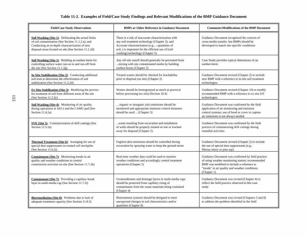
153
Table 11-2. Examples of Field/Case Study Findings and Relevant Modifications of the BMP Guidance Document
Field/Case Study Observations BMPs or Other Reference in Guidance Document Comments/Modifications of the BMP Document
Soil Washing (Site 1): Delineating the actual limitsof soil contamination (See Section 11.1.2.a); andConducting an in-depth characterization of newdisposal areas located on site (See Section 11.1.2d)
There is a risk of inaccurate characterization with Guidance Document recognized the concern ofany soil treatment technology (Chapter 2); and cross-media transfer, but BMPs should beAccurate characterization (e.g., ...quantities of developed to match site-specific conditionssoil..) is important for the efficient use of [soilwashing] technology (Chapter 5)
Soil Washing (Site 1): Building an earthen berm forcontrolling surface water run-on to and run-off fromthe site (See Section 11.1.2g)
Any off-site runoff should generally be prevented from Case Study provides typical dimensions of an...mixing with site contaminated media by building earthen bermearthen berms (Chapter 5)
In Situ Stabilization (Site 2): Conducting additionalsoil tests to determine the effectiveness of soilstabilization (See Section 11.2.2d)
Treated wastes should be checked for leachability Guidance Document revised (Chapter 2) to includeprior to disposal (on site) (Chapter 2) new BMP with a reference to in situ soil treatment
technologies
Ex Situ Stabilization (Site 3): Modifying the processfor treatment of soil from different areas of the site(See Section 11.3.2e)
Wastes should be homogenized as much as practical Guidance Document revised (Chapter 10) to modifybefore processing (ex situ) (Section 10.4) recommended BMP with a reference to ex situ S/S
technologies
Soil Washing (Site 4): Monitoring of air qualityduring operations at AECs and the CAMU pad (SeeSection 11.4.2a)
... organic or inorganic (air) emissions should be Guidance Document was confirmed by the fieldmonitored and appropriate emission control measures application of air monitoring and emissionshould be used ... (Chapter 5) control systems; use of hood or cover to capture
air emissions is not always needed
SVE (Site 5): Containerization of drill cuttings (SeeSection 11.5.2a)
...waste resulting from excavation and installation Guidance Document was confirmed by the fieldof wells should be properly treated on site or trucked practice of containerizing drill cuttings duringaway for disposal (Chapter 2) remedial activities
Thermal Treatment (Site 6): Arranging for use ofspecial dust suppressants on treated soil stockpiles(See Section 11.6.2i)
Fugitive dust emissions should be controlled during Guidance Document revised (Chapter 2) to includeexcavation by spraying water to keep the ground moist the use of special dust suppressants (e.g.,
fibrous slurry or pine sap)
Containment (Site 7): Monitoring trends in airquality and weather conditions to controlconstruction activities on site (See Section 11.7.2b)
Real-time weather data could be used to monitor Guidance Document was confirmed by field practiceweather conditions and accordingly control treatment of using weather monitoring station; recommendedoperations (Chapter 2) BMP was modified to include a reference to
"trends" in air quality and weather conditions(Chapter 1)
Containment (Site 7): Providing a capillary breaklayer in multi-media cap (See Section 11.7.2i)
Geomembranes and drainage layers in multi-media caps Guidance Document was revised (Chapter 4) toshould be protected from capillary rising of reflect the field practice observed in this casecontaminants from the waste materials being contained study(Chapter 4)
Bioremediation (Site 8): Problems due to lack ofadequate treatment capacity (See Section 11.8.3)
Biotreatment systems should be designed to meet Guidance Document was revised (Chapters 2 and 8)unexpected changes in soil characteristics and/or to address the problem identified in the fieldquantities (Chapter 8)