Besam Swingmaster 900 Service and Installation Manual Install Manual.pdf · Besam Swingmaster® 900...
68
Besam Swingmaster ® 900 Service and Installation Manual Complies with ANSI/BHMA A156.10 standards for power operated pedestrian doors. UL325 & UL991 Listed US23-0583-51 1/31/2008
Transcript of Besam Swingmaster 900 Service and Installation Manual Install Manual.pdf · Besam Swingmaster® 900...
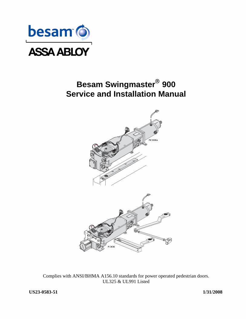
Besam Swingmaster® 900 Service and Installation Manual
Complies with ANSI/BHMA A156.10 standards for power operated pedestrian doors.UL325 & UL991 Listed
US23-0583-51 1/31/2008


Table of Contents UImportant InformationU............................................................................................... 1
UImportant Installation InstructionsU .............................................................................. 1 URadio and television receptionU .................................................................................... 1
UIntroductionU ............................................................................................................... 3 UHow The Swingmaster WorksU ..................................................................................... 3
UOpeningU ............................................................................................................... 3 UClosingU ................................................................................................................ 3
UImportant Safety InstructionsU ................................................................................... 4 UFunction Description of CircuitsU................................................................................... 4
UFunction of KillU ...................................................................................................... 4 UFunction of LocksU .................................................................................................. 4 UPush and GoU ......................................................................................................... 4 UPower FailureU........................................................................................................ 4
USafety FunctionsU ........................................................................................................ 5 UFunction of the Presence Impulse (Approach Side)U ........................................................ 5 UFunction of the Presence Detection (Swing Path Side)U .................................................... 5 UFunction of the OPDU .................................................................................................. 5 UPanic Function U.......................................................................................................... 5 USafety Functions with SensorsU .................................................................................... 5 UFunction of Door Positioning Device (Cam Set)U.............................................................. 5
UDoor/Operator HandingU ............................................................................................. 6 USpring Selection GuideU ............................................................................................... 7 UPart Identification & OptionsU ..................................................................................... 8
USwingmaster 900 Surface Mount – Side LoadU................................................................ 8 USwingmaster 900 Concealed Mount – Side LoadU ............................................................ 9 UArmsU .................................................................................................................... 10
UPushing ArmU ....................................................................................................... 10 UPull ArmU............................................................................................................. 11 UConcealed Arm: U .................................................................................................. 11 USpacer Kit:U ......................................................................................................... 11
UOptionsU .................................................................................................................... 12 UPush Plates:U........................................................................................................... 12 URemote Push Plates (RF)U ......................................................................................... 12 UControl Units and CablesU.......................................................................................... 12 USwitchesU ............................................................................................................... 13 ULabelsU ................................................................................................................... 13
UTypes of InstallationU ................................................................................................ 14 UGeneral Tips / Safety ConcernsU ................................................................................ 15 USummary InstallationU............................................................................................... 15 UFastening Requirements U .......................................................................................... 16 UTest EquipmentU ........................................................................................................ 16 UTools RequiredU ......................................................................................................... 16 UPre-installation AdjustmentsU.................................................................................... 17
UCam AdjustmentU..................................................................................................... 17 UChanging the Hand of the OperatorU ........................................................................... 17 UAdjustment of built-in mechanical full open door stopsU ................................................. 18
U(A) Left Hand Overhead ConcealedU ........................................................................ 18 U(B) Left Hand Surfaced AppliedU.............................................................................. 18 U(C) Right Hand Overhead Concealed and Surfaced AppliedU ........................................ 18 UCam Switch Harness DetailU ................................................................................... 19
UConcealed InstallationU ............................................................................................. 20 UInstallation for Center Pivot DoorsU........................................................................... 21

UInstallation of Side-Load Header and Operator in Installed FrameU ............................. 23 UInstallation of Side-Load Header and Operator in Uninstalled FrameU ........................ 23 UMounting the Bottom PivotU ....................................................................................... 23 UInstallation of Door LeafU .......................................................................................... 23 UMounting the bottom pivotU ....................................................................................... 24 UInstallation of Door LeafU .......................................................................................... 24
USurface Mount InstallationU ....................................................................................... 25 UModels U .................................................................................................................. 25 USurface Mount InstallationU ....................................................................................... 26 UArm Systems (Surface Applied)U ................................................................................ 27
USurface Mount Installation – PushU ........................................................................... 28 UPushing Arm System, (single) U................................................................................... 28 UPush Arm System (double)U...................................................................................... 29
USurface applied dual push.U.................................................................................... 29 UPull Arm System, (single)U ..................................................................................... 30 USurface applied double pullU ................................................................................... 31 USurface applied dual egressU .................................................................................. 32
UMounting the Arm SystemU ........................................................................................ 33 UPush Arm SystemU ................................................................................................... 33 UPull Arm SystemU ..................................................................................................... 33
UBottom Load InstallationU.......................................................................................... 34 UParts and installationU............................................................................................... 34 UBottom Load InstallationU.......................................................................................... 35
UElectrical Connections and AdjustmentsU................................................................... 36 UConnectionsU ........................................................................................................... 36 UPairs of Doors (2 – CU2 Controls Required)U ................................................................ 37 UAdjustmentsU .......................................................................................................... 38
UPotentiometersU ................................................................................................... 39 ULED Indications & Terminal DescriptionsU ................................................................. 40 UTerminal Descriptions U .......................................................................................... 41 UPlugs on the control boardU .................................................................................... 42 UInstallation of CUHubU ........................................................................................... 43
UANSI / BHMA A156.10U ............................................................................................. 44 USwinging Doors U ...................................................................................................... 44
U6. Guide RailsU ..................................................................................................... 44 U8. SensorsU.......................................................................................................... 45 U10. Entrapment ProtectionU .................................................................................... 47 U11. SignageU ........................................................................................................ 48 UAPPENDIX E-4 MAINTENANCE (NOT PART OF ANSI/BHMA 156.10)U ............................. 49
UTroubleshootingU ....................................................................................................... 50 UFrequently Asked QuestionsU..................................................................................... 52 UPlanned Maintenance ChecklistU ................................................................................ 53 USpare Parts U .............................................................................................................. 54 UWiring DiagramsU ...................................................................................................... 59
UCU2 Backward Compatibility with LO21BU .................................................................... 59

Besam Entrance Solutions 1 1/31/2008
0BImportant Information 28BImportant Installation Instructions
WARNING - To reduce the risk of server injury or death, material damage and malfunction of the product, the instructions contained in this manual must be strictly observed during installation, adjustment, repairs, service, etc. Only Besam trained technicians should be allowed to carry out these operations.
29BRadio and television reception This equipment generates and uses radio frequency energy and if not installed and used properly in strict accordance with the manufacturer's instructions, may cause interference to radio and television reception. It has been designed to comply with the emission limits in accordance with EN 50081-1 (US market FCC Part 15), which are designed to provide reasonable protection against such interference in a residential installation. However, there is no guarantee that interference will not occur in a particular installation. If this equipment does cause interference to radio or television reception, which can be determined by turning the equipment off and on, the user is encouraged to try to correct the interference by one or more of the following measures:
• Re-orient the receiving antenna. • Relocate the receiver with respect to the equipment. • Move the receiver away from the equipment. • Plug the receiver into a different outlet so that equipment and receiver are on different branch
circuits.
Plug the receiver into a different outlet so that equipment and receiver are on different branch circuits.
If necessary, the user should consult the dealer or an experienced radio/television technician for additional suggestions.
Note! Besam follows a policy of advancements in development.
Instructions, design, specifications and illustrations, which are contained in this manual, are not binding. Rights are reserved for changes without previous notice.
Note! The glazing material in all unframed swing doors shall comply with the requirements in the Performance Specifications and Methods of Test for Safety Glazing Material Used in Buildings, ANSI Z97.1. Glazing materials for other pedestrian doors shall also comply with ANSI Z97.1, except that single strength or heavier glass may be used for those portions of doors involving a glazed area of less than 1sqf and having no dimension greater than 18”.

Besam Entrance Solutions 2 1/31/2008
Technical Specifications
Power supply:
Power consumption:
Auxiliary voltage:
Control fuse:
Control breaker:
120 V AC ±10 %, 60 Hz
max. 4 amps
18 V AC/DC, max. 1 Amp
2 Amp
4 Amp
Maximum door weight: 220 lb/100 kg for door leaf width max.-55”
Hold open time:
Ambient temperature:
0-60 seconds
-20°F (-29°C) and 160°F (71°C)
* Note: Building codes may not permit doors wider than 48” (1219 mm).
Please refer to your local AHJ (Authority Having Jurisdiction) for clarification.

Besam Entrance Solutions 3 1/31/2008
1BIntroduction This manual contains the necessary details and instructions for the installation, maintenance and service of the Besam swing door operator, Swingmaster® 900, a universal electro-mechanical operator suitable for various external and internal swing doors. The Swingmaster 900 overhead concealed is designed to be integrated in the complete jamb and door assembly. It is self-supporting and suitable for single or double doors fitted with center pivots. The Swingmaster 900 surface mount can be mounted on either side of the door header for pull or push operation, and is suitable for single or double doors fitted with butt hinges, offset or center pivots. The Besam Swingmaster 900 swing door operator can be combined with a full range of sensor products providing swing door safety.
30BHow The Swingmaster Works The Swingmaster uses a DC motor and gear-reduction system (the operator) to drive an arm system that opens the door. Closing power is provided by coil spring. An electronic control unit uses a cam door positioning system to control the door’s movement. Note: One control unit required per operator.
69BOpening When the control unit receives an opening signal, the door is opened at the Swingmaster’s high speed. Before the door is fully open, it slows to low speed. The motor stops when the operator reaches the full open stop. The motor holds the open position. If the door is obstructed while opening it should stop (adjust the HLD potentiometer accordingly). Once all signals (or similar wording) have cleared and the time delay has expired the door will reverse to the closed position. The force that it takes to stop an opening door is adjustable from 12 to 25lbs depending on door widths and speeds.
70BClosing When the time delay expires, the Swingmaster will close the door automatically using spring force only, and with the motor acting as a brake. The door will slow to low speed before it reaches the fully closed position. The door is kept fully closed by spring force.

Besam Entrance Solutions 4 1/31/2008
2BImportant Safety Instructions WARNING – To reduce the risk of severe injury or death, all instruction and installation of safety equipment must be performed in accordance to ANSI 156.10 for pedestrian usage.
31BFunction Description of Circuits
71BFunction of Kill If the kill circuit is closed on the master or slave control, the control(s) will ignore all signals and immediately close door(s) at normal speed.
72BFunction of Locks The control has an available output of 18 VAC/DC for external locks and lock modules. This output will require an add on module by others to interface the external lock.
73BPush and Go Initiates the automation of the door by way of the act of “pushing the door”. Additional after market hardware is required.
74BPower Failure After a power failure there is a warm up safety feature of 5 seconds. This allows the time for the safety system to power up and observe the surrounding conditions.
Besam Entrance Solutions 5 1/31/2008
3BSafety Functions 32BFunction of the Presence Impulse (Approach Side)
When coordinated through the CUHub, a sensor mounted to the approach side of a door will only be active when the door is in motion. Once the door is closed, the sensor is ignored. When the CUHub is not used, this feature can also be obtained by utilizing TB1: 8 or 9 depending on brand or model of sensor used.
33BFunction of the Presence Detection (Swing Path Side) When a sensor that is mounted on the swing side of a door detects an object, it will send a command to the control to either stop or creep open. When using the CUHub this feature is active upon impulse and is ignored once the door reaches back check. If the control has received a short signal to stop or creep open and there is still time delay left on the control, the door will continue to open if the object has cleared. If the time delay has expired, the door will close after all other signals have cleared.
Note: When installed as a pair, the presence detection signal will stop or creep open both doors.
34BFunction of the OPD When an OPD (Overhead Presence Detector) sensor is mounted above the door on the swing side, it will either keep a door in the open position, keep the door in the closed position or prevent a closing door from reopening after a safety beam, mounted at the end of the guide rails, is blocked.
35BPanic Function Center pivoted doors can be pushed in the opposite direction for panic egress. If one door of a pair is pushed in the panic direction, both doors will be disabled until the door’s internal spring has slowly returned it to the closed position. Once closed, the doors will return to normal operation after the 5-second safety delay has expired.
36BSafety Functions with Sensors For automated pedestrian doors, safety sensors are required to meet ANSI 156.10.
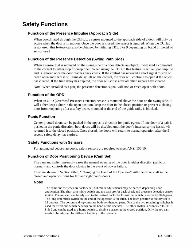
37BFunction of Door Positioning Device (Cam Set) The cam and switch assembly eases the manual opening of the door in either direction (panic or normal), and controls the door closing in the event of power failure.
They are shown in Section titled, “Changing the Hand of the Operator” with the drive shaft in the closed and open positions for left and right hands doors.
Note! The cams and switches are factory set, but minor adjustments may be needed depending upon application. The short arm micro switch and top cam are for back check and presence detection sensor inhibit. The top cam can be adjusted to the desired back check position, which is normally 80 degrees. The long arm micro switch on the end of the operator is for latch. The latch position is factory set to 12 degrees. The bottom and top cams are both non-handed parts. One of the two remaining switches is used for break out, which depends on the hand of the operator. The other switch is connected to TB1: 8 & 9 and can be used as a home switch to disable a sensor at the closed position. Only the top cam needs to be adjusted for different handing of the operator.
Besam Entrance Solutions 6 1/31/2008
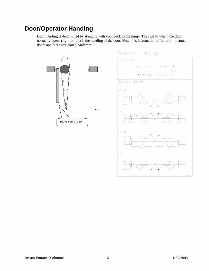
4BDoor/Operator Handing Door handing is determined by standing with your back to the hinge. The side to which the door normally opens (right or left) is the handing of the door. Note, this information differs from manual doors and there associated hardware.
Right Hand Door
Besam Entrance Solutions 7 1/31/2008
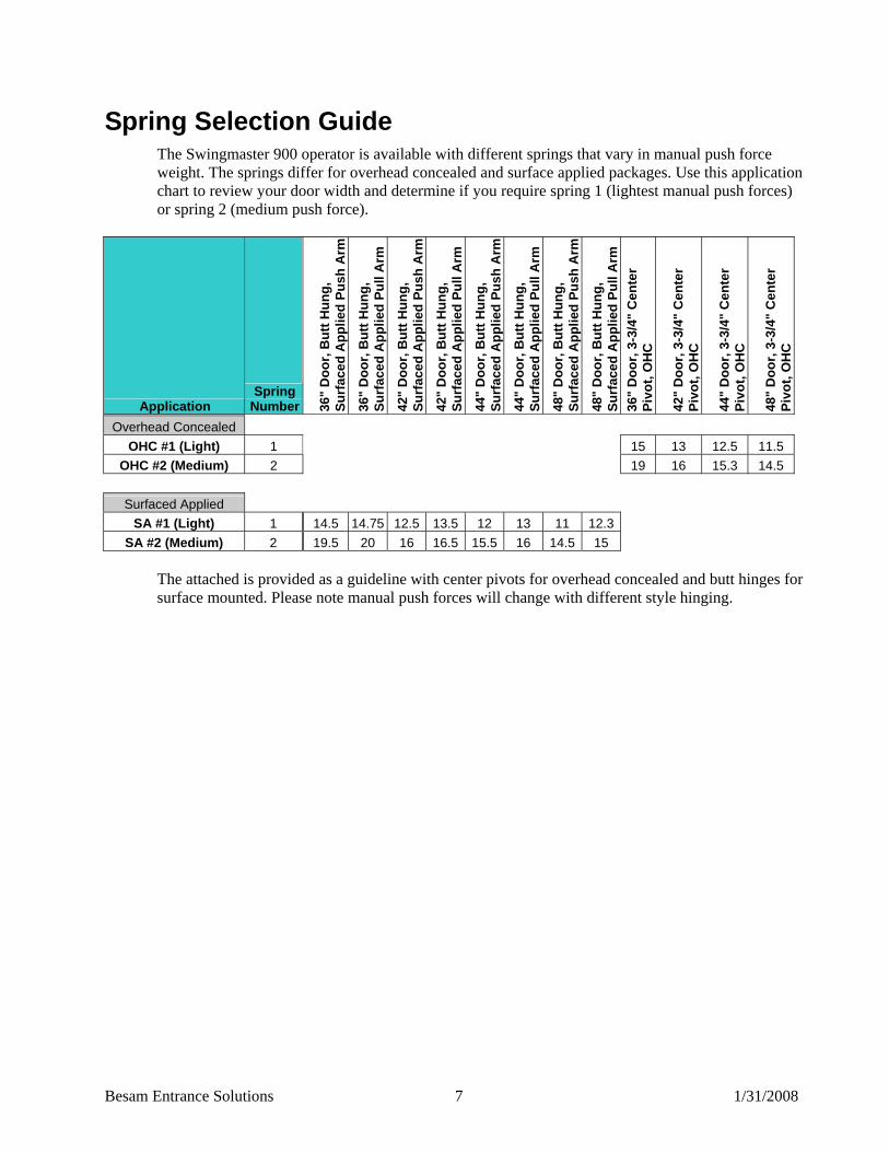
5BSpring Selection Guide The Swingmaster 900 operator is available with different springs that vary in manual push force weight. The springs differ for overhead concealed and surface applied packages. Use this application chart to review your door width and determine if you require spring 1 (lightest manual push forces) or spring 2 (medium push force).
Application Spring
Number 36"
Doo
r, B
utt H
ung,
Su
rfac
ed A
pplie
d Pu
sh A
rm
36"
Doo
r, B
utt H
ung,
Su
rfac
ed A
pplie
d Pu
ll A
rm
42"
Doo
r, B
utt H
ung,
Su
rfac
ed A
pplie
d Pu
sh A
rm
42"
Doo
r, B
utt H
ung,
Su
rfac
ed A
pplie
d Pu
ll A
rm
44"
Doo
r, B
utt H
ung,
Su
rfac
ed A
pplie
d Pu
sh A
rm
44"
Doo
r, B
utt H
ung,
Su
rfac
ed A
pplie
d Pu
ll A
rm
48"
Doo
r, B
utt H
ung,
Su
rfac
ed A
pplie
d Pu
sh A
rm
48"
Doo
r, B
utt H
ung,
Su
rfac
ed A
pplie
d Pu
ll A
rm
36"
Doo
r, 3-
3/4"
Cen
ter
Pivo
t, O
HC
42"
Doo
r, 3-
3/4"
Cen
ter
Pivo
t, O
HC
44"
Doo
r, 3-
3/4"
Cen
ter
Pivo
t, O
HC
48"
Doo
r, 3-
3/4"
Cen
ter
Pivo
t, O
HC
Overhead Concealed OHC #1 (Light) 1 15 13 12.5 11.5
OHC #2 (Medium) 2 19 16 15.3 14.5
Surfaced Applied SA #1 (Light) 1 14.5 14.75 12.5 13.5 12 13 11 12.3
SA #2 (Medium) 2 19.5 20 16 16.5 15.5 16 14.5 15 The attached is provided as a guideline with center pivots for overhead concealed and butt hinges for surface mounted. Please note manual push forces will change with different style hinging.

Besam Entrance Solutions 8 1/31/2008
6BPart Identification & Options 38BSwingmaster 900 Surface Mount – Side Load
PARTS LIST
(1) Header
(2) Cover
(3) Long Center Panel
(4) Short Center Panel
(5) End Caps (2)
(6) Header Mounting Holes (4)
(7) Mounting Bolts (4)
(8) Cable Holes (4)
(9) Ground Bolt (1)
(10) Jamb / Wall (Surface) (2)
(11) CU2 Control Unit
(12) Operator
(13) Cams and Switches
(14) Harness
(15) Motor
(16) Spindle Lock Screw
(17) Drive Spindle
(18) Operator Mount, Motor
(19) Operator Mount, Hinge
(20) Support Bracket (Surface)
(21) Clamp Plate (Surface)
(22) Label
(23) Controller Strap
Besam Entrance Solutions 9 1/31/2008
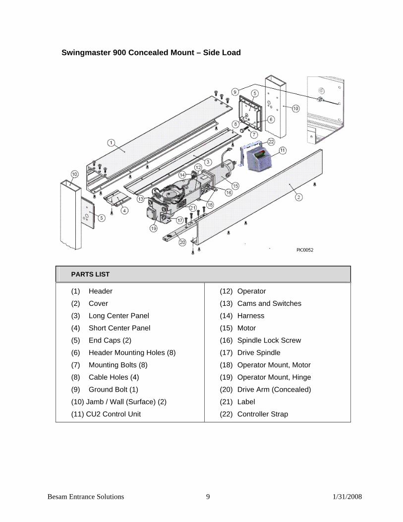
39B Swingmaster 900 Concealed Mount – Side Load
PARTS LIST
(1) Header
(2) Cover
(3) Long Center Panel
(4) Short Center Panel
(5) End Caps (2)
(6) Header Mounting Holes (8)
(7) Mounting Bolts (8)
(8) Cable Holes (4)
(9) Ground Bolt (1)
(10) Jamb / Wall (Surface) (2)
(11) CU2 Control Unit
(12) Operator
(13) Cams and Switches
(14) Harness
(15) Motor
(16) Spindle Lock Screw
(17) Drive Spindle
(18) Operator Mount, Motor
(19) Operator Mount, Hinge
(20) Drive Arm (Concealed)
(21) Label
(22) Controller Strap

Besam Entrance Solutions 10 1/31/2008
40BArms The Swingmaster 900 can be equipped with three kinds of arms: a push arm that pushes the door open, a pull arm that pulls the door open, and a concealed arm that swings the door in either direction.
Note: Only one arm is required per operator.
75BPushing Arm The push arm is used when installing the Swingmaster on the opposite side of the wall from the direction in which the door opens.
P/N Reveal Color
30-06-201 4 1/8” – 6” Clear
30-06-112 5” – 6” Black
30-06-110 6 1/8” – 8” Clear
30-06-113 7” – 8” Black
30-06-107 8 1/8” – 10” Clear
30-06-114 9” – 10” Black
30-06-109 10 1/8” – 12” Clear
30-06-115 11” – 12” Black
Besam Entrance Solutions 11 1/31/2008
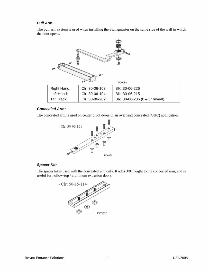
76BPull Arm The pull arm system is used when installing the Swingmaster on the same side of the wall in which the door opens.
Right Hand: Left Hand: 14” Track:
Clr: 30-06-103 Clr: 30-06-104 Clr: 30-06-202
Blk: 30-06-226 Blk: 30-06-215 Blk: 30-06-236 (0 – 5” reveal)
77BConcealed Arm: The concealed arm is used on center pivot doors in an overhead concealed (OHC) application.
78BSpacer Kit: The spacer kit is used with the concealed arm only. It adds 3/8” height to the concealed arm, and is useful for hollow-top / aluminum extrusion doors.

Besam Entrance Solutions 12 1/31/2008
7BOptions 41BPush Plates:
Push Plates come in three shapes (Round, Square and Narrow), and in normal or remote switch configuration.
P/N: US02-0153-02
P/N: US02-0153-04
P/N: 75-02-100
P/N: 75-02-104
Square: “Push To Open”
Square: Blank
Round: “Push To Open”
Round: Blank
P/N: 75-02-281
P/N: 75-21-002
Narrow: “Push To Open”
Narrow: Blank
42BRemote Push Plates (RF)
P/N: 75-02-269
P/N: 75-02-273
P/N: 75-02-271
Narrow: “Push To Open”
Round: “Push To Open”
Remote Receiver
43BControl Units and Cables
P/N: US02-0583-01
P/N: US02-0583-02
P/N: US02-0583-14
P/N: US02-0583-04
P/N: US02-0583-05
Swingmaster 900 CU2 Control
Swingmaster 900 CUHub
Swingmaster 900 CU2 Sync Cable for pairs
Swingmaster 900 Micro Switch Cable
Swingmaster 900 CU2 to CUHub Cable
Besam Entrance Solutions 13 1/31/2008
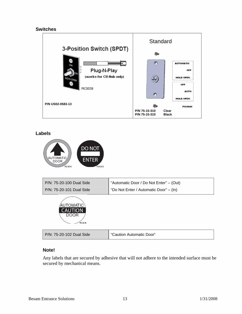
44BSwitches
P/N US02-0583-13
Standard
P/N 75-15-310 Clear P/N 75-15-310 Black
45BLabels
P/N: 75-20-100 Dual Side
P/N: 75-20-101 Dual Side
“Automatic Door / Do Not Enter” – (Out)
“Do Not Enter / Automatic Door” – (In)
P/N: 75-20-102 Dual Side “Caution Automatic Door“
Note! Any labels that are secured by adhesive that will not adhere to the intended surface must be secured by mechanical means.
Besam Entrance Solutions 14 1/31/2008
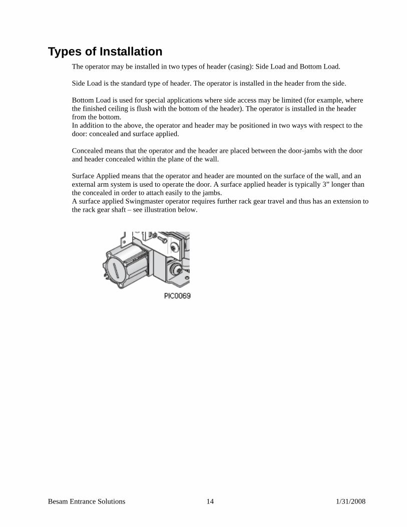
8BTypes of Installation The operator may be installed in two types of header (casing): Side Load and Bottom Load. Side Load is the standard type of header. The operator is installed in the header from the side. Bottom Load is used for special applications where side access may be limited (for example, where the finished ceiling is flush with the bottom of the header). The operator is installed in the header from the bottom. In addition to the above, the operator and header may be positioned in two ways with respect to the door: concealed and surface applied. Concealed means that the operator and the header are placed between the door-jambs with the door and header concealed within the plane of the wall. Surface Applied means that the operator and header are mounted on the surface of the wall, and an external arm system is used to operate the door. A surface applied header is typically 3” longer than the concealed in order to attach easily to the jambs. A surface applied Swingmaster operator requires further rack gear travel and thus has an extension to the rack gear shaft – see illustration below.

Besam Entrance Solutions 15 1/31/2008
9BGeneral Tips / Safety Concerns • For enhanced security and vandalism protection, mount the operator access to the interior of the
building whenever possible. • Ensure that the power is off before installing. • Insure that the door leaf and the wall are properly reinforced at the installation points. • Inspect the door hinges before installation to ensure that they are in good repair.
10BSummary Installation This is only a summary of the installation process. See the rest of this manual for detailed information.
1. Establish installation height.
2. For surface applied installations, locate header horizontally above door so that the centerline of spindle to centerline of hinge dimension is correct.
3. Install the header.
4. Mount the operator.
5. Install the control unit so that the PC board is facing the removable access cover.
6. Attached all ground cables to ground bolt. (Reference section titled, “Part Identification & Options, for ground bolt location.)
7. For surface applied, attach the arm shoe to the door. For concealed installations, mount drive arm to shaft.
8. For surface applied installations, mount the rest of the drive arm. For concealed installations, mount/hang the door.
9. Complete all electrical connections to other operators or optional equipment.
10. Adjust the control unit for optimal and safe performance, in accordance with ANSI/BHMA A156.10 specifications for pedestrian applications.
11. Apply safety signage to the door(s).
12. Train facility manager in proper product operation.
13. Explain to the facility manager, the daily safety checklist described in the owner’s manual, and leave a copy of the owner’s manual with the facility manager.

Besam Entrance Solutions 16 1/31/2008
11BFastening Requirements Base door/wall material Minimum anchor / bolt requirement *
Steel 3/16” (20.63 mm) **
Aluminum ¼” (6.35 mm)**
Reinforced concrete Min. 2” (50.8 mm) from the underside
Wood 2” (50.8 mm)
Brick wall Expansion-shell bolt, min. ¼” x 3 ½” (6.35 x 88.9 mm), min. 2” (50.8 mm) from the underside
*Besam minimum recommended requirements. Building codes may give different specifications. ** Thinner wall profiles must be reinforced with Riv-Nuts.
12BTest Equipment • Stopwatch • Force gauge 50 lb (22.7 kg) force range) • Multimeter
13BTools Required • Set of box end wrenches • Spirit Level • Tape rule • Power drill and set of drill bits • Metric (MM) and Standard (SAE) Allen head • Center punch • #2 & #3 Phillips screwdriver • Flat blade screwdriver (small/medium/large) • Wire stripper • Pencil • Torque wrench /w/ metric Allen sockets • Additional mounting hardware (not supplied – see recommendations above) • Silicone sealant • Plumb bob • US23-0583-09 SwingMaster 900 Service and Installation Manual

Besam Entrance Solutions 17 1/31/2008
14BPre-installation Adjustments 46BCam Adjustment
The bottom cam and its two switches (Panic & Home Switch) are factory set at the home position.
1. The latch switch is factory set on the same cam to switch at 10-12 degrees from the closed position. If more or less latch is needed bend the switch arm slightly away from the cam for more latch, towards the cam fore less.
2. If pre-load is applied, or the centering of the arm has been adjusted, loosen the bolt in the center of the cams with a 7/16” wrench and adjust the bottom cam so that the home and panic switches are not being activated at the door home (closed) position. Re-secure bolt when finished.
3. The top cam is factory set as either a right hand or left hand and switches at 80 degrees.
4. If the back check position needs adjustment, loosen the bolt in the center of the cams with a 7/16” wrench and rotate the top cam to the desired position. Re-secure bolt.
47BChanging the Hand of the Operator 1. With the door and operator at the home position, loosen the top 7/16” bolt and turn the top
cam aligning the handing mark to the hand indicated on the bottom cam.
2. Re-secure 7/16” bolt and check for proper functionality.
(1) Back Check Switch
(2) Bottom Cam
(3) Break Out Switch
(4) Latch Switch
(5) Top Cam
(6) Home Switch

Besam Entrance Solutions 18 1/31/2008
(1) Back Check Switch
(2) Bottom Cam
(3) Break Out Switch
(4) Latch Switch
(5) Top Cam
(6) Home Switch
48BAdjustment of built-in mechanical full open door stops The built-in mechanical full open stops are factory set to 90 degrees. If needed, the full open stops can be adjusted as shown below.
79B(A) Left Hand Overhead Concealed Remove the square end cap (1) to access the LH adjustment screw. Turn the screw out to decrease the opening angle, in to increase. Reinstall square cap.
80B(B) Left Hand Surfaced Applied Loosen set screw (2).
Adjust end cap screw (3) for opening angle Screw out to increase, and in to decrease. If additional adjustment is needed, remove the end cap and adjust the internal screw as per step “A”. Replace end cap.
81B(C) Right Hand Overhead Concealed and Surfaced Applied Loosen door stop lock nut (4)
Adjust bolt (5) for opening angle. Screw out to increase, and in to decrease.
Note!
(A) (B) (C)
Besam Entrance Solutions 19 1/31/2008
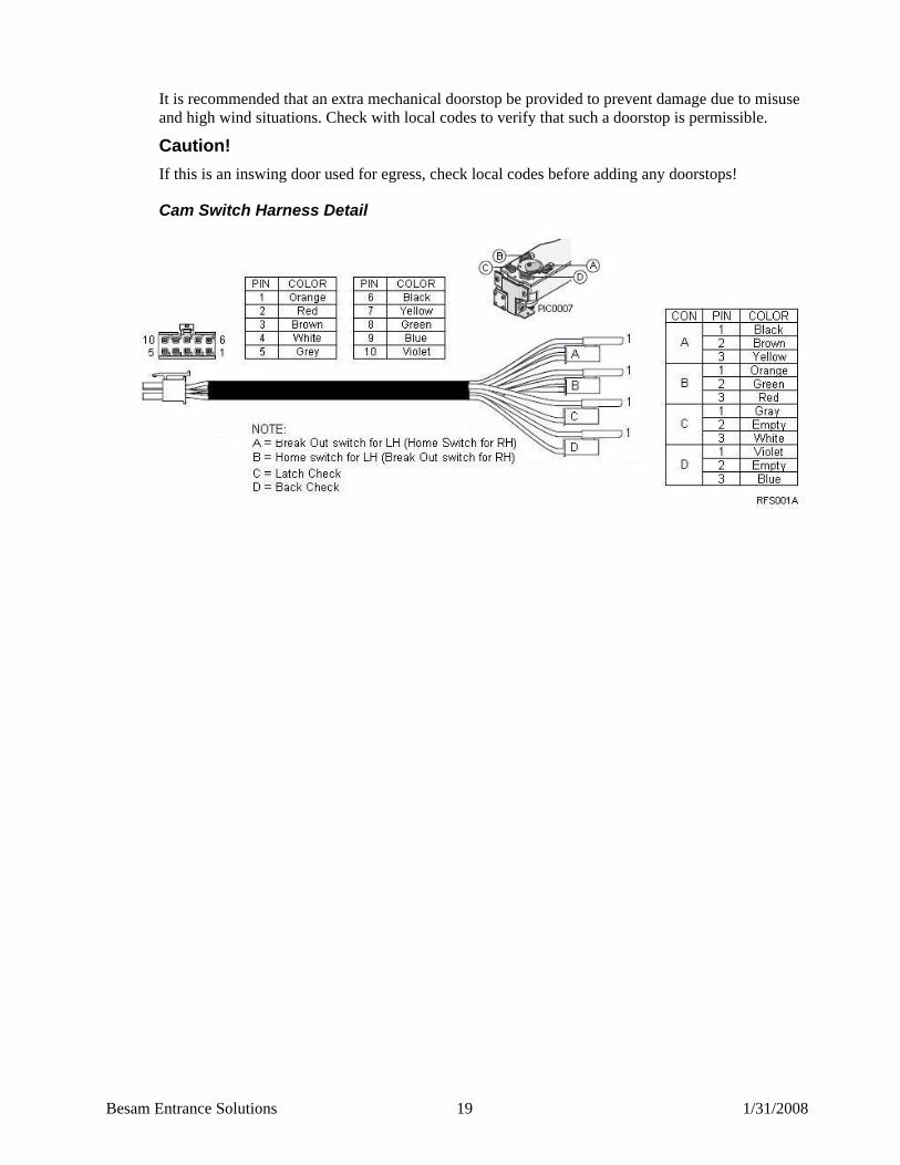
It is recommended that an extra mechanical doorstop be provided to prevent damage due to misuse and high wind situations. Check with local codes to verify that such a doorstop is permissible.
Caution! If this is an inswing door used for egress, check local codes before adding any doorstops!
82BCam Switch Harness Detail
Besam Entrance Solutions 20 1/31/2008
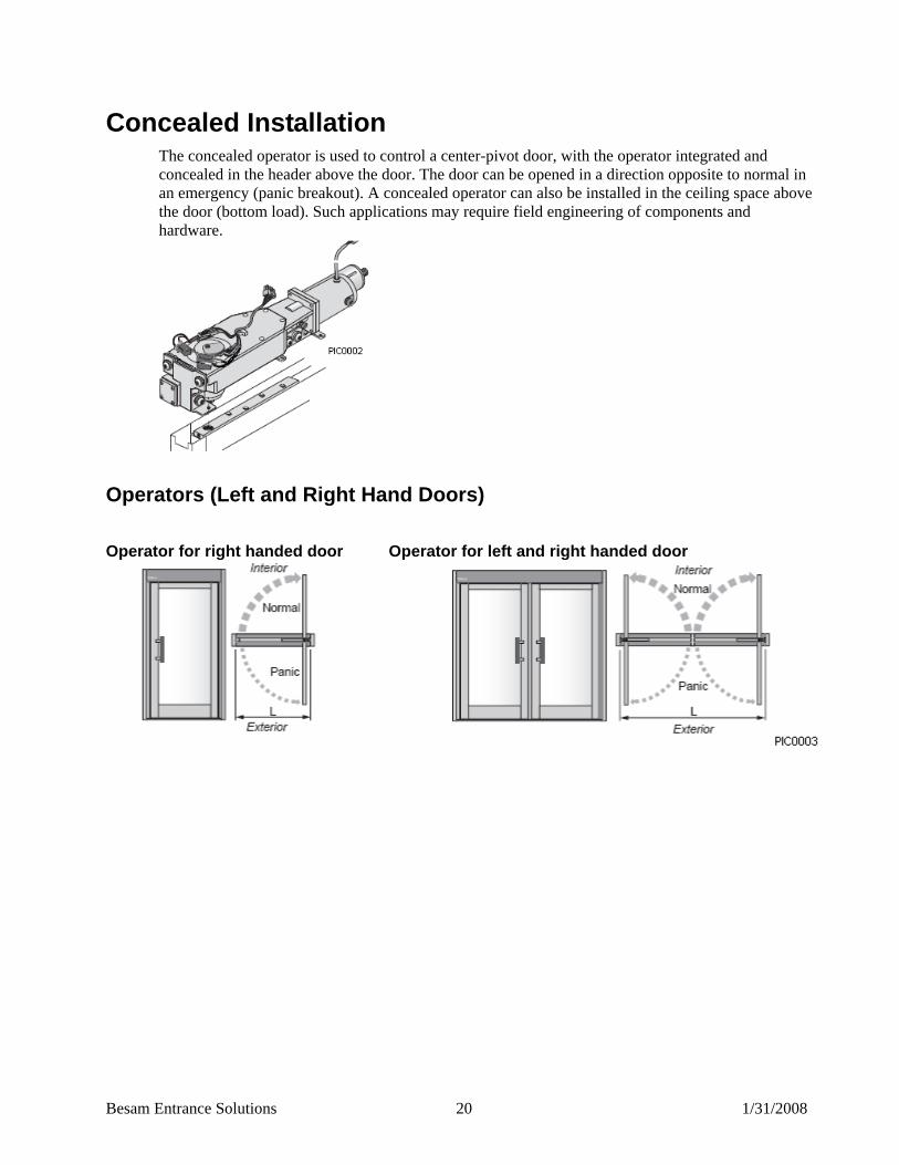
15BConcealed Installation The concealed operator is used to control a center-pivot door, with the operator integrated and concealed in the header above the door. The door can be opened in a direction opposite to normal in an emergency (panic breakout). A concealed operator can also be installed in the ceiling space above the door (bottom load). Such applications may require field engineering of components and hardware.
Operators (Left and Right Hand Doors)
Operator for right handed door Operator for left and right handed door
Besam Entrance Solutions 21 1/31/2008
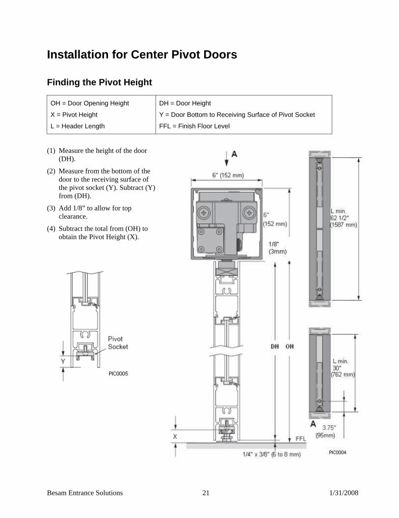
16BInstallation for Center Pivot Doors
Finding the Pivot Height
OH = Door Opening Height
X = Pivot Height
L = Header Length
DH = Door Height
Y = Door Bottom to Receiving Surface of Pivot Socket
FFL = Finish Floor Level
(1) Measure the height of the door (DH).
(2) Measure from the bottom of the door to the receiving surface of the pivot socket (Y). Subtract (Y) from (DH).
(3) Add 1/8” to allow for top clearance.
(4) Subtract the total from (OH) to obtain the Pivot Height (X).
Besam Entrance Solutions 22 1/31/2008
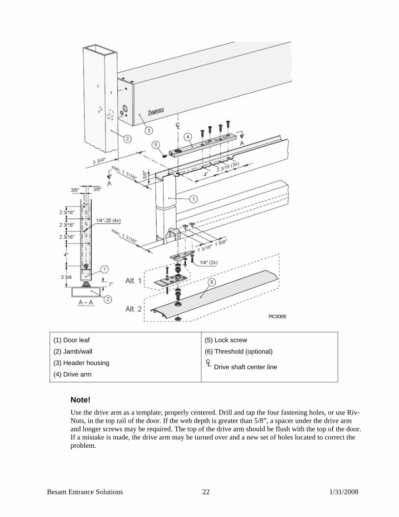
(1) Door leaf
(2) Jamb/wall
(3) Header housing
(4) Drive arm
(5) Lock screw
(6) Threshold (optional)
Drive shaft center line
Note! Use the drive arm as a template, properly centered. Drill and tap the four fastening holes, or use Riv-Nuts, in the top rail of the door. If the web depth is greater than 5/8”, a spacer under the drive arm and longer screws may be required. The top of the drive arm should be flush with the top of the door. If a mistake is made, the drive arm may be turned over and a new set of holes located to correct the problem.

Besam Entrance Solutions 23 1/31/2008
49BInstallation of Side-Load Header and Operator in UInstalled UFrame 1. Establish the door opening height (OH) and the correct length (L) of the header (see page 20).
2. Measuring from the highest point on the floor, mark the door opening height on one door jamb.
3. Use a spirit level and transfer the mark to the opposite jamb.
4. Dismantle the casing, separating the header, cover, short and long center panels, and end caps (see page 8).
5. Use provided templates, or use end caps as templates, and drill appropriate header mounting holes and cable inlets.
Note! The cables can enter the header from the hinge/pivot side or from the strike side. Try to bring all wiring in at the strike side because of the tight conditions between the operator and end cap.
6. Install the end caps using appropriate screws, or Riv-Nuts if required.
7. Install the header onto the end caps.
8. Install the short center panel to the header/end cap with the outer screws, on the right or left side depending on the hand of door.
9. Install the long center panel.
10. Install the operator and secure it to the header with three screws on the side opposite the cover. The other three screws holding the operator will be installed with the cover.
50BInstallation of Side-Load Header and Operator in Uninstalled Frame Attach end caps and header to jambs as described above (steps 1-5). Tilt header/jamb assembly up into rough opening in wall. Level header and plumb jambs, shimming as needed. Fasten jambs, then proceed to step 10 above. Details will vary widely according to the nature of the installation site.
51BMounting the Bottom Pivot Prepare and install the bottom pivot (reference section titled, “Finding the Pivot Height”). The bottom pivot can be installed in two ways:
Alt 1: With the base plate/bearing placed directly on the floor. The distance 3.75”/95 mm to the pivot centerline is obtained if the base plate is placed against the vertical jamb/wall.
Alt 2: With the bearing installed directly into the threshold. Make sure that the centerline of the bottom pivot and the centerline of the drive shaft are aligned.
Tip Use plumb bob.
52BInstallation of Door Leaf The door leaf must be prepared for the drive arm and bottom pivot per instructions (reference section titled, “Finding the Pivot Height” – see the second graphic).

Besam Entrance Solutions 24 1/31/2008
53BMounting the bottom pivot Prepare and install the bottom pivot (reference section titled, “Finding the Pivot Height”). The bottom pivot can be installed in two ways:
Alt 1: With the base plate/bearing placed directly on the floor. The distance 3.75” (95 mm) to the pivot centerline is obtained if the base plate is placed against the vertical jamb/wall.
Alt 2: With the bearing installed directly into the threshold. Make sure that the centerline of the bottom pivot and the centerline of the drive shaft are aligned.
Tip Use plumb bob.
54BInstallation of Door Leaf The door leaf must be prepared for the drive arm and bottom pivot per instructions on page 20.
Note! Step 5 below is critical. The door must be allowed to self-adjust to the bottom pivot.
1. Adjust the bottom pivot using instructions found in section titled, “Finding the Pivot Height” – 1st page).
2. Fit the drive arm to the operator drive shaft in line with the closed position for the door (0-position), and temporarily fix it with the drive arm set screw. Give a constant impulse, let the arm open to 90° and lock it in this position with the spindle lock screw.
Caution The OHC arm without the door will open and close with great force, keep hands and face away from arm during these steps.
3. With the drive arm still attached to the operator shaft and the bottom pivot set in place, slide the door in from the hinge and over the bottom pivot and guide the drive arm into the top web of the door.
4. Move the door in until the screw holes in the door line up with the holes in the drive arm and install the four screws through the arm to connect it to the top of the door.
5. Loosen the drive arm set screw and allow the arm and door to settle against the bottom pivot.
6. Check that the door has 1/8” (3 mm) maximum clearance at top and does not interfere with the bottom pivot plate. Remove the door and adjust the bottom pivot if necessary.
7. Tighten the four screws in the drive arm/door and then re-tighten the set screw in the drive arm.
8. Release the spindle lock screw and the constant impulse and allow the door to close.
Besam Entrance Solutions 25 1/31/2008
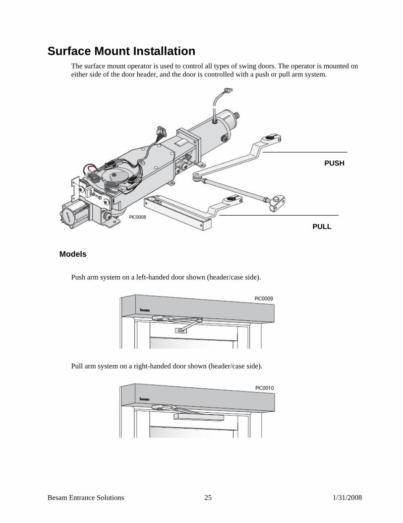
17BSurface Mount Installation The surface mount operator is used to control all types of swing doors. The operator is mounted on either side of the door header, and the door is controlled with a push or pull arm system.
55BModels
Push arm system on a left-handed door shown (header/case side).
Pull arm system on a right-handed door shown (header/case side).
PUSH
PULL
Besam Entrance Solutions 26 1/31/2008
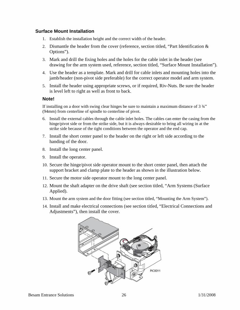
56BSurface Mount Installation 1. Establish the installation height and the correct width of the header.
2. Dismantle the header from the cover (reference, section titled, “Part Identification & Options”).
3. Mark and drill the fixing holes and the holes for the cable inlet in the header (see drawing for the arm system used, reference, section titled, “Surface Mount Installation”).
4. Use the header as a template. Mark and drill for cable inlets and mounting holes into the jamb/header (non-pivot side preferable) for the correct operator model and arm system.
5. Install the header using appropriate screws, or if required, Riv-Nuts. Be sure the header is level left to right as well as front to back.
Note! If installing on a door with swing clear hinges be sure to maintain a maximum distance of 3 ¾” (94mm) from centerline of spindle to centerline of pivot.
6. Install the external cables through the cable inlet holes. The cables can enter the casing from the hinge/pivot side or from the strike side, but it is always desirable to bring all wiring in at the strike side because of the tight conditions between the operator and the end cap.
7. Install the short center panel to the header on the right or left side according to the handing of the door.
8. Install the long center panel.
9. Install the operator.
10. Secure the hinge/pivot side operator mount to the short center panel, then attach the support bracket and clamp plate to the header as shown in the illustration below.
11. Secure the motor side operator mount to the long center panel.
12. Mount the shaft adapter on the drive shaft (see section titled, “Arm Systems (Surface Applied).
13. Mount the arm system and the door fitting (see section titled, “Mounting the Arm System”).
14. Install and make electrical connections (see section titled, “Electrical Connections and Adjustments”), then install the cover.
Besam Entrance Solutions 27 1/31/2008
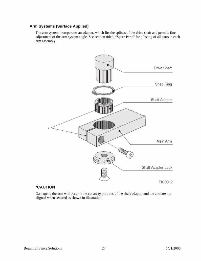
57BArm Systems (Surface Applied) The arm system incorporates an adapter, which fits the splines of the drive shaft and permits fine adjustment of the arm system angle. See section titled, “Spare Parts” for a listing of all parts in each arm assembly.
*CAUTION Damage to the arm will occur if the cut away portions of the shaft adaptor and the arm are not aligned when secured as shown in illustration.

Besam Entrance Solutions 28 1/31/2008
18BSurface Mount Installation – Push 58BPushing Arm System, (single)
The push arm system consists of a main arm, connecting rod, arm shoe and shaft adapter. If the reveal (A) (the distance from the wall surface to the door surface) is more than 4” (101 mm), a longer connecting rod is needed for the arm (reference, section titled, “Parts Identification & Options”). The maximum standard reveal is 12” (305 mm). All dimensions given here correspond to an opening angle of 90-100°. The operator is shown with push arm on a left-handed door (right-handed door mirror image).
PIC0073
(1) Clearance holes for 1/4” (6 mm) bolts and cable inlet to be drilled on site
(2) Offset pivot or butt hinge
(3) Main arm
(4) Connecting rod
(5) Arm shoe
Pivot/butt hinge centerline
Drive shaft centerline
Besam Entrance Solutions 29 1/31/2008
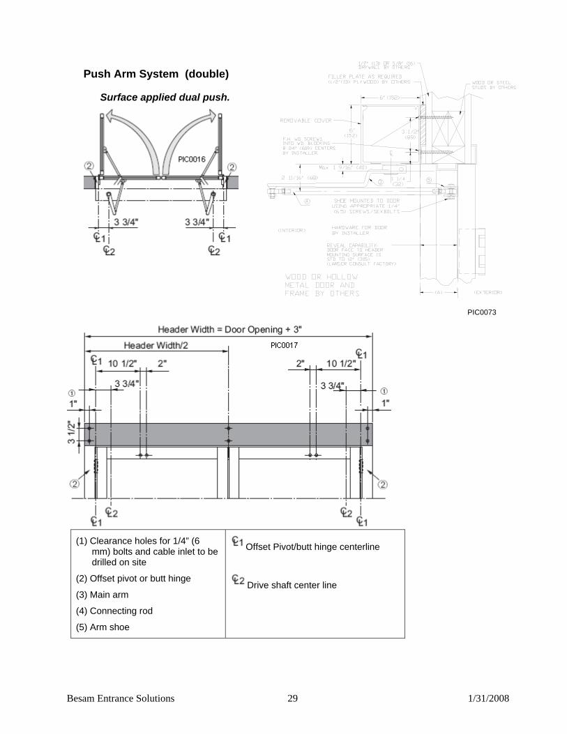
59BPush Arm System (double)
83BSurface applied dual push.
PIC0073
(1) Clearance holes for 1/4” (6 mm) bolts and cable inlet to be drilled on site
(2) Offset pivot or butt hinge
(3) Main arm
(4) Connecting rod
(5) Arm shoe
Offset Pivot/butt hinge centerline
Drive shaft center line
Besam Entrance Solutions 30 1/31/2008
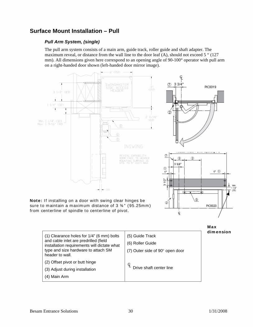
Surface Mount Installation – Pull
84BPull Arm System, (single) The pull arm system consists of a main arm, guide track, roller guide and shaft adapter. The maximum reveal, or distance from the wall line to the door leaf (A), should not exceed 5 “ (127 mm). All dimensions given here correspond to an opening angle of 90-100° operator with pull arm on a right-handed door shown (left-handed door mirror image).
Note: If installing on a door with swing clear hinges be sure to maintain a maximum distance of 3 ¾” (95.25mm) from centerline of spindle to centerline of pivot.
(1) Clearance holes for 1/4” (6 mm) bolts and cable inlet are predrilled (field installation requirements will dictate what type and size hardware to attach SM header to wall.
(2) Offset pivot or butt hinge
(3) Adjust during installation
(4) Main Arm
(5) Guide Track
(6) Roller Guide
(7) Outer side of 90° open door
Drive shaft center line
Max dimension
Besam Entrance Solutions 31 1/31/2008
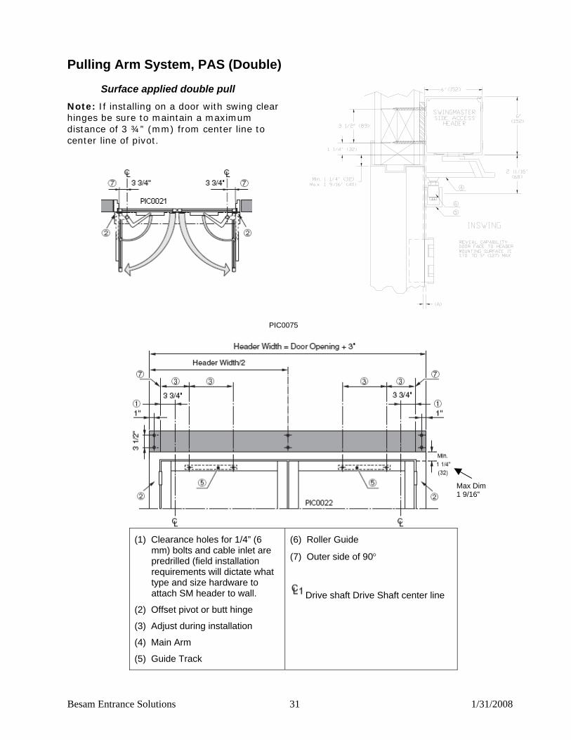
Pulling Arm System, PAS (Double)
85BSurface applied double pull Note: If installing on a door with swing clear hinges be sure to maintain a maximum distance of 3 ¾” (mm) from center line to center line of pivot.
PIC0075
(1) Clearance holes for 1/4” (6
mm) bolts and cable inlet are predrilled (field installation requirements will dictate what type and size hardware to attach SM header to wall.
(2) Offset pivot or butt hinge
(3) Adjust during installation
(4) Main Arm
(5) Guide Track
(6) Roller Guide
(7) Outer side of 90°
Drive shaft Drive Shaft center line
Max Dim 1 9/16”

Besam Entrance Solutions 32 1/31/2008
Push/Pull Arm System (double egress)
86BSurface applied dual egress Note: If installing on a door with swing clear hinges be sure to maintain a minimum distance of 3 ¾” (95.25mm) from a center line of spindle to center line of pivot.
PIC0074
(1) Clearance holes for 1/4” (6mm) bolts and cable inlet to be drilled on site
(2) Offset pivot or butt hinge
(3) Adjust during installation
(4) Outer side of 90°
CL Drive shaft center line
Offset pivot/butt hinge center line
Max Dim 1 9/16”
Besam Entrance Solutions 33 1/31/2008
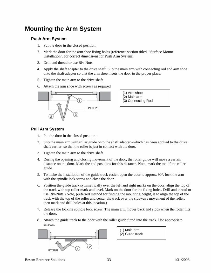
19BMounting the Arm System 60BPush Arm System
1. Put the door in the closed position.
2. Mark the door for the arm shoe fixing holes (reference section titled, “Surface Mount Installation”, for correct dimensions for Push Arm System).
3. Drill and thread or use Riv-Nuts.
4. Apply the shaft adapter to the drive shaft. Slip the main arm with connecting rod and arm shoe onto the shaft adapter so that the arm shoe meets the door in the proper place.
5. Tighten the main arm to the drive shaft.
6. Attach the arm shoe with screws as required.
61BPull Arm System 1. Put the door in the closed position.
2. Slip the main arm with roller guide onto the shaft adapter –which has been applied to the drive shaft earlier–so that the roller is just in contact with the door.
3. Tighten the main arm to the drive shaft.
4. During the opening and closing movement of the door, the roller guide will move a certain distance on the door. Mark the end positions for this distance. Note, mark the top of the roller guide.
5. To make the installation of the guide track easier, open the door to approx. 90°, lock the arm with the spindle lock screw and close the door.
6. Position the guide track symmetrically over the left and right marks on the door, align the top of the track with top roller mark and level. Mark on the door for the fixing holes. Drill and thread or use Riv-Nuts. (Note, preferred method for finding the mounting height, is to align the top of the track with the top of the roller and center the track over the sideways movement of the roller, then mark and drill holes at this location.)
7. Release the locking spindle lock screw. The main arm moves back and stops when the roller hits the door.
8. Attach the guide track to the door with the roller guide fitted into the track. Use appropriate screws.
(1) Arm shoe (2) Main arm (3) Connecting Rod
(1) Main arm (2) Guide track
Besam Entrance Solutions 34 1/31/2008
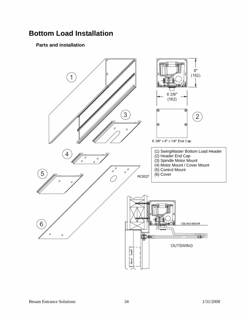
20BBottom Load Installation 62BParts and installation
(1) SwingMaster Bottom Load Header(2) Header End Cap (3) Spindle Motor Mount (4) Motor Mount / Cover Mount (5) Control Mount (6) Cover

Besam Entrance Solutions 35 1/31/2008
63BBottom Load Installation 1. The bottom load header and accessories are all field prepped per each application. Please refer to
drawings for all relevant templates and measurements. These drawings are supplied separately and will be shipped with the product.
2. Establish the door opening height (OH) and the correct length (L) of the header (reference section titled, “Installation for Center Pivot Doors”). Note: your header length will be less the thickness of your two end caps.
3. Prep the header with mounting holes to accommodate your particular application keeping in mind power access and structural strength.
4. Before installing the header, prep the bottom legs of the header for the spindle, motor and control mounts as per drawing.
5. Install the header using the measurements from the standard side load overhead concealed or surfaced mounted illustrations shown earlier in the manual. Note: the bottom load header is the same height as the standard 6”x 6” (152 x 152 mm) Swingmaster header, but keep in mind that the depth is 6 3/8” (162 mm) when centering the header on an overhead-concealed jamb. Use appropriate fasteners to attach header to opening.
6. All your door prep and spindle locations will be as illustrated earlier in the manual for the standard side load header.
7. Prep the spindle motor mount for either overhead concealed or surface applied as per drawing.
8. Prep the motor mount, the control mount, and the cover support plates as per drawings.
9. Prep the cover as per drawing
10. Install your spindle motor mount into either the far left or far right (depending on hand) of the header. For pairs or double egress install spindle mount at both ends.
11. Inspect your cams on top of your operator for the appropriate settings and install the operator by sitting the operator spindle end onto the spindle motor mount and slide the motor mount bracket under the operator and secure.
12. Install the control mount bracket and secure.
13. Install the CU2 control on top of the control mount bracket and secure.
14. Wire control, sensors and accessories securing the wires so that they don’t hang below header.
15. Make all adjustments to the control as per the appropriate ANSI standard and install header cover.
Besam Entrance Solutions 36 1/31/2008
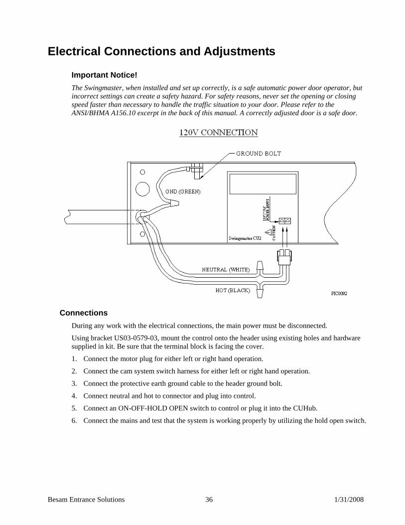
21BElectrical Connections and Adjustments Important Notice! The Swingmaster, when installed and set up correctly, is a safe automatic power door operator, but incorrect settings can create a safety hazard. For safety reasons, never set the opening or closing speed faster than necessary to handle the traffic situation to your door. Please refer to the ANSI/BHMA A156.10 excerpt in the back of this manual. A correctly adjusted door is a safe door.
64BConnections During any work with the electrical connections, the main power must be disconnected.
Using bracket US03-0579-03, mount the control onto the header using existing holes and hardware supplied in kit. Be sure that the terminal block is facing the cover.
1. Connect the motor plug for either left or right hand operation.
2. Connect the cam system switch harness for either left or right hand operation.
3. Connect the protective earth ground cable to the header ground bolt.
4. Connect neutral and hot to connector and plug into control.
5. Connect an ON-OFF-HOLD OPEN switch to control or plug it into the CUHub.
6. Connect the mains and test that the system is working properly by utilizing the hold open switch.
Besam Entrance Solutions 37 1/31/2008
65BPairs of Doors (2 – CU2 Controls Required) In this type of installation, both doors are activated through the master control and swing to the open position simultaneously. One CU2 control unit is always required per operator. When using a CUHub, only one CUHub is required for a single or pair of operators.
• Synchronizing is made through a 4-pole plug and play cable, connected to J2. • Connect opening impulses, OPD and presence and electro-mechanical locking devices to the
master control. Connect door-mounted sensors to their respective control. • The hold open time is controlled by the master and must be set to “0” on the slave control. • Opening speeds, closing speeds and balance force are to be adjusted separately for both control
units. To make sure that the passive door leaf will close first, the closing speed for this leaf must be set faster than for the active door leaf.
• The power supply for activation units, 18VDC, can be used from both control units. • The kill signals can be connected to either control units (master or slave).
Besam Entrance Solutions 38 1/31/2008
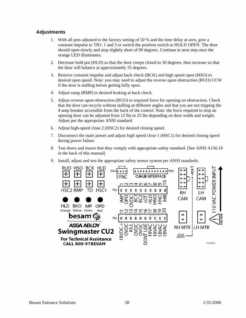
66BAdjustments 1. With all pots adjusted to the factory setting of 50 % and the time delay at zero, give a
constant impulse to TB1: 1 and 3 or switch the position switch to HOLD OPEN. The door should open slowly and stop slightly short of 90 degrees. Continue to next step once the orange LED illuminates.
2. Decrease hold pot (HLD) so that the door creeps closed to 30 degrees, then increase so that the door will balance at approximately 35 degrees.
3. Remove constant impulse and adjust back check (BCK) and high speed open (HSO) to desired open speed. Note: you may need to adjust the reverse upon obstruction (RUO) CCW if the door is stalling before getting fully open.
4. Adjust ramp (RMP) to desired braking at back check.
5. Adjust reverse upon obstruction (RUO) to required force for opening on obstruction. Check that the door can recycle without stalling at different angles and that you are not tripping the 4-amp breaker accessible from the back of the control. Note: the force required to stop an opening door can be adjusted from 12 lbs to 25 lbs depending on door width and weight. Adjust per the appropriate ANSI standard.
6. Adjust high-speed close 2 (HSC2) for desired closing speed.
7. Disconnect the main power and adjust high speed close 1 (HSC1) for desired closing speed during power failure
8. Test doors and insure that they comply with appropriate safety standard. (See ANSI A156.10 in the back of this manual)
9. Install, adjust and test the appropriate safety sensor system per ANSI standards.
Besam Entrance Solutions 39 1/31/2008
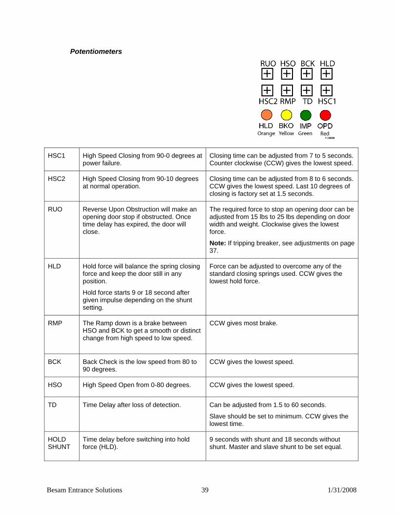
87BPotentiometers
HSC1 High Speed Closing from 90-0 degrees at power failure.
Closing time can be adjusted from 7 to 5 seconds. Counter clockwise (CCW) gives the lowest speed.
HSC2 High Speed Closing from 90-10 degrees at normal operation.
Closing time can be adjusted from 8 to 6 seconds. CCW gives the lowest speed. Last 10 degrees of closing is factory set at 1.5 seconds.
RUO Reverse Upon Obstruction will make an opening door stop if obstructed. Once time delay has expired, the door will close.
The required force to stop an opening door can be adjusted from 15 lbs to 25 lbs depending on door width and weight. Clockwise gives the lowest force.
Note: If tripping breaker, see adjustments on page 37.
HLD Hold force will balance the spring closing force and keep the door still in any position.
Hold force starts 9 or 18 second after given impulse depending on the shunt setting.
Force can be adjusted to overcome any of the standard closing springs used. CCW gives the lowest hold force.
RMP The Ramp down is a brake between HSO and BCK to get a smooth or distinct change from high speed to low speed.
CCW gives most brake.
BCK Back Check is the low speed from 80 to 90 degrees.
CCW gives the lowest speed.
HSO High Speed Open from 0-80 degrees. CCW gives the lowest speed.
TD Time Delay after loss of detection. Can be adjusted from 1.5 to 60 seconds.
Slave should be set to minimum. CCW gives the lowest time.
HOLD SHUNT
Time delay before switching into hold force (HLD).
9 seconds with shunt and 18 seconds without shunt. Master and slave shunt to be set equal.
Besam Entrance Solutions 40 1/31/2008
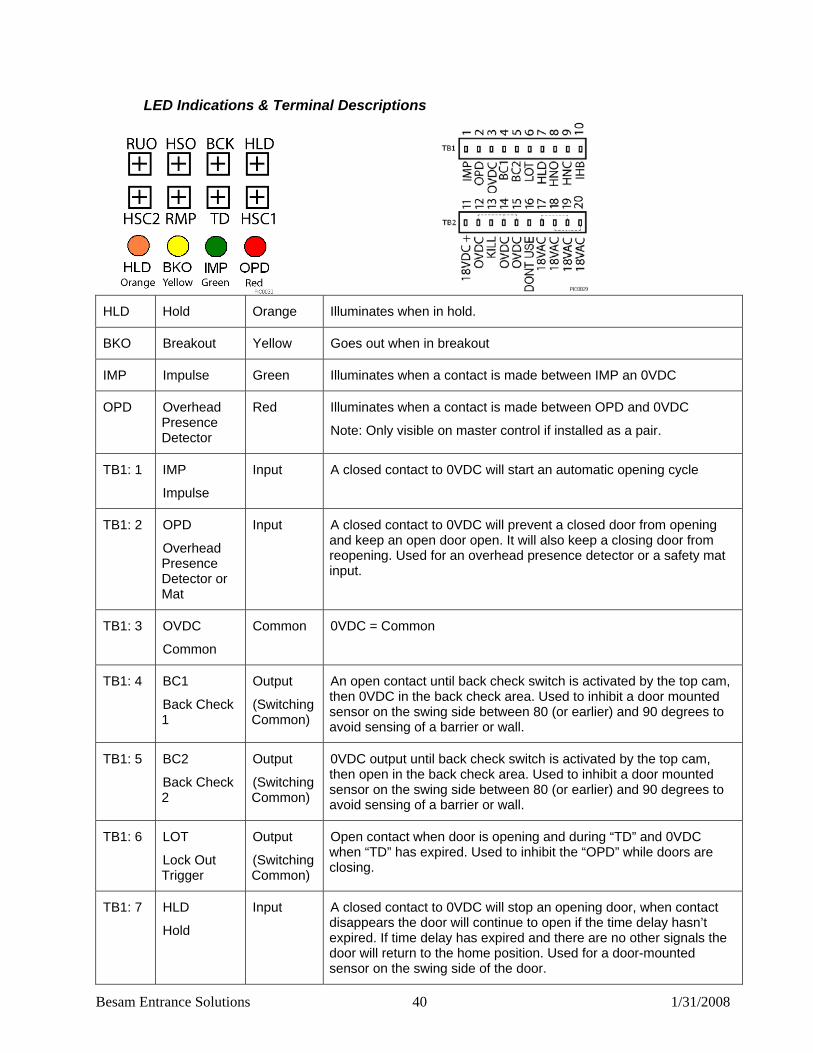
88BLED Indications & Terminal Descriptions
HLD Hold Orange Illuminates when in hold.
BKO Breakout Yellow Goes out when in breakout
IMP Impulse Green Illuminates when a contact is made between IMP an 0VDC
OPD
Overhead Presence Detector
Red Illuminates when a contact is made between OPD and 0VDC
Note: Only visible on master control if installed as a pair.
TB1: 1 IMP
Impulse
Input A closed contact to 0VDC will start an automatic opening cycle
TB1: 2 OPD
Overhead Presence Detector or Mat
Input A closed contact to 0VDC will prevent a closed door from opening and keep an open door open. It will also keep a closing door from reopening. Used for an overhead presence detector or a safety mat input.
TB1: 3 OVDC
Common
Common 0VDC = Common
TB1: 4
BC1
Back Check 1
Output
(Switching Common)
An open contact until back check switch is activated by the top cam, then 0VDC in the back check area. Used to inhibit a door mounted sensor on the swing side between 80 (or earlier) and 90 degrees to avoid sensing of a barrier or wall.
TB1: 5 BC2
Back Check 2
Output
(Switching Common)
0VDC output until back check switch is activated by the top cam, then open in the back check area. Used to inhibit a door mounted sensor on the swing side between 80 (or earlier) and 90 degrees to avoid sensing of a barrier or wall.
TB1: 6 LOT
Lock Out Trigger
Output
(Switching Common)
Open contact when door is opening and during “TD” and 0VDC when “TD” has expired. Used to inhibit the “OPD” while doors are closing.
TB1: 7 HLD
Hold
Input
A closed contact to 0VDC will stop an opening door, when contact disappears the door will continue to open if the time delay hasn’t expired. If time delay has expired and there are no other signals the door will return to the home position. Used for a door-mounted sensor on the swing side of the door.

Besam Entrance Solutions 41 1/31/2008
89BTerminal Descriptions
TB1: 8 HNO
N.O. at home
Output (Switching common)
Utilizes the unused/HOME microswitch on top of SM operator for door closed position. (The output is open when the door is closed, once the door is activated and microswitch is tripped, TB1-8 becomes 0VDC.)
TB1: 9
HNC
N.C. at home
Output (Switching common)
Utilizes the unused/HOME microswitch on top of SM operator for door closed position. (The output is OVDC when the door is closed, once the door is activated and the microswitch is tripped, TB1-9 goes open.)
TB1: 10 IHB
Inhibit
Output Used for sensor systems requiring voltage to switch them ON-OFF, or Inhibit.
Caution, Output to be used along with TB1: 4, 5, 6, 8 and 9 only.
TB2: 11 (+)18 VDC
Output (+) 18VDC to power sensors and accessories
TB2: 12 0VDC Common 0VDC = Common
TB2: 13 Kill Input Closing a contact to 0VDC will cancel all activation and safety signals and cause the door to immediately close.
TB2: 14 0VDC Common 0VDC = Common
TB2: 15 0VDC Common 0VDC = Common
TB2: 16 DONT
USE
N/A (For future use, do not use).
TB2: 17,18
Trans-former
Output 18 VAC 75 VA Class 2 output from transformer
TB2: 19,20
Trans-former
Output 18 VAC 75 VA Class 2 output from transformer
Besam Entrance Solutions 42 1/31/2008
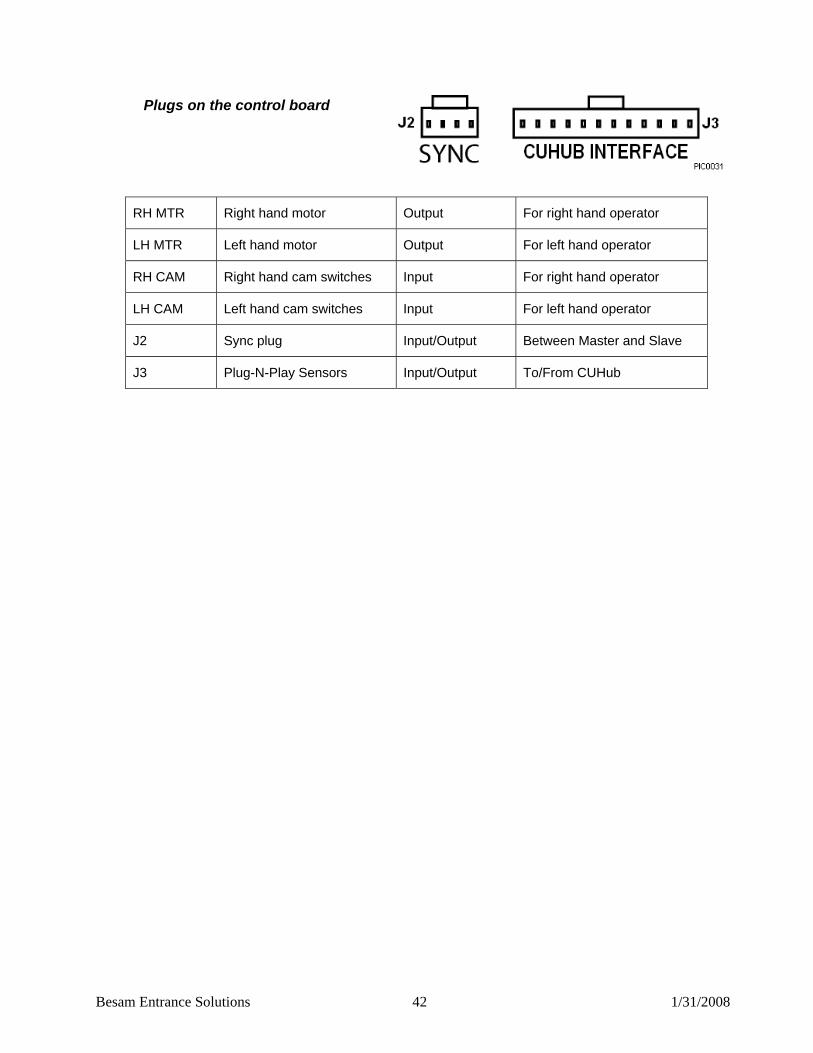
90BPlugs on the control board
RH MTR Right hand motor Output For right hand operator
LH MTR Left hand motor Output For left hand operator
RH CAM Right hand cam switches Input For right hand operator
LH CAM Left hand cam switches Input For left hand operator
J2 Sync plug Input/Output Between Master and Slave
J3 Plug-N-Play Sensors Input/Output To/From CUHub
Besam Entrance Solutions 43 1/31/2008
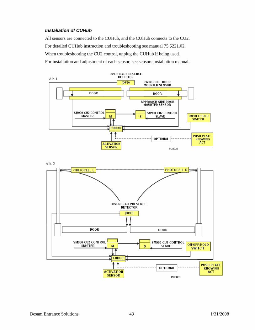
91BInstallation of CUHub All sensors are connected to the CUHub, and the CUHub connects to the CU2.
For detailed CUHub instruction and troubleshooting see manual 75.5221.02.
When troubleshooting the CU2 control, unplug the CUHub if being used.
For installation and adjustment of each sensor, see sensors installation manual.

Besam Entrance Solutions 44 1/31/2008
22BANSI / BHMA A156.10 From American National Standard for Power-Operated Pedestrian Doors. Please refer to the full standard if necessary, obtainable through BHMA at (212) 661-4261. All figures referred to below can be found in the full standard. Excerpts reprinted with BHMA permission.
67BSwinging Doors Automatic Swing Doors have a variety of configurations, including:
A single door swinging in or out, left-handed or right handed
A pair of doors simultaneously swinging in the same direction
A pair of doors simultaneously swinging in opposite directions (double egress)
The door operator is concealed or surface applied. The doors are center pivoted, offset hung, balanced or butt hinged. No matter what the configuration or system, automatic swinging doors shall include guide rails, sensors, or control mats and signage for the safety and convenience of the user.
92B6. Guide Rails 6.1.1 Two guide rails shall be installed on the swing side of each door. Single doors
shall have one on each side of the door and pairs or double egress shall have one rail on each hinge side. Rails shall project to the leading edge of the widest door in the open position.
Exception #1: A wall or separator is permitted to be used in place of a rail, provided that it meets the criteria in 6.2.1 through 6.1.5 Exception #2: Guide rails for swing doors serving both egress and ingress shall project out from the face of the door jambs on the swing side to no less than the outside leading edge of the open door plus 55 in. Exception #3: If double egress doors or a pair of doors is installed in a hallway, no guide rails are required if the distance between the wall and the door in the 90 degree open position does not exceed 10 in. Exception #4: Guide rails for Knowing Act swinging doors serving both egress and ingress shall project out from the face of the doorjambs on the swing side to no less than the outside leading edge of the open door plus 12 in.
6.1.2 A guide rail shall be 30 in. high minimum measured from the floor surface. 6.1.3 A guide rail shall have a panel or divider to inhibit access to the protected
area.
6.1.4 There shall be 6 in. minimum clearance between the rail and the door in the fully open position or between the rail and the leading edge of the door at the point in its arc of travel when it is closest to the rail. There shall be a 2 in. minimum clearance between the rail at the hinge side and the door in the fully open position.
6.1.5 Free standing guide rails shall have a maximum dimension between the rail and the jamb (or other adjacent surfaces) of 6 in.
For control mat adjustments, see full standard
Besam Entrance Solutions 45 1/31/2008
93B8. Sensors
8.1 General Requirements for Sensors 8.1.1 Activating zones for swinging, sliding and folding doors shall
have a minimum width equal to the width of the clear opening measured at 8 in. and 30 in. perpendicular from the face of the closed door(s). The length from the face of the door shall be 43 in. minimum measured at the center of the clear opening. Detection shall be effective to within 5 in. from the face of the door measured at the center of the clear opening.
8.1.2 Motion sensors shall detect a 28 in. minimum high person, moving at a rate of 6 in. per second minimum toward the center of the door within the detection zone described.
8.1.3 Presence sensors shall detect a stationary 28 in. minimum high person within the detection areas described for a minimum of 30 sec.
8.2 Swinging Doors 8.2.1 Swinging doors shall have an activating zone as described in
8.1.1. 8.2.2 A safety zone shall be provided on the swing side of all power
operated swinging doors. 8.2.2.1 If an overhead sensor(s) is used to provide a safety zone, the
length of the active area shall be effective to within 5 in. from the face of the closed door measured at the center of the door opening. The safety zone shall extend 5 in. minimum beyond the leading edge of the door in the open position when measured at the center of the door opening. The width of the active area measured perpendicular from the face of the closed door shall be the door opening less 5 in. maximum measuring both sides for a total of 10 in. maximum parallel to the face of the door at a distance of 8 in. and 30 in.
When the safety zone is occupied by a 28 in. minimum high person fully in the swing path of a fully open or closed door, the door oper-ator shall not operate. 8.2.2.2 When an overhead sensor is prevented from providing a
safety signal to the control during the closing cycle, an additional sensor, sensors or photo beam shall be used to either (1) inhibit reopening of the door until the safety zone is cleared or(2) stop, reverse or slow to a maximum latch edge speed of 4 inches per second measured within 1 inch of the latch edge before any contact is made.

Besam Entrance Solutions 46 1/31/2008
8.2.2.3 If a door mounted sensor is used to provide a safety zone, it shall be effective to within 5 in. from the face of the door for the width of the door less 5 in. from the pivot point and to within 1 in. of the lead edge. A door-mounted sensor on either side of the door shall detect a 28 in. minimum high person fully in the swing path, during the opening and clos-ing cycle and shall cause the door to reverse direction, stop or slow down to a maximum latch edge speed of 4 inches per second measured within 1 inch of the latch edge before any contact is made.
8.2.3 Swinging doors serving both egress and ingress, including non-knowing act double egress doors, shall have on the swing side, a safety zone as described in 8.2.2 and an activating zone. The length of the activating zone shall be established as follows: The activating zone starts adjacent to the safety zone and extends an additional 55 in. from the leading edge of the door in the open position. The activating zone shall have a minimum width equal to the width of the clear opening measured at 8 in. and 30 in. from the interface of the safety and activating zones.
8.2.5 When sensors are used to provide both an activating and a safety zone, if the distance between the two non-overlapping zones exceeds 8 in. the door system shall:1) Be equipped with a safety control mat; or2) Be equipped with a presence sensor across the door opening; or3) Have a door closing cycle delay of 4 seconds minimum after the activating zone is clear; or4) Be equipped with a door-mounted sensor on the non-swing side as described in 8.2.2.3.
For knowing Act and double egress doors, see full standard Section 9.

Besam Entrance Solutions 47 1/31/2008
94B10. Entrapment Protection
10.2 Swinging Doors 10.2.1 The opening time of a swing door to 80 degrees shall not be less
than 1.5 seconds 10.2.2 The force required to prevent a stopped power operated door in
the last 10 degrees of opening from moving in the direction of opening shall not exceed 40 lbs. Measured 1 in. from the lock edge of the door.
10.2.3 Back check shall occur at no less than 10 degrees of the full open position.
10.2.4 Swing doors utilizing sensors or control mats shall remain open a minimum of 1.5 seconds after loss of detection unless other-wise specified in this standard.
10.2.5 A swing door shall be adjusted so that the closing times to latch shall be the minimum values in the following table:
Inches (mm) Lbs. (kg) Time
(D) (W) T (secs.)
36 (914) & under to 100 (45) 2.0
36 (914) to 140 (64) 2.3
42 (1067) to 110 (50) 2.3
42 (1067) to 150 (68) 2.7
48 (2119) to 120 (55) 2.8
48 (2119) to 160 (73) 3.2
48 (2119) to 220 (99) 4.0
10.2.6 Latch Check shall occur for swinging doors at no less than 10 degrees from closed position and the door shall not close through the final 10 degrees in less than 1.5 seconds.
10.2.7 The force required to prevent a stopped power operated swing-ing door from moving in the direction of closing shall not exceed 30 lbs. Measured 1 in. from the lock edge of the door at any point in the closing cycle.
10.2.8 In the event of a power failure, a swing door shall be capable of being opened manually with no greater than 30 lbs. Applied 1 in. from the edge of the lock stile to open.
10.2.9 Swinging doors provided with a break away device shall require no more then 50 lbs. Applied 1 in. from the edge of the lock stile to open. When the door(s) is opened in the breakout mode, power-operating components excluding spring power shall not operate the door.

Besam Entrance Solutions 48 1/31/2008
10.2.10 The opening at hinge side of swinging door shall be: a) Less than ¼ in./6 mm wide with the door in any position, or b) At least ¾ in./19 mm wide with the door in any position. A door that does not comply with the above is acceptable if provided with a finger guard.
95B11. Signage
Consistent with section 2.2.2 of ANSI Z535.4 the “signage and warnings” guidelines of A156.10 are recognized, industry specific standards that predate the adoption of Z535.4 and are not replaced by the standards set forth therein.
11.1 All Swinging, sliding and folding doors shall be equipped with signage visible from both sides reading “AUTOMATIC DOOR” with letters ½ in. high minimum. The sign described in figures B-1, B-3, and B-5 shall be permitted to be used to satisfy this requirement.
11.2.1 An arrow sign shall be visible from the approach side of a swinging door mounted on the door at a height of 58”+ 5 in. from the floor to the center line of the sign. The sign shall be a minimum of 6 in. in diameter, having a green circle surrounding a black arrow on a white background.
11.2.2 An International “DO NOT ENTER” sign shall be visible from the side of doors that swings towards pedestrians attempting to travel in the wrong direction mounted on the door at a height 58”+ 5 in. from the floor to the center line of the sign. The sign shall be a minimum of 6 in. in diameter, having a red circle with the wording, “DO NOT ENTER”, in the red circle
Besam Entrance Solutions 49 1/31/2008
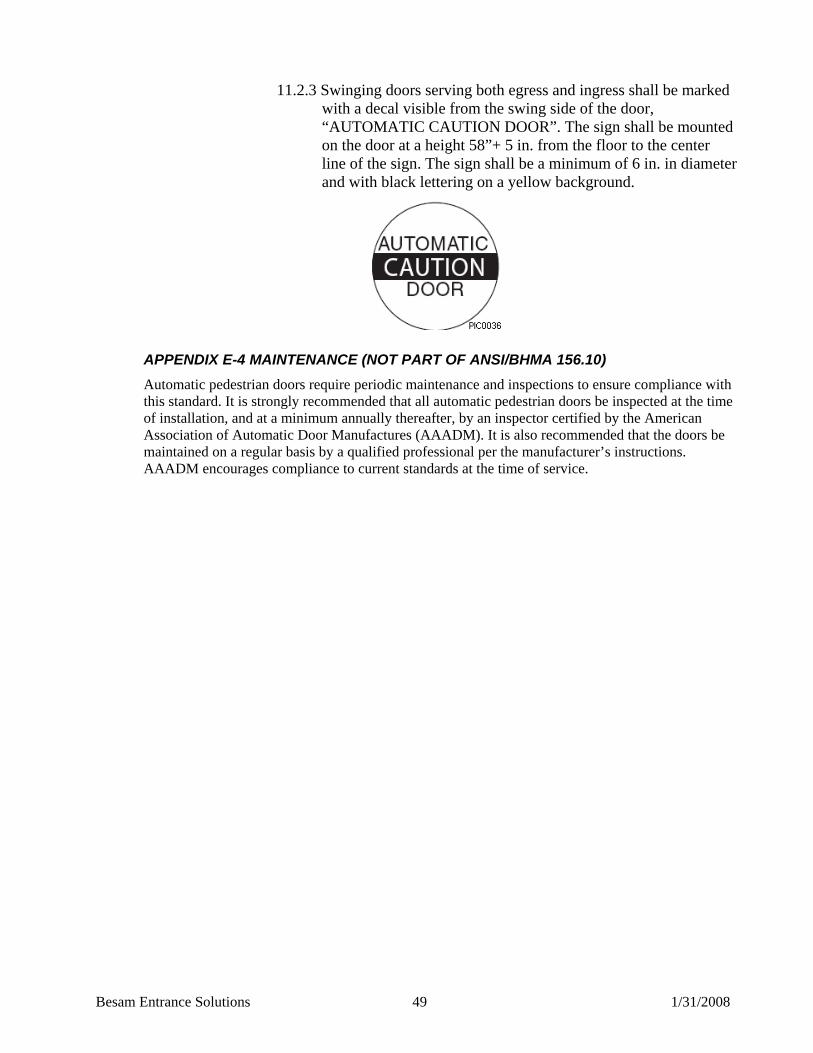
11.2.3 Swinging doors serving both egress and ingress shall be marked with a decal visible from the swing side of the door, “AUTOMATIC CAUTION DOOR”. The sign shall be mounted on the door at a height 58”+ 5 in. from the floor to the center line of the sign. The sign shall be a minimum of 6 in. in diameter and with black lettering on a yellow background.
96BAPPENDIX E-4 MAINTENANCE (NOT PART OF ANSI/BHMA 156.10) Automatic pedestrian doors require periodic maintenance and inspections to ensure compliance with this standard. It is strongly recommended that all automatic pedestrian doors be inspected at the time of installation, and at a minimum annually thereafter, by an inspector certified by the American Association of Automatic Door Manufactures (AAADM). It is also recommended that the doors be maintained on a regular basis by a qualified professional per the manufacturer’s instructions. AAADM encourages compliance to current standards at the time of service.
Besam Entrance Solutions 50 1/31/2008
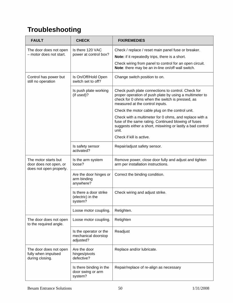
23BTroubleshooting FAULT CHECK FIX/REMEDIES
The door does not open – motor does not start.
Is there 120 VAC power at control box?
Check / replace / reset main panel fuse or breaker.
Note: if it repeatedly trips, there is a short.
Check wiring from panel to control for an open circuit. Note: there may be an in-line on/off wall switch.
Is On/Off/Hold Open switch set to off?
Change switch position to on. Control has power but still no operation
Is push plate working (if used)?
Check push plate connections to control. Check for proper operation of push plate by using a multimeter to check for 0 ohms when the switch is pressed, as measured at the control inputs.
Check the motor cable plug on the control unit.
Check with a multimeter for 0 ohms, and replace with a fuse of the same rating. Continued blowing of fuses suggests either a short, miswiring or lastly a bad control unit.
Check if kill is active.
Is safety sensor activated?
Repair/adjust safety sensor.
Is the arm system loose?
Remove power, close door fully and adjust and tighten arm per installation instructions.
Are the door hinges or arm binding anywhere?
Correct the binding condition.
Is there a door strike (electric) in the system?
Check wiring and adjust strike.
The motor starts but door does not open, or does not open properly.
Loose motor coupling. Retighten.
Loose motor coupling. Retighten The door does not open to the required angle.
Is the operator or the mechanical doorstop adjusted?
Readjust
Are the door hinges/pivots defective?
Replace and/or lubricate. The door does not open fully when impulsed during closing.
Is there binding in the door swing or arm system?
Repair/replace of re-align as necessary

Besam Entrance Solutions 51 1/31/2008
FAULT CHECK FIX/REMEDIES
Are speeds and power levels set correctly?
Retune control.
Is there a shorted input signal?·
Correct the short.
Is the 3-way switch (if used) in hold open position?
Switch to on position.
The door does not close, motor does not shut off.
Is the safety sensor active?
Repair the safety sensor.
If the door still does not close, replace the control unit.
Are the door or hinges binding?
Repair or replace door or hinges. The door does not close fully.
Is the door arm binding or adjusted correctly?
Repair or readjust door arm.
The motor and transformer get hot.
Is the hold force set too high?
Readjust the hold force – see instructions.
Door is only opening to 5 degree and then stopping.
Reverse upon obstruction “RUO” is set too low.
Increase RUO pot.
Door will not stop at presence detect, creeps open.
Hold force “HLD” is too high.
Decrease HLD pot.
Slave is dead and closed and the master stays open and will not close.
Power to slave has disappeared.
Reset breaker at transformer

Besam Entrance Solutions 52 1/31/2008
24BFrequently Asked Questions Q. What will happen if I mount the surface-applied operator at a center line (1) to center line (2) dis-tance different than the one recommended? A. It will alter the manual push open force. Mounting the operator closer to the hinge gives the operator less leverage (power) to open the door, and thus lowers the manual push open force. It also lowers the amount of spring force available to close the door and hold it closed. Mounting the operator further from the hinge has the opposite effect.
Note! Mounting the operator at any distance other than the recommended distance CL1 to CL2 in this manual (reference section titled, “Surface Mount Installation”) can damage the operator or exceed ANSI/ BHMA requirements. Q. Why does my door arm slip? A. Because the slot in the main arm and the slot in the shaft adapter was not lined up as on the illustration, see picture reference section titled, “Arm Systems (Surface Applied).

Besam Entrance Solutions 53 1/31/2008
25BPlanned Maintenance Checklist
Measure / Adjust Speeds – Measure to ANSI/BHMA A156.10 and local codes; adjust if necessary.
Measure / Adjust Forces – Measure to ANSI/BHMA A156.10 and local codes;
adjust if necessary.
Measure / Adjust Time Delays – Measure to ANSI/BHMA A156.10 and adjust if necessary.
Check Functioning – Mats, Sensors, Operator/Control, and Push Plates per
device checklist and AAADM.
Check Signage – Are all signs in place, readable, and in good condition?
Check Door Hinging / Mechanical Soundness – all attachments, covers, arms, crash bars, etc.
Check Finger Guards, Glass and Glass Stops, Trip Hazards, Rails, Sharp
Edges.
Check Emergency Egress (if so equipped).
Check all wiring for good connections, proper insulation and clearance from moving parts.
Go through Daily Safety Checklist with facility manager.

Besam Entrance Solutions 54 1/31/2008
26BSpare Parts Part Number Description View
US05-0583-11 Swingmaster 900 OHC Operator – Light Spring
US05-0583-12 Swingmaster 900 OHC Operator – Medium Spring
US05-0583-21 Swingmaster 900 SA Operator – Light Spring
US05-0583-22 Swingmaster 900 SA Operator – Medium Spring
US02-0583-01 Swingmaster 900 CU2 Control

Besam Entrance Solutions 55 1/31/2008
Part Number Description View
US02-0583-02 Swingmaster CUHub Module
US02-0583-13 P-N-P 3-Postion Switch (ON/OFF/HOLD)
US02-0583-14 Swingmaster CU2 Sync (5ft) Cable (For Pairs)
US02-0583-04 Swingmaster CU2 Switch Harness
US02-0583-05 Swingmaster CU2 to CUHub Cable
US03-0579-01 Swingmaster 900 Back check Cam
US03-0579-02 Swingmaster 900 Home Cam
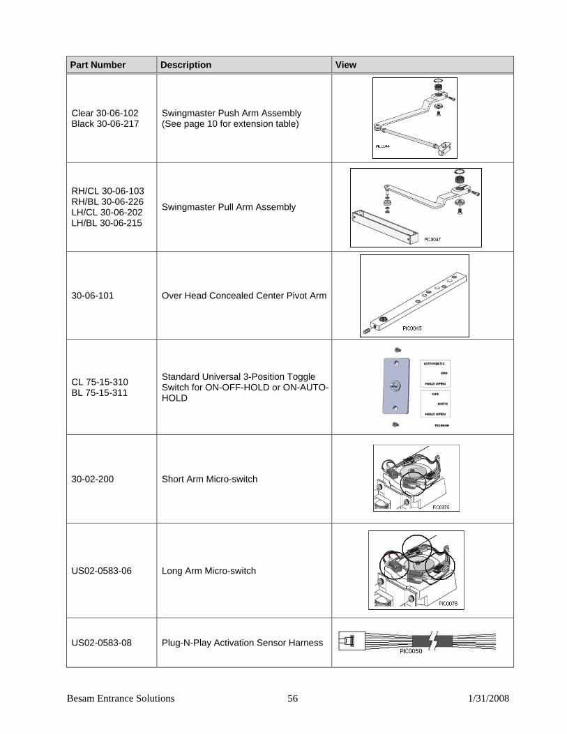
Besam Entrance Solutions 56 1/31/2008
Part Number Description View
Clear 30-06-102 Black 30-06-217
Swingmaster Push Arm Assembly (See page 10 for extension table)
RH/CL 30-06-103 RH/BL 30-06-226 LH/CL 30-06-202 LH/BL 30-06-215
Swingmaster Pull Arm Assembly
30-06-101 Over Head Concealed Center Pivot Arm
CL 75-15-310 BL 75-15-311
Standard Universal 3-Position Toggle Switch for ON-OFF-HOLD or ON-AUTO-HOLD
30-02-200 Short Arm Micro-switch
US02-0583-06 Long Arm Micro-switch
US02-0583-08 Plug-N-Play Activation Sensor Harness
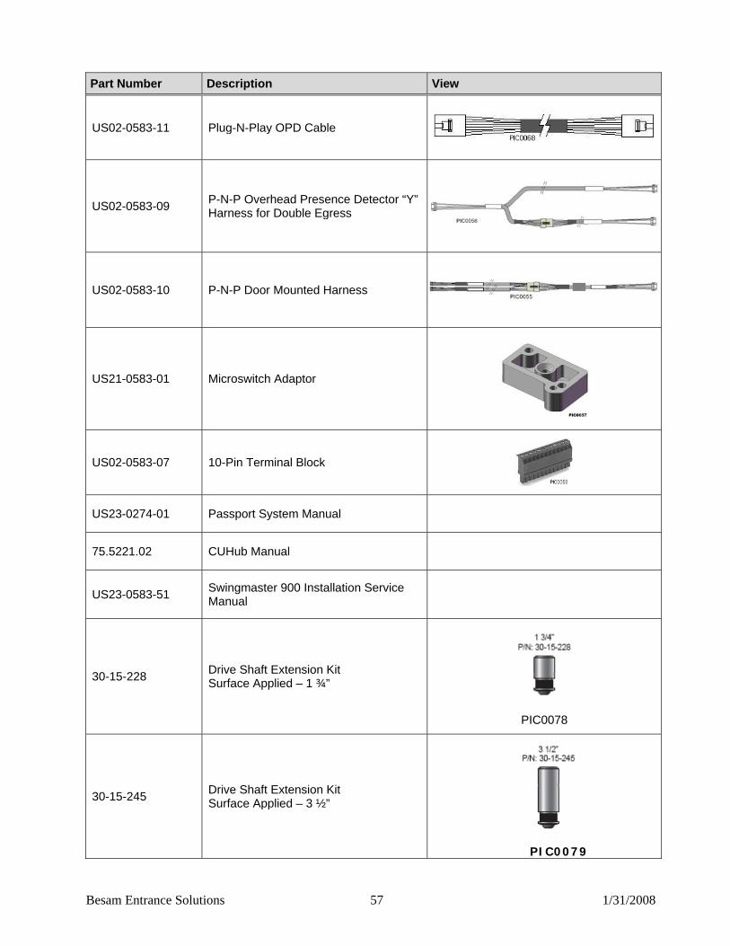
Besam Entrance Solutions 57 1/31/2008
Part Number Description View
US02-0583-11 Plug-N-Play OPD Cable
US02-0583-09 P-N-P Overhead Presence Detector “Y” Harness for Double Egress
US02-0583-10 P-N-P Door Mounted Harness
US21-0583-01 Microswitch Adaptor
US02-0583-07 10-Pin Terminal Block
US23-0274-01 Passport System Manual
75.5221.02 CUHub Manual
US23-0583-51 Swingmaster 900 Installation Service Manual
30-15-228 Drive Shaft Extension Kit Surface Applied – 1 ¾”
PIC0078
30-15-245 Drive Shaft Extension Kit Surface Applied – 3 ½”
PIC0079

Besam Entrance Solutions 58 1/31/2008
Part Number Description View
30-15-246 Drive Shaft Extension Kit Surface Applied – 5”
PIC0080
US21-0583-02 SBK30 Adapter for Mounting to Jambs
PIC0082
US21-0583-03 SBK30 Adapter for Mounting to Guide Rails
PIC0083
US03-0579-03 Controller Strap
PIC0091
US02-0503-16 Fuse, 2A, 250V PIC0094

Besam Entrance Solutions 59 1/31/2008
27BWiring Diagrams 68BCU2 Backward Compatibility with LO21B
All new micro-switches must be installed per illustration below.

Besam Entrance Solutions 60 1/31/2008

NOTE


Besam Entrance Solutions 1900 Airport Road Monroe, NC 28110
Tel: (704) 290-5520, Fax: (704) 290-5544
©Copyright 2008 Besam Entrance Solutions. May not be reprinted or reproduced without permission.


![[XLS] · Web view450. 90. 450. 900. 900. 225. 450. 450. 900. 450. 225. 270. 4.5. 450. 450. 450. 450. 450. 450. 450. 450. 450. 900. 450. 450. 450. 112.5. 900. 900. 450. 112.5. 450.](https://static.fdocuments.in/doc/165x107/5b3c17127f8b9a213f8d0b42/xls-web-view450-90-450-900-900-225-450-450-900-450-225-270-45.jpg)