Bently Nevada* Asset Condition Monitoringgeoilandgas.ge.com.cn/digitalsolutions/sites/default...Part...
54
Part Number 141078-01 Rev. V (08/15) Bently Nevada* Asset Condition Monitoring Installation Manual 3300 XL 8mm & 3300 5mm Proximity Transducer System
Transcript of Bently Nevada* Asset Condition Monitoringgeoilandgas.ge.com.cn/digitalsolutions/sites/default...Part...
Part Number 141078-01 Rev. V (08/15)
Bently Nevada* Asset Condition Monitoring
Installation Manual
3300 XL 8mm & 3300 5mm Proximity Transducer System

3300 XL 8mm & 3300 5mm Proximity Transducer System
ii
© 1999 - 2015 Bently Nevada, Inc. All rights reserved.
The information contained in this document is subject to change without notice. * Denotes a trademark of Bently Nevada, Inc., a wholly owned subsidiary of General Electric Company. Bently Nevada, Proximitor, Keyphasor, TipLoc, CableLoc, FluidLoc, ClickLoc The following are trademarks of the legal entities cited: Teflon is a trademark of E. I. du Pont de Nemours and Company. Printed in USA. Uncontrolled when transmitted electronically
Contact Information The following contact information is provided for those times when you cannot contact your local representative:
Mailing Address 1631 Bently Parkway South Minden, Nevada USA 89423 USA
Telephone 1.775.782.3611 1.800.227.5514
Fax 1.775.215.2873 Internet www.gemeasurement.com

iii
Additional Information
Notice: This manual does not contain all the information required to operate and maintain the product. Refer to the following manuals or application notes for other required information.
Proximity Transducer Systems are electronic devices typically used in industrial applications. The 3300 XL Transducer System has been certified using the same Technical Construction File (TCF) and Declaration of Conformity as the 3300 8mm Transducer System because they are similar in design and application. The 3300 XL Proximity Transducer System consists of a Proximitor* Sensor, Proximity Probe, and Extension Cable.
Installing the Transducer Guidelines for Grounding (Earthing) Bently Nevada Rotating Machinery Information Systems. Installation of Electrical Equipment in Hazardous Areas. Considerations when using Eddy Current Proximity Probes for Overspeed Protection Applications. “Glitch”: Definition of and Methods for Correction, Including Shaft Burnishing to Remove Electrical Runout.
Transducer Installation Accessories 31000/32000 Proximity Probe Housing Manual (Part Number 124200-01). 31000/32000 Proximity Probe Housing Data Sheet (Part Number 141610-01) Housings for Proximitor Sensors and Interface Modules Data Sheet (Part Number 141599-01) 3300 XL Monitor and Transducer Verification Kits Data Sheet (Part Number 141196-01)
Electrical and Mechanical Runout API 670, Fourth Edition, Sections 6.1.1 (Location and Orientation – Radial Shaft Vibration Probes) and 6.1.2 (Location and Orientation – Axial Position Probes. Available from the American Petroleum Institute, Publications and Distribution, 1220 L Street NW, Washington DC, 20005, USA.
Reference (133055-01) Bently Nevada Glossary.

3300 XL 8mm & 3300 5mm Proximity Transducer System
iv
Symbols Procedures in this manual use the following symbols:
Connect Disconnect Observe Record
Value
Product Disposal Statement
Customers and third parties, who are not member states of the European Union, who are in control of the product at the end of its life or at the end of its use, are solely responsible for the proper disposal of the product. No person, firm, corporation, association or agency that is in control of product shall dispose of it in a manner that is in violation of any applicable federal, state, local or international law. Bently Nevada Inc. is not responsible for the disposal of the product at the end of its life or at the end of its use.

v
Contents 1. System Description........................................................................................ 1
1.1 Transducer Systems ......................................................................................................................... 1 1.2 Proximitor Sensor .............................................................................................................................. 2 1.3 Proximity Probe and Extension Cable ...................................................................................... 2 1.4 Connectors ........................................................................................................................................... 2 1.5 Extended Temperature Range (ETR) Applications .............................................................. 3 1.6 Receiving, Inspecting, and Handling the System ................................................................ 4 1.7 Customer Service .............................................................................................................................. 4
2. Installation ...................................................................................................... 5
2.1 Installing the Probe ........................................................................................................................... 5 2.2 Mounting the Proximitor Sensor ................................................................................................. 8 2.3 Interchangeable Mounting Feet ................................................................................................. 9 2.4 Mounting the Proximitor Sensor with DIN Mount Part ................................................... 10 2.5 Removing the Proximitor Sensor from the DIN Rail ......................................................... 11 2.6 Termination of Field Wiring in the Terminal Block ............................................................ 12 2.7 Routing the Extension Cable and Field Wiring ................................................................... 13
3. Maintenance and Troubleshooting .......................................................... 15
3.1 Scale Factor Verification .............................................................................................................. 17 3.2 Troubleshooting ............................................................................................................................... 22 3.3 Fault Type 1: VXDCR > -17.5 Vdc or VXDCR < -26 Vdc ........................................................... 24 3.4 Fault Type 2: VSIG = O Vdc ........................................................................................................... 25 3.5 Fault Type 3: -1 Vdc < VSIG < 0 Vdc .......................................................................................... 26 3.6 Fault Type 4: VXDCR <VSIG < VXDCR + 2.5 Vdc ........................................................................... 29 3.7 Fault Type 5: VSIG = VXDCR ............................................................................................................. 30
4. System Specifications ................................................................................. 31
4.1 Electrical .............................................................................................................................................. 31 4.2 Environmental Limits ..................................................................................................................... 36
4.2.1 Probe Temperature Range ..................................................................................................... 36 4.2.2 Extension Cable Temperature Range ............................................................................... 37 4.2.3 Proximitor Sensor Temperature Range ............................................................................ 38
5. System Dimensional Drawings ................................................................. 39
5.1 3300 XL 8mm Proximity Probes, Standard Mount ........................................................... 39 5.2 3300 5mm Proximity Probes ...................................................................................................... 40 5.3 3300 XL 8mm Proximity Probes, Reverse Mount .............................................................. 41 5.4 3300 XL 8mm Proximity Probes, Smooth Case .................................................................. 42

3300 XL 8mm & 3300 5mm Proximity Transducer System
vi
5.5 Extension Cable ................................................................................................................................ 43 5.6 Extension Cable with Connector Protectors ....................................................................... 43 5.7 Proximitor Sensor ............................................................................................................................ 44
6. Index ................................................................................................................47

Section 1 - System Description
1
1. System Description 1.1 Transducer Systems
The 3300 XL 8mm Proximity Transducer System consists of:
• a 3300 XL 8mm probe
• a 3300 XL extension cable1
• a 3300 XL Proximitor Sensor2
The system provides an output voltage that is directly proportional to the distance between the probe tip and the observed conductive surface and can measure both static (position) and dynamic (vibration) values. The system’s primary applications are vibration and position measurements on fluid-film bearing machines, as well as Keyphasor* reference and speed measurements3.
The 3300 XL 8mm system delivers the most advanced performance in our eddy current proximity transducer systems. The standard 3300 XL 8mm 5-metre system also fully complies with the American Petroleum Institute’s (API) 670 Standard (4th Edition) for mechanical configuration, linear range, accuracy, and temperature stability. All 3300 XL 8mm proximity transducer systems provide this level of performance and support complete interchangeability of probes, extension cables, and Proximitor sensors, eliminating the need to match or bench calibrate individual components
Each component of the 3300 XL 8mm Transducer System is backward compatible and interchangeable4 with other non-XL 3300 series 5mm and 8mm transducer system components5. This includes the 3300 5mm probe, which is used when an 8mm probe is too large for the available mounting space4, 5, and 6.
The 3300 5mm Proximity Transducer System consists of:
• a 3300 5mm probe 5, 6, 7
• a 3300 XL extension cable1
• a 3300 XL Proximitor Sensor2
Like the 3300 XL 8mm, the 3300 5mm system also provides an accurate, stable signal output over a wide temperature range while allowing complete interchangeability of probe, extension cable, and Proximitor Sensor without the need for individual component matching or bench calibration.

3300 XL 8mm & 3300 5mm Proximity Transducer System
2
1.2 Proximitor Sensor The 3300 XL Proximitor Sensor incorporates numerous improvements over previous designs. Its physical packaging allows you to use it in high-density DIN-rail installations. You can also mount the sensor in a traditional panel mount configuration, where it shares an identical 4-hole mounting “footprint” with older Proximitor sensor designs. The mounting base for either option provides electrical isolation and eliminates the need for separate isolator plates. The 3300 XL Proximitor Sensor is highly immune to radio frequency interference, allowing you to install it in fiberglass housings without adverse effects from nearby radio frequency signals. The 3300 XL Proximitor Sensor’s improved RFI/EMI immunity satisfies European CE mark approvals without requiring special shielded conduit or metallic housings, resulting in lower installation costs and complexity.
The 3300 XL’s SpringLoc terminal strips require no special installation tools and facilitate faster, more robust field wiring connections by eliminating screw-type clamping mechanisms that can loosen.
1.3 Proximity Probe and Extension Cable The 3300 XL probe and extension cable also reflect improvements over previous designs. A patented TipLoc* molding method provides a more robust bond between the probe tip and the probe body. The probe’s cable incorporates a patented CableLoc* design that provides 330 N (75 lbf) pull strength to more securely attach the probe cable and probe tip.
You can also order 3300 XL 8mm probes and extension cables with an optional FluidLoc* cable option. This option prevents oil and other liquids from leaking out of the machine through the cable’s interior.
1.4 Connectors The 3300 XL 8mm and 3300 5mm probe, extension cable, and Proximitor Sensor have corrosion-resistant, gold-plated ClickLoc* connectors. These connectors require only finger-tight torque (connectors will "click"), and the specially engineered locking mechanism prevents the connectors from loosening. These connectors require no special tools for installation or removal.
You can order the 3300 XL 8mm probes and extension cables with optional connector protectors installed. We can also supply connector protectors separately for field installations (such as when an application must run the cable through restrictive conduit). We recommend connector protectors for all installations to provide increased environmental protection8.

Section 1 - System Description
3
1.5 Extended Temperature Range (ETR) Applications An Extended Temperature Range (ETR) Probe and Extension Cable are available for applications where either the probe lead or extension cable may exceed the 177°C (350°F) temperature specification. The Extended Temperature Range Probe has an extended temperature rating for up to 260°C (500°F) for the probe lead and connector. The probe tip must remain below 218°C (425°F). The Extended Temperature Range Extension Cable is also rated for up to 260°C (500°F). Both the ETR probe and cable are compatible with standard temperature probes and cables. For example, you can utilize an ETR probe with the 330130 extension cable. The ETR system uses the standard 3300 XL Proximitor Sensor. When using any ETR component as part of your system, the accuracy is limited to the accuracy of the ETR system.
Notes:
1. 1-metre systems do not use an extension cable.
2. Proximitor Sensors are supplied by default from the factory calibrated to AISI 4140 steel. Calibration to other target materials is available upon request.
3. Consult Bently Nevada Applications Note Considerations when using Eddy Current Proximity Probes for Overspeed Protection Applications when considering this transducer system for tachometer or overspeed measurements.
4. 3300 XL 8mm components are both electrically and physically interchangeable with non-XL 3300 5mm and 8mm components. Although the packaging of the 3300 XL Proximitor Sensor differs from its predecessor, it is designed to fit in the same 4-hole mounting pattern when used with the 4-hole mounting base, and will fit within the same mounting space specifications (when minimum permissible cable bend radius is observed).
5. When XL and non-XL 3300-series 5mm and 8mm system components are mixed, system performance is limited to the specifications for the non-XL 3300 5mm and 8mm Transducer System.
6. A 5mm probe uses smaller physical packaging while providing the same linear range as a 3300 XL 8mm probe (ref 141194-01); however, it does not permit reduced side view clearances or tip-to-tip spacing requirements compared to an XL 8mm probe. It is used when physical (not electrical) constraints preclude the use of an 8mm probe, such as mounting between thrust bearing pads or other constrained spaces. When narrow side view probes are required, use the 3300 XL NSv* probe and extension cable with the 3300 XL NSv Proximitor Sensor (refer to Specifications and Ordering Information p/n 147385-01).
7. XL 8mm probes provide a thicker encapsulation of the probe coil in the molded PPS plastic probe tip. This results in a more rugged probe than the 3300 5mm probe. The larger diameter of the probe body also provides a stronger, more robust case. Bently Nevada Inc. recommends the use of XL 8mm probes when possible to provide optimal robustness against physical abuse.
8. Silicone tape is also provided with each 3300 XL extension cable and can be used instead of connector protectors. Silicone tape is not recommended in applications where the probe-to-extension cable connection will be exposed to turbine oil.

3300 XL 8mm & 3300 5mm Proximity Transducer System
4
1.6 Receiving, Inspecting, and Handling the System The probe, extension cable and Proximitor Sensor are shipped as separate units and must be interconnected at the installation site by the user. Carefully remove all equipment from the shipping containers and inspect the equipment for shipping damage. If shipping damage is apparent, file a claim with the carrier and contact your nearest Bently Nevada sales office. Include part numbers and serial numbers on all correspondence. If no damage is apparent and the equipment is not going to be used immediately, return the equipment to the shipping containers and reseal until ready for use.
Store the equipment in an environment free from potentially damaging conditions such as high temperature or a corrosive atmosphere. See section 4.2 for environmental specifications.
1.7 Customer Service We maintain numerous Sales and Service offices worldwide. To locate the office nearest you, visit our website www.gemeasurement.com and click on the “Contact Us” link. Here, you can also find specifications on all standard product offerings.
Support for products and services should be directed to one of these departments:
For product quotations, product applications, product ordering, scheduling on-site services, and questions regarding existing orders, please contact your Bently Nevada sales office.
For general product pricing, delivery, or other ordering information, contact your local sales office or contact Customer Service Department, Minden, Nevada, USA Phone: 1-775-215-1011 Fax: 1-775-215-2873.
For technical questions or problems regarding our products, contact our Technical Support Staff at:
or at the following locations:
Technical Support (North America) Phone: 1-775-215-1818 Fax: 1-775-215-2890 Toll free (US) 1-800-488-1915

Section 2 - Installation
5
2. Installation This section contains a checklist of items that you must consider when you install a 3300 XL Transducer system.
2.1 Installing the Probe The following figures show the probe sizes and the minimum values for probe separation, side clearance and target configuration. Refer to Table 4-3 for proper torque and the dimensions of the thread.
Callout Description XL 8mm probe 5mm probe
Probe tip 8mm 5mm
Thread types M10x1, 3/8-24, or
unthreaded M8x1 or 1/4-28
Wrench Flats 8mm or 5/16 in. 7mm or 7/32 in.
Lock nut 17mm or 9/16 in.
Hex 13mm or 7/16 in. Hex
Figure 2-1: Probe Dimensions

3300 XL 8mm & 3300 5mm Proximity Transducer System
6
1
2 1. 76.2mm (3.00 in.) minimum (See Note 1 below) 2. 15.2mm (0.60 in.) minimum
Figure 2-2: 5mm and XL 8mm Probe Target Sizes
3
1
2
3
1. 6.4mm (0.25 in.) minimum 2. 17.8mm (0.70 in.) minimum 3. 8.9mm (0.35 in.) minimum
Figure 2-3: 5mm and XL 8mm Probe Mounting Dimensions

Section 2 - Installation
7
3
1
2
2
1. 50.8mm (2.00 in.) minimum (See Note 2 below) 2. 16.0mm (0.63 in.) minimum 3. 40.6mm (1.60 in.) minimum
Figure 2-4: 5mm and XL 8mm Probe-to-Probe Separation Due To Cross Talk
NOTES
1. At or below 76.2mm (3.0 in.), scale factor will increase as the target size is reduced. See the application advisory below.
2. Between 50.8mm (2.0 in.) and 76.2mm (3.0 in.), cross talk will produce a noise signal of up to 50 mV.
Application Advisory
Mounting dimensions and target size affect the scale factor of proximity transducer systems. The minimum
recommended dimensions above were chosen to minimize error yet retain flexibility for different
mounting situations.

3300 XL 8mm & 3300 5mm Proximity Transducer System
8
Adjust the distance between the probe tip and the shaft using one of the methods shown in Figure 2-5. The electrical method for setting the probe gap is preferred.
-24 V ±1-9 V
1.27 mm(50 mil)
1 2
3
48
56
7
9 10 1. Voltmeter 2. Power supply 3. Voltage at center of the linear range (typically –9 V) 4. Space 5. OUT 6. COM 7. VT 8. 10kΩ, 1% resistor 9. Mechanical method 10. Electrical method
Figure 2-5: Methods for Setting the Probe Gap
2.2 Mounting the Proximitor Sensor Mount the Proximitor Sensor in a location that is compatible with its environmental specifications (see section 4.2). Consider the local electrical codes and the presence of hazardous or explosive gas at the installation site. (Refer to the document Installation of Electrical Equipment in Hazardous Areas.)

Section 2 - Installation
9
1
28.7(1.13)
35.1(1.38) (2.79)
70.8
89.4(3.52)
2
1. 35mm Din Rail (Din Rail not included) 2. 89.4mm (3.52 in.) [Additional 3.05mm (0.120 in.) required to remove from DIN rail] 3. Total Length & Mounting options, -11, -51 or –91
Figure 2-6: DIN Rail Mount Dimensions
1
50.8(2.00)
61.0(2.40)
50.8(2.00)
81.3(3.20)
(2.50)63.5
1. Counter-bore 7.37mm (0.290 in.) X 2.67mm (0.105 in.) deep with a 4.0mm (0.158
in.) through hole for an M3.5 or #6 screw (screws not included) 2. Total Length & Mounting options, -10, -50 or -90
Figure 2-7: Panel Mount Dimensions
2.3 Interchangeable Mounting Feet The mounting feet for the 3300 XL Proximitor Sensor are interchangeable. If you purchase a Proximitor Sensor with one mounting option (either the DIN mount option or the panel mount option) you can change the mounting hardware simply by replacing the mounting foot that is currently on the Proximitor Sensor with the other type of mounting foot.

3300 XL 8mm & 3300 5mm Proximity Transducer System
10
1. DIN Mount Part (part number 138493-01) 2. 3300 XL Proximitor Sensor 3. Panel Mount Part (part number 138492-01)
Figure 2-8: Mounting Foot Options
2.4 Mounting the Proximitor Sensor with DIN Mount Part To mount the 3300 XL Proximitor Sensor with a DIN Mount Part on a DIN rail:
1. Install the Proximitor Sensor into the DIN Mount Part (if not already installed) as shown in Figure 2-9.
Figure 2-9: Installing the DIN Rail Mounting Foot
2. Examine the under side of the DIN Mounting Foot. This part has a spring-loaded clip on one side and two protrusions that will catch the edge of the DIN rail on the other side. You must install the side with the two protrusions so that the edge of the DIN rail fits into the gap as shown in Figure 2-10.

Section 2 - Installation
11
1. Spring-loaded clip 2. DIN rail 3. Edge of DIN rail must fit into this gap
Figure 2-10: Inserting the Mounting Foot Onto the DIN Rail
3. Push down on the Proximitor Sensor as shown in Figure 2-11 until the unit “snaps” into place. The unit is now installed.
Figure 2-11: Snapping the Sensor Onto the DIN Rail
2.5 Removing the Proximitor Sensor from the DIN Rail To remove the Proximitor Sensor from the DIN rail, use a regular screwdriver to unclip the unit from the rail.
Insert the screwdriver into the rear of the spring-loaded clip (see Figure 2-12). Push the top of the screwdriver towards the Proximitor Sensor to pry the spring-loaded clip back so that you can remove the Proximitor Sensor from the DIN rail.

3300 XL 8mm & 3300 5mm Proximity Transducer System
12
Figure 2-12: Retracting the Spring-Loaded Clip
2.6 Termination of Field Wiring in the Terminal Block 1. Strip the insulation from the field wiring you will install into the terminal block.
The recommended strip length is 10mm (0.4 in.).
2. You must twist the conductor strands together before installing the field wire into the terminal block (see Figure 2-13). We recommend that you tin the conductor strands as well.
Figure 2-13: Proper Preparation of Wire Strands
3. The terminal block can accommodate field wiring conductor sizes of 0.2 – 1.5 mm2 (16 – 24 AWG).
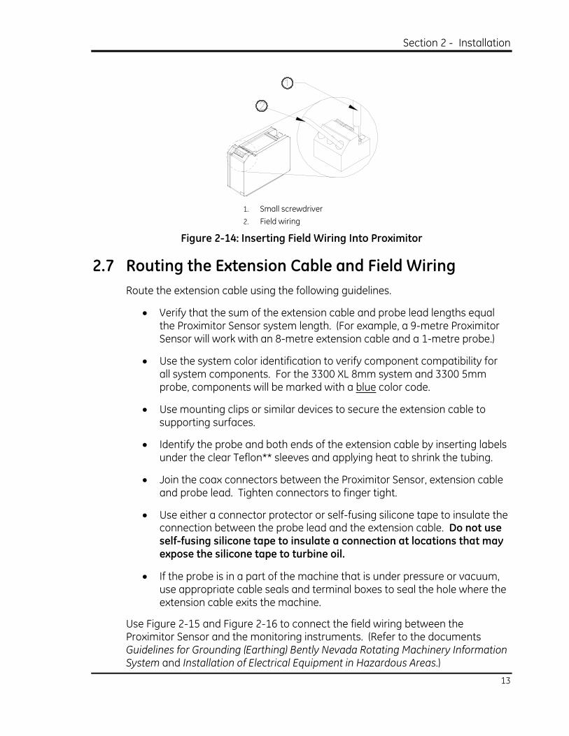
4. Use a small regular screwdriver to push down the orange lever that corresponds to the position in the terminal block where you will install the field wire and insert the field wire (see Figure 2-14).
NOTE
To remove the field wire push down on the orange lever and pull on the field wire to remove it from the terminal block. If the field wiring uses a stranded wire and a strand breaks off inside the terminal block, turn the Proximitor Sensor upside down while pushing down on the orange lever and remove the strand from the terminal block.
Section 2 - Installation
13
1. Small screwdriver 2. Field wiring
Figure 2-14: Inserting Field Wiring Into Proximitor
2.7 Routing the Extension Cable and Field Wiring Route the extension cable using the following guidelines.
• Verify that the sum of the extension cable and probe lead lengths equal the Proximitor Sensor system length. (For example, a 9-metre Proximitor Sensor will work with an 8-metre extension cable and a 1-metre probe.)
• Use the system color identification to verify component compatibility for all system components. For the 3300 XL 8mm system and 3300 5mm probe, components will be marked with a blue color code.
• Use mounting clips or similar devices to secure the extension cable to supporting surfaces.
• Identify the probe and both ends of the extension cable by inserting labels under the clear Teflon** sleeves and applying heat to shrink the tubing.
• Join the coax connectors between the Proximitor Sensor, extension cable and probe lead. Tighten connectors to finger tight.
• Use either a connector protector or self-fusing silicone tape to insulate the connection between the probe lead and the extension cable. Do not use self-fusing silicone tape to insulate a connection at locations that may expose the silicone tape to turbine oil.
• If the probe is in a part of the machine that is under pressure or vacuum, use appropriate cable seals and terminal boxes to seal the hole where the extension cable exits the machine.
Use Figure 2-15 and Figure 2-16 to connect the field wiring between the Proximitor Sensor and the monitoring instruments. (Refer to the documents Guidelines for Grounding (Earthing) Bently Nevada Rotating Machinery Information System and Installation of Electrical Equipment in Hazardous Areas.)

3300 XL 8mm & 3300 5mm Proximity Transducer System
14
OUTCOM
Vt
1
2
34 5
6 7 8
1. Transducer power 2. System common 3. Signal 4. Monitor terminal strip 5. Cable shield 6. Proximitor sensor 7. Connector protector 8. Probe
Figure 2-15: Installation With No Barriers or With 3300/3500 Internal Barriers
VtCOMOUT
1
2
3 5 6 5 7 8 94
1. Transducer power 2. System common 3. Signal 4. Monitor terminal strip 5. Cable shield 6. External barrier 7. Proximitor sensor 8. Connector protector 9. Probe
Figure 2-16: Installation With External Barriers
NOTE
The Proximitor Sensor requires a negative voltage power supply and should be current limited to 1A. The 3500 System provides the correct power supply for the Proximitor Sensor, but if using an alternate power supply, refer to the Power Specification on page 32 for the correct power limitations. Applying a power supply outside of the approved range can result in incorrect performance or damage to the equipment.

Section 3 - Maintenance and Troubleshooting
15
3. Maintenance and Troubleshooting This section shows how to verify that the system is operating properly and identify parts of the system that are not working properly.
When properly installed and verified, the 3300 XL Transducer System (probe, cable and Proximitor Sensor) does not need calibration or verification at regular intervals. If the monitor OK light (green) indicates a NOT OK condition (i.e., the light is not illuminated), then
• a fault has occurred in the field wiring/transducer system/power source,
• the probe is too close to target,
• the probe is detecting material other than the target,
• the target material is not AISI 4140, or
• the probe is too far from the target.
We recommend the following practices to ensure continued satisfactory operation of your 3300 XL system. Verify operation using the scale factor verification method on the following page, if you
• replace any of the system components (probe, cable or Proximitor Sensor),
• remove and reinstall or move and remount any of the components,
• determine that any of the components are damaged, or
• overhaul the machine being monitored.
Please note that a sudden change in the output of the transducer system or other output that is not consistent with the associated machinery’s trended data is, in most instances, not a transducer problem but a machinery problem. You can verify the transducer system under these conditions at your discretion.
Under harsh operating conditions, some users prefer to verify all transducers at a regular interval. As noted above, the 3300 XL Transducer System does not require this. Users who wish to verify the system on a regular interval should use an interval consistent with their own practices and procedures, which may or may not be based upon ISO 10012-1 “Quality Assurance Requirements for Measuring Equipment”.
For target materials other than AISI 4140 steel and for other special applications, contact your local sales office.
3300 XL 8mm & 3300 5mm Proximity Transducer System
16
NOTE
Hazardous location areas must be free of hazardous materials before any
maintenance or troubleshooting can be performed.
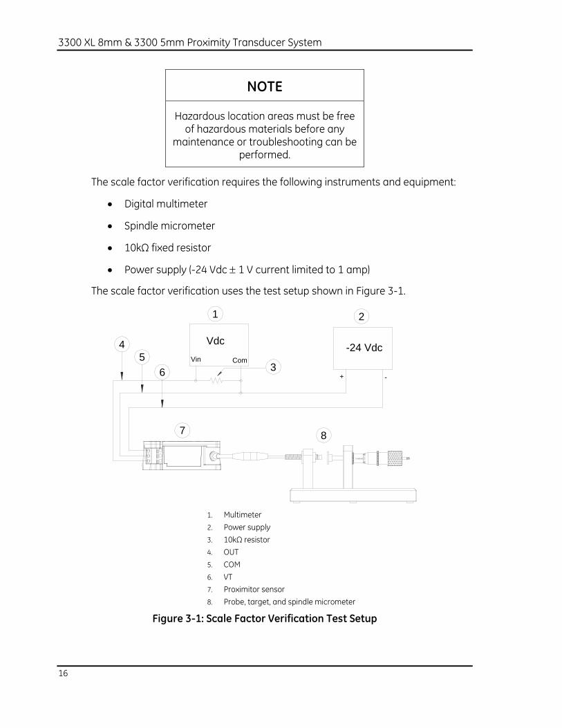
The scale factor verification requires the following instruments and equipment:
• Digital multimeter
• Spindle micrometer
• 10kΩ fixed resistor
• Power supply (-24 Vdc ± 1 V current limited to 1 amp)
The scale factor verification uses the test setup shown in Figure 3-1.
-24 VdcVdcVin Com
+ -
21
3
45
6
7 8
1. Multimeter 2. Power supply 3. 10kΩ resistor 4. OUT 5. COM 6. VT 7. Proximitor sensor 8. Probe, target, and spindle micrometer
Figure 3-1: Scale Factor Verification Test Setup

Section 3 - Maintenance and Troubleshooting
17
3.1 Scale Factor Verification 1. Compensate for mechanical backlash and adjust the spindle
micrometer for electrical zero position by;
a. setting the micrometer to 0.46mm (18 mils) or less,
b. then backing the spindle out to 0.50mm (20 mils).
Note: If after performing this procedure, the spindle is accidently turned in toward 0mm (mils), the procedure must be repeated.
1
2
1. Set micrometer to 0.46mm (18 mils) or less 2. Back spindle out to 0.50mm (20 mils)
Figure 3-2: Adjusting Spindle Micrometer for Electrical Zero

3300 XL 8mm & 3300 5mm Proximity Transducer System
18
2. With the micrometer set at 0.50mm (20 mils), adjust the probe gap to electrical zero by moving the probe until the multimeter reads –3.0 ± 0.1 Vdc. Be careful not to move the spindle of the micrometer while adjusting the probe position.
1
2
1. Multimeter 2. Electrical zero reading of –3.0 Vdc ± 0.1 Vdc
Figure 3-3: Adjusting Gap for Electrical Zero

Section 3 - Maintenance and Troubleshooting
19
3. Compensate for mechanical backlash in the micrometer and adjust to the start of the linear range;
a. with the micrometer at electrical zero as described in step 1, turn the spindle in to approximately 0.20mm (8 mils) or less,
b. then carefully back the spindle out to 0.25mm (10 mils).
Note: If during step b, the spindle is accidently turned past the 0.25mm (10 mil) mark, do not just turn the spindle back to the 0.20mm (10 mil) mark. To prevent backlash errors, you must go back to step 3a and repeat this procedure.
2
1
3
1. 0.50 mm (20 mils) 2. 0.20 mm (8 mils) 3. 0.25 mm (10 mils)
Figure 3-4: Compensating for Mechanical Backlash

3300 XL 8mm & 3300 5mm Proximity Transducer System
20
4. Take readings at the N positions by adjusting the micrometer per step 3 above. Record voltages in Table 3-1 and calculate Incremental Scale Factors (ISFs) and Average Scale Factor (ASF) using the equations given below.
1
23
1. Multimeter 2. Vdcn reading 3. Increments: 0.25mm (10 mils)
Figure 3-5: Adjusting Spindle Micrometer for Recording Voltages

Section 3 - Maintenance and Troubleshooting
21
Table 3-1: Table for Recording Measurement Voltages
N
Adjust Micrometer to… Record Voltages Calculate Scale Factor
mmn miln Vdcn ISFn
(Incremental Scale Factor)
Vdiffn (Difference Voltage)
1 0.25 10 >> >> 2 0.50 20 >> >> >> 3 0.75 30 >> >> >> 4 1.00 40 >> >> >> 5 1.25 50 >> >> >> 6 1.50 60 >> >> >> 7 1.75 70 >> >> >> 8 2.00 80 >> >> >> 9 2.25 90 >> >> >>
>> = Enter values into these cells
ASF (Average Scale Factor)
>>
0.25 Vdc- VdcISF n1-n
(V/mm)n = 2
Vdc - Vdc ASF mm 2.25mm 0.25(V/mm)=
0.01 Vdc- VdcISF n1-n
(mV/mil)n = 0.08
Vdc - Vdc ASF mil 90mil 10(mV/mil)=
)87.7mm(Vdc = Vdiff nnn •+ )2.0•mil(+Vdc = Vdiff nnn
5. Use the following formula to determine maximum Deviation from Straight Line (DSL):
mm______15.74
(min) Vdif- (max) VdifDSL(mm) ==
mil______0.4
(min) Vdif-(max) VdifDSL(mil) ==

3300 XL 8mm & 3300 5mm Proximity Transducer System
22
If the ISF or DSL of the system is out of tolerance, contact your local sales office or technical support for further information on possible calibration problems.
The preceding pages indicate scale factor verification using a TK-3. This is suitable for rough verification. For API 670 system verification a more precise micrometer and target must be used. There are two different 3300 XL Micrometer Kits that you can use to verify the calibration of Bently Nevada transducer systems or to check the scale factor of specific shafts. Both micrometer kits will work with Bently Nevada eddy current transducers ranging in size from the 3300 XL NSv Transducer System up to the 3300 XL 11mm Transducer Systems. Both micrometer kits also have options for either a metric or English micrometer.
The 3300 XL Precision Micrometer (part number 330185) is a highly accurate verification device. You should use this device when performing acceptance testing on our transducer systems. All of our transducer systems have a specified linear range and average scale factor (ASF). The transducer systems also have a maximum deviation from straight line (DSL) and ISF tolerances for ambient and extended temperatures. The 3300 XL Precision Micrometer comes with a high precision 4140 steel target to make precise measurements and verify whether the transducer system is working properly and within published specifications.
The 3300 XL Shaft Micrometer (part number 330186) is used to check the scale factor of the transducer system directly on your shaft. You can compare the scale factor of your transducer system with that of a 4140 steel target supplied by GE Optimization and Control (OC) to check whether errors in the measurement are due to run out , target material or a problem in the transducer system.
3.2 Troubleshooting This section shows how to interpret a fault indication and isolate faults in an installed transducer system. Before beginning this procedure, be sure that you have installed the system correctly and properly secured all connectors in the correct locations.
If a malfunction occurs, locate the appropriate fault, check the probable causes for the fault indication and follow the given procedures to isolate and correct the fault. Use a digital voltmeter to measure voltage. If you find faulty transducers, contact your local sales and service office for assistance.
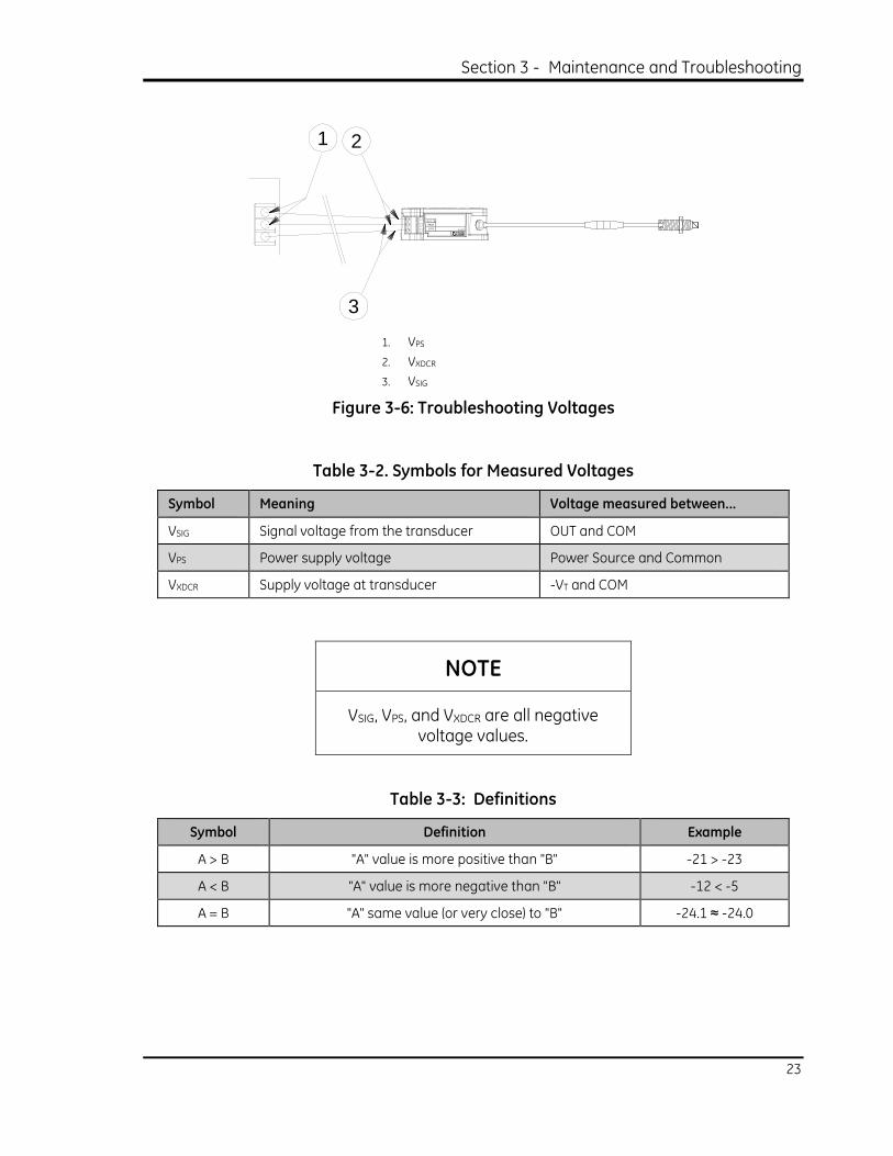
The troubleshooting procedures use measured voltages as shown in Figure 3-6, Table 3-2, and Table 3-3:
Section 3 - Maintenance and Troubleshooting
23
1 2
3
1. VPS 2. VXDCR 3. VSIG
Figure 3-6: Troubleshooting Voltages
Table 3-2. Symbols for Measured Voltages
Symbol Meaning Voltage measured between...
VSIG Signal voltage from the transducer OUT and COM
VPS Power supply voltage Power Source and Common
VXDCR Supply voltage at transducer -VT and COM
NOTE
VSIG, VPS, and VXDCR are all negative voltage values.
Table 3-3: Definitions
Symbol Definition Example
A > B "A" value is more positive than "B" -21 > -23
A < B "A" value is more negative than "B" -12 < -5
A = B "A" same value (or very close) to "B" -24.1 ≈ -24.0

3300 XL 8mm & 3300 5mm Proximity Transducer System
24
3.3 Fault Type 1: VXDCR > -17.5 Vdc or VXDCR < -26 Vdc Possible causes:
• Faulty power source
• Faulty field wiring
• Faulty Proximitor Sensor
1
1. VPS
Figure 3-7: Fault Type 1 Measurement 1
Measure VPS: Is VPS > -23 Vdc or VPS < -26 Vdc?
Yes: Faulty power supply.
No: Go to next step.
1
1. VXDCR
Figure 3-8: Fault Type 1 Measurement 2

Section 3 - Maintenance and Troubleshooting
25
Measure VXDCR: Is VXDCR > -23 Vdc or VXDCR < -26 Vdc?
Yes: Faulty Field wiring.
No: Faulty Proximitor Sensor.
3.4 Fault Type 2: VSIG = O Vdc Possible causes:
• Incorrect power source voltage
• Short circuit in field wiring
• Short circuit at Proximitor Sensor terminal connection
• Faulty Proximitor Sensor
Does fault condition type 1 exist?
Yes: Use the procedure for fault type 1
No: Go to the next step
1
1. VSIG
Figure 3-9: Fault Type 2 Measurement
Measure VSIG: Is VSIG = 0 Vdc?
No: Incorrect power source voltage or short in field wiring or short at Proximitor Sensor terminal connection.
Yes: Faulty Proximitor Sensor.

3300 XL 8mm & 3300 5mm Proximity Transducer System
26
3.5 Fault Type 3: -1 Vdc < VSIG < 0 Vdc Possible causes:
• Probe is incorrectly gapped (too close to target)
• Incorrect power source voltage
• Faulty Proximitor Sensor
• Probe is detecting other material than target (counter bore or machine case)
• Short or open circuit in a connector (dirty or wet) or loose connectors
• Short or open circuit in the probe
• Short or open circuit in extension cable
Does fault condition type 1 exist?
Yes: Use the procedure for fault type 1, see section 3.3.
No: Go to the next step
Is the probe gapped correctly? Are counter bore dimensions correct? (See section 2.1)
No: Regap the probe or check counter bore. Retest system.
Yes Go to the next step.
1
2
3
54
1. Step 1, disconnect original probe extension cable 2. Step 2, connect a known good probe and extension cable 3. Original probe extension cable 4. VSIG 5. Known good probe with correct length cable (open gap with probe
held away from conductive material
Figure 3-10: Fault Type 3 Measurement 1

Section 3 - Maintenance and Troubleshooting
27
Measurement 1: Is VSIG < VXDCR + 1 Vdc?
No: Faulty Proximitor Sensor
Yes: Go to next step
Figure 3-11: Fault Type 3 Measurement 2
Measurement 2: Inspect for clean connection-is the connection dirty, rusty, or a poor connection?
Yes: Clean the connector using isopropyl alcohol or electronic terminal cleaner, reassemble and retest the system.
No: Go to the next step.
1
1. RTOTAL
Figure 3-12: Fault type 3 Measurement 3

3300 XL 8mm & 3300 5mm Proximity Transducer System
28
Measurement 3: Measure resistance from center conductor to outer conductor. Is RTOTAL within specifications (see section 4.1)?
1 m system: 7.59 ± 0.50Ω
5 m system: 8.73 ± 0.70Ω
9 m System: 9.87 ± 0.90Ω
Yes: Reconnect and retest original system
No: Go to the next step
1
1. RPROBE
Figure 3-13: Fault Type 3 Measurement 4
Measurement 4: Measure resistance, RPROBE: Is RPROBE within specifications (see Table 4-1).
No: Faulty probe
Yes: Go to next step
1
2 1. RJACKET 2. RCORE
Figure 3-14: Fault Type 3 Measurement 5

Section 3 - Maintenance and Troubleshooting
29
Measurement 5: Measure resistance, RJACKET and RCORE: Is the resistance within specifications (see Table 4-2).
No: Faulty extension cable
Yes: Reconnect and retest the original system
3.6 Fault Type 4: VXDCR <VSIG < VXDCR + 2.5 Vdc Possible causes:
• Faulty Proximitor Sensor
• Probe is incorrectly gapped (too far from target)
Does fault condition type 1 exist?
Yes: Use the procedure for fault type 1 (see section 3.3)
No: Go to the next step
1
1. VSIG
Figure 3-15: Fault Type 4 Measurement
Disconnect probe extension cable, measure VSIG: Is –1.2 < VSIG < -0.3 Vdc?
No: Faulty Proximitor sensor
Yes: Reconnect the system. Regap the probe. Retest the system.

3300 XL 8mm & 3300 5mm Proximity Transducer System
30
3.7 Fault Type 5: VSIG = VXDCR Possible causes:
• Incorrect power source voltage
• Faulty Proximitor Sensor
• Faulty field wiring (between Out and VT)
Does fault condition type 1 exist?
Yes: Use the procedure for fault type 1 (see section 3.3)
No: Go to the next step
1
1. VSIG
Figure 3-16: Fault Type 5 Measurement
Disconnect the wire from the OUT terminal, measure VSIG: Is VSIG = VXDCR?
Yes: Faulty Proximitor Sensor
No: Faulty field wiring (short between Out and VT)
Bently Nevada performs failure analysis in Minden on returned transducers that are in warranty. We use the information gained during analysis of failed products to improve our current and future products. If you encounter a part that has failed, go to our website at www.gemeasurement.com and click on Services, then Bently Nevada Specific Services link. This will provide you with current information on how to obtain a Return Merchandise Authorization (RMA) number and how to return the part. If you do not have access to the internet, contact Technical support at: 1-775-215-1259 or toll-free (US) at 1-800-488-1915.

Section 4 - System Specifications
31
4. System Specifications For specifications, ordering information and performance graphs for a 3300 XL 8 mm system (Proximitor sensor, extension cable and probe), go to https://www.gemeasurement.com/sensors-probes-transducers/proximity-probes/bently-nevada-3300-xl-series-proximitor-system.
For specifications, ordering information and performance graphs for a 3300 5 mm system (Proximitor sensor, extension cable and probe), go to https://www.gemeasurement.com/sensors-probes-transducers/proximity-probes/bently-nevada-3300-proximitor-system.
For specifications and ordering information for a Bently Nevada precision micrometer, go to https://www.gemeasurement.com/sites/gemc.dev/files/precision_micrometers_datasheet_english.pdf.
Or contact your nearest Bently Nevada sales office or the BN Customer Service Department, Minden, Nevada, USA Phone: 1-775-215-1011 Fax: 1-775-215-2873.
4.1 Electrical Power
Requires -17.5 Vdc to -26 Vdc without barriers at 12 mA maximum consumption, -23 Vdc to -26 Vdc with barriers. Operation at a more positive voltage than -23.5 Vdc can result in reduced linear range.
Supply Sensitivity
Less than 2 mV change in output voltage per volt change in input voltage.

3300 XL 8mm & 3300 5mm Proximity Transducer System
32
Table 4-1: Probe Nominal DC Resistance (RPROBE)
Probe Length (Meters)
Resistance from the Center Conductor to the Outer Conductor (RPROBE) (ohms)
0.5 7.45 ± 0.50
1.0 7.59 ± 0.50
1.5 7.73 ± 0.50
2.0 7.88 ± 0.50
3.0 8.17 ± 0.60
5.0 8.73 ± 0.70
9.0 9.87 ± 0.90
Table 4-2: Extension Cable Nominal DC Resistance
Length of Extension Cable (Meters)
Resistance from Center Conductor to Center Conductor (RCORE) (ohms)
Resistance from Outer Conductor to Outer Conductor (RJACKET) (ohms)
3.0 0.66 ± 0.10 0.20 ± 0.04
3.5 0.77 ± 0.12 0.23 ± 0.05
4.0 0.88 ± 0.13 0.26 ± 0.05
4.5 0.99 ± 0.15 0.30 ± 0.06
6.0 1.32 ± 0.21 0.39 ± 0.08
7.0 1.54 ± 0.23 0.46 ± 0.09
7.5 1.65 ± 0.25 0.49 ± 0.10
8.0 1.76 ± 0.26 0.53 ± 0.11
8.5 1.87 ± 0.28 0.56 ± 0.11
Field wiring
0.2 to 1.5 mm2 (16 to 24 AWG). Recommend using three-conductor shielded triad cable. Maximum length of 305 metres (1,000 feet) between the 3300 XL Proximitor Sensor and the monitor. See the frequency and phase response graphs in datasheets for signal roll off at high frequencies when using longer field wiring lengths.

Section 4 - System Specifications
33
Linear Range
2mm (80 mils). Linear range begins at approximately 0.25mm (10 mils) from target and is from 0.25 to 2.3mm (10 to 90 mils) (approximately –1 to –17 Vdc).
Recommended Gap Setting for radial vibration
1.27mm (50 mils)
Incremental Scale Factor (ISF)
XL 8mm standard 5 or 1 metre system
7.87 V/mm (200 mV/mil) ±5% including interchangeability error when measured in increments of 0.25mm (10 mils) over the 80 mil linear range from 0 to +45°C (+32°F to +113°F).
XL 8mm standard 9 metre system
7.87 V/mm (200 mV/mil) ±6.5% including interchangeability error when measured in increments of 0.25mm (10 mils) over the 80 mil linear range from 0 to +45°C (+32°F to +113°F).
3300 5mm standard 1, 5 and 9 metre systems
7.87 V/mm (200 mV/mil) ±6.5% typical, including interchangeability error when measured in increments of 0.25mm (10 mils) over the linear range.
Extended Temperature Range (ETR) 5 and 9 metre systems
7.87 V/mm (200 mV/mil) ±6.5% including interchangeability error when measured in increments of 0.25mm (10 mils) over the 80 mil linear range from 0 to +45°C (+32°F to +113°F).

3300 XL 8mm & 3300 5mm Proximity Transducer System
34
Deviation from best fit straight line (DSL)
XL 8mm standard 1 or 5 metre system
Less than ±0.025mm (±1 mil) with components at 0°C to +45°C (+32°F to +113°F).
XL 8mm standard 9 metre system:
Less than ±0.038mm (±1.5 mil) with components at 0°C to +45°C (+32°F to +113°F).
3300 5mm standard 1, 5 and 9 metre systems
Less than ±0.038mm (±1.5 mil) with components at +18°C to +27°C (+64°F to +80°F)
Extended Temperature Range 5 and 9 metre systems
Less than ±0.038mm (±1.5 mil) with components at 0°C to +45°C (+32°F to +113°F).
Minimum Target Size
15.2mm (0.6 in.) diameter (flat target)

Section 4 - System Specifications
35
Shaft Diameter
When gapped at the center of the linear range, the interaction between two separate transducer systems (cross-talk) will be less than 50 mV on shaft diameters between 50 mm (2 in.) and 76.2mm (3 in.). You should take care to maintain minimum separation of transducer tips, generally at least 40mm (1.6 in.) for axial position measurements or 38mm (1.5 in.) for radial vibration measurements to limit cross talk to 50 mV or less. Radial vibration or position measurements on shaft diameters smaller than 76.2mm (3 in) will generally change the scale factor.
Minimum
50.8mm (2 in.)
Recommended minimum
76.2mm (3 in.)
Table 4-3: Probe Case Torque Specifications
Probe case torque: Maximum Rated Recommended
Standard forward-mounted XL 8mm probes (3/8-24, M10x1)
33.9 N•m (300 in•lbf)
11.2 N•m (100 in•lbf)
Standard forward-mounted 3300 probes (1/4-28, M8x1)
7.3 N•m (65 in•lbf)
5.1 N•m (45 in•lbf)
Standard forward-mount XL 8mm probes - first three threads (3/8-24, M10x1)
22.6 N•m (200 in•lbf)
7.5 N•m (66 in•lbf)
Reverse mount probes 22.6 N•m
(200 in•lbf) 7.5 N•m
(66 in•lbf)
Connector-to-connector torque
See Table 4-4 for recommended torque.

3300 XL 8mm & 3300 5mm Proximity Transducer System
36
Table 4-4: Recommended Connector-to-Connector Torque
Connector Type Tightening Instructions
Two 3300 XL gold "click" type connectors Finger tight
One non-XL stainless steel connector and one 3300 XL connector Finger tight plus 1/8 turn using pliers
Maximum connector torque
0.565 N•m (5 in•lbf)
Minimum cable bend radius
25.4mm (1.0 in.)
4.2 Environmental Limits
4.2.1 Probe Temperature Range
Operating and Storage Temperature
Standard probe
-51°C to +177°C (-60°F to +351°F)
Extended Temperature Range
Probe tip
-51°C to +218°C (-60°F to +425°F)
Probe cable and connector
-51°C to +260°C (-60°F to +500°F)
NOTE
Exposing the probe to temperatures below –34°C (-30°F) may cause
premature failure of the pressure seal.

Section 4 - System Specifications
37
Probe Pressure
3300 XL 8mm and 3300 5mm probes are designed to seal differential pressure between the probe tip and case. The probe sealing material consists of a Fluorocarbon O-ring. Probes are not pressure tested prior to shipment. Contact our custom design department if you require a test of the pressure seal for your application.
Application Advisory
It is the responsibility of the customer or user to ensure that all liquids and gases
are contained and safely controlled should leakage occur from a proximity
probe. In addition, solutions with high or low pH values may erode the tip
assembly of the probe causing media leakage into surrounding areas. Bently Nevada Inc. will not be held responsible for any damages resulting from leaking 3300 XL 8mm or 3300 5mm proximity probes. In addition, 3300 XL 8mm or
3300 5mm proximity probes will not be replaced under the service plan due to
probe leakage.
4.2.2 Extension Cable Temperature Range
Operating and Storage Temperature
Standard cable
-51°C to +177°C (-60°F to +351°F)
Extended Temperature Range cable
-51°C to +260°C (-60°F to +500°F)

3300 XL 8mm & 3300 5mm Proximity Transducer System
38
4.2.3 Proximitor Sensor Temperature Range
Operating Temperature
-51°C to +100°C (-60°F to +212°F)
Storage Temperature
-51°C to +105°C (-60°F to +221°F)
Relative Humidity
Less than a 3% change in Average Scale Factor (ASF) when tested in 93% humidity in accordance with IEC standard 68-2-3 for up to 56 days.

Section 5 - System Dimensional Drawings
39
5. System Dimensional Drawings 5.1 3300 XL 8mm Proximity Probes, Standard Mount
2.5 (0.10)
2
1
4
5
7
89
6
10
3
1. 8.0mm (0.31 in.) diameter probe tip 2. 9/16 in. for 3/8-24 threads2; M17 for M10X1 threads2 3. Case threads, 3/8-24 or M10X1 4. 5/16 in. wrench flats for 3/8-24 threads; 8mm wrench flats for M10X1 threads 5. 75Ω cable
3.68mm (0.145 in.) maximum outside diameter 3.94mm (0.155 in.) maximum diameter for FluidLoc cable 7.67mm (0.302 in.) maximum outside diameter for armor 9.50mm (0.380 in.) maximum diameter for armor ferrule
6. Miniature male coaxial connector, 7.24mm (0.285 in.) maximum outside diameter, no connector protector 12.4mm (0.49 in.) outside diameter with connector protector
7. Unthreaded length, as ordered 8. Case length, as ordered 9. Probe tip, 6.00mm (0.24 in.) maximum 10. Total length4, as ordered, +30%, -0%
Figure 5-1: 3300 XL 8mm Proximity Probes, Standard Mount
330101 and 330191, 3/8-24 UNF-2A, without armor 8
330102 and 330192, 3/8-24 UNF-2A, with armor 7
330103 and 330193, M10X1 thread, without armor 8
330104 and 330194, M10X1 thread, with armor 7

3300 XL 8mm & 3300 5mm Proximity Transducer System
40
5.2 3300 5mm Proximity Probes
3.2 (0.13)
2
1
4
5
7
89
6
10
3
1. 5.2mm (0.21 in.) diameter probe tip 2. 7/16 in. for 1/4-28 threads3; M13 for M8X1 threads3 3. Case threads, 1/4-28 or M8X1 4. 7/32 in. wrench flats for 1/4-28 threads, 7.0mm for M8X1 threads 5. 75Ω cable
2.84mm (0.112 in.) maximum outside diameter for cable 7.67mm (0.302 in.) maximum outside diameter for armor 10.20mm (0.400 in.) maximum diameter for armor ferrule
6. Miniature male coaxial connector, 7.24mm (0.285 in.) maximum outside diameter, no connector protector 12.4mm (0.49 in.) outside diameter with connector protector
7. Unthreaded length, as ordered 8. Case length, as ordered 9. Probe tip, 6.00mm (0.24 in.) maximum 10. Total length4, as ordered, +30%, -0%
Figure 5-2: 3300 5mm Proximity Probes
330171, 1/4-28 UNF-2A, without armor 8
330172, 1/4-28 UNF-2A, with armor 7
330173, M8X1 thread, without armor 8
330174, M8X1 thread, with armor 7

Section 5 - System Dimensional Drawings
41
5.3 3300 XL 8mm Proximity Probes, Reverse Mount
12 3
4
85
9
1011
67
1. 8.0mm (0.31 in.) nominal diameter probe tip 2. 7/16 in. for 3/8-24 threads or M10 hexagonal for M10X1 threads 3. Case thread, 3/8-24 or M10x1 4. 75Ω cable, 3.68mm (0.145 in.) maximum outside diameter 5. Miniature male coaxial connector, 7.24mm (0.285 in.) maximum outside
diameter 6. Thread relief 2.3mm (0.09 in.) 7. Wrench flat width, 5.1mm (0.20 in.) 8. Unthreaded length, 5.1mm (0.20 in.) 9. Case length, 30.5mm (1.2 in.) 10. Probe tip, 6.0mm (0.24 in.) Maximum 11. Total length4, as ordered, +30%, -0%
Figure 5-3: 3300 XL 8mm Proximity Probes, Reverse Mount 5, 8
330105 and 330195, 3/8-24 UNF-2A threads
330106 and 330196, M10X1 threads

3300 XL 8mm & 3300 5mm Proximity Transducer System
42
5.4 3300 XL 8mm Proximity Probes, Smooth Case
2.54 (0.100)
12 3
4
5
68
7
9
1. 8.0mm (0.31 in.) diameter probe tip 2. Case diameter, 9.66mm (0.38 in.) maximum 3. 5/16 in. wrench flats, 4 each 4. 75Ω cable, 3.68mm (0.145 in.) maximum diameter
3.94mm (0.155 in.) maximum diameter for FluidLoc cable 7.67mm (0.302 in.) maximum outside diameter for armor 10.2mm (0.40 in.) maximum diameter for armor ferrule
5. Miniature male coaxial connector, 7.24mm (0.285 in.) maximum outside diameter
6. Case length, as ordered 7. Label location, 349.3mm (13.750 in.) maximum 8. Probe tip, 6.0mm (0.235 in.) maximum 9. Cable length4, as ordered, +30%, -0%
Figure 5-4: 3300 XL 8mm Proximity Probes, Smooth Case
330140 and 330197, without armor 8
330141 and 330198, with armor 7

Section 5 - System Dimensional Drawings
43
5.5 Extension Cable
(3.30)83.8
(3.30)83.8
(3.30)83.883.8
(3.30)
1
2
3
45
67
8
9
1. 7.24mm (0.285 in.) maximum diameter 2. Miniature male coaxial connector 3. FEP or PFA coated armor7, armor length 300mm (11.8 in.) less than cable length 4. 75Ω cable, 3.68mm (0.145 in.) maximum outside diameter
3.94mm (0.155 in.) maximum diameter for FluidLoc cable 7.67mm (0.302 in.) outside diameter for armor
5. 7.24mm (0.285 in.) maximum diameter 6. Stainless steel ferrules, 10.2mm (0.40 in.) maximum diameter 7. FEP or PFA insulated triaxial cable 8. Miniature female coaxial connector 9. Cable length, as ordered, +20%, -0%
Figure 5-5: 330130, 3300 XL Extension Cable (FEP armor and insulation) 330190, 3300 XL ETR Extension Cable (PFA armor and insulation)
5.6 Extension Cable with Connector Protectors
1
5
432
1. 12.4mm (0.49 in.) diameter maximum 2. 36.3mm (1.43 in.) maximum 3. 51.0mm (2.01 in.) maximum 4. 12.4mm (0.49 in.) diameter maximum 5. Connector protector (fluorosilicone material) only installed on female
end when optioned. Both ends available as accessories.
Figure 5-6: 3300 XL Extension Cable with Connector Protectors Installed

3300 XL 8mm & 3300 5mm Proximity Transducer System
44
5.7 Proximitor Sensor See Figure 2-6 and Figure 2-7.
50
25.4
(1.95)
50.8(2.00)
61.4(2.42)
50.8(2.00)
79.4(3.125)
(1.00)
R
86(3.4)
63.5
50.8(2.00)
81.3(3.20)
50.8(2.00)
61.0(2.40)
5.1(0.20)
(2.50)
(3.2)81
1
1. Total Length & Mounting options, -10, -50 or -90
Figure 5-7: Physical mounting characteristics showing interchangeability of 3300 and 3300 XL Proximitor Sensors when 4-hole mounting option is used9

Section 5 - System Dimensional Drawings
45
Notes:
1. All dimensions on figures are in millimeters (inches) unless otherwise noted.
2. Standard mount 8mm probes supplied with 17mm or 9/16 inch lock nut.
3. Standard mount 5mm probes supplied with 13mm or 7/16 inch lock nut.
4. Probes ordered with 5 or 9 meter integral cables have a length tolerance of +20%, -0%.
5. Reverse mount probes not available with armor or connector protector options.
6. Letters inside quotation marks on figures refer to probe ordering options.
7. Stainless steel armor is supplied with FEP outer jacket for standard probes, PFA outer jacket for ETR probes.
8. FEP jacket is standard non-armored portion of the cable for standard probes, PFA jacket on non-armored portion for ETR probes.
9. Use M3.5 or #6 screws for panel-mount Proximitor Sensors (screws provided when purchasing Bently Nevada housings).

3300 XL 8mm & 3300 5mm Proximity Transducer System
46

Section 6 - Index
47
6. Index
A
advisory probe leakage .............................................39 target size ....................................................... 7
API 670 .......................................................... iii, 24
B
backlash ..................................................... 19, 21
C
cable bend radius ..................................................37
ClickLoc ................................................................. 2 connector
extended temperature .............................. 3 protectors .....................................................14 silicone tape ............................................ 3, 13 tightening .............................................. 13, 37
crosstalk ............................................................... 7
D
definitions .................................................... iii, 25 ASF (Average Scale Factor) ...................23 DSL (Deviation Straight Line) ........ 23, 35 ISF (Incremental Scale Factor) ..... 23, 34
dimensions .......................................................... 9 counter-bore ...............................................28 mounting ......................................................... 9 probe ................................................................. 5
disposal ................................................................ iv
E
error ......................................................... 7, 34, 35 extension cable
resistance ............................................. 30, 34
F
field wiring .........................................................34 fluidloc .................................................. 41, 44, 45
G
gap setting ........................................................ 34
H
humidity .............................................................. 40
L
linear range ....................................................... 34
M
micrometer ................................ 18, 19, 20, 33 part number................................................. 24
N
notes crosstalk noise .............................................. 7 general ...................................................... 3, 47 hazardous area .......................................... 18 micrometer .......................................... 19, 21 pressure seal ............................................... 38 voltage polarity .......................................... 25
NSv ................................................................... 3, 24
P
power input ....................................................... 33 probe
pressure seal ....................................... 14, 38 resistance ............................................. 30, 33
R
runout ............................................................ iii, 24
S
size minimum target ......................................... 36 shaft diameter ............................................ 36
supply sensitivity ............................................ 33 symbols ......................................................... iv, 25

3300 XL 8mm & 3300 5mm Proximity Transducer System
48
T
terminal strips, SpringLoc ............................. 2 TipLoc..................................................................... 2
Z
zero ........................................................ 19, 20, 21