Bending Stress - University of...
19
Beam Deflction Page A1 Using Tables for Formulas to Find Beam Deflection, y (pages 734 – 742) General machine part Keep y max below 0.0005 in/in of length Page 459 Or check for interference with other machine parts 90-1, 9-6- Page 515 Round, steel shaft, diameter 32mm, 700mm long 3.0 kN load Simply supported at ends – find deflection at center 734 9-1 load at center – figure (a) y max = − PL 3 48 EI 9-6 load 175 mm from left support – figure (b) y= −Pbx 6 EIL ( L 2 −b 2 −x 2 )
Transcript of Bending Stress - University of...

Beam Deflction Page A1
Using Tables for Formulas to Find Beam Deflection, y (pages 734 – 742)
General machine partKeep ymax below 0.0005 in/in of length Page 459Or check for interference with other machine partsCases not in appendix, use Roark (BB, Web Resources, must be on campus or VPN)
90-1, 9-6- Page 515Round, steel shaft, diameter 32mm, 700mm long3.0 kN loadSimply supported at ends – find deflection at center9-1 load in center9-6 load 175mm from left support
Page 734
9-1 load at center – figure (a)
ymax=−PL3
48 E I
9-6 load 175 mm from left support – figure (b)
y=−Pbx6 EIL
(L2−b2−x2)
FE
24kN
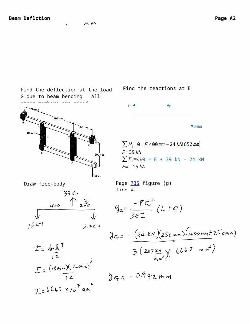
Beam Deflction Page A2
∑M E=0=F ( 400mm )−24 kN (650mm )F=39 kN∑ F y=¿¿0 = E + 39 kN – 24 kNE=−15kN
Find the deflection at the load G due to beam bending. All other members are rigid.Steel, 20mm tall, 10 mm wide.
Page 735 figure (g) find yG
Find the reactions at E and F
Draw free-body diagram

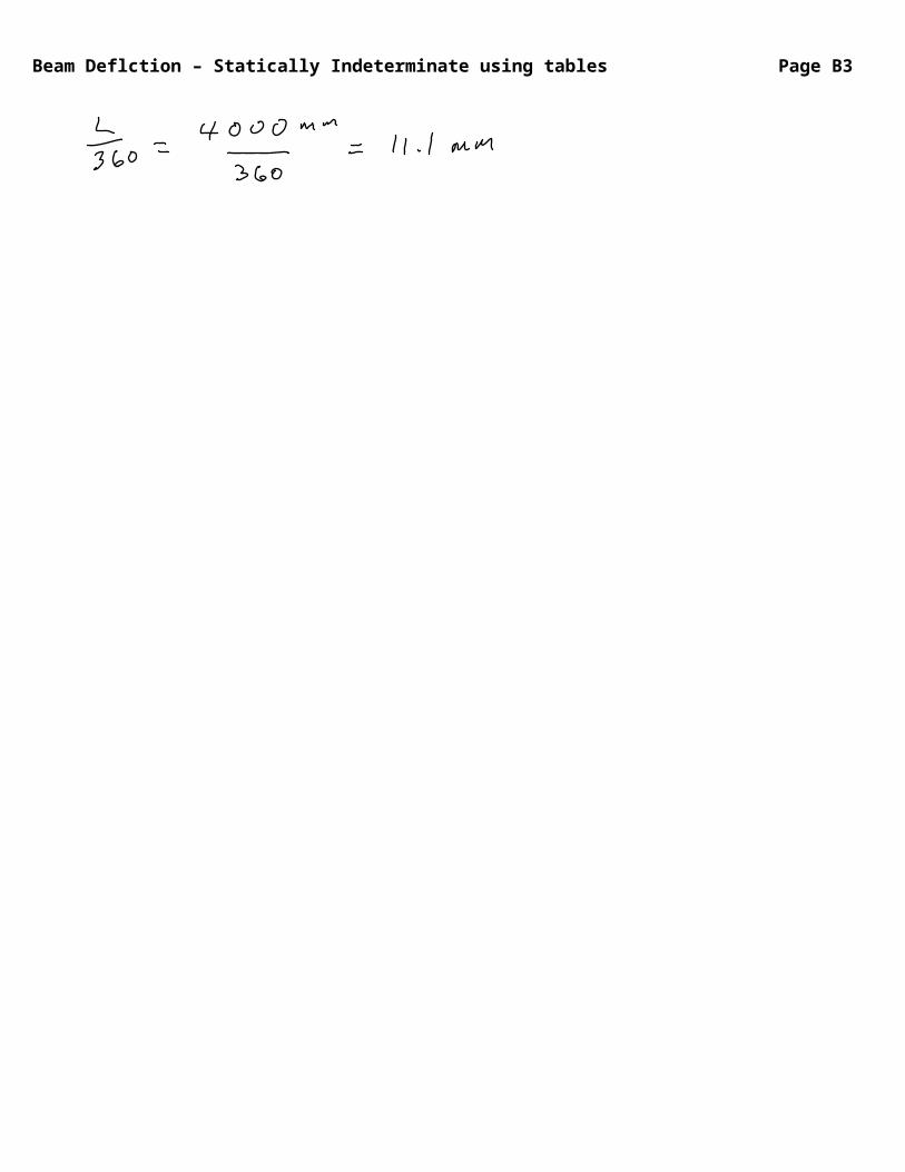
Beam Deflction – Statically Indeterminate using tables Page B1
Must use deformation properties to find reactions
Page 516 9-27Use A-25(f) with P = 35 kN, L = 4.0 m, a = 2.50 mFind reactionsDraw shear and moment diagramGive maximum V with x and maximum M with xGive maximum deflectionSelect material and cross-section shape for static loadingConfirm deflection less than L/360
Page 740
RA=Pb2
L3 (3a+b)
RC=Pa2
L3 (3b+a)
M A=−Pab2
L2 M B=2 Pa2b2
L3
MC=−Pa2bL2

Beam Deflction – Statically Indeterminate using tables Page B2
Check ymax E = 207 kN/mm2
ymax=−2Pa3b2
3EI (3a+b)2
Choose steel, assume structure, building Wshape, try Sy 296 MPA 1020 cold drawnFind S for M
Check V page 437
page 723 701 714

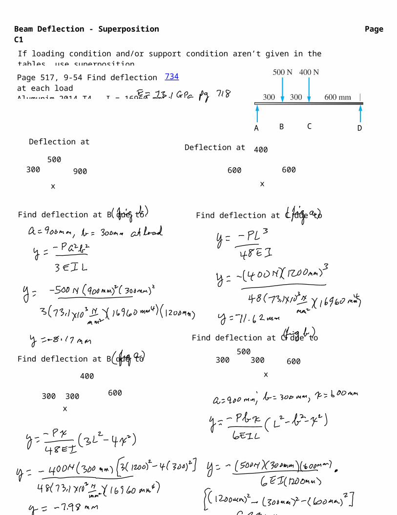
Beam Deflection - Superposition Page C1If loading condition and/or support condition aren’t given in the tables, use superposition.Method: break conditions into separate sketches of know table deflectionsPage 517, 9-54 Find deflection at each loadAlumunim 2014-T4, I = 16960 mm4
Find deflection at B due to B
A B C D
Find deflection at B due to C
Find deflection at C due to C
Find deflection at C due to B
300 900 600 600500
400
Page 734
x x
300 300500
x
600
600
400
x300 300
Deflection at B Deflection at C
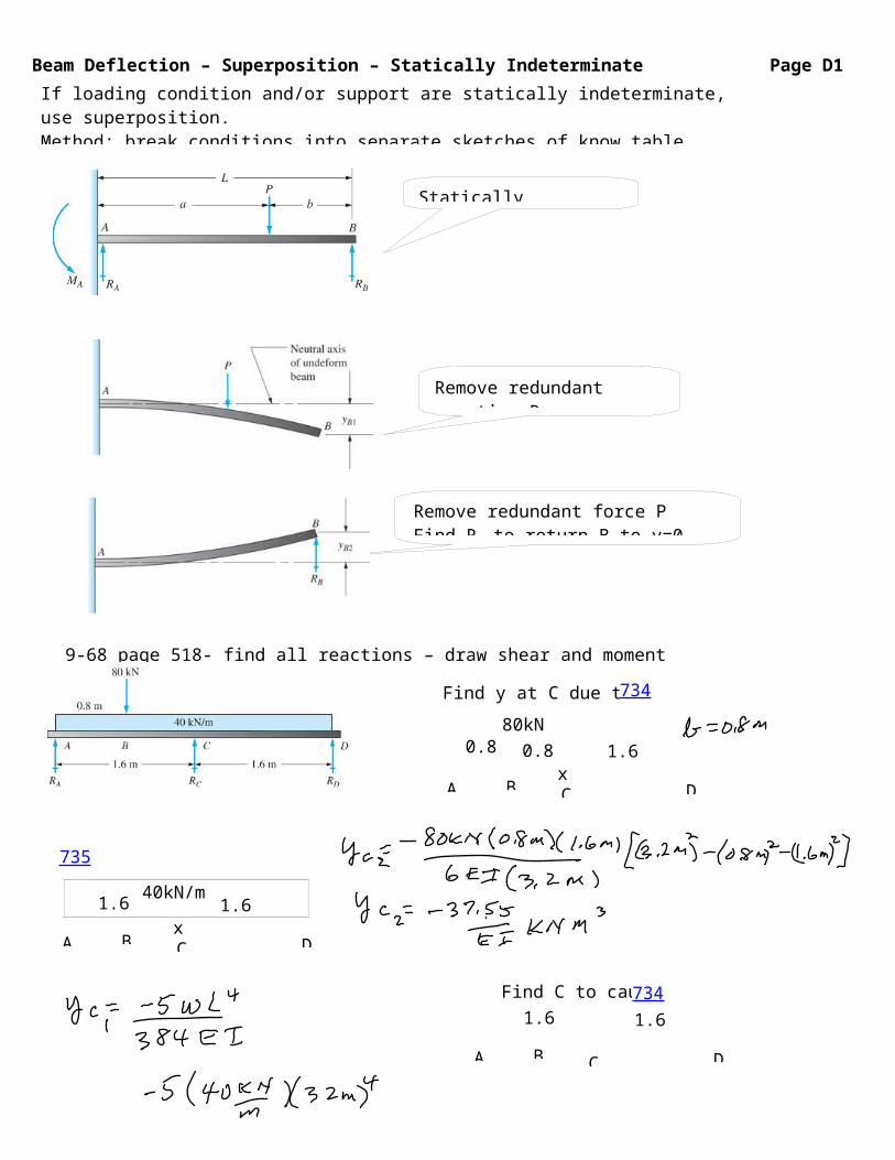
Beam Deflection – Superposition – Statically Indeterminate Page D1If loading condition and/or support are statically indeterminate, use superposition.Method: break conditions into separate sketches of know table deflections Solve each sketch. Apply constraint conditions to the y values
Statically Indeterminate
Remove redundant reaction RB
Find y at location B
Remove redundant force PFind RB to return B to y=0 constraint
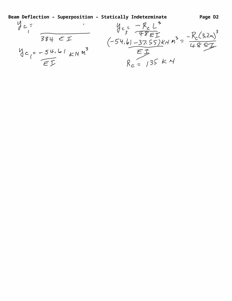
9-68 page 518- find all reactions – draw shear and moment diagrams.
1.60.8x
A
80kN0.8
B C D
Find y at C due to 80kN Page 734
1.61.6
A B C D
Find C to cause y
Find y at C due to 40kN/m Pg 735
1.61.6x
A
40kN/m
B C D
Page 734
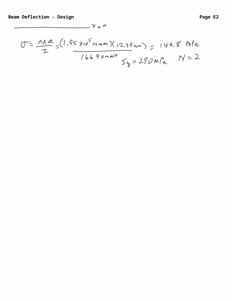
Beam Deflection - Design Page E1
Recommended Deflection Limits (page 459)General machine parts
Moderate precision
High precision
Or use company standards or codesOr check for interference with other machine parts
Absent any recommendation use Where L = length between spans or total length
ymaxL
=0.000 5 ¿0.003ymaxL
=0.00001¿0.0005ymaxL
=0.000 001 ¿0.000 01
Check previous problems for precision
ymax<L
360
Beam Deflection – Successive Integration Page F1
∫V 0
V
dV=∫x0
x
−wdx
∫M 0
M
dM=∫x0
x
V dx
θEI=∫x0
x
Mdx
yEI=∫x0
x
θEIdx
θ = slope, y = deflection
9-82 (use E = 69 GPa, I = 1.79x107 mm4 EI = 1235 kNm)Find the maximum deflection in the beam.
1R
=d2 ydx2 =M
EI
∫Mdx=EI∫ d2 ydx2 dx
∫Mdx=EI∫ dydx
=EIθ
∫EI θ dx=EI∫ dydxdx=EIy
Pages 484-486
Beam Deflection – Successive Integration Page F2
AB, x = 0 m– 0.4 m
V=
∫M 0
M
dM=∫x0
x
V dx
M(x) =
θEI=∫Mdx
θEI ( x )=¿
yEI=∫θEIdx
yEI ( x )=¿
BC, x = 0.4 m– 1.2 m
V=
∫M 0
M
dM=∫x0
x
V dx
M(x) =
θEI=∫Mdx
θEI ( x )=¿
yEI=∫θEIdx
yEI ( x )=¿
Write equation and solve Find ymax where θEI=0Assume in BC and confirm
C1 = -10.58 C4= 0.22C3= -12.18 C5= -33.82
C6 = 8.94
/CD, x = 1.2 m– 2 m
V=
∫M 0
M
dM=∫x0
x
V dx
M(x) =
θEI=∫Mdx
θEI ( x )=¿
yEI=∫θEIdx
yEI ( x )=¿
AB BC CD
Write equations and solve
Beam Deflection – Moment Area Method Page G1
Use Moment-Area Method for complex loading and/or changing cross sections
Page 498
Page 500

Beam Deflection – Moment Area Method Page G2
9-94
Beam Deflection – Moment Area Method Page G3

Beam Deflection – Moment Area Method Page G4


![Chapter 1[1].mmii](https://static.fdocuments.in/doc/165x107/55528c63b4c9051f108b466a/chapter-11mmii.jpg)