
Bending Behavior of Steel Circular Hollow Sections with ...
11
612 Prof. Dr. Amer Mohammed Association of Arab Universities Journal of Engineering Sciences Manahel Shahath Khalaf NO. 3 Volume. 24 Year. 2017 Bending Behavior of Steel Circular Hollow Sections with Openings Manahel Shahath Khalaf Email. [email protected] University of Diyala Amer Mohammed Ibrahim Pro. Dr., Engineering College, University of Diyala Diyala/Iraq Abstract:- Steel circular hollow sections have been widely used in many engineering applications as a structural members. This paper presents a study about the bending behavior of circular steel tubes through a series of bending tests in order to study and examine the influence of presence of openings on the structural behavior and the bending properties of these sections. The experimental program comprised testing of four specimens with diameter, thickness and length equal to 101.6, 3 and 1500 mm respectively. The tested steel specimens having yield stress of 290 MPa and the ultimate stress of 350 MPa. The results of the experimental work showed that the presence of openings in the specimens reduced their stiffness and ductility significantly and effected on the structural collapse of these specimens. In addition, the presence of one, two or three openings in the pure bending region of the specimens didn’t effect on their yield and ultimate strength capacity. 1. Introduction In recent years, Steel Circular Hollow sections (CHS) use increased significantly in many applications such as structural, architectural and mechanical engineering. The circular hollow sections have many excellent structural characteristics especially with regard to their resistance for torsion, bending and compression loadings in different directions as a result of the uniform distribution of the steel about the neutral axis, which leads to good performance of these sections [2]. In addition, the closed shape for these sections and absence of the sharp corners give best protection against corrosion and thus reduce the costs of protection compared with the open sections [1, 3, 6]. The multi-storey buildings are imposed by the limitations of height depending on the zoning regulations, economic consideration and the esthetic and functional requirements that meet the needs of these buildings. The ability to meet these requirements is an important consideration in the building or framing system selection [4, 5].
Transcript of Bending Behavior of Steel Circular Hollow Sections with ...

612
Prof. Dr. Amer Mohammed Association of Arab Universities Journal of Engineering Sciences Manahel Shahath Khalaf NO. 3 Volume. 24 Year. 2017
Bending Behavior of Steel Circular Hollow Sections with
Openings
Manahel Shahath Khalaf
Email. [email protected]
University of Diyala
Amer Mohammed Ibrahim
Pro. Dr., Engineering College, University of Diyala
Diyala/Iraq
Abstract:-
Steel circular hollow sections have been widely used in many engineering applications as
a structural members. This paper presents a study about the bending behavior of circular
steel tubes through a series of bending tests in order to study and examine the influence of
presence of openings on the structural behavior and the bending properties of these
sections. The experimental program comprised testing of four specimens with diameter,
thickness and length equal to 101.6, 3 and 1500 mm respectively. The tested steel
specimens having yield stress of 290 MPa and the ultimate stress of 350 MPa. The results
of the experimental work showed that the presence of openings in the specimens reduced
their stiffness and ductility significantly and effected on the structural collapse of these
specimens. In addition, the presence of one, two or three openings in the pure bending
region of the specimens didn’t effect on their yield and ultimate strength capacity.
1. Introduction
In recent years, Steel Circular
Hollow sections (CHS) use
increased significantly in many
applications such as structural,
architectural and mechanical
engineering. The circular hollow
sections have many excellent
structural characteristics especially
with regard to their resistance for
torsion, bending and compression
loadings in different directions as a
result of the uniform distribution of
the steel about the neutral axis,
which leads to good performance of
these sections [2]. In addition, the
closed shape for these sections and
absence of the sharp corners give
best protection against corrosion and
thus reduce the costs of protection
compared with the open sections [1,
3, 6].
The multi-storey buildings are
imposed by the limitations of height
depending on the zoning regulations,
economic consideration and the
esthetic and functional requirements
that meet the needs of these
buildings. The ability to meet these
requirements is an important
consideration in the building or
framing system selection [4, 5].

612
Prof. Dr. Amer Mohammed Association of Arab Universities Journal of Engineering Sciences Manahel Shahath Khalaf NO. 3 Volume. 24 Year. 2017
Provision of openings in structural
steel beams becomes necessary for
passing the utilities through beams
such as the air conditioning and
pipelines and thus help to reduce the
storey height. A reduction of
building height decreases the
external surface and internal volume
of the buildings, which leads to
reduce the costs of operation and
maintenance as well as the
construction costs therefore, the
provision of beams with openings
becomes an acceptable in the
practices of engineering and
eliminates the probability of working
holes in the inappropriate places.
To study the bending behavior of
steel circular hollow specimens, four
simply supported specimens has
been tested in this study. For these
four specimens, the pure bending is
generated between two loading
points. These specimens were used
with same length, diameter and
thickness but the main variable was
the number and the presence
locations of the openings along the
specimens as listed in Table 1. All
openings in the specimens were
square shape and with rib length
equal to 50 mm as shown in Fig 1.
Table 1. Dimensions of the specimens
Fig 1. Specimens BT1, BT4, BT5 and
BT6.
2. Experimental study:
2.1 Circular hollow specimens
In this experimental work, it was
necessary to make special
circumstances at the loading points
in order to improve the specimen
bending capacity and prevent the
early appearance of the local
buckling at the specimen loading
points. Therefore, four machined
Spec.
designation
t
(mm)
D
(mm)
L
(mm) Opening description
BT1 3 101.6 1500 Without openings
BT4 3 101.6 1500 With one opening at the specimen center
BT5 3 101.6 1500 With two openings at the specimen loading
points
BT6 3 101.6 1500 With three openings at the specimen center and
loading points

612
Prof. Dr. Amer Mohammed Association of Arab Universities Journal of Engineering Sciences Manahel Shahath Khalaf NO. 3 Volume. 24 Year. 2017
rings were used at supports and
loading points locations.
2.2 Experimental setup
The setup of the tested specimens is
shown in Fig 2, the specimen was
placed between two supports and the
vertical load was applied in the
center of the specimen by using the
hydraulic jack. This load was
transferred equally to the specimen
loading points through the spreader
beam.
Three dial gauges with accurately
0.01 mm were used for measuring
the vertical displacement at various
locations. One of these dial gauges
was put at the mid-span section
while the remaining dial gauges
were put at the loading points.
Fig 2. Schematic view of the test device and dial gauges distribution
3. Experimental results:
3.1 Load-Deflection curve of test
specimens
From Fig. 3 it could be noted that
the tested specimens went through
different stages when loaded
gradually and which are as follows:
1- The elastic stage:
For the specimens BT1, BT4, BT5
and BT6, the elastic stage started
from the beginning of loading to
yield load equaled to 45, 40, 41 and
40 kN respectively and is
characterized by linear relationship
between the applied load and the
specimen deflection.
In this stage, all specimens have
very similar behavior with very
close values of the yield load and
yield deflection as shown in Fig 3.
From this Fig, it can be noted that
the presence of openings in the
specimens didn’t have significant
effect on the elastic stage for these
specimens.
2- The ovalisation stage:
This stage represents the beginning
of the specimen plastic behavior.
612
Prof. Dr. Amer Mohammed Association of Arab Universities Journal of Engineering Sciences Manahel Shahath Khalaf NO. 3 Volume. 24 Year. 2017
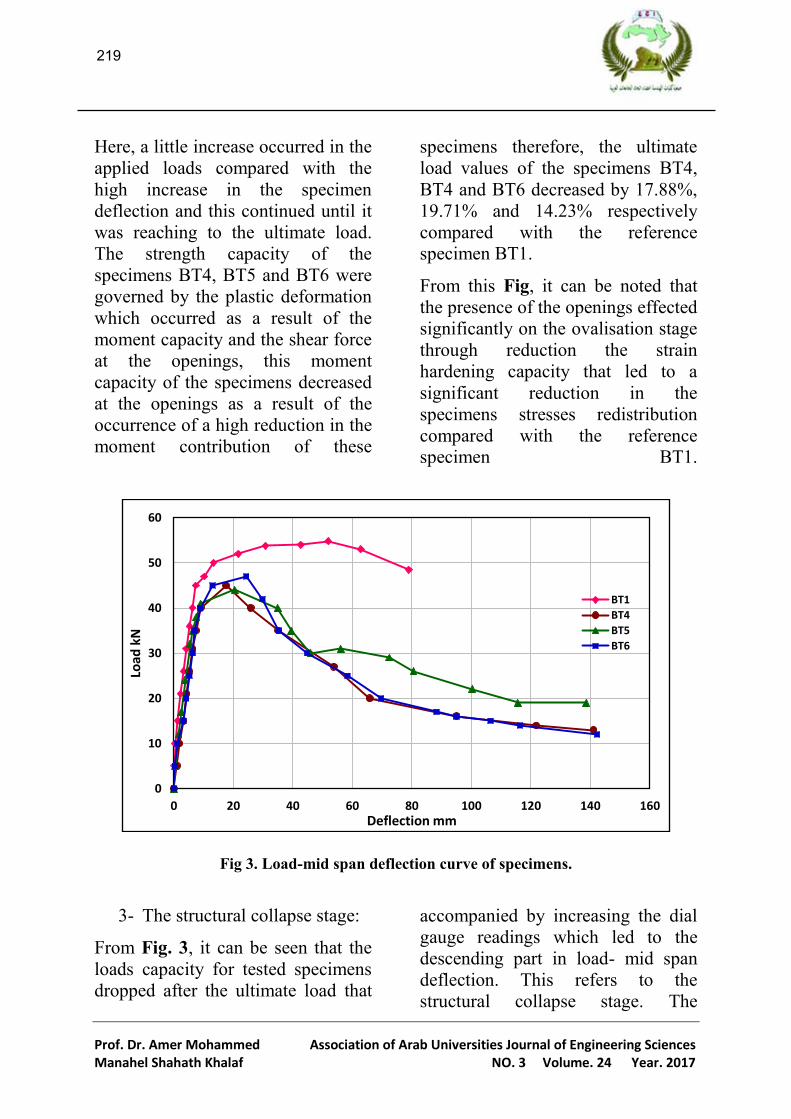
Here, a little increase occurred in the
applied loads compared with the
high increase in the specimen
deflection and this continued until it
was reaching to the ultimate load.
The strength capacity of the
specimens BT4, BT5 and BT6 were
governed by the plastic deformation
which occurred as a result of the
moment capacity and the shear force
at the openings, this moment
capacity of the specimens decreased
at the openings as a result of the
occurrence of a high reduction in the
moment contribution of these
specimens therefore, the ultimate
load values of the specimens BT4,
BT4 and BT6 decreased by 17.88%,
19.71% and 14.23% respectively
compared with the reference
specimen BT1.
From this Fig, it can be noted that
the presence of the openings effected
significantly on the ovalisation stage
through reduction the strain
hardening capacity that led to a
significant reduction in the
specimens stresses redistribution
compared with the reference
specimen BT1.
Fig 3. Load-mid span deflection curve of specimens.
3- The structural collapse stage:
From Fig. 3, it can be seen that the
loads capacity for tested specimens
dropped after the ultimate load that
accompanied by increasing the dial
gauge readings which led to the
descending part in load- mid span
deflection. This refers to the
structural collapse stage. The
0
10
20
30
40
50
60
0 20 40 60 80 100 120 140 160
Load
kN
Deflection mm
BT1
BT4
BT5
BT6

662
Prof. Dr. Amer Mohammed Association of Arab Universities Journal of Engineering Sciences Manahel Shahath Khalaf NO. 3 Volume. 24 Year. 2017
collapse of the reference specimen
BT1 began through very smooth
kink forming in the compression part
at pure bending region. Continuation
the specimen loading worked to
increase its deflection and gradual
growth of this kink and thus caused
the local buckling at the specimen
top surface. This local buckling
effected on the entire specimen and
led to the formation of two folds,
one of them at the top surface and
exposure to compression
deformation and the other in bottom
surface and exposure to tension
deformation, finally this led to the
global buckling failure mode as
shown in Fig. 4.
This stage began when the arrival of
the specimens BT4, BT5 and BT6 to
the ultimate load by exposure all
specimen elements that situated
above and below the opening to high
stresses. The specimen elements
below the openings are exposed to
tension stress which led to the
occurrence of yielding, while the
elements above the openings are
exposed to compression stress and
this led to the occurrence of
buckling.
The collapse of the specimen BT4
began by the occurrence of high
plastification at the top surface of the
openings as a result of exposure to a
high compression which led to the
kink formation in this surface while
continuing to apply loads.
After that, this kink has evolved into
the local buckling and moved from
the top surface of the opening to the
top surface of the specimen causing
the formation of two folds, one in
the top surface and the other in the
bottom surface and finally led to the
global buckling failure mode as
shown in Fig. 5.
Fig 4. Structural failure of the specimen BT1.
While the collapse of the specimen
BT5 began by the fold formation in
the top surface of the specimen at
opening in the left loading point.

661
Prof. Dr. Amer Mohammed Association of Arab Universities Journal of Engineering Sciences Manahel Shahath Khalaf NO. 3 Volume. 24 Year. 2017
The continuation of the specimen
loading after the ultimate load has
led to increase the amplitude and
height of the fold without the
occurrence of transmission to other
places as shown in Fig. 6. Finally,
this fold caused the local buckling
failure in the specimen compression
part.
The collapse of the specimen BT6
began by exposure the top surface of
the central opening to large
compression accompanied by a large
deformation as a result of the
occurrence of yielding which
followed by buckling. Continuing to
apply loads on this specimen caused
the local buckling formation and
after that moved from the central
opening to the specimen top surface,
causing the formation of two folds
worked to increase the specimen
curvature and eventually led to the
global buckling failure as shown in
Fig.7.
.
Fig 5. Structural failure of the specimen BT4.
Fig 6. Structural failure of the specimen BT5.

666
Prof. Dr. Amer Mohammed Association of Arab Universities Journal of Engineering Sciences Manahel Shahath Khalaf NO. 3 Volume. 24 Year. 2017
Fig 7. Structural failure of the specimen BT6.
From the overall behavior of the
specimens BT4, BT5 and BT6, we
note that the structural behavior and
the yield and ultimate load values
didn’t affect by changing the number
of openings in the pure bending
region because the openings within
each specimen are racing with each
other in order to reach the ultimate
load, and the opening that reaches
firstly is controlling the specimen
and causing the structural failure of
it.
3.2 Ductility
Fig. 8 shows the ductility values of
the specimens BT1, BT4, BT5 and
BT6, which are obtained from the
division of the ultimate deflection
that registered in the mid-span of the
specimen on the value of the yield
deflection.
This Fig shows that the reference
specimen BT1 has a higher value of
ductility than other specimens up to
7.03 and it was due to the high value
of the deflection at the ultimate load
compared with the deflection value
at the yield load and thus caused a
gradual drop in the specimen loads
capacity.
From this Fig, it is found that the
presence of openings in the
specimens BT4, BT5 and BT6
reduced their ductility significantly
by 72.40%, 67.71% and 60.88%
respectively compared with the
reference specimen BT1.
This is due to the high reduction in
the values of the ultimate deflection
for these specimens, therefore it was
observed sudden and rapid drop in
the loads carrying capacity of these
specimens when they reached to the
ultimate load compared with the
gradual drop of the reference
specimen BT1 as shown in Fig. 8.

662
Prof. Dr. Amer Mohammed Association of Arab Universities Journal of Engineering Sciences Manahel Shahath Khalaf NO. 3 Volume. 24 Year. 2017
Fig 8. Test results of the specimens BT1, BT4, BT5 and BT6.
3.3 Stiffness
Stiffness is the specimen resistance
to deformation and represent the
ratio of applied load vs. mid-span
deflection. Fig. 8 also gives the
values of the stiffness for the
specimens BT1, BT4, BT5 and BT6.
This Fig shows that the presence of
openings in the specimens BT4, BT5
and BT6 reduced their stiffness by
39.83%, 20.22% and 41.90%
respectively compared with the
reference specimen BT1 as a result
of the large deformation of these
specimens.
From these stiffness values, we note
that the central opening has the
largest effect on the specimen
stiffness from the other openings
because this is the opening that
controlled the specimen and caused
its failure.
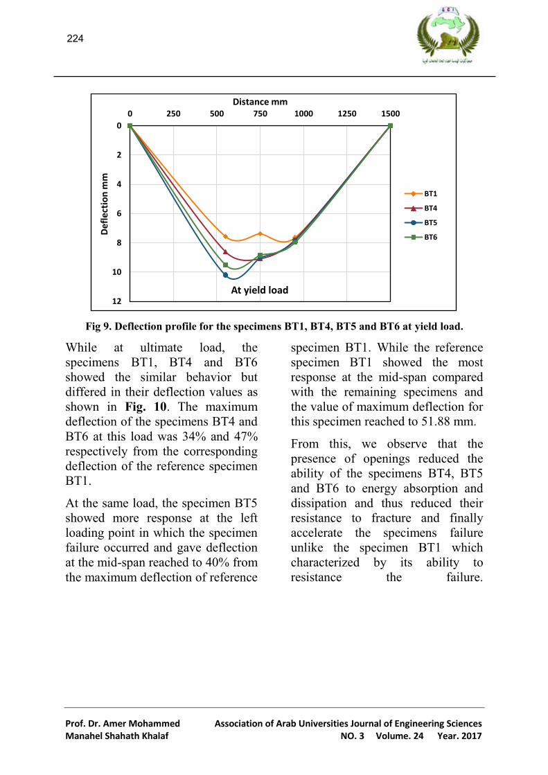
3.4 Deflection profile
Figs. 9 and 10. give a comparison of
deflection profile for the specimens
BT1, BT4, BT5 and BT6 at the yield
and ultimate load.
From Fig. 9 we note that at yield
load, the specimens BT5 and BT6
showed the similar behavior through
specimen loading processes. The
maximum deflection of these
specimens was at the left loading
point and equaled to 10.20 and 9.51
mm respectively. While the
maximum deflection of the specimen
BT4 was at the specimen mid-span
and reached 9.07 mm and it nearly
equaled the mid-span deflection for
the specimens BT5 and BT6.
0
10
20
30
40
50
60
BT1 BT4 BT5 BT6
Yield load kN 45 40 41 40
Ultimate load kN 54.8 45 44 47
Yield deflection Δy (mm) 7.38 9.07 9.03 8.85
Ultimate deflection Δu (mm) 51.88 17.57 20.48 24.35
Ductility Δu/Δy 7.03 1.94 2.27 2.75
Stiffness kN/mm 8.21 4.94 6.55 4.77
662
Prof. Dr. Amer Mohammed Association of Arab Universities Journal of Engineering Sciences Manahel Shahath Khalaf NO. 3 Volume. 24 Year. 2017
Fig 9. Deflection profile for the specimens BT1, BT4, BT5 and BT6 at yield load.
While at ultimate load, the
specimens BT1, BT4 and BT6
showed the similar behavior but
differed in their deflection values as
shown in Fig. 10. The maximum
deflection of the specimens BT4 and
BT6 at this load was 34% and 47%
respectively from the corresponding
deflection of the reference specimen
BT1.
At the same load, the specimen BT5
showed more response at the left
loading point in which the specimen
failure occurred and gave deflection
at the mid-span reached to 40% from
the maximum deflection of reference
specimen BT1. While the reference
specimen BT1 showed the most
response at the mid-span compared
with the remaining specimens and
the value of maximum deflection for
this specimen reached to 51.88 mm.
From this, we observe that the
presence of openings reduced the
ability of the specimens BT4, BT5
and BT6 to energy absorption and
dissipation and thus reduced their
resistance to fracture and finally
accelerate the specimens failure
unlike the specimen BT1 which
characterized by its ability to
resistance the failure.
0
2
4
6
8
10
12
0 250 500 750 1000 1250 1500D
efl
ecti
on
mm
Distance mm
At yield load
BT1
BT4
BT5
BT6

662
Prof. Dr. Amer Mohammed Association of Arab Universities Journal of Engineering Sciences Manahel Shahath Khalaf NO. 3 Volume. 24 Year. 2017
Fig 10. Deflection profile for the specimens BT1, BT4, BT5 and BT6 at ultimate load.
4. Summary and conclusion
This paper has displayed the results
of the experimental study on the
steel circular hollow specimens with
openings under bending moment. A
total of four specimens were tested
with diameter, thickness and length
equaled to 101.6, 3 and 1500 mm
respectively in order to examine the
influence of the presence of
openings on the structural behavior
and the bending properties of these
specimens. Based on the analysis of
the experimental data, the
conclusion as the following:
1. The presence of openings
reduces the ultimate strength
capacity as a result of the low
strain hardening capacity for
the specimen.
2. The presence of openings
decreases the specimen
ductility significantly because
of the low deflection at the
ultimate load. This little
ductility causes the sudden
and rapid drop in the
specimen loads carrying
capacity when access to the
ultimate load.
3. The presence of openings
reduces the specimen stiffness
as a result of the large
deformation that occurs at the
openings.
4. The presence of openings
reduces the specimen ability
to absorb and dissipate energy
and accelerates its failure.
5. Change the number of
openings at the pure bending
region doesn’t effect on the
structural behavior and the
yield and ultimate load values
because only one opening is
0
10
20
30
40
50
60
0 250 500 750 1000 1250 1500D
efl
ecti
on
mm
Distance mm
At ultimate load
BT1
BT4
BT5
BT6

662
Prof. Dr. Amer Mohammed Association of Arab Universities Journal of Engineering Sciences Manahel Shahath Khalaf NO. 3 Volume. 24 Year. 2017
reaching the ultimate load and controlling the specimen.
References
[1] Agarwal, D. S., and
Chhatwani, A. C. (2015). The
economic and structural analysis
of hollow structural sections.
International Journal on Recent
and Innovation Trends in
Computing and Communication,
3(2): 57-62.
[2] Chavan, V. B., Nimbalkar, V.
N., and Jasiwal, A. P. (2014).
Economic evaluation of open and
hollow structural sections in
industrial trusses. International
Journal of Innovative Research in
Science, Engineering and
Technology, 3(2): 9554-9565.
[3] Hoshikuma, J. I., and
Priestley, M. J. N. (2000).
Flexural behavior of circular
hollow columns with a single
layer of reinforcement under
seismic loading. SSRP, 13.
[4] Lawson, R. M. (1987).
Design for openings in the webs
of composite beams, CIRIA
special publication 51, SCI
publication 068. The Steel
Construction.
[5] Redwood, R. and Cho, S. H.
(1993). Design of steel and
composite beams with web
openings. Journal of Construction
Steel Research, 24: 23-41.
[6] Wardenier, J., Packer, J. A.,
Zhao, X. L., and Van der vegte,
G. J. (2002). Hollow sections in
structural applications.
Rotterdam, The Netherlands:
Bouwen met staal.
الدائرية المجوفة بوجود الفتحاتسموك الانثناء لمقاطع الحديد
مناهن شحاذ خمف
كمية الهندسة/ جامعة ديالى
أ. د. عامر محمد ابراهيم
كمية الهندسة/جامعة ديالى
الخلاصةوقاطع الحديد الدازي المجىف استخدوت بشكن واسع في العديد و التطبقات الهدس كأعضا كم. الأبحاخ المختبري حىه
المقاطع الدازي المجىف عدوا تتعزض لعز الاجا كات قمم. ذا البحح يقد دراس حىه سمىك الاجا لمقاطع الحديد الدازي
وخصاص الاجا ه سمشم و فحىصات الاجا و ادن دراس وفحص تأثير ودىد الفتحات عم الشمىك الهكم المجىف و خلا
ومي( عم التىال. العات ..10, 3, 1.101لهذه المقاطع. البراوج العىم تضى فحص اربع عات بقطز وسمك وطىه يشاو )
ا باسكاه. تاج العىن المختبر اضزت گو .30اسكاه واداد اقص يشاو ا بگو .09المفحىص تمتمك اداد خضىع يشاو
بالاضاف الى ا ودىد فتح ،أ ودىد الفتحات في العات قمن صلادتا ووطمتا بشكن كبير وأثز عم الاار الهكم لهذه العات
عم سع وقاووتا القصى. واحد او اثتين او ثلاخ في وطق التحىن الىسط لمع لم يؤثز


