Bending Beam With Single Reinforcement
33
BEND-Beam-SingleReinf BEND-Beam-SingleReinf 1 Assembled By : Kawan K. Ghafor Building Construction Department Sulaimany University
-
Upload
merankawan -
Category
Documents
-
view
25 -
download
0
description
Singly reinfored concrete beam
Transcript of Bending Beam With Single Reinforcement

BEND-Beam-SingleReinfBEND-Beam-SingleReinf 11
Assembled By : Kawan K. GhaforBuilding Construction Department
Sulaimany University

BEND-Beam-SingleReinfBEND-Beam-SingleReinf 22
UNITS
BENDING IN BEAM
ASSUMPTIONS
STRESS-STRAIN RELATIONSHIP
FAILURE MECHANISM
STRESS DIAGRAM
MAXIMUM & MINIMUM REINFORCEMENT
SECTION PROPERTIES
TABLES
EXERCISES

BEND-Beam-SingleReinfBEND-Beam-SingleReinf 33
UNITS :
LENGTH Span : m (meter) Element dimension : mm (millimeter)
FORCE, LOAD N (Newton) ; kN (kilo-Newton) 1 kg = 1 x 9.81 = 9.81 N 1 ton = 103 x 9.81 = 9.81 x 10³ N = 9.81 kN
STRESSMPa (1 MPa = 1 N/mm2)
DENSITYkN/m3

BEND-Beam-SingleReinfBEND-Beam-SingleReinf 44
BENDING IN BEAM
Crack in tension area
Reinforcement in tension area
M+
M+

BEND-Beam-SingleReinfBEND-Beam-SingleReinf 55
1
234
5
section strain
1
2
3
4
5
1
2
3
4
5

BEND-Beam-SingleReinfBEND-Beam-SingleReinf 66
1. Hypothesis of BernouilliIn bending plane sections remain plane.
2. Law of NavierThe longitudinal strains of fibers are proportional totheir distance to the neutral axis
ASSUMPTIONS
h
b
d
c
’ c
s
NeutralAxis
Where :c = concrete strains = steel strain
’c c
s d - c=
M+

BEND-Beam-SingleReinfBEND-Beam-SingleReinf 77
6. The tensile forces are carried entirely by the reinforcement in all sections. The role of concretein tension is neglected.
h
b
d
c’cu
s
NeutralAxis
M+
BEND-Beam-SingleReinfBEND-Beam-SingleReinf 88
y
1E
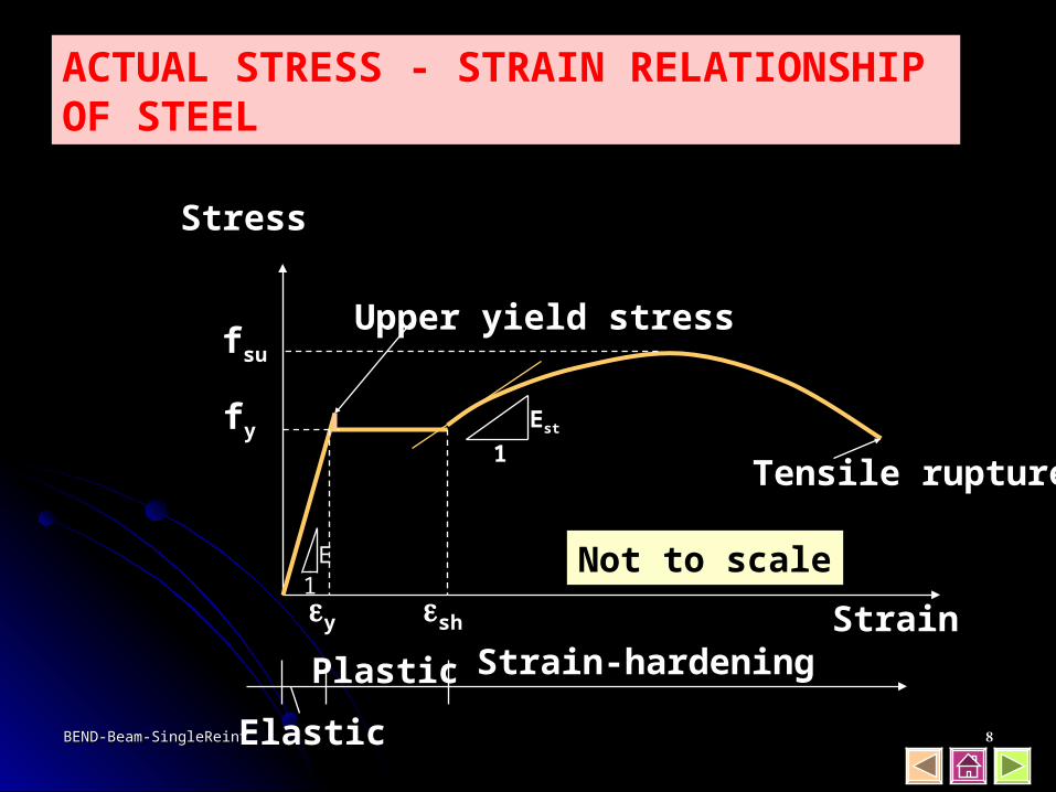
ACTUAL STRESS - STRAIN RELATIONSHIP OF STEEL
Stress
fsu
fy
sh Strain
Not to scale
Elastic
Plastic Strain-hardening
Tensile rupture
Upper yield stress
Est
1

BEND-Beam-SingleReinfBEND-Beam-SingleReinf 99
fs (MPa)
s
400
240
fy2 = 400 MPa
fy1 = 240 MPa
Where :fs = stress of steel ; fy = yield stresss = strain of steel ; y = yield strainEs = Modulus of elasticity = 200.000 MPa
For : s < y fs = Es . s
s y fs fy
IDEALIZED STRESS - STRAIN RELATIONSHIP OF STEEL
y1 y2
Es =fs
s

BEND-Beam-SingleReinfBEND-Beam-SingleReinf 1010
Where:fc’ = compression stress of concrete (based on cylinder specimen)fct = tension stress of concrete 0.5 fc’ (MPa)Ec = Modulus of elasticity of concrete 4700 fc’ (MPa)cu = Ultimate compression strain of concrete
ACTUAL STRESS - STRAIN RELATIONSHIP OF CONCRETE
fc’
Stress(MPa)
Strain ’cu
(0.003)fct

BEND-Beam-SingleReinfBEND-Beam-SingleReinf 1111
ACTUAL STRESS - STRAIN RELATIONSHIPOF SEVERAL CONCRETE STRENGTH
0.001 0.002 0.003 0.004
700
600
500
400
300
200
100 10
20
30
40
50
60
800
70
80
0
Strain, in/in (mm/mm)
kgf/c
m2
MPa
Co
mp
ress
ion
str
eng
th o
f co
ncr
ete,
fc’
, ks
i12
10
9
8
7
6
5
4
3
2
1
0
11
fc’ = 82.7 MPa
68.9
55.1
41.3
34.4
27.6
20.7

BEND-Beam-SingleReinfBEND-Beam-SingleReinf 1212
Shaded areaArea of rectangle1 =
1 = 0.5 = 0.333b. Triangle
1 = 0.67= 0.375
c. Parabola
cC
1 = 0.85= 0.425
f’c
a. Hyperbolic
T
c
0 4 8 12
Concrete strength (ksi)
0.2
0.4
0.6
0.8
1.0
0.0
1
•
•••• •
••• • •• •••
•••••• •• •
• • •• •
••
•• •• •• •
•
•
• ••• •
1 = 0.85
1 = 0.65
Values of 1
for = 0.85
COMPRESSION AREA OF BEAM IN BENDING
M+

BEND-Beam-SingleReinfBEND-Beam-SingleReinf 1313
C
T
½ a
Neutral axis
a = 1cc
0.85 fc’
RECTANGLE SCHEME OF STRESS DIAGRAM
H = 0 C = T M = 0 Mn = C . (d - ½ a)
Mn+
b
d
BEND-Beam-SingleReinfBEND-Beam-SingleReinf 1414
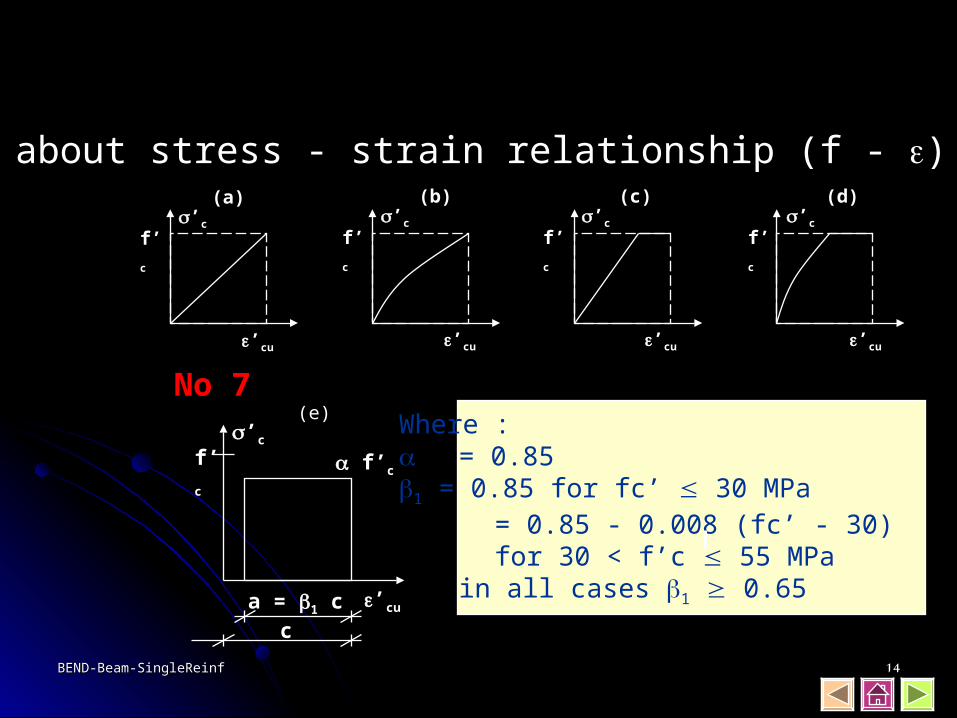
No (6) about stress - strain relationship (f - ) of concrete(a)
’c
f’c
’cu
(b)’c
f’c
’cu
(c)’c
f’c
’cu
(d)’c
f’c
’cu
No 7(e)
’c
f’c f’c
’cua = 1 cc
Where : = 0.851 = 0.85 for fc’ 30 MPa = 0.85 - 0.008 (fc’ - 30)
for 30 < f’c 55 MPain all cases 1 0.65
BEND-Beam-SingleReinfBEND-Beam-SingleReinf 1515
y
y
yC
C
C
yC
0.85 fc’
fc’
fc’
fc’
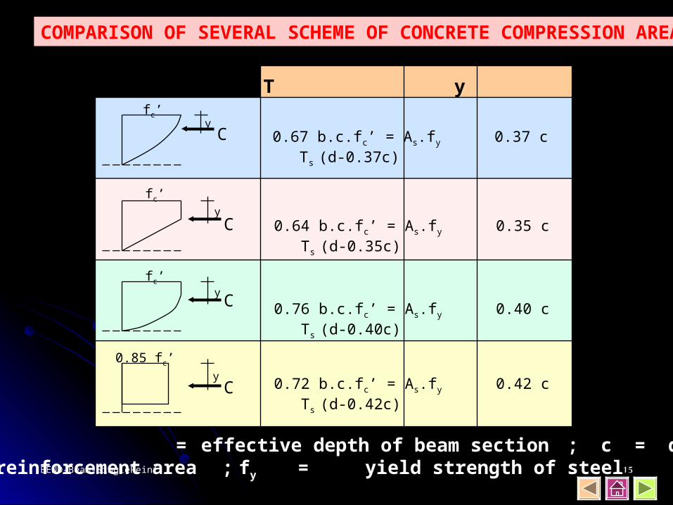
0.67 b.c.fc’ = As.fy 0.37 c Ts (d-0.37c)
0.64 b.c.fc’ = As.fy 0.35 c Ts (d-0.35c)
0.76 b.c.fc’ = As.fy 0.40 c Ts (d-0.40c)
0.72 b.c.fc’ = As.fy 0.42 c Ts (d-0.42c)
C = T y Mu
Note : d = effective depth of beam section ; c = depth of neutral axisAs = steel reinforcement area ; fy = yield strength of steel
COMPARISON OF SEVERAL SCHEME OF CONCRETE COMPRESSION AREA

BEND-Beam-SingleReinfBEND-Beam-SingleReinf 1616
Mean 241.2 55.1 22.0 79.3
y
y
yC
C
C
yC
0.85 fc’
fc’
fc’
fc’
241.2 57.6 21.3 79.3
C = T (kN) c (mm) y (mm) Mu (kNm)
241.2 60.3 21.1 79.3
241.2 50.8 20.3 79.5
241.2 53.6 22.5 79.0
The result difference is less than 1%
250
350
As
fc’ = 25 MPa fy = 400 MPaAs = 3D16 = 603 mm2
b = 250 mm h = 350 mm
EXAMPLE

BEND-Beam-SingleReinfBEND-Beam-SingleReinf 1717
FAILURE MECHANISM DUE TO BENDING
BALANCED FAILURE
UNDER-REINFORCED FAILURE /TENSION STEEL YIELDING
OVER-REINFORCED FAILURE/CONCRETE COMPRESSION FAILURE

BEND-Beam-SingleReinfBEND-Beam-SingleReinf 1818
s = y s > y s < y
FAILURE MECHANISM
cbalc
c
’cu= 0.003
Balanced Under- Over- Failure Reinforced Reinforced
As = As bal As < As bal As > As bal
MU+
’cu= 0.003 ’cu= 0.003

BEND-Beam-SingleReinfBEND-Beam-SingleReinf 1919
600600 + fy
cbal = d ……… (1)
1. BALANCED FAILURE ’cu = 0.003 is reached at the same time when s = y
As bal
b
d
’cu = 0.003
cbal
s = y
C
T
d-½a
Strain Stress
abal
0.85 fc’
fs = fy
cbal 0.003 d 0.003 + y
=Multiplied with Es = 2.105 MPa
MU+

BEND-Beam-SingleReinfBEND-Beam-SingleReinf 2020
C = T
0.85 fc’ . abal . b = As bal . fy
0.85 fc’ . 1 . cbal . b = As bal . fy
0.85 fc’ . 1 . cbal . b fy
0.85 fc’ . 1 . cbal
fy . d
As bal =
bal = … (2)
: bd
0.85 fc’ . 1 600 fy 600 + fy
bal = .
Substitute eq. (1) into eq. (2) found :

BEND-Beam-SingleReinfBEND-Beam-SingleReinf 2121
2. UNDER-REINFORCED FAILURE ’cu = 0.003 is reached when s >> y ; < bal ; c < cbal
H = 0 C = T 0.85 fc’ . a . b = As . fy
As . fy
0.85 fc’ .a.b
Mn = T (d - ½ a)= As . fy …(2)
a = …. (1)
fs = fys >> y
As
b
d
’cu = 0.003
cC
T
d-½a
Strain Stress
a0.85 fc’
MU+

BEND-Beam-SingleReinfBEND-Beam-SingleReinf 2222
Mn bd2
Mn = As . fy ( d - )½ . As . fy
0.85 fc’ . b
: bd2
= . fy ( 1 - 0.59 ) fy
fc’
bd2 . fy ( 1 - 0.59 )
fy
fc’Mn =
Substitute eq. (1) into eq.(2) found :

BEND-Beam-SingleReinfBEND-Beam-SingleReinf 2323
s < y fs < fy
3. OVER-REINFORCED FAILURE ’cu = 0.003 is reached when s < y ; > bal ; c > cbal
As
b
d
’cu = 0.003
cC
T
d-½a
Strain Stress
a
0.85 fc’
This failure mechanism should be avoided. Concrete failure prior to the yielding of steel could lead to a brittle failure condition.
MU+

BEND-Beam-SingleReinfBEND-Beam-SingleReinf 2424
MAXIMUM REINFORCEMENT (max)
max = 0.75 bal
Where : bal = reinforcement ratio in balanced strain condition
This specification is made in order to ensure that only Under-Reinforced Failure occur in the section.
As bal
b
d
’cu = 0.003
c
y
Strain
’cu + y
c
y
MU+bal =
As bal
b . d

BEND-Beam-SingleReinfBEND-Beam-SingleReinf 2525
MINIMUM REINFORCEMENT (min)
1.4 fy
min =
This specification is made in order to anticipate a significant raise in steel stress (fs )when the concrete is starting to crack. Significant raise of steel stress make the steel cut off suddenly. NOTE : For slab : min = 0.002 ; fy = 240 MPa
= 0.018 ; fy = 400 MPato anticipate creep and shrinkage in concrete

BEND-Beam-SingleReinfBEND-Beam-SingleReinf 2626
RECTANGULAR SECTION OF REINFORCED CONCRETE
Compression Reinforcement
Stirrup
Concrete cover
Additional reinforcement(Torsion reinf. : 12mm)
Tension reinforcement
Concrete cover
db or 25 mm
300 mm
MU+

BEND-Beam-SingleReinfBEND-Beam-SingleReinf 2727
TABLE 5.1.a - CUR IV
Mu/bd2 fy = 240 MPa fy = 400 MPa c/d z/d au au
100 0,0005 0,191 0,0003 0,318 0,012 0,995200 0,0011 0,190 0,0006 0,317 0,023 0,990300 0,0016 0,189 0,0010 0,315 0,035 0,985400 0,0021 0,188 0,0013 0,314 0,047 0,980500 0,0027 0,187 0,0016 0,312 0,059 0,975600 0,0032 0,186 0,0019 0,310 0,071 0,970700 0,0038 0,185 0,0023 0,309 0,084 0,964800 0,0043 0,184 0,0026 0,307 0,096 0,959900 0,0049 0,183 0,0029 0,305 0,109 0,9541000 0,0055 0,182 0,0033 0,303 0,122 0,9481100 0,0061 0,181 0,0036 0,302 0,135 0,9431200 0,0067 0,180 0,0040 0,300 0,148 0,9371300 0,0073 0,179 0,0044 0,298 0,161 0,9321400 0,0079 0,178 0,0047 0,296 0,174 0,926….. ……. ……. …… …… …… …...3000 0,0190 0,158 0,01114 0,263 0,422 0,8213100 0,0199 0,156 0,0119 0,260 0,440 0,8133200 0,0207 0,155 0,0124 0,258 0,458 0,8053300 0,0216 0,153 0,478 0,7973400 0,0225 0,151 0,497 0,7893500 0,0234 0,150 0,518 0,780
CONCRETE STRENGTH f’c 15 = 0,8

BEND-Beam-SingleReinfBEND-Beam-SingleReinf 2828
MINIMUM CONCRETE COVER (mm)
Structural Un-Exposed to Exposed toComponent ground or weather ground or weather
Floor / wall ØD36 : 20 ØD16 : 40> ØD36 : 40 > ØD16 : 50
Beam all diameter : 40 ØD16 : 40 > ØD16 : 50
Column all diameter : 40 ØD16 : 40 > ØD16 : 50
For all cast in situ concrete which directly contact with ground,minimum concrete cover : 70 mm

BEND-Beam-SingleReinfBEND-Beam-SingleReinf 2929
AREA OF REINFORCEMENT (mm2)
Number of barØ 1 2 3 4 5 6 7 8 9 10
6 28 57 85 113 141 170 198 226 254 2838 50 101 151 201 251 302 352 402 453 50310 79 157 236 314 393 471 550 628 707 78512 113 226 339 452 565 679 792 905 1018 113114 154 308 462 616 770 924 1078 1232 1385 153916 201 402 603 804 1005 1206 1407 1608 1810 201119 284 567 851 1134 1418 1701 1985 2268 2552 283520 314 628 942 1257 1571 1885 2199 2513 2827 314222 380 760 1140 1521 1901 2281 2661 3041 3421 380125 491 982 1473 1963 2454 2945 3436 3927 4418 490928 616 1232 1847 2463 3079 3695 4310 4926 5542 615832 804 1608 2413 3217 4021 4825 5630 6434 7238 8042

BEND-Beam-SingleReinfBEND-Beam-SingleReinf 3030
EXERCISE - 1 Analysis of rectangular section due to bending
A rectangular section of reinforced concrete as drawn below :
fc’ = 20 MPafy = 400 MPab = 300 mmh = 500 mm
a. Check the failure mechanism of this section, UNDER or OVER-REINFORCED FAILURE ?
b. Based on (a), find the depth of neutral axis, c, and ultimate moment, Mu that could be resisted by this section.
c. If the reinforcement 4 16 is replaced with reinforcement 6 19,
how much Mu would be increased ?
b
h416MU+

BEND-Beam-SingleReinfBEND-Beam-SingleReinf 3131
A beam of reinforced concrete resists the uniformed dead load (qD) and live load (qL) as drawn below :
Sectional dimension : 400 x 600 mm, concrete strength fc’ = 25 MPaand steel strength fy = 400 MPa.a. Due to the loads, draw the moment diagram of the beam. b. Design the reinforcement of beam at maximum M+ (in the middle
of span AB) and maximum M- (at support B). c. Check the chosen reinforcement to maximum and minimum
reinforcement requirements as specified in SNI.
qL = 20 kN/mqD = 15 kN/m
A B C7.20 3.60
EXERCISE - 2 Design of rectangular section due to bending

BEND-Beam-SingleReinfBEND-Beam-SingleReinf 3232
A rectangular section of reinforced concrete as drawn below :
3 22
b
h
a. If fc’ = 20 MPa, fy = 400 MPa, find the ultimate moment Mu that could be resisted by this several value of dimension :b = 300 mmh = 300, 400, 500, 600 mmDrawn your results as graphical model. Mu
(kNm)
h (mm)
b. Compare the result of (a), with another relationship :h=400 mm and b = 300, 400, 500, 600 mm
c. To resist Mu = 400 kNm with beam width b=400 mm,how much hmin ?
EXERCISE - 3 Analysis of rectangular section due to bending

BEND-Beam-SingleReinfBEND-Beam-SingleReinf 3333
A trapezoid section of reinforced concrete as drawn below :
500
400
600
8 19
fc’ = 25 MPafy = 400 MPa
How much Mu that could be resisted by this section ?
EXERCISE - 4 Analysis of trapezoid section due to bending
End of presentation