Bendigo Regional Institute of TAFE -...
40
Bendigo Regional Institute of TAFE NES504CA Computer/Electronic Industry Preparation Technology Research Project Semester 2 - 2004 The Technological Pathway to the modern HF Amateur Radio Transceiver. Teacher: Ian Grinter Compiled by Kevin Crockett (VK3CKC)
Transcript of Bendigo Regional Institute of TAFE -...
Bendigo Regional Institute of TAFE
NES504CA Computer/Electronic Industry Preparation
Technology Research ProjectSemester 2 - 2004
The Technological Pathway to the modern HF Amateur RadioTransceiver.
Teacher: Ian Grinter
Compiled by Kevin Crockett (VK3CKC)

BENDIGO REGIONAL INSTITUTE OF TAFEAdvanced Diploma of Electronics
Executive Summary
It is a little over 100 years since certain technological discoveries made it possible for individuals topursue hobby interests in radio communications. The period commenced with an unregulatedactivity, the necessity of building one’s own rudimentary equipment, self experimentation anddevelopment through to rigid licensing and controls, commercial manufacture and competition forspectrum space.
The majority of amateur equipment was once home made. This is no longer the case. Theavailability of specialised components is diminishing. Computer-aided manufacturing has resultedin parts that you can hardly see, let alone hand solder onto a circuit board. Commerciallymanufactured equipment is far smaller, probably more reliable, and certainly has far more operatingconveniences than one could ever hope to emulate at home – if you could find a suitable design andthen source the components. You will not be able to construct a full-fledged transceiver withanything like the performance, convenience and size of commercial equipment.
There is still scope for home construction of ancillary support and test equipment.
Anything is available, at a price and it is becoming more and more necessary to ensure that onereceives value for money. If you are on a limited budget, like most of us, how should you go aboutmaking your spending choice? How much must you spend to ensure that your requirements will bemet?
Amateur activities fall into two basic categories. There are those that are very serious and look forthe utmost from their equipment and there are those that are far more casual and don’t have eitherthe time or the finances to extract the last degree of performance. It is a hobby after all.
The final choice comes down to which of the two categories cover your interests and then, yourbudget limitations.
If you are casual operator and your decision is not restricted by budget, purchase whatever you canafford and try to get the best-perceived value for the price.
If you are a serious contester, research the important specifications for your particular area ofinterest. An older transceiver may have superior performance for your budget. If your budget is nota limiting factor, be prepared to pay at least $AUD9,000.00 if you are going to purchase a modern,amateur band only transceiver.
Page 2 of 40
BENDIGO REGIONAL INSTITUTE OF TAFEAdvanced Diploma of Electronics
Table of Contents
Introduction..................................................................................................................... 4
Background – 600BC to 1910......................................................................................... 5
Methodology.....................................................................................................................9
Findings – Impacting Technologies 1913 to 2002....................................................... 10
Conclusion...................................................................................................................... 23
References.......................................................................................................................25
Acknowledgements........................................................................................................ 27
AppendicesAppendix 1 - The Wadley Loop Drift Cancelling System.........................................28Appendix 2 – ICOM IC-7800 Brochure Details........................................................29Appendix 3 - Yaesu Musen FT-847 Earth Station.................................................... 31Appendix 4 – Transceiver Specification Comparison............................................... 33Appendix 5 - Amateur Digital Communication Modes............................................ 35Appendix 6 – Digital Software Screenshots..............................................................38Appendix 7 - Websites of Interest............................................................................. 39
Page 3 of 40

BENDIGO REGIONAL INSTITUTE OF TAFEAdvanced Diploma of Electronics
Introduction
The advance of electronic and communication technologies has had a large impact on amateur radiooperators since the inception of their worldwide activity in the early 20th Century. Each time a newtechnology, or a significant advance on an existing one, occurs, the amateur is faced with a decision.This decision is to either embrace the technological advance and all its perceived benefits, or toignore or reject it. Eventually, those who have not taken the embracing step fall behind and find itincreasingly difficult to maintain their status quo by the inability to source replacement componentsfor their eventually outdated equipment.
The decision to embrace, or otherwise, is often influenced by, on the one hand, a reluctance toventure into the unknown and on the other, an opportunity to learn about and use something new.
Like all technologies and inventions, each has existed in its own space in time by the existence ofearlier inventions and technologies. The modern computer, as an example, could not exist withoutthe prior existence of the semi-conductor and digital technologies assisted by the myriad of priortechnological discoveries that made them possible.
The modern amateur transceiver with digital signal processing, digital memories, computer interfaceand surface mount components is a vast departure from the equipment used by early amateur radiopioneers who were inspired by the efforts of Marconi, Tesla, Edison, Faraday, de Forest and manyothers. Until recently amateurs were known for their resourcefulness and ability to repair their ownequipment. They were at the forefront of technology in many aspects. The situation has changed towhere technology is advancing at a rate where individual amateurs can no longer keep up with it atthe detailed level of the past. Except for those employed in the industry, their knowledge is on amore general level.
This report documents the impacting technologies that have evolved over the last century orso, culminating in the facilities and technology of the modern HF transceiver. It will end witha broad overview of whether modern state-of-the-art transceivers are really any better thantheir predecessors.
Page 4 of 40
BENDIGO REGIONAL INSTITUTE OF TAFEAdvanced Diploma of Electronics
Background
Amateur Radio was a hobby offshoot of radio communications that resulted from a number ofearlier inventions and discoveries.
There are many interesting publications and Internet web sites that contain historical accounts ofrelevant inventions and discoveries over many centuries of very little progress. The last century hasturned this right around. Technological advances today are occurring at an astounding rate.
To set the stage for amateur radio and the modern HF transceiver, it is necessary to start somewhereand perhaps, other than starting with the creation of the universe, we should start with a discoverythat would eventually play a much more important role than the curiosity it attracted at the time.
600BC The discovery of the ability of amber to produce static electricity and attract thin objectslike feathers, leaves or fibres after being rubbed with wool or fur. The famous Greekphilosopher Thales of Miletus called this special property "elektron" from which is derivedthe Latin word "electrocus" meaning "produce from amber by friction" and of course themodern word "electricity". (Lombry, Page 1)
1752 Benjamin Franklin flew a kite at Philadelphia during a thunderstorm to observe sparkingfrom the kite’s wire. (WIA:15).
1782 Count A. Volta began developing the first “Voltaic” battery. (WIA:15).
1789 Dr. Von Sommering applied electrical current as a means of signaling. (WIA:15).
1819 H.C. Oersted and A.M Ampere conducted experiments with electro-magnetism. (WIA:15).
1820 Oersted established the connection between electric current flow and magnetic field.Parallel work by Ampere. (WIA:15).
1826 G.S. Ohm formulated Ohms Law. (WIA:15).
1831 Michael Faraday discovered electro-magnetic induction. Parallel work was done by J.Henry who also continued work on inductance. (WIA:15).
1832 Samuel Morse developed a system of ‘Morse’ code. K.F. Gauss and Professor Webersucceeded in developing two-wire electric telegraph. (WIA:15).
1835 Munk experimented with electro-magnetism. (WIA:15).
1837 ‘Morse’ code was patented. Wheatstone and Cooke patent a system of electrical telegraphy.(WIA:15).
1838 Morse code telegraphy transmitted over a 10 mile path of wire. C.A. Steinheildemonstrated first successful single-wire telegraph (earth return). (WIA:15).
1840 Morse introduced code and patented the ‘key’ to transmit and receive wire telegraphy.Joseph Henry first produced high frequency oscillations. (WIA:16).
1842 Henry magnetised needles from a distance of 200 feet. (WIA:16).
1855 D.E. Hughes patented a type printing telegraph machine. (WIA:16).
1864 J.C. Maxwell mathematically proved the existence of radio waves. (WIA:16).
1865 The International Telegraph Union (ITU) was founded in Paris by 20 nations. (WIA:16).
1866 C and S.A. Varley made observations on the conductivity of metallic powders. (WIA:16).
Page 5 of 40
BENDIGO REGIONAL INSTITUTE OF TAFEAdvanced Diploma of Electronics
1867 Ruhmkorff perfected his induction coil. (WIA:16).
1868 Mahlon Loomis demonstrated wireless ‘communication’ showing that a kite sent aloftaffected the flow of current in another kite connected to a galvanometer located 29 kmaway from the first kite. This discovery triggered the development of wireless telegraphyfor long distance communications.
Loomis is also credited with:
The first formulation of the idea that ‘waves’ travel out from an antennaThe first use of a complete antenna and ground systemThe first experimental transmission of wireless telegraph signalsThe first use of balloons and kites to raise an antenna wireThe first vertical antenna (a wood tower supporting a steel rod)The first patent for wireless telegraphy. (Lombry, Page 2)
Loomis had difficulty in getting backing for a lot of his research and development. An unnamedauthor (The Australasian Radio World, 1948, p11) provides ‘an interesting tale of coincidences andcircumstances’.
But this kindly man was without adequate funds to develop fully the secret revealed to him by Nature.Loomis sought to interest people in his invention to acquire financial support. But imagine trying to convincepeople then that air could be a carrier for electrical impulses when such persons had been only recentlyconverted, with difficulty, to the wired telegraph! People were incredulous and the inventor became the buttof ridicule and coarse humour.
The sceptics had to be convinced. The patient, tireless dentist managed to scrape together enough money toconduct an experiment. In 1868 (or 1866) Loomis, in the presence of scientists and others, communicatedbetween two mountain spurs in the Blue Ridges of West Virginia, eighteen miles apart. The operators of eachparty were provided with telescopes so that each could sight the others’ station. Loomis produced electricaldischarges when he touched hi kite wire to the ground, but had no means of detecting them except for thegalvanometer at the far point that deflected to indicate a passage of current. He had sent out true waves and itwas the first time that such signals had been transmitted over a distance without wires.
1873 J. May observed that sunlight shining on to selenium resistors varied the current flow in acircuit. (WIA:16).
1874 Alexander Graham Bell and T.A. Watson commenced experiments to transmit soundselectrically – succeeded in transmitting speech in 1875. (WIA:16).
1875 Edison claimed the discovery of “etheric force”. (WIA:16).
1867 Ruhmkorff perfected his induction coil. (WIA:16).
1877 Edison invented the carbon microphone and the phonograph. (WIA:16).
1878 D.E. Hughes invented the microphonic detector. (WIA:16).
1879 Hughes demonstrated it was possible to transmit signals through space over severalhundred yards. (WIA:17).
1883 Edison discovered the electron emission of a conductor filament heated at high temperaturein a vacuum. This invention will later be at the root of the function of the electronic valveor tube. (Lombry, Page 2)
1888 Heinrich Hertz demonstrated electromagnetic waves across a room (thought to be about450MHz) by conduction and a resonator – radiation as opposed to induction. (WIA:17).
Page 6 of 40
BENDIGO REGIONAL INSTITUTE OF TAFEAdvanced Diploma of Electronics
1890 Professor Branley conducted observations on conductivity for emf and produced a kind ofcoherer (name given in 1984). (WIA:17).
1895 Marconi transmitted Morse over a 1.5 mile radius with his ‘Cymoscope’. (WIA:17).
1897 Marconi demonstrated wireless over an 8 mile path on Salisbury Plain, U.K. and over a 12mile path between 2 Italian warships. (WIA:17).
1898 Marconi made improvements to coherer reception using an air-cored transformer he calleda “jigger”. (WIA:18).
Meade Dennis, successfully repeated Marconi’s experiments and installed what is regardedas the first amateur experimental radio station at Woolwich Arsenal. (Lombry, Page 3).
Leslie Miller published the first description of what he called a simple-to-build transmitterand receiver for an amateur audience in The Model Engineer and Amateur Electrician.(Lombry, Page 3).
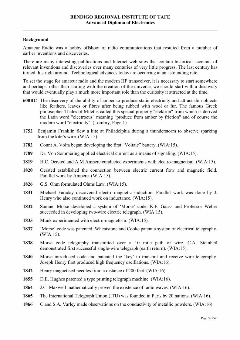
The simplest spark gap transmitter using a 25 cm (10")coil. The battery and the key are applied onbrass contacts at right of the plate. The tuningcoil and antenna are connected on top of theright electrode. The system is grounded viathe left electrode. (Lombry, Page 3).
1899 US magazine Scientific American published a long article discussing Marconi's results andthe July 1899 issue of American Electrician magazine gave details on the construction ofMarconi's antenna and his wireless radio equipment. (Lombry, Page 3).
1901 Marconi’s historic reception of a spark transmission of the letter “S” from Poldhu,Cornwall, England to St. John's, Newfoundland - a distance of 3360 km. Thisdemonstration launched the commercial use of radio. (Lombry, Page 3).
1902 Marconi designed and patented the magnetic detector. (WIA:19).
1903 Fessenden recognized that continuous wave transmission was required for speech andcontinued the work of Nikola Tesla, John Stone, and Elihu Thomson. Fessenden felt hecould also transmit and receive Morse code better by the continuous wave method thanwith a spark-apparatus as Marconi was using and started experimenting with highfrequency alternators. (NMAH Archives Centre).
1904 Fleming developed the first vacuum diode using a cathode and an anode, known as theFleming Valve and four years later he invented the tungsten filament. Two years later, Leede Forest took Fleming's valve, added a third element, called the grid, and named the result(a triode), the Audion. It could amplify a signal 5 times. Its use by amateurs did not occuruntil 1912, following a discovery by Edwin H. Armstrong of the effects of applyingfeedback. (Lombry, Page 3).
1905 A "state of the art" spark gap transmitter operated on 400 metres (750 kHz) and generated asignal from about 250 metres (1.2 MHz) to 550 metres (545 KHz). The receiver consistedof simple unamplified detectors, generally coherers (small quantity of metal filings lying
Page 7 of 40

BENDIGO REGIONAL INSTITUTE OF TAFEAdvanced Diploma of Electronics
loosely between metallic electrodes). This later gave way to the famous and more sensitivegalena crystal sets. Tuners were primitive or nonexistent. Although these wireless stationswere terribly inefficient compared to modern standards, their transmitters were able toreach distances from as little as 180 m with a 12 mm coil to about 160 km using a 38 cmspark coil and a kilowatt station. Professional installations like ships at sea usedtransmitters up to 5 kW and reached distances up to 800 km, a record for the time.(Lombry, Page 3).
1906 Professors Pierce and Pickard investigated properties of quartz and Rochelle salt crystaldetectors. (WIA:20).
General Dunwoody announced success of crystal detectors for radio waves. (WIA:20).
1908 The magazine Modern Electrics was the first magazine fully dedicated to wirelesscommunication. Its circulation passed from 2000 to over 30,000 copies in just two years.At about the same time the first experimenters found the first radio handbook titled"Wireless Telegraph Construction for Amateurs" on bookstore shelves. (Lombry, Page 3).
1909 G.A. Taylor demonstrated that pictures could be sent by wireless (done successfully in1910). (WIA:21).
1910 Formation of the first amateur organization – the Junior Wireless Club Ltd. Of New York(later became Radio Club of America). (WIA:21).
Amateur Radio had now been born and its popularity began to soar as many ordinary citizens andother enthusiasts, inventors and scientists began experimenting with radio communications. Theearly transmitters were spark generators with coherer detectors for receiving. The transceiver andmodulation methods had not yet been invented.
The 20th Century settled in. Over the next 100 years, the developmental pace of new technology,fuelled by mass production, commercial interests and consumer entertainment goods, would see amultitude of inventions and discoveries that would take radio communications in directions thatmay never have been imagined by those early pioneers who paved the way for it.
Page 8 of 40
BENDIGO REGIONAL INSTITUTE OF TAFEAdvanced Diploma of Electronics
Methodology
Research for this report will cover personal experience, amateur radio publications, electronicsjournals, manufacturer’s brochures, user manuals, advertisements and the Internet.
Page 9 of 40

BENDIGO REGIONAL INSTITUTE OF TAFEAdvanced Diploma of Electronics
FindingsIn 1912, the International Telegraph Union’s 2nd World Congress promulgated Radio TelegraphConvention Regulations. As a practical outcome, ‘experimenters’ (name changed to ‘amateurs’ afterthe Second World War) and other services listed, were restricted to ‘200 metres and down’(WIA:23). It was expected that these frequencies, 1.5MHz and higher, would be pretty safe and theamateurs would not be able to do a great deal with them.
The typical equipment for transmitting and receiving radio communications consisted of a sparktransmitter and coherer-based receiver. The transceiver, which permits the dual use of somemodules for transmitting and receiving and automatic transmit/receive switching, was not inventeduntil many years later.
John Gazard, (Gazard:14) sums up the amateur technology level of the day as he writes:In its simplest form, the spark transmitter consisted of a spark coil with its spark gap in series with the aerial andearth, and the receiver had a crystal detector and headphones in series with the aerial and earth. This simple formdepended on the length of the aerial to fix its frequency, but its signals covered a very wide band and had a rangemeasured in yards rather than miles.
An improved form of transmitter was used by most amateurs. It operated as follows. When the primary of thespark coil was interrupted, a current flowed in the secondary and the capacitor was charged up until the voltagewas sufficient to cause a discharge across the spark gap. This spark discharge caused a spurt of current which setoscillating currents flowing at the resonant frequency of the circuit. These currents died away (were damped) untilthe next spark arrived when they recommenced. The resulting waveform was known as a damped wave.
The spark transmitter was not efficient as regards output compared with input and its signals spread over a wideband. The crystal receiver was not sensitive and its selectivity was poor.
The inefficiency and frequency bandwidth of the spark transmitter and the insensitivity of the crystalreceiver had to wait for feedback and amplification developments in order to improve them.
America has always had the largest population of amateurs and it is no real surprise to find thatAmerica features so prominently in past and ongoing development of this technology.
Impacting Technologies1913 Lee de Forest, Langmuir, Hogan and Meissner introduced principles of self-oscillation and
regenerative oscillation using the triode valve. (WIA:24).
Major Edwin H. Armstrong (also a US amateur) developed the regenerative circuit.(WIA:24).
Armstrong discovered that, when positive feedback was sufficiently increased, the circuitbecame an oscillator, and was able to transmit its own signal. Thus, in one master-stroke, asensitive “regenerative” receiver and an effective electronic transmitter had been born.(Columbia University).
1914 Amateur stations closed down for the First World War. (WIA:24).
Langmuir granted a patent for a “hard” valve (used in First World War developments forvoice-modulated radio waves. (WIA:24).
There were great improvements and developments during the war due to necessity.
1916 General Electric Co. developed a tetrode valve by inserting a fourth element. (WIA:24).
Page 10 of 40
BENDIGO REGIONAL INSTITUTE OF TAFEAdvanced Diploma of Electronics
By 1916, there were 5,000 licensed US amateur licenses, 1000 ARRL relay stations, and150,000 receivers in use. In the UK there were nearly 2,000 licences and ten times less oreven a handful in the other European countries. (Lombry, Page 5).
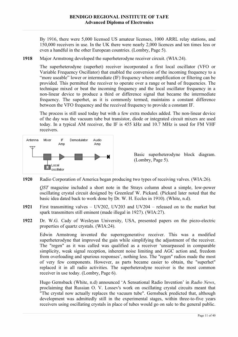
1918 Major Armstrong developed the superheterodyne receiver circuit. (WIA:24).
The superheterodyne (superhet) receiver incorporated a first local oscillator (VFO orVariable Frequency Oscillator) that enabled the conversion of the incoming frequency to a“more useable” lower or intermediate (IF) frequency where amplification or filtering can beprovided. This permitted the receiver to operate over a range or band of frequencies. Thetechnique mixed or beat the incoming frequency and the local oscillator frequency in anon-linear device to produce a third or difference signal that became the intermediatefrequency. The superhet, as it is commonly termed, maintains a constant differencebetween the VFO frequency and the received frequency to provide a constant IF.
The process is still used today but with a few extra modules added. The non-linear deviceof the day was the vacuum tube but transistor, diode or integrated circuit mixers are usedtoday. In a typical AM receiver, the IF is 455 kHz and 10.7 MHz is used for FM VHFreceivers.
Basic superheterodyne block diagram.(Lombry, Page 5).
1920 Radio Corporation of America began producing two types of receiving valves. (WIA:26).
QST magazine included a short note in the Strays column about a simple, low-poweroscillating crystal circuit designed by Greenleaf W. Pickard. (Pickard later noted that thebasic idea dated back to work done by Dr. W. H. Eccles in 1910). (White, n.d).
1921 First transmitting valves – UV202, UV203 and UV204 – released on to the market butspark transmitters still eminent (made illegal in 1927). (WIA:27).
1922 Dr. W.G. Cady of Wesleyan University, USA, presented papers on the piezo-electricproperties of quartz crystals. (WIA:24).
Edwin Armstrong invented the superregenerative receiver. This was a modifiedsuperheterodyne that improved the gain while simplifying the adjustment of the receiver.The "regen" as it was called was qualified as a receiver ‘unsurpassed in comparablesimplicity, weak signal reception, inherent noise limiting and AGC action and, freedomfrom overloading and spurious responses’, nothing less. The "regen" radios made the mostof very few components. However, as parts became easier to obtain, the "superhet"replaced it in all radio activities. The superheterodyne receiver is the most commonreceiver in use today. (Lombry, Page 6).
Hugo Gernsback (White, n.d) announced ‘A Sensational Radio Invention’ in Radio News,proclaiming that Russian O. V. Lossev's work on oscillating crystal circuits meant that"The crystal now actually replaces the vacuum tube". Gernsback predicted that, althoughdevelopment was admittedly still in the experimental stages, within three-to-five yearsreceivers using oscillating crystals in place of tubes would go on sale to the general public.
Page 11 of 40
BENDIGO REGIONAL INSTITUTE OF TAFEAdvanced Diploma of Electronics
However, it turned out that for the next few decades radio enthusiasts would have to makedo with incremental improvements in vacuum tube design -- tubes that required lesscurrent, lasted longer, and could run on household electrical current instead of storagebatteries. It was only when a deeper knowledge of solid state physics made it possible torefine oscillating crystals into much more practical and reliable "transfer resistors"(transistors) that, beginning in the mid-1950s, the lightweight radios running on flashlightbatteries envisioned by Gernsback finally became available to the general public. (White,n.d).
1926 Quartz crystals were first introduced in USA. By 1935, they had largely replaced self-excited oscillators. (Gazard, 1985:15).
This development enabled greater and more precise control of frequency. Non crystal-based oscillators tend to drift in frequency due to temperature changes.
1927 An International Radio Telegraph Conference, the ‘first since the value of the higherfrequencies were discovered’, fixed and considerably narrowed amateur frequency bands.(Gazard, 1985:15).
1933 During the 1930’s, the superhet was the most predominant circuit. The spark gaptransmitter had been banned due to its wide bandwidth requirement.
Princeton University commenced experiments with quantum theory and semiconductors.(Lombry, Page 7).
R/9 magazine published a three-part article entitled "Single Sideband Transmission forAmateur Radiophones" written by Robert M. Moore, W6DEI. It reported an experimentusing "single-side-band, suppressing carrier" mode, SSSC. However SSB (single sideband)as it will be called, had to wait until 1947. (Lombry, Page 7).
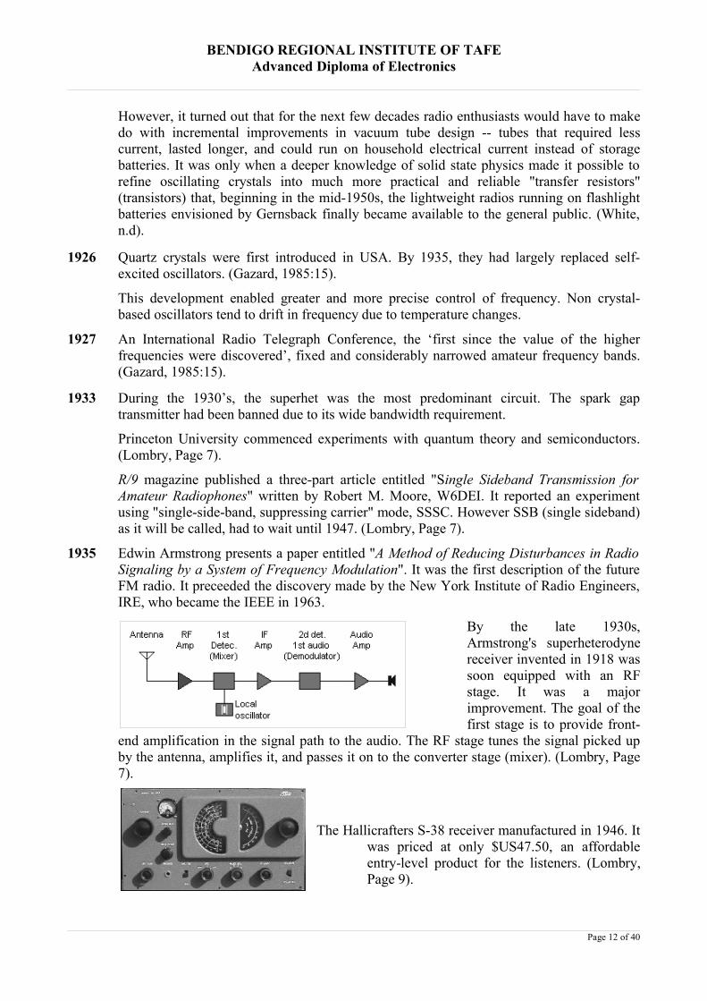
1935 Edwin Armstrong presents a paper entitled "A Method of Reducing Disturbances in RadioSignaling by a System of Frequency Modulation". It was the first description of the futureFM radio. It preceeded the discovery made by the New York Institute of Radio Engineers,IRE, who became the IEEE in 1963.
By the late 1930s,Armstrong's superheterodynereceiver invented in 1918 wassoon equipped with an RFstage. It was a majorimprovement. The goal of thefirst stage is to provide front-
end amplification in the signal path to the audio. The RF stage tunes the signal picked upby the antenna, amplifies it, and passes it on to the converter stage (mixer). (Lombry, Page7).
The Hallicrafters S-38 receiver manufactured in 1946. Itwas priced at only $US47.50, an affordableentry-level product for the listeners. (Lombry,Page 9).
Page 12 of 40
BENDIGO REGIONAL INSTITUTE OF TAFEAdvanced Diploma of Electronics
1945 Amateur radio was closed down again for World War 2. The end of the war saw its returnand there were new frequency band allocations, including VHF and UHF, and new modesof operation. War surplus equipment became readily available and this was scooped up formodification and spare parts by the amateurs of the day.
1947 Oswald Villard, W6QYT, and a group of student hams at Stanford University startexperiments with SSB, the famous challenging technology that was a big flop in 1933-34.The Technical editor of QST, George Grammer, W1DF, wrote about SSB, ‘It may not betoo much of an exaggeration to say that our present-day phone methods will be just asobsolete, a few years from now, as spark was a few years after c.w. got its start. Old-fashioned phone will eventually be something that can be tolerated only where there isplenty of room for it’. (Lombry, Page 9). This time the market was ready as there wereplenty of valves around to support the new technology.
1948 QST magazine reviewed the development of the transistor by Bell Laboratories, whichincluded the construction of a simple superheterodyne receiver, noting that ‘These cleverlittle devices are well worth keeping an eye on.’ (White, d.d).
An article in The Australasian Radio World, February 1948, raises concern at the crowdingof radio frequency bands as broadcasting services, commercial, government and amateurinterests compete for spectrum space. Intensive competition existed between narrowbandwidth telegraphy (code) and wider bandwidth telephony (voice). This also existed inthe maritime mobile service.
It was suggested that ‘if the communication services do not watch out, some fine day thebroadcasters will possess the spectrum, and the art born of Marconi and Popoff andnurtured by generations of communicators everywhere will disappear from the earth andturn over its frequencies to syrupy voices selling coffee, purgatives and nationalideologies’.
This problem, ‘the problem of finding more and more frequencies for more stations, hasbeen growing for at least 20 years’.
1950 Bell Labs develop the first transistor. (Lombry, Page 10).
1951 The junction transistor is invented. (Lombry, Page 10).
A significant development in frequency stability took place in the 1950’s – see Appendix 1. ChrisArthur (The Wadley Loop Receivers, n.d.) outlines the development:
A problem that was faced by the designers and constructors of early communications receivers was thatof maintaining frequency stability. Prior to WW2 achieving this aim required precision tuned circuitscontained in large metal enclosures, this helped in minimising drift effects but it was difficult to maintainover several octaves. The advent of crystal controlled oscillators provided constructors with a far betterfrequency stable source and when used with a heterodyne oscillator could maintain high stability over asmall tuning range of not more than 500 to 1000 KHz. Obviously one would need 27 crystals to coverthe entire HF band (3 - 30 MHz), so we see how the need for frequency synthesis using only one or twocrystals arose.
The Phase Locked loop is by no means a recent addition to Radio Receivers and Transceivers. Such asystem has been in use for over 30 years now but during the 60's and early 70's the cost of implementingsuch complexity into a receiver or transceiver would only see specialist use such as military or high endcommercial applications. Since the advent of Large Scale Integration (LSI) Integrated Circuits in thelater part of the 1970's, both cost and complexity has reduced to the point were PLL controlled receiversare now common place. A system that put high performance frequency control into the reach of theAmateur and SWL'er before LSI was the Wadley Loop.
Page 13 of 40
BENDIGO REGIONAL INSTITUTE OF TAFEAdvanced Diploma of Electronics
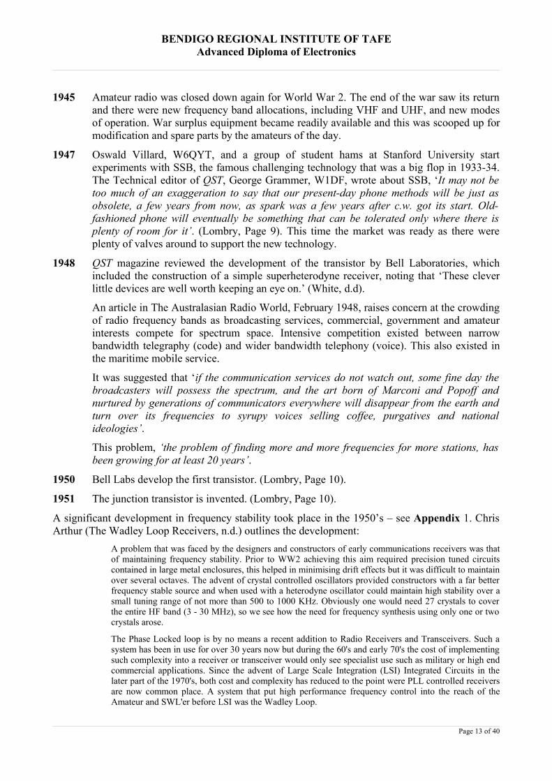
During WW2, while working on a wavemeter project a "Dr Trevor Wadley" developed a unique circuitfor cancelling frequency drift, a circuit later to be known as the Wadley Loop. The first well knownimplementation of Wadley's Loop was during the 1950's in the development of the Racal RA-17, asshown above. The RA-17 and later RA-117 where quite unique receivers, gaining extensive use by theBritish military from the late 1950's and through the 60's, in fact the 117 made it into the early 70's.
The RACAL RA-17 based on theWadley Loop, drift cancellingcircuit developed by Dr. TrevorWadley.
The future development of the Phase-Locked Loop and other digital techniques eventuallysurpassed the effectiveness of the Wadley Loop.
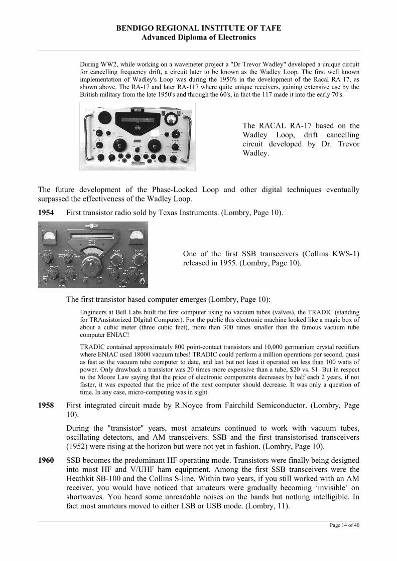
1954 First transistor radio sold by Texas Instruments. (Lombry, Page 10).
One of the first SSB transceivers (Collins KWS-1)released in 1955. (Lombry, Page 10).
The first transistor based computer emerges (Lombry, Page 10):Engineers at Bell Labs built the first computer using no vacuum tubes (valves), the TRADIC (standingfor TRAnsistorized DIgital Computer). For the public this electronic machine looked like a magic box ofabout a cubic meter (three cubic feet), more than 300 times smaller than the famous vacuum tubecomputer ENIAC!
TRADIC contained approximately 800 point-contact transistors and 10,000 germanium crystal rectifierswhere ENIAC used 18000 vacuum tubes! TRADIC could perform a million operations per second, quasias fast as the vacuum tube computer to date, and last but not least it operated on less than 100 watts ofpower. Only drawback a transistor was 20 times more expensive than a tube, $20 vs. $1. But in respectto the Moore Law saying that the price of electronic components decreases by half each 2 years, if notfaster, it was expected that the price of the next computer should decrease. It was only a question oftime. In any case, micro-computing was in sight.
1958 First integrated circuit made by R.Noyce from Fairchild Semiconductor. (Lombry, Page10).
During the "transistor" years, most amateurs continued to work with vacuum tubes,oscillating detectors, and AM transceivers. SSB and the first transistorised transceivers(1952) were rising at the horizon but were not yet in fashion. (Lombry, Page 10).
1960 SSB becomes the predominant HF operating mode. Transistors were finally being designedinto most HF and V/UHF ham equipment. Among the first SSB transceivers were theHeathkit SB-100 and the Collins S-line. Within two years, if you still worked with an AMreceiver, you would have noticed that amateurs were gradually becoming ‘invisible’ onshortwaves. You heard some unreadable noises on the bands but nothing intelligible. Infact most amateurs moved to either LSB or USB mode. (Lombry, 11).
Page 14 of 40

BENDIGO REGIONAL INSTITUTE OF TAFEAdvanced Diploma of Electronics
Hugh (Hughs Ominous Valve Works (n.d)) creates a snapshot of the state-of-the-art as itexisted in the 1960’s:
After World War II, HF voice radio started out pretty much with pre-war AM technology, but soonbegan the slow conversion to the far more efficient SSB. It's true that hams invented sideband, but notthat they perfected it. The phone company was using it in the 1930s. The ARRL pushed hard for itsadoption after the war, but the real impetus for conversion came when General Curtis "Iron Ass" LeMaygot the U.S. Air Force to adopt sideband for all of its HF communications. After this, it was only amatter of time for hams, and just about everyone else on HF. AM didn't die out completely, and itremains a fine ragchewing mode and a viable hobby within a hobby, but for most hams the quack-quacksound became far more prevalent.
SSB required some circuit changes in receivers, but nothing fundamental. The BFO had to be refined,filter passbands had to be adjusted, AVC had to be tweaked, and ultimately product detectors replacedsimple diodes. Stability, both mechanical and electrical, needed a magnitude of improvement. Thecommon solution was a multiple conversion/ fixed HFO/ narrow-range PTO/ high first IF/ low last IFdesign, as pioneered by Collins. The signal flow of the receiver remained essentially unchanged from the1930s, as it still does in today's superheterodynes.
Transmitters, however, needed a complete rethinking. For most hams, transmitters had always been morefun than receivers. They were simpler, and way easier to work on. Also, they tended to look like seriousequipment, which they were. They could even kill you. Most transmitters were relatively simpleoscillator/ multiplier/ driver/ PA chains, with class B modulators.
However, SSB required considerably more complex designs, with filters or phase-shift networks to getrid of the carrier and unwanted sideband. Modulation took place at low level, early in the signal chain,and this modulated signal was heterodyned to the working frequency. PA's were set linear, instead of themore efficient class C. This design approach involved severe compromises to AM operation, and to alesser extent CW, both of which are still way more fun on the 'boat anchors.' The ham radio became acomplex mass of critically aligned circuits, best adjusted by trained techs. The average ham, even thetechnically aware one, couldn't just tweak a tx by ear anymore.
Even so, the 60s began the gradual acceptance of small, self-contained transceivers, which could share alot of the same mixer and filter circuits. Within a decade, these had replaced the roomfuls of equipmentonce associated with short wave radio. By the mid-70s, vacuum tubes remained a viable design approachonly in the largest, external, linears, where they were a cheap, rugged alternative to high current, solid-state devices. Boat anchor linears, using heavy-duty components and commercial-grade output tubes, arevery much with us today.
The E.F. Johnson Viking Ranger transmitter manufacturedbetween 1954 and 1961. It operates between 160 and10m, including the 11-meter band, with 75 W in CW and65 W in AM. (Lombry, Page 11).
The Rhododendron Swamp VHF Society in Massachusetts succeeded in workingMoonbounce (reflecting radio signals from the moon) on 1296 MHz. (Lombry, Page 11).
1961 A group of American amateurs built and launched the very first Amateur Radio satelliteOSCAR 1, standing for Orbiting Satellite Carrying Amateur Radio, a term that is still usedtoday to identify most Amateur Radio satellites. It was launched on December 12, barelyfour years after the launch of Russia's first Sputnik. A 140 mW, 144.983 MHz transmitterthat discharged its non-rechargeable batteries after only three weeks of operation. It re-entered the earth’s atmosphere on January 31, 1962 after 312 revolutions. It was followedsix months later by the launch of OSCAR 2, using a design almost similar (Lombry, Page11). More than 70 amateur satellites would be launched within the next four decades.
Page 15 of 40

BENDIGO REGIONAL INSTITUTE OF TAFEAdvanced Diploma of Electronics
1968 SSTV (Slow Scan TV) was authorized by the FCC. This new digital mode permitted theamateur to transmit and receive still black and white or colour pictures. SSTV uses abandwidth of 3 kHz on dedicated frequencies and quite specialized equipment (camera,modem, software, etc). Standard vidicons were developed the same year by WB8DQT andK7YZZ. (Lombry, Page 12).
1970 The first FM repeaters emerge. The 10m band is the only HF band in which FM ispermitted and even so, the bandwidth is less than that permitted on VHF and UHF.
Japanese equipment continues penetration of the market. While Kenwood introduced itsJR-500SE receiver and prepared the blue prints of its first transmitter (TS-120S in 1979),in less than 6 months Yaesu released two transceivers, the FTDX-560 and FT-101. InAmerica, Drake released its Drake TR-4, Henry Radio introduced its Tempo-Onetransceiver and Heath announced the HW-100 and soon after the HW-101, two traditionaltube-type SSB transceivers. (Lombry, Page 13).
The Drake TR-4C transceiver (Lombry, Page13).
1978 Doug MacDonald Lockhart, VE7APU, adapted the concept of the packet mode oftransmission to ham activities. Until then it had been used in computing networks.(Lombry, Page 13).
As displayed at left, you need a computer, a digital interface(Pakratt, Rigblaster, etc) and any HF or VHFtransceiver. (Lombry, Page 13).
1980 The 1980’s allowed amateurs to use digital modes on all frequencies. The Internet andhome computers were gathering popularity and, with some amateurs at least, began tomerge with amateur radio.
Peter Martinez, G3PLX, developed AMTOR (Amateur Teleprinting Over Radio).(Lombry, Page 14).
Amateur Radio research and Development Corporation (AMRAD), in collaboration withAMSAT (amateur satellite organization) organized the first amateur radio computernetworking conference. At the same time the Tucson Amateur Packet Radio (TAPR)prepared the first terminal node controllers. It was followed by the development by theVancouver Amateur Digital Communication Group (VADCG), of the first Terminal NodeController (TNC), also known as the VADCG board. (Lombry, Page 14).
Page 16 of 40

BENDIGO REGIONAL INSTITUTE OF TAFEAdvanced Diploma of Electronics
Packet radio provides a lot of different operating opportunities. In the '80s it was limited toa TNC linking a computer to a VHF transceiver, base or hand-held. Then it was interfacedto Bulletin Board Systems (BBS) so that amateurs could send and receive personalmessages to and from their colleagues. (Lombry, Page 14).
1981 Not less than 8 amateur satellites were launched successfully. (Lombry, Page 14).
1990 Lombry (Lombry, Page 15) outlines DSP developments:In a time of computers, modems and digital transceivers, amateurs looked for a conversationalcommunications means like RTTY, but somewhat upgraded and taking advantage of the latest digitaltechnologies like DSP and FFT. The 1960 teleprinter for example could be replaced by the screen of acomputer and the teletype interface with a modem or similar interface - and a HF transceiver. Astransceivers were now more stable in frequency, the bandwidth could be much narrower. (Lombry, Page15).
In the beginning of '90s, the Polish amateur, Pawel Jalocha, SP9VRC, had already developed variousDSP systems (noise suppressor, Q15X25, FSK interface for Fax, etc) and Peter Martinez, G3PLX whodeveloped AMTOR, used these concepts to create PSK31, standing for "Phase Shift Keying, 31 bauds",a new digital mode more suited to the "computer assisted amateur". PSK31 kept some concepts of itsancestor, like the shifted keying of RTTY, now phase shifted instead of frequency shifted, the low speed,a very short transmission delay (400-800 ms), the lack of error-checking, and the mandatory keyboardinterface. Its bandwidth dropped from approximately 120 kHz for RTTY to as narrow as 31.25 kHz inPSK31.
A typical packet installation - a dedicated 2mtransceiver, the interface and a computer. (Lombry,Page 15).
In addition to RTTY, AMTOR, PSK31 and Packet there is a plethora of other digital modes developed.OH2AQ, and his team, provide on their website what we call "spots information" displaying in real-timea summary of contacts established on various bands and modes.
A cluster or node is a computer system connected to the Internet on one side and to radio receivers onthe other side using VHF (2m) or UHF (70 cm) packet connections. In the field, these computers areconnected to one or more dedicated transceivers, themselves connected to a TNC (e.g. Pakratt orRigblaster), a sort of multimode modem able to process high tones if its bandwidth is large enough. Theinformation is transmitted in small packets, hence its name (see '80s).
Licensed hams that have heard or worked a station and who want to publish the information for theinformation of the ham community have first to contact a near cluster using the TNC connected to their2m or 70cm transceiver or using their Internet connection to a dedicated website like OH2AQ.
1996 Digital Radio Mondiale, (DRM – digital transmission/reception over long wave, mediumwave and shortwave bands) emerged from an informal meeting in Paris, France, betweensome of the large international broadcasters and broadcasting equipment manufacturers.This new mode did not become a reality until 2003. (Lombry, Page 16). RFI, noises andfading problems were expected to disappear with this development.
Page 17 of 40

BENDIGO REGIONAL INSTITUTE OF TAFEAdvanced Diploma of Electronics
WinRADIO, an Australiancompany, released the firstdigital radio receiver, WR-G-303i. An HF interface card isinstalled in a PCI slot of yourcomputer and includes a dual-conversion superheterodynereceiver with software-definedlast IF stage and demodulator.
The WinRADIO digital radio interface as it appears on a computer monitor. (Lombry, Page 16).
Most if not all radio cards are now capable of receiving LW, MW and SW in most modes(AM, FM, USB, LSB, CW) and soon in DRM (Digital Radio Mondiale) mode, while themore sophisticated cards cover SHF frequencies up to 4 GHz. (Lombry, Page 16)
2002 Echolink, a computer program using the Voice-over-Internet Protocol, VoIP for short, toestablish long-distance communications is developed by Jonathan Taylor, K1RFD.(Lombry, Page 18). This digital method uses the Internet as a means of conveying the radiosignal around the world.
There has been a myriad of radio technology developments since it was discovered some 2,600years ago that static electricity could be generated by rubbing amber with cloth. Initially, progresswas slow and developments were few and far between. The last 100 years has seen technologyadvance at an ever-increasing rate to the point where it is now almost impossible to keep up with it.
Amateur radio commenced about 100 years ago as an unregulated hobby activity with a singleequipment choice - a spark transmitter and a coherer. The development of the vacuum tube or valveand modulation techniques, as well as the regulation of the hobby, saw the spark transmitter andcoherer consigned to the museum shelves in only a few years. This was the first case of the amateurhaving to update or retire from the hobby.
As the years passed, radio frequency bands became crowded with broadcasters, commercial,government and amateur stations as they all searched for a clear spot for their transmissions.Convenience and necessity drove the development of supporting technologies for modulationmethods and equipment.
Valves started to give way to semiconductors in the 1950’s except for high power requirements.Semiconductor integrated circuits began to combine many transistors in miniature encapsulated,multiple pin building blocks and amateurs launched the first of many of their own satellites in the1960’s. Digital electronics realised the digital frequency synthesiser, digital frequency displays,memories and scanning. Digital communication modes gathered popularity in the 1980’s and, withthe advent of the personal computer and merging technologies, a computer or at least amicroprocessor, has now become an integral part of all commercially manufactured amateurtransceivers. Modern transceivers have in-built personal computer interfaces for digital modesupport and DSP modules.
Page 18 of 40

BENDIGO REGIONAL INSTITUTE OF TAFEAdvanced Diploma of Electronics
The connection between each end of a communication link has gone through many developments injust over a century. It started with a necessary piece of wire, then to radio waves and along the waybranched off into intermediate links such as the moon (EME or earth-moon-earth), aircraftreflection, repeaters, satellites, and the Internet.
Amateur radio has gone from a period where most of the equipment had to be home made. Manyamateurs were at the forefront of technology and some of them have even been credited with someof the documented discoveries. New technologies in the latter half of the 1900’s, such asminiaturisation and microprocessor control made it more and more difficult for progressiveamateurs to make their own equipment. Many became alienated by the amount of circuitry that washidden from their sight encapsulated in blobs of plastic. Up to then they were able to see and handleevery individual component within their equipment. It was foreign to them to consider newcomponents simply as building blocks.
Specialised components required for the repair of older equipment or the building of replacementequipment based on tried and proven, well known older designs, are becoming scarce as it becomesmore and more uneconomical to manufacture them.
Amateurs have long been known for their ability to troubleshoot and repair their equipment. Currentcircuit complexity and component miniaturisation has forced most owners to return to the dealerexcept for the most basic of repairs and/or modification.
The modern HF transceiver (nominally bands within the frequency range of 0 to 30MHz) is a verycomplex product that contains numerous digital signal processing modules – usually in the last IFstage. The transmitter section must be able to handle 100% duty cycle digital modes. The receiversection must be able to handle a wide range of signal frequencies, modes and signal strengthsvirtually undreamed of 100 years ago. Sensitivity and selectivity are prime features. Like almosteverything else in this mass production, commerce driven age, facilities and conveniences can selland the discerning amateur will be comparing specifications and user conveniences.
Although the amateur radio market is not the bread and butter of the major manufacturers, if theywish to cater for the market they must provide a widerange of models. Today’s amateur indulges in one or morefixed station, mobile, portable, high power, low power,single band, multiband, single mode and multimodeactivities. They can be further categorised into two groups– casual or serious DX (long distance) award chasing.
The majority of amateurs, when looking at upgrading theirequipment, almost universally purchase new and there is
considerable brand loyalty.
The first Swan transceiver model SW-120 covering 14.2MHz to 14.35MHz only manufactured in1962.
There are many major players from years past that are almost never heard of these days except innostalgic discussions. The most predominant manufacturers of the 1950’s and 1960’s wereAmerican such as Barker & Williamson, Central Electronics, Collins Radio Company, E.F. Johnson
Page 19 of 40
BENDIGO REGIONAL INSTITUTE OF TAFEAdvanced Diploma of Electronics
Company, Gonset Company, Hallicrafters, Hammarlund, The Heath Company, National RadioCompany and R.L. Drake. According to Hugh (Hughs Ominous Valve Works (n.d)) all exceptDrake gradually folded, were taken over or moved into other fields.
The mainstream manufacturers today, at least as far as brands commonly available in Australia, areconcerned, are Yaesu (Vertek), Icom, Kenwood (all Japanese) and Ten-Tec (American). There arealso many smaller manufacturers such as MFJ and AOR making a variety of wide-range scanners,receivers and amateur accessories.
The modern amateur HF transceiver.
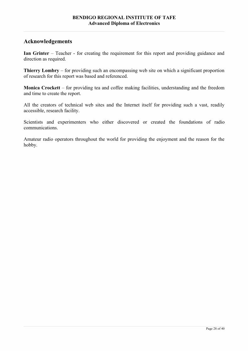
What, exactly, is it? The just released ICOM IC-7800 is an example of a top-level, modern, state-of-the-art transceiver. ICOM claims that the IC-7800 is the most advanced amateur radio ever. (It mayvery well be the most expensive ever produced as it is priced in excess of $AUD18,000.00). It hasfour 32-bit floating point DSP chips, two completely independent receivers, 7-inch wide TFTdisplay, RTTY/PSK31 encoder and decoder and compact flash technology. See Appendix 2 formore pre-release details.
Of course, it is not necessary to purchase the most expensive transceiver to enjoy the hobby. Vertek,who now manufacture the Yaesu brand, have a model FT-847 “Earth Station” with a specialsatellite mode and many other facilities and conveniences. This model is currently available for$AUD2,500.00 or around one eighth of the IC-7800 price. It is claimed by the manufacturers to bethe first HF/VHF/UHF all-mode transceiver with the versatility of covering every modern operatingmode. See Appendix 3 for details.
What real advances have occurred with recent technological developments? It is obvious that almostany improvement on the spark transmitters of old would be welcomed. Indeed, it eventually becamenecessary due to legislation. How much more desirable is a modern transceiver over one producedaround 25 years ago? The prices have slowly increased but dollar for equivalent dollar there areprobably more facilities available today with the economical advantages of computer design andmanufacture.
The table in Appendix 4 provides a comparison of specifications of two modern transceivers andone that is almost 25 years old. It is necessary to view the specifications with an understanding ofthe fundamental differences between the three transceivers shown. The ICOM IC-7800 is a veryexpensive state-of-the-art 2004 design. The YAESU FT-847 is around one eighth of the price and isdesigned with satellite operating convenience in mind. The YAESU FT-107M would beapproximately similar to the FT-847 as far as technology allowed in the pre-DSP 1980’s and itoperates on amateur band frequencies only.
A casual amateur might be forgiven for assuming that modern technology should automaticallymean better. After all, his requirements are considerably less stringent than for the serious operatorwho is looking for and attempting to extract the utmost in performance from his station. On thisbasis, it is assumed that almost any model, providing it has sufficient facilities for his area ofinterest, will suffice for the casual operator. After all, he is not looking for that competitive edge inoperation.
The serious amateur will not be so easily satisfied. He will be looking for optimum performance andwill be considering those design elements that will give him an edge in a competition environment.Assuming that the chosen transceiver has the appropriate mode capability and power output, thisedge relates to ease of operation, automation, weak signal handling capabilities and freedom fromthe adverse affects of close by, unwanted transmissions.
Page 20 of 40
BENDIGO REGIONAL INSTITUTE OF TAFEAdvanced Diploma of Electronics
Are current transceivers an automatic better choice for the serious amateur?
Lombry (Lombry Hardware Review n.d.) poses a number of questions in developing an appropriateconclusion.
What features make the difference between a mid-range and a high-end model?
Is the price a good indicator?
Are DSP functions useful?
Is it better to install mechanical filters or DSP filtering?
Is the selectivity and 3rd-order IMD important?
Sensitivity and Selectivity
The most important module in a transceiver, after the transmitter, is the receiver. It is quite easy totransmit a signal but you will never know if you have been heard unless you are able to at least hearthe reception report from the recipient. The receiver’s sensitivity is a measure of its ability to detecta useable weak signal. Four things can combine to make this a difficult task. These are atmosphericnoises picked up by the antenna along with the wanted signal, random noise contributed by theelectronic components of the receiver, the strength (or weakness) of the signal itself and degradationof that signal by the effects of close-in, stronger signals. The noise contributed by the receivercomponents is called the noise floor, below which a signal is not discernible.
The closer a signal’s strength to the noise floor, the more difficult it is for the receiver to reproduceit. Therefore, the lower the noise floor, the more sensitive the receiver.
Selectivity is a measure of the receiver’s ability to discriminate between wanted and unwantedtransmissions or its ability to reject those signals that are not of current interest to the listener.
Tadeusz Raczek (Raczek: Sept/Oct 2002) considers ARRL laboratory comparison test results froma number of modern receivers and casts doubt on the credibility of manufacturers’ sensitivity andblocking testing procedures. Manufacturers are catering for a wide clientele but the avid DX-er islooking for real performance on weak signals The manufacturers’ testing regime provides moreoptimistic results than the procedures applied by amateurs in the ARRL laboratory. The amateurs’regime more realistically approximates real world situations.
In his comparison between a number of modern transceivers, Raczek (Razcek: Sept/Oct 2002)makes some pertinent comments about sensitivity, BDR (Blocking Dynamic Range) and IMD DR(Intermodulation Dynamic Range):
We can presume that almost any modern HF receiver has enough sensitivity and selectivity to copy theweak DX station with no other signals present. Nevertheless, for real, on-the-air situations when plentyof strong signals are present near DX-station frequencies, some receivers will do better than the others.That will depend on how great is their BDR, how great is their IMD DR and how much phase noiseaccompanies the LO for any particular HF transceiver.
If the receiver has only average BDR, even a single adjacent signal … if it is strong enough willdesensitise the that receiver and the weak DX station will not be heard in the presence of stronginterference.
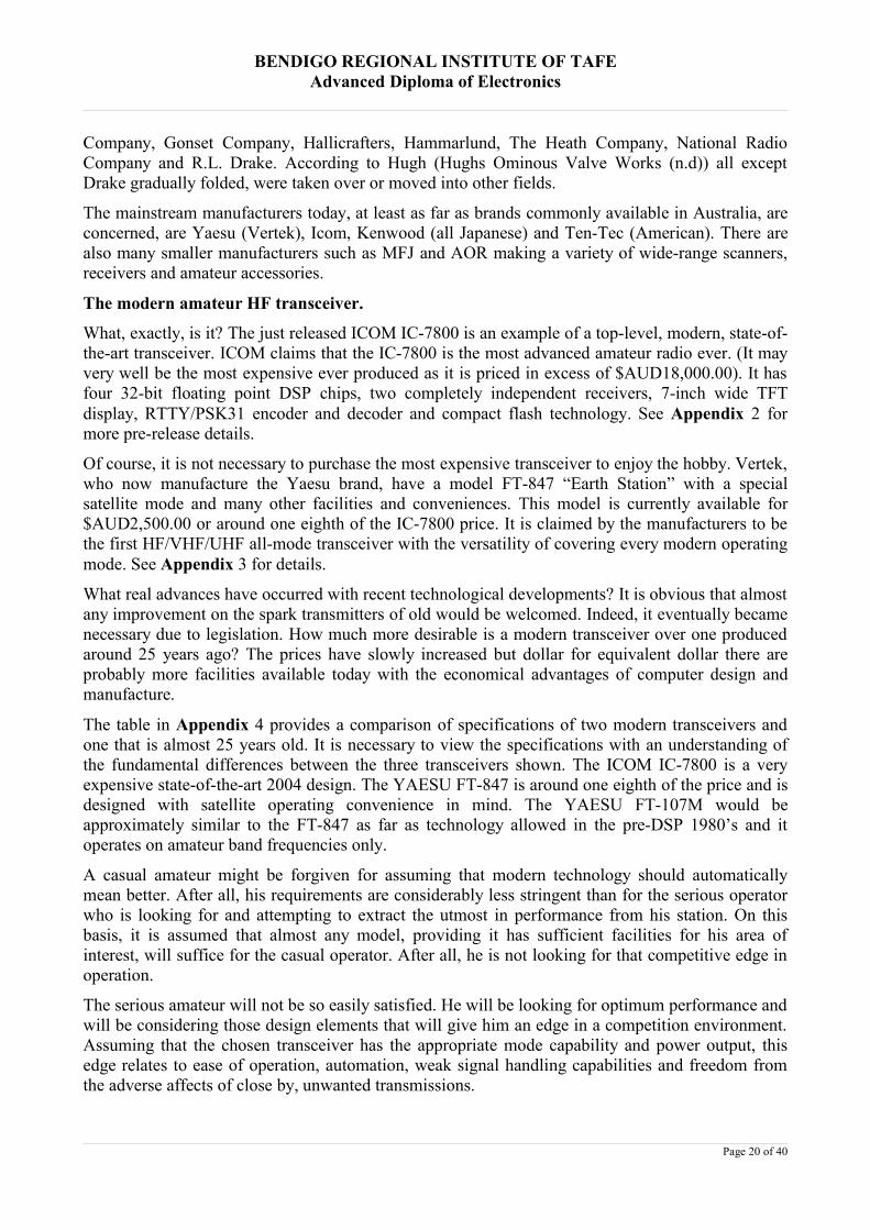
Raczek (Raczek: Sept/Oct 2002) provides the following table of receiver front-end dynamic-rangemeasurements performed by the ARRL laboratory at various signal spacings:
Page 21 of 40
BENDIGO REGIONAL INSTITUTE OF TAFEAdvanced Diploma of Electronics
The measurements show a considerable difference between the 5kHz and 50kHz signal spacings.
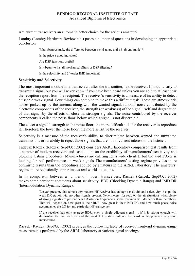
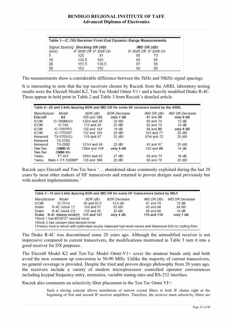
It is interesting to note that the top receivers chosen by Raczek from the ARRL laboratory testingresults were the Elecraft Model K2, Ten-Tec Model Omni-V1+ and a heavily modified Drake R-4C.These appear in bold print in Table 2 and Table 3 from Raczek’s detailed article.
Raczek says Elecraft and Ten-Tec have ‘… abandoned ideas commonly exploited during the last 20years by most other makers of HF transceivers and returned to proven designs used previously butwith modern implementations.’
The Drake R-4C was discontinued some 20 years ago. Although the unmodified receiver is notimpressive compared to current transceivers, the modifications mentioned in Table 3 turn it into agood receiver for DX purposes.
The Elecraft Model K2 and Ten-Tec Model Omni-V1+ cover the amateur bands only and bothavoid the now common up conversion to 50-90 MHz. Unlike the majority of current transceivers,no general coverage is provided. Despite the tried and proven design philosophy from 20 years ago,the receivers include a variety of modern microprocessor controlled operator conveniencesincluding keypad frequency entry, memories, variable tuning rates and RS-232 interface.
Raczek also comments on selectivity filter placement in the Ten-Tec Omni VI+:Such a mixing concept allows installation of narrow crystal filters in both IF chains right at thebeginning of first and second IF receiver amplifiers. Therefore, the receiver main selectivity filters are
Page 22 of 40
BENDIGO REGIONAL INSTITUTE OF TAFEAdvanced Diploma of Electronics
close to the mixers, where they should be according to Dxers – and where they are not in most ham radioHF transceivers made in the last 20 years.
Page 23 of 40

BENDIGO REGIONAL INSTITUTE OF TAFEAdvanced Diploma of Electronics
Conclusion
Having considered the preceding comparisons, it is obvious that the suitability, or otherwise, of amodern transceiver will depend on the requirements of the potential purchaser. The size of thepurchase budget would also be a moderating factor.
A serious DX-er has conflicting requirements. Is sensitivity and selectivity more important thanoperator convenience – especially when modern transceivers have so much automated logging andcontest participation facilities? Automation might enable a high turnover rate of contacts andtherefore enhance contest scoring. A lack of sensitivity and selectivity might also permit weaksignals to pass by undetected.
The casual operator has possibly the best of both worlds. Operator convenience and facilities will bemore attractive. After all, if contesting ability is not paramount, what does it matter if the transceiveris a little light on in this area?
What does a limited budget do to the decision? Here is a balancing act between affordability andsatisfying requirements. It will probably be seen that wide frequency coverage, convenience andfacilities are more important than the nth degree of performance. If the budget is limiting, wouldn’tyou want to ensure that you could do as much with the purchase as possible?
In making the final purchase decision, it is necessary to consider an increasingly wide range ofproducts with varying performance specifications and, perhaps, a bewildering array of what istermed ‘bells and whistles’. Be aware that manufacturers are trying to cater for a mass market andneed to recover research and development costs. They will be trying to attract you to their particularproduct with glossy brochures and other marketing ploys.
The process can be simplified a little by:
Identifying your budget constraints.
Identifying the critical performance criteria.
Researching those products that are within your budget and that satisfy the critical performancecriteria.
Comparing secondary facilities and conveniences from your research.
Ultimately, an understanding of the meaning of the many specifications, and their importance, maybe necessary to ensure the best decision.
If you are casual operator and your decision is not restricted by budget, purchase whatever you canafford and try to get the best-perceived value for the price.
If you are a serious contester, research the important specifications for your particular area ofinterest. An older transceiver may have superior performance for your budget. If your budget is nota limiting factor, be prepared to pay at least $AUD9,000.00 if you are going to purchase a modern,amateur band only transceiver.
Page 24 of 40
BENDIGO REGIONAL INSTITUTE OF TAFEAdvanced Diploma of Electronics
Research for this report has uncovered an emerging technology that may well bring about anincrease in amateur construction activity, although part of the construction will require someexpertise that many simply will not have. This emerging technology is Software Defined Radio orSDR and has been brought about by the convergence of computers, digital electronics and theincreasing need for radio communication and bandwidth economies.
The International Amateur Radio Union, IARU, (IARU – International Amateur Radio Union (20February 2002)) indicates that once again, amateurs are at the forefront of the development of radiocommunication technologies.
As we enter radio's second century, amateurs continue to lead the way in numerous areas.
Digital HF Radio: Radio amateurs are the leading developers of new digital techniques for high-frequency (HF)data and text communication. For example, PacTOR combines the strengths of packet radio and the mode knowncommercially as SITOR to offer reliable and essentially error-free data communication. Disaster relief agencieshave adopted it for use from remote locations where no telecommunications infrastructure is available. PSK31 isa user-friendly mode that provides live keyboard communication at low transmitter power levels when errorcorrection is not required. An implementation of PSK31 using computer sound cards has made this the mostpopular digital mode for radio amateurs in less than two years. Other developers, building on the success ofPSK31, are using sound cards to explore a wide range of other digital modes tailored for the challenging HFenvironment.
Software Defined Radios: Perhaps the outstanding example of a DSP radio designed for experimental use is theDSP-10, a transceiver for the 144-MHz amateur band designed by Bob Larkin, W7PUA, of Corvallis, Oregon,USA. Working with Mr. Larkin, a team of amateur software developers is refining a family of programs tailoredto explore a wide range of VHF, UHF, and microwave propagation media, including moonbounce (Earth-Moon-Earth) and extended-range tropospheric scatter. These are but examples of what is happening in the 21st CenturyAmateur Radio Service.
A personal computer is basically a machine whose output is entirely dependent on the softwareprogram that drives it. A change or upgrade of software can result in an entirely different outputwithout changing any of the physical components of the computer. The same computer can be aspreadsheet, a database or a CD player – it all depends on the software.
SDR is basically similar. A black box contains a limited amount of electronics to capture anddigitise a received signal. The digitised signal is then fed to a personal computer whose softwareand sound card determine what is done with the signal. This allows virtually unlimited applicationof digital signal processing technology. Once the black box is constructed, it is only necessary tomodify or upgrade the software to bring about different transmitter or receiver functions.
The black box is not a transceiver. It is simply a black box that could just as easily be configured tobe a digital telephone, a signal generator or anything else the software could bring about.
The ultimate goal is to position the digitising technology as close to the antenna connection aspossible.
Page 25 of 40
BENDIGO REGIONAL INSTITUTE OF TAFEAdvanced Diploma of Electronics
ReferencesARRL West Hartford, Connecticut, USA, QST December 1915 (Fortieth AnniversaryReproduction), QST, December 1955.
Columbia University (2002) Living Legacies, Yannis Tsividis [on line] Available:http://www.columbia.edu/cu/alumni/Magazine/Spring2002/Armstrong.html. [Accessed 24 May2004].
Gazard, John, (1985), The Technical Side of Early Amateur Radio, Amateur Radio, June 1985,Wireless Institute of Australia.
Hughs (sic) Ominous Valve Works (n.d.) Boat Anchor Manufacturers [on line] Available:http://www.ominous-valve.com/ba-mfrs.html. [Accessed 24 May 2004]
IARU – International Amateur Radio Union (20 February 2002) News Release: World AmateurRadio Day Celebrates Amateurs' Continuing Innovation in Communication Technology [on line]Available:http://www.iaru.org. [Accessed 13 May 2004]
Raczek, Tadeusz – SP7HT (Sept/Oct 2002) DX Prowess of HF Receivers [on line]Available:http://www.astrosurf.com/lombry/Radio/DXProwessofHFreceivers-qex-sep-oct2002.pdf.[Accessed 31 May 2004]
Lombry, Thierry - ON4SKY (n.d) Hardware Review [on line]Available:http://www.astrosurf.com/lombry/qsl-transceiver.htm. [Accessed 31 May 2004]
Lombry, Thierry - ON4SKY (n.d) Page 1: The Time of Discoveries [on line]Available:http://www.astrosurf.com/lombry/qsl-ham-history.htm. [Accessed 28 April 2004]
Lombry, Thierry - ON4SKY (n.d) Page 2: Birth of ITU - 1852-1887 [on line]Available:http://www.astrosurf.com/lombry/qsl-ham-history2.htm. [Accessed 28 April 2004]
Lombry, Thierry - ON4SKY (n.d) Page 3: Marconi, Time for Business - 1894-1910 [on line]Available:http://www.astrosurf.com/lombry/qsl-ham-history3.htm. [Accessed 28 April 2004]
Lombry, Thierry - ON4SKY (n.d) Page 4: Ham, the poor operator - 1911-1913 [on line]Available:http://www.astrosurf.com/lombry/qsl-ham-history4.htm. [Accessed 28 April 2004]
Lombry, Thierry - ON4SKY (n.d) Page 5: The American Radio Relay League - 1912-1922 [on line]Available:http://www.astrosurf.com/lombry/qsl-ham-history5.htm. [Accessed 28 April 2004]
Lombry, Thierry - ON4SKY (n.d) Page 6: The 1920’s. The Discovery of HF and DXCommunications [on line] Available:http://www.astrosurf.com/lombry/qsl-ham-history6.htm.[Accessed 28 April 2004]
Lombry, Thierry - ON4SKY (n.d) Page 7: The 1930’s. The Great Depression [on line]Available:http://www.astrosurf.com/lombry/qsl-ham-history7.htm. [Accessed 28 April 2004]
Lombry, Thierry - ON4SKY (n.d) Page 8: Birth of Radioastronomy 1932 [on line]Available:http://www.astrosurf.com/lombry/qsl-ham-history8.htm. [Accessed 28 April 2004]
Lombry, Thierry - ON4SKY (n.d) Page 9: The 1940’s: All at war on single sideband [on line]Available:http://www.astrosurf.com/lombry/qsl-ham-history9.htm. [Accessed 28 April 2004]
Lombry, Thierry - ON4SKY (n.d) Page 10: The 1950’s. The King Transistor [on line]Available:http://www.astrosurf.com/lombry/qsl-ham-history10.htm. [Accessed 28 April 2004]
Page 26 of 40

BENDIGO REGIONAL INSTITUTE OF TAFEAdvanced Diploma of Electronics
Lombry, Thierry - ON4SKY (n.d) Page 11:Echos from Moonbounce to Sputnik [on line]Available:http://www.astrosurf.com/lombry/qsl-ham-history11.htm. [Accessed 28 April 2004]
Lombry, Thierry - ON4SKY (n.d) Page 12: The 1960’s. Megahertz and small steps [on line]Available:http://www.astrosurf.com/lombry/qsl-ham-history12.htm. [Accessed 28 April 2004]
Lombry, Thierry - ON4SKY (n.d) Page 13: The 1970’s. The FM Repeaters [on line]Available:http://www.astrosurf.com/lombry/qsl-ham-history13.htm. [Accessed 28 April 2004]
Lombry, Thierry - ON4SKY (n.d) Page 14: The 1980’s. Internet, packet radio and space [on line]Available:http://www.astrosurf.com/lombry/qsl-ham-history14.htm. [Accessed 28 April 2004]
Lombry, Thierry - ON4SKY (n.d) Page 15: The 1990’s. PSK31 and clusters [on line]Available:http://www.astrosurf.com/lombry/qsl-ham-history15.htm. [Accessed 28 April 2004]
Lombry, Thierry - ON4SKY (n.d) Page 16: HAREC and CEPT recommendations [on line]Available:http://www.astrosurf.com/lombry/qsl-ham-history16.htm. [Accessed 28 April 2004]
Lombry, Thierry - ON4SKY (n.d) Page 17: The 2000’s. WRC 2003 and the code-less license [online] Available:http://www.astrosurf.com/lombry/qsl-ham-history17.htm. [Accessed 28 April 2004]
Lombry, Thierry - ON4SKY (n.d) Page 18: Work the world with Echolink [on line]Available:http://www.astrosurf.com/lombry/qsl-ham-history18.htm. [Accessed 28 April 2004]
Lombry, Thierry - ON4SKY (n.d) The future of communications [on line]Available:http://www.astrosurf.com/lombry/qsl-future-communications.htm. [Accessed 28 April2004]
NMAH Archives Centre, (n.d) Radioana Collection, c. 1880 - 1950 George H. Clark [on line]Available: http://www.si.edu/lemelson/dig/radioana/index.html. [Accessed 10 May 2004]
The Australasian Radio World, February, 1948, Wanted – An Inventor, pub A.G. Hull, Mornington,reprint from QST.
The Australasian Radio World, November, 1948, The Man Before Marconi, pub A.G. Hull,Mornington, reprint from QST.
The Digital Ham Radio Revolution, (n.d.) [on line] Available:http://home.teleport.com/~nb6z/main.htm. [Accessed 04 July 2004]
The Wadley Loop HF Receivers (n.d.) Chris Arthur, VK3JEG [on line] Available:http://www.qsl.net/vk3jeg/b_wadley.html. [Accessed 11 June 2004]
White, Thomas (n.d) United States Early Radio History [on line] Available:http://earlyradiohistory.us/sec014.htm. [Accessed 9 May 2004]
WIA, Wireless Institute of Australia (n.d). WIA Book, Volume 1, ed Bruce Bathols, North Caulfield,Australia:Waverley Offset Publishing Group.
Page 27 of 40
BENDIGO REGIONAL INSTITUTE OF TAFEAdvanced Diploma of Electronics
Acknowledgements
Ian Grinter – Teacher - for creating the requirement for this report and providing guidance anddirection as required.
Thierry Lombry – for providing such an encompassing web site on which a significant proportionof research for this report was based and referenced.
Monica Crockett – for providing tea and coffee making facilities, understanding and the freedomand time to create the report.
All the creators of technical web sites and the Internet itself for providing such a vast, readilyaccessible, research facility.
Scientists and experimenters who either discovered or created the foundations of radiocommunications.
Amateur radio operators throughout the world for providing the enjoyment and the reason for thehobby.
Page 28 of 40

BENDIGO REGIONAL INSTITUTE OF TAFEAdvanced Diploma of Electronics
Appendix 1 - The Wadley Loop Drift Cancelling System
There were several different frequency schemes used by manufacturers who employed the Wadley Loop but the basicprinciple of operation is applicable to all. A further comment worth making is that the Wadley loop should not beconfused with a phase locked loop, both systems are quite different in operation. The following operational descriptionis for the Barlow Wadley XCR-30.
The Loop system uses a single 1 MHz crystal to generate harmonics at 1 Meg intervals, a double mixing process with atuneable 45.5 to 75.5 MHz oscillator provides 30 tuneable ranges from 500 KHz to 30 MHz. The outputs of the firstmixer (42.5 MHz) and second mixer (45 MHz) are amplified and then fed to a third mixer. With the 45 MHz Amphaving a flat band-pass range of 1 MHz the output of our 3rd mixer is 2.5 MHz +- 500 kHz. This 2 to 3 MHz signal isthen amplified and tuned with a 2.455 to 3.455 MHz mixer/oscillator, passing through a 455 kHz IF to the AM and SSBdetectors.
TheBarlow Wadley XCR-30
Who used the Wadley Loop?
During the mid 1970's, Wadley's loop system was employed by several manufacturers, such as Yaesu (FRG-7), Drake(SSR-1) and Realistic (DX-300) but little is known of the actual Barlow Wadley Receivers and for that matter theBarlows Television Company (The Wadley Loop HF Receivers n.d.).
Ian Pogson, VK2AZN, used the Wadley Loop system in his well known valve and solid-state Deltahet communicationsreceiver projects described in Australian magazine Electronics Australia in the 1960’s and 1970’s. Phase-Locked Loopand other digital technologies eventually rendered the Wadley Loop obsolete.
Page 29 of 40

BENDIGO REGIONAL INSTITUTE OF TAFEAdvanced Diploma of Electronics
Appendix 2 – ICOM IC-7800 Brochure Details
The just released ICOM IC-7800 is an example of amodern, top-level, state-of-the-art transceiver and thesedetails are taken from the pre-release brochure.
In the brochure, Icom claims to be the first manufacturer tobring transistor technology, digital PLL technology and thelatest DSP technology to name a few achievements. TheIC-7800 amateur transceiver is claimed to be the mostadvanced amateur radio ever. (It may very well be the most
expensive ever produced as it is priced in excess of $AUD18,000.00). It has four 32-bit floating point DSP chips, twocompletely independent receivers, 7-inch wide TFT display, RTTY/PSK31 encoder and decoder and compact flashtechnology.
Four 32-bit floating point DSP units
Four independent DSP units are used. One for the transmitter, one for each receiver, and the final one for thespectrum scope. The DSP units are combined with a 24-bit AD/DA converter to support many of the DSPfeatures exclusive to the IC-7800.
+40dBm ultra high intercept point
Icom has developed an amateur rig that challenges the performance of any “Military Grade” transceiver. A+40dBm* 3rd order intercept point and ultra wide dynamic range that is amateur radio’s highest. Mechanicalrelays instead of traditional semi-conductors and high performance DMOS mixers with a high-drive LocalOscillator. Two IF stages and Icom’s new image rejection technology, enables the IC-7800 to clearly reproducevery weak signals as well as very strong signals without distortion.
Automatic tracking pre-selector
The 7800’s pre-selector automatically tracks the intended signal, keeping the pre-selector’s bandwidth centeredon the operating frequency.
Two completely independent receiver circuits
Dual receivers are completely independent all the way from the 4 antenna jacks, through the pre-selectors, DSP,signal detectors, front panel control, right into the stereo headphone jack In addition to the separate receivers, theaudio amplifiers and control circuits are duplicated for either headphones or external speakers
200W output power at full duty
Newly designed push-pull MOS-FET amplifiers work with 48V DC, providing 200W of output power at full dutycycle with low IMD in all bands. A low-noise switching power supply is built-in.
Ultra high frequency stability
A standard stability of ±0.05ppm. Even on 6m band (52 to 54MHz), that is less than 3Hz error from the OvenControlled Crystal Oscillator. A 10MHz reference frequency can be input/output for external equipment.
7-inch wide color TFT LCD
A large 7-inch wide (800×480 pixels) color display. High linearity needle S-meters, multi-function spectrumscope and RTTY/PSK31 messages are displayed in vivid color. There is also a VGA connector allowingconnection to an external monitor.
Multi function spectrum scope
With the dedicated DSP unit, the spectrum scope offers linearity, accuracy and resolution. By adjusting the scopeselectivity (resolution band width), the spectrum scope allows selection of weak signals right next to strong ones.Monitoring the distortion or width of the received signals is also possible. The scope range can be setindependently from the receiving frequency. You can monitor the band condition between the selected sweepedges, as well as sweep a selected bandwidth centered on the receiving frequency in the scope screen.
RTTY /PSK31 operation without PC connection
Page 30 of 40

BENDIGO REGIONAL INSTITUTE OF TAFEAdvanced Diploma of Electronics
The IC-7800 has a modulator and demodulator for the 2 major HF Amateur digital modes. It is possible toencode and decode PSK31 as well as baudot RTTY signals by simply connecting a USB keyboard to thetransceiver. It is no longer necessary to connect a PC for RTTY/PSK31 operation. In addition, transmitted andreceived messages can be stored to the CF card memory and transferred to a PC.
IF notch filter with adjustable notch filter characteristics
The DSP controlled manual notch filter shape can be set in 3-steps for the various receiving conditions. Use a softfilter shape for tuning an interfered tone, then switch to the sharp one to cut 70dB off the tone.
Professional 6m receiver
Most HF/50MHz transceivers share the preamp between the HF bands and 50MHz band. The IC-7800 uses anexclusive preamp and mixer especially for 50MHz. The preamp and mixer are both tuned to the 50MHz band andimprove cross modulation characteristics, particularly important when picking up a very weak signal near a strongone.
Digital Voice Recorder
The Digital Voice Recorder (DVR) is a convenient function for contests, DX peditions, field days and evennormal operation. It will record callsign, CQ, or other station information into a memory. Independent Recordand Play buttons are on the front panel.
CF (Compact Flash) memory card
The IC-7800 has a CF card slot and a CF card will be supplied for storing various settings such as filter, display,mic equalizer, etc. When sharing the IC-7800 with multi-users such as on a DX pedition, in a contest or as a clubrig, the CF card allows instant restoration of personal settings.
And more....
• Soft and sharp IF filter shapes for receiver
• Synchronous AM detection
• Reverse power protection circuit built-in
• RS-232C port for PC connection
• BNC type RF accessory connectors
• Audio Peak filter for CW
• Multi-function noise blanker
• Advanced noise reduction and auto notch
• Twin peak audio filter and tuning indicator for RTTY
• High speed automatic antenna tuner
• Built-in Voice synthesizer
• Main/Sub receiver connectors
• Optional IC-PW1 1kW Linear Amplifier available
Page 31 of 40

BENDIGO REGIONAL INSTITUTE OF TAFEAdvanced Diploma of Electronics
Appendix 3 - Yaesu Musen FT-847 Earth StationThe 2004 version of the Vertek manufactured Yaesu FT-847 “Earth Station” with a special satellite mode and manyother facilities and conveniences is an example of a generalpurpose, modern multi-band and mode transceiver. Thismodel is currently available for $AUD2,600.00.
Yaesu claims to be the first manufacturer to produce a self-contained amateur HF transceiver, the first to produce anFM transceiver with memory and the first to produce a full-
duplex satellite transceiver. With the FT-847, they also claim to be the first to produce an HF/VHF/UHF all-modetransceiver with the versatility of covering every modern operating mode.
Optional Automatic Antenna Tuner
Analyses the impedance present at the radio end of the coax. Stepper motors adjust variable capacitors to match50 ohms. Includes 100 memories for tuning data.
Optional Active-Tuning Antenna System
The FT-847 can be expanded for mobile use on the 7/14/21/28/50/144/430 MHz bands. Controlled by a DCvoltage from the transmitter to adjust the single antenna to resonance in seconds.
Separate Antenna Connectors
Separate antenna connectors for HF, 50, 144 and 430 MHz to permit full-duplex operation. The 50MHzconnector can also be electronically switched to the HF section to permit the use of two antennas on the HFbands.
Cross-band full duplex operation
Effortless satellite operation whereby you can monitor the downlink signal from the satellite while simultaneouslytransmitting – only available if transmitting on one band while listening on another. Independent display of uplinkand downlink frequencies is possible.
Uplink/Downlink Normal and Inverted Tracking
Slaves the two VFO’s according to the requirements of the satellite’s transponder.
Satellite Convenience Features
Alphanumeric tags for labelling the 19 special satellite memories.
The satellite meter will indicate, power out, discriminator or ALC by selection.
Rear panel DATA IN/OUT and PKT jacks can accommodate 9600 GMSK, 1200bps PSK or 1200 bps AX.25AFSK modes.
All Mode Operation
All mode (SSB, CW, HSCW, AM, FM, Packet, SSTV and RTTY) operation on HF (100W), 50MHz (100W),144MHz (50W) and 430MHz (50W).
Advanced Digital Signal Processing
Independently adjustable audio high-pass and low-pass DSP filters.
A total of 16 DSP noise reduction parameters.
DSP Auto Notch Filter with instantaneous sensing and notching of multiple interfering signals.
DDS Synthesiser
A new generation ultra-low-noise Direct Digital Synthesiser local oscillator with tuning steps down to 0.1Hz forcareful tuning of EME signals, seamless Doppler shift during satellite work and effortless digital mode tuning.
Low-noise Receiving Pre-amplifiers
Page 32 of 40

BENDIGO REGIONAL INSTITUTE OF TAFEAdvanced Diploma of Electronics
Receive pre-amplifiers for all bands. The 430MHz band pre-amplifier is a 10db HEMT (High Electron MobilityTransistor) design
Push-Pull Cooling
Twin cooling fans. The front panel fan sucks cooling air in and directs it around the internal cooling ducts and therear fan forces it out the rear.
Additional Features
Expanded receive frequency range – 0 to 36MHz, 37MHz to 76MHz, 108 to 174MHz and 420 to 512MHz.
IF Shift for shifting the IF passband to avoid interference.
IF Noise Blanker for reduction of automotive ignition noise.
Input RF Attenuator – 20db reduction of signal.
Fixed level AF output jack for tape recorder or weather fax decoder.
Optional Collins mechanical filters
Built in RF type speech compressor.
10 key direct frequency entry keypad.
Built in RS-232C level converter for data transfer at 4800, 9600 or 57,600bps.
Optional voice frequency announcement module.
78 regular memories, upper/lower band/scanning limit memories, a Call channel, a Home channel on each band, asingle channel Quick Memory bank, 12 special Satellite memory channels.
Page 33 of 40
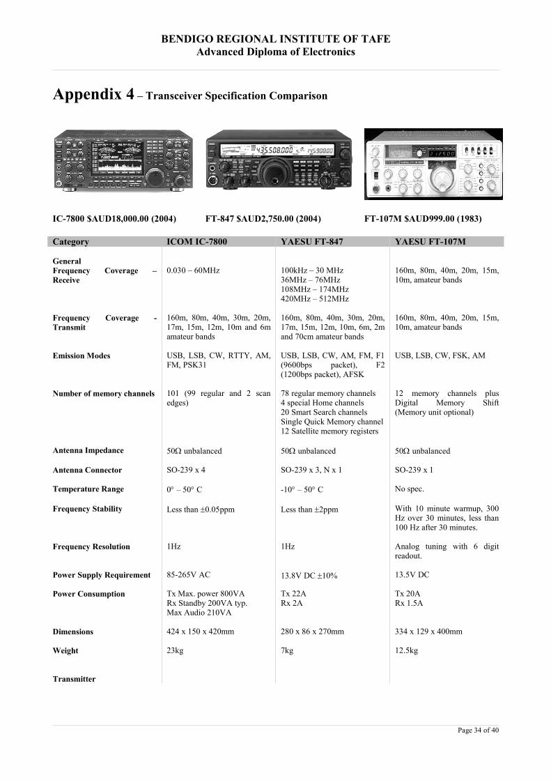
BENDIGO REGIONAL INSTITUTE OF TAFEAdvanced Diploma of Electronics
Appendix 4 – Transceiver Specification Comparison
IC-7800 $AUD18,000.00 (2004) FT-847 $AUD2,750.00 (2004) FT-107M $AUD999.00 (1983)
Category ICOM IC-7800 YAESU FT-847 YAESU FT-107M
GeneralFrequency Coverage –Receive
0.030 – 60MHz 100kHz – 30 MHz36MHz – 76MHz108MHz – 174MHz420MHz – 512MHz
160m, 80m, 40m, 20m, 15m,10m, amateur bands
Frequency Coverage -Transmit
160m, 80m, 40m, 30m, 20m,17m, 15m, 12m, 10m and 6mamateur bands
160m, 80m, 40m, 30m, 20m,17m, 15m, 12m, 10m, 6m, 2mand 70cm amateur bands
160m, 80m, 40m, 20m, 15m,10m, amateur bands
Emission Modes USB, LSB, CW, RTTY, AM,FM, PSK31
USB, LSB, CW, AM, FM, F1(9600bps packet), F2(1200bps packet), AFSK
USB, LSB, CW, FSK, AM
Number of memory channels 101 (99 regular and 2 scanedges)
78 regular memory channels4 special Home channels20 Smart Search channelsSingle Quick Memory channel12 Satellite memory registers
12 memory channels plusDigital Memory Shift(Memory unit optional)
Antenna Impedance 50 unbalanced 50 unbalanced 50 unbalanced
Antenna Connector SO-239 x 4 SO-239 x 3, N x 1 SO-239 x 1
Temperature Range 0 – 50 C -10 – 50 C No spec.
Frequency Stability Less than 0.05ppm Less than 2ppm With 10 minute warmup, 300Hz over 30 minutes, less than100 Hz after 30 minutes.
Frequency Resolution 1Hz 1Hz Analog tuning with 6 digitreadout.
Power Supply Requirement 85-265V AC 13.8V DC 10% 13.5V DC
Power Consumption Tx Max. power 800VARx Standby 200VA typ.Max Audio 210VA
Tx 22ARx 2A
Tx 20ARx 1.5A
Dimensions 424 x 150 x 420mm 280 x 86 x 270mm 334 x 129 x 400mm
Weight 23kg 7kg 12.5kg
Transmitter
Page 34 of 40
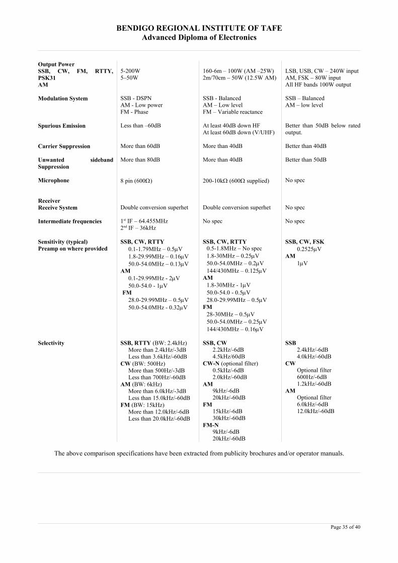
BENDIGO REGIONAL INSTITUTE OF TAFEAdvanced Diploma of Electronics
Output PowerSSB, CW, FM, RTTY,PSK31AM
5-200W5–50W
160-6m – 100W (AM –25W)2m/70cm – 50W (12.5W AM)
LSB, USB, CW – 240W inputAM, FSK – 80W inputAll HF bands 100W output
Modulation System SSB - DSPNAM - Low powerFM - Phase
SSB - BalancedAM – Low levelFM – Variable reactance
SSB – BalancedAM – low level
Spurious Emission Less than –60dB At least 40dB down HFAt least 60dB down (V/UHF)
Better than 50dB below ratedoutput.
Carrier Suppression More than 60dB More than 40dB Better than 40dB
Unwanted sidebandSuppression
More than 80dB More than 40dB Better than 50dB
Microphone 8 pin (600) 200-10k (600 supplied) No spec
ReceiverReceive System Double conversion superhet Double conversion superhet No spec
Intermediate frequencies 1st IF – 64.455MHz2nd IF – 36kHz
No spec No spec
Sensitivity (typical)Preamp on where provided
SSB, CW, RTTY0.1-1.79MHz – 0.5V1.8-29.99MHz – 0.16V50.0-54.0MHz – 0.13V
AM0.1-29.99MHz - 2V50.0-54.0 - 1V
FM28.0-29.99MHz – 0.5V50.0-54.0MHz - 0.32V
SSB, CW, RTTY0.5-1.8MHz – No spec1.8-30MHz – 0.25V50.0-54.0MHz – 0.2V144/430MHz – 0.125V
AM1.8-30MHz - 1V50.0-54.0 - 0.5V28.0-29.99MHz – 0.5V
FM28-30MHz – 0.5V50.0-54.0MHz – 0.25V144/430MHz – 0.16V
SSB, CW, FSK0.2525V
AM1V
Selectivity SSB, RTTY (BW: 2.4kHz)More than 2.4kHz/-3dBLess than 3.6kHz/-60dB
CW (BW: 500Hz)More than 500Hz/-3dBLess than 700Hz/-60dB
AM (BW: 6kHz)More than 6.0kHz/-3dBLess than 15.0kHz/-60dB
FM (BW: 15kHz)More than 12.0kHz/-6dBLess than 20.0kHz/-60dB
SSB, CW2.2kHz/-6dB4.5kHz/60dB
CW-N (optional filter)0.5kHz/-6dB2.0kHz/-60dB
AM9kHz/-6dB20kHz/-60dB
FM15kHz/-6dB30kHz/-60dB
FM-N9kHz/-6dB20kHz/-60dB
SSB2.4kHz/-6dB4.0kHz/-60dB
CWOptional filter600Hz/-6dB1.2kHz/-60dB
AMOptional filter6.0kHz/-6dB12.0kHz/-60dB
The above comparison specifications have been extracted from publicity brochures and/or operator manuals.
Page 35 of 40
BENDIGO REGIONAL INSTITUTE OF TAFEAdvanced Diploma of Electronics
Appendix 5 - Amateur Digital Communication Modes
Amateur digital (computer generated) communication modes have blossomed due to the generosityof amateurs with programming knowledge providing their software essentially free over the Internetand wide spread use of the Personal Computer with a digital sound card for the required DigitalSignal Processing required. HF digital operation today is distinguished by the use of lower powerand operating bandwidth.
The following explanation of digital modes is provided by (The Digital Ham Radio Revolution n.d.)
PSK31 mode led the way starting in 1997, and since then experimentation has shown that incrementalimprovements can be made. The popularity of a single mode, like PSK31, over other new modes seems to bedriven at this time by how many freeware programs are available for the mode. It is possible that a moreadvanced mode like MFSK16 will emerge as a standard for HF band operation in the future. We can allparticipate in the revolution by trying out the other modes and judging their performance on all of the HF bands.Fortunately, the interface needed to operate these new PC sound card programs is the same for all the modes. Thenext challenge for the ham programmers out there is to create a single program that will incorporate modules forall the new sound card modes.
Confusion over band space is the obvious downside as new and old modes compete for band space. Crowding ona single band like 20 meters is partly to blame for this issue. Fortunately, the new modes, like MFSK16, aredesigned to improve performance inside a wide range of operating conditions. This should allow for increasedham band usage to relieve crowding and extend contact opportunities as propagation changes to favor differentbands. I don't know what is going on with the phone portion of the ham bands, but these are exciting times for usdigital operators!
TOR is an acronym for Teleprinting Over Radio. It is traditionally used to describe the three popular "error free"operating modes, AMTOR, PACTOR and G-TOR. The main method for error correction is from a techniquecalled ARQ (automatic repeat request) which is sent by the receiving station to verify any missed data. Since theyshare the same method of transmission (FSK), they can be economically provided together in one TNC modemand easily operated with any modern radio transceiver. TOR methods that do not use the ARQ handshake can beeasily operated with readily available software programs for personal computers. For these less complex modes,the TNC (terminal node controller) is replaced by an on-board sound card or out-board audio device. Thesemodes may use redundancy or "human processing" to achieve a level of error correction.
AMTOR is an FSK mode that has been fading into history. While a robust mode, it only has 5 bits (as did itspredecessor RTTY) and cannot transfer extended ASCII or any binary data. With a set operating rate of 100baud, it does not effectively compete with the speed and error correction of more modern ARQ modes. The non-ARQ version of this mode is known as FEC, and known as SITOR-B by the Marine Information services.
PACTOR is an FSK mode and is a standard on modern TNCs. It is designed with a combination of packet andAmtor Techniques. It is the most popular ARQ digital mode on amateur HF today. This mode is a majoradvancement over AMTOR, with its 200 baud operating rate, Huffman compression technique and true binarydata transfer capability.
PACTOR-II is a robust and powerful PSK mode which operates well under varying conditions. It uses stronglogic, automatic frequency tracking; it is DSP based and as much as 8 times faster then Pactor. Both PACTORand PACTOR-2 use the same protocol handshake, making the modes compatible.
PACTOR-III is a proprietary mode used for message and traffic handling over an HF radio circuit. Use ofPactor-III protocol is limited for US hams and some other countries due to the very wide bandwidth of the Pactor-III signal. Presently digital signals that occupy the bandwidth of PCT-III are restricted to a few sub bands:28.120-28.189 MHz, 24.925-24.930 MHz, 21.090-21.100 MHz, 18.105-18.110 MHz, 14.0950-14.0995 MHz,14.1005-14.112 MHz, 10.140-10.150 MHz, 7.100-7.105 MHz, or 3.620-3.635 MHz. Only the embeddedhardware (modem) from the German company that owns the rights to this mode, is capable of operating Pactor-III.
G-TOR (Golay -TOR) is an FSK mode that offers a fast transfer rate compared to Pactor. It incorporates a datainter-leaving system that assists in minimizing the effects of atmospheric noise and has the ability to fix garbleddata. G-tor tries to perform all transmissions at 300 baud but drops to 200 baud if difficulties are encountered and
Page 36 of 40
BENDIGO REGIONAL INSTITUTE OF TAFEAdvanced Diploma of Electronics
finally to 100 baud. (The protocol that brought back those good photos of Saturn and Jupiter from the Voyagerspace shots was devised by M.Golay and now adapted for ham radio use.) G-tor is found in only onemanufacture's TNC and is rarely used today.
CLOVER is a PSK mode which provides a full duplex simulation. It is well suited for HF operation (especiallyunder good conditions), however, there are differences between CLOVER modems. The original modem wasnamed CLOVER-I, the latest DSP based modem is named CLOVER-II. Clovers key characteristics are band-width efficiency with high error-corrected data rates. Clover adapts to conditions by constantly monitoring thereceived signal. Based on this monitoring, Clover determines the best modulation scheme to use.
RTTY or "Radio Teletype" is an FSK mode that has been in use longer than any other digital mode (except forMorse code). RTTY is a very simple technique which uses a five-bit code to represent all the letters of thealphabet, the numbers, some punctuation and some control characters. At 45 baud (typically) each bit is 1/45.45seconds long, or 22 ms and corresponds to a typing speed of 60 WPM. There is no error correction provided inRTTY; noise and interference can have a seriously detrimental effect. Despite it's relative disadvantages, RTTYis still popular with die-hard operators.
PSK31 is the first new digital mode to find popularity on HF bands in many years. It combines the advantages ofa simple variable length text code with a narrow bandwidth phase-shift keying (PSK) signal using DSPtechniques. This mode is designed for "real time" keyboard operation and at a 31 baud rate is only fast enough tokeep up with the typical amateur typist. PSK31 enjoys great popularity on the HF bands today and is presently thestandard for live keyboard communications. Most of the ASCII characters are supported. A second versionhaving four (quad) phase shifts (QPSK) is available that provides Forward Error Correction (FEC) at the cost ofreduced Signal to Noise ratio.
HF PACKET radio is a FSK mode that is an adaptation of the very popular Packet radio used on VHF FM hamradio. Although the HF version of Packet Radio has a much reduced bandwidth due to the noise levels associatedwith HF operation, it maintains the same protocols and ability to "node" many stations on one frequency. Evenwith the reduced bandwidth (300 baud rate), this mode is unreliable for general HF ham communications and ismainly used to pass routine traffic and data between areas where VHF repeaters may be lacking.
HELLSCHREIBER is a method of sending and receiving text using facsimile technology. This mode has beenaround a long time; the recent use of PC sound cards as DSP units has increased the interest in Hellschreiber. Thesingle-tone version (Feld-Hell) is the method of choice for HF operation. It is an on-off keyed system with 122.5dots/second, or about a 35 WPM text rate, with a narrow bandwidth (about 75 Hz). Text characters are "painted"on the screen, as apposed to being decoded and printed. A new "designer" flavour of this mode called FM HELLhas some advantage for providing better quality print, at the expense of a greater duty cycle. As with other "fuzzymodes" it has the advantage of using the "human processor" for error correction.
MT63 is a new DSP based mode for sending keyboard text over paths that experience fading and interferencefrom other signals. It is accomplished by a complex scheme to encode text in a matrix of 64 tones over time andfrequency. This overkill method provides a "cushion" of error correction at the receiving end while still providinga 100 WPM rate. The wide bandwidth (1Khz for the standard method) makes this mode less desirable oncrowded ham bands such as 20 meters. A fast PC (166 Mhz or faster) is needed to use all functions of this mode.
THROB is yet another new DSP sound card mode that attempts to use Fast Fourier Transform technology (asused by waterfall displays) to decode a 5 tone signal. The THROB program is an attempt to push DSP into thearea where other methods fail because of sensitivity or propagation difficulties and at the same time work at areasonable speed. The text speed is slower than other modes but the author (G3PPT) has been improving hisMFSK (Multiple Frequency Shift Keying) program. Check his web site for the latest developments.
MFSK16 is an advancement to the THROB mode and encodes 16 tones. The PC sound card for DSP uses FastFourier Transform technology to decode the ASCII characters, and Constant Phase Frequency Shift Keying tosend the coded signal. Continuous Forward Error Correction (FEC) sends all data twice with an interleavingtechnique to reduce errors from impulse noise and static crashes. A new improved Varicode is used to increasethe efficiency of sending extended ASCII characters, making it possible to transfer short data files betweenstations under fair to good conditions. The relatively wide bandwidth (316 Hz) for this mode allows faster baudrates (typing is about 42 WPM) and greater immunity to multi path phase shift. This mode is becoming a standardfor reliable keyboard to keyboard operation and is available in several popular programs.
NOTES:
Page 37 of 40

BENDIGO REGIONAL INSTITUTE OF TAFEAdvanced Diploma of Electronics
Frequency-shift keying (FSK) shifts between two known states. Phase-shift keying (PSK) changes PHASE of asignal against some reference. FSK is sent by either shifting a carrier frequency (F1B) or modulating SSB withtwo shifting audio tones (AFSK). When sending PSK, a complex audio waveform is transmitted by SSB.Tracking is much more critical for PSK, thus requiring more frequency stability. DSP (Digital Signal Processing)techniques use high speed processing to convert audio into digital coding, so that a program can manipulate thecoded audio in ways not possible with traditional hardware filters. The 16 and 32 bit sound cards found inmodern PCs provide this capability. FUZZY MODES are those modes that allow the human eye/ear/brain to beused to its maximum potential. In order to do this, a number of rules are required, to ensure that any electronics orlogic circuitry is not allowed to make decisions which may be less inspired than human decisions. Examples ofpotentially Fuzzy modes are Morse Code, HFFAX, SSTV and Hellschreiber.
The rules are:
The transmissions must be uncoded. (The signal is sent as a real-time language.)The receiver must not decide when data is present. (Untouched by any prior decisions.)The receiver must not decide what data is present. (It must be presented as received.)
Page 38 of 40

BENDIGO REGIONAL INSTITUTE OF TAFEAdvanced Diploma of Electronics
Appendix 6 – Digital Software Screenshots
Ham Radio Deluxe: Transceiver control interface showingcurrent tuned frequency and various band and modecontrols. Software available from available fromhttp://www.hb9drv.ch.
Logger32: Contact logging software program. Softwareavailable from http://www.qsl.net/kc4elo.
PSK31 Deluxe: PSK31 digital mode transceiver interfaceshowing a received signal as decoded text and the signal’sposition on the waterfall spectrum display. Softwareavailable from http://www.hb9drv.ch.
WXtrack: Satellite tracking software showing a number ofamateur satellites with AO40 highlighted and a day/nightgrayline. Software available from .http://www.satsignal.net.
Page 39 of 40

BENDIGO REGIONAL INSTITUTE OF TAFEAdvanced Diploma of Electronics
Appendix 7 - Websites of Interest
The Spark Museum - John Jenkins’ collection of Vintage Radio and Scientific Apparatus. http://www.sparkmuseum.com
Marconi Calling - A fascinating exploration of Guglielmo Marconi's life, his scientific discoveries, the impact ofwireless and the development of modern communications. http://www.marconicalling.com
Hammond Museum of Radio – A collection of Hammond and other radio related items.http://www.hammondmuseumofradio.org/
RigPix - Source of information and pictures of radios, accessories and more. http://www.rigpix.com/
Western Historic Radio Museum - Vintage Radio Equipment and Memorabilia from 1910 through the 1950s.http://www.radioblvd.com/
Gerard's Radio Corner – Images and details of vintage radios. http://www.cs.uu.nl/people/gerard/RadioCorner/
American Museum of Radio & Electricity http://www.americanradiomuseum.org/
W1TP Telegraph & Scientific Instrument Museums http://www.chss.montclair.edu/~pererat/telegraph.html
USA Amateur Radio History and licensing, by AC6V http://ac6v.com/history.htm
Amateur Radio 1965, N4MW http://www.n4mw.com/g1965.htm
History of JARL, JARLhttp://www.jarl.or.jp/English/1_Amateur/A-1-a.htm
AMSAThttp://www.amsat.org/
PV Scientific Instruments (replicas of classical electric apparatus for sale)http://www.arcsandsparks.com/
Page 40 of 40