Benchmarking State-of-the-Art Technologies€¦ · current state-of-the-art of EV/HEV technologies....
21
Benchmarking State-of-the-Art Technologies Tim Burress Oak Ridge National Laboratory This presentation does not contain any proprietary, confidential, or otherwise restricted information 2013 U.S. DOE Hydrogen and Fuel Cells Program and Vehicle Technologies Program Annual Merit Review and Peer Evaluation Meeting May 14 th , 2013 Project ID: APE006
Transcript of Benchmarking State-of-the-Art Technologies€¦ · current state-of-the-art of EV/HEV technologies....

Benchmarking State-of-the-Art Technologies
Tim Burress
Oak Ridge National Laboratory
This presentation does not contain any proprietary, confidential, or otherwise restricted information
2013 U.S. DOE Hydrogen and Fuel Cells Program and Vehicle Technologies Program Annual Merit Review and Peer Evaluation Meeting May 14th, 2013 Project ID: APE006
2
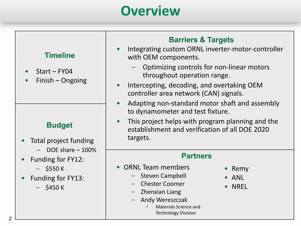
Overview
• Start – FY04 • Finish – Ongoing
• Integrating custom ORNL inverter-motor-controller with OEM components.
– Optimizing controls for non-linear motors throughout operation range.
• Intercepting, decoding, and overtaking OEM controller area network (CAN) signals.
• Adapting non-standard motor shaft and assembly to dynamometer and test fixture.
• This project helps with program planning and the establishment and verification of all DOE 2020 targets.
• Total project funding – DOE share – 100%
• Funding for FY12: – $550 K
• Funding for FY13: – $450 K
Timeline
Budget
Barriers & Targets
Partners • Remy • ANL • NREL
• ORNL Team members – Steven Campbell – Chester Coomer – Zhenxian Liang – Andy Wereszczak
• Materials Science and Technology Division

3 3
Project Objectives/Relevance • Overall Objective: The core function of this project is to observe and define the
current state-of-the-art of EV/HEV technologies. – Assess design, packaging, and fabrication innovations during teardown of sub-systems
• Identify manufacturer techniques employed to improve specific power and/or power density • Perform compositional analysis of key components
– Facilitates trade-off comparisons (e.g. magnet strength vs coercivity) and general cost analysis
– Examine performance and operational characteristics during comprehensive test-cell evaluations • Establish realistic peak power rating (18 seconds) • Identify detailed information regarding time-dependent and condition-dependent operation
– Compile information from evaluations and assessments • Identify new areas of interest • Evaluate advantages and disadvantages of design evolutions • Compare results with other EV/HEV technologies and DOE targets
• Objectives (March 2012 through March 2013): – Complete design/packaging assessments and operational characteristics/performance
evaluations of 2012 Nissan LEAF® inverter/motor and 2012 Hyundai Sonata inverter/hybrid starter-generator (HSG)

4 4
Milestones
Date Milestones and Go/No-Go Decisions Status
September 2012
Milestone:
Complete 2012 Hyundai Sonata inverter/HSG testing. Complete.
September 2012
Go/No-Go decision:
Determine if commercially available EV/HEV system is available and relevant to DOE’s VTO mission.
Go.
September 2013
Milestone:
Complete 2012 Nissan LEAF on-board-charger (OBC) design and packaging assessments.
On Track.
September 2013
Go/No-Go decision:
Determine if commercially available EV/HEV system is available and relevant to DOE’s VTO mission.

5 5
Approach/Strategy
Select subsystem(s)
Disassemble components
Prepare components
Determine volume, weight,
SP and PD
Assess design-packaging
improvements
Design, fabricate, and
instrument
Develop interface &
control algorithm
Test systems for performance, efficiency, and
continuous operation

6 6
Overall Technical Accomplishments
• Prepared detailed comparisons of progressing technologies – 2004 Prius, 2006 Accord, 2007 Camry, 2008 Lexus LS 600h, 2010 Prius, 2011 Hyundai
Sonata motor, 2012 Nissan LEAF, 2012 Hyundai Sonata HSG – Note: Power density and specific power levels in table are not apples-to-apples since
LEAF and Sonata have continuous capability near their published rated power
2020 DOE Targets
2012 Leaf (80 kW)
2012 Sonata
HSG 23 (8.5 kW)
2011 Sonata (30 kW)
2010 Prius
(60 kW)
2008 LS600h Lexus
(110 kW)
2007 Camry
(70 kW)
2006 Honda Accord (12 kW)
2004 Prius
(50 kW)
Peak pow er density, kW/L 5.7 4.2 7.42 (2.7) 3.0 4.8 6.6 5.9 1.5 3.3
Peak specif ic pow er, kW/kg 1.6 1.4 1.9 (0.7) 1.1 1.6 2.5 1.7 0.5 1.1
Peak pow er density, kW/L 13.4 5.7 5.6 (2.0) 7.3 5.9 (11.1) 10.6 (17.2) 7.4 (11.7) 2.9 4.5 (7.4)
Peak specif ic pow er, kW/kg 14.1 4.9 5.4 (2.0) 6.9 6.9 (16.7) 7.7 (14.9) 5.0 (9.3) 2.4 3.8 (6.2)
Component & Parameter
Inverter
Motor
Excludes generator inverter (parenthetical values exclude boost converter mass/volume for Toyota Vehicles)

7
Technical Accomplishments (1)
• Comparison of power converter unit (PCU) and inverter assemblies
– Note: LEAF inverter assembly has only 1 inverter (no generator inverter, boost, or 12 V accessory converter)
– LEAF sized for EV/continuous duty
~15.6 L, ~14.0 L without void space below lid
2012 Leaf

8
Technical Accomplishments (2)
• LEAF Control board includes – Voltage regulation for control and driver
circuitry – Tamagawa AU6803 resolver chip – Renesas R5F71476FPV 32-bit microcomputer
• 512 kB ROM, 16 kB RAM
• DC link parasitics – 600V, 1186.5 µF capacitor (~1.45L)
• SH Film capacitor by Panasonic
• Integrated thermistor • Small 600V, 1.13 µF capacitor
– 15 Watt, 61 kΩ bleed resistor
• Large conductors – DC: ~1/0 AWG – AC: ~3/0 AWG
• Three current transducers integrated with AC bus bars
– 1 Hall effect sensor each – Toyota has 2 CTs with 2 Hall effect sensors
• Driver board – On-chip diode for crude temperature sensing – Lower switches powered with same supply
AC bus bars with CTs
DC bus bars infrastructure
Thermistor
Capacitor X-ray
Terminals Small cap
9
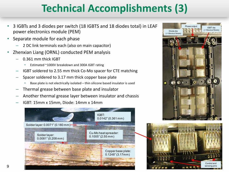
Technical Accomplishments (3) • 3 IGBTs and 3 diodes per switch (18 IGBTS and 18 diodes total) in LEAF
power electronics module (PEM) • Separate module for each phase
– 2 DC link terminals each (also on main capacitor) • Zhenxian Liang (ORNL) conducted PEM analysis
– 0.361 mm thick IGBT • Estimated ~1000V breakdown and 300A IGBT rating
– IGBT soldered to 2.55 mm thick Co-Mo spacer for CTE matching – Spacer soldered to 3.17 mm thick copper base plate
• Base plate is not electrically isolated – thin silicone based insulator is used
– Thermal grease between base plate and insulator – Another thermal grease layer between insulator and chassis – IGBT: 15mm x 15mm, Diode: 14mm x 14mm
Copper base plate:0.1248” (3.17mm)
Solder layer:0.0081” (0.208 mm)
Cu-Mo heat spreader:0.1005” (2.55 mm)
IGBT:0.0142” (0.361 mm)
Solder layer: 0.0071” (0.180 mm)
Control and sensing pins
IGBT die (~15mmx15mm)
Phase output
Diode die (~14mmx14mm)
10 10
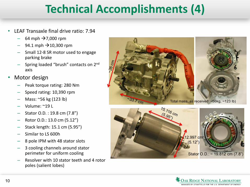
Technical Accomplishments (4)
• LEAF Transaxle final drive ratio: 7.94 – 64 mph 7,000 rpm – 94.1 mph 10,300 rpm – Small 12-8 SR motor used to engage
parking brake – Spring loaded “brush” contacts on 2nd
axis
• Motor design – Peak torque rating: 280 Nm – Speed rating: 10,390 rpm – Mass: ~56 kg (123 lb) – Volume: ~19 L – Stator O.D. : 19.8 cm (7.8”) – Rotor O.D.: 13.0 cm (5.12”) – Stack length: 15.1 cm (5.95”) – Similar to LS 600h – 8 pole IPM with 48 stator slots – 3 cooling channels around stator
perimeter for uniform cooling – Resolver with 10 stator teeth and 4 rotor
poles (salient lobes)
Total mass, as received: ~56kg, ~123 lb)
12.997 cm(5.12”)
Stator O.D.: ~ 19.812 cm (7.8”)

11
Technical Accomplishments (5)
• Published LEAF ratings verified (280 Nm and 80 kW)
– Actually operated above 80 kW
• Tests conditions – DC-link voltage of 375 V – fsw = 5 kHz – Water-Ethylene Glycol temperature:
65C
• Peak motor efficiency above 97% between 5,000 rpm and 9,000 rpm
– Significant region above 90%
• Inverter efficiency above 99% for high speeds
• Stator laminations: – 0.3 mm (0.012”) thick
LEAF inverter efficiency contours
LEAF motor efficiency contours

12
Technical Accomplishments (6)
• Combined LEAF inverter/motor efficiency reached above 96%
– General agreement with published efficiencies
– ORNL measurements slightly higher
• Wide operation range above 90%
• Capable of operating at 80 kW continuously at 7,000 rpm with stator temperatures leveling out at about 135 C
LEAF motor & inverter efficiency contours
50 kW for 1 hour
60 kW for 0.5 hour
70 kW for 0.5 hour
80 kW for 1 hour
LEAF system efficiency published by Nissan
“Power from Within”, Nissan LEAF Special Edition of SAE Vehicle Electrification, p. 17, Feb. 23, 2011.

13
Technical Accomplishments (7)
• Hybrid Starter Generator (HSG) – Published specifications: 43 Nm, 8.5 kW, 15,750 rpm – 3-phase, 36 slot, 6-pole IPM machine – Cold start, restart, and generates when low SOC – Separate low-temperature coolant loop for HSG and
HPCU – Drives and is driven by engine belt (crankshaft) – Roughly same size as alternator
~12 kg, 3.1 L
HSG Stator: 5.1 kg
HSG Rotor: 2.0 kg

14
Technical Accomplishments (8)
• Reached above 20 kW operation
• HSG efficiency (including belt losses) – Peak: 88%, 84% with 8.5 kW operation limit
– Belt losses
• HSG Inverter efficiency – Peak: 98%
• System (HSG & inverter) efficiency – Peak: 87%, 82% with 8.5 kW operation limit
15
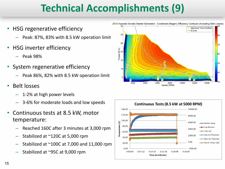
Technical Accomplishments (9)
• HSG regenerative efficiency – Peak: 87%, 83% with 8.5 kW operation limit
• HSG inverter efficiency – Peak 98%
• System regenerative efficiency – Peak 86%, 82% with 8.5 kW operation limit
• Belt losses – 1-2% at high power levels – 3-6% for moderate loads and low speeds
• Continuous tests at 8.5 kW, motor temperature:
– Reached 160C after 3 minutes at 3,000 rpm – Stabilized at ~120C at 5,000 rpm
– Stabilized at ~100C at 7,000 and 11,000 rpm – Stabilized at ~95C at 9,000 rpm

16
Technical Accomplishments (10) • 2013 LEAF On-board charger assessments underway
– Up to 6.6 kW (Separate DC-DC junction box for quick ~50 kW charging) – 120 VAC or 240VAC input
LEAF charger assembly
Cast aluminum water-ethylene-glycol coolant channels
Controls/communication
Isolation

17
Technical Accomplishments (11) • 2013 LEAF On-board charger
– Control board, driver/power board, and capacitor by Nichicon
Filter Inductors
Electrolytic Capacitor (420 V, 2,700 µF)
Electronics module (includes rectifiers, inverters)
Driver-Power Board

18
Water ethylene-
glycol
Technical Accomplishments (12) • 2013 Camry Inverter
– Includes 12V buck converter – IGBT/diode packaging with
two-sided cooling – Similar to Lexus LS 600h – Reduction of 6 IGBTs and
diodes from previous Camry
Motor-generator outputs
IGBT-diode packaging (24 total – 6 generator inverter, 12 motor inverter,
6 boost converter Compact driver board

19 19
Collaborations and Coordination
Organization Type of Collaboration/Coordination
Remy • Providing induction machines for comparisons (copper versus aluminum rotor bars).
ANL
• Provides system parameters to ORNL from on-the-road tests – Includes extreme hot/cold temperature tests
• Examples: – Coolant temperature range and common operation conditions – Battery voltage range and common operation conditions
• ORNL provides component efficiency and operational characteristics for AUTONOMIE
– Also provides to EPA, automotive manufacturers, and public
NREL • ORNL provides component efficiency and operational characteristics to NREL for thermal studies.
20
Future Work
• Remainder of FY13 – Comparison tests on Remy induction motors: copper versus
aluminum rotor bars. – LEAF on-board charger tests and design/packaging assessments. – Camry inverter packaging. – Identify candidate commercially available EV/HEV systems
available and relevant to DOE’s VTO mission.
• FY14 – Select commercially available EV/HEV system relevant to DOE’s
VTO mission. Candidates include: • 2014 Camry inverter/motor. • 2014 Honda Insight. • Remy interior permanent magnet motor.
– Perform standard benchmarking of selected system.

21 21
Summary
• Relevance: The core function of this project is to observe and define the current state-of-the-art of EV/HEV technologies.
• Approach: The approach is to select leading EV/HEV technologies, disassemble them for design/packaging assessments, and test them over entire operation region.
• Collaborations: Interactions are ongoing with other national laboratories, industry, and other government agencies.
• Technical Accomplishments: Tested and reported on more than eight EV/HEV systems including recent efforts on the 2012 Nissan LEAF inverter, motor, and 2013 charger.
• Future work: FY13 efforts are on track, and FY14 plans are in place.