
I. ROGACHEVSKII, N. KLEEORIN, E. LIVERTS Ben-Gurion University of the Negev, Beer Sheva, ISRAEL

Ben-Gurion University of the Negev,Department of Mathematics & Computer Science
BOOMSBooms Object Oriented Music System
Thesis submitted as part of the requirements for the
M.Sc. degree of Ben-Gurion University of the Negev
by
Eli Barzilay:
⋆ Maze is Life! ⋆
The research work for this thesis has been carried out at
Ben-Gurion University of the Negev,
under the direction of Dr. Mira Balaban
December 17 1996

ii
This is the standard place to thank my wife, and apologize for making her life such a mess. I’m noexception: I thank Regina for being. Infinity should be her reward:
λx.xx
Many more Thank instances should be allocated all around. Many of them will remain implicit, but threeshould become explicit:
• Mira Balaban my advisor, for many sleepless nights, good intensions and a strong sense of ontology.
• Michael Elhadad, who sent many useful messages and provided callbacks.
• My mother and father for making me who I am. Non of this could happen without their motivation,implementation and maintenance.
A word on sexist language: I know that referring to the ‘user’ as a male user is not “politically correct”.My native language is Hebrew, which is sexist by default (using male as default). English is a bit better(like the word “user” having no sex), but still, there is no sex-less form for ‘he’, ‘his’ etc. I’ve decidedagainst using long combinations like ‘his/hers’ or the provocatively distractive form ‘hers’ — I simply usemale as default. The intelligent reader can transform all these to female form if he (she!) wishes.
Have lots of fun,Eli Barzilay:
Maze is Life!

ii

Abstract
This work addresses the problem of providing a computer-based environmentto support the music composition process. One of the prominent aspects ofthe composition process is the importance of structure: for a composer, amusic piece is more than its flat score; it is a structured object, and itsstructure captures the expressive intention of the composer.
Existing music editors do not provide appropriate support for compo-sition: most only address the score editing process, but more profoundly,because there is no uniform or conventional way to denote structure in musicpieces, it has been unclear what information a structural editor for musicshould manipulate. Given this state of affair, composers must remember oradd personal annotations to their compositions to remember their structure.As a result, the editor cannot provide support for the manipulation of themusic piece as a structured and meaningful object.
This thesis presents the BOOMS editor intended for music composition.BOOMS supports a combination of structural and non-structural editingof music pieces and demonstrates the added power provided by an explicitrepresentation of structure. The main focus of the work has been on:
• Developing a methodology to combine structural editing in non-structuraleditors;
• Investigating how abstraction mechanisms can help to turn an editingsession into a reusable function, which captures the intention of thecomposer;
• Formally comparing direct abstraction on the music pieces being editedand abstraction on the history of the commands the composer used tobuild a piece.
The BOOMS system was developed as a general application framework fordeveloping editors with support for a combination of structural and regularediting and support for end-user abstraction as a tool to define reusablefunctions without programming. The framework is implemented in CLOS(the Common Lisp Object System) and features a sophisticated Windowsinterface. Instantiating the framework to a specific editing domain is a simpletask, due to the clean object-oriented design of the framework.
While the BOOMS framework is generic, it is most effective when instan-tiated to domains similar to music composition, where a user incrementally
ii
builds a structured object by using a restricted set of commands to combinesmaller units into larger ones. The BOOMS framework was instantiated tothree domains to illustrate the support an abstraction-enabled structural ed-itor can provide to end users: music composition, arithmetic expressions andediting in a micro-world of colored cubes (GCalc).
In a BOOMS instantiated editor, the end-user interacts with the actualpiece being created using simple editor commands. At the same time, a viewof the editing session (as an editing graph) is maintained by the editor. Theediting graph can be edited by the user to specify his intentions. Abstractioncan also be performed on the editing graph, turning a sequence of editingoperations into a new reusable function, that can be used either in the simpleeditor view or in the structural editing graph view.
A feature of the BOOMS framework is that it defines a place wheredomain-specific knowledge can be introduced in an editor: the node con-structors for the domain and the operators for each type in the domain canbe encapsulated in well-defined domain libraries and easily integrated in theBOOMS framework. In particular, the BOOMS music domain editor in-corporates well-defined knowledge of music notes, intervals, and arithmeticsover them. It is a promising area of future work to extend this package to amore comprehensive music knowledge base.

Contents
1 Introduction 11.1 The Hierarchy Aspect in Music . . . . . . . . . . . . . . . . . 21.2 Introducing “BOOMS” . . . . . . . . . . . . . . . . . . . . . . 31.3 Thesis Plan . . . . . . . . . . . . . . . . . . . . . . . . . . . . 4
2 Related Work 72.1 Computer Music Environments . . . . . . . . . . . . . . . . . 72.2 Historical Editing and Structural Editing . . . . . . . . . . . . 92.3 Abstraction and End-user Programmability . . . . . . . . . . 12
3 Hierarchical Editing — BOOMS 133.1 Editing as a Structured Process . . . . . . . . . . . . . . . . . 133.2 Editing Graphs are Intensional . . . . . . . . . . . . . . . . . . 14
3.2.1 Intensionality and Hierarchy Editing . . . . . . . . . . 153.2.2 Formal Description . . . . . . . . . . . . . . . . . . . . 15
3.3 Editing Graph and Destructive Operations . . . . . . . . . . . 163.3.1 Example: Usage Scenario . . . . . . . . . . . . . . . . . 173.3.2 Constructive Editing . . . . . . . . . . . . . . . . . . . 18
3.4 Conclusion: Historical Editing . . . . . . . . . . . . . . . . . . 18
4 BOOMS on Different Domains 214.1 GCalc Domain Description . . . . . . . . . . . . . . . . . . . . 244.2 The GCalc Flat-Form Editor . . . . . . . . . . . . . . . . . . . 254.3 GCalc’s Formals, Part I: COLORS . . . . . . . . . . . . . . . 31
4.3.1 Values . . . . . . . . . . . . . . . . . . . . . . . . . . . 314.3.2 Selectors . . . . . . . . . . . . . . . . . . . . . . . . . . 324.3.3 Similarity . . . . . . . . . . . . . . . . . . . . . . . . . 334.3.4 Syntax . . . . . . . . . . . . . . . . . . . . . . . . . . . 34
iii

iv CONTENTS
4.4 Implementing GCalc in BOOMS . . . . . . . . . . . . . . . . . 35
4.4.1 Session Sample . . . . . . . . . . . . . . . . . . . . . . 36
5 Abstractions 39
5.1 Introducing Abstraction & Application . . . . . . . . . . . . . 39
5.1.1 The Power of Abstraction . . . . . . . . . . . . . . . . 40
5.2 Flat-Form Abstractions . . . . . . . . . . . . . . . . . . . . . . 40
5.2.1 GCalc’s Formals, Part II: FCOLORS . . . . . . . . . . 42
5.2.1.1 Values . . . . . . . . . . . . . . . . . . . . . . 42
5.2.1.2 Selectors . . . . . . . . . . . . . . . . . . . . . 43
5.2.1.3 User Ontology Functions . . . . . . . . . . . . 43
5.2.1.4 Auxiliary Functions . . . . . . . . . . . . . . 44
5.2.1.5 Similarity . . . . . . . . . . . . . . . . . . . . 47
5.2.1.6 Syntax . . . . . . . . . . . . . . . . . . . . . . 48
5.2.2 Generalizing GCalc’s Abstractions . . . . . . . . . . . . 48
5.2.3 GCalc’s Formals, Part III: GCALC . . . . . . . . . . . 49
5.2.3.1 Selectors . . . . . . . . . . . . . . . . . . . . . 49
5.2.3.2 Functions . . . . . . . . . . . . . . . . . . . . 50
5.2.4 Session Sample . . . . . . . . . . . . . . . . . . . . . . 52
5.2.5 Flat-Form Abstractions in BOOMS . . . . . . . . . . . 55
5.3 Structure Abstractions . . . . . . . . . . . . . . . . . . . . . . 55
5.3.1 Structure Abstraction in BOOMS . . . . . . . . . . . . 56
5.3.2 Hiding Details . . . . . . . . . . . . . . . . . . . . . . . 57
5.3.3 Session Sample . . . . . . . . . . . . . . . . . . . . . . 59
6 System Outline 61
6.1 Nodes . . . . . . . . . . . . . . . . . . . . . . . . . . . . . . . 61
6.2 Document Types . . . . . . . . . . . . . . . . . . . . . . . . . 64
6.3 Multiple View Editing . . . . . . . . . . . . . . . . . . . . . . 65
6.4 Miscellaneous . . . . . . . . . . . . . . . . . . . . . . . . . . . 67
6.5 User Interface Considerations . . . . . . . . . . . . . . . . . . 68
6.5.1 Expectations Detection . . . . . . . . . . . . . . . . . . 68
6.5.2 GUI Usage . . . . . . . . . . . . . . . . . . . . . . . . . 69
6.5.3 Visualization Considerations . . . . . . . . . . . . . . . 72
6.6 Program Interface Considerations . . . . . . . . . . . . . . . . 73
6.6.1 Advanced Programming Language . . . . . . . . . . . 74
6.6.2 Technicalities . . . . . . . . . . . . . . . . . . . . . . . 75

CONTENTS v
7 Conclusion 797.1 Future Music editing Development . . . . . . . . . . . . . . . 80
A BOOMS Users Manual 83A.1 Platform . . . . . . . . . . . . . . . . . . . . . . . . . . . . . . 83A.2 Getting BOOMS . . . . . . . . . . . . . . . . . . . . . . . . . 83A.3 BOOMS Loading / Compiling / Running . . . . . . . . . . . . 85A.4 Using BOOMS . . . . . . . . . . . . . . . . . . . . . . . . . . 85
A.4.1 General Hierarchy Editing . . . . . . . . . . . . . . . . 86A.4.2 Document Types . . . . . . . . . . . . . . . . . . . . . 87A.4.3 The Class Palette . . . . . . . . . . . . . . . . . . . . . 89A.4.4 Abstractions . . . . . . . . . . . . . . . . . . . . . . . . 90A.4.5 Menu Commands . . . . . . . . . . . . . . . . . . . . . 91A.4.6 Keyboard / Toolbar Shortcuts . . . . . . . . . . . . . . 95A.4.7 Node Edit Panes . . . . . . . . . . . . . . . . . . . . . 96
B BOOMS Programmers Reference 99B.1 Document Type and Icon Class Additions . . . . . . . . . . . 99B.2 Lisp Code Explanations . . . . . . . . . . . . . . . . . . . . . 99
B.2.1 The Files . . . . . . . . . . . . . . . . . . . . . . . . . 99
C The GCalc Mini System 103C.1 Scheme Implementation . . . . . . . . . . . . . . . . . . . . . 103C.2 FTPing, Extracting, Running . . . . . . . . . . . . . . . . . . 103C.3 System Documentation . . . . . . . . . . . . . . . . . . . . . . 104
C.3.1 General Description . . . . . . . . . . . . . . . . . . . . 104C.3.2 Functional World . . . . . . . . . . . . . . . . . . . . . 104C.3.3 Visualization . . . . . . . . . . . . . . . . . . . . . . . 105C.3.4 System Description . . . . . . . . . . . . . . . . . . . . 106C.3.5 Building Expressions . . . . . . . . . . . . . . . . . . . 107C.3.6 The Evaluation Model . . . . . . . . . . . . . . . . . . 108C.3.7 Reduction Rules . . . . . . . . . . . . . . . . . . . . . 109C.3.8 Functional Extensions . . . . . . . . . . . . . . . . . . 111C.3.9 Formal Definition of GCalc . . . . . . . . . . . . . . . 112
Bibliography 115

vi CONTENTS

Chapter 1
Introduction
This work deals with the problems arising when developing computer musicenvironments to support music composition. It investigates the general issuesof hierarchical editing and abstraction as an end-user programming techniquewithin the context of a music editor.
The main motivation of the work is that existing music editors are too lim-ited in scope and functionality to effectively support the composition process.The limits derive from two factors: (1) Most music editors so far have beenrestricted to score editing and therefore only the result of the compositionprocess is stored and represented, but the structure of the piece, the historyof its creation and its motivation is lost. (2) No conventional notation hasbeen accepted within the music community to denote the structure of musicpieces. The only “universal” notation for music is the flat score encoded inthe common music notation. Therefore there is no accepted way to make-upfor the lack of structure support in a score editor by adding mark-up tagswithin the flat score, as is done in text editors.
Accordingly, the objective of this work is to provide a notation to encodestructure in music pieces that can be easily used in a direct-manipulationeditor. With this objective, the work has evolved into a general investigationof hierarchical editing and the services a hierarchical editor can provide.
The contributions of the thesis are the development of an applicationframework for hierarchical editors (the BOOMS system), the definition of ageneral methodology to combine a domain specific editor with hierarchicalediting (through the notion of editing graphs and historical editing) and thestudy of how hierarchical editing facilitates end-user programming throughthe use of abstraction on editing graphs.
1

2 CHAPTER 1. INTRODUCTION
This generic framework has been applied to create an innovative musiceditor combining hierarchical and flat-form editing and supporting an in-tuitive form of abstraction definition. The prototype editor is a promisingplatform to investigate ways to introduce rich music knowledge within musiceditors.
1.1 The Hierarchy Aspect in Music
Hierarchical structuring is inherent to music conception. As an acoustic phe-nomenon, music is a stream of sounds, but it is never conceived as such.Hierarchy is central to any music activity — listening, analysis, composition,tutoring, performance, typesetting and computer processing. In listening,the natural structuring performed in the listener’s mind, plays a major rolein the generation of music expectations [1]. In analysis, a major subject in-volves structuring of a music piece along multiple dimensions and analyzingthe inter-relationships between such simultaneous structurings in harmony,rhythm, melody and dynamics [2, 3, 4, 5]. In composition, hierarchy has amajor role in the actual construction of a piece: abstraction and generaliza-tion in the bottom-up direction, and instantiation in the top-down directionare essential composition approaches [6].
The need for hierarchy and structuring in the design and application ofcomputer music tools is intimately interlaced in the short history of computermusic [7, 8, 9, 10, 11, 12, 13, 14, 15]. Typesetting has a hierarchical aspectas well [16]. In the design of low level protocols like MIDI [17] and Zippy [18]the need for structure is frequently mentioned.
The work on Music Structures that motivated the BOOMS project con-centrates on characterization of the ontology of structured music pieces as asemantic domain for a computer music environment. It suggests the view ofa music piece as a temporal structure whose components are nested temporalstructures — SMP (Structured Music Piece). The hierarchical constructionstarts from some primitive layer, that includes sounds (defined by attributessuch as pitch or timbre) or atomic motives. The multiple structuring of asingle piece gives rise to multiple SMPs, all sharing a single flat music piece
that acts as their extensional normal form.
The structure of an SMP can be syntactically specified by various con-struction operators. The basic [direct] operator is general music-concatenation,

1.2. INTRODUCING “BOOMS” 3
denoted “@”. The expression
@(MP0, t,MP)
denotes the extension of the music piece denoted by MP, with MP0, playedat time t, relative to MP’s beginning. Two useful special case operators aresimultaneous and sequential concatenations, which are roughly definedas:
Simultaneous: A | B = @(B, start(A), A)
Sequential: A − B = @(B, end(A), A)
Examples of other useful operators are transpose, reverse, stretch, andmerge.
In a Computer Music Environment based on the Music Structures view,the operators are the construction means (value constructors). They expressthe compositional intention of the user. Hence, the history of an editing ses-sion evaluates to the intended composition, and provides the logical structureof the composition.
1.2 Introducing “BOOMS”
BOOMS is a generic framework to study and develop sophisticated domain-specific editors. The project is motivated by Computer-Music Environmentneeds. The eventual goal of the project is to develop a music workstation sup-porting multiple structured representations for a single music piece, followingthe Music Structures representation of [12]. This has led to the developmentof a hierarchical editor, that manipulates hierarchical music structures ratherthan the flat music score: the first stage of BOOMS Object Oriented MusicStructures (abbreviated BOOMS).
The hierarchical structures in BOOMS are represented by an internalDAG (Directed Acyclic Graph) data structure that contains node objects.Leaves in this hierarchy stand for “atomic” music pieces (usually singlenotes), and internal nodes are music constructors. Playing a piece amountsto evaluating the structured hierarchy (the DAG) — calculating a flat valuewhich is the normal form of the structured music piece. All structured viewsof a music piece share the same flat normal form (i.e., they sound identical).

4 CHAPTER 1. INTRODUCTION
The hierarchical representation stands for the composer’s intentions, anddefines an ontological object (an actual music piece) implicitly: evaluationmust be used to retrieve this extension.
1.3 Thesis Plan
In an effort to uncover the potential of hierarchical editing to end-users, theBOOMS editor was abstracted into a generic application framework for struc-tural editing by untangling the editor part from the specific music knowledge.The resulting framework is described in detail in Chapter6. It includes thefollowing layers:
1. Domain-independent node (constructor) management: the Node class.These nodes compose the internal hierarchy data structure.
2. Graphic editor for hierarchy manipulations: the Icon class. This classaugments the Node class (using inheritance). The user manages objectsof this class that are visualized nodes.
3. On top of these two general layers, a package mechanism layer supportsimplementation of multiple domains. This way, BOOMS can be usedfor diverse hierarchical domains.
Three specific domains are implemented — a music domain, a coloredcubes graphical domain and an arithmetic domain.
A contribution of the work is the definition of a general methodology toturn a domain-specific editor into a combined hierarchical-direct editor. Theapproach is based on the view that each command performed by the userin the native editor on domain values is recorded in an editing graph. Inthe editing graph, each node corresponds to a user command and combinesdomain values (the parameters of the command) into new complex values.As the editing graph evolves, every argument is itself a node in the previousstate of the editing graph. The editing graph therefore encodes the historyof an editing session. This methodology is introduced in Chapter 3.
In structured domains like music composition, the editing graph corre-sponds to the structure of the music piece being constructed. But becausethe editing process can evolve in random ways, the editing graph can de-velop into a tangled web. Because the structure of the music piece is of

1.3. THESIS PLAN 5
importance to the user (it captures his intention), the BOOMS approach al-lows the composer to directly edit the graph. The BOOMS framework thusfulfills two needs: it implicitly defines a language to describe the structure ofa music piece by mapping editor commands to structural constructors, andit provides a direct manipulation tool for the resulting structural objects.This is particularly important for music composition, because there is noconventional way to denote structure for music pieces. The application ofthe BOOMS methodology to different domains is discussed in Chapter 4.
In addition, the BOOMS editing approach, through the reification ofthe editing process, allows non-programmers to turn editing sessions intonew operators. Because editing actions have been turned into objects (theediting graph), it becomes natural to abstract a subgraph of the editing graphinto a new node constructor. This is an intuitive way to create user-definedfunctions. This work presents an in-depth investigation of the abstractionprocess enabling such definitions, and compares it with direct abstraction ondomain values which was proposed as an alternative technique for end-userprogramming in [19]. This is discussed in Chapter 5.

6 CHAPTER 1. INTRODUCTION

Chapter 2
Related Work
This work builds on different disciplines and fields. The main topics ad-dressed are: computer music environments and composition environments;the general editing process; abstraction and end-user programmability.
2.1 Computer Music Environments
In this section we investigate two music environment applications that areboth advanced and widely used: DMIX and Common Music.
DMIX
DMIX [13] is a system written by Danny Oppenheim in Smalltalk. The mainconcept of DMIX is an expressive user-interface which operates in multipledimensions, including many visualization forms like box-graph, score, andtext representation. DMIX entails an extensive set of functions, some ofthem are used via “slapping” — dragging one music piece and dropping onanother, performing some interaction between both.
The combination of multi-dimensional representation with slapping allowsfor an interesting form of abstraction in the following way: a view can rep-resent the pitch of a music piece, another view the rhythm of another piece;by slapping (dropping) the pitch view on the rhythm view, one can obtain anew music piece composed of these pitch and rhythm specifications. In thisoperation, the rhythm dimension of the second piece has been abstractedinto a function that has been applied to the first piece.
7

8 CHAPTER 2. RELATED WORK
Although very impressive, DMIX has some disadvantages. First of all,there is no formal model for DMIX. It was developed as a private tool by onemusician, and extended over time to a full application. Comparing DMIXwith BOOMS reveals two additional points where BOOMS provides featuresthat are necessary in such music environments:
• There is no hierarchy information in any form (applying an operation ona music piece yields a new one that has no connection to the original).
• Abstraction is limited to slappability, i.e., one can only abstract a sin-gle dimension for which a view already exists in the system — newviews cannot be created by end-users, and slappable views cannot becombined. End-user programmability or extensibility is therefore im-possible.
Common Music
Common Music [20] is a Common Lisp-based system written by Rick Taube.Comparing Common music to other computer-music tools is similar to com-paring Common Lisp to other programming languages. Common Music pro-vides a very rich set of of music primitives and types to support algorithmiccomposition. Many useful features are implemented like streams, containersand algorithmic music.
Compared to other computer-music applications, Common Music is moreprogrammer-oriented than most applications, however, it is attractive enoughto make musicians learn how to use it (a surprising point is that musiciansactually spend time to learn how infinite streams are used). The containersfeature of Common Music supports hierarchy in compositions, however, thisis similar to nested procedures: the non-trivial management of containers andthe overhead involved prevents using this feature for constructing music likenodes are used in BOOMS (no Common Music user will ever use a containerfor three notes).
Common Music is very close to Common Lisp, so features like abstractionsare handled using Lisp. Another effect of this is the system being verycomplex, for example, many macros are used all over (working without thereference manual is an impossible task for many users). This approach makesthe usage of advanced features like abstractions not applicable for noviceusers. There is a graphical user interface implemented (Stella), but it is onlypartial in the sense that many features are not accessible through it.

2.2. HISTORICAL EDITING AND STRUCTURAL EDITING 9
The Common Music system demonstrates the need for programmabilityin composition environments. One of the most interesting features of thesystem is the pervasive use of streams. BOOMS is different from CommonMusic by emphasizing hierarchical structure usage and making abstractionan intuitive mechanism to support end-user programmability.
2.2 Historical Editing and Structural Editing
The Programmer’s Apprentice
The objective of the Programmer’s Apprentice project [21] is to study howa knowledge-based editor can help automate the tasks of program writing,modification and documentation. One of the main themes of the research isthat the editor must encode explicitly more information than is written inthe text of the program in order to appropriately assist the programmer. Inthe KBEmacs prototype, this additional knowledge is encoded in the formof cliches. A cliche encodes the knowledge shared by the programmer andan external assistant when modifying a piece of code. The following exampleshows a cliche defined for enumerating a Lisp list:
(DEFINE-PLAN CDR-ENUMERATION
(PRIMARY-ROLES (LIST)
DESCRIBED-ROLES (LIST)
COMMENT "enumerates the elements of {the list}")
(LET* ((LIST {the input list}))
(LOOP
(IF ({NULL, the empty} LIST) (RETURN))
{({CAR, the current} LIST), the output element}
(SETQ LIST ({CDR, the rest} LIST)))))
Definitions of cliches include a body over which parameters are abstractedand, most importantly, a set of annotations that explicitly describe the rolesof parameters and constraints over their instantiation. In the above exam-ple, the methods to test if a generalized list is empty is abstracted to theannotation {NULL, the empty}, comment annotations are also introducedwhich are later used to automatically generate documentation for the code.Other annotations can be used to introduce constraints on parameters.
This knowledge is used by the editor to provide the following function-ality: during program synthesis, the programmer can select a cliche from

10 CHAPTER 2. RELATED WORK
a library and instantiate it using explicit editor commands. The program-mer can alternatively enter code directly and an analyzer parses the code torecognize instances of existing cliches. In both cases, the editor maintainsan explicit representation of the cliche structure of the code — called theprogram plan — in addition to the program text. Because the program planis explicitly maintained, the KBEmacs editor can support modification ofthe program at a much higher level of abstraction than a character basededitor can. Beyond parse tree editing (as provided by syntactic editors),KBEmacs claims to support editing at the level of “algorithmic structure”.This translates into sophisticated support for program modification: if aprogrammer decides to switch a CDR-enumeration through a list into anARRAY-enumeration, the editor can transpose automatically the instancesof the CDR-enumeration, and propagate this change to all relevant occur-rences.
The Programmer’s Apprentice project illustrates the need to maintain ex-tra information in addition to the flat domain values being edited, to describethe intention of the designer. The need for such meta-editing knowledge ismade even more pressing in the domain of music composition, because of thelack of established mark-up standards in music notation.
In KBEmacs, the integration of the domain value editing and knowledgeediting is through a stage of automatic analysis and plan recognition of theuser actions. While this approach is conceivable in the programming domain,where a large cliche library can be designed building on extensive results insoftware engineering and programming language semantics, it is much harderto apply in the music domain, where even a notation for structure is missing,and the notion of “composer intention” is much harder to grasp. In addition,music creators often consciously seek ambiguity in their composition, and aplan recognition mechanism would perform poorly in such conditions.
The alternative approach implemented in BOOMS, is to provide explicitediting of the editing graph, to empower the composer with the possibilityto specify his intention. Automatic analysis of the editing actions is beyondthe scope of this work.
Besides this difference, in BOOMS as in KBEmacs, the ideal place tointroduce domain specific knowledge to introduce sophisticated services inthe editor is in the set of editor commands. The BOOMS music knowledgebase is encapsulated in a library of editor commands, appearing to the userin a palette, and plays a role parallel to KBEmacs’s cliche library.

2.2. HISTORICAL EDITING AND STRUCTURAL EDITING 11
Chimera
In the Chimera graphical editor [22], Kurlander investigated ways to auto-mate repetitive tasks in user interfaces. The Chimera system is built usingdemonstrational techniques — empowering users to “program an applicationthrough its user interface.” Kurlander developed five powerful techniquesto automate repetitions. Most relevant to this work are the techniques ofeditable graphical histories and macros by example built on top of them.
Graphical histories encode in a comic strip metaphor the commands usedin an editing session: “Commands are distributed over a set of panels thatshow the graphical state of the interface changing over time. These historiesuse the same visual language as the interface” ([22, p.11]). The graphicalhistory is automatically maintained as the user performs actions on the edi-tor. Strategies are designed to make histories shorter and focus on significantactions in the system. Declarative rules encoding regular expressions of com-mands are used to analyze the stream of commands issued by the user andcoalesce similar commands into a single pane of the history.
Histories serve as a basis for a sophisticated form of undo-redo wherethe user can select which section in the history to undo or redo, and havethe editor propagate changes through the rest of the session as required. Inaddition, histories are used as the basis for a form of abstraction implementedin the graphical macro by example technique of Chimera. The main conceptis to abstract histories into functions by generalizing some of the objectsmanipulated in a sub-session. The abstracted sub-session is then named andcan be used as a new command.
The BOOMS approach is heavily influenced by Kurlander’s work, in itsfocus over histories (which are called editing graphs above). The main dif-ference in approach is that Chimera depicts histories in the same visual lan-guage as the object editor, while BOOMS depicts them in a hierarchicalview, focusing on their structural properties. The latter approach is a designdecision motivated by the need to denote structure in music composition. InBOOMS, the differences between the properties of the editing graph and thevalues being edited is also investigated formally.

12 CHAPTER 2. RELATED WORK
2.3 Abstraction and End-user Programmabil-
ity
Orlarey and others in [19] propose to build a music calculus based on purelambda calculus. To illustrate the use of abstraction, they develop an editorin a micro-world of colored cubes, that can be combined around the threedimensions. The main idea investigated in their system is to provide the userwith the possibility to abstract over the primitive values being edited. Theresulting domain includes both the colored cube values and the functionsobtained as a result of abstraction.
This system is discussed at length in Chapter 4, where a reimplementa-tion is presented (the GCalc system), together with a formal analysis of thedomain and of the abstraction process. The BOOMS approach mainly differsfrom the GCalc model in that abstracted functions are not part of the valuedomain. This difference is parallel to that with the Chimera system — inBOOMS, both editing graphs and abstracted functions are objects that thecomposer wants to represent and manipulate. The BOOMS hierarchical viewprovides a language to denote structure when no such formalism is generallyavailable in music.

Chapter 3
Hierarchical Editing —BOOMS
In this chapter we introduce the notion of hierarchical and historical editing.We show that editing sessions themselves, can be characterized as structuredexpressions. Hierarchical editing is the manipulation of such structured ex-pressions. It is contrasted to flat-form editing, where the result of the editoroperation is always fully evaluated: hierarchical editing is intensional, whileflat-form editing is extensional. At last, we introduce historical editing, asa dual editing mode, where the user can manipulate both the flat-form ofhis creation and edit directly the operational hierarchy of his editing ses-sion. BOOMS supports a restricted form of historical editing that we call“Constructive Historical Editing”.
3.1 Editing as a Structured Process
In this section, we develop the view of an editing session as a structuredprocess, represented by some hierarchical expression. This is enabled byviewing an editor as generating a functional domain: an editor is always ina state which is represented by a value (or values), and the user can performoperations which bring the editor to other states. The values representingthe editor state are the functional domain values, and the user-operationsare functions on these values.
A simple example for an editor and a corresponding domain is a pocket-calculator. It has a state which is composed of several number values — at
13

14 CHAPTER 3. HIERARCHICAL EDITING — BOOMS
least two numbers are needed for using the simple binary functions, and thereis usually some kind of a memory storage place. The arithmetic operationsare functions that operate on the calculator’s current values and set newones. These values and the user functions attached to the calculator keyscompose a functional domain.
We proceed to representing an editing session as an expression hierarchy.This is immediate once having a functional representation for an editor do-main, since functional expressions are naturally viewed as trees (e.g., syntaxtrees). Given a set of values V (editor states) and a set of functions F (editoroperations), let H denote the set of hierarchical expressions over 〈V, F 〉. Thevalue of a hierarchical expression is given by a function Eval : H 7→ V thatevaluates expressions in H into the actual values in V — by applying thecorresponding functions in F .
Note that the tree representation of functional expressions is appropriatewhen they are pure values. If hierarchy values are objects (with identity)then the representation uses DAGs (Directed Acyclic Graph).
3.2 Editing Graphs are Intensional
Editing is an operation along time. An editor that keeps track of editingoperations along some period of time, and allow editing of the correspondingoperational hierarchy, is called a Historical Editor. Such an editor generatesa functional term for each operation. These terms preserve the history; theirevaluation yields the intended result. The generation of this hierarchicalexpression is domain-independent. It is natural for a historical editor to havetwo views: one for the original [extensional value] domain and support directmanipulation, and another for the hierarchical expressions that represent theprocesses that created these extensional values.
In this section, we first compare the domain of values manipulated in theflat form editor (the original domain of values) and the values manipulatedin the historical editor. As discussed in Chapter 2, it is often claimed thatthese two domains should be kept as close as possible, to allow the userto manipulate histories in the same way as domain values. We develop aformal analysis of editing graphs to precisely explain how editing graphsdiffer from domain values. In the next section, we analyze a second reasonwhy the domain of editing graphs and the value domain differ: certain editingcommands are destructive, and leave no trace in the value being constructed.

3.2. EDITING GRAPHS ARE INTENSIONAL 15
3.2.1 Intensionality and Hierarchy Editing
The critical difference between domain values and editing graphs is that thelater are intensional. Indeed, a historical editor enables direct manipulationof the operational hierarchy. The BOOMS editor supports graphical DAGsediting. This way, using subexpressions of the final creation is an inherentfeature; logical subunits of our creation can be directly referenced. Anotheradvantage is the support of multiple top-level hierarchies (multiple roots),rather than a single value.
When editing, the handling of objects (values with identity) is more ap-propriate than pure values. That is, object manipulation is descriptivelymore powerful than manipulation of values. For example, the expression“2 × 2” can use two different 2’s, or the same single 2 object. These twooptions represent different intentions — like calculating the area of a 2-by-2rectangle, or the area of a square with an edge length of 2. We also gain thebenefit of better evaluation times, since each node in the graph is evaluatedonly once. This brings us closer to the expression graphs in [23].
In the intensional approach, the hierarchical operation expressions areDAGs: nodes represent operations, and edges represent the relationship of asubexpression node being an argument of a parent expression node. Manipu-lating an acyclic graph rather than a tree means that subexpression-sharingis allowed. Henceforth, the term “historical editing” is always used in itsintensional meaning (manipulation of objects).
3.2.2 Formal Description
To precisely explain the intensional nature of the historical editing domain,we propose a formal description of the process of maintaining the editinggraph over a flat form editor.
The Functional Domain
The functional domain D = 〈V, F 〉 is a pair of the values set, and the func-tions set, as follows:
• V is any set of values.
• F is a set of functions over V :F ⊆ V n 7→ V

16 CHAPTER 3. HIERARCHICAL EDITING — BOOMS
The Hierarchical World
The definition of the hierarchical world W = 〈H,C, Eval〉, based on thefunctional domain D, is a triplet of hierarchical values, constructor functionsand an evaluation function, as follows:
• C has a constructor function f for each domain function f in F (n isused as the function’s arity, f has the same arity):∀f ∈ F : ∃f ∈ C :
f : H 7→ H
∀x1, x2, . . . , xn ∈ H :f(x1, x2, . . . , xn) = X ⇐⇒
X = f(y1, y2, . . . , yn) ∧ x1 = y1 ∧ x2 = y2 ∧ . . . ∧ xn = yn
• H is defined using primitive values V and augmented by the construc-tors in C:
– V ⊆ H
– x1, x2, . . . , xn ∈ H, f ∈ C =⇒ f(x1, x2, . . . , xn) ∈ H
– No other values are in H.
• The Eval function gives the semantic value of the syntax values in H:Eval : H 7→ V
Eval(x) =
x if x ∈ V
f(Eval(x1), Eval(x2), . . . , Eval(xn))
if x = f(x1, x2, . . . , xn), f ∈ C
3.3 The Editing Graph Preserves Destruc-
tive Operations
The general operation set of an editor can be categorized into two classes:
Constructive operations These are the usual operations — operationsthat make us “advance toward the final goal”. Most of the ‘interesting’operations fall in this category, they are ‘interesting’ because they addinformation — they create explicit combinations: applying operator O
on states S1, . . . , Sn is simply O(S1, . . . , Sn) (a construction or a value).
There are many examples for constructive operations, they are usuallydomain dependent because they construct values (or compute a value)

3.3. EDITING GRAPH AND DESTRUCTIVE OPERATIONS 17
specific to the domain of the values they operate on. Text writing /pasting in a text editor and value entering / calculating on a calculatorare constructive operations.
Destructive operations These are operations that make the editor go backto some previous values (or state) like the ‘undo’ operation, or producevalues that are not explicit combinations of previous ones, like the‘delete’ operation.
Note that this usage of the term ‘destructive’ is different from its usein programming languages — changing the internal state of an object.
These operations, contrasted to constructive operations, tend to be do-main independent for reasons explained below. Examples of destructiveoperations are deletion, undoing and resetting.
Surely, constructive operations should be recorded in the historical struc-tures created by the editing session — otherwise we will not be able toremember the way a value was produced.
On the other hand, destructive operations are used to recover previousediting state / values, so we want this feature to be reflected in the corre-sponding hierarchical values created. This means that destructive operationsare not implemented as constructors for hierarchy values, but as functionsthat map hierarchy values to other hierarchy values — these can be consid-ered as meta-level [destructive] operations for hierarchy maintenance.
There can be a situation where the user wants to keep the destructiveoperations in the hierarchy — like when abstracting a sequence of operationsusing their hierarchical form. Think of keyboard-macros in Emacs whichcarry a similar kind of abstraction — it can be the sequence of ‘A’–DEL–‘B’,which is exactly equal to ‘B’ (and the destructive information is redundant),but it can be the sequence DEL–‘A’ where the destructive operation must bepart of the macro.
3.3.1 Example: Usage Scenario
This example demonstrates destructive operations. We use a different editordomain — a text editor. Text is a stream of characters with no structureand the operations used to create it define the operational history structure.The only operations are concR for concatenating on the right, and ConcL on

18 CHAPTER 3. HIERARCHICAL EDITING — BOOMS
the left. The text string ‘ABC’ can be the result of
concR(concR(‘A’, ‘B’), ‘C’)
orconcL(concR(‘B’, ‘C’), ‘A’)
These two options for creating the ‘ABC’ text correspond to two possible waysfor a user to generate this text — typing ‘A’, ‘B’ and ‘C’, or typing ‘B’, ‘C’and then ‘A’ at the beginning.
If this editor allows destructive operations like undo, we can have morehistory expressions that generate this text, like:
concR(undo(concR(concR(‘A’, ‘B’), ‘D’)), ‘C’)
which happens when the user mistakingly enters ‘ABD’, then undoes the ‘D’and finally adds the correct ‘C’.
3.3.2 Constructive Editing
The implementation of selective historical editing by using meta-level oper-ations (partial evaluation of destructive editing operations) for destructiveoperations is called Constructive Editing Approach. For example, in theabove text editor domain, when the user corrects the mistaken ‘D’ charac-ter, we get a corresponding subexpression of the form undo(concR(X,Y )).Such expressions can easily be identified and replaced by their simpler equiv-alent form X — this simpler expression is the result of a meta-level deleteoperation.
If the constructive editing approach is to be implemented in a hierarchicaleditor, then the user should be given a way to say whether he wants suchautomatic reductions or not, as there are cases (mentioned above) where thedestructive information should be kept.
Note: the BOOMS system does not handle editor domains that includedestructive operations. It allows, however, manual meta-level operations likedeletion on hierarchy structures.
3.4 Conclusion: Historical Editing
This chapter has developed a view of editing as a constructive process, wherethe editor automatically maintains an editing graph reflecting the actions

3.4. CONCLUSION: HISTORICAL EDITING 19
performed by the user on a flat form editor. This editing graph can thenbe directly edited by the user. We have precisely highlighted the differencesbetween the domain of values manipulated by the flat form editor and thosemanipulated by the history editor: editing graphs are intensional even whenthe value domain is extensional, and editing graphs record destructive op-erations, and, therefore, dealing with destructive operations in a historicaleditor requires special care.
Hierarchical Editing of the operational history has the following advan-tages:
• Can describe any history of editing, on any editor domain.
As we’ve seen — any editing session can be represented by an opera-tional hierarchy, so we do not lose any editing power. The price can bea loss in user-interface clarity for certain domains. This is discussed inChapter 4.
• Enable direct manipulation of the hierarchy using logical units of thecreation.
When representing the history hierarchy of a normal editing session,we will probably get something which is of little use. The possibility ofworking directly with the hierarchy allows the creation of expressionsthat are more meaningful.
For example, using a text editor example, writing the string ‘ONE TWO’in the obvious way (from left to right) creates the expression:
((((((‘O’ · ‘N’) · ‘E’) · ‘ ’) · ‘T’) · ‘W’) · ‘O’)
Hierarchical editing can produce a more meaningful representation:
((((‘O’ · ‘N’) · ‘E’) · ‘ ’) · ((‘T’ · ‘W’) · ‘O’))
The subexpressions ‘ONE’ and ‘TWO’, can be used elsewhere (using theintensionality feature).
• The intensional nature enables simultaneous editing of multiple hierar-chies (the hierarchy is a DAG with possible several roots). For example,the calculator from the above example can have several memory cells.

20 CHAPTER 3. HIERARCHICAL EDITING — BOOMS
• The intensional visualization of the hierarchy editor enables direct ac-cess to subexpressions, which encourages reusing of expressions. Thisway a user can build true sharing of subexpressions, and distinguishit from repetition, as in the above example of “2 × 2”. This distinc-tion is meaningless in a flat editor, which always expands (computes)its values. A historical editor recording the operational hierarchy of aflat-editor, can, for example, use shared subexpressions using the copy/ paste operations — remembering that the two subexpressions are ac-tually the same one — and then enforce propagation of changes to itstwo instances.
• The creation process can proceed in all possible design directions —top-down, bottom-up and combinations.
Working bottom-up is obviously possible, this is what is created whenrepresenting a ‘flat’ editing session (the possibility of holding multipleunrelated expressions allows the building of low-level expressions, andthen higher expressions). Using unspecified arguments, it is also pos-sible to start with the top level function expressions, working down tomore specific expressions — thus supporting top-down method. Anycombination of these methods, like starting from the middle level, downto the bottom and then up to the top, is, of course, possible.
This is an obvious feature for any DAG editor, but here we haveachieved this advantage for any editor domain.

Chapter 4
The BOOMS Methodology onDifferent Domains
The previous chapter focused on the notion of historical editing. In thisapproach editing means manipulating the hierarchical structures created byuser operations. For example, as the user constructs the following musicpiece:
the following editing graph is constructed:
MiSol
DoRe
...
×2
↓1
SEQ
SEQ
SEQ
21

22 CHAPTER 4. BOOMS ON DIFFERENT DOMAINS
We also discussed the differences between the value domain (the score)and the editing graph domain.
This chapter illustrates these differences in greater details by focusing onthree examples: simple arithmetics; a music composition domain; the coloredcube example introduced by Orlarey and others at the Grame computer-music center in Lyon, France in [19].
These three samples demonstrates three different possible scenarii for aneditor implemented in BOOMS:
1. A native domain can have no structure at all. This is demonstrated bythe arithmetic sample, where the native values are numbers.
2. The native domain can have an intended structure that is not repre-sented by the editing operation graph. This is the case of editing musicpieces using a flat editor: the usual way for entering a music piece is bysequentially specifying its elements — the corresponding graph is notmeaningful, see page 19.
3. Finally, the structure of domain values can be described using a BNF,and the editor commands correspond exactly to the non-terminals ofthe BNF. This is the case of GCalc, where there are few ways to con-struct a given cube. In this case the editing graph will be almostisomorphic to the value being constructed. Still, the editing graphof a value, and its structure can differ, since the editing graph is anintensional DAG.
GCalc is the main example that is discussed in this chapter. The GCalceditor is used as an example of a flat-form editor. GCalc was designed andimplemented for the purpose of “investigating radically new approaches toend-user programming.” We reimplemented this system in Scheme to firstlearn on ways to integrate abstraction in user interface and to precisely un-derstand the differences between the BOOMS historical editing approachand the GCalc “flat domain” approach. In this chapter, the GCalc domainand editor operations are presented. Abstraction is postponed to the nextchapter, where it is confronted with the structure abstraction operation inBOOMS.

23
Example
We first illustrate the approach of viewing an editing session as a hierarchicalexpression in the arithmetic domain1.
We take N as the functional domain, with the simple arithmetic functions:{+,−,×}. The hierarchical world H is created, based on the functionaldomain:
1. The set of values, V , is taken as the natural numbers, N. This is theset of H’s primitive values: V = N ⊆ H.
2. For each f ∈ {+,−,×}, we create a binary constructor function (withthe same name) over H — these functions create new values in H.
3. The evaluation function maps values in H to values in V in the obviousway.
We compare now the values in V (the original set of values), and the valuesin H:
• The functional domain, V , contains only the natural numbers — N.The result of applying a function on these values is another numericvalue, so the three applications “2 + 4”, “8 − 2” and “2 × 3” producethe same value — “6”.
• H also contains the naturals as its primitive values, but now {+,−,×}are value constructors. So, for example, “2 + 4”, “8 − 2”, “2 × 3” and“6” are all different values.
• The evaluation method gives the intuitive mapping between H and V
— “Eval(2 − 4)”, “Eval(8 − 2)” and “Eval(2 × 2)” produce the sameresult — “6”. (Writing Eval[[2 + 4]] might be more appropriate as thevalues of H are actually syntax values).
This is similar to the expression graphs discussed in [23]. A graph canbe viewed as a hierarchy value, and graph reduction as an implementationof an evaluation function (when producing a primitive-value result).
1This example is implemented in BOOMS as the ‘arithmetic’ demo package.

24 CHAPTER 4. BOOMS ON DIFFERENT DOMAINS
Historical Editing and the Music Domain
Section 1.1 describes the world of Structured Music Pieces. This can be thehierarchical representation of a ‘flat’ editor that manipulates music pieces asnote streams (similar to a textual editor handling character strings).
The Music Structures domain provides a natural example for editing asa hierarchical expression. This is so because the main concatenation oper-ators are true value constructors. A concatenation of two structured musicpieces evaluates to a new composed value, that explicitly includes the originalpieces. This holds also when concatenating flat music pieces, although theresulting value is shallow-structured (concatenation of primitive elements).The evaluation (using Eval) of a concatenated value yields a flat music piecethat explicitly contains the same primitive elements.
This is different from the status of values in the arithmetic example dueto the evaluation function. For example, the expression “2× 3” is evaluatedto the number “6”, and the original expression is lost.
4.1 GCalc Domain Description
The purpose of GCalc is to demonstrate how to build a programming lan-guage on top of a structured world via abstraction and investigate abstrac-tions as means for conceptualization. The GCalc domain is simple, structuredand can be supported by off-the-shelf graphic visualization tool. It is bet-ter suited than a straightforward textual domain. The implementations aresimple but powerful, and can produce surprisingly complex results.
The data values of GCalc are colored cubes. An informal descriptionfollows (a formal description is given in Section 4.3):
• There are primitive cubes which are uniformly colored with a singlecolor. These can be colored with any color, and a transparent color isusually very handy.
• There are three ways of combining cubes to generate compound ones— Left-Right, Top-Bottom and Front-Back. Each of these is a binaryconstructor. The visualization of a compound cube is always a con-struction of two cubes (using the constructor’s axis) of equal size —that is, the two sub-cubes are shrunk in half to fit their part of thecompound cube.

4.2. THE GCALC FLAT-FORM EDITOR 25
• There are definitions for an abstraction and an application operations.This is the most important aspect of GCalc. It is discussed rigorouslylater in Chapter 5 (Section 5.2).
Note that cubes in GCalc are data values and not objects. This meansthat each cube value is unique, for example, there are no two different redcubes. Cubes should be thought of as cube-concepts being conceptuallyconstructed, and not as physical cubes.
4.2 The GCalc Flat-Form Editor
The implementation of the GCalc editor is an example for a simple andintuitive user-interface. It is a flat-form interface for the structured domainof cubes. A brief description of the interface of the Scheme implementation(which is similar to the Grame implementation) follows:
The workspace is divided into three panes2 — the work area, the primitive
colors palette and the storage. Each pane is a grid of cells. Almost alloperations are performed by drag-and-drop between the panes cells. Utilityoperations like naming a cube, saving and loading, are not discussed (the fulldocumentation for the Scheme implementation can be found in Appendix C).
The Primitive Colors Palette
The grid of primitive colors palette contains cells with the primitive cubes. Itis used as a supply of basic cubes for dragging. An extra operation performedon this pane is abstraction.
The Storage
The storage is a grid of empty cells that can be used for storing intermediateresults. Constructed objects can be dragged to and from the storage. This isa necessity as construction is bottom-up (thus some way for saving objectsmust exist or else operations can only be performed on the current cube anda primitive cube).
2See page 28 for a screen snapshot

26 CHAPTER 4. BOOMS ON DIFFERENT DOMAINS
The Work Area
The work area pane is the most important one — it is the application mainwindow. This is the place where the “current cube” is being worked on, theplace where all of the work is done. It is a grid of 3 × 3 cells as follows:
Back Top Apply (func)Left Selected Right
Apply (arg) Bottom Front
Selected This is the selected cell that holds the cube the user is currentlyworking on. This cube can be dragged to any storage cell for later use,and any cube from the storage pane or the primitive colors palette canbe dragged here for more editing.
Note that this cube can be dragged like any other cube, so it can alsobe placed in one of the operation cells described below.
Left This is the cell that generates Left-Right constructions. When a cubeis dragged here, a Left-Right construction of this cube and the selectedcube is created and the result is placed in the selected cube.
Right This is the opposite cell for the “Left” cell, it will create a Left-Rightconstruction of the selected cube and the dragged cube (same as above,but with the arguments swapped), and place the result in the selectedcube.
Top This creates a Top-Bottom cube, similar to the “Left” cell.
Bottom The opposite of “Top”.
Front This creates a Front-Back cube, similar to the “Left” cell.
Back The opposite of “Front”.
Apply (arg) / Apply (func) The Abstraction and Application are theimportant operations of the GCalc system. They are discussed later,but the user interface is briefly described here.
Creating an abstraction can be done only on a basic colored cube onthe primitive colors palette, by right-clicking on the color to abstract.

4.2. THE GCALC FLAT-FORM EDITOR 27
Applying an abstraction is done by dragging an object to one of the“Apply” cells: the “Apply (arg)” is for dropping argument values for afunction in the selected cell, and the “Apply (func)” is for dropping afunction to be applied on an argument in the selected cell.

28 CHAPTER 4. BOOMS ON DIFFERENT DOMAINS
Session Sample
The session sample given here is taken from a running session of the Schemeimplementation. No abstractions are used in this sample.
The initial GCalc screen and floating windows
Dropping an initial yellow cube

4.2. THE GCALC FLAT-FORM EDITOR 29
Dropping a red box on its left
Save the result and build the mirror-image object

30 CHAPTER 4. BOOMS ON DIFFERENT DOMAINS
Saving this object as well, and put the two oneon top of the other
Save that, and finally: construct anotherobject and put it behind. View the final result
on the zoom pane.

4.3. GCALC’S FORMALS, PART I: COLORS 31
4.3 GCalc’s Formal Definition, Part I:
COLORS
The GCalc domain is formally defined in three parts. Part I is given here,and Parts II–III that deal with abstractions, are described in Sections 5.2.1and 5.2.3. The whole definition can be found in the documentation sectionof the GCalc Scheme file.
The first part defines the simple colored cube ADT world — named“COLORS”. These are the definitions for the values, and the similarity equiv-alence relation which defines the visualization properties — similar objectslooks identical (although they may actually be composed differently), andbehave identically.
4.3.1 Values
The GCalc ontology (real-world elements) is the intended semantics behindthe syntax. This is defined first to motivate an intuitive approach to the restof the description. The ontology section contains the values and constructorsgiven here, and selectors that are defined in the next section.
1. C — an infinite set of colors and color constructs and a special “undef”value which is an absorbing value for all functions.
2. B — a non-empty subset of C,the subset of primitive basic elements (color concepts).
3. Cons — a set of constructors which are functions C × C 7→ C − B
defined by:Cons = {LeftRight, TopBottom, FrontBack}∀F ∈ Cons : F is a strict constructor:∀x1, x2 ∈ C :
x1, x2 ∈ C − {undef} =⇒F (x1, x2) = X ⇐⇒ X = F (y1, y2) ∧ x1 = y1 ∧ x2 = y2
x1 = undef ∨ x2 = undef =⇒F (x1, x2) = undef
4. C is composed of its basic core B, and extended by the constructors inCons:

32 CHAPTER 4. BOOMS ON DIFFERENT DOMAINS
(a) undef ∈ C
(b) c ∈ B =⇒ c ∈ C
(c) c1, c2 ∈ C,F ∈ Cons =⇒ F (c1, c2) ∈ C
(d) No other values are in C
4.3.2 Selectors
Six selectors are defined — two for each constructor. For example, the firstselector defined for a LeftRight construction is LeftPart:LeftPart : C 7→ C
LeftPart(c) =
x if c = LeftRight(x, y)TopBottom(LeftPart(x), LeftPart(y))
if c = TopBottom(x, y)FrontBack(LeftPart(x), LeftPart(y))
if c = FrontBack(x, y)undef if c ∈ B or c = undef
This should be done for all six selectors. The process is generalized bytwo selector generators — higher order functions Select1 and Select2 definedas follows:Select1, Select2 : Cons 7→ (C 7→ C ∪ {undef})∀F ∈ Cons, c ∈ C :
Select1(F )(c) =
x if c = G(x, y) ∧ F = G
G(Select1(F )(x), Select1(F )(y))if c = G(x, y) ∧ F 6= G
undef if c = undef ∨ c ∈ B
Select2(F )(c) =
y if c = G(x, y) ∧ F = G
G(Select2(F )(x), Select2(F )(y))if c = G(x, y) ∧ F 6= G
undef if c = undef ∨ c ∈ B
Call this property: Distribution of the selectors over the constructors inCons.
Naming convention — if the above F ’s name is AaaBbb, then we usethese names for the selectors:
• Select1(AaaBbb) — AaaPart
• Select2(AaaBbb) — BbbPart

4.3. GCALC’S FORMALS, PART I: COLORS 33
so the six selectors we have now are: LeftPart, RightPart, TopPart, BottomPart,FrontPart and BackPart.
Examples:
• TopPart(TopBottom(LeftRight(Red,Blue),LeftRight(Blue,Red))) =
LeftRight(Red,Blue)
• LeftPart(TopBottom(LeftRight(Red,Blue),LeftRight(Blue,Red))) =
TopBottom(Red,Blue)
• LeftPart(TopBottom(LeftRight(Red,Blue),Green)) = undef
4.3.3 Similarity
The GCalc ontology is intensional in the sense that its values stands forequivalence classes over a similarity relation (≈). This relation defines the vi-sualization (“real-world” implementation) properties. As a general principle,all values in the same similarity equivalence set will look identical (althoughthey may actually be composed differently), and behave identically for allfunctional combinations. The intuition for this is the existence of values thatare built differently but look the same and are indistinguishable, like
TopBottom(LeftRight(X,Y ), LeftRight(Y,X))
andLeftRight(TopBottom(X,Y ), TopBottom(Y,X))
Note, however, that “X” is not similar (and certainly not equal) to theconstruction “LeftRight(X,X)”, so these two values are visualized differently.
The similarity equivalence relation ≈ is defined as follows:≈ : C × C such that≈ ={〈b1, b2〉 ∈ B × B | b1 = b2} ∪{〈c1, c2〉 ∈ (C − B) × (C − B) |
c1 = F (x, y) ∧Select1(F )(c1) ≈ Select1(F )(c2) ∧Select2(F )(c1) ≈ Select2(F )(c2)}
(Note that 〈undef, undef〉 6∈ ≈.)

34 CHAPTER 4. BOOMS ON DIFFERENT DOMAINS
Examples:
• TopBottom(LeftRight(Red,Blue), LeftRight(Green,Yellow)) ≈LeftRight(TopBottom(Red,Green),
TopBottom(Blue,Yellow))
• LeftRight(Red,Red) 6≈ Red
[ We can define an extensional ontology — in terms of equivalence classesover the similarity relation and find a normal form for all values. This is notdone here since it is more complex, and we want this ontology to representthe actual implementation. ]
4.3.4 Syntax
The GCalc syntax is a context free grammar, that is used to represent theontological values. We use capitals for syntactic categories and lower casefor terminals. The syntax is equivalent to the ontology, therefore no semanticfunction is defined — it should be simple (e.g., the syntax “LeftRight(Red,Blue)”means the result of applying the LeftRight constructor function on the Red
and Blue values).
1. COLOR −→ BASIC | COMPOSED
2. BASIC −→ ‘red’ | ‘green’ | ‘blue’ | ‘yellow’ | ‘white’ | ‘black’ | . . . |‘transparent’
3. COMPOSED −→ ‘LeftRight’ ( COLOR , COLOR ) |‘TopBottom’ ( COLOR , COLOR ) |‘FrontBack’ ( COLOR , COLOR )
Note that different symbols derived from BASIC require different objects tobe contained in B, this restriction is implied by the semantics of GCalc. Inthe Scheme implementation, the basic colored cubes are simply representedby a number composed of three values for RGB, except for the transparentcube which is represented by a symbol. So the above syntax is a somewhatsimplified version of the actual rule used:
BASIC −→ N | ‘transparent’

4.4. IMPLEMENTING GCALC IN BOOMS 35
4.4 Implementing GCalc in BOOMS
The GCalc domain is structured by a few primitive values and three binaryconstructors. In BOOMS, the three binary constructor operations are im-plemented as operation nodes and the basic colors as leaf nodes. For eachbinary constructor, its dual operation (the right-left operation is the dualoperation of a left-right construction) is implemented by a node that appliesthe constructor on its swapped arguments.
BOOMS is an intensional editor, which manipulates objects rather thanvalues. Hence, the implementation of GCalc as a package of BOOMS treatscubes as objects — it allows two different red cubes. In this respect, theBOOMS implementation differs from the flat-form GCalc editor. Obviously,the BOOMS implementation of GCalc lacks the extensional user-interface.
When actually using the BOOMS hierarchy editor to play with cube ob-jects, it is clear that this interface is better for organizing cube ideas and play-ing with them, i.e., testing various possibilities. Nevertheless, it is equallyclear that the flat-form editor provides a more intuitive, direct user-interface.The flat-form editor allows working in the domain while the hierarchy editorforces a hierarchical abstraction on the creative process. The visual represen-tation of nodes, is the only link between the BOOMS editor and the concreteGCalc domain.

36 CHAPTER 4. BOOMS ON DIFFERENT DOMAINS
4.4.1 Session Sample
The session sample given here is taken from a running session of the BOOMSimplementation. No abstractions are used in this sample. This example isactually identical to the one in Page 28. Comparing the two sessions it isclear that the flat-form native editor is much more intuitive.
Starting BOOMS — selecting a documenttype to create
Dropping a yellow leaf constant from theclasses palette

4.4. IMPLEMENTING GCALC IN BOOMS 37
Building the right-left construction
The final object, viewed in the window thatpops on evaluation
Note that this working method naturally supports top-down constructionwhich is impossible in the flat-form editor.

38 CHAPTER 4. BOOMS ON DIFFERENT DOMAINS

Chapter 5
Abstractions
Up to now we used only simple domains, all functions were built-in func-tions defined in the domain of the editor. In this chapter we discuss user-definable functions — abstractions. Two types of abstractions are discussed— flat-form abstractions which are performed on a ‘flat’ value, and structureabstractions which are performed on intensional hierarchy expressions.
5.1 Introducing Abstraction & Application
What are abstraction and application? A brief explanation is given here, foran excellent introduction of this idea see [19].
Abstraction is an act of generalization which is done on two values, theexact types of values used may vary, but usually we abstract a composed valueon some simple value. Conceptually, abstracting a composed value v on somesimple value x means “stripping off” the x property from v, creating somegeneral object — a function to be applied later. For example, abstracting thered color from a red flower gives a generalized, colorless flower. Technically,the result of such an abstraction, is the value v with each occurrence of x
replaced by a variable — a hole for later filling.Application is the opposite operation — instantiating an abstraction. It
takes an abstraction and some appropriate value, and instantiates (replace)the abstraction’s variable by the applied value. The obvious semantics for anabstraction is a function, and application can be described as the result ofapplying this function. For example, application of the above colorless floweron a yellow color yields a yellow flower.
39

40 CHAPTER 5. ABSTRACTIONS
5.1.1 The Power of Abstraction
In an editor, abstractions are usually very useful. In fact, some complexobjects have an explicit representation which is so complex, that abstractionsare necessary for an understandable description. Having abstractions in aneditor is powerful because it means we have the power of a programminglanguage. An example of the power one gets having an editor capable ofabstracting can be found in [22]. The abstraction and application operationsare simple enough that they can be merged into any domain (specifically —any editor domain), this is one of the main ideas of [19] (demonstrated byGCalc).
BOOMS implements flat-form and hierarchy abstractions. Flat-form ab-straction is used to abstract some value which is a component of a flat-formcreation. Hierarchy abstraction is more like the keyboard macro facility inEmacs — abstracting on the operational hierarchy means we record some op-erations to be used on other values later. These abstractions are performedon the operation DAG, so they can select the variable part of the abstractionintensionally.
5.2 Flat-Form Abstractions
Flat-form abstraction is a direct implementation of lambda abstraction (see[23, Chapter 2] for a description of lambda calculus). The flat values of thedomain are compositions of simple values; the composite values abstractedon the simple values. This is done by replacing all occurrences of a simplevalue in the composite one by a variable, producing an abstraction value.Thus we need new objects: abstractions and variables.
Abstractions are created using a constructor that is given a variable andan object, this means that we also need a function that will do theactual replacement of the abstracted value by a variable.
Variables are an infinite set of values distinct from the domain values. Thisset should be infinite since a new abstraction uses a new variable foravoiding the problem of name capturing.
As an example, take the character concatenation domain from Section 3.3.1.The flat-form domain is the strings domain, with values that are character

5.2. FLAT-FORM ABSTRACTIONS 41
concatenation. No hierarchy structure is used, the string ‘ABC’ is simply aconcatenation of ‘A’, ‘B’ and ‘C’. The value of ‘Twice’ in
Twice := Abstract(‘A’, ‘AA’)
is an abstraction (a function) that takes some value (a string value) as anargument, and returns this value repeated twice:
Apply(Twice, ‘ABC’) = ‘ABCABC’
Abstraction is possible on another abstraction to create multiple argumentfunctions (the arguments are ‘processed’ one-by-one, this is called “Currying”— [23, Section 2.1.1]):
ABBA := Abstract(‘B’, Abstract(‘A’, ‘ABBA’))
Apply(Apply(ABBA, ‘ABC’), ‘ABD’) = ‘ABDABCABCABD’
As seen in this example, the abstraction and application operations are sim-ilar to search and replace operations performed separately, with the additionof variables and scoping rules.
The final part of this discussion handles visualization of abstraction val-ues. When writing an abstraction on paper it is easy to use something like
ABBA = λβ. λα. αββα
which is conventional. When visualizing such an object, the obvious (andintuitive) way for visualizing this is using the domain operations with “vari-able objects” placed in the abstracted value. The text example makes theusage of special characters (‘α’ and ‘β’) a possible solution based on thecorrespondence between simple values and variables (‘β’ replacing B). Thevisualization method used in GCalc solves this by using a variable set thathave variables corresponding to simple values (and therefore can be visualizeas variations of such). A simple variable set V based on the simple value
domain N can be V = S × N, using this, and the representation ‘X’, ‘X’, . . .as the variables corresponding to the character ‘X’, then we have the aboveABBA represented as:
ABBA = B.A. ‘ A B B A ’
(The initial variable declaration is still needed for identifying an abstractionvalue as well as specifying the variables and their order.)

42 CHAPTER 5. ABSTRACTIONS
5.2.1 GCalc’s Formal Definition, Part II:FCOLORS
This is the functional extension for COLORS (compare with the first partin Section 4.3). It extends the COLORS world with lambda abstraction andapplication objects, and an Eval function which implements the reductionrules. It contains various functions that are used for handling the lambdacalculus.
5.2.1.1 Values
1. C — is extended with abstraction and application values generated bythe new constructors and the variables defined below.
2. B — is the same as B in COLORS.
3. Vars = B ×N — is an infinite set of variables that derive from the setB. This means that each variable is associated with some basic colorin B, this is because we want to keep the abstraction variable’s colorwhen visualizing it. We use a short form — Red0 instead of 〈Red, 0〉.Equality of variables is defined as:∀xi, yj ∈ Vars :
xi = yj ⇐⇒ x = y ∧ i = j
For example, Red0 and Red1 are two different variables which derivefrom the Red color. In general we have infinitely many variables withan attached color.
4. BV = B ∪ Vars — the set of simple (non composed) values.
5. Cons — is the same as in COLORS.
6. FCons — the two lambda-calculus constructors — a set of strict (seeCons above) functions in C × C 7→ C − BV is defined by:FCons = {Abstraction, Application}
These constructors are used by the Lambda and Apply functions de-scribed below to generate Abstraction and Application values.
Note: the approach of having some value for an abstraction ratherthen building a value was taken here because of the GCalc environmentwhich handles abstraction values like all other values.

5.2. FLAT-FORM ABSTRACTIONS 43
7. CCons = Cons ∪ FCons — the set of all constructors.
8. C is composed of its basic core B, and extended by the constructors inCCons:
(a) undef ∈ C
(b) c ∈ BV =⇒ c ∈ C
(c) c1, c2 ∈ C,F ∈ CCons =⇒ F (c1, c2) ∈ C
(d) No other objects are in C
5.2.1.2 Selectors
All previous selectors are maintained. There is no distribution over the FCons
constructors. All COLORS selectors evaluate to undef for variables andAbstraction / Application values:Select1, Select2 : Cons 7→ (C 7→ C ∪ {undef})∀F ∈ Cons, c ∈ C :
Select1(F )(c) =
x if c = G(x, y) ∧ F = G
G(Select1(F )(x), Select1(F )(y))if c = G(x, y) ∧ F 6= G ∧ G ∈ Cons
undef if c = undef ∨ c ∈ BV ∨(c = G(x, y) ∧ G ∈ FCons)
Select2(F )(c) =
y if c = G(x, y) ∧ F = G
G(Select2(F )(x), Select2(F )(y))if c = G(x, y) ∧ F 6= G ∧ G ∈ Cons
undef if c = undef ∨ c ∈ BV ∨(c = G(x, y) ∧ G ∈ FCons)
For example:
• LeftPart(Abstraction(Red0, LeftRight(Red0,Green))) = undef
5.2.1.3 User Ontology Functions
These functions are used to construct abstractions and perform applications.The auxiliary functions used here are defined in the next section, this includesthe Eval function that defines the semantics of abstraction and application.

44 CHAPTER 5. ABSTRACTIONS
1. Lambda function:This function creates abstraction values (in analogy to lambda formsthat create closure values).
Lambda : B × C 7→ C
∀b ∈ B, c ∈ C :Lambda(b, c) = Abstraction(bi, Replace(c, b, bi))
where bi ∈ Vars does not occur in c (that is, ¬Occur(c, bi) — we canchoose the minimal i).
For example:
• Lambda(Red, LeftRight(Red,Green)) =Abstraction(Red0, LeftRight(Red0,Green))
[ See Occur and Replace function definitions below. ]
2. Apply function:
This function is a mere wrapper around the Eval function which eval-uates applicable functions — does the beta-reductions.
Apply : C × C 7→ C
∀c1, c2 ∈ C :Apply(c1, c2) = Eval(Application(c1, c2))
For example:
• Apply(Abstraction(Red0, LeftRight(Red0,Green)),Blue) =Eval(Application(
Abstraction(Red0, LeftRight(Red0,Green)),Blue)) =
LeftRight(Blue,Green)
• Apply(Red,Green) =Application(Red,Green)
[ See the Eval definition below. ]
5.2.1.4 Auxiliary Functions
This section defines functions used for the ontology functions and the evalu-ation semantic function.

5.2. FLAT-FORM ABSTRACTIONS 45
1. Occur function:
This function checks if its second argument occurs (is a sub value) ofthe first argument.
Occur : C × BV 7→ Bool
∀c ∈ C, b ∈ BV :
Occur(c, b) =
True if c = b
Occur(c1, b) ∨ Occur(c2, b)if c 6= b ∧ c = F (c1, c2) ∧ F ∈ CCons
False if c 6= b ∧ c ∈ BV
For example:
• Occur(Abstraction(Red0, LeftRight(Red0,Green)),Red) =False
• Occur(Abstraction(Red0, LeftRight(Red0,Green)),Red1) =False
• Occur(Abstraction(Red0, LeftRight(Red0,Green)),Red0) =True
2. Replace function:
This function replaces all occurrences of the second argument in thefirst argument by the third argument.
Replace : C × BV × C 7→ C
∀c ∈ C, b ∈ BV, x ∈ C :
Replace(c, b, x) =
x if c = b ⊳
F (Replace(c1, b, x), Replace(c2, b, x))if c 6= x1 ∧ c = F (c1, c2) ∧ F ∈ CCons
c if c 6= x1 ∧ c ∈ BV
For example:
• Replace(LeftRight(Red0,Green),Red,Blue) =LeftRight(Red0,Green)
• Replace(LeftRight(Red0,Green),Red0,Blue) =LeftRight(Blue,Green)
• Replace(LeftRight(Red,Green),Red,Red0) =LeftRight(Red0,Green)

46 CHAPTER 5. ABSTRACTIONS
3. Eval function:
This function evaluates expressions. It is applied immediately on ap-plication constructions, as implemented by the system. This can bemodified, however, for example to obtain a system with a functionalmeaning to an application of a basic colored cube. It is defined usingan algorithm — the reduction rules algorithm:
Eval : C --> C
Function Eval(c)
if c in BV
return c
else if c = Abstraction(v_i,b)
return c
else if c = Application(c1,c2)
let x1 = Eval(c1), x2 = Eval(c2)
if x1 in BV or x1 = Application(y1,y2)
return Application(x1,x2)
else if x1 = Abstraction(v_i,b)
return Eval(Replace(b,v_i,x2))
else
return Application(x1,x2)
else
c is F(c1,c2) for some F in Cons
return F(Eval(c1),Eval(c2))
For example:
• Eval(LeftRight(Red,Green)) = LeftRight(Red,Green)
• Eval(Application(LeftRight(Red,Green),Red)) =Application(LeftRight(Red,Green),Red)
• Eval(Application(Abstraction(Red0, TopBottom(Red0,Green)),Blue)) =
TopBottom(Blue,Green)

5.2. FLAT-FORM ABSTRACTIONS 47
5.2.1.5 Similarity
The FCOLORS similarity is an extension of the COLORS similarity. Thenew similarities are:
• Variables are treated like B values.
• An Application value is similar to another Application with similarcomponents.
• An Abstraction value is similar to another Abstraction with variablebased on the same color, and similar body when using the same vari-able. Note that this is not functional equivalence.
The new similarity equivalence relation ≈ is redefined as follows:≈ : C × C such that≈ ={〈b1, b2〉 ∈ B × B | b1 = b2} ∪{〈vi, vj〉 ∈ Vars × Vars | ui = vj} ∪{〈c1, c2〉 ∈ (C − BV) × (C − BV) |
c1 = F (x, y) ∧ F ∈ Cons ∧Select1(F )(c1) ≈ Select1(F )(c2) ∧Select2(F )(c1) ≈ Select2(F )(c2)} ∪
{〈c1, c2〉 ∈ (C − BV) × (C − BV) |c1 = Abstraction(ui, b1) ∧ c2 = Abstraction(vj, b2) ∧ui, vj ∈ Vars ∧ u = v ∧Replace(b1, ui, wk) ≈ Replace(b2, vj, wk) ∧
for some wk ∈ Vars such that¬(Occur(b1, wk) ∨ Occur(b2, wk))} ∪
{〈c1, c2〉 ∈ (C − BV) × (C − BV) |c1 = Application(x1, y1) ∧ c2 = Application(x2, y2) ∧x1 ≈ x2 ∧ y1 ≈ y2}
For example:
• Application(LeftRight(Green,Red),TopBottom(LeftRight(Red,Blue),
LeftRight(Green,Yellow))) ≈Application(LeftRight(Green,Red),
LeftRight(TopBottom(Red,Green),TopBottom(Blue,Yellow)))

48 CHAPTER 5. ABSTRACTIONS
• Abstraction(Red0, Application(Red0,Green)) ≈Abstraction(Red1, Application(Red1,Green))
5.2.1.6 Syntax
1. COLOR −→ BASIC | COMPOSED
2. BASIC −→ ‘red’ | ‘green’ | ‘blue’ | ‘yellow’ | ‘white’ | ‘black’ | . . . |‘transparent’
3. COMPOSED −→ ‘LeftRight’ ( COLOR , COLOR ) |‘TopBottom’ ( COLOR , COLOR ) |‘FrontBack’ ( COLOR , COLOR ) |‘Lambda’ ( BASIC , COLOR ) |‘Apply’ ( COLOR , COLOR )
Note that Abstraction and Application are not included in the syntax —Lambda and Apply are used instead.
5.2.2 Generalizing GCalc’s Abstractions
The flat-form abstraction defined for GCalc is generalized in two directions— making it generally applicable for any editor domain and having the ab-straction values (objects) behave like the editor domain native values.
Flat-form Abstractions for Any Domain
The GCalc flat-form abstractions demonstrate a powerful feature that canbe implemented in other domains as well. This is used in BOOMS for creat-ing a general program interface that implements flat-form abstractions whenprovided with simple search and replace operations (these operations dependon the domain simple data values and compound values).
It is implemented in the arithmetic and the music packages, the arithmeticimplementation is awkward because the arithmetic expressions are used forthe abstraction, while the flat-form is actually a number. The GCalc packageis the only one with a visualization for abstractions, the other packages donot implement a flat-form editor so there is no need for such visualization.

5.2. FLAT-FORM ABSTRACTIONS 49
Flat-Form Abstractions as Domain Native Values
The goal of having a functional domain on top of the native domain isachieved by merging the functional objects into the domain: making thembehave like domain values. This is further emphasized by an obvious questiona user asks when playing with GCalc: “What will happen if I’ll attach twoabstractions?” An answer to this question specifies how abstraction valuesinteract with the host domain.
Merging flat-form abstractions into the domain is an inherently domaindependent job — what needs to be specified is the semantic meaning toconstructions of abstraction values. The GCalc specification is natural: aleft-right construction of two functions is a function that when applied givesthe result that is a left-right construction of the left function on the left halfof the argument and the right function on the right half (this is defined inSection 5.2.3 below).The music and the arithmetic packages in BOOMS do not handle flat-formabstraction constructions. This can be easily added to the music package,following the guidelines of [19] — having a “Music Lambda Calculus” imple-mentation.
5.2.3 GCalc’s Formal Definition, Part III:GCALC
This is the final stage, where we have only the extension of FCOLORS tohandle functional meaning of constructions of functions.
All that is done here is adding the T-Selectors and the redefinition ofthe Eval function to handle Applications of Abstraction constructions. Theintuition for this extended evaluation rules are activating part of the operatoron corresponding parts of the operand.
The Values, Ontology Functions, Similarity and Syntax versions are thesame as the FCOLORS definitions. They are part of this definition, but notrewritten here.
5.2.3.1 Selectors
All FCOLORS selectors are also GCALC selectors. For each FCOLORSselector Sel, there is a new GCALC selector TSel that gives the same resultsas Sel except for BV values, which TSel returns the argument opposed to Sel

50 CHAPTER 5. ABSTRACTIONS
which returns undef. The intuition is that these selectors will always returnthe requested part, ‘splitting’ the argument when needed.
The TSelect1 and TSelect2 are higher order functions similar to Select1and Select2:TSelect1, TSelect2 : Cons 7→ (C 7→ C ∪ {undef})∀F ∈ Cons, c ∈ C :
TSelect1(F )(c) =
x if c = G(x, y) ∧ F = G
G(TSelect1(F )(x), TSelect1(F )(y))if c = G(x, y) ∧ F 6= G ∧ G ∈ Cons
c if c ∈ BV
undef if c = undef ∨(c = G(x, y) ∧ G ∈ FCons)
TSelect2(F )(c) =
y if c = G(x, y) ∧ F = G
G(TSelect2(F )(x), TSelect2(F )(y))if c = G(x, y) ∧ F 6= G ∧ G ∈ Cons
c if c ∈ BV
undef if c = undef ∨(c = G(x, y) ∧ G ∈ FCons)
The names of the generated selectors are the same as those generated bySelect1 and Select2, prefixed with a “T”.For example:
• LeftPart(TopBottom(LeftRight(A,B), LeftRight(C,D))) =TopBottom(A,C)
• TLeftPart(TopBottom(LeftRight(A,B), LeftRight(C,D))) =TopBottom(A,C)
• LeftPart(TopBottom(LeftRight(A,B), C)) = undef
• TLeftPart(TopBottom(LeftRight(A,B), C)) =TopBottom(A,C)
5.2.3.2 Functions
Same as FCOLORS auxiliary functions, except that the Eval function isredefined to handle applications of abstraction constructions.
• Eval function:

5.2. FLAT-FORM ABSTRACTIONS 51
This function evaluates expressions. It is defined using an algorithm— the reduction rules algorithm:
Eval : C --> C
Function Eval(c)
if c in BV
return c
else if c = Abstraction(v_i,b)
return c
else if c = Application(c1,c2)
let x1 = Eval(c1), x2 = Eval(c2)
if x1 in BV or x1 = Application(y1,y2)
return Application(x1,x2)
else if x1 = Abstraction(v_i,b)
return Eval(Replace(b,v_i,x2))
else
x1 = F(s1,s2)
return
F( Eval(Application(s1,TSelect1(F)(x2))),
Eval(Application(s1,TSelect2(F)(x2))))
else
c is F(c1,c2) for some F in Cons
return F(Eval(c1),Eval(c2))
For example:
– Eval(Application(LeftRight(Red,Green),Red)) =LeftRight(Application(Red,Red), Application(Green,Red))

52 CHAPTER 5. ABSTRACTIONS
5.2.4 Session Sample
We have seen the object fromprevious examples, call it “A”
It is now abstracted on the redcolor, call this function “B”
This is the result of applying B
to A
And again — applying B tothe last result, name this “c”

5.2. FLAT-FORM ABSTRACTIONS 53
This is the identity function —(λ(Y ) Y )
And this is a constant functionthat will always return aninvisible cube — a “hole”
When this functionalcomposition is applied on anobject, its right half remainsthe same, but the left one
disappears
This is the result of applyingthis on C

54 CHAPTER 5. ABSTRACTIONS
This one is called a “slicer”
And this is really nice!(176 simple constructors should be
used to achieve this with no
abstractions)

5.3. STRUCTURE ABSTRACTIONS 55
5.2.5 Flat-Form Abstractions in BOOMS
Flat-form abstraction is an intuitive operation, that can be conceived asbeing part of the domain rather than being an operation performed on thedomain. Indeed, this is how flat-form abstractions are implemented in theBOOMS environment. The two operations of abstraction and applicationbecome part of the operational hierarchy, since they are treated as domainoperations.
5.3 Structure Abstractions
Using flat-form abstractions we can only abstract on the explicit form of thevalue. For example, given the arithmetic hierarchical expression “2×3+2×4”one cannot abstract only on the first or on the second “2” above, or on the“2 × 3” subexpression. One must abstract on a primitive value, and theabstraction applies to all occurrences of that value. Structure abstractionscan distinguish between occurrences of the abstracted value or be applied tocomplex subexpressions.
A structure abstraction is an abstraction on a hierarchical intensionalexpression. The process can be described roughly as selecting a subexpressionof an expression, and making it the abstraction variable. When such anabstraction is applied on an expression argument, this expression is replacedfor the abstraction variable. Generally speaking, structure abstractions areviewed as meta-operations, abstracting edit operations — providing similarpower to that of macro languages found in many modern applications.
Structure abstraction is like visually drawing a box around a pattern ofoperator applications thereby turning it to a compound function. This meanswe can still use the flat-form abstraction / application machinery for structureabstraction, except for the equality test marked with a ‘⊳’ in the Replacefunction definition on page 45 above. This should compare objects ratherthan values (use eq instead of equal). For example, if the DAG representingthe expression “2 × 3 + 2 × 4” contains two different “2” leaf objects, theneach one can be abstracted alone. Another option is abstraction on the whole“2 × 3” object: each subexpression is itself an object.
A formal definition of structural abstraction and application can be de-fined similarly to the addition of flat-form abstraction on top of GCalc.

56 CHAPTER 5. ABSTRACTIONS
5.3.1 Structure Abstraction in BOOMS
Structure abstraction can be implemented the same way as the flat-formabstraction implementation — have an ‘Abstract’ and an ‘Apply’ operationsthat are merged into the domain, becoming part of the operational hierarchy.Implementing structure abstraction in the same way will be very simple, themain change is using the Lisp ‘eq’ function instead of ‘equal’ ((eq x y) istrue only if x and y are the same object while equal is used to comparevalues).
However, as already said, we view structure abstraction as meta-level op-erations. This means we don’t have such operations in the domain, we ratherhave these operations work on the hierarchical structure — the structureabstraction mechanism is therefore different from the flat-form abstractionimplementation.
The most important difference is that a structure abstraction results ina new operation type that can be used — this makes structure abstractiona tool for creating user defined functions (that encapsulate a sub-session).Since abstractions create new operation types, they are abstracted on anynumber of variables at once. The abstraction object cannot be used forfurther abstraction, i.e., Currying (the method used for multiple argumentflat-form abstraction) is impossible.
Another difference from flat-form abstraction appears when defining whathappens if we abstract on an object that has multiple occurrences of thesame object as arguments. Using the search operation with object equalitytesting, we get a single variable that replaces all occurrences. Such behavioris sometimes unwanted, since the intensional argument specification may beexpected to behave as if there are no subexpression repetition. The solutionto this problem is having a user option that specifies the desired behavior.In any case, an identity node is provided to allow for both behaviors, this isdemonstrated by the following diagram:

5.3. STRUCTURE ABSTRACTIONS 57
ID ID ID
B2 B3B1
A2 A3A1
1. The first abstraction, created by abstracting A1 alone, can have twovariables, for the two A1 arguments or one variable for the single B1
object. This should be resolved by the user option setting.
2. The second abstraction, created by abstracting A2 and ID, will alwayshave one argument — there is a single external link to a single object.
3. The third abstraction, created by abstracting A3 alone, will alwayshave two arguments — there are two external links to two different ID
objects.
Note: there is a limitation on the abstracted expression — its subgraphmay be connected to other nodes only as arguments to the subgraph leaves orthe root being an argument of other nodes. Other connections are prohibitedsince abstractions are used for zooming out (replacing the subgraph by anabstraction node), and there is no intuitive solution to visualizing such links.See the next section for more details.
5.3.2 Hiding Details
Using a hierarchical editor, it is usually desired to have a way for “zoomingout” unwanted details. This means the user can hide parts of the hierar-chy that are not currently relevant to the editing process. For example, acomposer might want to design the overall structure of a music piece aftercreating all of its basic parts, or improving a basic music component that isalready placed in the global composition. This approach of zooming-out isdifferent from geometrical approaches, where the zooming is achieved usinggraphical representation (for example — [24]).

58 CHAPTER 5. ABSTRACTIONS
The essence of such a “zoom out” operation is similar to abstracting.In both cases details are hidden — in the zoomed out expression, or in theabstraction body. With this similarity in mind, the structure abstractionmechanism was designed to provide also zooming-out capability. This isachieved by allowing the creation of unnamed abstractions. In that case theabstraction is immediately instantiated (a node is created), and it replacesthe original abstracted expression, hiding its details inside the abstractionbody. This eliminates the need for two separate mechanisms: the BOOMSuser interface does not mention any “zoom out” option, only unnamed ab-stractions.

5.3. STRUCTURE ABSTRACTIONS 59
5.3.3 Session Sample
From left to right:
1. This is from the previous example on page 4.4.1, we want toabstract the selected icons (all but the bottom two).
2. The abstraction has been performed — this is the zoom-outoperation.
3. Now it is given a name — the name also appears on the classespalette. This is learning a new user operation.
4. Finally, we apply this new node on black and transparent.
Mixing both abstraction methods can lead to confusing situations — likeLambda(Red.Red | Green) and [structure] abstract this on the Red cube:applying this on Green creates a different function. This happens becausestructure abstractions are done on the hierarchy, and flat-form abstractionsare part of the hierarchy.

60 CHAPTER 5. ABSTRACTIONS

Chapter 6
System Outline
BOOMS provides a general framework for hierarchical editing. This includesan intensional DAG data structure with node elements, a built-in structureeditor that handles this structure, and hierarchical abstraction facility. Thesystem supports multiple editing domains having a separate package im-plementation for each, three sample packages are provided. All interfacefunctions are specialized in the domain package, allowing multiple editinginterface implementation — for example, having a flat-form view alongsidethe structure view.
BOOMS is more appreciated by programmers than by end-users. Themain goal is to develop an extendible system that can serve as a good ba-sis for more editing domains on one hand, and an elaborate user interfaceon the other. The system is large1, therefore only the guidelines principlesare presented here — see the Appendix for a complete documentation andprogram listings.
6.1 Nodes
Nodes are the building blocks of the intensional DAG structure. Each noderepresents some subexpression — the node type denotes (intensionally) anoperation constructor. Each node has links going upwards and downwards:a downward link points to an argument of the constructor, and an upwardlink means the node is an argument of some other node. Intensionality is
1The application contains 40 files, 8 packages, 154 classes and 872 macros / functions/ methods, all this in about 13,000 lines of code.
61

62 CHAPTER 6. SYSTEM OUTLINE
provided by the fact that nodes are objects and links are pointers to nodes:one node can be a shared argument of more than one other node.
In the standard-iconic graphic environment, nodes are called icons2. Thesetwo terms are used equivalently from now on.
Node Features
• Node objects are instances of classes, each representing an editor do-main operation. Nodes have argument lists that can be of three types:
1. A fixed number of arguments, each one has a distinct symbolicname.
2. An argument accepting a list of values (node links).
3. No arguments — this case represents a leaf node.
Nodes with list arguments are useful for many operations. These nodescan evaluate with no arguments connected, representing a future inten-tion to fill this node. (Fixed argument nodes can usually be evaluatedonly when all arguments are full.)
• Argument links are pointers, and because nodes are objects with change-able state-value variables, the intensional behavior is automatic. Forexample, when the arguments of a node change, the flat-form evaluationresult of all parent nodes will change. This also enables subexpressionsharing.
Usually, the arguments of a node will be links to other nodes, however,there is an option for having simple value arguments. This simplifiesediting, for example, if there is a general ‘stretch’ musical operator: wedon’t want to force the user to manipulate number leaves whenever thisnode is used. The number can be a direct argument of the node (usingthe node edit dialog box).
• The node link mechanism includes a simple type-checker. Each nodehas an ‘evaluation’ function with a declared output type, and eachargument of a fixed-argument-node, or the single one of a list-argument-node, is declared to accept some type. This applies to types of linkednodes as well as types of simple value arguments.
2The ‘Icon’ class is a subclass of the ‘Node’ class.
6.1. NODES 63
The type-checker allows an argument slot to accept only values of itsdeclared types, or subtypes of it (in CLOS this includes subclasses).This is a basic approach, similar to specialized method argument listsin CLOS, but it is enough for considerably improving the hierarchyconsistency.
• Almost all node-related functions are methods, allowing specializationon all node behavior aspects — from argument handling to type check-ing and evaluation.
This allows a customizable node graphic user interface management —colors, fonts, events and specialized property sheets. A good examplefor this is the text icon which is quite different from standard nodes —it cannot be linked to any other nodes, and it looks different.
Nodes interact with other nodes by means of message-passing. Thisis also using specialized methods — like “evaluate” messages flowingdown the hierarchy and “forget-value” messages flowing up.
• Nodes use memoization for optimizing evaluation — nodes never getevaluated unless their value is actually needed, and this value is cached.This, however, cannot be called lazy evaluation: the current implemen-tation evaluates during evaluation of some parent node evaluation, forc-ing it to get all of its sub nodes values recursively. This is an applicative
order evaluation method.
A minor modification to this evaluation scheme is to get the valueof some sub node argument only when this value is actually used —enabling normal-order evaluation. This is effectively equivalent to thegraph-reduction methods in [23]. This is implemented in BOOMS asan optional argument to the node class declaration. Usually, simpledomains that are meant to be used by novice users are implemented inBOOMS, so such a feature is not important: it takes a sophisticatedcomputer-theoretic user to catch BOOMS in an infinite loop using onlyabstractions. . .
• Structure abstraction is probably the most powerful feature of hier-archical editing. These are fully described in Section 5.3. Structureabstractions are extensively used in BOOMS; many supporting mech-anisms are provided for a powerful, yet intuitive user interface on onehand, and simple, reusable program implementation on the other hand.

64 CHAPTER 6. SYSTEM OUTLINE
These abstractions are used a several ways:
– The main usage of structure abstractions is the capability of hav-ing user-defined nodes. This is the usage intended in the firstplace. The graphic user interface supports this by having abstrac-tions named and placed on the node class palette for later usage.
– Another usage for structure abstractions is zooming out — the wayusers focus on some part of the hierarchy, not having too muchextra visual distractions. This is supported by the graphic systemby allowing unnamed abstractions to be created and immediatelyreplace the original icons. Actually, named abstractions behavethe same, but having unnamed abstractions is useful for zoomingout.
– It is sometimes desirable to have a useful group of icons named socreation of more copies of this group is possible. Abstractions canbe used for this — abstracting the icon group, then instantiatethe new class in other places and exploding it (explosion is theopposite operation of abstraction). However, This is a misuse ofthe abstraction feature: there was no intention for abstracting onthe first place, all that was needed is a name for this icon groupand the possibility to have more copies of its structure. Neitherminimization of the group to an icon nor naming this icon as auser-defined operation is needed. Another disadvantage of thismethod is the fact that only node groups with a specific limitedform can be used for creating an abstraction, see Section 5.3.1).
This usage is provided by the named copies feature. This is basi-cally identical to the copy / paste facility, except that the copiedset of icons can be given a string label for later pasting. No ab-straction is created in this process, and the label appears in aspecial (“named-copies”) section of the node class palette.
6.2 Document Types
The BOOMS framework provides support for more than one editing domainimplementation. This is enabled by the document-type mechanism — thereare several packages implemented, each defines a separate editing domain.

6.3. MULTIPLE VIEW EDITING 65
Document Type Features
• Each document-type package defines a whole domain. This includesan implementation of a set of domain dependent node classes thatrepresent the intensional equivalence of editor operations.
User defined classes are associated with their original document type.This means that abstractions and named copies are available only indocuments of their original type.
• Window functions are methods that are specialized on document types.This is convenient for having specialized evaluation visualization, dif-ferent node menus and node properties etc.
Another possible use for this is having a different user-interface im-plementation — such that uses the double view approach described inSection 6.3.
• There are currently three built-in packages implemented in the BOOMSsystem:
Arithmetic This sample package handles intensional representationof simple arithmetic expressions, it is described in page 23. Theflat-forms handled in this domain are natural numbers.
GCalc This package fully implements the GCalc domain described inChapter 4 with abstractions from Section 5.2. Flat-form values areconceptual cube values. This is the only package that implementsa dual-view editor (flat-form / hierarchical).
Music This is an implementation of the original motivating domain— the music domain. The flat-form values of this domain are flatmusic pieces, and ‘visualization’ is done by audio playing the piece.As a music editor implementation, this package is extremely sim-ple — only very basic constructors and functions are implemented.Many more features can be implemented, as seen in computercomposing tools that exist today.
6.3 Multiple View Editing
BOOMS provides the needed basis for implementing a multiple view editor.

66 CHAPTER 6. SYSTEM OUTLINE
Multiple-view editing means having several editing windows, existing si-multaneously for the same data. Different windows can represent data indifferent ways, and operate using different user-interfaces. This supports aselective view, and enables coexistence of a graphic, textual, and acousticuser interfaces. Multiple view editing is demanding, since it requires inti-mate interaction between a view and its underlying data — there is a needfor thoughtful separation between knowledge levels.
Implementing multiple views is simplified by the “Document-View” ap-proach. This was developed in the 1980’s in Smalltalk as a way of organizinggraphic user interface programs [25]. It is best implemented using object-oriented programming. The central idea is having two objects interactingone with the other:
Document This object represents the actual data. Operations on datashould be implemented as methods of this object.
View The view object defines the graphic user interface to the document.The methods defined for view objects are graphic input/output meth-ods — visualizing the data, and graphically perform operations on it.
The document object can be thought of as implementing the ontology, anda view object as a syntactic tool for accessing it.
The document-view approach has many organizational benefits, one ofthem is the simplicity of having multiple views representing the data object.Each view visualizes the data objects in some way, and changes in the dataobjects are reflected to all of its views. This allows having two differentview windows opened side-by-side, and working in one window, observingthe changes in the other.
This is used in BOOMS to integrate flat-form editing with hierarchi-cal editing — BOOMS has an internal data structure which is the opera-tional hierarchy, and a built-in hierarchy editor. The GCalc package usesthe extendibility of BOOMS to incorporate a second view which is an imple-mentation of the GCalc flat-form editor. Work is therefore possible in thehierarchical world of operations as well as in the GCalc native editor.
The Reflection of the history of flat-form editor operations in the BOOMShierarchy allows for ‘users education’. The natural editor for a beginner willbe the flat-form editor, which supports intuitive work. As work advances, theuser might explore from time to time the hierarchy created, up to the stage

6.4. MISCELLANEOUS 67
he understands it. At that point, the user can start reorganizing hierarchicalexpressions to reflect his intentions (like sharing subexpressions or having thehierarchy based on logical subunits). Finally, when becoming an advanceduser, one should use the flat-form editor only for brief sessions, creating the“building blocks” for more complex creations. The musical domain equivalentof this is using the keyboard for entering very short pieces and working withthe musical hierarchy combining them into larger pieces.
6.4 Miscellaneous
There are many more features in BOOMS, many of them are dedicated toan implementation of a smooth user-interface (see Section 6.5) and program-interface (Section 6.6). Few of these features are described below.
• BOOMS uses an extensive graphic user-interface. This includes theusage of many Windows features like configurable graphic node at-tributes, right-button menus, palette, tool-bar and status-bar.
• There are utility node classes that are used in all document types —like identity nodes (for intensional abstractions), text label nodes (forgraph decorations) and Lisp-value leaves.
• Copy / paste operations are implemented. These handle the subgraphdefined by the selected set of icons, including its internal links andexcluding its external links.
• Saving and loading operations are also implemented. A full documenthierarchy is saved with its used named abstractions (a document con-taining several named abstractions can be used as a user-defined func-tions library), and the window attributes (location, size etc.).
• Finally, BOOMS was developed for the final goal of implementing musicediting, therefore it has built-in MIDI support. A MIDI driver (in theform of a DLL) written in C and a Lisp interface to this driver areimplemented.

68 CHAPTER 6. SYSTEM OUTLINE
6.5 User Interface Considerations
BOOMS was designed around the main concept of being a general editorthat allows hierarchical manipulation of creative domains. This emphasizeusage by creative people, which are usually novice computer users. Thereare, of course, creative people that are used to do their work on a computer,but the majority needs intuitive user-friendly editors.
[26] is a good source for user-interface discussions. A major subject of thisbook is “direct manipulation” which means that a good user-interface shouldprovide direct manipulation of the work domain. In BOOMS, we manipulateboth the flat-form domain and the structure representing the user intentions— by having the native domain editor merged into an environment thatsupports structure (historical) editing.
Another aspect is having an “Extreme User-Friendliness” philosophy —as demonstrated by this quotation:
When an interactive system is well designed, the interfacealmost disappears, enabling users to concentrate on their work,exploration, or pleasure. Creating an environment in which tasksare carried out almost effortlessly and users are “in the flow”requires a great deal of hard work from the designer. [26, page 9]
6.5.1 Expectations Detection
A reliable user-interface is crucial for an editor to be accepted by users. Agood example is the demand for bug-free commercial software: when workingin the commercial software industry, it is often the case that an applicationis presented for sale before all bugs are wiped out. When a user encounterssuch a bug he will usually regard this software as unreliable, and not use iteven after the bug he encountered is fixed. This will make most users staywith the application they are used to. Creative users that use computers forthe first time will probably abandon the whole idea of computer editing.
An important aspect of having a reliable user-interface is expectationsdetection. This means that if something is expected by the user, then thesystem fulfills this expectation. One of the implications of this is havingappropriate defaults whenever needed — the system will provide a defaultbehavior when it is expected. An example of this is the operation of linkingnodes: usually, a line should be stretched from one node’s socket to another,
6.5. USER INTERFACE CONSIDERATIONS 69
but the system guesses the destination socket when the line is dropped on anicon body (this is using the specified argument types declarations for nodes).However, defaults are not used excessively. For example, a possible user-interface implementation can use automatic graph layout for icon placement.BOOMS takes the opposite approach of having the user use his own preferredlayout — icons are placed by the user. This seems like a better interface forusers that use different placement schemes as another expressive dimension.
Another aspect of expectation detection is having the system merge intothe graphic environment. Users of a graphic windowing environment tendto get used to standards in this environment, and take any feature that isnot standard as annoying. In the BOOMS case, the graphic environment isMicrosoft Windows, so many features are implemented. Some of them are:pull-down menus, pop-up context sensitive menus, tool-bar, status-bar andstandard accelerator keys. These are described in the next section.
6.5.2 GUI Usage
Graphic User Interfaces such as Windows have a critical role when making asoftware package available for novice users. This means that when designingsuch applications, the GUI should be used as much as possible — this is alsothe case of the BOOMS system.
BOOMS uses Microsoft Windows as the user interface environment. Thisenvironment is designed to provide users with convenient and standard appli-cation environment — there are many conventions that Windows applicationsfollows. The BOOMS system is no exception for this — the implementationuses as many standard features as possible. A detailed list is given:
• Menus are the basic way for a user to send command to a Windowsapplications. There are menus of two kinds — pull-down menus andpop-up menus. Pull-down menus are the standard menus that are at-tached to the top of the window, these contain all BOOMS commands.BOOMS also uses context-sensitive pop-up menus, described in thenext item.
• When the right mouse button is clicked, a context-sensitive menu pops.This is a standard feature in Windows that is implemented in BOOMS.There are different menus for the BOOMS window, document windowsand nodes.

70 CHAPTER 6. SYSTEM OUTLINE
Node menus are chosen using a specializable method, so these menuscontain node specific operations.
• A tool-bar is also used in BOOMS — this is a small bar on the toppart of the BOOMS window that displays some buttons and controlsthat provide convenient shortcut to frequent commands.
• The status-bar is a display area at the bottom of the BOOMS windowwhich is capable of displaying relevant messages to the user. This servesseveral purposes:
– Help messages are presented for menu items and tool-bar buttons.
– Provide visual feedback for long operations like load / save.
– Various informative messages are presented, such as error mes-sages and a description of the current node / socket the mousepointer is located at.
• Accelerator keys are used as yet another way of shortcuts to commoncommands. These include several key combinations that are used in allwindow applications (Control-S, Control-O etc.) and other keys thatare specific to BOOMS.
• A common feature among modern applications is property sheets. BOOMSenables node editing through edit dialogs that resemble property sheets.
The edit dialog mechanism allows definition of edit panes that willoperate on node properties (these might be specific to the packageused). Then, a node method can choose the pages available for a node.Two standard pages are implemented — the node edit page (editingnode arguments using a dialog) and the colors edit page.
• The management of nodes and sockets means that the user shouldknow what socket or icon he is manipulating. This can be unclear insome situations, where there are a lot of icons crowded in a small place.BOOMS makes this easy by indicating the current icon and socket inthe status-bar as well as a graphic indication — the node which is underthe mouse pointer (if any) is highlighted, as well as the socket pointed.This is not confused with the highlighted icons that are the selectedicons for the next icon-group operation.

6.5. USER INTERFACE CONSIDERATIONS 71
• Floating palette windows are very useful in applications that provideselection of a tool from several available, like selecting the graphic toolto use in a drawing software. In BOOMS, such a selection is made ofthe node class that is used for creating instances. This is made from afloating palette that contains a tree of selectable node class names. Thistree is not based on node classes inheritance trees, but on a hierarchydefined only for this user interface.
This palette aid the user in three ways:
1. The user can choose a node class to create instances of.
2. The palette provides a visual indication of the current selectedclass.
3. An optional, sometimes more convenient use of the classes paletteis for both selecting a class and instantiating it — by clicking ona class name, and dragging it to the document.
• The Windows standard “Document-View” approach is used by BOOMS(this is described in Section 6.3). This has an effect mainly on the pro-gram structure, the effect on user interface is that it is generally easierto implement standard Windows behavior, like multiple views. Usingthis approach in BOOMS, adding more Windows features like havingseveral windows for the same document can be added.
Graphical Ethics / Esthetics
Another aspect of GUI usage is that it should be “well-behaved”. This isdemonstrated by several points:
• ‘Affordance’ — this means that the way graphic objects should be usedshould be obvious by their visualization. For example, the appearanceof a button is enough for saying “Push me!” to the user. Example forthis in BOOMS is the visualization of node icons that makes linkingthem a natural operation.
• A different point is the graphical ethics — everything should be conve-nient enough for a novice user. This generally means that the programshould be complete in the sense that all details were worked on. Thisis demonstrated by having a movement threshold for triggering a drag

72 CHAPTER 6. SYSTEM OUTLINE
operation (a system that moves objects on every random click is highlyannoying), or by having the load operation restore the window position,size and state that were actual when it was saved.
6.5.3 Visualization Considerations
We discuss now the visualization that is used in BOOMS. Good visualizationrelies on a good system design — the system should be implemented in away that is faithful to the ontology domain. There is a tricky point thatshould be fully understood here: when using flat-form editing, the ontologyis the domain objects, a hierarchical structure defines some domain objectsimplicitly. However, when using the structure editor for manipulation of thishierarchy, the ontology is the historical operation structures — a hierarchicalstructure is an explicit object in this domain.
Direct Manipulation
An system that uses “Direct Manipulation”3 is a system that enables workingwith a direct [visual] representation of its domain values. This is especiallyimportant when using editing systems. A good example is the full-pagedisplay editors. Such visual editors improved the world of text editing whenthey replaced the line-oriented text editors that were once common. Thedifference is that using visual editors, one can immediately see the result ofhis work — the screen reflects the final text file. Using a line editor a printcommand should be issued in order to see the result.
Most editors cannot be as direct as visual text editors. The representationused by a visual text editor is truly direct — the screen shows exactly whatthe printer will print. Other editing domains settle for some visualizationwhich is as close as possible to the domain. Using direct manipulation makesan improved system — the system is more intuitive thus easy to learn andmaster.
The implementation of direct manipulation in BOOMS is double-faced.We have a flat-form editor, which naturally uses a visual representation ofthe domain object. The hierarchical editor should also implement directediting of hierarchies. Using a visual DAG representation made of iconicnodes is ideal for this purpose — this is the natural way for users to think of
3Direct Manipulation is described in length at [26, Chapter 5].

6.6. PROGRAM INTERFACE CONSIDERATIONS 73
hierarchies. Other approaches like windows-inside-windows, frame diagramsand HyGraphs tend to be more complex for users (and programmers). Someof these other approaches can be found at [27].
Conceptualization
BOOMS is an editing environment that should support the concept of hierar-chical editing. Programming such an environment is simplified when concep-tualize in the “right” way. Here the term ‘conceptualization’ refers to the waythe program represents its real-world / user-interface. The BOOMS projectuses CLOS classes for this purpose (see Section ADVANCED-PROGRAMMING-LANGUAGE). The program is well formed into separate layers, each repre-sented by several classes. Two important layers are the internal data struc-ture layer and its visualization — this is built as a stand alone class that isused to add the GUI capabilities to the internal object (using inheritance).This results in a stable user interface, for example — user defined functionsbehave like any other node class.
6.6 Program Interface Considerations
One of the main goals of the BOOMS project is to serve as a basic applicationthat can be easily expanded by other programmers, for implementing moredomain editing packages. The system should therefore be “Programmer-Friendly” — the application should be:
smooth The program should be well-structured, it should be layered, con-tain independent layers using a well-defined interface and functionsshould be short and understandable. Bad programming makes frus-trated programmers that will not use it as a basis for their extensions.
robust A system that is meant to be extended should stand to major shocks.Bad systems usually demand total rewrites when some basic feature isto be added or modified. A good example for such a property is EmacsLisp programs — the hooks facility is commonly used to provide a codethat can be customized without rewriting it. Object-Oriented program-ming is another technique that can be used for code customization,especially when implemented in a functional language (manipulatingfunctions as first-class objects). BOOMS uses CLOS which is very rich

74 CHAPTER 6. SYSTEM OUTLINE
in this area (for example, :before, :after and :around methods forcustomizing methods).
powerful BOOMS should provide enough power, so people will actuallywant to use it as an editor. There is no point having this whole projectif the final editor is so poor that people don’t like using it. A goodexample is one of the first versions of BOOMS that was so slow that itcould not be used for any purpose other than demonstrating a vaguegeneral idea.
extendible Finally, the system should lend itself to external programmerswishing to extend it. In general, every part of the program was designedwith a thought of usage by other programmers. General mechanismswere implemented all over, a thing that made the program huge, butvery powerful: many features can be used as a basis for many otherprograms, not only structure-editing applications.
These features should make the application have a longer life cycle. Themain advantage is having a well-designed program. This can be comparedwith the Java programming language, that is a well designed language that isintended to serve as a common extension language: more and more institutesteach Java today as a first language, instead of the outdated Basic language.
6.6.1 Advanced Programming Language
The selection of a programming language is important when programmingany application, but it can be a major issue for an application that is tobe extended. Imagine a programmer reading the BOOMS sources for imple-menting some structured editor, now imagine the sources contain assemblycode. . .
An advanced high-level language is needed for fulfilling the properties wewant BOOMS to have. The language chosen for implementing BOOMS isCommon Lisp, the Lisp version is Franz Common Lisp for Windows. Lispwas chosen due to many reasons:
• Common Lisp is one of the most advanced programming languagesthat can be used to write GUI applications. It features CLOS, anobject oriented extension that is the first ANSI standard for an object-oriented language. The language contains many useful features, theofficial specification is extremely long, see [28].

6.6. PROGRAM INTERFACE CONSIDERATIONS 75
In the same time, Lisp can be used for low-level optimizations — ex-amples are macro expansion and system calls. The code is compiledusing built-in incremental compilation facility.
• Lisp supports rapid application development by allowing the program-mer to focus on global, top level programming rather than going downto local, system details (using C++ one always bumps to system levelissues). This is compensated by having a slower application, but mod-ern computers, and careful programming solve this problem.
• Using CLOS is a big advantage. The implementation is fully objectoriented: classes ad methods are constantly used, so every aspect ofBOOMS can be customized. This enables many of the features werequire.
• The code is kept in mostly small self-explained functions. This is aimedat allowing external programmers to answer most of the questions thatarise by simply reading source files. Building large applications fromsmall functions is conventional in Lisp.
• Functional programming for extension language — functions as firstclass objects. Useful for a future music library — implementing a analgorithmic nodes, containing Lisp code.
6.6.2 Technicalities
Lisp applications usually suffer a certain amount of performance deficiency.This is shown both in two aspects:
Runtime Lisp programs tend to be slower than C-dialect programs. Someof the reasons for this are:
• Runtime type-checking is very slow compared to compile-timechecking.
• A garbage collector makes life simpler, and program hang-ups —this is highly annoying during interactive operations.
• Using powerful tools for performing a simple tasks (e.g., usingequalp instead of eq).
• Using many small functions with no in-lining is slow.

76 CHAPTER 6. SYSTEM OUTLINE
Appearance Lisp GUI programs have a general tendency to look less pol-ished than C++ programs. This is due to the language focus on con-ceptual matters rather than concrete system oriented programming —Lisp programmers are generally less aware of low level / operating sys-tem issues (this affects runtime performance as well).
BOOMS, being an interactive GUI application, cannot afford bad re-sponse time, or a amateur user interface, so these problems are specificallyhandled. (The many advantages of Lisp make the solution of using C++ lessattractive.)
Efficiency
As said above, Lisp code can be heavily optimized. Here we encounter a con-flict: optimized Lisp code makes it lose its clarity which is another feature wewant to have. The “golden path” that is used in BOOMS, is optimizing thecode without using declarations. Two important issues are heavily attacked:
1. The redrawing mechanism is crucial for interactiveness. An early ver-sion of BOOMS that was programmed on MCL (Macintosh CommonLisp) was a failure as an interactive system due to very bad redrawtime. The manipulation more than of 10 icons took about one secondredraw time per icon — a fact that made it useless as an interactiveeditor.
A lot of effort was therefore invested in the current implementation.This involves geometrical functions, and Windows specific functions —delaying redraw events, and drawing on a part of the screen. BOOMScan can handle now hundreds of icons with acceptable redraw time.
2. GC is a general problem of functional languages, and Lisp is no ex-ception. Avoiding unnecessary GCs was mainly achieved by using pre-allocated objects and destructively modifying them. This is done byheavily using the “#.” Lisp construct (see [28, Section 22.1.3] for aformal definition). A code example demonstrates this best4:
(defun NNBOX-TOP-LEFT (box)
(let ((pos #.(make-position 0 0)))
4These examples use two Allegro Lisp data types: position and box. Their usageshould be obvious.

6.6. PROGRAM INTERFACE CONSIDERATIONS 77
(nmake-position pos
(box-left box) (box-top box))))
(defmethod ICON-SET-POS ((icon icon) (pos position))
(let ((offset #.(make-position 0 0)))
(ncopy-position offset pos)
(nposition- offset (icon-center-pos icon))
(dolist (box (icon-box-list icon))
(nbox-move box offset)))
(set-modified (icon-doc icon)))
The first function returns the top-left corner of a given box value whichis a position object, but each invocation of this function returns thesame [modified] object. This can be dangerous — for example, oneexpression cannot use two calls to this function. The second functionhold a single preallocated position value, and modify it on every call.
This is the general approach used, especially in interactive functionslike the mouse-move event handler and the drag-and-drop mechanism.
Graphics
Much work was invested in making a smooth user interface. This meansthat although the main focus is on the conceptual level, the program is never“too clean to get into system details”. This help achieving the global goalof having users believe in the system (Windows users will not take any non-standard application as reliable).
This includes working around bugs found in the Franz Lisp interfacecode, and code fragments that handle things that does not look important(like event handlers and menu functions). A good example is the color-box button widget: there was a need for some dialog widget used for colorselection. Using a standard button does not allow visual indication of thecurrent color, making bad interface, so a whole new Lisp widget was designedand implemented.

78 CHAPTER 6. SYSTEM OUTLINE

Chapter 7
Conclusion
Hierarchical editing and structure abstractions are the main features of theBOOMS application framework. Hierarchical editing enables direct manip-ulation of structured objects with an operational meaning. Hierarchical ab-straction is a user-interactive way for creating new functions. These can becompared with keyboard-macros that are used in text editors, since both arecreated by naive users during an editing session. Both create objects that arerecordings of edit operations for later reusage. Using BOOMS abstractionsis more powerful since it allows recording of operation patterns rather thanflat sequences. BOOMS supports explicit management of operation patterns,allowing editing of abstractions.
The BOOMS project shows that the multiple views approach can be usedto design robust user editing environments. The interaction between differentmodes (flat-form and hierarchical) confronts different expressions of concep-tual operations. In BOOMS we saw that with respect to the abstractionand application operations: they were treated differently in the flat-formand in the hierarchical editor. The interaction resulted in interesting finedistinctions.
The extension of the flat-form editing with the BOOMS system was rel-atively smooth, due to the clean separation between levels of knowledge inBOOMS. In particular, the strict separation between visualization and inter-nal structuring proved essential. The demanding music application playeda crucial role in the development of BOOMS, since it was not possible togive-up hierarchy, intuitive visualization, or abstraction.
Of the three package implementations in BOOMS, the music package isthe only one that can have concrete usage. Indeed this package deserves
79

80 CHAPTER 7. CONCLUSION
extensive enhancements.
7.1 Future Music editing Development
BOOMS is far from being a musical editor that composers will choose asa working tool. The music package that is currently implemented is onlya demonstration — this should serve as a basis for a fully functional musicediting package.
Here is a list of features that can be added for an implementation of sucha package:
Rich Musical Libraries A rich musical library is found in all music editingtools used today. Such a library should include many useful functionsand data types. It should allow more than simple MIDI music and morethan a single visual representation of music pieces. A good example is[13]. A CLOS music knowledge base for fundamental concepts in tonalharmony, based on a concise arithmetic for notes and intervals in thetonal system, is also in preparation.
Musical Flat-Form Editor As discussed in Chapter 4, a flat form editoris important for novice users. Such an editor should be implementedas part of a functional music editor — it can be based on any existingconventional editor.
Multiple Views for Music Editing Views other than the hierarchical andthe flat-form views can be useful to implement. Each is convenient fordifferent type of editing. The view types can contain:
1. A BOOMS hierarchy view (the built-in editor).
2. Flat form editing, based on a score view.
3. Procedural representation — Lisp or Scheme code.
4. DMIX-like bar graphs.
5. MIDI event editor.
6. Music lambda calculus [19].
Streams Streams are very useful data types for computer-music composi-tions. A good example for good stream usage can be found in the Com-mon Music editor [20] and also in the editor implemented at Grame[14].

7.1. FUTURE MUSIC EDITING DEVELOPMENT 81
Algorithmic Nodes Nodes with a function attached, these can be usefulfor creating algorithmic music — allowing usage of loops, random notesconditionals and more. Scheme will be perfect language for this.
Real-Time Having real-time editing — use the system as a performancetool.
Attribute Management The idea, presented in [29], is decorating musi-cal nodes with various attributes to enhance expressiveness. Theseattributes propagate through the hierarchical DAG in several ways:
• Timbre attributes propagate up.
• Author and performance directives propagate down.
• Velocity is accumulated going upward.
• Tempo-setting attributes have a side-effect whenever reached dur-ing playing of music pieces.

82 CHAPTER 7. CONCLUSION

Appendix A
BOOMS Users Manual
A.1 Platform
BOOMS was written on Franz Allegro Common Lisp for Windows. It is nota stand-alone application, so Lisp should be purchased and installed. Theprogram uses a lot of Windows functions so porting it to other operatingsystem is not possible. The project was written and tested under MicrosoftWindows 95, no other Windows versions were tested, but generally it shouldwork on any 32 bit Windows.
The recommended environment includes:
• A PC with 8Mb RAM or more and fast CPU are preferred features.
• Windows 95.
• Allegro Common Lisp for Windows — version 3.0 and above.
• Video resolution of 1024 × 768.
• BOOMS does not require much disk-space (Allegro Lisp does that).
A.2 Getting BOOMS
FTPing The whole system can be found at
ftp.cs.bgu.ac.il:/pub/people/eli/booms.exe.
83
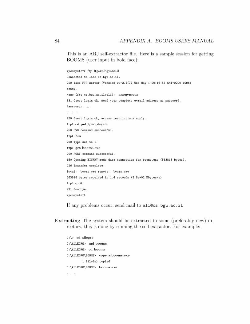
84 APPENDIX A. BOOMS USERS MANUAL
This is an ARJ self-extractor file. Here is a sample session for gettingBOOMS (user input in bold face):
mycomputer> ftp ftp.cs.bgu.ac.il
Connected to lace.cs.bgu.ac.il.
220 lace FTP server (Version wu-2.4(7) Wed May 1 20:16:54 GMT+0200 1996)
ready.
Name (ftp.cs.bgu.ac.il:eli): anonymous
331 Guest login ok, send your complete e-mail address as password.
Password: ...
. . .
230 Guest login ok, access restrictions apply.
ftp> cd pub/people/eli
250 CWD command successful.
ftp> bin
200 Type set to I.
ftp> get booms.exe
200 PORT command successful.
150 Opening BINARY mode data connection for booms.exe (563818 bytes).
226 Transfer complete.
local: booms.exe remote: booms.exe
563818 bytes received in 1.4 seconds (3.8e+02 Kbytes/s)
ftp> quit
221 Goodbye.
mycomputer>
If any problems occur, send mail to [email protected]
Extracting The system should be extracted to some (preferably new) di-rectory, this is done by running the self-extractor. For example:
C:\> cd allegro
C:\ALLEGRO> md booms
C:\ALLEGRO> cd booms
C:\ALLEGRO\BOOMS> copy a:booms.exe
1 file(s) copied
C:\ALLEGRO\BOOMS> booms.exe
. . .

A.3. BOOMS LOADING / COMPILING / RUNNING 85
A.3 BOOMS Loading / Compiling / Run-
ning
First thing you should make sure that the valid file types variable, *load-pathname-types*is bound to ’(#p".fsl" #p".lsp") (this is useful anyway), and that *default-pathname-defaults*is bound to the directory containing BOOMS. Changing the Lisp working di-rectory is another thing you would probably want to do. This can be doneby having these three lines:
(setf *default-pathname-defaults*
#P"C:\\ALLEGRO\\BOOMS\\")
(setf *load-pathname-types* (list #p".fsl" #p".lsp"))
(set-current-directory "C:\\ALLEGRO\\BOOMS")
added in C:\ALLEGRO\STARTUP.LSP file (assuming this is the Lisp installationdirectory).
Once you’ve got this done, loading, compiling, and running BOOMS issimple, each operation is performed by loading a file indicated in this table:
Loading LOAD.LSP
Compiling COMPILE.LSP
Running RUN.LSP
If the system is already loaded — the function ‘booms’ can be also used forrunning it.
Note that Allegro Lisp for Windows automatically compiles loaded func-tions, so compilation has affects only load-time, not run-time.
A.4 Using BOOMS
This section provides a brief description of using the system. This is basedon the assumption that the reader is already familiar with the hierarchicalediting ideas as described in this work. Specifically, these subjects should beclear:
• DAG representing an editing session operational hierarchy.
• Management of such a DAG.
• Creating and using a structure abstraction.

86 APPENDIX A. BOOMS USERS MANUAL
Anyway, this is just a brief description of BOOMS operations available tothe user, it is not a replacement for actual experimenting.
A.4.1 General Hierarchy Editing
The BOOMS hierarchy editor manages operational hierarchies based on aneditor domain. Each document in BOOMS (a file) contains an operationalhierarchy DAG consisting of nodes.
Nodes
A node is represented by a small rectangular icon with sockets that can beused as links to other nodes. Nodes are created by double clicking a clearspot on a document window, or by dragging a node-class name from the classpalette (see below).
Manipulating nodes is as simple as manipulating icons in any standardWindows applications. Selection is done by clicking nodes or by selecting asurrounding rectangle. If the shift key is held down, then the selected iconsare toggled rather than selected.
When the mouse pointer is over an icon, indicative text is printed on thestatus-bar, such as the node type, arguments and value. The icon is alsohighlighted to make sure that close nodes are not confused.
Double-clicking a node causes it to evaluate, this is visualized in someway that depends on the document type. Right clicking pops a node menu,that often contains operations specific for this node. Using this menu, orclicking the node with the Control key down pops up a node edit dialog thatis used to modify the node properties.
Sockets
Nodes have sockets near the top edge and near the bottom edge of the icon.The top socket is the output-value socket and the sockets on the bottom areinput argument sockets. There are three types of argument sockets for nodes:
1. A node can have a fixed number of arguments. An unconnected socketremains visible, and the node cannot there are any.
2. A node can have a list of arguments. Such a node can always beevaluated. When a link is deleted, its socket is deleted. The number of

A.4. USING BOOMS 87
visible sockets is always one more than the actual arguments connected:the extra socket is used for connecting new node arguments.
3. Finally, a “leaf” node is a node with no sockets at all — it is bound toappear at the bottom of the DAG.
Sockets are typed: the top socket determines the node evaluation valuetype, and the bottom argument sockets have types that determine whatoutput sockets can be linked to them.
Manipulating argument links is simple: connecting two nodes is per-formed by dragging a line from one node input (output) socket to the othernode output (input) socket. If the link is dragged to the socket body, thensome appropriate socket is selected by a default method. When the mousepointer is over a socket, the socket is highlighted indicating a link drag op-erations can begin, and the descriptive node description line on the statusbar is modified to show extra information on this socket. Deleting a link isdone by clicking its top socket to a clear document part (the bottom socketcannot be used for this as it is an output socket and a new link will be createdinstead).
Finally, an alternative way of modifying node arguments is by using thenode edit dialog box. This is the only way to specify constant [Lisp] valuesas being node arguments.
A.4.2 Document Types
A document type package is an implementation of some specific editor do-main, meant for hierarchy editing implementation in BOOMS. Each docu-ment type package defines a whole environment. The main definitions arefor specific node types, with some additional customized code like specificmenus and edit panes. Three document types are defined:
Music
This implements a simple hierarchical music editor. It is based on the MusicStructures approach. This package is intended to demonstrate the possibilityof a music editor implementation, much work should be invested to make thisan editor that can attract composers.

88 APPENDIX A. BOOMS USERS MANUAL
The node classes defined in this package are simple music concatenations,and some basic functions. Flat values are flat music pieces — double-clickingan icon visualize this by playing the music piece on a MIDI channel.
GCalc
The GCalc package implements the cube world defined at Chapter 4, basedon [19]. This package is the only package in BOOMS implementing a dualeditor: there are always two views connected to the same document, one ofthem is a “flat-form editor”, and the other is a hierarchical editor.
Node classes are cubes constructors, flat-form abstractions and applica-tion. Double-click visualization is done by displaying a window with the cubedrawing.
Arithmetic
This package implements the arithmetic example from Section 4. It is asimple example of a package implementation in BOOMS, that can be usedas a basic template for implementing more packages.
Node classes are arithmetic expression constructors. Evaluation of thesenodes yields an integer number, which is displayed in the status-bar upondouble-click evaluation.
Shared Icon Classes
There are several shared node classes that are available in all document types:
Identity Nodes These are icons that output the same value connected totheir input. They are useful for structure abstraction — when it isdesired to have the opposite behavior of the “Same-Node-Same-Arg”option:
When an icon list that is about to become an abstraction have oneargument connecting in more than one place, the Same-Node-Same-Arg option will determine the result. If this option is on, then a single-argument abstraction is created, otherwise each occurrence will have acorresponding argument socket.
An example will make this clear: if the expression 2 + 2, having thesame 2 object connected twice to a binary plus node, is abstracted onthe single 2 object then the result will be:

A.4. USING BOOMS 89
• X+Y if Same-Node-Same-Arg is off, and the two argument socketsX and Y are connected to the 2 object.
• X + X if Same-Node-Same-Arg is on, and the single X argumentis connected to the 2 object.
The intelligent reader can see that an identity node can be used in bothcases to have the opposite behavior.
Lisp Value Nodes Constant nodes contains a single Lisp value that is usedas the value of the node. They can be used only by a user that is awareof the underlying Lisp implementation and data types used.
Flat-Form Abstractions / Application These node types implement theflat-form abstraction and application operations. They are availableonly when the document-type package defines the needed search andreplace operations.
Text Nodes These are non-conventional nodes that cannot be part of theoperational hierarchy. They are used as text labels for decorating thehierarchy with short, descriptive messages.
A.4.3 The Class Palette
The class palette is a small floating window that is placed at right side of thescreen. The palette shows all available node classes, hierarchically ordered ina collapsible tree. The hierarchy is not determined by internal aspects suchas class inheritance, it is only for user-interface convenience.
The palette is used in three ways:
1. It gives a visual indication of the current node class selected.
2. Clicking on a class name makes it the current node class (double-clicking will create instance of this class).
3. The two operations of selecting a class and then creating an instance,can be compacted into a single click-a-class and drop-an-instance op-eration.
The classes menu is a equivalent to the classes palette and can be usedinstead.

90 APPENDIX A. BOOMS USERS MANUAL
A.4.4 Abstractions
Abstractions are created by selecting some icons and performing an abstrac-tion operation. This icon groups must stand in these conditions:
• The icon list compose a connected subgraph.
• This subgraph have a single root node (for determining the abstractiontype).
• All external links (going from nodes in the icon-list to other nodes) areeither from the root node upward, or from leaf nodes downward (leafnodes in the selected subgraph).
The abstraction created is an icon with the same output type as the rootnode of the abstracted icon group. This node contains argument links thatcorrespond to the external nodes that were connected as arguments to thegroup icons. If the Same-Node-Same-Arg option is set, then each argumentobject will have a matching abstraction input socket. If it is not set, theneach link will have an argument socket — if the same object has two links tothe group icons, two argument sockets will be created.
The created abstraction icon immediately replace the original group, andits input and output sockets are linked correctly so the DAG has basicallythe same values.
If the abstraction is named, its name will be added to the node classpalette, under the user-defined label. In this case, more instances of thisabstraction can be created. Named abstractions are labeled by their names,so they appear as a user defined function (abstraction names should indicatetheir operation).
Abstractions can be exploded by the user. This means the original nodesubgraph will replace the abstraction (with arguments correctly linked). Thiscan be done for an unnamed abstraction as well as on a named one.
This facility might be misused as a way for naming a subgraph for laterusing it (as a subgraph, not as the function it performs). This is better donewith the named-copy mechanism. This allows selecting a group of iconsand giving it a name that will appear in the named-copies section in theclass palette. This name can be later dragged to a document for creatinganother copy of the original group. This is better for the purpose of naminga subgraph and having more copies of it because:

A.4. USING BOOMS 91
• Named copies can be created from any group of icons.
• No need to abstract first and then explode.
• The operation is simple and quick — no tests are made.
A.4.5 Menu Commands
File Menu
File management operations:
New Create a new document. This will be done only after inquiring theuser for the new document type — selecting from the three packagescurrently implemented.
Open Open a saved document. BOOMS will automatically identify thedocument type and auto-load all named abstractions to the classespalette.
Close Close the active document. Offer to save the document if it wasmodified.
Close All Close all documents. Offer to save modified documents.
Save Save the current document. The saved information will include:
1. Document type.
2. Current DAG graph.
3. Named abstractions used
4. Window location, size and state.
5. Option settings.
If the document is saved for the first time, then the user is promptedfor a new name.
Save As Save the document under a new name.
Save All Save all documents.
Exit Exit BOOMS (offer to save modified documents). This will only exitthe current BOOMS session, not the Lisp application.

92 APPENDIX A. BOOMS USERS MANUAL
Edit Menu
When reading the documentation of clipboard operations, the reader shouldnote that BOOMS holds a separate clipboard for each document type.Icon editing operations:
Cut Cut the selected icons to the BOOMS clipboard (for the current type).The icons are copied with their internal links (links between membersof the selected icon list); external links are deleted.
Copy Copy the selected icons to the BOOMS clipboard (for the currenttype).
Paste Paste the icons in the BOOMS clipboard (for the current type).
Delete Delete the selected icons.
Edit icon Edit the current icon using the applicable edit pane list (see belowfor description of icon edit panes).
Grab style Grab (store) the current icon style. The icon style includes itscolors (background, foreground and highlight) and its font. The font iseffective only for text label nodes.
Apply Style Apply the current grabbed style to the selected icons. Thismeans that the selected node[s] will have the grabbed style. The fontstyle only applies only to text messages (only if the current grabbedstyle was taken from a text node).
Select All Select all icons in this document.
Clear All Delete all icons in this document. Warn the user first!
Abstract Menu
Abstractions operations:
Create Icon Iconify the selected icons to a single abstraction. This createsan unnamed abstraction — the selected icons are abstracted to anabstraction icon that replace them. No class name is added in the iconclass palette.

A.4. USING BOOMS 93
Explode Explode the selected abstraction[s] to the original components.This applies both to named and to unnamed abstractions. The originalnodes will replace the abstraction nodes, scattered around its location.
Name Name the selected abstraction — add it in the icon-class palette andmenu. If multiple icons are selected, an abstraction is created first andthen it is named.
Unname Unname the selected abstraction[s] — the selected named abstrac-tion icons are turned into unnamed abstractions.
Named Copy Create a named copy — copy the selected icons to a specialnamed register that appears on the icon-class palette. This can be laterused for pasting instances of this selection. The conventional “copy”operation is identical to this operation when the name is “clipboard”.
Remove Current Remove the selected user-defined abstractions or user-named-copy from the palette / menu. Removing a named-copy has noeffect other than removing the selected entry, but removing a named-abstraction will unname all of its instances in all documents (this re-quires user-confirmation).
Remove Unused Remove unused abstraction entries from the palette /menu for this type. This will scan all named abstractions currentlyavailable for the current document type, and remove the entries for theunused abstractions. An abstraction is not used only if no document(of the current type) contains an instance of it.
Remove Copies Remove all named copies from the palette / menu for thistype. Note that named-copies cannot be used in a document.
Classes Menu
This menu holds all icon-classes. It is equivalent to the icon-class palette.Only the sub-menu corresponding to the current document type is available.
Windows Menu
This menu contains two sections, one for toggling panes (showing / hidingthem), and one for selecting a document window:

94 APPENDIX A. BOOMS USERS MANUAL
Toggle Palette Toggle the icon classes palette.
Toggle Status-bar Toggle the BOOMS Status-bar.
Toggle Toolbar Toggle the BOOMS Toolbar.
Document Window Selections These entries, one for each active docu-ment, select one them.
Options Menu
Various BOOMS options — these are general operations, and option settingfor the current document:
Same-Node-Same-Arg This determine BOOMS behavior when abstrac-tion to be created has an argument appearing in several places. If thisis turned on, then each appearance will create another argument slot,and if it is off, then each single node argument will produce a singleslot.
Dialog create Toggle creating an icons with a dialog — whenever an iconis created, an edit dialog box immediately pops up for editing the newicon. Pressing the “Cancel” button will undo the icon creation.
Grid Toggle grid placement for icons — if this is on, then icons can only beplaced on grid locations, making it easy to organize icons “neatly”.
Refresh Refresh the screen — redraw the whole screen in case of mess dueto bugs (this should not happen).
Stop Music Stop playing MIDI music — clear the current MIDI musicbuffer.
Garbage Collect Run a Lisp garbage-collection.
Help Menus
General information menu, there is no “real help” here.
Welcome Hello from BOOMS. . .
About BOOMS This pops up a dialog box showing the contents of BOOMS.TXT,containing the BOOMS abstract.

A.4. USING BOOMS 95
Context Sensitive Menus
Context-sensitive menus are activated on a mouse right-click operation. Thereare three context-menu types:
1. Right-clicking the application window (the pane available between doc-ument windows) pops up a menu with these options:
• Create a new document.
• Open a document.
• Close all documents.
• Save all opened documents.
• The whole Windows menu is also available.
2. Right-clicking a document area (not inside an icon) pops up a menuwith these options:
• Save this document.
• Close this document.
• The whole Classes menu is also available.
3. Right-clicking an icon pops its own specialized menu, this contain:
• Evaluate, which is equivalent to double-clicking the icon.
• Edit, which pops up the edit-icon dialog.
• More options are available, according to the specific node type.These options are part of the document-type package.
A.4.6 Keyboard / Toolbar Shortcuts
Accelerator keys and toolbar buttons are a standard GUI feature. The Win-dows operating system has a lot of conventional accelerator key bindings,many of them are used in BOOMS.
A list of all accelerator keys is given below. “C-” means holding theControl key, “S-” means holding he Shift key and “A-” is the Alt key.

96 APPENDIX A. BOOMS USERS MANUAL
Key Operation Key Operation
C-N New Document C-O Open DocumentC-W Close Document C-S Save DocumentC-F4A-X Exit BOOMS C-X Cut
S-DelC-C Copy C-V PasteC-Ins S-InsDel Delete A-Enter Edit NodeC-DelC-G Grab Style C-P Apply StyleC-A Select All C-I Create Abs.C-E Explode Abs. C-M Name Abs.C-S-C Named Copy F10 Palette Togg.F11 Status-bar Togg. F12 Toolbar Togg.S-C-D Dialog Create Togg. S-C-G Grid Togg.C-R Refresh Screen M-F4 Close LispArrows Move Icons S-Arrows Fast IconsC-Arrows Scroll Window C-S-Arrows Fast ScrollC-Tab Next Document
The BOOMS toolbar provides many useful shortcuts — just point themouse to a button and a message describing its operation will appear nearit, and at the status-bar. The is one operation that is available only fromthe toolbar, volume setting (the right track-bar).
A.4.7 Node Edit Panes
A useful feature that is standard in Windows is attribute panes. These existfor many objects and can be popped by choosing properties from a menu(usually the right-button menu associated with the object) or by pressing“Alt+Enter”. A property dialog box is mostly made using a tab control toswitch different pages, each is used for some different attribute changing.
In BOOMS, the node edit dialog contain property edit panes. This featureis fully customizable by package implementations — each node can have itsown set of property pages.
Here is the list of current edit pages and their usage:

A.4. USING BOOMS 97
node This is the most important edit page. It allows editing of node ar-guments — linking node arguments, or disconnecting them. This alsoprovides the only possible way for filling an argument socket with aLisp value.
This page is available to all nodes (not to leaves).
leaf This page is available to all leaf nodes. It controls the leaf value.
colors This page is available to all nodes. It is used to determine the colorsused for nodes. The colors are the foreground and background colorsused to draw icons with, and the selection highlight background color.
text This page is only for text message nodes. It controls the text messagedisplayed, its font and its color.
notated This page is for editing notated triplets naming pitch or intervalvalues in the music package.
sound This page is for editing a sound node in the music package.
factor This page is for editing music package factor values (real numberbetween 0 and 1).
g-color This is used in the GCalc package by primitive cubes — selectingthe cube color. Note that it is available to the general cube, constant-color cubes cannot change their colors.
arith-name This is a general page for all nodes classes in the arithmeticpackage. These nodes have a “name” that can be modified using thispage. It is not very useful, but it is for demonstration purpose.
operator The arithmetic package defines general operator nodes, that canhave one of several Lisp functions available. This page is used to changethis operator.

98 APPENDIX A. BOOMS USERS MANUAL

Appendix B
BOOMS ProgrammersReference
These appendix is not complete yet, currently there is only the files docu-mentations.
B.1 Document Type and Icon Class Addi-
tions
As written in this work many times, BOOMS is designed to make additionsof editing domain packages very easy. The arithmetic package implementa-tion file, ARITH.LSP, is provided mainly as a template for learning how newpackages should be implemented. See the detailed documentation for thisfile.
B.2 Lisp Code Explanations
B.2.1 The Files
This is a list of BOOMS files and a brief description of each. The nextsections contain full explanations for the important files — the files markedwith a ⋆.
HEADER This is a simple header file for the whole system, providing the logoand date on the self-extractor file and on after the system is loaded.
99

100 APPENDIX B. BOOMS PROGRAMMERS REFERENCE
FILELIST This is the list of all files, used only for creating the compressedfile.
ARJBOOMS.BAT This is a small batch-file that creates the compressed file.
BOOMS.TXT This is the BOOMS short abstract that is displayed when usingthe “About Booms” menu command.
BOOMS.TEX The source of this work.
B-FILES.LSP ⋆ This defines the load and compile mechanisms. It provides‘makefile’ mechanisms for reload / recompile when needed. The needfor such a file arise as this Lisp version does not contain the defsystemfacility.
LOAD.LSP When this file is loaded, the whole system is loaded — if this wasalready done then only modified files will be reloaded.
COMPILE.LSP When this file is loaded, the whole system is recompiled. Onlynew files will be compiled
RUN.LSP When this file is loaded, the whole BOOMS system is loaded andthe application is launched.
PACKAGES.LSP ⋆ Definitions for the packages, symbols imports and symbolsexports.
NETWORK.LSP ⋆ This is the main core of BOOMS. It defines the basic ‘Node’class that compose an operational hierarchy DAG.
BOOMSAPP.LSP ⋆ The main Windows application definitions.
BOOMSDOC.LSP ⋆ The ‘Document’ class definition. When speaking of the‘Document-View’ approach, this file is actually the hierarchical viewimplementation and NETWORK.LSPis the real document.
ICONS.LSP ⋆ Definitions for the ‘Icon’ class which is used to add GUI meth-ods for nodes and create the ‘Iconic-Node’ class.
LEAVES.LSP ⋆ This defines GUI leaf nodes.
ABSTRACT.LSP ⋆ Definitions for visual hierarchical abstractions. The actualabstraction mechanism is in NETWORK.LSP.

B.2. LISP CODE EXPLANATIONS 101
SHARED-I.LSP ⋆ The shared icon classes are defined in this file.
CLASSPAL.LSP ⋆ The definitions for the icon classes palette, and the mech-anism for run-time addition of classes.
ICONEDIT.LSP ⋆ This defines the icon edit dialog mechanism, supportingcustomizable property edit pages.
COLEDIT.LSP ⋆ Definitions for the icon color edit pane.
SAVELOAD.LSP ⋆ Saving and loading BOOMS documents.
MUSIC.LSP ⋆ The music sample package.
ARITH.LSP ⋆ The arithmetic sample package.
GCALC.LSP ⋆ The implementation of the GCalc double view editor.
MISC.LSP ⋆ Miscellaneous useful definitions.
GR-MISC.LSP ⋆ Miscellaneous GUI definitions, like the color-box widget.
GEOMETRY.LSP ⋆ Geometrical efficient functions.
CONSTANT.LSP ⋆ All constants are defined in this file. This can be modifiedto make the application look different.
DIALOGS.LSP ⋆ Several common dialogs that are used in BOOMS are definedhere.
BITMAPS.LSP ⋆ Bitmaps for the toolbar buttons.
MIDI-LIB.LSP ⋆ This is the Lisp interface to the MIDI driver.
MIDI-LIB.DLL This is the MIDI driver DLL.
MIDI-LIB\MIDI-LIB.H The header file for the MIDI driver library.
MIDI-LIB\MIDI-LIB.C ⋆ C functions that implement the simple MIDI driver.
MIDI-LIB\MIDILIB.MAK MsDev automatically generated makefile.
MIDI-LIB\MIDILIB.MDP MsDev project file.

102 APPENDIX B. BOOMS PROGRAMMERS REFERENCE
ICONS.DLL Icons that used in BOOMS — for node icons and the windowicons.
LOGO.BMP The bitmap that pops when BOOMS is started.
INTRO.WAV The wave file for the logo pop-up.
NETWORK.EXA ⋆ This is an example of using the bare BOOMS core (in NETWORK.LSP)with no Graphic User Interface.

Appendix C
The GCalc Mini System
C.1 Scheme Implementation
This system is written in Scheme, the implementation used is John Kozak’s1
Scheme version of SCM (by Aubrey Jaffer2). The system was written on topof bitmap.scm which is a simple object-oriented extension to the WindowsScheme that makes life simple (written by the author).
This should work for any true 32-bit Windows, but due to some uniden-tified bug, it works only on some Windows 95 versions (on some, it worksbut it does not actually draw anything).
C.2 FTPing, Extracting, Running
The GCalc system is at the same FTP site as BOOMS and getting the file isdone exactly like getting the BOOMS file, see Section A.2. The file name isgcalc.exe, it is also an ARJ self-extractor that should be extracted at theroot of the “C” hard-disk (the whole system is about 5Mb).
Running the system is simple, no compiling is needed. The batch filescm\gcalc.bat will run the system.
[email protected]@ai.mit.edu
103

104 APPENDIX C. THE GCALC MINI SYSTEM
C.3 System Documentation
This documentation is from the Scheme file. It is only LATEX-ized, so it mightnot follow the overall style of this work.
C.3.1 General Description
The basic description language is composed of simple basic objects and con-structors that compose more objects. The word ‘object’ can mislead thereader to think of a world of objects with identities. This is not the case —and the word object should be read as values that are represented by GUIobjects.
• The basic objects are solid colored cubes. The exact colors have noimportance, a transparent cube is usually useful.
• All objects are cubes, and composing them using the constructors cre-ates new objects which are also cubes.
• There are three constructors which correspond to the three axes: Left-Right, Top-Down and Front-Back constructions. Each constructiontakes two objects and produces another — the result is a cube splitinto two halves containing the two original objects.
This world is perfect for the purpose of demonstrating lambda calculussince it is on one hand very simple, and on the other hand graphic so a visualinterface is perfect here.
C.3.2 Functional World
In order to make this description language into a functional language weneed to implement functions and the rules for handling them. This is theimportant step here. Two operations are added — lambda abstraction andapplication (beta-reduction). Lambda abstraction means taking an expres-sion and making one of its components a variable, and application meanstaking a lambda abstraction’s body and replace each occurrence of the vari-able by the application argument.

C.3. SYSTEM DOCUMENTATION 105
C.3.3 Visualization
The visualization of basic objects and simple constructions of them is straight-forward — we use a simple three dimensional cube that is the exact cube tobe drawn. The two other cases are a bit more complex.
• Basic cube: Simply draw this cube as a three dimensional object. Notethat this can also be the case for variables — we have to draw variablecomponents of expressions as the original object. See explanationsbelow.
• Construction: Draw the two parts of the construction in the two halvesdefined by the constructor’s axis.
• Application: Note that an application does not appear too often, sincein most cases it is immediately evaluated (= reduced) — this followsfrom the evaluation rules below. There are only two cases where anapplication can ‘survive’ evaluation — one is the application of a basiccube, which has no meaning except the application itself, so there’snothing to do but to leave this application in place, this can also occurwhen applying such an application again on another object. The othercase can happen as a result of applying some function to an object — ifthis function is of more than one variable (curried), then the result willbe the simple substitution result — no re-evaluation of the body. Anapplication object is visualized as the object being applied behind itsargument, in the same dimension size relation so it can’t be confusedwith a front-back construction.
• Lambda Abstraction: An abstraction is simply shown as the body ofthe abstraction with a little circle which represents the variable object.A lambda abstraction inside another will be drawn as having two circledvariables (or more) one next to the other.
There is something that should be said here on variables — I can’tuse the substitution model without renaming, so the renaming I usepreserve the object that was turned into a variable. This way thevariable object can have a color, and the body is still visualized thesame. See an explanation below for why the substitution model mustbe used.

106 APPENDIX C. THE GCALC MINI SYSTEM
C.3.4 System Description
The system is very simple and follows exactly the principles above. Thereare three windows — main window and two floating toolbars.
The main window provides the “work-space”, it has a cell for the ‘selectedobject’ which is being worked on, and eight surrounding cells. Draggingan object to the center cell just put that object instead of what was therebefore. Dragging an object to the other eight cells performs an operation— three cells create a construction, and three more construct an ‘opposite’constructions (switching the first and second arguments). The applicationcells constructs an application (one way or the opposite) that is immediatelybeing evaluated — all other applied objects are reduced.
The other two panes are the ‘Basics’ pane and the ‘Objects’ pane. TheBasics pane contains the basic objects that are used to build all compoundobjects — all color cubes and the transparent cube. This pane cannot bemodified and it is created once on startup. An important role of this pane isfor constructing lambda abstractions — when a basic object is right clickedthe selected object will be abstracted using the basic color clicked as a vari-able. The Objects pane is a store place to save objects that are needed inthe flow of work. Objects can be dragged to the objects pane and back.
Learning how to work with the system is easy — it is a simple, small tool.There are few useful operations that are all specified below.
‘H’ Shows a help screen that describes these operations.
Left-mouse drag n’ drop This is for dragging objects to store locationsor to the selected cell. It is also used to drag objects to the action cells.
Right-mouse click Use this to zoom-in an object. All objects are actu-ally drawn on the zoom pane, so viewing a zoomed object means noadditional processing. Another important use of a right click (speci-fied above) is constructing a lambda abstraction — this happens whenclicking a basic object, which will be used as the variable for the newabstraction. There is also a minor operation for a right button click —on an action cell it will negate the action, for example on the ‘top’ cellit’ll only leave the bottom part etc.
‘N’ This tends to be very useful for demonstration purposes — it will namethe selected object, so objects can have a descriptive name.

C.3. SYSTEM DOCUMENTATION 107
‘D’ This toggles visual drawing on/off. Usually the objects are drawn visu-ally, this helps sometimes understanding the visual object’s structurebut slows evaluation.
‘C’ This will clear the selected object. It is useful only for saving files —loading will reevaluate all expressions so it can be useful to delete ob-jects. The cleared cell is such that can be dragged to the Objects paneso other cells can be cleared.
‘S’ This will save a file with all objects on the Objects pane and the selectedcell.
‘L’ This will load a saved file. Note that loading means reevaluating allobjects to draw them, so this operation might take a while — thevisual drawing can be turned off for speed.
‘R’ Restarting the system — clear the Objects pane and the selected cell.
‘Esc’ Quit.
C.3.5 Building Expressions
The system description above implies that objects are built step by step.This means that the Objects pane must be used from time to time to storeintermediate result while building some complex objects. Another importantfeature of the system is that all applications constructed are immediatelyevaluated — reduced. One important result of this is that we can’t use theextended application rules specified in the Grame paper — the rules thatassign functional meaning to basic objects.
These rules give all objects a functional meaning, for example, the redcube can be used as the ‘reddish’ operator — the application of red on whiteproducing a pink cube. However, using these rules in this system means wecannot construct abstractions that contains applications since these appli-cations will be immediately reduced — when we’ll try to build somethinglike “(λ (red) (red white))”, we’ll get instead “(λ (red) pink)”. This isbecause we must construct the red-white application, and we don’t have anyway of preventing this application from being evaluated. See the “functionalextensions” section below for further discussion.
108 APPENDIX C. THE GCALC MINI SYSTEM
C.3.6 The Evaluation Model
The first question that should be asked when implementing this system iswhat model will be used for evaluating expressions. There are two immediateoptions here — the substitution model and the environment model. When Istarted working on the system I first tried using the environment model —it looks as if it is much more efficient using it.
Using the environment model leads to many problems. The first prob-lem is that our objects should have some kind of a visual representation forobjects. It is not a general problem, but it makes other problems get worsesince it makes visualization unnatural. Another problem is where should theexpressions be evaluated — an abstraction should produce a closure, andthis closure should contain some kind of an environment. This comes as aproblem considering the nature of this system, that is, the step-by-step con-struction of objects. When we’ll want to construct a two variable lambdaabstraction like:
(λ (red) (λ (yellow) (left-right red yellow)))
we will have to first construct the inner expression — in the global environ-ment, so when later the whole expression is applied, the outer variable willnot be bound in the inner one’s environment. A possible solution will be tonot evaluate lambda abstraction, but then the environment model advantageis lost and the results will not be visualized properly.
The other option is a lot more reasonable here — the substitution model.It is more natural, since this is the way we actually think of using lambda ab-stractions — what we expect to see as a result of applying an abstraction like“(λ (red) red)” on “green” is indeed “green” and not “red” in an environmentthat binds it to “green”. This means that using the environment model willjust be an attempt to simulate substituting with the wrong model. There isonly one problem to solve here — avoiding variable capturing, this requiresrenaming. But — names here are basic colored objects, and they should belater visualized, so the original variable should be kept — so to represent avariable I use a list that contains the variable name and some number. Thismeans that not all information is shown on the screen so confusing situationscan arise, like the result of applying
(λ (red) (λ (green) (left-right red green)))

C.3. SYSTEM DOCUMENTATION 109
on green will be visualized like
(λ (green) (left-right green green))
but the first green of this construction is a green cube, and the second is agreen variable.
C.3.7 Reduction Rules
The last thing (and the most important one) to specify is the reduction rulesused. The syntax of the GCalc system is very simple, but there should bean exact specification of the semantics — object evaluation rules.
This is quite simple, and it’s best demonstrated by the eval-exp1 func-tion’s simplicity (just 17 lines). Note that this function is used only on anapplication operation.
Note that these rules do specify the extended reduction rules that givesa meaning to a construction of abstractions. This means that a function canbe composed of several parts, and applying such a function will be done byapplying each part on the corresponding argument’s part. See the rules forexact definition of this.
The rules follow:
Simple expression Just return the expression. These expressions includeboth basic objects and variable objects.
Construction expressions These expressions are simply evaluated recur-sively, formally, the expression “(left-right x y)” will be evaluated to“(left-right x′ y′)” when x′ and y′ are the evaluations of x and y respec-tively.
A question can be asked here — is this really needed? Well, in mostcases it is not needed, we can simply return the expression as it is.However, there are some rare occasions where the result of an applica-tion returns an object which is a construction of applications, such asapplying this function on identity (for example, “(λ (green) green))”:
(λ (red) (left-right (red yellow) (red cyan)))
The result of the substitution would be:
(left-right ((λ (green) green) yellow) ((λ (green) green) yellow))

110 APPENDIX C. THE GCALC MINI SYSTEM
But this should be further reduced to:
(left-right yellow cyan)
This can happen only as a result of an application, which implies apossible optimization — use a simple version of eval-exp1 for all ex-pressions, and make the application evaluation use another version thatwill actually evaluate constructions. This can be simplified by not usingeval-exp1 for any expressions except applications. This is the causeof the conditional call in eval-exp.
Lambda Abstraction expressions Abstractions are also returned as theyare, these expressions does not have to be evaluated — they are givena variable when first constructed and only change when applied. Notethat this case can be considered the same as the construction expres-sions above — we might want to compute the body of a function assoon as this is possible, however, this is not wanted since the functionshould be applied again sometimes to get a final result (not a function),so it is not necessary to do the evaluation. This is actually a kind of anormal-order evaluation — where function bodies are not evaluated ex-cept when needed. This alone is not enough for normal order evaluationsince other rules should do a similar thing (see below).
Application Expressions This is where there is some job to be done. Notethat we wouldn’t have to use the evaluation function recursively unless,during some applications, there will be more [nested] applications thatcan be evaluated now. We now split into cases based on the evaluatedversion of the object being applied:
Simple expressions There’s nothing we can do with these expres-sions, so they are returned as they are (this would be the place toadd the extended evaluation rules).
Application expressions This is also treated as a simple expressionwith nothing much to be done, since the expression is anywaysomething that is not a simple (non-function) object.
These expressions could be further evaluated in case of a substi-tution, and not doing this creates the normal order effect — seethe rule for reducing lambda abstractions above for further ex-planations. For example, this enables us to enter this expression

C.3. SYSTEM DOCUMENTATION 111
without getting into an infinite loop (however, evaluating its ap-plication on a function will get us into the unavoidable loop):
(λ (red) (λ (blue) (red (blue blue)))(λ (blue) (red (blue blue))))
Abstraction expressions Here we replace the application argumentfor the abstraction variable in the abstraction body, and returnthe evaluation of this substitution result (calling the evaluationfunction recursively).
Construction expressions This is the special extension of a functionobject. This extension gives functional meaning to constructionsof functions. What is being done here is applying a function parton the corresponding argument’s part. For example, the result ofthis application:
((left-right f1 f2) obj)
would be:
(left-right (f1 (left-part obj))(f2 (right-part obj)))
And now the formal generalization of this example should be ob-vious now. This operation must be done only when the object isconstructed in the correct direction, therefore, it is used on theresult of a split function that will make the object a construct inthe correct size (splitting it if it is not already split in the correctdirection). Note that this evaluation rule is really powerful — itenables the usage of “cubes of functions” on other cubes. Thereis little meaning to cubes of abstractions with different “lambdalengths” (objects like half functions and half basic colors), butthere is no error checking.
[Last remark — following this rule exactly explains why the Grame’s“Spenger Sponge” won’t work as shown in their paper, see the lastsection below.]
C.3.8 Functional Extensions
Now that we’ve seen the GCalc definition we can spend a thought on theextensions. The one extension I have implemented is the construction offunctions, which is taken as a function that does something on one half and

112 APPENDIX C. THE GCALC MINI SYSTEM
another on the other half. This is quite natural to understand, and very usefulwhen using the system for tricky demonstrations. This extension makes theGCalc world more consistent in the sense that the new objects introduced— abstraction and application, can be taken like all other objects, so it ispossible to use them with constructions.
The Grame paper specifies another extension — we have our new objectsbehave like any other object by now, what we want is the other way — havesimple objects behave like functions when they are applied. This was notdone in Grame’s system as well as in this system for two main reasons:
1. Implementing this means there should be a mechanism that will specifywhen we actually want to evaluate an expression. This is because(as already said above) the expressions are built piece by piece fromthe inside parts to the outside. This will prevent us from buildingsome expressions as specified above (“building expressions” section). Asolution for this will very easy to implement, simply have some eventlike a key-press or double-click evaluate the selected object, but it’llmake the system somewhat too complex to be fun — keeping in mindthat expressions should get evaluated sometime.
2. This meaning of basic objects as functions (red as a reddish functionetc.) is the most natural choice, however, it is not natural enough tomake a user mad about not having this feature.
So, to conclude, this extension was not implemented for the sake of keep-ing this a “toy system” that will be fun to play with. This has caused theevaluation function to look a bit messy (when trying to dig inside it and seewhat do get evaluated and what not — see the above section), but the resultis worth this. A serious implementation would have this feature, but thenagain — what serious things can be done with this cube world?
C.3.9 Formal Definition of GCalc
The formal definition of the GCalc system is given at Sections 4.3, 5.2.1 and5.2.3.

Bibliography
[1] Felix Salzer. Structural Hearing: Tonal Coherence in Music. DoverPublications, 1962.
[2] E. Narmour. Beyond Schenkerism: The Need for Alternatives in Music
Analysis. The University of Chicago Press, 1977.
[3] Fred Lerdahl and Ray Jackendoff. A Generative Theory of Tonal Music.The MIT Press, 1983.
[4] Terry Winograd. Linguistics and the computer analysis of tonal har-mony. Journal of Music Theory, 12:2–49, 1968.
[5] O. Laske. Introduction to a generative theory of music. Sonological
Reports, 16, 1975.
[6] O. Laske. Composition theory: An enrichment of music theory. INTER-
FACE, Special Issue on Models of Musical Communication and Cogni-
tion, 18(1–2):45–59, 1989.
[7] S.W. Smoliar. An approach to music theory through computationallinguistics. Journal of Music Theory, pages 105–131, 1976.
[8] M. Kassler. Explication of the middleground of schenker’s theory oftonality. Miscellanea Musicologica, 9:72–81, 1977.
[9] A.X. Rodet and P. Cointe. Formes: Composition and scheduling ofprocesses. Computer Music Journal, 8(3):32–50, 1984.
[10] W. Buxton, W. Reeves, R. Baecker, and L. Mezei. The use of hierarchyand instance in a data structure for computer music. Computer Music
Journal, 2(4):10–20, 1978.
113

114 BIBLIOGRAPHY
[11] R.B. Dannenberg, P. McAvinney, and D. Rubine. Arctic: A functionallanguage for real time systems. Computer Music Journal, 10(4):67–78,1986.
[12] Mira Balaban. The music structures approach to knowledge represen-tation for music processing. Computer Music Journal, 20(2):96–111,1996.
[13] D.V. Oppenheim. Dmix: A multi faceted environment for compositionand performing computer music: Its design, philosophy, and implemen-tation. In Computer Music Days, pages 1–10, Delphi, Greece, 1992.
[14] S. Letz, Merlier, and Y. Orlarey. Common lisp compositional environ-ment : Manuel de reference. Technical report, GRAME, Lyon, 1990.
[15] Mira Balaban and Yan Orlarey. Score ontology: A step towards con-structing a formal semantics for computer music tools. Technical report,Department of Industrial Engineering and Management, Ben-GurionUniversity, Beer Sheva and Department of Musicology, Bar-Ilan Uni-versity, Ramat Gan, Israel, and GRAME, Lyon, France, 1996.
[16] J. Gourlay. A language for music printing. Communications of the ACM,29:388–401, 1986.
[17] G. Loy. Musicians make a standard: The midi phenomenon. Computer
Music Journal, 9(4):8–26, 1985.
[18] Keith McMillen. Zipi: Origins and motivations. Computer Music Jour-
nal, 18(4):47–51, 1994.
[19] Y. Orlarey, D. Fober, S. Letz, and M. Bilton. Lambda calculus and musiccalculi. In International Computer Music Conference. San Francisco:International Computer Music Association, 1994.
[20] H. Taube. Stella: Persistent score representation and score editing incommon music. Computer Music Journal, 17(4):38–50, 1993.
[21] Charles Rich and Richard C. Waters. The Programmer’s Apprentice.Addison-Wesley Publishing Company, 1990.
[22] D.J. Kurlander. Graphical Histories. PhD thesis, Columbia University,Computer Science, 1992.

BIBLIOGRAPHY 115
[23] Simon L. Peyton Jones. The Implementation of Functional Programming
Languages. Prentice-Hall, 1986.
[24] Manojit Sarkar and Marc H. Brown. Graphical fisheye views of graphs.In Human Factors In Computing Systems, pages 83–92, 1992.
[25] Krasner G.E and S.T. Pope. A cookbook for using the model-view-controller user interface paradigm in smalltalk-80. Journal of Object-
Oriented Programming, 1(3):26–49, 1988.
[26] Ben Shneiderman. Designing the User Interface, Strategies for Effective
Human-Computer Interaction. Addison-Wesley Publishing Company,second edition, 1992.
[27] David Harel. On visual formalisms. Communications of the ACM,31(5):514–529, 1988.
[28] Guy L. Steele Jr. Common Lisp: The Language. Digital Press, 2ndedition, 1989.
[29] M. Balaban and C. Samoun. Hierarchy, time and inheritance in musicmodelling. Langugaes of Design, 1(2):147–172, 1993.