BELT CONVEYORS · Conveyor belt alignment moni tors must be wired properly into the control...
136
Part Number: P115506 R2 Revised: 24/1/14 Read this manual before using product. Failure to follow instructions and safety precautions can result in serious injury, death, or property damage. Keep manual for future reference. BELT CONVEYORS HI ROLLER, MINI ROLLER, LO ROLLER & HI LIFE ASSEMBLY, OPERATION, & MAINTENANCE NORTH AMERICAN VERSION ORIGINAL INSTRUCTIONS A division of AgGrowth Industries: 5100 West 12th Street, Sioux Falls, SD 57107 Toll free (US & Canada): 800-328-1785 / Phone: 605-332-3200 / Fax: 605-332-1107 www.hiroller.com / e-mail: [email protected]
Transcript of BELT CONVEYORS · Conveyor belt alignment moni tors must be wired properly into the control...

BELT CONVEYORS
HI ROLLER, MINI ROLLER, LO ROLLER & HI LIFEASSEMBLY, OPERATION, & MAINTENANCENORTH AMERICAN VERSION ORIGINAL INSTRUCTIONS
A division of AgGrowth Industries: 5100 West 12th Street, Sioux Falls, SD 57107
Toll free (US & Canada): 800-328-1785 / Phone: 605-332-3200 / Fax: 605-332-1107
www.hiroller.com / e-mail: [email protected]
Part Number: P115506 R2
Revised: 24/1/14
Read this manual before using product. Failure to follow instructions and safety precautions can result in serious injury, death, or property damage. Keep manual for future reference.

This product has been designed and constructed according to general engineering standardsa. Other local regulations may apply and must be followed by the operator. We strongly recommend that all personnel associated with this equipment be trained in the correct operational and safety procedures required for this product. Periodic reviews of this manual with all employees should be standard practice. For your convenience, we include this sign-off sheet so you can record your periodic reviews.
a. Standards include organizations such as the American Society of Agricultural and Biological Engineers, American National Standards Institute, Canadian Standards Association, International Organization for Standardization, EN Standards, and/or others.
Date Employee Signature Employer Signature
TABLE OF CONTENTS
HI ROLLER - BELT CONVEYORS HI ROLLER, MINI ROLLER, LO ROLLER & HI LIFE
1. Introduction .......................................................................................................................... 71.1. General Description.................................................................................................. 8
2. Safety .................................................................................................................................... 92.1. General Safety Information ...................................................................................... 92.2. Installation Safety ................................................................................................... 102.3. Operational Safety.................................................................................................. 112.4. Maintenance Safety................................................................................................ 11
2.4.1. Lockout and Tagout Procedures .............................................................. 122.5. Electric Motor Safety .............................................................................................. 122.6. Safety Decals ......................................................................................................... 12
2.6.1. Decal Installation ...................................................................................... 122.6.2. Safety Decal Locations............................................................................. 13
3. Conveyor Components...................................................................................................... 173.1. Operator Orientation............................................................................................... 173.2. Component List ...................................................................................................... 17
3.2.1. Head Sections & Discharges.................................................................... 183.2.2. Motor & Drive Mountings .......................................................................... 183.2.3. Trunking Sections..................................................................................... 193.2.4. Covers ...................................................................................................... 203.2.5. Inlets/Loader............................................................................................. 223.2.6. V-Plow ...................................................................................................... 233.2.7. Tail Sections ............................................................................................. 243.2.8. Take-Up Sections ..................................................................................... 24
4. Application Design Considerations ................................................................................. 274.1. Product/Capacity Considerations ........................................................................... 27
4.1.1. Aspiration.................................................................................................. 274.2. Clearances ............................................................................................................. 284.3. Discharge Considerations ...................................................................................... 294.4. Inclines ................................................................................................................... 294.5. Trunking Installation ............................................................................................... 294.6. Loading Considerations.......................................................................................... 30
4.6.1. Special Loading Applications.................................................................... 314.6.2. Loading Goals .......................................................................................... 31
4.7. Splices.................................................................................................................... 334.8. Supports ................................................................................................................. 334.9. Grounding............................................................................................................... 33
P115506 R1 3

TABLE OF CONTENTS
HI ROLLER - BELT CONVEYORS
HI ROLLER, MINI ROLLER, LO ROLLER & HI LIFE
5. Installation .......................................................................................................................... 355.1. Pre-Installation........................................................................................................ 355.2. Head End & Tail End Trunking Installation............................................................. 35
5.2.1. Head Section Mounting ............................................................................ 355.2.2. Tail Section Mounting ............................................................................... 375.2.3. Trunking Installation.................................................................................. 375.2.4. Tail Section Back Cover Removal & Installation....................................... 39
5.3. Inlet/Loader Installation .......................................................................................... 405.3.1. Skirt Installation ........................................................................................ 415.3.2. Discharge Considerations......................................................................... 42
5.4. Belt Installation ....................................................................................................... 425.4.1. Pre-Installation.......................................................................................... 425.4.2. Belt Squaring & Cutting ............................................................................ 425.4.3. Splice Protector / Wiper Cleats................................................................. 465.4.4. Lubrication ................................................................................................ 485.4.5. Belt Tension Procedure ............................................................................ 485.4.6. Normal Idler Wear..................................................................................... 51
5.5. Leveling Tail Take-Up Section................................................................................ 525.6. V-Plow Adjustment ................................................................................................. 525.7. Cover Installation.................................................................................................... 53
5.7.1. Made-To-Length Covers........................................................................... 535.7.2. Cut-To-Length Covers .............................................................................. 545.7.3. Cover Hardware........................................................................................ 55
5.8. Drive & Motor Final Check Before Start-Up............................................................ 565.9. Hazard Monitoring Devices .................................................................................... 56
5.9.1. Motion Sensor........................................................................................... 565.9.2. Plug Switch ............................................................................................... 585.9.3. Belt Alignment Monitors............................................................................ 595.9.4. Belt & Pulley Alignment Monitors.............................................................. 68
5.10. Final Checklist ...................................................................................................... 745.11. Test Start-Up ........................................................................................................ 765.12. Final Inspection During Operation ........................................................................ 76
6. Operation ............................................................................................................................ 796.1. Pre-Operational Checklist....................................................................................... 796.2. Conveyor Drive & Lockout Procedure .................................................................... 796.3. Operating Procedure .............................................................................................. 79
6.3.1. Start-Up and Break-In............................................................................... 796.3.2. Operating with a Full Load........................................................................ 806.3.3. Shutdown.................................................................................................. 806.3.4. Operating Tips .......................................................................................... 816.3.5. Plugging.................................................................................................... 81
4 P115506 R1

TABLE OF CONTENTS
HI ROLLER - BELT CONVEYORS HI ROLLER, MINI ROLLER, LO ROLLER & HI LIFE
7. Maintenance ....................................................................................................................... 837.1. Maintenance Schedules ......................................................................................... 83
7.1.1. Basic Preventative Maintenance Schedule .............................................. 837.1.2. Lubrication Schedule ................................................................................ 83
7.2. Belt Tracking Guide................................................................................................ 847.2.1. Belt Tracking - Hi Roller & Mini Roller Models.......................................... 857.2.2. Belt Tracking - Hi Life Models................................................................... 897.2.3. Belt Tracking - Lo Roller & Hi Bulk Models............................................... 917.2.4. Belt Tracking Misalignments..................................................................... 937.2.5. Belt Camber.............................................................................................. 937.2.6. Skew (Bow) .............................................................................................. 94
7.3. Idler Replacement - Hi Roller Models..................................................................... 947.4. Idler Replacement - Hi Life Models ........................................................................ 99
7.4.1. Bottom Flat Idler ....................................................................................... 997.4.2. Side Troughing Idlers ............................................................................. 101
7.5. Liner - Bottom Return Pan.................................................................................... 1037.5.1. Fasteners................................................................................................ 1037.5.2. Replacement .......................................................................................... 104
7.6. Fixed Tripper - All Models .................................................................................... 1067.7. Head & Drive Pulley Lagging ............................................................................... 113
7.7.1. Removing Lagging:................................................................................. 1137.7.2. Installation of New Lagging Plates ......................................................... 115
8. Troubleshooting ............................................................................................................... 119
9. Appendix........................................................................................................................... 1279.1. Skirt Installation Drawings .................................................................................... 127
Limited Warranty and Terms Of Sale.................................................................................... 131
P115506 R1 5

HI ROLLER - BELT CONVEYORS
HI ROLLER, MINI ROLLER, LO ROLLER & HI LIFE
6 P115506 R1
HI ROLLER - BELT CONVEYORS 1. INTRODUCTION
HI ROLLER, MINI ROLLER, LO ROLLER & HI LIFE
1. IntroductionHi Roller® Conveyors has worked very hard to ensure this new conveyor incor-porates the best available designs. We hope that the conveyor meets your expectations.
Because we have been involved with thousands of very similar installations, we can help make your installation and start-up as smooth as possible. A well-planned and accurate installation will greatly improve the longevity and perfor-mance of this equipment.
Please review this manual and the specifications for the conveyor before instal-lation begins so that you understand the proper installation procedure. We look forward to many years of working with you and encourage anyone who has questions to call us.
This operator’s manual should be regarded as part of the equipment. Suppliers of both new and second-hand equipment are advised to retain documentary evidence that this manual was provided with the machine.
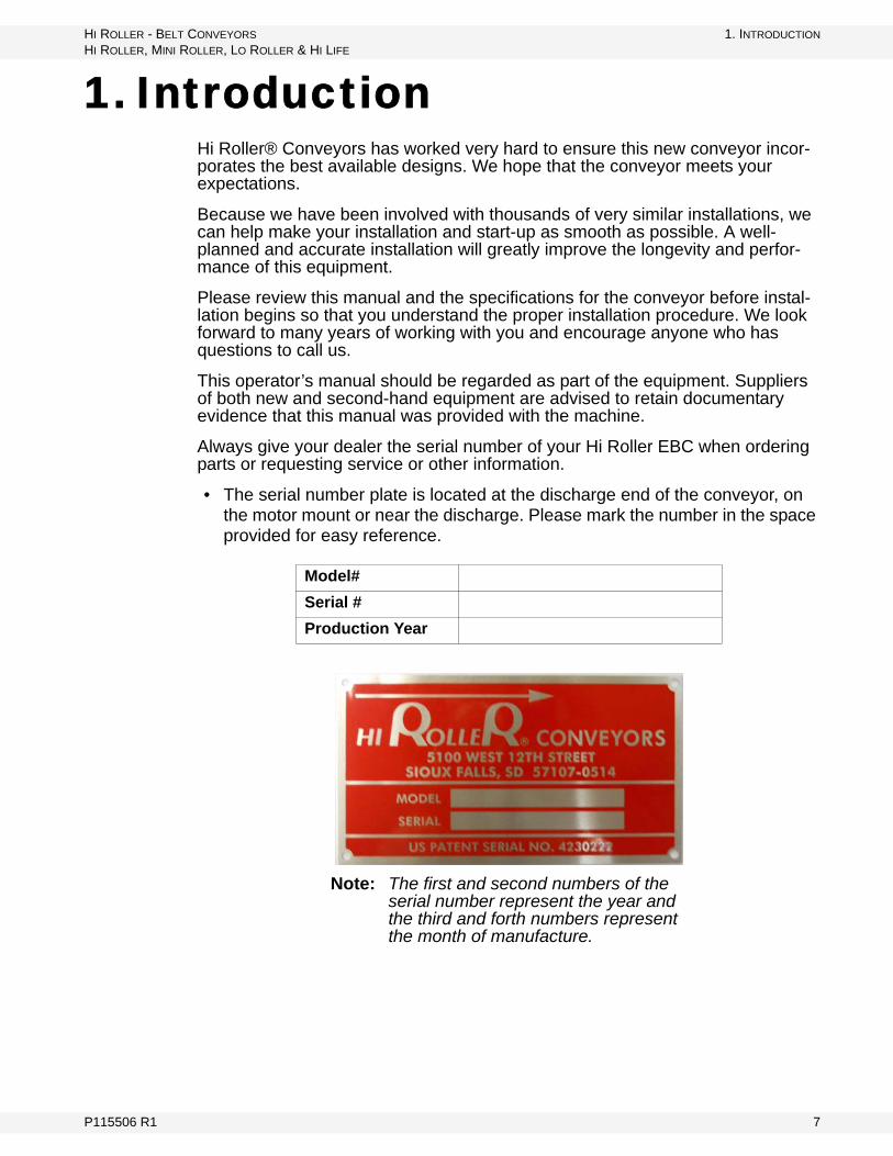
Always give your dealer the serial number of your Hi Roller EBC when ordering parts or requesting service or other information.
• The serial number plate is located at the discharge end of the conveyor, on the motor mount or near the discharge. Please mark the number in the space provided for easy reference.
Model#
Serial #
Production Year
Note: The first and second numbers of the serial number represent the year and the third and forth numbers represent the month of manufacture.
P115506 R1 7

1. INTRODUCTION HI ROLLER - BELT CONVEYORS
1.1. GENERAL DESCRIPTION HI ROLLER, MINI ROLLER, LO ROLLER & HI LIFE
1.1. GENERAL DESCRIPTION
Hi Roller® Conveyors are totally enclosed and self-cleaning belt conveyors. The conveyors are designed to convey granular, dry (non-sticking) bulk materials which are not excessively abrasive or corrosive; i.e. grains, oilseeds, absorbent clays, borax, fertilizers, etc.; while containing any fugitive dust and spillage from the conveyor. The conveyor is designed to be totally enclosed during normal operations with all covers, guards, inspection doors, etc. installed at all times of normal operations. Operating conditions are many above ground, storage reclaim tunnels, receiving pits, and above water levels; inside and outside of buildings, open & enclosed structures, and outdoors in most climates. There will a limited number of exposed people and operators as the conveyors will be typically installed in an industrial facility.
Conveyors are designed and manufactured to be a complete conveyor when properly installed by the customer or his representative. Complete Approval Drawings, Installation Drawings and Manuals are provided with each conveyor. The customer and his representatives must follow these documents to properly install each conveyor. The specifications provided with each conveyor must be followed.
When operating or maintaining the conveyor, never:
• change the size of the electric motor or pulleys to change the belt speed with-out written authorization from Hi-Roller.
• overfeed or overload the conveyor.• operate the conveyor empty for extended periods of time.• stand or walk on top of conveyor.• load off-center on the belt, idlers, and shafting.• use the conveyor to support other equipment.• weld anything to the equipment.• convey material other than dry granular material.
8 P115506 R1

HI ROLLER - BELT CONVEYORS 2. SAFETY
HI ROLLER, MINI ROLLER, LO ROLLER & HI LIFE 2.1. GENERAL SAFETY INFORMATION
2. Safety2.1. GENERAL SAFETY INFORMATION
The Safety Alert symbol identifies important safety messages on the product and in the manual. When you see this symbol, be alert to the possibility of personal injury or death. Follow the instructions in the safety messages.
Why is SAFETY important?
• Accidents disable and kill.• Accidents cost.• Accidents can be avoided.
SIGNAL WORDS: Note the use of the signal words DANGER, WARNING, CAUTION, and NOTICE with the safety messages. The appropriate signal word for each message has been selected using the definitions below as a guideline.
DANGER
Indicates an imminently hazardous situation that, if not avoided, will result in serious injury or death.
WARNING
Indicates a hazardous situation that, if not avoided, could result in serious injury or death.
CAUTION
Indicates a hazardous situation that, if not avoided, may result in minor or moderate injury.
NOTICE
Indicates a potentially hazardous situation that, if not avoided, may result in property damage.
P115506 R1 9

2. SAFETY HI ROLLER - BELT CONVEYORS
2.2. INSTALLATION SAFETY HI ROLLER, MINI ROLLER, LO ROLLER & HI LIFE
YOU are responsible for the SAFE use and maintenance of your equipment. YOU must ensure that you and anyone else who is going to work around the equipment understands all procedures and related SAFETY information contained in this manual.
Remember, YOU are the key to safety. Good safety practices not only protect you, but also the people around you. Make these practices a working part of your safety program.
Important: Below are general instructions that apply to all safety practices. Any instructions specific to a certain safety practice (e.g., Operational Safety), can be found in the appropriate section. Always read the complete instructional sections and not just these safety summaries before doing anything with the equipment.
• It is the equipment owner, operator, and maintenance personnel's responsi-bility to read and understand ALL safety instructions, safety decals, and man-uals and follow them when assembling, operating, or maintaining the equipment. All accidents can be avoided.
• Equipment owners must give instructions and review the information initially and annually with all personnel before allowing them to operate this product. Untrained users/operators expose themselves and bystanders to possible serious injury or death.
• Use this equipment for its intended purposes only.• Do not modify the equipment in any way without written permission from the
manufacturer. Unauthorized modification may impair the function and/or safety, and could affect the life of the equipment. Any unauthorized modifica-tion of the equipment voids the warranty.
• Do not allow any unauthorized person in the work area.
2.2. INSTALLATION SAFETY
1. Splice protections / wiper cleats must be properly installed to obtain proper reloading, to prevent product build-up on the return pan / bottom of the trunking, and to prevent wear on the belt splice.
2. Splice protectors / wiper cleats must be properly installed on both mechanical and vulcanized splices.
3. Never weld any item to any part of the covers, trunking, head section, or tail section.
4. Ensure that there is proper support for the head section, tail section, and trunking sections.
5. Clearances around the head section, tail section, and trunking are very important for proper operation and maintenance.
6. Trunking must be installed straight and level.
CAUTION
Loaders/inlets must be installed properly to achieve proper loading of the belt. Improper loading can cause damage to the conveyor components.
10 P115506 R1

HI ROLLER - BELT CONVEYORS 2. SAFETY
HI ROLLER, MINI ROLLER, LO ROLLER & HI LIFE 2.3. OPERATIONAL SAFETY
7. Inlet and discharge connections must be installed properly to maintain a free flow of material to and from the conveyor.
8. Conveyor belt must be installed properly.
9. The v-plow must be adjusted after the conveyor belt has been installed and properly tensioned.
2.3. OPERATIONAL SAFETY
1. Aspiration is very important to the proper operation of a Hi Roller Conveyor. Each conveyor should have adequate aspiration to maintain a slight negative pressure inside the enclosure.
2. Covers and guards must be bolted in place for safe operation.3. Conveyor covers can never be used as walkways.4. Untrained personnel must be kept outside of the work area.5. Keep body parts and clothing away from all moving parts.6. Lock out power before servicing any moving part.7. Hazard monitors must be installed and tested correctly to ensure proper
operation.8. A final inspection before start-up is extremely important! Complete the “Final
Checklist” on page 74 to ensure proper and safe operation of the conveyor.
2.4. MAINTENANCE SAFETY
1. Lock out power before performing any maintenance.2. Covers must be clamped in place to keep dust and weather contamination
out of the enclosure.3. Drive/reducers are shipped dry and must be filled with the proper oil/lubricant
(as specified by the manufacturer) before start-up.4. Bearings must be checked weekly to ensure proper operation. They must be
lubricated every 6 months, or with heavy usage, every 3 months. For more information, see the manufacturer’s schedule.
5. Conveying belt tension, tracking alignment, and drive belt tension must be checked weekly, or more often during seasonal weather changes.
6. To prevent damage to the gear reducer, ensure oil is filled to the level specified by the manufacturer.
7. Only qualified personnel should service electrical components.
WARNING
If conveyors are not installed properly, they will not operate at specified capacity and belt damage can occur.
Improperly installed belts can rub on sidewall and cause heat, creating a fire hazard.
P115506 R1 11

2. SAFETY HI ROLLER - BELT CONVEYORS
2.5. ELECTRIC MOTOR SAFETY HI ROLLER, MINI ROLLER, LO ROLLER & HI LIFE
8. Preventative maintenance on a regular basis is very important to the proper operation of a Hi Roller Conveyor.
9. Maintenance should only be performed under normal ambient lighting or daylight.
2.4.1. LOCKOUT AND TAGOUT PROCEDURES
To minimize possibility of serious injury or death to workers from hazardous energy release (for example, when restarting the equipment) and prevent worker deaths from all forms of hazardous energy release, follow all lockout and tagout procedures when installing and servicing equipment. Ensure that lockout and tagout procedures are adhered to. For example:
• De-energize, block, and dissipate all sources of hazardous energy.• Lock out and/or tag out all forms of hazardous energy.• Ensure that only 1 key exists for each assigned lock, and that you are the
only one that holds that key.• After verifying all energy sources are de-energized, service or installation
may be performed. • Ensure that all personnel are clear before turning on power to equipment.
For more information on occupational safety practices, contact your local health and safety organization.
2.5. ELECTRIC MOTOR SAFETY
• To prevent serious injury or death, only qualified personnel should service electrical components.
• Keep electrical components in good repair.• Ground electric motor before using.• Inspect drive belts before using. Replace if frayed or damaged.
2.6. SAFETY DECALS
• Keep safety decals clean and legible at all times.• Replace safety decals that are missing or have become illegible. See decal
location figures that follow.• Replaced parts must display the same decal(s) as the original part.• Safety decals are available from your distributor, dealer, or factory.
2.6.1. DECAL INSTALLATION
1. Decal area must be clean and dry, with a temperature above 50°F (10°C).2. Decide on the exact position before you remove the backing paper.
12 P115506 R1
HI ROLLER - BELT CONVEYORS 2. SAFETY
HI ROLLER, MINI ROLLER, LO ROLLER & HI LIFE 2.6. SAFETY DECALS
3. Align the decal over the specified area and carefully press the small portion with the exposed sticky backing in place.
4. Slowly peel back the remaining paper and carefully smooth the remaining portion of the decal in place.
5. Small air pockets can be pierced with a pin and smoothed out using the sign backing paper.
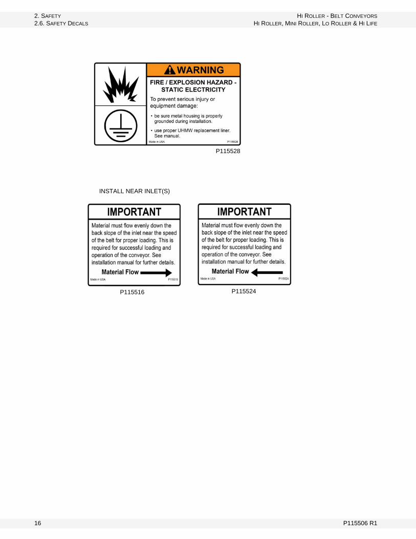
2.6.2. SAFETY DECAL LOCATIONS
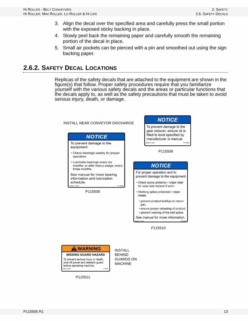
Replicas of the safety decals that are attached to the equipment are shown in the figure(s) that follow. Proper safety procedures require that you familiarize yourself with the various safety decals and the areas or particular functions that the decals apply to, as well as the safety precautions that must be taken to avoid serious injury, death, or damage.
INSTALL NEAR CONVEYOR DISCHARGE
P115508
P115509
P115510
INSTALL BEHIND GUARDS ON MACHINE
P115511
P115506 R1 13
2. SAFETY HI ROLLER - BELT CONVEYORS
2.6. SAFETY DECALS HI ROLLER, MINI ROLLER, LO ROLLER & HI LIFE
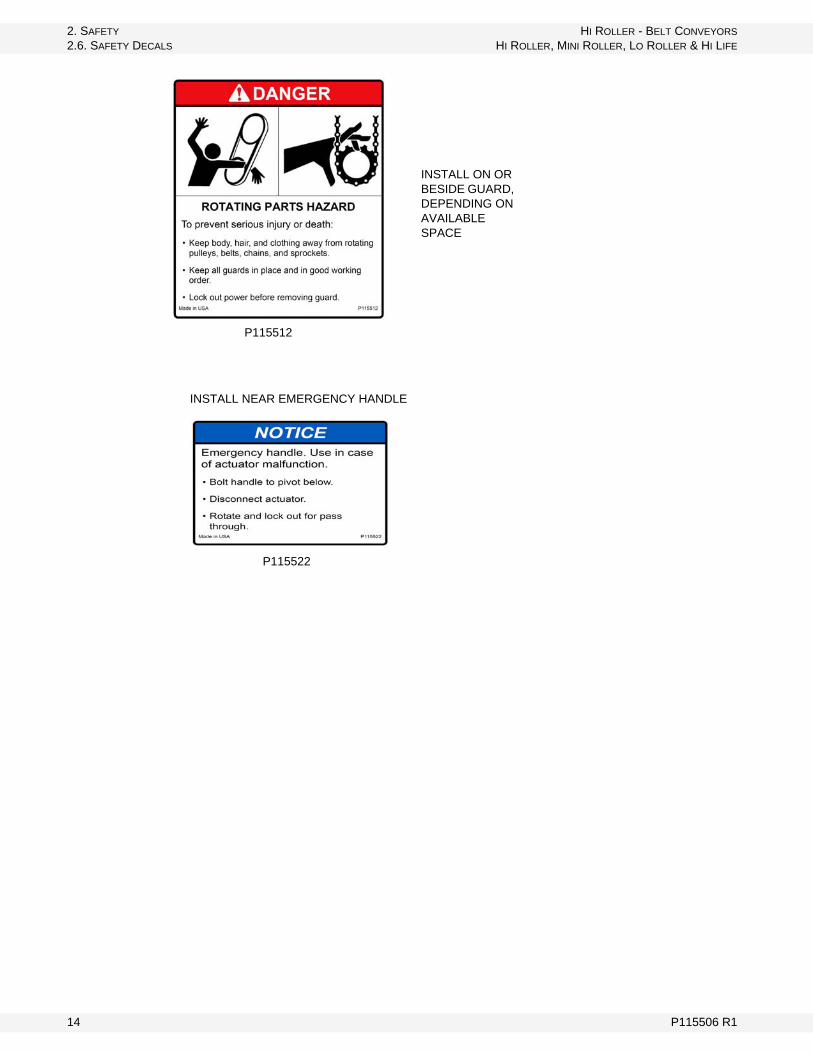
INSTALL ON OR BESIDE GUARD, DEPENDING ON AVAILABLE SPACE
P115512
P115522
INSTALL NEAR EMERGENCY HANDLE
14 P115506 R1

HI ROLLER - BELT CONVEYORS 2. SAFETY
HI ROLLER, MINI ROLLER, LO ROLLER & HI LIFE 2.6. SAFETY DECALS
GENERAL EQUIPMENT LABEL - INSTALL ON CONVEYOR SPOUT
P115513
INSTALL NEAR CONVEYOR DISCHARGE
P115514
INSTALL NEAR CONVEYOR ELECTRIC MOTOR
P115515
P115506 R1 15
2. SAFETY HI ROLLER - BELT CONVEYORS
2.6. SAFETY DECALS HI ROLLER, MINI ROLLER, LO ROLLER & HI LIFE
P115528
INSTALL NEAR INLET(S)
P115516 P115524
16 P115506 R1
HI ROLLER - BELT CONVEYORS 3. CONVEYOR COMPONENTS
HI ROLLER, MINI ROLLER, LO ROLLER & HI LIFE 3.1. OPERATOR ORIENTATION
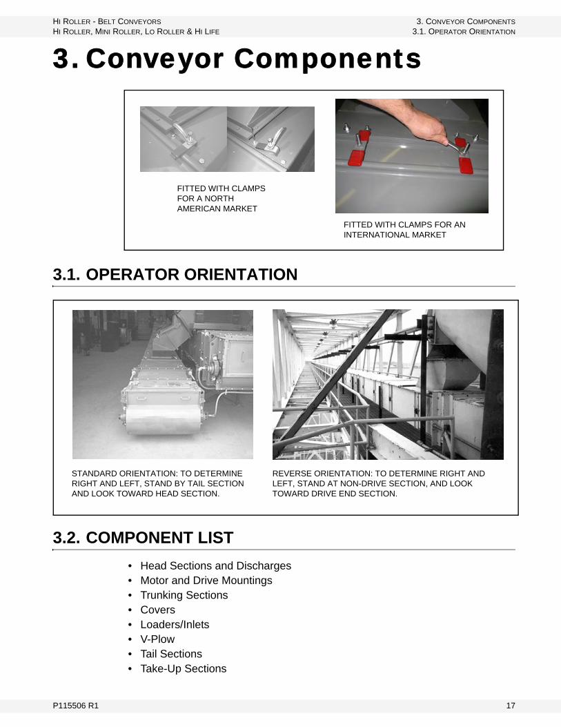
3. Conveyor Components
3.1. OPERATOR ORIENTATION
3.2. COMPONENT LIST
• Head Sections and Discharges • Motor and Drive Mountings • Trunking Sections• Covers• Loaders/Inlets• V-Plow• Tail Sections• Take-Up Sections
FITTED WITH CLAMPS FOR A NORTH AMERICAN MARKET
FITTED WITH CLAMPS FOR AN INTERNATIONAL MARKET
STANDARD ORIENTATION: TO DETERMINE RIGHT AND LEFT, STAND BY TAIL SECTION AND LOOK TOWARD HEAD SECTION.
REVERSE ORIENTATION: TO DETERMINE RIGHT AND LEFT, STAND AT NON-DRIVE SECTION, AND LOOK TOWARD DRIVE END SECTION.
P115506 R1 17

3. CONVEYOR COMPONENTS HI ROLLER - BELT CONVEYORS
3.2. COMPONENT LIST HI ROLLER, MINI ROLLER, LO ROLLER & HI LIFE
3.2.1. HEAD SECTIONS & DISCHARGES
• Head sections usually come with either a standard discharge (Figure 3.1) or snubber head discharge, which is bolted to the head section (Figure 3.2). Discharges usually have an inspection hatch at the top and a four-sided frame for transitions.
Figure 3.1 Standard Discharge
Figure 3.2 Snubber Head Section Discharge
3.2.2. MOTOR & DRIVE MOUNTINGS
Hi Roller mounts most factory supplied motors and reducers according to manufacturers specifications. Figure 3.3 shows a right-hand mounted drive.
18 P115506 R1
HI ROLLER - BELT CONVEYORS 3. CONVEYOR COMPONENTS
HI ROLLER, MINI ROLLER, LO ROLLER & HI LIFE 3.2. COMPONENT LIST
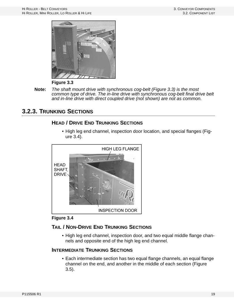
Figure 3.3
Note: The shaft mount drive with synchronous cog-belt (Figure 3.3) is the most common type of drive. The in-line drive with synchronous cog-belt final drive belt and in-line drive with direct coupled drive (not shown) are not as common.
3.2.3. TRUNKING SECTIONS
HEAD / DRIVE END TRUNKING SECTIONS
• High leg end channel, inspection door location, and special flanges (Fig-ure 3.4).
Figure 3.4
TAIL / NON-DRIVE END TRUNKING SECTIONS
• High leg end channel, inspection door, and two equal middle flange chan-nels and opposite end of the high leg end channel.
INTERMEDIATE TRUNKING SECTIONS
• Each intermediate section has two equal flange channels, an equal flange channel on the end, and another in the middle of each section (Figure 3.5).
P115506 R1 19

3. CONVEYOR COMPONENTS HI ROLLER - BELT CONVEYORS
3.2. COMPONENT LIST HI ROLLER, MINI ROLLER, LO ROLLER & HI LIFE
Figure 3.5
Note: For ease of assembly, sections are labeled and numbered starting with 1 on the tail section.
3.2.4. COVERS
Covers are made to fit over the width of the conveyor and 5’ of a section.
STANDARD 5’ COVERS
Figure 3.6
Note: Covers can be cut to length at the factory if ordered to specific lengths. (Contact Hi-Roller’s engineering department.)
INLET/LOADER
• Figure 3.7 shows a hold-down clamp (with a bend) near the inlet.
20 P115506 R1

HI ROLLER - BELT CONVEYORS 3. CONVEYOR COMPONENTS
HI ROLLER, MINI ROLLER, LO ROLLER & HI LIFE 3.2. COMPONENT LIST
Figure 3.7
INSPECTION DOORS
• For trunking, head, tail, and inlet/loader
Figure 3.8
P115506 R1 21

3. CONVEYOR COMPONENTS HI ROLLER - BELT CONVEYORS
3.2. COMPONENT LIST HI ROLLER, MINI ROLLER, LO ROLLER & HI LIFE
3.2.5. INLETS/LOADER
The loader must load in same direction that the belt travels, and material should move from spouts and gates at the same speed as the belt.
Figure 3.9 Standard Inlets - Flat Top w/ Matching Flange and Control Gate
Important: Off-center loading is harmful to the belt, idlers, and shafting, and will cause belt-alignment problems.
Custom loaders can be designed for specific overhead clearance considerations. Contact Hi Roller’s engineering department.
GATES
Gates control the flow of material down the back slope of the inlet when the gate opens (Figure 3.10).
Figure 3.10 Gate Orientation
SKIRTS
The skirts prevent side spillage of material and keep the load centered on the belt.
22 P115506 R1

HI ROLLER - BELT CONVEYORS 3. CONVEYOR COMPONENTS
HI ROLLER, MINI ROLLER, LO ROLLER & HI LIFE 3.2. COMPONENT LIST
Figure 3.11
3.2.6. V-PLOW
The v-plow is located just in front of the tail pulley. The v-plow:
• acts as a dam to hold back large amounts of spilled material that would plug the conveyor, and
• helps direct spilled material to the side of the tail section to be reloaded.
Figure 3.12 V-Plow
SHIPPED ATTACHED SHIPPED LOOSE
P115506 R1 23

3. CONVEYOR COMPONENTS HI ROLLER - BELT CONVEYORS
3.2. COMPONENT LIST HI ROLLER, MINI ROLLER, LO ROLLER & HI LIFE
3.2.7. TAIL SECTIONS
Figure 3.13 Standard Tail Section w/ Inner & Outer Box Take-Up
3.2.8. TAKE-UP SECTIONS
There is one take-up rod on each side of the take-up section on the centerline of the tail shaft bearings and they are used to tighten the belt (Figure 3.14).
Figure 3.14 Tail Take-Up Section w/ Rods and Leveling Rods
SPECIAL TAKE-UP SECTIONS
The take-up head section works in the same manner as a sliding box tail. The take-up rods located on the sides tighten the belt (Figure 3.15).
Figure 3.15 Head Take-Up Sections w/ Rods and Leveling Rods
The sliding plate take-up head section uses a sliding plate to mount the head pulley bearings. The conveyor belt is tightened with the take-up rods mounted directly behind the bearing mounting (Figure 3.16).
24 P115506 R1

HI ROLLER - BELT CONVEYORS 3. CONVEYOR COMPONENTS
HI ROLLER, MINI ROLLER, LO ROLLER & HI LIFE 3.2. COMPONENT LIST
Figure 3.16 Head Take-Up Sections w/ Sliding Bearing Mounts & Rods
P115506 R1 25

3. CONVEYOR COMPONENTS HI ROLLER - BELT CONVEYORS
3.2. COMPONENT LIST HI ROLLER, MINI ROLLER, LO ROLLER & HI LIFE
26 P115506 R1

HI ROLLER - BELT CONVEYORS 4. APPLICATION DESIGN CONSIDERATIONS
HI ROLLER, MINI ROLLER, LO ROLLER & HI LIFE 4.1. PRODUCT/CAPACITY CONSIDERATIONS
4. Application Design Considerations
This section is included to help you plan for the set-up and installation of your belt conveyor. Please review before beginning installation.
4.1. PRODUCT/CAPACITY CONSIDERATIONS
• Multiple Products: Make sure that the conveyor is designed and installed to handle all types and sizes of the materials you require.
• Bulk Density: pounds per cubic foot, pounds per bushels, metric tons per cubic meter, kg/cubic meter, etc.
• Abrasive/Corrosive/Sticky/Moist/Hot/Oily Materials: Design considera-tions must be reviewed with Hi Roller's engineering department.
• Capacity: Inclined conveyors of any type will not convey the same amount of material as a flat horizontal conveyor. Hi Roller's engineering department will calculate the capacity of a specific application.
• Belt Speed: The minimum for proper reloading is 350 fpm for granular mate-rials, and 400 fpm for powders/fine materials/meals.
4.1.1. ASPIRATION
Aspiration is designed to remove dust and not convey material.
GENERAL - DRY AMBIENT MATERIAL
• A 750 cfm system based on a 6” line at 4000 fpm is required to keep the lines clear. A pickup hood is also required so material is not picked up by the air (Figure 4.1).
Figure 4.1
P115506 R1 27

4. APPLICATION DESIGN CONSIDERATIONS HI ROLLER - BELT CONVEYORS
4.2. CLEARANCES HI ROLLER, MINI ROLLER, LO ROLLER & HI LIFE
HOT MOIST MATERIAL
• A 2356 cfm system based on two 6” lines at approximately 6000 fpm is required to keep the lines clean. The aspiration lines will have to be insulated to eliminate condensation on the inside of the lines. Pickup hoods will be required on the top of the conveyor so product dust is not picked up by the air (Figure 4.2).
• Tail section air intake: Approximately 10-20% of the total cfm. Fresh air will remove any buildup of moisture in the tail area.
• Product flow into the conveyor inlet/loader: Air flow should be eliminated as much as possible.
• Head section area air intakes: Balance of the total cfm - several intakes.Note: Many applications will also require that the conveyor be well insulated.
Figure 4.2
CONDENSATION PREVENTION
• Warm/moist air must not be allowed to vent through the conveyor because it will cause condensation to form on the inside of the conveyor enclosure as the dew point of the air is reached. Condensation or water can freeze inside the conveyor and cause substantial problems.
• Warm/hot moist materials will create warm moist air inside the conveyor enclosure and can cause extensive damage through condensation and freez-ing.
• Proper insulation: The outside skin of the conveyor enclosure may have to be insulated to eliminate the formation of condensation from cold outside temperatures.
• Vapor isolation: Warm and moist vapors can also cause condensation prob-lems. The conveyor enclosure must be isolated so that these vapors cannot circulate through the conveyor enclosure.
4.2. CLEARANCES
A number of clearances must be considered when planning the installation of the equipment. See figures below.
• idler bearing and shaft removal - clearance to the wall or structure• idler removal - clearance above the conveyor cover• tail shaft and bearings - much wider than standard trunking sections
28 P115506 R1
HI ROLLER - BELT CONVEYORS 4. APPLICATION DESIGN CONSIDERATIONS
HI ROLLER, MINI ROLLER, LO ROLLER & HI LIFE 4.3. DISCHARGE CONSIDERATIONS
• take-up section - clearance to access take-up rods• head section - much wider than standard trunking sections• motor and drive - depending on type, much wider than head section• tripper sections - much wider than standard trunking sections• bottom clearances for cleaning and bottom removal• inspection doors and top cover removal• tail cover and inspection door removal
4.3. DISCHARGE CONSIDERATIONS
• Spouting angles: Materials flow differently in spouting. The proper angle must be maintained so that the material will freely flow in the spout.
• Spouting sized properly: Flow characteristics are different for each type of material. Properly sized spouting must be installed to handle the capacity of the discharge flow from the conveyor.
4.4. INCLINES
• Gradual: Hi Roller Conveyors can be installed with a gradual up-bend. This is the lowest cost, horsepower, and maintenance option. Hi Roller's engineering department must complete design calculations to determine the amount of gradual up-bend that can be installed on a specific application.
• Sharp up-bends: Hi Roller Conveyors can be installed with a sharp up-bend section. This is the highest cost, horsepower, and maintenance option. Hi Roller's engineering department must complete design calculations to deter-mine the amount of increased horsepower and cost of this option for a spe-cific application.
• Horsepower: Inclined conveyors of any type require additional horsepower. A straight, gradual or sharp up-bend inclined conveyor will require additional horsepower to simply lift the material. This additional horsepower will be cal-culated by Hi Roller's engineering department.
• Capacity: Inclined conveyors of any type will not convey the same amount of material as a flat horizontal conveyor. Hi Roller's engineering department will calculate the capacity of a specific application.
4.5. TRUNKING INSTALLATION
Important: Trunking MUST be installed straight.
Check trunking installation with laser, transit, or wire line to ensure it is installed in a straight line. Trunking that is not installed straight will cause belt tracking problems.
P115506 R1 29

4. APPLICATION DESIGN CONSIDERATIONS HI ROLLER - BELT CONVEYORS
4.6. LOADING CONSIDERATIONS HI ROLLER, MINI ROLLER, LO ROLLER & HI LIFE
Figure 4.3
4.6. LOADING CONSIDERATIONS
The loader must be placed on the conveyor trunking so it will load in the same direction of belt travel. It is at the loading point that the conveyor belt receives major abrasion and almost all of its impact. The ideal condition is to have the material pass from spout to belt at the same speed and direction of travel as the belt, with a minimum amount of impact and centered on the belt.
Note: Off-center loading is harmful to the belt, idlers, and shafting. An off-center load will cause belt alignment problems.
Please consider:
• control gate orientation• control flows from all spouts• side loading problems• high velocity and turbulent flows• straight down flow problems• poor loading leading to belt tracking problems• belt speed vs. proper loading• level/even loading problems
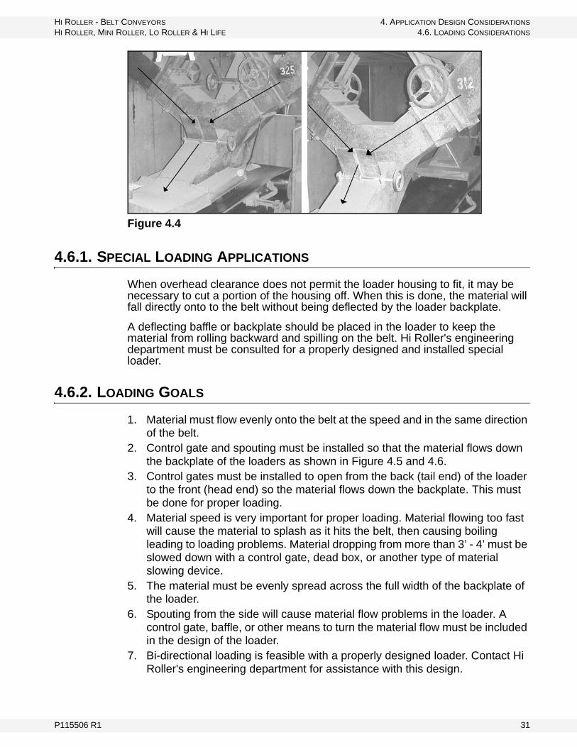
Y-spouts can cause side loading problems where the belt gets pushed sideways, and leads to tracking problems. Improper loading will then reduce the capacity of the belt.
Figure 4.4 illustrates typical side loading problems created by a Y-spout.
30 P115506 R1
HI ROLLER - BELT CONVEYORS 4. APPLICATION DESIGN CONSIDERATIONS
HI ROLLER, MINI ROLLER, LO ROLLER & HI LIFE 4.6. LOADING CONSIDERATIONS
Figure 4.4
4.6.1. SPECIAL LOADING APPLICATIONS
When overhead clearance does not permit the loader housing to fit, it may be necessary to cut a portion of the housing off. When this is done, the material will fall directly onto to the belt without being deflected by the loader backplate.
A deflecting baffle or backplate should be placed in the loader to keep the material from rolling backward and spilling on the belt. Hi Roller's engineering department must be consulted for a properly designed and installed special loader.
4.6.2. LOADING GOALS
1. Material must flow evenly onto the belt at the speed and in the same direction of the belt.
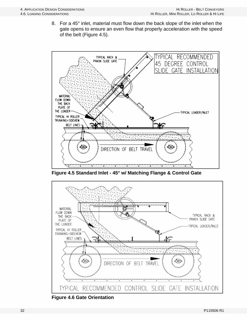
2. Control gate and spouting must be installed so that the material flows down the backplate of the loaders as shown in Figure 4.5 and 4.6.
3. Control gates must be installed to open from the back (tail end) of the loader to the front (head end) so the material flows down the backplate. This must be done for proper loading.
4. Material speed is very important for proper loading. Material flowing too fast will cause the material to splash as it hits the belt, then causing boiling leading to loading problems. Material dropping from more than 3’ - 4’ must be slowed down with a control gate, dead box, or another type of material slowing device.
5. The material must be evenly spread across the full width of the backplate of the loader.
6. Spouting from the side will cause material flow problems in the loader. A control gate, baffle, or other means to turn the material flow must be included in the design of the loader.
7. Bi-directional loading is feasible with a properly designed loader. Contact Hi Roller's engineering department for assistance with this design.
P115506 R1 31
4. APPLICATION DESIGN CONSIDERATIONS HI ROLLER - BELT CONVEYORS
4.6. LOADING CONSIDERATIONS HI ROLLER, MINI ROLLER, LO ROLLER & HI LIFE
8. For a 45° inlet, material must flow down the back slope of the inlet when the gate opens to ensure an even flow that properly acceleration with the speed of the belt (Figure 4.5).
Figure 4.5 Standard Inlet - 45° w/ Matching Flange & Control Gate
Figure 4.6 Gate Orientation
32 P115506 R1
HI ROLLER - BELT CONVEYORS 4. APPLICATION DESIGN CONSIDERATIONS
HI ROLLER, MINI ROLLER, LO ROLLER & HI LIFE 4.7. SPLICES
4.7. SPLICES
• Mechanical: Flexco splices are standard on Hi Roller Conveyors. Different types of Flexco splices are recommended for each application.
• Vulcanized: Hi Roller recommends that a mechanical splice is used during the first year of operation. The belt should be stretched and stabilized before a permanent vulcanized splice is installed because of the limited length of the take-up section of the conveyor.
4.8. SUPPORTS
• Supports must be installed at least every 20’ of the length of the conveyor.• Support legs or hangers should always be bolted to the trunking vertical or
bottom flanges. Supports should never be welded to the trunking sides.
4.9. GROUNDING
Conveyors should be grounded by a qualified electrician according to the local codes and regulations.
P115506 R1 33

4. APPLICATION DESIGN CONSIDERATIONS HI ROLLER - BELT CONVEYORS
4.9. GROUNDING HI ROLLER, MINI ROLLER, LO ROLLER & HI LIFE
34 P115506 R1
HI ROLLER - BELT CONVEYORS 5. INSTALLATION
HI ROLLER, MINI ROLLER, LO ROLLER & HI LIFE 5.1. PRE-INSTALLATION
5. Installation
Proper installation of the Hi Roller Conveyor is very important. By following the basic rules and planning for installation, start-up problems will be reduced dramatically.
• Never weld any item to a part of the cover, trunking, head or tail sections.• Always properly support the head, tail, and trunking sections.
5.1. PRE-INSTALLATION
1. Review construction and approval drawings, specifications, etc.2. Check construction print for exact conveyor location. Conveyor must be
assembled as indicated on your construction prints.• A drawing has been included for your conveyor showing the location of
each numbered section.3. Review general conveyor information.4. Refer information included in the appendix.5. Read ALL of the installation instructions before beginning.6. Check hardware package and shipping list - report any shortages.7. Prepare for assembly by checking the head end trunking section and tail end
trunking section for position of the end channels. • Bolts, hex nuts, and lock washers have been included in the hardware
package. All "bolt-together" points should be caulked with silicone sealant to keep the dust in and weather out.
8. Check that you will have adequate clearances around the conveyor. Clearances around the head section, tail section, and trunking are very important for proper operation and maintenance.
5.2. HEAD END & TAIL END TRUNKING INSTALLATION
5.2.1. HEAD SECTION MOUNTING
The head section must be properly supported so there is no vertical or horizontal movement.
The support structure should be attached to the bolted connections of the head section on the bottom or top depending on the design of the motor mount. Also, a bolted connection can be attached to the bearing mounting vertical plate.
Note: Do not mount head section to the discharge hood/overshot! The discharge hood/overshot is NOT a structural part of the conveyor.
WARNING Before continuing, ensure you have read and understand the relevant information in the safety section. Safety information is provided to help prevent serious injury, death, or property damage.
P115506 R2 35
5. INSTALLATION HI ROLLER - BELT CONVEYORS
5.2. HEAD END & TAIL END TRUNKING INSTALLATION HI ROLLER, MINI ROLLER, LO ROLLER & HI LIFE
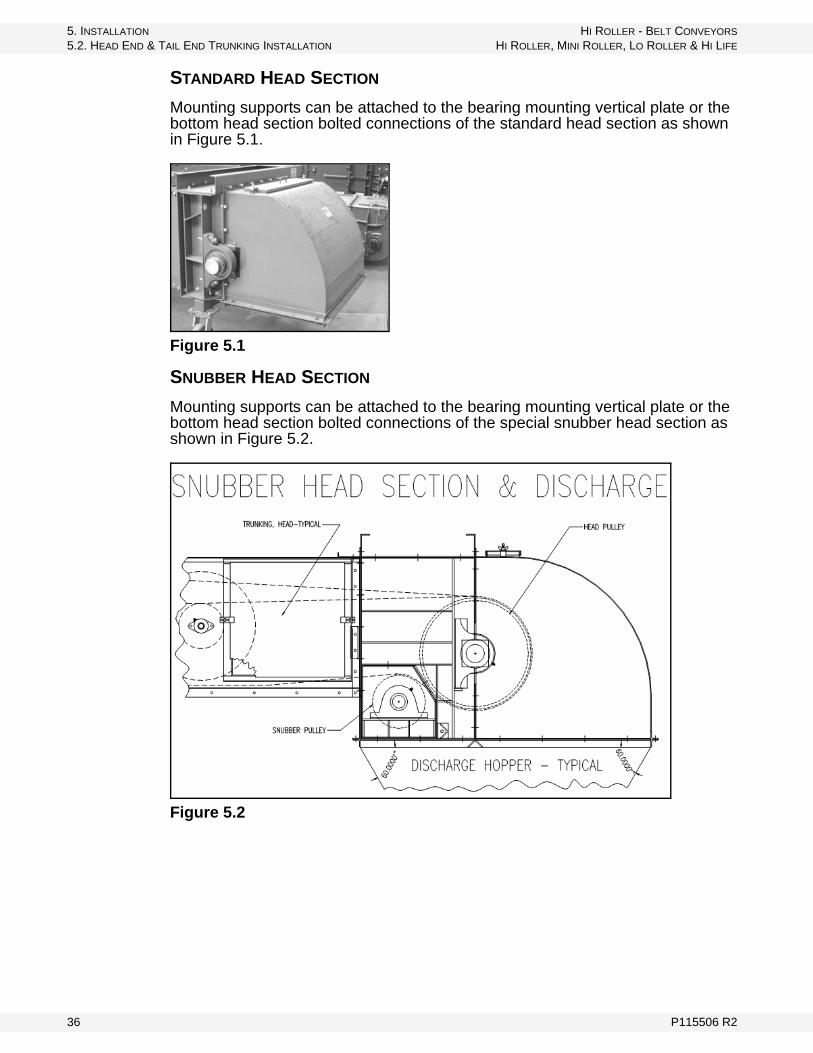
STANDARD HEAD SECTION
Mounting supports can be attached to the bearing mounting vertical plate or the bottom head section bolted connections of the standard head section as shown in Figure 5.1.
Figure 5.1
SNUBBER HEAD SECTION
Mounting supports can be attached to the bearing mounting vertical plate or the bottom head section bolted connections of the special snubber head section as shown in Figure 5.2.
Figure 5.2
36 P115506 R2
HI ROLLER - BELT CONVEYORS 5. INSTALLATION
HI ROLLER, MINI ROLLER, LO ROLLER & HI LIFE 5.2. HEAD END & TAIL END TRUNKING INSTALLATION
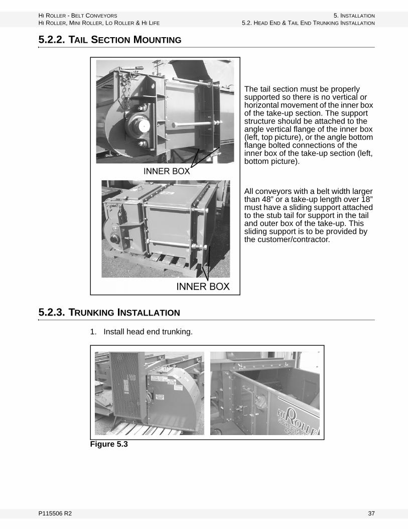
5.2.2. TAIL SECTION MOUNTING
The tail section must be properly supported so there is no vertical or horizontal movement of the inner box of the take-up section. The support structure should be attached to the angle vertical flange of the inner box (left, top picture), or the angle bottom flange bolted connections of the inner box of the take-up section (left, bottom picture).
All conveyors with a belt width larger than 48” or a take-up length over 18” must have a sliding support attached to the stub tail for support in the tail and outer box of the take-up. This sliding support is to be provided by the customer/contractor.
5.2.3. TRUNKING INSTALLATION
1. Install head end trunking.
Figure 5.3
P115506 R2 37

5. INSTALLATION HI ROLLER - BELT CONVEYORS
5.2. HEAD END & TAIL END TRUNKING INSTALLATION HI ROLLER, MINI ROLLER, LO ROLLER & HI LIFE
Figure 5.4
2. Take note of the trunking identification/numbering system; use this to help you assemble the trunking in the correct order (Figure 5.5).
Figure 5.5
3. Caulk and seal all bolt-together flanges (Figure 5.6).
Figure 5.6
4. Check and double-check with a laser, transit, or wire line that trunking is installed straight and level .
5. Maintain clearances and install tail end trunking section.
NOTICE
Trunking must be installed straight and level with a tolerance less than +/- 1/8” over the entire length of the conveyor.
38 P115506 R2
HI ROLLER - BELT CONVEYORS 5. INSTALLATION
HI ROLLER, MINI ROLLER, LO ROLLER & HI LIFE 5.2. HEAD END & TAIL END TRUNKING INSTALLATION
6. Support legs, feet, and support hangers. Trunking sections must be well supported every 20’ of the length of the conveyor.
Important: Support structures and legs must never be welded to the trunking sidewalls or flanges. All connections must be bolted to the trunking or trunking flanges.
5.2.4. TAIL SECTION BACK COVER REMOVAL & INSTALLATION
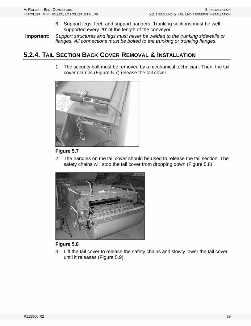
1. The security bolt must be removed by a mechanical technician. Then, the tail cover clamps (Figure 5.7) release the tail cover.
Figure 5.7
2. The handles on the tail cover should be used to release the tail section. The safety chains will stop the tail cover from dropping down (Figure 5.8).
Figure 5.8
3. Lift the tail cover to release the safety chains and slowly lower the tail cover until it releases (Figure 5.9).
P115506 R2 39

5. INSTALLATION HI ROLLER - BELT CONVEYORS
5.3. INLET/LOADER INSTALLATION HI ROLLER, MINI ROLLER, LO ROLLER & HI LIFE
Figure 5.9
4. The installation is the reverse of the removal. The security bolt must be removed by a mechanical technician.
5.3. INLET/LOADER INSTALLATION
The loader must be placed on the conveyor trunking so it will load in the same direction as the belt travels. The loading point of a belt conveyor is the critical point. Here, the conveyor belt receives major abrasion and almost all of its impact. Ideally, material will pass from spout to belt at the same speed and direction of travel as the belt, with a minimum amount of impact and centered on the belt.
Off-center loading is harmful to the belt, idlers, and shafting, and will cause belt alignment problems.
Figure 5.10 Standard Inlets - Flat Top w/ Matching Flange and Control Gate
NOTICE
Loaders/inlets must be installed properly to achieve proper loading of the belt.
Improper loading can cause damage to the conveyor components.
40 P115506 R2
HI ROLLER - BELT CONVEYORS 5. INSTALLATION
HI ROLLER, MINI ROLLER, LO ROLLER & HI LIFE 5.3. INLET/LOADER INSTALLATION
5.3.1. SKIRT INSTALLATION
The skirts prevent side spillage of material and keep the load centered on the belt. Generally, the maximum distance between skirt boards is two-thirds the width of a troughed belt.
The skirt lengths are designed to stop side spillage. The material should also be at rest on the belt before it reaches the end of the skirt. If the material is still tumbling as it passes the skirt end, the skirts should be lengthened or the speed reduced to match the speed of the belt.
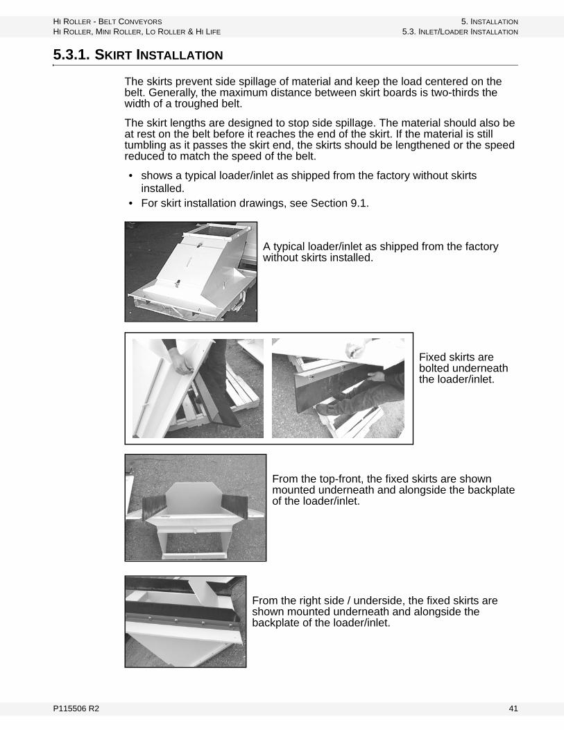
• shows a typical loader/inlet as shipped from the factory without skirts installed.
• For skirt installation drawings, see Section 9.1.
A typical loader/inlet as shipped from the factory without skirts installed.
Fixed skirts are bolted underneath the loader/inlet.
From the top-front, the fixed skirts are shown mounted underneath and alongside the backplate of the loader/inlet.
From the right side / underside, the fixed skirts are shown mounted underneath and alongside the backplate of the loader/inlet.
P115506 R2 41
5. INSTALLATION HI ROLLER - BELT CONVEYORS
5.4. BELT INSTALLATION HI ROLLER, MINI ROLLER, LO ROLLER & HI LIFE
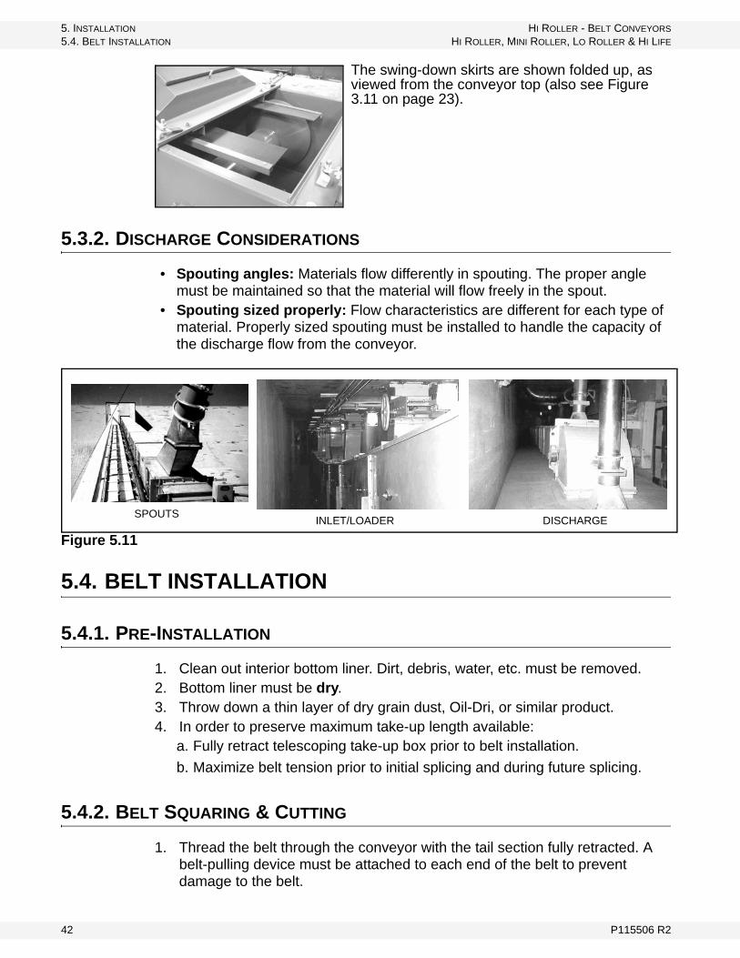
The swing-down skirts are shown folded up, as viewed from the conveyor top (also see Figure 3.11 on page 23).
5.3.2. DISCHARGE CONSIDERATIONS
• Spouting angles: Materials flow differently in spouting. The proper angle must be maintained so that the material will flow freely in the spout.
• Spouting sized properly: Flow characteristics are different for each type of material. Properly sized spouting must be installed to handle the capacity of the discharge flow from the conveyor.
Figure 5.11
5.4. BELT INSTALLATION
5.4.1. PRE-INSTALLATION
1. Clean out interior bottom liner. Dirt, debris, water, etc. must be removed.2. Bottom liner must be dry.3. Throw down a thin layer of dry grain dust, Oil-Dri, or similar product.4. In order to preserve maximum take-up length available:
a. Fully retract telescoping take-up box prior to belt installation.
b. Maximize belt tension prior to initial splicing and during future splicing.
5.4.2. BELT SQUARING & CUTTING
1. Thread the belt through the conveyor with the tail section fully retracted. A belt-pulling device must be attached to each end of the belt to prevent damage to the belt.
SPOUTSINLET/LOADER DISCHARGE
42 P115506 R2
HI ROLLER - BELT CONVEYORS 5. INSTALLATION
HI ROLLER, MINI ROLLER, LO ROLLER & HI LIFE 5.4. BELT INSTALLATION
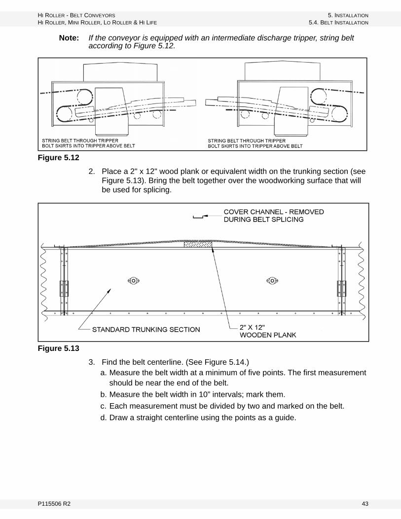
Note: If the conveyor is equipped with an intermediate discharge tripper, string belt according to Figure 5.12.
Figure 5.12
2. Place a 2" x 12" wood plank or equivalent width on the trunking section (see Figure 5.13). Bring the belt together over the woodworking surface that will be used for splicing.
Figure 5.13
3. Find the belt centerline. (See Figure 5.14.) a. Measure the belt width at a minimum of five points. The first measurement
should be near the end of the belt.
b. Measure the belt width in 10” intervals; mark them.
c. Each measurement must be divided by two and marked on the belt.
d. Draw a straight centerline using the points as a guide.
P115506 R2 43

5. INSTALLATION HI ROLLER - BELT CONVEYORS
5.4. BELT INSTALLATION HI ROLLER, MINI ROLLER, LO ROLLER & HI LIFE
Figure 5.14
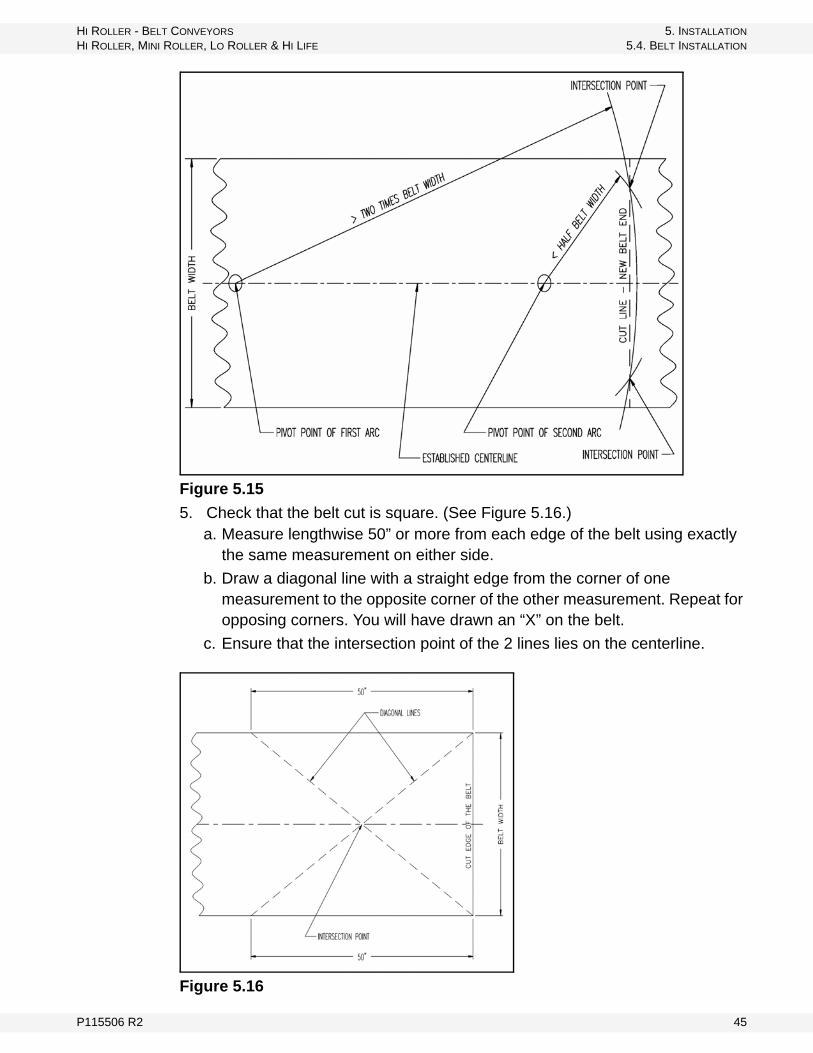
4. Square the belt ends. (See Figure 5.15.)a. Use a double arc to establish a cut line on the belt. Using the centerline
drawn on the belt, pick a point on the line at least two times the belt width.
b. Strike an arc across the width of the belt at the belt end from this point. A nail may be used as a pivot point with good wire or cord attached to it. Use a marker or chalk to mark the arc.
c. A second set of arcs must be struck with the pivot point of the arcs on the centerline with a radius of slightly less than half the belt width.
d. A cut line is drawn where the 2 arcs intersect each other.
44 P115506 R2
HI ROLLER - BELT CONVEYORS 5. INSTALLATION
HI ROLLER, MINI ROLLER, LO ROLLER & HI LIFE 5.4. BELT INSTALLATION
Figure 5.15
5. Check that the belt cut is square. (See Figure 5.16.)a. Measure lengthwise 50” or more from each edge of the belt using exactly
the same measurement on either side.
b. Draw a diagonal line with a straight edge from the corner of one measurement to the opposite corner of the other measurement. Repeat for opposing corners. You will have drawn an “X” on the belt.
c. Ensure that the intersection point of the 2 lines lies on the centerline.
Figure 5.16
P115506 R2 45
5. INSTALLATION HI ROLLER - BELT CONVEYORS
5.4. BELT INSTALLATION HI ROLLER, MINI ROLLER, LO ROLLER & HI LIFE
6. Splice the belt following the manufacturer’s instructions.
5.4.3. SPLICE PROTECTOR / WIPER CLEATS
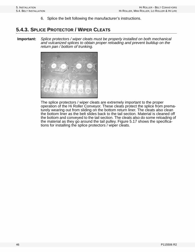
Important: Splice protectors / wiper cleats must be properly installed on both mechanical and vulcanized splices to obtain proper reloading and prevent buildup on the return pan / bottom of trunking.
The splice protectors / wiper cleats are extremely important to the proper operation of the Hi Roller Conveyor. These cleats protect the splice from prema-turely wearing out from sliding on the bottom return liner. The cleats also clean the bottom liner as the belt slides back to the tail section. Material is cleaned off the bottom and conveyed to the tail section. The cleats also do some reloading of the material as they go around the tail pulley. Figure 5.17 shows the specifica-tions for installing the splice protectors / wiper cleats.
46 P115506 R2

HI ROLLER - BELT CONVEYORS 5. INSTALLATION
HI ROLLER, MINI ROLLER, LO ROLLER & HI LIFE 5.4. BELT INSTALLATION
Figure 5.17 Specifications
Table 5.1 Belt Splice Protector / Wiper Cleat Spacing
Belt Width
No. Pads ECFT Bolts Dim. A Dim. B
12” 3 6 3/16” 3/16”
16” 4 8 1/4” 3/16”
18” 4 8 3/4” 1/2”
20” 5 10 1/4” 3/16”
22” 5 10 5/8” 1/2”
24” 6 12 1/4” 3/16”
26” 6 12 1/2” 1/2”
30” 7 14 3/8” 1/2”
36” 9 18 1/8” 1/4”
42” 10 20 9/16” 3/8”
48” 12 24 1/8” 1/4”
54” 13 26 3/8” 3/8”
60” 14 28 1/2” 1/2”
P115506 R2 47
5. INSTALLATION HI ROLLER - BELT CONVEYORS
5.4. BELT INSTALLATION HI ROLLER, MINI ROLLER, LO ROLLER & HI LIFE
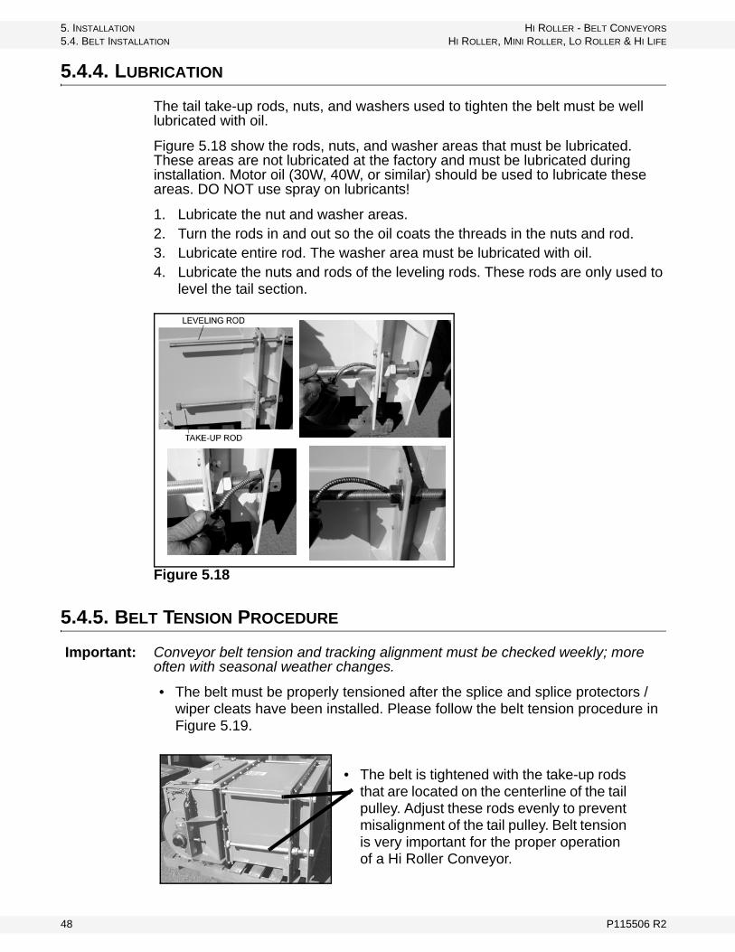
5.4.4. LUBRICATION
The tail take-up rods, nuts, and washers used to tighten the belt must be well lubricated with oil.
Figure 5.18 show the rods, nuts, and washer areas that must be lubricated. These areas are not lubricated at the factory and must be lubricated during installation. Motor oil (30W, 40W, or similar) should be used to lubricate these areas. DO NOT use spray on lubricants!
1. Lubricate the nut and washer areas.2. Turn the rods in and out so the oil coats the threads in the nuts and rod.3. Lubricate entire rod. The washer area must be lubricated with oil.4. Lubricate the nuts and rods of the leveling rods. These rods are only used to
level the tail section.
Figure 5.18
5.4.5. BELT TENSION PROCEDURE
Important: Conveyor belt tension and tracking alignment must be checked weekly; more often with seasonal weather changes.
• The belt must be properly tensioned after the splice and splice protectors /wiper cleats have been installed. Please follow the belt tension procedure in Figure 5.19.
• The belt is tightened with the take-up rods that are located on the centerline of the tail pulley. Adjust these rods evenly to prevent misalignment of the tail pulley. Belt tension is very important for the proper operation of a Hi Roller Conveyor.
48 P115506 R2

HI ROLLER - BELT CONVEYORS 5. INSTALLATION
HI ROLLER, MINI ROLLER, LO ROLLER & HI LIFE 5.4. BELT INSTALLATION
• The belt must be tightened to the proper specifications. Belt tension must be checked daily for the first several days, and then weekly until the belt has sta-bilized and adjustments are not required. This may happen quickly or over the space of a couple of months.
Note: Take-up rods are designed for belt tightening only, although slight (1/8”) tracking adjustments can be made with them. More drastic tracking should be done by adding or removing shims from under the pillow block tail bearings.
The top leveling rods must only be used to level the tail section. For proper use of the tensioning and leveling rods, see Section 5.5.
TO PERFORM BELT TENSION PROCEDURE (FIGURE 5.19):
Materials needed:
• Model 26 and larger: three 2” x 4” boards just shorter than the trunking width. Models 22 and smaller: three 1” x 4” boards
• 1 set of 200 lb weights• 1 ruler / tape measure
1. Belt tension can be measured between any 2 idlers, but it is best to be at least 2 to 3 idlers away from the head and tail sections.
2. Remove the covers from the test area.3. Place one board over each idler under the belt with the inside edges
centered over the idler shafts.4. Measure the distance between the nearest edges of the support boards. This
span should be 5’.5. Measure the distance “X” from the top of the trunking to the unweighted belt.6. Place the third board centered between the support boards.7. Place 200 lb weight on the center board.8. Measure the distance “Y” from the top of the trunking to the weighted belt.9. Compute belt deflection = “Y” - “X”10. Adjust belt tension equally on both sides of the take-up until the belt
deflection is within the given range listed on the pedigree page insert. The minimum amount of belt tension should provide good operation. However, under certain conditions the head pulley may slip. In those instances, add tension until the slippage stops, then measure the belt defelction to confirm that it is still within the suggested range.
Alternate method for short or limited access conveyors:
1. Locate 2 idlers that are 60” apart. Remove cover.2. Measure the distance “X” from the top of the trunking to either side of the belt.3. Cut a board the same length as the center horizontal tube of the idler. Place
this board across the belt in the center of the span and center of the belt. Add 200 lb weight.
4. Measure the distance “Y” from the top of the trunking to the same side of the belt as previously measured.
5. Continue from step 9 above.
P115506 R2 49

5. INSTALLATION HI ROLLER - BELT CONVEYORS
5.4. BELT INSTALLATION HI ROLLER, MINI ROLLER, LO ROLLER & HI LIFE
Figure 5.19
50 P115506 R2
HI ROLLER - BELT CONVEYORS 5. INSTALLATION
HI ROLLER, MINI ROLLER, LO ROLLER & HI LIFE 5.4. BELT INSTALLATION
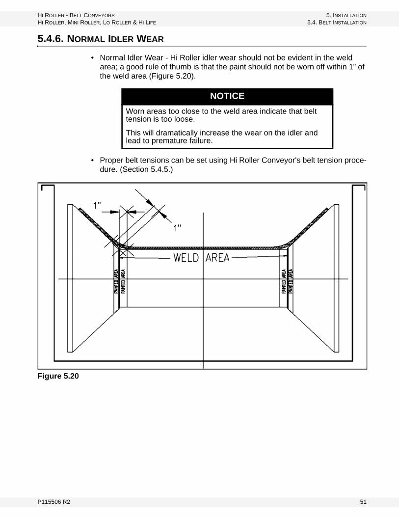
5.4.6. NORMAL IDLER WEAR
• Normal Idler Wear - Hi Roller idler wear should not be evident in the weld area; a good rule of thumb is that the paint should not be worn off within 1” of the weld area (Figure 5.20).
• Proper belt tensions can be set using Hi Roller Conveyor's belt tension proce-dure. (Section 5.4.5.)
Figure 5.20
NOTICE
Worn areas too close to the weld area indicate that belt tension is too loose.
This will dramatically increase the wear on the idler and lead to premature failure.
P115506 R2 51

5. INSTALLATION HI ROLLER - BELT CONVEYORS
5.5. LEVELING TAIL TAKE-UP SECTION HI ROLLER, MINI ROLLER, LO ROLLER & HI LIFE
5.5. LEVELING TAIL TAKE-UP SECTION
Important: Take-up rods, nuts, and washer areas must be properly lubricated.
Level tail with leveling rod.
Figure 5.21
5.6. V-PLOW ADJUSTMENT
Important: The v-plow must be adjusted after the conveyor belt has been installed and properly tensioned.
The v-plow is NOT set at the factory. It must be adjusted so that the UHMW (black plastic) blade is 1/4" - 1/2" above the conveyor belt. The v-plow may have to be set at an angle to follow the belt line as it rises to the tail pulley.
• After adjustment, watch to make sure that the splice protector / wiper cleats do not hit the v-plow blade when they pass under the v-plow.
The v-plow shown in Figure 5.22 is installed in the tail section before the belt has been installed.
Figure 5.22
52 P115506 R2

HI ROLLER - BELT CONVEYORS 5. INSTALLATION
HI ROLLER, MINI ROLLER, LO ROLLER & HI LIFE 5.7. COVER INSTALLATION
There are two v-plow adjustment bolts on each side of the tail section. Loosen all bolts, adjust v-plow, and tighten to set (Figure 5.23).
Figure 5.23
5.7. COVER INSTALLATION
The conveyor must be completely installed with all inlets/loaders in the proper locations before installing covers.
5.7.1. MADE-TO-LENGTH COVERS
See Figure 5.24, 5.25, and 5.26.
Measure from the centerline of the channel flange to inlet flange as shown in Figure 5.25. This is the measurement that is required by the factory to manufac-turer made-to-length covers.
All of the covers that are going to be made-to-length must be measured using the same procedure; the location of each of these covers should be noted.
These measurements need to be called in or sent to the Hi Roller engineering department.
Figure 5.24
P115506 R2 53
5. INSTALLATION HI ROLLER - BELT CONVEYORS
5.7. COVER INSTALLATION HI ROLLER, MINI ROLLER, LO ROLLER & HI LIFE
Figure 5.25
Figure 5.26
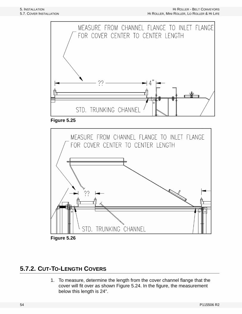
5.7.2. CUT-TO-LENGTH COVERS
1. To measure, determine the length from the cover channel flange that the cover will fit over as shown Figure 5.24. In the figure, the measurement below this length is 24".
54 P115506 R2
HI ROLLER - BELT CONVEYORS 5. INSTALLATION
HI ROLLER, MINI ROLLER, LO ROLLER & HI LIFE 5.7. COVER INSTALLATION
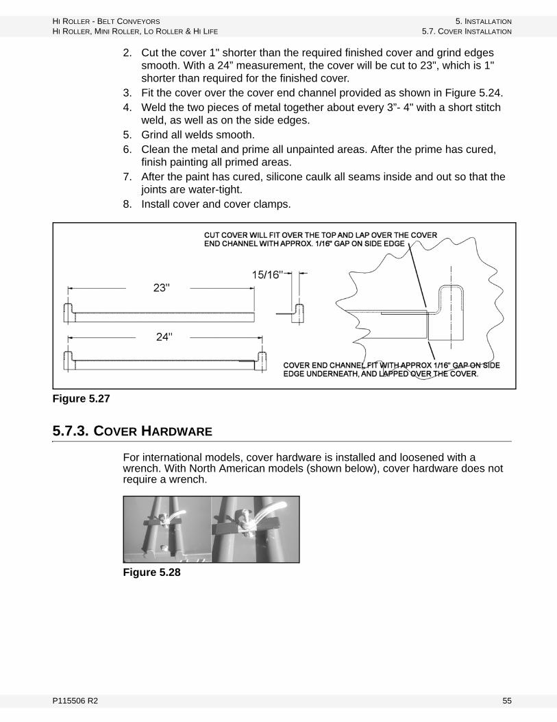
2. Cut the cover 1" shorter than the required finished cover and grind edges smooth. With a 24” measurement, the cover will be cut to 23", which is 1" shorter than required for the finished cover.
3. Fit the cover over the cover end channel provided as shown in Figure 5.24.4. Weld the two pieces of metal together about every 3”- 4" with a short stitch
weld, as well as on the side edges.5. Grind all welds smooth.6. Clean the metal and prime all unpainted areas. After the prime has cured,
finish painting all primed areas.7. After the paint has cured, silicone caulk all seams inside and out so that the
joints are water-tight.8. Install cover and cover clamps.
Figure 5.27
5.7.3. COVER HARDWARE
For international models, cover hardware is installed and loosened with a wrench. With North American models (shown below), cover hardware does not require a wrench.
Figure 5.28
P115506 R2 55
5. INSTALLATION HI ROLLER - BELT CONVEYORS
5.8. DRIVE & MOTOR FINAL CHECK BEFORE START-UP HI ROLLER, MINI ROLLER, LO ROLLER & HI LIFE
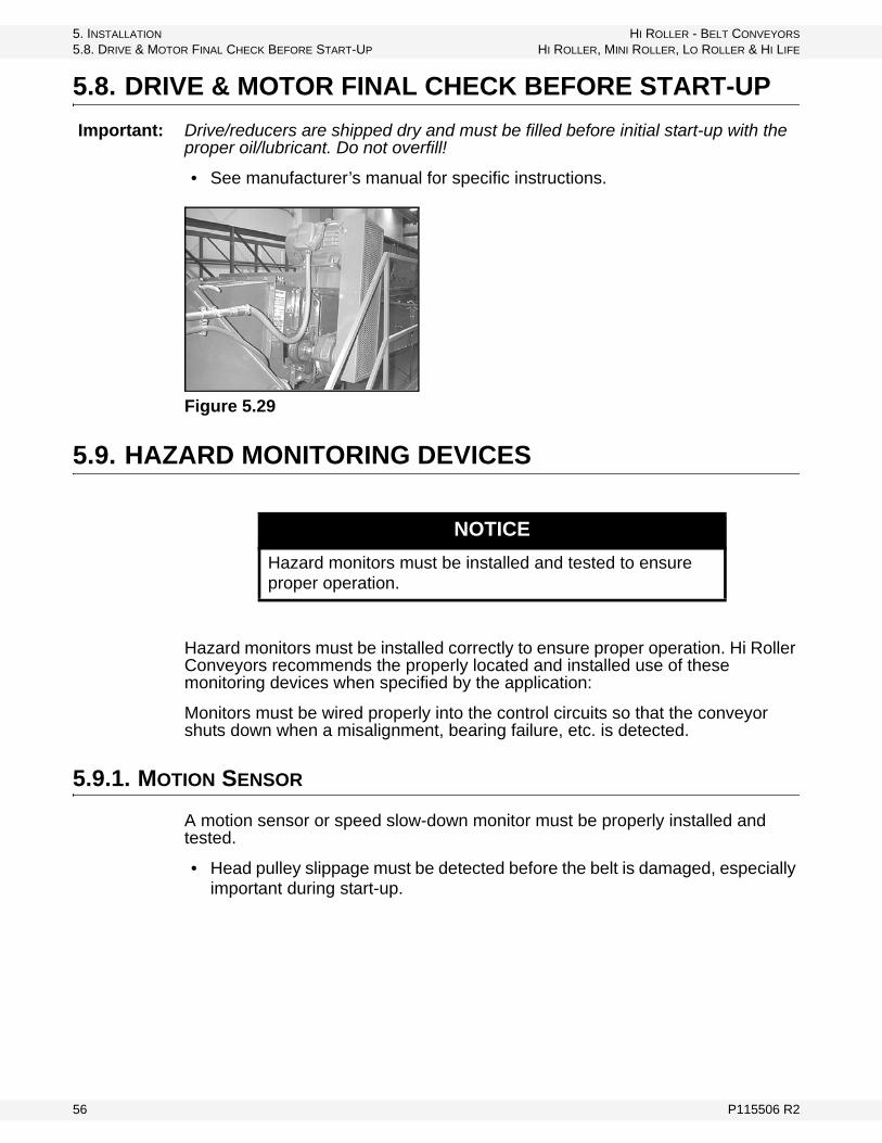
5.8. DRIVE & MOTOR FINAL CHECK BEFORE START-UP
Important: Drive/reducers are shipped dry and must be filled before initial start-up with the proper oil/lubricant. Do not overfill!
• See manufacturer’s manual for specific instructions.
Figure 5.29
5.9. HAZARD MONITORING DEVICES
Hazard monitors must be installed correctly to ensure proper operation. Hi Roller Conveyors recommends the properly located and installed use of these monitoring devices when specified by the application:
Monitors must be wired properly into the control circuits so that the conveyor shuts down when a misalignment, bearing failure, etc. is detected.
5.9.1. MOTION SENSOR
A motion sensor or speed slow-down monitor must be properly installed and tested.
• Head pulley slippage must be detected before the belt is damaged, especially important during start-up.
NOTICE
Hazard monitors must be installed and tested to ensure proper operation.
56 P115506 R2

HI ROLLER - BELT CONVEYORS 5. INSTALLATION
HI ROLLER, MINI ROLLER, LO ROLLER & HI LIFE 5.9. HAZARD MONITORING DEVICES
Figure 5.30
Figure 5.31
P115506 R2 57

5. INSTALLATION HI ROLLER - BELT CONVEYORS
5.9. HAZARD MONITORING DEVICES HI ROLLER, MINI ROLLER, LO ROLLER & HI LIFE
5.9.2. PLUG SWITCH
Properly installed and tested plug switches must be included in the design.
Figure 5.32
Figure 5.33
58 P115506 R2

HI ROLLER - BELT CONVEYORS 5. INSTALLATION
HI ROLLER, MINI ROLLER, LO ROLLER & HI LIFE 5.9. HAZARD MONITORING DEVICES
5.9.3. BELT ALIGNMENT MONITORS
Note: The belt must be properly installed and tracked before belt alignment monitors can be installed. Refer to Section 5.4.
Note: Model number equals the width of the belt.
Conveyor belt alignment monitors must be wired properly into the control circuits so that the conveyor shuts down when a belt misalignment is detected.
STANDARD HEAD SECTION (Figure 5.34)
• The head pulley and belt alignment can be monitored with one rub block installed near the top centerline of the head pulley to detect belt and head pul-ley misalignment.
• The return belt alignment can be monitored with one rub block installed on the bottom return belt.
Figure 5.34
P115506 R2 59

5. INSTALLATION HI ROLLER - BELT CONVEYORS
5.9. HAZARD MONITORING DEVICES HI ROLLER, MINI ROLLER, LO ROLLER & HI LIFE
SNUBBER HEAD SECTION (Figure 5.35)
• The head pulley and belt alignment can be monitored with one rub block installed near the top centerline of the head pulley to detect a belt and head pulley misalignment.
• The snubber pulley and return belt alignment can be monitored with one rub block installed near the top centerline of the snubber pulley and will detect a return belt misalignment and snubber pulley misalignment.
Figure 5.35
60 P115506 R2
HI ROLLER - BELT CONVEYORS 5. INSTALLATION
HI ROLLER, MINI ROLLER, LO ROLLER & HI LIFE 5.9. HAZARD MONITORING DEVICES
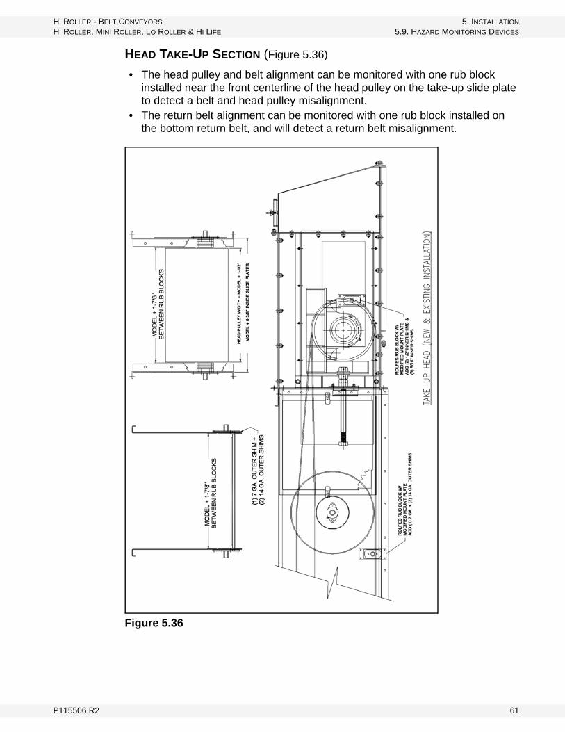
HEAD TAKE-UP SECTION (Figure 5.36)
• The head pulley and belt alignment can be monitored with one rub block installed near the front centerline of the head pulley on the take-up slide plate to detect a belt and head pulley misalignment.
• The return belt alignment can be monitored with one rub block installed on the bottom return belt, and will detect a return belt misalignment.
Figure 5.36
P115506 R2 61

5. INSTALLATION HI ROLLER - BELT CONVEYORS
5.9. HAZARD MONITORING DEVICES HI ROLLER, MINI ROLLER, LO ROLLER & HI LIFE
REVERSIBLE DRIVE END SECTION (Figure 5.37)
• The drive pulley alignment can be monitored with one surface mounted sen-sor block installed near the front centerline of the drive pulley to detect a drive pulley misalignment.
• The return belt alignment can be monitored with one rub block installed on the bottom return belt, and will detect a return belt misalignment.
Figure 5.37
62 P115506 R2

HI ROLLER - BELT CONVEYORS 5. INSTALLATION
HI ROLLER, MINI ROLLER, LO ROLLER & HI LIFE 5.9. HAZARD MONITORING DEVICES
REVERSIBLE NON-DRIVE END SECTION—NEW (Figure 5.38)
• The non-drive pulley alignment can be monitored with one surface mounted sensor block installed near the front centerline of the non-drive pulley to detect a non-drive pulley misalignment.
• The return belt alignment can be monitored with one rub block installed on the bottom return belt in the special section for mounting the sensor, and will detect a return belt misalignment.
Figure 5.38
P115506 R2 63
5. INSTALLATION HI ROLLER - BELT CONVEYORS
5.9. HAZARD MONITORING DEVICES HI ROLLER, MINI ROLLER, LO ROLLER & HI LIFE
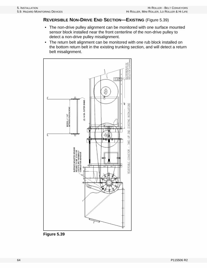
REVERSIBLE NON-DRIVE END SECTION—EXISTING (Figure 5.39)
• The non-drive pulley alignment can be monitored with one surface mounted sensor block installed near the front centerline of the non-drive pulley to detect a non-drive pulley misalignment.
• The return belt alignment can be monitored with one rub block installed on the bottom return belt in the existing trunking section, and will detect a return belt misalignment.
Figure 5.39
64 P115506 R2
HI ROLLER - BELT CONVEYORS 5. INSTALLATION
HI ROLLER, MINI ROLLER, LO ROLLER & HI LIFE 5.9. HAZARD MONITORING DEVICES
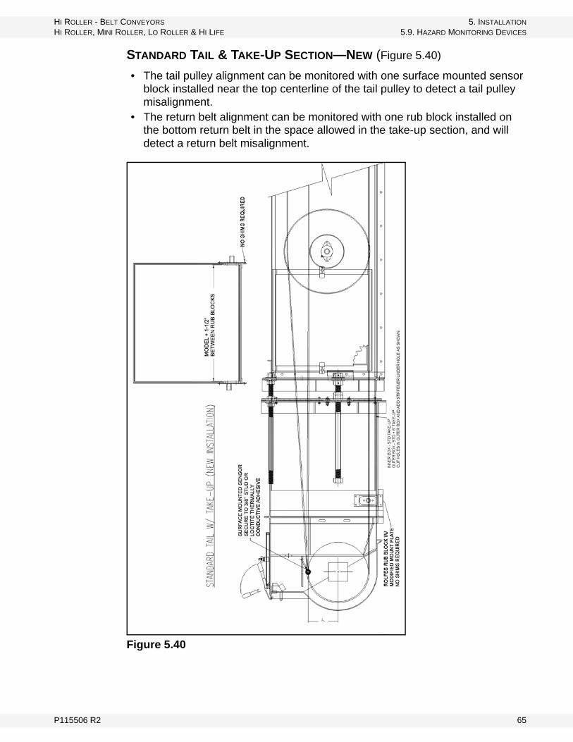
STANDARD TAIL & TAKE-UP SECTION—NEW (Figure 5.40)
• The tail pulley alignment can be monitored with one surface mounted sensor block installed near the top centerline of the tail pulley to detect a tail pulley misalignment.
• The return belt alignment can be monitored with one rub block installed on the bottom return belt in the space allowed in the take-up section, and will detect a return belt misalignment.
Figure 5.40
P115506 R2 65

5. INSTALLATION HI ROLLER - BELT CONVEYORS
5.9. HAZARD MONITORING DEVICES HI ROLLER, MINI ROLLER, LO ROLLER & HI LIFE
STANDARD TAIL & TAKE-UP SECTION—EXISTING (Figure 5.41)
• The tail pulley alignment can be monitored with one surface mounted sensor block installed near the top centerline of the tail pulley to detect a tail pulley misalignment.
• The return belt alignment can be monitored with one rub block installed on the bottom return belt in the existing trunking section, and will detect a return belt misalignment.
Figure 5.41
66 P115506 R2
HI ROLLER - BELT CONVEYORS 5. INSTALLATION
HI ROLLER, MINI ROLLER, LO ROLLER & HI LIFE 5.9. HAZARD MONITORING DEVICES
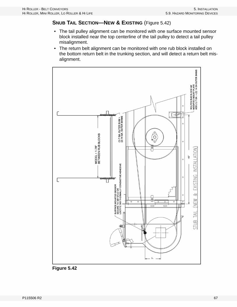
SNUB TAIL SECTION—NEW & EXISTING (Figure 5.42)
• The tail pulley alignment can be monitored with one surface mounted sensor block installed near the top centerline of the tail pulley to detect a tail pulley misalignment.
• The return belt alignment can be monitored with one rub block installed on the bottom return belt in the trunking section, and will detect a return belt mis-alignment.
Figure 5.42
P115506 R2 67
5. INSTALLATION HI ROLLER - BELT CONVEYORS
5.9. HAZARD MONITORING DEVICES HI ROLLER, MINI ROLLER, LO ROLLER & HI LIFE
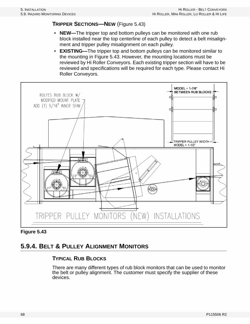
TRIPPER SECTIONS—NEW (Figure 5.43)
• NEW—The tripper top and bottom pulleys can be monitored with one rub block installed near the top centerline of each pulley to detect a belt misalign-ment and tripper pulley misalignment on each pulley.
• EXISTING—The tripper top and bottom pulleys can be monitored similar to the mounting in Figure 5.43. However, the mounting locations must be reviewed by Hi Roller Conveyors. Each existing tripper section will have to be reviewed and specifications will be required for each type. Please contact Hi Roller Conveyors.
Figure 5.43
5.9.4. BELT & PULLEY ALIGNMENT MONITORS
TYPICAL RUB BLOCKS
There are many different types of rub block monitors that can be used to monitor the belt or pulley alignment. The customer must specify the supplier of these devices.
68 P115506 R2

HI ROLLER - BELT CONVEYORS 5. INSTALLATION
HI ROLLER, MINI ROLLER, LO ROLLER & HI LIFE 5.9. HAZARD MONITORING DEVICES
Figure 5.44
Figure 5.45 and 5.46 show the mounting of a rub block in the sidewall of a Hi Roller Conveyor. Please note that these illustrations use inner or outer shims, required to properly set the width between the rub blocks.
All applications require different shim arrangements to properly locate the rub blocks. The number of shims will vary depending on the mounting and appli-cation. Please contact Hi Roller Conveyors to confirm the proper location and mounting of these devices.
Figure 5.45 Brass Rub Block Mounting w/ Inner Shims
BRASS WITH MOUNTING BOLTS
BRASS WITH WIRING HARNESS AND MOUNTING BOLTS WIRING HARNESS
W/ TEMPERATURE SENSOR MOLDED IN THREADED BRASS BOLT HEAD
P115506 R2 69

5. INSTALLATION HI ROLLER - BELT CONVEYORS
5.9. HAZARD MONITORING DEVICES HI ROLLER, MINI ROLLER, LO ROLLER & HI LIFE
Figure 5.46 Brass Rub Block Mounting w/ Outer Shims
STANDARD HEAD SECTIONS & SNUBBER HEAD SECTIONS
Figure 5.47
70 P115506 R2
HI ROLLER - BELT CONVEYORS 5. INSTALLATION
HI ROLLER, MINI ROLLER, LO ROLLER & HI LIFE 5.9. HAZARD MONITORING DEVICES
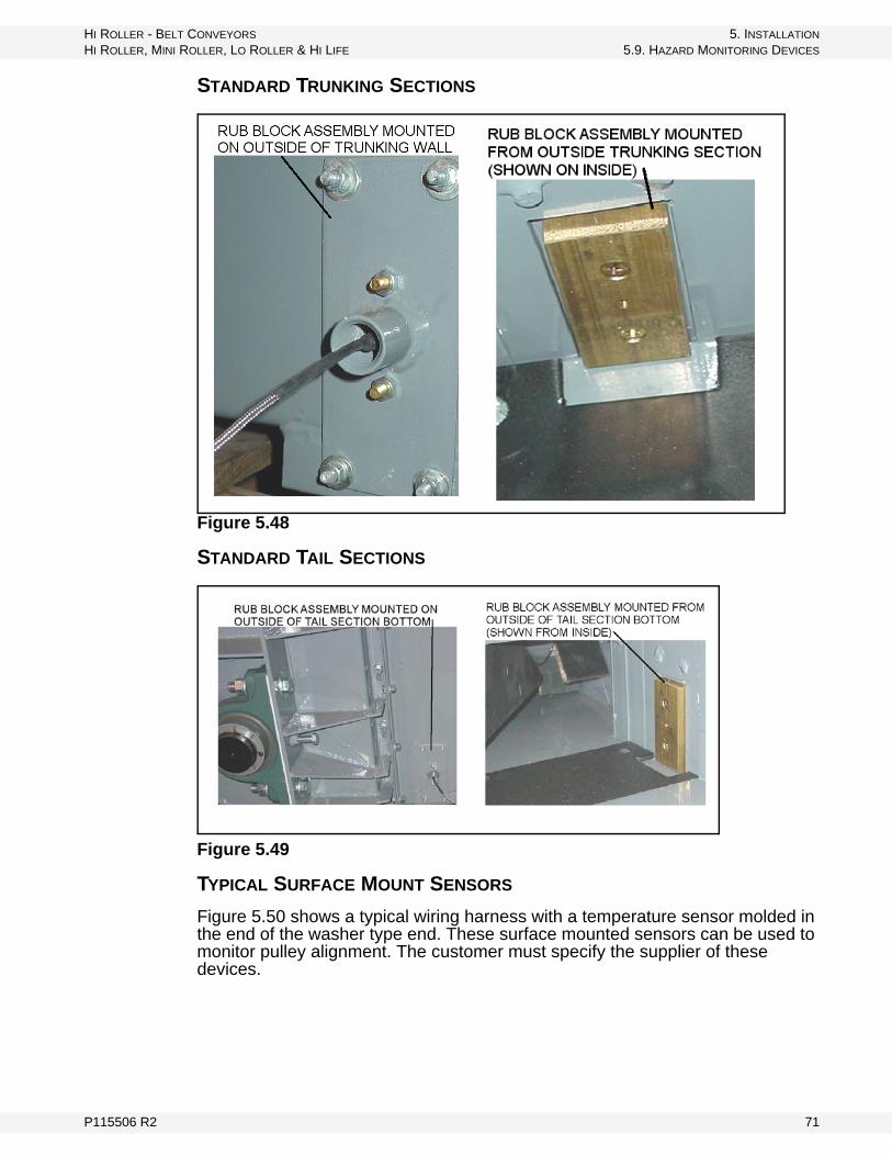
STANDARD TRUNKING SECTIONS
Figure 5.48
STANDARD TAIL SECTIONS
Figure 5.49
TYPICAL SURFACE MOUNT SENSORS
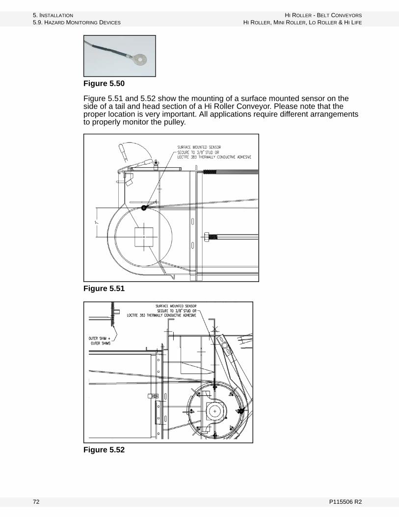
Figure 5.50 shows a typical wiring harness with a temperature sensor molded in the end of the washer type end. These surface mounted sensors can be used to monitor pulley alignment. The customer must specify the supplier of these devices.
P115506 R2 71
5. INSTALLATION HI ROLLER - BELT CONVEYORS
5.9. HAZARD MONITORING DEVICES HI ROLLER, MINI ROLLER, LO ROLLER & HI LIFE
Figure 5.50
Figure 5.51 and 5.52 show the mounting of a surface mounted sensor on the side of a tail and head section of a Hi Roller Conveyor. Please note that the proper location is very important. All applications require different arrangements to properly monitor the pulley.
Figure 5.51
Figure 5.52
72 P115506 R2
HI ROLLER - BELT CONVEYORS 5. INSTALLATION
HI ROLLER, MINI ROLLER, LO ROLLER & HI LIFE 5.9. HAZARD MONITORING DEVICES
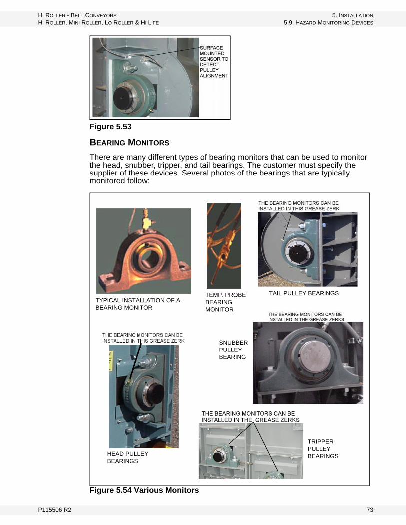
Figure 5.53
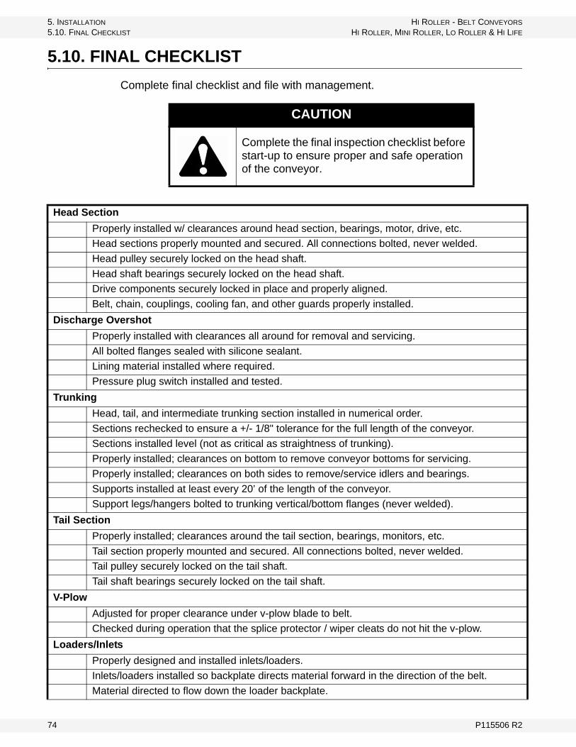
BEARING MONITORS
There are many different types of bearing monitors that can be used to monitor the head, snubber, tripper, and tail bearings. The customer must specify the supplier of these devices. Several photos of the bearings that are typically monitored follow:
Figure 5.54 Various Monitors
TYPICAL INSTALLATION OF A BEARING MONITOR
TEMP. PROBE BEARING MONITOR
TAIL PULLEY BEARINGS
HEAD PULLEY BEARINGS
SNUBBER PULLEY BEARING
TRIPPER PULLEY BEARINGS
P115506 R2 73
5. INSTALLATION HI ROLLER - BELT CONVEYORS
5.10. FINAL CHECKLIST HI ROLLER, MINI ROLLER, LO ROLLER & HI LIFE
5.10. FINAL CHECKLIST
Complete final checklist and file with management.
CAUTION
Complete the final inspection checklist before start-up to ensure proper and safe operation of the conveyor.
Head Section
Properly installed w/ clearances around head section, bearings, motor, drive, etc.
Head sections properly mounted and secured. All connections bolted, never welded.
Head pulley securely locked on the head shaft.
Head shaft bearings securely locked on the head shaft.
Drive components securely locked in place and properly aligned.
Belt, chain, couplings, cooling fan, and other guards properly installed.
Discharge Overshot
Properly installed with clearances all around for removal and servicing.
All bolted flanges sealed with silicone sealant.
Lining material installed where required.
Pressure plug switch installed and tested.
Trunking
Head, tail, and intermediate trunking section installed in numerical order.
Sections rechecked to ensure a +/- 1/8" tolerance for the full length of the conveyor.
Sections installed level (not as critical as straightness of trunking).
Properly installed; clearances on bottom to remove conveyor bottoms for servicing.
Properly installed; clearances on both sides to remove/service idlers and bearings.
Supports installed at least every 20’ of the length of the conveyor.
Support legs/hangers bolted to trunking vertical/bottom flanges (never welded).
Tail Section
Properly installed; clearances around the tail section, bearings, monitors, etc.
Tail section properly mounted and secured. All connections bolted, never welded.
Tail pulley securely locked on the tail shaft.
Tail shaft bearings securely locked on the tail shaft.
V-Plow
Adjusted for proper clearance under v-plow blade to belt.
Checked during operation that the splice protector / wiper cleats do not hit the v-plow.
Loaders/Inlets
Properly designed and installed inlets/loaders.
Inlets/loaders installed so backplate directs material forward in the direction of the belt.
Material directed to flow down the loader backplate.
74 P115506 R2
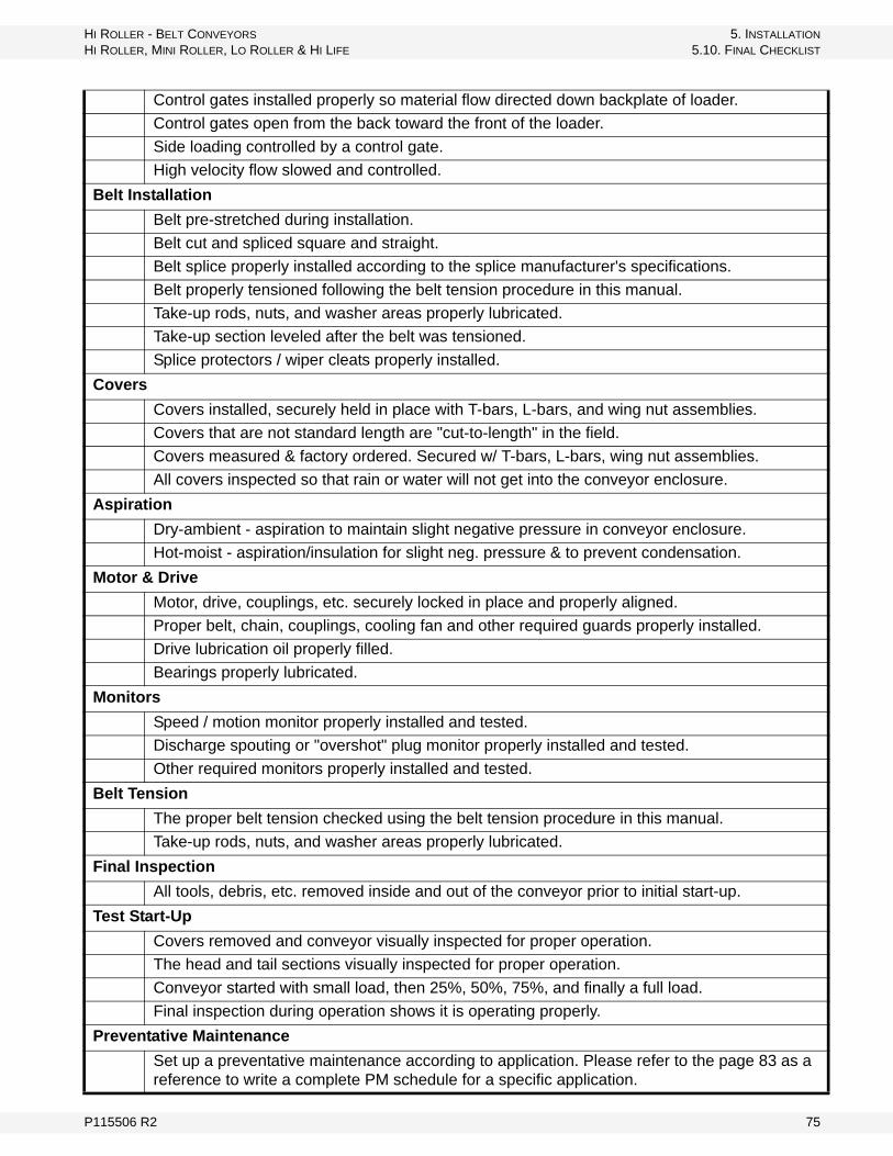
HI ROLLER - BELT CONVEYORS 5. INSTALLATION
HI ROLLER, MINI ROLLER, LO ROLLER & HI LIFE 5.10. FINAL CHECKLIST
Control gates installed properly so material flow directed down backplate of loader.
Control gates open from the back toward the front of the loader.
Side loading controlled by a control gate.
High velocity flow slowed and controlled.
Belt Installation
Belt pre-stretched during installation.
Belt cut and spliced square and straight.
Belt splice properly installed according to the splice manufacturer's specifications.
Belt properly tensioned following the belt tension procedure in this manual.
Take-up rods, nuts, and washer areas properly lubricated.
Take-up section leveled after the belt was tensioned.
Splice protectors / wiper cleats properly installed.
Covers
Covers installed, securely held in place with T-bars, L-bars, and wing nut assemblies.
Covers that are not standard length are "cut-to-length" in the field.
Covers measured & factory ordered. Secured w/ T-bars, L-bars, wing nut assemblies.
All covers inspected so that rain or water will not get into the conveyor enclosure.
Aspiration
Dry-ambient - aspiration to maintain slight negative pressure in conveyor enclosure.
Hot-moist - aspiration/insulation for slight neg. pressure & to prevent condensation.
Motor & Drive
Motor, drive, couplings, etc. securely locked in place and properly aligned.
Proper belt, chain, couplings, cooling fan and other required guards properly installed.
Drive lubrication oil properly filled.
Bearings properly lubricated.
Monitors
Speed / motion monitor properly installed and tested.
Discharge spouting or "overshot" plug monitor properly installed and tested.
Other required monitors properly installed and tested.
Belt Tension
The proper belt tension checked using the belt tension procedure in this manual.
Take-up rods, nuts, and washer areas properly lubricated.
Final Inspection
All tools, debris, etc. removed inside and out of the conveyor prior to initial start-up.
Test Start-Up
Covers removed and conveyor visually inspected for proper operation.
The head and tail sections visually inspected for proper operation.
Conveyor started with small load, then 25%, 50%, 75%, and finally a full load.
Final inspection during operation shows it is operating properly.
Preventative Maintenance
Set up a preventative maintenance according to application. Please refer to the page 83 as a reference to write a complete PM schedule for a specific application.
P115506 R2 75

5. INSTALLATION HI ROLLER - BELT CONVEYORS
5.11. TEST START-UP HI ROLLER, MINI ROLLER, LO ROLLER & HI LIFE
5.11. TEST START-UP
1. Remove covers for visual checks.2. Have personnel ready to shut down immediately.3. Visually check head section.4. Visually check tail section and v-plow.5. Visually check intermediate trunking sections.6. Test operate while personnel visually check all sections.7. Start-up with small material load, checking visually.8. Operate with 25% load, checking visually.9. Operate with 50% load, checking visually.10. Operate with 75% load, checking visually.11. Operate with full load, checking visually.
5.12. FINAL INSPECTION DURING OPERATION
1. Remove covers for visual checks with personnel ready to shut down immediately if there is a problem.
2. The conveyor should be inspected from the head section to the tail section to be sure everything is operating properly.
3. Make sure to inspect belt tracking, loading, discharging, clearances, self-cleaning, reloading, etc.
4. Visually check head section.5. Visually check tail section and v-plow.6. Visually check intermediate trunking sections.7. Operate while personnel visually check all sections.
Important: Regular inspections and preventative maintenance are very important to the proper operation of a Hi Roller Conveyor.
76 P115506 R2

HI ROLLER - BELT CONVEYORS 5. INSTALLATION
HI ROLLER, MINI ROLLER, LO ROLLER & HI LIFE 5.12. FINAL INSPECTION DURING OPERATION
Please fill out the information below and send a copy by mail or fax to Hi Roller Conveyors.
Conveyor Owner/Company ___________________________________
Contact __________________________________________________
Address __________________________________________________
City _____________________________________________________
Zip/Postal Code ____________________________________________
PHONE: _________________________FAX: ___________________
P115506 R2 77

5. INSTALLATION HI ROLLER - BELT CONVEYORS
5.12. FINAL INSPECTION DURING OPERATION HI ROLLER, MINI ROLLER, LO ROLLER & HI LIFE
78 P115506 R2

HI ROLLER - BELT CONVEYORS 6. OPERATION
HI ROLLER, MINI ROLLER, LO ROLLER & HI LIFE 6.1. PRE-OPERATIONAL CHECKLIST
6. Operation
6.1. PRE-OPERATIONAL CHECKLIST
Before operating conveyor the first time and then at monthly intervals, the operator must confirm the following:
• Fasteners are secure.• Drive belt(s) are not frayed or damaged.• Drive belt(s) are properly adjusted and aligned.• Conveyor belt is properly adjusted and aligned.• Access covers are in place and secure.• Guards are in place and secure.• Proper maintenance has been performed.• Know how to safely shut down conveyor in an emergency.
6.2. CONVEYOR DRIVE & LOCKOUT PROCEDURE
6.3. OPERATING PROCEDURE
6.3.1. START-UP AND BREAK-IN
1. Complete the checklist at the beginning of this section.2. Start electric motor, then feed small material load into conveyor, checking
visually.3. For initial startup, remove covers for visual checks.4. Have personnel ready to shut down immediately in case there is a problem.
Important: When starting conveyor for the first time, be prepared for an emergency shutdown in case of excessive vibration or noise.
WARNING Before continuing, ensure you have read and understand the relevant information in the safety section. Safety information is provided to help prevent serious injury, death, or property damage.
Drive Type Before Operation Lockout
Electric Motor Before starting motor, ensure
• motor is properly grounded• pulley guards are in place and
secure
The electric motor should be equipped with a main power disconnect switch capable of being locked in the off-position only. The switch should be in the locked position during shutdown or whenever maintenance is performed on the conveyor.
If reset is required, disconnect all power before resetting motor.
P115506 R1 79
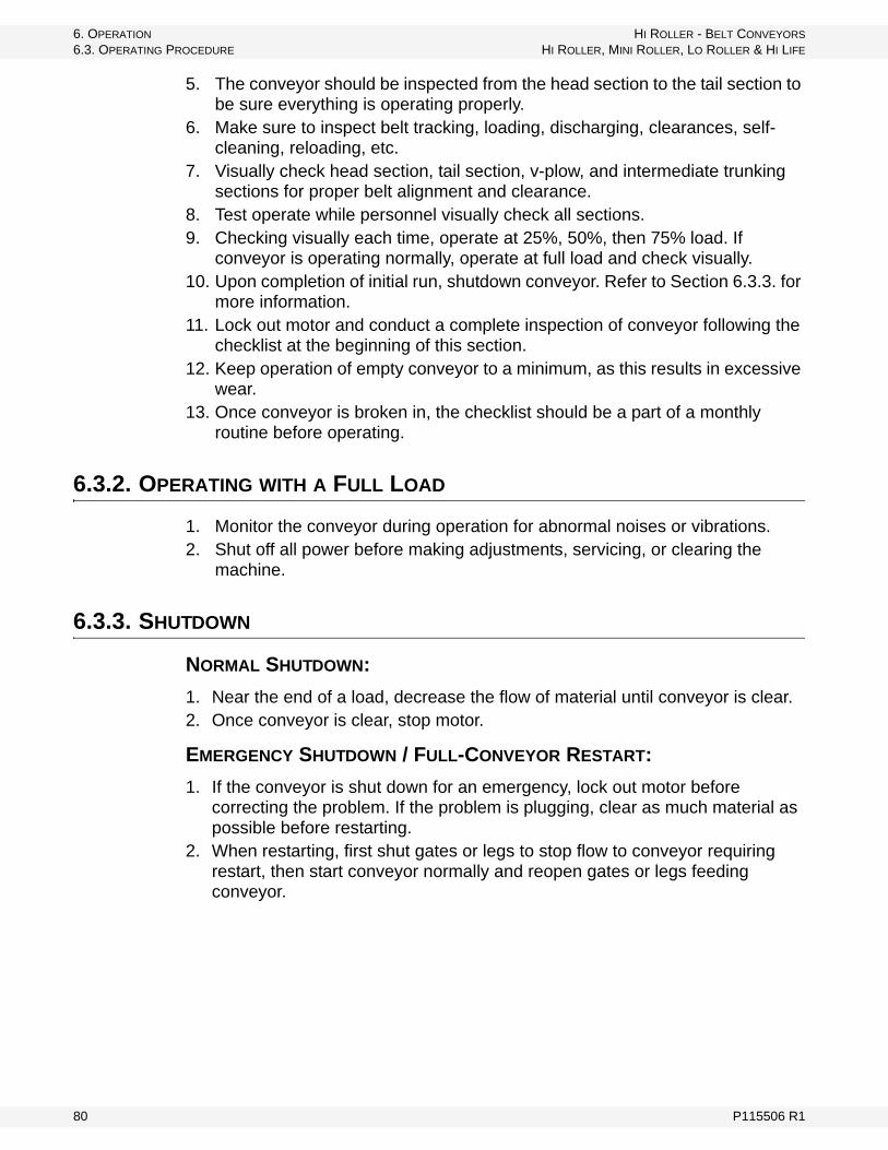
6. OPERATION HI ROLLER - BELT CONVEYORS
6.3. OPERATING PROCEDURE HI ROLLER, MINI ROLLER, LO ROLLER & HI LIFE
5. The conveyor should be inspected from the head section to the tail section to be sure everything is operating properly.
6. Make sure to inspect belt tracking, loading, discharging, clearances, self-cleaning, reloading, etc.
7. Visually check head section, tail section, v-plow, and intermediate trunking sections for proper belt alignment and clearance.
8. Test operate while personnel visually check all sections.9. Checking visually each time, operate at 25%, 50%, then 75% load. If
conveyor is operating normally, operate at full load and check visually.10. Upon completion of initial run, shutdown conveyor. Refer to Section 6.3.3. for
more information.11. Lock out motor and conduct a complete inspection of conveyor following the
checklist at the beginning of this section.12. Keep operation of empty conveyor to a minimum, as this results in excessive
wear.13. Once conveyor is broken in, the checklist should be a part of a monthly
routine before operating.
6.3.2. OPERATING WITH A FULL LOAD
1. Monitor the conveyor during operation for abnormal noises or vibrations.2. Shut off all power before making adjustments, servicing, or clearing the
machine.
6.3.3. SHUTDOWN
NORMAL SHUTDOWN:
1. Near the end of a load, decrease the flow of material until conveyor is clear.2. Once conveyor is clear, stop motor.
EMERGENCY SHUTDOWN / FULL-CONVEYOR RESTART:
1. If the conveyor is shut down for an emergency, lock out motor before correcting the problem. If the problem is plugging, clear as much material as possible before restarting.
2. When restarting, first shut gates or legs to stop flow to conveyor requiring restart, then start conveyor normally and reopen gates or legs feeding conveyor.
80 P115506 R1
HI ROLLER - BELT CONVEYORS 6. OPERATION
HI ROLLER, MINI ROLLER, LO ROLLER & HI LIFE 6.3. OPERATING PROCEDURE
6.3.4. OPERATING TIPS
• Always listen for any unusual sounds or noises. If any are heard, stop the machine and determine the source. Correct the problem before resuming work.
• Do not run the conveyor for long periods of time without material on the belt-ing. It increases belt wear.
• Do not flood feed.
6.3.5. PLUGGING
1. If the conveyor becomes plugged, stop conveyor motor and lockout/tagout motor.
2. Shut inlet feed gates or stop other equipment feeding inlet to stop flow to plugged conveyor and determine the source of the plug.
3. Check tail section first by removing cover or opening inspection doors and clean out.
4. Check head/discharge and clean out.5. Check the return belt top and bottom for plugging and clean out.6. When restarting, start normally, then reopen gates or legs feeding conveyor.
P115506 R1 81

6. OPERATION HI ROLLER - BELT CONVEYORS
6.3. OPERATING PROCEDURE HI ROLLER, MINI ROLLER, LO ROLLER & HI LIFE
82 P115506 R1
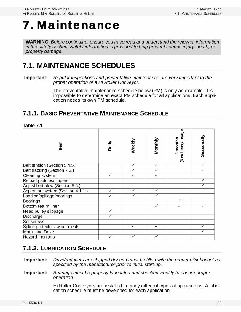
HI ROLLER - BELT CONVEYORS 7. MAINTENANCE
HI ROLLER, MINI ROLLER, LO ROLLER & HI LIFE 7.1. MAINTENANCE SCHEDULES
7. Maintenance
7.1. MAINTENANCE SCHEDULES
Important: Regular inspections and preventative maintenance are very important to the proper operation of a Hi Roller Conveyor.
The preventative maintenance schedule below (PM) is only an example. It is impossible to determine an exact PM schedule for all applications. Each appli-cation needs its own PM schedule.
7.1.1. BASIC PREVENTATIVE MAINTENANCE SCHEDULE
7.1.2. LUBRICATION SCHEDULE
Important: Drive/reducers are shipped dry and must be filled with the proper oil/lubricant as specified by the manufacturer prior to initial start-up.
Important: Bearings must be properly lubricated and checked weekly to ensure proper operation.
Hi Roller Conveyors are installed in many different types of applications. A lubri-cation schedule must be developed for each application.
WARNING Before continuing, ensure you have read and understand the relevant information in the safety section. Safety information is provided to help prevent serious injury, death, or property damage.
Table 7.1
Item
Dai
ly
Wee
kly
Mo
nth
ly
6 m
on
ths
(3 w
/ h
eav
y u
sag
e
Sea
son
ally
Belt tension (Section 5.4.5.) Belt tracking (Section 7.2.) Cleaning system Reload paddles/flippers Adjust belt plow (Section 5.6.) Aspiration system (Section 4.1.1.) Loading/spillage/bearings Bearings Bottom return liner Head pulley slippage Discharge Set screwsSplice protector / wiper cleats Motor and Drive Hazard monitors
P115506 R1 83

7. MAINTENANCE HI ROLLER - BELT CONVEYORS
7.2. BELT TRACKING GUIDE HI ROLLER, MINI ROLLER, LO ROLLER & HI LIFE
• Drive/gear reducers—see the manufacturer's recommendations for each application. Extra instructions have been included in this manual if a drive/gear reducer is supplied with the conveyor.
• Head, snubber, and tail shaft bearings—see the manufacturer's recom-mendations for each application (included in the supplied with the con-veyor).
• The idler bearing lubrication schedule will vary by model, size, and belt speed. See Table 7.2 for idler shaft speeds.
Contact Hi Roller’s engineering department with any further questions.
Important: Over-greasing of any bearing will cause premature failure. It is important that greasing follow the lubrication schedule.
7.2. BELT TRACKING GUIDE
BASIC RULES:
Important: Conveyor belt tension and tracking alignment must be checked weekly; more often with seasonal weather changes.
• The basic and primary rule of tracking a conveyor belt is simple: the belt moves toward the end of the roll it contacts first.
• The conveyor structure must be straight (relative to centerline) and level (side to side).
• All pulleys, snub rollers, carrying idlers, and return idlers must be square with the frame (perpendicular to belt centerline) and parallel to each other. Check by measuring diagonals - they should be equal.
• Belt tension must be great enough to prevent slippage between the drive pul-ley and the belt.
• Force the belt to conform to the crown on the crowned pulleys if they are used.
Note: Belt should not be over-tensioned. Consult your belt manufacturer.
• Cleanliness is essential to good belt tracking. Foreign matter creates a new roll or pulley face, adversely affecting tracking.
Table 7.2 Idler Shaft Speeds - Hi Roller Conveyors - All Models
Model Size Idler Dia.rpm@350
Belt Speed
rpm@700Belt
Speed
Mini Roller All 4” 334 668
Lo Roller All 4” 334 668
Hi Bulk All 4” 334 668
Hi Roller 18” & 22” - Std. Idler 8-1/4” 162 324
Hi Roller 18” & 22” - HD Idler 8-1/2” 157 315
Hi Roller 26” & up - Std. Idler 8-1/4” 162 324
Hi Roller 26” & up - HD Idler 8-5/8” 155 310
Hi Life All 5-5/8” 238 475
84 P115506 R1
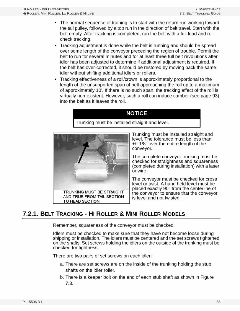
HI ROLLER - BELT CONVEYORS 7. MAINTENANCE
HI ROLLER, MINI ROLLER, LO ROLLER & HI LIFE 7.2. BELT TRACKING GUIDE
• The normal sequence of training is to start with the return run working toward the tail pulley, followed by a top run in the direction of belt travel. Start with the belt empty. After tracking is completed, run the belt with a full load and re-check tracking.
• Tracking adjustment is done while the belt is running and should be spread over some length of the conveyor preceding the region of trouble. Permit the belt to run for several minutes and for at least three full belt revolutions after idler has been adjusted to determine if additional adjustment is required. If the belt has over-corrected, it should be restored by moving back the same idler without shifting additional idlers or rollers.
• Tracking effectiveness of a roll/crown is approximately proportional to the length of the unsupported span of belt approaching the roll up to a maximum of approximately 10'. If there is no such span, the tracking effect of the roll is virtually non-existent. However, such a roll can induce camber (see page 93) into the belt as it leaves the roll.
Trunking must be installed straight and level. The tolerance must be less than +/- 1/8" over the entire length of the conveyor.
The complete conveyor trunking must be checked for straightness and squareness (completed during installation) with a laser or wire.
The conveyor must be checked for cross level or twist. A hand held level must be placed exactly 90° from the centerline of the conveyor to ensure that the conveyor is level and not twisted.
7.2.1. BELT TRACKING - HI ROLLER & MINI ROLLER MODELS
Remember, squareness of the conveyor must be checked.
Idlers must be checked to make sure that they have not become loose during shipping or installation. The idlers must be centered and the set screws tightened on the shafts. Set screws holding the idlers on the outside of the trunking must be checked for tightness.
There are two pairs of set screws on each idler:
a. There are set screws are on the inside of the trunking holding the stub shafts on the idler roller.
b. There is a keeper bolt on the end of each stub shaft as shown in Figure 7.3.
NOTICE
Trunking must be installed straight and level.
P115506 R1 85
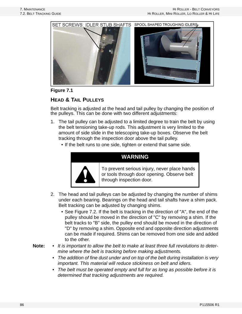
7. MAINTENANCE HI ROLLER - BELT CONVEYORS
7.2. BELT TRACKING GUIDE HI ROLLER, MINI ROLLER, LO ROLLER & HI LIFE
Figure 7.1
HEAD & TAIL PULLEYS
Belt tracking is adjusted at the head and tail pulley by changing the position of the pulleys. This can be done with two different adjustments:
1. The tail pulley can be adjusted to a limited degree to train the belt by using the belt tensioning take-up rods. This adjustment is very limited to the amount of side slide in the telescoping take-up boxes. Observe the belt tracking through the inspection door above the tail pulley.
• If the belt runs to one side, tighten or extend that same side.
2. The head and tail pulleys can be adjusted by changing the number of shims under each bearing. Bearings on the head and tail shafts have a shim pack. Belt tracking can be adjusted by changing shims.
• See Figure 7.2. If the belt is tracking in the direction of "A", the end of the pulley should be moved in the direction of "C" by removing a shim. If the belt tracks to "B" side, the pulley end should be moved in the direction of "D" by removing a shim. Opposite end and opposite direction adjustments can be made if required. Shims can be removed from one side and added to the other.
Note: • It is important to allow the belt to make at least three full revolutions to deter-mine where the belt is tracking before making adjustments.
• The addition of fine dust under and on top of the belt during installation is very important. This material will reduce stickiness on belt and idlers.
• The belt must be operated empty and full for as long as possible before it is determined that tracking adjustments are required.
WARNING
To prevent serious injury, never place hands or tools through door opening. Observe belt through inspection door.
86 P115506 R1
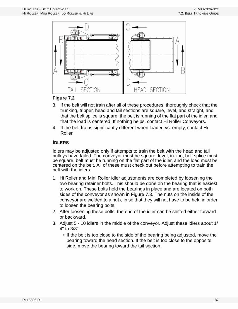
HI ROLLER - BELT CONVEYORS 7. MAINTENANCE
HI ROLLER, MINI ROLLER, LO ROLLER & HI LIFE 7.2. BELT TRACKING GUIDE
Figure 7.2
3. If the belt will not train after all of these procedures, thoroughly check that the trunking, tripper, head and tail sections are square, level, and straight, and that the belt splice is square, the belt is running of the flat part of the idler, and that the load is centered. If nothing helps, contact Hi Roller Conveyors.
4. If the belt trains significantly different when loaded vs. empty, contact Hi Roller.
IDLERS
Idlers may be adjusted only if attempts to train the belt with the head and tail pulleys have failed. The conveyor must be square, level, in-line, belt splice must be square, belt must be running on the flat part of the idler, and the load must be centered on the belt. All of these must check out before attempting to train the belt with the idlers.
1. Hi Roller and Mini Roller idler adjustments are completed by loosening the two bearing retainer bolts. This should be done on the bearing that is easiest to work on. These bolts hold the bearings in place and are located on both sides of the conveyor as shown in Figure 7.3. The nuts on the inside of the conveyor are welded to a nut clip so that they will not have to be held in order to loosen the bearing bolts.
2. After loosening these bolts, the end of the idler can be shifted either forward or backward.
3. Adjust 5 - 10 idlers in the middle of the conveyor. Adjust these idlers about 1/4" to 3/8".
• If the belt is too close to the side of the bearing being adjusted, move the bearing toward the head section. If the belt is too close to the opposite side, move the bearing toward the tail section.
P115506 R1 87

7. MAINTENANCE HI ROLLER - BELT CONVEYORS
7.2. BELT TRACKING GUIDE HI ROLLER, MINI ROLLER, LO ROLLER & HI LIFE
Figure 7.3
4. If the belt is tracking to the right in the conveyor, the end of the idler should be shifted in "A" position. If the belt is tracking to the left, shift the end of the idler in the "B" position. See Figure 7.4. Remember, the belt will move toward the end of the idler that the belt first contacts.
Note: "Right" or "Left" is determined by standing at the tail section and looking toward the head section of the conveyor.
Figure 7.4
5. Test-run the conveyor both empty and properly loaded. Continue the training process until the desired training is achieved.
6. If adjusting the bearings on one side of the conveyor does not achieve proper training, repeat the procedure on the opposite side of the conveyor.
88 P115506 R1

HI ROLLER - BELT CONVEYORS 7. MAINTENANCE
HI ROLLER, MINI ROLLER, LO ROLLER & HI LIFE 7.2. BELT TRACKING GUIDE
7.2.2. BELT TRACKING - HI LIFE MODELS
Remember, squareness of the conveyor must be checked.
Idlers must be checked to be sure that they have not become loose during shipping or installation. The flat-horizontal idlers must be centered and the set screws tightened on the shafts. Set screws holding the side-troughing 45° idlers on the outside of the trunking must be checked for tightness. Do not turn the keeper bolt in the center of the shaft.
There are two pairs of set screws:
a. Flat-horizontal idler: These set screws are on the inside of the trunking holding the stub shafts on the idler roller. There is a keeper bolt on the end of each stub shaft as shown in Figure 7.6.
b. Side-troughing 45° idlers: These set screws are on the outside of the trunking holding the stationary shaft of each idler. There is a keeper bolt on the end of the stationary shaft as shown Figure 7.5.
Figure 7.5
HEAD & TAIL PULLEYS
Belt tracking is adjusted at the head and tail pulley by changing the position of the pulleys. See “Head & Tail Pulleys” on page 86.
IDLERS
Idlers may be adjusted only if attempts to train the belt with the head and tail pulleys have failed. The conveyor must be square, level, in-line, belt splice must be square, belt must be running on the flat part of the idler, and the load must be centered on the belt. All of these must check out before attempting the train the belt with the idlers.
1. To adjust Hi Life idlers, adjust the flat horizontal idler. Loosen the two bearing retainer bolts on the bearing that is easiest to work on. These bolts hold the bearings in place and are located on both sides of the conveyor as shown in Figure 7.6.
°
P115506 R1 89
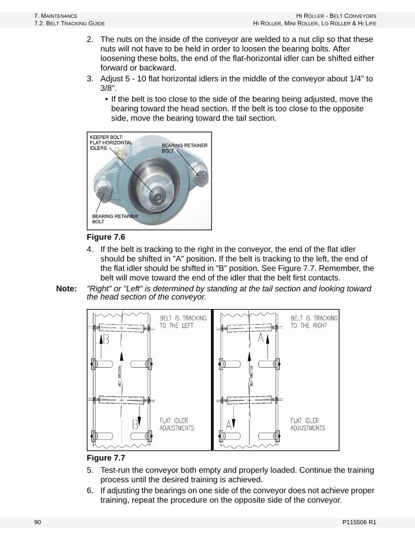
7. MAINTENANCE HI ROLLER - BELT CONVEYORS
7.2. BELT TRACKING GUIDE HI ROLLER, MINI ROLLER, LO ROLLER & HI LIFE
2. The nuts on the inside of the conveyor are welded to a nut clip so that these nuts will not have to be held in order to loosen the bearing bolts. After loosening these bolts, the end of the flat-horizontal idler can be shifted either forward or backward.
3. Adjust 5 - 10 flat horizontal idlers in the middle of the conveyor about 1/4" to 3/8".
• If the belt is too close to the side of the bearing being adjusted, move the bearing toward the head section. If the belt is too close to the opposite side, move the bearing toward the tail section.
Figure 7.6
4. If the belt is tracking to the right in the conveyor, the end of the flat idler should be shifted in "A" position. If the belt is tracking to the left, the end of the flat idler should be shifted in "B" position. See Figure 7.7. Remember, the belt will move toward the end of the idler that the belt first contacts.
Note: "Right" or "Left" is determined by standing at the tail section and looking toward the head section of the conveyor.
Figure 7.7
5. Test-run the conveyor both empty and properly loaded. Continue the training process until the desired training is achieved.
6. If adjusting the bearings on one side of the conveyor does not achieve proper training, repeat the procedure on the opposite side of the conveyor.
90 P115506 R1

HI ROLLER - BELT CONVEYORS 7. MAINTENANCE
HI ROLLER, MINI ROLLER, LO ROLLER & HI LIFE 7.2. BELT TRACKING GUIDE
7.2.3. BELT TRACKING - LO ROLLER & HI BULK MODELS
Remember, squareness of the conveyor must be checked.
Idlers must be checked to be sure that they have not become loose during shipping or installation. The idlers must be centered and the set screws tightened on the shafts. Bearing retainer bolts holding the idlers on the outside of the trunking must be checked for tightness. There is a pair of set screws on each idler bearing. These set screws are on the bearing collar as shown in Figure 7.8.
Figure 7.8
HEAD & TAIL PULLEYS
Belt tracking is adjusted at the head and tail pulley by changing the position of the pulleys. See “Head & Tail Pulleys” on page 86.
IDLERS
Idlers may be adjusted only if attempts to train the belt with the head and tail pulleys have failed. The conveyor must be square, level, in-line, belt splice must be square, belt must be running on the flat part of the idler, and the load must be centered on the belt. All of these must check out before attempting the train the belt with the idlers.
1. Lo Roller and Hi Bulk idler adjustments are completed by loosening the two bearing retainer bolts. (See Figure 7.8.) The idler bearing on the side that is easiest to work on should be adjusted first. The nuts are welded to a nut retainer plate. (See Figure 7.9.)
2. After loosening these bolts, the end of the idler can be shifted. Adjust 5-10 idlers in the middle of the conveyor about 1/4" - 3/8".
• If the belt is too close to the side of the bearing being adjusted, move the bearing toward the head section. If the belt is too close to the opposite side, move the bearing toward the tail section.
P115506 R1 91

7. MAINTENANCE HI ROLLER - BELT CONVEYORS
7.2. BELT TRACKING GUIDE HI ROLLER, MINI ROLLER, LO ROLLER & HI LIFE
Figure 7.9
3. If the belt is tracking to the right in the conveyor, the end of the idler should be shifted in "A" position. If the belt is tracking to the left, the end of the idler should be shifted in "B" position. (See Figure 7.10.) Remember, the belt will move toward the end of the idler that the belt first contacts.
Note: "Right" or "Left" is determined by standing at the tail section and looking toward the head section of the conveyor.
Figure 7.10
4. Test-run the conveyor both empty and properly loaded. Continue the training process until the desired training is achieved.
5. If adjusting the bearings on one side of the conveyor that does not achieve proper training, repeat the procedure on the opposite side.
92 P115506 R1

HI ROLLER - BELT CONVEYORS 7. MAINTENANCE
HI ROLLER, MINI ROLLER, LO ROLLER & HI LIFE 7.2. BELT TRACKING GUIDE
7.2.4. BELT TRACKING MISALIGNMENTS
BELT TRACKING - LOADED
1. The belt is being loaded off-center. This must be corrected by ensuring that material flows evenly down the back slope of all inlets, and that inlet skirts are installed properly and are free from wear. See Section 4.6. and 5.3.1.
2. An internal bend called a belt camber (see page 93) could exist in the belt. This is a belt defect and must be checked with a special procedure. Contact Hi Roller Conveyors.
3. The belt has not been properly tensioned. See Section 5.4.5.4. The belt has not yet stabilized. The belt and conveyor must be allowed to
break-in or run-in over a period of one to two days of operation without a load.
5. The belt runs off-center at or near the splice, and then returns to the center after the splice has passed - most likely caused by an improper splice instal-lation where the splice is not square. The belt will have to be spliced square by following the procedure. See Section 5.4.
6. The belt runs out of alignment in an area away from the splice and then returns to the center. Inspect the area where the belt runs out of alignment for cuts, burns, or other localized damage. The defective section of belt must be replaced.
BELT TRACKING - EMPTY
1. The belt may not be contacting the center flat area of the idlers. This can be caused by a stiff belt. This must be corrected; review belt specifications with Hi Roller engineering department.
2. The above points 2 - 6 also apply to an empty belt.
7.2.5. BELT CAMBER
If unbalanced warp tensions exist in a conveyor belt, that belt will usually assume a "crescent" or "banana" shape when laid flat on a horizontal surface. This deviation from a straight line is called "camber."
To measure belt camber:
1. Unroll on a flat surface. 2. Grasp one end of the belt and drag in a perfectly straight line for 10’ to 20’. If
the belt is too heavy for one person to move, clamp the end to a fork lift and drag.
3. At this point, the belt should lie flat. Unequal and unresolved warp tensions in the belt will cause it to assume a "crescent" or "banana" shape.
• It is extremely important that the preceding procedure be followed to the letter. It is very difficult to have both edges of the belt at the same thick-ness--particularly wide belts. Accordingly, if we simply unroll the belt on a flat surface, that belt will always unroll in a banana shape due to geome-try, not unbalanced warp tensions. Dragging one end of the belt for 10’ to
P115506 R1 93

7. MAINTENANCE HI ROLLER - BELT CONVEYORS
7.3. IDLER REPLACEMENT - HI ROLLER MODELS HI ROLLER, MINI ROLLER, LO ROLLER & HI LIFE
20’ eliminates this geometrical consideration and tells us whether we have a cambered belt.
4. Camber is measured by drawing a taut line along one edge of the belt (inward camber edge) and measuring maximum deviation from that taut line to the belt at the center point of that line.
5. Compute percent camber:• % camber = [max. deviation (inches/cm)] / [length of taut line (inches)] x
100
Camber can be instilled into a belt during the slitting operation if one of the slitting knives is dull. A dull slitting knife will tear the fill yarns (crosswise yarns) rather than cut them. While the belt is in roll form, the side of the belt which has gone through the dull knife will exhibit a "fuzzy" appearance due to the torn fill yarn. Usually, this type of camber will be less than 1/2 of 1% and can be easily pulled out when the belt is properly tensioned and tracked.
Camber is typically instilled into a belt during improper storage.
Currently, there is no accepted camber standard in the US market. For a maximum acceptable camber relative to a given conveyor belt construction, please contact your belt manufacturer.
7.2.6. SKEW (BOW)
The horizontal fill yarns in the belt carcass will usually lie perpendicular to the belt centerline. Any deviation from the perpendicular by the fill yarn is called "skew" or "bow."
A skewed pick in a plain or square weave is cause for concern since it is generally indicative of unbalanced warp tensions and will usually go hand-in-hand with a significant camber.
In a straight warp or solid woven carcass, skew is of little significance. It is usually a cosmetic defect and is not indicative of a cambered belt.
7.3. IDLER REPLACEMENT - HI ROLLER MODELS
Figure 7.11 Hi Roller Idler and Typical Trunking
94 P115506 R1
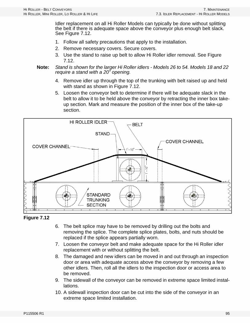
HI ROLLER - BELT CONVEYORS 7. MAINTENANCE
HI ROLLER, MINI ROLLER, LO ROLLER & HI LIFE 7.3. IDLER REPLACEMENT - HI ROLLER MODELS
Idler replacement on all Hi Roller Models can typically be done without splitting the belt if there is adequate space above the conveyor plus enough belt slack. See Figure 7.12.
1. Follow all safety precautions that apply to the installation.2. Remove necessary covers. Secure covers.3. Use the stand to raise up belt to allow Hi Roller idler removal. See Figure
7.12.Note: Stand is shown for the larger Hi Roller idlers - Models 26 to 54. Models 18 and 22
require a stand with a 20” opening.
4. Remove idler up through the top of the trunking with belt raised up and held with stand as shown in Figure 7.12.
5. Loosen the conveyor belt to determine if there will be adequate slack in the belt to allow it to be held above the conveyor by retracting the inner box take-up section. Mark and measure the position of the inner box of the take-up section.
Figure 7.12
6. The belt splice may have to be removed by drilling out the bolts and removing the splice. The complete splice plates, bolts, and nuts should be replaced if the splice appears partially worn.
7. Loosen the conveyor belt and make adequate space for the Hi Roller idler replacement with or without splitting the belt.
8. The damaged and new idlers can be moved in and out through an inspection door or area with adequate access above the conveyor by removing a few other idlers. Then, roll all the idlers to the inspection door or access area to be removed.
9. The sidewall of the conveyor can be removed in extreme space limited instal-lations.
10. A sidewall inspection door can be cut into the side of the conveyor in an extreme space limited installation.
P115506 R1 95

7. MAINTENANCE HI ROLLER - BELT CONVEYORS
7.3. IDLER REPLACEMENT - HI ROLLER MODELS HI ROLLER, MINI ROLLER, LO ROLLER & HI LIFE
11. In some cases, the inlet/loader skirts, crossbraces, and other components may have to be removed for proper clearance to replace the Hi Roller idler.
Figure 7.13
Note: The crossbrace and come-a-longs in Figure 7.13 are for Models 25-54 of the larger Hi Roller idlers. Models 18 and 22 require a height opening of 1’8”.
12. Loosen jam nut on set bolts on each side of the idler. See Figure 7.14.
Figure 7.14
13. Mark the location of the idler bearings on the sidewall of the trunking so that the new idler bearings can be installed in the same location.
14. Loosen and remove bolts holding idler bearings in place.a. Nut retainers on the inside of the trunking hold the nuts and therefore a
wrench is not required on the inside nut. See Figure 7.15.
96 P115506 R1

HI ROLLER - BELT CONVEYORS 7. MAINTENANCE
HI ROLLER, MINI ROLLER, LO ROLLER & HI LIFE 7.3. IDLER REPLACEMENT - HI ROLLER MODELS
b. The nut retainers can be held in place by using a self-drilling and -tapping screw from the outside of the trunking sidewall just above the centerline of the bearing bolts.
Figure 7.15
15. Remove the idler bearing and stub shaft assembly as a total unit. See Figure 7.16.a. A slide-hammer or another type of pulling device may be required to help
pull this assembly. (Use by removing the keeper bolt and large washer in the end of the stub shaft and then inserting the slide-hammer in the end threads of the stub shaft.)
b. A long rod may have to be used to drive out the idler bearing and stub shaft assembly from the opposite side if there is not adequate clearance to use a slide-hammer or another type of pulling device.
16. Remove the idler through the top of the conveyor, inspection door, or another access space.
Figure 7.16
17. Place the new idler in the trunking in the same manner.18. Install the new bearing and stub shaft assembly.
P115506 R1 97
7. MAINTENANCE HI ROLLER - BELT CONVEYORS
7.3. IDLER REPLACEMENT - HI ROLLER MODELS HI ROLLER, MINI ROLLER, LO ROLLER & HI LIFE
• The bearings and stub shafts should be replaced as an assembly when-ever replacing the idler.
• If the existing bearings and stub shafts are to be reinstalled, make sure that the stub shafts have the burrs and cuts removed with emory cloth.
• The inside of the idler center tube should be coated with an anti-seize type product. This will allow for easier replacement in the future.
19. Align the bearings with the marks previously made during disassembly.20. Tighten the bearing bolts on both sides - this MUST be done first.21. Remove the self-drilling and -tapping screws installed to hold the nut
retainers. 22. Align the idler in the center of the trunking.23. Tighten the set bolts securely.24. Spin the idler to make sure it is centered and secure.25. Retighten the set bolts.26. Tighten the jam nuts on the set bolts.27. Spin the idler to make sure it is centered and secure28. Lubricate the bearings if they have not been filled with grease.
• It is very important to not over-grease these small bearings. It only requires a small amount of grease to fill this type of bearing.
• Check the bearing manual for the proper grease for a specific application.29. Inspect and remove all tools, parts, and components from inside and out of
the conveyor.30. Complete a final inspection of the idlers and the conveyor in general.31. Tension the belt properly using the “Belt Tension Procedure” on page 48. Set
the tension according to the specifications for this specific conveyor.32. Install the covers making sure they are secured properly.33. Test operate the conveyor without a load to make sure that the idlers are
operating properly.34. Test operate the conveyor with a load to make sure that the idlers are
operating properly.
98 P115506 R1

HI ROLLER - BELT CONVEYORS 7. MAINTENANCE
HI ROLLER, MINI ROLLER, LO ROLLER & HI LIFE 7.4. IDLER REPLACEMENT - HI LIFE MODELS
7.4. IDLER REPLACEMENT - HI LIFE MODELS
Figure 7.17 Typical Hi Life Cross Section
Idler replacement on all Hi Life Models can typically be done without splitting the belt.
7.4.1. BOTTOM FLAT IDLER
1. Follow all safety precautions that apply to the installation.2. Remove necessary covers. Secure covers during the replacement process.3. Loosen jam nut on set bolts on each side of the idler. See Figure 7.18.
Figure 7.18
4. Mark the location of the idler bearings on the sidewall of the trunking so that the new idler bearings can be installed in the same location.
5. Loosen and remove bolts holding idler bearings in place.
P115506 R1 99
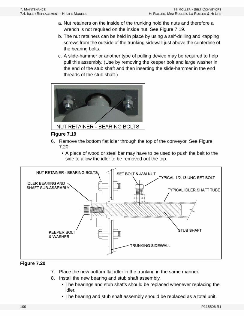
7. MAINTENANCE HI ROLLER - BELT CONVEYORS
7.4. IDLER REPLACEMENT - HI LIFE MODELS HI ROLLER, MINI ROLLER, LO ROLLER & HI LIFE
a. Nut retainers on the inside of the trunking hold the nuts and therefore a wrench is not required on the inside nut. See Figure 7.19.
b. The nut retainers can be held in place by using a self-drilling and -tapping screws from the outside of the trunking sidewall just above the centerline of the bearing bolts.
c. A slide-hammer or another type of pulling device may be required to help pull this assembly. (Use by removing the keeper bolt and large washer in the end of the stub shaft and then inserting the slide-hammer in the end threads of the stub shaft.)
Figure 7.19
6. Remove the bottom flat idler through the top of the conveyor. See Figure 7.20.
• A piece of wood or steel bar may have to be used to push the belt to the side to allow the idler to be removed out the top.
Figure 7.20
7. Place the new bottom flat idler in the trunking in the same manner.8. Install the new bearing and stub shaft assembly.
• The bearings and stub shafts should be replaced whenever replacing the idler.
• The bearing and stub shaft assembly should be replaced as a total unit.
100 P115506 R1
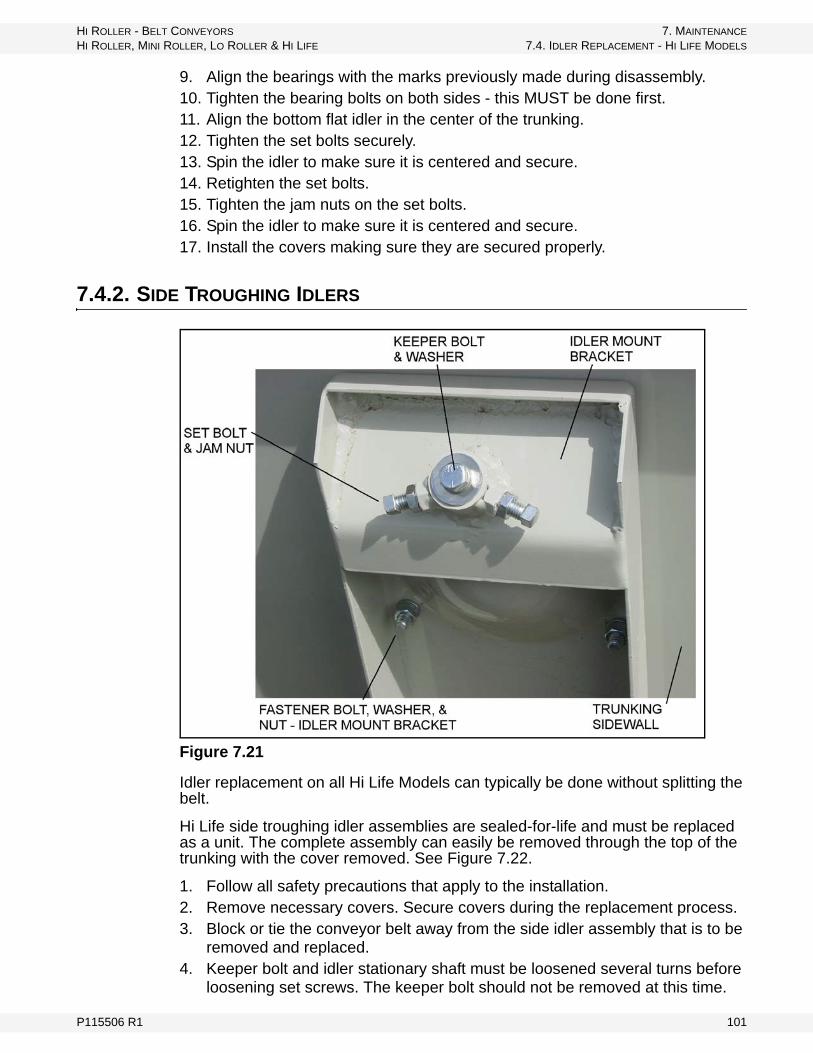
HI ROLLER - BELT CONVEYORS 7. MAINTENANCE
HI ROLLER, MINI ROLLER, LO ROLLER & HI LIFE 7.4. IDLER REPLACEMENT - HI LIFE MODELS
9. Align the bearings with the marks previously made during disassembly.10. Tighten the bearing bolts on both sides - this MUST be done first.11. Align the bottom flat idler in the center of the trunking.12. Tighten the set bolts securely.13. Spin the idler to make sure it is centered and secure.14. Retighten the set bolts.15. Tighten the jam nuts on the set bolts.16. Spin the idler to make sure it is centered and secure.17. Install the covers making sure they are secured properly.
7.4.2. SIDE TROUGHING IDLERS
Figure 7.21
Idler replacement on all Hi Life Models can typically be done without splitting the belt.
Hi Life side troughing idler assemblies are sealed-for-life and must be replaced as a unit. The complete assembly can easily be removed through the top of the trunking with the cover removed. See Figure 7.22.
1. Follow all safety precautions that apply to the installation.2. Remove necessary covers. Secure covers during the replacement process.3. Block or tie the conveyor belt away from the side idler assembly that is to be
removed and replaced.4. Keeper bolt and idler stationary shaft must be loosened several turns before
loosening set screws. The keeper bolt should not be removed at this time.
P115506 R1 101

7. MAINTENANCE HI ROLLER - BELT CONVEYORS
7.4. IDLER REPLACEMENT - HI LIFE MODELS HI ROLLER, MINI ROLLER, LO ROLLER & HI LIFE
5. Set bolts and idler stationary shaft must first be loosened. Loosen the locknuts and then turn out the set bolts until the idler stationary shaft is free.
6. The keeper bolt can now be removed completely so the side idler assembly can be pushed in through the mount collar.
7. The side troughing idler assembly must be pushed in completely through the dust seals into the conveyor trunking.
8. The side troughing idler assembly can be rotated and removed straight through the open top of the conveyor trunking.
Figure 7.22
9. The complete assembly can easily be installed through the top of the conveyor trunking with the cover removed. The steps are just the reverse of the procedure above to remove the complete idler assembly.
102 P115506 R1
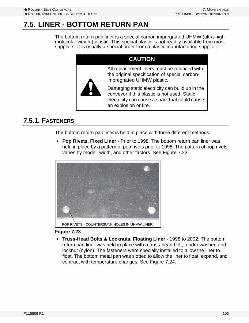
HI ROLLER - BELT CONVEYORS 7. MAINTENANCE
HI ROLLER, MINI ROLLER, LO ROLLER & HI LIFE 7.5. LINER - BOTTOM RETURN PAN
7.5. LINER - BOTTOM RETURN PAN
The bottom return pan liner is a special carbon impregnated UHMW (ultra-high molecular weight) plastic. This special plastic is not readily available from most suppliers. It is usually a special order from a plastic manufacturing supplier.
7.5.1. FASTENERS
The bottom return pan liner is held in place with three different methods:
• Pop Rivets, Fixed Liner - Prior to 1998: The bottom return pan liner was held in place by a pattern of pop rivets prior to 1998. The pattern of pop rivets varies by model, width, and other factors. See Figure 7.23.
Figure 7.23
• Truss-Head Bolts & Locknuts, Floating Liner - 1998 to 2002: The bottom return pan liner was held in place with a truss-head bolt, fender washer, and locknut (nylon). The fasteners were specially installed to allow the liner to float. The bottom metal pan was slotted to allow the liner to float, expand, and contract with temperature changes. See Figure 7.24.
CAUTION
All replacement liners must be replaced with the original specification of special carbon-impregnated UHMW plastic.
Damaging static electricity can build up in the conveyor if this plastic is not used. Static electricity can cause a spark that could cause an explosion or fire.
P115506 R1 103

7. MAINTENANCE HI ROLLER - BELT CONVEYORS
7.5. LINER - BOTTOM RETURN PAN HI ROLLER, MINI ROLLER, LO ROLLER & HI LIFE
Figure 7.24
• Pop Rivets, Floating Liner - after 2002: The bottom return pan liner has been held in place since 2002 with special pop rivets. The pop rivets are spe-cially installed to allow the liner to float. The bottom metal pan is slotted to allow the liner to float, expand, and contract with temperature changes. The pop rivets are installed with special equipment at the factory. See Figure 7.25.
Figure 7.25
7.5.2. REPLACEMENT
To replace and reinstall the bottom return pan:
• Pop Rivets, Fixed Liner - prior to 1998: First, remove all old pop rivets. The new UHMW liner must be installed with new pop rivets in newly drilled holes in the metal bottom.
• Truss Head Bolts & Locknuts, Floating Liner - 1998 to 2002: First remove all old bolts, washers, and nuts. It is recommended that they be replaced with new fasteners. See the description and illustrations on the following pages.
• Pop Rivets, Floating Liner - after 2002: The pop rivets holding the liner must be removed. The new liner must be installed with truss head bolts and lock-nuts. See Figure 7.26. Liner replacement can be done with the pan installed or removed. See Figure 7.27.
104 P115506 R1

HI ROLLER - BELT CONVEYORS 7. MAINTENANCE
HI ROLLER, MINI ROLLER, LO ROLLER & HI LIFE 7.5. LINER - BOTTOM RETURN PAN
• This liner is not tightly fastened to the bottom which allows the UHMW liner to expand and contract at a different rate than the steel bottom. The UHMW has a much greater expansion and contraction rate than steel. The steel bottom has slotted holes that will allow the liner to move. There-fore, the UHMW liner must not be tightly fastened to the bottom (Figure 7.28). The bottom return pan has slotted holes that allow the liner to move. See Figure 7.28.
• Liner replacement requires that all of the bolts, washers, and nuts first be removed and discarded.
• Remove the worn out liner.• Clean and treat any bare metal areas as required.• Install the new liner in its proper place so that the holes line up with the
holes and slotted holes in the bottom return pan.• Install all new bolts, washers, and locknuts. The locknuts should be tight-
ened and then backed off so that the bolt spins freely. • The locknuts MUST NOT be tight!• Liner joints must be level from trunking section to trunking section. This is
very important so that the return belt with splice protector / wiper cleats does not catch on these joints.
Figure 7.26
LINER PAN WITH BOLTS (TRUSS HEADS), WASHERS (FENDER), AND LOCKNUTS (NYLON)
VIEW FROM UNDER BOTTOM RETURN PAN
P115506 R1 105

7. MAINTENANCE HI ROLLER - BELT CONVEYORS
7.6. FIXED TRIPPER - ALL MODELS HI ROLLER, MINI ROLLER, LO ROLLER & HI LIFE
Figure 7.27
Figure 7.28 Liner Showing Slotted Holes
7.6. FIXED TRIPPER - ALL MODELS
Fixed trippers must be installed correctly to ensure proper operation. The following list indicates the critical areas:
1. Conveyor trunking and tripper sections must be straight and square.a. This should have been checked during installation with a laser or wire. The
conveyor must meet a +/- 1/8” tolerance. A level must be placed exactly 90° from the centerline to ensure conveyor is not twisted.
b. The tripper trunking sections must be installed in the correct order. The trunking sections leading into the tripper section are higher than the normal sections. The idler height continues to rise in each section so the belt line gradually inclines to the top tripper pulley. See Figure 7.29. The sections are numbered to make sure the sections are installed in the correct order.
LINER SHOWING SLOTTED HOLES PAN SHOWING SLOTTED HOLES
106 P115506 R1

HI ROLLER - BELT CONVEYORS 7. MAINTENANCE
HI ROLLER, MINI ROLLER, LO ROLLER & HI LIFE 7.6. FIXED TRIPPER - ALL MODELS
Figure 7.29 Typical Fixed Tripper
Figure 7.30
2. The belt must be threaded through the pulleys correctly (see Figure 7.31). To form a continuous loop, the top carrying belt isa. strung over the top of the idlers and top pulley of the tripper,
b. strung back over the top of the bottom pulley of the tripper,
c. around the bottom pulley of the tripper and back toward the head of the conveyor over the top of the idlers,
d. over the top of the head pulley and the return belt slides back on the bottom of the trunking,
e. under the belt plow just ahead of the tail pulley,
P115506 R1 107
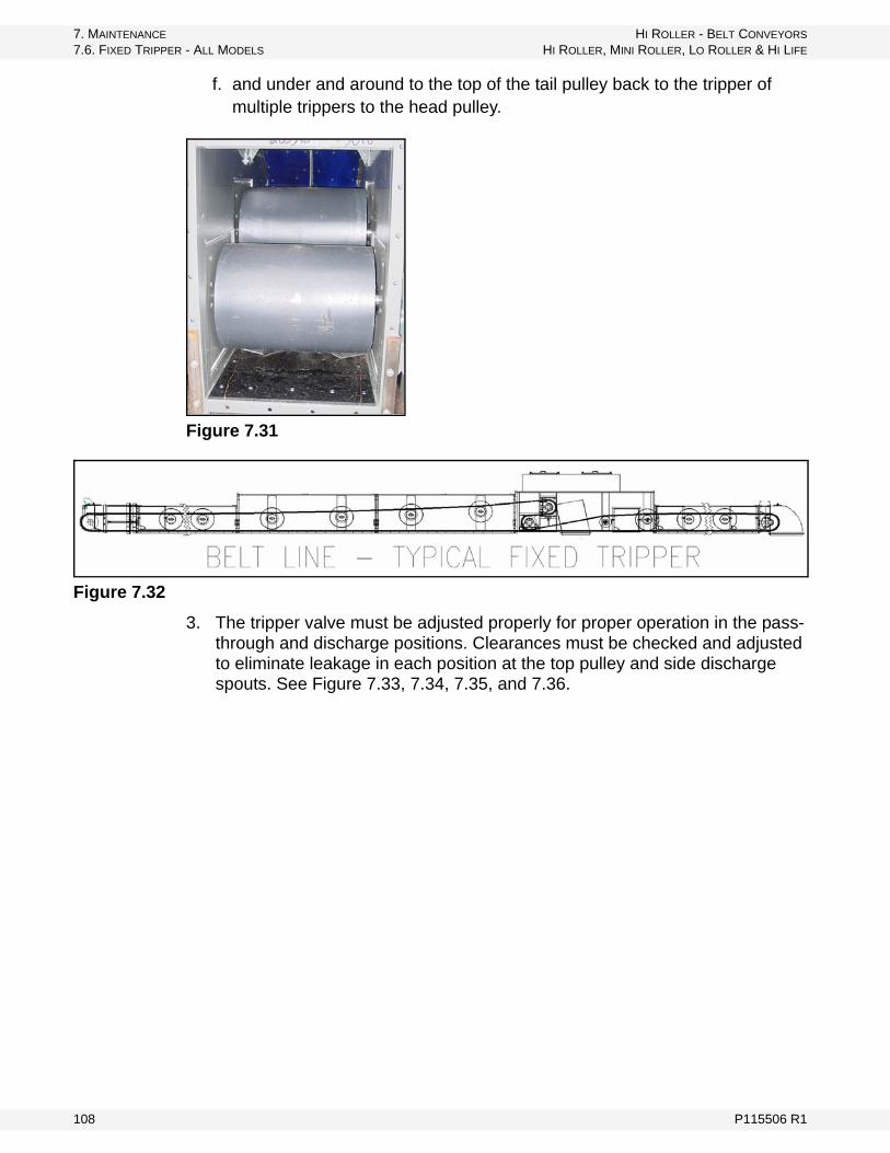
7. MAINTENANCE HI ROLLER - BELT CONVEYORS
7.6. FIXED TRIPPER - ALL MODELS HI ROLLER, MINI ROLLER, LO ROLLER & HI LIFE
f. and under and around to the top of the tail pulley back to the tripper of multiple trippers to the head pulley.
Figure 7.31
Figure 7.32
3. The tripper valve must be adjusted properly for proper operation in the pass-through and discharge positions. Clearances must be checked and adjusted to eliminate leakage in each position at the top pulley and side discharge spouts. See Figure 7.33, 7.34, 7.35, and 7.36.
108 P115506 R1

HI ROLLER - BELT CONVEYORS 7. MAINTENANCE
HI ROLLER, MINI ROLLER, LO ROLLER & HI LIFE 7.6. FIXED TRIPPER - ALL MODELS
Figure 7.33 Tripper Valve Down
Figure 7.34 Tripper Valve Up
P115506 R1 109

7. MAINTENANCE HI ROLLER - BELT CONVEYORS
7.6. FIXED TRIPPER - ALL MODELS HI ROLLER, MINI ROLLER, LO ROLLER & HI LIFE
Figure 7.35 Discharge Spout
Note: Discharge spout has removable sides for ease of relining internal wear points and a top inspection door.
110 P115506 R1

HI ROLLER - BELT CONVEYORS 7. MAINTENANCE
HI ROLLER, MINI ROLLER, LO ROLLER & HI LIFE 7.6. FIXED TRIPPER - ALL MODELS
Figure 7.36
4. Electric or manual actuators must be properly adjusted. See Figure 7.37.
P115506 R1 111

7. MAINTENANCE HI ROLLER - BELT CONVEYORS
7.6. FIXED TRIPPER - ALL MODELS HI ROLLER, MINI ROLLER, LO ROLLER & HI LIFE
Figure 7.37
5. Electric or manual stops must be properly adjusted.6. Reloading skirts must be properly installed and adjusted so that the material
is reloaded without spillage when the valve is in the pass-through position. They are shipped loose and wired to the bottom of the of the tripper section; see Figure 7.38.
Figure 7.38
7. The back-flow baffle must be properly installed and adjusted to prevent material from flowing backwards into the bottom pulley during start-up and shutdown with full loads.
NOTICE
In case of actuator malfunction, use emergency handle:• Bolt handle to pivot.• Disconnect actuator.• Rotate and lock out for pass through.
112 P115506 R1
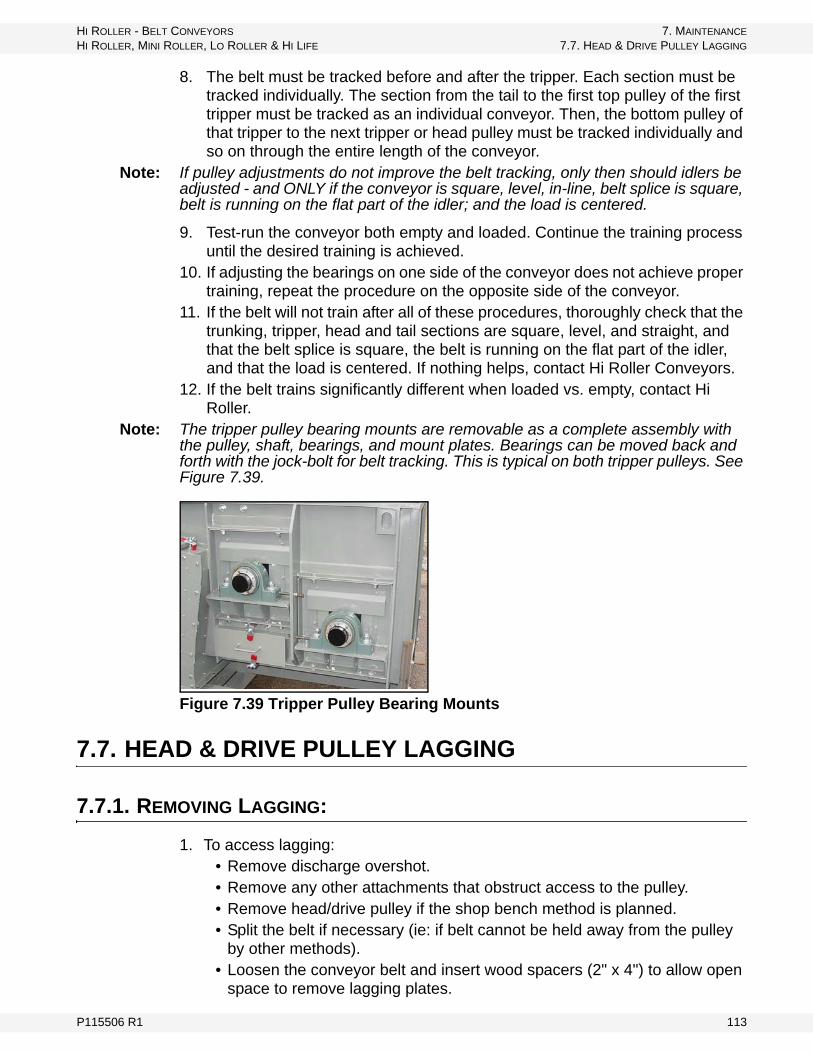
HI ROLLER - BELT CONVEYORS 7. MAINTENANCE
HI ROLLER, MINI ROLLER, LO ROLLER & HI LIFE 7.7. HEAD & DRIVE PULLEY LAGGING
8. The belt must be tracked before and after the tripper. Each section must be tracked individually. The section from the tail to the first top pulley of the first tripper must be tracked as an individual conveyor. Then, the bottom pulley of that tripper to the next tripper or head pulley must be tracked individually and so on through the entire length of the conveyor.
Note: If pulley adjustments do not improve the belt tracking, only then should idlers be adjusted - and ONLY if the conveyor is square, level, in-line, belt splice is square, belt is running on the flat part of the idler; and the load is centered.
9. Test-run the conveyor both empty and loaded. Continue the training process until the desired training is achieved.
10. If adjusting the bearings on one side of the conveyor does not achieve proper training, repeat the procedure on the opposite side of the conveyor.
11. If the belt will not train after all of these procedures, thoroughly check that the trunking, tripper, head and tail sections are square, level, and straight, and that the belt splice is square, the belt is running on the flat part of the idler, and that the load is centered. If nothing helps, contact Hi Roller Conveyors.
12. If the belt trains significantly different when loaded vs. empty, contact Hi Roller.
Note: The tripper pulley bearing mounts are removable as a complete assembly with the pulley, shaft, bearings, and mount plates. Bearings can be moved back and forth with the jock-bolt for belt tracking. This is typical on both tripper pulleys. See Figure 7.39.
Figure 7.39 Tripper Pulley Bearing Mounts
7.7. HEAD & DRIVE PULLEY LAGGING
7.7.1. REMOVING LAGGING:
1. To access lagging:• Remove discharge overshot.• Remove any other attachments that obstruct access to the pulley.• Remove head/drive pulley if the shop bench method is planned.• Split the belt if necessary (ie: if belt cannot be held away from the pulley
by other methods).• Loosen the conveyor belt and insert wood spacers (2" x 4") to allow open
space to remove lagging plates.
P115506 R1 113
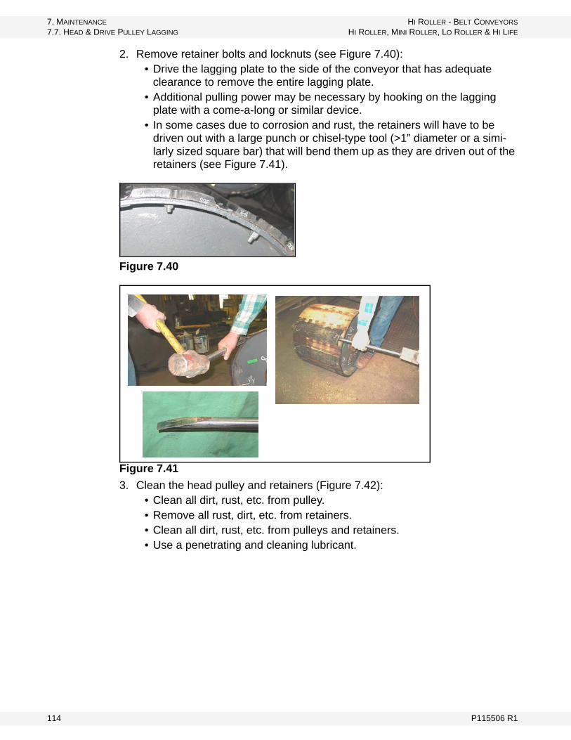
7. MAINTENANCE HI ROLLER - BELT CONVEYORS
7.7. HEAD & DRIVE PULLEY LAGGING HI ROLLER, MINI ROLLER, LO ROLLER & HI LIFE
2. Remove retainer bolts and locknuts (see Figure 7.40):• Drive the lagging plate to the side of the conveyor that has adequate
clearance to remove the entire lagging plate.• Additional pulling power may be necessary by hooking on the lagging
plate with a come-a-long or similar device.• In some cases due to corrosion and rust, the retainers will have to be
driven out with a large punch or chisel-type tool (>1” diameter or a simi-larly sized square bar) that will bend them up as they are driven out of the retainers (see Figure 7.41).
Figure 7.40
Figure 7.41
3. Clean the head pulley and retainers (Figure 7.42):• Clean all dirt, rust, etc. from pulley.• Remove all rust, dirt, etc. from retainers.• Clean all dirt, rust, etc. from pulleys and retainers.• Use a penetrating and cleaning lubricant.
114 P115506 R1
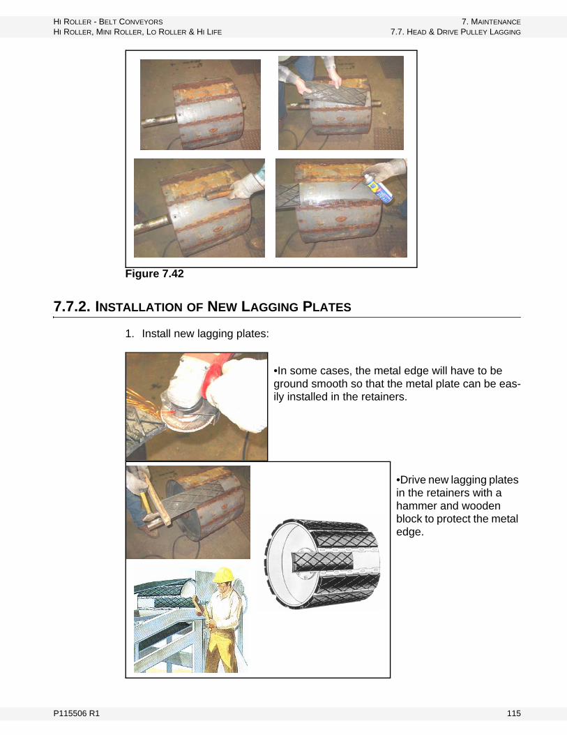
HI ROLLER - BELT CONVEYORS 7. MAINTENANCE
HI ROLLER, MINI ROLLER, LO ROLLER & HI LIFE 7.7. HEAD & DRIVE PULLEY LAGGING
Figure 7.42
7.7.2. INSTALLATION OF NEW LAGGING PLATES
1. Install new lagging plates:
•In some cases, the metal edge will have to be ground smooth so that the metal plate can be eas-ily installed in the retainers.
•Drive new lagging plates in the retainers with a hammer and wooden block to protect the metal edge.
P115506 R1 115
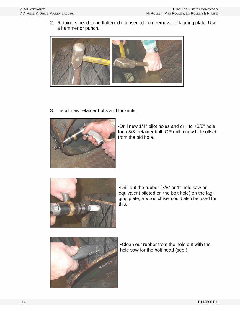
7. MAINTENANCE HI ROLLER - BELT CONVEYORS
7.7. HEAD & DRIVE PULLEY LAGGING HI ROLLER, MINI ROLLER, LO ROLLER & HI LIFE
2. Retainers need to be flattened if loosened from removal of lagging plate. Use a hammer or punch.
3. Install new retainer bolts and locknuts:
•Drill new 1/4" pilot holes and drill to +3/8" hole for a 3/8" retainer bolt, OR drill a new hole offset from the old hole.
•Drill out the rubber (7/8" or 1" hole saw or equivalent piloted on the bolt hole) on the lag-ging plate; a wood chisel could also be used for this.
•Clean out rubber from the hole cut with the hole saw for the bolt head (see ).
116 P115506 R1
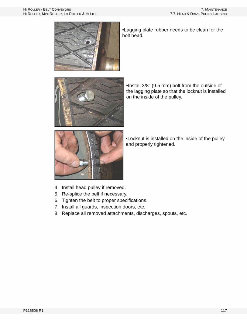
HI ROLLER - BELT CONVEYORS 7. MAINTENANCE
HI ROLLER, MINI ROLLER, LO ROLLER & HI LIFE 7.7. HEAD & DRIVE PULLEY LAGGING
•Lagging plate rubber needs to be clean for the bolt head.
•Install 3/8" (9.5 mm) bolt from the outside of the lagging plate so that the locknut is installed on the inside of the pulley.
•Locknut is installed on the inside of the pulley and properly tightened.
4. Install head pulley if removed.5. Re-splice the belt if necessary.6. Tighten the belt to proper specifications.7. Install all guards, inspection doors, etc.8. Replace all removed attachments, discharges, spouts, etc.
P115506 R1 117

7. MAINTENANCE HI ROLLER - BELT CONVEYORS
7.7. HEAD & DRIVE PULLEY LAGGING HI ROLLER, MINI ROLLER, LO ROLLER & HI LIFE
118 P115506 R1

HI ROLLER - BELT CONVEYORS 8. TROUBLESHOOTING
HI ROLLER, MINI ROLLER, LO ROLLER & HI LIFE
8. TroubleshootingTable 8.1 Belt Tracking
Problem Cause/Solution
1. All portions of the conveyor belt running to one side at a given point on the structure. Idlers immediately preceding trouble point are not at right angles to the belt direction.
• square idlers• advance, in the direction of belt travel,
the end of the idler that the belt has shifted
2. Conveyor frame or structure crooked or not square.
• stretch string along edge to determine extent of misalignment and correct
3. Sticking idlers. • clean and lubricate
4. Belt runs off terminal pulley. • check terminal pulley alignment• check alignments of idlers approaching
terminal pulley
5. Build up of material on idlers. • clean them
6. Structure not level and belt tends to shift to low side.
• level structure
7. Particular section of the conveyor belt runs to one side at all points of the conveyor.
• belt not joined square—square ends and re-splice properly
8. Bowed belt. • adjust tension or replace
9. Conveyor belt runs to one side for long distance bed.
• load being placed on belt off-center; adjust chute and loading conditions
10. Conveyor frame or structure crooked. • straighten
11. Belt is erratic - does not follow a pattern. • belt too stiff to train, use more trougha-ble belt
• increase tension to get belt to conform to the crown of the pulleys
• use more flexible belt on replacement• tilt troughing idlers forward, but not over
2°• correct loading first - other causes can
then be identified and corrected
Problem Effect Solution
1. Bearing failures - head, tail, tripper, and other terminal pulley bearings.
• bearings failing prema-turely
• lubrication recommendations need to be reviewed; see manu-facturer’s specifications
• lubrication schedule needs to be reviewed; see manufacturer’s specifications
• end-thrust is causing bearing failures
• properly install bearing to elimi-nate end-thrust on bearings
P115506 R1 119
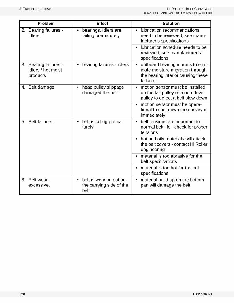
8. TROUBLESHOOTING HI ROLLER - BELT CONVEYORS
HI ROLLER, MINI ROLLER, LO ROLLER & HI LIFE
2. Bearing failures - idlers.
• bearings, idlers are failing prematurely
• lubrication recommendations need to be reviewed; see manu-facturer’s specifications
• lubrication schedule needs to be reviewed; see manufacturer’s specifications
3. Bearing failures - idlers / hot moist products
• bearing failures - idlers • outboard bearing mounts to elim-inate moisture migration through the bearing interior causing these failures
4. Belt damage. • head pulley slippage damaged the belt
• motion sensor must be installed on the tail pulley or a non-drive pulley to detect a belt slow-down
• motion sensor must be opera-tional to shut down the conveyor immediately
5. Belt failures. • belt is failing prema-turely
• belt tensions are important to normal belt life - check for proper tensions
• hot and oily materials will attack the belt covers - contact Hi Roller engineering
• material is too abrasive for the belt specifications
• material is too hot for the belt specifications
6. Belt wear - excessive.
• belt is wearing out on the carrying side of the belt
• material build-up on the bottom pan will damage the belt
Problem Effect Solution
120 P115506 R1
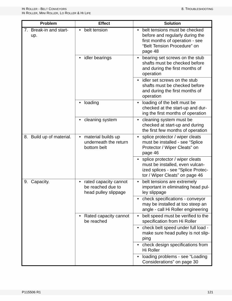
HI ROLLER - BELT CONVEYORS 8. TROUBLESHOOTING
HI ROLLER, MINI ROLLER, LO ROLLER & HI LIFE
7. Break-in and start-up.
• belt tension • belt tensions must be checked before and regularly during the first months of operation - see “Belt Tension Procedure” on page 48
• idler bearings • bearing set screws on the stub shafts must be checked before and during the first months of operation
• idler set screws on the stub shafts must be checked before and during the first months of operation
• loading • loading of the belt must be checked at the start-up and dur-ing the first months of operation
• cleaning system • cleaning system must be checked at start-up and during the first few months of operation
8. Build up of material. • material builds up underneath the return bottom belt
• splice protector / wiper cleats must be installed - see “Splice Protector / Wiper Cleats” on page 46
• splice protector / wiper cleats must be installed, even vulcan-ized splices - see “Splice Protec-tor / Wiper Cleats” on page 46
9. Capacity. • rated capacity cannot be reached due to head pulley slippage
• belt tensions are extremely important in eliminating head pul-ley slippage
• check specifications - conveyor may be installed at too steep an angle - call Hi Roller engineering
• Rated capacity cannot be reached
• belt speed must be verified to the specification from Hi Roller
• check belt speed under full load - make sure head pulley is not slip-ping
• check design specifications from Hi Roller
• loading problems - see “Loading Considerations” on page 30
Problem Effect Solution
P115506 R1 121

8. TROUBLESHOOTING HI ROLLER - BELT CONVEYORS
HI ROLLER, MINI ROLLER, LO ROLLER & HI LIFE
10. Cleaning system failure.
• material build up under the belt
• splice protectors / wiper cleats must be properly installed
• material build up • moisture and water must be elim-inated from the inside of the con-veyor
• reloading flippers/paddles on the tail pulley must be reloading material - replace if necessary
11. Discharge plugging. • conveyor plugging and shutting down
• discharge plug switch must be located to detect a plug and shut down the conveyor immediately
• discharge plug switch must be operational to shut down the con-veyor immediately
• rated capacity cannot be reached due to material building in the discharge spouting
• remove build up and determine the cause
• rated capacity cannot be reached
• check size of the spouting to be sure it is adequately sized for the capacity of the conveyor
• check the spouting angle to be sure it is not too flat an angle and will not flow at the conveyor capacity
12. Freeze down. • belt is frozen down • moisture and water must be elim-inated from the inside of the con-veyor
13. Head Pulley Slippage.
• start-up problem - belt frozen down under the return bottom belt
• moisture and water must be elim-inated from the inside of the con-veyor
• start-up problem - belt stuck down under the return bottom belt
• dust and moisture form a paste that glues the belt to the bottom - moisture and water must be elim-inated
• start-up problem - material build up in the tail section
• cleaning system must be inspected to determine why sys-tem is not cleaning properly
• start-up problem - belt tension not adequate for proper traction
• belt tension must be adjusted to the specifications in “Belt Tension Procedure” on page 48
Problem Effect Solution
122 P115506 R1
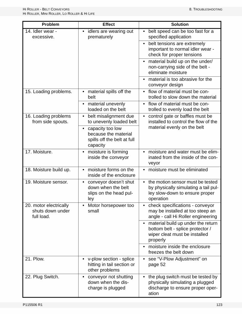
HI ROLLER - BELT CONVEYORS 8. TROUBLESHOOTING
HI ROLLER, MINI ROLLER, LO ROLLER & HI LIFE
14. Idler wear - excessive.
• idlers are wearing out prematurely
• belt speed can be too fast for a specified application
• belt tensions are extremely important to normal idler wear - check for proper tensions
• material build up on the under/non-carrying side of the belt - eliminate moisture
• material is too abrasive for the conveyor design
15. Loading problems. • material spills off the belt
• flow of material must be con-trolled to slow down the material
• material unevenly loaded on the belt
• flow of material must be con-trolled to evenly load the belt
16. Loading problems from side spouts.
• belt misalignment due to unevenly loaded belt
• control gate or baffles must be installed to control the flow of the material evenly on the belt• capacity too low
because the material spills off the belt at full capacity
17. Moisture. • moisture is forming inside the conveyor
• moisture and water must be elim-inated from the inside of the con-veyor
18. Moisture build up. • moisture forms on the inside of the enclosure
• moisture must be eliminated
19. Moisture sensor. • conveyor doesn’t shut down when the belt slips on the head pul-ley
• the motion sensor must be tested by physically simulating a tail pul-ley slow-down to ensure proper operation
20. motor electrically shuts down under full load.
• Motor horsepower too small
• check specifications - conveyor may be installed at too steep an angle - call Hi Roller engineering
• material build up under the return bottom belt - splice protector / wiper cleat must be installed properly
• moisture inside the enclosure freezes the belt down
21. Plow. • v-plow section - splice hitting in tail section or other problems
• see “V-Plow Adjustment” on page 52
22. Plug Switch. • conveyor not shutting down when the dis-charge is plugged
• the plug switch must be tested by physically simulating a plugged discharge to ensure proper oper-ation
Problem Effect Solution
P115506 R1 123

8. TROUBLESHOOTING HI ROLLER - BELT CONVEYORS
HI ROLLER, MINI ROLLER, LO ROLLER & HI LIFE
23. Reloading - cleaning system.
• head pulley slippage • belt tensions need to be adjusted
• excessive reloading at the tail section
• loading problems, velocity of the material is too high, see Section 4.6.
24. Spillage. • excessive reloading at the tail section
• loading problems, bi-directional loaders require a special design - contact Hi Roller engineering
• loading problems, control gate not properly installed, see Sec-tion 4.6.
• loading problems, flow of mate-rial is not directed down the back-plate of the loader - see Section 4.6.
• loading problems, flow of mate-rial is not evenly flowing down the loader backplate - see Section 4.6.
• loading problems, straight down flow of material - see Section 4.6.
• plugging tail section • loading problems, many factors will cause spillage - see Section 4.6.
25. Splice failures. • mechanical splice is wearing out prema-turely
• belt speed and pulley diameter specifications must be followed - contact Hi Roller engineering
• belt tensions are important to normal splice life - check for proper belt tensions
• splice protector / wiper cleats must be installed to reduce wear on the splice - see “Belt Squaring & Cutting” on page 42
26. Splice protector / wiper cleats.
• cleaning system not working well
• splice protector / wiper cleats must be installed on all convey-ors with all types of splices
• splice protector / wiper cleats must be installed to protect and clear the return bottom pan
27. Start-up problems. • belt frozen down • moisture must be eliminated
• head pulley slippage • poor head pulley lagging - new lagging needs to be installed
• belt tensions are too loose
Problem Effect Solution
124 P115506 R1
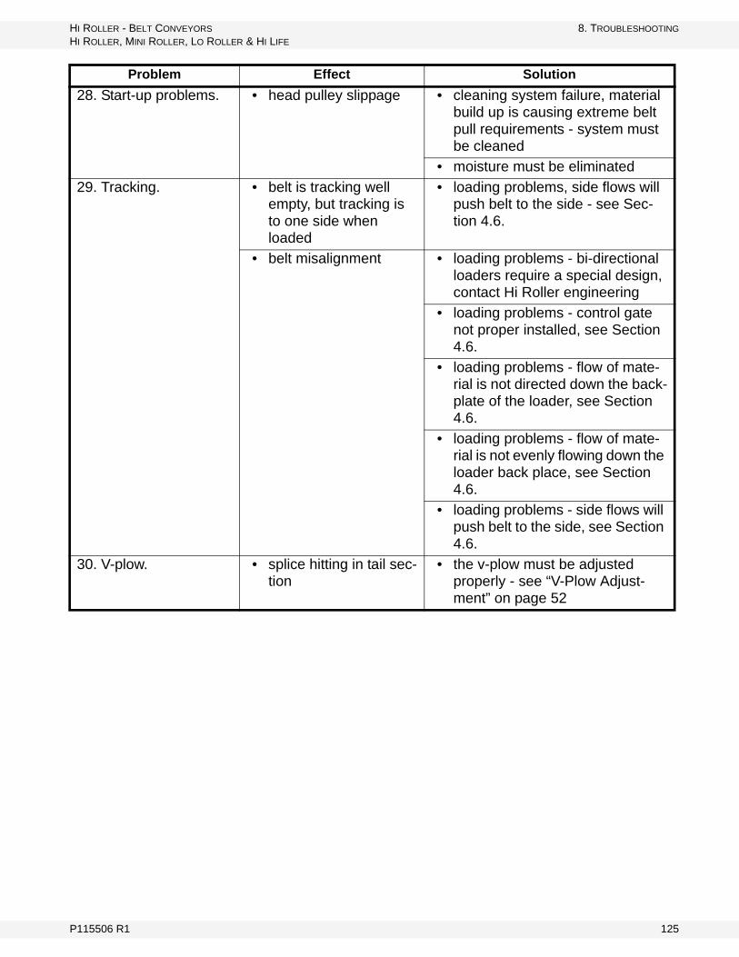
HI ROLLER - BELT CONVEYORS 8. TROUBLESHOOTING
HI ROLLER, MINI ROLLER, LO ROLLER & HI LIFE
28. Start-up problems. • head pulley slippage • cleaning system failure, material build up is causing extreme belt pull requirements - system must be cleaned
• moisture must be eliminated
29. Tracking. • belt is tracking well empty, but tracking is to one side when loaded
• loading problems, side flows will push belt to the side - see Sec-tion 4.6.
• belt misalignment • loading problems - bi-directional loaders require a special design, contact Hi Roller engineering
• loading problems - control gate not proper installed, see Section 4.6.
• loading problems - flow of mate-rial is not directed down the back-plate of the loader, see Section 4.6.
• loading problems - flow of mate-rial is not evenly flowing down the loader back place, see Section 4.6.
• loading problems - side flows will push belt to the side, see Section 4.6.
30. V-plow. • splice hitting in tail sec-tion
• the v-plow must be adjusted properly - see “V-Plow Adjust-ment” on page 52
Problem Effect Solution
P115506 R1 125

8. TROUBLESHOOTING HI ROLLER - BELT CONVEYORS
HI ROLLER, MINI ROLLER, LO ROLLER & HI LIFE
126 P115506 R1
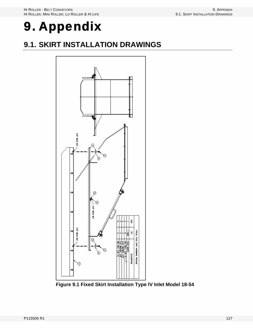
HI ROLLER - BELT CONVEYORS 9. APPENDIX
HI ROLLER, MINI ROLLER, LO ROLLER & HI LIFE 9.1. SKIRT INSTALLATION DRAWINGS
9. Appendix9.1. SKIRT INSTALLATION DRAWINGS
Figure 9.1 Fixed Skirt Installation Type IV Inlet Model 18-54
P115506 R1 127

9. APPENDIX HI ROLLER - BELT CONVEYORS
9.1. SKIRT INSTALLATION DRAWINGS HI ROLLER, MINI ROLLER, LO ROLLER & HI LIFE
Figure 9.2 Swing Skirt Installation Type IV Inlet Model 18
128 P115506 R1
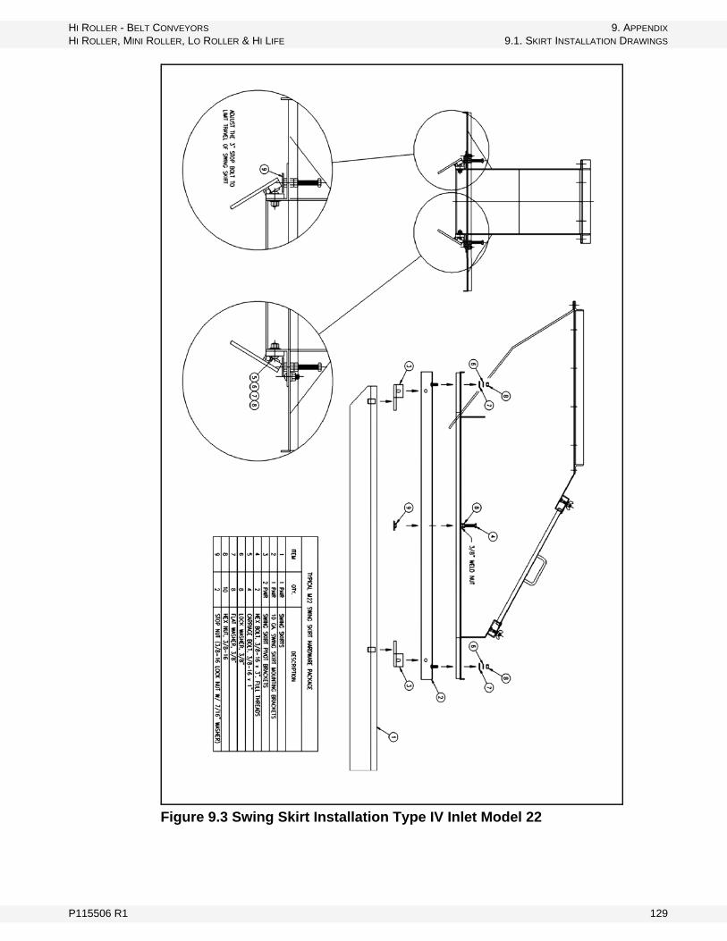
HI ROLLER - BELT CONVEYORS 9. APPENDIX
HI ROLLER, MINI ROLLER, LO ROLLER & HI LIFE 9.1. SKIRT INSTALLATION DRAWINGS
Figure 9.3 Swing Skirt Installation Type IV Inlet Model 22
P115506 R1 129
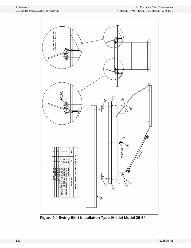
9. APPENDIX HI ROLLER - BELT CONVEYORS
9.1. SKIRT INSTALLATION DRAWINGS HI ROLLER, MINI ROLLER, LO ROLLER & HI LIFE
Figure 9.4 Swing Skirt Installation Type IV Inlet Model 26-54
130 P115506 R1

HI ROLLER - BELT CONVEYORS HI ROLLER, MINI ROLLER, LO ROLLER & HI LIFE
LIMITED WARRANTY AND TERMS OF SALEWARRANTY:
HI ROLLER products are sold with a warranty against defects in material and workmanship for a period of one year from the date of their delivery to the purchaser or their delivery to the carrier in the case of F.O.B. Shipments. HI ROLLER'S warranty shall be limited at HI ROLLER'S option to repair or replacement of any defective parts or components. Such repair or replacement shall be the purchaser's exclusive remedy hereunder, and correction of defects shall constitute complete fulfillment of all obligations and liabilities of HI ROLLER with respect to the product sold hereunder, whether based in contract, tort, or otherwise. The determination of a defective condition shall be made by HI ROLLER in its sole discretion.
LIMITATION OF LIABILITY:
HI ROLLER shall not be liable, in contract, tort, or otherwise, for any special indirect, incidental, or consequential damages, such as, but not limited to, loss of profits, loss of production, or for injury or damage, caused by reason of the instal-lation, modification, use, repair, maintenance, or mechanical failure of any HI ROLLER product. HI ROLLER'S warranties hereunder extend only to the direct customer of HI ROLLER (or to the first user of the HI ROLLER product if the direct customer purchases solely for the purpose of resale). HI ROLLER makes no warranties of any kind with respect to improperly installed product or equipment unless the direct customer of HI ROLLER (or first user, as the case may be) first fully discloses in writing to HI ROLLER the method and details of the proposed installation and the intended use of the product or equipment and HI ROLLER approves in writing of such method and details. HI ROLLER makes no warranties when damage results from the failure to follow instruction decals on certain components of the HI ROLLER system. The purchaser or user of any HI ROLLER equipment shall be responsible for all ordinary maintenance, adjust-ments, and cleaning of the product. In the event that the HI ROLLER product is not properly maintained, all warranties by HI ROLLER are null and void. Certain of the component parts of the HI ROLLER product are purchased from other vendors. HI ROLLER warrants these component parts only to the extent of the vendor's warranties. HI ROLLER shall repair or replace such component parts in accordance with the vendor's warranty policy only if HI ROLLER, in its sole discretion, determines such component parts to be defective.
LOSS, DAMAGE OR DELAY:
HI ROLLER shall not be liable for any loss, damage, detention or delay resulting from any cause beyond its reasonable control, including, but not limited to, fire, strike or other concerted action of workmen, act or omission of any governmental authority or of the purchaser, insurrection, riot, embargo, transportation, shortage, delay or wreck, or inability to obtain labor or material from usual and customary sources.
WARRANTY DISCLAIMER: HI ROLLER MAKES NO WARRANTIES OTHER THAN THOSE STATED HEREIN, AND THESE WARRANTIES ARE EXPRESSLY IN LIEU OF ALL OTHER WARRANTIES, WHETHER EXPRESS OR IMPLIED, INCLUDING BY WAY OF EXAMPLE AND NOT BY WAY OF LIMITATION, ANY WARRANTIES OR MERCHANTABILITY OR FITNESS FOR A PARTICULAR PURPOSE, AND ALSO IN LIEU OF ANY OTHER OBLIGA-TIONS OR LIABILITIES ON THE PART OF HI ROLLER.
P115506 R1 131
HI ROLLER - BELT CONVEYORS
HI ROLLER, MINI ROLLER, LO ROLLER & HI LIFE
MODIFICATIONS:
The prices and terms of this offer are not subject to verbal changes or other agreements unless approved in writing by an authorized representative of HI ROLLER management. No representation or warranty, express or implied, made by any sales representative or any agent or employee of HI ROLLER which is not specifically set forth herein shall be binding on HI ROLLER unless approved in writing by an authorized representative.
TAXES:
Unless otherwise noted, the price does not include any state or local property, sales, use, or privilege tax or license. If any such charge should be enforced by virtue of the transaction described herein, the purchaser agrees to pay the same or reimburse HI ROLLER, as the case may be.
LOSS OR DAMAGE IN TRANSIT:
Any claim for loss or damage to products in transit must be entered and prose-cuted by the purchaser.
RISK OF LOSS:
Delivery shall occur and the risk of loss shall pass to the purchaser upon delivery of the material to the carrier at the point of shipment. Any claim of loss or damage in transit shall be against the carrier only.
GENERAL PROVISION:
The failure of HI ROLLER to enforce any right will not be construed as a waiver of HI ROLLER'S rights to performance in the future. The purchaser may not assign any rights or delegate any performance owed under this agreement without the express written consent of HI ROLLER management.
CLAIM/NOTICE OF DEFECTS:
In the event the purchaser claims that a HI ROLLER product is defective, HI ROLLER shall be given an equal opportunity for inspection, or, upon request, shall be furnished a sample of such product. Any claim must be made within thirty (30) days after receiving the product shipped hereunder. The purchaser shall set aside, protect and hold such products without further processing until HI ROLLER has an opportunity to inspect and advise the purchaser as to the dispo-sition, if any, to be made of such products. In no event shall any HI ROLLER product be returned, reworked, or scrapped by the purchaser without the express written authorization of HI ROLLER.
PATENT RIGHTS:
The purchaser agrees not to violate or infringe the patent rights relating to any HI ROLLER product, or any other patent rights under the control of HI ROLLER or under which HI ROLLER has the right to manufacture or sell. The purchaser also agrees not to contest HI ROLLER'S title to any and all such patent rights, nor the validity or scope thereof. The purchaser assumes liability for patent or copyright infringement when goods or products are made to the purchaser's specifications.
NON-INCORPORATION:
Any terms inconsistent with those stated herein which may appear in the purchaser's formal order or in any proposal for additional or different terms, or any attempts by the purchaser to vary in any degree any of the terms of this offer,
132 P115506 R1

HI ROLLER - BELT CONVEYORS HI ROLLER, MINI ROLLER, LO ROLLER & HI LIFE
are hereby objected to and rejected, but such proposal shall not operate as a rejection of this offer unless such variances in the terms and the description, quantity, price or delivery schedule of the goods or products are deemed a material alteration thereof, in which event this offer shall be deemed accepted by the purchaser without said additional or different terms.
GOVERNING LAW:
All disputes arising out of this offer and purchase order shall be governed by the laws of the State of South Dakota.
JURISDICTION AND VENUE:
The purchaser consents to the personal jurisdiction of the federal and state courts in the State of South Dakota, waives any argument that such a forum is not convenient, and agrees that any litigation relating to this offer and purchase order shall be venued in either the Circuit Court of Minnehaha County, South Dakota, or the Federal District Court, District of South Dakota, Southern Division.
SEVERABILITY
If for any reason any one or more of the provisions contained in this offer are held to be invalid, illegal, or unenforceable in any respect, such invalidity, illegality, and unenforceability shall not affect any other provision hereof and this offer shall be construed as if such invalid, illegal, or unenforceable provision had never been contained herein.
ATTORNEYS' FEES:
The purchaser agrees that in the event there is a dispute between the parties including, but not limited to, arbitration or litigation, that the purchaser shall pay to HI ROLLER all costs involved in such dispute and all other out-of-pocket expenses, including in each case reasonable attorneys' fees and the court costs incurred by HI ROLLER in such dispute.
ERRORS:
Typographical and stenographic errors contained in this offer are subject to correction by HI ROLLER without liability.
INSTALLATION INSTRUCTIONS:
For actual installation criteria and dimensions, do not use any published adver-tising information or catalog dimensions as some components may have been redesigned. HI ROLLER will furnish any information required to install and fit the product for each specific order.
P115506 R1 133

HI ROLLER - BELT CONVEYORS
HI ROLLER, MINI ROLLER, LO ROLLER & HI LIFE
134 P115506 R1

MANUFACTURER: Hi Roller Conveyors (a division of Ag Growth International), 5100 West 12th Street, Sioux Falls, SD, 57107-0514, Phone: 605.332.3200, FAX: 605.332.1107
AUTHORIZED REPRESENTATIVE: (Name and address of the person in the Community authorized to compile the technical file): R&D Manager, Mepu Oy, Mynämäentie 59, 21900, Yläne, Finland
PRODUCT DESCRIPTION: Hi Roller, Hi Life, Mini Roller, and Lo Roller Models
APPLICABLE EUROPEAN DIRECTIVES AND STANDARDS:
ATEX product marking: II 3 GD c T102ºC
The product described in this Declaration of Conformity complies with the Applicable European Direc-tives and relevant sections of the Applicable International Standards. The signature on this document authorizes the distinctive European mark to be applied to the equipment described. A Technical Construction File is available for inspection by designated bodies.
PART NUMBER AND DESCRIPTION:
SERIAL NUMBER:
DATE MANUFACTURED:
Applicable Directives Applicable Standards Certification Method
Machinery Directive 2006/42/EC
EN 12100-1:2003+A1:2009 and EN 12100-22003+A1:2009, EN ISO 3744:1995 and EN ISO 3746:1995, ISO 14121-1:2007, ISO 11684:1995, EN 953:1997+A1:2009, ISO 3600:1996
Self Certified, per Article 12 of the Directive
ATEX Directive 94/9/EC
EN 1127-1:2007, EN 13463-1, EN 13463-5Self Certified, per Article 8 of the Directive
Authorized Signature: Date:
Place of Declaration:
EC Declaration of Conformity
Part of the Ag Growth International Inc. Group
5100 West 12th Street
Sioux Falls, SD 57107
Toll free (US & Canada): 800-328-1785
Phone: 605-332-3200
Fax: 605-332-1107
www.hiroller.com
e-mail: [email protected]
© Ag Growth International 2014