Bellona rapport nr. 6 - 2002 Hydrogen · Bellona rapport nr. 6 - 2002 Bjørnar Kruse Sondre Grinna...
53
Bellona rapport nr. 6 - 2002 Bjørnar Kruse Sondre Grinna Cato Buch Hydrogen Status og muligheter
Transcript of Bellona rapport nr. 6 - 2002 Hydrogen · Bellona rapport nr. 6 - 2002 Bjørnar Kruse Sondre Grinna...

Bellona rapport nr. 6 - 2002
Bjørnar Kruse Sondre Grinna Cato Buch
HydrogenStatus og muligheter

The report´s main sponsors:
Our thanks also go to Eckbos Legater for their economical support.
In order to avoid any misunderstanding: The contents of this report are the sole responsibility of the Bellona Foundation. Our supporters and partners have no responsibility whatsoever in this context.
Bellona’s co-operation with business and industry
In 1998 Bellona launched its co-operation programme aimed at business and industry, called “B7”. Solution oriented and technology optimistic, this environmental programme is based on dialog with those players in the field of business and industry whose ambitions put them on the cutting edge of development.
The B7 programme currently hosts the following partners in co-operation:
NHOUniteamStatoil Phillips PetroleumScandic Hotels StatkraftSASAker RGIAker MaritimeNorway SeafoodsNorcemEiendomssparFred OlsenEnergosOSLMiljøforsikringIndustrikraft Midt-NorgeCOOPBertel O. SteenECO SkrettingMarine HarvestSkeidarSelect Service PartnerBraathensEnergy & IndustryOrganic PowerApplied Plasma PhysicsShellErametPostenWPIFiskebåtrederenes Forbund
THESE CONCERNS REPRESENT BRANCHES, PRODUCTS AND SERVICES THAT WILL BE DESICIVE IN THE STRUGGLE TO DEFINE THE ENVIRONMENTAL DEMANDS OF THE FUTURE.
The B7 programme looks into the important and long term frameworks controlling environment and society, and the partners look upon each other as sparring partners with contra expertise and cutting edge competence in the hunt for environmental and economical improvements.

Published byThe Bellona FoundationNorway: Bellona Norway P.O.Box 2141 Grünerløkka N-0505 Oslo E-mail: [email protected]
Russia, Murmansk. Bellona Murmansk P.O. Box 4310 183038 Murmansk E-mail: [email protected]
Russia, St. Petersburg: Bellona St. Petersburg P.O.Box 4 191023 St. Petersburg E-mail: [email protected]
EU, Belgium: Bellona Europe Rue du Sceptre, 25 1050 Brussels Belgium E-mail: [email protected]
USA: Bellona USA P.O. Box 11835 Washington DC 20008 USA E-mail: [email protected]
URL: http://www.bellona.no/en/
Editor : Bjørnar KruseAuthors: Bjørnar Kruse, Sondre Grinna and Cato Buch.Translated to English by Jenifer Høibråten and Diana Oeding.Language consultants: Marte-Kine Sandengen, Runar Forseth.Design and layout: Puna Productions; Thomas Heiersted
This report is available in: English, NorwegianCopying recommended when source is statedComments to this report are welcomed.
Printed by NFK Digitaltrykk as
ISSN 0806-3451ISBN 82-92318-05-4
Keywords: hydrogen, fuel cells, fuel, future cars, ZEV, energy, energy system, renewable, sustainable,

solutions, we feel that Bellona is unique in its capability to make a constructive contribution with respect to the choice and development of energy sources in the first half of the new century.
This report is principally a survey of the state of technology and technological possibilities. It is simultaneously our hope that it will stimulate others to focus their thinking in terms of challenges and solutions as opposed to problems and obstacles.
In chapter one we describe the vision that lies behind our work with hydrogen. We examine the possibilities and some of the challenges associated with the introduction of hydrogen to the energy and transportation sectors. This chapter also summarises some of the main points of the report. Chapter two discusses the technologies for the production, storage, transportation and use of hydrogen and is fairly technical in nature. Chapters three and four discuss hydrogen in connection with the transportation and energy sectors respectively. In chapter five, we examine the safety aspects of using hydrogen.
It is Bellona’s vision that the oil nation Norway will depart from being a part of the problem to becoming part of the solution. In this report we endeavour to focus on the possibilities and the importance of making the right choices from the very outset.
We would like to thank all who have contributed to this report. Special thanks are extended to Bjørn Gaudernack, Egil Holte, Carl Wilhelm Hustad and Marte-Kine Sandengen.
Bjørnar Kruse, Sondre Grinna and Cato BuchOslo, February 13. 2002
PrefaceIn the course of a century, the world’s consumption of fossil fuels has grown at an exponential rate, increasing by a factor of 20. This has led to a series of environmental problems such as local air pollution, acid rain, the risk of climatic changes and the release of polluting effluents to the soil and water. In controlling 75% of oil reserves and 45% of natural gas reserves in Western Europe, and generating 30% of western European hydroelectric production, Norway is one of the world’s ”great powers” in energy. As a major exporter of fossil fuel and thereby CO2, we have a responsibility towards the international community to develop new and clean sources of energy. The underdeveloped countries of the world cannot be expected to bear the costs of this.
Hydrogen is the most plentiful element in the universe, but it is not easily accessible on the earth. Hydrogen is a neutral energy carrier. This means that the environmental benefit of using hydrogen depends upon how the hydrogen is produced. A renewable energy system using hydrogen as a carrier or for energy storage does not result in harmful pollutants being released to the natural environment. It is possible to eliminate the release of pollutants from mobile combustion, that is, transportation, by replacing the combustion engine with hydrogen-propelled fuel cells combined with electric engines. If we are to overcome the climatic challenges we now face, the introduction of hydrogen as an energy carrier must surely be a clear presupposition.
The Bellona Foundation desires to contribute to the debate over energy use in relation to transportation and climatic change by assuming the role of a knowledgeable and independent advocate of hydrogen. If we are to succeed in tackling the climatic problems the world now faces, it will be paramount to avoid costly detours and dead ends.
With its experience in environmental activism at the grassroots level and in being a promoter for technological
We must choose our path: dead end, precipice or the hyway to the future.
In a global perspective, hydrogen as an energy carrier will be of central importance in diminishing the greenhouse effect and local pollution.
Figure 1

Hydrogen technologyThe launching of hydrogen and fuel cell technology on the market is now in the starting blocks. There are no barriers to the introduction of hydrogen and fuel cells either from a technological perspective or from the vantage point of safety. In fact hydrogen has been produced and utilised industrially for over a hundred years.
Hydrogen can be produced from a number of different sources using different techniques. If hydrogen is produced from coal, oil or natural gas, the ensuing by-products will be harmful to the environment if they are not handled in an environmentally sound way.
The production of hydrogen without the release of pollutants to the environment could become an important export commodity for Norway, representing a refining of natural resources already existing within the country. The use of reformed natural gas with CO2-depositing opens the possibility for large scale export of hydrogen. It is important that the tremendous potential of these possibilities is not ignored. Bellona would therefore like to see the official establishment in Norway of a national research and development program such as is already in existence in other countries.
AbstractThe world now faces tremendous challenges associated with greenhouse gas emissions, climatic change, and the need for a sustainable development. The United Nations Intergovernmental Panel on Climate Change (IPCC) has been studying these problems for over 13 years, and a general consensus has been achieved between researchers, industry leaders and politicians that dramatic reductions in greenhouse gas emissions must be achieved in order to prevent man-made climatic changes.
The deposits of oil in the world are very unevenly distributed. Over 70% of the world’s oil reserves are found in the OPEC countries. Many developing countries use almost their entire export income to import oil, yet it is often these same countries that have some of the best possibilities for utilising solar and wind power as a source of energy to replace their dependence on fossil fuels. In the time ahead it is therefore important that the developing countries do not make large investments that will bind and commit them to the import of fossil fuels. Bellona would argue that the promise held in new hydrogen-based technology gives grounds for optimism for viable solutions to the climatic challenges the world now faces.
Photograph: Electricity and hydrogen are the energy carriers of the future in the transportation and power production sectors.

Fuel cells are now a viable technology that can readily be put into production, while billions are being spent throughout the world on the further development of this technology. Proton exchange membrane fuel cells (PEM) and solid oxide fuel cells (SOFC) appear to be particularly promising areas of fuel cell development. The transportation sectorThe transportation sector within the European Union (EU) is largely based on oil as a propellant fuel. About a third of the total CO2 emissions correspondingly originates from the transportation sector.
In Norway, hydrogen can be produced locally as a renewable energy source using water electrolysis at a competitive price compared to gasoline, with the added benefit of no greenhouse gas emissions. This is because the production of electricity is almost entirely based (99%) on renewable energy.Methanol and natural gas are carboniferous forms of fuel, and are as such, rather than serving as bridge builders to the use of renewables in the transportation sector, dead ends. There is scope for positive improvements in the use of both in the form of real reductions in the emissions of harmful gasses and particles to the local environment, but this helps little or nothing in reducing greenhouse gas emissions. Hence a wise beginning would be to develop an infrastructure that is based on a decentralised production of hydrogen and renewable energy.
Automobiles propelled by fuel cells will become competitive in price to conventional cars once the mass production of fuel cells begins. In the transportation sector, the first fuel cell driven cars, busses and light motorcycles are due to be introduced to the market around 2003-2004.The energy sectorLike the transportation sector, the energy sector is heavily based on the use of fossil fuels. It is estimated that 85% of the world’s commercial energy sales are based on fossil sources of energy.
Optimisation of use and switching from for example coal to natural gas are not enough; consequently a transition to viable renewable sources of energy is necessary to meet the recommendations from IPCC. The production of solar cell panels and wind turbines involved in effecting a changeover to these energy sources would require large amounts of energy, and would hence also lead to an increase in energy consumption. Therefore it will be important to avert greenhouse gas emissions from fossil fuels during the transition phase.
Fossil based power production, notably when utilising methods of handling CO2 such that it is not released into the atmosphere, can be a useful means of providing power in a transition phase. The use of such “CO2-free” forms of fossil energy to produce wind turbines and solar cell panels would be a rational and sensible use of fossil hydrocarbon resources.
Fuel cells generate little noise and are thus well suited for power generation at the local level. The advantage of this is that excess heat can be used for the heating of houses and hot water while simultaneously reducing the need for further expansion and reinforcement of the power grid – as well as reducing loss of power. The electrical power generating efficiency is high, even in small systems and at low load.
One of the first markets for stationary fuel cells are emergency power systems, backup systems that in the event of power outages ensure the continued flow of electricity to hospitals, larger hotels, computer facilities and industry where power outages could endanger human life or lead to great economic loss. Many forms of renewable energy sources such as solar power, tidal waters and wind power cannot provide stability in energy production, and there is often a disparity between the time of production and desired time that the energy is used. Energy systems that are based on these kinds of sources consequently require a means of storing energy, and hydrogen is an energy carrier that is well suited to this. Today there are several such independent energy systems in existence based on renewable energy/hydrogen.
The breakthrough for fuel cells will probably come as replacement of batteries in mobile telephones and portable personal computers. Some people believe that fuel cells will take the place of such batteries within five years. Indeed, this particular market is large and the price it is willing to pay per Wh is greater than in the transportation sector and stationary power generation market. With greater demand, good market grounds for the mass production of fuel cells will of course be present.
SafetyHydrogen is neither more nor less dangerous than most other energy carriers. In some respects, hydrogen has qualities that make it safer than most. Hydrogen is not poisonous, it burns rapidly with low radiation heat, and due to its low density compared to air, has the ability to spread rapidly in open surroundings.
As with other fuels, hydrogen requires the taking of certain precautionary measures, but a hydrogen system can be designed to be equally safe as (if not safer than) for instance the fuel system in gasoline-fuelled motor cars.

PrefaceAbstractIntroduction
1 Visions and challenges 12 From fossils to renewables 12 Ending oil dependency 12 Technological development 12
1.2 Challenges 13 Infrastructure 13 Costs 14 Storage 14 Standards and legal framework 14 Safety issues/lacking knowledge 14 Methanol and natural gas 15
2 Hydrogen technologies 162.1 Hydrogen 162.2 Production 162.2.1 Production of hydrogen based on fossil raw materials 16
Gasification of coal 16 Steam reforming of natural gas 17 CO-shift 17 Separation of CO2 17 Depositing Thermal dissociation 18 Carbon Black & Hydrogen Process (CB&H) 18 Plasmatron 18
2.2.2 Hydrogen production using renewable energy 18 Electrolysis of water 18 Alkaline electrolysers 19 Steam electrolysers 19 Photoelectrolysis 19 Thermal decomposition of water 19 Gasification of Biomass 19 Biological production 20
2.3 Use of hydrogen 21 Fuel cell system 21 Alkaline fuel cells (AFC) 22 Phosphoric acid fuel cells (PAFC) 22 Solid oxide fuel cells (SOFC) 22 Proton exchange membrane (PEM) fuel cells 23 Molten Carbonate Fuel Cells (MCFC) 23 Direct Methanol fuel Cells (DMFC) 23 Regenerative fuel cells 24

2.3.2 Burning hydrogen 24 Combustion technology 24 Hydrogen engines 24 Turbines 24 Hybrids 24
2.4 Storage of hydrogen 25 Compressed hydrogen 25 Liquid hydrogen 25 Metal hydride 25 Methanol 26 Gasoline and other hydrocarbons 27 2.5 Transport of hydrogen 27 Pipelines 27 Transport of liquid hydrogen 28 Roadway transportation 28 Ocean transportation 28 Air transportation 29 The Transportation Sector 30 Land Transport 32
3.1.1 Cars 32 General Motors 32 DaimlerChrysler 33 BMW 33 Toyota 34 3.1.2 Buses 34 3.1.3 Motorcycles 343.1.4 Trains 353.2 Air Transport 353.3 Shipping 363.4 Space travel 373.5 Infrastructure 38 The Energy Sector 404.1 Renewable energy and hydrogen 404.2 Stationary fuel cell systems 404.3 Stand Alone Power Systems (SAPS) 414.4 CO2 removal 424.5 Electronics 42 Safety 44 Hydrogen – Air mix 44 Town gas 45 Fusion / Hydrogen Bombs 45 The Hindenburg Accident 45 The Challenger Accident 45 References 46Appendix 1 50Photographic credits 51

IntroductionThe atmosphere contains greenhouse gases, of which CO2, CH4, N2O and H2O are the primary ones. These gases permit the radiation of the sun to reach the surface of the earth while simultaneously preserving part of the heat that radiates from the earth within the atmosphere. This is called the greenhouse effect. In the same way that the glass in a greenhouse prevents the loss of heat, the greenhouse gases prevent the total escape of heat from the earth’s surface to outer space. Without these gases the average temperature on the earth would be about 35 degrees lower than it is today (in other words, a temperature of about –20 degrees Celsius).
The amount of the various gases in the atmosphere have varied throughout the earth’s history due to volcano eruptions and other natural phenomena. However, over the course of the last two hundred years, mankind has made an ever-increasing impact on the make up of these atmospheric gases. There are many reasons for this: We are disturbing the natural CO2 cycle to a steadily increasing degree. In the course of a few short decades, we have extracted, refined and consumed fossil material that the earth has used millions of years to produce, releasing large amounts of carbon dioxide. Nature partly manages to absorb the ”fossil” CO2 gas by binding it in the sea and in plants through the process of photosynthesis, but large amounts nonetheless end up in the atmosphere.
These releases of fossil CO2 disturb a naturally renewable balance, already unbalanced by the activities of mankind through the cutting and burning of forest and vegetation at a more rapid pace than it is replanted and regrown. In other words, more CO2 is released (through the burning of wood and so on) than the plants are able to take up through photosynthesis. Furthermore, dead biological material (paper, food leftovers, textiles) are left to rot without the presence of oxygen, thereby resulting in a conversion to the climate gas methane (CH4) rather than CO2. Methane’s greenhouse effect is a factor of 21 times higher than that of CO2.
In addition, new chemicals (for example, chlorofluorocarbon gases) have been introduced that also remain in the atmosphere and contribute towards intensifying the greenhouse effect.
I 1988, the World Meteorological Organisation (WMO) and the United Nations Environmental Program (UNEP) established the so-called Intergovernmental Panel on Climate Change (IPCC) (see the IPCC web site: http://www.ipcc.ch) for the purpose of shedding light on the problems connected with the greenhouse effect through a scientific examination of their cause and the social and economic impacts on human society emanating from a possible change of climate.
In 1996, IPCC released its Second Assessment Report (SAR). The information for the report was based on measurements with a statistical uncertainty such that the conclusions of the report were guarded. IPCC’s further work has been aimed at improving the scientific basis needed in order to fully understand the climatic processes.
IPCC’s second overview report, the Second Assessment Report (SAR) was published in 1996 and issued the following (at that time) controversial conclusion:”… that there could be a connection between anthropogenic greenhouse gas emissions and a possible increase in the average temperature of the atmosphere.”
Figure 2Deviations in degrees Celsius of the average temperature measured in the period from 1961—1990 (WG1, 2001). The vertical lines show the annual variation while the thin black posts indicate statistical uncertainty.
���
���� ���� ���� ����
�����
�����������
���
���
����
��
��
�����
���
� ���
���
����
����
����

The conclusions of the Third Assessment Report (TAR) are summarised in the paper of IPCC’s Working Group 1 (WG1, 2001). Earlier assumptions of manmade disturbances to the climate are confirmed. The report investigates and corrects errors and uncertainties: land-based temperature measurements are now corrected for the possible build up of heat as a consequence of urbanisation around the measurement stations; satellite data is checked and corrected from the surface of the ocean and up through the various levels of the atmosphere, and greater account is taken of solar activity – all resulting in a more accurate correspondence between calculations and measurements.
It is now possible to explain much of the temperature changes that have occurred since 1861 when modern temperature measurements first started to be taken at regular intervals. The results of these measurements show that the increase of temperature in the 20th century was 0.6°C on average (with an uncertainty factor of 0.2°C). The increase is 0.15°C higher than estimated in the Second Assessment Report. Parts of the temperature increase in the first half of the century may be ascribed to natural phenomena such as solar activity, volcanic eruptions and El Niño, while the activity in the second half of the century can only be explained by looking at the releases of greenhouse gases caused by human activity. Furthermore, there is a large probability that the decade of the 1990s was the warmest decade and 1998 the warmest year when seen from a 1000 years perspective.
The temperature on land increases on average by about 0.15 degrees per decade, while the temperature of the oceans is increasing at about half that rate. Satellite
measurements taken since 1979 indicate that the temperature in the upper layer of the atmosphere (above 8 km) shows an increase of 0.05 degrees per decade. The temperature differences here are important because they probably reflect the mechanisms driving the earth’s climatic system.
Satellite pictures further show that there is now 10 per cent less snow and ice cover than in 1960, and the duration of time that ice is present within inland lakes at northern latitudes is reduced by about two weeks. It is estimated from tidal water measurements that the surface of the ocean has risen 0.1 to 0.2 m over the course of the last century. This may be explained by thermal expansion and the receding and melting of glaciers on land.
These points notwithstanding, there still remain mechanisms in the earth’s climatic system that are still not completely understood. Some of this uncertainty is in connection with the formation of clouds, solar activity and the influence of cosmic radiation. [Thjell and Lassen, 1999] At the same time, the ability of analysts to model earlier variations in temperature (see figure 2) has improved, due in part to a greater understanding of the physical mechanisms as well as increased computer power to carry out the calculations.
“… no one reading the latest scientific reports published by the IPCC can ignore the mounting evidence of a link between human activity and the world’s climate …”Sir John Browne, CEO, BP Amoco, World Energy, Vol.4, No.1, pp.21, 2001.
Figure 3Comparison between observed temperature changes and calculation models for the period from 1861 to the present. Naturally occurring driving mechanisms and natural phenomena such as solar activity, volcanic eruptions and El Niño, as well as manmade greenhouse gas emissions are taken into account.
���
�������� ���� ���� ���� ���� ���� ����
������
������
���
���
���
���
����
����
����
���
����
������
�����
��
���
���
����
����
����

The concentration of CO2 in the atmosphere is now 363 parts per million (ppm), which is 31% greater than at the beginning of the industrial era, around 1750. The problem is that two thirds of this increase have occurred over the course of the last 50 years. The concentration of CO2 is increasing today at a rate of 1.5 ppm/annum, representing the most rapid increase in 20,000 years. Furthermore, the present day concentration is the highest in 420,000 years, and probably also in the last 20 million years.
In connection with the completion of the Third Assessment Report, IPCC has developed 40 alternative scenarios based on four possible directions of development trends in the coming century. These scenarios assume different combinations of demographic, economic-societal, technological and co-operative development. The Special Report on Emission Scenarios (SRES) is a comprehensive work which will probably form the basis for several prognoses within climatic analysis in the future. The scenarios that SRES covers, range from marked economic growth with limited international co-operation and few environmental protection measures in place, to a “green” development pattern involving extensive international co-operation. [IPCC, 2001] Though no one would assert that any one of these scenarios are necessarily correct, they do nonetheless show general tendencies that point in the same direction.
The prognoses for annual carbon emissions by the gigaton in three different scenarios (A1F1, A1B and A1T) is shown in figure 5. The most optimistic scenario, A1T, will require a strong and committed global co-operation in the years
ahead. The present day development lies somewhere between scenario A1F1 and A1B – which could entail a tripling of annual emissions over the course of the next 60 years. In other words, there is little indication that the climatic problems the world now faces are likely to disappear, or that we can avoid the imposition of stern measures in our part of the world by negotiating our way out of the situation.
According to IPCC, the emissions of greenhouse gases must be reduced by at least 50%, perhaps as much as 60 – 80 %, if dangerous climatic changes are to be avoided. The longer it takes to start achieving reductions in emissions, the greater and more dramatic the reduction will have to be when the issue is finally forced. In order for the developing countries to achieve a certain degree of economic growth, dramatic cuts will be have to be made in the emissions of the industrialised nations. For a wealthy oil-exporting nation such as Norway, this could require that emissions will have to be reduced by up to 90%.
The Kyoto Protocol requires the industrial countries to reduce their emissions of greenhouse gases by 5% by 2010 as compared to 1990 levels. The requirements are differentiated; hence not all countries have to reduce their emissions equally much.
In the future, people will probably conclude that the purpose of “Kyoto” was simply to place the problem of climate change on the global agenda. Ratification of the protocol and the reductions in emissions that this will entail, are not sufficient of themselves to solve the
���
���
������� ���� ���� ����
��� ������������� �����
��������� ��������������
����
����
���
���
���
���
���
���
������
������ ����������������� ����������� ������������� ��� ���������������
����������� ���������� ��
�������������������������
��������������
������� ������
������ ���� ��� ������ ��� ����� ��������������� ���� ��������� �������� �������� �� ������������� ��� ������� ������
��
����� ������ ��� �������������� ������� ������� ������� �
�����
��
��
A comparison between the growth of the six greenhouse gases in the period 1979–1997 and satellite measurements of reflected thermal radiation (i.e. reflected back into space) was recently published in Nature magazine by Harries et al., (2001). Here there is a good correspondence between theory and measurements, and the results are considered to be a strong scientific and measurable confirmation of the greenhouse effect.
Figure 4Increase in the concentration of CO2 in the atmosphere over three centuries.(Source: IPCC, 2001)
Figure 5Different scenarios for CO2 emissions.(Source: IPCC, 2001)
Figure 6Historical variations in temperature (yellow line) and concentration of CO2 (red line).(Source: IPCC, 2001)
��
��
��
��
����� ���� ���� ���� ���� ����
������ ������ ������� �����������������
����
���
���

problems, but they represent the first global political step in the right direction.
At the time that the world made the transition 100 years ago from a largely coal-based energy system to oil, there were many clear advantages to using oil over coal, and this formed the basis for a society based on the combustion engine. Today there is little doubt over the necessity of reducing CO2 emissions to the atmosphere. A renewable energy system based on the use of electricity and hydrogen as energy carriers is an optimal solution.

reduced. Hydrogen would in this case contribute to making renewable energy easier to use.
A country that starts up directly using renewable energy and hydrogen technology would spare itself of many unnecessary, polluting and expensive partial solutions that the industrialised nations must now rid themselves of. Developing countries that today lack a good telecom infrastructure, can, as demonstrated in certain Asian and African countries, directly implement a wireless communications system and thereby omit the use of traditional copper cables. Likewise, it is possible to go directly to a renewable and decentralised energy infrastructure, based on electricity and hydrogen production from local energy sources (sun, wind, etc.).
Ending oil dependencyA further problem with the lopsided distribution of the oil reserves is the uncertainty of continued supply. In the EU, the dependence on foreign oil could grow to 90% by the year 2020. The dependency on oil within the European transportation sector is almost absolute, and this sector accounts for 67% of the demand for oil. Hence alternative sources of energy are necessary also to achieve security of energy supply. Similarly, the distribution of natural gas reserves is also uneven. European Union gas reserves will only last another 20 years if the present rate of consumption is maintained. Furthermore, making a transition from coal and oil to natural gas could be going from one dependence to another. As hydrogen may be produced from a variety of energy sources, hydrogen, like electricity, is a neutral energy carrier that allows the consumer to freely choose the energy source. This also entails the possibility of requiring producers to adhere to environmental protection regulations. The world’s three largest oil importers, the United States, Japan and Germany are also the three leading nations in hydrogen technology.
Technological developmentThe introduction to the market of fuel cell technology is now in the starting blocks. Companies such as International Fuel Cells and General Electric already sell fuel cell systems to supply electricity and heat in private residences, and in the course of 2002, the American concern Coleman will begin the sale of electric generators powered by fuel cells. Because these generators do not pollute, they can also be used indoors. DCH Technologies has started to sell small electrical chargers in Iceland, and has plans to introduce them to the rest of Scandinavia.
Ballard, a leading developer of fuel cells, opened its first fuel cell factory in 2001. The factory manufactures portable power sources and systems for cars and busses. The technology is also immediately applicable to mobile telephones, wheelchairs, portable computers, electric screwdrivers, video cameras, and other portable equipment. Fuel cells also have certain clear advantages over batteries. Compared with a battery of the same
Visions and challengesJules Verne was well updated on new technologies and patents, and loved to portray the use of them. Verne was aware of the fuel cell technology that had been patented in 1839 when he wrote The Mysterious Island, from which the boxed quote is cited. The fuel cell was considered a curiosity by the general public right until the time that it was utilised in space in the 1960s. It is only now, more than 160 years after it was invented, that this technology is finally being taken into use on the earth.
Fuel cells have the potential to revolutionise the energy and transportation sectors. In combination with renewable energy, an energy and transportation system could be developed with much less environmental impact than the present day system. There are however, strong forces working against such a development. In this chapter we present some of the possibilities that arise with the introduction of hydrogen as an energy carrier for fuel cells in the transportation sector and in the power production markets.
From fossils to renewables The deposits of oil in the world are quite unevenly distributed. Over 70% of all oil reserves are in the OPEC countries. Many poor countries utilise almost their entire income from exports in order to import oil, and correspondingly, many poor families use a large portion of their income on fossil fuels such as coal, coke, and kerosene for cooking and light. This in turn leads to polluted in-door air and a series of health problems.
Throughout the chain of production and consumption, oil as a source of energy is impacting the natural environment with pollution. Oil must be extracted, refined, and transported to the place where it will ultimately be consumed. Hydrogen on the other hand can be manufactured in many different ways using different kinds of raw materials, such as biomass for example, or from water with the help of solar energy and it can be produced on site, on demand. Many of the methods of production are also suited for small scale production. Hydrogen could therefore contribute to increased independence and a more just distribution of resources.
Natural conditions within the developing countries often show great promise for the utilisation of “cleaner” energy sources such as solar and wind power; while their energy distribution systems are often underdeveloped – if not non-existent – compared to the industrialised countries. Technologies which utilise solar energy locally therefore ought to have good possibilities for creating the desired infrastructure. The dependency on oil could therefore be
“I believe that one day hydrogen and oxygen, which together form water, will be used either alone or together as an inexhaustible source of heat and light.” From “The Mysterious Island” by Jules Verne, 1874
The cost of importing oil almost exceeds the entire income that the island state Vanuatu in the Pacific Ocean (formerly the New Hebrides) earns from exports.
The population of Vanuatu is just under 200,000 inhabitants, and the government recently decided that the country would endeavour to introduce a hydrogen economy. The ultimate goal is to achieve a total halt in the import of oil by 2010. In order to achieve this, the country desires to enter into technological co-operation with industrialised countries.
Vanuatu desires to produce hydrogen from renewable energy and to utilise modern cars, ships, busses and electric generators that utilise hydrogen or electricity for fuel.
11

14
capacity, the fuel cell as a rule is lighter and lasts longer. Furthermore, it can be refuelled faster.
A number of different makes of busses, cars, and motorcycles powered by hydrogen are due to be launched in 2003-2004, and in the right circumstances these vehicles could quickly capture certain sectors of the market from the combustion motor. Over time as polluting vehicles are replaced by hydrogen-powered vehicles, the air quality in cities will improve and the noise generated by the combustion engine will disappear. People who live in cities will experience an improved quality of life and better health. Thus the concern for climate and environment will also lead to a greater quality of life and wellbeing at the local level.
Nowadays, most commercial goods and merchandise are transported by road in tractor trailers. Even if hydrogen were to be introduced as an alternative source of propulsive power, this heavy transportation of goods still makes a heavy impact on the immediate environment. It is therefore also necessary to decrease the global need for transportation. Making greater use of the possibility of transportation by sea utilising hydrogen-driven ships would also be advantageous. Another possibility might be the building of airships with helium for buoyancy where propulsion would be achieved with the help of electric motors that are powered by electricity from solar panels during the day, and by hydrogen fuel cells during the night. The hydrogen needed for propulsion at night would be manufactured using energy generated by the surplus production from the solar panels during the day. Airships such as these would not need a crew and could be operated via remote control to safely and efficiently transport goods. In Germany there are three companies that are either about to or have already started to build airships that utilise a conventional power train. One of these companies is Zeppelin, the same company that built the ill-fated airship Hindenburg which crashed in New York in 1937 (Read more about hydrogen and airships in Chapter 5).
The changes within the power supply market will probably be even more radical. Developments over the last hundred years have been characterised by the aim of building the largest possible units in order to benefit from the advantages of operation on a large scale in the form of higher efficiency and cost savings with respect to manpower and capital expenses. This has led to the expansion of the transmission lines to facilitate the transport of electricity, and the release of contaminants to the environment has become centralised. The expenses of expanding the power grid between the major producers and the consumers have been paid by the consumers.
A renewable energy system based on hydrogen would preclude any pollution and contamination from the power stations, and the idea of building large entities would become obsolete. Fuel cells are efficient, even in
small entities, and they are very scaleable. Hence a single installation can easily be expanded to higher output by increasing the number of fuel cells.
Another advantage of fuel cells is that the efficiency is quite high even at a low load. This is particularly important in power production. Furthermore, fuel cells do not require constant monitoring. They can be monitored by computers and/or be remotely controlled. The low-noise fuel cell power plants may without further consideration be placed within inhabited areas. Excess heat from these localised plants can be utilised for heating water for household
use, heating residences, and in industrial processes, further increasing energy efficiency. The placement of small power plants in decentralised locations close to consumers reduces the need to increase the carrying capacity of the existing electricity grid. This affords great economic savings, and also halts the large-scale razing of nature brought on by power grid expansion. Short distances between consumers and point of production will also result in reduced transmission losses. The loss of electricity in the power grid is a considerable expense, especially in overloaded grids and where power is transported over long distances.
Many residences and firms will install fuel cells for power and hot water supply. Fuel cells, along with windmills, geothermal heat and solar cell panels can bring about self-sufficiency in heating, electricity and transportation fuel. So-called “smart software agents” can obtain the best possible price when buying or selling electricity on the net, and ensure the production of hydrogen as fuel for automobiles and other vehicles.
In a scenario such as this, there would be many suppliers of energy on the market, in contrast to today where the suppliers are few but very large.
ChallengesInfrastructureThe lack of infrastructure is used as a major objection to the use of hydrogen. The first hydrogen-powered cars will probably be sold as fleet vehicles to companies covering a limited geographical area, for example taxis, busses, local council vehicles, and courier cars. The absence of “hydrogen filling stations” on every corner would not present a problem for these types of vehicles. The introduction of hydrogen as a propellant fuel on a larger scale and for the use in private automobiles would however require an established infrastructure. Chapter 3 examines how this can be accomplished in Norway.
The German auto maker BMW has equipped their first hydrogen cars with tanks for both hydrogen and gasoline such that the engine automatically changes over from
Hydrogen and fuel cells satisfy all requirements for an environmentally friendly vehicle with respect to emissions.

hydrogen to gasoline in the event that the hydrogen tank should run dry. This is technically possible because the cars utilise an ordinary combustion engine. However, BMW assumes that there will be a sufficient number of German hydrogen stations in the course of the next few years.
CostsThe high cost of hydrogen equipment and fuel cells has been a barrier to further advance in the use of hydrogen technology. One of the most expensive elements in the production of fuel cells is platinum (used as a catalyst).
Today, less than one gram of platinum is needed per kW (at a cost of 15 USD/gram as of October 30, 2001). Partnership for a New Generation of Vehicles (PNGV), an American co-operative venture between government and car manufacturers, aims for a goal of 0.2 gram of platinum/kW by the year 2004. PNGV is furthermore working to achieve a number of cost reductions in the necessary components within fuel cell systems. Ford and Toyota are well known for their long experience in introducing new technology and in reducing costs by means of mass production, and both are seriously engaged in the further development of hydrogen technology.
A study carried out by Ford shows that the price of fuel cells could come down to match that of the combustion engine [Ford 1999]. Indeed, one of the major challenges today for fuel cells and other hydrogen technology is making the transition from the prototype stage into mass production.
StorageHydrogen contains a lot of energy per unit of weight while the content of energy per unit of volume is quite low. This poses a potential problem in terms of storing large amounts of hydrogen in a small space. The storage of hydrogen is a topic of extensive research and development. The traditional means of storage such as pressure tanks and cryogenic tanks have improved dramatically, and a
number of new storage technologies are currently under development. Indeed, for certain applications the existing technology is already good enough. Storage technologies are discussed in Chapter 2.
Standards and legal frameworkThe early introduction of international standards for all countries is important in avoiding unnecessary extra costs such as redesign as a consequence of diverging standards and safety requirements. Standardisation would also simplify the international trading of hydrogen technology. In this vein, the International Organisation for Standardisation (ISO) has established a technical committee for hydrogen technology, the ”ISO/TC 197 – Hydrogen technology”.
In March 1999 the first hydrogen standard was published: - ISO 13984 “Liquid Hydrogen – Land vehicle fuelling system interface”.
In addition, the following seven standards are presently under development: - ISO 13985 ”Liquid Hydrogen – Land vehicle fuel tanks”- ISO 13986 ”Tank containers for multimodal transportation of liquid hydrogen”- ISO 15594 ”Airport hydrogen fuelling facility”- ISO 15866 ”Gaseous hydrogen and hydrogen blends – Service stations”- ISO 15869 ”Gaseous hydrogen and hydrogen blends – Land vehicle fuel tanks”- ISO 15916 ”Basic requirements for the safety of hydrogen systems”- ISO 17268 ”Gaseous hydrogen – Land vehicle fuelling connectors” [Bose, Gingras 2000].
Another co-operative effort is the European Integrated Hydrogen Project (EIHP) to develop regulations for hydrogen-powered vehicles so as to co-ordinate development of the technology in Europe. EIHP is a co-operation between European car manufacturers and government agencies.
Safety issues/lacking knowledgeToday there are no technical and/or safety barriers that prevent the use of hydrogen for fuel in the transportation sector, or as a medium for the storage and transportation of energy. It is possible to manufacture and utilise hydrogen just as safely as with today’s gasoline systems.
Studies in Germany, Norway and Canada on the relationship of the general public to hydrogen show that most people associate hydrogen with environmental conservation. Other studies undertaken while trying out hydrogen busses as an option for public transport indicated that an overwhelming majority of people is positive to the idea of hydrogen as a form of fuel. However, most have little or no knowledge of hydrogen or fuel cell technology, and hence a comprehensive educational campaign must be carried out.
In the period from 1896 to 1928, eight attempts were made to fly from Spitsbergen to the North Pole in balloons and airships. Amundsen and Nobile reached the North Pole in 1926 with the airship Italia. Virgohamna (photo) at Spitsbergen was the base for Andrée’s attempt to reach the North Pole in the hydrogen balloon Örnen in 1896-1897 and for Wellman’s three attempts between 1906 and 1909 to reach the North Pole with the airship America. Both built facilities at Virgohamna for chemical hydrogen production and produced hydrogen with iron and sulphuric acid.

16
While the hydrogen bus “Nebus” was being tried out in Oslo, a questionnaire was circulated in which it came out that the majority of those who had any knowledge of hydrogen had learned about it in school. Consequently, the school system should receive high priority as an area in which to concentrate the dissemination of information. Of all the groups in society, it is the youth who are least afraid of trying out new things, as may be clearly seen in the expansion of technologies such as mobile telephones and Internet.
It is also important to educate specialists in the field of hydrogen and fuel cell technology. The lack of qualified personnel today is a limiting factor for further development. The fuel cell cars will have electric motors; hence the expertise that has been developed at those service departments and stations that have specialised in electric cars can for the most part be easily transferred. Work shops and garages must be ventilated and approved for hydrogen. Nor should unfamiliarity in handling this type of fuel at filling stations be any hindrance: refuelling with hydrogen gas is accomplished the same way as tanking up on natural gas, and there are already several such filling stations in operation in a number of different places.
Methanol and natural gasIn some quarters, methanol and natural gas have been presented as bridge builders towards the hydrogen age. However, methanol and natural gas are both carboniferous fuels, and for example, when used in fuel cells, CO2 is generated that is difficult to separate. An expansion of methanol or natural gas infrastructure for the transportation sector does not make sense with a view to achieving reductions in greenhouse gases. Besides, methanol and natural gas could become a serious obstacle to the introduction of hydrogen as a fuel.
A methanol-driven fuel cell would at best reduce CO2 exhausts by 30-40% as compared to a conventional gasoline-driven automobile. The hybrid cars that are already available on the market and combustion engines with variable compression (not yet in production), are supposedly comparable to methanol fuel cell cars with respect to reduced CO2 exhausts. [Automotive World, March 2000]
Oil companies with tunnel vision might cling to methanol infrastructure and methanol production as a means of preserving dominance in the fuel market or as an expansion to new markets, but environmental conservation it is not.
Natural gas busses would be even worse. Compared to an ordinary diesel bus, a natural gas bus gives off even greater greenhouse gas emissions. This is in part due to the release of non-utilised methane through the exhaust pipe. While natural gas busses certainly do represent a positive improvement in terms of the release of particles to the local environment, in a global perspective there is no improvement.
See chapter 3 for more information on methanol and other hydrocarbons.
2 large natural gas reformers, which supply a million cars with hydrogen, would result in one million exhaust-free cars. This could be an economical way of introducing hydrogen as an energy carrier on a large scale.
Many renewable energy sources vary considerably on a daily and seasonal basis. An energy system based on such sources must be able to store energy to balance out variations. Correspondingly, the great distances usually seen between the energy sources and the consumers necessitates transportation of the energy. For both these purposes it may be practical to convert the energy to hydrogen.
A renewable energy system must also include a renewable transportation system. Since transportation now consumes approximately a third of the energy needs of industrialised countries, it is obvious that renewable hydrogen will be an important fuel in the future. Hydrogen from biomass has the potential to compete with hydrogen produced from natural gas in certain areas [PYNE 8/1999]. Two independent studies (Ford 1998 and NHE 1997) show further that hydrogen produced at a fuel station by water electrolysis based on electricity from Norwegian hydropower would be cheaper than gasoline at current taxes.
There are many ways of producing hydrogen. The following describes some of the most common techniques of producing hydrogen from hydrocarbons. There is further discussion surrounding new techniques which could be of consequence, as well as some interesting methods for producing hydrogen from renewable energy. Some of these are well-proven commercial techniques, while others, such as photobiological hydrogen production, are technologies under development.
It should be noted that as an energy carrier, hydrogen is “neutral” as to the actual source of energy. One could, for instance, envision large scale electrolysis based on nuclear power. Due to the environmental problems surrounding nuclear power, such a solution would, in our view, defeat the purpose.
2.2.1 Production of hydrogen based on fossil raw materialsStrongly simplified, the majority of the processes described below are based on heating up hydrocarbons, steam and in some instances air or oxygen, which are then combined in a reactor. Under this process, the water molecule and the raw material are split, and the result is H2, CO and CO2. In other words, the hydrogen gas comes from both the steam and the hydrocarbon compound. Another method is to heat up hydrocarbons without air until they split into hydrogen and carbon.
Gasification of coalGasification of coal is the oldest method of producing hydrogen. In the old gas plants, the original gas piped in to
Hydrogen technologies2.1 HydrogenThe hydrogen atom is made up of a nucleus with positive charge and one electron. The hydrogen molecule is made up of two hydrogen atoms and is the most basic of all molecules. At room temperature and under normal pressure, hydrogen is a colorless, odourless and non-poisonous gas which is lighter than air and helium. Hydrogen burns with a pale blue, almost invisible flame. At temperatures under –253 ºC hydrogen is in a liquid state. [Brady 2000] [Kofstad 1995]
Hydrogen means “water creator”, it was identified as a base material by H. Cavendish (1731-1810). Hydrogen is the most common base material in the universe and is the main substance found in the sun and the stars. On earth practically all hydrogen is in a compound form with other elements. It reacts very readily with oxygen to create water. The water molecule consists of two hydrogen atoms and one oxygen atom. The oceans of the world therefore make up a huge storeroom of hydrogen. Hydrogen is also an important part of all organic matter. This includes vegetable, animal, and fossil matter. In the environment H2 can be freely found in volcanic gasses, but its lightness allows it to escape beyond the earth’s gravitational forces.
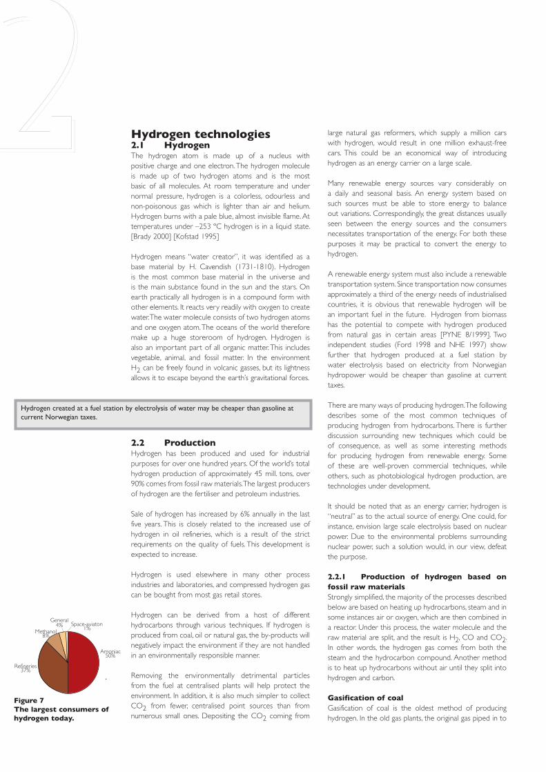
2.2 ProductionHydrogen has been produced and used for industrial purposes for over one hundred years. Of the world’s total hydrogen production of approximately 45 mill. tons, over 90% comes from fossil raw materials. The largest producers of hydrogen are the fertiliser and petroleum industries.
Sale of hydrogen has increased by 6% annually in the last five years. This is closely related to the increased use of hydrogen in oil refineries, which is a result of the strict requirements on the quality of fuels. This development is expected to increase.
Hydrogen is used elsewhere in many other process industries and laboratories, and compressed hydrogen gas can be bought from most gas retail stores.
Hydrogen can be derived from a host of different hydrocarbons through various techniques. If hydrogen is produced from coal, oil or natural gas, the by-products will negatively impact the environment if they are not handled in an environmentally responsible manner.
Removing the environmentally detrimental particles from the fuel at centralised plants will help protect the environment. In addition, it is also much simpler to collect CO2 from fewer, centralised point sources than from numerous small ones. Depositing the CO2 coming from
Hydrogen created at a fuel station by electrolysis of water may be cheaper than gasoline at current Norwegian taxes.
Figure 7The largest consumers of hydrogen today.
2
�������������
����������
���������
����������
���������������

18
cities was produced this way. This gas contained up to 60% hydrogen, but also large amounts of CO. Typically, the coal is heated up to 900ºC where it turns into a gaseous form and is then mixed with steam. It is then fed over a catalyst – usually nickel.
There are also other more complex methods of gasifying coal. The common factor is that they turn coal, treated with steam and oxygen at high temperatures, into H2, CO and CO2. In addition, sulphur is released from the raw material and creates sulphur and nitrogen compounds. As with CO and CO2, these compounds must be handled in an environmentally friendly way.[Winter et al 1988] Today there are large coal gasification plants in Europe, South Africa and the USA, and technologies for gasification of coal is the object of a great deal of R & D within the coal industry.
Steam reforming of natural gasSteam reforming of natural gas is currently the cheapest way to produce hydrogen, and accounts for about half of the world’s hydrogen production. Steam, at a temperature of 700-1000 ºC, is fed methane gas in a reactor with a catalyst, at 3-25 bar pressure.
In addition to the natural gas being part of the reaction process, an extra 1/3 natural gas is used as energy to power the reaction. New methods are constantly being developed to increase the efficiency, and maximising the heat process makes it possible to increase the utilisation to over 85% and still make a profit.[Gaudernack 1998]
A large steam reformer which produces 100,000 tons of hydrogen a year can, roughly speaking, supply one million fuel cell cars which have an annual average driving distance of 16,000 km. Steam reforming of natural gas produces 7.05 kg CO2 per kilogram of hydrogen. [Princeton University 1997]
There are two main types of steam reformers for small scale hydrogen production: conventional, down-sized reformers, and specially constructed reformers for fuel cells. The latter operates under lower pressure and temperature than conventional reformers, and are more compact.
Work is under way to build a modified steam reformer with a built-in CO2 remover. This will make it possible to produce hydrogen at a lower temperature than regular steam reformers. These reformers will reduce the cost of hydrogen production by 25-30% compared to conventional technology, mainly due to reduced capital and operating expenses. [US DOE, Hydrogen Program 2000]
Autothermal reforming of oil and natural gasBurning hydrocarbons with reduced amounts of oxygen is called partial oxidation. Autothermal reforming is a combination of partial oxidation and steam reforming. The term reflects the heat exchange between the endothermic
steam reforming process and the exothermal partial oxidation. The hydrocarbons react with a mixture of oxygen and steam in a “thermo reactor” with a catalyst.
Norsk Hydro’s “Hydropower“ concept, which is based on this process, uses air instead of pure oxygen in the reforming, both because of cost and because the nitrogen in the resulting feed gas has a lower burning temperature and reduced flame velocity. The feed gas can therefore be used in turbines developed for gas power plants.
The low fluidity and often high content of sulphur in heavy hydrocarbons prevent using the steam reforming process. Instead, they are subjected to partial oxidation, or autothermally in a flame reaction adding steam and oxygen at 1300 – 1500º C (i.e. The Texaco process). The relative amount of oxygen to steam is controlled so that the gasification process requires no external energy.
CO-shiftThe processes described above produce gas with a high content of carbon monoxide – CO. It is therefore necessary to put the gas through the CO-shift process to increase the content of hydrogen. The shift reaction (see sidebar) is a two-step process to achieve the most complete reaction between CO and steam. Initially steam is added in a high-temperature step (300-500ºC), followed by a a low-temperature step (200ºC), with different catalysts in the two steps.
Separation of CO2Each of the processes described above produces CO2 in addition to H2. To separate hydrogen and CO2, it is common to use amine based absorption processes. This is conventional technology. Methods based on selective membranes or sorbents are under development.
DepositingTo avoid having the fossil CO2 released into the atmosphere, it must be deposited permanently. Possible depositories include empty oil and gas reservoirs, or underground water reservoirs, called aquifers. A study carried out for the EU Commission in 1996 shows that the capacity for depositing in Europe is 806 billion tons of CO2. The majority of this space is found on the Norwegian shelf, where there is room for 476 billion tons in aquifers and 10.3 billion tons in empty oil and gas reservoirs. It would therefore be possible to deposit emissions from all the power plants in Western Europe for many hundreds of years.[Holloway et al. 1996] Since 1996, Statoil has deposited one million tons annually in an aquifer (the Utsira formation) at the Sleipner field. This is CO2 which has been removed from natural gas to meet the sales specifications of Continental Europe. CO2 can also be used instead of natural gas for pressure support
Natural gas consists mainly of methane, mixed with some heavier hydrocarbons and CO2. By applying high temperature steam to the methane, hydrogen and carbon oxides are created.
Steam reforming is the most common method of producing hydrogen today.
The formula for the chemical reaction is:CH4 + H2O -> CO + 3H2
And for the following “shift reaction”:CO + H2O -> CO2 + H2
Which produces:1 mol methane =-> 4 mol hydrogenThe percentage of hydrogen from water is 50%.
To avoid releasing fossil CO2 into the atmosphere, a permanent depository is needed.

in oil production. This has been done on a large scale in American fields. It is also possible to deposit CO2 in the deep ocean, but there is great uncertainty as to the storage time and environmental impact. We therefore do not consider this to be a viable option.
Thermal dissociationBy heating up hydrocarbon compounds without oxygen at very high temperatures, it is possible to separate the hydrogen and carbon. Approval of this type of process with regard to greenhouse gas free hydrogen production, assumes permanent depositing of the carbon. The formula for this process using methane as fuel is:
CH4 -> C + 2H21 mol methane -> 2 mol hydrogen
Carbon Black & Hydrogen Process (CB&H)Carbon Black is a super pure carbon (soot) which is used in car tire production, and as a reducing material in metallurgic industries. Obviously, such use cannot be considered as permanent depositing of fossil carbon, as most of it would oxidise at a later stage and thus be released to the atmosphere. However, the Carbon Black powder may be deposited safely, needing far less space and other considerations than the CO2 gas.
Kvaerner developed a process called the “Kvaerner Carbon Black & Hydrogen Process “ (KCB&H). The first commercial plant based on this process started production in June of 1999. The Kvaerner process is emission-free, while the traditional production methods for Carbon Black are extremely polluting. The by-product from this process is hydrogen.
In a high temperature reactor, the correct amount of heat for splitting the hydrogen compounds is supplied by a plasma burner, which utilises recycled hydrogen from
the process as plasma gas. A heat exchange system heats up the process flow. Power usage in Kvaerner’s CB&H is theoretically 1 kWh/m3 H2, but in reality requires over double the amount because of the high reaction temperature. The surplus energy can, to a certain degree, be recycled in the form of steam. As raw material this process may utilise hydrocarbon compounds ranging from light gases to heavy oil fractions.[Hildrum 1998]
PlasmatronAt the Massachusetts Institute of Technology (MIT), researches are developing a reformer which uses plasma for reformation of hydrocarbons. The advantage of a plasma reformer is that it can use all forms of hydrocarbons, including heavy oil fractions. In addition, the plasma reformer can operate in pyrolytic mode (thermal degrading of organic material without air or oxygen like the KCB&H described above), turning the carbon into soot. This eliminates the formation of CO2. Plasma technology allows for more compact and lighter designs than traditional reformers because the reaction occurs much faster.
MIT is studying the use of the plasma reformer in both the pyrolytic, partial oxidation and steam reforming mode. MIT’s “Plasmatron” operates at temperatures of over 2,000º C. Hydrogen yield is 80-90%. The main disadvantage of plasma reformation in general, is its dependency on electrical power. MIT hopes to reduce the amount of electricity to 5% of the fuel’s combustibility. The current need is approximately 20%. [L. Bromberg et al. 1997/1998]
2.2.2 Hydrogen production using renewable energyAs mentioned previously, hydrogen is found in large amounts on earth bound in organic material and in water. Over 70% of the earth is covered with water. The percent of hydrogen in water measured by weight, is 11.2%. There is definitely an abundant supply. The advantage in using hydrogen as fuel is that, during combustion, it binds itself to the oxygen in the air, and creates water. Hydrogen is therefore totally renewable, and with this in mind, it could be said that we only “borrow” the hydrogen.
Breaking down water to hydrogen and oxygen is a process that requires energy. Heat, electricity, light or chemical energy can be used for this purpose. If renewable energy is used, the resulting hydrogen will also be a clean and renewable energy carrier.
In the following we will describe some of the processes which can be used to achieve this. Biomass can also be used as raw material in the processes described for fossil fuels, and this will also be covered.
Electrolysis of waterWater electrolysis is splitting water into hydrogen and oxygen. An electrolyser is a device for electrolysis. Water
Making your own fuel at home. Here a Ford Focus is being filled with hydrogen from a small gaarage electrolyser (grey can in front).

20
is subjected to electrical power and the result is hydrogen and oxygen.
2H2O + energy -> 2H2 + O2
This is the opposite reaction of what happens in a fuel cell (see 2.3.1). It is common to classify electrolysers according to the electrolyte it uses. Several cells are connected to achieve the desired capacity, just as with fuel cells. Some common electrolysers are as follows:
Alkaline electrolysersIn alkaline electrolysers a liquid electrolyte is used – typically a 25% potassium hydroxide solution. Hydrogen production using alkaline electrolysers is long-established in Norway. At Norsk Hydro, industrial water electrolysis of hydrogen for the production of ammonia was carried out from 1928 to 1988.
Norsk Hydro Electrolysers (NHE) is today a leading producer of alkaline electrolysers. Some of NHE’s electrolysers have an efficiency of over 80% (high heating value). Efficiency is an important factor in electrolysis because the use of energy (~4.5 kWh/NM3H2) makes up a significant portion of the costs at an electrolysis plant. (How much will depend on the cost of the electricity. NHE estimates approximately 2/3 of operating expenses as a rule of thumb.) Electrolysers are most effective when running on a low production rate, due to low current density. Optimum economy of operation will depend both on current density, cost of production materials and the demands for H2 production.
NHE and Gesellschaft für Hochleistungwasserelektrolyseure (GHW) have developed a compact electrolysis system that can produce hydrogen equivalent to the energy supply of a standard gasoline station. These electrolysers operate under pressure, and the product is hydrogen under moderate pressure (30 bar).
Another leading manufacturer of electrolysers, Stuart Energy, has also made a small prototype of a home garage electrolyser with compressor and everything else inside a small gray box. Polymer electrolyte membrane (PEM) electrolysersAnother type of electrolyser utilises polymer membranes as electrolytes (PEM). Much of the heavy technological development which is currently going on in PEM fuel cells can be transferred to the electrolysers, which will probably benefit from the mass production of PEM fuel cells.
Several PEM electrolysers are already being sold today, even though this is relatively new technology compared to alkaline electrolysers. Efficiency factors for PEM electrolysers up to 94% are predicted, but this is only theoretical at this time. Today, the efficiency factors for PEM electrolysers are lower than for the best alkaline electrolysers. PEM electrolysers function very well with renewable energy systems where the amount of electricity varies greatly.
Generally speaking, PEM electrolysers are best suited for small plants, especially plants with varying output, while alkaline electrolysers are clearly an advantage in larger systems which are connected to the power grid.
Steam electrolysersA third type of electrolysers is the so-called steam electrolysers. These use a ceramic ion-conducting electrolyte. Steam electrolysers can reach a very high efficiency factor, but are currently not commercially feasible.[NYTEK 2000] A tubular steam electrolyser, which should also be able to be run in a fuel cell stack (fuel cells connected in a series), are under development at Lawrence Livermore National Laboratory. Another type of steam electrolyser is the German “Hot Elly”; this system can reach an efficiency of 92%. [NREL 2000]
PhotoelectrolysisInstead of first converting sunlight to electricity and then using an electrolyser to produce hydrogen from water, it is possible to combine these two steps. The photovoltaic cell combines with a catalyst, which acts as an electrolyser and splits hydrogen and oxygen directly from the surface of the cell. This can quite realistically be a commercially viable means of producing hydrogen. The advantage with these systems is that they eliminate the cost of electrolysers and increase the systems’ efficiency. Tests performed outdoors with silicon based cells have shown an efficiency of 7.8% in natural sunlight. Research is being done to increase the efficiency factor and the life span for such cells.[DOE 2000], [Turner 1999]
Thermal decomposition of waterIn a thermal solar power plant with a central collector such as Solar Two, a 10 MW power plant in California, the temperatures can reach over 3,000ºC. By heating water to over 2,000ºC, it is broken down into hydrogen and oxygen. This is considered to be an interesting and inexpensive method of producing hydrogen directly from solar energy. Research is also being done on the use of catalysts to reduce the temperature for dissociation. One central problem is the separation of gases at high temperatures to avoid recombining. The efficiency factor is uncertain.
Gasification of BiomassHydrogen can also be produced by thermal gasification of biomass such as forestry by-products, straw, municipal solid waste and sewage. The amount of hydrogen in biomass is about 6-6.5 weight percent compared to almost 25% for natural gas.[PYNE 8/1999] The processes involved in producing hydrogen from biomass resemble the processes in production from fossil fuel. Under high temperatures, the biomass breaks down to gas. The gas consists mainly of H2, CO and CH4 (methane). Steam is then introduced to reform CH4 to H2 and CO. CO is then put through the shift process to attain a higher level of hydrogen. The by-product from this process is CO2, but CO2 from biomass is considered “neutral” with respect to greenhouse gas, as it does not increase the CO2 concentration in the
High/low heating values and efficiencyThe heating value, i.e. the amount of heat energy that can be derived from a fuel by burning it, is rated with a high and a low value. The high value denotes the total energy of the fuel, while the low value takes into consideration that the resulting product gas can be condensed into water, subtracting this condensation energy (latent heat) component. When calculating the efficiency in a fuel cell, the low heating value is normally used, i.e.: electrical energy produced / low heating factor * 100%. In the electrolysis process, the high heating value is usually used.
Two atmospheric electrolysers, each at 200 Nm3/h(photo: Norsk Hydro)

atmosphere. The mixed gas can also be used in fuel cells for electricity production. Compared to conventional processes for production of electric energy from biomass or waste, integrated gasification fuel cell systems are preferable. Electrical efficiency over 30% is possible for these systems. This is not possible using traditional technology. [NYTEK 2000]
Gasification reactors have been developed to produce methanol from biomass. Several of these can be used in hydrogen production. Especially those that use air instead of oxygen are economically feasible. [Ogden & Nitsch 1993] Another process which is under development at NREL in the USA is to put the biomass through pyrolysis where it turns into bio-oil. This oil can be converted into hydrogen and CO2 by reforming. The bio-oil, as with fossil oil, is made up of different elements. These can be broken
down into various valuable products, including hydrogen. Another advantage with bio-oil is that it reduces the need for transport of large quantities of biomass. Smaller pyrolysis centres which make bio-oil can be set up near the biomass, and the bio-oil from these can then be transported to a hydrogen station by an oil tanker truck, for example. The bio-oil can be stored at the station and reformed to hydrogen as needed. This, in addition to the sale of by-products, can make producing hydrogen from biomass competitive with producing hydrogen from natural gas at large plants. Where there is no infrastructure for natural gas, the bio-hydrogen may be cheaper than hydrogen from natural gas.
Biological productionPhotosynthesis is the basis for almost all life on earth. The first step in the photosynthesis involves splitting water into oxygen and hydrogen. The hydrogen is then mixed with carbon dioxide and turned into carbohydrate. Decomposition of water using solar power is obviously not
a new idea, but in fact a process which started practically before the age of dawn, and which was the basis for the creation of the earth’s atmosphere, and consequently the basis of almost all life on this planet. It is also the most common biochemical process on earth. Plain sunlight cannot directly break water down, but with the help of special pigments in organisms that engage in photosynthesis, the energy in sunlight can be utilised. As mentioned earlier, hydrogen which is created by photosynthesis is usually spontaneously changed into a carbohydrate. But there are some micro-organisms which are capable of releasing hydrogen freely into the air. This was discovered in 1896 when a culture with the blue-green algae Anabaena was stored in a sealed jar and exposed to sunlight.
In theory, algae can produce hydrogen with an efficiency of up to 25%. The problem is that during this process, oxygen is also produced. The oxygen inhibits the hydrogen-producing enzyme hydrogenase, so only small amounts of hydrogen are actually produced.
A research team at Berkeley University in California has shown that by starving the green algae Chlamydomonas reinhardtii on sulphates, the algae cannot maintain a protein complex which is necessary to produce oxygen during photosynthesis. The alga resorts to an alternative process whereby hydrogen is released. After 4 days of producing hydrogen, the algae are allowed to take up the normal photosynthesis process to build themselves back up again. Even though this can be repeated many times with the same algae, in a production plant it would be best to replace algae cultures from time to time so as to maintain a fresh and optimal culture for production. Algae have a very high content of protein, and can be used for example as animal feed after being used in the hydrogen production process.
The research team achieved an average efficiency of around 10%, which is a marked increase from previous attempts. [Science 2000] Focus is now being placed on developing the actual process, as well as equipment which is suitable for technical production and selection of the right algae strains. Production tests outside of the laboratory will be decisive for the ability to develop cheap and effective production plants. Investment costs are expected to cover almost 90% of the expenses involved in this type of production. [Benemann 1998]
The bacterium Rodobacter speriodes has quite successfully been used in the production of hydrogen from organic waste from fruit and vegetable markets. The bacterium has also been tested on sewage with promising results. The process is presently still in the laboratory stage, and a good bit of work remains to increase cost efficiency and general feasibility.
The Institut für Bioverfahrenstechnik in RWTH-Aachen in Germany has developed two different bioreactors that produce hydrogen based on whey from dairy products.
Compressed hydrogen is sold on the market and can be bought from most gas retailers.

22
Some of the research in photobiological hydrogen production is based on genetic manipulation of micro-organisms which could collide with environmental issues.
2.3 Use of hydrogenHydrogen is used industrially in many processes. The artificial fertiliser and petroleum industries are currently the heaviest users of hydrogen. Various technologies for use of hydrogen in energy and transportation are presented in the following. Fuel cells are particularly important here. A general review of the most important fuel cell types are presented, as well as a brief description of other technologies involving hydrogen. The final section will look at storage and transportation of hydrogen.
2.3.1 Fuel CellsWhen hydrogen is burned, there is a reaction between the oxygen and hydrogen which results in water, while energy is released in the form of heat. In a fuel cell, the process is split in two. The two processes take place on each respective side of the electrolyte which keeps the gasses separated, but which transports ions. The negatively charged electrons move in an outer electrical circuit. With this apparatus a portion of the chemical energy is converted directly to electric energy. Theoretically, 83% of the energy can be generated into electricity. In reality, the efficiency is lower, but compared to traditional technology, the fuel cell is very efficient.
The fuel cell was first discovered by Sir William Grove, and patented in 1839. In the section about Daimler Chrysler’s fuel cell car, Necar 4, there is a comparison of a hydrogen fuel cell car, a diesel car, and a car run on gasoline based on the same car model and driving test. A similar comparison is presented in the section describing Toyota’s fuel cell cars.
A fuel cell is, in principle, quite like the cell in a normal battery. The most important difference is that, while battery cells run out of power eventually because the energy stored in them is exhausted, fuel cells continue to produce electricity as long as there is a supply of fuel. As an example, the following is a brief description of a PEM fuel cell.
A PEM fuel cell consists of four basic elements:The anode is the negatively charged electrode in a fuel cell. In the anode, electrons are released from the hydrogen molecules so they can operate in an external electrical circuit.The cathode is the positively charged electrode. In the cathode, electrons are conducted from the external electrical circuit to the catalyst where they react with oxygen and hydrogen ions turning into water.The electrolyte is the proton exchange membrane. This is a plastic (polymer) which is specially treated to be able to conduct positively charged ions (protons). The membrane
stops the electrons from crossing over.The catalyst is a material which makes the reactions at the electrodes occur more rapidly, but which in itself does not participate in the reactions. The most common catalyst is platinum. Platinum is pulverised and evenly distributed around small carbon particles, in order to use the least amount of platinum and to create the greatest surface area possible.
In addition to these four elements, a conducting plate or wire providing electrical contact between the electrodes is needed.
A PEM fuel cell operates by putting a hydrogen molecule in contact with the platinum catalyst, splitting it into two hydrogen ions (protons) and two electrons. The electrons are conducted by the electrode to the external circuit where they can power for instance an electrical motor. They are then fed onward to the cathode where oxygen from the air splits into two oxygen atoms when it comes in contact with the catalyst. Two hydrogen ions combine with one oxygen atom and two electrons from the conductor, to create a water molecule The reaction in a fuel cell produces only about 0.7 volts, so several fuel cells are connected in a series to attain a functional level of output. Fuel cells connected together are called a fuel cell stack.
Fuel cell systemSmaller systems generating less than 100 watt do not always require cooling or air pumps. But in systems greater than 100 watt, a good deal of extra equipment is needed. The term fuel cell “system” is often used in this case. Just as when referring to a car engine, this means the entire system of air supply, fuel system, cooling system and pumps which are necessary for the engine to operate properly. The same applies for a fuel cell system or a fuel cell engine; it needs cooling, air supply, etc. Certain fuel cells also use compressors and intercoolers, and again, just as with cars, it is important that the entire system is optimised for top performance.
��������������
�������������� ���
�����������
�����
����
Figure 8How a PEM fuel cell works.
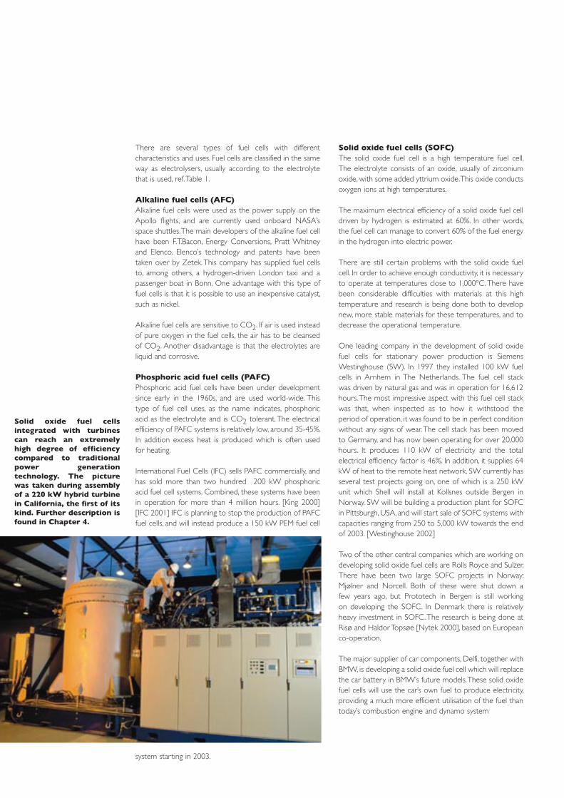
There are several types of fuel cells with different characteristics and uses. Fuel cells are classified in the same way as electrolysers, usually according to the electrolyte that is used, ref. Table 1.
Alkaline fuel cells (AFC)Alkaline fuel cells were used as the power supply on the Apollo flights, and are currently used onboard NASA’s space shuttles. The main developers of the alkaline fuel cell have been F.T.Bacon, Energy Conversions, Pratt Whitney and Elenco. Elenco’s technology and patents have been taken over by Zetek. This company has supplied fuel cells to, among others, a hydrogen-driven London taxi and a passenger boat in Bonn. One advantage with this type of fuel cells is that it is possible to use an inexpensive catalyst, such as nickel.
Alkaline fuel cells are sensitive to CO2. If air is used instead of pure oxygen in the fuel cells, the air has to be cleansed of CO2. Another disadvantage is that the electrolytes are liquid and corrosive.
Phosphoric acid fuel cells (PAFC)Phosphoric acid fuel cells have been under development since early in the 1960s, and are used world-wide. This type of fuel cell uses, as the name indicates, phosphoric acid as the electrolyte and is CO2 tolerant. The electrical efficiency of PAFC systems is relatively low, around 35-45%. In addition excess heat is produced which is often used for heating.
International Fuel Cells (IFC) sells PAFC commercially, and has sold more than two hundred 200 kW phosphoric acid fuel cell systems. Combined, these systems have been in operation for more than 4 million hours. [King 2000] [IFC 2001] IFC is planning to stop the production of PAFC fuel cells, and will instead produce a 150 kW PEM fuel cell
system starting in 2003.
Solid oxide fuel cells (SOFC)The solid oxide fuel cell is a high temperature fuel cell. The electrolyte consists of an oxide, usually of zirconium oxide, with some added yttrium oxide. This oxide conducts oxygen ions at high temperatures.
The maximum electrical efficiency of a solid oxide fuel cell driven by hydrogen is estimated at 60%. In other words, the fuel cell can manage to convert 60% of the fuel energy in the hydrogen into electric power.
There are still certain problems with the solid oxide fuel cell. In order to achieve enough conductivity, it is necessary to operate at temperatures close to 1,000ºC. There have been considerable difficulties with materials at this high temperature and research is being done both to develop new, more stable materials for these temperatures, and to decrease the operational temperature.
One leading company in the development of solid oxide fuel cells for stationary power production is Siemens Westinghouse (SW). In 1997 they installed 100 kW fuel cells in Arnhem in The Netherlands. The fuel cell stack was driven by natural gas and was in operation for 16,612 hours. The most impressive aspect with this fuel cell stack was that, when inspected as to how it withstood the period of operation, it was found to be in perfect condition without any signs of wear. The cell stack has been moved to Germany, and has now been operating for over 20,000 hours. It produces 110 kW of electricity and the total electrical efficiency factor is 46%. In addition, it supplies 64 kW of heat to the remote heat network. SW currently has several test projects going on, one of which is a 250 kW unit which Shell will install at Kollsnes outside Bergen in Norway. SW will be building a production plant for SOFC in Pittsburgh, USA, and will start sale of SOFC systems with capacities ranging from 250 to 5,000 kW towards the end of 2003. [Westinghouse 2002]
Two of the other central companies which are working on developing solid oxide fuel cells are Rolls Royce and Sulzer. There have been two large SOFC projects in Norway: Mjølner and Norcell. Both of these were shut down a few years ago, but Prototech in Bergen is still working on developing the SOFC. In Denmark there is relatively heavy investment in SOFC. The research is being done at Risø and Haldor Topsøe [Nytek 2000], based on European co-operation.
The major supplier of car components, Delfi, together with BMW, is developing a solid oxide fuel cell which will replace the car battery in BMW’s future models. These solid oxide fuel cells will use the car’s own fuel to produce electricity, providing a much more efficient utilisation of the fuel than today’s combustion engine and dynamo system
Solid oxide fuel cells integrated with turbines can reach an extremely high degree of efficiency compared to traditional power generation technology. The picture was taken during assembly of a 220 kW hybrid turbine in California, the first of its kind. Further description is found in Chapter 4.
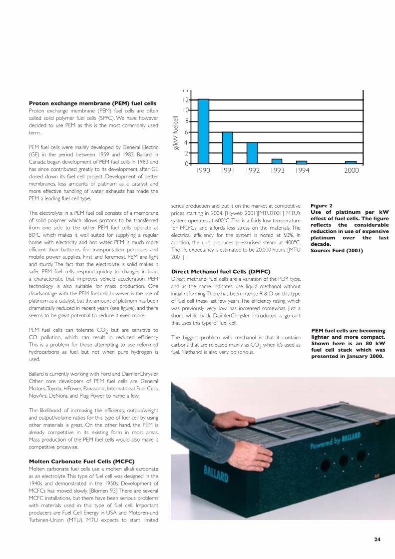
24
Proton exchange membrane (PEM) fuel cellsProton exchange membrane (PEM) fuel cells are often called solid polymer fuel cells (SPFC). We have however decided to use PEM as this is the most commonly used term.
PEM fuel cells were mainly developed by General Electric (GE) in the period between 1959 and 1982. Ballard in Canada began development of PEM fuel cells in 1983 and has since contributed greatly to its development after GE closed down its fuel cell project. Development of better membranes, less amounts of platinum as a catalyst and more effective handling of water exhausts has made the PEM a leading fuel cell type.
The electrolyte in a PEM fuel cell consists of a membrane of solid polymer which allows protons to be transferred from one side to the other. PEM fuel cells operate at 80ºC which makes it well suited for supplying a regular home with electricity and hot water. PEM is much more efficient than batteries for transportation purposes and mobile power supplies. First and foremost, PEM are light and sturdy. The fact that the electrolyte is solid makes it safer. PEM fuel cells respond quickly to changes in load, a characteristic that improves vehicle acceleration. PEM technology is also suitable for mass production. One disadvantage with the PEM fuel cell, however, is the use of platinum as a catalyst, but the amount of platinum has been dramatically reduced in recent years (see figure), and there seems to be great potential to reduce it even more.
PEM fuel cells can tolerate CO2 but are sensitive to CO pollution, which can result in reduced efficiency. This is a problem for those attempting to use reformed hydrocarbons as fuel, but not when pure hydrogen is used.
Ballard is currently working with Ford and DaimlerChrysler. Other core developers of PEM fuel cells are General Motors, Toyota, HPower, Panasonic, International Fuel Cells, NovArs, DeNora, and Plug Power to name a few.
The likelihood of increasing the efficiency, output/weight and output/volume ratios for this type of fuel cell by using other materials is great. On the other hand, the PEM is already competitive in its existing form in most areas. Mass production of the PEM fuel cells would also make it competitive pricewise.
Molten Carbonate Fuel Cells (MCFC)Molten carbonate fuel cells use a molten alkali carbonate as an electrolyte. This type of fuel cell was designed in the 1940s and demonstrated in the 1950s. Development of MCFCs has moved slowly. [Blomen 93] There are several MCFC installations, but there have been serious problems with materials used in this type of fuel cell. Important producers are Fuel Cell Energy in USA and Motoren-und Turbinen-Union (MTU). MTU expects to start limited
series production and put it on the market at competitive prices starting in 2004. [Hyweb 2001][MTU2001] MTU’s system operates at 600ºC. This is a fairly low temperature for MCFCs, and affords less stress on the materials. The electrical efficiency for the system is noted at 50%. In addition, the unit produces pressurised steam at 400ºC. The life expectancy is estimated to be 20,000 hours. [MTU 2001]
Direct Methanol fuel Cells (DMFC)Direct methanol fuel cells are a variation of the PEM type, and as the name indicates, use liquid methanol without initial reforming. There has been intense R & D on this type of fuel cell these last few years. The efficiency rating, which was previously very low, has increased somewhat. Just a short while back DaimlerChrysler introduced a go-cart that uses this type of fuel cell.
The biggest problem with methanol is that it contains carbons that are released mainly as CO2 when it’s used as fuel. Methanol is also very poisonous.
��� �� ��������
���� ���� ���� ���� ���� ����
��
����
����
����
��
��
�
�
�
�
�
PEM fuel cells are becoming lighter and more compact. Shown here is an 80 kW fuel cell stack which was presented in January 2000.
Figure 2Use of platinum per kW effect of fuel cells. The figure reflects the considerable reduction in use of expensive platinum over the last decade.Source: Ford (2001)

to Hydrogen Components, Inc. (HCI)). HCI has developed a special injection system and converts cars to hydrogen. The company has converted several cars, including a Mazda with a wankel motor, a Winnebago RV that used hydrogen as both fuel and energy source for cooking and heating, as well as a large peace of mining equipment. Some of these engines have reached efficiencies of 42%, and may be a cheaper alternative to fuel cells in the short term.
Of the larger car manufacturers, in particular BMW has been working on combustion engines using hydrogen.
Engines for stationary production of electricity and heat from natural gas can easily be converted to run on hydrogen.
TurbinesThere are currently several coal-powered gas plants that operate on coal gasification (IGCC), which uses considerable amounts of hydrogen in the fuel. The combustion chamber concept developed for syngas from coal gasification is well suited for fuel with a high content of hydrogen (syngas: synthesis gas; mixture of carbon monoxide and hydrogen). The usability of hydrogen in turbines has been verified by several turbine manufacturers, notably GE. Currently cheaper than fuel cells, turbines may be considered a transitional technology.
Norsk Hydro’s “Hydrokraft” concept was based on electric power production with turbines and hydrogen. This is elaborated on in the section on removal of CO2 in Chapter 4.
HybridsBy integrating solid oxide fuel cell technology with turbines, the electrical efficiency of a gas power plant can reach up to 80% under optimum conditions. Fuel cells alone have the potential to utilise 60% of the energy in the fuel. The rest is lost in the form of low quality heat, but also because the fuel cells are not capable of utilising all the fuel. The excess fuel in the exhaust gas can be used however with the help of gas turbines. Such a plant would still produce NOx unless pure O2 is used in the afterburner, but to a lesser degree than in a conventional power plant.
Siemens Westinghouse has started a 220 kW SOFC micro turbine “hybrid” system at the University of California in Irvine. This is the first of its kind and the efficiency is 52-53%. A 550 kW system is under development.
Regenerative fuel cellsSimply put, this is a fuel cell which produces electricity and heat, and which can reverse the process. When supplied with electricity, it can be used in electrolysis of water to produce hydrogen and oxygen. In other words the same unit is used for two functions, possibly saving on weight and costs compared to a system with separate fuel cells and electrolyser.
The efficiency rating for the one function in a regenerative fuel cell is not necessarily any less than for dedicated fuel cells or electrolysers. But the catalyst in the system cannot be optimised for both. In other words, efficiency is not at its height in both processes. Therefore, a system that will primarily produce hydrogen, for example, should be at peak performance for electrolysis. Regenerative fuel cell systems are most often based on PEM technology.
2.3.2 Burning hydrogenHydrogen can also be burned in the normal way using oxygen or air, and the heat resulting from the combustion can be used for either heating, cooking, turbines, boilers or in combustion engines.
Combustion technologyBecause of hydrogen’s high burning temperature, large
amounts of NOx will be released under standard combustion methods. It is therefore better to turn to other processes which have lower NOx emissions. Catalytic burners use a catalyst to reduce the burning temperature, thereby reducing the creation of NOx. There are several burners which use diffusion (i.e. primus stove principle) for low NOx burning of hydrogen. [Nytek, 2000]
Up to 15% H2 may be added to regular natural gas, without any need to adjust conventional burners.[Hart, 1997]
Hydrogen enginesRudolf Erren studied the use of hydrogen in combustion engines in the 1920s and developed his own method of conversion – often referred to as the Erren engine. Erren and his colleagues are supposed to have converted somewhere between 1,000 and 3,000 cars, busses and trucks to hydrogen. In the USA in the 1970s, Roger Billings converted a Model A Ford to hydrogen when he was just 16 years old. [Hart 1997] Billings based his conversions on Erren’s concepts. He and Frank Lynch later started Hydrogen Consultants (which has now changed its name
Type Area of use Electrolyte Temperature ºCAlkaline (AFC) Space travel, transportation Alkaline 50 – 200Direct methanol (DMFC) Transport, mobile equipment Polymer 80 - 200Proton-exchange-membrane (PEM) Space travel, transportation, small CHP, mobile equipment Polymer 50 – 80Phosphoric acid (PAFC) CHP, power plants Phosphoric acid 190 – 210Molten carbonate (MCFC) CHP, power plants Molten carbonate 600 – 650Solid oxide (SOFC) CHP, power plants Solid oxide 600 – 1,000
Table 1Some common fuel cell types and their uses. (CHP: Combined Heat and Power)

26
2.4 Storage of hydrogenIf hydrogen is to be used on a large scale basis, storage is a key problem. In vehicles for instance, it must be possible to store enough hydrogen to allow for the same driving distance as today’s cars. In the energy sector the ability to store the hydrogen effectively, quickly and inexpensively is most important. This chapter will take a look at hydrogen storage with special focus on storage in vehicles.
Hydrogen is a substance with high energy content compared to its weight. This is the reason that hydrogen is naturally the first choice in space travel and very well suited for air travel. On the other hand, the energy content compared to volume is rather low. This poses greater challenges with respect to storage compared to storage of gasoline which is a liquid.
The US DOE has determined that an energy density of 6.5 weight percent hydrogen and 62 kg hydrogen per m3 must be achieved, in order for a hydrogen storage system of appropriate weight and size to facilitate a fuel cell vehicle driving distance of 560 kilometres.
There are basically three options:-hydrogen may be compressed and stored in a pressure tank -hydrogen may be cooled to a liquid state and kept cold in a properly insulated tank-hydrogen may be stored in a solid compound
Various strategies for storage are described in the following section.
Compressed hydrogenStoring hydrogen under pressure has been done successfully for many years.
The three main types of tanks are:-Steel-Aluminium core encased with fibreglass (composite)-Plastic core encased with fibreglass (composite)
In stationary systems where weight and size are not decisive factors, steel tanks are a good solution, but for vehicles, traditional pressure tanks are problematic regarding both weight and volume. There has been considerable breakthrough the last few years in the development of a new type of composite tank which can store hydrogen at 350 bar pressure and at the same time meet the current safety standards. This type of tank has a storage capacity of 10-12 weight percent hydrogen [DOE, 2000], whereby the weight of the tank no longer is a problem. Progress is also being made on tanks which can store hydrogen at 700 bar pressure. This will reduce the tank volume, which is necessary to achieve the desirable driving distance. Light weight composite tanks which utilise space better than the usual cylindrical tanks have also been designed.
Special H2 compressors are normally used to pressurise the hydrogen. If pressure electrolysers are used to supply compressed hydrogen, the process of compressing could be reduced or eliminated all together depending on what pressure level is needed. This would be a more efficient system, and a simpler and less expensive solution.
Liquid hydrogenHydrogen can be stored as a liquid (LH2) at 20 K (-253º C) in super insulated tanks. LH2 is particularly interesting for long distance transportation purposes and as fuel in spacecraft and airplanes. A great deal of experience has been accumulated over the years when it comes to the usage and handling of LH2. In order to cool the hydrogen down, energy equalling 30-40% of that in the fuel is needed. Development of a new cooling process that would cut the energy use in half is considered feasible. [Nytek 2000] LH2 is especially well suited for use in air and space travel, where its characteristics rate it higher than any other fuel. Today, LH2 is the most frequently used fuel within space travel.
BMW has studied use of liquid hydrogen in combustion engines in cars for over 20 years and says that using liquid hydrogen in automobiles is a good alternative. The German company Linde has developed a tank for liquid hydrogen where the cold from some of the liquid hydrogen is used to cool down the insulation surrounding the tank; this is done with cooling elements. This way the tank keeps the hydrogen in a liquid state for up to 12 days.[Hyweb, 2000] This type of tank is now being tested and will probably be installed in BMW’s hydrogen cars among others.
Metal hydrideCertain metals and metal alloys have the ability to absorb hydrogen under moderate pressure and temperature, creating hydrides. Hydride is a compound which contains hydrogen and one or more other elements. A metal hydride tank contains, in addition to a heat manipulation system, granular metal which absorbs the hydrogen like a sponge absorbs water. The heat system draws heat away when hydrogen is filled into the tank, and applies heat when the hydrogen is taken out of the tank.
The hydrogen is released from the metal hydride when heat is applied. This heat may, for example, be excess heat from the fuel cells.
A metal hydride tank is considered to be a very safe fuel system in the event of a collision because the loss of pressure in a punctured tank will cool down the metal hydride, which will then cease to release hydrogen.
Several metal hydrides are available commercially, representing a good solution for hydrogen storage where the weight factor is not a problem. For vehicles, the problem with metal hydride is the high weight compared
NASA has been a heavy user of hydrogen in space programs for several decades. This shows a storage tank for liquid hydrogen and hydrogen tank trucks. (photo: NASA)

to the amount of hydrogen stored. The problem of weight has still not been solved in spite of extensive research. Researchers are therefore trying to think in new directions, by trying to lighten the alloys for one, and finding methods of packing the hydrogen in higher concentrations.
At the Institute for Energy Technology at Kjeller in Norway (IFE), work is being done on storing hydrogen in alloys with extremely densely packed hydrogen atoms, which allows for higher concentrations.
Work is being done on finding cheaper metal alloys which have the ability to absorb large amounts of hydrogen, and at the same time release the hydrogen at a relatively low temperature. The International Energy Agency’s (IEA) metal hydride program has a goal of 5 weight percent absorbed hydrogen and hydrogen release at < 100ºC.
NaAlH4 is a promising, reasonably inexpensive metal hydride. With its 4 weight percent hydrogen and 150 ºC release temperature NaAlH4 almost meets the IEA requirements. This metal hydride is now the focus point for development of a hydrogen storage system in the USA, and is also being studied at IFE.
Today’s modern PEM fuel cells operate at low temperatures. If the excess heat from the fuel cells is to be used to release hydrogen, it is important that the hydride releases the hydrogen at the same temperature. The energy efficiency of the system will be lower, and the system more complex, if extra heat must be generated to remove the hydrogen from the tank.
Metal hydride can also be used for compressing hydrogen.
Hydrogen in carbonsCertain carbons have a very large surface area and research has been going on for several years to try to store hydrogen in these materials. According to several
research groups, carbon nanostructures such as nanofibers, nanotubes and fullerenes have shown promising abilities to absorb hydrogen.
Intense efforts are being made to develop methods for producing single-walled nanotubes economically on a large scale. Use of laser technology has made it possible to produce a high percentage of nanotubes with the exact diameter and level of purity needed. Production of nanotubes is growing rapidly. Nanotubes have several interesting qualities which to good effect can be used in hydrogen technology. For example, they can be used in fuel cells, ultra condensers for efficient storage of retardation energy and hydrogen storage. An American research group has repeatedly achieved storage of 7.5 weight percent hydrogen in single-walled nanotubes at room temperature. In these experiments the nanotubes had been subjected to ultrasound. Sources say it will be possible to reach a somewhat higher storage capacity in the not too distant future. Presently, work is done to scale up these experiments. [Dillon, 1999]
It would be appropriate here to mention that there is a great deal of disagreement surrounding the storage capacity of carbons. For instance, a German research team has done very thorough attempts at repeating the above mentioned American experiment, and still only achieved a very low storage capacity for hydrogen. [Haluska 2001]
MethanolMethanol (CH3OH) has a high content of hydrogen which can relatively easily be extracted by reforming. There are those that say methanol would be a good transitional fuel solution for smaller cars. The advantage of methanol is that it is liquid under normal air pressure and room temperature, and has a high content of hydrogen compared to other fossil fuels. Methanol is produced from natural gas by steam reforming the natural gas into synthesis gas. In a methanol car with a reformer, the methanol will be reformed into hydrogen which is then used in the fuel cell. The energy loss in these two processes is high and the system efficiency therefore low.
Methanol (wood spirit) is a very poisonous liquid with many similarities to ethanol. Methanol has been found to be cancer-causing, corrosive and could pollute the ground water. Several large oil companies have very clearly given the signal that they will not develop a methanol infrastructure because the safety risks are too great.
Several environmental organisations, including Bellona, will actively oppose building such an infrastructure. In addition to the directly damaging effects of methanol, a temporary methanol infrastructure would also delay development of the hydrogen infrastructure. It would require heavy investment, while the methanol-fuelled cars would remain on the road for several decades. Another drawback with a
������
������ ����
��������������Figure 9Hydrogen gas moves in toward the interface. There the hydrogen molecule is split into hydrogen atoms which are absorbed by the metal, whereby hydrogen is stored in the metallic matrix.
�
�
��
���������������
����������
���� �������������� ���� �������
�
�
�
�
�
�
�
�
� �����
�������� ���� ���
�������� ������ ���
�������� ���� ���
�������� ������ ���
�������� ���
���� ������� ���� ����
����� ����� ����� ����� �����
��� ������� ���� ����
Figure 10Hydrogen, gasoline and methanol compared as to complexity of the fuel system and infrastructural costs. (source: Sandy Thomas)

28
methanol infrastructure is the fact that fuel cell cars which cannot use methanol directly, must be equipped with an expensive reformer. It would most likely take several decades before direct methanol fuel cells (DMFC) could be used in regular vehicles. Costs are therefore placed on the consumer, while making fuel cell technology more expensive than necessary.
It has often been stated that methanol can be transported and handled just like gasoline, but this is not true. Methanol is very corrosive, and a methanol spill could cause severe damage to the environment. Methanol mixes with water and is almost impossible to reclaim once spilled.
A fuel cell car with a methanol reformer will have high levels of CO2 emissions – probably somewhere between 60% and 70% of a comparable gasoline car with combustion engine.[NOU 1998:11] There would also be hydrocarbon and CO emissions. Increased distribution of methanol will pose substantial risk of poisoning both humans and animals. Because of the low system efficiency and high emissions compared to hydrogen and electricity, methanol will not measure up to the future fuel requirements for vehicles. Methanol therefore cannot be recommended as a fuel.
Gasoline and other hydrocarbonsConverting gasoline (alternatively a special blend, a form of naphtha) into hydrogen-rich gas in cars has also been the subject of much research and development. Oil companies, having invested enormous amounts of money into a gasoline infrastructure, are especially interested in this option. These temporary solutions offer, as with methanol, less performance and fuel efficiency than solutions based on pure hydrogen. This would also require a very complex reformer which makes it expensive, heavy and unsuitable. It is also very difficult to remove hydrocarbons and CO, and CO destroys the catalyst in PEM fuel cells. This type of reformer would have to operate at such high temperatures that it would also create NOx. Just as with methanol, only to a greater degree, the increased costs are placed on the car owner. The system becomes more complex, making the car more susceptible to technical problems, while efficiency is reduced; in other words, not a very wise choice. Hybrid cars which are already on the market offers the same lower levels of CO2 as would fuel cell cars with gasoline and methanol as fuel. SAAB’s combustion engine with variable compression (not yet in production), is supposed to have equally low levels of CO2. [Automotive World, 2000]
Stationary storageHydrogen can be stored in pressure tanks, in underground cavities and as a liquid in superinsulated tanks. All this is standard technology. For storage of very large amounts of hydrogen, the most economical method is underground storage under pressure.[NRF 2001]
The expenses of storing hydrogen in caverns will vary
according to the geological formations, but this could be an inexpensive option. The German town of Kiel is supposed to have stored city gas with a hydrogen content of 60-65% in a gas storage hall with a volume of 32,000 m3 under 80-100 bar pressure since 1971.[Winter, 1988] Usable as such underground storage areas may be empty reservoirs, aquifers, caverns or empty cavities in salt formations.
2.5 Transport of hydrogenPipelinesIn the USA there is 720 km of hydrogen pipeline network and in Europe about 1,500 km. Over great distances, pipeline transport of hydrogen could be an effective way of transporting energy. The energy loss in an electric power grid can be up to 7.5-8% of the energy it is transferring. This is about double of what is needed to feed gas through a pipeline of the same length.
Hydrogen pipes that are in use today are constructed of regular pipe steel, and operate under pressure at 10-20 bar, with a diameter of 25-30 cm. The oldest existing system is found in the Ruhr area. It is 210 km long and distributes hydrogen between 18 producers and consumers. This network has been in use for 50 years without any accidents. The longest hydrogen pipeline is 400 km and runs between France and Belgium.
With little or no changes, the majority of existing steel natural gas lines can be used to transport mixtures of natural gas and hydrogen. It is also possible, with certain modifications, to use pure hydrogen in certain existing natural gas lines. This depends on the carbon levels in the pipe metal. Newer gas pipelines such as those in the North Sea, have low carbon content and are therefore suitable for transporting hydrogen. If the speed is increased
Figure 11Costs of hydrogen compared to gasoline with and without EU taxes.
Table 2Summary of weight and volume of different tank types. All examples have the same driving distance when using the same type of vehicle.Source: Ford, 2001 and Quantum, 2001
Vehicles with equal driving distances per fill-up Mass (kg) Volum (L)Gasoline/combustion engine 50 70Compressed hydrogen (350 bar) / fuel cells 90 320Compressed hydrogen (700 bar) / fuel cells ~100 180Liquid hydrogen / fuel cells 45 190Hydrogen in metal hydride / fuel cells 200-600 180
Pri
ce p
r. N
m3 i
n E
UR

by a factor of 2.8 to compensate for hydrogen having 2.8 times lower energy density per volume than natural gas, the same amount of energy can be moved. The fact is that by using efficient hydrogen technology such as fuel cells, etc., the same amount of transported energy will yield increased output at final consumption.
In the natural gas distribution network, pressure is low, around 4 bar, and so cheaper plastic pipe is usually used. PVC (Poly Vinyl Chloride) and the newer HDPE (High Density Poly Ethylene) are too porous and not usable for transporting hydrogen. [Princeton, 1997]
Gas pipelines, in addition to being used for transportation, can also be used to store great quantities of hydrogen. By regulating the pressure in the pipes, it is possible to use the large volume a pipeline offers as storage during peak situations.[Winter, 1988]
Natural gas which is transported from the Norwegian shelf to the Continent in pipelines can hold an additional 15% hydrogen. This hydrogen can be produced in Norway with CO2 depositing. The gas which is transported can consequently be sold at a higher price, while carbon taxes in the receiving country must be comparably reduced. In
this way, the income from the hydrogen will contribute more added value to the Norwegian society. The mixture hydrogen/methane can be used in the same way as natural gas, and will produce a higher combustibility factor because of the higher energy content.
Transport of liquid hydrogenLiquid hydrogen (LH2) is hydrogen which has been cooled below -253ºC. The cooling process requires a great deal of energy, but for long-distance transportation and as fuel in certain applications used in air and space travel, LH2 still has obvious advantages over other fuels.
Roadway transportationHydrogen can be shipped with tank trucks in both liquid and compressed states. Several companies currently deliver these types of tank trucks.
Ocean transportationHydrogen can be transported as a liquid in tank ships. These are not too different from LNG tankers, aside from the fact that better insulation is required to keep the hydrogen cooled down over long distances. The Japanese WE-NET and the German-Canadian Euro Quebec have reported on the use of such tanks. The evaporated hydrogen may be used as fuel onboard.
Hydrogen is the most widely found base element in the universe. This photo was taken by the Hubble telescope.

30
In 1990, the German institute for materials research declared that LH2 could be given the same safety rating as LPG and LNG, and transport of LH2 into German harbours was approved.
Air transportationThere are several advantages in transporting LH2 by air rather than by ship. LH2 is lightweight and the delivery time is much shorter, and evaporation is therefore not a big problem. Studies on this have been done by CDS Research Ltd. in Canada, with support from the WE-NET program.

In developing countries, air pollution is an even greater problem. A survey done by The World Bank shows that more than 40,000 people die each year as a result of air pollution in India’s urban areas. [The Cost of Inaction: Valuing the economy wide cost of degradation in India, World Bank, Asia Division, 1995]
Emissions can be reduced in two ways (both are necessary): behavioural changes that reduces the transportation load, and technological development that reduces the emissions per driven kilometre. Only the latter is discussed in this report.
There is great potential for reducing emissions by further developing existing technology, but this will only allow for marginal improvements in CO2 levels. These improvements would probably just disappear in the mire of expected increase in traffic anyway. Based on this, there is a need for a new engine and fuel technology. Electricity and hydrogen are currently the only solutions which allow for zero emissions for all components in exhaust fumes.
Fuel cells have the potential to solve many of the problems related to emissions of exhaust. With hydrogen as a fuel, the vehicles will have zero emissions and high efficiency, with driving distances comparable to today’s conventional vehicles. These are the three main requirements to be met by a sustainable solution with regard to the environment, profits, and the consumer.
The Transportation SectorThe transportation sector accounts for 31% of the total energy usage in the EU. 98% of the sector uses petroleum-based fuel. Traffic on the roadways is the greatest source of noise and local air pollution, and a considerable contributor to global emissions of greenhouse gases.
In 1999 32% of CO2 emissions in Norway were caused by transportation, whereof road transport was the source for 65%. In the period between 1990 and 1999, greenhouse gas emissions from this sector increased by 26%. [National Transportation Plan, 1999] According to the Norwegian Pollution Authority (SFT), 750,000 people in Norway suffer from noise and/or pollution from traffic. Traffic on the roadways is currently the greatest source of detrimental environmental impact in Norway.[SFT, 30 June 1998]
The World Health Organisation’s international cancer institute in Lyon, France, has concluded that emissions from diesel cars are very probably cancer-causing. There is no similar accurate documentation for gasoline exhaust. Particles in diesel exhaust damage the DNA molecule, and this damage leads to the development of cancer. On an annual basis, 250 to 300 people in Norway die of cancer as a result of particle emissions from diesel vehicles.[Professor Tore Sanner of the Department for Environmental and Work-related Cancer at the Radium Hospital, to Aftenposten February 22. 1999]
Figure 12Only hydrogen and fuel cells meet all emissions standards for environmentally friendly vehicles.
Figur 13
���
�������������� ��� ���������
����
�����
���
�
���
���
��
�
���
���
���
�
���� ��������
��
���
��
��
���
���
��
��
���
���
�����
��
���
��
���
���
���
��
��
��
��
��
���
���
��
�
���
���
�
��
���
�
���
���
In 1992 The World Health Organisation ranked Beijing as the world’s second most polluted metropolis. Since then, the number of motor-driven vehicles has doubled. The number of cars increases by 13% annually. This makes it increasingly difficult and more dangerous to bicycle in China, both with regard to pollution and traffic safety.
33High
fuel efficiency
Long range
Zero-emission
Electrisity
Fuelcellwith hydrogen
GazolineNatural gasMethanol
Diesel

32
There seems to be widespread agreement that hydrogen is the fuel of the future for the transportation sector. [Ogden et al., 1999] However, certain companies (incl. Statoil, Metanex, DaimlerChrysler) has suggested that methanol could be used in the changeover phase, and argue that methanol is compatible with the existing infrastructure. Others say that hybrid and electric cars could be the intermediate solution. Some, such as General Motors and ExxonMobil, maintain that we should continue to improve the existing combustion engines until we can phase in the hydrogen solution at the right time. [Weiss et al., 2001] Part of this reasoning, as well as the rhetoric behind it, can best be understood by looking at the foundation of their technological development and where they have made their heaviest investments.
The majority of the oil companies (such as Shell, Norsk Hydro and Texaco) do not wish to develop a new infrastructure twice – with the huge costs this involves – and refuse therefore to consider using methanol in an in-between phase. To back up this argument they say that even though a hydrocarbon-based infrastructure might be cheaper, it is more than offset by the fact that the required onboard reforming process would make vehicles more complex and reduce the efficiency. The problem here shows how important it is that transportation is seen in connection with energy supplies and lifecycle analyses from beginning to end. This means that producing the energy carrier must first be taken into account, then add the total cost of the infrastructure as well as the cost of producing and using the associated vehicles, while at the same time taking into consideration the environmental costs of the emissions throughout the entire process. Looking at it from this point of view, Bellona agrees with Shell Hydrogen: “Do it once and do it right”. [Shell 2000]
The transportation sector is being hit by ever increasing regulation and taxes. It is especially the zero emissions vehicle demands from California (ZEV), and the EU’s Auto-oil Program, which are forcing the development in a more environmentally friendly direction.
The auto industry has been very unwilling to improve their environmental footprint, but are now being pushed towards technological improvements. This is also the case to an increasing degree in developing countries which have previously been used as a dumping ground for the auto industry. In California, the “Zero Emission Vehicle”, or “ZEV Program” was adopted as early as 1990 (see Internet address: http://www.arb.ca.gov/msprog/zevprog/zevprog.htm).
Originally, this meant that 10% of all new cars sold should comply with the zero emissions definition by 2003. The regulation was confirmed by a popular vote in May 2000. In January 2001, The California Air Resources Board (CARB), under heavy pressure from the industry, decided to uphold the ZEV Program, but allowed for a more gradual phase-in which includes credits for partial zero emissions vehicles (PZEV). The status today is that at least 4% of all vehicles sold in 2003 must be ZEV, while 6% can be PZEV, which earns ZEV-credits. This means that the auto manufacturers will get low emissions vehicles partially approved, but the plan is to increase the restrictions to 16% ZEV vehicles by 2018. At the same time, the manufacturers will receive special credits for putting zero emission electric and hydrogen cars out on the market at an earlier stage. Massachusetts, Maine, New York and New Hampshire have also adopted ZEV programs similar to California’s.
This chapter describes some of the newest prototype cars which have been presented by the larger car manufacturers. Emphasis has been placed on describing
Table 3This shows emissions and consumption for different fuels in cars. All figures relate to gasoline today. The figures for combustion and production emissions of CO2 relate to CO2 emissions from burning gasoline. “2020 Minus” depicts a scenario where exhaust standards are not raised beyond current levels and all extraneous factors are constant. “2020 Plus” depicts a scenario where the potential for technological improvements are implemented to their fullest.(Source for figures is TI (1998a), but Bellona has created the comparative table).
Otto engine: -Petrol -Methanol (combustion) -LPG -CNG -Hydrogen (combustion)Diesel engine: -Diesel -DME -RME (biodiesel)Electric engine -Batteries -Hydrogen (fuel cell) Methanol (fuel cell) -Hybrid
1,001,130,901,00-
0,740,680,74
0,31
0,52
0,610,680,550,90-
0,450,390,45
0,250,310,740,30
0,320,350,280,74-
0,320,290,35
0,250,310,740,25
1998 2020 minus
2020 plus
Energy consumption
1,001,180,820,820
0,770,640
0
0,50
0,590,730,500,730
0,450,360
000,770,32
0,320,360,270,590
0,320,270
000,770,27
1998 2020 minus
2020 plus
CO2 discharges from combustion
1.231.680.910.910.00
0.860.730.64
00.000.000.64
0.731.000.550.820.00
0.500.450.36
00.011.090.36
0.360.500.270.680.00
0.360.320.23
00.011.050.32
1998 2020 minus
2020 plus
CO2 discharges: combustion/production
Figure 14Energy consumption with different fuels per driven meter, including production. Gasoline, diesel and natural gas used in combustion engines, hydrogen and methanol used in fuel cells. Hydrogen locally produced by steam reforming of natural gas. Notice that there is steady improvement with all types of vehicles.(Source: Bauen & Hart 1999)
���������������
��������������� ���
�������� ��������
�������� ��
������ ����������� ����� ���� �� ������
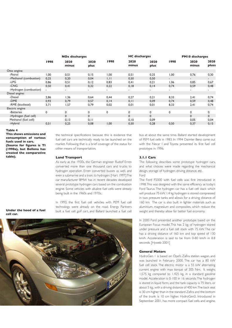
the technical specifications because this is evidence that fuel cell cars are technically ready to be launched on the market. Following that is a brief coverage of the status for other means of transportation.
Land TransportAs early as the 1930s, the German engineer Rudolf Erren converted more than one thousand cars and trucks to hydrogen operation. Erren converted busses as well, and even a submarine and a train, to hydrogen. [Hart 1997] The car manufacturer BMW has in recent decades developed several prototype hydrogen cars based on the combustion engine. Some vehicles with alkaline fuel cells were already being built in the 1960s and 1970s.
In 1993, the first fuel cell vehicles with PEM fuel cell technology were already on the road. Energy Partners built a fuel cell golf cart, and Ballard launched a fuel cell
bus at about the same time. Ballard started development of PEM fuel cells in 1983. In 1994 Daimler Benz came out with the Necar I and Toyota presented its first fuel cell prototype in 1996.
3.1.1 CarsThe following describes some prototype hydrogen cars, and what choices were made regarding the mechanical design, storage of hydrogen, driving distance, etc.FordThe Ford P2000 with fuel cells was first introduced in 1998. This was designed with the same efficiency as today’s Ford Taurus. The hydrogen car has a fuel cell stack which will produce 75 kW. 1.4 kg hydrogen is stored compressed in two pressure tanks and allows for a driving distance of 160 km. The car is also built in lighter materials such as aluminium, magnesium and composites, which reduce the weight and thereby allow for better fuel economy.
In 2000 Ford presented another prototype based on the European Focus model. This has 2 kg. of hydrogen stored under pressure and a fuel cell stack with 75 kW. The car has a driving distance of 160 km and top speed of 130 km/h. Acceleration is said to be from 0-80 km/h in 8.8 seconds. [Hyweb 2001]
General MotorsHydroGen 1 is based on Opel’s Zafira station wagon, and was launched in February 2000. The car has a 80 kW fuel cell stack. The electric motor is a 55 kW alternating current engine with max torque of 305 Nm. It weighs 1,575 kg compared to 1,425 kg. in a standard gasoline model. Acceleration is 0-100 in 16 seconds. The hydrogen is stored in liquid form, and the tank capacity is 75 liters, or about 5 kg., with a driving distance of 400 km. The back seat is 30 cm higher than in the standard Zafira and the bottom of the trunk is 10 cm higher. HydroGen3, introduced in September 2001, has more compact fuel cells and engine,
Under the hood of a fuel cell car.
Otto engine: -Petrol -Methanol (combustion) -LPG -CNG -Hydrogen (combustion)Diesel engine: -Diesel -DME -RME (biodiesel)Electric engine -Batteries -Hydrogen (fuel cell) Methanol (fuel cell) -Hybrid
1,000,250,860,50-
2,860,933,71
0
0,51
0,510,200,510,41-
1,360,791,57
000,130,25
0,150,040,120,32-
0,640,570,79
000,110,08
1998 2020 minus
2020 plus
NOx discharges
1,001,110,830,22-
0,440,140,02
0
1,00
0,510,500,410,18-
0,270,110,01
000,100,50
0,250,500,210,14-
0,210,090,01
000,090,28
1998 2020 minus
2020 plus
HC discharges
1,00-1,060,74-
8,330,748,33
0
0,50
0,76-0,850,59-
2,410,592,41
000,050,37
0,30-0,670,48-
0,740,480,74
000,040,15
1998 2020 minus
2020 pluss
PM10 discharges
Table 4This shows emissions and consumption of various fuels used in cars.(Source for figures is TI (1998a), but Bellona has created the comparative table).

34
so that space is the same as a normal Zafira. Opel has made several successful cold start tests on the system, and has started the stack cooled-down to a temperature of -20º C. The goal is to be able to start the system at -40º C. Opel’s Zafira HydroGen1 is now undergoing a thorough testing program and put through heavy stresses under different conditions. GM has entered into an agreement with Toyota to develop a fuel cell vehicle.
GM says its most important challenge in the near future is to establish a fuel infrastructure, reduce the costs, and develop lighter and more compact storage methods for the fuel of the future. According to GM, “clearly [the fuel of the future] is hydrogen, because an engine that uses hydrogen fuel cells has optimal efficiency and only emits water, is practically soundless and at the same time offer a high degree of driving pleasure”. [Opel, 2000]
DaimlerChryslerIn 1994, Daimler Benz demonstrated Necar 1, a mobile fuel cell laboratory in a truck. Necar 2, introduced in 1996, is a six-seated mini van where hydrogen is stored pressurised, just as in Necar 1. Necar 3 came in 1997 and was a two-seater A-class Mercedes run on methanol. In March 1999, the hydrogen-based Necar 4 was introduced, and Necar 5, with a methanol reformer, was shown for the first time in 2000. Aside from the type of fuel, there is very little that distinguish Necar 5 from Necar 4. Methanol is a fuel Bellona considers to be unacceptable because of the high levels of CO2 emitted. The following section describes the Necar 4 more closely.
Necar 4 is a Mercedes A Class where the entire fuel cell system of 70 kW is placed inside the sandwich bottom of the car. This bottom was originally constructed for electric car batteries. The car has 5 seats, good driving performance and the same trunk volume as an ordinary A-Class. The fuel tank with liquid hydrogen is placed under the trunk. The tank can store 5 kg. hydrogen and has a driving distance of 450 km between fill-ups. The electric motor produces 55 kW, and the top speed is 145 km/h. Acceleration is 0 – 50 km/h in 6 seconds, compared to 4 seconds for the gasoline (60 kW) and 6 seconds for the diesel models (44 kW). Acceleration from 0 – 100 km/h is 26.3 seconds, compared to 12.9 for gasoline and 18 for diesel cars. It weighs about 300 kg more than a gasoline car, but DaimlerChrysler is confident that the weight will be reduced considerably. The car was test-driven more than 10,000 km in 380 hours. The average fuel usage was 1.1 kg hydrogen/100 km., which equals 4.0 litre gasoline/100 km. In comparison (under the same tests), a standard A class uses 7.1 litre gasoline/100 km. On a whole, 37.7% of the energy in hydrogen is used to propel the car (tank to
wheel efficiency). Comparable numbers for A-Class with gasoline is 16–18%, and 22-24% for the diesel model. The fuel cells have an electric efficiency factor of 62.2%.
DaimlerChrysler states that the greatest advantages of the fuel cell are:-Energy efficiency-Zero emissions when operated on hydrogen-Low noise levels-Greater comfort
DaimlerChrysler has also stated that of all the alternatives, fuel cells are the most promising, and is investing some USD 1.35 billion on further development until the first vehicles are on the market. DaimlerChrysler will start limited sale of fuel cell cars in 2004. (Friedmeier 2000] Fuel cell cars will cost the same as the diesel model of the A-Class [Calstart 1999] and the first cars will use hydrogen as fuel, most likely compressed in pressure tanks.
BMWThe BMW 750 hl is modelled after BMW’s 7-Series. It has a V12 combustion engine using liquid hydrogen as primary fuel, but switches automatically over to gasoline when the hydrogen tank is empty.
The super insulated hydrogen tank has enough fuel to drive 350 km. The gasoline tank is the standard type from the 7 Series, allowing an extra 500 km driving distance. Hydrogen is filled automatically by a robot at the hydrogen station while the driver waits in the car. Such robot serviced hydrogen stations are now being built in Germany. One is already open in Munich and several more are planned for Germany and Italy.[Hyweb 2001]
The car is presently produced in a limited number (15) only, but will be on sale with BMW’s next 7 series.[BMW 2000]
Several hydrogen vehicles are now undergoing testing around the world. This fuel cell van is being tested by a firm in Hamburg. Other important demo projects are being done in München, California and Tokyo.

BMW also presented a version based on the compact car Mini in 2001. The price is about 5% higher than the standard gasoline model. NOx is created under high temperatures in the cylinders of a combustion engine, but with a lean hydrogen mix this can be reduced.
There are no existing statistics on NOx emissions from this model compared to the one run on gasoline. The efficiency of a combustion engine is, as previously mentioned, lower than in fuel cells, and this also applies to a combustion engine which runs on hydrogen.
ToyotaToyota was the first to mass-produce hybrid cars, and has sold several tens of thousands of the Prius model. When the company invests heavily in the development of fuel cells, and repeatedly confirms that it will start sale of fuel cell cars in 2003, there is all reason to believe in its success.
Toyota used metal hydride as storage substance in its first hydrogen cars. In the prototype FCHV-4 based on the Kluger V model, compressed hydrogen is used (250 bar). Toyota has plans for a limited series (30-50 vehicles) of FCHV-4 in 2003. Compared to the other fuel cell prototypes described above, Toyota uses a hybrid design with about the same power system as the Prius. In short, they replaced the combustion engine with a fuel cell stack, and substituted a hydrogen storage unit for the gasoline tank. This hybrid design will also require a certain number of batteries. With a hybrid design it is very simple to save the energy from braking and reduce the need for a large fuel cell stack.
The hydrogen is stored in pressurised tanks, and the driving distance is estimated at 250 km. The fuel cell stack which Toyota has developed yields 90 kW. The electric motor has a permanent magnet, a maximal effect of 80 kW, and torque of 260 Nm.; top speed is 150 km/h. Toyota has tested the fuel cell car against a gasoline driven Kluger V, and reports a tank to wheel efficiency of 16% for the gasoline car as opposed to 48% for the hydrogen car [Toyota, 2001]. In June 2001 they started road tests on a small fleet of hydrogen cars in Japan.
3.1.2 BusesUse of hydrogen in buses is already well along and found to be quite satisfactory. The majority of the hydrogen buses that have been demonstrated use compressed hydrogen stored in cylinders on the roof. The fuel cell system fits into the regular engine space or on top of the roof. Buses, unlike smaller cars, are built to order, leaving the manufacturing operations easier to customise. In addition, busses usually fuel up at a limited number of depots, so building up an infrastructure is relatively simple.
A fuel cell bus from DaimlerChrysler was used for demonstration purposes for a two-week period in Oslo in the Fall of 1999. The bus was put in a regular route and the reaction by the general public to the fact that the bus was run on hydrogen was very positive.[Hydro, 2000] Ballard and the Canadian bus company TransLink have recently concluded a very successful test project with three fuel cell buses which covered more than 67,000 km. and carried over 110,000 passengers. In Germany, MAN has used hydrogen buses in regular routes with much success. The passengers there were overwhelmingly positive to using hydrogen as fuel.
In Brazil, India, China, Egypt and Mexico, 40-50 fuel cell buses will be tested out in the next few years, in co-operation with the UN. These five countries will put the buses into service in their more polluted cities such as Sao Paulo, Mexico City, Cairo, New Delhi, Beijing and Shanghai. A similar project is under way in Europe. 30 buses from DaimlerChrysler will be put into service in ten cities in 2002-2003. In Oslo plans are also under way to start using hydrogen buses and the major bus company hopes to have 125 pollution-free buses in service by 2010. Fuel cell buses is expected to be commercially available by 2004. [Friedmeier, 2000]
The European bus manufacturers which are developing hydrogen buses are Mercedes, MAN, Neoplan, Scania and Volvo.
3.1.3 MotorcyclesThe world’s fleet of two-wheel motorised vehicles numbers just over 200 million units, and is expected to exceed 500 million by 2010. The Asia/Pacific Ocean region
Toyota’s FCHV-4 is based on the Kluger V/Highlander model (a so-called “Sports Utility Vehicle” - SUV). It has 5 seats.
��������
��������
Figure 15Tank-to-wheel efficiency for the Kluger V with g a s o l i n e / c o m b u s t i o n engine and hydrogen/fuel cells.
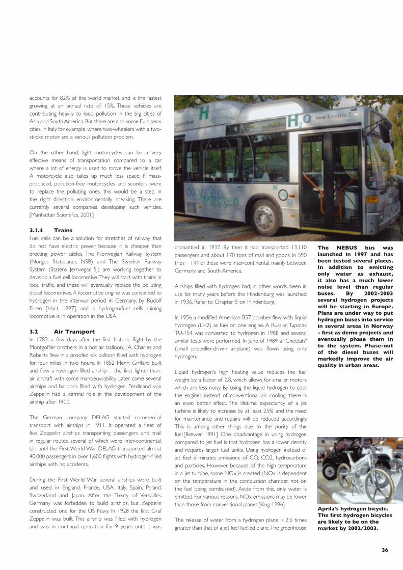
36
accounts for 82% of the world market, and is the fastest growing at an annual rate of 15%. These vehicles are contributing heavily to local pollution in the big cities of Asia and South America. But there are also some European cities, in Italy for example, where two-wheelers with a two-stroke motor are a serious pollution problem.
On the other hand, light motorcycles can be a very effective means of transportation compared to a car where a lot of energy is used to move the vehicle itself. A motorcycle also takes up much less space. If mass-produced, pollution-free motorcycles and scooters were to replace the polluting ones, this would be a step in the right direction environmentally speaking. There are currently several companies developing such vehicles. [Manhattan Scientifics, 2001]
3.1.4 TrainsFuel cells can be a solution for stretches of railway that do not have electric power because it is cheaper than erecting power cables. The Norwegian Railway System (Norges Statsbaner, NSB) and The Swedish Railway System (Statens Jernvegar, SJ) are working together to develop a fuel cell locomotive. They will start with trains in local traffic, and these will eventually replace the polluting diesel locomotives. A locomotive engine was converted to hydrogen in the interwar period in Germany, by Rudolf Erren [Hart, 1997], and a hydrogen/fuel cells mining locomotive is in operation in the USA.
3.2 Air TransportIn 1783, a few days after the first historic flight by the Montgolfier brothers in a hot air balloon, J.A. Charles and Roberts flew in a proofed silk balloon filled with hydrogen for four miles in two hours. In 1852 Henri Griffard built and flew a hydrogen-filled airship – the first lighter-than-air aircraft with some manoeuvrability. Later came several airships and balloons filled with hydrogen. Ferdinand von Zeppelin had a central role in the development of the airship after 1900.
The German company DELAG started commercial transport with airships in 1911. It operated a fleet of five Zeppelin airships transporting passengers and mail in regular routes, several of which were inter-continental. Up until the First World War DELAG transported almost 40,000 passengers in over 1,600 flights with hydrogen-filled airships with no accidents.
During the First World War several airships were built and used in England, France, USA, Italy, Spain, Poland, Switzerland and Japan. After the Treaty of Versailles, Germany was forbidden to build airships, but Zeppelin constructed one for the US Navy. In 1928 the first Graf Zeppelin was built. This airship was filled with hydrogen and was in continual operation for 9 years until it was
dismantled in 1937. By then it had transported 13,110 passengers and about 170 tons of mail and goods, in 590 trips – 144 of these were inter-continental, mainly between Germany and South America.
Airships filled with hydrogen had, in other words, been in use for many years before the Hindenburg was launched in 1936. Refer to Chapter 5 on Hindenburg.
In 1956 a modified American B57 bomber flew with liquid hydrogen (LH2) as fuel on one engine. A Russian Tupolev TU-154 was converted to hydrogen in 1988 and several similar tests were performed. In June of 1989 a “Cheetah” (small propeller-driven airplane) was flown using only hydrogen.
Liquid hydrogen’s high heating value reduces the fuel weight by a factor of 2.8, which allows for smaller motors which are less noisy. By using the liquid hydrogen to cool the engines instead of conventional air cooling, there is an even better effect. The lifetime expectancy of a jet turbine is likely to increase by at least 25%, and the need for maintenance and repairs will be reduced accordingly. This is among other things due to the purity of the fuel.[Brewer, 1991] One disadvantage in using hydrogen compared to jet fuel is that hydrogen has a lower density and requires larger fuel tanks. Using hydrogen instead of jet fuel eliminates emissions of CO, CO2, hydrocarbons and particles. However, because of the high temperature in a jet turbine, some NOx is created (NOx is dependent on the temperature in the combustion chamber, not on the fuel being combusted). Aside from this, only water is emitted. For various reasons, NOx emissions may be lower than those from conventional planes.[Klug 1996]
The release of water from a hydrogen plane is 2.6 times greater than that of a jet fuel fuelled plane. The greenhouse
The NEBUS bus was launched in 1997 and has been tested several places. In addition to emitting only water as exhaust, it also has a much lower noise level than regular buses. By 2002-2003 several hydrogen projects will be starting in Europe. Plans are under way to put hydrogen buses into service in several areas in Norway - first as demo projects and eventually phase them in to the system. Phase-out of the diesel buses will markedly improve the air quality in urban areas.
Aprila’s hydrogen bicycle. The first hydrogen bicycles are likely to be on the market by 2002/2003.
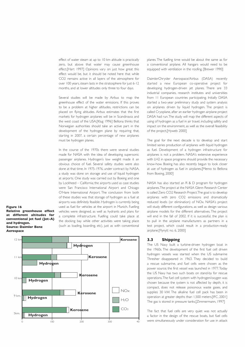
effect of water steam at up to 10 km altitude is practically zero, but above that water may cause greenhouse effect.[Hart 1997] Opinions vary on just how great this effect would be, but it should be noted here that while CO2 remains active in all layers of the atmosphere for over 100 years, steam lasts in the stratosphere for just 6-12 months, and at lower altitudes only three to four days.
Several studies will be made by Airbus to map the greenhouse effect of the water emissions. If this proves to be a problem at higher altitudes, restrictions can be placed on flying altitudes. Airbus estimates that the first markets for hydrogen airplanes will be in Scandinavia and the west coast of the USA.[Klug 1996] Bellona thinks that Norwegian authorities should take an active part in the development of the hydrogen plane by requiring that, starting in 2007, a certain percentage of new airplanes must be hydrogen planes.
In the course of the 1970s there were several studies made for NASA with the idea of developing supersonic passenger airplanes. Hydrogen’s low weight made it an obvious choice of fuel. Several safety studies were also done at that time. In 1975-1976, under contract by NASA, a study was done on storage and use of liquid hydrogen at airports. One study was carried out by Boeing and one by Lockheed – California; the airports used as case studies were San Francisco International Airport and Chicago O’Hare International Airport. The conclusion from both of these studies was that storage of hydrogen as a fuel at airports was definitely feasible. Hydrogen is currently being used as fuel for vehicles at the airport in Munich. Fuelling vehicles were designed, as well as hydrants and plans for a complete infrastructure. Fuelling could take place at the docking bay while other activities were taking place (such as loading, boarding, etc), just as with conventional
planes. The fuelling time would be about the same as for a conventional airplane. All hangars would need to be equipped with ventilation in the roofing. [Brewer 1990]
DaimlerChrysler Aerospace/Airbus (DASA) recently started a new European co-operative project for developing hydrogen-driven jet planes. There are 33 industrial companies, research institutes and universities from 11 European countries participating. Initially DASA started a two-year preliminary study and system analysis on airplanes driven by liquid hydrogen. The project is called Cryoplane, after an earlier hydrogen airplane project DASA had run. The study will map the different aspects of using of hydrogen as a fuel in air travel, including safety and impact on the environment, as well as the overall feasibility of the project.[Hyweb 2000]
The goal for the next decade is to develop and start limited series production of airplanes with liquid hydrogen as fuel. Development of a hydrogen infrastructure for airplanes is not a problem. NASA’s extensive experience with LH2 in space programs should provide the necessary know-how. Boeing has also recently begun to look closer at use of hydrogen as fuel in airplanes.[Memo to Bellona from Boeing, 2000]
NASA has also started an R & D program for hydrogen airplanes. The project at the NASA Glenn Research Center is called Zero CO2 Research Project. The goal is to develop airplanes with zero CO2 emissions and dramatically reduced levels (or elimination) of NOx. NASA’s project will study different configurations, as well as design various airplane models for the different alternatives. The project will end in the fall of 2002. If it is successful, the plan is to pull in the airplane manufacturers as partners in a test project, which could result in a production-ready airplane.[Flynytt no. 6, 2000]
3.3 ShippingThe US Navy built a turbine-driven hydrogen boat in the 1960s. The development of the first fuel cell driven hydrogen vessels was started when the US submarine Thresher disappeared in 1963. They decided to build a rescue submarine, and fuel cells were chosen as the power source; the first vessel was launched in 1977. Today the US Navy has two such boats on stand-by for rescue operations. The fuel cell system with hydrogen/oxygen was chosen because the system is not affected by depth, it is compact, does not release poisonous waste gases, and supplies 30 kW. The alkaline fuel cell pack has been in operation at greater depths than 1,500 meters.[IFC, 2001] The gas is stored in pressure tanks.[Zimmermann, 1997]
The fact that fuel cells are very quiet was not actually a factor in the design of the rescue boats, but fuel cells were simultaneously under consideration for use in attack
Figure 16Relative greenhouse effect at different altitudes for conventional jet fuel (Jet-A) and hydrogen.Source: Daimler Benz Aerospace
���
���
���
� ��� ��� ��� ���
�� ���
�� ���
�� ���
� ���
����
�������� ���������� ������
��������
��������
��������
��������
��������
��������
��������
��������
��������
��������

38
submarines. Sweden looked at using fuel cells in submarines in 1960 but felt using hydrogen was too complicated and instead opted for the Stirling engine.
After many decades of experimentation the Germans started a program to develop fuel cells in 1981. In 1988 a converted German Type 205 submarine (previously U1) was tested for one year with very promising results. The conclusions were:-Fuel cells could be run at and above peak performance-Fuel cells had a design which allowed them to be connected in series or parallel,for low or high speed.-Fuel cells can easily be replaced (on one occasion a cell was damaged and it took the crew less than a half-hour to replace it).
In 1994 they decided to build four new 212 submarines. These are hybrids with fuel cells and a diesel motor. The hydrogen is stored in metal hydride. This is considered an in-between phase towards pure fuel cell submarines. HDW, Howardswerke-Deutche Werft in Kiel, which backed this project, is now working with Canadian Ballard to build a 213 submarine, an Air Independent Propulsion (AIP) vessel based solely on PEM fuel cells and hydrogen/oxygen. The hydrogen in these boats will be stored in metal hydride tanks.[Sattler, 1999]
Russia is also supposed to have converted a diesel driven submarine to fuel cells. This was reportedly done in 1991.[Zimmerman, 1997].
Maritime Hydrogen Technology Development Group in the USA (including among others California Air Resources Board and California Environmental Protection Agency) plans to build and integrate a hydrogen-driven maritime transportation system. A study this group has done for the U.S. Department of Energy concludes that hydrogen can be used economically in maritime transportation with minimal investment in the fuel infrastructure. A hydrogen taxi boat with a turbine motor was launched in 2001, and a fuel cell boat is in the development stage. Hydrogen will initially be stored in lightweight pressure tanks. The goal is to operate an entire fleet of fishing boats and ferries.
Hydra, a passenger boat with 7.5 kW alkaline fuel cells and room for 22 passengers, was launched in the summer of 2000 in Germany. There is also an open 19 ft. boat with batteries and 2.5 kW PEM fuel cells on the market.
In Iceland there is a strong interest in converting their fishing fleet to hydrogen power to save money and reduce CO2 emissions. Norsk Hydro, Shell and DaimlerChrysler are expected to get involved in this project through a company called Icelandic New Energy. Iceland has about the cheapest electricity in the world, and electricity production
is based on renewable energy. Hydrogen produced in Iceland would therefore be much less expensive than importing oil. There are also several other studies on the use of fuel cells in ships and submarines; one such study was done by MARAD USA in 1998 involving a container ship. In England the Royal Navy is considering using fuel cells as an alternative to mainland power. Fuel cells can easily be installed as aggregates in ships as a power supply in port instead of the extremely polluting diesel generators currently in use. A newly started EU project called FCSHIP will also look at fuel cells for marine applications.
On quite another tack, changeover to use of electricity in port should be a standard requirement for the shipping industry.
3.4 Space travelPEM fuel cells were first used in the seven space ships in NASA’s Gemini program from 1962 to 1966. Performance and life expectancy for PEM fuel cells were limited because of the membranes available at that time. There were also problems with the water treatment system.Alkaline fuel cells were used in the programs: Apollo, Apollo-Soyuz and Sky Lab. The fuel cell system was developed by Energy Conversions and Pratt Whitney, with input from F.T. Bacon. Three 28 volt power units supplied electricity to the command and service modules onboard Apollo. Each unit supplied 1.5 kW and weighed 125 kg using liquid hydrogen and oxygen. The three power units operated in parallel, and even if two should stop running, the spacecraft would be able to return safely. In the course of 18 missions and over 10,000 hours in operation there was never an accident involving the fuel cell system in flight.
Today’s space shuttles have three 12 kW fuel cells which supply it with all electrical power onboard. Only one of these is necessary to assure a safe landing. The water produced in the electro-chemical reaction between hydrogen and oxygen in the fuel cells is used as both drinking and cooling water. Each power unit weighs 130 kg. and consists of 96 fuel cells with potassium hydroxide electrolytes. The fuel cells in the space shuttles have been in operation for almost 80,000 hours in 98 missions.[IFC 2000]
The space shuttles also use hydrogen as fuel in the main engines (SSME) during take-off.
Hydrogen powered ships will be a very environmentally friendly means of transport for the future. The shipping sector has enjoyed a virtual amnesty from environmental regulations of air emissions. It is Bellona’s opinion that shipping must now be placed under the same strict standards as other transportation sectors.

3.5 InfrastructureThis section will cover various studies and surveys which support the fact that in an integrated solution for energy, transportation and the environment, hydrogen is the energy carrier that is the most attractive and commercially viable option right now. There are many who say that lack of an infrastructure and the high costs of development are the reasons that hydrogen is not feasible as an energy carrier in the near future. One example is a study done by Arthur D. Little in 1992, where they calculated a total cost of USD 95 billion to develop an infrastructure for hydrogen for 25 million vehicles. This highly exaggerated figure is often quoted in technical articles.[Derby 1998] Lovins (1999) estimates that an infrastructure for hydrogen can be developed in the USA for approximately USD 4 billion. But both of these conclusions are based on suppositions that are not consistent with current circumstances.[Lovins 1999]
The transportation sector is undoubtedly the most challenging when considering the “zero emissions criteria” for the future. The problem is that this sector consists of many small inefficient entities with heavy demands for reasonable driving ranges. The vehicles of the future should also be just as mechanically sound, flexible and economical
as those of today – which also means that the consumer shouldn’t necessarily be expected to pay a higher price for sustainable mobility.
The transportation sector has also considered several alternatives for fuel (Borusbay og Nejat 1989; EIA, 1994; Ogden, 1995; Ogden et al, 1998; Thomas et al, 1998a), all of which prove that hydrogen is the best choice – not just because it is a “zero emission solution”, but also because it will help in reducing the complexity of vehicles which use the fuel directly, and that fuel cells are suitable for a wider range of freight types. Roughly speaking, it is estimated that the efficiency for vehicles will increase from 20% to 40% when the changeover is made from conventional gasoline or diesel to hydrogen and fuel cells.
Berry (1996), Amos (1998), Padró and Putsche (1999) and Lovins (1999) have all made estimations on developing a hydrogen infrastructure. A detailed study by Ogden (1999) for California is based on a combination of smaller steam reforming filling stations and electrolysers for producing hydrogen from electricity. At current market price, the cost of producing hydrogen from natural gas is about a third of the cost of electrolysis.
Fuelcell-bus from MAN.(Foto: Kruse)

40
It is also obvious that in the start phase of building an infrastructure it will be necessary to use electrolyser filling stations to get local infrastructures in place in connection with chosen demonstration projects. One typical group in the Oslo area might be Gardermoen, the harbour and Fornebu. These could then be connected to similar projects in Telemark and Vestfold, centralised around the industrial activities in the Grenland area. Bellona has also pointed out that if we wished to develop an extensive network of 65 hydrogen filling stations at 100 kilometer intervals, to cover all of southern Norway by 2006, this could be done with just a small portion of the current CO2 tax (ref. to highlighted text).
The chicken, the egg and the filling stations
No one would want to buy a car if you couldn’t fill it up, and no one wants to build filling stations if there are no customers to fill up. This is often presented as a major problem, but this paradox is actually not so difficult to solve.
What is needed is a network of small filling stations so that it is possible to get anywhere by hydrogen car. If stations were to be placed at 100 kilometre intervals from Steinkjær and southward, we would have a fully functional network in Southern Norway. The stations would be based on electrolysis and have a capacity of 100 cars a day which is enough to supply a few thousand cars.
The stations have been designed and are available at a cost of NOK 10 million (conservative estimate); the question is how can this be financed.
In Norway we pay 0.09 USD in CO2 tax for every liter of gasoline, and 0.06 USD for every liter diesel. If we take 0.006 USD of this over a 5 year period, we could finance such a network. This also includes a 50% safety margin.
This would solve the problem. If the Norwegian Parliament would allocate this amount every year starting in 2003, the infrastructure could be operational when the cars are ready for sale to the public. This proposal poses no risk, since the money would not be used until the cars are in the final development stage.

4 The Energy SectorThe energy sector, as with transportation, is a heavy user of fossil fuels. 85% of the world’s commercial sale of energy is based on fossil fuels. About 35,000 TWh – 1/3 of the world’s total primary energy consumption – is used to produce electricity. 2/3 of the energy is lost in the transformation, so the output is only 12,000 TWh effective electricity. Generating capacity is currently 3,000 GW and is expected to increase to 5,000 GW by 2020.
If we were to replace all existing power plants with the most energy efficient designs without increasing capacity, emissions would be reduced by 30%. Through expected increase in power consumption, emissions would still increase considerably. If all use of coal and oil for electric power is replaced with gas, the emissions would be further reduced. This is however not really realistic, nor would it be sufficient to meet the IPCC’s recommendation of at least 60% reduction of greenhouse gases caused by man.
A transition to renewable energy is therefore necessary, but production of solar panels and wind turbines to achieve this would also require an increase in energy consumption in the transitional phase.
Fossil fuel power, utilising a CO2 treatment method which prevents release into the atmosphere, could be a workable solution to provide power in the transition. “CO2 free” fossil fuel power used to produce wind turbines and solar panels would represent a sensible usage of fossil hydrocarbons.
4.1 Renewable energy and hydrogenThe main goal is a renewable energy system. The potential is enormous. The amount of solar energy which reaches the earth in the course of a year approximately equals 15,000 times the world’s annual energy consumption. Just in Argentina’s Patagonia district there is enough wind to produce enough hydrogen to replace all oil production in the world. Gamello et al. has looked at how to utilise the wind resources in this area, where they currently lack, or have a very poor, electrical grid. The wind energy can be used to produce liquid hydrogen, which can be exported to Japan and Europe, for example [Gamallo et al. 2001].
Areas which are specially well suited for large scale solar power production because of high sun exposure is at the equator in the Americas, Sahara, South Africa, Middle East and Australia. Here there are large areas with solar radiation close to 2,500 kWh/m2 annually. Nitsch et al. has mapped the areas that are best suited and studied how hydrogen produced from solar power can be distributed to the heavily populated urban centers by pipeline from North Africa to Europe [Winter et al 88].
USA is the largest consumer of energy and the greatest emitter of greenhouse gases in the world. An area partially covered by permanently installed, flat solar panels with an efficiency factor of 10% and a size of 166 x 166 km (27,556 km2) in the Nevada desert would be able to supply all the energy consumed in the USA. This is equal to only 0.4 % of the available land area in the USA. A comparable amount of land to supply Mexico would be only 1,100 km2. If wind power and geothermal energy are used in addition, the areas needed would be much smaller.[Turner 1999]
4 Solar panels and wind turbines have become very economical to produce and prices are expected to sink even lower in the next decade. Solar panels and windmills are quite competitive compared to polluting technologies in many places.
The solar panel market is now increasing so quickly that there could soon be a lack of usable silicon. Traditionally solar panel silicon is made from waste products from the electronic industry’s silicon. Alternative processes to make solar panel silicon which produces the correct purity with low energy usage, thereby reducing production costs, are under development. The current energy payback time for crystalline solar panels is 2-5 years, and for amorphous silicon solar cells 1-3 years. The goal is to reduce the amount of energy used in production to only a tenth of today’s consumption.
Another way of utilising solar energy is solar thermal systems. A liquid is heated up which then powers steam turbines or a sterling engine is used. In the Mojave Desert in California, nine plants producing 355 MW have been in operation for several years. The newest section of this system produces power at 0.06 USD/kWh. Wind turbines have become cheaper and better and it is possible to produce wind power at 0.025 USD/kWh in certain areas with good wind conditions.
There are approximately 2 billion people today who do not have access to an electric power grid. This would be a natural market for solar panels. There are currently many thousand solar panel systems installed around the world. In Norway alone, there are over 100,000 such systems, used mostly in cabins and lighthouses. These systems have traditionally used lead batteries for storing energy, as hydrogen systems have so far been too expensive. Lead batteries are still relatively inexpensive for small systems; but for larger ones, where there is a need for seasonal storage or fuel gas, a hydrogen system or a hybrid solution could be of interest.
Hydrogen can play an important role in the storage and transport of energy from renewable energy sources such as sun and wind. This would first take place in small stand-alone power systems (SAPS) and eventually larger systems. Fuel cell systems are rapidly on the way into the market, especially as emergency power back-up systems. Several hundred fuel cell systems are currently in operation around the world in everything from small households that produce electricity and hot water to huge systems producing megawatts.
4.2 Stationary fuel cell systemsFuel cells have several advantages over turbines. High temperature fuel cells can use natural gas or biogas directly, without external reforming of the gas to hydrogen. The exhaust consists exclusively of CO2 and water, where the
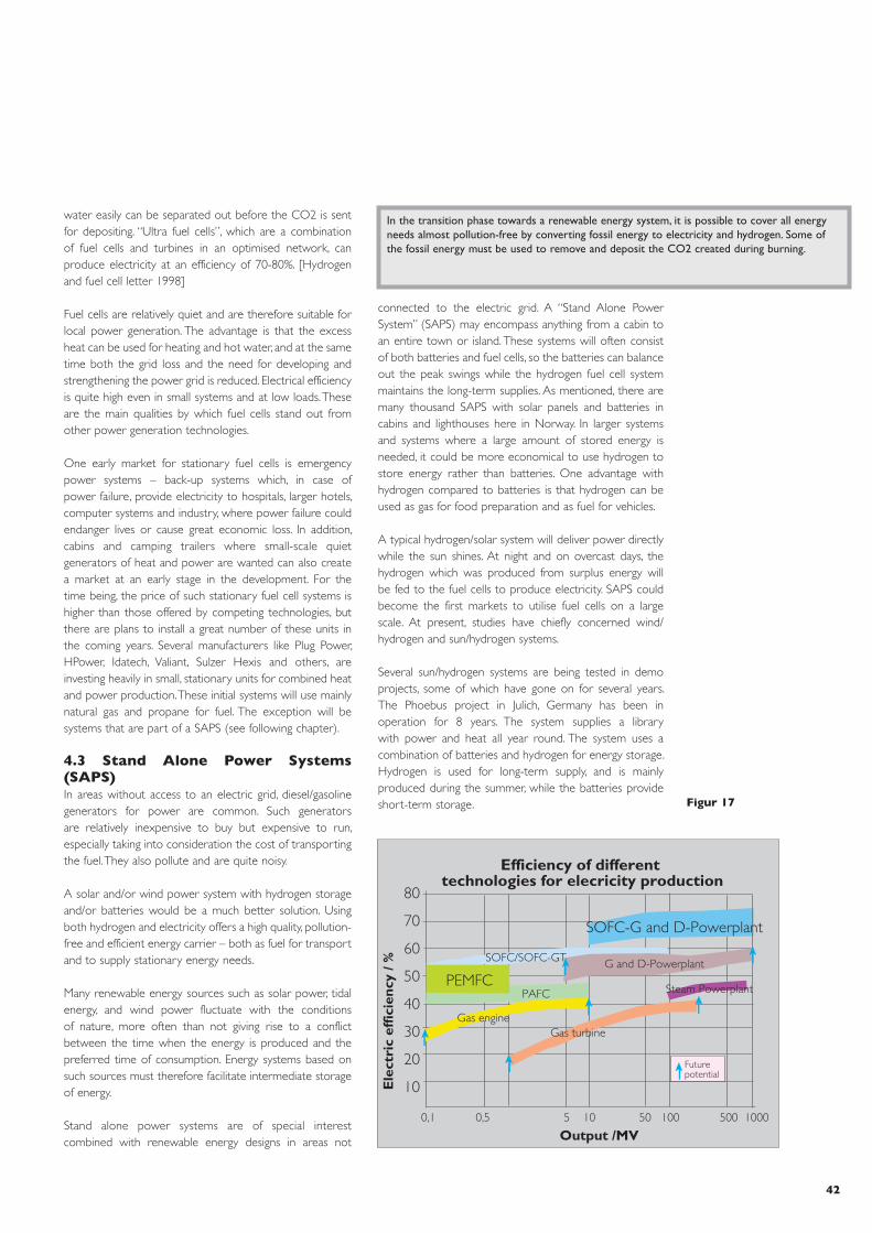
42
In the transition phase towards a renewable energy system, it is possible to cover all energy needs almost pollution-free by converting fossil energy to electricity and hydrogen. Some of the fossil energy must be used to remove and deposit the CO2 created during burning.
���������� �� ��������������������� ��� ���������� ����������
������ ���
���
����
���
�����
���
��
��
��
��
��
��
��
��
��
������ ��� ������������
�����
������������ � ��� ������������
���� ����� ����������
���������������
��� ��� � �� �� ��� ��� ����
��� ��������� �������
Figur 17
water easily can be separated out before the CO2 is sent for depositing. “Ultra fuel cells”, which are a combination of fuel cells and turbines in an optimised network, can produce electricity at an efficiency of 70-80%. [Hydrogen and fuel cell letter 1998]
Fuel cells are relatively quiet and are therefore suitable for local power generation. The advantage is that the excess heat can be used for heating and hot water, and at the same time both the grid loss and the need for developing and strengthening the power grid is reduced. Electrical efficiency is quite high even in small systems and at low loads. These are the main qualities by which fuel cells stand out from other power generation technologies.
One early market for stationary fuel cells is emergency power systems – back-up systems which, in case of power failure, provide electricity to hospitals, larger hotels, computer systems and industry, where power failure could endanger lives or cause great economic loss. In addition, cabins and camping trailers where small-scale quiet generators of heat and power are wanted can also create a market at an early stage in the development. For the time being, the price of such stationary fuel cell systems is higher than those offered by competing technologies, but there are plans to install a great number of these units in the coming years. Several manufacturers like Plug Power, HPower, Idatech, Valiant, Sulzer Hexis and others, are investing heavily in small, stationary units for combined heat and power production. These initial systems will use mainly natural gas and propane for fuel. The exception will be systems that are part of a SAPS (see following chapter).
4.3 Stand Alone Power Systems (SAPS)In areas without access to an electric grid, diesel/gasoline generators for power are common. Such generators are relatively inexpensive to buy but expensive to run, especially taking into consideration the cost of transporting the fuel. They also pollute and are quite noisy.
A solar and/or wind power system with hydrogen storage and/or batteries would be a much better solution. Using both hydrogen and electricity offers a high quality, pollution-free and efficient energy carrier – both as fuel for transport and to supply stationary energy needs.
Many renewable energy sources such as solar power, tidal energy, and wind power fluctuate with the conditions of nature, more often than not giving rise to a conflict between the time when the energy is produced and the preferred time of consumption. Energy systems based on such sources must therefore facilitate intermediate storage of energy.
Stand alone power systems are of special interest combined with renewable energy designs in areas not
connected to the electric grid. A “Stand Alone Power System” (SAPS) may encompass anything from a cabin to an entire town or island. These systems will often consist of both batteries and fuel cells, so the batteries can balance out the peak swings while the hydrogen fuel cell system maintains the long-term supplies. As mentioned, there are many thousand SAPS with solar panels and batteries in cabins and lighthouses here in Norway. In larger systems and systems where a large amount of stored energy is needed, it could be more economical to use hydrogen to store energy rather than batteries. One advantage with hydrogen compared to batteries is that hydrogen can be used as gas for food preparation and as fuel for vehicles.
A typical hydrogen/solar system will deliver power directly while the sun shines. At night and on overcast days, the hydrogen which was produced from surplus energy will be fed to the fuel cells to produce electricity. SAPS could become the first markets to utilise fuel cells on a large scale. At present, studies have chiefly concerned wind/hydrogen and sun/hydrogen systems.
Several sun/hydrogen systems are being tested in demo projects, some of which have gone on for several years. The Phoebus project in Julich, Germany has been in operation for 8 years. The system supplies a library with power and heat all year round. The system uses a combination of batteries and hydrogen for energy storage. Hydrogen is used for long-term supply, and is mainly produced during the summer, while the batteries provide short-term storage.

The word “polygeneration” is used more and more to describe the benefits of integrated solutions. This involves decarbonizing the hydrocarbon fuel, transforming it to products such as hydrogen, synthesis gas, ammonia, CO2, electricity and heat. The turbines become power units integrated and optimised in several processes.[Pacala and Socolow 2000] It should be emphasised that it is not only natural gas which is suitable for polygeneration.
The market for these alternative products is in the establishment phase. The EU has set strict standards on the quality of existing fuel, while the quality of crude oil is getting worse and oil companies wish to use more of what previously was waste products, or “bottom-of-the-barrel”. This means using more hydrogen in the refining process. In the future, the EU is also considering making use of hythane (i.e. natural gas mixed with up to 15% hydrogen). These are two favourable methods that can aid in increasing the marketability of hydrogen as well as improving the quality of air and reducing emissions of CO2.
There is a growing acceptance of the use of CO2 as pressure support in ageing oil fields in the North Sea. Both oil companies [CCP 2001] and governments are showing interest towards considering the building of a CO2 infrastructure [Hustad 2000], which would reduce transportation and depositing costs.[Wildenborg 2000] This portion represents about a third of the total removal costs.[Undrum et al. 2000] Cost reductions here would contribute towards improved profitability in future projects, while the infrastructure would also increase the possibilities of using CO2 in several reservoir projects.
4.5 ElectronicsFuel cells will probably get their major breakthrough as replacements for batteries. There are those who predict that fuel cells will replace batteries within 5 years. The transition to the next generation of broad band cell phones and powerful handheld computers will require energy storage greater than what today’s lithium batteries can supply. Lithium batteries are already reaching their limit of energy density. This is becoming a limiting factor for producers of electronics while consumers are demanding greater processor capacity and battery life. Fuel cell systems are lighter than batteries when comparing the amount of stored energy per kg. Fuel cells will be compatible with cell phones, laptops, video cameras, etc. The market potential is huge and will enable mass production of fuel cells. This is already happening in a variety of prototypes from various suppliers, including the electronics giant, Sony. This is also a market willing to accept a much higher cost per kW output than the car industry and the stationary markets. Fuel cells will therefore more rapidly become competitive in this particular market.
Portable electronic equipment may become the first large market for fuel cells.
Ballard has now begun shipping small, stationary 1.2 kW electric fuel cell stacks to producers of generators. These generators will be on the market by 2003
Wind/hydrogen is being tested in Stralsund, Germany, and there are plans for several large wind/hydrogen plants in Norway and Argentina. The Institute for Energy Technology at Kjeller in Norway has developed a software program for simulating consumption and production at a SAPS, which can be useful in designing the storage capacity needed in such systems.
4.4 CO2 removalFor several years Bellona has pointed out that Norway, with its geographical location near the large energy market in Europe and capacity for depositing CO2 in geological formations in the North Sea, is in a unique position where energy resources are concerned.[Palm, T. et al. 1999; SACS 2000] The amount of oil that Norway exports make up 4% of the total world consumption. Furthermore, Norway possesses approximately 40% of Europe’s nearby gas reserves and is capable of depositing CO2 volumes equalling several hundred years of emissions from the European power and industry market. This supports the supposition that Norway has a competitive advantage as a major supplier of decarbonized energy, while simultaneously taking care of Europe’s CO2 emissions from traditional fossil fuel power generation.
Williams (1996), Socolow (1997) and Blok et al. (1997) are just a few of many authors who have pointed out the possibilities inherent in decarbonization of fossil energy, with subsequent use of CO2 as pressuriser in existing oil reservoirs.[Holt et al. 1995] The concept Norsk Hydro presented in April of 1998 (“Hydrokraft”) was partially a continuation of these ideas.[Hustad 2001] Norsk Hydro recommended reforming natural gas into a hydrogen rich fuel gas which could be used in conventional gas turbines.[Todd and Batista 2000] CO2 was to be removed and 4 million tons re-injected as pressure support in the Grane oil field. There were advantages in such a large plant with an output of 1,200 MW and 10 TWh, but the project was unprofitable at the time. However, the concept is still subject to on-going study.

44

5 a case of detonation as a result of the direct blows. Only in two of the tests – using large amounts of liquid oxygen and a heavy explosive discharge – was it possible to detonate the hydrogen. The conclusion from these tests were that hydrogen is difficult to detonate in open air, and that it is a relatively safe fuel compared to other alternatives.
In 1980, Lockheed Martin and Arthur D. Little made two parallel studies for NASA Lewis Research Centre to determine the safety risks if a hydrogen plane should crash. The hydrogen plane was compared to a similar plane using conventional fuel, and the planes were put to the same test.
The scenario was based on a 400-seat passenger airplane, and included a crash landing and a plane crash. The conclusion was that liquid hydrogen caused less damage than the normal jet fuel, especially since hydrogen evaporates quickly, burns rapidly and gives off little heat. If a hydrogen plane crashes and the fuel starts burning, the chances for survival are probably greater than in a regular airplane.[Brewer 1991]
When new hydrogen-based systems are launched, more comprehensive safety systems will be built in compared to existing gasoline systems. The BMW 750 hl (see 3.1.1), which uses hydrogen, has a sunroof and windows which automatically open up long before the hydrogen level in the car reaches 4%.[Hart 1998] Actual crash tests of these vehicles and computer simulations show that these cars are safe in accident situations.[BMW 2001]
Gasoline has been the preferred fuel for cars for over a hundred years, despite the considerable number of accidents where gasoline fires take the lives of people. We are accustomed to the risks involved in gasoline, while hydrogen has undeservedly been given a bad name. The following describes some accidents and circumstances that many associate with hydrogen.
Hydrogen – Air mixMixtures between 4 and 75% are flammable, and mixtures between 18 and 59% are explosive.[Brewer 1991] Likewise, gasoline is explosive between 1.1 and 3.3 % - in other words a much lower burning point than for hydrogen. In the majority of accidents it’s the lower point that is decisive. It is very difficult to detonate hydrogen in open air. This has to do with the fact that hydrogen is much lighter than air (14.4 times) and rises at a speed of 20 m/s. Leak detectors, ventilation and other security systems must be installed if hydrogen is to be used indoors, such as automotive workshops.[Swain 1998]
SafetyEnergy carriers used as fuel are by definition explosive and fire hazards. Different types of fuel have quite varying physical properties, and must therefore be handled differently. No fuel system can be described as totally safe, but the risk of accidents can be reduced significantly by appropriate storage, handling and transportation methods. Safety is important in a large-scale energy infrastructure. Bellona’s viewpoint is that hydrogen is no more or less dangerous than any other energy carrier and furthermore that hydrogen has properties that in certain areas make it safer than other energy carriers: it is not poisonous, and has the ability to dissipate quickly into the atmosphere because of its light weight compared to air.
A hydrogen flame burns quickly and emits very little heat (hydrogen radiates only 10% of the heat from hydrocarbons per comparable unit of energy). This means that a hydrogen fire will do much less damage to the immediate surroundings than a gasoline fire, while consequently creating less damaging gases caused by the burning of “secondary” materials.
Other properties of hydrogen necessitate special considerations when handling. Hydrogen consists of small molecules, which require special qualities in materials used in storage and transportation means. Hydrogen creates flammable and explosive mixtures of air over a broad spectre (see Table 5). These mixtures need very little
energy to ignite. Ventilation is therefore an important factor in areas where hydrogen is used.
At the end of the 1950s, Lockheed Aerospace carried out experiments to test detonation properties of liquid hydrogen (LH2). In a series of 61 tests, where LH2 in thermoses were put under great physical stresses (such as crushing the thermos with a heavy object), there was never
There is very little likelihood that hydrogen will explode in open air, since it will quickly rise upwards due to its lightness. This is the opposite of what we find for heavier gases such as propane or gasoline fumes, which, hovering near the ground, constitute great danger for explosion.
Table 5Some safety statistics for hydrogen and other fuels
Characteristic Hydrogen Natural gas Gasoline
Lower heating value (KJ/g) 120 50 44,5Self-ignition temperature (ºC) 585 540 228-501Flame temperature (ºC) 2 045 1 875 2 200Flammability limits in air (vol %) 4-75 5,3-15 1,0-7,6Minimum ignition energy in air (uJ) 20 290 240Detonability limits in air (vol %) 18-59 6,3-13,5 1,1-3,3Theoretical explosive energy (kg TNT/m3 gass) 2,02 7,03 44,22Diffusion coefficient in air (cm2/s) 0,61 0,16 0,05
5

46
Town gasTown gas, which was previously piped into the majority of the larger cities (like Oslo), contained about 50% hydrogen. The town gas was used for cooking, heating and lighting. Town gas also contained large amounts of CO, which can cause suffocation. Town gas was made from coal and for the most part has been replaced with natural gas, but it is still used in China, South Africa and other areas where natural gas is expensive or unavailable.[Winter et al. 1988]
Fusion / Hydrogen BombsA fusion is an amalgamation of two light atom nuclei to a heavier atom nucleus. The source of energy on the sun is the continual fusion of deuterium (hydrogen atom with one neutron and one proton in the nucleus) into helium. The reaction requires high pressure and temperatures of several million degrees.[Henriksen 1993] In a hydrogen bomb, or neutron bomb, a nuclear fusion takes place. In a hydrogen bomb lithium-6-deutride [6Li2H] is packed into a conventional atom bomb to reach a high enough temperature and pressure level. It is under no circumstance possible to come anywhere close to a fusion reaction with regular hydrogen, in a car accident or plane crash.
The Hindenburg AccidentIn 1936 the Hindenburg airship was finished. It was 245 meters long and was driven by four 1,100 horsepower Daimler-Benz diesel engines, reaching a speed of 135 km/h and ranging 14,000 km. The blimp could carry 50 passengers and had cabins, a bar, a dining room and walkway as well as large panorama windows and lounges. It flew a regular route between Germany and USA for DELAG and transported over 1,000 passengers in 1936 in 10 round-trip tours over the Atlantic Ocean; it took 65 hours going east and 52 hours going west.
On the evening of May 6, 1937, the Hindenburg crashed in Lakehurst, New York. Of the 97 passengers onboard, 35 lost their lives. One person in the ground crew of 200 was killed when one of the motors fell out. Of those that died, 27 had jumped out in panic while still in the air and the other 8 died due to burn injuries from burning diesel. An investigative commission engaged by the Zeppelin company concluded that some hydrogen had leaked out from the internal tanks and was ignited by a spark.
For several years now Addison Bain has carried out extensive investigations to try to find out exactly what the cause of the accident was. The conclusion, after having analysed bits of the materials used in the canvassing around the blimp, was that the Hindenburg burned because this material was extremely flammable. The fire was sparked by static electricity as the result of an error in design. The hydrogen gas used for buoyancy had no direct influence on the accident. Bellona recommends reading Bain’s report, which is available on the Internet at http://www.dwv-info.de/pm/hindbg/hbe.htm.[Bain and Schmidtchen 2000]
The Challenger AccidentThe American space administration, NASA, has had experience with the application and use of hydrogen since 1960. NASA has not experienced any serious accidents connected to hydrogen, even though it were erroneously associated with the explosion onboard the Challenger in 1986. The Challenger accident was caused by failure of the sealing mechanisms in the solid fuel system, which provided extra propulsion during takeoff. The accident had nothing to do with the use of hydrogen in the main engine (SSME).[Hart, 1998]
Gasoline car to the rightHydrogen car to the leftA picture from a video which compared fire from a leak in a gasoline engine car and the same kind of leak from a hydrogen car. The pictures are taken at one minute after ignition. The hydrogen flame has begun to subside, the gasoline fire is intensifying. After 100 seconds, all the hydrogen was gone and the interior of the car was undamaged. The gasoline car continued to burn for a long time and was totally damaged.[Swain 2001]

Borusbay, C. and Nejat Veziroglu, T., (1989). ”Hydrogen as a Fuel for Spark Ignition Engines,” Alternative Energy Sources VIII, Volume 2, Research and Development, Hemisphere Publishing Corporation, New York, NY.Bose,T.K and Gingras, (2000). ”Removing Unnecessary Barriers through the Activities of ISO/TC 197 on Hydrogen Technologies”, Hydrogen Energy Progress XIII, International Association for Hydrogen Energy, Vol.1.Brewer, G.D., (1991). ”Hydrogen Aircraft Technology”, ISBN 0849358388, CRC Press. (See web address www.crcpress.com).Calstart (1999), http://www.calstart.org Cancarb, (2001). Cancarb Ltd, Medecine Hat, Alberta, Canada. (See web area www.cancarb.com).Cheny, D. et al., (2001). ”Reliable, Affordable, and Environmentally Sound Energy for America’s Future”, National Energy Policy Development Group, Washington, DC, 16 May. (Can be downloaded from internet address: http://www.whitehouse.gov/energy/National-Energy-Policy.pdf ).Czernik, S., (2000). ”Hydrogen from Biomass by Catalytic Steam Reforming of Fast Pyrolysis Oil”, PyNe Newsletter, Nr. 8, pp. 6–7. (Available as a pdf file from web address: http://www.pyne.co.uk/pyne/files/375.pdf).Czernik, S., French, R., Feik, C. and Chornet, E., (2001). ”Production of Hydrogen from Biomass-Derived Liquids ”, Proceedings of the 2001 DOE Hydrogen Program Review, NREL/CP-570-30535. Derby, R., (1998). ”Unleashing Fuel Cells Holy Grail”, Fuel Cells Bulletin, Vol.1, No.3, pp.6–8, December.Dillion, (1999). ”Carbon nanotube materials for hydrogen storage”, Proceedings of the 1999 DOE Hydrogen Program Review.DOE 15.01.2001 Record Run by Solid Oxide Fuel Cell Comes To Successful Conclusion.http://www.fe.doe.gov/techline/tl_fuelcell_netherlands.htmlDOE, (1999). ”Carbon Sequestration State of the Science: A Working Paper for Roadmapping Future Carbon Sequestration R&D”, U.S. Department of Energy, Washington, DC. (Available from internet address: http://www.fe.doe.gov/coal_power/sequestration/.DOE, (2000) ”DOE Hydrogen Program 2000” http://www.doe.gov DOE, Westinghouse to Continue Development of Solid Oxide Fuel Cells, www.gnet.org/filecomponent/17424.htm EIA, (2000). ”Annual Energy Outlook 2001 with Projections to 2020”, Energy Information Association, U.S. Department of Energy, Washington, D.C., December. (Available from internet address: www.eia.doe.gov/oiaf/aeo/ ).EIA, (1994). ”Alternatives to Traditional Transportation Fuels: An Overview”, Rapport DOE/EIA-0585/O, Energy Information Association, U.S. Department of Energy, Washington, D.C., June.
ReferencesAmos, W., (1998). “Costs of Storing and Transporting Hydrogen,” Report NREL/TP-570-25106, National Renewable Energy Laboratory, (220 pp., USD 47.00, NTIS Order No. DE 00006574).Automotive World, (2000), March.Asada et al., (2000). “IEA Agreement Task 15”, Hydrogen Progress III IAHE.Azar, C., Lindgren, K. and Anderson, B.A., (1998). “Hydrogen or Methanol in the Transportation Sector?”, Department of Physical Resource Theory, Chalmers University of Technology, Gothenburg, Sweden.Bain, A. and Schmidtchen, U., (1999). “Afterglow of a Myth: Why and How the Hindenburg Burnt” (See html address: http://www.dwv-info.de/pm/pe00hb.htm ).Bansal, A., Beach, J., Collins, R., Khaselev, O. and Turner, J.A., (1999). “Photoelectrochemical Based Direct Conversion Systems for Hydrogen Production”, National Renewable Energy Laboratory. Proceedings of the 2000 DOE Hydrogen Program Review, (can be downloaded as a pdf file from web address: http://www.eren.doe.gov/hydrogen/pdfs/26938f.pdf).Bauen & Hart, 1999. Assessment of the environmental benefits of transport and stationary fuel cell. Journal of Power Sources 86 (2000) 482-494Benemann, (1998). “Process analysis and economics of Biophotolysis of Water”, IEA Technical Report.Berry, G., (1996). “Hydrogen as a Transportation Fuel: Costs and Benefits,” Lawrence Livermore Laboratory, UCRL-ID-123465, March 1997.Blok, K., Williams, R., Katofsky, R. and Hendriks, C. (1997). “Hydrogen Production from Natural Gas, Sequestration of Recovered CO2 in Depleted Gas Wells and Enhanced Natural Gas Recovery,” International Journal of Hydrogen Energy, Vol.22, No. 2/3, pp. 161–168.BMW (2000). See web address http://www.bmw.com/BMW (2001). ”Powered by BMW with Sun and Water”, BMW Group.Boeing (2000 ). Private Note to Bellona from Boeing.Brady, J.E., (2000). ”General Chemistry”, ISBN 8251915791, Tapir publishing, Trondheim.Bromberg, L., Rabinovich, A., Alexeev, N. and Cohn, D.R., (1999). ”Plasma Catalytic Reforming of Methane”, Paper PSFC/JA-99-JA-16, MIT, Cambridge, MA. (Available as a pdf file from web address: http://www.pfc.mit.edu/library/99ja/99ja016_full.pdf).Bromberg, L. et al., (1999a). ”System Optimisation and Cost Analysis of Plasma Catalytic Reforming of Hydrocarbons ”, Paper PSFC/JA-99-JA-17, MIT, Cambridge, MA. (Available as a pdf file from web address: http://www.pfc.mit.edu/library/99ja/99ja017_full.pdf).Blomen, L. J. M. J. and Mugerwa, M.N., (1994). ”Fuel Cell Systems”, ISBN 0306441586, Kluwer Academic Publishers, The Netherlands.

48
Gardner, F.J., (199x). ”SOFC Technology Development at Rolls-Royce”, Rolls-Royce Strategic Research Centre.George, R., (199x) ”Status of Tubular SOFC Field Unit Demonstration”, Siemens Westinghouse Power Corp., USA.Ford (1998). ”Ford’s R&D on direct hydrogen fuel cells systems”, EVS-15.Friedlmeyer, G., (2000). ”Test experiences with the Daimler Chrysler Hydrogen- Fuelled Fuel Cell Electric Vehicle NECAR 4” Hydrogen energy progress XIII: International association for hydrogen energy vol. 2.Ercegovic, D.B., (2000), ”Hydrogendrevne fly”, Flynytt magazine no. 6, November 2000. (See web address http://www.flynytt.no/sider/nr-6-00.asp )Fox, J. and Cramer, D., (1997). ”Hypercars: A Market-Oriented Approach to Meeting Life Cycle and Environmental Goal”, Society of Automotive Engineers (SAE), Paper No. 971096, Rapport #T97-5, Rocky Mountain Institute, Old Snowmass, CL.Gamallo, F., (2001) ”Patagonian wind exported as liquid hydrogen”. Proceedings from Hypothesis IV, Vol. 1, Stralsund, Germany, September 2001.Gaudernack (1998), B. ”Hydrogen”, Elektro no. 1 and letter of 29.5.1998 to Bellona.Godfrey, R.B., ”Planar SOFC: The Australian Experience and Outlook”, Ceramic Fuel Cells Limited, Australia. Regenerative Fuel Cell Systems R&D Mitilisky Lawrence Livermore National Laboratory. Haluska, M. et al., (2001). ”Hydrogen Storage in Single Walled Carbon Nanotubes”, Proceedings from 8th European Conference on Solid State Chemistry, Oslo, Norway, July 2001.Harries, J.E., Brindley, H.E., Sagoo, P.J. and Bantges, R.J., (2001). ”Increase s in Greenhouse Forcing Inferred from the Outgoing Longwave Radiation Spectra of the Earth in 1970 and 1997”, vol. 410, pp. 355–357, Nature, March 2001.Hart, D., (1997). ”Hydrogen Power: The commercial future of the ultimate fuel”, ISBN 1853347604, Financial Times Energy Publishing, London, UK.Hart, D. and Bauen, A., (1998). ”Fuel Cells: Clean power, clean transport, clean future”, ISBN 1840830606, Financial Times Energy Publishing, London, UK.Henriksen et al., (1993). ”Stråling og Helse”, Fysisk Institutt, Universitetet i Oslo.Heydorn, B. (1998). ”Hydrogen”, SRI Consulting. Hildrum, (1998). ”Perspektivene for hydrogen til kraftproduksjon, industriell utvikling, i transportsektoren og til husholdningene”. Kværner.Hoffmann, (2000). Hydrogen & Fuel Cell Letter, April 2000Holloway, S., (1997). ”An Overview of the Joule II Project; The Underground Disposal of Carbon Dioxide”, Energy Conversion Management, Vol. 38, Suppl., pp. 193–198.
Holt, T. and Lindeberg, E., (1993). ”CO2 from Industrial Sources as Injection Gas in Oil Reservoirs”, Energy Conversion Management, Vol. 34, No. 9–11, pp. 1189–1196.Holt, T., Jensen J. and Lindeberg, E., (1995). ”Underground Storage of CO2 in Aquifers and Oil Reservoirs”, Energy Conversion Management, Vol. 36, No. 6–9, pp. 535–538.Hustad, C-W. and Bjønnes, G., (2000). ”The Norwegian CO2-Infrastructure Initiative: The Economics and Socio-Economics of using CO2 for Enhanced Oil Recovery in the North Sea Basin”, International Conference on Global Carbon Management, Sequestration Control Technologies and Life Cycle Analysis, Washington, D.C., 13–16 August.Hustad, C-W., (2001). ”The Norwegian CO2 Infrastructure Initiative: A Feasibility Study”. In Proc. Fifth Intl. Conf. on GHG-Control Technologies, pp. 1068–1073. Eds. Williams, D., et al., ISBN 064306672, CSIRO Publishing, Australia. (See web address: www.publish.csiro.au)Hustad, C-W., (2001). ”Review over Recent Norwegian Studies Regarding Cost of Low CO2-Emission Power Plant Technology”. In Proc. Fifth Intl. Conf. on GHG-Control Technologies, pp.1295–1300. Eds. Williams, D., et al., ISBN 064306672, CSIRO Publishing, Australia.Hydro (1999), ”Testing of Nebus in public transport in Oslo and Akershus County, August 1999”, Norsk Hydro 11/23/1999.Hyweb (2001), http://www.hydrogen.orgIEA/Foster Wheeler 1996. ”Decarbonisation of Fossil Fuels” PH2/2 March 1996.IFC, (2001) ”International Fuel Cells” See web address www.ifc.com IPCC, (2001). ”Special Report on Emission Scenarios”, Intergovernmental Panel on Climate Change, Geneva, Switzerland. http://www.grida.no/climate/ipcc/emission/index.htm ).King, (2000). Journal of Power Sources, Vol. 86/1-2 Elsevier Klug, H., (1996). ”Environmental Compatibility of Cryoplane” Daimler-Benz Aerospace, Airbus. Kofstad, P., (1992). ”Uorganisk kjemi”, ISBN 8251830427, Universitetsforlaget, Oslo.Lovins, A.B. and Lovins, L.H., (1997). ”Climate: Making Sense and Making Money”, Rocky Mountain Institute, Old Snowmass, CL. November. (Available from web address: www.rmi.org ).Lovins, A.B., (1999). ”A Strategy for the Hydrogen Transition”, 10th Annual U.S. Hydrogen Meeting, Vienna, Virginia, 7–9 April. (Can be downloaded as a pdf file from web address: http://www.rmi.org/images/other/HC-StrategyHCTrans.pdf ).MTU, (2001), ”New technologies – shaping the future”. Brochure from MTU.MHTX, (2001). ”Manhattan Scientifics”. (See web address: www.mhtx.com).

Miller, E. and Rocheleau, R., (2000). ”Photoelectrochemical Hydrogen Production”, Hawaii Natural Energy Institute. Proceedings of the 2000 DOE Hydrogen Program Review, (Can be downloaded as a pdf file from web address: http://www.eren.doe.gov/hydrogen/pdfs/28890s.pdf).NREL, (2000). Proceedings of the 2000 DOE Hydrogen Program Review, (See web address: http://www.eren.doe.gov/hydrogen ).NFR, (2001). ”Nye fornybare energikilder”, Norges Forskningsråd, NVE.NOU (1998) ”Energi- og kraftbalansen mot 2020”, Norges offentlige utredninger no. 11, Statens forvaltnings-tjeneste.Nytek, (2000). ”Hydrogensamfunnet”, SINTEF Energiforskning AS.Ogden, J. and Nitsch, J., (1993). ”Solar Hydrogen: Renewable Energy – Sources for fuels and electricity”, Island Press, Washington D.C.Ogden, J., (1995) ”Development of Refuelling Infrastructure for Hydrogen Vehicles”, presentation at South Coast Air Quality Management, CA – District Fuel Cell Task Force Meeting.Ogden, J., (1999). ”Developing an infrastructure for hydrogen vehicles: a Southern California case study”, International Journal of Hydrogen Energy, Vol. 24, pp. 709–730.Ogden, J., Kreutz, T. and Steinbugler, M., (1998). ”Fuels for fuel cell vehicles: Vehicle design and infrastructure issues.”, SAE Technical Paper Series – 982500, Warrendale, PA.Opel (2000). (See web address: www.opel.com ).Pacala, S. and Socolow, R., (2000). ”A Carbon Mitigation Initiative at Princeton University: A Proposal to BP-Amoco”, Princeton University, Princeton, NJ, March.Padró, C.E.G. and Putsche, V., (1999). ”Survey of the Economics of Hydrogen Technologies”, Rapport NREL/TP-570-27079, National Renewable Energy Laboratory, September.Palm, T., Buch, C., Kruse, B. and Sauar, E., (1999). ”Green Heat and Power”, Bellona Report no. 3.Poweronline, Largest Solid Oxide Fuel Cell to Date Passes Factory Test at Westinghouse, www.poweronline.com/industry-news/19971110-308.htm Princeton University 1997. ”Fuels Decarbonization and Carbon sequestration”, http://www.princeton.edu/~ceesdoe RSWG, (1990). ”Emission Scenarios: Prepared for the IPCC Response Strategies Working Group”, Intergovernmental Panel on Climate Change, Geneva, Switzerland.SACS, (2000). ”CO2 Storage in Saline Aquifers”, Session at Fifth International Conference on Greenhouse Gas Control Technologies, Cairns, Australia, 13–16 August. (See also web address: http://www.ieagreen.org.uk/sacshome.htm
Sattler, (1999). ”Journal of power sources”, Elsevier Vol. 86/1-2.Science, (2000). Nr 3, mars.SFT, (1998). ”Vegtrafikk er den vanlegaste miljøbelastninga” Press release from SFT, July 30, 1998Socolow, R., (1997). ”Fuels Decarbonization and Carbon Sequestration: A Report of a Workshop”, PU/CEES Rapport No.302, Princeton University, Princeton, NJ. (Tilgjengelig fra internett addresse: http://www.princeton.edu/~ceesdoe ).SRI, (2001). ”Fuel Cell Investor 2001 Conference”, Strategic Research Institute, Tremont Hotel, Boston, MA, 20–21 March.Swain, (1998). ”Risks Incurred by Hydrogen Escaping from Containers and Conduits”, U.S. Department of Energy, Washington, DC. (Available from internet address: http://www.eren.doe.gov/hydrogen/pdfs/25315pp.pdf ).Swain, (2001). ”Fuel Leak simulation , DOE proceedings 2001”, U.S. Department of Energy, Washington, D.C.Swain, M.R. (1995), ”Safety Analysis of High Pressure Gaseous Fuel Container Punctures”. In Proceedings from DOE Hydrogen Program Review.Swain, M.R., Grilliot, E.S. and Swain, M.N. (1997), ”Risks Incurred by Hydrogen Escaping from Containers and Conduits”. In Proceedings from DOE Hydrogen Program Review.Swain, M.R., Shriber, J. and Swain, M.N. (1998), ”Comparison of Hydrogen, Natural Gas, Liquefied Petroleum Gas, and Gasoline Leakage in a Residential Garage”. Energy and Fuels, 12: 83-89.Sørensen, B., (2000). ”Scenarier for samlet udnyttelse af brint som energibærer i Danmarks fremtidige energisystem”. Bilag B til Halveisrapport, Energistyrelsen, February 2000.Weimer et al. (2000). ”Thermal dissociation of methane using a solar coupled aerosol flow reactor”, NREL.Walter, K., (199x). ”The Unitised Regenerative Fuel Cell”, (http://www.illnl.gov/str/Mitlit.htm ).Thjell, P. and Lassen, K., (1999). ”Solar Forcing of the Northern Hemispheres Land Air Temperature: New Data”, Report 99-9, Danish Meteorological Institute, Copenhagen, Denmark.Thomas, C.E., James, B.D. and Lomax, F.D., (1997). ”Market Penetration Scenarios for Fuel Cell Vehicles”, Directed Technologies Inc., Proceedings 8th Annual U.S. Hydrogen Association, Arlington, VA. 11–13 March.Thomas, C.E., Kuhn, I.F., James, B.D., Lomax, F.G. and Baum, G.N., (1998). ”Affordable Hydrogen Supply Pathways for Fuel Cell Vehicles”, International Journal of Hydrogen Energy, Vol. 23, No. 6, pp. 507–516, June.Thomas, C.E., James, B.D., Lomax, F.D. and Kuhn, I.F., (1998a). ”Fuel Options for the Fuel Cell Vehicle: Hydrogen, Methanol or Gasoline?”, Fuel Cell Reformer Conference, South Coast Air Quality Management District, Diamond Bar, CA, November.

50
Todd, D.M. and Battista, R.A., (2000). ”Demonstrated Applicability of Hydrogen Fuel for Gas Turbines”, Proceedings of Gasification for the Future, Noordwijk, The Netherlands, April.Toyota, (2001). ”Hybrid Technology ”, Toyota Motor Corporation.Turner, J., (1999). ”Solar energy can supply all our energy needs”, Hydrogen Electrochemistry and energetics NTNU. Undrum, H., Bolland, O. and Aarebrot, E., (2000). ”Economical Assessment of Natural Gas Fired Combined Cycle Power Plant with CO2 Capture and Sequestration”, Fifth International Conference on Greenhouse Gas Control Technologies, Cairns, Australia, 13–16 August.Nasjonal transportplan, (1999). Utfordringsdokument.Weiss, A.W., Heywood, J.B., Drake, E.R., Schafer, A. and AuYeung, F.F., (2000). ”On the Road in 2020: A life-cycle analysis of new automobile technologies”, Energy Laboratory Report No. 00-003, Massachusetts Institute of Technology, Cambridge, MA.Westinghouse (2000), Chris Forbes, Siemens Westinghouse Power Corporation Tubular SOFC as Distributed Generation. WG1, (1996). ”The Science of Climate Change: Contribution of Working Group I to the Second Assessment Report”, Intergovernmental Panel on Climate Change, Geneva, Switzerland.WG1, (2001). ”Climate Change 2001: The Scientific Basis—Summary for Policymakers, Report of Working Group I”, Intergovernmental Panel on Climate Change, Geneva, Switzerland, January. (can be downloaded from internet address: http://www.ipcc.ch/pub/spm22-01.pdf )
Wildenborg, T., (2000). ”Cost of CO2 Sequestration by Underground Storage”, IEA-GHG R&D Program, Greenhouse Issues, No. 47, pp. 2–4, March.Williams, B.D., Moore, T.C., and Lovins, A.B., (1997). ”Speeding the Transition: Designing a Fuel-Cell Hypercar,” Proceedings 8th Annual U.S. Hydrogen Association, Arlington, VA. 11–13 March. (RMI Publication #T97-9, available from internet address: www.rmi.or g ).Williams, R.H. et al., (2000). ”The Strategic Importance of Hydrogen as an Energy Carrier”, Ch. 8 – Advanced Energy Supply Technologies, pp. 274–329, World Energy Assessment Report, United Nations Development Programme, New York, NY.Williams, R.H., (1996). ”Fuel Decarbonization for Fuel Cell Applications & Sequestration of the Separated CO2”, Research Report No. 295, Princeton University Center for Energy & Environmental Studies, Princeton, NJ, January.Williams, R.H., (1997). ”21st Century Energy Strategies for Natural Gas-Rich Countries” presentation for Iranian energy experts, Gulf 2000 Energy Project, Genoa, Italy, 6-7 January.Williams, R.H., (1999). ”Hydrogen production from coal and coal bed methane, using by-product CO2 for enhanced methane recovery and sequestering the CO2 in the coal bed”, Greenhouse Gas Control Technologies, Eliasson, B. et al., Eds., Pergamon Press, pp. 799–805, Amsterdam, The Netherlands.Winter, C-J. and Nitsch, J, (1988). ”Hydrogen as an Energy Carrier”, Springer-Verlag.Zimmermann, (1997). ”Submarine Technology for the 21st Century”, Pasha publishing.

Property
Atomic weight
Density (kg/m3)
Boiling point (K)Critical point (K)Freezing point (K)Molar Molar mass (kg/mol)
Lower heating value
Upper heating value
ASHydrogen Deuterium Tritium
gass ved STP væske ved 20.3 K faststoff ved 11 K
----
MJ/kg MJ/Nm3 kJ/mol
MJ/kg MJ/Nm3
kJ/mol
Value1.008 2.016 3.024
0.0899 70.8 76.0
20.2833.3014.010.002
120.2 10.76 241
142 12.71 285
Physical data for hydrogen
Appendix 1

52
Photographic creditsFront page – Bellona
IntroductionPage 4 - Bellona/Bjørnar Kruse
Chapter 1- Page 15 - Bellona/Thomas Nilsen
Chapter 2Page 18 - Bellona/Bjørnar Kruse Page 19 - Norsk Hydro Electrolysers Page 20 - Bellona/Bjørnar KrusePage 22 - Siemens WestinghousePage 23 - BallardPage 25 - NASAPage 28 - NASA
Chapter 3Page 32 - Bellona/Bjørnar KrusePage 33 - Bellona/Bjørnar KrusePage 34 - Bellona/Bjørnar KrusePage 35 - Bellona/Bjørnar KrusePage 38 - Bellona/Bjørnar Kruse
Chapter 4Page 42 - Fraunhofer ISEPage 42 Ballard
Chapter 5Page 47 DOE/ Swain