Beirut//Lebanon - oil-and-gas-drilling.comoil-and-gas-exploration.com/media/Kataloge/Katalog_TA...
108
Beirut//Lebanon Mobile: 0049 1777123998 Email: [email protected] Korniche Al Mazraa Mobile: 0096 171282512 www.d-c-r-s.com Riviara Center, third floor Mobile: 0097 1505811410 Fax: 0096 11 833 760
Transcript of Beirut//Lebanon - oil-and-gas-drilling.comoil-and-gas-exploration.com/media/Kataloge/Katalog_TA...

Beirut//Lebanon Mobile: 0049 1777123998 Email: [email protected] Al Mazraa Mobile: 0096 171282512 www.d-c-r-s.comRiviara Center, third floor Mobile: 0097 1505811410 Fax: 0096 11 833 760

www.d-c-r-s.comSeite 2

www.d-c-r-s.comSeite 3
Technical Specification
of TA 7000/4500D Drilling Rig

www.d-c-r-s.comSeite 4
Part I General Technical Specification and RequirementsGeneral introduction
1.1 The drilling rig is designed with advanced performance, reliable operation, convenient
transportation, economic running and meeting HSE requirements. The performance and
manufacturing quality can reach international level of equivalent drilling rigs.
1.2 The rig is as per the SY/T5609-1999 “Model and basic parameter for drilling rig”. Its main parts
(such as base, drawworks, traveling block, crown, swivel, rotary table, mud pump, etc.) are
designed and manufactured as per API standard, and the main parts are marked with API.
1.3 The rig with high automaticity can meet the international requirements of drilling market.
1.4 The rig is as per HSE requirement with high adaptability in the condition of explosion-proof,
anti-leakage, anti-corrosion (oil paint), moisture-proof, winter proof, high temperature resistant,
sand protection, etc.
1.5 The rig with reasonable arrangement can meet the requirements of explosion-proof, fire fighting,
well control, material supply, installation, application, dismantlement, convenient maintenance,
etc.
1.6 The rig with nice appearance and strong practicability can meet the requirement of 5000m well
and drilling process of difficult well.
1.7 The modular drilling rig is convenient for hoisting and transporting integrally, for adjusting in the
short distance. The dimension of single modular can meet the requirement of railway and road
transportation.
1.8 All the unit of instruments of drilling rig is metric system and British system (such as MPa, psi).
All of the nameplates are English versions. The hoisting and safety marks are installed on the
rig.
1.9 The some parts of complete set of drilling rig are imported and some are manufactured here.
That is the mature and reliable parts is manufactured from us and some crucical parts which
cannot meet the performance and requirement are imported.
1.10 The integration design of mechanical, electrical and hydraulic and with good man-machine
interface.
1.11 The interfaces of installing top drive are reserved on relevant positions.
1.12 The air and electrical system on wellsite are as per relevant international standard.
1.13 The independent ground protection units are equipped on the house, mud tank, oil & water
tank, etc.
1.14 The reliable adapter is used on the oil tubing connection of hydraulic and air system.

www.d-c-r-s.comSeite 5
1.15 The wiring of hydraulic, air and electrical system is safe and reliable with reasonable
arrangement.
1.16 The ambient temperature: -20℃~+50℃, humidity (+20℃): 90%.
2. Standards
SY/T5609-1999 Type and Basic specifications for Petroleum Drilling Rig
API Spec Q1 Quality guideline
API Spec 4F Mast and substructure specification for workover and
drilling rig
API Spec 8A Drilling and production hoisting equipment
API Spec 8C Drilling and production hoisting equipment (PLS1 and
PLS2)
API Spec 7 Rotary drill stem elements specification
2.7 API Spec 7K Drilling equipment specification
2.8 API Spec D10 General principle of rotary drilling device
2.9 API Spec 7F Driving roller chain for drilling rig
2.10 API Spec 9A Wireline specification
2.11 API RP 9B Application, maintenance and recommended method of
wireline in oilfield
2.12 API RP 500 Classification of area for electrical installations at drilling
rigs and petroleum production facilities
2.13 SY/T5225-1994 Safe production and management regulars of oil & gas drilling,
development, storage & transportation and explosion-proof & flameproof
2.14 SY/T5958-94 Arrangement principle and technical requirement on
wellsite
2.15 SY/T5957-94 Technical requirement of electrical and air installation on
wellsite
2.16 SY/T5466-1997 Engineering condition prior to drilling
2.17 SY5308-87 Painting technical condition of petroleum drilling &
production product
2.18 SY 5305-87 General technical condition of weld assembly for
petroleum production & drilling mechanical product
2.19 AISC Steel structure handbook (AISC, 9th edition)

www.d-c-r-s.comSeite 6
2.20 API RP 53 Classification of control system design for well control
device
2.21 API Spec 16D Specification for control system of well control device
2.22 API Spec 16C Choke and kill device specification
2.23 IEC Electrical apparatus for explosive gas atmosphere
2.24 IEEE Association rules on electric and electrical engineer
2.25 JB/T7845-1995 Electrical control unit for drilling rig (on land) with electrical
apparatus
2.26 GB4720-84 Electrical control device Section one Electrical device with
low voltage electrical apparatus
2.27 GB3797-89 Electrical control device Section two Electrical device with
electrical apparatus
2.28 IEC44-81 or APIRP500 Classification of area for electrical installations at
drilling rig
2.29 SY/T6276-97 ISO/CD14690 Relevant item of HSE, API, national and industry
standard
Technical parameter
1. Nominal drilling depth (Ф114mmDP) 4500~7000m
(Ф127mmDP) 4000~6000m
2. Max. hook load 4500kN
3. Rated power, drawworks 1470kW
4. Shift, drawworks 4+4R DC motor driven
stepless speed regulation
5. Rope, lifting system 6×7
6. Dia., wireline Ф38mm
7. Sheave OD, lifting system Ф1524mm
8. Opening size, central pipe of swivel (top drive) Ф75mm
9. Rated power and Qty., mud pump 1176kW (1600hp) ×3
(F-1600 DC motor driven by v-belt)
10. Nominal dia., rotary table opening Ф952.5mm (37-1/2”)
11. Shift, rotary table 2+2R,DC motor driven

www.d-c-r-s.comSeite 7
indepently, stepless, speedregulation
12. Model and effective height, mast front open K-type 45.5m
13. Subbase type rotation & raising type
14. Height, substructure 10.5m
15. Height, bottom surface of rotary table beam 9m
16. Driving mode, power AC-SCR-DC
17. Model and Qty., main generator set CAT3512B/SR4B×4
18. Power and RPM, diesel generator 1310kW/1500rpm
19. Engine 1900kVA 600V 50Hz COS
Φ0.7 brushless excitation
20. Model and Qty., auxiliary generator CAT3406×1
21. Power, auxiliary generator 300kW
22. Voltage and frequency, auxiliary generator 400V 50Hz
23. Electrical drive system AC-SCR-DC
one-to-one control
24. Input voltage 600VAC
25. Output voltage 0-750VDC adjustable
26. Output current 1850A, DC (rated)
27. MCC system 600V/400V(3phrases)/230V(single phrase),50HZ
28. HP manifold Ф103mm×35MPa with
interface of kill manifold and cementing manifold
29. Standpipe opening size Ф103mm×
35MPa double standpipe
30. mud tank effective capacity 320m3
31. Air tank 2×2.5+4m3
32. Pressure, air supply 1MPa
33. Diesel tank 100m3 (45m3 +55m3)
34. Industrial water tank water tank 100m3 (60+40)
cooling water tank 25m3
35. Oil tank total capacity 20m3 (5m3×4)
36. Ambient temperature -20—+55°C
Humidity ≤90% (+20°C)
Wind speed less than 110km/h

www.d-c-r-s.comSeite 8
General schemeThe rig is powered by CAT3512B/1900KVA generator sets (4), which can provide 600V 50Hz
AC and then change into 0-750V DC via SCR unit to drive DC motor of drawworks and mud
pump.
The drawworks is driven by 800KW DC motors (2), which can realize stepless speed regulation.
Two gears come from two-speed chains between input shaft and drive shaft, and another two
gears come from high and low speed clutches between drive shaft and drum shaft. Thus the
drawworks can reach 4 forwards 4 reverses. Drawworks main brake is equipped with hydraulic
disk brake and auxiliary brake is equipped with water-cooling electromagnetic eddy current
brake.
Rotary table is driven by 800KW DC motor (1) independently via coupling (or cardan shaft), after
speed reduction through two-speed gear box. Rotary table inertia brake is equipped on one
end of input shaft for speed reducer.
Mud pumps (3) are driven by 800KW DC motors via V-belts.
The electrical driving system is available for one-to-one control mode, AC-SCR-AC drives.
The mast is featured with front opening K-type with effective height of 45.5m. The height of
rotation & raising substructure is 10.5m. The min. height of rotary table beam is 9m. Mast and
substructure are all with low-position installation type and raised by drawworks power. Mast
and substructure share one raising rope, which is reeved at one time and raised continuously
by using drawworks power.
Wellsite arrangement5.1 Well arrangement principle
The wellsite arrangement is as per some standard requirements and regular.
The wellsite arrangement is for land saving, convenient operation, safe production and environment
protection.
5.2 standards
API RP 500 Classification of area for electrical installations at drilling rigs and petroleum
production facilities
SY/T5225-1994 Safe production and management regulars of oil & gas drilling, development,
storage & transportation and explosion-proof & flameproof
SY/T5958-94 Arrangement principle and technical requirement on wellsite

www.d-c-r-s.comSeite 9
SY/T5466-1997 Engineering condition before drilling
SY/T5957-94 Technical requirement of electrical and air installation on wellsite
5.3 Wellsite arrangement
It can be divided into 5 areas: substructure area, pump house area, power/electrical control area,
mud circulating & water tank area and oil tank area.
(1). Substructure area: crown, traveling block, hook, top drive, rotary table, drawworks, mast,
subbase (incl. slide, ladder, etc.), DP slide & pipe rack, driller’s control house, dog house,
hydraulic winch, wellhead tools, air winch, drawworks cooling water tank, etc.
Pump house area: 2 sets of F-1600 pump sets, drilling fluid manifold, etc.
(2). Pump house area: 3 sets of F-1600 pump sets, drilling fluid manifold, etc.
(3). Power/electrical control area: 4 diesel generator house and 2 VFD/MCC house in parallel
position.
(4). Mud circulating & water tank area: including mud circulating tank, mud purifying unit, water
tank, etc.
(5). Oi tank area: including various oil tanks, pumps and lines.
Oil, air, water and electrical lines between areas are all arranged in the pipe groove. The pipeline
grooves on the substructure is foldable.
Part II Technical performance and structure for main componentsTC350 crown (as per API Spec 8A/4F)
Basic parameter
Max. Hook load (6×7) 4500kN
Qty., main sheave 7pcs
Dia., main sheave Φ1524mm (60”)
Dia., wireline Φ38mm
Structure and technical requirements
Reeving mode: clockwisely
W/φ600mm sand sheave (1),φ400mm auxiliary sheaves (4) with safety chain
W/5T girder-type crane boom (1) of crown sheave
The jump bar is equipped on the sheave to prevent wireline jumping or falling from the groove.
Intermediate frequency hardening for all the sheaves shall be done and NDT shall also be done
and be qualified.
Grease cup is installed on the bearing end to lubricate separately.

www.d-c-r-s.comSeite 10
Hadrails are equipped around crown and kick plate is equipped with the height of 200m, protection
devices are equipped on the crown ladder.
Crown frame is equipped with connecting beam of installing top drive, padeye and installation
ring.
Crown frame is equipped with rubber crown saver beam.
W/lightning conductor seat and aviation lamp seat.
Receptacles for flagpole are equipped.
API is marked on the crown.
YC450 traveling block (as per API Spec 8A)
Basic parameter
Max. hook load 4500kN
Qty., main sheave 6
Dia., main sheave Φ1524mm
Dia., wireline Φ38mm
Structure and technical requirements
The hook of traveling block is designed with major arc, which can meet the installation requirement
of top drive. Adequent strength shall be on the side plate.
Intermediate frequency hardening for all the sheaves shall be done to improve the surface hardness
and NDT shall also be done and be qualified.
Grease cup is installed on the bearing end to lubricate separately.
API is marked on the traveling block.
DG450 traveling block (as per API Spec 8A)
Max. hook load 4500kN
Opening size, main hook mouth 220mm
Working travel, spring 200mm
Dia., main hook mouth 180mm
Dia., backup hook mouth 120mm
API is marked on the hook.

www.d-c-r-s.comSeite 11
Mast (as per API Spec 4F)
Basic parameter
Max. hook load 4500kN
Effective height (drill floor to bottom surface of crown beam) 45.5m
Installation height, racking board 24.5m
25.5m
26.5m
Setback capacity, racking board (127mm DP, 28m setback) 7000m
10” DC 4 strings,
8” DC 6 strings
Wind resistance capacity
a. Working condition for stopping drilling (without hook load and full setback) 36m/s
b. Safety condition (without hook load, without setback on racking board) 47.8m/s
c. Raising and lowering mast ≤8.3m/s
Structure and accessories
The mast is with front opening type. The main body can be divided into 5 sections. They are
connected by single & double padeyes between each section. Crossbeam at back is connected
by brace and crossbeam.
Mast leg is installed on the base foundation. The mast is raised & lowered integrally by drawworks
via A-frame.
The front/rear alignment & left/right alignment is performed by increasing and decreasing shims
between connecting position after raising the mast. Jack installation positions are reserved
and it is equipped with 50T jacks (2).
The mast is equipped with cage-ladder on both sides. One is to crown and another is to racking
board. It is equipped with climbing-assist devices (2), fall arresters (3) (one on left, one on right
and one on racking board).
C/ single racking board (5KN air winches (2) and air lines are installed on racking board) with
handrail and wind wall. It is equipped with movable fingerbeam, safety chain and escaping
device (imported) on racking board.
C/ double standpipe stand, deadline stabilizer, kick back roller, 2.5T suspension gin poles (2sets,
rotation angle 270º), and adjustable hydraulic casing stabling board (with mechanical arm).
C/ tong counterbalance, sheave and bracket (1).
Deadline anchor is installed inside of mast right leg with suitable height from drill floor, which can
reel the lines.

www.d-c-r-s.comSeite 12
The lighting lines, air lines, video monitoring lines, electrical crown saver, etc. are installed on the
mast and the installation shall meet the HSE requirements. Fall arrester is equipped on the
mast accessories (nut, pin, lamp, etc.). The safety chain is equipped on the crown and mast
auxiliary sheave. The hoisting units are equipped with lugs and rope shield.
It is equipped with buffer unit for raising and lowering mast (incl. 2 cushion cylinders, pipelines,
etc.). The lifting ring of safety belt is equipped at working position for personal safety.
It is equipped with mast raising rope. Rope head is placed in the special rope hanger in the mast
upper & intermediate section after raising mast.
The mast shall meet the installation requirements of top drive, liggting wires, drilling fluid manifold,
air lines, etc. It is forbidden to cut holes and to weld the accessories on the mast by electric/
gas welding on site.
It is equipped with adjustable support brackets (3sets, two small and one big), which is convenient
for supporting mast while lowering mast. It is equipped with support platform of traveling block
and hook (1).
C/ mast transportation support (1).
The installation position of 500T top drive reactive torque beams is reserved and its installation
dimension shall be provided by party A.
API is marked on the mast.
Deadline anchor
Model JZG41
Installation position ODS, inside the mast
Transducer tension force type
Max. load, deadline 410kN
Dia., wireline φ38mm (1-1/2”)
Casing stabbing board
The raising and lowering of hydraulic adjustable casing stabbing board can be controlled hydraulically
with the range of 0~3.7m. The mechanical arm shall be changed into stabbing board while
mechanical arm is not used to stabilize the casing in order to realize this operation manually.
The security precautions shall be equipped on the stabbing board.

www.d-c-r-s.comSeite 13
Drilling wireline
Spec. φ38mm, EIPS 6×19S, steel core, RH
Length 1200m
SL450-5 swivel (as per API Spec 8A)
Basic parameter
Max. static load 4500kN
Max. RPM 300r/min
Max. working pressure 35MPa
ID, central tube Φ75mm
Thread, adapter lower end 6-5/8” REG LH
Angle of gooseneck central tube and vertical line 15°
Structure and accessories
The wash pipe and packing is featured with case-type structure. It can be change quickly and it is
not necessary to move bracket and gooseneck pipe.
W/ pneumatic spinner to accomplish DP spinning operation. W/ muffler.
API is marked on the swivel.
High-pressure rotary hose
Rotary hoses (2 pcs) with the feature of ID 3”, length 19m, 23m and pressure 35MPa (or 70MPa)
connect with standpipe via 4” 1502 union. Protection chains are equipped on the both ends of
rotary hose. Air lines of swivel spinner and rotary hose shall be fixed untidily.
ZP375 rotary table (as per API Spec 7K) and its driving uint
Basic parameter
Max. static load 5850KN
Dia., opening hole 952.5mm
Max. working torque 32362N.m
Max. RPM 300r/min
Gear ratio 3.56

www.d-c-r-s.comSeite 14
Technical requirement
Insert bowl is casted element and its size is as per API. Kelly bushing and roller bushing can be put
into the split insert bowl. The long and short slips can be used.
The rotary table is splashing lubrication with reliable sealing performance.
Padeye pin connections are used to fix the rotary table.
API is marked on the rotary table.
Driving unit of rotary table
The rotary table is driven by 800KW DC motor (1) independently via coupling, 2-shift speed reducer
w/inertia brake. It is placed under the drill floor and parallel with the drill floor.
Rotary table bushing (as per API Spec 7K)
20” (for 20” casing running)
11 3/4”-13 3/8” (for 13 3/8” casing running)
9 5/8”-10 3/4” (for 9 5/8” casing running)
2 3/8”-8 5/8” (for 7” casing running)
2 3/8”-8 5/8” (for normal drilling)
2 3/8”-8 1/2” bushing inner square (for drilling)
Lifting bail unit for bushing
5 1/4” roller bushing (square and four pin driven)
3 1/2” roller bushing (square and four pin driven)
Non-slip pad for ZP275 rotary table
F-1600 pumps
Basic parameter
Model, mud pump F-1600
Max. size, cylinder liner 180mm
Max. pressure 34.4MPa
Stroke 305mm
Rated SPM 120r/min

www.d-c-r-s.comSeite 15
Structure and technical parameter for pumps
F-1600 pump is driven by DC 800KW motors (2) through coupling and driving shaft. It consists of
base with pump, motor base, belt tensioning adjusting device, belt wheel, narrow V-belt, belt
guard, etc. The central distance of pump is 4500mm.
Rated SPM of pump is 120r/min.
Electrical vertical spraying unit is used on the spraying pump with the motor power if 2.2kw, power
supply of 400V, 50Hz. The 1/2” steel pipe is equipped on the cable of spraying pump.
W/hoisting rack, small crane and special tools.
The relief line of safety valve for mud pump circulates to circulating tank. The pressure gauge is
connected by flange.
The HP positions of pumps are all connected by flange.
8-10mm steel plate is used for sealing the base with pump, which can prevent mud storing in the
base and prevent mud while in dragging and pulling condition.
Slide is equipped on the lower section of water tank of sprinkling pump for pulling and pushing
water tank while cleaning.
The components mainly sustained pressure of mud pump, such as liner, piston, piston rod, packing,
packing gland, valve, valve seat, valve cover, etc. are as per API 7K and is marked with API.
Each set of mud pump is equipped with one 75KW charging pump.
Drilling fluid manifold
Basic parameter
Max. working pressure 35MPa (or 70 MPa)
Norminal opening size Φ103mm (4”)
Working temperature range -29℃~121℃Structure and technical requirement
Double standpipe, double passages on the ground, H-structure (5 outlets).
W/pressure-resistant gauge with double scale in metric system and British system, nominal
pressure 35MPa (or 70MPa), nominal opening size 103mm (4”). Pressure-resistance strength
test for pipeline and HP mud gate valve shall be performed.
The general structure is designed based on some relevant dimension of wellsite arrangement
drawing, base, mast, etc. The drilling fluid manifold shall not be interfered with the parts of
drilling rig.
Return line is equipped on the double ground pipeline. 2”×8MPa mediate-pressure hose connects
with mud suction tank.

www.d-c-r-s.comSeite 16
The filter-style is used for standpipe seat for discharging and releasing the pollution.
Double standpipe. Five outlets are equipped on the gate of substructure in order to meet the
requirement of installing the pressure gauge, pressure sensor, 1502 union (2) and meet the
requirement of sampling. Substructure gate sets is with integral type, which is convenient for
installing, dismanting and transpirting.
The height from upper part of gooseneck of standpipe to drill floor is 17.5m, 21.5m, w/19m, 23m
rotary hose.
The gate of substructure is installed 1.2m away from drill floor in order to install the pressure
gauge and pressure sensor, trip out and fill in the mud. The interfaces of cementing and killing
manifolds are equipped. Substructure gate sets is with integral type, which is convenient for
installing, dismantling and transporting.
W/35MPa or 70MPa choke & kill manifold.
Diesel generator sets
Basic parameter
Model and Qty., main diesel generator sets CAT3512B/SR4B×4
Power, diesel generator 1310kW
RPM, diesel generator 1500r/min
Model and capacity, generator SR4B 1900KVA
Voltage, frequency and power factor, generator 600V 50Hz 0.6
Qty. and power, auxiliary generators 1×300kW
Voltage, frequency and power factor, auxiliary generator 400V/230V 50Hz 0.8
Technical performance and requirement
It can meet the drilling process requirement of 7000m drilling rig with the feature of explosion-proof,
shockproof, dampproof, fireproof and noise protection.
The rig can run stably and reliably in the ambient temperature of -30℃~+50℃. The main diesel
generator is started up by pneumatic motor and auxiliary diesel generator is started up by
battery w/oil suction pump. Dry-type sparkle arrester is equipped in the exhaust pipe.
The main sets or more than two sets shall be run combinedly based on the demands. The frequency
and voltage for electric network is normal and stable.

www.d-c-r-s.comSeite 17
Main generator sets is equipped with generator house with the overall dimension of
10000mm×2900mm×3050mm. The height of base is 450mm. It is equipped with split door
on fan side of diesel engine. It is equipped with sliding door (width 2000mm) on both ends of
outside wall of 1# house (nearest to wellhead). The rest wall plate can be removable. Main
generators are installed in each 1#, 2#, 3# and 4# generator houses. Air purifying unit and
auxiliary generator sets are installed in the 5# generator house.
The air source house is with integral type. The houses are connected by butt plate. It is equipped
with foot plate on the door of houses. It is equipped with thermal shroud, security caution mark,
sound & light alarming unit for diesel engine (high water temperature, low water level, low oil
pressure).
The generator house consists of base, column, roof, door, sliding door, smoke extraction system
(with water spray extinguishing system), enter & return lines for air, fuel and engine oil, lighting,
pipeline groove, hanging ladder, etc.
The design of air source house is suitable for hoisting and dragging integrally. The column and roof
is connected by bolt. Threaded hole of earth cable is equipped on the generator house sets.
Oil, air and water lines arranges in the base of generator house. The self-sealing hammer union
connection is used for the oil pipelines between generator houses. The dismountable hose is
used for air pipeline and stainless steel valve gate is equipped based on the demand.
Sliding doors can be dismantled in order to operate, repair, ventilate and eliminate heat easily for
the generator sets.
Cable groove is equipped on the roof of generator house. All of the cables shall be arranged in the
cable groove. Rainproof reverse flow port is equipped on the cable groove and cable gard ring
is set on the inlet and outlet.
Four sets of explosive-proof florescent lamps are equipped on the each generator house. One set
shall light in the emergency, battery is the backup power supply for this lamp and it can be
self-charged. Smoke alarming device (1), 8kg fire extinguishers (2) are equipped. Splicing box
(1) is equipped for backup power supply, in which 380V and 220V waterproof socket (one for
each) is equipped.
Engine air inlet is equipped with dust filter.
www.d-c-r-s.comSeite 18
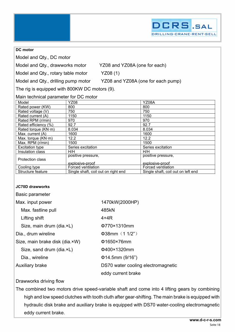
DC motor
Model and Qty., DC motor
Model and Qty., drawworks motor YZ08 and YZ08A (one for each)
Model and Qty., rotary table motor YZ08 (1)
Model and Qty., drilling pump motor YZ08 and YZ08A (one for each pump)
The rig is equipped with 800KW DC motors (9).
Main technical parameter for DC motorModel YZ08 YZ08ARated power (KW) 800 800Rated voltage (V) 750 750Rated current (A) 1150 1150Rated RPM (r/min) 970 970Rated efficiency (%) 92.7 92.7Rated torque (KN·m) 8.034 8.034Max. current (A) 1600 1600Max. torque (KN·m) 12.2 12.2Max. RPM (r/min) 1500 1500Excitation type Series excitation Series excitationInsulation class H/H H/H
Protection classpositive pressure,
explosive-proof
positive pressure,
explosive-proofCooling type Forced ventilation Forced ventilationStructure feature Single shaft, coil out on right end Single shaft, coil out on left end
JC70D drawworks
Basic parameter
Max. input power 1470kW(2000HP)
Max. fastline pull 485kN
Lifting shift 4+4R
Size, main drum (dia.×L) Φ770×1310mm
Dia., drum wireline Φ38mm(1 1/2”)
Size, main brake disk (dia.×W) Φ1650×76mm
Size, sand drum (dia.×L) Φ400×1320mm
Dia., wireline Φ14.5mm (9/16”)
Auxiliary brake DS70 water cooling electromagnetic
eddy current brake
Drawworks driving flow
The combined two motors drive speed-variable shaft and come into 4 lifting gears by combining
high and low speed clutches with tooth cluth after gear-shifting. The main brake is equipped with
hydraulic disk brake and auxiliary brake is equipped with DS70 water-cooling electromagnetic
eddy current brake.
www.d-c-r-s.comSeite 19
Structure and technical requirements
Double drum drawworks is with integral groove.
Main drum brake is equipped with hydraulic disk brake and electromagnetic eddy current brake. C/
double brake disk, safety and working caliper.
The drawworks consists of input shaft, drive shaft, sand drum shaft, drum shaft, etc.
Two YZ08/YZ08A motors are combined through input shaft of power unit. The two gears come
from 2 rows of chains between input shaft and drive shaft after power concourse, and another
2 gears come from 2 rows of chains between drive shaft and drum shaft. Thus the drawworks
has total 2×2 gears.
Mechanical shift is used on power input shaft and drive shaft. Clutch is used on drive shaft and
drum to shift.
All the controls (such as electrical, air and hydraulic) of drawworks are centralized in the driller’s
room.
Overwinding valve and digital crown saver system is equipped on the drawworks.
Main drum, sand drum, hydraulic disk brake and eddy current brake are installed on one
transportation skid. The motor and drive shaft are installed on one transportation skid.
Auto-driller
Equipped with hydraulic disk brake for auto-drilling.Hydraulic disk brake
Structure
Hydraulic disk brake is the compound unit with normal open working caliper and normal close safety
caliper, equipped with double brake disks. Adjustable cylinder is equipped on the safety caliper,
which can adjust the brake clearance, improve the using efficiency of brake block, prolong the
change cycle and make the install, dismantle and maintain safe and convenient. The floating
cylinder is equipped on the brake caliper, which has the function of auto-compensation. Double
oil source & double return passage & accumulator is equipped for the hydraulic system with
the feature of multi-protection.
The wear resistant treatment shall be performed on the regular connecting position between
brake disk and brake block. Forced wind cooling system is equipped on the brake disk of
drawworks.
Function
Operation brake: It can control the positive pressure of brake disk through operating the control
handle of the brake valve in order to provide the adjustable brake moment, which can realize
the bit feed, WOB adjustment, trip in/out speed, etc.

www.d-c-r-s.comSeite 20
Emergency brake: Press the red emergency brake button in the emergency. Therefore the operation
caliper and safety caliper can brake in emergency.
Parking brake: Pull down the parking brake handle and the safety caliper brakes to prevent the
hook slipping & falling while the rig stops operation or the driller leaves the driller’s console.
Over-winding protection: While the traveling block rises in the certain position, the overwinding
valve can reverse automatically to realize the emergency brake in order to prevent the traveling
block colliding with crown due to the false operation or any other reasons.
Electric driving control system
System scheme
1) The power of system adopts four 1365kVA 600V 50Hz diesel generating sets. The control
system of generator can realize stability of frequency and voltage, net operation and load
assign homogeneously. Output 600V is powered to DC speed adjustment cabinet and supplied
power to MCC and life electric devices through one 1500kVA 600V/400V 50Hz transformer.
2) The system is equipped with digital control speed regulation device. "The one-to-one” controls
motors of drawworks, rotary table, mud pump and auto-driller to realize stepless speed
regulating and satisfy the driving requirements. The drawworks adopts 800kW high speed DC
motors (2) and auto-driller adopts 45KW VFD motor (1), which can meet the requirements in
emergency.
3) MCC system can perform power distribution for rig 1500kVA 600/400V dry-type transformer
feeding and AC auxiliary machinery, illumination system, etc. The transformer input side is
equipped with 600V 1600A 3Φ 50Hz breaker. Transformer output side is equipped with 400V
2000A 3Φ 50Hz breaker. The auxiliary generator sets is equipped with 400V 600A 3Φ 50Hz
breaker. Breaker at the output side of transformer and breaker of auxiliary generating sets
interlock to supply power supply to MCC. The interface of industry electric network electric drive
rig and 600V 4000A 3Φ 50Hz breaker (its incoming line is industry electric network interface
and its outgoing line connects AC bus row of electric control room) are equipped. The top drive
power supply 600V 1350A 3Φ 50Hz breaker are is equipped, and supply power source for
geological logging device (with small filter) and two 150A interfaces.
4) The system is equipped with SCR houses (2). Its arrangement is reasonable and its installation
is reliable. The overall dimensions can be controlled within 12600 (L) × 2900 (W) × 3050 (H)
5) The system adopts 8MF standard switch cabinet which can supply power, control and protect
the standard electric system of well site. Each cabinet has the function of ground protection
and each control unit has repair lock function. It adopts intelligent soft start device and PLC
control to improve its reliability.

www.d-c-r-s.comSeite 21
6) The automatic feeding system of main motor can control drilling speed and bit pressure of rig to
realize constant bit pressure automatic feeding within the speed of 0.1-36m/h, modify the set
parameters, monitor parameters of bit pressure, drilling speed, position of traveling block, auto-
control reducing of traveling block and stop, emergency brake in order to prevent drilling string
not well braked, drilling pipe sticking and increase drilling speed and drilling ahead quality.
7) The control system of rig adopts high performance PLC as control centre (use double PLC system
and equip with bypass system. When the double PLC system fails, use the bypass system as
emergency operation). The digital devices shall be made up network through site main wire
control techniques to realize high speed communication among control systems of generator
control unit, speed regulating units (9), intelligent remote control driller’s monitoring, electric,
air and hydraulic control, human-machine interface, automatic feeding, integrated instrument
system, electronic protective device, etc; real time monitoring of upper industry control
machine; store running status of each system and supply trouble diagnostic reports. The upper
industry control machine IPC, automatic grade (PLC), touch screen of driller’s operation stand
pass DeviceNet network connection and PLC, remote-control I/O of driller’s house, I/O rack
pass ControlNet connection, which make up of three-grade network system, which can realize
parameters bidirectional transmission, integrated drilling instrument parameters and display,
all kinds of status presentation and help text display. It can set up a digital, information and
intelligent management platform that will realize remote data transmission, trouble monitoring,
optimizing control and monitoring the whole drilling process. The operation and monitoring of
system has two modes: PLC normal mode and relay emergency mode.
8) The integrated remote control driller’s operation station has functions of rig operation, drilling
parameters real time display, electric system monitoring and display, trouble display and
warning.

www.d-c-r-s.comSeite 22
Unitized equipmentControl cabinet of diesel generator 4 Synchronization system and power supply cabinet 1 6RA70 DC speed adjustment cabinet (drawworks) 2 6RA70 DC speed adjustment cabinet (rotary table) 1 6RA70 DC speed adjustment cabinet (mud pump) 6 EtherNet、ControlNet、DeviceNet main wire
system1 for each
Power, control cables and splicing of complete set
of DC motors1
Complete set of power, control cable, splicing
piece, bus of SCR house1
Over-pressure protection unit 2MCC cabinet (switch cabinet) 1Combination control cabinet (w/ IPC, PLC, HMI, I/O
plate)1
Speed adjustment handle 1
Intelligent remote-control driller’s operation system
(incl. PLC, HMI)
Screen and
touch screen
are 15″LCD
screen
1
Communication board, expansion board 1, 2 1
Sensor
Drawworks
Motor(2), drum
shaft (1)
3
Auto-driller control system w/independent motor 1Earthing device 1Position auto-control system of traveling block 1Integrated instrument system 1SCR electrical control house (incl. 1500KVA
transformer, air conditioner)2
Repair tools includes: oscilloscope (1), multimeter
(1), ammeter (1), megger (1), hand tools for
electrician (1), phase sequence meter (1),
photoelectricity tachometer (1), infrared
thermometer (1)
1
Main technical parameters of transducer Purpose Motor, drawworks Motor, rotary table Motor, mud pumpRated input voltage (V) 3AC 600 3AC 600 3AC 600Rated input current (A) 946 946 946Rated output voltage (V) 3AC 0~750V 3AC 0~750V 3AC 0~750VRated output current (A) 950 950 950Max. output current (A) 1750 60S 1750 60S 1750 60SLight load current (A) 783 783 783Rated power (kW) 800 800 800Overall dimension
(W×H×D)2100×2000×600 2100×2000×600 2700×2000×600
Flow rate, cooling air
(m3/s)1.45 1.45 1.45
Noise db(A) 85 85 85Protection class IP20 IP20 IP20

www.d-c-r-s.comSeite 23
Hydraulic power unit (HPU)
It consists of base buffer unit, disk brake, mechanical tools on wellhead, reel, etc.
Technical parameters
System rated flow 120L/Min
System rated pressure 16MPa /25MPa
Motor power 37kW
Effective volume, oil tank 1000L
System oil filtering accuracy 30μm
Power, electrical heater 2×3kW
Overall dimension (max.) 600×1600×1600mm
Technical performances
The working pressures of HPU are 25MPa and 16MPa.
The HPU consists of hydraulic system of mechanical tools on wellhead, hydraulic system of disk
brake, hydraulic system of casing stabbing board, oiling system, heating & cooling system, oil
tank, electrical-control cabinet, instrument, indicator, etc.
Oil tank is placed on the top and pump assy, is placed below. It is equipped with 37KW plunger
pump (1), 5.5KW hydraulic pump of casing stabbing board (1), 0.75KW oil-filling pump (1),
2.2KW hydraulic pumps of disk brake (2), 3KW heaters (2) and 0.75KW wind-cooling unit (1).
Oil tank is fully sealed. The hydraulic valves are imported. Oil lines are equipped with self-
sealing quick connector. It is equipped with electrical oil filling & filtering unit, which has the
function of oiling and filtering oil in the oil tank. It is equipped with explosive-proof electrical
equipments, which can heat the oil in winter and cool in summer. It is equipped with explosive-
proof integration electrical-control cabinet with the function of startup & shutdown of motors
and heater and alarm & display the oil temperature, oil level and oil stain. Driller’s room
The electrical, air and hydraulic control & communication system are all centralized in the driller’s
room, which can monitor and control the rig for the driller. The explosive-proof, anti-corrosive,
shock resistent, heat insulative, noise insulative protections are equipped in the driller’s room
to meet the requirements of drilling conditions.

www.d-c-r-s.comSeite 24
The disk brake control, pneumatic operation, electrical driving control & touch screen, parameter
indicator, hydraulic operation system, control box for top drive (installation position is reserved),
auto-driller, touch screen for controlling the traveling block, communication system, ect. are
equipped in the driller’s room to form the integrated and intelligent control console. The driller
can process the air control, hydraulic control, electrical drive, drilling parameters, auto-driller,
etc. centrally via PLC on control console, which can control and display the electrical, air,
hydraulic and drilling parameters.
The overall dimension of driller’s rooms is 3000×2400×2500mm (it carried out based on SY 5576-
93 field camp standard of drilling crew) with the stainless steel surface, which is featured with
nice appearance, good structural strength and hoisting rigidity. The driller’s room is installed in
the derrick A-frame on the left side of substructure with shock resistance connection between
driller’s room and substructure. One door is equipped on the left side of driller’s room. The
tempered glass with glue is installed on the driller’s room near the rotary table side to observe
the substructure conveniently. The roof on the driller’s room is inclined and 1 tempered glass
with glue is installed w/protection net. The control stand of drawworls motor is on the right
side of driller’s seat equipped with microphone, horn button and operation handle of hydraulic
cathead. 2 sets of 15” explosive-proof LCD screen are equipped on the operation stand
separately. The left side is display screen of drilling parameters and right side is electrical-
controlled touch screen. The mechanical weight indicator (1) and pump pressure gauge (1) are
installed in front of the driller. The operation stand of top drive is installed between the front of
driller’s seat and walls on top of weight indicator. Dry power fire extinguishers (2) are equipped
in the driller’s room. The anti-static electricity rubber is placed on the floor in the driller’s room.
Explosive-proof horn is installed on the roof. Smoke alarming unit is equipped.
The inner arrangement of driller’s room shall be with the feature of observing, operating, checking
and maintaining conveniently and with good heat preservation and strong durability, which can
meet the HSE requirements, etc.
The display screen of instrument: The parameters are displayed in the left side and the working
condition & operation of power machine is on the right side. The working condition shall be
shifted into: tripping in (incl. connecting single piece, redressing for single piece), tripping in/
out, redressing (long-distance redressing), case running, auxiliary works (mud circulation, etc.).
It can be connected with the interface of mud volume (recharging amount, returning amount,
total recharging amount; mud amount for single tank and increasing amount; total mud amount
and increasing amount).
www.d-c-r-s.comSeite 25
Two kinds of instrument panel, that is the unit is metric system while displaying Chinese and the unit
is British system while displaying English. Anti-static electricity is equipped on the screen.
The analogous dial and digital display dial are equipped on the instrument, which can display
various parameters, such as total weight, WOB, standpipe pressure, outlet displacement,
stroke (incl. accumulative value), torque of rotary table, RPM of rotary table, hook speed, bit
feeding speed, makeup & breakout torque of cathead, height of traveling block, well depth,
drilling time, mud fluid level, mud volumn, etc. The sensors can meet the relevant explosive-
proof requirement
The monitoring system consists of cam system, displaying system and control system. The
monitoring system can store the video for 8hours. The cam system consists of 5 cams, among
which the drum, crown and shale shaker is fixed-type, racking board and mud pump is rotating-
type. The weatherproof guard is equipped on the cam cover with good sealing performance,
w/antifogging device and can meet the explosive-proof requirements. One 15” LCD monitor is
equipped and installed in the driller’s room in the same of parameter display screen, the angle
can be adjusted based on the habbit of driller. 5 pictures can be displayed on the monitor and
any other picture-combination can be shifted and displayed.Air source and purifying device for air source
Basic parameter
Compressor unit
Model LS12-50HH screw-type compressor
sets (USA SULLAIR)
Air displacement 5.5 m3/min
Exhaust pressure 1MPa
Cooling type air cooling
Matched motor 37kW/380V
Volume, air tank 2×1.5m3+×2.5m3
Cold-starting air compressor electrical/manual-type
(air displacement 0.6m3/min)
Configuration and technical requirements
The air source and decontamination device for air source mainly consists of: 2 sets of electric screw
compressor unit (including automatic switching cabinet), 1 set of freezing type dryer, 1 set of
2.5m3 air reservoir, 2 sets of 1.5m3 air reservoir (base position), 1 set of electrical/manual (air
displacement 0.6m3/min) cold-starting air compressor and complete set of pipelines, valves
etc.

www.d-c-r-s.comSeite 26
Safety valve, pressure gauge and blow-off valve are installed on air reservoir, convenient for
operation.The air reservoir tank uses the same generator house together with auxiliary
generator.
The flow chart of air source system is designed as following: compressor—dryer—air reservoir—
air system pipelines for drilling rig.
Air supply system
It is composed of 2.5m3 air reservoir (1), 1.5m3 air reservoir (2), pipe groove, air supply line and
complete set of valves etc.
The pipeline control valves use stainless steel ball valve, c/w bypass line for inspecting dryer. The
main air pipeline is 2”. The safety valve outlet of air bottle should be installed under the floor
of generator house.
The rated working pressure of air reservoir is 1MPa, complete with safety valve, check valve,
drainage valve and air pressure gauge. Connecting pipelines are made of galvanized steel
pipes (transitional parts are pressure hoses). The platform is installed on mounting position,
convenient for inspection and maintenance.
Pipe groove consists of oil, water and air supply pipe groove, cable groove of foldable substructure,
brake cooling manifold of drawworks, etc.Substructure (as per API Spec 4F)
Basic parameter
Height, drill floor 10.5m
Clear height, rotary beam 9.0m
Area, substructure ≥132m2(11.27m×12m)
Max. static load, rotary beam 4500kN
Rated load, setback 2200kN
Capacity, setback (114mmDP, 28msetback) 7000m
10”DC 4strings, 8”DC 6strings
Structure and accessories
The substructure is with rotation & raising structure. The lowest height is 3m.
C/ cushion cylinders (2) for raising and lowering the substructure.
C/ ramp (1set, corrugation-type), emergent slide (1set), tong backup posts (2) and ladders (3sets,
one is on right side, one is at the rear and one is in the front).
C/ fixed position for 5t hydraulic winches (2)
Adjustable backup tong post (2), hydraulic backup tong post (1)

www.d-c-r-s.comSeite 27
The width of ladder is 800mm w/double handrails. Overlapping position of ladder and drill floor
shall be equipped with safety pin. Ladder inlet shall be equipped with safety chain. The ladder
pedals are made of flat bar.
Guide rail (for hoisting wellhead device) and 40T BOP handling unit (hydraulic driven) are installed
under substructure.
Technical parameter of BOP handling unit
Max. lifting load 2×200=400kN
Max. lifting travel 4m
Max. lifting speed (double sides) 3.39m/min
Max. lifting speed (single sides) 6.78m/min
Max. lowering speed (double side) 6.51m/min
Max. lowering speed (single side) 13.02m/min
Max. travelling speed (double sides, double directions) 12m/min
Max. working pressure, hydraulic system 16MPa
Max. flow rate, hydraulic system 120L/min
Dia, wireline Ø28mm
Two DP protective stands are installed outside the ramp door, DP buckle connecting. The height
of stand is 1.8m.
Chain guard should be installed when the length between handrails is over 0.2m. The posts on two
sides of door ramp are equipped with 3 chain guards, and the escape slideway is equipped
with 1 chain guards.
Parallel with the rig floor (including rotary table, setback). Rotary table is equipped with anti-slip
pad. Diamond plate is placed on the drill floor. The clearance of each floor plate should be less
than 15mm.
C/ 1.5m3 air tanks (2).
All the hydraulic and air pipelines are installed inside, c/w guard cover.
Mud collecting tank is installed under drill floor, with the purpose of centralized recycling the soil on
the drill floor such as sewage etc. without falling onto the ground.
The substructure is marked with “left” and “right”.
The drill floor shall be flat, convenient for workers to escape.
C/ kick back roller.

www.d-c-r-s.comSeite 28
The front subbase handrail is made of 80mm×80mm×6mm square steel tube and rear subbase
handrail is made of 50mm×50mm×4mm square steel tube. The handrail height is 1.2m. Toe
board height is 250mm (distance to drill floor is 3~5mm). The handrail is fixed by latch pin and
made permanent installation mark.
It is equipped with manual drum on the substructure, which is used for cleaning rubber hose
Accurate benchmark is installed on the wellhead position of substructure pedestal.
The substructure is marked with API emblem.

www.d-c-r-s.comSeite 29

www.d-c-r-s.comSeite 30

www.d-c-r-s.comSeite 31
www.d-c-r-s.comSeite 32

www.d-c-r-s.comSeite 33

www.d-c-r-s.comSeite 34

www.d-c-r-s.comSeite 35
www.d-c-r-s.comSeite 36

www.d-c-r-s.comSeite 37
www.d-c-r-s.comSeite 38

www.d-c-r-s.comSeite 39
www.d-c-r-s.comSeite 40

www.d-c-r-s.comSeite 41

www.d-c-r-s.comSeite 42

www.d-c-r-s.comSeite 43

www.d-c-r-s.comSeite 44

www.d-c-r-s.comSeite 45

www.d-c-r-s.comSeite 46

www.d-c-r-s.comSeite 47

www.d-c-r-s.comSeite 48

www.d-c-r-s.comSeite 49

www.d-c-r-s.comSeite 50

www.d-c-r-s.comSeite 51

www.d-c-r-s.comSeite 52

www.d-c-r-s.comSeite 53

www.d-c-r-s.comSeite 54

www.d-c-r-s.comSeite 55

www.d-c-r-s.comSeite 56

www.d-c-r-s.comSeite 57

www.d-c-r-s.comSeite 58

www.d-c-r-s.comSeite 59

www.d-c-r-s.comSeite 60

www.d-c-r-s.comSeite 61

www.d-c-r-s.comSeite 62

www.d-c-r-s.comSeite 63

www.d-c-r-s.comSeite 64

www.d-c-r-s.comSeite 65

www.d-c-r-s.comSeite 66

www.d-c-r-s.comSeite 67

www.d-c-r-s.comSeite 68

www.d-c-r-s.comSeite 69

www.d-c-r-s.comSeite 70

www.d-c-r-s.comSeite 71

www.d-c-r-s.comSeite 72

www.d-c-r-s.comSeite 73

www.d-c-r-s.comSeite 74

www.d-c-r-s.comSeite 75

www.d-c-r-s.comSeite 76

www.d-c-r-s.comSeite 77

www.d-c-r-s.comSeite 78

www.d-c-r-s.comSeite 79

www.d-c-r-s.comSeite 80
Petroleum Custom SolutionsEngineered for All Your Petroleum Needs