BEIJING HUADE RE 22277/12.2004 with hand lever Type WMM ... · toNS toNR toOR to25 for symbol Q, 6%...
12
RV HUADE HYDRAULICS Cartridge throttle Type 4WMM6 Features: - Direct actuated directional spool valve with hand lever - With spring return or detent, optional - For subplate mounting - Porting pattern to Din 24 340 form A, ISO 4401 and CETOP-RP 121H Function, section 4/3 and 4/2 directional control valves with hand leverType WMM Size up to35MPa up to 450L/min 610 16 25 The type WMM valves are hand lever actuated directional spool valves.They control the start, stop and direction of a flow. The directional valves basically comprise of a housing (1), hand lever(2), control pool (3), as well as one or two return springs (4).In the unoperated condition the control spool (3) is held in the neutral or its initial position by the return springs (4). The control spool(3) is actuated via the hand lever (2), this acts via a joint and the pin(5) directly onto the control spool (3). The spool is thereby moved out of its rest postion into its required switched position.After the hand lever (2) has been returned to the switched position zero, the spool (3) is returned to the neutral position via the return springs (4). Type H-4WMM../F.. (with detent) These valves are either 2 or 3 position directional control valves which are fitted with a detent (6), which operates in all of the switched positions. RE 22277/12.2004 Replaces RE 22275/05.2001 BEIJING HUADE HYDRAULIC INDUSTRIAL GROUP CO.,LTD.
-
Upload
nguyenhanh -
Category
Documents
-
view
219 -
download
0
Transcript of BEIJING HUADE RE 22277/12.2004 with hand lever Type WMM ... · toNS toNR toOR to25 for symbol Q, 6%...

� RV� HUADE HYDRAULICS
Cartridge throttle
Type 4WMM6
Features:
- Direct actuated directional spool valve
with hand lever
- With spring return or detent, optional
- For subplate mounting
- Porting pattern to Din 24 340 form A, ISO 4401
and CETOP-RP 121H
Function, section
4/3 and 4/2 directional control valves
with hand lever�Type WMM
Size up to35MPa up to 450L/min 6� 10�
16 �25
The type WMM valves are hand lever actuated directional spool valves.They control the start, stop and
direction of a flow.
The directional valves basically comprise of a housing (1), hand lever(2), control pool (3), as well as one or
two return springs (4).In the unoperated condition the control spool (3) is held in the neutral or its initial
position by the return springs (4). The control spool(3) is actuated via the hand lever (2), this acts via a joint
and the pin(5) directly onto the control spool (3). The spool is thereby moved out of its rest postion into its
required switched position.After the hand lever (2) has been returned to the switched position zero, the spool
(3) is returned to the neutral position via the return springs (4).
Type H-4WMM../F.. (with detent)
These valves are either 2 or 3 position directional control valves which are fitted with a detent (6), which
operates in all of the switched positions.
RE 22277/12.2004
Replaces�
RE 22275/05.2001
BEIJING HUADE
HYDRAULIC INDUSTRIAL
GROUP CO.,LTD.

� SM�HUADE HYDRAULICS
Ordering details
35MPa (Only Size 16�25)
Size 6 = 6
Size 10 = 10
Size 16 = 16
Size 25 = 25
Further etails in clear text
No code = Mineral oils V = Phospate ester
G WM B
Only for Size 6 and 10
No code = Without throttle insert
B08 = Throttle � 0.8 mm
B10 = Throttle � 1.0 mm
B12 = Throttle � 1.2 mm
Note:Size16.25 without throttle
No code = Without detent
F = With detent
50 = Series 50 (50 to 59: unchanged installation and connection
dimensions)�For Size 6�16�25�
10 = Series 10(10 to 19: unchanged installation and connection
dimensions) �For Size 10�
B = Technology of Beijing Huade Hydraulic
H-
Example:Spool E on side"a".
Order example:...EA...
Spool E on side"b".
Order example:...EB...
1�Spool E1�P �A/B�preview port�only for
Size 6�.
2� For Size 10,Spool B�Y�hand lever on side B.
3�Spool A and B only for Size 6 and 10.
4�Spool K and Z only for Size16 and 25.
5�Spool S only for Size16.
6�For Size16 and 25,spool C is the same
as spool H .
For Size16 and 25,spool D is the same
as spool E.
7�Only for Size16 and 25.
8�Only for Size16 and 25.
3 service ports ��
4 service ports ��

� SN� HUADE HYDRAULICS
Technical data ( For applications outside these parameters, please consult us! )
Size
Maximum port A�B�P
Working pressure port T
(MPa)
(MPa)
Maximum fluid
Fiow cross section
�control position 0�
Pressure fluid
Control power of push lever �N�
Fluid temperature range (�)
Viscosity range (mm2/s)
Weight (Kg)
�L/min�
6 10 16 25
to31.5 to35
toNS toNR toOR to25
to60 to100 to300 to450
for symbol Q, 6% of nominal cross section
for symbol W, 3% of nominal cross section
for symbol Q�V,16% of nominal cross section
for symbol W, 3% of nominal cross section
Mineral oil or Phospate ester
-30�� 80
2.8�� 500
approx.1.4 approx3.3 approx8 approx17
Wi thou t r e tu rn p ressu reapprox20Wi thou t r e tu rn p ressu reapprox30
with detent approx.16~23 without detent approx. 20~27
approx120
Spool
Shifted position
P �A P �B A � T B � T
A 3 3 - -
B 3 3 - -C 1 1 3 1D 5 5 3 3E 3 3 1 1F 1 3 1 1G 6 6 9 9H 2 4 2 2J 1 1 2 1L 3 3 4 9M 2 4 3 3P 3 1 1 1Q 1 1 2 1R 5 5 4 1T 10 10 9 9U 3 3 9 4V 1 2 1 1W 1 1 2 2Y 5 5 3 3
Characteristic curves:
Flow in L/min
Characteristic curves (measured at � = 41 mm 2 /s and t = 50 �)
Pre
ssur
e di
ffere
nce
in M
Pa
7 Spool "R" at controller position A to B
8 Spool "G" and "T"at middle position P to T
approx75
Type WMM6

� SO�HUADE HYDRAULICS
Characteristic curves: Type WMM10
4 Spool "G" and "T" at middle position P to T
7 Spool "R" at switch position A to B
Pre
ssur
e di
ffere
nce
in M
Pa
Pre
ssur
e di
ffere
nce
in M
Pa
Flow in L/min
Flow in L/min
Characteristic curves: Type WMM16
6 Spool "G" and "T" at middle position P to T
8 Spool "S" at middle position P to T
Spool Shifted position
�� A ��B A � T B � T
== E�D�Y 1 1 1 3
F 2 2 3 3G�T 5 1 3 7
H�C�Q 2 2 3 3V�Z 2 2 3 3
J�K�L 1 1 3 3M�W 2 2 4 -
R 2 2 4 -U 1 1 4 7S 4 4 4 -
SpoolShifted position
P � A P �B A � T B� T
A 2 2 - -B 2 2 - -C 2 2 3 3D 2 2 3 3E 2 2 4 4F 2 3 3 5G 3 3 4 6H 1 1 4 5J 2 2 3 3L 2 2 3 5M 1 1 5 5P 3 2 5 3Q 2 2 4 4R 2 4 3 -T 3 5 5 6U 2 2 3 5V 2 2 5 5W 2 2 5 5Y 2 2 5 3
� SP� HUADE HYDRAULICS
SpoolShifted position
P � A P �B A� T B � T
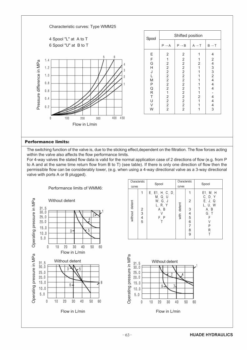
E 2 2 1 4F 1 2 1 2G 2 2 2 4H 2 2 1 3J 2 2 1 3L 2 2 1 2M 2 2 1 4P 2 2 1 4Q 2 2 1 4R 1 2 1 -T 2 2 2 4U 2 2 1 4V 2 2 1 4W 2 2 1 3
Performance limits:
Characteristic
curvesSpool
Characteristic
curvesSpool
with
det
ent
1
2345
E�E1�H�C�D�M�Q�UW�G�JL�R�Y
A�BV
F�PT
1
2
3456789
E1�M�HC�D�YE�J�QL�U�W
A�BG�T
FVPRT
Characteristic curves: Type WMM25
4 Spool "L" at A to T
6 Spool "U" at B to T
Flow in L/min
The switching function of the valve is, due to the sticking effect,dependent on the filtration. The flow forces actingwithin the valve also affects the flow performance limits.For 4-way valves the stated flow data is valid for the normal application case of 2 directions of flow (e.g. from Pto A and at the same time return flow from B to T) (see table). If there is only one direction of flow then thepermissible flow can be considerably lower, (e.g. when using a 4-way directional valve as a 3-way directionalvalve with ports A or B plugged).
Performance limits of WMM6:
Without detent
Flow in L/min
Flow in L/min Flow in L/min
Without detent
Ope
ratin
g pr
essu
re in
MP
aO
pera
ting
pres
sure
in M
Pa
Ope
ratin
g pr
essu
re in
MP
a
Pre
ssur
e di
ffere
nce
in M
Pa
Without detent
with
out
dete
nt

� SQ�HUADE HYDRAULICS
Characteristic curves: Type WMM10
Characteristiccurves:
Spool
1
2
3
4
5
A�B
H
F�G�P�R�T
J�L�Q�U�W
C�D�E�M�V�Y
2-position valves , without detent
flow q V in L/min
Spool
C
D
K
Z
3-position valves without detent
flow q V in L/min
Spool
E�H�J�L�M
Q�R�U�W
F�P
G�S�T
V
7 14 21 28 35
300 300 300 260 220
300 300 210 190 160
300 300 200 150 130
300 240 190 170 150
7 14 21 28 35
300 300 210 190 170
300 300 220 210 180
300 260 200 180 170
300 300 300 300 300
2-position valves , with detent
flow q V in L/min
Spool
= C�D�K�Z
3-position valves with detent
7 14 21 28 35
300 300 300 300 300
Ope
ratin
g pr
essu
re in
MP
a
Flow in L/minCharacteristic curves: Type WMM16
flow q V in L/min
Spool
E�H�J�L�MQ�R�U�W
F�P
G�T�S
7 14 21 28 35
300 300 280 230 230
300 300 230 230 230
300 300 250 230 230
300 300 300 300 300
V
2-position valves without detent
flow q V in L/min
Spool
C
D
K
Z
3-position valves without detent
flow q V in L/min
Spool
E�J�L�MQ�R�U�W
F
G�T
H
7 14 21 28 35
450 300 250 200 180
350 300 275 250 200
200 150 140 130 120
300 270 240 220 200
7 14 21 28 35
450 250 200 135 110
450 330 290 230 180
450 450 400 400 350
450 310 240 215 150
450 310 280 270 200
450 450 450 450 450
P
V
2-position valves with detent
flow q V in L/min Operating pressure max(MPa)
Spool
C�D�K�Z
7 14 21 28 35
450 450 450 450 450
3-position valves with detent
flow q V in L/min
Spool 7 14 21 28 35
450 450 450 450 450
E�F�G�H�JL�M�P�R�TU�W
V 450 450 400 350 300
Characteristic curves: Type WMM25
=Operating pressure max(MPa)
Operating pressure max(MPa)
=Operating pressure max(MPa)
=Operating pressure max(MPa)
=Operating pressure max(MPa)
=Operating pressure max(MPa)
=Operating pressure max(MPa)
� SR� HUADE HYDRAULICS
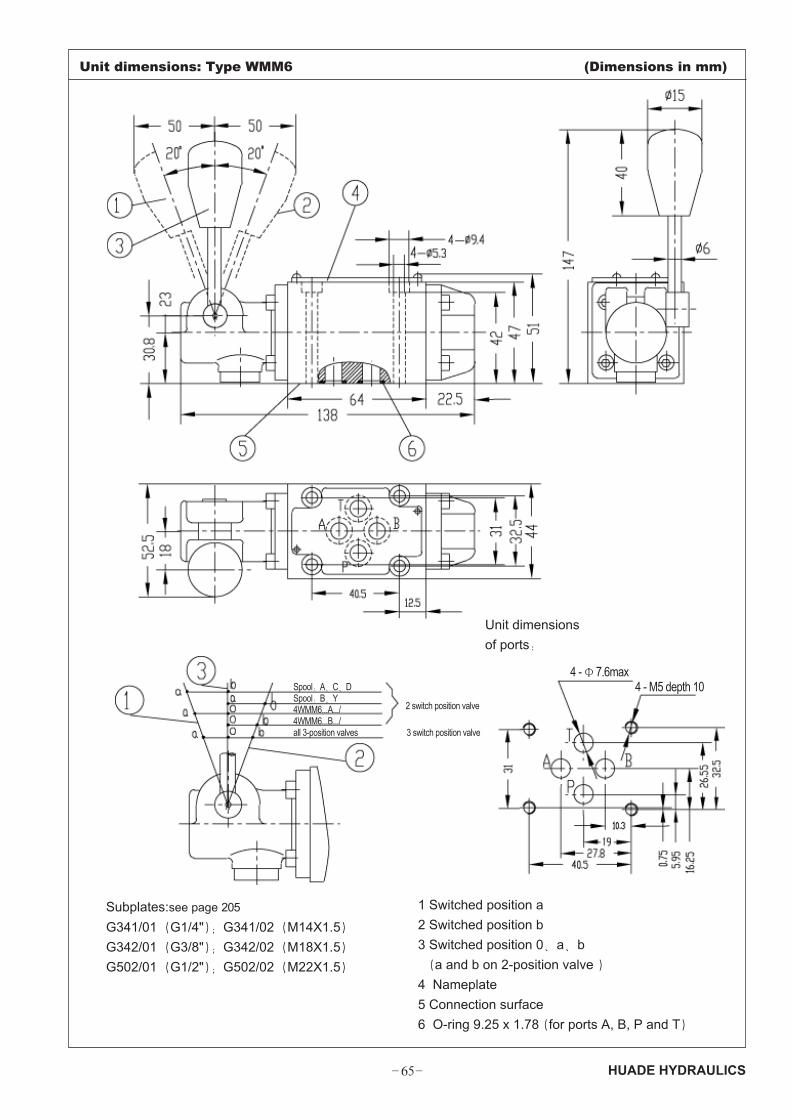
Unit dimensions: Type WMM6 (Dimensions in mm)
Subplates:see page 205
G341/01�G1/4"��G341/02�M14X1.5�
G342/01�G3/8"��G342/02�M18X1.5�
G502/01�G1/2"��G502/02�M22X1.5�
Unit dimensions
of ports�
1 Switched position a
2 Switched position b
3 Switched position 0�a�b
�a and b on 2-position valve �
4 Nameplate
5 Connection surface
6 O-ring 9.25 x 1.78�for ports A, B, P and T�
Spool�A�C�DSpool�B�Y
2 switch position valve4WMM6...A.../4WMM6...B.../all 3-position valves 3 switch position valve
4 -�7.6max 4 - M5 depth 10

� SS�HUADE HYDRAULICS
Unit dimensions: Type WMM10(with detent ) (Dimensions in mm)
Subplates: see page 206
G66/01�G3/8"�� G66/02�M18X1.5�G67/01�G1/2"�� G67/02�M22X1.5�G534/01�G3/4"�� G534/02�M27X2�
1 Switched position a2 Switched position b3 Switched position 0�a�b �a and b on 2-position valve �
2-way valve,the hand lever of
spool B�Y on side port B
4 Nameplate5 Connection surface6 O-ring 12 x 2(for ports A, B, P and T)7 When using control piece,may regarded as
assistant return port
Spool�A�C�D�EA...
Spool�EB...
all 3-position valves
2 switch position valve
4- � 10.5
Unit dimensions of ports�

� ST� HUADE HYDRAULICS
Unit dimensions: Type WMM10(without detent ) (Dimensions in mm)
1 Switched position a
2 Switched position b
3 Switched position 0�a�b
�a and b on 2-position valve �
4 Nameplate
5 Connection surface
6 O-ring 12 x 2(for ports A, B, P and T)
7 When using control piece,may regarded as
assistant return port
The other Unit dimensions
see "with detent"
2-way valve,the hand
lever of spool B�
Y on side port B
Spool�A�C�D�EA...
Spool�EB...
all 3-position valves
2 switch position valve

� SU�HUADE HYDRAULICS
Unit dimensions: Type WMM16 (Dimensions in mm)
Unit dimensions of ports�
ball 40approx.230
Spool 4WMM16...B.../
Spool 4WMM16...A.../
Spool C�D�K�Z�Y
all 3-position valves
Subplates (see page207�208)
G172/01�G172/02
G174/01�G174/02
G174/08
1 Switched position a
2 Switched position b
3 Switched position 0�a and b on 2-position valve �
4 2-position valve and 3-position valves , with detent. 3-position valve, spring-centred5 2-position valve�without detent6 Nameplate7 O-ring 22 x 2.5�For ports A, B, P and T�
O-ring 10 x 2 �For ports X �Yand L�

� SV� HUADE HYDRAULICS
Unit dimensions: Type WMM25 (Dimensions in mm)
Subplates (see page 209)G151/01�G1"��G151/02�M33X2�G153/01�G1"��G153/02�M33X2�G154/01�G1 1/4"��G154/02�M42X2�G156/01�G1 1/2"��G156/02�M48X2�G153 only used on valves which are pressure-centred
1 Switched position a2 Switched position b3 Switched position 0�a and b on 2-position valve �4 2-position valve and 3-position valve with detent� 3-position valve, spring-centred5 2-position valve�without detent6 Nameplate7 O-ring 27 x 3�for ports A, B, P and T�
O-ring 19 x 3 �for ports X �Yand L�
Required surface finish of
mating piece
approx.320
2-position valve�spool...B.../�
2-position valve�spool...A.../�
2-position valve�spools C�D�K�Z�Y�
all 3-position valves
Unit dimensions
of ports�
depth
� TM�HUADE HYDRAULICS
Notice1. The fluid must be filtered. Minimum filter fineness is 20 µµµµµm.
2. The tank must be sealing up and an air filter must be installed on air entrance.
3. Products without subplate when leaving factory, if need them, please ordering specially.
4. Valve fixing screws must be high intensity level (class 10.9). Please select and use them
according to the parameter listed in the sample book.
5. Roughness of surface linked with the valve is required to .
6. Surface finish of mating piece is required to 0.01/100mm.
All rights reserved-Subject to revision