Behaviour of Tall Buildings using Tuned Mass Dampers
11
Behaviour of Tall Buildings using Tuned Mass Dampers Mirza Aamir Baig Department of Civil Engineering Al-Falah University, Dhauj Faridabad Abstract:- Incalculable elevated structure has been built everywhere on over the world and the number is expanding step by step. This isn't just because of worried over high thickness of populace in the urban communities, business zones and space sparing yet additionally to build up land marks. As the seismic burden following up on a structure is a component of oneself load of the structure these structures are made similarly light and adaptable which have moderately low common damping, and in this manner the structures become more vibration inclined under wind and tremor stacking. To guarantee the useful execution of tall structures, different plan adjustments are conceivable, extending from elective basic frameworks to the use of inactive and dynamic control gadgets. This paper presents an outline of cutting-edge measures to lessen basic reaction of tall structures, including a conversation of assistant damping gadgets for moderating the seismic tremor and wind-initiated movement of structures. To guarantee the useful execution of tall structures, different plan adjustments are conceivable, running from elective auxiliary frameworks to the use of aloof and dynamic control gadgets. Latent tuned mass damper (TMD) is broadly used to control auxiliary vibration under wind load yet its viability to lessen tremor-initiated vibration is a developing procedure. Here an investigative examination is proposed to contemplate the adequacy of TMD to decrease auxiliary vibration in Tall Buildings. For this examination a 60m tall structure having 15 stories with a square arrangement of 20x20m has been displayed. The viability of single TMD to lessen basic vibrations, is read for a variety of TMD mass proportion Keywords:- Structural Motions, Damping, Passive and Active control devices, TMD, AMD 1.1 INTRODUCTION Vibration might be brought about by natural powers following up on a structure, for example, wind or earthquakes, or by an apparently harmless vibration source causing reverberation that might be ruinous, terrible or basically badly arranged. The seismic waves will make structures influence and waver in different manners relying upon the recurrence and heading of ground movement, and the tallness and development of the structure. Seismic movement can cause extreme motions of the structure which may prompt even auxiliary disappointment. The power of wind against tall structures can make the head of high rises move significantly in excess of a meter. This movement can be through influencing or winding. Certain points of wind and streamlined properties of a structure can emphasize the development and cause movement infection in inhabitants and posture genuine functionality issues. To upgrade the useful execution of the structure against seismic and wind powers, an appropriate structure configuration is performed utilizing elective basic frameworks and by usage of different vibration control equipment. 1.2 TUNED MASS DAMPERS (TMDs) TMDs being used, ordinarily oil dampers, thick and viscoelastic dampers Normally, a TMD comprises of an inertial mass appended to the structure area with most extreme movement, by and large close to the top, through a spring and damping component, ordinarily gooey and viscoelastic dampers. The recurrence of the damper is tuned to a specific auxiliary recurrence so when that recurrence is energized, the damper will resound out of stage with the basic movement. Vitality is disseminated by the damper dormancy power following up on the structure. The adequacy of TMDs is dictated by their dynamic qualities, stroke and the measure of the additional mass. Extra damping presented by the framework is additionally reliant on the proportion of the damper mass to the powerful mass of the structure in the method of intrigue, commonly coming about in TMDs, which weigh 0.25-1.0% of the structure's weight in the major mode (normally around 33%). Regularly, dividing limitations won't license customary TMD designs, requiring the establishment of elective arrangements including multi-stage pendulums, modified pendulums, and frameworks with precisely guided slide tables, hydrostatic heading, and covered elastic direction. Curl springs or variable solidness pneumatic springs commonly give the firmness to the tuning of TMDs. In spite of the fact that TMDs are frequently viable, far superior reactions have been noted using different damper setups (MDCs) which comprise of a few dampers set in corresponding with appropriated characteristic frequencies around the control tuning recurrence (Kareem and Kline 1995). Table 1. Mass support mechanisms and dampers for TMDs Mass Supporting Mechanism Damper Attached to TMD Pendulum, including multiple type Oil Dampers Roller Bearings & Coil Springs Viscous Dampers Laminated Rubber Bearings Visco-Elastic Dampers International Journal of Engineering Research & Technology (IJERT) ISSN: 2278-0181 http://www.ijert.org IJERTV9IS090069 (This work is licensed under a Creative Commons Attribution 4.0 International License.) Published by : www.ijert.org Vol. 9 Issue 09, September-2020 84 Ubair Gul Khan Department of Civil Engineering Al-Falah University, Dhauj Faridabad
Transcript of Behaviour of Tall Buildings using Tuned Mass Dampers

Behaviour of Tall Buildings using Tuned Mass
Dampers
Mirza Aamir Baig Department of Civil Engineering
Al-Falah University, Dhauj Faridabad
Abstract:- Incalculable elevated structure has been built everywhere on over the world and the number is expanding step by step. This
isn't just because of worried over high thickness of populace in the urban communities, business zones and space sparing yet additionally
to build up land marks. As the seismic burden following up on a structure is a component of oneself load of the structure these structures
are made similarly light and adaptable which have moderately low common damping, and in this manner the structures become more
vibration inclined under wind and tremor stacking. To guarantee the useful execution of tall structures, different plan adjustments are
conceivable, extending from elective basic frameworks to the use of inactive and dynamic control gadgets. This paper presents an outline
of cutting-edge measures to lessen basic reaction of tall structures, including a conversation of assistant damping gadgets for moderating
the seismic tremor and wind-initiated movement of structures. To guarantee the useful execution of tall structures, different plan
adjustments are conceivable, running from elective auxiliary frameworks to the use of aloof and dynamic control gadgets. Latent tuned
mass damper (TMD) is broadly used to control auxiliary vibration under wind load yet its viability to lessen tremor-initiated vibration
is a developing procedure.
Here an investigative examination is proposed to contemplate the adequacy of TMD to decrease auxiliary vibration in Tall Buildings.
For this examination a 60m tall structure having 15 stories with a square arrangement of 20x20m has been displayed.
The viability of single TMD to lessen basic vibrations, is read for a variety of TMD mass proportion
Keywords:- Structural Motions, Damping, Passive and Active control devices, TMD, AMD
1.1 INTRODUCTION
Vibration might be brought about by natural powers following up on a structure, for example, wind or earthquakes, or by an
apparently harmless vibration source causing reverberation that might be ruinous, terrible or basically badly arranged. The seismic
waves will make structures influence and waver in different manners relying upon the recurrence and heading of ground
movement, and the tallness and development of the structure. Seismic movement can cause extreme motions of the structure
which may prompt even auxiliary disappointment. The power of wind against tall structures can make the head of high rises move
significantly in excess of a meter. This movement can be through influencing or winding. Certain points of wind and streamlined
properties of a structure can emphasize the development and cause movement infection in inhabitants and posture genuine
functionality issues. To upgrade the useful execution of the structure against seismic and wind powers, an appropriate structure
configuration is performed utilizing elective basic frameworks and by usage of different vibration control equipment.
1.2 TUNED MASS DAMPERS (TMDs)
TMDs being used, ordinarily oil dampers, thick and viscoelastic dampers Normally, a TMD comprises of an inertial mass
appended to the structure area with most extreme movement, by and large close to the top, through a spring and damping
component, ordinarily gooey and viscoelastic dampers. The recurrence of the damper is tuned to a specific auxiliary recurrence
so when that recurrence is energized, the damper will resound out of stage with the basic movement. Vitality is disseminated by
the damper dormancy power following up on the structure. The adequacy of TMDs is dictated by their dynamic qualities, stroke
and the measure of the additional mass. Extra damping presented by the framework is additionally reliant on the proportion of the
damper mass to the powerful mass of the structure in the method of intrigue, commonly coming about in TMDs, which weigh
0.25-1.0% of the structure's weight in the major mode (normally around 33%). Regularly, dividing limitations won't license
customary TMD designs, requiring the establishment of elective arrangements including multi-stage pendulums, modified
pendulums, and frameworks with precisely guided slide tables, hydrostatic heading, and covered elastic direction. Curl springs or
variable solidness pneumatic springs commonly give the firmness to the tuning of TMDs.
In spite of the fact that TMDs are frequently viable, far superior reactions have been noted using different damper setups (MDCs)
which comprise of a few dampers set in corresponding with appropriated characteristic frequencies around the control tuning
recurrence (Kareem and Kline 1995).
Table 1. Mass support mechanisms and dampers for TMDs Mass Supporting Mechanism Damper Attached to TMD
Pendulum, including multiple type Oil Dampers
Roller Bearings & Coil Springs Viscous Dampers
Laminated Rubber Bearings Visco-Elastic Dampers
International Journal of Engineering Research & Technology (IJERT)
ISSN: 2278-0181http://www.ijert.org
IJERTV9IS090069(This work is licensed under a Creative Commons Attribution 4.0 International License.)
Published by :
www.ijert.org
Vol. 9 Issue 09, September-2020
84
Ubair Gul KhanDepartment of Civil Engineering
Al-Falah University, Dhauj Faridabad

Figure 1. Tuned Mass Damper in Taipei 101.
1.3 REAL LIFE STRUCTURES EQUIPPED WITH TMDs
Tuned mass dampers have been used to improve the response of building structures under wind and seismic excitation. A short
description of the several building structures that are equipped with Tuned Mass Dampers (TMDs) follows.
I. John Hancock Tower, Boston
Perhaps the earliest utilization of this sort was introduced in June 1977 in the 244 m (60 story) John Hancock Tower in Boston.
Two TMDs were introduced at furthest edges of the 58th floor, at a dispersing of 67 m, so as to check influence just as the torsional
movement because of the state of the structure. Every damper estimated about 5.2x5.2x1 m and was basically a steel box loaded
up with lead, weighing 300 tons, connected to the edge of the structure by solid springs. The lead-filled weight slides to and fro
on a hydrostatic bearing comprising of a slight layer of oil constrained through openings in the steel plate. At whatever point the
level quickening surpasses 0.003g for two sequential cycles, the framework is naturally actuated. This framework is relied upon
to lessen the influence of the structure by 40 to half.
II. Citicrop Centre, New York
Another spearheading utilization of TMDs has been in the Citicorp Building in New York. The stature of the structure is 278 m
with major time of around 6.5 s and damping proportion of 1% along the two tomahawks. The framework, estimating 9.14 x 9.14
x 3.05 m, comprises of a 410-ton solid square upheld on a progression of twelve 60-cm distance across water powered weight
offset heading with two spring damping instruments, one for the north-south movement and one for the east-west movement, was
introduced in the 63rd floor in 1978. The framework lessens the breeze actuated reaction of the Citicorp working by 40% in both
the north-south and east-west bearings, at the same time (Wiesner 1979). The damper framework is initiated naturally at whatever
point the flat quickening surpasses 0.003g for two successive cycles and will consequently close itself down when the structure
speeding up doesn't surpass 0.00075g in either hub over a 30-minute span.
III. Chiba Port Tower, Japan
Chiba Port Tower, a steel structure of 125 m in tallness and having a rhombus-formed arrangement with a side length of 15 m
(finished in 1986) was the main pinnacle in Japan to be outfitted with a TMD. The timespan in the first and second method of
vibrations are 2.25 s and 0.51 s, separately for the x course and 2.7 s and 0.57 s for the y heading individually. Damping for the
crucial mode was figured at 0.5%. For higher method of vibration damping proportions relative to frequencies were expected in
the examination. The utilization of the TMD was to build damping of the primary mode for both the x and y bearings. The mass
proportion of the damper regarding the modular mass of the principal mode was around 1/120 in the x course and 1/80 in the y
heading; periods in the x and y bearings of 2.24 s and 2.72 s, individually; and a damper damping proportion of 15%. Decreases
of around 30 to 40% in the relocation of the highest level and 30% in the pinnacle twisting minutes are normal.
IV. Taipei 101, Taiwan
Taipei 101, a steel propped assembling is the third tallest structure on the planet. A circle formed TMD of weight 660 ton and
width 5.5 m has been introduced between 88th to 92nd floor of the structure as appeared in Figure 1.5. This is a case of a pendulum
type Tuned Mass Damper. The tremendous circle was suspended by four arrangement of links, and the dynamic vitality is
scattered by eight water powered cylinders each having length of 2
m. The damper can lessen 40% of the pinnacle development. Another two tuned mass dampers, each gauging 6 metric tons sit at
the tip of the tower. These forestall harm to the structure because of solid breeze loads.
V. Burj Al Arab, Dubai
In the world’s tallest hotel Burj Al Arab is equipped with 11 TMDs have been installed at different locations to control the
wind induced vibration.
Vi. Atc Tower in New Delhi, India
A 50-ton Tuned Mass damper has been installed just beneath the ATC floor at 90m level.
International Journal of Engineering Research & Technology (IJERT)
ISSN: 2278-0181http://www.ijert.org
IJERTV9IS090069(This work is licensed under a Creative Commons Attribution 4.0 International License.)
Published by :
www.ijert.org
Vol. 9 Issue 09, September-2020
85
Vii. Statue of Unity, India
In the world’s tallest statue, the Statue of Unity (182m high) two 200-ton Tuned mass dampers has been installed at the
shoulder level.
1.4 EQUATIONS OF MOTION
In this section, the concept of the tuned mass damper is illustrated using the two-mass system shown in Figure 5. Here, the
subscript d refers to the tuned mass damper; the structure is idealized as a single degree of freedom system. Hence the following
notation can be defined as,
Figure 2 SDOF-TMD System.
and the equation of motion for the tuned mass is given by
𝑢𝑢 ̈𝑑𝑑+ 2𝜉𝜉𝑑𝑑𝜔𝜔𝑑𝑑𝑢𝑢 ̇𝑑𝑑 + 𝜔𝜔𝑑𝑑2𝑢𝑢𝑑𝑑 = −𝑢𝑢 ̈ (1)
The purpose of adding the mass damper is to limit the motion of the structure when it is subjected to a particular excitation. The
design of the mass damper involves specifying the mass 𝑚𝑚𝑑𝑑, stiffness 𝑘𝑘𝑑𝑑, and damping coefficient 𝑐𝑐𝑑𝑑. The damper is tuned
to the fundamental frequency of the structure such that
𝜔𝜔𝑑𝑑 = 𝜔𝜔 (2)
The stiffness’s for this frequency combination are related by
𝑘𝑘𝑑𝑑 = 𝑚𝑚𝑘𝑘 (3)
Considering the primary mass is subjected to the following periodic sinusoidal excitation,
𝑝𝑝 = 𝑝�̂� sin 𝛺𝛺𝛺𝛺 (4)
then the response is given by
𝑢𝑢 = 𝑢𝑢 sin(Ωt + δ1) (5)
𝑢𝑢𝑑𝑑 = 𝑢𝑢𝑑𝑑 sin(Ωt + δ1 + δ2) (6)
where 𝑢𝑢 and δ denote the displacement amplitude and phase shift, respectively. The critical loading scenario is the resonant
condition, Ω = ω.
1.5 DESIGN OF A TUNED MASS DAMPER
The design of a damped TMD for an un-damped structure involves the
following steps:
• Establish the allowable values of displacement of the primary mass and the TMD for
the design loading.
• Determine the mass ratios required to satisfy these motion constraints from Figure 3.8 and Figure 3.9. Select the largest
value of 𝑚𝑚.
• Determine 𝑓𝑓𝑜𝑜𝑝𝑝𝑜𝑜:
• Compute 𝜔𝜔𝑑𝑑:
• Compute 𝑘𝑘𝑑𝑑.
• Compute 𝑐𝑐𝑑𝑑
• Determine Pendulum Length (L):
1.6 MODEL CONSIDERED FOR ANALYSIS
The models considered for investigation are test models and contextual analysis models. It has been endeavored to choose models
which are both delegate and demonstrative of the real conduct of the genuine structures. The structure is 60 m high and has an
arrangement measurement of 20x20m. The auxiliary arrangement of the structure is a "Fortified cement SMRF" framework.
Sidelong burden opposing components are square RCC segments of size 500x500 mm divided at 5m in both X and Y tomahawks.
The floor is a 125 mm thick RCC piece upheld by RCC light emissions 300x500 mm. The evaluation of cement for pieces, bars
and sections is M30. Four quantities of 3-D FEM model of the 15 story building has been made utilizing the auxiliary investigation
International Journal of Engineering Research & Technology (IJERT)
ISSN: 2278-0181http://www.ijert.org
IJERTV9IS090069(This work is licensed under a Creative Commons Attribution 4.0 International License.)
Published by :
www.ijert.org
Vol. 9 Issue 09, September-2020
86

and structure programming ETABS. The chunks have been demonstrated as a Membrane component just to move the floor
burdens to the shafts. The bars and segments have been displayed as Frame components. All the models are indistinguishable and
have same stacking and part properties. The principal model is being utilized as a base model for computing the central normal
time of the structure and for examination of the outcomes. The Pendulum type TMDs have been added to the remainder of three
model, with mass proportions of 0.01, 0.02 and 0.04 as recorded in Table 4.2. The TMDs has been demonstrated at the focal point
of the structure at the rooftop level, with a direct spring appended to the structure toward one side and at the free end the mass is
relegated. The various boundaries of the TMDs have been recorded in Table 3.
Table 2 Model ID Model ID Description
Model-1 Base model without TMD
Model-2 Model with TMD having mass ratio 𝑚𝑚 = 0.01
Model-3 Model with TMD having mass ratio 𝑚𝑚 = 0.02
Model-4 Model with TMD having mass ratio 𝑚𝑚 = 0.04
1.7 CALCULATION OF TMD PARAMETERS
Based on the modal analysis results of the base model, different parameters of the TMDs have been calculated using the guidelines
mentioned earlier in Section 3.2.3. The calculated parameters of the TMDs with mass ratios 0.01, 0.02 and 0.04 are listed below
in Table 3.
Table 3 Tuned Mass Damper parameters
Description TMD Parameters for mass ratios
Units Symbol 1% 2% 4%
Fundamental period of the building 𝑇𝑇 3.552 3.552 3.552 sec
Angular frequency of building 𝜔𝜔 1.769 1.769 1.769 rad/s
Seismic weight of the building 𝑊𝑊 87025 87025 87025 kN
Modal participating mass ratio 0.75 0.75 0.75
Participating mass in 1st mode m 6656 6656 6656 Ton
Adopted mass ratio for TMD 𝑚𝑚 0.01 0.02 0.04
Mass of the TMD 𝑚𝑚𝑑𝑑 67 133 266 Ton
Weight of the TMD 𝑊𝑊𝑑𝑑 657 1304 2609 kN
Optimal tuning frequency ratio 𝑓𝑓𝑜𝑜𝑝𝑝𝑜𝑜 0.988 0.975 0.952
Optimal angular frequency of TMD 𝜔𝜔𝑑𝑑 1.747 1.726 1.684 rad/s
Pendulum length required L 3.213 3.294 3.459 m
Link stiffness in U1 direction 𝑘𝑘𝑑𝑑1 45440 87990 167585 kN/m
Link stiffness in U2 direction 𝑘𝑘𝑑𝑑2 204 396 754 kN/m
Link stiffness in U3 direction 𝑘𝑘𝑑𝑑3 204 396 754 kN/m
Optimal damping ratio for TMD 𝜉𝜉𝑑𝑑𝑜𝑜𝑝𝑝𝑜𝑜 0.060 0.085 0.118
Linear damping coefficient 𝑐𝑐𝑑𝑑 14.13 39.87 111.44 kN-s/m
• A linear 2-noded link is added to the structure at the roof level with start node attached to the roof framing and the end node
hanging freely.
• Now the TMD mass 𝑚𝑚𝑑𝑑 is assigned as special mass to the end node of link and the TMD weight is assigned to the same
node as a gravity load in the Self weight load case. The Self-weight load case shall contain only the self-weight of the structure
and the weight of the TMD.
• The link stiffness’s 𝑘𝑘𝑑𝑑1, 𝑘𝑘𝑑𝑑2 and 𝑘𝑘𝑑𝑑3 are specified in the link property. The linear damping coefficient 𝑐𝑐𝑑𝑑 is also
specified in the link property.
International Journal of Engineering Research & Technology (IJERT)
ISSN: 2278-0181http://www.ijert.org
IJERTV9IS090069(This work is licensed under a Creative Commons Attribution 4.0 International License.)
Published by :
www.ijert.org
Vol. 9 Issue 09, September-2020
87
• “Element Self Mass and Additional Mass” must be included in the Mass Source. Mass from “Specified Load Patterns” shall
also be included but the Self-weight load pattern (which contains only the self-weight of the structure and the weight of the
TMD) shall not be included as it has already been included through the “Element Self Mass and Additional Mass”.
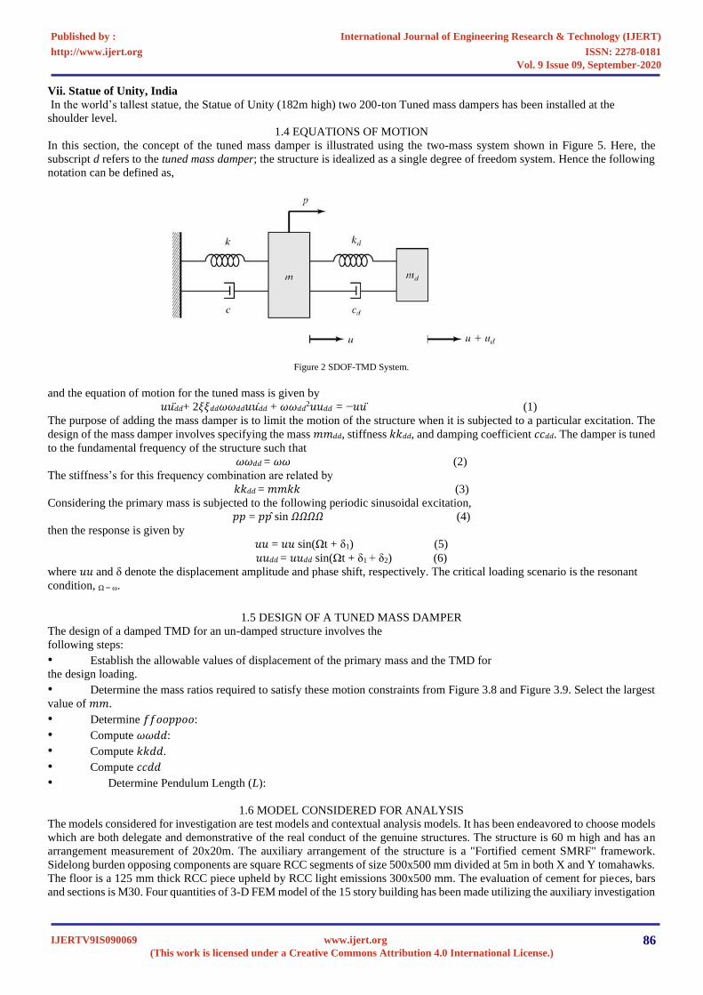
Table 4 Comparison of Response Spectrum Modal Information
Model 𝒎𝒎 Period Effective Damping U1/U2Acc
sec change % change m/sec2 change
Model-1 0.00 3.552 - 5.00% - 0.215 -
Model-2 0.01 3.814 7.38% 8.01% 60.2% 0.177 17.67%
Model-3 0.02 3.939 10.90% 9.27% 85.4% 0.164 23.72%
Model-4 0.04 4.143 16.64% 11.09% 121.8% 0.153 28.83%
1.8 RESULTS AND DISCUSSIONS.
Comparison of Base Reactions
The base reactions from the models Model-1, Model-2, Model-3 and Model-4 are listed below in Tables 4.
Table 4 Comparison of Base Reactions
. Output Case
Model-1 Model-2
𝒎𝒎 = 𝟎𝟎. 𝟎𝟎𝟎𝟎
Model-3
𝒎𝒎 = 𝟎𝟎. 𝟎𝟎𝟎𝟎
Model-4
𝒎𝒎 = 𝟎𝟎. 𝟎𝟎𝟎𝟎
FX FY FX FY FX FY FX FY
kN kN kN kN kN kN kN kN
EQX -1750 0 -1764 0 -1777 0 -1803 0
EQY 0 -1750 0 -1764 0 -1777 0 -1803
WLX -2030 0 -2030 0 -2030 0 -2030 0
WLY 0 -2030 0 -2030 0 -2030 0 -2030
SPECX 1750 0 1504 367 1438 348 1388 305
SPECY 0 1750 367 1504 348 1438 305 1388
TH_Bhuj 1179 1521 1399 1513 1339 1450 1230 1327
TH_Bhuj -1751 -1749 -1730 -1782 -1656 -1757 -1463 -1679
From the above results it can be seen that with the addition of the TMD,
the Base Shears of the building have changed except for the Wind load case. Since the effect of the TMD is supposed to be
captured in the Modal analysis cases only, there should not be any change in the Base Shear for EQX, EQY, WLX and WLY as
these are Static load cases. But the increase in Base Shear for EQX and EQY with the increasing mass ratio of the TMD is because
of the static weight of the TMD and the increment is 𝐴𝐴ℎ times the weight of TMD, which is usual.
For the Response Spectrum load cases SPECX and SPECY, the Base Shear has reduced with the increasing mass ratio, compared
to the base model. The reduction in Base Shear is 14.06%, 17.82% and 20.69% for the TMD mass ratios of 0.01, 0.02 and 0.04
respectively.
For the Time History load case the change in the Base shear is not substantial for the TMD mass ratios of 0.01 and 0.02, but the
Base Shear has decreased by 16.45% in X direction and 4.0% in Y direction for the mass ratio 0.04.
Comparison of Storey Displacements
The storey displacements from the models Model-1, Model-2, Model-3 and Model-4 are shown below in Figures 4.18 and 4.19.
The displacement responses of a joint at roof level for Time History load case are also shown in Figures 4.20, 4.21 and 4.22.
From these results it can be seen that with the addition of the TMD, the storey displacements of the building have reduced
significantly.
For the Response Spectrum load cases SPECX and SPECY, the reduction in storey displacements is 19.8%, 25.1% and 29.1%
for the TMD mass ratios of 0.01, 0.02 and 0.04 respectively.
For the Time History load case the reduction in the storey displacements is 10.5%, 15.5% and 23.4% for the TMD mass ratios of
0.01, 0.02 and 0.04 respectively
International Journal of Engineering Research & Technology (IJERT)
ISSN: 2278-0181http://www.ijert.org
IJERTV9IS090069(This work is licensed under a Creative Commons Attribution 4.0 International License.)
Published by :
www.ijert.org
Vol. 9 Issue 09, September-2020
88

.
Figure 3 Storey Displacements for SPECX and SPECY
International Journal of Engineering Research & Technology (IJERT)
ISSN: 2278-0181http://www.ijert.org
IJERTV9IS090069(This work is licensed under a Creative Commons Attribution 4.0 International License.)
Published by :
www.ijert.org
Vol. 9 Issue 09, September-2020
89

Figure 6 Storey Displacements for TH_Bhuj.
International Journal of Engineering Research & Technology (IJERT)
ISSN: 2278-0181http://www.ijert.org
IJERTV9IS090069(This work is licensed under a Creative Commons Attribution 4.0 International License.)
Published by :
www.ijert.org
Vol. 9 Issue 09, September-2020
90

Figure 7 Joint Displacement at Roof Level for TH_Bhuj.
International Journal of Engineering Research & Technology (IJERT)
ISSN: 2278-0181http://www.ijert.org
IJERTV9IS090069(This work is licensed under a Creative Commons Attribution 4.0 International License.)
Published by :
www.ijert.org
Vol. 9 Issue 09, September-2020
91

Figure 8 Joint Displacement at Roof Level for TH_Bhuj
-90
-70
-50
-30
-10
10
30
50
70
90
110
0 5 10 15 20 25 30 35 40 45 50
Time (sec)
no TMD m=0.02
-90
-70
-50
-30
-10
10
30
50
70
90
110
0 5 10 15 20 25 30 35 40 45 50
Time (ses)
no TMD m=0.02
International Journal of Engineering Research & Technology (IJERT)
ISSN: 2278-0181http://www.ijert.org
IJERTV9IS090069(This work is licensed under a Creative Commons Attribution 4.0 International License.)
Published by :
www.ijert.org
Vol. 9 Issue 09, September-2020
92

VB_Ymin = -1749 kN at 18.25 sec, VB_Ymax = 1521 kN at 20.05 sec.
Figure 11 Base Shear for Time History load case
CONCLUSION
In the present study the 3D model considered is 60 m tall building having 15 storeys with floor to floor height of 4 m. The building
has a square plan of 20x20 m. In this study both the building and the damper has been modelled as linear. Four numbers of
identical models were created, first model is the base model (uncontrolled) and the remaining three models (controlled) have
TMDs with mass ratios of 0.01, 0.02 and 0.04.
Linear time history analysis of the building has been done using the acceleration data of Bhuj/Kutch 2001 earthquake. Present
study focused on the ability of TMD to reduce earthquake induced structural vibration and to compare the building response with
effect of variation in mass ratio and damping ratio of TMD. From this study it can be concluded that.
The acceleration of the building in the fundamental mode is reduced by 17.67%, 23.72% and 28.83% for the mass ratios of
0.01, 0.02 and 0.04 respectively.
1) The effective damping of the building in the fundamental mode is increased to 8.01%, 9.27% and 11.09% for the mass
ratios of 0.01, 0.02 and 0.04 respectively.
2) The maximum storey displacement of the building is reduced by 19.8%, 25.1% and 29.1% for the mass ratios of 0.01,
0.02 and 0.04 respectively.
3) The effective damping of the building increases and the dynamic response of the building reduces as the mass ratio of
the TMD is increased. The TMD becomes robust with increasing mass ratio. Hence an optimal mass ratio of the TMD can be
found to reduce the building responses substantially there by giving a desired level of human comfort, safety and economy to the
structure.
Compliance with ethical standards
Conflict of interest on behalf of all authors, the corresponding author states that there is no conflict of interest.
REFERENCES [1] Kareem, A., Kijewski, Y, “Mitigation of Motions of Tall Buildings with Specific Examples of Recent Applications,” Wind and Structures., Vol. 2, No.
3, pp. 201-251 (1999).
[2] Introduction to Structural Motion Control, Jerome J. Connor.
[3] Seismic Analysis of Structures, T K Datta, IIT Delhi. [4] IS1893 (Part-1): 2016 ‘Criteria for Earthquake Resistant Design of Structures’.
[5] IS 875 (Part-3): 2015 ‘Design Loads (Other than Earthquake) for Buildings and Structures, Part-3 – Wind Load’.
[6] Taylor, D.P. and M.C. Constantinou. (1996), Fluid Dampers for Applications of Seismic Energy Dissipation and Seismic Isolation, Publication of Taylor Devices, Inc., 1996.
[7] Tamura, Y. (1997), Application of Damping Devices to Suppress WindInduced Responses of Buildings, Proceedings of the 2nd European and African
Conference on Wind Engineering, Palazzo Ducale, Genova, Italy, 1:45-60.
[8] Sakamoto, M. (9-10 Dec. 1993), Practical Applications of Active Structural Response Control and Earthquake &Strong Wind Observation Systems,
Planning Workshop for the Hong Kong International Full-Scale Control TestFacility, Hong Kong University of Science & Technology.
[9] Sakamoto, M. and Kobori, T. (Dec. 1996), Applications of Structural Response Control (Reviews from the Past and Issues Toward the Future), Proceedings of the Second International Workshop on Structural Control, Hong Kong.
[10] Kareem, A., (1983), Mitigation of Wind Induced Motion of Tall Buildings, Journal of Wind Engineering and Industrial Aerodynamics, 11(1-3): 273-
284. [11] Kareem, A. (1990), Reduction of Wind Induced Motion Utilizing a Tuned Sloshing, Journal of Wind Engineering and Industrial Aerodynamics, 36: 725-
37.
[12] Kareem, A. (27-30 June 1993), Tuned Liquid Dampers: Past, Present, and [13] Future, Proceedings of the 7th U.S. National Conference on Wind Engineering.
[14] Kareem, A., and M. Tognarelli. (Oct. 1994), Passive & Hybrid Tuned Liquid Dampers, Structural Engineering Forum: 26-30.
International Journal of Engineering Research & Technology (IJERT)
ISSN: 2278-0181http://www.ijert.org
IJERTV9IS090069(This work is licensed under a Creative Commons Attribution 4.0 International License.)
Published by :
www.ijert.org
Vol. 9 Issue 09, September-2020
93

[15] Symans, M.D. and M.C. Constantiou. (1996), Experimental Study of Seismic Response of Structures with Semi-Active Damping Control Systems, Proceedings of Structures Congress X.IV, Chicago, April 15-18.
[16] Spencer, B.F. Jr., and M.K. Sain (1997), Controlling Buildings: A New Frontier in Feedback, IEEE Control Systems,17(6): 19-35.
[17] Chang, K.C., Soong, T.T., Oh, S-T., and M.L. Lai. (1992), Effect of Ambient Temperature on a Viscoelastically Damped Structure, Journal of Structural Engineering, ASCE, 118(7): 1955-1973.
[18] Kawamura, M., Maebayashi, K., and K. Shimada. (1993), Application of a Tuned Mass Damper System Using Laminated Rubber Bearings to a Tower
Structure (Design, Test, and Recorded Vibration During Typhoons), Proc. of International Conference on Tall Buildings, Rio de Janerio. [19] Mahmoodi, P., Robertson, L.E., Yontar, M., Moy, C., and L. Feld. (1987), Performance of Viscoelastic Structural Dampers in World Trade Center
Towers, Dynamics of Structures, Structures Congress ‘87, Orlando, FL.
[20] Kitamura, H., Tamura, Y., and T. Ohkuma. (May 1995), Wind Resistant Design & Response Control in Japan Part III: Structural Damping & Response Control, Proceedings of 5th World Congress Council on Tall Buildings and Urban Habitat, Amsterdam.
[21] Soong, T.T. and G.F. Dargush. (1997), Passive Energy Dissipation Systems in Structural Engineering, Wiley & Sons, New York.
[22] Housner, G.W., et al. (1997), Structural Control: Past, Present and Future, Special Issue of Journal of Engineering Mechanics, 123(9). [23] Kwok, K.C.S. and N. Isyumov. (July 1998), Aerodynamic Measures to Reduce the Wind-Induced Response of Buildings and Structures, Proceedings of
Structural Engineers World Congress, San Francisco, CD-ROM: T179-6.
International Journal of Engineering Research & Technology (IJERT)
ISSN: 2278-0181http://www.ijert.org
IJERTV9IS090069(This work is licensed under a Creative Commons Attribution 4.0 International License.)
Published by :
www.ijert.org
Vol. 9 Issue 09, September-2020
94
![Vibration suppression of cables using tuned inerter dampers · tuned viscous mass dampers [28,29], tuned mass-damper-inerter systems [30] and tuned inerter dampers (TID) [31]. Unlike](https://static.fdocuments.in/doc/165x107/5ebe7d97c8153850be39552a/vibration-suppression-of-cables-using-tuned-inerter-dampers-tuned-viscous-mass-dampers.jpg)