Behaviour of Cable Bolts in Shear; Experimental Study and ...
16
University of Wollongong Research Online Coal Operators' Conference Faculty of Engineering and Information Sciences 2015 Behaviour of Cable Bolts in Shear; Experimental Study and Mathematical Modelling Naj Aziz University of Wollongong, [email protected] Peter Craig Jennmar Australia Ali Mirzaghorbanali University of Wollongong, [email protected] Haleh Rasekh University of Wollongong, [email protected] Jan Nemcik University of Wollongong, [email protected] See next page for additional authors Research Online is the open access institutional repository for the University of Wollongong. For further information contact the UOW Library: [email protected] Publication Details Naj Aziz, Peter Craig, Ali Mirza, Haleh Rasekh, Jan Nemcik and Xuwei Li, Behaviour of Cable Bolts in Shear; Experimental Study and Mathematical Modelling, 15th Coal Operators' Conference, University of Wollongong, e Australasian Institute of Mining and Metallurgy and Mine Managers Association of Australia, 2015, 146-159.
Transcript of Behaviour of Cable Bolts in Shear; Experimental Study and ...

University of WollongongResearch Online
Coal Operators' Conference Faculty of Engineering and Information Sciences
2015
Behaviour of Cable Bolts in Shear; ExperimentalStudy and Mathematical ModellingNaj AzizUniversity of Wollongong, [email protected]
Peter CraigJennmar Australia
Ali MirzaghorbanaliUniversity of Wollongong, [email protected]
Haleh RasekhUniversity of Wollongong, [email protected]
Jan NemcikUniversity of Wollongong, [email protected]
See next page for additional authors
Research Online is the open access institutional repository for the University of Wollongong. For further information contact the UOW Library:[email protected]
Publication DetailsNaj Aziz, Peter Craig, Ali Mirza, Haleh Rasekh, Jan Nemcik and Xuwei Li, Behaviour of Cable Bolts in Shear; Experimental Study andMathematical Modelling, 15th Coal Operators' Conference, University of Wollongong, The Australasian Institute of Mining andMetallurgy and Mine Managers Association of Australia, 2015, 146-159.

AuthorsNaj Aziz, Peter Craig, Ali Mirzaghorbanali, Haleh Rasekh, Jan Nemcik, and Xuwei Li
This conference paper is available at Research Online: http://ro.uow.edu.au/coal/559
2015 Coal Operators’ Conference The University of Wollongong
146 11 – 13 February 2015
BEHAVIOUR OF CABLE BOLTS IN SHEAR; EXPERIMENTAL
STUDY AND MATHEMATICAL MODELLING
Naj Aziz1, Peter Craig2, Ali Mirza1, Haleh Rasekh1, Jan Nemcik1 and Xuwei Li1
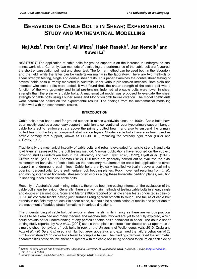
ABSTRACT: The application of cable bolts for ground support is on the increase in underground coal mines worldwide. Currently, two methods of evaluating the performance of the cable bolt are favoured; the short encapsulation pull test and shear test. The former method can be used both in the laboratory and the field, while the latter can be undertaken mainly in the laboratory. There are two methods of shear strength testing, single and double shear tests. This paper examines the double shear testing of several cable bolts currently marketed in Australia under various pre-tension stresses. Both plain and indented wire cable bolts were tested. It was found that, the shear strength of the cable bolt was a function of the wire geometry and initial pre-tension. Indented wire cable bolts were lower in shear strength than the plain wire cable bolts. A mathematical model was proposed to evaluate the shear strength of cable bolts using Fourier series and Mohr-Coulomb failure criterion. The model coefficients were determined based on the experimental results. The findings from the mathematical modelling tallied well with the experimental results.
INTRODUCTION Cable bolts have been used for ground support in mines worldwide since the 1960s. Cable bolts have been mostly used as a secondary support in addition to conventional rebar type primary support. Longer cable bolts act to reinforce strata above the primary bolted beam, and also to suspend the primary bolted beam to the higher competent stratification layers. Shorter cable bolts have also been used as flexible primary roof support, known as FLEXIBOLT, replacing the ordinary rigid rebar (Fuller and O’Grady, 1993). Traditionally the mechanical integrity of cable bolts and rebar is evaluated for tensile strength and axial load transfer assessed by the pull testing method. Various publications have reported on the subject, covering studies undertaken both in the laboratory and field; Hyett et al., (1992), Hyett et al., (1996), Clifford et al., (2001); and Thomas (2012). Pull tests are generally carried out to evaluate the axial reinforcement behaviour of cable bolts as the necessary requirement for cable bolt application to strata support in underground coal mines. Cable bolts are typically installed vertically above a coal mine opening, perpendicular to the sedimentary rock bedding planes. Rock movement resulting from in situ and mining intensified horizontal stresses often occurs along these horizontal bedding planes, resulting in shearing loads across the cable bolts. Recently in Australia’s coal mining industry, there has been increasing interest on the evaluation of the cable bolt shear behaviour. Generally, there are two main methods of testing cable bolts in shear, single and double shear methods. Goris and Martin (1996) reported on single shear tests conducted in pairs of 0.025 m3 concrete blocks having joint surfaces ranging from smooth to rough. The failure of cable bolt strands in the field may not occur in shear alone, but could be a combination of tensile and shear due to the movement of bedded strata formations in various directions. The understanding of cable bolt behaviour in shear is still in its infancy as there are various practical issues to be examined and many theories and mechanisms involved are yet to be fully explored, which could provide better understanding of any particular cable bolt’s behaviour in shear. The double shear testing study reported by Aziz et al., (2004) used a three piece concrete block double shear apparatus to simulate shear behaviour of rock bolts in rock at the University of Wollongong. Aziz, 2010, Craig and Aziz et al., (2010a and b) used a similar but larger apparatus and examined the failure behaviour of 28 mm hollow strand “TG” cable bolts taken to complete failure. Their findings demonstrated the symmetric characteristics of the double shear equipment with the cable bolt being sheared to failure on each side of
1 School of Civil, Mining and Environmental Engineering, University of Wollongong, NSW, Australia. E-mail: [email protected], Tel: +61 242213449 2 Jennmar Australia, 40-44 Anzac Ave, Smeaton Grange, NSW, Australia, 2567
2015 C
11 –13
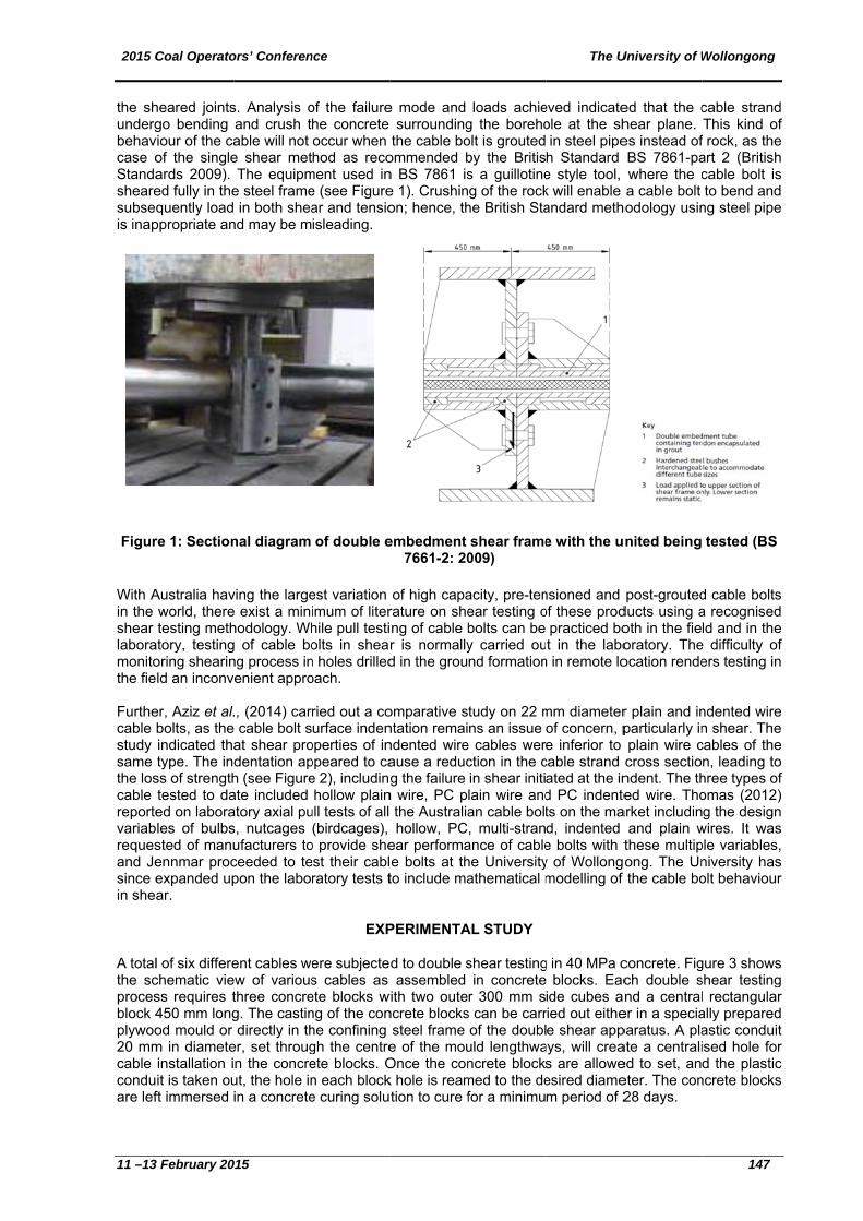
the shundergbehavcase oStandashearesubseqis inap
Figur
With Ain the shear laboramonitothe fie Furthecable study same the loscable reportevariabrequesand Jesince ein she
A totalthe scprocesblock 4plywoo20 mmcable conduare lef
Coal Operato
3 February 20
heared jointsgo bending
viour of the caof the singleards 2009). ed fully in thequently load
ppropriate an
re 1: Section
Australia havworld, theretesting meth
atory, testingoring shearinld an inconv
er, Aziz et al.bolts, as theindicated thatype. The in
ss of strengthtested to daed on laborales of bulbssted of manuennmar procexpanded upar.
l of six differechematic viess requires t450 mm longod mould or m in diameteinstallation iit is taken ouft immersed
ors’ Conferen
015
s. Analysis oand crush table will not e shear metThe equipm
e steel frame in both shea
nd may be m
nal diagram
ving the largee exist a minhodology. Whg of cable bong process inenient appro
., (2014) car cable bolt sat shear prodentation aph (see Figureate included atory axial pus, nutcages ufacturers toceeded to tepon the labo
ent cables weew of variousthree concreg. The castindirectly in th
er, set througn the concreut, the hole inin a concrete
nce
of the failurehe concrete occur when hod as reco
ment used ine (see Figurear and tensioisleading.
of double e
est variation imum of literhile pull testiolts in shear
n holes drilledoach.
ried out a courface inden
operties of inppeared to cae 2), includinghollow plain
ull tests of all (birdcages),
o provide sheest their cablratory tests t
EXP
ere subjectes cables as ete blocks wng of the conhe confining gh the centreete blocks. On each blocke curing solu
e mode and surrounding
the cable boommended bn BS 7861 ise 1). Crushinon; hence, th
embedment 7661-2: 20
of high caparature on sheng of cable br is normallyd in the grou
omparative sntation remaindented wireause a reducg the failure
n wire, PC p the Australiahollow, PC
ear performae bolts at thto include ma
PERIMENTA
d to double sassembled
with two outencrete blocks
steel frame e of the mouOnce the conk hole is reamtion to cure f
loads achieg the borehoolt is grouted by the Britiss a guillotineg of the rock
he British Sta
shear frame009)
acity, pre-tenear testing obolts can be y carried ound formation
tudy on 22 mns an issue
e cables werction in the cin shear initilain wire andan cable bolt, multi-stran
ance of cablehe Universityathematical m
AL STUDY
shear testingin concrete
r 300 mm ss can be carrof the doubl
uld lengthwancrete blocksmed to the defor a minimu
The U
eved indicateole at the shin steel pipeh Standard e style tool, k will enable andard meth
e with the u
nsioned and of these prod
practiced bot in the labo
n in remote lo
mm diameterof concern, pe inferior to
cable strand ated at the ind PC indentets on the mad, indented e bolts with ty of Wollongomodelling of
g in 40 MPa cblocks. Eac
ide cubes aried out eithee shear app
ays, will creas are alloweesired diamem period of 2
University of W
ed that the chear plane. es instead ofBS 7861-pawhere the ca cable bolt
hodology usin
nited being
post-groutedducts using aoth in the fieoratory. Theocation rende
r plain and inparticularly inplain wire ccross sectiondent. The thed wire. Tho
arket includinand plain wthese multipong. The Unthe cable bo
concrete. Figch double snd a central
er in a speciaparatus. A plaate a centralied to set, aneter. The con28 days.
Wollongong
147
cable strandThis kind of
f rock, as theart 2 (Britishcable bolt isto bend and
ng steel pipe
tested (BS
d cable boltsa recognisedld and in the
e difficulty ofers testing in
ndented wiren shear. Thecables of then, leading tohree types ofomas (2012)g the design
wires. It wasple variables,niversity hasolt behaviour
gure 3 showsshear testingl rectangularally preparedastic conduitised hole ford the plastic
ncrete blocks
d f
e h s d e
s d e f n
e e e o f ) n s , s r
s g r d t r c s

2015 Coal Operators’ Conference The University of Wollongong
148 11 – 13 February 2015
Figure 2: Tensile load / elongation profiles of both plain and indented 5.5 mm wire from cable bolts
Garford Twin-Strand
Non-Birdcaged Cables
Birdcaged Cables
Figure 3: Cross section of double shear blocks and cables The cured blocks are then mounted in the double shear confining steel frames and the cable bolt specimen placed into the borehole. Two 60 t load cells were inserted onto each end of the cable followed by the typical cable bolt end fitting. The load cells were connected to the data logger during tensioning. Once the cable is pretensioned, the grout is injected to the annulus between the cable and borehole through the intersecting small holes on top of the block. Cables with hollow central tubes were also filled with grout, and the grout or polyester resin left to cure for at least 7 days. The top of the concrete blocks are covered by the bolted steel plates and the whole assembly is then mounted on the carried base platform. The whole double shear assembly and the base frame is then mounted on to the 500 t compression testing machine for shearing process as shown in Figure 4.

2015 Coal Operators’ Conference The University of Wollongong
11 –13 February 2015 149
Figure 4: Arrangement of shearing apparatus on compression machine The properties of the eight different cable bolts are described in Table 1. The study focussed on the main cables in the market as supplied by Jennmar, with indented wire hollow cable included for additional research. Cables were subjected to three different values of initial axial load ranging from 0 to 25 t. Three types of bonding agent were used in this particular study; Jennmar bottom-up grout (BU100), Jennmar top-down grout (TD80) and J-Lok standard oil based resin. The values of shear and axial loads versus shear displacement were monitored and recorded. The shear and axial stresses were calculated using following equations:
CA
Nn (1)
CA
S
2
9.0 (2)
where, σn is the normal stress, N is the normal load, CA is cable area, is the shear stress and S is the shear load. It is noted that 10% of the shear load was ascribed to the rubbing of concrete surfaces and therefore 90% of the measured shear load incorporated as shown in Equation (2) in calculating the value of shear stress. The rubbing of concrete surface was evaluated by painting the concrete surfaces in checkered pattern before shearing. The damaged pattern on concrete surfaces was then carefully examined after dismantling the double shear apparatus. Figure 5 shows a typical checkered sheared face, which clearly shows approximately the percentage part of the surface damage during the shear process. Due to the significant stiffness of the cable, it is therefore rational to postulate that the shear load almost concentrates on the cable cross sectional area rather than on the concrete surfaces. The process of double shear testing consists of loading the central block vertically in the 500 t compression testing machine (Figure 4). The 450 mm long middle section of the double shear apparatus is then vertically shear loaded at the rate of 1 mm/min for the maximum100 mm vertical displacement.

2015 Coal Operators’ Conference The University of Wollongong
150 11 – 13 February 2015
The rate of loading and displacement are monitored and simultaneously displayed visually on a PC monitor.
Table 2: list of tested cables and the test environment
Figure 5: A typical concrete block surface after shearing
MATHEMATICAL MODELING
The mathematical model was developed by assuming the linear Mohr-Coulomb relationship between the shear and normal stresses as (in below equation, surface roughness has been omitted):
0)tan( cn (3)
where, φ is the friction angle and c is the cohesion.
2015 Coal Operators’ Conference The University of Wollongong
11 –13 February 2015 151
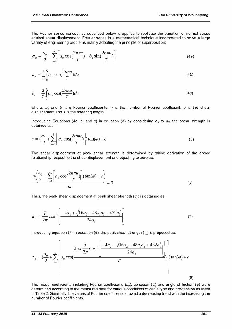
The Fourier series concept as described below is applied to replicate the variation of normal stress against shear displacement. Fourier series is a mathematical technique incorporated to solve a large variety of engineering problems mainly adopting the principle of superposition:
1
0 )2
sin()2
cos(2 n
nnn T
unb
T
una
a (4a)
T
nn duT
un
Ta
0
)2
cos(2 (4b)
T
nn duT
un
Tb
0
)2
cos(2 (4c)
where, an and bn are Fourier coefficients, n is the number of Fourier coefficient, u is the shear displacement and T is the shearing length. Introducing Equations (4a, b, and c) in equation (3) by considering a0 to a3, the shear strength is obtained as:
3
1
0 )tan())2
cos(2
(n
n cT
una
a (5)
The shear displacement at peak shear strength is determined by taking derivation of the above relationship respect to the shear displacement and equating to zero as:
0
)tan())2
cos(2
3
1
0
du
cT
una
ad
nn
(6)
Thus, the peak shear displacement at peak shear strength (up) is obtained as:
3
2331221
24
43248164cos
2 a
aaaaaTu p
(7)
Introducing equation (7) in equation (5), the peak shear strength (τp) is proposed as:
3
1
3
2331221
0 )tan())24
43248164cos
22
cos(2
(n
np cT
a
aaaaaTn
aa
(8)
The model coefficients including Fourier coefficients (an), cohesion (C) and angle of friction (φ) were determined according to the measured data for various conditions of cable type and pre-tension as listed in Table 2. Generally, the values of Fourier coefficients showed a decreasing trend with the increasing the number of Fourier coefficients.

2015 Coal Operators’ Conference The University of Wollongong
152 11 – 13 February 2015
RESULTS AND ANALYSIS
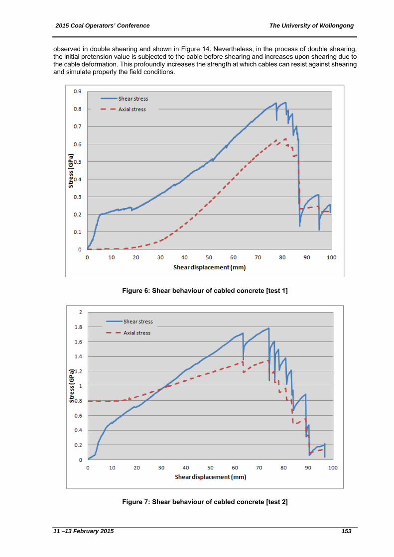
Figures 6 to13 show the shear stress and axial stress profiles against shear displacement for the tests conducted in this study. The initial changes in some of the shear stress graphs after the elastic state may be related to the barrel/wedge settlement as the cable ends begins to take axial load due to cable bending at the shear planes. Various shear drops beyond the peak value are attributed to individual cable strand failures. The larger shear drop corresponds to the higher diameter strand failure while the smaller ones are due to the small strand failures. It is of interest to note that the number of visible sudden drops in stress upon shear displacement is equal or slightly less than the number of failed strand, which might be due to two strands snapping near the same time. The strand failure in the cable at the shear plane was also observed as load drop at the load cells measuring axial load near the end fittings. Figure 14 shows snapped strands of the tested cables. It is obvious that the failures of strands in the cable is a mix of tensile and shear, depending on the location of the strand in the cable cross-section, the direction of the shearing and cable construction. For multiple mixed wire diameter cables of the superstrand cable, it was observed that smaller diameter strands of the inner layer appears to fail in tension with con and cup pattern (Aziz et al.,2014 a, b).
Table 2: Model coefficients for different types
Table 3 summarises the peak shear strength of the different cable bolt and testing configurations. It is obvious from the results that the plain wire birdcaged cables had higher shear strength when compared to the indented wire birdcaged cables. The shear performance of non-birdcaged superstrand and hollow TG cable was lower when wires were indented, but the shear strength was still close to the UTS (Uniaxial Tensile Strength) of the cable bolts. The lower shear behavior of the indented wire of the same cable type was likely attributed to the fact that the indented wires have a small cross section and the indent geometry forms a stress raiser to initiate failure. The indented wire cable bolts display lower deflection (stiffer) than the plain wire equivalent type. No cable rotation was observed in either the plain or indented strand cable bolts during the double shearing tests. As can be seen from Figure 15, the shear strength of cable bolted concrete block subjected to shearing can be represented reasonably by the proposed model for different initial pretension stresses, bonding agents and cable bolts. In order to compare the method of double shearing used in this study with single shear test of British Standard, Superstrand cables both indented and plane ones were also sheared as suggested by British Standards (2009). Figure 16 shows the comparison between the shear load against shear displacement using double shear and single shear test methods. It is inferred that the single shear testing method significantly underestimates the shear strength of Super strand cable bolts. The conspicuous difference between the value of shear load in single shear and double shear tests can be related to the fact that the single shear test is only a metal to metal shearing and does not carry any pretension or axial load during shearing. Thus, all the strands only experience shear failure without having any tension failure as
2015 Coal Operators’ Conference The University of Wollongong
11 –13 February 2015 153
observed in double shearing and shown in Figure 14. Nevertheless, in the process of double shearing, the initial pretension value is subjected to the cable before shearing and increases upon shearing due to the cable deformation. This profoundly increases the strength at which cables can resist against shearing and simulate properly the field conditions.
Figure 6: Shear behaviour of cabled concrete [test 1]
Figure 7: Shear behaviour of cabled concrete [test 2]

2015 Coal Operators’ Conference The University of Wollongong
154 11 – 13 February 2015
Figure 8: Shear behaviour of cabled concrete [test 3]
Figure 9: Shear behaviour of cabled concrete [test 4]

2015 Coal Operators’ Conference The University of Wollongong
11 –13 February 2015 155
Figure 10: Shear behaviour of cabled concrete [test 5]
Figure 11: Shear behaviour of cabled concrete [test 6]

2015 Coal Operators’ Conference The University of Wollongong
156 11 – 13 February 2015
Figure 12: Shear behaviour of cabled concrete [test 7]
Figure 13: Shear behaviour of cabled concrete [test 8]

2015 Coal Operators’ Conference The University of Wollongong
11 –13 February 2015 157
Table 3: Peak shear stress for different cabled concrete blocks
Figure 14: strands snapped of the tested cables

2015 Coal Operators’ Conference The University of Wollongong
158 11 – 13 February 2015
Figure 15: Comparison between the model results and measured data
Figure 16: Comparison between the double and single shear methods
CONCLUSIONS AND RECOMMENDATIONS
The following conclusions are drawn from this investigation:
a) Indented wire combined with birdcaging of cable bolts is detrimental to the cable shear performance.
b) Shear strength of non-birdcaged cables bolts are less affected by indentation of the wire. c) It is likely that the reduced cross-section reduces tensile strength and the geometry forms a
stress raiser to initiate failure. d) A mathematical model was proposed incorporating Mohr-Coulomb failure criterion and Fourier
series concept to simulate the shear strength of cabled concrete blocks. e) The values of Fourier coefficients decreased as the number of Fourier coefficients increased.

2015 Coal Operators’ Conference The University of Wollongong
11 –13 February 2015 159
Recommendations include:
a) Due attention must be given to the study of the cable shear across closed and interlocking sheared beds as well as across separated beds with no contacts between sheared faces.
b) More experiments are suggested to calibrate the model for practical purposes. c) The double shear method in simulated rock has proven to provide valuable insight into in-situ
performance. The British Standard BS 7861 (part 2)* cannot be applied to the study of shear behaviour of the cable bolt in rock. The equipment used in the BS 7861 (part 2) is a guillotine style tool, where the cable bolt is sheared fully in the steel frame. Shearing of the cable bolt in rock normally undergoes both shear and tension; hence, the British standard methodology is inappropriate and may be misleading.
REFERENCES
Aziz, N. 2014a, Double shear testing cable-bolts for Jennmar Australia, a report of study prepared for Jennmar Australia, School of Civil, Mining and Environmental Engineering, University of Wollongong, May 27, 9p.
Aziz, N. 2014b, Double shear testing of Secura Hollow Groutable Cable-bolt (SHGC) for Orica Australia Pty Ltd, a report of study, School of Civil, Mining and Environmental Engineering, University of Wollongong, July, 9p.
Aziz, N, Heemann, K, Nemcik J and Mayer, S. 2014, Shear strength properties of Hilti plain and indented strand cable bolts, in proceedings Coal Operators Conference (Coal 2014), Wollongong, February 12-14, ISBN 978 1 925100 02 0, pp156-162 (Eds. N Aziz, B Kinninmonth), http://ro.uow.edu.au/coal/509/.
Aziz, N, Nemcik, J, Jalalifar, H. 2011, Double shearing of rebar and cable bolts for effective strata reinforcement, in proceedings 12th ISRM International Congress on Rock Mechanics, Beijing, China, 18-21, October. Pp 1457-1460. Published in Harmonising Rock Engineering and the Environment –Qian and Zhou (Eds), 2012 Taylor and Francis Group, London, ISBN, 978-0-415-80444-8.
British Standard BS 7861- Parts 1 and 2. 1996, Strata Reinforcement support system components used in Coal Mines-Part 1, Specification for rock bolting and Part 2: Specification for Flexible systems for roof reinforcement.
Clifford, B, Kent, L, Altounyan, P, Bigby, D. 2001, Systems used in Coal Mine Developments in Long Tendon Reinforcement, 20th International Conference on Ground Control in Mining. ICGCM, http://icgcm.conferenceacademy.com/papers/detail.aspx?subdomain=icgcm&iid=735.
Craig, P and Aziz, N. 2010a, Shear testing of 28 mm Hollow Strand “TG” Cable Bolt, in proceedings 10th Underground Coal operators Conference, Wollongong, February 11/12, pp171-179 (Ed.N Aziz and Jan Nemcik. 375 p), http://ro.uow.edu.au/coal/303/.
Craig, P and Aziz, N. 2010b, Shear testing of 28 mm hollow strand "TG" cable bolt, In proceedings 29th International Conference on Ground Control in Mining, ICGCM (pp. 169-174), (Publication ID=35591), http://icgcm.conferenceacademy.com/papers/detail.aspx?subdomain=icgcm&iid=273.
Goris, JM, Martin LA.1996, Shear behaviour of cable bolt supports in Horizontal bedded deposit. Laboratory pull tests of resin –grouted cable bolts, 15th International Conference on Ground Control in Mining, Golden, Colorado, August 13-15, pp 511-521, http://icgcm.conferenceacademy.com/papers/paperlist.aspx?iid=407.
Fuller PG, O’Grady P. 1993, FLEXIBOLT flexible roof bolts: A new concept for strata control, 12th International Conference on Ground Control in Mining, Morgantown, West Virginia, USA, pp 24-34, http://icgcm.conferenceacademy.com/ebook/view.aspx?PaperID=1235.
Hyett AJ, Bawden WF, and Reichert RD. 1992, The effect of rock mass confinement on the bond strength of fully grouted cable bolts, Int. J. Rock mechanics and Min. Sci. & Geomech. Abstr, 29(5), pp 503-524.
Hyett AJ, Mossavi M and Bawden WF. 1996, Load distribution along fully grouted bolts, with emphasis on cable bolt reinforcement, Int. J. for Numerical and Analytical Methods in Geomechanics, 20, pp 517-544.
Thomas, R. 2012, The load transfer properties of post-groutable cable bolts used in the Australian coal industry, 31st International Conference on Ground Control in Mining, Morgantown, 10p, http://icgcm.conferenceacademy.com/papers/detail.aspx?subdomain=icgcm&iid=1011.
View publication statsView publication stats