BEHAVIOR OF LIGHT WEIGHT CONCRETE SOLID SLABS …
10
International Journal of Civil and Structural Engineering Research ISSN 2348-7607 (Online) Vol. 8, Issue 1, pp: (151-160), Month: April 2020 - September 2020, Available at: www.researchpublish.com Page | 151 Research Publish Journals BEHAVIOR OF LIGHT- WEIGHT CONCRETE SOLID SLABS REINFORCED USING G.F.R.P. REBAR 1 Alaa G. Sherif, 2 Nasr Z. Hassan, 3 Mohamed Saber, 4 Mirhan W. Adly 1 Prof. of Concrete Structures, Faculty of Eng., Mattaria, Helwan Univ., Cairo, Egypt 2 Assoc. Prof. of Concrete Structures, Faculty of Eng., Mattaria, Helwan Univ., Cairo, Egypt 3 Teacher, Construction Engineering Dept., Egyptian Russian University, Cairo, Egypt 4 Teaching Assistant, Construction Engineering Dept., Egyptian Russian University, Cairo, Egypt Abstract: Deterioration of concrete structures throughout the world and the cost of their repair and rehabilitation have become a major concern to engineer and researchers in recent years. Almost cases the repair costs can be twice or more of the original cost. For example, in Canada, it is estimated that the cost of repair of parking garages is in the range of 6 billion dollars, and over 74 billion dollars for all concrete structures. The estimated repair cost for existing highway bridges in the USA is over 50 billion dollars, and 1-3 trillion dollars for all concrete structures. In Europe, steel corrosion has been estimated to cost about 3 billion dollars’ year. Excessive corrosion problem also exists in Arabian Gulf countries (Benmokrane et al., 1998). Organizations, private industry and university researchers are seeking ways to avoid the corrosion problem and thereby eliminate, partially or totally, burden of never ending repair costs. One preferred solution, which has assumed the status of cutting edge research in many industrialized countries, is the use of fiber reinforced polymer (FRP) rebars in concrete. FRP reinforcement has an advantage over steel in that it has high corrosion resistance and a high strength to weight ratio, thus for structures built in or close to seawater or at similar corrosive environment. They are also non-conductive for electricity and non-magnetic. Keywords: Solid plates, Flexure strength, GFRP rebar, Crack pattern. 1. INTRODUCTION In this study, details of the experimental program consisting of testing 12 full scale concrete slabs subjected to moment loading is are presented. The main objectives of the experimental program are: 1) to investigate the behavior of using steel and GFRP bars to enhance the moment strength of reinforced concrete slabs. 2) to optimize the GFRP bars ratio that leads to the ultimate load carrying capacity. 3) To compare between different reinforcement steel and GFRP bars as a main reinforcement in behavior on type of load of light weight concrete slabs one and two way. 4) To address the deformation and ductility behavior of light weight concrete slabs having steel and GFRP bars. 5) To studding behavior of light weight concrete with steel and GFRP bars as a main reinforcement. 2. EXPERMINTAL STUDY The tested specimens were categorized into two groups as shown in Table 1. The first group (Group I) as a one-way slabs had six slabs. Three slabs were reinforced by steel and other three slabs reinforced by GFRP with different ratio of reinforcement. The results of the first three specimens of the Group-I were meant to be the reference for the results of the other specimens. The second group (Group II) has the same parameter of group but with different dimension as a two-way slab. Results of specimens this Groups I,II were used to understand the behavior of concrete slabs having fiber. The slabs in these groups were tested under monotonic load condition. They had different reinforcement ratio with different dimensions of the slab. Table 3.1 summarizes the geometric characteristics of all tested specimens.
Transcript of BEHAVIOR OF LIGHT WEIGHT CONCRETE SOLID SLABS …
International Journal of Civil and Structural Engineering Research ISSN 2348-7607 (Online) Vol. 8, Issue 1, pp: (151-160), Month: April 2020 - September 2020, Available at: www.researchpublish.com
Page | 151 Research Publish Journals
BEHAVIOR OF LIGHT- WEIGHT
CONCRETE SOLID SLABS REINFORCED
USING G.F.R.P. REBAR
1Alaa G. Sherif,
2Nasr Z. Hassan,
3Mohamed Saber,
4Mirhan W. Adly
1 Prof. of Concrete Structures, Faculty of Eng., Mattaria, Helwan Univ., Cairo, Egypt
2 Assoc. Prof. of Concrete Structures, Faculty of Eng., Mattaria, Helwan Univ., Cairo, Egypt
3Teacher, Construction Engineering Dept., Egyptian Russian University, Cairo, Egypt
4 Teaching Assistant, Construction Engineering Dept., Egyptian Russian University, Cairo, Egypt
Abstract: Deterioration of concrete structures throughout the world and the cost of their repair and rehabilitation
have become a major concern to engineer and researchers in recent years. Almost cases the repair costs can be
twice or more of the original cost. For example, in Canada, it is estimated that the cost of repair of parking garages
is in the range of 6 billion dollars, and over 74 billion dollars for all concrete structures. The estimated repair cost
for existing highway bridges in the USA is over 50 billion dollars, and 1-3 trillion dollars for all concrete
structures. In Europe, steel corrosion has been estimated to cost about 3 billion dollars’ year. Excessive corrosion
problem also exists in Arabian Gulf countries (Benmokrane et al., 1998). Organizations, private industry and
university researchers are seeking ways to avoid the corrosion problem and thereby eliminate, partially or totally,
burden of never ending repair costs. One preferred solution, which has assumed the status of cutting edge research
in many industrialized countries, is the use of fiber reinforced polymer (FRP) rebars in concrete.
FRP reinforcement has an advantage over steel in that it has high corrosion resistance and a high strength to
weight ratio, thus for structures built in or close to seawater or at similar corrosive environment. They are also
non-conductive for electricity and non-magnetic.
Keywords: Solid plates, Flexure strength, GFRP rebar, Crack pattern.
1. INTRODUCTION
In this study, details of the experimental program consisting of testing 12 full scale concrete slabs subjected to moment
loading is are presented. The main objectives of the experimental program are: 1) to investigate the behavior of using steel
and GFRP bars to enhance the moment strength of reinforced concrete slabs. 2) to optimize the GFRP bars ratio that leads
to the ultimate load carrying capacity. 3) To compare between different reinforcement steel and GFRP bars as a main
reinforcement in behavior on type of load of light weight concrete slabs one and two way. 4) To address the deformation
and ductility behavior of light weight concrete slabs having steel and GFRP bars. 5) To studding behavior of light weight
concrete with steel and GFRP bars as a main reinforcement.
2. EXPERMINTAL STUDY
The tested specimens were categorized into two groups as shown in Table 1. The first group (Group I) as a one-way slabs
had six slabs. Three slabs were reinforced by steel and other three slabs reinforced by GFRP with different ratio of
reinforcement. The results of the first three specimens of the Group-I were meant to be the reference for the results of the
other specimens. The second group (Group II) has the same parameter of group but with different dimension as a two-way
slab. Results of specimens this Groups I,II were used to understand the behavior of concrete slabs having fiber. The slabs
in these groups were tested under monotonic load condition. They had different reinforcement ratio with different
dimensions of the slab. Table 3.1 summarizes the geometric characteristics of all tested specimens.
International Journal of Civil and Structural Engineering Research ISSN 2348-7607 (Online) Vol. 8, Issue 1, pp: (151-160), Month: April 2020 - September 2020, Available at: www.researchpublish.com
Page | 152 Research Publish Journals
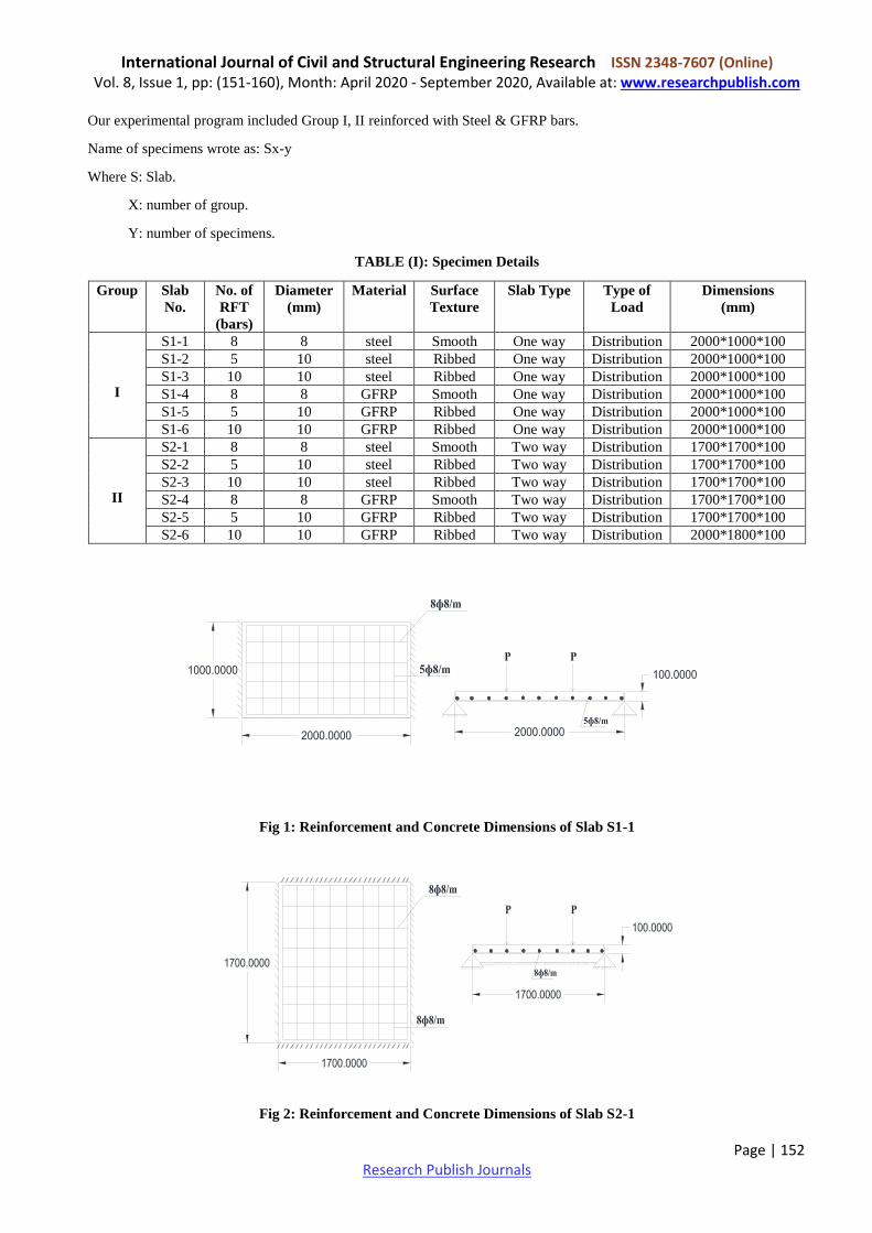
Our experimental program included Group I, II reinforced with Steel & GFRP bars.
Name of specimens wrote as: Sx-y
Where S: Slab.
X: number of group.
Y: number of specimens.
TABLE (I): Specimen Details
Group Slab
No.
No. of
RFT
(bars)
Diameter
(mm)
Material Surface
Texture
Slab Type Type of
Load
Dimensions
(mm)
I
S1-1 8 8 steel Smooth One way Distribution 2000*1000*100
S1-2 5 10 steel Ribbed One way Distribution 2000*1000*100
S1-3 10 10 steel Ribbed One way Distribution 2000*1000*100
S1-4 8 8 GFRP Smooth One way Distribution 2000*1000*100
S1-5 5 10 GFRP Ribbed One way Distribution 2000*1000*100
S1-6 10 10 GFRP Ribbed One way Distribution 2000*1000*100
II
S2-1 8 8 steel Smooth Two way Distribution 1700*1700*100
S2-2 5 10 steel Ribbed Two way Distribution 1700*1700*100
S2-3 10 10 steel Ribbed Two way Distribution 1700*1700*100
S2-4 8 8 GFRP Smooth Two way Distribution 1700*1700*100
S2-5 5 10 GFRP Ribbed Two way Distribution 1700*1700*100
S2-6 10 10 GFRP Ribbed Two way Distribution 2000*1800*100
Fig 1: Reinforcement and Concrete Dimensions of Slab S1-1
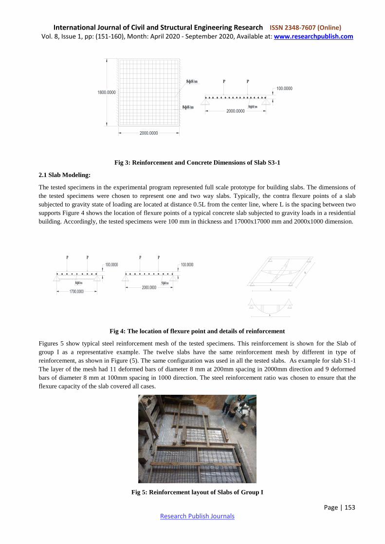
Fig 2: Reinforcement and Concrete Dimensions of Slab S2-1
International Journal of Civil and Structural Engineering Research ISSN 2348-7607 (Online) Vol. 8, Issue 1, pp: (151-160), Month: April 2020 - September 2020, Available at: www.researchpublish.com
Page | 153 Research Publish Journals
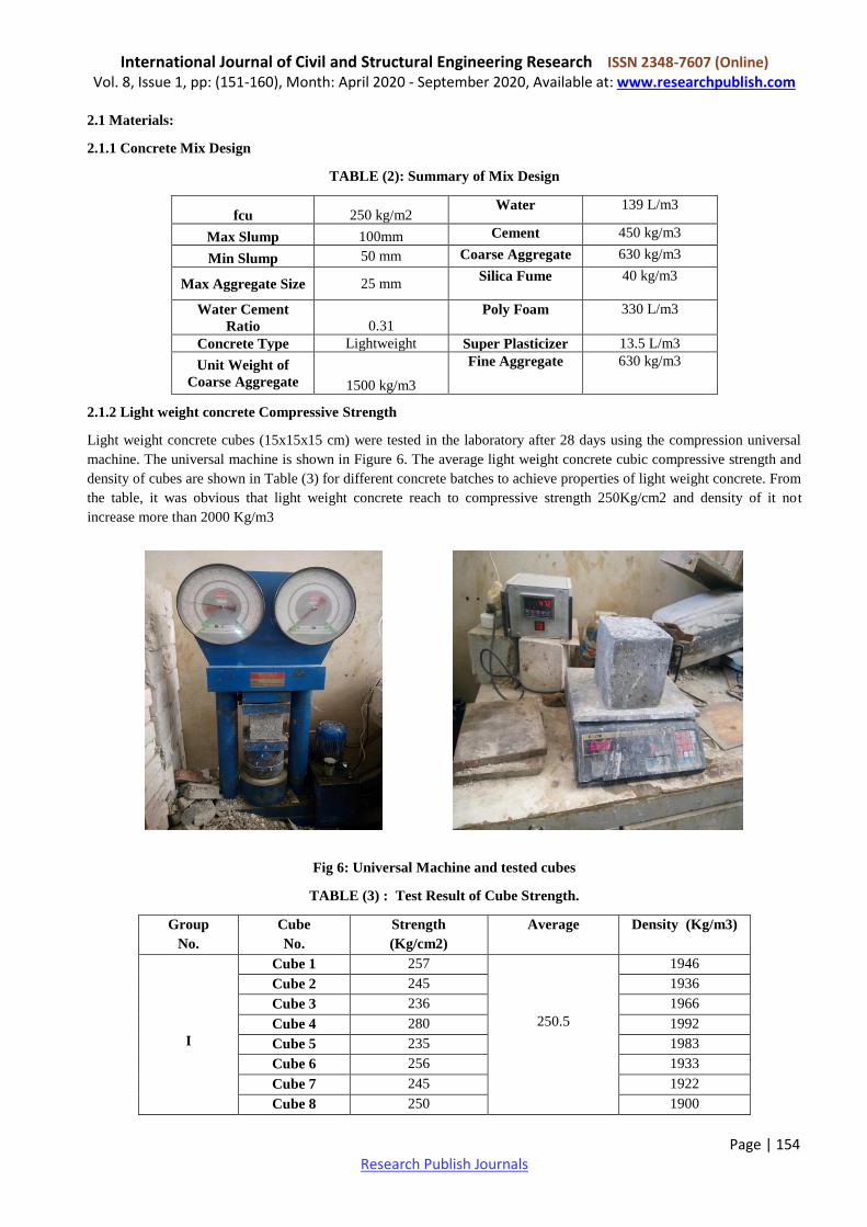
Fig 3: Reinforcement and Concrete Dimensions of Slab S3-1
2.1 Slab Modeling:
The tested specimens in the experimental program represented full scale prototype for building slabs. The dimensions of
the tested specimens were chosen to represent one and two way slabs. Typically, the contra flexure points of a slab
subjected to gravity state of loading are located at distance 0.5L from the center line, where L is the spacing between two
supports Figure 4 shows the location of flexure points of a typical concrete slab subjected to gravity loads in a residential
building. Accordingly, the tested specimens were 100 mm in thickness and 17000x17000 mm and 2000x1000 dimension.
Fig 4: The location of flexure point and details of reinforcement
Figures 5 show typical steel reinforcement mesh of the tested specimens. This reinforcement is shown for the Slab of
group I as a representative example. The twelve slabs have the same reinforcement mesh by different in type of
reinforcement, as shown in Figure (5). The same configuration was used in all the tested slabs. As example for slab S1-1
The layer of the mesh had 11 deformed bars of diameter 8 mm at 200mm spacing in 2000mm direction and 9 deformed
bars of diameter 8 mm at 100mm spacing in 1000 direction. The steel reinforcement ratio was chosen to ensure that the
flexure capacity of the slab covered all cases.
Fig 5: Reinforcement layout of Slabs of Group I
International Journal of Civil and Structural Engineering Research ISSN 2348-7607 (Online) Vol. 8, Issue 1, pp: (151-160), Month: April 2020 - September 2020, Available at: www.researchpublish.com
Page | 154 Research Publish Journals
2.1 Materials:
2.1.1 Concrete Mix Design
TABLE (2): Summary of Mix Design
139 L/m3 Water 250 kg/m2 fcu
450 kg/m3 Cement 100mm Max Slump
630 kg/m3 Coarse Aggregate 50 mm Min Slump
40 kg/m3 Silica Fume 25 mm Max Aggregate Size
330 L/m3 Poly Foam
0.31 Water Cement
Ratio
13.5 L/m3 Super Plasticizer Lightweight Concrete Type
630 kg/m3 Fine Aggregate
1500 kg/m3
Unit Weight of
Coarse Aggregate
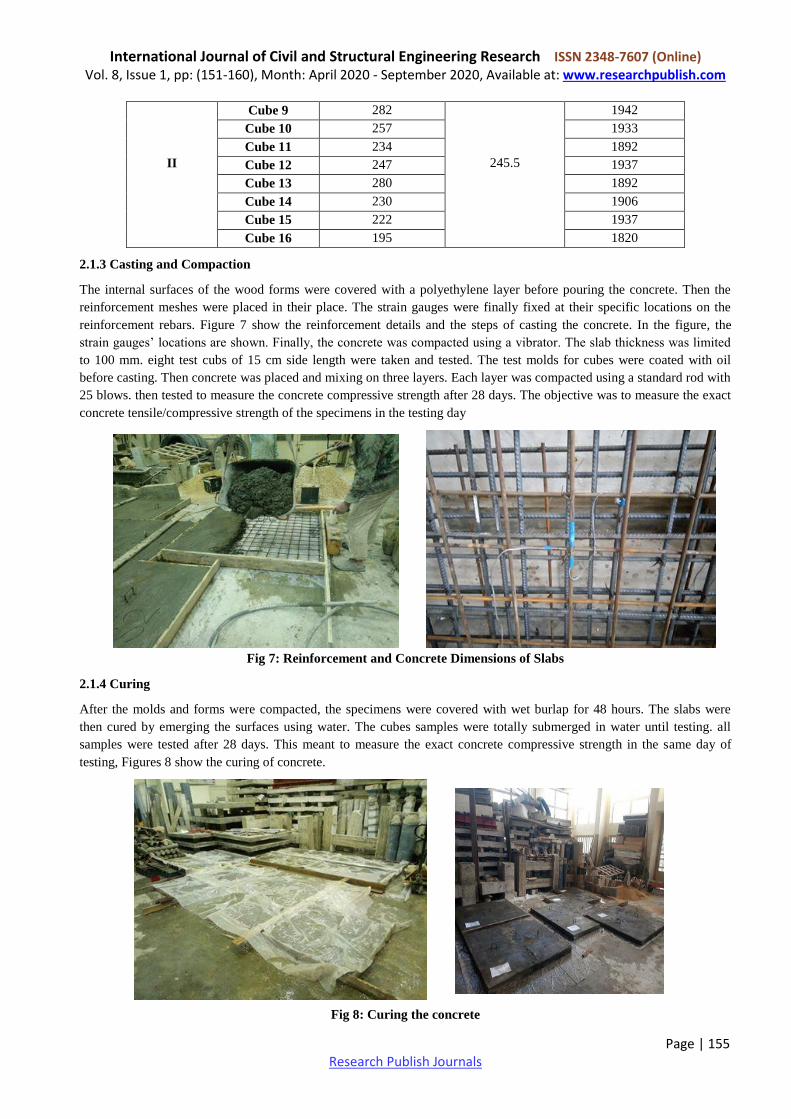
2.1.2 Light weight concrete Compressive Strength
Light weight concrete cubes (15x15x15 cm) were tested in the laboratory after 28 days using the compression universal
machine. The universal machine is shown in Figure 6. The average light weight concrete cubic compressive strength and
density of cubes are shown in Table (3) for different concrete batches to achieve properties of light weight concrete. From
the table, it was obvious that light weight concrete reach to compressive strength 250Kg/cm2 and density of it not
increase more than 2000 Kg/m3
Fig 6: Universal Machine and tested cubes
TABLE (3) : Test Result of Cube Strength.
Group
No.
Cube
No.
Strength
(Kg/cm2)
Average
Density (Kg/m3)
I
Cube 1 257
250.5
1946
Cube 2 245 1936
Cube 3 236 1966
Cube 4 280 1992
Cube 5 235 1983
Cube 6 256 1933
Cube 7 245 1922
Cube 8 250 1900
International Journal of Civil and Structural Engineering Research ISSN 2348-7607 (Online) Vol. 8, Issue 1, pp: (151-160), Month: April 2020 - September 2020, Available at: www.researchpublish.com
Page | 155 Research Publish Journals
II
Cube 9 282
245.5
1942
Cube 10 257 1933
Cube 11 234 1892
Cube 12 247 1937
Cube 13 280 1892
Cube 14 230 1906
Cube 15 222 1937
Cube 16 195 1820
2.1.3 Casting and Compaction
The internal surfaces of the wood forms were covered with a polyethylene layer before pouring the concrete. Then the
reinforcement meshes were placed in their place. The strain gauges were finally fixed at their specific locations on the
reinforcement rebars. Figure 7 show the reinforcement details and the steps of casting the concrete. In the figure, the
strain gauges’ locations are shown. Finally, the concrete was compacted using a vibrator. The slab thickness was limited
to 100 mm. eight test cubs of 15 cm side length were taken and tested. The test molds for cubes were coated with oil
before casting. Then concrete was placed and mixing on three layers. Each layer was compacted using a standard rod with
25 blows. then tested to measure the concrete compressive strength after 28 days. The objective was to measure the exact
concrete tensile/compressive strength of the specimens in the testing day
Fig 7: Reinforcement and Concrete Dimensions of Slabs
2.1.4 Curing
After the molds and forms were compacted, the specimens were covered with wet burlap for 48 hours. The slabs were
then cured by emerging the surfaces using water. The cubes samples were totally submerged in water until testing. all
samples were tested after 28 days. This meant to measure the exact concrete compressive strength in the same day of
testing, Figures 8 show the curing of concrete.
Fig 8: Curing the concrete
International Journal of Civil and Structural Engineering Research ISSN 2348-7607 (Online) Vol. 8, Issue 1, pp: (151-160), Month: April 2020 - September 2020, Available at: www.researchpublish.com
Page | 156 Research Publish Journals
2.2 Instruments
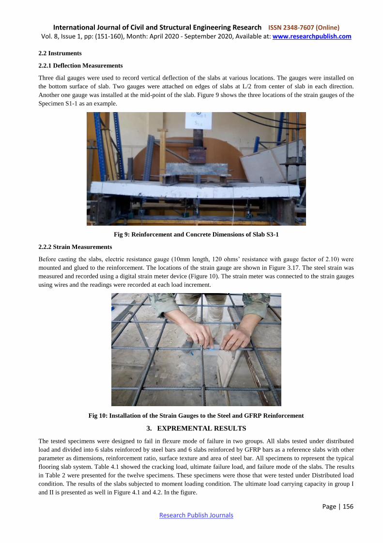
2.2.1 Deflection Measurements
Three dial gauges were used to record vertical deflection of the slabs at various locations. The gauges were installed on
the bottom surface of slab. Two gauges were attached on edges of slabs at L/2 from center of slab in each direction.
Another one gauge was installed at the mid-point of the slab. Figure 9 shows the three locations of the strain gauges of the
Specimen S1-1 as an example.
Fig 9: Reinforcement and Concrete Dimensions of Slab S3-1
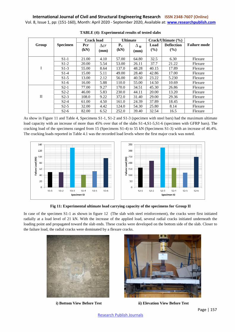
2.2.2 Strain Measurements
Before casting the slabs, electric resistance gauge (10mm length, 120 ohms’ resistance with gauge factor of 2.10) were
mounted and glued to the reinforcement. The locations of the strain gauge are shown in Figure 3.17. The steel strain was
measured and recorded using a digital strain meter device (Figure 10). The strain meter was connected to the strain gauges
using wires and the readings were recorded at each load increment.
Fig 10: Installation of the Strain Gauges to the Steel and GFRP Reinforcement
3. EXPREMENTAL RESULTS
The tested specimens were designed to fail in flexure mode of failure in two groups. All slabs tested under distributed
load and divided into 6 slabs reinforced by steel bars and 6 slabs reinforced by GFRP bars as a reference slabs with other
parameter as dimensions, reinforcement ratio, surface texture and area of steel bar. All specimens to represent the typical
flooring slab system. Table 4.1 showed the cracking load, ultimate failure load, and failure mode of the slabs. The results
in Table 2 were presented for the twelve specimens. These specimens were those that were tested under Distributed load
condition. The results of the slabs subjected to moment loading condition. The ultimate load carrying capacity in group I
and II is presented as well in Figure 4.1 and 4.2. In the figure.
International Journal of Civil and Structural Engineering Research ISSN 2348-7607 (Online) Vol. 8, Issue 1, pp: (151-160), Month: April 2020 - September 2020, Available at: www.researchpublish.com
Page | 157 Research Publish Journals
TABLE (4): Experimental results of tested slabs
Group
Specimen
Crack load Ultimate Crack/Ultimate (%)
Failure mode Pcr
(kN) cr
(mm)
PU
(kN) u
(mm)
Load
(%)
Deflection
(%)
I
S1-1 21.00 4.10 57.00 64.80 32.5 6.30 Flexure
S1-2 20.00 5.54 53.00 26.11 37.7 21.22 Flexure
S1-3 55.00 8.64 137.0 48.28 40.15 17.89 Flexure
S1-4 15.00 5.11 49.00 28.40 42.86 17.00 Flexure
S1-5 13.00 2.12 56.00 40.50 23.22 5.230 Flexure
S1-6 16.00 5.88 110.0 55.00 14.50 10.69 Flexure
II
S2-1 77.00 9.27 170.0 34.51 45.30 26.86 Flexure
S2-2 46.00 5.83 230.0 44.11 20.00 13.20 Flexure
S2-3 108.0 9.22 372.0 31.40 29.00 29.36 Flexure
S2-4 61.00 4.50 161.0 24.39 37.89 18.45 Flexure
S2-5 32.00 4.42 124.0 54.30 25.80 8.14 Flexure
S2-6 82.00 6.52 252.0 39.40 32.54 16.5 Flexure
As show in Figure 11 and Table 4, Specimens S1-1, S1-2 and S1-3 (specimen with steel bars) had the maximum ultimate
load capacity with an increase of more than 45% over that of the slabs S1-4,S1-5,S1-6 (specimen with GFRP bars). The
cracking load of the specimens ranged from 15 (Specimens S1-4) to 55 kN (Specimens S1-3) with an increase of 46.4%.
The cracking loads reported in Table 4.1 was the recorded load levels where the first major crack was noted.
Fig 11: Experimental ultimate load carrying capacity of the specimens for Group II
In case of the specimen S1-1 as shown in figure 12 (The slab with steel reinforcement), the cracks were first initiated
radially at a load level of 21 kN. With the increase of the applied load, several radial cracks initiated underneath the
loading point and propagated toward the slab ends. These cracks were developed on the bottom side of the slab. Closer to
the failure load, the radial cracks were dominated by a flexure cracks.
i) Bottom View Before Test ii) Elevation View Before Test
International Journal of Civil and Structural Engineering Research ISSN 2348-7607 (Online) Vol. 8, Issue 1, pp: (151-160), Month: April 2020 - September 2020, Available at: www.researchpublish.com
Page | 158 Research Publish Journals
i) Bottom View ii) Top View
Figure (12): Crack Pattern for Specimen S1-1 (Failure Load = 57KN)
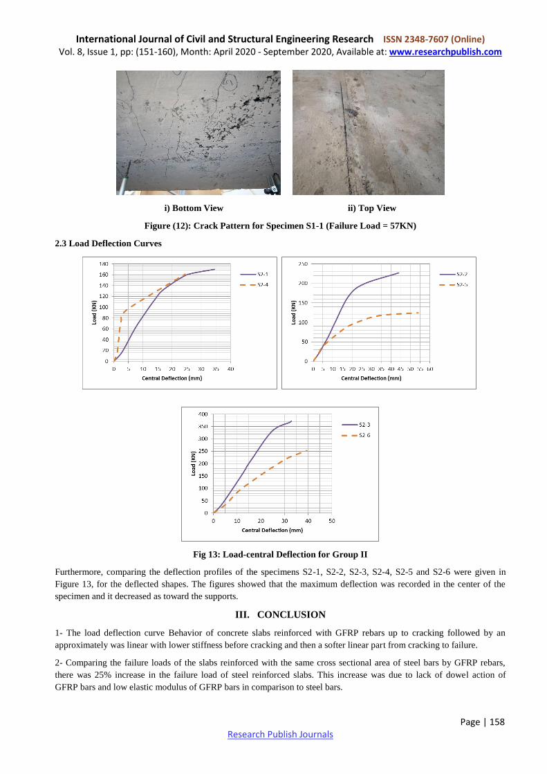
2.3 Load Deflection Curves
Fig 13: Load-central Deflection for Group II
Furthermore, comparing the deflection profiles of the specimens S2-1, S2-2, S2-3, S2-4, S2-5 and S2-6 were given in
Figure 13, for the deflected shapes. The figures showed that the maximum deflection was recorded in the center of the
specimen and it decreased as toward the supports.
III. CONCLUSION
1- The load deflection curve Behavior of concrete slabs reinforced with GFRP rebars up to cracking followed by an
approximately was linear with lower stiffness before cracking and then a softer linear part from cracking to failure.
2- Comparing the failure loads of the slabs reinforced with the same cross sectional area of steel bars by GFRP rebars,
there was 25% increase in the failure load of steel reinforced slabs. This increase was due to lack of dowel action of
GFRP bars and low elastic modulus of GFRP bars in comparison to steel bars.
International Journal of Civil and Structural Engineering Research ISSN 2348-7607 (Online) Vol. 8, Issue 1, pp: (151-160), Month: April 2020 - September 2020, Available at: www.researchpublish.com
Page | 159 Research Publish Journals
3- The load deflection curve behavior of concrete slabs reinforced with GFRP rebars up to cracking followed by an
approximately was linear with lower stiffness before cracking and then a softer linear part from cracking to failure.
4- The stiffness of GFRP reinforced concrete slab was significantly lower than it for the steel sample reinforced with the
same area of reinforcement after cracking, consequently, larger crack, deflection and strains. Increasing the area of the
reinforcement of GFRP rebars.
5- Deflections of slabs reinforced with GFRP bars are significantly larger than slabs reinforced with conventional steel
bars there was 30% increase in the deflection of GFRP reinforced slabs. This due to the low elastic modulus of GFRP bars
in comparison to steel bars.
6- The result of this work, shows that light-weight concrete can be designed to meet the criteria of compressive strength of
load bearing concrete and suitable solution in construction. Besides, light-weight concrete has been identified as a suitable
material to replace the normal concrete. At the same time, the density of light-weight concrete can be designed and
controlled according to the ratio of the mixture used.
7- The change of bar diameter resulting in change the failure load and small difference in deflections. This due to the
change in the surface area of reinforcement.
REFERENCES
[1] Cosenza , E, Manfredi, G., and Realfonzo, R. (1997)," Behaviour and Modeling of Bond of FRP- Rebars to Concrete
", Journal of Composites for Construction, Vol .1, no. 2,pp. 40-51.
[2] Deitz. D. H, HarikI. E, and Gesund. H, (1999)"One-Way Slabs Reinforced with Glass Fiber Reinforced Polymer
Reinforcing Bars" Special Publication Volume: 188, P 279-286
[3] Dulude.C, Ahmed. F, El-Gamal.S, (2010) "Testing of Large Scale Two Way Slabs Reinforced with GFRP bars" The
5th international conference on FRP composite in civil Engineering, pp.287.
[4] Alkhrdaji, T., L. Ombres and A. Nanni, (2000) “Flexural Behavior and Design of One-Way Concrete Slabs
Reinforced with Deformed GFRP Bars,” Proc., 3rd Inter. Conf. on Advanced Composite Materials in Bridges and
Structures, Ottawa, Canada, J. Humar and A.G. Razaqpur, Editors, pp. 217-224.
[5] Nasser F. H., (2015). “Structural Behavior of Light Weight Concrete Slab Panels Reinforced with CFRP Bars.”
Ph.d. Thesis of Babylon University, Babylon. March, pp.202.
[6] Qusai S. A., (1995). “ Properties of Light Weight Concrete Made From Local Porcelenite Aggregate.” M.Sc. Thesis
University of Baghdad, Baghdad, April, pp.117.
[7] Abbasi, M.S.A., Baluch, M.H., Azad, A.K. and Abdel-Rahman. H.H..,(2008), “ Nonlinear Finite Element
Modelingof faluire Modes in Reinforced Concrete Slabs”, Journal of Computers and Structures, Vol.42, No. 5,pp.
815-823.
[8] American Concrete Institute (ACI) State-of-the-Art Report (1999),"Provisional Desing Recommendations for
Concrete Reinforced with FRP Rebar's "Draft document.
[9] Abd Elnaby, S.F. (1998), "State of the art report on the Use of fiber reinforced bolymers for reinforcing concrete
elements" State of the Art Report, Faculty of Engineering, Helwan University, September 1990, p.34
[10] Abdallah, H., El-Badry, M, and Riskalla, S.(1996),"Behavior of concrete slabs Reinforced by GFRP", Advanced
Composite Materials, State-of-the-Art Report, The First Middle East Workshop on the Structural Composite, Ain
Shams University by The Egyptian Society of Engineers. Sharm El-Sheikh. Egypt. June 1996, PP. 229-226.
[11] American Concrete Institute (ACI) State-of-the-Art Reporte (2006)."Fiber Reinforced plastic (FRP) Reinforced for
Concrete Structures, Report by ACI Committee.440.
[12] Benmokrane, B., Tighiouart B., Chaallal O., (1996) "Bond strength and load distribution of composite FRP rebars in
concrete" ACI Mater. J.1996;96(3):246-53.

International Journal of Civil and Structural Engineering Research ISSN 2348-7607 (Online) Vol. 8, Issue 1, pp: (151-160), Month: April 2020 - September 2020, Available at: www.researchpublish.com
Page | 160 Research Publish Journals
[13] Benmokrane, B. and Masmoudi, R.(1996), "FRP C-bar Reinforcing Rod for concrete Structures", Advanced
Composite Materials in Bridges and Sturctures (ACMBS-I1), proceedings of the 2nd International Conference,
Montreal, Quebec, Canada, pp.181-188.
[14] Benmokrane B., Chaallalt O. And Masmoudi R., (2005) "Glass Fiber Reinforced Plastic (GFRP) Rebars for
Concrete Structures" Construction and Building Materials, Vol. 9, No. 6, pp. 353-364.
[15] Bedard, Claude (1992), "Composite Reinforcing Bars: Assessing Their Use in Construction" Concrete International,
Vo1.14, no.1, pp.55-59.
[16] Consenza, E., Manfredi , G., and Realfonzo, R.(1996) ,"Il Calcolo Della Lunghezza di Anchoraggio per Barre in
plastic Fribro- Rinforzata (FRP)", Proceedings of the 11th Congresso CTE, Napoli, 7-9Nov. 1996, pp.451-461.


![EC2 - Concrete Centre [Flat Slabs - 2007]](https://static.fdocuments.in/doc/165x107/551350094a7959b1478b45dc/ec2-concrete-centre-flat-slabs-2007.jpg)

![Concrete One-way Slabs - Timber design...Concrete One-way Slabs By using the [Concrete Member] design module linked to the [Analysis] design module, one-way slabs can be designed.](https://static.fdocuments.in/doc/165x107/6128234cdce56b427c583dcd/concrete-one-way-slabs-timber-design-concrete-one-way-slabs-by-using-the-concrete.jpg)