Behavior-Based Navigation System for a Service Robot...
6
Behavior-Based Navigation System for a Service Robot with a Mechatronic Head ⋆ Marco Negrete ∗ Jes´ us Savage ∗ Jes´ us Cruz ∗ Jaime M´ arquez ∗ ∗ Universidad Nacional Aut´onoma de M´ exico Abstract: In this paper a navigation system for a service robot based on a scheme of cooperative behaviors, which control a mobile base and a mechatronic head, is proposed. The main idea is to achieve a more cognitive control system through a strong interaction between base and head behaviors, perception and task planning. Some behaviors depend directly on the perception information and some others depend both on the task planning and perception, i.e. position control is improved by incorporating artificial intelligence techniques. A Kalman Filter is used for robot localization, nevertheless, since the filter is just a part of the behavior-based scheme, it is turned on and off conveniently according to the environment representation. The use of the mechatronic head improves significantly the navigation performance. Experimental results are presented to show the effectiveness of the scheme. Keywords: Mobile robots, autonomous vehicles, behavior-based robotics, navigation, localization. 1. INTRODUCTION In last years, research on navigation systems for mobile robots has been focused in achieving more cognitive sys- tems. For example Jae-Han et al. (2007) propose the use of a semantic map from which a path is planned and the localization of the robot is performed with an external sensor network, which is not desirable for service robots. Rawlinson and Jarvis (2008) developed a system that al- lows the robot to reach a goal through topological instruc- tions without the necessity of a previous map, nevertheless, since no information is stored, there is no learning. In Rogers et al. (2011) it is proposed to extract high-level characteristics of the objects in the environment in order to relate them with their semantic meaning. Weixing et al. (2012) propose a method to navigate by recognizing arrows and traffic signs. Arambula and Padilla (2011) improves the obstacle avoid- ance by incorporating a genetic algorithm for calculating the optimal potential field constants. Other related works, such as Palmeira et al. (2012) and Gonz´alez-Sarabia and Alvarado (2012) develop control laws for position or path tracking, nevertheless, they take odometry as the position measurement and this is not desirable for service robots, or they don’t present experimental results. These works proposed several methods to enhance a nav- igation system, nevertheless, none tested a complete sys- tem. In this paper, a navigation system for a service robot, Justina, is proposed. In section 2, the service robot Justina, in which all algorithms were tested, is described. Section 3 describes the navigation system: a highly interactive system composed by a path planner, a perception module, a set of behaviors controlling both the mobile base and the mechatronic head, and a localization subsystem containing ⋆ This work was partly supported by PAPIIT-DGAPA UNAM under Grant IN-107609 and by CONACYT a world representation and a Kalman filter for estimation. In section 4 some results are presented and discussed and finally, in section 5 conclusions and future work are given. 2. THE SERVICE ROBOT JUSTINA Fig. 1. The service robot Justina Justina is a service robot built at the Biorobotics Lab of the Engineer- ing School of the Na- tional University of Mex- ico. This robot and its predecessors have been participating in the Ro- cobup@Home league since 2006 performing several task like cleaning up a room, serving drinks and several other tasks that the human beings ask for. It is based on the ViRbot architecture for the operation of mobile robots (Savage et al., 1998). To accomplish all these tasks Justina needs a navigation system ca- pable to take her from one point to another in a safely manner and that means, with a safe ob- stacle avoidance, an efficient path planning and with a localization that allows her to know where she is in every moment. For sensing the environment, Justina counts with several sensors: two laser range finders, a Kinect sensor, a stereo camera and a directional microphone. Also, Justina has Memorias del XVI Congreso Latinoamericano de Control Automático, CLCA 2014 Octubre 14-17, 2014. Cancún, Quintana Roo, México 804
Transcript of Behavior-Based Navigation System for a Service Robot...
Behavior-Based Navigation System for aService Robot with a Mechatronic Head ⋆
Marco Negrete ∗ Jesus Savage ∗ Jesus Cruz ∗ Jaime Marquez ∗
∗ Universidad Nacional Autonoma de Mexico
Abstract: In this paper a navigation system for a service robot based on a scheme of cooperativebehaviors, which control a mobile base and a mechatronic head, is proposed. The main idea isto achieve a more cognitive control system through a strong interaction between base and headbehaviors, perception and task planning. Some behaviors depend directly on the perceptioninformation and some others depend both on the task planning and perception, i.e. positioncontrol is improved by incorporating artificial intelligence techniques. A Kalman Filter is usedfor robot localization, nevertheless, since the filter is just a part of the behavior-based scheme,it is turned on and off conveniently according to the environment representation. The use of themechatronic head improves significantly the navigation performance. Experimental results arepresented to show the effectiveness of the scheme.
Keywords: Mobile robots, autonomous vehicles, behavior-based robotics, navigation,localization.
1. INTRODUCTION
In last years, research on navigation systems for mobilerobots has been focused in achieving more cognitive sys-tems. For example Jae-Han et al. (2007) propose the useof a semantic map from which a path is planned and thelocalization of the robot is performed with an externalsensor network, which is not desirable for service robots.Rawlinson and Jarvis (2008) developed a system that al-lows the robot to reach a goal through topological instruc-tions without the necessity of a previous map, nevertheless,since no information is stored, there is no learning. InRogers et al. (2011) it is proposed to extract high-levelcharacteristics of the objects in the environment in orderto relate them with their semantic meaning. Weixing et al.(2012) propose a method to navigate by recognizing arrowsand traffic signs.
Arambula and Padilla (2011) improves the obstacle avoid-ance by incorporating a genetic algorithm for calculatingthe optimal potential field constants. Other related works,such as Palmeira et al. (2012) and Gonzalez-Sarabia andAlvarado (2012) develop control laws for position or pathtracking, nevertheless, they take odometry as the positionmeasurement and this is not desirable for service robots,or they don’t present experimental results.
These works proposed several methods to enhance a nav-igation system, nevertheless, none tested a complete sys-tem. In this paper, a navigation system for a service robot,Justina, is proposed. In section 2, the service robot Justina,in which all algorithms were tested, is described. Section3 describes the navigation system: a highly interactivesystem composed by a path planner, a perception module,a set of behaviors controlling both the mobile base and themechatronic head, and a localization subsystem containing
⋆ This work was partly supported by PAPIIT-DGAPA UNAMunder Grant IN-107609 and by CONACYT
a world representation and a Kalman filter for estimation.In section 4 some results are presented and discussed andfinally, in section 5 conclusions and future work are given.
2. THE SERVICE ROBOT JUSTINA
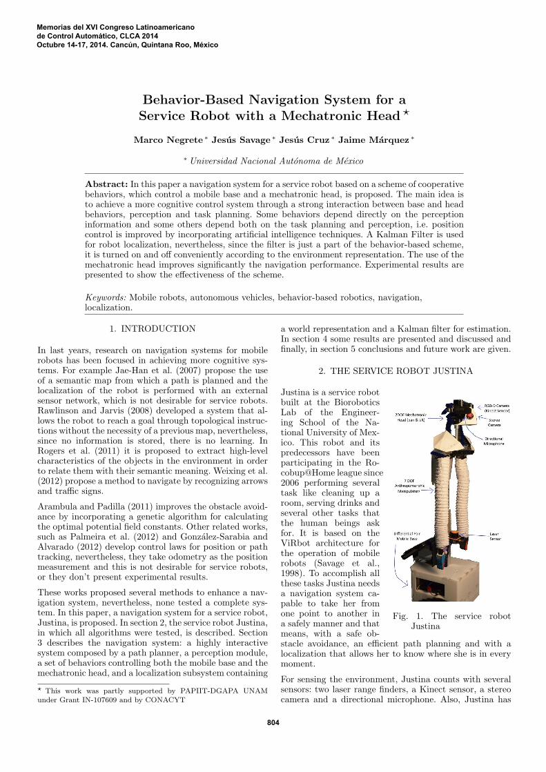
Fig. 1. The service robotJustina
Justina is a service robotbuilt at the BioroboticsLab of the Engineer-ing School of the Na-tional University of Mex-ico. This robot and itspredecessors have beenparticipating in the Ro-cobup@Home league since2006 performing severaltask like cleaning up aroom, serving drinks andseveral other tasks thatthe human beings askfor. It is based on theViRbot architecture forthe operation of mobilerobots (Savage et al.,1998). To accomplish allthese tasks Justina needsa navigation system ca-pable to take her fromone point to another ina safely manner and thatmeans, with a safe ob-stacle avoidance, an efficient path planning and with alocalization that allows her to know where she is in everymoment.
For sensing the environment, Justina counts with severalsensors: two laser range finders, a Kinect sensor, a stereocamera and a directional microphone. Also, Justina has
Memorias del XVI Congreso Latinoamericanode Control Automático, CLCA 2014Octubre 14-17, 2014. Cancún, Quintana Roo, México
804
TaskPlanner
PerceptionBase
Behaviors
HeadBehaviors
MobileBase
MechatronicHead
Localization
WorldRepresen-
tation
KalmanFilter
Sensors
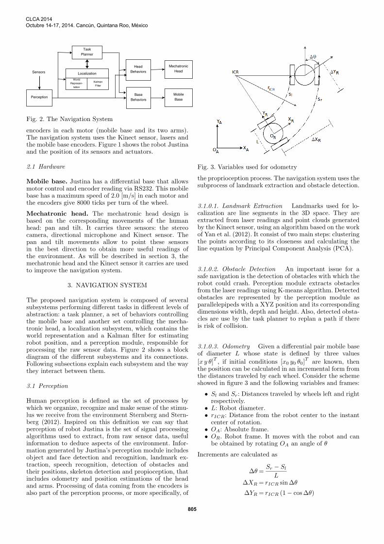
Fig. 2. The Navigation System
encoders in each motor (mobile base and its two arms).The navigation system uses the Kinect sensor, lasers andthe mobile base encoders. Figure 1 shows the robot Justinaand the position of its sensors and actuators.
2.1 Hardware
Mobile base. Justina has a differential base that allowsmotor control and encoder reading via RS232. This mobilebase has a maximum speed of 2.0 [m/s] in each motor andthe encoders give 8000 ticks per turn of the wheel.
Mechatronic head. The mechatronic head design isbased on the corresponding movements of the humanhead: pan and tilt. It carries three sensors: the stereocamera, directional microphone and Kinect sensor. Thepan and tilt movements allow to point these sensorsin the best direction to obtain more useful readings ofthe environment. As will be described in section 3, themechatronic head and the Kinect sensor it carries are usedto improve the navigation system.
3. NAVIGATION SYSTEM
The proposed navigation system is composed of severalsubsystems performing different tasks in different levels ofabstraction: a task planner, a set of behaviors controllingthe mobile base and another set controlling the mecha-tronic head, a localization subsystem, which contains theworld representation and a Kalman filter for estimatingrobot position, and a perception module, responsible forprocessing the raw sensor data. Figure 2 shows a blockdiagram of the different subsystems and its connections.Following subsections explain each subsystem and the waythey interact between them.
3.1 Perception
Human perception is defined as the set of processes bywhich we organize, recognize and make sense of the stimu-lus we receive from the environment Sternberg and Stern-berg (2012). Inspired on this definition we can say thatperception of robot Justina is the set of signal processingalgorithms used to extract, from raw sensor data, usefulinformation to deduce aspects of the environment. Infor-mation generated by Justina’s perception module includesobject and face detection and recognition, landmark ex-traction, speech recognition, detection of obstacles andtheir positions, skeleton detection and propioception, thatincludes odometry and position estimations of the headand arms. Processing of data coming from the encoders isalso part of the perception process, or more specifically, of
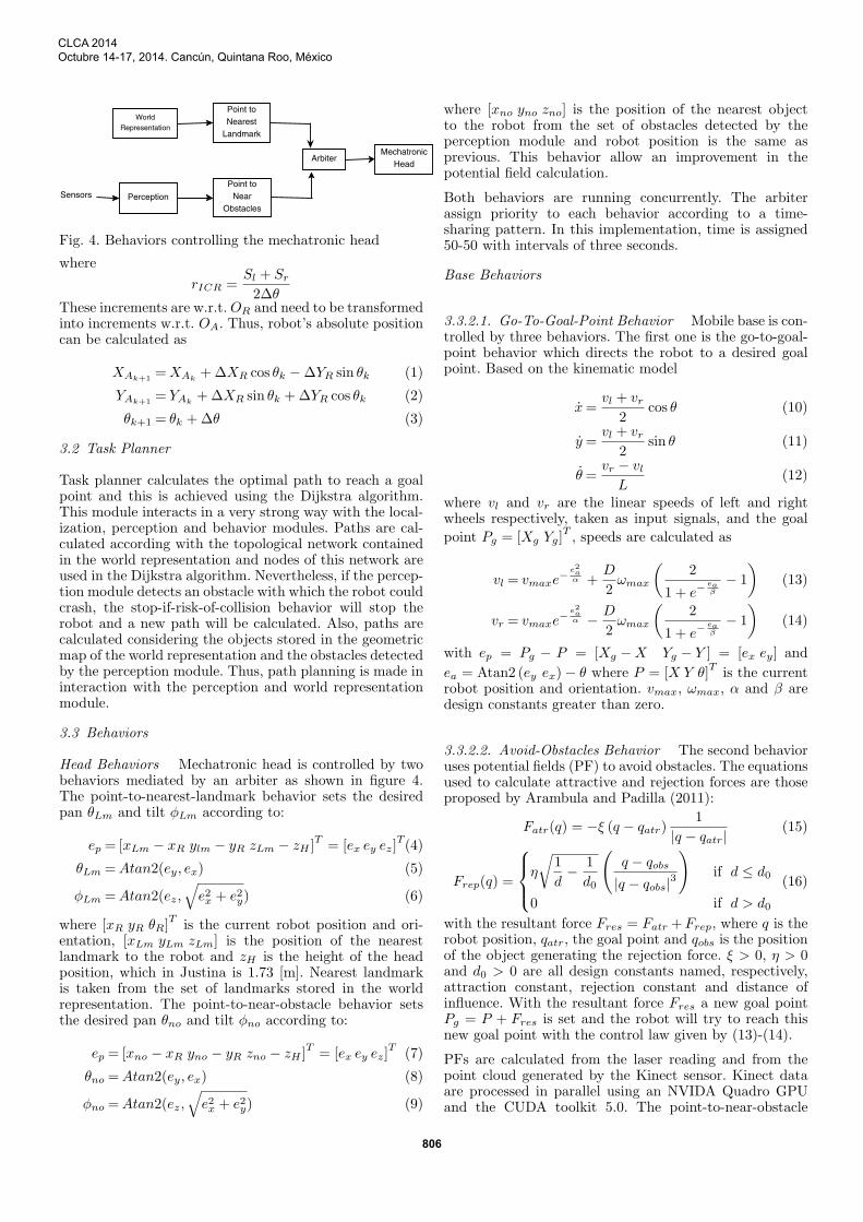
Fig. 3. Variables used for odometry
the proprioception process. The navigation system uses thesubprocess of landmark extraction and obstacle detection.
3.1.0.1. Landmark Extraction Landmarks used for lo-calization are line segments in the 3D space. They areextracted from laser readings and point clouds generatedby the Kinect sensor, using an algorithm based on the workof Yan et al. (2012). It consist of two main steps: clusteringthe points according to its closeness and calculating theline equation by Principal Component Analysis (PCA).
3.1.0.2. Obstacle Detection An important issue for asafe navigation is the detection of obstacles with which therobot could crash. Perception module extracts obstaclesfrom the laser readings using K-means algorithm. Detectedobstacles are represented by the perception module asparallelepipeds with a XYZ position and its correspondingdimensions width, depth and height. Also, detected obsta-cles are use by the task planner to replan a path if thereis risk of collision.
3.1.0.3. Odometry Given a differential pair mobile baseof diameter L whose state is defined by three values
[x y θ]T, if initial conditions [x0 y0 θ0]
Tare known, then
the position can be calculated in an incremental form fromthe distances traveled by each wheel. Consider the schemeshowed in figure 3 and the following variables and frames:
• Sl and Sr: Distances traveled by wheels left and rightrespectively.
• L: Robot diameter.• rICR: Distance from the robot center to the instantcenter of rotation.
• OA: Absolute frame.• OR. Robot frame. It moves with the robot and canbe obtained by rotating OA an angle of θ
Increments are calculated as
∆θ=Sr − Sl
L∆XR = rICR sin∆θ
∆YR = rICR (1− cos∆θ)
CLCA 2014Octubre 14-17, 2014. Cancún, Quintana Roo, México
805
WorldRepresentation
Point toNearest
Landmark
ArbiterMechatronic
Head
PerceptionSensorsPoint to
NearObstacles
Fig. 4. Behaviors controlling the mechatronic head
where
rICR =Sl + Sr
2∆θThese increments are w.r.t.OR and need to be transformedinto increments w.r.t. OA. Thus, robot’s absolute positioncan be calculated as
XAk+1=XAk
+∆XR cos θk −∆YR sin θk (1)
YAk+1= YAk
+∆XR sin θk +∆YR cos θk (2)
θk+1 = θk +∆θ (3)
3.2 Task Planner
Task planner calculates the optimal path to reach a goalpoint and this is achieved using the Dijkstra algorithm.This module interacts in a very strong way with the local-ization, perception and behavior modules. Paths are cal-culated according with the topological network containedin the world representation and nodes of this network areused in the Dijkstra algorithm. Nevertheless, if the percep-tion module detects an obstacle with which the robot couldcrash, the stop-if-risk-of-collision behavior will stop therobot and a new path will be calculated. Also, paths arecalculated considering the objects stored in the geometricmap of the world representation and the obstacles detectedby the perception module. Thus, path planning is made ininteraction with the perception and world representationmodule.
3.3 Behaviors
Head Behaviors Mechatronic head is controlled by twobehaviors mediated by an arbiter as shown in figure 4.The point-to-nearest-landmark behavior sets the desiredpan θLm and tilt ϕLm according to:
ep = [xLm − xR ylm − yR zLm − zH ]T= [ex ey ez]
T(4)
θLm =Atan2(ey, ex) (5)
ϕLm =Atan2(ez,√e2x + e2y) (6)
where [xR yR θR]T
is the current robot position and ori-entation, [xLm yLm zLm] is the position of the nearestlandmark to the robot and zH is the height of the headposition, which in Justina is 1.73 [m]. Nearest landmarkis taken from the set of landmarks stored in the worldrepresentation. The point-to-near-obstacle behavior setsthe desired pan θno and tilt ϕno according to:
ep = [xno − xR yno − yR zno − zH ]T= [ex ey ez]
T(7)
θno =Atan2(ey, ex) (8)
ϕno =Atan2(ez,√
e2x + e2y) (9)
where [xno yno zno] is the position of the nearest objectto the robot from the set of obstacles detected by theperception module and robot position is the same asprevious. This behavior allow an improvement in thepotential field calculation.
Both behaviors are running concurrently. The arbiterassign priority to each behavior according to a time-sharing pattern. In this implementation, time is assigned50-50 with intervals of three seconds.
Base Behaviors
3.3.2.1. Go-To-Goal-Point Behavior Mobile base is con-trolled by three behaviors. The first one is the go-to-goal-point behavior which directs the robot to a desired goalpoint. Based on the kinematic model
x=vl + vr
2cos θ (10)
y =vl + vr
2sin θ (11)
θ=vr − vl
L(12)
where vl and vr are the linear speeds of left and rightwheels respectively, taken as input signals, and the goal
point Pg = [Xg Yg]T, speeds are calculated as
vl = vmaxe− e2a
α +D
2ωmax
(2
1 + e−eaβ
− 1
)(13)
vr = vmaxe− e2a
α − D
2ωmax
(2
1 + e−eaβ
− 1
)(14)
with ep = Pg − P = [Xg −X Yg − Y ] = [ex ey] and
ea = Atan2 (ey ex)− θ where P = [X Y θ]Tis the current
robot position and orientation. vmax, ωmax, α and β aredesign constants greater than zero.
3.3.2.2. Avoid-Obstacles Behavior The second behavioruses potential fields (PF) to avoid obstacles. The equationsused to calculate attractive and rejection forces are thoseproposed by Arambula and Padilla (2011):
Fatr(q) = −ξ (q − qatr)1
|q − qatr|(15)
Frep(q) =
η
√1
d− 1
d0
(q − qobs
|q − qobs|3
)if d ≤ d0
0 if d > d0
(16)
with the resultant force Fres = Fatr +Frep, where q is therobot position, qatr, the goal point and qobs is the positionof the object generating the rejection force. ξ > 0, η > 0and d0 > 0 are all design constants named, respectively,attraction constant, rejection constant and distance ofinfluence. With the resultant force Fres a new goal pointPg = P + Fres is set and the robot will try to reach thisnew goal point with the control law given by (13)-(14).
PFs are calculated from the laser reading and from thepoint cloud generated by the Kinect sensor. Kinect dataare processed in parallel using an NVIDA Quadro GPUand the CUDA toolkit 5.0. The point-to-near-obstacle
CLCA 2014Octubre 14-17, 2014. Cancún, Quintana Roo, México
806
PathPlanner
Go ToGoal Point
Stop if Riskof Collision
AvoidObstacles
ArbiterMobileBase
PerceptionSensors
Fig. 5. Behaviors controlling the mobile base
behavior of the head helps to obtain a better view ofthe near obstacles. Figure 5 shows a block diagram of thebehaviors controlling the mobile base.
3.3.2.3. Stop-if-Risk-of-Collision Behavior Third be-havior stops the robot when a risk of collision is detected.Condition of risk is determined as follows: Let Pno be theposition of the nearest obstacle detected by the perceptionmodule, PR the current robot position and θR the currentrobot orientation. If
dc = |ep| < Kdr and
θc =Atan2(epy, epx)− θR < Kθr
with ep = Pno − PR, then there is a risk of collision. Withthe correct values ofKdr andKθr it is also possible to avoidlocal minima because, when a risk of collision is detected,a new path is calculated by the task planner.
3.4 Localization
World Representation Environment is represented sym-bolically through a topological network, a geometric mapand a map of landmarks. Topological network contains aset of nodes, each of which has a name and a list of nodeswith which is linked. The list of linked nodes is updatedevery time a new goal point is set in order to considerinformation about obstacles detected by perception mod-ule. This network is used for global path planning throughDijsktra algorithm. Path is taken as a global goal and eachnode is taken as a local goal which serves as goal point inthe go-to-goal-point behavior.
Geometric map contains a simple representation of theobjects in the environment as rectangles with an associatedposition and width-height values. Further, every object hassome ontological information like the object type (table,chair, desk) and a property indicating whether the objectis good for localization or not. Determining whether anobject is good for localization or not is made statistically.Good for localization indicates that lines can be easilyextracted. For example, a table or desk are objects thathave well defined lines (borders) while an office chairdoes not. In the localization process, this information isused to determine the best angle toward which the headshould be pointed in order to get the biggest confidence oflandmarks. This process is described in subsection 3.4.2.
Regions are defined similarly to map objects: by an XYcoordinates and width-depth-height values. For example,a region with a desk and a table in the surroundingscould be good to perform the localization algorithm, whileanother one with only chairs and more complex furniture
Observedline
Robot
d
d
d
d
p1
p2
n1
n2
PfLm P
fLo
PiLo
PiLm
KnownLandmark
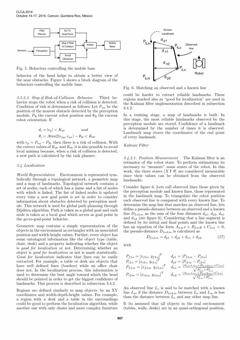
Fig. 6. Matching an observed and a known line
could be harder to extract reliable landmarks. Theseregions marked also as “good for localization” are used inthe Kalman filter implementation described in subsection3.4.2.
In a training stage, a map of landmarks is built. Inthis stage, the most reliable landmarks observed by theperception module are stored. Confidence of a landmarkis determined by the number of times it is observed.Landmark map stores the coordinates of the end pointof every landmark.
Kalman Filter
3.4.2.1. Position Measurement The Kalman filter is anestimator of the robot state. To perform estimations itsnecessary to “measure” some states of the robot. In thiswork, the three states [X Y θ] are considered measurablesince their values can be obtained from the observedlandmarks.
Consider figure 6. Lets call observed lines those given bythe perception module and known lines, those representedin the landmark map. To triangulate the robot positioneach observed line is compared with every known line. Todetermine the map line that matches an observed line, letsdefine a pseudo-distance between an observed and a knownline DLoLm as the sum of the four distances dp1, dp2, dn1and dn2 (see figure 6). Considering that a line segment isdefined by its initial and final points and the known linehas an equation of the form ALmx + BLmy + CLm = 0,the pseudo-distance DLoLm is calculated as
DLoLm = dp1 + dp2 + dn1 + dn2 (17)
with
PfLo = [xfLo yfLo]T
dp1 = |PfLm − PfLo|PiLo = [xiLo yiLo]
Tdp2 = |PiLm − PiLo|
PfLm = [xfLm yfLm]T
dn1 =|ALmxfLo+BLmyfLo+CLm|√
A2Lm
+B2Lm
PiLm = [xiLm yiLm]T
dn2 = |ALmxiLo+BLmyiLo+CLm|√A2
Lm+B2
Lm
An observed line Lo is said to be matched with a knownline Lm if the distance DLoLm between Lo and Lm is lessthan the distance between Lo and any other map line.
It its assumed that all objects in the real environment(tables, walls, desks) are in an quasi-orthogonal position,
CLCA 2014Octubre 14-17, 2014. Cancún, Quintana Roo, México
807
thus, it is expected that every observed line has an an-gle near to 0◦ or 90◦. An observed line Lo, with equa-tion ALox + BLoy + CLo = 0, is considered vertical if|BLo/ALo| < 0.6 and horizontal if |ALo/BLo| < 0.6. Ifthe observed line is not vertical nor horizontal, then it isconsidered as a wrong observation and is not taken intoaccount. For each pair Lm − Lo (map line, observed line)
a position error epm = [expm eypm eθpm]Tis calculated. If
Lo is vertical, the following equations are used:
expm = (xfLm − xfLo + xiLm − xiLo) /2 (18)
eypm = 0 (19)
eθpm = π/2− atan2 (ALo,−BLo) (20)
And, if Lo is horizontal:
expm = 0 (21)
eypm = (yfLm − yfLo + yiLm − yiLo) /2 (22)
eθpm =−atan2 (ALo,−BLo) (23)
Finally, an average error eav is obtained from all known-observed line pairs and PRm = PR + eav = Z is taken asthe measured position.
3.4.2.2. Extended Kalman Filter From (10)-(12) a dis-crete model can be obtained using an approximation ofthe derivatives.
xk+1 = xk +∆tvl + vr
2cos θk + ν1 (24)
yk+1 = yk +∆tvl + vr
2sin θk + ν2 (25)
θk+1 = θk +∆tvr − vil
L+ ν3 (26)
whereX = [x y θ] is the state vector, L the robot diameter,∆t the sampling step, vl and vr the left and right wheel
speeds respectively and ν = [ν1 ν2 ν3]T
is gaussian noisewithout temporal correlation, zero mean and covariancematrix Q.
While Justina is moving, it is trying to localize itself,but it does not search landmarks all the time. It onlyperforms the position estimation when it is in a “good-for-localization” (GFL) region (see section 3.4.1). Thishelps to reduce the uncertainty in the landmark extraction.Furthermore, the mechatronic head is always pointingto the nearest object marked as “good for localization”(GFL) thanks to the point-to-nearest-landmark behavior.Then, sometimes the measured position Z (see equation(3.4.2.1)) is the calculated from the observed lines andsometimes is the calculated from odometry. That is, themeasured state Z is given by
Z =
{Xlines if X is in a GFL region
Xodometry otherwise(27)
The observation model for the Kalman filter, consideringmeasurement noise, is given by Zk = Xk + ωk where ωk
is gaussian noise without temporal correlation, zero meanand covariance matrix R. The robot pose estimation bythe Extended Kalman Filter consist of the following steps:
Fig. 7. Biorobotics Lab, where the navigation system wastested
Prediction: Based on the kinematic model and the obser-vation model, the next state and the output are predictedconsidering that noise is equal to zero both in the transi-tion state model and the observation model:
X(k+1|k) = F (X(k|k), u(k))
Z(k+1|k) = X(k+1|k)
P(k+1|k) = J(k)P(k|k)JT(k) +Q
where P is the covariance matrix of the estimation errorand J is the Jacobian of the function F w.r.t. X.
Update: Based on the observation error and the estima-tion error covariance, the next estimated state is calculatedaccording to:
S(k+1) =H(k+1)P(k|k+1)HT(k+1) +R
K(k+1) = P(k+1|k)HT(k+1)S
−1(k+1)
X(k+1|k+1) = X(k+1|k) +K(k+1)
(Z(k+1) − Z(k+1|k)
)P(k+1|k+1) =
(I − P(k+1)H(k+1)
)P(k+1|k)
where H is the Jacobian of the observation model, whichin this case is the identity since it is considered that thewhole robot state is measured. Matrix K is known as theKalman gain.
In the prediction step, position estimation based on thekinematic model is not calculated by solving the differenceequations (24)-(26), but taking as predicted position thevalue given by the odometry. Actually, odometry is per sean estimation based on the kinematic model.
In the update state, measurements Z(k+1) are those deter-mined by landmarks or odometry, depending on whetherthe robot is in a good-for-localization region or not.
4. EXPERIMENTAL RESULTS
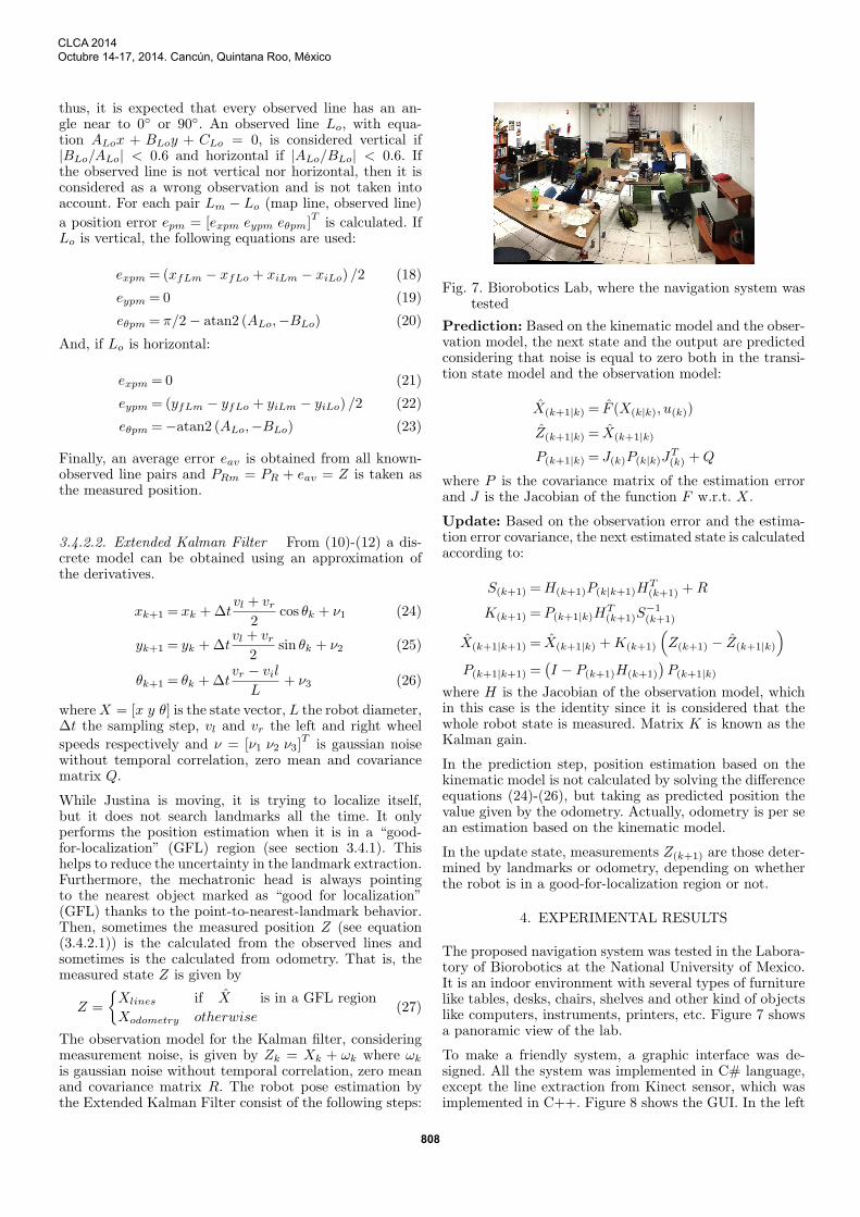
The proposed navigation system was tested in the Labora-tory of Biorobotics at the National University of Mexico.It is an indoor environment with several types of furniturelike tables, desks, chairs, shelves and other kind of objectslike computers, instruments, printers, etc. Figure 7 showsa panoramic view of the lab.
To make a friendly system, a graphic interface was de-signed. All the system was implemented in C# language,except the line extraction from Kinect sensor, which wasimplemented in C++. Figure 8 shows the GUI. In the left
CLCA 2014Octubre 14-17, 2014. Cancún, Quintana Roo, México
808
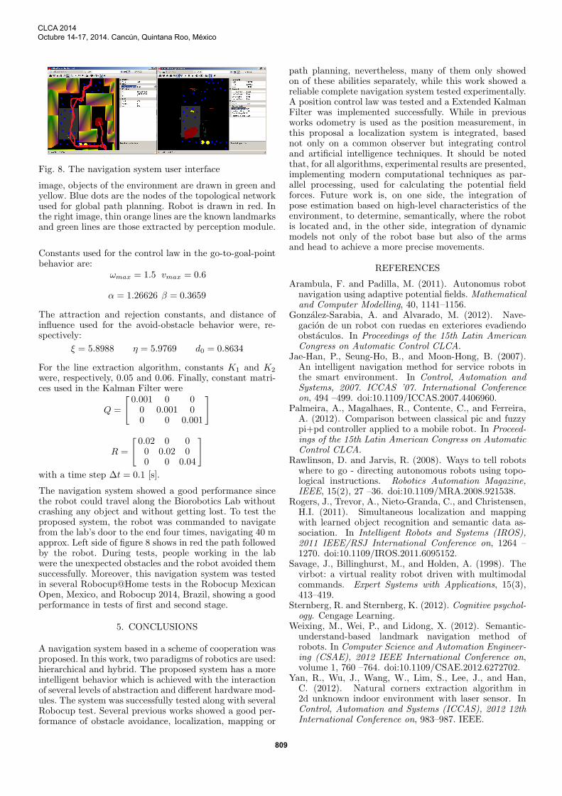
Fig. 8. The navigation system user interface
image, objects of the environment are drawn in green andyellow. Blue dots are the nodes of the topological networkused for global path planning. Robot is drawn in red. Inthe right image, thin orange lines are the known landmarksand green lines are those extracted by perception module.
Constants used for the control law in the go-to-goal-pointbehavior are:
ωmax = 1.5 vmax = 0.6
α = 1.26626 β = 0.3659
The attraction and rejection constants, and distance ofinfluence used for the avoid-obstacle behavior were, re-spectively:
ξ = 5.8988 η = 5.9769 d0 = 0.8634
For the line extraction algorithm, constants K1 and K2
were, respectively, 0.05 and 0.06. Finally, constant matri-ces used in the Kalman Filter were
Q =
[0.001 0 00 0.001 00 0 0.001
]
R =
[0.02 0 00 0.02 00 0 0.04
]with a time step ∆t = 0.1 [s].
The navigation system showed a good performance sincethe robot could travel along the Biorobotics Lab withoutcrashing any object and without getting lost. To test theproposed system, the robot was commanded to navigatefrom the lab’s door to the end four times, navigating 40 mapprox. Left side of figure 8 shows in red the path followedby the robot. During tests, people working in the labwere the unexpected obstacles and the robot avoided themsuccessfully. Moreover, this navigation system was testedin several Robocup@Home tests in the Robocup MexicanOpen, Mexico, and Robocup 2014, Brazil, showing a goodperformance in tests of first and second stage.
5. CONCLUSIONS
A navigation system based in a scheme of cooperation wasproposed. In this work, two paradigms of robotics are used:hierarchical and hybrid. The proposed system has a moreintelligent behavior which is achieved with the interactionof several levels of abstraction and different hardware mod-ules. The system was successfully tested along with severalRobocup test. Several previous works showed a good per-formance of obstacle avoidance, localization, mapping or
path planning, nevertheless, many of them only showedon of these abilities separately, while this work showed areliable complete navigation system tested experimentally.A position control law was tested and a Extended KalmanFilter was implemented successfully. While in previousworks odometry is used as the position measurement, inthis proposal a localization system is integrated, basednot only on a common observer but integrating controland artificial intelligence techniques. It should be notedthat, for all algorithms, experimental results are presented,implementing modern computational techniques as par-allel processing, used for calculating the potential fieldforces. Future work is, on one side, the integration ofpose estimation based on high-level characteristics of theenvironment, to determine, semantically, where the robotis located and, in the other side, integration of dynamicmodels not only of the robot base but also of the armsand head to achieve a more precise movements.
REFERENCES
Arambula, F. and Padilla, M. (2011). Autonomus robotnavigation using adaptive potential fields. Mathematicaland Computer Modelling, 40, 1141–1156.
Gonzalez-Sarabia, A. and Alvarado, M. (2012). Nave-gacion de un robot con ruedas en exteriores evadiendoobstaculos. In Proceedings of the 15th Latin AmericanCongress on Automatic Control CLCA.
Jae-Han, P., Seung-Ho, B., and Moon-Hong, B. (2007).An intelligent navigation method for service robots inthe smart environment. In Control, Automation andSystems, 2007. ICCAS ’07. International Conferenceon, 494 –499. doi:10.1109/ICCAS.2007.4406960.
Palmeira, A., Magalhaes, R., Contente, C., and Ferreira,A. (2012). Comparison between classical pic and fuzzypi+pd controller applied to a mobile robot. In Proceed-ings of the 15th Latin American Congress on AutomaticControl CLCA.
Rawlinson, D. and Jarvis, R. (2008). Ways to tell robotswhere to go - directing autonomous robots using topo-logical instructions. Robotics Automation Magazine,IEEE, 15(2), 27 –36. doi:10.1109/MRA.2008.921538.
Rogers, J., Trevor, A., Nieto-Granda, C., and Christensen,H.I. (2011). Simultaneous localization and mappingwith learned object recognition and semantic data as-sociation. In Intelligent Robots and Systems (IROS),2011 IEEE/RSJ International Conference on, 1264 –1270. doi:10.1109/IROS.2011.6095152.
Savage, J., Billinghurst, M., and Holden, A. (1998). Thevirbot: a virtual reality robot driven with multimodalcommands. Expert Systems with Applications, 15(3),413–419.
Sternberg, R. and Sternberg, K. (2012). Cognitive psychol-ogy. Cengage Learning.
Weixing, M., Wei, P., and Lidong, X. (2012). Semantic-understand-based landmark navigation method ofrobots. In Computer Science and Automation Engineer-ing (CSAE), 2012 IEEE International Conference on,volume 1, 760 –764. doi:10.1109/CSAE.2012.6272702.
Yan, R., Wu, J., Wang, W., Lim, S., Lee, J., and Han,C. (2012). Natural corners extraction algorithm in2d unknown indoor environment with laser sensor. InControl, Automation and Systems (ICCAS), 2012 12thInternational Conference on, 983–987. IEEE.
CLCA 2014Octubre 14-17, 2014. Cancún, Quintana Roo, México
809