Beginning DirectX 11 Game Programming
385
-
Upload
wendy-jones -
Category
Documents
-
view
1.099 -
download
280
Transcript of Beginning DirectX 11 Game Programming

Beginning
DirectX�R
11
Game Programming
Allen Sherrod and
Wendy Jones
Course Technology PTR
A part of Cengage Learning
Australia . Brazil . Japan . Korea . Mexico . Singapore . Spain . United Kingdom . United States

Beginning DirectX111 Game Programming
Allen Sherrod and Wendy Jones
Publisher and General Manager,
Course Technology PTR: Stacy L. Hiquet
Associate Director of Marketing:
Sarah Panella
Manager of Editorial Services:
Heather Talbot
Marketing Manager: Jordan Castellani
Senior Acquisitions Editor: Emi Smith
Project Editor: Dan Foster, Scribe Tribe
Technical Reviewer: Wendy Jones
Interior Layout Tech: MPS Limited,
a Macmillan Company
Cover Designer: Mike Tanamachi
Indexer: Valerie Haynes Perry
Proofreader: Gene Redding
© 2012 Course Technology, a part of Cengage Learning.
ALL RIGHTS RESERVED. No part of this work covered by the copyright
herein may be reproduced, transmitted, stored, or used in any form or
by any means graphic, electronic, or mechanical, including but not
limited to photocopying, recording, scanning, digitizing, taping, Web
distribution, information networks, or information storage and retrieval
systems, except as permitted under Section 107 or 108 of the 1976
United States Copyright Act, without the prior written permission of the
publisher.
For product information and technology assistance, contact us at
Cengage Learning Customer & Sales Support, 1-800-354-9706
For permission to use material from this text or product,
submit all requests online at www.cengage.com/permissions
Further permissions questions can be emailed to
DirectX is a registered trademark of Microsoft Corporation in the United
States and/or other countries.
All other trademarks are the property of their respective owners.
All images �C Cengage Learning unless otherwise noted.
Library of Congress Control Number: 2011920246
ISBN-13: 978-1-4354-5895-6
ISBN-10: 1-4354-5895-8
Course Technology, a part of Cengage Learning
20 Channel Center Street
Boston, MA 02210
USA
Cengage Learning is a leading provider of customized learning solutions
with office locations around the globe, including Singapore, the United
Kingdom, Australia, Mexico, Brazil, and Japan. Locate your local office at:
international.cengage.com/region
Cengage Learning products are represented in Canada by Nelson
Education, Ltd.
For your lifelong learning solutions, visit courseptr.com
Visit our corporate website at cengage.com
Printed in the United States of America1 2 3 4 5 6 7 13 12 11
eISBN-10: 1-4354-5896-6

I would like to thank the men and women at Cengage Learning who helped makethis book possible. I would also like to thank Wendy Jones for all her hard workon the previous editions of the book. And I would like to give a special thanks toEmi Smith, who has been very patient and helpful with this whole process.
—Allen Sherrod
Thanks to Allen Sherrod for taking over the writing duties for the DirectX 11version of this book. I truly appreciate all the hard work and research he’s put intoit. I’d also like to thank Emi Smith for giving me the opportunity to work withCengage Learning on multiple books.
—Wendy Jones
Acknowledgments

Allen Sherrod is an experienced author in the field of video game development.Allen’s past works include two editions of Ultimate Game Programming withDirectX, Ultimate 3D Game Engine Design and Architecture, Game GraphicsProgramming, and Data Structures and Algorithms for Game Developers. Allenhas also contributed to Game Developer magazine, the Game ProgrammingGems 6 book, and the Gamasutra.com website. Allen is the creator of www.UltimateGameProgramming.com.
Wendy Jones is co-founder and CTO of Kitty Code LLC, a games studio workingon mobile and console platforms such as iPhone, Windows Phone 7, and theXbox 360. Wendy’s past experience includes working on PC, console, and mobilegame titles while working with Atari and Electronic Arts. Wendy also teachesDirectX at Full Sail University and is department chair of the interactivedevelopment department. Wendy can be reached through her website at www.fasterkittycodecode.com.
About the Authors

Introduction . . . . . . . . . . . . . . . . . . . . . . . . . . . . . . . . . . . . . . . . . . . xi
Chapter 1 The What, Why, and How of DirectX . . . . . . . . . . . . . . . . 1
What Is DirectX? . . . . . . . . . . . . . . . . . . . . . . . . . . . . . . . . . . . . . . . 1
DirectX 10 versus DirectX 9 . . . . . . . . . . . . . . . . . . . . . . . . . . . . . 2
DirectX 11 versus DirectX 10 . . . . . . . . . . . . . . . . . . . . . . . . . . . . 4
DirectX 11 versus OpenGL 4.0 . . . . . . . . . . . . . . . . . . . . . . . . . . . 5
Why Is DirectX Needed? . . . . . . . . . . . . . . . . . . . . . . . . . . . . . . . . . . 6
How DirectX Is Put Together . . . . . . . . . . . . . . . . . . . . . . . . . . . . . . 7
The Components of DirectX 11 . . . . . . . . . . . . . . . . . . . . . . . . . . 7
Obsolete DirectX Components . . . . . . . . . . . . . . . . . . . . . . . . . . 10
Introducing Direct3D 11 . . . . . . . . . . . . . . . . . . . . . . . . . . . . . . . . . 12
Stages of Direct3D 11 . . . . . . . . . . . . . . . . . . . . . . . . . . . . . . . . 12
Direct3D 11 Considerations . . . . . . . . . . . . . . . . . . . . . . . . . . . . . . 15
DirectX Tools . . . . . . . . . . . . . . . . . . . . . . . . . . . . . . . . . . . . . . . . . 16
Sample Browser and Documentation . . . . . . . . . . . . . . . . . . . . . 16
PIX . . . . . . . . . . . . . . . . . . . . . . . . . . . . . . . . . . . . . . . . . . . . . . 16
Caps Viewer . . . . . . . . . . . . . . . . . . . . . . . . . . . . . . . . . . . . . . . 17
Diagnostic Tools . . . . . . . . . . . . . . . . . . . . . . . . . . . . . . . . . . . . 17
Texture Tool . . . . . . . . . . . . . . . . . . . . . . . . . . . . . . . . . . . . . . . 18
Error Lookup . . . . . . . . . . . . . . . . . . . . . . . . . . . . . . . . . . . . . . 19
Control Panel . . . . . . . . . . . . . . . . . . . . . . . . . . . . . . . . . . . . . . 20
Cross-Platform Audio Creation Tool . . . . . . . . . . . . . . . . . . . . . . 20
Contents
v

Game Definition File Editor . . . . . . . . . . . . . . . . . . . . . . . . . . . . 20
Down-Level Hardware . . . . . . . . . . . . . . . . . . . . . . . . . . . . . . . . 21
Summary . . . . . . . . . . . . . . . . . . . . . . . . . . . . . . . . . . . . . . . . . . . . 23
Chapter Questions . . . . . . . . . . . . . . . . . . . . . . . . . . . . . . . . . . . . . 23
Chapter 2 Your First DirectX Program . . . . . . . . . . . . . . . . . . . . . . . 27
Creating the Project . . . . . . . . . . . . . . . . . . . . . . . . . . . . . . . . . . . . 27
Adding Windows Code . . . . . . . . . . . . . . . . . . . . . . . . . . . . . . . . . 29
The Main Entry Point . . . . . . . . . . . . . . . . . . . . . . . . . . . . . . . . 30
Windows Initialization . . . . . . . . . . . . . . . . . . . . . . . . . . . . . . . . 32
Windows Callback Procedure . . . . . . . . . . . . . . . . . . . . . . . . . . . 42
Time for Direct3D . . . . . . . . . . . . . . . . . . . . . . . . . . . . . . . . . . . . . 44
Adding the DirectX Libraries . . . . . . . . . . . . . . . . . . . . . . . . . . . 45
Initializing Direct3D . . . . . . . . . . . . . . . . . . . . . . . . . . . . . . . . . 47
Driver Types and Features Levels . . . . . . . . . . . . . . . . . . . . . . . . 47
Device and Swap Chain Creation . . . . . . . . . . . . . . . . . . . . . . . . 49
Render Target View Creation . . . . . . . . . . . . . . . . . . . . . . . . . . 53
The Viewport . . . . . . . . . . . . . . . . . . . . . . . . . . . . . . . . . . . . . . 55
Clearing and Displaying the Screen . . . . . . . . . . . . . . . . . . . . . . 56
Cleaning Up . . . . . . . . . . . . . . . . . . . . . . . . . . . . . . . . . . . . . . . 58
Formats . . . . . . . . . . . . . . . . . . . . . . . . . . . . . . . . . . . . . . . . . . 58
The Blank D3D Window . . . . . . . . . . . . . . . . . . . . . . . . . . . . . . . . . 59
Design of the Template Framework . . . . . . . . . . . . . . . . . . . . . . 60
The Direct3D Class . . . . . . . . . . . . . . . . . . . . . . . . . . . . . . . . . . 60
The Blank Window Demo Class . . . . . . . . . . . . . . . . . . . . . . . . . 67
Updating the Application Loop . . . . . . . . . . . . . . . . . . . . . . . . . 70
DirectX Error Handling Library . . . . . . . . . . . . . . . . . . . . . . . . . . . . 73
Error Handling Functions . . . . . . . . . . . . . . . . . . . . . . . . . . . . . . 73
Error Handling Macros . . . . . . . . . . . . . . . . . . . . . . . . . . . . . . . 75
Summary . . . . . . . . . . . . . . . . . . . . . . . . . . . . . . . . . . . . . . . . . . . . 75
Chapter Questions . . . . . . . . . . . . . . . . . . . . . . . . . . . . . . . . . . . . . 76
Chapter 3 2D Rendering . . . . . . . . . . . . . . . . . . . . . . . . . . . . . . . . . 79
2D Game Development . . . . . . . . . . . . . . . . . . . . . . . . . . . . . . . . . 80
Textures . . . . . . . . . . . . . . . . . . . . . . . . . . . . . . . . . . . . . . . . . . 81
Sprites . . . . . . . . . . . . . . . . . . . . . . . . . . . . . . . . . . . . . . . . . . . 84
2D Geometry . . . . . . . . . . . . . . . . . . . . . . . . . . . . . . . . . . . . . . . . . 86
What Is a Vertex? . . . . . . . . . . . . . . . . . . . . . . . . . . . . . . . . . . . 87
Definition of a Triangle . . . . . . . . . . . . . . . . . . . . . . . . . . . . . . . 91
vi Contents

Vertex Buffers . . . . . . . . . . . . . . . . . . . . . . . . . . . . . . . . . . . . . . 94
Input Layout . . . . . . . . . . . . . . . . . . . . . . . . . . . . . . . . . . . . . . . 97
Drawing a 2D Triangle . . . . . . . . . . . . . . . . . . . . . . . . . . . . . . 105
2D Triangle Demo . . . . . . . . . . . . . . . . . . . . . . . . . . . . . . . . . . . . 108
Loading the Geometry . . . . . . . . . . . . . . . . . . . . . . . . . . . . . . 108
Rendering the Geometry . . . . . . . . . . . . . . . . . . . . . . . . . . . . . 114
Texture Mapping . . . . . . . . . . . . . . . . . . . . . . . . . . . . . . . . . . . . . 116
Texture Interfaces . . . . . . . . . . . . . . . . . . . . . . . . . . . . . . . . . . 118
MIP Maps . . . . . . . . . . . . . . . . . . . . . . . . . . . . . . . . . . . . . . . . 119
Texture Details . . . . . . . . . . . . . . . . . . . . . . . . . . . . . . . . . . . . 121
Texture Mapping Demo . . . . . . . . . . . . . . . . . . . . . . . . . . . . . 122
Sprites . . . . . . . . . . . . . . . . . . . . . . . . . . . . . . . . . . . . . . . . . . . . . 133
Z-Ordering . . . . . . . . . . . . . . . . . . . . . . . . . . . . . . . . . . . . . . . 134
Sprite Image . . . . . . . . . . . . . . . . . . . . . . . . . . . . . . . . . . . . . . 135
Getting Sprites to the Screen . . . . . . . . . . . . . . . . . . . . . . . . . . 136
Positioning and Scaling Sprites . . . . . . . . . . . . . . . . . . . . . . . . 139
The Game Sprite Demo . . . . . . . . . . . . . . . . . . . . . . . . . . . . . . . . 140
Creating and Rendering the Game Sprite . . . . . . . . . . . . . . . . 143
Summary . . . . . . . . . . . . . . . . . . . . . . . . . . . . . . . . . . . . . . . . . . . 153
What You Have Learned . . . . . . . . . . . . . . . . . . . . . . . . . . . . . . . 153
Chapter Questions . . . . . . . . . . . . . . . . . . . . . . . . . . . . . . . . . . . . 153
On Your Own . . . . . . . . . . . . . . . . . . . . . . . . . . . . . . . . . . . . . . . 154
Chapter 4 Text and Font Rendering . . . . . . . . . . . . . . . . . . . . . . . . 155
Text in Games . . . . . . . . . . . . . . . . . . . . . . . . . . . . . . . . . . . . . . . 155
Adding Text . . . . . . . . . . . . . . . . . . . . . . . . . . . . . . . . . . . . . . . . . 158
Textured Fonts . . . . . . . . . . . . . . . . . . . . . . . . . . . . . . . . . . . . 159
A Font System Explained . . . . . . . . . . . . . . . . . . . . . . . . . . . . . 160
Creating a Font System Using Sprites . . . . . . . . . . . . . . . . . . . . . . 161
Advanced Topics . . . . . . . . . . . . . . . . . . . . . . . . . . . . . . . . . . . . . 171
In-Game Text Boxes . . . . . . . . . . . . . . . . . . . . . . . . . . . . . . . . 172
In-Game Console Window . . . . . . . . . . . . . . . . . . . . . . . . . . . . 172
Game Menus . . . . . . . . . . . . . . . . . . . . . . . . . . . . . . . . . . . . . 173
Heads-Up Display . . . . . . . . . . . . . . . . . . . . . . . . . . . . . . . . . . 174
Summary . . . . . . . . . . . . . . . . . . . . . . . . . . . . . . . . . . . . . . . . . . . 174
Chapter Questions . . . . . . . . . . . . . . . . . . . . . . . . . . . . . . . . . . . . 174
On Your Own . . . . . . . . . . . . . . . . . . . . . . . . . . . . . . . . . . . . . . . 176
Contents vii

Chapter 5 Input Detection and Response . . . . . . . . . . . . . . . . . . . . 177
I Need Input . . . . . . . . . . . . . . . . . . . . . . . . . . . . . . . . . . . . . . . . 177
Input Options . . . . . . . . . . . . . . . . . . . . . . . . . . . . . . . . . . . . . 179
Keyboard Input . . . . . . . . . . . . . . . . . . . . . . . . . . . . . . . . . . . . . . 180
Win32 Keyboard Input . . . . . . . . . . . . . . . . . . . . . . . . . . . . . . 180
DirectInput Keyboard Input . . . . . . . . . . . . . . . . . . . . . . . . . . . 183
DirectInput Keyboard Demo . . . . . . . . . . . . . . . . . . . . . . . . . . 198
Mouse Input . . . . . . . . . . . . . . . . . . . . . . . . . . . . . . . . . . . . . . . . 208
DirectInput Mouse Input . . . . . . . . . . . . . . . . . . . . . . . . . . . . . 209
XInput—Game Controllers . . . . . . . . . . . . . . . . . . . . . . . . . . . . . . 215
Setting Up XInput . . . . . . . . . . . . . . . . . . . . . . . . . . . . . . . . . . 216
Controller Vibrations . . . . . . . . . . . . . . . . . . . . . . . . . . . . . . . . 217
XInput for Input . . . . . . . . . . . . . . . . . . . . . . . . . . . . . . . . . . . 218
Controller Capabilities . . . . . . . . . . . . . . . . . . . . . . . . . . . . . . . 218
Battery Life . . . . . . . . . . . . . . . . . . . . . . . . . . . . . . . . . . . . . . . 219
Keystrokes . . . . . . . . . . . . . . . . . . . . . . . . . . . . . . . . . . . . . . . 220
Headset Sound . . . . . . . . . . . . . . . . . . . . . . . . . . . . . . . . . . . . 221
XInput Demo . . . . . . . . . . . . . . . . . . . . . . . . . . . . . . . . . . . . . 222
Summary . . . . . . . . . . . . . . . . . . . . . . . . . . . . . . . . . . . . . . . . . . . 225
What You Have Learned . . . . . . . . . . . . . . . . . . . . . . . . . . . . . . . 225
Chapter Questions . . . . . . . . . . . . . . . . . . . . . . . . . . . . . . . . . . . . 226
On Your Own . . . . . . . . . . . . . . . . . . . . . . . . . . . . . . . . . . . . . . . 226
Chapter 6 3D Primer . . . . . . . . . . . . . . . . . . . . . . . . . . . . . . . . . . . 227
XNA Math . . . . . . . . . . . . . . . . . . . . . . . . . . . . . . . . . . . . . . . . . . 228
Utilities . . . . . . . . . . . . . . . . . . . . . . . . . . . . . . . . . . . . . . . . . . . . 228
Points . . . . . . . . . . . . . . . . . . . . . . . . . . . . . . . . . . . . . . . . . . . . . 229
Vectors . . . . . . . . . . . . . . . . . . . . . . . . . . . . . . . . . . . . . . . . . . . . 229
Vector Arithmetic . . . . . . . . . . . . . . . . . . . . . . . . . . . . . . . . . . 233
Distance Between Vectors . . . . . . . . . . . . . . . . . . . . . . . . . . . . 234
Determining the Length of a Vector . . . . . . . . . . . . . . . . . . . . 235
Normalize a Vector . . . . . . . . . . . . . . . . . . . . . . . . . . . . . . . . . 236
Cross Product . . . . . . . . . . . . . . . . . . . . . . . . . . . . . . . . . . . . . 237
Dot Product . . . . . . . . . . . . . . . . . . . . . . . . . . . . . . . . . . . . . . 237
3D Space . . . . . . . . . . . . . . . . . . . . . . . . . . . . . . . . . . . . . . . . . . . 239
Coordinate Systems . . . . . . . . . . . . . . . . . . . . . . . . . . . . . . . . . 239
Transformations . . . . . . . . . . . . . . . . . . . . . . . . . . . . . . . . . . . 241
World Transformations . . . . . . . . . . . . . . . . . . . . . . . . . . . . . . 242
viii Contents
View Transformations . . . . . . . . . . . . . . . . . . . . . . . . . . . . . . . 243
Projection Transformations . . . . . . . . . . . . . . . . . . . . . . . . . . . 243
Transforming an Object . . . . . . . . . . . . . . . . . . . . . . . . . . . . . 244
Matrices . . . . . . . . . . . . . . . . . . . . . . . . . . . . . . . . . . . . . . . . . . . 246
The Identity Matrix . . . . . . . . . . . . . . . . . . . . . . . . . . . . . . . . . 247
Matrix Scaling . . . . . . . . . . . . . . . . . . . . . . . . . . . . . . . . . . . . . 248
Matrix Translation . . . . . . . . . . . . . . . . . . . . . . . . . . . . . . . . . . 249
Matrix Rotation . . . . . . . . . . . . . . . . . . . . . . . . . . . . . . . . . . . 249
Matrix Concatenation . . . . . . . . . . . . . . . . . . . . . . . . . . . . . . . 252
Cube Demo . . . . . . . . . . . . . . . . . . . . . . . . . . . . . . . . . . . . . . . . . 253
Additional XNA Math Topics . . . . . . . . . . . . . . . . . . . . . . . . . . . . 269
Compiler Directives . . . . . . . . . . . . . . . . . . . . . . . . . . . . . . . . . 269
Constants . . . . . . . . . . . . . . . . . . . . . . . . . . . . . . . . . . . . . . . . 270
Macros . . . . . . . . . . . . . . . . . . . . . . . . . . . . . . . . . . . . . . . . . . 272
Structures and Types . . . . . . . . . . . . . . . . . . . . . . . . . . . . . . . . 274
Additional Functions . . . . . . . . . . . . . . . . . . . . . . . . . . . . . . . . 279
Additional Math Structures and Topics . . . . . . . . . . . . . . . . . . . . . 283
Game Physics and Collision Detection . . . . . . . . . . . . . . . . . . . 283
Summary . . . . . . . . . . . . . . . . . . . . . . . . . . . . . . . . . . . . . . . . . . . 284
What You Have Learned . . . . . . . . . . . . . . . . . . . . . . . . . . . . . . . 284
Chapter Questions . . . . . . . . . . . . . . . . . . . . . . . . . . . . . . . . . . . . 285
Chapter 7 Shaders and Effects . . . . . . . . . . . . . . . . . . . . . . . . . . . . 287
Shaders in Direct3D . . . . . . . . . . . . . . . . . . . . . . . . . . . . . . . . . . . 287
History of Programmable Shaders . . . . . . . . . . . . . . . . . . . . . . 288
Effect Files . . . . . . . . . . . . . . . . . . . . . . . . . . . . . . . . . . . . . . . . . . 289
Effect File Layout . . . . . . . . . . . . . . . . . . . . . . . . . . . . . . . . . . 290
Loading an Effect File . . . . . . . . . . . . . . . . . . . . . . . . . . . . . . . 291
External Variables and Constant Buffers . . . . . . . . . . . . . . . . . 292
Input and Output Structures . . . . . . . . . . . . . . . . . . . . . . . . . . 293
Technique Blocks . . . . . . . . . . . . . . . . . . . . . . . . . . . . . . . . . . . 294
Rasterizer States . . . . . . . . . . . . . . . . . . . . . . . . . . . . . . . . . . . 296
High Level Shading Language . . . . . . . . . . . . . . . . . . . . . . . . . . . 298
Variable Types . . . . . . . . . . . . . . . . . . . . . . . . . . . . . . . . . . . . 298
Semantics . . . . . . . . . . . . . . . . . . . . . . . . . . . . . . . . . . . . . . . . 299
Function Declarations . . . . . . . . . . . . . . . . . . . . . . . . . . . . . . . 299
Vertex Shaders . . . . . . . . . . . . . . . . . . . . . . . . . . . . . . . . . . . . . . . 300
Contents ix
Pixel Shaders . . . . . . . . . . . . . . . . . . . . . . . . . . . . . . . . . . . . . . . . 301
Texture Color Inversion . . . . . . . . . . . . . . . . . . . . . . . . . . . . . . 301
Color Shifting . . . . . . . . . . . . . . . . . . . . . . . . . . . . . . . . . . . . . 309
Multitexturing . . . . . . . . . . . . . . . . . . . . . . . . . . . . . . . . . . . . 311
Geometry Shaders . . . . . . . . . . . . . . . . . . . . . . . . . . . . . . . . . . . . 314
Geometry Shader Function Declaration . . . . . . . . . . . . . . . . . . 316
The Geometry Shader Explained . . . . . . . . . . . . . . . . . . . . . . . 316
Introduction to Lighting . . . . . . . . . . . . . . . . . . . . . . . . . . . . . 317
Summary . . . . . . . . . . . . . . . . . . . . . . . . . . . . . . . . . . . . . . . . . . . 325
What You Have Learned . . . . . . . . . . . . . . . . . . . . . . . . . . . . . . . 325
Chapter Questions . . . . . . . . . . . . . . . . . . . . . . . . . . . . . . . . . . . . 325
On Your Own . . . . . . . . . . . . . . . . . . . . . . . . . . . . . . . . . . . . . . . 326
Chapter 8 Cameras and Models in Direct3D . . . . . . . . . . . . . . . . . . 327
Cameras in Direct3D . . . . . . . . . . . . . . . . . . . . . . . . . . . . . . . . . . 327
Look-At Camera Demo . . . . . . . . . . . . . . . . . . . . . . . . . . . . . . 328
Arc-Ball Camera Demo . . . . . . . . . . . . . . . . . . . . . . . . . . . . . . 334
Meshes and Models . . . . . . . . . . . . . . . . . . . . . . . . . . . . . . . . . . . 342
The OBJ File Format . . . . . . . . . . . . . . . . . . . . . . . . . . . . . . . . 342
Reading Tokens from a File . . . . . . . . . . . . . . . . . . . . . . . . . . . 344
Loading Meshes from OBJ Files . . . . . . . . . . . . . . . . . . . . . . . . 349
Advanced Topics . . . . . . . . . . . . . . . . . . . . . . . . . . . . . . . . . . . . . 356
Complex Cameras . . . . . . . . . . . . . . . . . . . . . . . . . . . . . . . . . . 357
3D Level Files . . . . . . . . . . . . . . . . . . . . . . . . . . . . . . . . . . . . . 360
Summary . . . . . . . . . . . . . . . . . . . . . . . . . . . . . . . . . . . . . . . . . . . 363
What You Have Learned . . . . . . . . . . . . . . . . . . . . . . . . . . . . . . . 363
Chapter Questions . . . . . . . . . . . . . . . . . . . . . . . . . . . . . . . . . . . . 363
Index . . . . . . . . . . . . . . . . . . . . . . . . . . . . . . . . . . . . . . . . . . . . . . . . . 365
x Contents
Many of us wish to create our own video games. For some, gaming is a hobby, andfor others it is something fun to participate in casually. But for the rest of us,gaming and the dream of making our own games is more like a passion. Chancesare, if you’ve purchased this book, you are looking to turn your desire and passioninto something you can play and share with others.
About This BookThis book is the follow-up edition to Wendy Jones’s Beginning DirectX 10 GameProgramming book. In this book, we teach you the basics of getting started withgame graphics using the latest iteration of Direct3D: Direct3D 11.
The goal of this book is to teach you the various aspects of DirectX 11. The targetaudience for this text is beginning/intermediate C++ programmers with little tono experience with DirectX. Although past DirectX or OpenGL experience can beuseful, it is not required.
When you reach the end of this book, you will have had enough experience withDirectX 11 that you should be able to exploremaking simple video games and demos.Ideally, you will work your way up to make complex games and demos until you findyourself able to complete and release (even if for free at first) your own PC games.
Recommended Knowledge
This book assumes you have knowledge and familiarity of the C++ programminglanguage. You are also assumed to have a comfortable working knowledge ofVisual Studio 2010 and have completed at least a high-school level of mathe-
Introduction
xi

matics. Since this book is centered on learning DirectX for the first time, knowingDirectX is, of course, not required for working through this book.
Throughout this book we use Visual Studio C++ 2010 Express, which can bedownloaded from Microsoft’s website at www.microsoft.com/express/Down-loads. We are also using the June 2010 DirectX SDK, which can be downloadedfrom http://msdn.microsoft.com/en-us/directx.
Although not required for this book, it is recommended to try Adobe Photoshopfor the creation of textures (www.adobe.com/products/photoshop/photo-shopextended/) and XSI Mod Tool 7.5 for the creation of 3D models and meshes(http://usa.autodesk.com).
Companion Website: Code and Bonus Content
Almost every chapter has code samples and demos that give you hands-onexercises of the topics discussed. To follow along, view, execute, or manipulatethese code samples, you will need the book’s accompanying code, which can bedownloaded from:
www.ultimategameprogramming.com/BeginningDirectX11/
or
www.courseptr.com/downloads
At either of these locations, you'll also findWeb-only bonus content, including a ninthchapter, “Conclusions,” Appendix A, “Chapter Answers” (which provides answers toall the end-of-chapter review questions), and Appendix B, “Audio in DirectX” (whichintroduces you to the various DirectX APIs, including XAudio2 and XACT3).
Errata
Sometimes there are errors that are not caught before the book is released or thatcan even arise due to outside circumstances that we could not anticipate. If youfind any errors or issues with the book, please be sure to submit them to thecompanion website at www.ultimategameprogramming.com/BeginningDX11.Also be sure to check the companion website to see if there are existing issues thatother readers have found that you might find useful to know.
Companion Website Downloads
You may download the companion Web site files from www.courseptr.com/downloads. Please note that you will be redirected to our Cengage Learning site.
xii Introduction
The What, Why, and How
of DirectX
Prior to DirectX, game makers were struggling with problems stemming fromhardware incompatibilities, making it almost impossible for everyone to enjoythe same games due to the sheer volume of hardware configurations that existed.As the industry faced the need for standardization, Microsoft introduced theWindows Game SDK for Windows 95, which became DirectX 1. DirectXprovided game makers with a single set of APIs that would almost guaranteecompatibility across different sets of PC hardware. Since DirectX’s release, thenumber of games running under Windows has increased dramatically. This isstill true almost 15 years later.
In this chapter:
n Understanding what DirectX is
n Why DirectX is useful
n How data flows through the Direct3D 11 pipeline
n What’s new for Direct3D 11
What Is DirectX?
DirectX, Microsoft’s collection of application programming interfaces (APIs), isdesigned to give developers a low-level interface to the PC hardware runningWindows-based operating systems. Each component provides access to different
Chapter 1
1

aspects of the hardware, including graphics, sound, GPU general purposecomputing, and input devices, all through a standard interface.
This ideology allows developers to write their games using standard APIswithout having to worry about the low-level interfacing with the different piecesof hardware a customer might have. Imagine the difficulty developers once facedby trying to write code paths for the many different hardware configurations aplayer might have. What if the player had a different input device? What about adifferent operating system—even an upgraded version like the differencebetween DOS and Windows 95? What about audio hardware and drivers?What about different types and models of graphics hardware?
Having one standard API that hardware manufacturers must adhere to is muchmore ideal than writing code paths for every possible device on the market,especially since newer devices released after a game has shipped could possiblynot be recognized by the game, whereas using a standard solves this issue.DirectX is a collection of APIs used primarily by video game developers toaddress this need for standardization on the Windows and Xbox platforms. It isup to the hardware manufacturers to provide the driver layer for their devices.
No t e
The Xbox 360 uses a variation of DirectX 9.
DirectX 10 versus DirectX 9
In 2006, DirectX 10 presented a major leap forward in the DirectX SDK. Usuallywhen discussing DirectX we are discussing Direct3D, which is the API withinDirectX that receives the most overhauls. Most other APIs in DirectX are eitherdeprecated (meaning they are up for removal and it’s recommended that newsoftware not use them), are the same or have minor changes, or have beenremoved completely from the SDK.
The Direct3D 10 API is very lightweight when compared to its predecessors, andthe API is much easier to use than past versions. In fact, early versions ofDirectX were notoriously difficult to learn and use, but Microsoft has madechanges and improvements to the API over many years. Direct3D 10 was notjust an upgrade but, in many respects, an API that started fresh. And it indeedfelt like a fresh start with the launch of Windows Vista, DirectX 10-class
2 Chapter 1 n The What, Why, and How of DirectX

hardware, and a powerful API that was being hyped by one of the mostinfluential software giants in the world.
The most apparent removal in Direct3D 10 was the fixed-function pipeline,which is essentially a set of rendering states and algorithms built into the APIthat allowed for the rendering of objects using common effects. The fixed-function pipeline was removed in favor of programmable shaders withingraphics hardware. Graphics shaders, which will be discussed throughout thisbook, are code written specifically to customize how the graphics hardwareprocesses geometry. Graphics shaders were first introduced in DirectX 8, butsince then graphics hardware and the Shader Models that they run have evolvedto a point where they have become the star of the API.
In Direct3D 9 we can render geometry, enable lighting by setting a fewproperties and rendering states, have the API transform our geometry, and soforth by calling a few Direct3D function calls. In Direct3D 10 we can do all ofthat ourselves and much more in shaders. The key thing for beginners to keep inmind if this is their first time learning graphics programming is that the fixed-function pipeline was limited to whatever was built into the API, whereasshaders allow us to create any effect, limited only by the frame-rate we deemdesirable in our games. Want lighting? Call a Direct3D function to enable it andset its properties (up to eight lights). Want to render surfaces with more thanone image? Just enable it. If, however, you wish to perform pixel-based motionblur and depth-of-field, you are out of luck using the fixed-function pipeline.
Often if the fixed-function pipeline does not explicitly support it and you are notusing shaders, you cannot create the effect you want. Although some codershave found tricks and workarounds to getting some effects created withoutshaders, it was often a very difficult and inefficient workaround. I rememberthese times well and do not miss them.
Today, if we want to perform bump mapping, we can write a pixel shader thattakes the light direction, performs a calculation using it and the pixel-levelsurface direction loaded from a special image known as a normal map, andcombine that with the shading of the final pixel’s color. In the days beforeshaders, or even when shaders were limited in the features they provided (suchas the dark ages of register combiners for early versions of OpenGL), this wasimpossible, and doing even simple effects like normal mapping back then was
What Is DirectX? 3
only made possible through inefficient and often poor-quality tricks andapproximations. Of course what is considered an easy effect to one persondepends on his experience level.
The leap from DirectX 9 to DirectX 10 was a huge one. DirectX 10 went throughtwo iterations as the market’s acceptance caught up.
DirectX 11 versus DirectX 10
Direct3D 11 builds upon Direct3D 10.1 to add a new set of features forrendering next-generation graphics. The new additions to DirectX 11 includethe following:
n General-purpose computing on the GPU using the new API DirectCompute
n True multi threaded rendering support
n New hardware tessellation
n Shader Model 5.0 and object-oriented programming concepts for shaders
n BC6 (sometimes called BC6H) and BC7 for texture compression of HDRand LDR images, respectively
n Increased texture resolution sizes
n And much more
No t e
An image resource applied to a shape’s surface is called a texture. Most often this refers to colorimages that are mapped to a surface to give it more detail.
DirectX 11 is more of an incremental update to DirectX 10.1 rather than themajor update DirectX 10 was to DirectX 9. Microsoft took a risk by startingfresh with Direct3D 10 and requiring not only new hardware but WindowsVista as a minimum requirement. That was a few years ago, and todayMicrosoft’s gamble is working out because not only is hardware supportwidespread, but also the majority of Windows users now are spanning WindowsVista and Windows 7. DirectX has always taken the future into consideration,and with the number of years it takes next-generation games to be developed,DirectX 11 will be very important to gaming for many years to come.
4 Chapter 1 n The What, Why, and How of DirectX

DirectX 11 versus OpenGL 4.0
OpenGL has long been considered a rival graphics API to Direct3D. OpenGLsupports platforms outside of Windows-based operating systems, such as Maccomputers, Linux OSs, Apple’s iPhone and iPad, Sony’s Playstation 3 (animplementation at least), and a variety of mobile devices such as cell phonesand PDAs, along with other platforms. Although the native device creation ofOpenGL can differ from one platform to another, the rest of the API isconsidered platform independent, not including the long history of hardware-specific extensions and features from competing entities within the OpenGLcamp. DirectX, on the other hand, is available on the various Windows OSs andthe Xbox game consoles. To be considered DirectX 10 or 11 compatible,hardware must adhere to a strict compatibility list, whereas prior to DirectX10 this was not always the case. In the case of OpenGL this often led to vendor-specific extensions that worked on limited hardware. Incompatibilities withinthe hardware market caused rework when trying to achieve the same result onall supported devices.
The whole Direct3D versus OpenGL debate can often seem like a religious one,but the fact is that for many years OpenGL has lagged behind Direct3D.Microsoft has done a great job evolving Direct3D and improving it throughoutthe years, but OpenGL has only lagged behind, not keeping its promises as eachnew version is released, and time and time again has suffered from the sameproblems of yesteryear. When OpenGL 3.0 was first announced, it was thoughtthat OpenGL would finally move back into a position to rival Direct3D.Unfortunately, the world of OpenGL has gone through its share of ups anddowns, both within the group behind it and with how the API stacked againstDirect3D, and Direct3D has continued to dominate.
OpenGL 4.0 catches up to many of the publicized features of DirectX 11, mostnotably through the support of general-purpose computing using OpenCL andtessellation, and is positioning itself to be a step closer to the promises that werenever delivered in the past, most notably with OpenGL 2.0 and OpenGL 3.0.Although OpenGL is not out of the race yet, it unfortunately needs a lot of workto not only truly rival DirectX but also to win back the hearts and minds ofmany of us who turned to Direct3D once OpenGL’s faults became toonumerous. Even if the API catches up, the graphics API race is a lot like highschool where the popular kid wins the election.
What Is DirectX? 5

Why Is DirectX Needed?
Before the release of the Windows operating system, developers were writinggames for DOS. This single-threaded, non-GUI operating system provideddevelopers with a direct path between their application code and the hardwareit was running on. This had both its advantages and problems. For instance,because there was a direct path between the game code and the hardware,developers could pull every ounce of power out of the machine, giving themcomplete control over how their game performed. The downside included theneed to either write directly to the hardware or use a variety of third-partylibraries for any hardware they wanted their game title to support, includingeven common hardware such as video and sound cards.
Video cards were especially confusing because not all video cards followed thesame standard. Even though most video cards supported a series of commonresolutions, developers were forced to access video memory directly. This madeeven drawing to the screen difficult. Developers were definitely looking for abetter and easier way.
When Windows 3.1 was released, it carried with it the same limitations thatDOS had. Since Windows ran on top of DOS, it severely limited the resourcesavailable to games and took away the direct access developers had enjoyed for solong. Most games written to support Windows at the time consisted mainly ofcard and board games, while most games continued to support DOS only.Microsoft released DX1 as a way of enticing developers to make games forWindows to prove that the OS wasn’t slow and move people away from DOS-based systems.
Microsoft’s release of Windows 95 didn’t eliminate any of these problems untilthe release of DirectX 1, also known as the Windows Games SDK. It gavedevelopers a single library to write to, placing a common layer between theirgame and the PC hardware; drawing graphics to the screen had just become awhole lot easier. The first version of DirectX still didn’t provide support for allthe hardware out there, but it was a great starting point in giving gamedevelopers what they had been waiting for. Over the years, there have beenmultiple releases of DirectX, each one improving and adding support for newtechnologies such as network play, streaming audio, and new kinds of input
6 Chapter 1 n The What, Why, and How of DirectX
devices. The latest version of DirectX includes Direct3D 11, which is compatiblewith Microsoft Windows Vista and Windows 7 operating systems.
How DirectX Is Put Together
DirectX is based on a collection of code libraries, each providing a common setof functionality needed for games and multimedia applications. To make surethat your game only has to link to the necessary functionality, DirectX isseparated into multiple components.
The Components of DirectX 11
The DirectX API is split into multiple components, each representing a differentaspect of the system. Each API can be used independently of one another,thereby allowing the addition of only the functionality your game requires. Inthe latest version of DirectX, some of the components were updated, such asDirect3D, while others are now being maintained at their previous levels byMicrosoft until their removal (if they are deprecated). The components withinDirectX can be upgraded individually as new functionality is required.
Direct2D
Direct2D is used for 2D graphics within Win32 applications. It is capable ofrendering high-performance vector graphics.
DirectWrite
DirectWrite is used for fonts and text rendering within a Direct2D application.
DXGI
The DirectX Graphics Infrastructure, also known as DXGI, is used for thecreation of Direct3D swap chains and the enumeration of device adapters.
Direct3D
Direct3D is used for all 3D graphics in DirectX. It is also the API that receivesthe most attention and updates. Throughout this book we will largely focus onDirect3D.
How DirectX Is Put Together 7

XAudio2
XAudio2 is a lower-level audio processing API that is part of the XDK (XboxDevelopment Kit) and, now, the DirectX SDK. XAudio2 is the replacement forDirectSound. The original XAudio was used on the first Xbox video game console.
XACT3
XACT3 is a higher-level audio processing API built on top of XAudio2. XACT3allows developers to use the Cross-Platform Audio Creation Tool to authorsounds in their applications. Developers would use XAudio2 if they needed low-level control of their audio system or if they wanted to build their own higher-level audio system similar to XACT3. XACT3, as discussed in Appendix B,“Audio in DirectX” from the companion website, is a powerful and incredibleeasy tool to use for game audio.
XInput
XInput is the input API for the XDK and the DirectX SDK and is used forprocessing of input from all Xbox 360 controllers. Essentially any controller youcan use with your Xbox 360 can be used with the PC, and XInput is the API youuse for working with these devices. These devices include not only Xboxgamepad controllers but also Rock Band and Guitar Hero instrument controllers(e.g., guitars, drums, and so forth), Big Button controllers (shipped with thegame Scene It), arcade sticks (e.g., the Tekken 6 arcade stick), and so much more.XInput is the replacement for DirectInput.
No t e
XAudio is the sound API used only on Xbox game consoles. XAudio2, its successor, can be used onboth Xbox game consoles and Windows-based PCs.
XNA Math
The new XNA Math is not an API but rather a math library that implementsoptimized math operations that are common to video games. XNA Math usesSIMD (Single Instruction Multiple Data) to perform multiple operations with asingle instruction call. The XNA Math library is available to the Xbox 360 and toWindows PCs. We’ll discuss game math in general as well as XNA Math in moredetail in Chapter 6.
8 Chapter 1 n The What, Why, and How of DirectX
No t e
XNA Game Studio is a game development tool built on top of DirectX that allows developers tocreate games for both the Xbox 360 and Windows PCs using C# and .NET. XNA Math is the nameof the math library in the new DirectX SDK and can be used outside of the XNA Game Studio. Youdo not need to download the XNA Game Studio SDK.
DirectCompute
DirectCompute is a new API added to DirectX 11 that allows for general-purpose multi threading computing using the GPU. The GPU has the ability toprocess many tasks in parallel, such as physics, video compression and decom-pression, audio processing, and much more. Not all tasks are suited for the GPU,but for those that are, the possibilities are tremendous.
For more information on DirectCompute, check out the book Game Develop-ment with Microsoft’s DirectCompute for Beginners.
DirectSetup
Once your game is complete, you’ll want to show it to others. DirectSetup givesyou the functionality to install the latest version of DirectX on the user’scomputer. It also has the ability to check the latest installed version of DirectX.
Windows Games Explorer
The Games Explorer is a feature of Windows Vista and Windows 7 that allowsdevelopers to present their games on those OSs. The Games Explorer handlesthings such as the game’s display, title, rating, description, region-specific boxart, content ratings (e.g., M for Mature, T for Teens, etc.), game statistics andnotifications, parental controls, and more. The DirectX SDK provides plenty ofinformation on how to use the Games Explorer for your own games and couldbe very useful when it comes time to ship a game. An example of the GamesExplorer can be seen in Figure 1.1.
DirectInput
DirectInput is an API for detecting input with keyboards, mice, and joysticks.Today XInput is used for all game controllers. For keyboards and mice we canuse Win32 functions or we can use DirectInput, which we’ll examine later in thebook in Chapter 5. According to the DirectX SDK, DirectInput will remain in itscurrent form until new technologies replace it.
How DirectX Is Put Together 9

Obsolete DirectX Components
The following components are either deprecated or removed from the DirectXSDK:
DirectDraw
Once used for 2D rendering, today we can use either Direct2D or Direct3D for2D graphics. DirectDraw was merged with Direct3D into what was calledDirectX Graphics in DirectX 8.
Figure 1.1
An example of the Games Explorer in Windows 7.
10 Chapter 1 n The What, Why, and How of DirectX
No t e
In previous versions of DirectX, 2D drawing functionality was provided by a component calledDirectDraw. Because DirectDraw is no longer being updated, you should perform all drawing usingDirect3D or Direct2D.
DirectPlay
DirectPlay was used for networking capabilities for online games. It was built ontop of the UDP protocol (User Datagram Protocol) and served as a higher-levelabstraction for network communication. Today the API has been removed andis no longer part of the DirectX SDK. DirectPlay was deprecated in favor ofGames for Windows Live on the PC and Xbox Live on Xbox consoles.
DirectShow
DirectShow was used for multimedia rendering and recording. This meantDirectShow was able to display video files in multiple common formats, provideDVD navigation, and much more. Today DirectShow is part of the WindowsSDK and is no longer part of the DirectX SDK. Alternatively, Windows Vistaand Windows 7 users can use Microsoft’s Media Foundations for media content,which is also part of the Windows SDK. This is useful for video games if theyneed to display CG cut-scenes and video files.
DirectMusic
DirectMusic is now a deprecated API from the DirectX 7 and earlier days forplaying audio content in applications. DirectMusic offers low-level access toaudio and hardware and has been a topic in DirectX books and tutorials formany years. Today we use XAudio2 (low-level) or XACT3 (high-level) for audioin games and media applications.
DirectSound
DirectSound is another deprecated audio API used to give low-level access todevelopers for their audio needs. XAudio2 is its replacement. We discuss audioin detail in Appendix B, “Audio in DirectX,” located on the companion website.
The Components Object Model
The DirectX API is based on the Component Object Model (COM). COMobjects consist of a collection of interfaces that expose methods that developers
How DirectX Is Put Together 11
use to access DirectX. COM objects are normal DLL files that have beenregistered with the system to provide support for specific hardware in themachine. For DirectX COM objects, registration happens during the installationof DirectX. While similar to Cþþ objects, COM objects require the use of aninterface to access the methods within them. This is actually an advantage overstandard objects because multiple versions of an interface can be present withina COM object, allowing for backward compatibility.
For instance, each version of DirectX included a new DirectDraw interfaceaccessible through the API, while still containing the previous version so as notto break existing code. Therefore, games created using DirectX 7 are able towork with DirectX 9. In other words, older games can be installed and playedusing the latest version of the DirectX runtime.
An additional advantage to COM objects is their ability to work with multiplelanguages, not just Cþþ. Developers can use Visual Basic, Cþþ, or C# and stilluse the same DirectX libraries. As Microsoft updates and adds new functionalityto DirectX, the version numbers of each updated component will increase. You’llfind that not all the included components exist at the same version level. Forinstance, DirectInput remains at version 8.0, while Direct3D is now at version 11.
Introducing Direct3D 11
The release of Windows 7 has brought with it the release of Direct3D 11.Direct3D 11 is compatible with Windows Vista and Windows 7, along withDirectX 10-class hardware. Certain features of DirectX 11, such as tessellationand Shader Model 5.0, require DirectX 11-class hardware. But most of the APIcan be used with DirectX 10-class hardware.
Stages of Direct3D 11
Direct3D is more than just an API; it’s a tool for transforming geometric shapesand images into a living, breathing world. Even though you can treat manypieces of Direct3D as a black box and not have to worry about the implemen-tation details, it is a good idea to understand at least an overview of how itworks.
Direct3D processes your scene in multiple stages, with each stage performing aspecific set of tasks resulting in a final image. These stages are known as Direct3D’srendering pipeline, and a screenshot of each can be seen in Figure 1.2.
12 Chapter 1 n The What, Why, and How of DirectX

The first stage of Direct3D’s pipeline, called the Input-Assembler (IA) stage, canbe thought of as the building-block stage. In this stage we set the geometry weare going to render along with the necessary information Direct3D needs toperform that task.
The second stage is the vertex shader (VS) stage. A vertex is a single point thatmakes up a shape, such as a triangle. In a vertex shader we can run code thatoperates on each vertex, much of which depends on the effect we are setting upfor. Shaders will be discussed more throughout this entire book. A vertex shaderalways takes a single vertex as input and outputs a single vertex. This vertex datawas supplied by the data set using the input assembler.
The third, fourth, and fifth stages are optional stages that deal with tessellation.Tessellation is an advanced topic that uses two new shaders to Direct3D calledthe hull and domain shaders. Hardware tessellation, in a nutshell, is the processof taking input geometry and increasing or decreasing its level of detail. Thisallows for very high polygonal models to be rendered in real time with polygoncounts in the hundreds of thousands or even the millions. By having thehardware create the detail of the geometry, the application only has to submit a
Figure 1.2
The stages of Direct3D 11.
Introducing Direct3D 11 13

small amount of data that defines the low-level model. This model can be in theform of patches, which is a 3D modeling. The hardware takes this low-levelmodel and makes it higher level. Subdividing polygons means to take a polygonand divide it into smaller pieces.
The hull shader takes its input from the output of the vertex shader, which isoperating on control points and data versus traditional vertices, and producesoutput control points for what are known as patches. The tessellation stage,which appears between the hull shader and domain shader stages, is a fixed-function stage that takes the output from the hull shader and subdivides the dataon hardware. The domain shader is responsible for generating the vertex of asubdivided point.
The sixth stage, the geometry shader (GS), is also an optional shader stage. If there isno tessellation being performed, the geometry shader stage occurs after the vertexshader stage. Geometry shaders operate on entire shapes such as triangles, whereasthe vertex shader operates on a single point of a shape. The geometry shader has theability to essentially create or destroy geometry as needed, which depends largely onthe effect you are trying to create. One common example of geometry shaders isgenerating shadowing geometry from a model by creating what is known as ashadow volume. Another example is the generation of particles used to create particleeffects such as rain or explosions by taking a list of points that act as the center of theparticles and generating polygons around them.
The seventh stage, the Rasterizer, has the job of determining what pixels are visiblethrough clipping and culling geometry (we’ll discuss this in Chapter 6), setting upthe pixel shaders, and determining how the pixel shaders will be invoked.
The eighth stage is the pixel shader (PS) stage. In the pixel shader stage, theshader receives the geometric data from all previous stages and is used to shadethe pixels (sometimes referred to as fragments) that comprise that shape. Theoutput of the pixel shader is a single color value that will be used by the finalstage to build the final image displayed to the screen. If there are no tessellationor geometry shaders, the pixel shader receives its input from the vertex shaderdirectly. The input to the pixel shader is technically interpolated data—that is,data that is generated between the points (vertices) of a shape. We’ll discuss thismore in the next chapter.
14 Chapter 1 n The What, Why, and How of DirectX
The final stage, the output merger (OM) stage, is where it all comes together.The OM takes all of the output pieces from the other stages of the pipeline andbuilds up the final image to send to the screen.
Direct3D 11 Considerations
Some of you may already be familiar with writing games using DirectX, and ifso, there are a few things you need to be aware of when converting your game tothe latest version of Direct3D. If updating from Direct3D 10 to Direct3D 11, theprocess is fairly straightforward, and most of the work will be to replaceDirect3D 10 calls with their Direct3D 11 equivalent. Direct3D 11 is more of asuperset of Direct3D 10 and 10.1, so there is not a lot that will need to be done.Going from Direct3D 9.0 to 11.0 is another story.
When coming to Direct3D 11 from Direct3D 9, the biggest change is theremoval of the fixed-function pipeline. Previously you could choose one of thedefault ways to process your 3D scene, and Direct3D would handle the clipping,lighting, and the shading. Today, with D3D10 and D3D11, all this functionalityneeds to be specifically handled using the programmable pipeline. Chapter 7 isabout shaders, and its purpose is to bring you fully up to speed with all that isincluded in Direct3D 11. Throughout the entire book we’ll be using shaders anddiscussing them as necessary before we reach the comprehensive discussion inChapter 7.
Another of the more major changes is the removal of the CAPS bits. In previousversions of Direct3D, you had to check the capabilities of the underlying videohardware to make sure that certain functionality like pixel shaders was availableto use. Now, any features not provided by the hardware are emulated by thesystem in software, ensuring you always have the full range of functionality toplay with. This will greatly simplify the initialization code for games usingD3D10. It is also much needed, since in the past some hardware vendorssupported only a subset of features, which caused issues when dealing withsupporting different pieces of hardware. To be considered DirectX 10- or 11-compatible today, hardware must strictly follow guidelines for compliance.
Direct3D 9.0 is close to having a completely different API. It is not possible to domassive copy and paste on function names like you could get away withchanging code from Direct3D 10.0 to 11.0. In this situation you’ll most likely
Direct3D 11 Considerations 15
be better off creating a new rendering layer for your game and working off thestrengths of Direct3D 11 instead of trying to do a line-by-line search andreplace.
DirectX Tools
The DirectX SDK contains a wealth of information and tools for many DirectX-related topics. The SDK itself should be explored by all developers using DirectXbecause there are tremendously well documented and well developed tools thataid in the learning and/or developing of DirectX applications. In this section wewill briefly take a look at some of the tools available in the DirectX SDK.
Sample Browser and Documentation
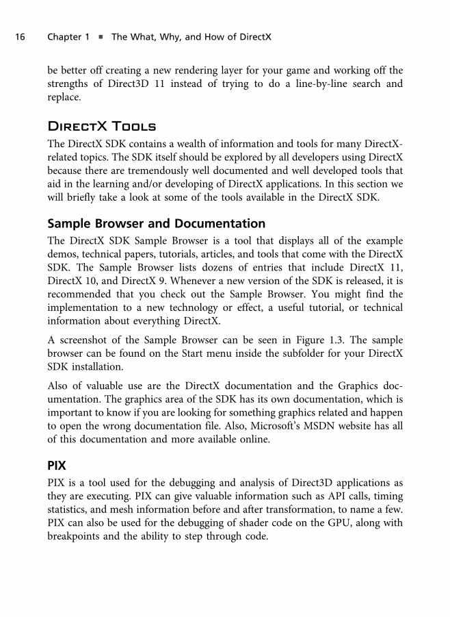
The DirectX SDK Sample Browser is a tool that displays all of the exampledemos, technical papers, tutorials, articles, and tools that come with the DirectXSDK. The Sample Browser lists dozens of entries that include DirectX 11,DirectX 10, and DirectX 9. Whenever a new version of the SDK is released, it isrecommended that you check out the Sample Browser. You might find theimplementation to a new technology or effect, a useful tutorial, or technicalinformation about everything DirectX.
A screenshot of the Sample Browser can be seen in Figure 1.3. The samplebrowser can be found on the Start menu inside the subfolder for your DirectXSDK installation.
Also of valuable use are the DirectX documentation and the Graphics doc-umentation. The graphics area of the SDK has its own documentation, which isimportant to know if you are looking for something graphics related and happento open the wrong documentation file. Also, Microsoft’s MSDN website has allof this documentation and more available online.
PIX
PIX is a tool used for the debugging and analysis of Direct3D applications asthey are executing. PIX can give valuable information such as API calls, timingstatistics, and mesh information before and after transformation, to name a few.PIX can also be used for the debugging of shader code on the GPU, along withbreakpoints and the ability to step through code.
16 Chapter 1 n The What, Why, and How of DirectX
Caps Viewer
The DirectX Caps Viewer shows information about the hardware’s capabilitiesby way of detailing its support for Direct3D, DirectDraw, DirectSound, andDirectInput. Every piece of information about what the hardware supports andits version are displayed by this tool. A screenshot of the Caps Viewer can beseen in Figure 1.4.
Diagnostic Tools
The DirectX Diagnostic tool is used to test various components of DirectX to seeif they are working properly. The diagnostic tool is used to create diagnostic
Figure 1.3
The DirectX SDK Sample Browser.
DirectX Tools 17

reports that can be saved to a file and/or sent to Microsoft. Sending the report toMicrosoft is done via the Report button on the More Help tab of the tool. If yoususpect some components are not working properly on a specific machine,running this tool can provide some insight.
Texture Tool
The DirectX Texture Tool is used to convert images to Direct3D texture formatsthat use DXTn compression. This tool is deprecated since it only supports
Figure 1.4
The Caps Viewer.
18 Chapter 1 n The What, Why, and How of DirectX

texture formats supported by DirectX 9, not DirectX 10 or 11. If you are lookingto create images compressed with DXT1 through DXT5, this tool can do the job.
No t e
BC6 and BC7 are the new formats not supported by this tool. The “BC” has replaced the “DXT” inthese compression formats.
The DirectX SDK also includes the Texture Converter. The Texture Converter isincluded with the TXVIEW.dll, which is installed as part of the DirectX SDKinstallation. The purpose of the Texture Converter is to convert an image fromone format to another. The file formats that can be seen include:
n BMP
n JPEG
n DDS
n TGA
n PNG
n DIB
n HDR
n PMF
The Texture Converter works by right-clicking on an image (or multiple images)in the Windows Explorer and selecting Convert to File Format from the drop-down list. Once the dialog box appears, set the properties of the image you areconverting by setting its output size, format, and output filename, to name a few.You could also use the texture conversion command-line tool called TexConv.exe or TexConvEx.exe for Direct3D 10 and 11 textures. The Texture Converterextension was last compatible with DirectX 9.
Error Lookup
The DirectX Error Lookup tool displays a description of any error code receivedwhile running your DirectX applications. You can enter the error code into thisapplication, hit the Lookup button, and it will describe the error to you. Not all
DirectX Tools 19

errors are clear, and this tool can be useful. The Error Lookup tool can be foundin the Utilities folder of your DirectX SDK installation.
Control Panel
The DirectX Control Panel, located in the Utilities folder of the DirectX SDK, isused to examine and modify the properties of various DirectX components.With the Control Panel tool you can do the following:
n Enable the debug layer of Direct3D 10/11
n Change the debug output level and settings for use during development
n View driver information
n View hardware support information
n View version information for the various components
Cross-Platform Audio Creation Tool
The Cross-Platform Audio Creation tool is a GUI tool (also available with theDirectX SDK is a command-line alternative) for creating audio files used byXACT3, which is DirectX’s high-level audio API/component. This tool is whatwe’ll use to take our audio clip files and organize them into various banks, aprocess that is discussed in more detail in Appendix B (online).
A screenshot of the Cross-Platform Audio Creation tool can be seen in Figure 1.5.The XACT3 tool can be used to create audio files for Windows PC and the Xbox360. For those doing game development using XNA, you can deploy a version ofthe audio files that matches the byte-ordering format of the processor within the360. Since the Xbox 360 uses an architecture based on PowerPC, the same outputfiles for the PC cannot be used interchangeably with the Xbox 360. This will notaffect us in this book since this book assumes game development on an x86processor using DirectX 11 on Windows Vista or a Windows 7 PC.
Game Definition File Editor
The Game Definition File Editor is used to create localized game definition filesfor Windows Vista and Windows 7. The information for a game definition file isdisplayed on the Games Explorer, which was discussed during the section titled
20 Chapter 1 n The What, Why, and How of DirectX

“The Components of DirectX 11.” A screenshot of the editor can be seen inFigure 1.6.
The Game Definition File Editor allows you to create properties for the game’srelease date, its Games Explorer icon and box art, its rating (e.g., Teen, Mature,etc.), its name and description, and a host of other properties. There is a detailedtutorial of using the Game Definition File Editor that comes with the DirectXSDK documentation. You can also find this tutorial on the MSDN website bysearching for “Game Definition File Editor: Tool Tutorial.”
Down-Level Hardware
DirectX 11 supports a concept known as down-level hardware. When DirectX10 and Windows Vista were released, they were built for a new driver model andhardware. Although DirectX 11 is its own version, it has the ability to target the
Figure 1.5
The Cross-Platform Audio Creation tool.
DirectX Tools 21

DirectX 10.0 and 10.1 class of hardware with a single set of functions. We’ll seethis in Chapter 2 when we build the first demos to check for compatibility withDirectX 11 first, and then for DirectX 10.1 and 10.0 if support for 11 isn’t there.Even if the application does choose DirectX 10.1 or 10.0, the same API callsapply, and as long as we are using Shader Model 4.0 and features not required byDirectX 11, the application will work just fine on that hardware. If you do nothave DirectX 11.0 hardware it’s OK, since DirectX 10.0 hardware will work forall samples in this book.
Figure 1.6
The Game Definition File Editor.
22 Chapter 1 n The What, Why, and How of DirectX

Summary
As you go through the process of learning DirectX, don’t worry if things seemoverwhelming at times. If this is your first time with video game graphicsprogramming, then DirectX, or OpenGL for that matter, will naturally have asteep learning curve. If you have experience with DirectX, you’ll find things aremuch easier and much cleaner with Direct3D 10/11. If you are coming fromOpenGL, you’ll already have a handle on the more difficult and involved generalgraphics programming concepts, and you can focus on learning the specifics ofthe API itself.
When learning DirectX, it is useful to pick a system and write as many sampleswith it as you can. The goal is to start small and work your way up. By startingsmall you allow yourself a realistic goal that you can build upon until you reachyour goal of DirectX mastery. As you code demo by demo, before you know itthings start to make sense and fall into place. If you ever get stuck, rememberyou’re not alone; sites like UltimateGameProgramming.com, GameDev.net, andMicrosoft’s MSDN are great places to find help. Like many things in life, the bestway to learn is to do it again and again until you’ve mastered the craft.
Chapter Questions
Answers to all chapter review questions can be found in Appendix A on thisbook’s companion website (www.ultimategameprogramming.com/Beginning-
DirectX11/) or at www.courseptr.com/downloads.
1. What was the original name for the first version of DirectX?A. XNAB. Games SDKC. Direct3DD. Windows Foundations SDK
2. Which is not a feature of DirectX 11?A. Fixed-function rendering pipelineB. Multithreaded GPUC. Offers HDR texture compressionD. None of the above
3. Which version of DirectX does the Xbox 360 use?A. A modified version of DirectX 10B. A modified version of DirectX 11
Chapter Questions 23
C. A modified version of DirectX 9D. A modified version of DirectX 8
4. DirectCompute was introduced in which version of DirectX?A. DirectX 11B. DirectX 10C. DirectX 9D. DirectX on the Xbox 360
5. DirectX 11 introduces which shader model?A. Shader Model 4.0B. Shader Model 4.1C. Shader Model 5.0D. None of the above
6. Which stage appears after the pixel shader?A. The geometry shaderB. Output mergerC. Hull and domain shaders (for tessellation)D. Vertex shader
7. The DirectX Control Panel is?A. There is no Control Panel in the DirectX SDKB. Used to install/uninstall DirectXC. An extension to the Windows 7 Control PanelD. Used to examine component properties
8. The Game Definition File is used for what purpose?A. To edit the game’s resources, such as images and modelsB. To create a game’s help manualC. To create a game installerD. For creating localization files for the Games Explorer
9. PIX is what type of tool within the DirectX SDK?A. Used for performance analysisB. Used for texture viewingC. Used for texture convertingD. None of the above
10. How many stages did we discuss for Direct3D 11?A. 12B. 7C. 9D. 11
24 Chapter 1 n The What, Why, and How of DirectX

11. Geometry shaders are used for tessellation (true or false).A. TrueB. False
12. The geometry shader stage occurs before the vertex stage and after thepixel stage (true or false).A. TrueB. False
13. DirectX 11 requires Windows Vista or higher (true or false).A. TrueB. False
14. The Xbox 360 uses a variation of DirectX 10 (true or false).A. TrueB. False
15. Compute shaders is a new shader type in DirectX 11 for general-purposecomputing (true or false).A. TrueB. False
Chapter Questions 25

This page intentionally left blank

Your First DirectX
Program
The best way to begin learning DirectX is to start at the beginning by creatingsimple demo applications. In this chapter we’ll take you step-by-step through theprocess of creating your very first DirectX application, specifically focusing onDirect3D. By the end of this chapter you will have a firm understanding of thesetup of Direct3D from start to finish.
In this chapter:
n How to create a project
n How to set up a Windows application
n How to initialize DirectX
n How to clear the screen
n How to display a scene
Creating the Project
This book assumes you’ve already had experience creating C++ projects andworking within Visual Studio. In this section and the one to follow we’ll brieflycover the initial setup of a Win32 application. We’ll modify this code throughoutthe chapter to include Direct3D initialization and basic rendering. By the end ofthe chapter we’ll have a set of code used to create and initialize Direct3D that wecan use for all demos throughout this book.
Chapter 2
27

The first step to any application is the creation of the Visual Studio project. Startby running Visual Studio .NET with no project loaded. Throughout this book weare using Visual Studio C++ 2010 Express, which can be freely downloaded fromMicrosoft’s website (www.microsoft.com/express/downloads/).
No t e
You should already have Visual Studio .NET and the DirectX SDK installed. Read the Introduction ifyou have not performed this step.
We’ll start by creating a new project called Blank Win32 Window by performingthe following steps:
1. Within Visual Studio, select New > Project from the File menu to bringup the New Project dialog box, shown in Figure 2.1.
2. Enter “BlankWindow” as the project name and select Empty Projectfrom the list of project templates. Click on the OK button when this iscomplete. This dialog box is shown in Figure 2.2.
3. Click the Finish button.
Figure 2.1
Visual Studio’s New Project dialog box.
28 Chapter 2 n Your First DirectX Program

The empty project is now created. In the next section we’ll add code to theproject that will serve as a template for all the demos throughout this book.
Adding Windows Code
At this point, Visual Studio will have created an empty project. The next step isto create the source code to initialize the main application window. You start offby adding a blank source file to the project. This file will become our mainsource file that we’ll name main.cpp. The steps to create the main.cpp file are:
1. Right-click the Source folder in the Solution Explorer section of VisualStudio and select Add New Item (see Figure 2.3).
2. In the New Item dialog box select the C++ source file and name itmain.cpp (see Figure 2.4).
3. Click OK to finish.
Figure 2.2
Creating an empty project.
Adding Windows Code 29

With the main.cpp source file created within the project, we can now fill it withthe Win32-specific code to create a blank window. Once we have our main entrypoint coded we’ll initialize Direct3D 11 and use Direct3D to render thewindow’s canvas.
The Main Entry Point
The first task of the main.cpp source file is to include the necessary Win32header files and to define the main entry point. As you should be aware, themain entry point for Win32 applications is the WinMain function. As of now we’llonly need to include the windows.h header file to the top of the source file. Boththe empty WinMain function and the header section of the main.cpp source filecan be seen in Listing 2.1.
Figure 2.3
Creating a new item within the project.
30 Chapter 2 n Your First DirectX Program

Listing 2.1 The empty WinMain function (Blank Win32 Window Step 1).
#include<Windows.h>
int WINAPI wWinMain( HINSTANCE hInstance, HINSTANCE prevInstance,LPWSTR cmdLine, int cmdShow )
{return 0;
}
In Listing 2.1 you can see that we are using wWinMain instead of WinMain. Thedifference between the two is that wWinMain is used to handle Unicodeparameters, specifically the third parameter cmdLine, while WinMain performsthe conversion for you between Unicode and ANSI. Since this could lead tomissing characters in a Unicode string, using wWinMain allows us to properlyhandle Unicode arguments if they are passed to the application.
Figure 2.4
Creating the main.cpp source file.
Adding Windows Code 31

The (w)WinMain function takes four parameters. Those parameters are defined asfollows:
n HINSTANCE hInstance. The handle of the application’s current instance.
n HINSTANCE prevInstance. The handle of the previous instance of theapplication. This will always be NULL according to the MSDN documenta-tion. Since this will always be NULL, if you need a way to determinewhether a previous instance of the application is already running, thedocumentation recommends creating a uniquely named mutex usingCreateMutex. Although the mutex will be created, the CreateMutex func-tion will return ERROR_ALREADY_EXISTS.
n LPSTR cmdLine (or LPWSTR in Unicode). The command line for the appli-cation without the program’s name. This allows you to pass commandsto the application, such as from the command prompt, by use of a short-cut with the command string provided, etc.
n int cmdShow. An ID that specifies how the window should be shown.
The current instance handle and command show parameters are the only oneswe’ll use throughout this book. The instance handle is needed by Direct3D’sinitialization, as well as window creation, and the command show ID is usedafter the window’s creation when it is time to show the window, which we’ll seethroughout this chapter.
Windows Initialization
Although the application will run, it will not display anything since there is noactual window created. So the next step is to create the Win32 window. This isdone by first registering the Window’s class and then creating the window itself.This can be seen in Listing 2.2. Applications must register its windows with thesystem.
Listing 2.2. Window class registration and creation (Blank Win32 WindowStep 2).
int WINAPI wWinMain( HINSTANCE hInstance, HINSTANCE prevInstance,LPWSTR cmdLine, int cmdShow )
{
32 Chapter 2 n Your First DirectX Program
UNREFERENCED_PARAMETER( prevInstance );UNREFERENCED_PARAMETER( cmdLine );
WNDCLASSEX wndClass = { 0 };wndClass.cbSize = sizeof( WNDCLASSEX ) ;wndClass.style = CS_HREDRAW | CS_VREDRAW;wndClass.lpfnWndProc = WndProc;wndClass.hInstance = hInstance;wndClass.hCursor = LoadCursor( NULL, IDC_ARROW );wndClass.hbrBackground = ( HBRUSH )( COLOR_WINDOW + 1 );wndClass.lpszMenuName = NULL;wndClass.lpszClassName = "DX11BookWindowClass";
if( !RegisterClassEx( &wndClass ) )return -1;
RECT rc = { 0, 0, 640, 480 };AdjustWindowRect( &rc, WS_OVERLAPPEDWINDOW, FALSE );
HWND hwnd = CreateWindowA( "DX11BookWindowClass", "Blank Win32 Window",WS_OVERLAPPEDWINDOW, CW_USEDEFAULT, CW_USEDEFAULT, rc.right - rc.
left,rc.bottom - rc.top, NULL, NULL, hInstance, NULL );
if( !hwnd )return -1;
ShowWindow( hwnd, cmdShow );
return 0;}
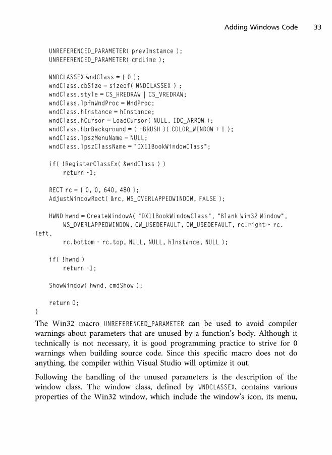
The Win32 macro UNREFERENCED_PARAMETER can be used to avoid compilerwarnings about parameters that are unused by a function’s body. Although ittechnically is not necessary, it is good programming practice to strive for 0warnings when building source code. Since this specific macro does not doanything, the compiler within Visual Studio will optimize it out.
Following the handling of the unused parameters is the description of thewindow class. The window class, defined by WNDCLASSEX, contains variousproperties of the Win32 window, which include the window’s icon, its menu,
Adding Windows Code 33
the application instance the window belongs to, the look of the cursor, and otherproperties we’ll briefly review. The WNDCLASSEX can be found in Winuser.h,which is included within windows.h and has the following definition:
typedef struct tagWNDCLASSEX {UINT cbSize;UINT style;WNDPROC lpfnWndProc;int cbClsExtra;int cbWndExtra;HINSTANCE hInstance;HICON hIcon;HCURSOR hCursor;HBRUSH hbrBackground;LPCTSTR lpszMenuName;LPCTSTR lpszClassName;HICON hIconSm;
} WNDCLASSEX, *PWNDCLASSEX;
The members of the WNDCLASSEX structure are defined as:
n cbSize. The size of the structure in bytes.
n style. Style flags used to define the window’s look.
n lpfnWndProc. A callback function that is called whenever an event notifi-cation comes from the operating system. There will be a function in ourdemos called WndProc that will be discussed later in this chapter, which iswhy we are setting this property. This property is a function pointer.
n cbClsExtra. Number of extra bytes to allocate for the window structure.
n cbWndExtra. Number of extra bytes to allocate for the window’s instance.
n hInstance. The application instance that contains the windows proce-dure (callback) for this window class.
n hIcon. The resource ID for the icon graphic to be displayed for theapplication. If NULL, the default icon is used (e.g., Microsoft Word has anicon of a W on top of a document graphic).
n hCursor. The resource ID for the graphic that will act as the cursor.We’ll usually stick with the standard arrow cursor throughout this book.
34 Chapter 2 n Your First DirectX Program

n hbrBackground. A handle to the background brush that will be used forpainting the window’s background.
n lpszMenuName. A null-terminated string of the resource name for themenu.
n lpszClassName. A null-terminated string for what you wish to nameyour window class. The maximum length is 256 characters.
n hIconSm. Handle to the window’s small icon (i.e., like those seen on run-ning applications on the task bar).
Most members of the window structure deal with Win32 programming that isbeyond the scope of this book, such as creating menus (outside of an editor, we’llmost likely not want to create a Win32 menu in a game). Many of thesemembers we’ll set to a value of 0.
With the WNDCLASSEX structure created we can send it to RegisterClassEx() toregister the window class. The RegisterClassEx() must be called before weattempt to create the window, and it takes as a parameter the address of thewindow class structure to register. If a value of 0 is returned by this function,then the registration failed, and you’ll likely need to check the values specifiedfor the window class to ensure they are all valid, assuming there is not a biggerproblem.
The next step is to create the actual window. First we call AdjustWindowRect tocalculate the size required of the window based on our desired dimensions andstyle. The type of window will determine how much true size we’ll need. If youlook at most Win32 applications, there is space for non-client areas such as thetitle bar, a border around the application, etc. If we are going for a specificwindow size, we’ll have to keep in mind that we have both a client area and anon-client area.
The AdjustWindowRect function first takes a rectangle (lpRect) that defines thebottom left, bottom right, upper left, and upper right areas of the window. Theleft and top properties represent the starting location of the window, while theright and bottom represent the width and height. The AdjustWindowRect
function also takes as parameters the window style flag of the window beingcreated and a Boolean flag indicating whether or not the window has a menu,which affects the non-client area.
Adding Windows Code 35
The window is created next by calling the Win32 function CreateWindow. InListing 2.2 we call a variation of it called CreateWindowA. The main difference isthat CreateWindowA accepts ANSI string parameters, while CreateWindow acceptsUnicode. If using the Unicode version, we can always prefix the letter L beforethe quotes of the string to indicate we are providing Unicode characters.
The Win32 function CreateWindow(A) takes as parameters:
n lpClassName (optional)—The window class name (same name used forthe window class structure).
n lpWindowName (optional)—The window title bar text.
n dwStyle—The window’s style flags.
n X—The window’s horizontal position.
n Y—The window’s vertical position.
n nWidth—The window’s width.
n hHeight—The window’s height.
n hWndParent (optional)—Handle to the parent window’s handle (optionalif this new window is a pop-up or child window).
n hMenu (optional)—Resource handle to the window’s menu.
n hInstance (optional)—The application instance ID (first parameter ofwWinMain).
n lpParam (optional)—Data to be passed to the window and made availablevia the lpParam parameter of the windows proc callback function(discussed in the section titled “Windows Callback Procedures”).
The return value of the CreateWindow(A) function is a non-null handle. IfCreateWindow(A) succeeds, we can show the window by calling the Win32function ShowWindow, which takes as parameters the window handle returned byCreateWindow(A) and the command show flag (cmdShow, which is the wWinMain’slast parameter).
With the window created, the application can begin doing its job. Win32 GUIapplications are event-based applications. This essentially means that when anevent happens, the application is notified of it, and some action then occurs.
36 Chapter 2 n Your First DirectX Program

This continues until the event for quitting the application is encountered. Forexample, when Microsoft Word launches, a “create” event is fired and theapplication loads. Whenever the user clicks the mouse on a toolbar button,menu item, etc., an event is triggered and sent to the application for processing.If the mouse-click event over the open file button is triggered, then a dialog boxis displayed that allows users to visually select the file they wish to open. Manyapplications work using an event-based approach.
In video games, the applications are real time, meaning that whether or notsome event or action takes place will not keep the application from performingmany tasks throughout its lifetime. If the user presses buttons on the game-padcontroller, usually it is detected during an update step of the game loop, and thegame responds to it appropriately. If there are no events, the game still mustprocess constantly by rendering the current game state (e.g., rendering themenu, cinematic, game world, etc.), performing logic updates, looking for andresponding to networking data, playing audio, and so much more.
Either way, both real-time and event-based programs must run until the userdecides to quit. This introduces the concept of the application loop. Theapplication loop is literally an infinite loop that continues until it is somehowbroken by a user’s action. This can be done by receiving a WM_QUIT (Win32 quitmessage) event, the user pressing the Escape key at a point in the main menuwhere it makes sense to close the application (e.g., hitting Escape while the gameis being played might bring up a pause screen but shouldn’t just quit theapplication, unless you design it that way), or any number of other ways youdesign it to quit. Later on in this book, the demos will quit only when the userpresses the Escape key, clicks the close “X” button on the window, or press theBack button on an Xbox 360 game-pad controller.
Listing 2.3 shows an example of the application loop we’ll use throughout thisbook, minus anything related to Direct3D or the demos themselves. The com-ments within Listing 2.3 are placeholders for where we’ll place function calls forour demo and Direct3D-related code later on. If we’ve implemented a statemanagement system, which is useful for game menus, in-game interfaces, andmore, we could have the demo’s one-time initialize and shutdown in the loopitself. Since the state management would never allow the initialization andshutdown states to occur more than once per run, this would work fine. There
Adding Windows Code 37

are a number of game menu tutorials at www.UltimateGameProgramming.comfor those of you interested in more advanced topics beyond the scope of this book.
Listing 2.3 The application loop.
int WINAPI wWinMain( HINSTANCE hInstance, HINSTANCE prevInstance,LPWSTR cmdLine, int cmdShow )
{UNREFERENCED_PARAMETER( prevInstance );UNREFERENCED_PARAMETER( cmdLine );
. . .
// Demo Initialize
MSG msg = { 0 };
while( msg.message != WM_QUIT ){
if( PeekMessage( &msg, 0, 0, 0, PM_REMOVE ) ){
TranslateMessage( &msg );DispatchMessage( &msg );
}else{
// Update// Draw
}}
// Demo Shutdown
return static_cast<int>( msg.wParam );}
As a quick reference, the static_cast<> operator is a C++ operator used toperform casts. The old C-style casts, for example int a = ( int )floatVar, arenot recommended in C++ even though it is legal to do. It is good programmingpractice to use C++ casting keywords over C-style casts. The static_cast<>
38 Chapter 2 n Your First DirectX Program

operator is best used when casting numerical data, like we are doing in Listing2.3 by casting the wParam to an integer. But beware when trying to cast pointersof base classes to derived class and vice-versa, as these are not always going tobe safe. In such a case it would be better to use dynamic_cast<>. Also,static_cast<> does not do run-time checking like dynamic_cast<>. Thedynamic_cast<> is safer but only works on pointers. Although C-style castsare legal, here are some general thoughts to keep in mind:
n C++ style casts are clear in their intent (dynamic_casts for pointers,const_cast for handling const-ness, etc).
n If you try to perform illegal casts with C++ style casts, the compiler willgive an error.
n It’s easier to spot casts within code when using C++ style casts versus C-style (although the syntax highlighting in Visual Studio can sometimeshelp when spotting them).
n C-style casts on objects with multiple inheritance or casting objectaddresses to char* and using pointer arithmetic on them can cause unde-fined behavior.
n C-style casts are easy to misuse.
In Listing 2.3, MSG is a Win32 structure used to hold window messages, some ofwhich come from the operating system, and it is up to the application to respondto these messages. If this does not happen after a certain amount of time haspassed, the operating system will report the application as not responding.Usually we assume this means the application has frozen or has had some erroroccur, but generally it means the application has not talked back to the operatingsystem in a while. If the application is designed to respond to the OS, after awhile it can be safe to assume the program froze whenever Windows displays the“Not Responding” message next to the window’s title on the title bar or next tothe application’s name on the Task Manager. There have been times when I’verun really complex and long queries over a network in Microsoft Access and hadthe operating system report the program as not responding, although it was justbusy doing some task and not processing events.
Adding Windows Code 39
With window messages we need to do two things. First we need to get newmessages and process them, and second we need to dispatch (respond) to thesemessages. The PeekMessage Win32 function retrieves a message for the asso-ciated window (the window we’ve created using CreateWindow). The firstparameter is the structure that will hold the message (its address), the windowhandle (optional), min and max message filter flags (optional), and the removeflag. Specifying PM_REMOVE as the remove flag like we’ve done removes it from thequeue. Since we are processing this message, it will not need to stay on the queueonce we’ve handled it.
If there is a message obtained by PeekMessage, we can respond to that messageby calling TranslateMessage and DispatchMessage. The Win32 functionTranslateMessage translates the messages from virtual-key messages to char-acter messages, and the DispatchMessage function dispatches the message tothe Windows procedure callback function, which will be covered in the nextsection. The Windows procedure function will actually perform actions basedon the message it receives.
If there are no messages, the only thing to do is to perform game updates andrendering. In the demos throughout this book this boils down to performing anydemo-specific updates, which can be detecting and responding to user input,physics calculations, animations, updating audio buffers, etc., and to render thescene geometry.
This is a simplified look at the game loop, which is a series of game-specific stepstaken for each rendered frame. One frame in a game is a single iteration of thegame loop. Most games strive to reach 30 or 60 frames per second, or in otherwords 30 to 60 game loop iterations for each second of real-world time. Asgames become more complex, this is harder to achieve. The frames per second ofa game is usually viewed as how fast the game can render, but games are morethan just rendering code, and often the game’s physics, collisions, artificialintelligence, audio, streaming, and so forth affect the game’s overall frames persecond.
Within the application loop we can perform one iteration of the game loop. InListing 2.3 we have comment placeholders for where we will add the update andrender functions in a later demo. Since we are not at the Direct3D section yet,this will come later.
40 Chapter 2 n Your First DirectX Program

The last line of code in the wWinMain function of the Blank Win32 Windowdemo returns 0. Generally you are returning an exit code, which would onlymatter if you launched one application from another application, and the resultsof that application’s exit status mattered. Later on, once we add Direct3D, we’llreturn the exit code message, although for our purposes the value we returndoesn’t matter as much. Even in C++ console applications it is common forcoders to just return 0 all the time.
The entire Blank Win32 Window wWinMain function with all the informationwe’ve discussed can be seen in Listing 2.4.
Listing 2.4 The Blank Win32 Window demo’s wWinMain in its entirety.
#include<Windows.h>
LRESULT CALLBACK WndProc( HWND hwnd, UINT message,WPARAM wParam, LPARAM lParam );
int WINAPI wWinMain( HINSTANCE hInstance, HINSTANCE prevInstance,LPWSTR cmdLine, int cmdShow )
{UNREFERENCED_PARAMETER( prevInstance );UNREFERENCED_PARAMETER( cmdLine );
WNDCLASSEX wndClass = { 0 };wndClass.cbSize = sizeof( WNDCLASSEX ) ;wndClass.style = CS_HREDRAW | CS_VREDRAW;wndClass.lpfnWndProc = WndProc;wndClass.hInstance = hInstance;wndClass.hCursor = LoadCursor( NULL, IDC_ARROW );wndClass.hbrBackground = ( HBRUSH )( COLOR_WINDOW + 1 );wndClass.lpszMenuName = NULL;wndClass.lpszClassName = "DX11BookWindowClass";
if( !RegisterClassEx( &wndClass ) )return -1;
RECT rc = { 0, 0, 640, 480 };AdjustWindowRect( &rc, WS_OVERLAPPEDWINDOW, FALSE );
Adding Windows Code 41
HWND hwnd = CreateWindowA( "DX11BookWindowClass", "Blank Win32 Window",WS_OVERLAPPEDWINDOW, CW_USEDEFAULT, CW_USEDEFAULT, rc.right - rc.
left,rc.bottom - rc.top, NULL, NULL, hInstance, NULL );
if( !hwnd )return -1;
ShowWindow( hwnd, cmdShow );
// Demo Initialize
MSG msg = { 0 };
while( msg.message != WM_QUIT ){
if( PeekMessage( &msg, 0, 0, 0, PM_REMOVE ) ){
TranslateMessage( &msg );DispatchMessage( &msg );
}// Update// Draw
}
// Demo Shutdown
return static_cast<int>( msg.wParam );}
Windows Callback Procedure
The last piece of the puzzle before we can compile and build our application is toprovide the windows procedure, often called windows proc function. Through-out the previous code listing (Listing 2.4) there was a forward declaration for thisfunction, and in the wWinMain function it was passed to the WNDCLASSEX structureto one of its function, pointer members. The windows proc function is a callbackfunction, meaning that it is called whenever messages are being obtained andprocessed by our application. The Blank Win32 Window demo’s window proc
function can be seen in Listing 2.5.
42 Chapter 2 n Your First DirectX Program
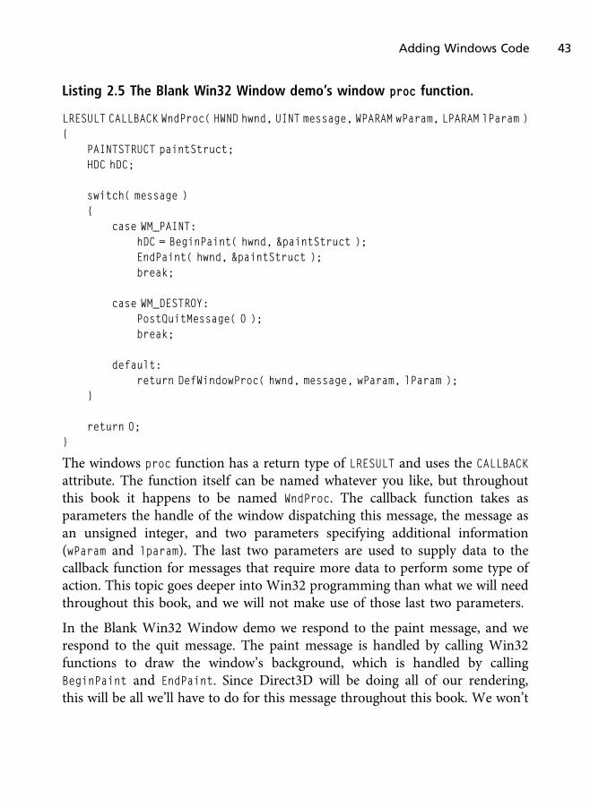
Listing 2.5 The Blank Win32 Window demo’s window proc function.
LRESULT CALLBACK WndProc( HWND hwnd, UINT message, WPARAM wParam, LPARAM lParam ){
PAINTSTRUCT paintStruct;HDC hDC;
switch( message ){
case WM_PAINT:hDC = BeginPaint( hwnd, &paintStruct );EndPaint( hwnd, &paintStruct );break;
case WM_DESTROY:PostQuitMessage( 0 );break;
default:return DefWindowProc( hwnd, message, wParam, lParam );
}
return 0;}
The windows proc function has a return type of LRESULT and uses the CALLBACK
attribute. The function itself can be named whatever you like, but throughoutthis book it happens to be named WndProc. The callback function takes asparameters the handle of the window dispatching this message, the message asan unsigned integer, and two parameters specifying additional information(wParam and lparam). The last two parameters are used to supply data to thecallback function for messages that require more data to perform some type ofaction. This topic goes deeper into Win32 programming than what we will needthroughout this book, and we will not make use of those last two parameters.
In the Blank Win32 Window demo we respond to the paint message, and werespond to the quit message. The paint message is handled by calling Win32functions to draw the window’s background, which is handled by callingBeginPaint and EndPaint. Since Direct3D will be doing all of our rendering,this will be all we’ll have to do for this message throughout this book. We won’t
Adding Windows Code 43

have Direct3D-specific code with this message. but it is still a required messageto respond to.
The quit message is handled by calling the Win32 PostQuitMessage function,which will cause the MSG object in our application loop to retrieve a WM_QUIT
message, which causes the application loop to end and the application to quit aswe’ve intended. Since there are situations where we don’t want to just flat-outquit, we can use this to only post a quit message if we really want to quit. Forexample, in Microsoft Word if you try to quit without saving, a dialog pop-upappears asking you if you wish to save before exiting, exit without saving, orcancel exiting altogether.
The final part of the windows proc function is the calling of DefWindowProc,which takes the same parameters as the windows proc function. This function isonly called on messages for which we are not writing custom response code. Inthis demo we are responding to paint requests from the operating system andquit messages but there is a ton of other events we could also look for, such askey presses, mouse clicks, mouse movements, timers, and much more. TheDefWindowProc function is a Win32 function that processes every message sent toit with default processing behavior and is used to ensure that we at least respondto every message, even if we don’t actually care about them.
At this point you can compile and build the demo. There should be 0 warningsand 0 errors and, if so, you can run the application to be greeted to an emptywhite window. To close this application you can click on the close “X” button onthe upper right corner of the window, which will cause the quit message to beprocessed, the application loop to break, and the program to exit successfully. Ascreenshot from the Blank Win32 Window demo can be seen in Figure 2.5.
The Blank Win32 Window demo code and project can be found on the book’scompanion website in the Chapter 2/BlankWindow folder.
Time for Direct3D
We are now ready to add Direct3D 11 to the code we’ve written in the BlankWin32 Window demo to create a new demo called Blank Direct3D Window.
The Blank Direct3D Window demo can be found on the companion website inthe Chapter2/BlankD3DWindow folder.
44 Chapter 2 n Your First DirectX Program

In this section we’ll first discuss all of the Direct3D functions and objectsnecessary to get started with Direct3D 11. In the next section we’ll cover theBlank Direct3D Window demo in detail. Discussing everything needed to startDirect3D first outside of the specific chapter demo will make implementing theBlank Direct3D Window demo as a chapter tutorial much easier for beginners.
If you wish to follow along with the creation of the Blank Direct3D Windowdemo, create a new project titled BlankD3DWindow and copy the main.cppsource file from the Blank Win32 Window demo over to this one. This newdemo will build off of that code.
Adding the DirectX Libraries
Before we begin we must include the DirectX 11 libraries that we’ll be using. Tolink the DirectX libraries, click on the Project menu item and select [projectname] Properties from the drop-down list, where [project name] is, in this case,
Figure 2.5
The Blank Win32 Window demo running.
Time for Direct3D 45
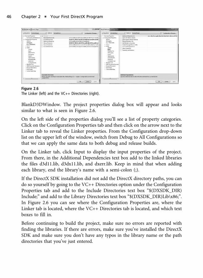
BlankD3DWindow. The project properties dialog box will appear and lookssimilar to what is seen in Figure 2.6.
On the left side of the properties dialog you’ll see a list of property categories.Click on the Configuration Properties tab and then click on the arrow next to theLinker tab to reveal the Linker properties. From the Configuration drop-downlist on the upper left of the window, switch from Debug to All Configurations sothat we can apply the same data to both debug and release builds.
On the Linker tab, click Input to display the input properties of the project.From there, in the Additional Dependencies text box add to the linked librariesthe files d3d11.lib, d3dx11.lib, and dxerr.lib. Keep in mind that when addingeach library, end the library’s name with a semi-colon (;).
If the DirectX SDK installation did not add the DirectX directory paths, you cando so yourself by going to the VC++ Directories option under the ConfigurationProperties tab and add to the Include Directories text box “$(DXSDK_DIR)Include;” and add to the Library Directories text box “$(DXSDK_DIR)Lib\x86;”.In Figure 2.6 you can see where the Configuration Properties are, where theLinker tab is located, where the VC++ Directories tab is located, and which textboxes to fill in.
Before continuing to build the project, make sure no errors are reported withfinding the libraries. If there are errors, make sure you’ve installed the DirectXSDK and make sure you don’t have any typos in the library name or the pathdirectories that you’ve just entered.
Figure 2.6
The Linker (left) and the VC++ Directories (right).
46 Chapter 2 n Your First DirectX Program

Initializing Direct3D
To set up Direct3D we need to complete the following four steps:
1. Define the device types and feature levels we want to check for.
2. Create the Direct3D device, rendering context, and swap chain.
3. Create the render target.
4. Set the viewport.
In this section we’ll discuss each of these steps one at a time and cover in detailthe various Direct3D objects and functions used.
Driver Types and Features Levels
In Direct3D 11 we can have a hardware device, a WARP device, a softwaredriver device, or a reference device.
A hardware device is a Direct3D device that runs on the graphics hardware andis the fastest of all devices. This is the type of device you should be able to createif you have graphics hardware that supports the feature level we are aiming for,which will be discussed momentarily.
A reference device is used for users without hardware support by performing therendering on the CPU. In other words, the reference device completely emulateshardware rendering on the CPU within software. This process is very slow,inefficient, and should only be used during development if there is no otheralternative. This is useful when new versions of DirectX are released, but there isno hardware on the market that can run it with a hardware device.
A software driver device allows developers to write their own softwarerendering driver and use it with Direct3D. This is called a pluggable softwaredriver. Usually this option is not recommended for high-performance,demanding applications where hardware, or maybe even WARP, would bethe better option.
The WARP device is an efficient CPU-rendering device that emulates the fullfeature set of Direct3D. WARP uses the Windows Graphic runtime found inWindows Vista and Windows 7 and uses highly optimized instructions andcode, which makes it a better choice than reference mode. This device is said to
Time for Direct3D 47
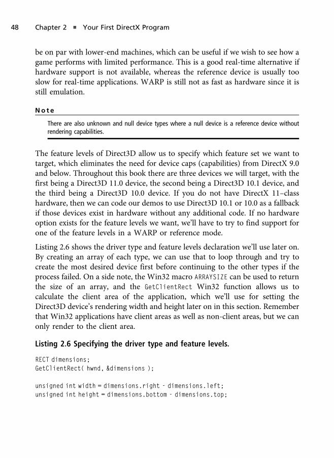
be on par with lower-end machines, which can be useful if we wish to see how agame performs with limited performance. This is a good real-time alternative ifhardware support is not available, whereas the reference device is usually tooslow for real-time applications. WARP is still not as fast as hardware since it isstill emulation.
No t e
There are also unknown and null device types where a null device is a reference device withoutrendering capabilities.
The feature levels of Direct3D allow us to specify which feature set we want totarget, which eliminates the need for device caps (capabilities) from DirectX 9.0and below. Throughout this book there are three devices we will target, with thefirst being a Direct3D 11.0 device, the second being a Direct3D 10.1 device, andthe third being a Direct3D 10.0 device. If you do not have DirectX 11–classhardware, then we can code our demos to use Direct3D 10.1 or 10.0 as a fallbackif those devices exist in hardware without any additional code. If no hardwareoption exists for the feature levels we want, we’ll have to try to find support forone of the feature levels in a WARP or reference mode.
Listing 2.6 shows the driver type and feature levels declaration we’ll use later on.By creating an array of each type, we can use that to loop through and try tocreate the most desired device first before continuing to the other types if theprocess failed. On a side note, the Win32 macro ARRAYSIZE can be used to returnthe size of an array, and the GetClientRect Win32 function allows us tocalculate the client area of the application, which we’ll use for setting theDirect3D device’s rendering width and height later on in this section. Rememberthat Win32 applications have client areas as well as non-client areas, but we canonly render to the client area.
Listing 2.6 Specifying the driver type and feature levels.
RECT dimensions;GetClientRect( hwnd, &dimensions );
unsigned int width = dimensions.right - dimensions.left;unsigned int height = dimensions.bottom - dimensions.top;
48 Chapter 2 n Your First DirectX Program

D3D_DRIVER_TYPE driverTypes[] ={
D3D_DRIVER_TYPE_HARDWARE, D3D_DRIVER_TYPE_WARP, D3D_DRIVER_TYPE_SOFTWARE};
unsigned int totalDriverTypes = ARRAYSIZE( driverTypes );
D3D_FEATURE_LEVEL featureLevels[] ={
D3D_FEATURE_LEVEL_11_0,D3D_FEATURE_LEVEL_10_1,D3D_FEATURE_LEVEL_10_0
};
unsigned int totalFeatureLevels = ARRAYSIZE( featureLevels );
Device and Swap Chain Creation
The next step is the creation of the swap chain. A swap chain in Direct3D is acollection of rendering destinations for a device. Each device has at least oneswap chain, but multiple swap chains can be created for multiple devices. Arendering destination can be a color buffer that is rendered to and displayed tothe screen, a depth buffer (discussed in Chapter 3, “The 2D Resurgence”), astencil buffer (also discussed in Chapter 3), and so forth.
Usually in games we have two color buffers that are being rendered onto calledthe primary buffer and the secondary buffer, as well as being known as the frontand back buffers. The primary buffer (front buffer) is the one that is displayed tothe screen, while the secondary buffer (back buffer) is being drawn to for thenext frame.
Rendering can occur so fast that parts of the screen can be drawn on top of theprevious results before the monitor has finished updating the display. When thishappens it causes rendering artifacts and undesirable issues. Switching betweenthe buffers so that one is being written onto and the other is being displayedallows games to avoid these artifacts. This ping-pong technique is called doublebuffering (also called page flipping) in computer graphics. A swap chain canhave one, two, or more of these buffers, and Direct3D handles the buffer pageflipping between them all.
Time for Direct3D 49

Listing 2.7 shows the creation of a swap chain description. A swap chaindescription is used to define how we want the swap chain created. It has amember for:
n The buffer count (primary/secondary buffer for page flipping).
n The width and height of the buffers.
n The buffer’s format (describe in the section titled “Formats” later in thischapter).
n The refresh rate, which is used to determine how often the display isrefreshed in Hertz (by using 60/1 we are specifying a 60 Hertz refreshrate).
n The window handle (same window created by CreateWindow(A)).
n A Boolean flag called Windowed that is used to specify whether Direct3Dshould stay windowed or resize into full-screen mode.
n The sample count and quality for the sample description.
Listing 2.7 The swap chain description.
DXGI_SWAP_CHAIN_DESC swapChainDesc;ZeroMemory( &swapChainDesc, sizeof( swapChainDesc ) );swapChainDesc.BufferCount = 1;swapChainDesc.BufferDesc.Width = width;swapChainDesc.BufferDesc.Height = height;swapChainDesc.BufferDesc.Format = DXGI_FORMAT_R8G8B8A8_UNORM;swapChainDesc.BufferDesc.RefreshRate.Numerator = 60;swapChainDesc.BufferDesc.RefreshRate.Denominator = 1;swapChainDesc.BufferUsage = DXGI_USAGE_RENDER_TARGET_OUTPUT;swapChainDesc.OutputWindow = hwnd;swapChainDesc.Windowed = true;swapChainDesc.SampleDesc.Count = 1;swapChainDesc.SampleDesc.Quality = 0;
The sample description defines the multisampling properties of Direct3D.Multisampling is a technique used to sample and average rendered pixels tocreate smoother transitions between sharp color changes. The artifacts we areattempting to reduce with multisampling are called jagged edges, also known asthe staircase effect. Figure 2.7 shows an example of this effect on the left, as well
50 Chapter 2 n Your First DirectX Program
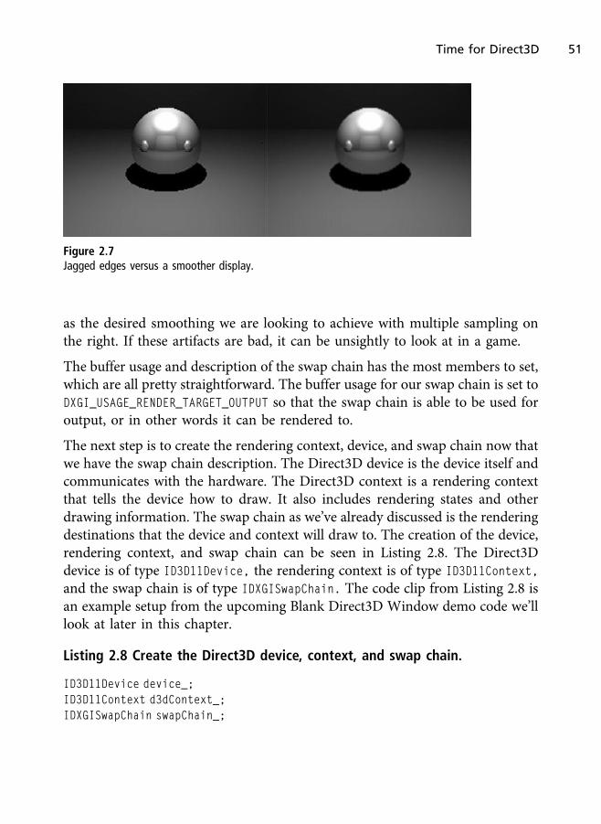
as the desired smoothing we are looking to achieve with multiple sampling onthe right. If these artifacts are bad, it can be unsightly to look at in a game.
The buffer usage and description of the swap chain has the most members to set,which are all pretty straightforward. The buffer usage for our swap chain is set toDXGI_USAGE_RENDER_TARGET_OUTPUT so that the swap chain is able to be used foroutput, or in other words it can be rendered to.
The next step is to create the rendering context, device, and swap chain now thatwe have the swap chain description. The Direct3D device is the device itself andcommunicates with the hardware. The Direct3D context is a rendering contextthat tells the device how to draw. It also includes rendering states and otherdrawing information. The swap chain as we’ve already discussed is the renderingdestinations that the device and context will draw to. The creation of the device,rendering context, and swap chain can be seen in Listing 2.8. The Direct3Ddevice is of type ID3D11Device, the rendering context is of type ID3D11Context,
and the swap chain is of type IDXGISwapChain. The code clip from Listing 2.8 isan example setup from the upcoming Blank Direct3D Window demo code we’lllook at later in this chapter.
Listing 2.8 Create the Direct3D device, context, and swap chain.
ID3D11Device device_;ID3D11Context d3dContext_;IDXGISwapChain swapChain_;
Figure 2.7
Jagged edges versus a smoother display.
Time for Direct3D 51
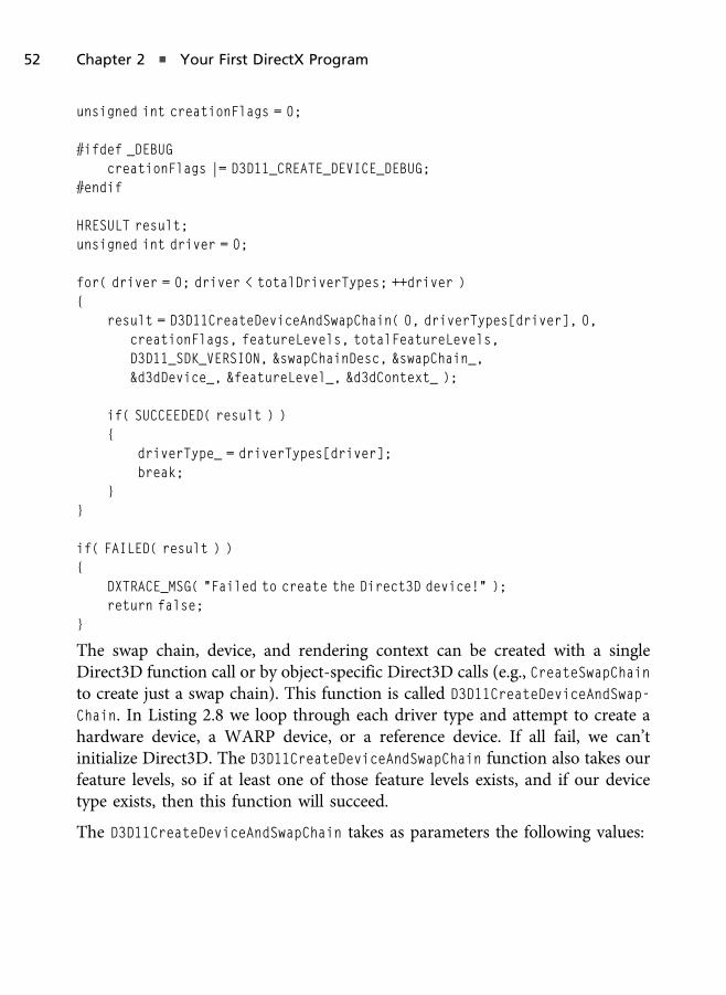
unsigned int creationFlags = 0;
#ifdef _DEBUGcreationFlags |= D3D11_CREATE_DEVICE_DEBUG;
#endif
HRESULT result;unsigned int driver = 0;
for( driver = 0; driver < totalDriverTypes; ++driver ){
result = D3D11CreateDeviceAndSwapChain( 0, driverTypes[driver], 0,creationFlags, featureLevels, totalFeatureLevels,D3D11_SDK_VERSION, &swapChainDesc, &swapChain_,&d3dDevice_, &featureLevel_, &d3dContext_ );
if( SUCCEEDED( result ) ){
driverType_ = driverTypes[driver];break;
}}
if( FAILED( result ) ){
DXTRACE_MSG( "Failed to create the Direct3D device!" );return false;
}
The swap chain, device, and rendering context can be created with a singleDirect3D function call or by object-specific Direct3D calls (e.g., CreateSwapChainto create just a swap chain). This function is called D3D11CreateDeviceAndSwap-
Chain. In Listing 2.8 we loop through each driver type and attempt to create ahardware device, a WARP device, or a reference device. If all fail, we can’tinitialize Direct3D. The D3D11CreateDeviceAndSwapChain function also takes ourfeature levels, so if at least one of those feature levels exists, and if our devicetype exists, then this function will succeed.
The D3D11CreateDeviceAndSwapChain takes as parameters the following values:
52 Chapter 2 n Your First DirectX Program

n A pointer to the video adapter to use to create the device. Passing nullcauses Direct3D to use the default device. This can be useful if there ismore than one device installed in the machine.
n The driver type we wish to create (i.e., hardware, WARP, software, orreference).
n A handle to a DLL that implements a software rendering device. If ourdriver type is software (D3D_DRIVER_TYPE_SOFTWARE), then this parameterCANNOT be null.
n The creation flags. In Direct3D a creation flag of 0 can be used in releasebuilds of our games, while a creation flag of D3D11_CREATE_DEVICE_DEBUGallows us to create a device with debugging capabilities, which is usefulfor development.
n The feature levels we wish to target, ordered from the most desired tothe least desired. In this book we are concerned with Direct3D 11 orDirect3D 10, but we could also target Direct3D 9 through D3D_FEATURE_
LEVEL_9_3, D3D_FEATURE_LEVEL_9_2, or D3D_FEATURE_LEVEL_9_1.
n Number of feature levels in the feature levels array.
n The SDK version, which will always be D3D11_SDK_VERSION since we areusing the DirectX 11 SDK.
n The swap chain description object.
n The address for the device object (with the device being of type ID3D11-
Device).
n The address of the feature level that was selected. Earlier we supplied alist of features we want but only one is chosen, which is stored in thisaddress.
n The address for the rendering context (with the context being of the typeID3D11Context).
Render Target View Creation
A render target view is a Direct3D resource written to by the output mergerstage. In order for the output merger to render to the swap chain’s back buffer(secondary buffer), we create a render target view of it.
Time for Direct3D 53

In Chapter 3 we’ll discuss textures in detail, but for now understand that atexture is often an image. The primary and secondary rendering buffers of theswap chain are color textures, and to obtain a pointer to it we call the swap chainfunction GetBuffer. GetBuffer takes as parameters:
n The buffer index (a value of 0 gives us the first buffer).
n The type of interface we are trying to manipulate. The type of a 2D tex-ture is ID3D11Texture2D.
n The address of the buffer we are obtaining. We must cast to LPVOID.
With a pointer to the buffer, we call CreateRenderTargetView, which is afunction of the Direct3D device object, to create the render target view. Rendertarget views have the type of ID3D11RenderTargetView, and the CreateRender
TargetView function takes as parameters the 2D texture we are creating the viewfor, the render target description, and the address of the ID3D11RenderTarget
View object we are creating. Setting the render target description parameter tonull gives us a view of the entire surface at mip level 0. Mip-map levels will bediscussed in more detail in Chapter 3.
Once we are done creating the render target view, we can release our pointer tothe back buffer of the swap chain. Since we obtained a reference via a COMobject, we must call the COM’s Release function to decrement the referencecount. This must be done to avoid memory leaks, because we don’t want thesystem holding onto it once the application quits.
Each time we want to render to a specific render target, we must set it firstbefore any drawing calls. This is done by calling OMSetRenderTarget, which is afunction that is part of the output merger (hence the OM in OMSetRenderTarget).The OMSetRenderTarget function takes as parameters the number of views we arebinding in this function call, the list of render target views, and the depth/stencilviews. We’ll discuss depth and stencils in Chapter 3. Listing 2.9 shows thecreation and binding of the render target view.
Listing 2.9 The creation and binding of the render target view.
ID3D11RenderTargetView* backBufferTarget_;ID3D11Texture2D* backBufferTexture;
54 Chapter 2 n Your First DirectX Program

HRESULT result = swapChain_->GetBuffer( 0, __uuidof( ID3D11Texture2D ),( LPVOID* )&backBufferTexture );
if( FAILED( result ) ){
DXTRACE_MSG( "Failed to get the swap chain back buffer!" );return false;
}
result = d3dDevice_->CreateRenderTargetView( backBufferTexture, 0,&backBufferTarget_ );
if( backBufferTexture )backBufferTexture->Release( );
if( FAILED( result ) ){
DXTRACE_MSG( "Failed to create the render target view!" );return false;
}
d3dContext_->OMSetRenderTargets( 1, &backBufferTarget_, 0 );
You’ll notice in Listing 2.9 that we are using a macro called DXTRACE_MSG. Thismacro is used for debugging purposes, and we’ll discuss it in more detail at theend of this chapter, along with the other DirectX Error Handling Library.
The Viewport
The last piece of the Direct3D 11 puzzle is the creation and setting of theviewport. The viewport defines the area of the screen we are rendering to. Insingle player or non-split-screen multiplayer games this is often the entirescreen, and so we set the viewport’s width and height to the Direct3D swapchain’s width and height. For split-screen games we can create two viewports,with one defining the upper portion of the screen and one for the lower portion.In order to render split-screen views we would have to render the scene once forplayer 1’s perspective, once for player 2’s perspective, etc. Although multiplayergames are beyond the scope of this book, an example of creating a split-screendemo can be found at www.UltimateGameProgramming.com.
Time for Direct3D 55
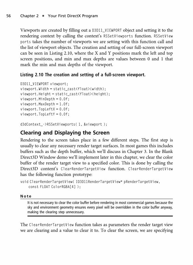
Viewports are created by filling out a D3D11_VIEWPORT object and setting it to therendering context by calling the context’s RSSetViewports function. RSSetViewports takes the number of viewports we are setting with this function call andthe list of viewport objects. The creation and setting of our full-screen viewportcan be seen in Listing 2.10, where the X and Y positions mark the left and topscreen positions, and min and max depths are values between 0 and 1 thatmark the min and max depths of the viewport.
Listing 2.10 The creation and setting of a full-screen viewport.
D3D11_VIEWPORT viewport;viewport.Width = static_cast<float>(width);viewport.Height = static_cast<float>(height);viewport.MinDepth = 0.0f;viewport.MaxDepth = 1.0f;viewport.TopLeftX = 0.0f;viewport.TopLeftY = 0.0f;
d3dContext_->RSSetViewports( 1, &viewport );
Clearing and Displaying the Screen
Rendering to the screen takes place in a few different steps. The first step isusually to clear any necessary render target surfaces. In most games this includesbuffers such as the depth buffer, which we’ll discuss in Chapter 3. In the BlankDirect3D Window demo we’ll implement later in this chapter, we clear the colorbuffer of the render target view to a specified color. This is done by calling theDirect3D content’s ClearRenderTargetView function. ClearRenderTargetView
has the following function prototype:
void ClearRenderTargetView( ID3D11RenderTargetView* pRenderTargetView,const FLOAT ColorRGBA[4] );
No t e
It is not necessary to clear the color buffer before rendering in most commercial games because thesky and environment geometry ensures every pixel will be overridden in the color buffer anyway,making the clearing step unnecessary.
The ClearRenderTargetView function takes as parameters the render target viewwe are clearing and a value to clear it to. To clear the screen, we are specifying
56 Chapter 2 n Your First DirectX Program
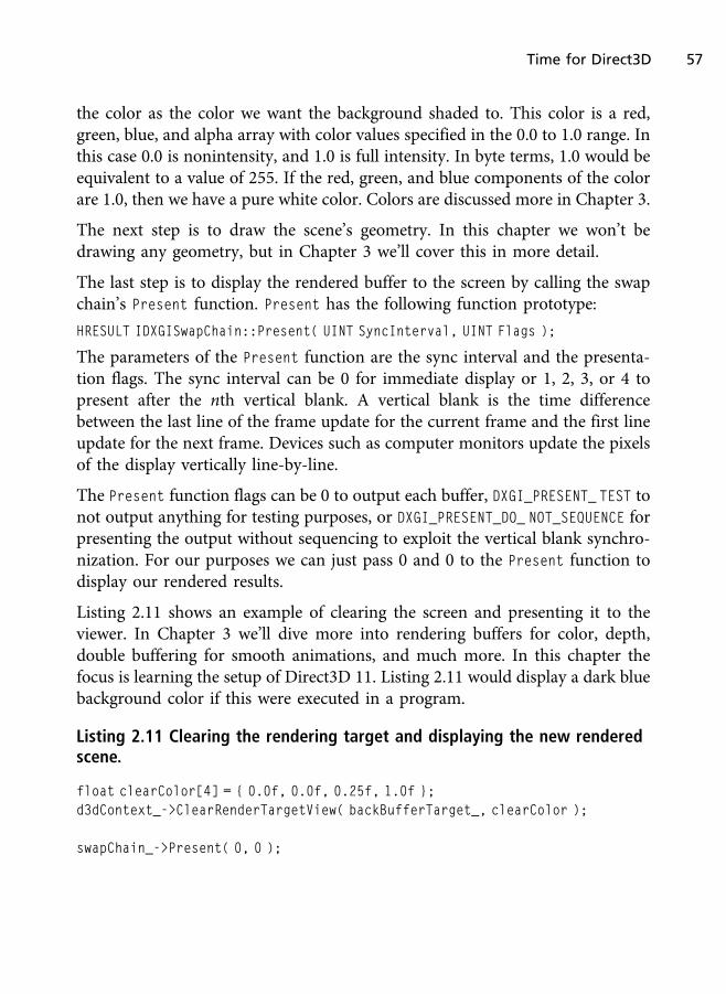
the color as the color we want the background shaded to. This color is a red,green, blue, and alpha array with color values specified in the 0.0 to 1.0 range. Inthis case 0.0 is nonintensity, and 1.0 is full intensity. In byte terms, 1.0 would beequivalent to a value of 255. If the red, green, and blue components of the colorare 1.0, then we have a pure white color. Colors are discussed more in Chapter 3.
The next step is to draw the scene’s geometry. In this chapter we won’t bedrawing any geometry, but in Chapter 3 we’ll cover this in more detail.
The last step is to display the rendered buffer to the screen by calling the swapchain’s Present function. Present has the following function prototype:
HRESULT IDXGISwapChain::Present( UINT SyncInterval, UINT Flags );
The parameters of the Present function are the sync interval and the presenta-tion flags. The sync interval can be 0 for immediate display or 1, 2, 3, or 4 topresent after the nth vertical blank. A vertical blank is the time differencebetween the last line of the frame update for the current frame and the first lineupdate for the next frame. Devices such as computer monitors update the pixelsof the display vertically line-by-line.
The Present function flags can be 0 to output each buffer, DXGI_PRESENT_ TEST tonot output anything for testing purposes, or DXGI_PRESENT_DO_ NOT_SEQUENCE forpresenting the output without sequencing to exploit the vertical blank synchro-nization. For our purposes we can just pass 0 and 0 to the Present function todisplay our rendered results.
Listing 2.11 shows an example of clearing the screen and presenting it to theviewer. In Chapter 3 we’ll dive more into rendering buffers for color, depth,double buffering for smooth animations, and much more. In this chapter thefocus is learning the setup of Direct3D 11. Listing 2.11 would display a dark bluebackground color if this were executed in a program.
Listing 2.11 Clearing the rendering target and displaying the new renderedscene.
float clearColor[4] = { 0.0f, 0.0f, 0.25f, 1.0f };d3dContext_->ClearRenderTargetView( backBufferTarget_, clearColor );
swapChain_->Present( 0, 0 );
Time for Direct3D 57
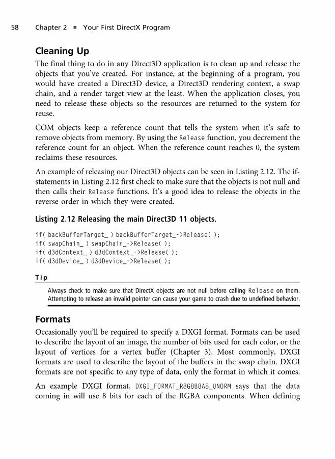
Cleaning Up
The final thing to do in any Direct3D application is to clean up and release theobjects that you’ve created. For instance, at the beginning of a program, youwould have created a Direct3D device, a Direct3D rendering context, a swapchain, and a render target view at the least. When the application closes, youneed to release these objects so the resources are returned to the system forreuse.
COM objects keep a reference count that tells the system when it’s safe toremove objects from memory. By using the Release function, you decrement thereference count for an object. When the reference count reaches 0, the systemreclaims these resources.
An example of releasing our Direct3D objects can be seen in Listing 2.12. The if-statements in Listing 2.12 first check to make sure that the objects is not null andthen calls their Release functions. It’s a good idea to release the objects in thereverse order in which they were created.
Listing 2.12 Releasing the main Direct3D 11 objects.
if( backBufferTarget_ ) backBufferTarget_->Release( );if( swapChain_ ) swapChain_->Release( );if( d3dContext_ ) d3dContext_->Release( );if( d3dDevice_ ) d3dDevice_->Release( );
T i p
Always check to make sure that DirectX objects are not null before calling Release on them.Attempting to release an invalid pointer can cause your game to crash due to undefined behavior.
Formats
Occasionally you’ll be required to specify a DXGI format. Formats can be usedto describe the layout of an image, the number of bits used for each color, or thelayout of vertices for a vertex buffer (Chapter 3). Most commonly, DXGIformats are used to describe the layout of the buffers in the swap chain. DXGIformats are not specific to any type of data, only the format in which it comes.
An example DXGI format, DXGI_FORMAT_R8G8B8A8_UNORM says that the datacoming in will use 8 bits for each of the RGBA components. When defining
58 Chapter 2 n Your First DirectX Program
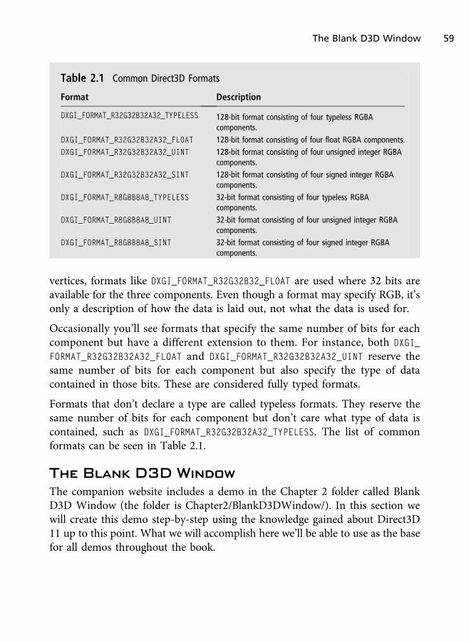
vertices, formats like DXGI_FORMAT_R32G32B32_FLOAT are used where 32 bits areavailable for the three components. Even though a format may specify RGB, it’sonly a description of how the data is laid out, not what the data is used for.
Occasionally you’ll see formats that specify the same number of bits for eachcomponent but have a different extension to them. For instance, both DXGI_
FORMAT_R32G32B32A32_FLOAT and DXGI_FORMAT_R32G32B32A32_UINT reserve thesame number of bits for each component but also specify the type of datacontained in those bits. These are considered fully typed formats.
Formats that don’t declare a type are called typeless formats. They reserve thesame number of bits for each component but don’t care what type of data iscontained, such as DXGI_FORMAT_R32G32B32A32_TYPELESS. The list of commonformats can be seen in Table 2.1.
The Blank D3D Window
The companion website includes a demo in the Chapter 2 folder called BlankD3D Window (the folder is Chapter2/BlankD3DWindow/). In this section wewill create this demo step-by-step using the knowledge gained about Direct3D11 up to this point. What we will accomplish here we’ll be able to use as the basefor all demos throughout the book.
Table 2.1 Common Direct3D Formats
Format Description
DXGI_FORMAT_R32G32B32A32_TYPELESS 128-bit format consisting of four typeless RGBAcomponents.
DXGI_FORMAT_R32G32B32A32_FLOAT 128-bit format consisting of four float RGBA components.
DXGI_FORMAT_R32G32B32A32_UINT 128-bit format consisting of four unsigned integer RGBAcomponents.
DXGI_FORMAT_R32G32B32A32_SINT 128-bit format consisting of four signed integer RGBAcomponents.
DXGI_FORMAT_R8G8B8A8_TYPELESS 32-bit format consisting of four typeless RGBAcomponents.
DXGI_FORMAT_R8G8B8A8_UINT 32-bit format consisting of four unsigned integer RGBAcomponents.
DXGI_FORMAT_R8G8B8A8_SINT 32-bit format consisting of four signed integer RGBAcomponents.
The Blank D3D Window 59

Design of the Template Framework
The setup, shutdown, and initialization of non-demo–specific Direct3D objectsare fairly straightforward, and rewriting essentially the same thing each time wewant to write a new demo can prove unnecessary. Sometimes we want to getstraight to the demo itself without having to write the standard Win32 andDirect3D startup code. Although it is not a big deal, it is at times aninconvenience without resorting to copy-and-paste methods.
To resolve this we will write all the Direct3D startup and cleanup code in onesource file and reuse that code throughout the book. To facilitate this we will createa class called DX11DemoBase. To create our specific demos, we’ll derive from thisbase class and override virtual functions necessary for us to create our demos.
In this section we’ll cover the Blank Direct3D Window demo in its entirety anduse the code created here as the basis for all demos to follow.
The Direct3D Class
But why use a class? Why not use global variables and functions to act on themlike many other books, tutorials, and resources? There are many answers to this,and most of them stem from good versus bad programming practices.
Global variables are looked down upon in programming for many reasons. Ingeneral it is just bad programming to use them, and they should be avoided.Alternatively, we could also pass objects as parameters, but there are too manyobjects that would need to be passed to nearly every function in our application.Of course we could create a class or structure to store them and pass that objectaround, but in the end it makes sense to have a demo class that demo-specificclasses derive from; it makes little sense to return to the C way of doing things.
In our setup, a demo is its own object. It can load the content it needs, renderwhat needs to be rendered, and update what needs to be updated. It has a solitarypurpose and exists to perform a single job. The question now is what will weneed from our base class? For starters, we’ll need functions to do the following:
n Initialize Direct3D
n Release Direct3D objects created during startup
n Store member variables for our Direct3D objects that are not demo-specific
60 Chapter 2 n Your First DirectX Program
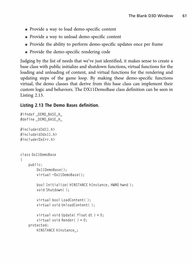
n Provide a way to load demo-specific content
n Provide a way to unload demo-specific content
n Provide the ability to perform demo-specific updates once per frame
n Provide the demo-specific rendering code
Judging by the list of needs that we’ve just identified, it makes sense to create abase class with public initialize and shutdown functions, virtual functions for theloading and unloading of content, and virtual functions for the rendering andupdating steps of the game loop. By making these demo-specific functionsvirtual, the demo classes that derive from this base class can implement theircustom logic and behaviors. The DX11DemoBase class definition can be seen inListing 2.13.
Listing 2.13 The Demo Bases definition.
#ifndef _DEMO_BASE_H_#define _DEMO_BASE_H_
#include<d3d11.h>#include<d3dx11.h>#include<DxErr.h>
class Dx11DemoBase{
public:Dx11DemoBase();virtual ~Dx11DemoBase();
bool Initialize( HINSTANCE hInstance, HWND hwnd );void Shutdown( );
virtual bool LoadContent( );virtual void UnloadContent( );
virtual void Update( float dt ) = 0;virtual void Render( ) = 0;
protected:HINSTANCE hInstance_;
The Blank D3D Window 61

HWND hwnd_;
D3D_DRIVER_TYPE driverType_;D3D_FEATURE_LEVEL featureLevel_;
ID3D11Device* d3dDevice_;ID3D11DeviceContext* d3dContext_;IDXGISwapChain* swapChain_;ID3D11RenderTargetView* backBufferTarget_;
};
#endif
In Listing 2.13 we can see that all of the minimum Direct3D objects we’ll needare included as protected class members. If a demo needs objects specific to thatdemo, such as additional rendering targets, then it is up to that demo-specificclass to declare those as members of the derived class. The base class is just forobjects that are common across all demos.
Taking a look at the member functions of the demo base class, we see that weneed only a few methods to give us the ability to create a wide range of demos.The job of the constructor is to set the member objects to default values like null.To do this we’ll use the constructor’s member initialize list, which is a method ofinitializing member variables outside the body of the constructor. Doing this isoften good programming practice and can be more efficient than letting adefault constructor call occur before a copy constructor on objects. In the case ofour Direct3D objects, they have no constructors, so this is done largely forconsistency. But in general when working with initializing objects, it is a goodidea to avoid unnecessary constructor calls. Although built-in types can beinitialized during the member initialize list or through assignment within theconstructor, the result will be the same either way, since they are built-in typesand not objects.
The class’s destructor is tasked with calling the Shutdown function to ensure thatall Direct3D objects are properly released when the demo is either deleted orfalls out of scope.
The Shutdown function calls Release on all of our COM-based Direct3D objects.In the Shutdown function it is important to release our demo-specific content;
62 Chapter 2 n Your First DirectX Program
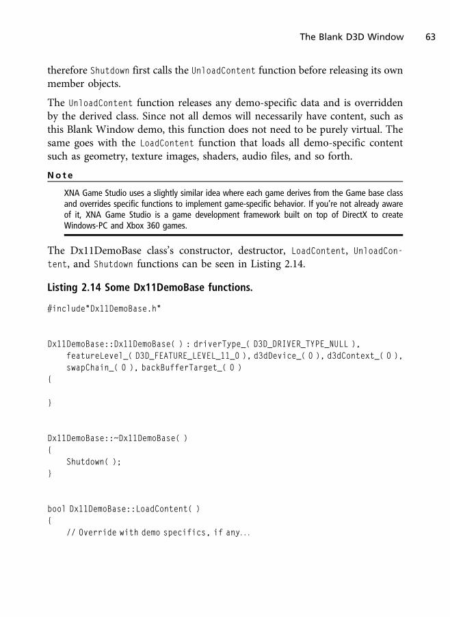
therefore Shutdown first calls the UnloadContent function before releasing its ownmember objects.
The UnloadContent function releases any demo-specific data and is overriddenby the derived class. Since not all demos will necessarily have content, such asthis Blank Window demo, this function does not need to be purely virtual. Thesame goes with the LoadContent function that loads all demo-specific contentsuch as geometry, texture images, shaders, audio files, and so forth.
No t e
XNA Game Studio uses a slightly similar idea where each game derives from the Game base classand overrides specific functions to implement game-specific behavior. If you’re not already awareof it, XNA Game Studio is a game development framework built on top of DirectX to createWindows-PC and Xbox 360 games.
The Dx11DemoBase class’s constructor, destructor, LoadContent, UnloadCon-
tent, and Shutdown functions can be seen in Listing 2.14.
Listing 2.14 Some Dx11DemoBase functions.
#include"Dx11DemoBase.h"
Dx11DemoBase::Dx11DemoBase( ) : driverType_( D3D_DRIVER_TYPE_NULL ),featureLevel_( D3D_FEATURE_LEVEL_11_0 ), d3dDevice_( 0 ), d3dContext_( 0 ),swapChain_( 0 ), backBufferTarget_( 0 )
{
}
Dx11DemoBase::~Dx11DemoBase( ){
Shutdown( );}
bool Dx11DemoBase::LoadContent( ){
// Override with demo specifics, if any. . .
The Blank D3D Window 63

return true;}
void Dx11DemoBase::UnloadContent( ){
// Override with demo specifics, if any. . .}
void Dx11DemoBase::Shutdown( ){
UnloadContent( );
if( backBufferTarget_ ) backBufferTarget_->Release( );if( swapChain_ ) swapChain_->Release( );if( d3dContext_ ) d3dContext_->Release( );if( d3dDevice_ ) d3dDevice_->Release( );d3dDevice_ = 0;d3dContext_ = 0;swapChain_ = 0;backBufferTarget_ = 0;
}
The last function in the Dx11DemoBase class is the Initialize function. TheInitialize function performs the Direct3D initialization as we’ve describedthroughout this chapter. The function begins by declaring our driver types forhardware, WARP, or software, and our feature levels for Direct3D 11.0, 10.1, or10.0. The setup of this code is to attempt to create a hardware device in Direct3D11. If that fails, we’ll try other driver types and feature levels until we find one thatis supported. This also means that if you’re using Direct3D 10 hardware you canstill run this demo in hardware, since the 10.1 or 10.0 feature level will be chosen.
The next step is to create the swap chain description and use that information toattempt to find a supported device type and feature level. If that passes, we createthe render target view out of the swap chain’s back buffer, create the viewport,and call LoadContent to load any demo-specific game content. Since our Direct3Dinitialization must occur before demo-specific initialization, LoadContent must becalled last. By including it here we don’t have to call it manually outside of the
64 Chapter 2 n Your First DirectX Program

class. The same can be said for having to manually call UnloadContent before theapplication quits since Shutdown calls UnloadContent itself.
The full Direct3D 11 initialization can be seen in Listing 2.15 for the BlankDirect3D Window demo. Most of the code deals with error checking and settingproperty values.
Listing 2.15 The Dx11DemoBase Initialize function.
bool Dx11DemoBase::Initialize( HINSTANCE hInstance, HWND hwnd ){
hInstance_ = hInstance;hwnd_ = hwnd;
RECT dimensions;GetClientRect( hwnd, &dimensions );
unsigned int width = dimensions.right - dimensions.left;unsigned int height = dimensions.bottom - dimensions.top;
D3D_DRIVER_TYPE driverTypes[] ={
D3D_DRIVER_TYPE_HARDWARE, D3D_DRIVER_TYPE_WARP, D3D_DRIVER_TYPE_-SOFTWARE
};
unsigned int totalDriverTypes = ARRAYSIZE( driverTypes );
D3D_FEATURE_LEVEL featureLevels[] ={
D3D_FEATURE_LEVEL_11_0,D3D_FEATURE_LEVEL_10_1,D3D_FEATURE_LEVEL_10_0
};
unsigned int totalFeatureLevels = ARRAYSIZE( featureLevels );
DXGI_SWAP_CHAIN_DESC swapChainDesc;ZeroMemory( &swapChainDesc, sizeof( swapChainDesc ) );swapChainDesc.BufferCount = 1;
The Blank D3D Window 65
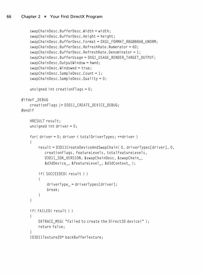
swapChainDesc.BufferDesc.Width = width;swapChainDesc.BufferDesc.Height = height;swapChainDesc.BufferDesc.Format = DXGI_FORMAT_R8G8B8A8_UNORM;swapChainDesc.BufferDesc.RefreshRate.Numerator = 60;swapChainDesc.BufferDesc.RefreshRate.Denominator = 1;swapChainDesc.BufferUsage = DXGI_USAGE_RENDER_TARGET_OUTPUT;swapChainDesc.OutputWindow = hwnd;swapChainDesc.Windowed = true;swapChainDesc.SampleDesc.Count = 1;swapChainDesc.SampleDesc.Quality = 0;
unsigned int creationFlags = 0;
#ifdef _DEBUGcreationFlags |= D3D11_CREATE_DEVICE_DEBUG;
#endif
HRESULT result;unsigned int driver = 0;
for( driver = 0; driver < totalDriverTypes; ++driver ){
result = D3D11CreateDeviceAndSwapChain( 0, driverTypes[driver], 0,creationFlags, featureLevels, totalFeatureLevels,D3D11_SDK_VERSION, &swapChainDesc, &swapChain_,&d3dDevice_, &featureLevel_, &d3dContext_ );
if( SUCCEEDED( result ) ){
driverType_ = driverTypes[driver];break;
}}
if( FAILED( result ) ){
DXTRACE_MSG( "Failed to create the Direct3D device!" );return false;
}ID3D11Texture2D* backBufferTexture;
66 Chapter 2 n Your First DirectX Program

result = swapChain_->GetBuffer( 0, __uuidof( ID3D11Texture2D ),( LPVOID* )&backBufferTexture );
if( FAILED( result ) ){
DXTRACE_MSG( "Failed to get the swap chain back buffer!" );return false;
}
result = d3dDevice_->CreateRenderTargetView( backBufferTexture, 0,&backBufferTarget_ );
if( backBufferTexture )backBufferTexture->Release( );
if( FAILED( result ) ){
DXTRACE_MSG( "Failed to create the render target view!" );return false;
}
d3dContext_->OMSetRenderTargets( 1, &backBufferTarget_, 0 );
D3D11_VIEWPORT viewport;viewport.Width = static_cast<float>(width);viewport.Height = static_cast<float>(height);viewport.MinDepth = 0.0f;viewport.MaxDepth = 1.0f;viewport.TopLeftX = 0.0f;viewport.TopLeftY = 0.0f;
d3dContext_->RSSetViewports( 1, &viewport );
return LoadContent( );}
The Blank Window Demo Class
Currently we have everything needed to run the Blank Direct3D Window demo.To do this we’ll derive a class from the Dx11DemoBase class and call itBlankDemo. The BlankDemo class definition can be seen in Listing 2.16.
The Blank D3D Window 67

Listing 2.16 The BlankDemo class header.
#ifndef _BLANK_DEMO_H_#define _BLANK_DEMO_H_
#include"Dx11DemoBase.h"
class BlankDemo : public Dx11DemoBase{
public:BlankDemo( );virtual ~BlankDemo( );
bool LoadContent( );void UnloadContent( );
void Update( float dt );void Render( );
};
#endif
The Update function takes a single parameter called dt. We’ll look at this valuemore closely in Chapter 3, but for now understand that in games we often needto update logic based on real time. The dt parameter will represent the timedelta that has passed since the last frame, and we’ll use it for time-based updates.For now we’ll ignore it until we discuss animation.
Since the demo does not do anything special but clears the screen usingDirect3D, all of the overridden functions are empty, with the exception of theRender function. In the Render function we only call two Direct3D functions. Wefirst call ClearRenderTargetView to clear the screen to a specified color, and thenwe call Present to display that newly rendered scene (or lack thereof, since therender was just a uniform color). It is all pretty basic and made even easier tounderstand since all of the Direct3D functions used throughout this demo havealready been discussed in great detail earlier in the chapter. The BlankDemoimplemented member functions can be seen in Listing 2.17, in case you’refollowing along by writing code as you read.
68 Chapter 2 n Your First DirectX Program

Listing 2.17 The implementation of the BlankDemo class.
#include"BlankDemo.h"
BlankDemo::BlankDemo( ){
}
BlankDemo::~BlankDemo( ){
}
bool BlankDemo::LoadContent( ){
return true;}
void BlankDemo::UnloadContent( ){
}
void BlankDemo::Update( float dt ){
}
void BlankDemo::Render( ){
if( d3dContext_ == 0 )return;
float clearColor[4] = { 0.0f, 0.0f, 0.25f, 1.0f };
The Blank D3D Window 69
d3dContext_->ClearRenderTargetView( backBufferTarget_, clearColor );
swapChain_->Present( 0, 0 );}
Updating the Application Loop
Currently we have everything needed to bring the Blank Direct3D Windowdemo to life. The last and final step is updating the wWinMain function we createdin the first demo of this chapter (the Blank Win32 Window demo) to use ourdemo class. Remember when we only had comments set as placeholders wherewe would add our Direct3D code? In Listing 2.18 you get to see where thosecomments were removed and replaced with their corresponding function calls.
Listing 2.18 The main source file of the Blank Direct3D Window demo.
#include<Windows.h>#include<memory>#include"BlankDemo.h"
LRESULT CALLBACK WndProc( HWND hwnd, UINT message, WPARAM wParam, LPARAM lParam);
int WINAPI wWinMain( HINSTANCE hInstance, HINSTANCE prevInstance,LPWSTR cmdLine, int cmdShow )
{UNREFERENCED_PARAMETER( prevInstance );UNREFERENCED_PARAMETER( cmdLine );
WNDCLASSEX wndClass = { 0 };wndClass.cbSize = sizeof( WNDCLASSEX ) ;wndClass.style = CS_HREDRAW | CS_VREDRAW;wndClass.lpfnWndProc = WndProc;wndClass.hInstance = hInstance;wndClass.hCursor = LoadCursor( NULL, IDC_ARROW );wndClass.hbrBackground = ( HBRUSH )( COLOR_WINDOW + 1 );wndClass.lpszMenuName = NULL;wndClass.lpszClassName = "DX11BookWindowClass";
70 Chapter 2 n Your First DirectX Program

if( !RegisterClassEx( &wndClass ) )return -1;
RECT rc = { 0, 0, 640, 480 };AdjustWindowRect( &rc, WS_OVERLAPPEDWINDOW, FALSE );
HWND hwnd = CreateWindowA( "DX11BookWindowClass", "Blank Direct3D 11Window",
WS_OVERLAPPEDWINDOW, CW_USEDEFAULT, CW_USEDEFAULT, rc.right - rc.left,rc.bottom - rc.top, NULL, NULL, hInstance, NULL );
if( !hwnd )return -1;
ShowWindow( hwnd, cmdShow );
std::auto_ptr<Dx11DemoBase> demo( new BlankDemo( ) );
// Demo Initializebool result = demo->Initialize( hInstance, hwnd );
// Error reporting if there is an issueif( result == false )
return -1;
MSG msg = { 0 };
while( msg.message != WM_QUIT ){
if( PeekMessage( &msg, 0, 0, 0, PM_REMOVE ) ){
TranslateMessage( &msg );DispatchMessage( &msg );
}else{
// Update and Drawdemo->Update( 0.0f );demo->Render( );
}
The Blank D3D Window 71

}
// Demo Shutdowndemo->Shutdown( );
return static_cast<int>( msg.wParam );}
LRESULT CALLBACK WndProc( HWND hwnd, UINT message, WPARAM wParam, LPARAM lParam ){
PAINTSTRUCT paintStruct;HDC hDC;
switch( message ){
case WM_PAINT:hDC = BeginPaint( hwnd, &paintStruct );EndPaint( hwnd, &paintStruct );break;
case WM_DESTROY:PostQuitMessage( 0 );break;
default:return DefWindowProc( hwnd, message, wParam, lParam );
}
return 0;}
We’ve added seven lines of code to the wWinMain function. First we’ve created thedemo instance by using the C++ standard smart pointer auto_ptr<>. Theauto_ptr<> smart pointer is one that automatically deletes the memory it ispointing to when the scope it is in ends or when it is copied to anotherauto_ptr<>. The scope can be function level, within an if-statement, inside aloop, and within a pair of curly braces arbitrarily placed to create a new scope.
The benefit to this is that we don’t need to manually delete the allocated data.The true benefit that goes beyond that (since it would not be hard or even
72 Chapter 2 n Your First DirectX Program
unlikely to just call delete on the demo object) is that using auto_ptr<> isexception safe. This means that even if an exception is triggered and yourapplication halts, the auto_ptr<> will still release its data during stack unwind-ing. This means no leaks, even when the application crashes. If we manually hadto delete this pointer and if execution did halt, we’d be left with leaked memory.There are tons of benefits to using memory objects such as auto_ptr<>. If youare unfamiliar with them it is important to read up on smart pointers and otherstandards offered by the C++ programming language that are beyond the scopeof this book. If you have not brushed up on the recent standard of C++ (C++0x),it is recommended you do so.
The last thing to note in the wWinMain function is that we are returning thewParam member of the MSG object in order to return the application’s exit code.Since wWinMain returns an integer, we cast this object to an integer by usingC++’s static_cast<> operator.
A screenshot of the Blank Direct3D Window can be seen in Figure 2.8. Thedemo is using a dark color to clear the screen, which should be reflected in thescreenshot when compared to the earlier Blank Win32 Window demo.
The completion of the Blank Direct3D Window demo marks the completion ofthe template files we’ll use throughout this book to create future demos. Tocreate the future demos, we just need to derive new classes from Dx11DemoBaseand implement the demo-specific logic we need by overriding LoadContent,UnloadContent, Update, and Render.
DirectX Error Handling Library
The DirectX SDK comes with a series of utility functions and macros that aid inthe debugging of DirectX applications. To gain access to these utilities, projectsmust link to Dxerr.lib and include the Dxerr.h header file. In this section we willdiscuss the various error handling functions and macros that exist.
Error Handling Functions
There are three functions in the DirectX Error Handling library:
n TCHAR* DXGetErrorDescription( HRESULT hr )
n TCHAR* DXGetErrorString( HRESULT hr )
DirectX Error Handling Library 73

n HRESULT DXTrace( CHAR * strFile, DWORD dwline, HRESULT hr, CHAR *
strMsg, BOOL bPopMsgBox )
The function DXGetErrorDescription takes any HRESULT return value and returnsa string storing the description of that error.
The function DXGetErrorString also takes any HRESULT error value but returns astring holding the error code. For example, “D3DERR_DEVICELOST” will bereturned for a value matching that error code, while DXGetErrorDescription
returns the description of what that actually means.
The last function, DXTrace, will display a message with the error string fromDXGetErrorString. This function takes as parameters the current file (you can usethe Win32 __FILE__ macros for this parameter), the line number (you can usethe Win32 macro __LINE__), the HRESULT holding the error value, a pointer toan optional string message that will be displayed along with the file and line, anda Boolean specifying if the trace should display a pop-up message box.
Figure 2.8
The Blank D3D Window demo screenshot.
74 Chapter 2 n Your First DirectX Program

Error Handling Macros
There are three main error handling macros to be aware of, and to fully utilizethem you must be running the application in the debugger. These error handlingmacros include the following, which are related to the DXTrace function:
n DXTRACE_ERR( str, hr )
n DXTRACE_ERR_MSGBOX( str, hr )
n DXTRACE_MSG( str )
The DXTRACE_ERR macro is used to output a message to the debugger, where str
is a string you want displayed along with the tracing information and theHRESULT value of the error result. The DXTRACE_ERR_MSGBOX is essentially DXTRA-
CE_ERR but will display the output using a message box pop-up. The final macro,DXTRACE_MSG, takes a single parameter, which is the string to display to theoutput debugger window. The file and line appear with the string parameterwith each of these macros.
Throughout this chapter we’ve focused mostly on using DXTRACE_MSG to displayerrors when they occur during our Direct3D setup. It is important to be aware ofthese macros, as they can be very useful when building and debugging DirectXapplications.
Summary
This chapter covered how to set up and create a Direct3D 11 window usingVisual Studio 2010. We’ve ended this chapter with a set of template files that wecan use for the rest of the demos throughout this book. If you’re coming toDirect3D 11 from Direct3D 9 or below, you can appreciate how easy it is to getDirect3D up and running. Although it took a number of lines of code, thoselines of code were fairly straightforward and easy to digest.
In the next chapter we will begin rendering 2D geometry to the screen, alongwith discussing the topic of texture mapped images. We will build off the codedeveloped throughout this chapter; therefore it is important to have a solidunderstanding of each of the Win32 and DirectX functions as well as how thecode template works.
Summary 75

Chapter Questions
Answers to the following chapter review questions can be found in Appendix Aon this book’s companion website.
1. Which of the following is a Direct3D device type?
A. Hardware
B. Software
C. WARP
D. Both A and B
E. All of the above
2. The viewport does what?
A. Draws to the monitor
B. Defines the area of the window that is drawn to
C. Is a 3D camera
D. None of the above
3. What are swap chains?
A. Another name for a Direct3D device
B. Another name for a Direct3D context
C. Both A and B
D. A collection of rendering destinations displayed to the screen
4. Presenting the rendered scene is done with the Present method. Which objectdoes Present belong to?
A. Swap chains
B. Direct3D device
C. Direct3D context
D. Render target view
76 Chapter 2 n Your First DirectX Program

5. What are render targets?
A. An object used to render geometry
B. A texture that is the destination of a rendering output
C. Another name for a swap chain
D. None of the above
6. What feature levels did the Blank Window demo support?
A. Direct3D 11
B. Direct3D 10
C. Direct3D 9
D. Both A and B
E. Both A and B and Direct3D 10.1
F. All of the above
7. What is a WARP device?
A. A fast hardware-rendering device.
B. A down-level hardware-rendering device
C. A fast software-rendering device
D. None of the above
8. How are Direct3D objects freed?
A. Calling delete on them like C++ dynamically located objects
B. Calling the COM object’s Release method
C. They are automatically released upon the application’s exit
D. Use an auto_ptr<>
9. How can we create a full-screen Direct3D window?
A. Setting the window’s width and height to a resolution larger than thescreen
Chapter Questions 77

B. Can only be done in hardware device mode
C. Must use a special Direct3D context creation device for full-screenapplications
D. Set the Windowed property of the swap chain description to false
10. What is the purpose of the DirectX Error Handling Library?
A. Debug output
B. Used to create exception-safe code
C. Fixes errors at run-time
D. Similar to C++ try/catch but for the graphics card
11. True or False: auto_ptr<> is exception safe
A. True
B. False
12. True or False: WinMain has Unicode parameters
A. True
B. False
13. True or False: The operator dynamic_cast<> offers run-time safety
A. True
B. False
14. True or False: The operator static_cast<> is used to cast static variables
A. True
B. False
15. True or False: DXTRACE_MSG displays a string to a message box
A. True
B. False
78 Chapter 2 n Your First DirectX Program

2D Rendering
Two-dimensional (2D) games, immensely popular in the early days of videogames, have had a huge revival in recent years. Due to the relative ease ofdevelopment, thousands of independent (indie) and professional games arebeing brought to life using 2D rendering techniques. Using Microsoft’s XboxLive Arcade as an example, a number of the most popular games available arestrictly 2D, such as Geometry Wars 2 and Scott Pilgrim vs. The World. Inaddition, web games based on Adobe Flash, Microsoft Silverlight, and theHTML 5 standard, along with mobile devices such as the iPhone and Android-based phones, are also home to many 2D games. Developers are quickly beingreminded that games don’t have to have the most expensive budgets or the latest3D technology; they just have to be fun. 2D games are as relevant today as theyalways were.
In this chapter:
n How to take advantage of 2D techniques needed to build a game
n What textures are and how they can be used
n An easy way to load in a texture image
n How to create and use sprites
Chapter 3
79

2D Game Development
2D games take place in a grid-like area whose space is comprised of only widthand height. Using a real-world example of a grid, it is like a piece of grid paperused during math classes in most elementary and middle schools. In gamegraphics, objects are placed on this invisible grid by specifying their X and Y axislocations, but in the 2D game universe this space is infinite. Figure 3.1 shows anexample of this 2D grid and objects placed within it. The 2D area of a grid is alsoknown as the grid’s plane, where a plane is a 2D area that stretches to infinity.
In 3D games the grid still exists, but instead of just the X and Y axes, there is alsothe Z axis for depth. Visually we can think of this grid as a cube instead of asquare, where the cube has an infinite number of 2D planes stacked on top ofeach other for its depth. These planes are infinitely thin slices of space that makeup the virtual universe. A visual example of a 3D grid can be seen in Figure 3.2.
Mathematically, the requirements of a 2D game and a 3D game are like nightand day, due mostly to both the simulation (e.g., physics, collisions, animations,etc.) and the rendering techniques used to shade the surfaces. In addition tohaving more complex math operations for the various effects, animations, andgeometric objects, 3D games also have a ton more assets such as textures andgeometry that far surpass what is seen in 2D games in terms of numbers andmemory requirements. But even though 2D games tend to have differentrequirements in general (e.g., development manpower, storage, CPU cycles,
Figure 3.1
An example of a 2D grid.
80 Chapter 3 n 2D Rendering

hardware requirements, etc.), it is still challenging to create a professional-quality 2D game.
In 2D games we generally have the following pieces of information common tothe rendering portions of a game, each of which will be highlighted throughoutthis chapter:
n Textures
n Sprites
Textures
A texture is a core piece of any game, be it 2D or 3D. A texture is another namefor an image that is mapped over a surface, usually to give that surface theappearance of having a more complex makeup than it really has.
Take for example a brick wall. Instead of modeling out a brick wall with all itsnooks and crannies, chips, and other defects that make the look of bricks in anenvironment realistic, it is far more efficient to use a simple square shape andhave the image of a brick wall displayed over it. This is, after all, why texturesexist, and their purpose in computer graphics is to simulate complex surfaceswhere this complexity does not actually exist in the geometric sense.
A square with the image of a brick wall does not have anywhere near thegeometric complexity of a 3D wall with modeled bricks. In fact, we can be talking
Figure 3.2
An example of a 3D grid.
2D Game Development 81
about two triangles versus several thousand or even millions. To take it a stepfurther, we can even simulate the change of light as it interacts with this smallsimulated detail by combining texture mapping with another technique knownas normal mapping.
No t e
Video game graphics are all about shading and simulating effects. Textures are used to simulatecomplexity on the per-pixel level that does not actually exist for the surface.
There are many different types of textures common in video games, most ofwhich are found in 3D games. These types of textures commonly include thefollowing:
n Color maps (sometimes referred to as decal maps and used for coloringsurfaces).
n Specular maps (also known as gloss maps and used for maskinghighlights).
n Light maps (prerendered lights and/or shadows stored in textures).
n Ambient occlusion maps (advanced lighting topic that moves toward therealm of global illumination).
n Shadow maps (used during real-time shadow generation and rendering).
n Height maps (used for a variety of reasons, usually displacement ofgeometry to deform its shape).
n Normal maps (used during per-pixel lighting to simulate high-complexitygeometry on low-resolution geometry as far as lighting and the view’sperspective is concerned).
n Alpha maps (used for transparency).
n Cube maps (commonly used for reflections and environment lighting).
n And many more.
An example of a color texture image being created in Photoshop can be seen inFigure 3.3. As you can see in the list of texture types, most textures are not usedfor color information, and a lot of them have to do with lighting and shadowing.
82 Chapter 3 n 2D Rendering

Technically, even those used for lighting are actually what we would call a look-up texture, where the texture is used to store values on the per-pixel level that isused for some algorithm that takes place during the rendering pipeline—whichis not necessarily lighting but can be for any purpose. For example, a height mapbeing used for displacement is used to deform the geometry, not shade it. Acolor map is used to shade the surface with a solid color, whereas the look-uptextures used during lighting are used to alter this solid color based on lightingproperties in the environment.
No t e
A look-up texture allows us to store values for a pixel that can be used for “some” algorithm,whether it is to look up the color value of the pixel, some value used during the lightingcalculations, etc.
Figure 3.3
An example of a texture created in Photoshop.
2D Game Development 83

In 2D games, out of the list above, we’ll mostly deal only with color map texturesand alpha maps, since the rest of the items on the list deal mostly with lighting,which is a 3D topic. Since 32-bit images have an alpha channel, the alpha mapdoes not need to be a separate image on today’s hardware. We’ll revisit textureslater in this chapter during the section titled “Texture Mapping.” The alphachannel of an image is used to specify the transparency (opacity) of each pixel inthe image.
Sprites
A sprite is a special type of object. The word sprite is used to refer to a 2Dgraphical element that appears on the screen. Sprites are not just used in 2Dgames but also in 3D games. For 3D, sprites are used for the graphical elementsof the heads-up display (e.g., the health bar, timers, armor levels, etc.) as well asparticles and effects and more. An example of 2D elements being used in 3Dgames can be seen in Figure 3.4, Figure 3.5, and Figure 3.6.
In Figure 3.5 the particles from the ParticlesGS demo from the DirectX SDKuses sprites that are always facing the camera to hide the fact that they are flat. InFigure 3.6 multiple sprites are used together to create the smoke effect in theSoftParticles DirectX SDK demo. Since these sprites use composition andtransparency, it is sometimes hard to see the individual elements with thenaked eye, even if the camera has a close-up of the sprites. In Figure 3.6 the left
Figure 3.4
2D elements being rendered on top of the action in the DirectX SDK’s Pipes GS demo.
84 Chapter 3 n 2D Rendering

and right views show how the sprite smoke is always facing the camera, even asthe camera moves around it. This is known as a billboard sprite.
No t e
A billboard sprite is a sprite that is always facing the camera, regardless of changes in the camera’sorientation.
Figure 3.5
Sprites used within a particle system in the ParticlesGS DirectX SDK demo.
Figure 3.6
A close look at how transparent particles are used to create smoke in the SoftParticles DirectX SDKdemo.
2D Game Development 85

A sprite is essentially a textured 2D shape, like a rectangle or square. In 2Dgames, sprites are used not only for characters but also for backgrounds, gameobjects, weapons, and every single element or item that can be drawn. Anexample can be seen in the Role Playing Game Starter Kit sample, available forMicrosoft’s XNA Game Studio Express (Figure 3.7) where the characters,props, backgrounds, etc. are all sprites that come together to create the scene.
Animations in 2D are performed by taking a series of sprites and displayingthem one at a time in rapid succession. This is similar to a flip book or howcartoon animations operate by displaying frames of animation where each frameshows an instance of the animation being displayed. Developers of 2D gamesoften use what are known as sprite sheets, which are large images that contain allframes of animation for a particular sprite.
2D Geometry
Understanding how to create and manipulate geometry is critical to masteringvideo game graphics. What we see on the screen is a fine combination of art andmath that works together to create the simulation our gamers enjoy. Fornewcomers to game graphics, this section will serve as a brief introduction to
Figure 3.7
A 2D game made of sprites (XNA's Role Player Game Starter Kit).
86 Chapter 3 n 2D Rendering

the basics of 2D geometry and Direct3D rendering. Although Direct3D is largelyassociated with 3D graphics, it is also capable of rendering 2D graphics via thegraphics hardware.
What Is a Vertex?
Shapes are defined in game graphics as a collection of points connected togethervia lines whose insides are shaded in by the graphics hardware. These points arereferred to as vertices (the plural term for a vertex), and these lines are referredto as edges. A shape is referred to as lines if it has two connected points or aspolygons if it has three or more connected points. As you move on to moreadvanced rendering topics (beyond the scope of this book), you’ll undoubtedlycome across each of these terms often. See Figure 3.8 for an example of each ofthese terms.
Vertices are not technically drawn but instead provide the graphics hardwarewith information necessary to mathematically define a surface for rendering. Ofcourse, it is possible to render points with the Direct3D API and use the positionof a vertex as the point’s position, but in reality a vertex is a unit of data used bythe graphics card, along with other data, to define attributes of a larger shape.Although a vertex and a point are not the same thing, they both share having aposition in common.
A vertex is more than a point. A vertex is actually a series of attributes thatdefines a region of the shape. In fact, the points in Figure 3.8 could actually referto vertices of a triangle being passed to Direct3D for rendering where each
Figure 3.8
The breakdown of a triangle.
2D Geometry 87
vertex has a host of information the shaders will need to produce an effect. Weuse vertices to mathematically define the shape, and the graphics hardware usesthese properties to draw the shape being specified, where all of the propertiesprovided depend on the graphics effect being shaded. Common properties of avertex that we will discuss throughout this book include:
n Position
n Color
n Normal vector
n Texture coordinate(s)
Other properties that are common in video games include but are not limited tothe following:
n S-tangent (usually used during normal mapping)
n Bi-normal (also often used for normal mapping)
n Bone weights and indices (used for skeleton animation)
n Light map coordinates
n Per-vertex ambient occlusion factor
n And much more
The position of a vertex is the only property of a vertex that is not optional.Without a position we cannot define a shape, which means Direct3D cannotdraw anything to any of its buffers. A 2D vertex has X and Y values for itsposition, whereas a 3D vertex has X, Y, and Z values. Most of the time we definethe position first and all other properties after it. These properties ultimatelydepend on what per-vertex data is needed to create a specific rendering effect.For example, texture coordinates are necessary for producing a UV texturemapping effect just like bone animation information is necessary for performinganimations within the vertex shader.
Many rendering effects work from per-pixel data instead of per-vertex data, suchas per-pixel lighting and normal mapping. But remember that we don’t specifyper-pixel data in the form of geometry, so this per-pixel data is calculated usinginterpolation. Interpolation is the generation of intermediate values between one
88 Chapter 3 n 2D Rendering

point and the next. Taking the pixel shader as an example: It receives interpolateddata from the vertex shader (or geometry shader if one is present). Thisinterpolated data includes positions, colors, texture coordinates, and all otherattributes provided by the previous shader stage. As the pixel shader is invokedby the graphics hardware, the pixels that fall within the shape are shaded.
When we do specify per-pixel data, it is often in the form of texture images, suchas a normal map texture used to provide per-pixel level normal vectors to alterlighting on a more micro-level to simulate higher amounts of detail across ashape. Another example is the classic texture mapping, which is used to provideper-pixel color data used to shade the surface of a shape.
On a side note, a normal vector (which we’ll dive deeper into in Chapter 6) is adirection. Keep in mind that a vertex is a collection of attributes for a point of ashape, whereas a vector is an X and Y axis direction for 2D vectors and an X, Y,and Z direction for 3D vectors. Sometimes you’ll see the terms used interchange-ably, but it is important to know that they are not the same. This happens mostlybecause, code-wise, a vertex defines just a position, and a vector is essentially thesame and is only different in what it represents in the context you are using it.An example is as follows:
struct Vertex2D{
float X;float Y;
};
struct Vector2D{
float X;float Y;
};
In some cases the difference between a vertex with only a position attribute and avector really lies in our interpretation of the data, and either structure can be usedfor either purpose as long as we are being consistent. For example a vectorpointing in the direction a bullet is traveling is different from the bullet’s actualposition at any point in time, but in code both a 3D vertex’s position and a 3D
2D Geometry 89
vector are both X, Y, and Z floating-point values. Also, a vector with a magnitudeof 1 is known as a unit-length vector, which we’ll discuss more in Chapter 6.
In Direct3D we even have vector structures that we can use with the XNA Mathlibrary. Usually most programmers will use the vector structure to define theposition of the vertex, even though a vector is not necessarily a position per se.This is very common, and it is important to be aware of this little tidbit. A vectorused in this manner can be considered a direction from the virtual world’s origin(or even another frame of reference) at which the vertex is located. Since theorigin is usually 0 for the X, Y, and Z in 3D space, this vector direction happensto equal the relative or absolute position of the point and hence can be usedinterchangeably. An example of using vectors to define attributes of a vertex thatuses X, Y, and Z values is as follows:
struct Vector2D{
float X;float Y;
};
struct Vector3D{
float X;float Y;float Z;
};
struct Vertex3D{
Vector3D position;Vector3D normal;Vector2D textureCoordinate;
};
As you can see, even though a vector is not a point, it can be used as if it were aposition, since the direction from the origin located at (0, 0, 0) will equal a vectorwith the same values as a point’s position. In other words, the context in which avector is used determines what it ultimately represents.
90 Chapter 3 n 2D Rendering

Definition of a Triangle
If we define a polygon as a shape with three or more vertices, then the polygon withthe smallest number of vertices is a triangle. Traditionally we think of a triangle as ashape being made up of three points, such as what is shown in Figure 3.8.
In game graphics we can define an array of these triangles where each triangle isits own independent shape. A collection of triangles is what we use to definemeshes, where a mesh is defined as an object made up of a bunch of polygons. Acollection of meshes creates a model, where a model is defined as one or moremeshes. An example of a mesh can be a head shape of a 3D character, whereasthe head, torso, legs, and other body parts (meshes) make up the entire charactermodel. These terms are highly important to understand when learning gamegraphics. An example can be seen in Figure 3.9 (a mesh being a collection oftriangle polygons) and Figure 3.10 (several meshes together forming a model).
An array of individual triangles is known as a triangle list, but there are othertypes of triangles, known as a triangle strip and triangle fan. A triangle strip is anarray, where the first three vertices define the first triangle and the fourth vertex,
Figure 3.9
A mesh.
2D Geometry 91
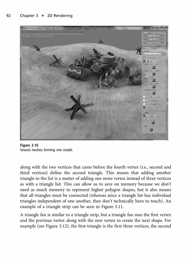
along with the two vertices that came before the fourth vertex (i.e., second andthird vertices) define the second triangle. This means that adding anothertriangle to the list is a matter of adding one more vertex instead of three verticesas with a triangle list. This can allow us to save on memory because we don’tneed as much memory to represent higher polygon shapes, but it also meansthat all triangles must be connected (whereas since a triangle list has individualtriangles independent of one another, they don’t technically have to touch). Anexample of a triangle strip can be seen in Figure 3.11.
A triangle fan is similar to a triangle strip, but a triangle fan uses the first vertexand the previous vertex along with the new vertex to create the next shape. Forexample (see Figure 3.12), the first triangle is the first three vertices, the second
Figure 3.10
Several meshes forming one model.
92 Chapter 3 n 2D Rendering

triangle is the first vertex, the third vertex, and the fourth vertex, and the thirdtriangle is the first vertex, the fourth vertex, and the fifth vertex.
Another representation we must discuss for polygons is the use of indexedgeometry. Index geometry refers to using only unique vertices for the vertex listand using array indexes into that list to define which points make up whichtriangles. For example, the cube object in Figure 3.9 technically has only eightunique vertices, with one vertex appearing in each corner of the cube. If we useda triangle list we’d have many overlapping vertices along the end points of thecube, causing us to define a vertex list of 36 vertices (3 vertices per triangle�2 triangles per side� 6 sides = 36).
The main benefit from using index geometry comes from models with hundreds,thousands, or more polygons. For these models there will usually be a very highnumber of triangles that share the same edges with one another. Remember thatan edge is the line between two connecting vertices, and triangles have threeedges in total. If our index geometry uses 16-bit values for the indices, then atriangle can be defined by using three 16-bit integers, which equals 48 bits
Figure 3.11
An example of a triangle strip.
Figure 3.12
An example of a triangle fan.
2D Geometry 93

(which equals 6 bytes). Compare this to a 3D vertex that has three floating-pointvalues at 4 bytes per axis, giving us 12 bytes per vertex and 36 bytes per triangle.Since indexed geometry includes the vertex list of unique vertices, we won’t seeany savings until the polygon count has reached a high enough count to whereadding more triangles is cheaper memory-wise using indices than it is byspecifying more independent triangles. As the polygon count rises, so does thedifference in memory consumed by a model using indexed geometry and onethat uses triangle lists. We’ll revisit this discuss in Chapter 6 when we discuss 3Dgeometry in more detail.
Vertex Buffers
A buffer is memory of a specific size. If you have an array of 100 chars, then youcan say you have a buffer that is 100 bytes in size. If instead of chars we weretalking about integers, then you could say you have a buffer of integers, wherethe buffer is 400 bytes in size (integer = 4 bytes� 100 integers = 400 bytes).When dealing with Direct3D, we create buffers for many different reasons, butthe first reason we’ll discuss is the creation of what are known as vertex buffers.
A vertex buffer is a Direct3D buffer of the type ID3D11Buffer that is used to store allthe vertex data for a mesh. When we create a vertex buffer in Direct3D we arecreating an object that resides in an optimal location of memory, such as videomemory of the graphics hardware, which is chosen by the device driver. WhenDirect3D renders our objects, it transfers this information across the graphics busand performs the necessary operations throughout the rendering pipeline thatultimately causes that geometry to be rendered onscreen or not. We say “or not”because geometry can ultimately be determined by Direct3D as not being visible.Attempting to render a ton of geometry that is not visible can lead to negativeperformance, and most advanced 3D commercial video games use techniques todetermine what geometry is visible beforehand and only submit those that areeither visible or potentially visible to the graphics hardware. This is an advancedtopic and usually falls within scene management and deals with many topics knownas culling and partitioning algorithms. The fastest geometry to draw is geometryyou don’t draw at all, and this is one of the keys for next-generation games.
Let’s take a look at the creation of a vertex buffer. Let’s assume we are definingvertices that specify only a positional attribute such as the following:
94 Chapter 3 n 2D Rendering

struct VertexPos{
XMFLOAT3 pos;};
XMFLOAT3 is a structure with X, Y, and Z floating-point values within. The namedefines what the structure represents, where the XM refers to XNA Math, FLOATrefers to the data type of the structure’s members, and 3 refers to how manymembers the structure has. This structure can be used for 3D points, 3D vectors,etc., and again what it represents depends on the context in which you use it.Direct3D 11 uses the XNA Math library, whereas previous versions of Direct3Dwould have used D3DXVECTOR3 for this purpose. Direct3D has long sinceprovided us with a highly optimized math library, so we don’t have to write oneourselves, but we will cover the details and the math of these common structuresand operations in Chapter 6.
Assuming we have a valid Direct3D device created, we could create a vertexbuffer with a simple triangle using the following code as an example:
VertexPos vertices[] ={
XMFLOAT3( 0.5f, 0.5f, 0.5f ),XMFLOAT3( 0.5f, -0.5f, 0.5f ),XMFLOAT3( -0.5f, -0.5f, 0.5f )
};
D3D11_BUFFER_DESC vertexDesc;ZeroMemory( &vertexDesc, sizeof( vertexDesc ) );
vertexDesc.Usage = D3D11_USAGE_DEFAULT;vertexDesc.BindFlags = D3D11_BIND_VERTEX_BUFFER;vertexDesc.ByteWidth = sizeof( VertexPos ) * 3;
D3D11_SUBRESOURCE_DATA resourceData;ZeroMemory( &resourceData, sizeof( resourceData ) );resourceData.pSysMem = vertices;
ID3D11Buffer* vertexBuffer;HRESULT result = d3dDevice_->CreateBuffer( &vertexDesc, &resourceData,
&vertexBuffer );
2D Geometry 95

First you’ll notice we define the vertex list, which has three vertices that define asingle triangle. Next we create the buffer descriptor object. The buffer descriptor,of the type D3D11_BUFFER_DESC, is used to provide the details of the buffer we arecreating, which is important since technically we could be creating another typeof buffer other than a vertex buffer. The buffer description has the followingstructure and members:
typedef struct D3D11_BUFFER_DESC {UINT ByteWidth;D3D11_USAGE Usage;UINT BindFlags;UINT CPUAccessFlags;UINT MiscFlags;UINT StructureByteStride;
} D3D11_BUFFER_DESC;
Next we create a sub resource. Sub resources are used in this case for us to passthe vertex data to the buffer’s creation function so that the buffer is filled withthis data. We optionally can pass null for the data, which will create an emptybuffer, but in this case we already know what data we want to store in the buffer,and the use of a D3D11_SUBRESOURCE_DATA object allows us to do that. TheD3D11_SUBRESOURCE_DATA has the following structure and members:
typedef struct D3D11_SUBRESOURCE_DATA {const void* pSysMem;UINT SysMemPitch;UINT SysMemSlicePitch;
} D3D11_SUBRESOURCE_DATA;
The pSysMem member of the D3D11_SUBRESOURCE_DATA structure is the pointer tothe initialized memory, or in our case the memory we are sending to fill thebuffer with. The SysMemPitch and SysMemSlicePitch are used for texture images,where SysMemPitch is used to determine where the beginning of one line of atexture to the next line is, and SysMemSlicePitch is used to determine one depthline to the next, which is used for 3D textures.
With the buffer descriptor and the sub-resource data we can create the buffer bysimply calling a single Direct3D device function called CreateBuffer. CreateBufferhas the following function prototype and takes as parameters the buffer descrip-tion, the sub-resource data (optionally), and the pointer for the ID3D11Buffer
object that will be created as our vertex buffer, as defined by the descriptor.
96 Chapter 3 n 2D Rendering
HRESULT CreateBuffer(const D3D11_BUFFER_DESC* pDesc,const D3D11_SUBRESOURCE_DATA* pInitialData,ID3D11Buffer** ppBuffer
);
If CreateBuffer succeeds, we can draw the geometry in the buffer at any point.
Input Layout
When we send geometry to the graphics card we are sending it a chunk of data.In order for Direct3D to know what the various attributes defined are, theirordering, and size, we use what is known as the input layout to tell the API aboutthe data’s vertex layout of the geometry we are about to draw.
In Direct3D we use an array of D3D11_INPUT_ELEMENT_DESC elements to describethe vertex layout of a vertex structure. The D3D11_INPUT_ELEMENT_DESC structurehas the following elements:
typedef struct D3D11_INPUT_ELEMENT_DESC {LPCSTR SemanticName;UINT SemanticIndex;DXGI_FORMAT Format;UINT InputSlot;UINT AlignedByteOffset;D3D11_INPUT_CLASSIFICATION InputSlotClass;UINT InstanceDataStepRate;
} D3D11_INPUT_ELEMENT_DESC;
The first member, the semantic name, is a string that describes the purpose ofthe element. For example one element will be the vertex’s position, and thereforeits semantic will be “POSITION”. We could also have an element for the vertex’scolor by using “COLOR”, a normal vector by using “NORMAL”, and so forth. Thesemantic binds the element to an HLSL shader’s input or output variable, whichwe’ll see later in this chapter.
The second member is the semantic index. A vertex can have multiple elementsusing the same semantic name but store different values. For example, if a vertexcan have two colors, then we can use a semantic index of 0 for the first color and1 for the second. More commonly, a vertex can have multiple texture coor-dinates, which can occur when UV texture mapping and light mapping arebeing applied at the same time, for example.
2D Geometry 97

The third member is the format of the element. For example for a position withX, Y, and Z floating-point axes, the format we would use for such a positionwould be DXGI_FORMAT_R32G32B32_FLOAT, where 32 bits (4 bytes) are reserved forthe R, G, and B components. Although the format has R, G, and B in its name, itcan be used as the X, Y, and Z. Don’t let the color notation throw you off to thefact that these formats are used for more than just colors.
The fourth member is the input slot, which is used to specify which vertex bufferthe element is found in. In Direct3D you can bind and pass multiple vertexbuffers at the same time. We can use the input slot member to specific the arrayindex of which vertex buffer this element is found in.
The fifth parameter is the aligned byte offset value, which is used to tell Direct3Dthe starting byte offset into the vertex buffer where it can find this element.
The sixth member is the input slot class, which is used to describe whether theelement is to be used for each vertex (per vertex) or for each instance (perobject). Per-object attributes deal with a more advanced topic known asinstancing, which is a technique used to draw multiple objects of the samemesh with a single draw call—a technique used to greatly improve renderingperformance where applicable.
The last member is the instance data step rate value, which is used to tellDirect3D how many instances to draw in the scene.
An input layout uses the type of ID3D11InputLayout. Input layouts arecreated with a call to the Direct3D device function CreateInputLayout. TheCreateInputLayout function has the following function prototype:
HRESULT CreateInputLayout(const D3D11_INPUT_ELEMENT_DESC* pInputElementDescs,UINT NumElements,const void* pShaderBytecodeWithInputSignature,SIZE_T BytecodeLength,ID3D11InputLayout** ppInputLayout
);
The first parameter to the CreateInputLayout function is the array of elementsin the vertex layout, while the second parameter is the number of elements inthat array.
98 Chapter 3 n 2D Rendering
The third parameter is the compiled vertex shader code with the input signaturethat will be validated against the array of elements, and the fourth element is thesize of the shader’s bytecode. The vertex shader’s input signature must matchour input layout, and this function call will fail if it does not.
The final parameter is the pointer of the object that will be created with thisfunction call.
A vertex shader is compiled code executed on the GPU. A vertex shader isexecuted for each vertex that’s processed by the device. There are varioustypes of shaders that Direct3D supports, each of which is discussed in moredetail in Chapter 7. Direct3D requires shaders for rendering geometry, andtherefore we must encounter them before we dive deep into their innerworkings.
Below is an example of creating a vertex shader, which we’ll need before we cancreate the input layout, since the vertex shader’s signature must match the inputlayout:
ID3D11VertexShader* solidColorVS;ID3D11PixelShader* solidColorPS;ID3D11InputLayout* inputLayout;
ID3DBlob* vsBuffer = 0;
DWORD shaderFlags = D3DCOMPILE_ENABLE_STRICTNESS;
#if defined( DEBUG ) || defined( _DEBUG )shaderFlags |= D3DCOMPILE_DEBUG;
#endif
ID3DBlob* errorBuffer = 0;HRESULT result;
result = D3DX11CompileFromFile( "sampleShader.fx", 0, 0, "VS_Main", "vs_4_0",shaderFlags, 0, 0, &vsBuffer, &errorBuffer, 0 );
if( FAILED( result ) ){
if( errorBuffer != 0 )
2D Geometry 99

{OutputDebugStringA( ( char* )errorBuffer->GetBufferPointer( ) );errorBuffer->Release( );
}
return false;}
if( errorBuffer != 0 )errorBuffer->Release( );
result = d3dDevice_->CreateVertexShader( vsBuffer->GetBufferPointer( ),vsBuffer->GetBufferSize( ), 0, &solidColorVS );
if( FAILED( result ) ){
if( vsBuffer )vsBuffer->Release( );
return false;}
To begin, we load the vertex shader from a text file and compile it into byte-code. You can optionally already have compiled byte code, or we can allowDirect3D to do it for us during startup, which is acceptable for the demosthroughout this book. Compiling a shader is done with a call to the D3DX11Com-
pileFromFile function. This function has the following prototype:
HRESULT D3DX11CompileFromFile(LPCTSTR pSrcFile,const D3D10_SHADER_MACRO* pDefines,LPD3D10INCLUDE pInclude,LPCSTR pFunctionName,LPCSTR pProfile,UINT Flags1,UINT Flags2,ID3DX11ThreadPump* pPump,ID3D10Blob** ppShader,ID3D10Blob** ppErrorMsgs,HRESULT* pHResult
);
100 Chapter 3 n 2D Rendering

The first parameter of the D3DX11CompileFromFile function is the path of theHLSL shader code to be loaded and compiled.
The second parameter is the global macros within the shader’s code. Macros in aHLSL shader work the same way they do in C/C++. An HLSL macro is definedon the application side using the type D3D_SHADER_MACRO and an example ofdefining a macro called “AGE”, and giving it the value of 18 can be seen asfollows:
const D3D_SHADER_MACRO defineMacros[] ={
"AGE", "18",};
The third parameter of the D3DX11CompileFromFile is an optional parameter forhandling #include statements that exist within the HLSL shader file. Thisinterface mainly is used to specify behavior for opening and closing files thatare included in the shader source.
The fourth parameter is the entry function name for the shader you arecompiling. A file can have multiple shader types (e.g., vertex, pixel, geometry,etc.) and many functions for various purposes. This parameter is important fortelling the compiler which of these potentially many functions serve as the entrypoint to the shader we are compiling.
The fifth parameter specifies the shader model. For our purposes we’ll beusing either vs_4_0 or vs_5_0 for vertex shader 4.0 or 5.0, respectively. Inorder to use shader model 5.0, you must have a DirectX 11–supportedgraphics unit, whereas to use shader model 4.0 you’ll need a DirectX 10and above graphics unit. We’ll cover shaders and shader models in moredetail in Chapter 7.
The sixth parameter of the D3DX11CompileFromFile is the compile flags for theshader code and is used to specify compile options during compilation. Thecompile flags are specified using the following macros:
n D3D10_SHADER_AVOID_FLOW_CONTROL—disables flow control wheneverpossible.
n D3D10_SHADER_DEBUG—inserts debugging information with the compiledshader.
2D Geometry 101
n D3D10_SHADER_ENABLE_STRICTNESS—disallows legacy syntax.
n D3D10_SHADER_ENABLE_BACKWARDS_COMPATIBILITY—allows older syntax tocompile to shader 4.0.
n D3D10_SHADER_FORCE_VS_SOFTWARE_NO_OPT—forces vertex shaders to com-pile to the next highest supported version.
n D3D10_SHADER_FORCE_PS_SOFTWARE_NO_OPT—forces pixel shaders to com-pile to the next highest supported version.
n D3D10_SHADER_IEEE_STRICTNESS—enables strict IEEE rules for compilation.
n D3D10_SHADER_NO_PRESHADER—disables the compiler from pulling outstatic expressions.
n D3D10_SHADER_OPTIMIZATION_LEVEL0 (level 0 through 3)—used to set theoptimization level, where level 0 produces the slowest code and level 3produces the most optimized.
n D3D10_SHADER_PACK_MATRIX_ROW_MAJOR—used to specify that matrices aredeclared using a row major layout.
n D3D10_SHADER_PACK_MATRIX_COLUMN_MAJOR—used to specify that matricesare declared using column major layout.
n D3D10_SHADER_PARTIAL_PRECISION—forces computations to use partialprecision, which can lead to performance increases on some hardware.
n D3D10_SHADER_PREFER_FLOW_CONTROL—tells the compiler to prefer flowcontrol whenever it is possible.
n D3D10_SHADER_SKIP_OPTIMIZATION—used to completely skip optimizingthe compiled code.
n D3D10_SHADER_SKIP_VALIDATION—used to skip the device validation,which should only be used for shaders that have already passed thedevice validation process in a previous compilation.
n D3D10_SHADER_WARNINGS_ARE_ERRORS—used to treat warnings as errors.
The seventh parameter of the D3DX11CompileFromFile is the effect file flags. Thisis only set if we are compiling a shader using an effect file and will be discussedin Chapter 7. The effect file flags can be set to one or more of the following:
102 Chapter 3 n 2D Rendering
n D3D10_EFFECT_COMPILE_CHILD_EFFECT—allows us to compile to a childeffect.
n D3D10_EFFECT_COMPILE_ALLOW_SLOW_OPS—disables performance mode.
n D3D10_EFFECT_SINGLE_THREADED—disables synchronizing with otherthreads loading into the effect pool.
The eighth parameter of the D3DX11CompileFromFile is a pointer to a threadpump. By specifying a value of null for this parameter, the function will returnwhen the compilation is complete. This parameter deals with multithreading,which is a hot and advanced topic in game development. Using a thread allowsus to load a shader asynchronously while we continue code execution.
The ninth parameter of the D3DX11CompileFromFile is the out address tomemory where the compiled shader will reside. This includes any debug andsymbol-table information for the compiled shader.
The tenth parameter of the D3DX11CompileFromFile is the out address to memorywhere any compilation errors and warnings will be stored. This object will benull if there are no errors, but if there are we can use this to report what theerrors were so we can fix them.
The eleventh parameter of the D3DX11CompileFromFile is the return value for thethread pump. If the thread pump parameter (the eighth one) is not null, thenthis parameter must be a valid memory location until the asynchronousexecution completes.
With the compiled shader code we can create a vertex shader with a call to theDirect3D device’s CreateVertexShader, which takes as parameters the buffer forthe compiled code, its size in bytes, a pointer to the class linkage type, and thepointer to the vertex shader object we are creating. The function prototype forthe CreateVertexShader function is as follows:
HRESULT CreateVertexShader(const void* pShaderBytecode,SIZE_T BytecodeLength,ID3D11ClassLinkage* pClassLinkage,ID3D11VertexShader** ppVertexShader
);
2D Geometry 103

Next is to specify the layout of the vertex elements. In our simple vertex structurewe are just using a vertex position, so we specify this using the “POSITION” semanticat semantic index 0 (since it is the first and only element of this semantic), theformat that specifies its X, Y, and Z values are 32 bits each, its input slot of 0 and abyte offset of 0, an input slot class of being per-vertex, since our positions are foreach vertex, and an instance step rate of 0 since we are not using instancing.
The input layout itself is created with a call to CreateInputLayout, which we’vediscussed in a previously in this section. An example of using the created vertexshader to create the input layout can be seen as follows:
D3D11_INPUT_ELEMENT_DESC vertexLayout[] ={
{ "POSITION", 0, DXGI_FORMAT_R32G32B32_FLOAT, 0, 0,D3D11_INPUT_PER_VERTEX_DATA, 0 }
};
unsigned int totalLayoutElements = ARRAYSIZE( vertexLayout );
HRESULT result = d3dDevice_->CreateInputLayout( vertexLayout,totalLayoutElements, vsBuffer->GetBufferPointer( ),vsBuffer->GetBufferSize( ), &inputLayout );
vsBuffer->Release( );
if( FAILED( d3dResult ) ){
return false;}
Just to complete things, we also will usually need to load the pixel shader whenworking with Direct3D 10 and 11. An example of loading the pixel shader can beseen as follows, which looks much like what we’ve done with the vertex shader:
ID3DBlob* psBuffer = 0;ID3DBlob* errorBuffer = 0;
HRESULT result;
result = D3DX11CompileFromFile( "sampleShader.fx", 0, 0, "PS_Main", "ps_4_0",shaderFlags, 0, 0, &psBuffer, &errorBuffer, 0 );
104 Chapter 3 n 2D Rendering
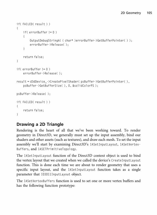
if( FAILED( result ) ){
if( errorBuffer != 0 ){
OutputDebugStringA( ( char* )errorBuffer->GetBufferPointer( ) );errorBuffer->Release( );
}
return false;}
if( errorBuffer != 0 )errorBuffer->Release( );
result = d3dDevice_->CreatePixelShader( psBuffer->GetBufferPointer( ),psBuffer->GetBufferSize( ), 0, &solidColorPS );
psBuffer->Release( );
if( FAILED( result ) ){
return false;}
Drawing a 2D Triangle
Rendering is the heart of all that we’ve been working toward. To rendergeometry in Direct3D, we generally must set up the input assembly, bind ourshaders and other assets (such as textures), and draw each mesh. To set the inputassembly we’ll start by examining Direct3D’s IASetInputLayout, IASetVertex-Buffers, and IASETPrimitiveTopology.
The IASetInputLayout function of the Direct3D context object is used to bindthe vertex layout that we created when we called the device’s CreateInputLayout
function. This is done each time we are about to render geometry that uses aspecific input layout, and the IASetInputLayout function takes as a singleparameter that ID3D11InputLayout object.
The IASetVertexBuffers function is used to set one or more vertex buffers andhas the following function prototype:
2D Geometry 105
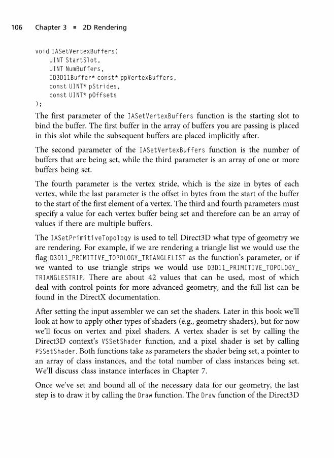
void IASetVertexBuffers(UINT StartSlot,UINT NumBuffers,ID3D11Buffer* const* ppVertexBuffers,const UINT* pStrides,const UINT* pOffsets
);
The first parameter of the IASetVertexBuffers function is the starting slot tobind the buffer. The first buffer in the array of buffers you are passing is placedin this slot while the subsequent buffers are placed implicitly after.
The second parameter of the IASetVertexBuffers function is the number ofbuffers that are being set, while the third parameter is an array of one or morebuffers being set.
The fourth parameter is the vertex stride, which is the size in bytes of eachvertex, while the last parameter is the offset in bytes from the start of the bufferto the start of the first element of a vertex. The third and fourth parameters mustspecify a value for each vertex buffer being set and therefore can be an array ofvalues if there are multiple buffers.
The IASetPrimitiveTopology is used to tell Direct3D what type of geometry weare rendering. For example, if we are rendering a triangle list we would use theflag D3D11_PRIMITIVE_TOPOLOGY_TRIANGLELIST as the function’s parameter, or ifwe wanted to use triangle strips we would use D3D11_PRIMITIVE_TOPOLOGY_
TRIANGLESTRIP. There are about 42 values that can be used, most of whichdeal with control points for more advanced geometry, and the full list can befound in the DirectX documentation.
After setting the input assembler we can set the shaders. Later in this book we’lllook at how to apply other types of shaders (e.g., geometry shaders), but for nowwe’ll focus on vertex and pixel shaders. A vertex shader is set by calling theDirect3D context’s VSSetShader function, and a pixel shader is set by callingPSSetShader. Both functions take as parameters the shader being set, a pointer toan array of class instances, and the total number of class instances being set.We’ll discuss class instance interfaces in Chapter 7.
Once we’ve set and bound all of the necessary data for our geometry, the laststep is to draw it by calling the Draw function. The Draw function of the Direct3D
106 Chapter 3 n 2D Rendering

context object takes as parameters the total number of vertices in the vertexarray and the start vertex location, which can act as an offset into the vertexbuffer where you wish to begin drawing.
An example of rendering geometry is as follows:
float clearColor[4] = { 0.0f, 0.0f, 0.25f, 1.0f };d3dContext_->ClearRenderTargetView( backBufferTarget, clearColor );
unsigned int stride = sizeof( VertexPos );unsigned int offset = 0;
d3dContext_->IASetInputLayout( inputLayout );d3dContext_->IASetVertexBuffers( 0, 1, &vertexBuffer_, &stride, &offset );d3dContext_->IASetPrimitiveTopology( D3D11_PRIMITIVE_TOPOLOGY_TRIANGLELIST );
d3dContext_->VSSetShader( solidColorVS, 0, 0 );d3dContext_->PSSetShader( solidColorPS, 0, 0 );d3dContext_->Draw( 3, 0 );
swapChain_->Present( 0, 0 );
Calling the swap chain’s Present function allows us to present the renderedimage to the screen. The Present function takes as parameters the sync intervaland the presentation flags. The sync interval can be 0 to present immediately, orit can be a value that states after which vertical blank we want to present (forexample, 3 means after the third vertical blank). The flags can be any of theDXGI_PRESENT values, where 0 means to present a frame from each buffer to theoutput, DXGI_PRESENT_DO_NOT_SEQUENCE to present a frame from each buffer tothe output while using the vertical blank synchronization, DXGI_PRESENT_TEST tonow present to the output (which can be useful for testing and error checking),or DXGI_PRESENT_RESTART to tell the driver to discard any outstanding request toPresent.
In Chapter 6 we’ll discuss how to draw indexed geometry when we move to thetopic of 3D rendering. Indexed geometry doesn’t serve much use in 2D scenes,but when we move to 3D it will be very important to cover it.
2D Geometry 107

2D Triangle Demo
In this section we’ll briefly cover the Triangle demo from the companion websitelocated in the Chapter3/Triangle folder. The purpose of this demo is to use whatwas covered thus far to render a single triangle to the screen. This demo buildsoff of the Blank Direct3D Window demo from Chapter 2.
Loading the Geometry
In this chapter we’ve discussed that in order to render geometry we need avertex buffer, an input layout describing the vertex layout used by the buffer, anda set of shaders. Since Direct3D 10, shaders are a base requirement for graphicsrendering in Direct3D, and in this demo we’ll be specifying vertex and pixelshaders that do nothing more than render a surface with a solid color. Later onin this chapter we’ll see how to extend this effect to map a texture image acrossthe surface.
The demo’s class, TriangleDemo from the TriangleDemo.h header file, adds tothe class members an ID3D11VertexShader called solidColorVS_, an ID3D11
PixelShader called solidColorPS, an ID3D11InputLayout called inputLayout_,and an ID3D11Buffer called vertexBuffer_. The TriangleDemo class from theTriangleDemo.h header file can be seen in Listing 3.1.
Listing 3.1 The TriangleDemo class header file.
#include"Dx11DemoBase.h"
class TriangleDemo : public Dx11DemoBase{
public:TriangleDemo( );virtual ~TriangleDemo( );
bool LoadContent( );void UnloadContent( );
void Update( float dt );void Render( );
108 Chapter 3 n 2D Rendering

private:ID3D11VertexShader* solidColorVS_;ID3D11PixelShader* solidColorPS_;
ID3D11InputLayout* inputLayout_;ID3D11Buffer* vertexBuffer_;
};
The vertex structure we will be using is a simple three-component floating-point structure from the XNA Math library called XMFLOAT3. As for theTriangleDemo class members, at the end of the application these objects willneed to be released by calling the Release method on each object. Releasing thememory used by these objects is performed in the UnloadContent function ofthe TriangleDemo class. Listing 3.2 shows the vertex structure and TriangleDemo
class constructor and destructor, while Listing 3.3 shows the UnloadContent
function.
Listing 3.2 TriangleDemo vertex structure, constructor, and destructor.
#include"TriangleDemo.h"#include<xnamath.h>
struct VertexPos{
XMFLOAT3 pos;};
TriangleDemo::TriangleDemo( ) : solidColorVS_( 0 ), solidColorPS_( 0 ),inputLayout_( 0 ), vertexBuffer_( 0 )
{
}
TriangleDemo::~TriangleDemo( ){
}
2D Triangle Demo 109

Listing 3.3 TriangleDemo’s UnloadContent.
void TriangleDemo::UnloadContent( ){
if( solidColorVS_ ) solidColorVS_->Release( );if( solidColorPS_ ) solidColorPS_->Release( );if( inputLayout_ ) inputLayout_->Release( );if( vertexBuffer_ ) vertexBuffer_->Release( );
solidColorVS_ = 0;solidColorPS_ = 0;inputLayout_ = 0;vertexBuffer_ = 0;
}
Next is the LoadContent function. This function begins by loading the vertexshader, which can be found in a file called SolidGreenColor.fx. The name of thisfile comes from the fact that the shaders within work together to shade a surfacewith a solid green color.
Once the vertex shader source is compiled and the shader created with a call toCreateVertexShader, we then create the vertex layout. Since the vertex layout isvalidated against the vertex shader signature, we need at least the vertex shaderloaded into memory.
After the vertex shader and input layout are created we next create the pixelshader. This code makes up half of the LoadContent function and can be seen inListing 3.4. The code for CompileD3DShader can also be seen in Listing 3.5 andwas separated out due to the fact that loading multiple shaders for differenteffects can cause us to write a lot of redundant code that we can avoid byabstracting the behavior in a member function of the base class DX11DemoBase
with the other high level Direct3D code.
Listing 3.4 LoadContent’s shader loading code.
bool TriangleDemo::LoadContent( ){
ID3DBlob* vsBuffer = 0;
bool compileResult = CompileD3DShader( "SolidGreenColor.fx",
110 Chapter 3 n 2D Rendering
"VS_Main", "vs_4_0", &vsBuffer );
if( compileResult == false ){
MessageBox( 0, "Error loading vertex shader!", "Compile Error", MB_OK );return false;
}
HRESULT d3dResult;
d3dResult = d3dDevice_->CreateVertexShader( vsBuffer->GetBufferPointer(),
vsBuffer->GetBufferSize( ), 0, &solidColorVS_ );
if( FAILED( d3dResult ) ){
if( vsBuffer )vsBuffer->Release( );
return false;}
D3D11_INPUT_ELEMENT_DESC solidColorLayout[] ={
{ "POSITION", 0, DXGI_FORMAT_R32G32B32_FLOAT,0, 0, D3D11_INPUT_PER_VERTEX_DATA, 0 }
};
unsigned int totalLayoutElements = ARRAYSIZE( solidColorLayout );
d3dResult = d3dDevice_->CreateInputLayout( solidColorLayout,totalLayoutElements, vsBuffer->GetBufferPointer( ),vsBuffer->GetBufferSize( ), &inputLayout_ );
vsBuffer->Release( );
if( FAILED( d3dResult ) ){
return false;}
2D Triangle Demo 111

ID3DBlob* psBuffer = 0;
compileResult = CompileD3DShader( "SolidGreenColor.fx","PS_Main", "ps_4_0", &psBuffer );
if( compileResult == false ){
MessageBox( 0, "Error loading pixel shader!", "Compile Error", MB_OK );return false;
}
d3dResult = d3dDevice_->CreatePixelShader( psBuffer->GetBufferPointer( ),psBuffer->GetBufferSize( ), 0, &solidColorPS_ );
psBuffer->Release( );
if( FAILED( d3dResult ) ){
return false;}
...}
Listing 3.5 The implementation of the CompileShader function.
bool Dx11DemoBase::CompileD3DShader( char* filePath, char* entry, char*shaderModel, ID3DBlob** buffer ){
DWORD shaderFlags = D3DCOMPILE_ENABLE_STRICTNESS;
#if defined( DEBUG ) || defined( _DEBUG )shaderFlags |= D3DCOMPILE_DEBUG;
#endif
ID3DBlob* errorBuffer = 0;HRESULT result;
result = D3DX11CompileFromFile( filePath, 0, 0, entry, shaderModel,shaderFlags, 0, 0, buffer, &errorBuffer, 0 );
112 Chapter 3 n 2D Rendering

if( FAILED( result ) ){
if( errorBuffer != 0 ){
OutputDebugStringA( ( char* )errorBuffer->GetBufferPointer( ) );errorBuffer->Release( );
}
return false;}
if( errorBuffer != 0 )errorBuffer->Release( );
return true;}
The second half of the LoadContent function creates the vertex buffer. This codebegins by defining a simple triangle that is half a unit in size along the X and Yaxes. It is also 0.5f along the Z axis to make it visible on screen, because if thecamera is too close or behind the surface, the surface won’t render.
The vertex list is stored in an array called vertices, and it is provided as a sub-resource data that is used during the call to CreateBuffer to create the actual vertexbuffer. The second half of the LoadContent function can be seen in Listing 3.6.
Listing 3.6 LoadContent’s geometry loading code.
bool TriangleDemo::LoadContent( ){
...
VertexPos vertices[] ={
XMFLOAT3( 0.5f, 0.5f, 0.5f ),XMFLOAT3( 0.5f, -0.5f, 0.5f ),XMFLOAT3( -0.5f, -0.5f, 0.5f )
};
D3D11_BUFFER_DESC vertexDesc;ZeroMemory( &vertexDesc, sizeof( vertexDesc ) );
2D Triangle Demo 113
vertexDesc.Usage = D3D11_USAGE_DEFAULT;vertexDesc.BindFlags = D3D11_BIND_VERTEX_BUFFER;vertexDesc.ByteWidth = sizeof( VertexPos ) * 3;
D3D11_SUBRESOURCE_DATA resourceData;ZeroMemory( &resourceData, sizeof( resourceData ) );resourceData.pSysMem = vertices;
d3dResult = d3dDevice_->CreateBuffer( &vertexDesc,&resourceData, &vertexBuffer_ );
if( FAILED( d3dResult ) ){
return false;}
return true;}
Rendering the Geometry
The last two pieces of code comprise the code to render the geometry and theshaders themselves. The code to render the geometry is found in the Triangle-
Demo’s Render function. The Render function is nearly the same as the examplerendering code we’ve examined earlier in this chapter when we discussed vertexbuffers. The function has a conditional statement to ensure that the Direct3Dcontext is valid.
Next we clear the rendering targets and set up the input assembler. Since thetriangle does not move, we don’t necessarily have to clear the rendering targets,but we’ll definitely need to do so later on in the book. The input assembler stageis set by binding the input layout object we’ve created, providing the vertexbuffer we are drawing out of, and setting the topology to triangle list.
The Render function from the TriangleDemo can be seen in Listing 3.7.
Listing 3.7 TriangleDemo’s rendering function.
void TriangleDemo::Render( ){
if( d3dContext_ == 0 )
114 Chapter 3 n 2D Rendering

return;
float clearColor[4] = { 0.0f, 0.0f, 0.25f, 1.0f };d3dContext_->ClearRenderTargetView( backBufferTarget_, clearColor );
unsigned int stride = sizeof( VertexPos );unsigned int offset = 0;
d3dContext_->IASetInputLayout( inputLayout_ );d3dContext_->IASetVertexBuffers( 0, 1, &vertexBuffer_, &stride, &offset );d3dContext_->IASetPrimitiveTopology( D3D11_PRIMITIVE_TOPOLOGY_
TRIANGLELIST );
d3dContext_->VSSetShader( solidColorVS_, 0, 0 );d3dContext_->PSSetShader( solidColorPS_, 0, 0 );d3dContext_->Draw( 3, 0 );
swapChain_->Present( 0, 0 );}
The last piece of code to view is the shaders. The vertex shader is as basic as theyget; it works by passing along the incoming vertex position to the output. Laterwe’ll have to manipulate this data to correctly draw our objects, but for thissimple demo it is enough to just pass along the values we’ve provided.
The pixel shader is also as basic as a pixel shader can be by returning a solidgreen color value for any pixel shaded using this shader. Colors from a pixelshader are specified using four floating-point values for the red, green, blue, andalpha color channels. In shaders we specify colors in the range of 0.0 to 1.0where 0.0 equals 0 and 1.0 equals 255 when using an unsigned char color bufferfor the rendering target (which we set up in the demo’s base class startupfunction).
The output of a vertex shader is the input to the pixel shader unless we have ageometry shader bound to the input assembler, which we do not. The output ofthe pixel shader is the color value that is written to the output buffer. This buffer iseventually displayed to the user when the swap chain’s Present function is called.
The vertex and pixel shaders from TriangleDemo can be seen in Listing 3.8. Ascreenshot of the demo can also be seen in Figure 3.13.
2D Triangle Demo 115

Listing 3.8 The Triangle demo’s shaders.
float4 VS_Main( float4 pos : POSITION ) : SV_POSITION{
return pos;}
float4 PS_Main( float4 pos : SV_POSITION ) : SV_TARGET{
return float4( 0.0f, 1.0f, 0.0f, 1.0f );}
Texture Mapping
As mentioned earlier in this chapter, a texture is data that is mapped to thesurface of our shapes and solids. Usually this data is color values that are used tomap an image onto the surface via a process called texture mapping. This datacould also be other pieces of information such as a normal map used for normalmapping, alpha values used to control transparency levels, and so forth.
Figure 3.13
Screenshot of the Triangle demo.
116 Chapter 3 n 2D Rendering
Textures, like other data your game needs, will usually be loaded at runtime.Since textures are an integral part of Direct3D, a few built-in functions areavailable to you for handling textures. For starters, the function D3DX11Create-
TextureFromFile is used to load in textures from a disk. This function supports avariety of popular graphics formats, such as BMP, PNG, and DDS. TheD3DX11CreateTextureFromFile function takes six parameters and has the follow-ing function prototype:
HRESULT D3DX11CreateTextureFromFile(ID3D11Device* pDevice,LPCTSTR pSrcFile,D3DX11_IMAGE_LOAD_INFO* pLoadInfo,ID3DX11ThreadPump* pPump,ID3D11Resource** ppTexture,HRESULT* pHResult
);
The first parameter to the D3DX11CreateTextureFromFile is the Direct3D device.This parameter must be a valid Direct3D device.
The second parameter of the D3DX11CreateTextureFromFile is the path and filename of the file being loaded.
The third parameter of the D3DX11CreateTextureFromFile is the image informa-tion structure. This is an optional parameter and allows the function to controlhow the texture image is loaded by allowing us to specify values for the CPUaccess flags, internal format, width and height, and so forth.
The fourth parameter of the D3DX11CreateTextureFromFile function is used forthe thread pump, which is used when loading the texture asynchronously viamulti threading.
The fifth parameter of the D3DX11CreateTextureFromFile function is the outaddress to the texture object being created by this function call. If this function issuccessful, this parameter will have a ready-to-go texture.
The last parameter is a pointer to the return value for the thread pump. If the threadpump parameter is not null, this parameter must be a valid location of memory.
In Direct3D we can use the Direct3D functions to load many different image fileformats, which are listed below:
Texture Mapping 117

n Windows Bitmap (BMP)
n Joint Photographic Expert Group—i.e., JPEG (JPG)
n Portable Network Graphics (PNG)
n Tagged Image Format (TIFF)
n Graphics Interchange Format (GIF)
n DirectDraw Surface (DDS)
n Windows Media Player (WMP)
Texture Interfaces
Texture interfaces are used to manage image data of a certain type. WithinDirect3D there are three main types of texture interfaces:
n ID3D11Texture1D—Handles a 1D or image strip type of texture.
n ID3D11Texture2D—2D image data. This is the most common type oftexture resource.
n ID3D11Texture3D—Image data used to represent volume textures (3Dtextures).
Each of these texture resources contains one or more subresources. The sub-resources represent the different MIP levels of the texture, which will be discussedin the next section. Most of the textures you use in your game will be of the 2Dvariety and will need to be converted to ID3D11Texture2D resources. Editors such asAdobe’s Photoshop are commonly used to create 2D textures, whereas oftentimes1D textures are arrays of data that are used as look-up tables within a shader.Usually the effects performed that often use 1D or 3D textures are advancedspecial effects and rendering techniques that go beyond simple texture mapping.
A 2D texture uses a single value for its texture coordinate. A texture coordinatecan be thought of as an array index into the texture image. Therefore, a 2Dtexture uses two values for the texture coordinates, also known as the TU andTV coordinates (or simply U and V), and 3D textures use three values (TU, TV,and TR). Cube maps, which we’ll briefly discuss in the section titled “TextureDetails,” also uses three texture coordinates since a cube map creates a muchmore simplistic volume than a 3D texture.
118 Chapter 3 n 2D Rendering

MIP Maps
Each pixel in a texture is known as a texel. A texel in a color map is a color value,usually between the values of 0 and 255 in common image formats. A 32-bitimage is made up of four 8-bit values, with one for the red, one for the green,one for the blue, and one for the alpha. In other words each component is asingle byte in size, and a 32-bit color is four bytes in size. On the other hand, anRGB image, where each component is stored in a single byte, is 24 bits in size.
Most image editors use color values in the range of 0 and 255 by default. Forexample, in Adobe Photoshop you can select colors from the color picker whencreating images, and each component of the color can be a value between 0 and255 (see Figure 3.14).
An image’s resolution describes its size along the width and height of theimage. An image with the resolution of 1024� 768 has a width of 1024 texelsby 768 texels. This is the same as saying an image of this size has 1,024 columnsand 768 rows in a table. That means for this resolution 1,024 times 768 equals786,432 texels in total. If each texel is 4 bytes each (32-bits), then the size of theimage is 786,432 times 4, which equals 3,145,728 bytes. This equates to 3072kilobytes, which is 3 megabytes of uncompressed data.
So what are MIP maps? MIP levels are decreasingly lower resolution versions ofthe same texture. MIP levels allow the system to swap in the proper texture
Figure 3.14
Selecting a 32-bit color in Adobe Photoshop.
Texture Mapping 119

resolution based on a surface’s distance. Objects further away need a lowertexture applied to them because they are not close enough to see all the detailanyway. An example can be seen in Figure 3.15 of various MIP levels.
Figure 3.16 shows an example of an object close to the viewer as well as far fromthe viewer. For objects that are far away from the viewer, the number of pixelsthat are shaded on the screen becomes less and less as the object moves away fromthe viewer. This means that, in order to preserve high quality, we’ll often need to
Figure 3.15
MIP Levels.
Figure 3.16
An object close and far from the viewer.
120 Chapter 3 n 2D Rendering

use high-resolution images for close objects. But if objects are far away, or if theycan move far away, high-resolution images do not need to be passed along therendering pipeline; instead, a lower-resolution version of the image can be used.
This is important because the less data we need to move, the faster ourperformance can potentially be. If there are many objects that are away fromthe camera, then using a texture resolution that is high enough to cause nonoticeable difference in appearance from the high-level version is one of the keysto improving performance. This process is known as mipmapping, and theD3DX11CreateTextureFromFile will create the full MIP level chain by default.Another benefit to using MIP maps comes from their ability to help reducealiasing artifacts.
This also brings forth two new terms called MIN and MAG. Minification occurs as thetextured surface moves away from the viewer. As the surface moves away, moretexels from the texture are combined to color a single screen pixel. This is becausemultiple textures occupy the same pixel for surfaces as they move away from theview. Magnification of the texture occurs when the textured surface gets closer tothe camera, causing more pixels to render the same texels. If each texel is beingapplied to a single pixel, then MIN and MAG do not occur, but in 3D games thereality is that these are pretty much always present for all textured surfaces.
Texture Details
Occasionally you’ll need to get certain information from a loaded texture such asits dimensions or pixel format. This information is available using the ID3D11-
Texture2D::GetDesc function. This function fills in a D3D11_TEXTURE2D_DESC
structure with all the details.
D3D11_TEXTURE2D_DESC is just one of the texture description structures availableand is specifically for 2D textures. Direct3D also has the structures D3D11_TEX
TURE1D_DESC and D3D11_TEXTURE3D_DESC available for 1D and 3D textures,respectively. The D3D11_TEXTURE2D_DESC structure will give you additionalinformation of a texture and can be seen as follows:
typedef struct D3D11_TEXTURE2D_DESC {UINT Width;UINT Height;UINT MipLevels;UINT ArraySize;
Texture Mapping 121
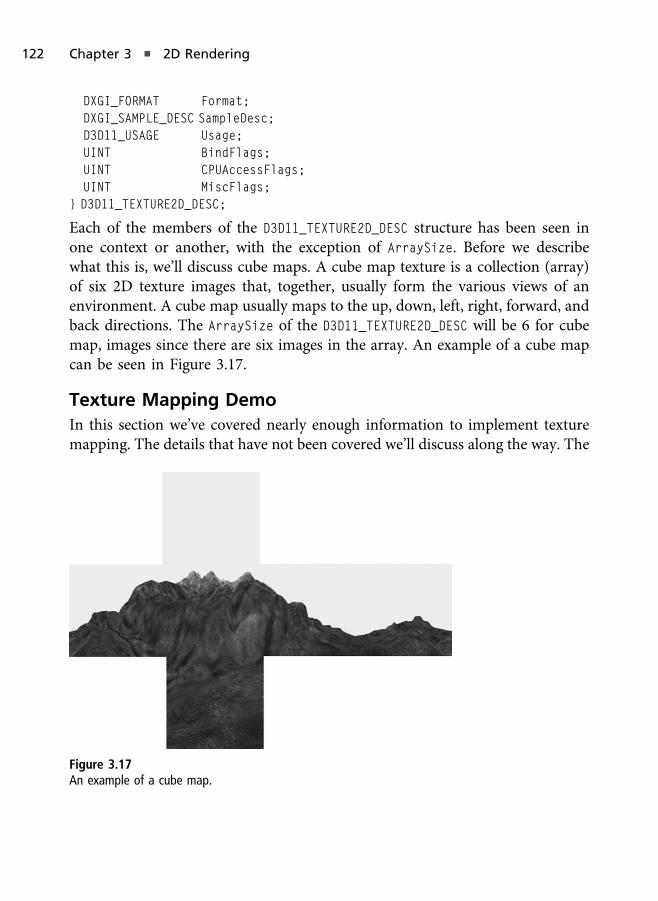
DXGI_FORMAT Format;DXGI_SAMPLE_DESC SampleDesc;D3D11_USAGE Usage;UINT BindFlags;UINT CPUAccessFlags;UINT MiscFlags;
} D3D11_TEXTURE2D_DESC;
Each of the members of the D3D11_TEXTURE2D_DESC structure has been seen inone context or another, with the exception of ArraySize. Before we describewhat this is, we’ll discuss cube maps. A cube map texture is a collection (array)of six 2D texture images that, together, usually form the various views of anenvironment. A cube map usually maps to the up, down, left, right, forward, andback directions. The ArraySize of the D3D11_TEXTURE2D_DESC will be 6 for cubemap, images since there are six images in the array. An example of a cube mapcan be seen in Figure 3.17.
Texture Mapping Demo
In this section we’ve covered nearly enough information to implement texturemapping. The details that have not been covered we’ll discuss along the way. The
Figure 3.17
An example of a cube map.
122 Chapter 3 n 2D Rendering

Texture Mapping demo can be found on the website in the Chapter 3/TextureMapping folder.
To start we’ll be building from the TriangleDemo code from earlier in thischapter. In the TextureDemo class we’ll add a shader resource view calledcolorMap_ (ID3D11ShaderResourceView) and a sampler state called color-
MapSampler_ (ID3D11SamplerState).
A shader resource view is an object shaders use to access resources. When weload the texture into memory we must create a shader resource view in order toaccess that data via a shader, and that is what we will be binding to the inputassembler. Shader resource views have other uses, such as providing generalpurpose data to DirectCompute for parallel computing, but in this chapter wewill focus only on textures. The ID3D11Texture2D is a buffer of data, while theshader resource view allows us to view that buffer in a shader.
A sampler state allows us to access sampling state information of a texture. We’lldiscuss this more when we look at how to create the object, but in general, notethat the sampler state allows us to set properties such as the texture filtering andaddressing—topics we’ll also discuss soon.
The TextureDemo class can be seen in Listing 3.9.
Listing 3.9 The TextureDemo class from the TextureDemo.h header file.
class TextureDemo : public Dx11DemoBase{
public:TextureDemo( );virtual ~TextureDemo( );
bool LoadContent( );void UnloadContent( );
void Update( float dt );void Render( );
private:ID3D11VertexShader* solidColorVS_;ID3D11PixelShader* solidColorPS_;
Texture Mapping 123
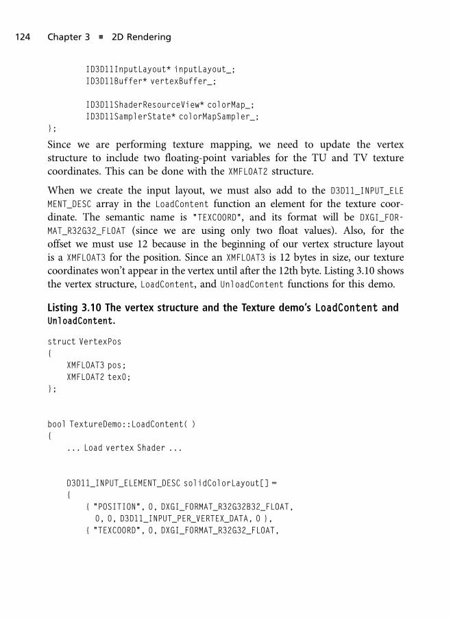
ID3D11InputLayout* inputLayout_;ID3D11Buffer* vertexBuffer_;
ID3D11ShaderResourceView* colorMap_;ID3D11SamplerState* colorMapSampler_;
};
Since we are performing texture mapping, we need to update the vertexstructure to include two floating-point variables for the TU and TV texturecoordinates. This can be done with the XMFLOAT2 structure.
When we create the input layout, we must also add to the D3D11_INPUT_ELE
MENT_DESC array in the LoadContent function an element for the texture coor-dinate. The semantic name is “TEXCOORD”, and its format will be DXGI_FOR-
MAT_R32G32_FLOAT (since we are using only two float values). Also, for theoffset we must use 12 because in the beginning of our vertex structure layoutis a XMFLOAT3 for the position. Since an XMFLOAT3 is 12 bytes in size, our texturecoordinates won’t appear in the vertex until after the 12th byte. Listing 3.10 showsthe vertex structure, LoadContent, and UnloadContent functions for this demo.
Listing 3.10 The vertex structure and the Texture demo’s LoadContent andUnloadContent.
struct VertexPos{
XMFLOAT3 pos;XMFLOAT2 tex0;
};
bool TextureDemo::LoadContent( ){
... Load vertex Shader ...
D3D11_INPUT_ELEMENT_DESC solidColorLayout[] ={
{ "POSITION", 0, DXGI_FORMAT_R32G32B32_FLOAT,0, 0, D3D11_INPUT_PER_VERTEX_DATA, 0 },
{ "TEXCOORD", 0, DXGI_FORMAT_R32G32_FLOAT,
124 Chapter 3 n 2D Rendering

0, 12, D3D11_INPUT_PER_VERTEX_DATA, 0 }};
unsigned int totalLayoutElements = ARRAYSIZE( solidColorLayout );
d3dResult = d3dDevice_->CreateInputLayout( solidColorLayout,totalLayoutElements, vsBuffer->GetBufferPointer( ),vsBuffer->GetBufferSize( ), &inputLayout_ );
... Load Pixel Shader ...
VertexPos vertices[] ={
{ XMFLOAT3( 1.0f, 1.0f, 1.0f ), XMFLOAT2( 1.0f, 1.0f ) },{ XMFLOAT3( 1.0f, -1.0f, 1.0f ), XMFLOAT2( 1.0f, 0.0f ) },{ XMFLOAT3( -1.0f, -1.0f, 1.0f ), XMFLOAT2( 0.0f, 0.0f ) },
{ XMFLOAT3( -1.0f, -1.0f, 1.0f ), XMFLOAT2( 0.0f, 0.0f ) },{ XMFLOAT3( -1.0f, 1.0f, 1.0f ), XMFLOAT2( 0.0f, 1.0f ) },{ XMFLOAT3( 1.0f, 1.0f, 1.0f ), XMFLOAT2( 1.0f, 1.0f ) },
};
... Create Vertex Buffer ...
d3dResult = D3DX11CreateShaderResourceViewFromFile( d3dDevice_,"decal.dds", 0, 0, &colorMap_, 0 );
if( FAILED( d3dResult ) ){
DXTRACE_MSG( "Failed to load the texture image!" );return false;
}
D3D11_SAMPLER_DESC colorMapDesc;ZeroMemory( &colorMapDesc, sizeof( colorMapDesc ) );colorMapDesc.AddressU = D3D11_TEXTURE_ADDRESS_WRAP;
Texture Mapping 125

colorMapDesc.AddressV = D3D11_TEXTURE_ADDRESS_WRAP;colorMapDesc.AddressW = D3D11_TEXTURE_ADDRESS_WRAP;colorMapDesc.ComparisonFunc = D3D11_COMPARISON_NEVER;colorMapDesc.Filter = D3D11_FILTER_MIN_MAG_MIP_LINEAR;colorMapDesc.MaxLOD = D3D11_FLOAT32_MAX;
d3dResult = d3dDevice_->CreateSamplerState( &colorMapDesc,&colorMapSampler_ );
if( FAILED( d3dResult ) ){
DXTRACE_MSG( "Failed to create color map sampler state!" );return false;
}
return true;}
void TextureDemo::UnloadContent( ){
if( colorMapSampler_ ) colorMapSampler_->Release( );if( colorMap_ ) colorMap_->Release( );if( solidColorVS_ ) solidColorVS_->Release( );if( solidColorPS_ ) solidColorPS_->Release( );if( inputLayout_ ) inputLayout_->Release( );if( vertexBuffer_ ) vertexBuffer_->Release( );
colorMapSampler_ = 0;colorMap_ = 0;solidColorVS_ = 0;solidColorPS_ = 0;inputLayout_ = 0;vertexBuffer_ = 0;
}
The UnloadContent function releases our new objects, and the remainder of theLoadContent function loads our texture image. To load a texture and create ashader resource view in one call, we can use the Direct3D utility functionD3DX11CreateShaderResourceViewFromFile. This function is useful when we
126 Chapter 3 n 2D Rendering

want to both load a texture and create a new shader resource view convenientlyat once. The D3DX11CreateShaderResourceViewFromFile function has the follow-ing prototype, whose parameters closely match the D3DX11CreateTextureFrom-
File function:
HRESULT D3DX11CreateShaderResourceViewFromFile(ID3D11Device* pDevice,LPCTSTR pSrcFile,D3DX11_IMAGE_LOAD_INFO* pLoadInfo,ID3DX11ThreadPump* pPump,ID3D11ShaderResourceView** ppShaderResourceView,HRESULT* pHResult
);
The last new section of code in the LoadContent function is the creation of thesampler state. To create a sampler state object, we call CreateSamplerState of theDirect3D device, which takes as parameters the sampler description and the outaddress to the sampler state object that will store the results. The samplerdescription has the following structure:
typedef struct D3D11_SAMPLER_DESC {D3D11_FILTER Filter;D3D11_TEXTURE_ADDRESS_MODE AddressU;D3D11_TEXTURE_ADDRESS_MODE AddressV;D3D11_TEXTURE_ADDRESS_MODE AddressW;FLOAT MipLODBias;UINT MaxAnisotropy;D3D11_COMPARISON_FUNC ComparisonFunc;FLOAT BorderColor[4];FLOAT MinLOD;FLOAT MaxLOD;
} D3D11_SAMPLER_DESC;
The first member of the D3D11_SAMPLER_DESC is a D3D11_FILTER member thatspecifies how the texture being sampled will be filtered. Texture filtering refersto the way values are read and combined from the source and made available tothe shader. Filtering can be used to improve quality but at the cost of moreexpensive texture sampling, since some filtering types can cause more than onevalue to be read and combined to produce a single color value that the shadersees. The various filtering types available in Direct3D 11 include the following:
Texture Mapping 127
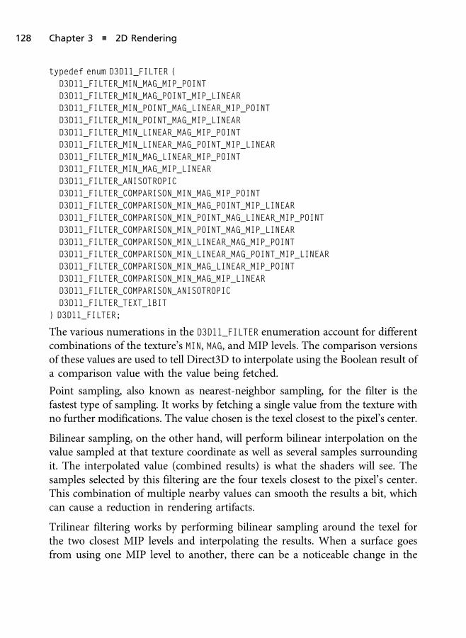
typedef enum D3D11_FILTER {D3D11_FILTER_MIN_MAG_MIP_POINTD3D11_FILTER_MIN_MAG_POINT_MIP_LINEARD3D11_FILTER_MIN_POINT_MAG_LINEAR_MIP_POINTD3D11_FILTER_MIN_POINT_MAG_MIP_LINEARD3D11_FILTER_MIN_LINEAR_MAG_MIP_POINTD3D11_FILTER_MIN_LINEAR_MAG_POINT_MIP_LINEARD3D11_FILTER_MIN_MAG_LINEAR_MIP_POINTD3D11_FILTER_MIN_MAG_MIP_LINEARD3D11_FILTER_ANISOTROPICD3D11_FILTER_COMPARISON_MIN_MAG_MIP_POINTD3D11_FILTER_COMPARISON_MIN_MAG_POINT_MIP_LINEARD3D11_FILTER_COMPARISON_MIN_POINT_MAG_LINEAR_MIP_POINTD3D11_FILTER_COMPARISON_MIN_POINT_MAG_MIP_LINEARD3D11_FILTER_COMPARISON_MIN_LINEAR_MAG_MIP_POINTD3D11_FILTER_COMPARISON_MIN_LINEAR_MAG_POINT_MIP_LINEARD3D11_FILTER_COMPARISON_MIN_MAG_LINEAR_MIP_POINTD3D11_FILTER_COMPARISON_MIN_MAG_MIP_LINEARD3D11_FILTER_COMPARISON_ANISOTROPICD3D11_FILTER_TEXT_1BIT
} D3D11_FILTER;
The various numerations in the D3D11_FILTER enumeration account for differentcombinations of the texture’s MIN, MAG, and MIP levels. The comparison versionsof these values are used to tell Direct3D to interpolate using the Boolean result ofa comparison value with the value being fetched.
Point sampling, also known as nearest-neighbor sampling, for the filter is thefastest type of sampling. It works by fetching a single value from the texture withno further modifications. The value chosen is the texel closest to the pixel’s center.
Bilinear sampling, on the other hand, will perform bilinear interpolation on thevalue sampled at that texture coordinate as well as several samples surroundingit. The interpolated value (combined results) is what the shaders will see. Thesamples selected by this filtering are the four texels closest to the pixel’s center.This combination of multiple nearby values can smooth the results a bit, whichcan cause a reduction in rendering artifacts.
Trilinear filtering works by performing bilinear sampling around the texel forthe two closest MIP levels and interpolating the results. When a surface goesfrom using one MIP level to another, there can be a noticeable change in the
128 Chapter 3 n 2D Rendering

appearance of that surface at that moment of change. Interpolating between theclosest MIP levels, after bilinearly filtering both levels, can greatly help to reducethese rendering artifacts.
Anisotropic filtering works by trilinearly sampling in a trapezoid area instead ofa square area. Bilinear and trilinear filtering work best when looking directly atthe surface because of the square area of sampling, but when viewing a surface atan angle, such as a floor or terrain in a 3D game, a noticeable amount ofblurriness and rendering artifacts can appear. Anisotropic filtering takes anglesinto consideration and samples using a different shaped area.
The next three members of the D3D11_SAMPLER_DESC structure are used fortexture address modes. Texture coordinates are specified in the range of 0.0 and1.0 for each dimension of the texture. The texture address mode tells Direct3Dhow to handle values outside of this range. The texture address mode for the U,V, and R can be one of the following values:
typedef enum D3D11_TEXTURE_ADDRESS_MODE {D3D11_TEXTURE_ADDRESS_WRAP,D3D11_TEXTURE_ADDRESS_MIRROR,D3D11_TEXTURE_ADDRESS_CLAMP,D3D11_TEXTURE_ADDRESS_BORDER,D3D11_TEXTURE_ADDRESS_MIRROR_ONCE,
} D3D11_TEXTURE_ADDRESS_MODE;
WRAP for the texture address will cause the texture to wrap around and repeat.For example, if you have a square shape and you want a texture to display twiceon it along the horizontal direction, you just need to specify 2.0 for the U texturecoordinates for the right most vertices, as seen in Figure 3.18. This can be usedto tile a texture along a single surface, which has the benefit of giving theappearance of more detail while using less data.
The MIRROR texture address mode will cause the texture to repeat but in a mirrordirection (see Figure 3.19), while CLAMP will simply clamp the values in the 0.0 to1.0 range. MIRROR_ONCE will mirror the texture one time, while MIRROR willcontinue it as specified. The BORDER address mode will set any pixels outside ofthe 0.0 to 1.0 range to a specified border color. The border color is specified byanother member of the D3D11_SAMPLER_DESC called BorderColor, which is anarray of four floating-point values.
Texture Mapping 129

The next member in the D3D11_SAMPLER_DESC structure is the level-of-detail(LOD) bias for the MIP. This value is an offset of the MIP level to use byDirect3D. For example, if Direct3D specifies that the MIP level to use is 2 andthe offset is set to 3, then the MIP ultimately used will be level 5.
Following the LOD bias is the max anisotropic value to use during anisotropicfiltering and the comparison function. The max anisotropic value can bebetween 1 and 16 and is not used for point or bilinear filtering. The COMPARISON
function is a value used for the comparison versions of the texture filtering flags.The comparison flags are specified in D3D11_COMPARISON_FUNC and are essentiallyflags stating the comparison should pass if one value is less than equal to, greaterthan, etc. another value.
Figure 3.18
Wrapping texture coordinates.
Figure 3.19
Mirror texture address mode.
130 Chapter 3 n 2D Rendering

The last two members of the D3D11_SAMPLER_DESC structure are used to clampthe min and max MIP levels that can be used. For example, if the max is set to 1,then level 0 will not be accessed (note that level 0 is the highest resolution).
The last piece of the puzzle besides the shaders is the rendering function. Torender our textured geometry, we must add the texture resource and set thesampler state. This is done by calling PSSetShaderResources and PSSetSamplers,which are used to set these items to the pixel shader. The PSSetShaderResources
has the following prototype and takes as parameters the start slot to begininserting resources, the number of resources being inserted, and an array ofresources to insert:
void PSSetShaderResources(UINT StartSlot,UINT NumViews,ID3D11ShaderResourceView* const* ppShaderResourceViews
);
The PSSetSamplers function also takes the start slot and number of samplersbeing set along with the array of samplers you are providing. With the additionof those two functions to our rendering code from the previous demo, we areready to see the effect in action. All that is missing is to modify the shaders toperform the actual effect. The rendering function used by the Texture Mappingdemo can be seen in Listing 3.11.
Listing 3.11 The Texture Mapping demo’s rendering function.
void TextureDemo::Render( ){
if( d3dContext_ == 0 )return;
float clearColor[4] = { 0.0f, 0.0f, 0.25f, 1.0f };d3dContext_->ClearRenderTargetView( backBufferTarget_, clearColor );
unsigned int stride = sizeof( VertexPos );unsigned int offset = 0;
d3dContext_->IASetInputLayout( inputLayout_ );d3dContext_->IASetVertexBuffers( 0, 1, &vertexBuffer_, &stride, &offset );
Texture Mapping 131
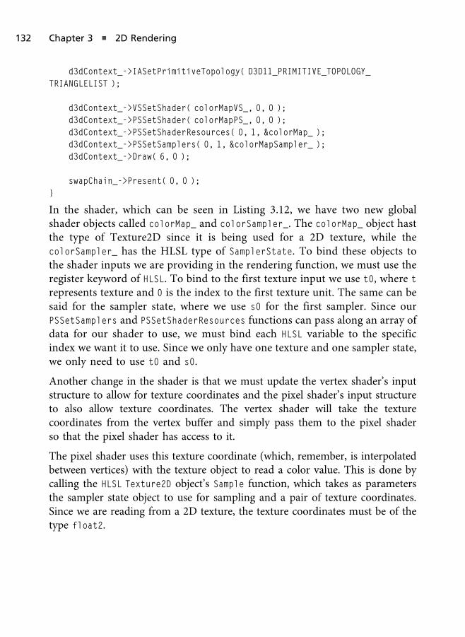
d3dContext_->IASetPrimitiveTopology( D3D11_PRIMITIVE_TOPOLOGY_TRIANGLELIST );
d3dContext_->VSSetShader( colorMapVS_, 0, 0 );d3dContext_->PSSetShader( colorMapPS_, 0, 0 );d3dContext_->PSSetShaderResources( 0, 1, &colorMap_ );d3dContext_->PSSetSamplers( 0, 1, &colorMapSampler_ );d3dContext_->Draw( 6, 0 );
swapChain_->Present( 0, 0 );}
In the shader, which can be seen in Listing 3.12, we have two new globalshader objects called colorMap_ and colorSampler_. The colorMap_ object hastthe type of Texture2D since it is being used for a 2D texture, while thecolorSampler_ has the HLSL type of SamplerState. To bind these objects tothe shader inputs we are providing in the rendering function, we must use theregister keyword of HLSL. To bind to the first texture input we use t0, where t
represents texture and 0 is the index to the first texture unit. The same can besaid for the sampler state, where we use s0 for the first sampler. Since ourPSSetSamplers and PSSetShaderResources functions can pass along an array ofdata for our shader to use, we must bind each HLSL variable to the specificindex we want it to use. Since we only have one texture and one sampler state,we only need to use t0 and s0.
Another change in the shader is that we must update the vertex shader’s inputstructure to allow for texture coordinates and the pixel shader’s input structureto also allow texture coordinates. The vertex shader will take the texturecoordinates from the vertex buffer and simply pass them to the pixel shaderso that the pixel shader has access to it.
The pixel shader uses this texture coordinate (which, remember, is interpolatedbetween vertices) with the texture object to read a color value. This is done bycalling the HLSL Texture2D object’s Sample function, which takes as parametersthe sampler state object to use for sampling and a pair of texture coordinates.Since we are reading from a 2D texture, the texture coordinates must be of thetype float2.
132 Chapter 3 n 2D Rendering
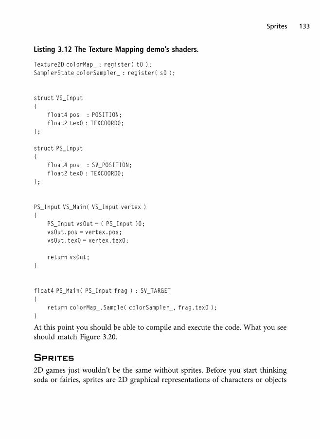
Listing 3.12 The Texture Mapping demo’s shaders.
Texture2D colorMap_ : register( t0 );SamplerState colorSampler_ : register( s0 );
struct VS_Input{
float4 pos : POSITION;float2 tex0 : TEXCOORD0;
};
struct PS_Input{
float4 pos : SV_POSITION;float2 tex0 : TEXCOORD0;
};
PS_Input VS_Main( VS_Input vertex ){
PS_Input vsOut = ( PS_Input )0;vsOut.pos = vertex.pos;vsOut.tex0 = vertex.tex0;
return vsOut;}
float4 PS_Main( PS_Input frag ) : SV_TARGET{
return colorMap_.Sample( colorSampler_, frag.tex0 );}
At this point you should be able to compile and execute the code. What you seeshould match Figure 3.20.
Sprites
2D games just wouldn’t be the same without sprites. Before you start thinkingsoda or fairies, sprites are 2D graphical representations of characters or objects
Sprites 133
within a game. Every tree, treasure chest, or dungeon creature you encounter ispresented onscreen using a sprite. Sprites are one of the most widely used andeasily understood aspects of 2D game programming. In 2D games, sprites areusually textured rectangles and squares that collectively create a virtual world.
Z-Ordering
In 2D games, some objects act as the background and some as the foreground,while others can be anything between the two, and these objects are known aslayers. A layer can be thought of as a piece of transparent paper. For example,the layer that acts as the background layer will only have background spritesrendered to it, while the action layer might have all of the characters, weapons,power-ups, etc. The order in which the layers are rendered will determine whichsprites are supposed to appear on top of what other sprites. In addition to havingdefined layers, there is also Z-ordering, which is the process in which objects aresorted before being drawn. Each sprite you create can be given a different Z-order value designating the depth at which it should be drawn. Sprites with alower Z-order value are drawn behind those sprites with a higher value, giving
Figure 3.20
Screenshot of the Texture Mapping demo.
134 Chapter 3 n 2D Rendering

the illusion of depth. For example, anything with a Z value of 1 is drawn on topof anything with a Z value of 0, and anything with a Z value of 2 is drawn on topof anything with a value of 0 or 1.
Using layers and/or Z-ordering allows us to define the rendering order in 2Dgames, but in 3D games we commonly use a concept known as depth testing forensuring surfaces appear to exist in the correct order, which we’ll discuss morein Chapter 6 once we enter 3D graphics.
Hardware depth testing uses a special rendering buffer known as a depth buffer,and it is used to determine if the previous surface’s depth at that pixel is fartherto the viewer than the current surface’s depth. In other words, if the previoussurface that was rendered at this location is further away from the camera thanthe current surface we are rendering, then the current surface is closer to thecamera and should be drawn on top of the previous data, else the previoussurface is in front of the current surface, and those pixels should not be updated.
Depth testing is one of the ways 3D games are able to correctly render objectswithout having to pre-sort polygons based on the camera’s view (we’ll examinethis in detail in Chapter 6). Since we are rendering using Direct3D, we coulddraw our 2D sprites in order of which sprites should appear in front of otherswithout needing to use a depth buffer. By clearing the screen completely anddrawing our sprites in layers, we could achieve proper results.
Sprite Image
The most important aspect of a sprite is its image. Traditionally, each spriteneeds an image to be associated with it both from a gameplay perspective and atechnical one. The image is what the sprite uses to convey its purpose to theplayer. For instance, your main character’s sprite in an RPG game may be theimage of a knight or even a spaceship in a space battle. You can choose anyimage you’d like, but your sprite can’t be displayed without an image.
This is because in the early days of 2D games sprite images were drawn directlyto the rendering destination and not to actual geometry. This is known astexture blitting. In Direct3D we can opt to draw 2D geometry and texture mapthat geometry rather than resorting to the old-fashioned methods of 2D gamegraphics. Texture blitting is essentially copying color values from the spriteimage to the rendering destination over a specific location of the destination.
Sprites 135
You can do this if you are creating a software rendering API for a 2D game, butusing Direct3D it is easier for us to use 2D textured rectangle geometry versustrying to create a software rendering API.
Earlier you learned how to load a texture from the disk; now you’ll learn howtextures can be used with sprites.
Getting Sprites to the Screen
When drawing sprites, the sprite object needs to know a few things about theenvironment in which it’s drawing. Not only does it need to know the positionof each and every sprite to avoid collisions on the same layer between solidobjects, but it needs to know the specifics about the area in which it’s drawing.This means the sprite object must be aware of the boundaries of the area wherethe sprites will be drawn. Normally, the size of this area is determined by theviewport associated with the Direct3D device.
The area in which the sprites are drawn is defined by its transformationmatrices. Matrices are discussed in detail in Chapter 6, but for now we’ll brieflycover the basics of the various matrices we use in graphics rendering. A matrixin Direct3D is a 4� 4 matrix. Visually it can be thought of as a table with 4 rowsand 4 columns for 16 elements in total. These four rows and columns allow us todo a lot in game graphics and simulations.
Usually in graphics programming we start off with three main types of trans-formation matrices. The first is used for projection transformation, the second isused for view transformations, and the third is used for world transformations.
When you transform vertices by a matrix, you are manipulating those verticesbased on the representation of that matrix. For example, a rotation matrix isused to rotate objects, a translation matrix is used to position objects, and ascaling matrix is used to scale matrices. But why do we need to do this?
Objects in 3D space are usually created using a 3D modeling application such asAutodesk’s 3D Studio Max. When models and objects are modeled, it is done inwhat is called model space. This means that the position of the vertices is specificto that model when it was modeled out in an editor. Usually models are createdaround the origin, just like we’ve been doing for our simple triangles and squaresin previous chapters (where the origin of (0, 0, 0) is the center of the shape).
136 Chapter 3 n 2D Rendering
In a game we can have one or more instances of this model, and these modelscan move and interact with the scene. But all of the model’s data is defined inmodel space, and as it moves throughout the world, the location of the verticesmust be updated to new positions. Also, when we position our models using alevel/map editor or as the models are interacting with the game (e.g., physics,artificial intelligence, etc.), we use matrices to position, rotate, and scale themodels. This allows us to have one model data loaded into memory for eachinstance and just render that model out multiple times for each instance thatexists. So if we have an asteroid field with 1,000 rocks, we will need only onerock model and 1,000 matrices to represent the position and orientation of eachasteroid. We could take it a step further and use Direct3D’s instancing feature toperform one draw call and supply in a buffer the per-instance transformationmatrices of all 1,000 rocks.
Simply put, a transformation matrix allows us to define the position andorientation of our objects virtually. A model created in an editor such as 3DStudio Max will be in model-space. When we apply the model’s geometry with atransformation matrix that represents positional, scaling, and orientation values,then we are transforming that model-space geometry into world-space. World-space is a context that represents the position of an object in relation to otherobjects in the world around them.
In games, especially 3D games, cameras play a big role. The orientation of thecamera also must be applied to the geometry in order to simulate the cameraeffect. The camera is represented by another matrix called the view matrix. Theview matrix allows us to take models in its current space and transform it intoview-space. When combined with the world matrix, we can create a single matrixthat does both of these transformations in one called the world-view matrix.
In addition to simulating a camera’s position and orientation, we also addprojection. A projection matrix is used to simulate orthogonal projection or tosimulate perspective projection. We could also apply other effects such as thezoom of a sniper scope by manipulating the projection matrix as well as othereffects.
We’ll discuss projection matrices in more detail in Chapter 6, but we’ll briefly goover them in a high-level view now. Orthographic projection is great for 2Delements because the visual depth of the objects being rendered is not applied to
Sprites 137

the final output. This means that if you have two boxes that are 10 units in sizebut 100 units away from each other along the Z axis, using orthogonal projectionwill cause them to appear to be right next to one other depth wise. Orthographicprojection is not only good for 2D games but also 2D interface elements of a 3Dgame, such as health bars, ammo counters, timers, text, etc.
Perspective projection on the other hand adds perspective to our renderedobjects. This means that objects get smaller on the screen as they move furtheraway from the camera or larger as they get closer to it. This can be seen in reallife if you look into the distance. Objects that are far away look small in the sensethat the area of your vision it occupies gets smaller with distance. If you arestanding in from of a building, the height of the building is a lot larger than ifyou were a mile away.
Combining the model, view, and projection matrices into one will create a newmatrix known as the model-view projection matrix. This matrix is used by thevertex shader to transform incoming geometry to the final position it will haveafter applying the model’s position and orientation, the camera’s view, and theprojection effects. Therefore, technically, we are using the vertex shader togenerate the model’s real position (known as the absolute position) from its localposition (known as its relative position). This is also how character animationsystems work in bone animation, where matrices are used to define poses ofanimation for groups of geometry defined by bones.
There are a few functions that are part of the XNA Math library that are used tobuild projection matrices, and each will be discussed in more detail in Chapter 6.For now we’ll look at XMMatrixOrthographicOffCenterLH as an example to getthings started off.
The function XMMatrixOrthographicOffCenterLH is used to create an ortho-graphic projection matrix using a left-handed coordinate system (Chapter 6).The return value for this function is a XMMATRIX structure where the resultingprojection matrix is placed. This function is used specifically to offset thecoordinates of the view to make the top-left corner have a custom value for the Xand Y axes (for example 0, 0). The function prototype for the XMMatrixOrthog-
raphicOffCenterLH can be seen as follows:
XMMATRIX XMMatrixOrthographicOffCenterLH(FLOAT ViewLeft,
138 Chapter 3 n 2D Rendering
FLOAT ViewRight,FLOAT ViewBottom,FLOAT ViewTop,FLOAT NearZ,FLOAT FarZ
)
The parameters to the XMMatrixOrthographicOffCenterLH define the projectionviewport, where the first parameter is the minimum X value, the second is themaximum X value, the third is the minimum Y value, and the fourth is themaximum Y value. The last two parameters are used to set the near and farclipping planes (Chapter 6). The near clipping plane will discard rendering ofanything in front of that value, and the far clipping plane will discard renderinganything after that value. This creates something known as a view volume. Theclipping planes play a much larger role in 3D graphics, where depth is moreprevalent.
The projection matrix lets the system know the size of the grid on which thesprites will be placed. For example, if the viewport is 640 pixels wide and480 pixels tall, then the projection matrix would restrict visible spritedrawing to that area. Sprites positioned outside of this area would not bevisible on the screen. This is handled by Direct3D in hardware.
The projection matrix only needs to be changed if the size of the viewportchanges or if we are performing some special camera effects that require us toswitch projection matrices. Do not worry if this is new information, becausewe’ll cover it in detail in Chapter 6. To get started with matrices, you don’t needto understand the internal details as long as you understand generally what theXNA Math functions are doing for you. Over time it will become moreimportant to understand the internals so that you can leverage that knowledgeto do anything you wish virtually.
Positioning and Scaling Sprites
Now that the sprites know the extent of their environment, positioning themwithin it is possible. The act of moving an object within a space is calledtranslation, where translation is another term for position. Sprites being twodimensional in nature can be translated in two directions, X and Y, although inDirect3D we technically could move in 3D space even for 2D objects.
Sprites 139

If you want to position a sprite in the center of a 640� 480 display area, youwould translate the sprite to an X, Y position of (320, 240). This, in effect, movesthe sprite 320 pixels horizontally and 240 pixels vertically when using anorthogonal projection that defines the upper left corner of the screen as (0, 0).When sprites are translated, they’re moved based on an internal point called thetranslation point. The translation point on a sprite is by default the location ofthe sprite’s model-space origin. When using sprites for characters within a game,it is common for the translation point to be moved to the top-left corner of thesprite.
When translating a sprite it is necessary to create another matrix called thetranslation matrix, which was briefly mentioned earlier in this chapter. Thetranslation matrix, once defined, is used by Direct3D to position the sprite (orany geometric object). The translation matrix can be created by using thefunction XMMatrixTranslation. The prototype to the XMMatrixTranslation canbe seen as follows:
XMMATRIX XMMatrixTranslation( FLOAT OffsetX, FLOAT OffsetY, FLOAT OffsetZ )
The return value for XMMatrixTranslation is the translation matrix, and theparameters it takes are the X, Y, and Z position values to move by. We also couldcreate a rotation and scaling matrix using other XNA Math functions that will beexamined in Chapter 6.
This was a bird’s-eye view of matrices, but it should be clear as to their purpose.We create a translation matrix to position objects, a rotation matrix to rotatethem, and scaling matrices to scale them (i.e., shrink or enlarge). The concat-enation of these three matrices together can be used to create the worldtransformation matrix. Concatenating the world matrix with the view andprojection matrices is used to create the model-view projection matrix, whichis used primarily by the vertex shader. The purpose of the vertex shader is tomanipulate incoming vertices, and matrix transformation is one of the tasksvertex shaders commonly perform. We won’t look at cameras and views untilChapters 6, 7, and 8, so we will largely ignore the view matrix until then.
The Game Sprite Demo
On the companion website in the Chapter3 folder is a demo called Game Sprites(Chapter3/GameSprite folder). The purpose of this demo is to create a game
140 Chapter 3 n 2D Rendering
sprite structure that can be used to represent a single instance of a sprite. We willwrite code that draws sprites to the screen, which can be used as the first stepstoward creating a 2D game.
So far we have a good idea of the values we’ll need for each sprite. To begin we’llcreate a simple game sprite class with the following members:
n Position
n Rotation
n Scale
n Sprite image
n Vertex buffer
Since this is a beginner’s book, we will create a vertex buffer and texture for eachunique sprite and render them for each sprite instance in the scene (i.e., morethan one sprite can use the same texture and vertex buffer). In a commercialgame where large amounts of draw calls and state changes are causing perform-ance issues, we’d opt to consider batching geometry and using texture atlases.These topics are move advanced and require a more intermediate level of skillwith Direct3D to properly implement.
No t e
A word of advice when considering premature optimizations is to avoid it. Only optimize when abottleneck has been identified, and address the problems of any bottlenecks until an acceptablelevel of performance is obtained. Optimizing for the sake of doing while developing code can leadto wasted effort on code that is not a performance burden or on code that is not a priority. In otherwords, don’t optimize some code when there are “bigger fish” (worse-performing code andbottlenecks) to fry.
The game sprite class is fairly simple, and its purpose is to use the position,rotation, and scale values to build the sprite’s world matrix when it is rendered.Once the world matrix is built, it is passed to the vertex shader using a constantbuffer. In order to avoid loading the same texture or creating the same vertex bufferover and over again, we’ll create them once in this demo and use them for eachsprite we are drawing. Since our focus is on rendering multiple sprites and on usingmatrices to position them, we won’t overly complicate things more than necessary.
The Game Sprite Demo 141

The game sprite class can be seen in Listing 3.13. The Game Sprite demo’s classcan also be seen in Listing 3.14. In the demo’s class we have an array of spriteresources that we will be drawing, a constant buffer for allowing us to pass datato the vertex shader, a view projection matrix (as a XMMATRIX), and a new blendstate object.
Listing 3.13 The GameSprite class from GameSprite.h.
#include<xnamath.h>
class GameSprite{
public:GameSprite( );virtual ~GameSprite( );
XMMATRIX GetWorldMatrix( );
void SetPosition( XMFLOAT2& position );void SetRotation( float rotation );void SetScale( XMFLOAT2& scale );
private:XMFLOAT2 position_;float rotation_;XMFLOAT2 scale_;
};
Listing 3.14 The Game Sprite demo class definition from GameSpriteDemo.h.
#include"Dx11DemoBase.h"#include"GameSprite.h"
class GameSpriteDemo : public Dx11DemoBase{
public:GameSpriteDemo( );
142 Chapter 3 n 2D Rendering

virtual ~GameSpriteDemo( );
bool LoadContent( );void UnloadContent( );
void Update( float dt );void Render( );
private:ID3D11VertexShader* solidColorVS_;ID3D11PixelShader* solidColorPS_;
ID3D11InputLayout* inputLayout_;ID3D11Buffer* vertexBuffer_;
ID3D11ShaderResourceView* colorMap_;ID3D11SamplerState* colorMapSampler_;ID3D11BlendState* alphaBlendState_;
GameSprite sprites_[2];ID3D11Buffer* mvpCB_;XMMATRIX vpMatrix_;
};
The blend state object has the type of ID3D11BlendState. We will use it in orderto render our textured sprites using alpha transparency. This means that wemust use 32-bit texture images with an alpha channel. The texture we are goingto display can be seen in in Figure 3.21 in Photoshop.
The constant buffer will be used to send the model-view projection matrix to thevertex shader so that the shader can transform the incoming geometry. Sincethere is no camera, and since the projection matrix does not change unless weresize the window, we can calculate the view-projection matrix once and use itwithin the rendering function when we calculate the full model-view projectionmatrix, which is why we have a XMMATRIX as a class member.
Creating and Rendering the Game Sprite
The GameSprite.cpp source file implements the GameSprite member functions,which in this demo we simply have set up as a way to store an individual sprite’s
The Game Sprite Demo 143
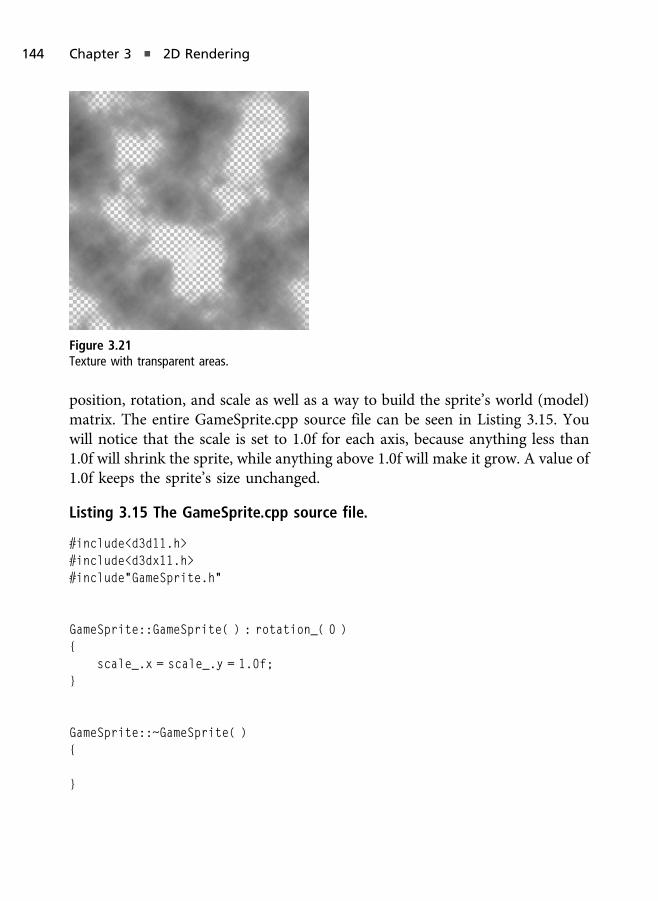
position, rotation, and scale as well as a way to build the sprite’s world (model)matrix. The entire GameSprite.cpp source file can be seen in Listing 3.15. Youwill notice that the scale is set to 1.0f for each axis, because anything less than1.0f will shrink the sprite, while anything above 1.0f will make it grow. A value of1.0f keeps the sprite’s size unchanged.
Listing 3.15 The GameSprite.cpp source file.
#include<d3d11.h>#include<d3dx11.h>#include"GameSprite.h"
GameSprite::GameSprite( ) : rotation_( 0 ){
scale_.x = scale_.y = 1.0f;}
GameSprite::~GameSprite( ){
}
Figure 3.21
Texture with transparent areas.
144 Chapter 3 n 2D Rendering
XMMATRIX GameSprite::GetWorldMatrix( ){
XMMATRIX translation = XMMatrixTranslation( position_.x, position_.y, 0.0f);
XMMATRIX rotationZ = XMMatrixRotationZ( rotation_ );XMMATRIX scale = XMMatrixScaling( scale_.x, scale_.y, 1.0f );
return translation * rotationZ * scale;}
void GameSprite::SetPosition( XMFLOAT2& position ){
position_ = position;}
void GameSprite::SetRotation( float rotation ){
rotation_ = rotation;}
void GameSprite::SetScale( XMFLOAT2& scale ){
scale_ = scale;}
To render a game sprite, we draw each game sprite by building the worldmatrix, applying that world matrix to the vertex shader’s constant buffer usingVSSetConstantBuffer, we bind the texture and shaders the sprite uses, and wethen render the geometry for that sprite resource. If we want to rendermultiple game sprites, we simply need to do this for each game sprite in thescene, which can be easily accomplished via a loop. The rendering functionfrom the GameSprite demo can be seen in Listing 3.16. Since the onlydifference between each sprite is its model-view projection matrix, the matrixis the only thing we need to set during each pass of the loop. Each time we callDraw we will draw out the sprite at the position of the last set model-viewprojection matrix.
The Game Sprite Demo 145

Listing 3.16 The rendering function from the Game Sprite demo.
void GameSpriteDemo::Render( ){
if( d3dContext_ == 0 )return;
float clearColor[4] = { 0.0f, 0.0f, 0.25f, 1.0f };d3dContext_->ClearRenderTargetView( backBufferTarget_, clearColor );
unsigned int stride = sizeof( VertexPos );unsigned int offset = 0;
d3dContext_->IASetInputLayout( inputLayout_ );d3dContext_->IASetVertexBuffers( 0, 1, &vertexBuffer_, &stride, &offset );d3dContext_->IASetPrimitiveTopology(D3D11_PRIMITIVE_TOPOLOGY_
TRIANGLELIST);
d3dContext_->VSSetShader( solidColorVS_, 0, 0 );d3dContext_->PSSetShader( solidColorPS_, 0, 0 );d3dContext_->PSSetShaderResources( 0, 1, &colorMap_ );d3dContext_->PSSetSamplers( 0, 1, &colorMapSampler_ );
for( int i = 0; i < 2; i++ ){
XMMATRIX world = sprites_[i].GetWorldMatrix( );XMMATRIX mvp = XMMatrixMultiply( world, vpMatrix_ );mvp = XMMatrixTranspose( mvp );
d3dContext_->UpdateSubresource( mvpCB_, 0, 0, &mvp, 0, 0 );d3dContext_->VSSetConstantBuffers( 0, 1, &mvpCB_ );
d3dContext_->Draw( 6, 0 );}
swapChain_->Present( 0, 0 );}
In the rendering code we set the constant buffer to the vertex shader by callingVSSetConstantBuffers. A constant buffer, like all DirectX 11 buffers, is of thetype ID3D11BUFFER and is created in the LoadContent function. As we’ve
146 Chapter 3 n 2D Rendering
mentioned earlier, a constant buffer is created by setting the buffer descriptor’sBindFlags member to D3D11_BIND_CONSTANT_BUFFER.
The game sprite and the various resources it uses are created in the LoadContent
function of the Game Sprite demo and are released in the UnloadContent
function, both of which can be seen in Listing 3.17 for the code relevant togame sprites. This demo builds directly off of the Texture Map demo fromearlier in this chapter, so we’ll leave out the upper portion of the LoadContent
function that is exactly the same from that demo.
Listing 3.17 The LoadContent and UnloadContent functions.
bool GameSpriteDemo::LoadContent( ){
// ... Previous code from the Texture Map demo...
ID3D11Resource* colorTex;colorMap_->GetResource( &colorTex );
D3D11_TEXTURE2D_DESC colorTexDesc;( ( ID3D11Texture2D* )colorTex )->GetDesc( &colorTexDesc );colorTex->Release( );
float halfWidth = ( float )colorTexDesc.Width / 2.0f;float halfHeight = ( float )colorTexDesc.Height / 2.0f;
VertexPos vertices[] ={
{ XMFLOAT3( halfWidth, halfHeight, 1.0f ), XMFLOAT2( 1.0f, 0.0f ) },{ XMFLOAT3( halfWidth, -halfHeight, 1.0f ), XMFLOAT2( 1.0f, 1.0f ) },{ XMFLOAT3( -halfWidth, -halfHeight, 1.0f ), XMFLOAT2( 0.0f, 1.0f ) },
{ XMFLOAT3( -halfWidth, -halfHeight, 1.0f ), XMFLOAT2( 0.0f, 1.0f ) },{ XMFLOAT3( -halfWidth, halfHeight, 1.0f ), XMFLOAT2( 0.0f, 0.0f ) },{ XMFLOAT3( halfWidth, halfHeight, 1.0f ), XMFLOAT2( 1.0f, 0.0f ) },
};
D3D11_BUFFER_DESC vertexDesc;ZeroMemory( &vertexDesc, sizeof( vertexDesc ) );
The Game Sprite Demo 147
vertexDesc.Usage = D3D11_USAGE_DEFAULT;vertexDesc.BindFlags = D3D11_BIND_VERTEX_BUFFER;vertexDesc.ByteWidth = sizeof( VertexPos ) * 6;
D3D11_SUBRESOURCE_DATA resourceData;ZeroMemory( &resourceData, sizeof( resourceData ) );resourceData.pSysMem = vertices;
d3dResult = d3dDevice_->CreateBuffer( &vertexDesc, &resourceData,&vertexBuffer_ );
if( FAILED( d3dResult ) ){
DXTRACE_MSG( "Failed to create vertex buffer!" );return false;
}
D3D11_BUFFER_DESC constDesc;ZeroMemory( &constDesc, sizeof( constDesc ) );constDesc.BindFlags = D3D11_BIND_CONSTANT_BUFFER;constDesc.ByteWidth = sizeof( XMMATRIX );constDesc.Usage = D3D11_USAGE_DEFAULT;
d3dResult = d3dDevice_->CreateBuffer( &constDesc, 0, &mvpCB_ );
if( FAILED( d3dResult ) ){
return false;}
XMFLOAT2 sprite1Pos( 100.0f, 300.0f );sprites_[0].SetPosition( sprite1Pos );
XMFLOAT2 sprite2Pos( 400.0f, 100.0f );sprites_[1].SetPosition( sprite2Pos );
XMMATRIX view = XMMatrixIdentity( );XMMATRIX projection = XMMatrixOrthographicOffCenterLH( 0.0f, 800.0f,
148 Chapter 3 n 2D Rendering

0.0f, 600.0f, 0.1f, 100.0f );
vpMatrix_ = XMMatrixMultiply( view, projection );
D3D11_BLEND_DESC blendDesc;ZeroMemory( &blendDesc, sizeof( blendDesc ) );blendDesc.RenderTarget[0].BlendEnable = TRUE;blendDesc.RenderTarget[0].BlendOp = D3D11_BLEND_OP_ADD;blendDesc.RenderTarget[0].SrcBlend = D3D11_BLEND_SRC_ALPHA;blendDesc.RenderTarget[0].DestBlend = D3D11_BLEND_ONE;blendDesc.RenderTarget[0].BlendOpAlpha = D3D11_BLEND_OP_ADD;blendDesc.RenderTarget[0].SrcBlendAlpha = D3D11_BLEND_ZERO;blendDesc.RenderTarget[0].DestBlendAlpha = D3D11_BLEND_ZERO;blendDesc.RenderTarget[0].RenderTargetWriteMask = 0x0F;
float blendFactor[4] = { 0.0f, 0.0f, 0.0f, 0.0f };
d3dDevice_->CreateBlendState( &blendDesc, &alphaBlendState_ );d3dContext_->OMSetBlendState( alphaBlendState_, blendFactor, 0xFFFFFFFF );
return true;}
void GameSpriteDemo::UnloadContent( ){
if( colorMapSampler_ ) colorMapSampler_->Release( );if( colorMap_ ) colorMap_->Release( );if( solidColorVS_ ) solidColorVS_->Release( );if( solidColorPS_ ) solidColorPS_->Release( );if( inputLayout_ ) inputLayout_->Release( );if( vertexBuffer_ ) vertexBuffer_->Release( );if( mvpCB_ ) mvpCB_->Release( );if( alphaBlendState_ ) alphaBlendState_->Release( );
colorMapSampler_ = 0;colorMap_ = 0;solidColorVS_ = 0;solidColorPS_ = 0;inputLayout_ = 0;
The Game Sprite Demo 149

vertexBuffer_ = 0;mvpCB_ = 0;alphaBlendState_ = 0;
}
The first thing we do in the LoadContent function is to obtain access to theloaded texture. We are doing this so that we can obtain the texture’s width andheight. This information is used during the creation of the vertex buffer so thatthe size of the image dictates how large the sprite is on screen.
After we create the vertex buffer using the information (width and height) we’veobtained from the texture image, we then create the constant buffer. Since we aresetting the constant buffer in each frame, we will hold off until the renderingfunction before filling in its contents.
The last portion of the LoadContent function sets the positions of our twosprites, creates our orthographic-based view-projection matrix, and creates ourblend state. We use the blend state to enable alpha transparency, which is atechnique for using the alpha channel of a color to dictate how visible it is. Analpha value of 1.0f is fully visible, 0.0 is invisible, and everything between is semitransparent.
To create the blend state we call the device’s CreateBlendState function, and toset the blend state we call the context’s OMSetBlendState function. CreateBlend-State takes a blend description and the out address of the blend state objectbeing created. OMSetBlendState takes the blend state that was created byCreateBlendState, a blend factor for each color channel, and a blend mask.The last two parameters are for more advanced blending, but for now we can setthem to default values.
The blend description is of the type D3D11_BLEND_DESC. Some of the members ofthe D3D11_BLEND_DESC are for advanced blending for topics such as multi-sampling, alpha-to-coverage, etc., but the minimum we need to set deals withthe render target’s source and destination blend. In the code listing you can seethat we enable alpha blending on the main rendering target and set up thesource of the blend to rely on the source color’s alpha value and destination torely on 1 – alpha (inverse of the alpha). This allows us to take the alpha value ofthe incoming source color and blend it with the destination based on 1 – alpha.In other words, anything with an alpha value of 0.0f for the source will cause the
150 Chapter 3 n 2D Rendering

destination’s color to appear, while anything with a 1 will cause the source’scolor to fully appear. Anything between 0.0f and 1.0f is a blend between thesource color (the color of the surface we are rendering) and the destination (thecontents of the rendered scene so far).
The last piece of the puzzle, the HLSL shader code, can be seen in Listing 3.18. Ascreenshot of the running demo can also be seen in Figure 3.22. In the HLSLcode we set up the constant buffer using the keyword cbuffer. The cbuffer
keyword allows us to create a single constant buffer in HLSL, but the contentswithin the constant buffer are accessed as if they were normally defined globalvariables, as you can see in the vertex shader where mvp_ is used directly. Theconstant buffer we are creating is binding to the input register of b0, whereastextures bind to t0 and higher, and samplers bind to s0 and higher.
The major change in this HLSL set of shaders is the fact that the vertex shader isusing the model-view projection matrix to transform the incoming vertex. Thisis done by simply multiplying the vertex by the matrix. The result is thetransformed vertex that is passed down the pipeline to the remaining stages. Thepixel shader is unchanged from the Texture Map demo.
Figure 3.22
Game Sprite demo screenshot.
The Game Sprite Demo 151

Listing 3.18 The Game Sprite demo’s HLSL shader code.
cbuffer cbChangesPerFrame : register( b0 ){
matrix mvp_;};
Texture2D colorMap_ : register( t0 );SamplerState colorSampler_ : register( s0 );
struct VS_Input{
float4 pos : POSITION;float2 tex0 : TEXCOORD0;
};
struct PS_Input{
float4 pos : SV_POSITION;float2 tex0 : TEXCOORD0;
};
PS_Input VS_Main( VS_Input vertex ){
PS_Input vsOut = ( PS_Input )0;vsOut.pos = mul( vertex.pos, mvp_ );vsOut.tex0 = vertex.tex0;
return vsOut;}
float4 PS_Main( PS_Input frag ) : SV_TARGET{
return colorMap_.Sample( colorSampler_, frag.tex0 );}
152 Chapter 3 n 2D Rendering

Summary
At this point you should have a basic understanding of how sprites and textureswork. Using the information presented in this chapter, it’s now possible to createa sprite-based demo that you can hopefully build on to create a simple 2D game.
Using Direct3D to draw 2D graphics really came down to using only the X andY positions of our geometry. We then were able to use the various vector andmatrix math code provided by Direct3D to manipulate these 2D objects as wesee fit. Technically there is no true 2D mode to Direct3D, and 2D is achievedeither using orthographic projection or by placing geometry with only X and Yaxes really close to each other in depth. In this chapter we’ve used orthographicprojection, so even if the depth was great between sprites, it wouldn’t affect howwe view them onscreen. If we used perspective projection, which is commonlyused for 3D rendering, then the depth distance plays a greater visual factor andallows us to switch into the realm of 3D.
What You Have Learned
In this chapter you learned the following:
n How textures are loaded.
n What a sprite is and how it’s used.
Chapter Questions
Answers to the following chapter review questions can be found in Appendix Aon this book’s companion website.
1. Define what a texture is.
2. Define what a sprite is. How are sprites different from textures?
3. List at least five different types of textures we’ve mentioned in this chapter.
4. How many bits are RGB images? How many bits are RGBA images?
5. Define a vertex.
6. Define a triangle.
Chapter Questions 153

7. What is the purpose of a vertex buffer? What is the Direct3D 11 objecttype of buffers?
8. List at least five attributes of a vertex.
9. Define an input layout and what it is used for in Direct3D.
10. What is a vertex shader, and what Direct3D function is used to set(apply) one?
11. What is a pixel shader, and what Direct3D function is used to set(apply) one?
12. List at least three input assembler functions we’ve used in the renderingfunctions of our demos.
13. What are MIP levels?
14. What are sampler states, and what is their purpose in Direct3D andHLSL?
15. What are blend states, and for what purpose did we use them in thischapter?
16. Define a matrix.
17. What are the various matrices that make up the model-view projectionmatrix, and what are their purposes?
18. What are texture address modes? Define each mode of theD3D11_TEXTURE_ADDRESS_MODE enumeration.
19. Enabling alpha transparency requires us to create and set what Direct3D11 object?
20. Why did we decide to use a XMFLOAT4X4 instead of XMMATRIX as the classmember in the Game Sprite demo?
On Your Own
Create your own sprite image in the image editor of your choice. Use that newlycreated image as the texture for the second sprite object.
154 Chapter 3 n 2D Rendering

Text and Font Rendering
Text doesn’t seem like it is going to be that useful when you’re writing games; itis a minor feature that doesn’t really affect the game. Or is it? Text is used formore than just the title screen or the scrolling credits you see when you’vecompleted a game. Text can be very useful when you have to give the playerinstructions, designate the goals of the game, or let the user know how manygold coins he has in his inventory. Text can be a valuable tool for user interfacesand feedback as well, such as ammo counters, the player’s health or shieldamount, energy meters, and so much more.
In this chapter:
n Why fonts and text are useful to game developers.
n How a font system works.
n How to create a simple font system from scratch.
n How to draw text to the screen.
Text in Games
From a programmer’s standpoint, text can be your best debugging tool. You canadd any number of real-time metrics that can be accessible at runtime, such asframe-rate count or text overlays for player names. An example of displaying theframe-rate count and in-game player names in a commercial game can be seenin Figures 4.1 and 4.2.
Chapter 4
155

In addition, many games implement what is known as a debug console in thegame itself, giving them a way to track and manipulate different areas of thegame. A debug console is a special screen where users can enter commandsusing an in-game command prompt to perform different actions. Think about itas a way to type commands into the game to alter values and states, such asdisplaying the FPS counter in Unreal Tournament, entering cheat codes,enabling debugging statistics, spawning objects, changing game properties, etc.An example game console can be seen in Figure 4.2.
Text was also used as a popular way to communicate between players in onlinematches on the PC. This was often performed by pressing a special chat keybutton (e.g., the “T” key on the keyboard), either for team chat or global chat,
Figure 4.1
An FPS counter in Epic Games’ Unreal Development Kit.
156 Chapter 4 n Text and Font Rendering
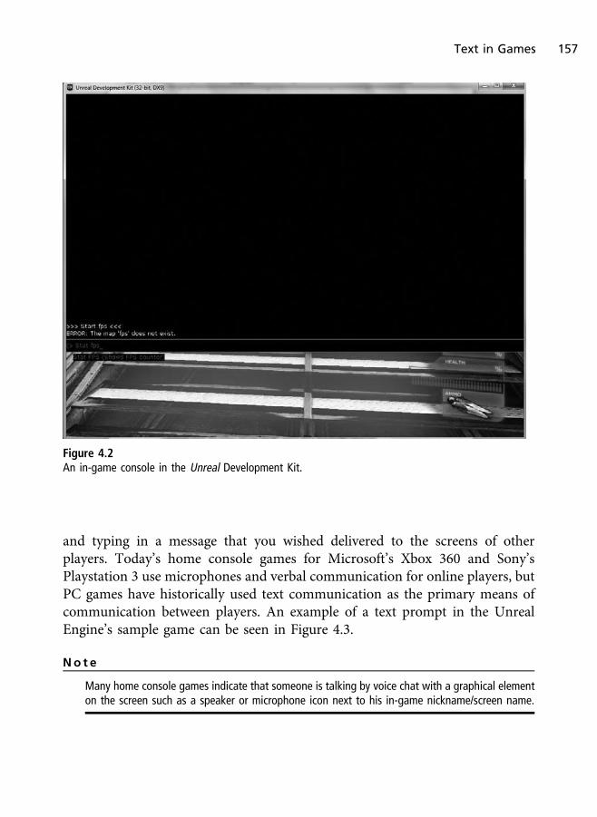
and typing in a message that you wished delivered to the screens of otherplayers. Today’s home console games for Microsoft’s Xbox 360 and Sony’sPlaystation 3 use microphones and verbal communication for online players, butPC games have historically used text communication as the primary means ofcommunication between players. An example of a text prompt in the UnrealEngine’s sample game can be seen in Figure 4.3.
No t e
Many home console games indicate that someone is talking by voice chat with a graphical elementon the screen such as a speaker or microphone icon next to his in-game nickname/screen name.
Figure 4.2
An in-game console in the Unreal Development Kit.
Text in Games 157

Adding Text
Over the years, game text has been implemented in multiple ways—texturedgeometry to the screen, vector drawing, and even just the use of standardmessage boxes. In modern game development, most game libraries support theconcept of text rendering, removing the burden of having to implement thisyourself. DirectX does support a method of text rendering prior to Direct3D 11,but Direct3D 11 does not offer the same built-in solutions we once enjoyed.Today we have to manually render our text using a font system based arounddrawing sprites dynamically, which is also the purpose of this chapter.
The following sections describe how font systems are commonly put together.
Figure 4.3
A text prompt in the Unreal Development Kit.
158 Chapter 4 n Text and Font Rendering

Textured Fonts
A font is a series of letters and symbols written in a certain graphical style. Forexample, the Times New Roman font in Microsoft Word looks different than theVerdana or Arial fonts. In other words, they have different graphical styles. Inboth 2D and 3D games, text is commonly drawn using textured geometry just aswe did with our sprites in Chapter 3. As we’ve described here, the term font isactually applied typography, since the letters and symbols that comprise the fontare of a specific artistic style.
Typography is defined as the study, design, and arrangement of type in media.Graphic designers for the web, print, television, etc. look at typography as a veryimportant element in their work. Typography can make or break a design, andthere are numerous books dedicated to the subject. Typography is important ingames, and its use should never be underestimated. Since our focus is onprogramming, we will not get caught up in the artistic and graphic design side ofthings, but be aware that typography is important for designers.
Textured fonts, also known as bitmapped fonts, are based on letters pre drawninto a texture image. The letters are arranged in a grid with a single letteroccupying each section of the grid. When it comes time to write out words, thewords are built dynamically by drawing the textured letters on the screen. Thisallows a single series of letters to be used to create any word or phrase yourequire. Because of the simplistic nature in which the font is used, text renderingcan be quite fast. Also, because the fonts are pre drawn on a texture, the look andfeel of the text can be changed by altering the applied texture.
Although very useful, textured fonts do have some downsides:
n Textured fonts don’t scale well. Because they are pieces of a texture, theycan only grow or shrink in size on the screen so much before theybecome ugly and unreadable due to rendering artifacts.
n The texture must support every possible letter or symbol you might use.This can make texture file sizes quite large.
n Localization. If your game supports multiple languages, you’ll need tex-tures with the correct character set (English, Japanese, Chinese, etc.) aswell as localized data translating between the languages.
Adding Text 159

n Because there are different amounts of spacing preceding and followingeach letter, textured fonts sometimes appear odd when writing certainwords because we often use the same amount of space for each characterthat is not based on that character’s actual width. For example, the letter“P” would be wider than the letter “l,” but the geometry they are mappedon (the grid space for any single character, as referred to in typographyas an em space) would be the same size, leaving more space betweensome letters than others.
n Creating a robust font system can be quite challenging for the first time.
Textured fonts allow for the buildup of words as they’re needed and aremanaged through some type of font system. Also, textured fonts can be createdto match the look and feel of the remainder of the user interface.
A Font System Explained
Occasionally there are instances when it makes sense to hard-code any text inthe game into preexisting graphics; a font system is used when the text that youneed to draw needs to be drawn dynamically. Examples include when asking forplayer input, displaying player chat (an example seen in the Unreal Develop-ment Kit in Figure 4.3), and so forth. If the text is not dynamic, there is littlereason to use a font system when a textured square would be sufficient. Ofcourse this might not always be the case.
Imagine that you’re playing an RPG and you need to talk to a resident in thevillage. In a hard-coded text system, what the character says is pre generated intoa texture and pulled up at the appropriate time. In other words, we’ll need entiretextures for every possible conversation exchange in the game. Depending on theamount of text in a single conversation, that could mean a very large number oftextures needing to be loaded.
A dynamic text system allows for the buildup of these strings by loading inonly a single texture containing all the letters in the font. This method couldsave load times and large amounts of memory used by textures. In a dynamicsystem, the text is generated by creating a list of squares side-by-side withtexture coordinates matching the region of the desired character.
160 Chapter 4 n Text and Font Rendering
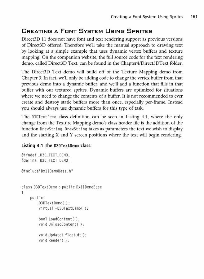
Creating a Font System Using Sprites
Direct3D 11 does not have font and text rendering support as previous versionsof Direct3D offered. Therefore we’ll take the manual approach to drawing textby looking at a simple example that uses dynamic vertex buffers and texturemapping. On the companion website, the full source code for the text renderingdemo, called Direct3D Text, can be found in the Chapter4/Direct3DText folder.
The Direct3D Text demo will build off of the Texture Mapping demo fromChapter 3. In fact, we’ll only be adding code to change the vertex buffer from thatprevious demo into a dynamic buffer, and we’ll add a function that fills in thatbuffer with our textured sprites. Dynamic buffers are optimized for situationswhere we need to change the contents of a buffer. It is not recommended to evercreate and destroy static buffers more than once, especially per-frame. Insteadyou should always use dynamic buffers for this type of task.
The D3DTextDemo class definition can be seen in Listing 4.1, where the onlychange from the Texture Mapping demo’s class header file is the addition of thefunction DrawString. DrawString takes as parameters the text we wish to displayand the starting X and Y screen positions where the text will begin rendering.
Listing 4.1 The D3DTextDemo class.
#ifndef _D3D_TEXT_DEMO_#define _D3D_TEXT_DEMO_
#include"Dx11DemoBase.h"
class D3DTextDemo : public Dx11DemoBase{
public:D3DTextDemo( );virtual ~D3DTextDemo( );
bool LoadContent( );void UnloadContent( );
void Update( float dt );void Render( );
Creating a Font System Using Sprites 161

private:bool DrawString( char* message, float startX, float startY );
private:ID3D11VertexShader* solidColorVS_;ID3D11PixelShader* solidColorPS_;
ID3D11InputLayout* inputLayout_;ID3D11Buffer* vertexBuffer_;
ID3D11ShaderResourceView* colorMap_;ID3D11SamplerState* colorMapSampler_;
};
#endif
The demo will work in a straightforward manner. To begin, we’ll load a textureimage of the letters A through Z. This texture image, shown in Figure 4.4, startswith the A character on the far left and ends with a space on the far right. The spacewill be used for invalid characters that do not match A through Z. To keep thisdemo simple we’ll only support uppercase letters and no symbols or numbers. Onceyou’ve gotten a handle on how this works, you can add support for those items asan additional exercise if you wish to expand upon this text rendering system.
The algorithm for texture rendering using the image seen in Figure 4.4 is simple.For each character in the string we’ll create a new sprite. The first sprite starts atthe starting X and Y location passed to the DrawString function parameters, andeach subsequent sprite (letter) will appear next to the one before it.
In the texture image each letter is 32� 32 pixels in size. Since there are 26 lettersand one space (empty letter), the image has a resolution of 864� 32, since27� 32 = 864. To keep the code easier to follow, all letters appear one after theother horizontally in the texture image. It also makes it easier to imagine howthe texture coordinates and vertex positions are calculated if we don’t have toworry about multiple rows and symbols.
To recap, when we create the text’s geometry we loop through each character ofthe string and create a new sprite right next to the last sprite. When we generatethe texture coordinates, we use the desired letter to dictate how we set them up.We’ll use the empty space at the end of the texture to handle invalid characters.
162 Chapter 4 n Text and Font Rendering
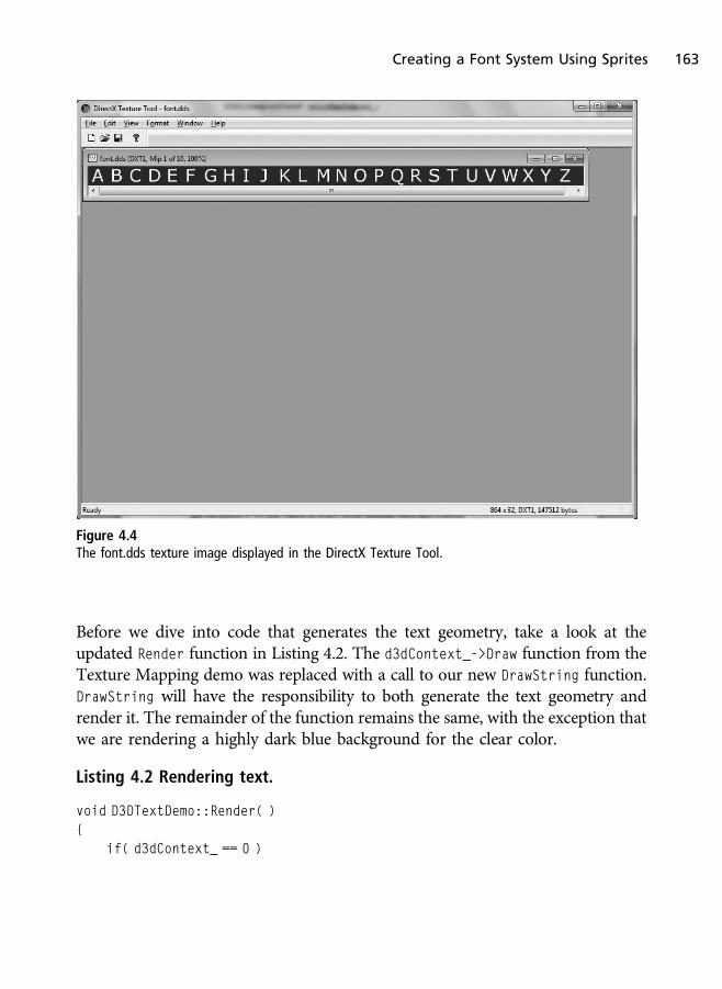
Before we dive into code that generates the text geometry, take a look at theupdated Render function in Listing 4.2. The d3dContext_->Draw function from theTexture Mapping demo was replaced with a call to our new DrawString function.DrawString will have the responsibility to both generate the text geometry andrender it. The remainder of the function remains the same, with the exception thatwe are rendering a highly dark blue background for the clear color.
Listing 4.2 Rendering text.
void D3DTextDemo::Render( ){
if( d3dContext_ == 0 )
Figure 4.4
The font.dds texture image displayed in the DirectX Texture Tool.
Creating a Font System Using Sprites 163

return;
float clearColor[4] = { 0.2f, 0.22f, 0.24f, 1.0f };d3dContext_->ClearRenderTargetView( backBufferTarget_, clearColor );
unsigned int stride = sizeof( VertexPos );unsigned int offset = 0;
d3dContext_->IASetInputLayout( inputLayout_ );d3dContext_->IASetVertexBuffers( 0, 1, &vertexBuffer_, &stride, &offset );d3dContext_->IASetPrimitiveTopology( D3D11_PRIMITIVE_TOPOLOGY_TRIANGLELIST );
d3dContext_->VSSetShader( solidColorVS_, 0, 0 );d3dContext_->PSSetShader( solidColorPS_, 0, 0 );d3dContext_->PSSetShaderResources( 0, 1, &colorMap_ );d3dContext_->PSSetSamplers( 0, 1, &colorMapSampler_ );
DrawString( "HELLO WORLD", -0.2f, 0.0f );
swapChain_->Present( 0, 0 );}
Also let’s take a look at the updated LoadContent function. The only changeshere are that we are loading a texture image called font.dds (instead of decal.ddsfrom the Texture Mapping demo), and we are creating a dynamic vertex buffer.To create a dynamic vertex buffer we perform the following steps:
1. Set the usage to D3D11_USAGE_DYNAMIC to allow our buffer to be updateddynamically by the CPU. In the previous demos this was set toD3D11_USAGE_DEFAULT for static buffers.
2. Set the CPU access flags to D3D11_CPU_ACCESS_WRITE. This must be donein order to grant the CPU write access for a resource within the GPU.Other access flags include read and read/write access, but we only needto write because the CPU does not need to read anything for this demo.
3. When creating the vertex buffer we can set null for the sub-resourceparameter (parameter 2). Since we are dynamically updating the vertexbuffer’s contents, we don’t need to set any data at this point.
164 Chapter 4 n Text and Font Rendering

With the dynamic buffer created, we are able to update its contents at any time.The changes we’ve made to the LoadContent function from the Texture Mappingdemo can be seen in Listing 4.3. Since the DrawString function will create thegeometry, we also deleted the code from the Texture Mapping demo thatdefined the two triangles and the code that copied that triangle data using thesub-resource Direct3D 11 object. Also notice in Listing 4.3 that we set up thevertex buffer to store up to 24 sprites (i.e., 24 letters). You can change the maxcharacter size if you desire.
Listing 4.3 Updating the LoadContent function.
bool D3DTextDemo::LoadContent( ){
. . .
d3dResult = D3DX11CreateShaderResourceViewFromFile( d3dDevice_,"font.dds", 0, 0, &colorMap_, 0 );
. . .
D3D11_BUFFER_DESC vertexDesc;ZeroMemory( &vertexDesc, sizeof( vertexDesc ) );vertexDesc.Usage = D3D11_USAGE_DYNAMIC;vertexDesc.CPUAccessFlags = D3D11_CPU_ACCESS_WRITE;vertexDesc.BindFlags = D3D11_BIND_VERTEX_BUFFER;
const int sizeOfSprite = sizeof( VertexPos ) * 6;const int maxLetters = 24;
vertexDesc.ByteWidth = sizeOfSprite * maxLetters;
d3dResult = d3dDevice_->CreateBuffer( &vertexDesc, 0, &vertexBuffer_ );
if( FAILED( d3dResult ) ){
DXTRACE_MSG( "Failed to create vertex buffer!" );return false;
}return true;
}
Creating a Font System Using Sprites 165

The final function in this demo is the DrawString function, which is also thefunction that performs all the work. This function is a bit long, so we’ll look at itin sections. In the first section we set up for values that we’ll need for thealgorithm. These values are broken down as follows:
n sizeOfSprite—The size of a single sprite in bytes. A sprite is two trian-gles made up of six vertices. This constant is here to aid in readability.
n maxLetters—We are coding this demo to be able to render up to24 characters at a time for simplicity, but you can always make thismore robust in the future once you have a handle on this topic.
n length—The length of the string we are attempting to render.
n charWidth—The width of an individual letter in screen coordinates.
n charHeight—The height of an individual letter in screen coordinates.
n texelWidth—The width of an individual letter in the texture image.
n verticesPerLetter—A constant storing the total vertices in each sprite(two triangles at six vertices).
For strings longer than 24 characters, we’ll clamp the total letters drawn to 24,else we’ll draw only the total number of letters in the string’s size. The firstsection of the DrawString function with the values we’ll be using for thealgorithm can be seen in Listing 4.4.
Listing 4.4 The DrawString function.
bool D3DTextDemo::DrawString( char* message, float startX, float startY ){
// Size in bytes for a single sprite.const int sizeOfSprite = sizeof( VertexPos ) * 6;
// Demo’s dynamic buffer set up for max of 24 letters.const int maxLetters = 24;
int length = strlen( message );
// Clamp for strings too long.if( length > maxLetters )
166 Chapter 4 n Text and Font Rendering

length = maxLetters;
// Char’s width on screen.float charWidth = 32.0f / 800.0f;
// Char’s height on screen.float charHeight = 32.0f / 640.0f;
// Char’s texel width.float texelWidth = 32.0f / 864.0f;
// verts per-triangle (3) * total triangles (2) = 6.const int verticesPerLetter = 6;
. . .
}
To update the contents of a dynamic buffer we need to call the Direct3D context’sMap function. The Map function takes as parameters the buffer we are mapping, thesub-resource index (set to 0 since there are not multiple sub-resources), themapping type, the map flags, and the mapped sub-resource that will hold theobtained data. The mapping type in this demo is D3D11_MAP_WRITE_DISCARD, whichtells Direct3D that the previous values in the buffer should be consideredundefined. For other map types, the map flags can be D3D11_MAP_FLAG_DO_NOT_
WAIT, but while using D3D11_MAP_WRITE_DISCARD we must use 0 for the map flagssince D3D11_MAP_FLAG_ DO_NOT_WAIT cannot be used with this mapping type.
Once Map has succeeded we will then have access to the buffer’s contents via theD3D11_MAPPED_SUBRESOURCE object we passed to the final parameter. To updatethe buffer we can simply copy whatever data we want to the D3D11_MAPPED_SU-
BRESOURCE’s pData member. The mapping section (second section) of the Draw-
String function can be seen in Listing 4.5. We also set up values that tell us theASCII values of the letters A and Z, which will be used in Listing 4.6 when weloop through and generate the string geometry.
Listing 4.5 Mapping of our vertex buffer.
bool D3DTextDemo::DrawString( char* message, float startX, float startY ){
. . .
Creating a Font System Using Sprites 167
D3D11_MAPPED_SUBRESOURCE mapResource;HRESULT d3dResult = d3dContext_->Map( vertexBuffer_, 0,
D3D11_MAP_WRITE_DISCARD, 0, &mapResource );
if( FAILED( d3dResult ) ){
DXTRACE_MSG( "Failed to map resource!" );return false;
}
// Point to our vertex buffer’s internal data.VertexPos *spritePtr = ( VertexPos* )mapResource.pData;
const int indexA = static_cast<char>( ’A’ );const int indexZ = static_cast<char>( ’Z’ );
. . .
}
In Listing 4.5 we obtain a pointer to the pData of the sub-resource so that we canloop through and set the geometry that will make up the string. To do this weuse a for-loop that iterates over the entire string. For each character, we set thestarting X and Y positions for the character. For the first character, the starting Xwill be the startX parameter of the DrawString function. As we loop through thecharacters, we essentially want to add the width of a character to this startingposition to get the next. By using the loop index we can multiply that by the sizeof a character’s width and add that to the starting position to get the currentletter’s position, which also allows us to not have to keep track of the previous Xposition, since this formula easily calculates the value we are looking for.
The starting X position is the left side of the sprite, and the ending X position isthe right side of the character, which is simply the start X position plus the sizeof an individual character.
Once we have set the vertex positions, we must do the same with the texturecoordinates. The texture coordinates are set in the same fashion, with one minordifference. Instead of using the loop index as the positions did, for texturecoordinates generation we use the letter itself. This can be easily done bycalculating the ASCII value of the letter, which is equivalent to casting it to aninteger. Since the first letter in our font.dds image is the letter A, if we subtract the
168 Chapter 4 n Text and Font Rendering

ASCII value of the current letter by the ASCII value of A, we can get a value of 0 ifthe current letter is A, 1 if it is B, and so forth. We can use this value, calledtexLookup in the DrawString function in the exact same manner as we used theloop index for the creation of the geometry positions. Just as the loop index i startsat 0 and increments upward, the texLookup variable starts at 0 for the first letter(A) and increments upward.
The texture coordinates usually range from 0.0 to 1.0. Our starting TU texturecoordinate will always be 0.0 for the first letter. In the DrawString function this iswritten mostly for consistency rather than necessity.
The texture coordinate formula matches the geometry formula exactly uponcloser inspection. For any invalid character, we set it to the last character in thefont.dds image, which is just an empty 32� 32 space at the end of the image. Weaccess this space by assuming that the current letter is 1 + Z because our fonttexture is set up to have the space appear after the Z graphic. The geometrygeneration of the DrawString function can be seen in Listing 4.6.
Listing 4.6 The loop in the DrawString function that creates the text.
bool D3DTextDemo::DrawString( char* message, float startX, float startY ){
. . .
for( int i = 0; i < length; ++i ){
float thisStartX = startX + ( charWidth * static_cast<float>( i ) );float thisEndX = thisStartX + charWidth;float thisEndY = startY + charHeight;
spritePtr[0].pos = XMFLOAT3( thisEndX, thisEndY, 1.0f );spritePtr[1].pos = XMFLOAT3( thisEndX, startY, 1.0f );spritePtr[2].pos = XMFLOAT3( thisStartX, startY, 1.0f );spritePtr[3].pos = XMFLOAT3( thisStartX, startY, 1.0f );spritePtr[4].pos = XMFLOAT3( thisStartX, thisEndY, 1.0f );spritePtr[5].pos = XMFLOAT3( thisEndX, thisEndY, 1.0f );
int texLookup = 0;int letter = static_cast<char>( message[i] );
Creating a Font System Using Sprites 169

if( letter < indexA || letter > indexZ ){
// Grab one index past Z, which is a blank space in the texture.texLookup = ( indexZ - indexA ) + 1;
}else{
// A = 0, B = 1, Z = 25, etc.texLookup = ( letter - indexA );
}
float tuStart = 0.0f + ( texelWidth * static_cast<float>( texLookup ) );float tuEnd = tuStart + texelWidth;
spritePtr[0].tex0 = XMFLOAT2( tuEnd, 0.0f );spritePtr[1].tex0 = XMFLOAT2( tuEnd, 1.0f );spritePtr[2].tex0 = XMFLOAT2( tuStart, 1.0f );spritePtr[3].tex0 = XMFLOAT2( tuStart, 1.0f );spritePtr[4].tex0 = XMFLOAT2( tuStart, 0.0f );spritePtr[5].tex0 = XMFLOAT2( tuEnd, 0.0f );
spritePtr += 6;}
. . .
}
The final step in the DrawString function is to unmap the vertex buffer.Unmapping must be done for any resource that was mapped by calling thedevice context’s Unmap function, which takes the buffer to unmap and the sub-resource index. With the vertex buffer updated with the necessary sprites todraw our text, we can call the Draw function to display our results. The Draw
function takes six times the length of the string for the vertex count because wehave six vertices for each sprite, and the length of the string represents the totalsprites we are drawing.
The final section of the DrawString function can be seen in Listing 4.7. Ascreenshot of the Direct3D Text demo can be seen in Figure 4.5.
170 Chapter 4 n Text and Font Rendering

Listing 4.7 The unmapping and drawing of our text.
bool D3DTextDemo::DrawString( char* message, float startX, float startY ){
. . .
d3dContext_->Unmap( vertexBuffer_, 0 );d3dContext_->Draw( 6 * length, 0 );
return true;}
Advanced Topics
There are many uses for text in video games. Some of these uses we’ve seen inthis chapter, and others you no doubt have seen in commercial games. Although
Figure 4.5
A screenshot of the Direct3D Text demo.
Advanced Topics 171

additional uses for text beyond what was covered in this chapter are beyond thescope of this book, at www.UltimateGameProgramming.com there are severaltutorials aimed at making more advanced use of text. If you’re interested, thesetutorials can be very useful when expanding your knowledge past the beginnerlevel. These tutorials include the following:
n Implementing text boxes (and other interface elements)
n In-game debug console
n Game screens
n In-game heads-up display (HUD)
In-Game Text Boxes
Text boxes sound like a simple concept, but their implementation takes somethought. A text box is not only its graphical element for where text is entered,but it also must display text on top of it. This would be simple, but we wouldalso have to add to it the ability for the text box to scroll the text for stringslarger than the text box’s area. We would need to consider a visual cue toindicate that the text box is ready to accept input, such as a flickering verticalline as seen in many text editors including Microsoft Word.
In-Game Console Window
An in-game console is another tricky-to-implement concept. For starters, theconsole window itself must store multiple lines of text for the past commandsand system text that were submitted. This can be done by displaying multiplelines of text on top of a full-screen textured background (or even no backgroundand display on top of the game screen itself). The text itself would most likely bestored in an array that stores the most recent text from oldest to newest.
The second part of the in-game console will be to provide a text box area for userinput, which was described in the previous section, “In-Game Text Boxes.” Thecombination of the string array display and the text box will allow us to create agood in-game console display.
But wait—there is one more thing. For any commands entered into the in-gameconsole, the game and/or game engine will have to process those commands andperform the actions they require. This can be done using what is known as
172 Chapter 4 n Text and Font Rendering

command scripting, a topic that is covered on www.UltimateGameProgramming.com. With a command script processor in place, the commands entered into thein-game console can be executed by the game.
Game Menus
A game’s menu system is far more complex than one would originally assumewithout having had any experience implementing them. Game menus are part ofa bigger concept known as game screens. There can be title screens, which arescreens that appear usually with developer and publisher names in text or videobefore the main menu appears, the main menu itself, a start game menu screen,a load game screen, an options screen, a high score screen, and many more. Incommercial games these screens can look and act in very complex ways, such asin the UDK seen in Figure 4.6.
Figure 4.6
Game menu screens in the Unreal Development Kit.
Advanced Topics 173

Other screens include the game screen (the screen responsible for playing theactual game), a pause menu screen, a multiplayer lobby screen, a control setupscreen, and many more. The next time you are playing a commercial game,notice how many different views and screens often appear. Usually there aremany.
No t e
Microsoft has released a game screen demo and its source for their XNA Game Studio Express,which is available at http://creators.xna.com.
Heads-Up Display
Heads-up display is a special type of screen displayed over the primary gameplayscreen, where the gameplay screen is the screen that displays the actualgameplay. The heads-up display, also known as the HUD, is the graphicalelement that appear on top of the action. This can include timers, ammoamounts, health indicators, enemy radar, and so forth. An example of a HUDcan be seen in Figure 4.7.
Summary
Knowing how to draw text to the screen can be a useful skill. You should be ableto easily implement font rendering using the Direct3D font object, or you canroll out your own text rendering system if desired. By manipulating where thetext is placed, the text can be used for real-time debugging information or as partof your user interface.
Taking the concepts you’ve learned up to this point, you can create your ownheads-up displays and game menus. This is more advanced and is definitely asubject to explore once you’ve mastered this book.
Chapter Questions
Answers to the following chapter review questions can be found in Appendix Aon this book’s companion website.
174 Chapter 4 n Text and Font Rendering
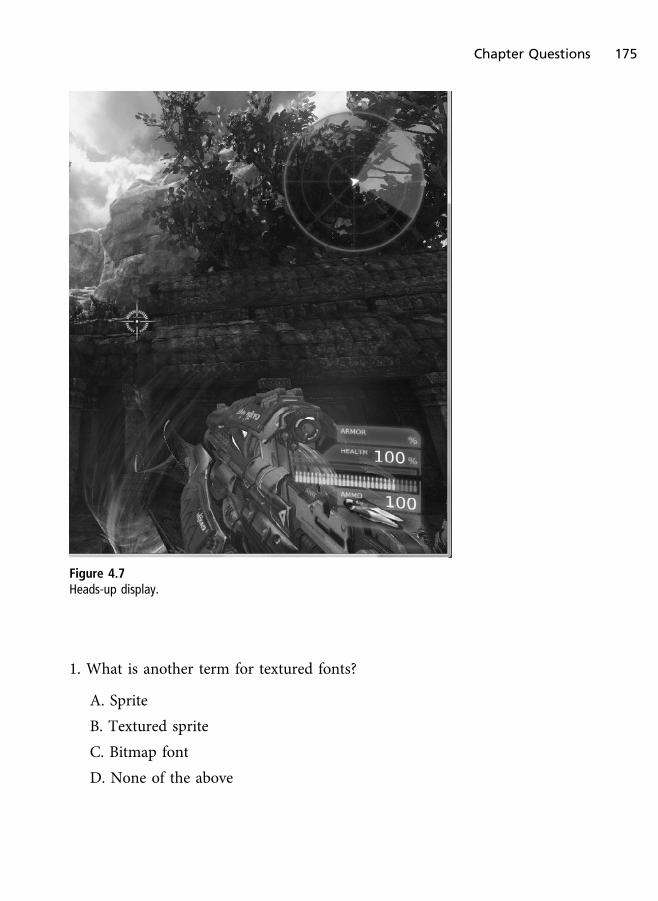
1. What is another term for textured fonts?
A. Sprite
B. Textured sprite
C. Bitmap font
D. None of the above
Figure 4.7
Heads-up display.
Chapter Questions 175
2. What is a font?
A. A style of characters.
B. A string of text.
C. A type of sprite.
D. None of the above.
3. True or False: Static text is best displayed using texture-mapped surfaces, notdynamically created sprites.
A. True
B. False
4. True or False: Write/discard map types must use the D3D11_MAP_FLAG_
DO_NOT_WAIT flag.
A. True
B. False
5. True or False: Direct3D has built-in text rendering.
A. True
B. False
On Your Own
1. Add alpha blending to the sprite-based font system.
2. Write a Render function that is capable of drawing multiple lines of text.
3. Add lowercase letters and numbers to the system.
176 Chapter 4 n Text and Font Rendering

Input Detection and
Response
Being able to interact with your virtual world is critical in any game—be itthrough the keyboard, mouse, or any number of other devices. In this chapterwe’ll explain the benefits of the various options for performing input detectionand how to use them.
In this chapter:
n Examine the various methods of input detection
n How DirectInput can make your life easier
n How to detect the input devices currently installed
n How to use keyboards, mice, and joysticks
n How to use Xbox 360 controllers
I Need Input
Every game needs the ability to interact with its user. Whether through akeyboard, mouse, dance pad, or other device, your game needs a way of gettingdirection from the person playing. The input device can be used to drive a cararound a track, move your character around in its world, or anything else thatyou can imagine.
Back in the days of DOS, game developers had very little choice but to pollhardware interrupts if they wanted to get keystrokes from the keyboard.
Chapter 5
177
Standard C functions of the time, such as getchar, were too slow to be useful forgames. Developers needed a better way; enter the Basic Input Output System(BIOS). The BIOS is the lowest level of software in a computer.
Stored normally in a flash ROM on the motherboard, the BIOS tells the systemhow to initialize and prepares the hardware for the operating system. The BIOSitself used to be directly accessible to programmers through assembly languagewhile under DOS. Since the BIOS knew everything that the hardware was doing,developers were able to ask it for certain information. One of the important bitsof the system that the BIOS was always watching was the keyboard. Every strokeof a key triggered a hardware interrupt, informing the system that a key hadbeen pressed. Since this happened almost instantaneously, a very quick andefficient method for getting keystrokes from the keyboard was available.
When Windows NT came along, the ability to read the keyboard directly from thehardware was eliminated. Windows became an absolute boundary betweenapplications and the hardware. Any information needed about the system had tobe gained from the operating system because applications were no longer alloweddirect access to the hardware. Windows had its own way of getting user input, andthat was through the message queue. An example message queue is as follows:
MSG msg = {0};
while (WM_QUIT != msg.message){
while( PeekMessage( &msg, NULL, 0U, 0U, PM_REMOVE ) == TRUE ){
TranslateMessage( &msg );DispatchMessage( &msg );
}}
The message queue collects events, such as mouse movement and keyboardinput, from the system. While this method is normally sufficient for Windowsapplications, it isn’t fast enough for games. Most developers at this point turnedto another Windows function, GetAsyncKeyState, to get the information theyneeded. GetAsyncKeyState’s function prototype is as follows, where its onlyparameter is a virtual key code:
SHORT WINAPI GetAsyncKeyState( int vKey );
178 Chapter 5 n Input Detection and Response

There are virtual key codes for every key on the keyboard; each is listed in theMSDN documentation. The GetAsyncKeyState function allowed for very quickchecking of the keys on the keyboard and even allowed for checking of multiplekeys and the state of the mouse buttons. This method of collecting user inputbecame common among game developers, but it had one major issue: It didn’tallow for input to be collected from other devices such as game pads andjoysticks. Game makers were stuck specifically supporting only certain devicesbecause each device had a different way of collecting and transmitting the inputdata to the system.
A standard way of getting fast input from the user was needed regardless of themethod or device used. The DirectX SDK offered DirectInput, which providedthe common layer needed to solve this problem.
Input Options
In this chapter we will look at obtaining input using various Win32 functionssuch as GetAsyncKeyState, DirectInput, and XInput. DirectInput allows yourgame to support a myriad of input devices without forcing you to know theexact details of each device. A small sample of the devices supported byDirectInput is shown here.
n Keyboards
n Mice
n Game pads
n Joysticks
n Steering wheels
DirectInput was last updated in DirectX 8 and is generally considered depre-cated. But Microsoft’s new API XInput only supports Xbox 360 controllers,which means that XInput does not support keyboards and mice devices. We canstill use DirectInput for keyboards and mice, but we could easily obtain thestates of these devices using various Win32 functions, which we’ll see through-out this chapter. For game pads and other next-generation controllers for theWindows OS it is recommended to use XInput.
I Need Input 179

Unfortunately this alienates non-Xbox 360 controllers, and if the need tosupport these devices exists, developers can still fall back to DirectInput sincethere are no Win32 functions for game controllers in the same way there are formice and keyboards. Because a need to support these devices still exists, andsince XInput does not support them, DirectInput is still a viable solution that isworth learning.
XInput is a relatively new API that first hit the scene in the later versions ofDirectX 9 and is available for detecting input from Xbox 360 game controllers.Game controllers include not only the standard Xbox 360 game pad but alsothese various devices:
n Arcade sticks
n Guitar Hero/Rock Band musical instruments
n Big button controllers
n Dance pads
n And more
In this chapter we will look at detecting keyboard and mouse input by obtainingthe device states using Win32 functions as well as through DirectInput. We’llalso look at how to detect input from Xbox 360 controllers through XInput.
Keyboard Input
The keyboard is one of two devices that we can assume a PC user has. Keyboardsand mice will likely always be highly important for PC games and the gamerswho support the platform.
In this section we will briefly discuss three options of obtaining input via thekeyboard in Windows. The first is to use the message queue, the second is toobtain the key states via Win32 functions such as GetAsyncKeyState, and thethird is to use DirectInput.
Win32 Keyboard Input
Win32 applications that we’ve been developing throughout this book havegenerally used the following windows procedure callback function for events:
180 Chapter 5 n Input Detection and Response

LRESULT CALLBACK WndProc( HWND hwnd, UINT message, WPARAM wParam, LPARAM lParam ){
PAINTSTRUCT paintStruct;HDC hDC;
switch( message ){
case WM_PAINT:hDC = BeginPaint( hwnd, &paintStruct );EndPaint( hwnd, &paintStruct );break;
case WM_DESTROY:PostQuitMessage( 0 );break;
default:return DefWindowProc( hwnd, message, wParam, lParam );
}
return 0;}
There are a ton of events that we could support, one of which is the WM_KEY DOWN
and WM_KEYUP events for keyboard actions. As an example, responding to theEscape key being pressed, and exiting the application as a result, would look likethis:
LRESULT CALLBACK WndProc(HWND hwnd, UINT message, WPARAM wParam, LPARAM lParam){
PAINTSTRUCT paintStruct;HDC hDC;
switch( message ){
case WM_PAINT:hDC = BeginPaint( hwnd, &paintStruct );EndPaint( hwnd, &paintStruct );break;
case WM_DESTROY:
Keyboard Input 181
PostQuitMessage( 0 );break;
case WM_KEYDOWN:switch(wParam){
case VK_ESCAPE:PostQuitMessage(0);break;
}break;
default:return DefWindowProc( hwnd, message, wParam, lParam );
}
return 0;}
The main problem with the message queue is that this method is far too slow.This method relies on the operating system sending the message to theapplication that a key was pressed. This is not instant, and there is often adelay between messages. For video games it is highly recommended that youavoid the message queue.
A better option is to obtain the state of the device the moment we want it (e.g.,every frame). This can easily be done in our demos by adding the following codeto the Update function:
void KeyboardDemo::Update( float dt ){
if( GetAsyncKeyState( VK_ESCAPE ) ){
PostQuitMessage( 0 );}
}
We can use GetAsyncKeyState to essentially tell us if a button is being pressed.The only parameter to this function is the virtual key code for the keyboardbutton we want to test for, and this provides an easy method to detect keyboard
182 Chapter 5 n Input Detection and Response
input. There is also the option to use the Win32 functions GetKeyState andGetKeyboardState, whose prototypes can be seen as follows:
SHORT WINAPI GetKeyState( int nVirtKey );
BOOL WINAPI GetKeyboardState( PBYTE lpKeyState );
DirectInput Keyboard Input
DirectInput is initialized in a very similar manner to other DirectX components,requiring the creation of both a DirectInput object as well as an input device.
The DirectInput object provides the interface needed to access DirectInputdevices. Through this interface, you are able to create an instance of a device,enumerate the devices on a system, or check the status of a particular device.
Once you have the DirectInput object created, you have to create the device. TheDirectInput device that you create will enable you to gain specific access to aninput device, be it a keyboard, joystick, or other gaming device.
After creating the device, you need to gain access to its input. This is done througha process called acquiring a device. When you acquire a device, you are providedwith access to initialize the device, get a list of its capabilities, or read its input.
It may seem like a lot of trouble to go through just to get a couple of keystrokesfrom a keyboard or game pad, but having direct access to your input device willmake your life simpler later on.
Now that you have access to the device, you’re able to read input from it eachframe. For example, if you are using a game pad as your input device, you cancheck to see if the user has pressed the direction buttons or if one of the predefinedaction buttons has been pressed. If so, you can then act on this information.
At this point, you should have a clear understanding of the process needed to getDirectInput up and running and getting data from an input device. We’ll nowwalk you through the code needed to do just that.
Creating the DirectInput Object
As mentioned, the first step to using DirectInput is the creation of theDirectInput object. The function DirectInput8Create is used to create theDirectInput object.
Keyboard Input 183

The DirectInput8Create function is defined as:
HRESULT WINAPI DirectInput8Create(HINSTANCE hinst,DWORD dwVersion,REFIID riidltf,LPVOID *ppvOut,LPUNKNOWN punkOuter );
Five parameters need to be passed to the DirectInput8Create function.
n hInst. An instance to the application that is creating the DirectInputobject.
n dwVersion. This is the version number of DirectInput that thisapplication requires. The standard value for this parameter isDIRECTINPUT_ VERSION.
n riidltf. The identifier of the required interface. Using the default valueof IID_IDirectInput8 is acceptable for this parameter.
n ppvOut. The pointer to the variable that will hold the createdDirectInput object.
n punkOuter. This parameter is normally set to null.
Below is a small snippet of code that will create a DirectInput object.
LPDIRECTINPUT8 directInputObject;
HRESULT hr = DirectInput8Create( hInst, DIRECTINPUT_VERSION,IID_IDirectInput8, ( void** )&directInputObject, 0 );
if FAILED( hr ){
return false;}
No t e
As a reminder, make sure to check the return value when creating DirectX objects. This will let youknow when an object creation has failed as well as help you track down bugs in your code. Afailure with a call to DirectInput8Create could possibly indicate a problem with the DirectXruntime, which can occur if the runtime was not installed properly.
184 Chapter 5 n Input Detection and Response
The preceding code first creates two variables: hr and directInputObject. Thefirst variable, hr, is defined as a standard HRESULT. This variable is used to checkthe return code of a function call. The second variable, directInputObject, isused to hold the soon-to-be-created DirectInput object.
The code then continues by making the call to DirectInput8Create. A quickcheck of the return code in the variable hr is done to make sure that the functionreturned successfully.
Creating the DirectInput Device
Now that you have a valid DirectInput object, you are free to create the device.The device is created using the function CreateDevice.
HRESULT CreateDevice( REFGUID rguid, LPDIRECTINPUTDEVICE *lplpDirectInputDevice, LPUNKNOWN pUnkOuter );
The CreateDevice function requires three parameters. The first parameter willbe either GUID_SysKeyboard or GUID_SysMouse for keyboards and mice devices,respectively, the second will be an out address for the DirectInput device objectbeing created, and a final parameter will deal with COM interfaces. Mostapplications will set the third parameter to null.
The following code assumes that you want to create a DirectInput device for aninstalled system keyboard.
LPDIRECTINPUTDEVICE8 keyboardDevice;
HRESULT hr = directInputObject ->CreateDevice( GUID_SysKeyboard,&keyboardDevice, 0 );
if FAILED(hr){
return false;}
The preceding code first creates the object keyboardDevice. This type LPDIR
ECTINPUTDEVICE8 is used to hold the created DirectInput device.
The call to CreateDevice, which is a method available to you through theDirectInput object, is made by passing in the value GUID_SysKeyboard as the firstparameter. This tells CreateDevice that you want a device object created based
Keyboard Input 185

on the system keyboard. The second parameter is the device object that will becreated as a result of this function call, and the third parameter dealing withCOM interfaces is null.
After this function call is complete, the keyboard device will hold a validDirectInput device. Be sure that the return code for this function is checked toconfirm that the device is valid.
Setting the Data Format
After a valid DirectInput device has been created, you need to set up the dataformat that DirectInput will use to read input from the device. The SetData
Format function defined next requires a DIDATAFORMAT structure as its onlyparameter.
HRESULT SetDataFormat( LPCDIDATAFORMAT lpdf )
The DIDATAFORMAT structure describes various elements of the device forDirectInput. The DIDATAFORMAT structure is defined here:
typedef struct DIDATAFORMAT{
DWORD dwSize;DWORD dwObjSize;DWORD dwFlags;DWORD dwDataSize;DWORD dwNumObjs;LPDIOBJECTDATAFORMAT rgodf;
} DIDATAFORMAT, *LPDIDATAFORMAT;
It is necessary to create and use your own DIDATAFORMAT structure if the inputdevice you want to use is not a standard device. There are a number ofpredefined DIDATAFORMAT structures for common input devices.
n c_dfDIKeyboard
n c_dfDIMouse
n c_dfDIMouse2
n c_dfDIJoystick
n c_dfDIJoystick2
186 Chapter 5 n Input Detection and Response

If the input device you want to use is not included as one of the predefined types,you will need to specifically create a DIDATAFORMAT object. Most of the commoninput devices will not require this since it is rare to need the ability to create acustom data format.
The following code sample calls the SetDataFormat function using the prede-fined DIDATAFORMAT structure for a keyboard device.
HRESULT hr = keyboardDevice ->SetDataFormat( &c_dfDIKeyboard );
if FAILED(hr){
return false;}
Setting the Cooperation Level
The cooperative level is needed to tell the system how the input device that youare creating will work with the system. Input devices can be set to use eitherexclusive or non-exclusive access. Exclusive access means that only yourapplication has the ability to use a particular device and does not need toshare it with other applications that Windows may be running. This is mostuseful when your game is a full-screen application. When a device, such as themouse or keyboard, is being used exclusively by a game, any attempt for anotherapplication to use this device will fail.
If your game doesn’t mind sharing the device, then this is called non-exclusiveaccess. When a game creates the device with non-exclusive access, otherapplications running will be able to use that same device. This is most usefulwhen your game is running in windowed mode on the Windows desktop. Usingthe mouse as a non-exclusive input device will not restrict the use of the mousein other application windows.
Each game that uses a DirectInput device must set the cooperative level for itsuse. This is done through the function SetCooperativeLevel, defined here:
HRESULT SetCooperativeLevel( HWND hwnd, DWORD dwFlags );
The SetCooperativeLevel function requires only two parameters, where the firstparameter is a handle to the window that is requesting access to the device and
Keyboard Input 187

the second is a series of flags that describe the type of access you are requesting.The available flags are these:
n DISCL_BACKGROUND. The application is requiring background access to thedevice, which means that the input device can be used even when thegame window is not the window currently active.
n DISCL_EXCLUSIVE. The game is requesting complete and exclusive controlover the device.
n DISCL_FOREGROUND. The game only requires input when the window is thecurrent active window on the desktop. If the game window loses focus,input to this window is halted.
n DISCL_NONEXCLUSIVE. Exclusive access is not needed, and the device canbe shared with other applications.
n DISCL_NOWINKEY. This tells DirectInput to disable the Windows key onthe keyboard.
No t e
Each application must specify whether it needs foreground or background access to the device bysetting either the DISCL_BACKGROUND or DISCL_FOREGROUND flag. The application is alsorequired to set either the DISCL_EXCLUSIVE or DISCL_NONEXCLUSIVE flag. The DISCL_NOWINKEY flag is completely optional.
The following code sample sets the device to use non-exclusive access and onlybe active when the application window has focus.
hr = keyboardDevice->SetCooperativeLevel( hwnd,DISCL_FOREGROUND | DISCL_NONEXCLUSIVE );
if FAILED(hr){
return false;}
You’ll notice that the SetCooperativeLevel function is a method callablethrough the DirectInput device interface. The keyboardDevice object aboverepresents the current DirectInput device created by the call to CreateDevice.
188 Chapter 5 n Input Detection and Response

The parameters being passed in the example SetCooperativeLevel functionabove consist of hwnd, which represents the handle to the window requestingaccess to the input device, and the flags DISCL_FOREGROUND and DISCL_NONEX
CLUSIVE, telling DirectInput the access you are requesting for the device.
Acquiring the Device
The final step required before you are able to read input from a particular deviceis called “acquiring the device.” When you acquire access to an input device, youare telling the system that you are ready to use and read from this device. Thefunction Acquire, another method of the DirectInput device, performs thisaction. The Acquire function, defined next, takes no parameters and returnsonly whether or not it was successful.
HRESULT Acquire( VOID );
The following small code example shows how the Acquire function is called:
HRESULT hr = keyboardDevice->Acquire( );
If( FAILED( hr ) ){
return false;}
You’ll notice again that the return code for this function is checked to make sureit was completed successfully. Since this is the last step needed before readinginput from a device, it’s best to check the return code to make sure the device isready and available.
Getting Input
Now that we’ve completed the required steps to initialize an input devicethrough DirectInput, it’s time to actually use it. All devices use the functionGetDeviceState when reading input. Whether the input device is a keyboard,mouse, or game pad, the GetDeviceState function is used.
HRESULT GetDeviceState( DWORD cbData, LPVOID lpvData );
The first parameter required is a DWORD value that holds the size of the buffer beingpassed as the second parameter. The second parameter is a pointer to the bufferthat will hold the data read from the device. As a reminder, the format of the datafrom the input device was defined earlier using the SetDataFormat function.
Keyboard Input 189
The next few sections will show how to enumerate the input devices available toyour application through DirectInput.
Enumerating Input Devices
Most games available for the PC allow for use of input devices other than akeyboard or a mouse, such as a game pad or joystick. Many computers do nothave these non-standard devices by default, so DirectInput cannot just assumetheir presence. Also, since Windows allows for multiple game pads or joysticksto be installed simultaneously, DirectInput needs a way of determining howmany and what type these devices are. The method DirectInput uses to get theneeded information on the input devices is called enumeration.
Just as Direct3D can enumerate through the video adapters installed in a systemand get the capabilities of each, DirectInput can do the same for input devices.
Using functions available through the DirectInput object, DirectInput is able toretrieve the number of input devices available in a system as well as each one’stype and functionality. For instance, if your game requires the use of a game padwith an analog control stick, you can enumerate the installed devices and see ifany of them meet your criteria.
The process of enumerating the installed devices on a system requires firstgathering a list of the devices that meet your input need, and secondly gatheringthe specific capabilities of these devices.
DirectInput uses the function EnumDevices to gather the list of installed inputdevices. Since there are different types of devices possibly installed on a machine,and you probably wouldn’t be interested in getting a list of them all, EnumDevicesallows you to specify the type of devices you are searching for. For instance, ifyou’re not interested in the mouse and keyboard devices and are searchingspecifically for joystick devices, EnumDevices provides a way of eliminating theunwanted devices from the list.
First we’ll explain how EnumDevices is used. The function EnumDevices isdefined as:
HRESULT EnumDevices( DWORD dwDevType, LPDIENUMDEVICESCALLBACK lpCallback,LPVOID pvRef, DWORD dwFlags );
This function requires four parameters.
190 Chapter 5 n Input Detection and Response
n dwDevType. This parameter sets the filter for the device search. As men-tioned above, you can tell EnumDevices to only search the system for aparticular type of device.
n lpCallback. EnumDevices utilizes a callback mechanism when searchingthe system for input devices. This parameter is the address of thefunction you define to work as the callback.
n pvRef. This parameter is used to pass data to the callback functiondefined in the lpCallback parameter. Any 32-bit value can be used here.If no information is needed to be sent to the callback function, then youcan pass NULL.
n dwFlags. The final parameter is a DWORD value consisting of a set of flagsletting EnumDevices know the scope of the enumeration.
The dwDevType can have one of the following values:
n DI8DEVCLASS_ALL. This value will cause EnumDevices to return a list of allinput devices installed in a system.
n DI8DEVCLASS_DEVICE. This value will cause a search for devices that donot fall into another class of device, such as keyboard, mice, or gamecontrollers.
n DI8DEVCLASS_GAMECTRL. This causes EnumDevices to search for all gamecontroller types of devices, such as game pads or joysticks.
n DI8DEVCLASS_KEYBOARD. EnumDevices will search the system for all key-board devices.
n DI8DEVCLASS_POINTER. This value tells EnumDevices to search for pointerdevices, such as mice.
The value of dwFlags can be one of the following:
n DIEDFL_ALLDEVICES. This is the default value. All devices in thesystem will be enumerated.
n DIEDFL_ATTACHEDONLY. Only devices currently attached to the system arereturned.
n DIEDFL_FORCEFEEDBACK. Only the devices supporting force feedback will bereturned.
Keyboard Input 191

n DIEDFL_INCLUDEALIASES. Windows allows aliases to be created for devices.These aliases appear to the system as input devices, but they representanother device in the system.
n DIEDFL_INCLUDEHIDDEN. This causes EnumDevices to only return hiddendevices.
n DIEDFL_INCLUDEPHANTOMS. Phantom devices are placeholder devices.
The following code sample utilizes the EnumDevices function call to gather a listof game controllers that are currently attached to the system.
HRESULT hr;
hr = directInputObject->EnumDevices( DI8DEVCLASS_GAMECTRL,EnumDevicesCallback, NULL, DIEDFL_ATTACHEDONLY ) ;
If( FAILED( hr ) )return false;
The call to EnumDevices used the values DI8DEVCLASS_GAMECTRL to search forgame controllers. The value DIEDFL_ATTACHEDONLY was used to look for onlythose devices attached to the system.
The second parameter value of EnumDevicesCallback represents the name of thecallback function that will receive the devices found.
The third parameter is null because no additional information needs to be sentto the callback function.
The callback function provided to EnumDevices is called every time a devicematching the search criteria is found. For instance, if you are searching thesystem for game pads, and there are currently four plugged in, the callbackfunction will be called a total of four times.
The purpose of the callback function is to give your application the chance tocreate a DirectInput device for each piece of hardware, allowing you to then scanthe device for its capabilities.
The callback function must be defined in your code utilizing a specific format,DIEnumDevicesCallback.
BOOL CALLBACK DIEnumDevicesCallback( LPCDIDEVICEINSTANCE lpddi, LPVOID pvRef );
192 Chapter 5 n Input Detection and Response
The DIEnumDevicesCallback function requires two parameters, the first being apointer to a DIDEVICEINSTANCE structure, and the second being the value passedto the pvRef parameter of EnumDevices.
The DIDEVICEINSTANCE structure holds the details concerning an input device,such as its GUID and its product name. The information within this structure isuseful when displaying a choice of devices to the user because it enables them torecognize a device based on its name. The DIDEVICEINSTANCE structure has thefollowing definition:
typedef struct DIDEVICEINSTANCE {DWORD dwSize;GUID guidInstance;GUID guidProduct;DWORD dwDevType;TCHAR tszInstanceName[MAX_PATH];TCHAR tszProductName[MAX_PATH];GUID guidFFDriver;WORD wUsagePage;WORD wUsage;
} DIDEVICEINSTANCE, *LPDIDEVICEINSTANCE;
n dwSize—Size of this structure, in bytes.
n guidInstance—Unique identifier for the instance of the device.
n guidProduct—Unique identifier for the product, which is established bythe manufacturer of the device.
n dwDevType—Device type specifier.
n tszInstanceName[MAX_PATH]—Friendly name for the instance (e.g., “Joy-stick 1”).
n tszProductName—Friendly name for the product.
n guidFFDriver—Unique identifier for the driver.
n wUsagePage—Usage page codes for human interface devices.
n wUsage—Usage codes for human interface devices.
The DIEnumDevicesCallback function requires a Boolean value to be returned.DirectInput has defined two values that should be used instead of the standardtrue or false. This value should be DIENUM_CONTINUE or DIENUM_ STOP.
Keyboard Input 193
These values are used to control the device enumeration process. If you aresearching the system for only one joystick device, it’s useless to enumeratethrough all the installed joysticks. Returning DIENUM_STOP after finding the firstsuitable device would be all that was needed.
Commonly, you will want to collect a list of all the suitable devices so the usercan select which specific device he wants to use. Using the callback mechanism,you can create DirectInput devices for each piece of hardware and place them ina list. The user would then be able to select the device he wants to use.
The following code example shows the callback function that will return uponfinding the first joystick device that meets the EnumDevices criteria.
BOOL CALLBACK EnumDevicesCallback ( const DIDEVICEINSTANCE* pdidInstance,VOID* pContext )
{HRESULT hr;
hr = directInputObject ->CreateDevice( pdidInstance->guidInstance,&keyboardDevice, 0 );
if( FAILED( hr ) ){
return DIENUM_CONTINUE;}
return DIENUM_STOP;}
The code first attempts to use the CreateDevice function to gain access to thedevice passed into the callback function. If the call to CreateDevice fails, thecallback function returns DIENUM_CONTINUE, telling the enumeration of inputdevices to continue. Otherwise, if the call to CreateDevice is successful, thecallback returns the value DIENUM_STOP.
Getting the Device Capabilities
After you have a valid device returned from EnumDevices, you may need to checkfor specific functionality. For instance, you may need to find the type of forcefeedback the device can support.
194 Chapter 5 n Input Detection and Response

Enumerating the capabilities of a device is very similar to enumerating for thedevices themselves. To get the specific details for a device, you call a functioncalled EnumObjects. Like the call to EnumDevices, this function works along witha callback method.
HRESULT EnumObjects( LPDIENUMDEVICEOBJECTSCALLBACK lpCallback,LPVOID pvRef, DWORD dwFlags );
The EnumObjects function requires three parameters. The first parameter is theaddress of the callback function, and the second parameter is reference data forcallback (data we are sending to the callback and flags that specify the types ofdevices to enumerate).
The purpose of the EnumObjects callback function is to gather informationregarding a particular input device. The information collected for each device ispassed to the callback as a DIDEVICEOBJECTINSTANCE structure. The flags that canbe used for the EnumObjects function include:
n DIDFT_ABSAXIS—An absolute axis.
n DIDFT_ALIAS—Controls identified as human interface devices.
n DIDFT_ALL—All objects.
n DIDFT_AXIS—An absolute or relative axis.
n DIDFT_BUTTON—A push or toggle button.
n DIDFT_COLLECTION—Human interface device link collections.
n DIDFT_ENUMCOLLECTION(n)—An object that belongs to a linkcollection.
n DIDFT_FFACTUATOR—An object that contains a force feedback actuator.
n DIDFT_FFEFFECTTRIGGER—An object used to trigger force feedbackeffects.
n DIDFT_NOCOLLECTION—An object not belonging to a humaninterface device collection.
n DIDFT_NODATA—An object generates no data.
n DIDFT_OUTPUT—An object supports some type of output.
n DIDFT_POV—An object is a point-of-view controller.
Keyboard Input 195

n DIDFT_PSHBUTTON—An object has a push button.
n DIDFT_RELAXIS—An object has a relative axis.
n DIDFT_TGLBUTTON—An object has a toggle button.
n DIDFT_VENDORDEFINED—An object has vendor-specific capabilities.
The callback function defined in the call to EnumObjects must follow thefunction signature of DIEnumDeviceObjectsCallback.
BOOL CALLBACK DIEnumDeviceObjectsCallback (LPCDIDEVICEOBJECTINSTANCE lpddoi, LPVOID pvRef );
The DIEnumDeviceObjectsCallback function takes two parameters. The firstparameter is the structure of type DIDEVICEOBJECTINSTANCE, which holds thereturned information regarding the device. The second parameter is any valuethat was passed into the EnumObjects function in its pvRef parameter.
The DIDEVICEOBJECTINSTANCE structure contains a wealth of valuable informa-tion about the device. It’s useful for setting the limits for force feedback as well ashelping to determine the specific types and number of controls on the device.
A full explanation of the DIDEVICEOBJECTINSTANCE structure can be found in theDirectInput documentation.
Reacquiring a Device
Sometimes during the course of a game the input device may be lost. If yourgame set the cooperative level for the device to nonexclusive, the possibilityexists for another application to start and restrict your access to the device. Inthis case, you need to attempt to reacquire the device before you can continue toread from it and use its input.
When access to a device is lost, the return code from the GetDeviceState
function is DIERR_INPUTLOST. When this happens, you need to call the Acquire
function in a loop until access to the device is restored.
The following code demonstrates how to reacquire a device once access to it hasbeen lost:
while( 1 ){
196 Chapter 5 n Input Detection and Response

HRESULT hr = keyboardDevice->GetDeviceState( sizeof( buffer ),( LPVOID )&buffer );
if( FAILED( hr ) ){
hr = keyboardDevice->Acquire( );
while( hr == DIERR_INPUTLOST ){
hr = mouseDevice->Acquire( );}
}
No t e
Most games require more than one input device for multiple people to play. By creating multipleDirectInput devices, you can support a number of separate devices.
Cleaning Up DirectInput
DirectInput, like Direct3D, requires that you release the objects that you’vedefined upon completion of your application. In addition to the DirectInputobjects, you must also unacquire any devices that you have gained control over.If you forget to unacquire the input devices you’ve been using, when your gameends those devices may still be locked by the system and may be unable to beused.
The function Unacquire is used to release a device that had been previouslyacquired through DirectInput.
HRESULT Unacquire( VOID );
Unacquire is a method provided by the DirectInput device interface.
The following example code will correctly unacquire the input devices andrelease both the DirectInput device and object:
if( directInputObject ){
if( keyboardDevice ){
keyboardDevice->Unacquire( );
Keyboard Input 197
keyboardDevice->Release( );keyboardDevice = 0;
}
directInputObject->Release( );directInputObject = 0;
}
DirectInput Keyboard Demo
Getting input from the keyboard is rather simple because it is a default device.The keyboard requires a buffer consisting of a 256-element character array.
The character array holds the state of each key on the keyboard. The state of oneor multiple keys can be held in this array each time the keyboard device is readfrom. Most games will require that the input device be read from each framefrom within the main game loop.
Before you can read from the keyboard though, you need an easy way ofdetermining which key on the keyboard was pressed. The macro KEYDOWN,provided next, simply returns TRUE or FALSE based on whether the key you arechecking for is pressed.
#define KEYDOWN( name, key ) ( name[key] & 0x80 )
An example of reading from the keyboard is found here:
#define KEYDOWN( name, key ) ( name[key] & 0x80 )
char buffer[256];
while ( 1 ){
keyboardDevice->GetDeviceState( sizeof( buffer ), ( LPVOID )&buffer );
if( KEYDOWN( buffer, DIK_LEFT ) ){
// Do something with the left arrow}
if( KEYDOWN( buffer, DIK_UP ) ){
198 Chapter 5 n Input Detection and Response
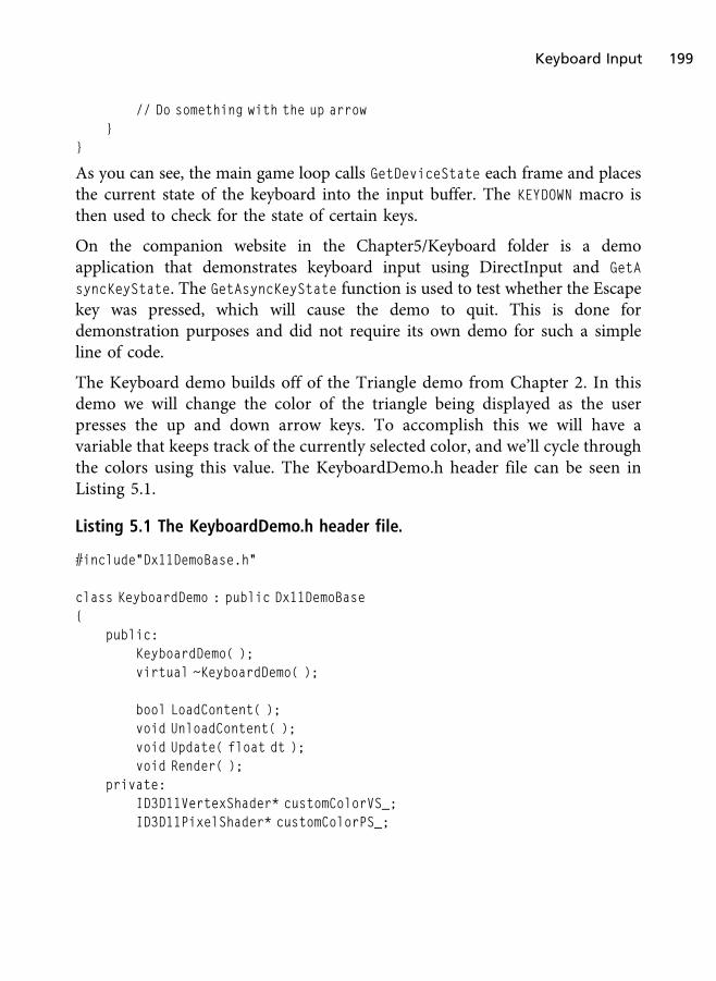
// Do something with the up arrow}
}
As you can see, the main game loop calls GetDeviceState each frame and placesthe current state of the keyboard into the input buffer. The KEYDOWN macro isthen used to check for the state of certain keys.
On the companion website in the Chapter5/Keyboard folder is a demoapplication that demonstrates keyboard input using DirectInput and GetA
syncKeyState. The GetAsyncKeyState function is used to test whether the Escapekey was pressed, which will cause the demo to quit. This is done fordemonstration purposes and did not require its own demo for such a simpleline of code.
The Keyboard demo builds off of the Triangle demo from Chapter 2. In thisdemo we will change the color of the triangle being displayed as the userpresses the up and down arrow keys. To accomplish this we will have avariable that keeps track of the currently selected color, and we’ll cycle throughthe colors using this value. The KeyboardDemo.h header file can be seen inListing 5.1.
Listing 5.1 The KeyboardDemo.h header file.
#include"Dx11DemoBase.h"
class KeyboardDemo : public Dx11DemoBase{
public:KeyboardDemo( );virtual ~KeyboardDemo( );
bool LoadContent( );void UnloadContent( );void Update( float dt );void Render( );
private:ID3D11VertexShader* customColorVS_;ID3D11PixelShader* customColorPS_;
Keyboard Input 199
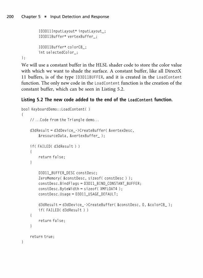
ID3D11InputLayout* inputLayout_;ID3D11Buffer* vertexBuffer_;
ID3D11Buffer* colorCB_;int selectedColor_;
};
We will use a constant buffer in the HLSL shader code to store the color valuewith which we want to shade the surface. A constant buffer, like all DirectX11 buffers, is of the type ID3D11BUFFER, and it is created in the LoadContent
function. The only new code in the LoadContent function is the creation of theconstant buffer, which can be seen in Listing 5.2.
Listing 5.2 The new code added to the end of the LoadContent function.
bool KeyboardDemo::LoadContent( ){
// . . .Code from the Triangle demo. . .
d3dResult = d3dDevice_->CreateBuffer( &vertexDesc,&resourceData, &vertexBuffer_ );
if( FAILED( d3dResult ) ){
return false;}
D3D11_BUFFER_DESC constDesc;ZeroMemory( &constDesc, sizeof( constDesc ) );constDesc.BindFlags = D3D11_BIND_CONSTANT_BUFFER;constDesc.ByteWidth = sizeof( XMFLOAT4 );constDesc.Usage = D3D11_USAGE_DEFAULT;
d3dResult = d3dDevice_->CreateBuffer( &constDesc, 0, &colorCB_ );if( FAILED( d3dResult ) )
{return false;
}
return true;}
200 Chapter 5 n Input Detection and Response
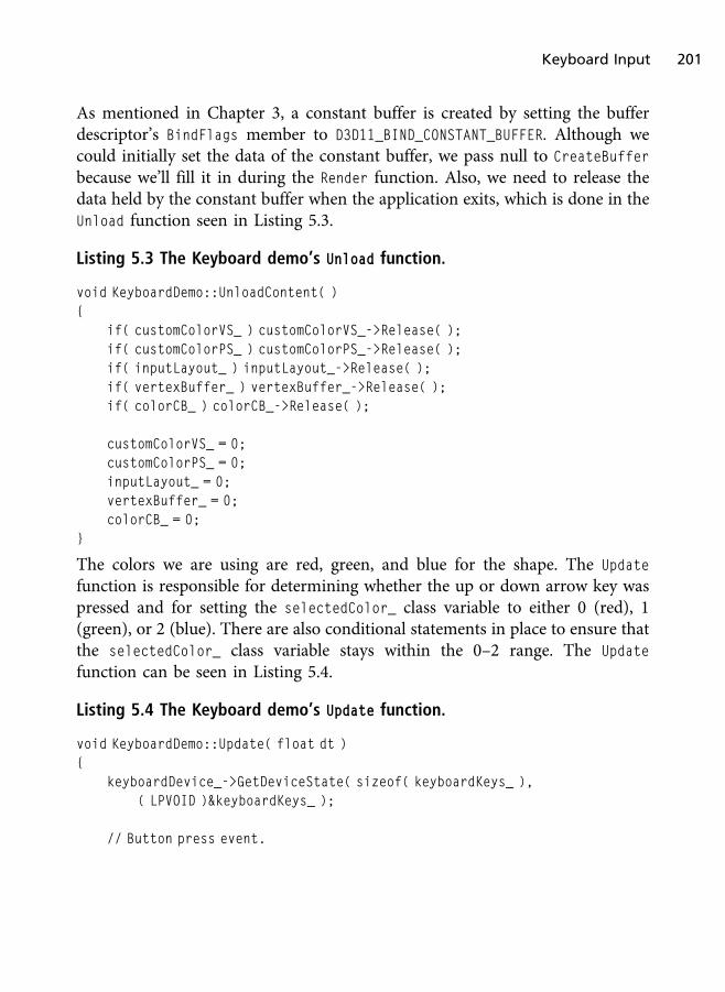
As mentioned in Chapter 3, a constant buffer is created by setting the bufferdescriptor’s BindFlags member to D3D11_BIND_CONSTANT_BUFFER. Although wecould initially set the data of the constant buffer, we pass null to CreateBuffer
because we’ll fill it in during the Render function. Also, we need to release thedata held by the constant buffer when the application exits, which is done in theUnload function seen in Listing 5.3.
Listing 5.3 The Keyboard demo’s Unload function.
void KeyboardDemo::UnloadContent( ){
if( customColorVS_ ) customColorVS_->Release( );if( customColorPS_ ) customColorPS_->Release( );if( inputLayout_ ) inputLayout_->Release( );if( vertexBuffer_ ) vertexBuffer_->Release( );if( colorCB_ ) colorCB_->Release( );
customColorVS_ = 0;customColorPS_ = 0;inputLayout_ = 0;vertexBuffer_ = 0;colorCB_ = 0;
}
The colors we are using are red, green, and blue for the shape. The Update
function is responsible for determining whether the up or down arrow key waspressed and for setting the selectedColor_ class variable to either 0 (red), 1(green), or 2 (blue). There are also conditional statements in place to ensure thatthe selectedColor_ class variable stays within the 0–2 range. The Update
function can be seen in Listing 5.4.
Listing 5.4 The Keyboard demo’s Update function.
void KeyboardDemo::Update( float dt ){
keyboardDevice_->GetDeviceState( sizeof( keyboardKeys_ ),( LPVOID )&keyboardKeys_ );
// Button press event.
Keyboard Input 201

if( GetAsyncKeyState( VK_ESCAPE ) ){
PostQuitMessage( 0 );}
// Button up event.if(KEYDOWN( prevKeyboardKeys_, DIK_DOWN ) &&
!KEYDOWN( keyboardKeys_, DIK_DOWN ) ){
selectedColor_–;}
// Button up event.if(KEYDOWN( prevKeyboardKeys_, DIK_UP ) &&
!KEYDOWN( keyboardKeys_, DIK_UP ) ){
selectedColor_++;}
memcpy( prevKeyboardKeys_, keyboardKeys_, sizeof( keyboardKeys_ ) );
if( selectedColor_ < 0 ) selectedColor_ = 2;if( selectedColor_ > 2 ) selectedColor_ = 0;
}
A key can be either up, pressed, pushed, or released. Although they seemsimilar, they are not. When a button is up, that means it is not being pressed.When a button is being pressed, that means it is being held down. When abutton is pushed, that means it was pressed once but is not being held down.And when a button is released, that means it was down (pushed or beingpressed) but now is up.
This is important when detecting button input from any device. In a game, if theplayer needs to hold down a button to perform some action, such as theacceleration button in a racing game, then we need to know whether the buttonis pressed or not. If the player has to press the button each time the action needsto occur, such as shooting the DMR weapon in Bungie’s Halo Reach, then wedon’t want it to respond to the button being pressed, but instead we only want itto respond when it was pushed once.
202 Chapter 5 n Input Detection and Response

Testing whether a button is up is simply a matter of “if it is not down, then it isup.” To test whether a button is in a pressed state, we have to look at the currentstate of the button and the previous state. If the previous state of the button wasdown, and if the current state of the button is down (or you can say still down),then the button is being pressed.
To test if the button was pressed once, we look to see if the previous state of thebutton was up and the current state of the button is down. If so, then we have asingle pushed event. During the next frame, if the button is still down, the stateswitches from pushed to pressed. This means that pushed would only countonce until the player releases the button and pushes it again.
And finally, to test if the button was released, we need to see if the previous stateof the button was down and the current state of the button is up. If so, we knowthat button was down, and now it is up. This will only occur once because in thenext frame the previous and current states will both equal up.
In the Update function in Listing 5.4 we only want to change colors when the userhas released one of the arrow keys. If we simply checked if the button was down,then the color will rapidly change each frame faster than we can keep up with.
The last demo class level function is the Render function. In this function wesimply fill the constant buffer with the color of red if selectedColor_ is 0, greenif it is 1, and blue if it is 2. The Render function can be seen in Listing 5.5. Thecontent of the constant buffer is updated with a call to the Direct3D context’sUpdateSubresource function.
Listing 5.5 The Render function.
void KeyboardDemo::Render( ){
if( d3dContext_ == 0 )return;
float clearColor[4] = { 0.0f, 0.0f, 0.25f, 1.0f };d3dContext_->ClearRenderTargetView( backBufferTarget_, clearColor );unsigned int stride = sizeof( VertexPos );unsigned int offset = 0;
d3dContext_->IASetInputLayout( inputLayout_ );
Keyboard Input 203

d3dContext_->IASetVertexBuffers( 0, 1, &vertexBuffer_, &stride, &offset );d3dContext_->IASetPrimitiveTopology(D3D11_PRIMITIVE_TOPOLOGY_
TRIANGLELIST);
XMFLOAT4 redColor( 1.0f, 0.0f, 0.0f, 1.0f );XMFLOAT4 greenColor( 0.0f, 1.0f, 0.0f, 1.0f );XMFLOAT4 blueColor( 0.0f, 0.0f, 1.0f, 1.0f );
if( selectedColor_ == 0 ){
d3dContext_->UpdateSubresource( colorCB_, 0, 0, &redColor, 0, 0 );}else if( selectedColor_ == 1 ){
d3dContext_->UpdateSubresource( colorCB_, 0, 0, &greenColor, 0, 0 );}else{
d3dContext_->UpdateSubresource( colorCB_, 0, 0, &blueColor, 0, 0 );}
d3dContext_->VSSetShader( customColorVS_, 0, 0 );d3dContext_->PSSetShader( customColorPS_, 0, 0 );d3dContext_->PSSetConstantBuffers( 0, 1, &colorCB_ );d3dContext_->Draw( 3, 0 );
swapChain_->Present( 0, 0 );}
The shader for this demo can be found in a file called CustomColor.hlsl.Constant buffers in HLSL are defined in a special structure denoted by thekeyword cbuffer, and it is registered to inputs starting at b0 (remember thattextures were registered using t0 and shader resource views with s0).
All variables and objects within a constant buffer can be used as if they areregular global variables. In the Keyboard demo’s shader we create a variablenamed col that is defined within the constant buffer and that will hold theincoming color value. In the pixel shader we simply return this variable, and thecustom color we set on the application side is applied to the rendering. Theshader can be seen in Listing 5.6.
204 Chapter 5 n Input Detection and Response
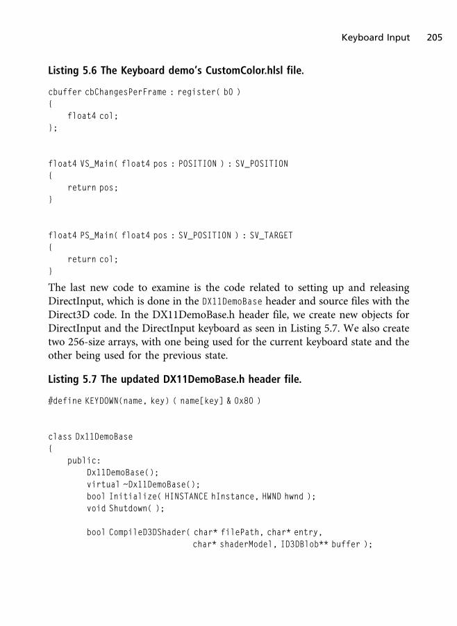
Listing 5.6 The Keyboard demo’s CustomColor.hlsl file.
cbuffer cbChangesPerFrame : register( b0 ){
float4 col;};
float4 VS_Main( float4 pos : POSITION ) : SV_POSITION{
return pos;}
float4 PS_Main( float4 pos : SV_POSITION ) : SV_TARGET{
return col;}
The last new code to examine is the code related to setting up and releasingDirectInput, which is done in the DX11DemoBase header and source files with theDirect3D code. In the DX11DemoBase.h header file, we create new objects forDirectInput and the DirectInput keyboard as seen in Listing 5.7. We also createtwo 256-size arrays, with one being used for the current keyboard state and theother being used for the previous state.
Listing 5.7 The updated DX11DemoBase.h header file.
#define KEYDOWN(name, key) ( name[key] & 0x80 )
class Dx11DemoBase{
public:Dx11DemoBase();virtual ~Dx11DemoBase();bool Initialize( HINSTANCE hInstance, HWND hwnd );void Shutdown( );
bool CompileD3DShader( char* filePath, char* entry,char* shaderModel, ID3DBlob** buffer );
Keyboard Input 205
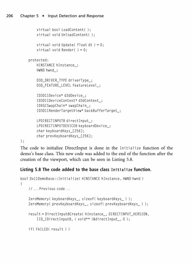
virtual bool LoadContent( );virtual void UnloadContent( );
virtual void Update( float dt ) = 0;virtual void Render( ) = 0;
protected:HINSTANCE hInstance_;HWND hwnd_;
D3D_DRIVER_TYPE driverType_;D3D_FEATURE_LEVEL featureLevel_;
ID3D11Device* d3dDevice_;ID3D11DeviceContext* d3dContext_;IDXGISwapChain* swapChain_;ID3D11RenderTargetView* backBufferTarget_;
LPDIRECTINPUT8 directInput_;LPDIRECTINPUTDEVICE8 keyboardDevice_;char keyboardKeys_[256];char prevKeyboardKeys_[256];
};
The code to initialize DirectInput is done in the Initialize function of thedemo’s base class. This new code was added to the end of the function after thecreation of the viewport, which can be seen in Listing 5.8.
Listing 5.8 The code added to the base class Initialize function.
bool Dx11DemoBase::Initialize( HINSTANCE hInstance, HWND hwnd ){
// . . . Previous code . . .
ZeroMemory( keyboardKeys_, sizeof( keyboardKeys_ ) );ZeroMemory( prevKeyboardKeys_, sizeof( prevKeyboardKeys_ ) );
result = DirectInput8Create( hInstance_, DIRECTINPUT_VERSION,IID_IDirectInput8, ( void** )&directInput_, 0 );
if( FAILED( result ) )
206 Chapter 5 n Input Detection and Response

{return false;
}
result = directInput_->CreateDevice(GUID_SysKeyboard, &keyboardDevice_, 0);
if( FAILED( result ) ){
return false;}
result = keyboardDevice_->SetDataFormat( &c_dfDIKeyboard );
if( FAILED( result ) ){
return false;}
result = keyboardDevice_->SetCooperativeLevel( hwnd_, DISCL_FOREGROUND |DISCL_NONEXCLUSIVE );
if( FAILED( result ) ){
return false;}
result = keyboardDevice_->Acquire( );
if( FAILED( result ) ){
return false;}
return LoadContent( );}
And last but not least we must release DirectInput and the keyboard device,which is done in the base class’ Shutdown function in Listing 5.9.
Keyboard Input 207

Listing 5.9 The base class Shutdown function.
void Dx11DemoBase::Shutdown( ){
UnloadContent( );
if( backBufferTarget_ ) backBufferTarget_->Release( );if( swapChain_ ) swapChain_->Release( );if( d3dContext_ ) d3dContext_->Release( );if( d3dDevice_ ) d3dDevice_->Release( );
if( keyboardDevice_ ){
keyboardDevice_->Unacquire( );keyboardDevice_->Release( );
}
if( directInput_ ) directInput_->Release( );
backBufferTarget_ = 0;swapChain_ = 0;d3dContext_ = 0;d3dDevice_ = 0;keyboardDevice_ = 0;directInput_ = 0;
}
Mouse Input
For the mouse buttons, we also could use the message queue or the various keystate functions while using the virtual codes for the mouse buttons. But asmentioned previously, the message queue is ineffective for video games, so thatis not an option. Along with obtaining the button states of the mouse, we couldalso call the Win32 function GetCursorPos to obtain the mouse’s position. TheGetCursorPos function has the following prototype:
BOOL WINAPI GetCursorPos( LPPOINT lpPoint );
In this section we’ll focus largely on using DirectInput for mouse input.
208 Chapter 5 n Input Detection and Response

DirectInput Mouse Input
Reading input from the mouse is very similar to reading it from the keyboard.The main difference is the GUID passed to the CreateDevice function and theDIDATAFORMAT structure used to hold the input for this device.
In the previous example, the call to CreateDevice used GUID_SysKeyboard as thefirst parameter. When using the mouse, the GUID for CreateDevice must be setto GUID_SysMouse.
No t e
Setting the cooperative level to exclusive mode for mouse input keeps the Windows cursor frombeing displayed. In exclusive mode, you are responsible for drawing the mouse cursor yourself.
hr = directInputObject->CreateDevice( GUID_SysMouse, &mouseDevice, 0 );
if( FAILED( hr ) ){
return FALSE;}
Also, the call to SetDataFormat used the predefined data format c_dfDIKeyboard.This value must be changed to c_dfDIMouse when using the mouse as the inputdevice.
hr = mouseDevice->SetDataFormat( &c_dfDIMouse );
if( FAILED( hr ) ){
return FALSE;}
The final change that needs to be made before you can read from the mouse isthe addition of the DIDATAFORMAT buffer. The keyboard needs a characterbuffer consisting of 256 elements, whereas the mouse needs a buffer of typeDIMOUSESTATE.
The DIMOUSESTATE structure consists of three variables holding the X, Y, and Zpositions of the mouse as well as a BYTE array of four elements for holding thestate of the mouse buttons. The DIMOUSESTATE structure is defined as:
typedef struct DIMOUSESTATE {
Mouse Input 209

LONG lX;LONG lY;LONG lZ;BYTE rgbButtons[4];
} DIMOUSESTATE, *LPDIMOUSESTATE;
Previously, a macro was used to help determine if specific keys on the keyboardhad been pressed. A similar macro can be used to check the state of the mousebuttons.
The X, Y, and Z values in the DIMOUSESTATE structure do not hold the currentposition of the mouse but rather the relative position to where the mousepreviously was. For example, if you moved the mouse slightly to the left about 5pixels, the X value would be �5. If you moved the mouse down 10 pixels, the Yvalue would be 10.
When reading from a mouse, you must keep track of the values read from themouse on the previous frame to be able to correctly interpret the mousemovement.
The following code fragment demonstrates the code needed to read from themouse device. This code handles checking both the movement of the mouseas well as the state of the mouse buttons. In the code fragment we use acustom macro called BUTTONDOWN to test the DIMOUSESTATE to determine if it ispressed. Alternatively, if support for a four-button mouse is needed, then theDIMOUSESTATE2 structure can provide the necessary data.
#define BUTTONDOWN(name, key) ( name.rgbButtons[key] & 0x80 )
curX = 320;curY = 240;
while ( 1 ){
mouseDevice->GetDeviceState( sizeof ( mouseState ), (LPVOID) &mouseState );
if( BUTTONDOWN( mouseState, 0 ) ){
// Do something with the first mouse button}
210 Chapter 5 n Input Detection and Response

if( BUTTONDOWN( mouseState, 1 ) ){
// Do something with the up arrow}
curX += mouseState.lX;curY += mouseState.lY;
}
The Mouse demo can be found on the companion website in the Chapter5/Mouse folder. The demo builds off of the Keyboard demo but adds a mousedevice. This code is essentially the keyboard device code copied and pastedunderneath. The only change is to change the keyboard-specific flags to mouse-specific flags, such as changing c_dfDIKeyboard to c_dfDIMouse.
Listing 5.10 has the Update function from the Mouse demo. The lZ member ofthe mouse state holds the mouse wheel value. If the mouse does not have amouse wheel, this value will remain 0. You can increase or decrease this value toindicate which direction the mouse wheel has moved, whereas the lX and lY
represent the X and Y mouse position changes.
Listing 5.10 The Update function from the Mouse demo.
void MouseDemo::Update( float dt ){
keyboardDevice_->GetDeviceState( sizeof( keyboardKeys_ ),( LPVOID )&keyboardKeys_ );
mouseDevice_->GetDeviceState( sizeof ( mouseState_ ),( LPVOID ) &mouseState_ );
// Button press event.if( GetAsyncKeyState( VK_ESCAPE ) ){
PostQuitMessage( 0 );}
// Button up event.if( KEYDOWN( prevKeyboardKeys_, DIK_DOWN ) &&
!KEYDOWN( keyboardKeys_, DIK_DOWN ) )
Mouse Input 211
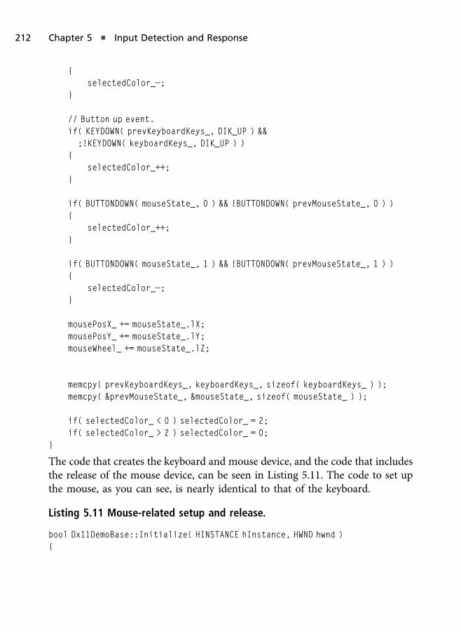
{selectedColor_—;
}
// Button up event.if( KEYDOWN( prevKeyboardKeys_, DIK_UP ) &&
;!KEYDOWN( keyboardKeys_, DIK_UP ) ){
selectedColor_++;}
if( BUTTONDOWN( mouseState_, 0 ) && !BUTTONDOWN( prevMouseState_, 0 ) ){
selectedColor_++;}
if( BUTTONDOWN( mouseState_, 1 ) && !BUTTONDOWN( prevMouseState_, 1 ) ){
selectedColor_—;}
mousePosX_ += mouseState_.lX;mousePosY_ += mouseState_.lY;mouseWheel_ += mouseState_.lZ;
memcpy( prevKeyboardKeys_, keyboardKeys_, sizeof( keyboardKeys_ ) );memcpy( &prevMouseState_, &mouseState_, sizeof( mouseState_ ) );
if( selectedColor_ < 0 ) selectedColor_ = 2;if( selectedColor_ > 2 ) selectedColor_ = 0;
}
The code that creates the keyboard and mouse device, and the code that includesthe release of the mouse device, can be seen in Listing 5.11. The code to set upthe mouse, as you can see, is nearly identical to that of the keyboard.
Listing 5.11 Mouse-related setup and release.
bool Dx11DemoBase::Initialize( HINSTANCE hInstance, HWND hwnd ){
212 Chapter 5 n Input Detection and Response
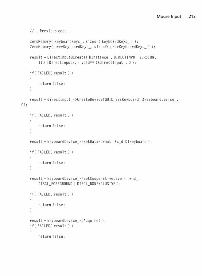
// . . .Previous code. . .
ZeroMemory( keyboardKeys_, sizeof( keyboardKeys_ ) );ZeroMemory( prevKeyboardKeys_, sizeof( prevKeyboardKeys_ ) );
result = DirectInput8Create( hInstance_, DIRECTINPUT_VERSION,IID_IDirectInput8, ( void** )&directInput_, 0 );
if( FAILED( result ) ){
return false;}
result = directInput_->CreateDevice(GUID_SysKeyboard, &keyboardDevice_,0);
if( FAILED( result ) ){
return false;}
result = keyboardDevice_->SetDataFormat( &c_dfDIKeyboard );
if( FAILED( result ) ){
return false;}
result = keyboardDevice_->SetCooperativeLevel( hwnd_,DISCL_FOREGROUND | DISCL_NONEXCLUSIVE );
if( FAILED( result ) ){
return false;}
result = keyboardDevice_->Acquire( );if( FAILED( result ) ){
return false;
Mouse Input 213
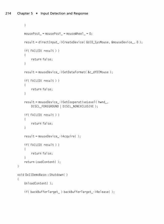
}
mousePosX_ = mousePosY_ = mouseWheel_ = 0;
result = directInput_->CreateDevice( GUID_SysMouse, &mouseDevice_, 0 );
if( FAILED( result ) ){
return false;}
result = mouseDevice_->SetDataFormat( &c_dfDIMouse );
if( FAILED( result ) ){
return false;}
result = mouseDevice_->SetCooperativeLevel( hwnd_,DISCL_FOREGROUND | DISCL_NONEXCLUSIVE );
if( FAILED( result ) ){
return false;}
result = mouseDevice_->Acquire( );
if( FAILED( result ) ){
return false;}return LoadContent( );
}
void Dx11DemoBase::Shutdown( ){
UnloadContent( );
if( backBufferTarget_ ) backBufferTarget_->Release( );
214 Chapter 5 n Input Detection and Response

if( swapChain_ ) swapChain_->Release( );if( d3dContext_ ) d3dContext_->Release( );if( d3dDevice_ ) d3dDevice_->Release( );
if( keyboardDevice_ ){
keyboardDevice_->Unacquire( );keyboardDevice_->Release( );
}
if( mouseDevice_ ){
mouseDevice_->Unacquire( );mouseDevice_->Release( );
}
if( directInput_ ) directInput_->Release( );
backBufferTarget_ = 0;swapChain_ = 0;d3dContext_ = 0;d3dDevice_ = 0;keyboardDevice_ = 0;mouseDevice_ = 0;directInput_ = 0;
}
XInput—Game Controllers
XInput is an input API that is part of the DirectX SDK, XNA Game Studio, andthe XDK (Xbox Developer Kit). XNA Game Studio is a game development toolbuilt on top of DirectX 9 for video game development on Windows PC(Windows XP with Service Pack 1 and higher) and the Xbox 360 video gameconsole. XNA Game Studio is available as a free download from Microsoft andworks with retail Xbox 360 game consoles.
XInput supports a wide range of Xbox game controllers. It also supports voiceinput via the Xbox 360 headset as well as force feedback vibrations. Xbox 360controllers that are compatible with Windows can be used for both the Xbox
XInput—Game Controllers 215

game console and Windows PC video games. In addition to supporting wiredcontrollers via the USB port, wireless controllers are also supported using anXbox 360 wireless controller wireless adapter that is usually found in thecomputer department of most major retailers such as Best Buy. The onlylimitation is that only four controllers can be used at a single time, which ismore a limitation carried over from those controllers being meant for the Xbox360 game console.
The first step is to plug an Xbox 360 controller into your PC. The Windowsoperating system should automatically install the necessary drivers for thedevice immediately. If it does not, you can always download the drivers fromMicrosoft’s website or use the driver CD that came with the controller. Youcan buy Xbox 360 controllers with this driver CD from the computerdepartment of most major retailers. If you already have a wired controllerthat you’ve originally used for your Xbox 360, you can always opt todownload the drivers over the Internet. You can download these driversfrom www.windowsgaming.com.
Also, when writing applications with XInput using the DirectX SDK, we mustinclude the xinput.lib library.
Setting Up XInput
DirectInput had a lot of setup code for the simple tasks it performed. In XInputwe technically don’t have any special initialization code. We can check whetheror not an Xbox 360 controller is attached to the machine by calling the functionXInputGetState. The XInputGetState function has the following functionprototype:
DWORD XInputGetState(DWORD dwUserIndex,XINPUT_STATE* pState
);
The XInputGetState function takes as parameters the player index and the outaddress of the XINPUT_STATE object that will store the state. The player index iszero based, so a value of 0 is for player 1, a value of 1 is for player 2, a value of 2is for player 3, and a value of 3 is for player 4. The controller will have a lightaround the Xbox 360 guide button that indicates which player it is connected to.
216 Chapter 5 n Input Detection and Response

By calling XInputGetState with a player index, we will receive a return value ofERROR_SUCCESS if the controller is plugged in. If the return value is ERROR_DEVI-
CE_NOT_CONNECTED, then the controller is not plugged in. Any other return valueand there is a problem with the device or obtaining its state.
Although we don’t have to set up XInput, we could opt to disable it. This is donewith a call to XInputEnable, which is used for situations when the applicationloses focus (which can occur if the application is minimized). The functionXInputEnable takes a single parameter, which is a flag to enable or disableXInput. False disables XInput while true enables it. When disabled, XInputGetState returns neutral data as if all buttons are up and no input is occurring. Thefunction prototype for XInputEnable has the following look:
void XInputEnable( BOOL enable );
Controller Vibrations
Many Xbox 360 controllers have force feedback capabilities. For game pads thisoccurs via a left and right motor in the controller that causes the device tovibrate. To turn on the controller vibration, we must send to the controller thevibration state with a call to XInputSetState. XInputSetState has the followingfunction prototype:
DWORD XInputSetState(DWORD dwUserIndex,XINPUT_VIBRATION* pVibration
);
The first parameter to the XInputSetState function is a 0–3 player index forplayers 1, 2, 3, or 4. The second parameter is a XINPUT_VIBRATION object, whichhas the following structure:
typedef struct _XINPUT_VIBRATION {WORD wLeftMotorSpeed;WORD wRightMotorSpeed;
} XINPUT_VIBRATION, *PXINPUT_VIBRATION;
The wLeftMotorSpeed is used to set the left motor’s speed and the wRightMo
torSpeed is used to set the right motor’s speed. The values for the motorspeeds range between 0 and 65,535, where 0 is no speed and 65,535 is 100%power.
XInput—Game Controllers 217
XInput for Input
With a call to XInputGetState we have all the information about the currentstate of a controller device. The last parameter of the XInputGetState functionwas an out address to an XINPUT_STATE structure object that contained anXINPUT_GAMEPAD structure with the following structure:
typedef struct _XINPUT_GAMEPAD {WORD wButtons;BYTE bLeftTrigger;BYTE bRightTrigger;SHORT sThumbLX;SHORT sThumbLY;SHORT sThumbRX;SHORT sThumbRY;
} XINPUT_GAMEPAD, *PXINPUT_GAMEPAD;
The wButtons is a bitmask value, meaning that each button can be tested byusing bit operators. There are flags for the arrow pad buttons, the joystickbuttons, the face buttons (buttons A, B, X, and Y), shoulder buttons LB and RB,and the start and select buttons. The joystick buttons are L3 for the left stick andR3 for the right stick, and they are pressed by pushing the joysticks inward. We’llshow how to detect input from face buttons during the XInput demo.
The bLeftTrigger is used for the left trigger button (on top of the game padcontroller), and the bRightTrigger is used for the right trigger. These valuesrange between 0 and 255, where 0 is not pressed, 255 is pressed fully down, andanything between represents how much the trigger is being pressed.
The sThumbLX, sThumbLY, sThumbRX, and sThumbRY values are used for the left andright joystick positions. These values range between �32,768 and 32,767 where, forexample, �32,768 for the left stick’s X-axis represents the stick being moved all theway to the left, and þ32,767 represents that it is pressed all the way to the right.
The XINPUT_GAMEPAD structure will give us all the information needed to detectand respond to input using Xbox 360 game controllers.
Controller Capabilities
Sometimes we might need to know the capabilities of a connected device. Thiscan be achieved with a call to XInputGetCapabilities, which has the followingprototype:
218 Chapter 5 n Input Detection and Response

DWORD XInputGetCapabilities(DWORD dwUserIndex,DWORD dwFlags,XINPUT_CAPABILITIES* pCapabilities
);
The function XInputGetCapabilities takes as parameters the player index, thedevice search flags, and an out address to the structure that holds the device’scapabilities. For the flags we can specify a value of 0 for all device types (e.g.,game pads, steering wheels, etc.), or we can specify XINPUT_FLAG_GAMEPAD to limitthe search to just game pads. Currently XINPUT_FLAG_GAMEPAD is the only flagsupported.
The capabilities are stored in the XINPUT_CAPABILITIES object, which has thefollowing structure:
typedef struct _XINPUT_CAPABILITIES {BYTE Type;BYTE SubType;WORD Flags;XINPUT_GAMEPAD Gamepad;XINPUT_VIBRATION Vibration;
} XINPUT_CAPABILITIES, *PXINPUT_CAPABILITIES;
The first member is the type of device, which currently will only be XINPUT_
DEVTYPE_GAMEPAD.
The second member is the subtype that can further define what type of device itis and can be XINPUT_DEVSUBTYPE_ARCADE_STICK, XINPUT_DEVSUB TYPE_GAMEPAD, orXINPUT_DEVSUBTYPE_WHEEL. If the device is not a game pad, arcade stick, orsteering wheel, it should be treated as if it is just a game pad.
The GAMEPAD member will store the button state of the game pad and the lastmember, the VIBRATION member, will store the current motor speeds of thedevice.
Battery Life
Xbox controllers that are wireless devices can have their battery informationobtained via XInput. This is accomplished with a call to the function XInput
GetBatteryInformation, which has the following function prototype:
XInput—Game Controllers 219
DWORD XInputGetBatteryInformation(DWORD dwUserIndex,BYTE devType,XINPUT_BATTERY_INFORMATION* pBatteryInformation
);
The first parameter to the XInputGetBatteryInformation function is the playerindex, the second parameter is the device type (0 for all types of devices orXINPUT_FLAG_GAMEPAD), and the last parameter is the out address to theXINPUT_BATTERY_INFORMATION object that will store the battery information.The XINPUT_BATTERY_INFORMATION has the following structure:
typedef struct _XINPUT_BATTERY_INFORMATION {BYTE BatteryType;BYTE BatteryLevel;
} XINPUT_BATTERY_INFORMATION, *PXINPUT_BATTERY_INFORMATION;
The BATTERYTYPE member can be one of the following values:
n BATTERY_TYPE_DISCONNECTED for disconnected devices
n BATTERY_TYPE_WIRED for wired devices plugged into the USB port
n BATTERY_TYPE_ALKALINE for devices using alkaline batteries
n BATTERY_TYPE_NIMH for devices using nickel metal hydride batteries
n BATTERY_TYPE_UNKNOWN for devices using an unknown battery types
The BATTERYLEVEL value can be one of the following:
n BATTERY_LEVEL_EMPTY for devices with a dead battery
n BATTERY_LEVEL_LOW for devices low on power
n BATTERY_LEVEL_MEDIUM for devices with mid-levels of power
n BATTERY_LEVEL_FULL for devices with full power
Keystrokes
XInput provides a more general method of obtaining input rather than usingXInputGetState via a function called XInputGetKeystroke. This function is usedto obtain an input event for a connected game pad. The XInputGetKeyStroke hasthe following prototype:
220 Chapter 5 n Input Detection and Response

DWORD XInputGetKeystroke(DWORD dwUserIndex,DWORD dwReserved,PXINPUT_KEYSTROKE pKeystroke
);
The first member is the player index, the second member is the device type weare querying for (either 0 or XINPUT_FLAG_GAMEPAD), and the third member is theout address to the keystroke event. The PXINPUT_KEYSTROKE has the followingstructure:
typedef struct _XINPUT_KEYSTROKE {WORD VirtualKey;WCHAR Unicode;WORD Flags;BYTE UserIndex;BYTE HidCode;
} XINPUT_KEYSTROKE, *PXINPUT_KEYSTROKE;
The virtual key code (VirtualKey) of the XINPUT_KEYSTROKE structure will storethe ID of the button that triggered the event.
The second member is unused and is always 0.
The third member is the flag that triggered the event. This flag can beXINPUT_KEYSTROKE_KEYDOWN if the button was pushed, XINPUT_ KEYSTROKE_KEYUP
if the button was released, and XINPUT_KEYSTROKE_REPEAT if the button is beingheld down.
The fourth member is the player index from 0 to 3 that caused the event, and thelast parameter is an HID code value that future devices might return.
Headset Sound
Many Xbox 360 controllers have a port for the inclusion of an Xbox 360 headset.This headset is primarily used for player-to-player communications over XboxLIVE, the online community and service Microsoft provides for the Xbox 360game console (the Windows equivalent is Games for Windows LIVE). In XInputwe could use the headset’s speaker for audio output and its microphone foraudio input with the help of the XInputGetDSoundAudioDeviceGuids function,which has the following prototype:
XInput—Game Controllers 221
DWORD XInputGetDSoundAudioDeviceGuids(DWORD dwUserIndex,GUID* pDSoundRenderGuid,GUID* pDSoundCaptureGuid
);
The first member is the player index, the second member is the DirectSoundrendering GUID, and the third member is the DirectSound capturing GUID.The GUID is for the headset device rendering (playing) or capturing sound. Aheadset has both a microphone for sound recording and a speaker for soundplayback, and these two devices exist within all standard Xbox 360 headsets.
Using this to work with controller headsets requires knowledge of DirectSound,which is a deprecated audio API in DirectX. The DirectX SDK has samples forusing DirectSound with XInput to capture headset audio.
XInput Demo
The XInput demo, which demonstrates how to detect and respond to gamecontroller button input, can be found on the companion website in theChapter5/XInput folder. This demo is exactly the same as the Keyboard andMouse demos, and the Xinput-specific code can be found in the demo’s Update
function. Since XInput does not need to be explicitly initialized like DirectInput,all of this demo’s specific code takes place in a single function.
The XInput demo class from XInputDemo.h can be seen in Listing 5.12. Like theprevious input demos, we store the previous and current device states to use thecombination to detect key up events.
Listing 5.12 The XInputDemo class.
#include"Dx11DemoBase.h"#include<XInput.h>
class XInputDemo : public Dx11DemoBase{
public:
222 Chapter 5 n Input Detection and Response
XInputDemo( );virtual ~XInputDemo( );
bool LoadContent( );void UnloadContent( );
void Update( float dt );void Render( );
private:ID3D11VertexShader* customColorVS_;ID3D11PixelShader* customColorPS_;
ID3D11InputLayout* inputLayout_;ID3D11Buffer* vertexBuffer_;
ID3D11Buffer* colorCB_;int selectedColor_;
XINPUT_STATE controller1State_;XINPUT_STATE prevController1State_;
};
The Update function starts by obtaining the current device state. If the returnvalue of XInputGetState is ERROR_SUCCESS, then the state was obtainedsuccessfully, and we know that device slot 0, which is player 1, has a deviceplugged in.
The demo uses the back button on the controller to exit the application. Thedemo also uses the face buttons to switch the colors, where the X buttonswitches to blue, the A button switches to green, and the B button switches tored. The triggers in the demo are used to control the left and right motors forvibration. The more you press the triggers, the harder the device will vibrate.
The Update function can be seen in Listing 5.13.
Listing 5.13 The XInputDemo Update function.
void XInputDemo::Update( float dt ){
unsigned long result = XInputGetState( 0, &controller1State_ );
XInput—Game Controllers 223

if( result == ERROR_SUCCESS ){
}
// Button press event.if( controller1State_.Gamepad.wButtons & XINPUT_GAMEPAD_BACK )
{PostQuitMessage( 0 );
}
// Button up event.if( ( prevController1State_.Gamepad.wButtons & XINPUT_GAMEPAD_B ) &&
!( controller1State_.Gamepad.wButtons & XINPUT_GAMEPAD_B ) )
{selectedColor_ = 0;
}
// Button up event.if( ( prevController1State_.Gamepad.wButtons & XINPUT_GAMEPAD_A ) &&
!( controller1State_.Gamepad.wButtons & XINPUT_GAMEPAD_A ) )
{selectedColor_ = 1;
}
// Button up event.if( ( prevController1State_.Gamepad.wButtons & XINPUT_GAMEPAD_X ) &&
!( controller1State_.Gamepad.wButtons & XINPUT_GAMEPAD_X ) ){
selectedColor_ = 2;}
XINPUT_VIBRATION vibration;WORD leftMotorSpeed = 0;WORD rightMotorSpeed = 0;
float leftTriggerVal = ( float )controller1State_.Gamepad.bLeftTrigger;float rightTriggerVal = ( float )controller1State_.Gamepad.bRightTrigger;
224 Chapter 5 n Input Detection and Response

if( controller1State_.Gamepad.bLeftTrigger > 0 ){
leftMotorSpeed = ( WORD )( 65535.0f * ( leftTriggerVal / 255.0f ) );}
if( controller1State_.Gamepad.bRightTrigger > 0 ){
rightMotorSpeed = ( WORD )( 65535.0f * ( rightTriggerVal / 255.0f ) );}
vibration.wLeftMotorSpeed = leftMotorSpeed;vibration.wRightMotorSpeed = rightMotorSpeed;
XInputSetState( 0, &vibration );
memcpy( &prevController1State_, &controller1State_, sizeof(XINPUT_STATE) );}
Summary
Input is an integral part of any game and attention should be paid during thedevelopment cycle. When a game is reviewed, the performance of the input canmake or break it. Always paying proper attention to the input system duringdevelopment will only enhance the gamer’s experience.
In this chapter you saw how to work with keyboards and mice in DirectInput aswell as how to support a wide variety of Xbox 360 game controllers usingXInput. As you can see, XInput is one of the easier DirectX libraries to workwith. Quick and concise user input is vital to any gaming application. Byapplying the XInput functions properly, you’ll enhance the user’s experiencewith your game.
What You Have Learned
In this chapter you learned how to use XInput to read from the Xbox 360controller. You should now understand:
n How to set up and utilize DirectInput for keyboards and mice.
n How to get user input from the Xbox 360 controller.
What You Have Learned 225

n Why you should detect whether the user has removed his controller.
n How to read both analog and digital controls.
n How and when to use vibration.
Chapter Questions
You can find the answers to chapter review questions in Appendix A on thisbook’s companion website.
1. DirectInput allows for what type of input devices?
2. Which function creates the IDirectInput8 interface?
3. Reading from the keyboard requires what kind of buffer?
4. What is the data format type for mouse input?
5. Which function is used to get the current data from a controller?
6. How many controllers can be used at a time?
7. How is controller removal detected?
8. How is user input from a controller disabled?
9. Which structure is used to gather user input?
10. What XInput function allows you to set the vibration of a gamecontroller?
On Your Own
1. Modify the XInput demo to use the GameSprite class from Chapter 3.
2. Build from the first exercise to enable you to move the shape in thescene with the arrow keys.
3. Modify the XInput demo so that the left trigger modulates the red colorchannel based on how hard it is pressed (not pressed will cause red to be0, and fully pressed will cause red to be 100%). Do the same with theright trigger and the blue color component.
226 Chapter 5 n Input Detection and Response
3D Primer
Video games are very mathematics intensive. Everything from graphics, physics,collisions, audio, and so much more requires various levels of mathematics.Whether the application being written is by a beginner or by an experiencedgame developer, math is a subject that cannot be avoided.
Everything you’ve done up to this point has happened in a flat, two-dimensionalenvironment. Your sprites have moved either horizontally or vertically, butthere’s another dimension yet to explore—the third dimension, depth. Sure,some great games can be made that take advantage of only the technology you’veexplored so far, but the latest cutting-edge games take place in a 3D world.
This chapter introduces the concepts and math you’ll need to build a 3D world.DirectX provides a math library that is highly optimized, portable (betweenWindows and the Xbox 360), and very easy to use. Even if you do not havemuch experience with the math topics commonly seen in video games, it can atleast help to understand the math structures and functions available, as well asthe parameters they accept.
In this chapter:
n What coordinate systems are and how they’re used
n How to define points within 3D space
n What vectors are
Chapter 6
227

n The wonderful world of matrices
n How to position and move objects
XNA Math
XNA is not an acronym. XNA Math is the math library that is part of theDirectX 11 SDK. In previous versions of DirectX there was a library calledD3DXMath. This library is still available in the SDK if you link to the DirectX 10and earlier libraries, but it is recommended to learn and use XNA Math.
XNA Math is not to be confused with XNA Game Studio. XNA Game Studio isa C# framework that allows developers to create games for Windows, Zunemedia devices (last supported version was XNA Game Studio 3.1), WindowsPhone 7 mobile devices, and the Xbox 360. Although the math library in theDirectX 11 SDK is called XNA Math, it is not in C# or part of the XNA GameStudio.
To use XNA Math we must include the xnamath.h header file. XNA Math alsoworks on the Xbox 360 with the Xbox SDK.
Utilities
XNA Math has a set of utility functions for raising assertions, calculating theFresnel term, and checking for CPU support. The first function, XMAssert, hasthe following prototype:
VOID XMAssert(CONST CHAR* pExpression, CONST CHAR* pFileName, UNIT LineNumber);
The first parameter to XMAssert is the logical expression being tested. If thislogical expression results in a value of false, the code execution is halted. Thesecond and third parameters to XMAssert are the filename of the code where theassertion was raised from and the line where the call to XMAssert can be foundwithin the source file.
The next function is the one to calculate the Fresnel term, and it has thefollowing function prototype:
XMVECTOR XMFresnelTerm( XMVECTOR CosIncidentAngle, XMVECTOR RefractionIndex );
The Frensel term can be used for various advanced graphical effects. As abeginner, this is not likely to be a function that you will encounter in the near
228 Chapter 6 n 3D Primer
future. The first parameter to the XMFresnelTerm is the cosine values of theincident angles, while the second parameter is the reflection indices for thematerials for the incident angles.
The last function in the utilities section is called XMVerifyCPUSupport, and it hasthe following prototype:
BOOL XMVerifyCPUSupport( );
On Windows, the XMVerifyCPUSupport function is implemented using theWin32 function IsProcessorFeaturePresent to check for the necessary featuresrequired by XNA Math.
Points
Any position within a coordinate system can be represented using a point. Apoint is simply an infinitely small location in space. When locating a point inspace, it is described using a single value for each axis. This value is the offsetfrom the origin along each respective axis. For example, a point located in 2Dspace would need two values, an X and a Y value, to describe its location, such as<1, 3>.
For each axis added, it takes one additional value to represent the point. In 3Dspace, three values, X, Y, and Z, are needed to describe a point, such as <1, 2, 4>.
Points can be used in many ways in the creation of a game, from player positionto the location of a planet. Even though each point is tiny, that one point can beused to represent the location of any object in your game. We have been usingthe position of vertex points to represent the point of a triangle throughout thisbook.
Vectors
Vectors have multiple uses in 3D graphics, from describing distance anddirection to describing speed. Unlike a point, which has only a position, avector has both a direction and a length (magnitude), allowing it to be utilized todetermine which direction a polygon is facing, which direction an object orparticle is heading, or just describe its position. Typically, vectors are designatedas arrows, with a head and tail showing the direction and magnitude. Vectorstypically fall into two categories: free vectors and fixed vectors.
Vectors 229

A free vector is a vector that can be placed in an arbitrary location within acoordinate system, and its meaning doesn’t change.
A fixed vector remains fixed to the origin of the coordinate system. This placesthe tail of these vectors at the origin, while the head is placed at a location inspace. Because fixed vectors are centered on the origin, it allows them to beused to designate a position. This position is comprised of three scalar valuescalled components. The number of components within the vector correspondsto the number of axes. For example, if the coordinate system is describing 3Dspace, then three components are needed to describe a position within it. Forexample, the vector <3, 2, 7> corresponds to a position 3 units away from theorigin on the X axis, 2 units away on the Y axis, and 7 units away on the Zaxis.
The members of a vector are basic data types such as floats, integers, and soforth, and there is one for each axis of the structure. Examples of 2D, 3D, and 4Dvectors can be seen as follows:
struct Vector2{
float x;float y;
};
struct Vector3{
float x;float y;float z;
};
struct Vector4{
float x;float y;float z;float w;
};
230 Chapter 6 n 3D Primer
While you could define these types yourself, the Direct3D structures containmore than just the definitions of the embedded components. In XNA Math wecan represent vectors using XMFLOAT2 for 2D vectors, XMFLOAT3 for 3D vectors,and XMFLOAT4 for 4D vectors. Additional vector types, such as XMHALF4, forexample, are discussed later in this chapter in the section “Structures andTypes.” It is very useful to use the XNA Math library structures because theyare portable (between Windows and the Xbox 360), optimized, and easy touse.
In general when using vectors you’re bound to come across a few different types;here’s a small list:
n Position Vector—A type of vector used to describe a position within acoordinate system, with the tail being at the origin and the head at apoint.
n Normal Vector—A vector perpendicular to a plane. This is useful fordetermining whether a polygon is front or back facing.
n Unit Vectors—Vectors that have a length that equals one. Not all vectorsrequire a large length. When creating a directional light, only the direc-tion of the vector is important.
n Zero Vectors—Vectors with a length of 0.
Another structure available is the XMVECTOR, which is an optimized 4D vector.The XMVECTOR structure is not only mapped to fast hardware registers but is alsoportable and memory aligned.
The implementation of XMVECTOR is platform dependent, and because of thisthere are very efficient functions for accessing data. These functions includeaccessor, store, and loading functions. These functions must be used to safelyaccess the structure’s data in a portable manner.
The first function is a loading function called XMLoadFloat2. This function has aversion for every type of vector, such as XMLoadInt2, XMLoadFloat3, XMLoadByte4,and so forth. The purpose of these functions is to load the corresponding vectortype into an XMVECTOR. This is useful when there were times in code where youwere using, let’s say, XMFLOAT2 for example, and wanted to move that data into anXMVECTOR so that you can perform fast hardware operations on it.
Vectors 231
Each of the loading functions takes as a parameter the address of the vectorwe want to convert to an XMVECTOR. As an example, the function prototype fortaking an XMFLOAT2 and returning a XMVECTOR can be seen in XMLoadFloat2
below:
XMVECTOR XMLoadFloat2( CONST XMFLOAT2* pSource );
The simple answer is that this function copies an XMFLOAT2 to a XMVECTOR,although internally it uses fast instructions to perform the operation. If wewanted to copy a 2D vector to a 4D vector using our custom structures, it wouldlook like the following:
Vector4 dest;Vector2 src;
dest.x = src.x;dest.y = src.y;dest.z = <undefined>;dest.w = <undefined>;
There is a large number of loading functions, and each can be found in the SDKdocumentation. In addition to loading functions we also have storing functions.All functions are identical to one other, with the difference of the first parameter’stype. Using XMStoreFloat2, the function takes as parameters an address to anXMFLOAT2 that will receive the data as its first parameter and the XMVECTOR that hasthe data we want to copy. Its function prototype can be seen as follows:
VOID XMStoreFloat2( XMFLOAT2* pDestination, XMVECTOR V );
The accessor functions can be used to retrieve the value of any member of theXMVECTOR structure. These functions include XMVectorGetX, XMVectorGetY,XMVectorGetZ, and XMVectorGetW. Each of these functions takes as a parameteran XMVECTOR object and returns the value of the corresponding member. Theprototypes of each of these functions can be seen as follows:
FLOAT XMVectorGetX( XMVECTOR V );
FLOAT XMVectorGetY( XMVECTOR V );
FLOAT XMVectorGetZ( XMVECTOR V );
FLOAT XMVectorGetW( XMVECTOR V );
232 Chapter 6 n 3D Primer
Also available are functions that return the value via a pointer as the firstparameter, which can be seen as follows:
VOID XMVectorGetXPtr( FLOAT* x, XMVECTOR V );
VOID XMVectorGetYPtr( FLOAT* y, XMVECTOR V );
VOID XMVectorGetZPtr( FLOAT* z, XMVECTOR V );
VOID XMVectorGetWPtr( FLOAT* w, XMVECTOR V );
And in addition to the functions used to get a member, we also have functionsthat can set them. As an example, the following are the prototypes for the settingof the X member of a XMVECTOR object:
XMVECTOR XMVectorSetX( XMVECTOR V, FLOAT x );XMVECTOR XMVectorSetXPtr( XMVECTOR V, CONST FLOAT* x );
Vector Arithmetic
The most basic operations we can do with vectors are arithmetic operations.Adding, subtracting, multiplying, and dividing vectors with each other is assimple as performing the operation on each member in one vector to thecorresponding member in a second vector. An example of this can be seen withperforming various operations to a 2D vector:
Vector2D a, b, result;
// Addingresult.x = a.x þ b.x;result.y = a.y þ b.y;
// Subtractingresult.x = a.x - b.x;result.y = a.y - b.y;
// Multiplyingresult.x = a.x * b.x;result.y = a.y * b.y;
// Dividingresult.x = a.x / b.x;result.y = a.y / b.y;
Vectors 233
It is also common to perform these operations between a vector and a scalar(floating-point value), as well as using overloaded operators. Although over-loaded operators are convenient to look at in code, they are often less optimalsince they often require multiple functions to be executed (one for the equals,one for the operator, constructors for the vector parameters to the overloadedfunction, etc.) and multiple load/store operations. An example of adding a scalarto a vector or using an overloaded operation can be seen as follows:
Vector2D a, result;float value = 100.0f;
// Adding a floatresult.x = a.x þ value;result.y = a.y þ value;
// Adding as an overloaded operatorresult = a þ value;
In XNA Math we have XMVectorAdd, XMVectorSubtract, XMVectorDivide, andXMVectorMultiply as a means of performing each of these operations betweenXMVECTOR objects. Their prototypes are as follows, and they use optimizedinstruction sets:
XMVECTOR XMVectorAdd( XMVECTOR V1, XMVECTOR V2 );
XMVECTOR XMVectorSubtract( XMVECTOR V1, XMVECTOR V2 );
XMVECTOR XMVectorDivide( XMVECTOR V1, XMVECTOR V2 );
XMVECTOR XMVectorMultiply( XMVECTOR V1, XMVECTOR V2 );
Distance Between Vectors
Occasionally you will need to determine the distance between two points. Thesepoints can be either the origin and a fixed location or two completely arbitrarypoints.
For example, imagine you’re creating a real-time strategy game. Each of themonsters of the opposing army has the opportunity to move toward a commongoal. During the turn of the AI, it can choose to move one of these monsterstoward the goal, but which one? This is where the ability to figure out distance
234 Chapter 6 n 3D Primer

comes in handy. By calculating the relative distance between each monster andthe common goal, the AI can choose which one of the creatures is moreadvantageous to move.
Whether you are determining the distance within a 2D or 3D space, thecalculation is essentially the same. An example can be seen in the followingpseudo code:
Vector2D x1, x2;
float xDistance = x2.x - x1.x;float yDistance = y2.x - y1.x;
float distance = square_root( xDistance * xDistance þ yDistance * yDistance );
In this example x2 is the X axis value of the second vector and x1 is the X axis ofthe first vector. The result of the distance calculation will be a single value thatrepresents the distance between the two points. When determining the distancebetween two points in 3D space, make sure to take the Z value into account aswell.
To put it another way, the distance between one vector and another is the squareroot of the dot product of the vector between the points. We’ll cover dotproducts in the upcoming subsection titled “Dot Product.” The square root ofthe vector between the points is also known as the vector’s length. In this casethe length can be used to give us the distance between vectors.
Determining the Length of a Vector
Occasionally it is useful to know the length of a vector, since the length ormagnitude of the vector can be used as acceleration or velocity when applied to agame object. The length is also used as an input when normalizing the vector.
To calculate the length of a vector, each of the components must be first squaredand then added together. This is known as the dot product. Finally, the squareroot of the dot product is taken to give the output length.
sqrt(vectorX * vectorX þ vectorY * vectorY þ vectorZ * vectorZ);
Direct3D provides several functions to calculate the length of a vector. Thelength of a 2D vector is obtained with a call to XMVector2Length, the length of a3D vector via XMVector3Length, and a 4D vector via XMVector4Length. Additional
Vectors 235

functions also exist to estimate the length of a vector as well as to square thelength. The squared-length functions end with Sq and will essentially performlength � length, while the estimation functions that end with Est are used toincrease performance at the expense of accuracy. All of the length functions inXNA Math can be seen as follows:
XMVECTOR XMVector2Length( XMVECTOR V );XMVECTOR XMVector3Length( XMVECTOR V );XMVECTOR XMVector4Length( XMVECTOR V );
XMVECTOR XMVector2LengthEst( XMVECTOR V );XMVECTOR XMVector3LengthEst( XMVECTOR V );XMVECTOR XMVector4LengthEst( XMVECTOR V );
XMVECTOR XMVector2LengthSq( XMVECTOR V );XMVECTOR XMVector3LengthSq( XMVECTOR V );XMVECTOR XMVector4LengthSq( XMVECTOR V );
Normalize a Vector
Normalizing a vector is the process of reducing any vector into a unit vector,which as you should remember is a vector with a length equal to 1. This is bestdone when only the direction of a vector is needed and the length isunimportant. Vectors can be normalized simply by dividing each of thecomponents by the vector’s length—an example of which can be seen in thefollowing:
Vector3 vec;
float length = Length( vec );
vec.X = vec.X / length;vec.Y = vec.Y / length;vec.Z = vec.Z / length;
The final vector will still point in the same direction, but the length of the vectoris reduced to 1. In XNA Math we have XMVector2Normalize to normalize a 2Dvector, XMVector2NormalizeEst to calculate an estimated normal vector (whichcan lead to a increase of performance at the expense of accuracy), and versionsof each for 3D and 4D vectors. The function prototypes are as follows:
236 Chapter 6 n 3D Primer

XMVECTOR XMVector2Normalize( XMVECTOR V );XMVECTOR XMVector3Normalize( XMVECTOR V );XMVECTOR XMVector4Normalize( XMVECTOR V );
XMVECTOR XMVector2NormalizeEst( XMVECTOR V );XMVECTOR XMVector3NormalizeEst( XMVECTOR V );XMVECTOR XMVector4NormalizeEst( XMVECTOR V );
Cross Product
A cross product of a vector is used to calculate a vector that is perpendicular totwo other vectors. One common use for this is to calculate the normal of atriangle. In this situation you can use the cross product of each edge vector toobtain the triangle’s normal. An edge vector is essentially point A of the triangle� point B for edge 1, and point B � point C for the second edge. The crossproduct is also known as the vector product.
An example of calculating the cross product can be seen in the following, wherea new vector is created by multiplying the components of the two input vectors:
newVectorX = (vector1Y * vector2Z) –(vector1Z * vector2Y);newVectorY = (vector1Z * vector2X) –(vector1X * vector2Z);newVectorZ = (vector1X * vector2Y) –(vector1Y * vector2X);
In XNA Math we have XMVector2Cross, XMVector3Cross, and XMVector4Cross forcalculating the cross product of 2D, 3D, and 4D vectors. Their functionprototypes are as follows:
XMVECTOR XMVector2Cross( XMVECTOR V1, XMVECTOR V2 );XMVECTOR XMVector3Cross( XMVECTOR V1, XMVECTOR V2 );XMVECTOR XMVector4Cross( XMVECTOR V1, XMVECTOR V2 );
Dot Product
The final vector calculation we’ll go over is the dot product. The dot product,also known as the scalar product, is used to determine the angle between twovectors and is commonly used for many calculations in computer graphics suchas back-face culling, lighting, and more.
Back-face culling is the process by which polygons that are not visible areremoved to reduce the number of polygons being drawn. If two vectors have an
Vectors 237

angle less than 90 degrees, then the dot product is a positive value; otherwise, thedot product is negative. The sign of the dot product is what’s used to determinewhether a polygon is front or back facing. If we use the view vector as onevector, the dot product between the view vector and the polygon’s normal tellsus which direction it is facing, and thus which polygons we should draw or not.This is usually handled internally by the graphics hardware and is not anythingwe would do manually when using Direct3D.
We could also use this for lighting, which we’ll discuss in more detail in Chapter 7in the section titled “Lighting.” One way we can use the dot product for lighting isto use the value to see how much diffuse light is reaching the surface. Lightsources directly above a surface will be fully lit, surfaces at an angle will bepartially lit, and surfaces where the light is behind it will receive no light. Thevector used for the dot product is usually the surface normal and the light vector,where the light vector is calculated as the light’s position � the vertex position (orthe pixel’s position when doing per-pixel lighting).
The dot product is calculated by squaring each axis of the vector and addingtogether their results to form a single scalar value. An example of this can beseen in the following:
float dotProduct = vec1.X * vec2.X þ vec1.Y * vec2.Y þ vec1.Z * vec2.Z;
XNA Math has XMVector2Dot for the dot product between 2D vectors,XMVector3Dot for 3D vectors, and XMVector4Dot for 4D vectors. Their proto-types are shown as follows:
XMVECTOR XMVector2Dot( XMVECTOR V1, XMVECTOR V2 );XMVECTOR XMVector3Dot( XMVECTOR V1, XMVECTOR V2 );XMVECTOR XMVector4Dot( XMVECTOR V1, XMVECTOR V2 );
Although the dot product returns a scalar, in XNA Math it seems to bereturning a vector of XMVECTOR. This is because the result is copied into allcomponents of XMVECTOR. Since the optimized instruction set used in XNAMath uses vectors for stream parallel processing, technically that is what weare using even if we ultimately only really use one component. SIMDinstructions work on four floating-point values at a time with a singleinstruction, so in a case such as this we only need to access one of them toget our scalar result.
238 Chapter 6 n 3D Primer

3D Space
The basis to any three-dimensional world is the space it takes place in. Lookaround you. The keyboard and monitor on your desk, the chair on the floor, allof these items exist in a 3D space. If you had to describe the location of one ofthese objects to someone over the phone, how would you do it? Would youdescribe your desk as located in front of you or would you say it was near acertain wall? If the person on the phone knew absolutely nothing about theroom you were in, from that description, would they understand? Probably not;they’re missing a point of reference.
Coordinate Systems
A point of reference is a location that both you and the other person understand.For instance, if the point of reference was a doorway, you could then explain thatthe desk was located about 10 feet from the door on the left side. When you’rebuilding a 3D world, a point of reference is crucial.
You need to be able to place objects in relation to a point of reference that bothyou and the computer understand. When working with 3D graphics, this pointof reference is the coordinate system. A coordinate system is a series ofimaginary lines that run through space and are used to describe locationswithin it. The center of this coordinate system is called the origin; this is the coreof your point of reference. Any location within this space can be describedprecisely in relation to the origin.
For example, you can describe the location of an object by saying it is four unitsup from the origin and two units to the left. By using the origin as the point ofreference, any point within the defined space can be described.
If you remember from working with sprites, any point on the screen can beexplained using X and Y coordinates. The X and Y coordinates determine thesprite’s position in a coordinate system consisting of two perpendicular axes, ahorizontal and a vertical. Figure 6.1 shows an example of a 2D coordinate system.
When working with three dimensions, a third axis will be needed: the Z axis.The Z axis extends away from the viewer, giving the coordinate system a way todescribe depth. So now you have three dimensions, width, height, and depth, aswell as three axes.
3D Space 239

When dealing with 3D coordinate systems, you have to be aware that they comein two flavors: left-handed and right-handed. The handedness of the systemdetermines the direction the axes face in relation to the viewer.
Left-Handed Coordinate Systems
A left-handed coordinate system extends the positive X axis to the left and thepositive Y axis upward. The Z axis in a left-handed system is positive in thedirection away from the viewer, with the negative portion extending towardthem. Figure 6.2 shows how a left-handed coordinate system is set up.
Figure 6.1
A 2D coordinate system.
Figure 6.2
A left-handed coordinate system.
240 Chapter 6 n 3D Primer

Right-Handed Coordinate Systems
The right-handed coordinate system extends the X and Y axes similarly to theleft-handed system, but it reverses the X and Z axis directions. The positive Zvalues extend toward the viewer, whereas the negative values continue away. Forthe X axis, the positive X axis increases to the right, whereas the positive X axisin the left-handed system is to the left. Figure 6.3 shows a right-handed system.
Transformations
3D models are for the most part created outside of your game code. Forinstance, if you’re creating a racing game, you’ll probably create the car modelsin a 3D art package. During the creation process, these models will be workingoff of the coordinate system provided to them in the modeler. This causes theobjects to be created with a set of vertices that aren’t necessarily going to placewhere the model will end up in the game and how you want it oriented in yourgame environment. Because of this, you will need to move and rotate the modelyourself. You can do this by using the geometry pipeline. The geometry pipelineis a process that allows you to transform an object from one coordinate systeminto another. Figure 6.4 shows the transformations a vertex goes through.
When a model starts out, it is centered on the origin. This causes the model to becentered in the environment with a default orientation. Not every model youload needs to be at the origin, so how do you get models where they need to be?The answer to that is through transformations.
Figure 6.3
A right-handed coordinate system.
3D Space 241

Transformations refer to the actions of translating (moving), rotating, andscaling an object. By applying these actions, you can make an object appear tomove around. These actions are handled as your objects progress through thestages of the geometry pipeline.
When you load a model, its vertices are in a local coordinate system calledmodel space. Model space refers to a coordinate system where the parts of anobject are relative to a local origin. For instance, upon creation, a model’svertices are in reference to the origin point around which they were created. Acube that is two units in size centered on the origin would have its vertices oneunit on either side of the origin. If you then wanted to place this cubesomewhere within your game, you would need to transform its vertices frommodel space into the global system used by all the objects in your world. Thisglobal coordinate system is called world space, where all objects are relative to asingle fixed origin. The process of transforming an object from model space intoworld space is called the world transformation.
World Transformations
The world transformation stage of the geometry pipeline takes an existing objectwith its own local coordinate system and transforms that object into the world
Figure 6.4
Geometry pipeline.
242 Chapter 6 n 3D Primer

coordinate system. The world coordinate system is the system that contains theposition and orientation of all objects within the 3D world. The world systemhas a single origin point that all models transformed into this system becomerelative to.
The transformation from model space to world space usually occurs within thevertex shader when it comes to rendering geometry. You could transform thegeometry yourself outside of shaders, but that will require repopulating vertexbuffers with dynamic information, which would not always be the best course ofaction (especially for static geometry).
The next stage of the geometry pipeline is the view transformation. Because allobjects at this point are relative to a single origin, you can only view them fromthis point. To allow you to view the scene from any arbitrary point, the objectsmust go through a view transformation.
View Transformations
The view transformation transforms the coordinates from world space into viewspace. View space refers to the coordinate system that is relative to the positionof a virtual camera. In other words, the view transformation is used to simulate acamera that is applied to all objects in the game world with the exception of thegraphical user interface (e.g., screen elements for the health bar, timers, ammocounter, etc.). When you choose a point of view for your virtual camera, thecoordinates in world space get reoriented in respect to the camera. For instance,the camera remains at the origin, while the world itself is moved into thecamera’s view.
At this point, you have the camera angle and view for your scene, and you’reready to display it to the screen.
Projection Transformations
The next stage in the geometry pipeline is the projection transformation. Theprojection transformation is the stage of the pipeline where depth is applied.When you cause objects that are closer to the camera to appear larger than thosefarther away, you create an illusion of depth. This type of projection is known asperspective projection and is used for 3D games. Another type of projection willkeep all rendered objects looking like they are the same distance apart from each
3D Space 243
other even when they are not. This is done through orthographic projection. Afinal type of projection is isometric projection, which is a projection used todisplay 3D objects in 2D technical drawings. This type of projection is simulatedand not actually done in graphics APIs, where we usually just have eitherperspective projection or orthographic projection.
Finally, the vertices are scaled to the viewport and projected into 2D space. Theresulting 2D image appears on your monitor with the illusion of being a 3D scene.
Transforming an Object
Now that you’re aware of the transformations, what are they really used for? Asan example, say you were modeling a city. This city is made up of houses, officebuildings, and a few cars here and there. Now, you load in a model of a new carand need to add it to your existing scene. When the model comes in, though, it’scentered on the origin and facing the wrong way. To get the car to the correctspot and orientation in the scene, the car model will have to be rotated properlyand then translated to its world space location.
When putting an object through the transformation pipeline, you’re reallytransforming each vertex individually. In the case of the car, every vertex thatmakes up the car will be moved individually by a certain amount and thenrotated. After each vertex is complete, the object appears in the new position.These transformations take place by multiplying each vertex in the model by atransformation matrix.
The world matrix used for the world transformation is created by combining thescale, rotation, and translation (positioning) matrices for that specific gameobject. Although we usually use these three matrices to create the world matrix,if the object doesn’t use one or more of these properties, you could just leave itout, since combining one matrix with an identity matrix is similar to multiplyinga number by 1; it doesn’t change its value. An identity matrix is similar to amatrix with nothing applied to it.
Combining the world matrix and the view matrix will create a new matrix calledthe world-view matrix. Combining the world-view and projection matrices willcreate another matrix called the world-view-projection matrix. This matrix isoften used by the vertex shader and is the one we’ve been working withthroughout this book.
244 Chapter 6 n 3D Primer

Transforming a vector by a transformation matrix is done by multiplying thevector by the matrix. This is an operation we’ve done in the large majority ofdemos in the vertex shader where we used the HLSL keyword mul to performthe multiplication. In XNA Math we can call, using 2D vectors as an example,the function XMVector2Transform to transform a vector by a matrix. There isalso a version of this called XMVector2TransformCoord, which is used totransform a vector and then project it onto w = 1. The third type oftransformation function, called XMVector2TransformNormal, is used to trans-form a vector by all parts of the matrix with the exception of its translationalpart. Each of these types of functions for 2D, 3D, and 4D vectors can be seenas follows:
XMVECTOR XMVector2Transform( XMVECTOR V, XMMATRIX M );XMVECTOR XMVector3Transform( XMVECTOR V, XMMATRIX M );XMVECTOR XMVector4Transform( XMVECTOR V, XMMATRIX M );
XMVECTOR XMVector2TransformCoord( XMVECTOR V, XMMATRIX M );XMVECTOR XMVector3TransformCoord( XMVECTOR V, XMMATRIX M );XMVECTOR XMVector4TransformCoord( XMVECTOR V, XMMATRIX M );
XMVECTOR XMVector2TransformNormal( XMVECTOR V, XMMATRIX M );XMVECTOR XMVector3TransformNormal( XMVECTOR V, XMMATRIX M );XMVECTOR XMVector4TransformNormal( XMVECTOR V, XMMATRIX M );
There is also a stream version of each of these functions. Using the 2D vectorversion of this function as an example, the parameters include the address to theoutput array the data will be saved, the size in bytes between each output vector,the input array of vectors you are supplying to be transformed, the size in bytesbetween each input vector, the total number of vectors being transformed, andthe matrix by which these vectors will be transformed. The function prototypefor the XMVector2TransformStream function can be seen as follows:
XMFLOAT4* XMVector2TransformStream(XMFLOAT4 *pOutputStream,UINT OutputStride,CONST XMFLOAT2 *pInputStream,UINT InputStride,UINT VectorCount,XMMATRIX M
);
3D Space 245
An alternative to XMVector2Transform is XMVector2TransformNC, where NC refersto non-cached memory.
Matrices
You’ve probably come across matrices in a math class along the way andwondered what they would ever be used for. Well, here it is: game programming.Matrices are used to transform objects from one coordinate system to another.By applying a matrix to an existing point, it is transformed from its originalcoordinate system to the new one. For example, most objects start out in theirown local coordinate system. This means that all the points that make up thatobject are relative to a local origin. To convert those points into a commonworld coordinate system, they must be transformed using a matrix.
You will probably find matrices to be the single most confusing concept to wrapyour thoughts around when just starting out with 3D graphics. Matrices and themath involved can feel very daunting and overwhelming at the start. Theimportant thing to take away from this section on matrices isn’t necessarily howthey work, but what they’re for and how to use them. No one should expect youto be able to perform all the math required right off the bat; luckily, Direct3Dprovides optimized functionality to do a lot of this work for you. If you everwant to know all the details behind matrices, there is a ton of good mathresources available on the web. Simply put, a matrix is used to represent asystem of values where, in the case of graphics and game programming, we usethese objects to store the necessary information to transform vectors to thesystem the matrix represents.
Mathematically, a matrix is a 4� 4 grid of numbers that are arranged incolumns and rows. Each row in the matrix corresponds to the three major axes.The first row is used for the X axis, the second row for the Y axis, and the thirdrow for the Z axis. The final row is used to contain the translation offset values.
If you wanted to create your own matrix in code, you could define it as a simple4� 4 array of float values.
float matrix [4][4] ={
1.0f, 0.0f, 0.0f, 0.0f,0.0f, 1.0f, 0.0f, 0.0f,
246 Chapter 6 n 3D Primer
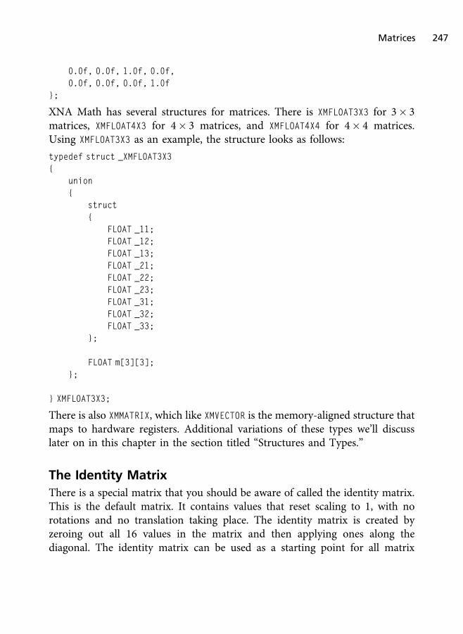
0.0f, 0.0f, 1.0f, 0.0f,0.0f, 0.0f, 0.0f, 1.0f
};
XNA Math has several structures for matrices. There is XMFLOAT3X3 for 3� 3matrices, XMFLOAT4X3 for 4� 3 matrices, and XMFLOAT4X4 for 4� 4 matrices.Using XMFLOAT3X3 as an example, the structure looks as follows:
typedef struct _XMFLOAT3X3{
union{
struct{
FLOAT _11;FLOAT _12;FLOAT _13;FLOAT _21;FLOAT _22;FLOAT _23;FLOAT _31;FLOAT _32;FLOAT _33;
};
FLOAT m[3][3];};
} XMFLOAT3X3;
There is also XMMATRIX, which like XMVECTOR is the memory-aligned structure thatmaps to hardware registers. Additional variations of these types we’ll discusslater on in this chapter in the section titled “Structures and Types.”
The Identity Matrix
There is a special matrix that you should be aware of called the identity matrix.This is the default matrix. It contains values that reset scaling to 1, with norotations and no translation taking place. The identity matrix is created byzeroing out all 16 values in the matrix and then applying ones along thediagonal. The identity matrix can be used as a starting point for all matrix
Matrices 247
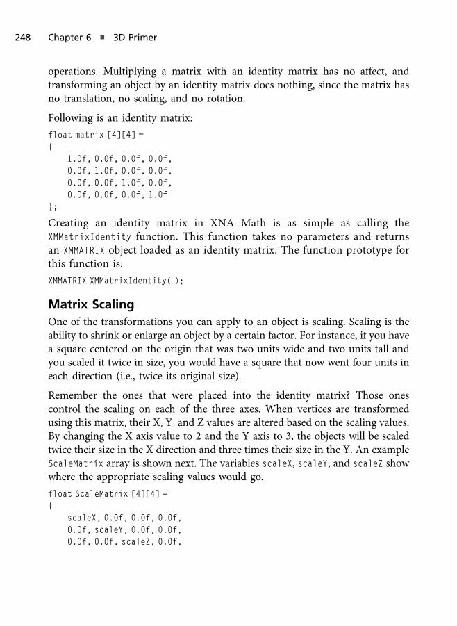
operations. Multiplying a matrix with an identity matrix has no affect, andtransforming an object by an identity matrix does nothing, since the matrix hasno translation, no scaling, and no rotation.
Following is an identity matrix:
float matrix [4][4] ={
1.0f, 0.0f, 0.0f, 0.0f,0.0f, 1.0f, 0.0f, 0.0f,0.0f, 0.0f, 1.0f, 0.0f,0.0f, 0.0f, 0.0f, 1.0f
};
Creating an identity matrix in XNA Math is as simple as calling theXMMatrixIdentity function. This function takes no parameters and returnsan XMMATRIX object loaded as an identity matrix. The function prototype forthis function is:
XMMATRIX XMMatrixIdentity( );
Matrix Scaling
One of the transformations you can apply to an object is scaling. Scaling is theability to shrink or enlarge an object by a certain factor. For instance, if you havea square centered on the origin that was two units wide and two units tall andyou scaled it twice in size, you would have a square that now went four units ineach direction (i.e., twice its original size).
Remember the ones that were placed into the identity matrix? Those onescontrol the scaling on each of the three axes. When vertices are transformedusing this matrix, their X, Y, and Z values are altered based on the scaling values.By changing the X axis value to 2 and the Y axis to 3, the objects will be scaledtwice their size in the X direction and three times their size in the Y. An exampleScaleMatrix array is shown next. The variables scaleX, scaleY, and scaleZ showwhere the appropriate scaling values would go.
float ScaleMatrix [4][4] ={
scaleX, 0.0f, 0.0f, 0.0f,0.0f, scaleY, 0.0f, 0.0f,0.0f, 0.0f, scaleZ, 0.0f,
248 Chapter 6 n 3D Primer

0.0f, 0.0f, 0.0f, 1.0f};
In XNA Math we can use the function XMMatrixScaling to create a scalingmatrix. This function takes as parameters the X, Y, and Z scaling factors andreturns an XMMATRIX that represents this scale in matrix form. The functionprototype can be seen as follows:
XMMATRIX XMMatrixScaling( FLOAT ScaleX, FLOAT ScaleY, FLOAT ScaleZ );
Matrix Translation
The act of moving an object is called translation. Translation allows for an objectto be moved along any of the three axes by specifying the amount of movementneeded. For example, if you want to move an object right along the X axis, youwould need to translate that object an appropriate number of units in thepositive X direction. To do so, you would need to create a translation matrix.
Again, we’ll start with the identity matrix and change it to add in the variablesthat affect translation. Take a look at the following translation matrix; thevariables moveX, moveY, and moveZ show you where the translation values wouldgo. If you wanted to translate an object four units to the right, you would replacemoveX with the value 4.
float matrix [4][4] ={
1.0f, 0.0f, 0.0f, 0.0f,0.0f, 1.0f, 0.0f, 0.0f,0.0f, 0.0f, 1.0f, 0.0f,moveX, moveY, moveZ, 1.0f
};
In XNAMath we create a translation matrix by calling XMMatrixTranslation,which takes as parameters the X, Y, and Z translation values and has thefollowing function prototype:
XMMATRIX XMMatrixTranslation( FLOAT OffsetX, FLOAT OffsetY, FLOAT OffsetZ );
Matrix Rotation
The final effect we’ll describe is rotation. Rotation is the act of turning an objectaround a certain axis. This allows objects to change their orientation within
Matrices 249

space. For instance, if you wanted to rotate a planet, you would create a rotationmatrix and apply it to the planet.
Rotation matrices take a little more explanation because the matrix needs tochange based on the axis you’re trying to rotate around.
When rotating around any axis, it will require you to convert the angle ofrotation into both a sine and a cosine value. These values are then plugged intothe matrix to cause the proper amount of rotation. When rotating around theX axis, the sine and cosine values are placed into the matrix in the followingmanner.
float rotateXMatrix[4][4] ={
1.0f, 0.0f, 0.0f, 0.0f0.0f, cosAngle, sinAngle, 0.0f,0.0f, -sinAngle, cosAngle, 0.0f,0.0f, 0.0f, 0.0f, 1.0f
};
Rotating around the Y axis requires only that the sine and cosine values bemoved to different positions within the matrix. In this instance, the values aremoved to affect the X and Z axes as shown in the following manner.
float rotateYMatrix[4][4] ={
cosAngle, 0.0f, -sinAngle, 0.0f,0.0f, 1.0f, 0.0f, 0.0f,sinAngle, 0.0f, cosAngle, 0.0f,0.0f, 0.0f, 0.0f, 1.0f
};
The final rotation matrix allows for rotation around the Z axis. In this instance,the sine and cosine values affect the X and Y axes.
float rotateZMatrix[4][4] ={
cosAngle, sinAngle, 0.0f, 0.0f,-sinAngle, cosAngle, 0.0f, 0.0f,0.0f, 0.0f, 1.0f, 0.0f,0.0f, 0.0f, 0.0f, 1.0f
};
250 Chapter 6 n 3D Primer
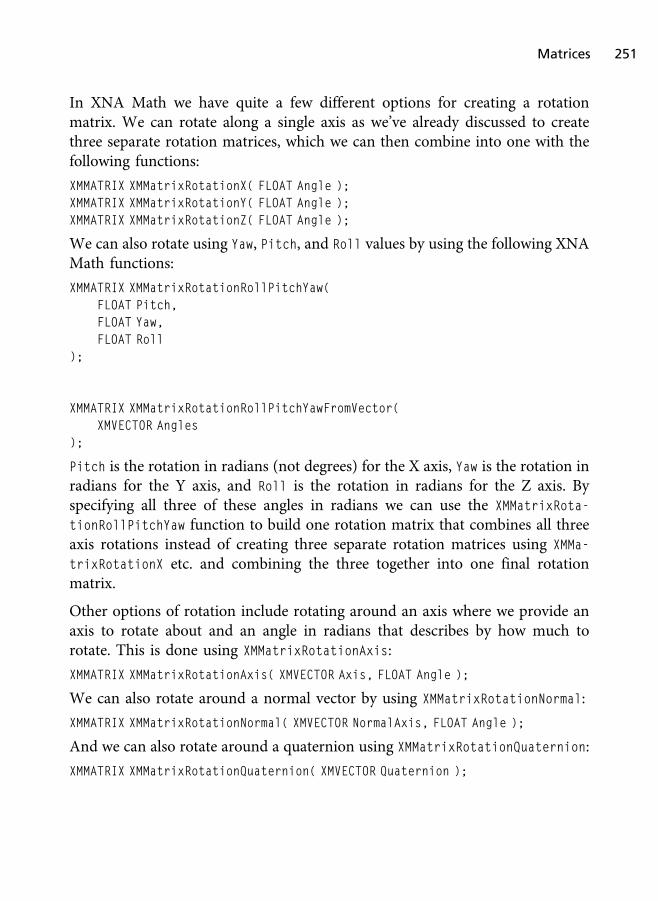
In XNA Math we have quite a few different options for creating a rotationmatrix. We can rotate along a single axis as we’ve already discussed to createthree separate rotation matrices, which we can then combine into one with thefollowing functions:
XMMATRIX XMMatrixRotationX( FLOAT Angle );XMMATRIX XMMatrixRotationY( FLOAT Angle );XMMATRIX XMMatrixRotationZ( FLOAT Angle );
We can also rotate using Yaw, Pitch, and Roll values by using the following XNAMath functions:
XMMATRIX XMMatrixRotationRollPitchYaw(FLOAT Pitch,FLOAT Yaw,FLOAT Roll
);
XMMATRIX XMMatrixRotationRollPitchYawFromVector(XMVECTOR Angles
);
Pitch is the rotation in radians (not degrees) for the X axis, Yaw is the rotation inradians for the Y axis, and Roll is the rotation in radians for the Z axis. Byspecifying all three of these angles in radians we can use the XMMatrixRota-
tionRollPitchYaw function to build one rotation matrix that combines all threeaxis rotations instead of creating three separate rotation matrices using XMMa-
trixRotationX etc. and combining the three together into one final rotationmatrix.
Other options of rotation include rotating around an axis where we provide anaxis to rotate about and an angle in radians that describes by how much torotate. This is done using XMMatrixRotationAxis:
XMMATRIX XMMatrixRotationAxis( XMVECTOR Axis, FLOAT Angle );
We can also rotate around a normal vector by using XMMatrixRotationNormal:
XMMATRIX XMMatrixRotationNormal( XMVECTOR NormalAxis, FLOAT Angle );
And we can also rotate around a quaternion using XMMatrixRotationQuaternion:
XMMATRIX XMMatrixRotationQuaternion( XMVECTOR Quaternion );
Matrices 251
A quaternion is another mathematical object we can use to represent rotation ingraphics programming. The topic of quaternions is more advanced thanmatrices and is definitely something you will encounter when you touch uponadvanced character animation techniques, such as skinned animation usingbones (skeleton).
Matrix Concatenation
The last thing you need to learn about matrices is how to combine them. Mostof the time, you won’t need to only translate an object, you’ll need to scale itor maybe rotate it all in one go. Multiple matrices can be multiplied, orconcatenated, together to create a single matrix that is capable of containingthe previously single calculations. This means that instead of needing a matrixfor rotation as well as one for translation, these two can be combined intoone.
Depending on the platform and intrinsic used, in XNA Math we could use theoverloaded multiplication operator. The following single line of code demon-strates this.
XMMATRIX finalMatrix = rotationMatrix * translationMatrix;
A new matrix called finalMatrix is created, which now contains both therotation and translation. This new matrix can then be applied to any objectgoing through the pipeline. One thing to mention though is to watch out for theorder in which you multiply matrices. Using the previous line of code, objectswill be rotated first and then translated away from that position. For example,rotating the object 90 degrees around the Y axis and then translating it four unitsalong the X axis would cause the object to be rotated in place at the origin andthen moved four units to the right. When creating a world matrix, you shouldcombine the various matrices as scaling� rotation� translation.
If the translation appeared first, the object would be translated four units to theright of the origin first and then rotated 90 degrees. Think what would happen ifyou extended your hand to your right and then turned your body 90 degrees—where would your hand end up? Not exactly in the same place as before; youneed to make sure that the order in which you multiply the matrices is the orderyou really want them applied.
252 Chapter 6 n 3D Primer

In XNA Math we can also multiply matrices using the function XMMatrixMul-
tiply, which takes as parameters two matrices to multiply together and returnsthe resulting matrix. Its prototype can be seen as follows:
XMMATRIX XMMatrixMultiply( XMMATRIX M1, XMMATRIX M2 );
Matrix concatenation is another term for matrix multiplication.
Cube Demo
In this chapter we will create our first true 3D demo, called the Cube demo,which is located on the companion website in the Chapter6/CubeDemo folder.By “first true 3D demo” we are referring to the fact that all demos up to thispoint have created a flat-colored or textured surface (e.g., triangles, sprites, etc.).Although technically these demos are 3D, since there was nothing to stop usfrom utilizing the Z axis of the vertices, we did not create a mesh with an actualvolume. Let’s start with the “Hello World” of 3D demos by creating a 3D cube.
To begin we will update our base DirectX 11 class by adding a depth/stencilview. This is related to depth and stencil testing. A stencil buffer is usedprimarily to render to a destination where you can increment or decrement thevalues in the buffer for pixels that passed the stencil test. This is often used formore advanced rendering topics, with one very famous technique being stencilshadow volumes.
Depth testing, as we mentioned in Chapter 2, is used to ensure that surfaces areproperly drawn and displayed in the correct order without the need to sortpolygons. For example, if we have two triangles with the same X and Y axis butseparated by 100 units along the Z axis, then the triangles are not touching oroverlapping. If we draw the closer triangle first and the further triangle second,the second triangle’s color data will overwrite the triangle that is closer to thecamera. This is not what we want, and if we want to draw those trianglesproperly, where the closer one is displayed to be closer than the further triangle,we’d have to spend precious resources sorting those polygons so we know theproper rendering order.
But sorting polygons is no cheap operation, and a scene can have millions ofthem, or at least thousands, that are visible in any given frame. The depth bufferis a simple concept that eliminates the need to presort all polygons before
Cube Demo 253

submitting them to the graphics hardware. Every time a surface is rendered, itsvertices are transformed by the model-view projection matrix. The depth of eachof these vertices as well as the interpolated depths of the pixels that lie within thesurface is calculated by the hardware. The depth buffer stores the depths for eachrendered pixel as long as the depth is determined (by hardware) to be closer tothe viewer than what was previously rendered. If the depth is closer, then thevarious buffers are updated appropriately. In other words, the final renderedscene’s color buffer, depth buffer, and whatever other destination targetsattached are updated for those pixels that pass the depth test. Pixels that donot pass the depth test are discarded.
No t e
Early 3D games like Wolfenstein 3D by Id Software were sorting polygons before rendering thescenes. This was one of the early uses for Binary Space Partitioning (BSP) Trees.
We can represent a depth/stencil view as an ID3D11DepthStencilView object. Aswe already know, in Direct3D a view is simply a way for our hardware to accessa resource. In the case of a depth buffer that resource is going to be a 2D texture,and that means that in addition to creating a new ID3D11DepthStencilView
object in our base class, we’ll also need to create a ID3D11Texture2D object tostore the contents of the depth buffer. Listing 6.1 shows our updated Dx11De-
moBase class definition, where the new objects for a ID3D11DepthStencilView anda ID3D11Texture2D are added as member pointers.
Listing 6.1 Our updated Dx11DemoBase class that includes depth bufferobjects.
class Dx11DemoBase{
public:Dx11DemoBase( );virtual ~Dx11DemoBase( );
bool Initialize( HINSTANCE hInstance, HWND hwnd );void Shutdown( );
254 Chapter 6 n 3D Primer

bool CompileD3DShader( char* filePath, char* entry,char* shaderModel, ID3DBlob** buffer );
virtual bool LoadContent( );virtual void UnloadContent( );
virtual void Update( float dt ) = 0;virtual void Render( ) = 0;
protected:HINSTANCE hInstance_;HWND hwnd_;
D3D_DRIVER_TYPE driverType_;D3D_FEATURE_LEVEL featureLevel_;
ID3D11Device* d3dDevice_;ID3D11DeviceContext* d3dContext_;IDXGISwapChain* swapChain_;ID3D11RenderTargetView* backBufferTarget_;
ID3D11Texture2D* depthTexture_;ID3D11DepthStencilView* depthStencilView_;
};
The base class’s Initialize function must be updated to create the depth buffer.In Listing 6.2 we will omit the code from the Initialize function that we’vebeen using in every demo of this book and only focus on the code that is new.This new code includes creating the 2D texture, creating the depth/stencil view,and attaching that view to Direct3D.
We create the 2D texture that will act as the depth buffer by simply filling out aD3D11_TEXTURE2D_DESC object with the properties necessary for the depth buffer.The depth buffer must match our rendering width and height, have a bind flagof D3D11_BIND_DEPTH_STENCIL, allow for default usage, and have a format ofDXGI_FORMAT_D24_UNORM_S8_UINT. The format essentially says that we are using24 bits for a single component that will store the depth. Since a depth is a singlevalue, we do not need an RGB or RGBA texture image and only need to create asingle component (R) texture.
Cube Demo 255
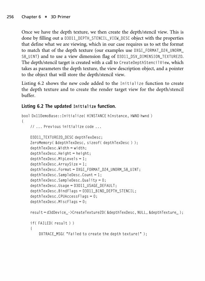
Once we have the depth texture, we then create the depth/stencil view. This isdone by filling out a D3D11_DEPTH_STENCIL_VIEW_DESC object with the propertiesthat define what we are viewing, which in our case requires us to set the formatto match that of the depth texture (our examples use DXGI_FORMAT_D24_UNORM_
S8_UINT) and to use a view dimension flag of D3D11_DSV_DIMENSION_TEXTURE2D.The depth/stencil target is created with a call to CreateDepthStencilView, whichtakes as parameters the depth texture, the view description object, and a pointerto the object that will store the depth/stencil view.
Listing 6.2 shows the new code added to the Initialize function to createthe depth texture and to create the render target view for the depth/stencilbuffer.
Listing 6.2 The updated Initialize function.
bool Dx11DemoBase::Initialize( HINSTANCE hInstance, HWND hwnd ){
// ... Previous initialize code ...
D3D11_TEXTURE2D_DESC depthTexDesc;ZeroMemory( &depthTexDesc, sizeof( depthTexDesc ) );depthTexDesc.Width = width;depthTexDesc.Height = height;depthTexDesc.MipLevels = 1;depthTexDesc.ArraySize = 1;depthTexDesc.Format = DXGI_FORMAT_D24_UNORM_S8_UINT;depthTexDesc.SampleDesc.Count = 1;depthTexDesc.SampleDesc.Quality = 0;depthTexDesc.Usage = D3D11_USAGE_DEFAULT;depthTexDesc.BindFlags = D3D11_BIND_DEPTH_STENCIL;depthTexDesc.CPUAccessFlags = 0;depthTexDesc.MiscFlags = 0;
result = d3dDevice_->CreateTexture2D( &depthTexDesc, NULL, &depthTexture_ );
if( FAILED( result ) ){
DXTRACE_MSG( "Failed to create the depth texture!" );
256 Chapter 6 n 3D Primer
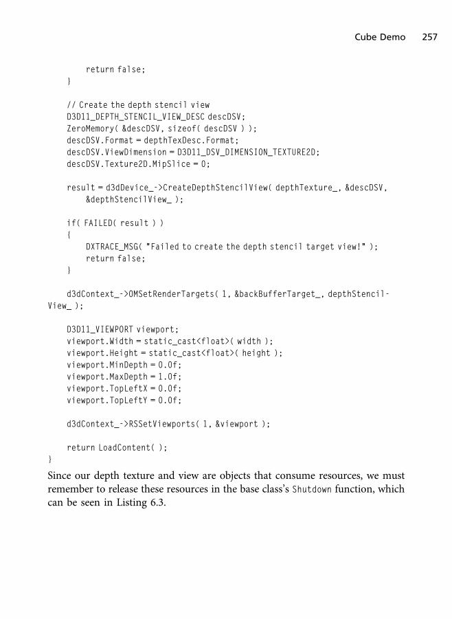
return false;}
// Create the depth stencil viewD3D11_DEPTH_STENCIL_VIEW_DESC descDSV;ZeroMemory( &descDSV, sizeof( descDSV ) );descDSV.Format = depthTexDesc.Format;descDSV.ViewDimension = D3D11_DSV_DIMENSION_TEXTURE2D;descDSV.Texture2D.MipSlice = 0;
result = d3dDevice_->CreateDepthStencilView( depthTexture_, &descDSV,&depthStencilView_ );
if( FAILED( result ) ){
DXTRACE_MSG( "Failed to create the depth stencil target view!" );return false;
}
d3dContext_->OMSetRenderTargets( 1, &backBufferTarget_, depthStencil-View_ );
D3D11_VIEWPORT viewport;viewport.Width = static_cast<float>( width );viewport.Height = static_cast<float>( height );viewport.MinDepth = 0.0f;viewport.MaxDepth = 1.0f;viewport.TopLeftX = 0.0f;viewport.TopLeftY = 0.0f;
d3dContext_->RSSetViewports( 1, &viewport );
return LoadContent( );}
Since our depth texture and view are objects that consume resources, we mustremember to release these resources in the base class’s Shutdown function, whichcan be seen in Listing 6.3.
Cube Demo 257

Listing 6.3 The updated Shutdown function.
void Dx11DemoBase::Shutdown( ){
UnloadContent( );
if( depthTexture_ ) depthTexture_->Release( );if( depthStencilView_ ) depthStencilView_->Release( );if( backBufferTarget_ ) backBufferTarget_->Release( );if( swapChain_ ) swapChain_->Release( );if( d3dContext_ ) d3dContext_->Release( );if( d3dDevice_ ) d3dDevice_->Release( );
depthTexture_ = 0;depthStencilView_ = 0;backBufferTarget_ = 0;swapChain_ = 0;d3dContext_ = 0;d3dDevice_ = 0;
}
Our demo class will be called CubeDemo. This CubeDemo class will create threeconstant buffers for the model, view, and projection matrices. Since our demosreally only need to combine these matrices into a model-view projection matrix,we’ll keep them separate to show an example of utilizing multiple constant buffers.Later in this section you’ll see how this relates to HLSL and setting usage trends.
Also in the demo we create an index buffer. In Chapter 3 we mentioned that anindex buffer is used to specify array indices into a vertex list to specify whichvertices form triangles. With large polygon count (closed volume) models thiscan save a lot of memory when representing our geometry. Knowing how tocreate an index buffer is important when it comes to 3D rendering, so we willcover this in this demo.
The CubeDemo can be seen in Listing 6.4. It builds off of the Texture Mappingdemo of Chapter 3. We are also storing the view and projection matrices on theclass level, since these never change in this specific demo and don’t need to berecalculated for each frame. In Chapter 8, when we talk about cameras, we willupdate the view matrix each frame in the Update function, and that camerademo will build directly off of this demo’s code.
258 Chapter 6 n 3D Primer
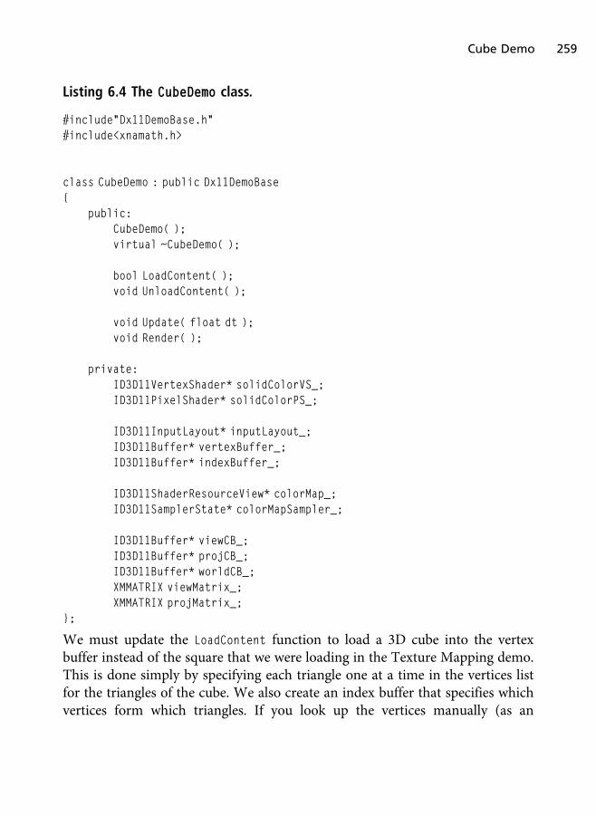
Listing 6.4 The CubeDemo class.
#include"Dx11DemoBase.h"#include<xnamath.h>
class CubeDemo : public Dx11DemoBase{
public:CubeDemo( );virtual ~CubeDemo( );
bool LoadContent( );void UnloadContent( );
void Update( float dt );void Render( );
private:ID3D11VertexShader* solidColorVS_;ID3D11PixelShader* solidColorPS_;
ID3D11InputLayout* inputLayout_;ID3D11Buffer* vertexBuffer_;ID3D11Buffer* indexBuffer_;
ID3D11ShaderResourceView* colorMap_;ID3D11SamplerState* colorMapSampler_;
ID3D11Buffer* viewCB_;ID3D11Buffer* projCB_;ID3D11Buffer* worldCB_;XMMATRIX viewMatrix_;XMMATRIX projMatrix_;
};
We must update the LoadContent function to load a 3D cube into the vertexbuffer instead of the square that we were loading in the Texture Mapping demo.This is done simply by specifying each triangle one at a time in the vertices listfor the triangles of the cube. We also create an index buffer that specifies whichvertices form which triangles. If you look up the vertices manually (as an
Cube Demo 259

exercise) using the array indices in the index buffer, then you can clearly see howeach triangle is specified.
Creating the index buffer is done the exact same way as the vertex buffer, withthe exception that we are using a bind flag of D3D11_BIND_INDEX_BUFFER. That’sit! At the end of the LoadContent function we create our three constant buffers,and we initialize our view and projection matrices. Since we don’t have a camerayet, the view matrix will equal an identity matrix (this will change in Chapter 8).The projection matrix is created as a perspective projection, which can be donewith a call to XMMatrixPerspectiveFovLH. The XMMatrixPerspectiveFovLH func-tion takes as parameters the field of view of the camera in radians, the aspectratio of the camera, and the near and far clip planes. If you wish to specify thefield of view in degrees, you’ll have to convert those degrees to radians yourselfbefore passing it as a parameter to this function. Also, the aspect ratio ismeasured as the width divided by the height.
The updated LoadContent function can be seen in Listing 6.5. The bulk of thecode deals with defining the triangle data manually. In Chapter 8 we will exploreloading models from files exported by tools such as 3D Studio Max, which isnecessary for complex and detailed models.
Listing 6.5 The updated LoadContent function.
bool CubeDemo::LoadContent( ){
// ... Previous demo’s LoadContent code ...
VertexPos vertices[] ={
{ XMFLOAT3( -1.0f, 1.0f, -1.0f ), XMFLOAT2( 0.0f, 0.0f ) },{ XMFLOAT3( 1.0f, 1.0f, -1.0f ), XMFLOAT2( 1.0f, 0.0f ) },{ XMFLOAT3( 1.0f, 1.0f, 1.0f ), XMFLOAT2( 1.0f, 1.0f ) },{ XMFLOAT3( -1.0f, 1.0f, 1.0f ), XMFLOAT2( 0.0f, 1.0f ) },
{ XMFLOAT3( -1.0f, -1.0f, -1.0f ), XMFLOAT2( 0.0f, 0.0f ) },{ XMFLOAT3( 1.0f, -1.0f, -1.0f ), XMFLOAT2( 1.0f, 0.0f ) },{ XMFLOAT3( 1.0f, -1.0f, 1.0f ), XMFLOAT2( 1.0f, 1.0f ) },{ XMFLOAT3( -1.0f, -1.0f, 1.0f ), XMFLOAT2( 0.0f, 1.0f ) },
260 Chapter 6 n 3D Primer

{ XMFLOAT3( -1.0f, -1.0f, 1.0f ), XMFLOAT2( 0.0f, 0.0f ) },{ XMFLOAT3( -1.0f, -1.0f, -1.0f ), XMFLOAT2( 1.0f, 0.0f ) },{ XMFLOAT3( -1.0f, 1.0f, -1.0f ), XMFLOAT2( 1.0f, 1.0f ) },{ XMFLOAT3( -1.0f, 1.0f, 1.0f ), XMFLOAT2( 0.0f, 1.0f ) },
{ XMFLOAT3( 1.0f, -1.0f, 1.0f ), XMFLOAT2( 0.0f, 0.0f ) },{ XMFLOAT3( 1.0f, -1.0f, -1.0f ), XMFLOAT2( 1.0f, 0.0f ) },{ XMFLOAT3( 1.0f, 1.0f, -1.0f ), XMFLOAT2( 1.0f, 1.0f ) },{ XMFLOAT3( 1.0f, 1.0f, 1.0f ), XMFLOAT2( 0.0f, 1.0f ) },
{ XMFLOAT3( -1.0f, -1.0f, -1.0f ), XMFLOAT2( 0.0f, 0.0f ) },{ XMFLOAT3( 1.0f, -1.0f, -1.0f ), XMFLOAT2( 1.0f, 0.0f ) },{ XMFLOAT3( 1.0f, 1.0f, -1.0f ), XMFLOAT2( 1.0f, 1.0f ) },{ XMFLOAT3( -1.0f, 1.0f, -1.0f ), XMFLOAT2( 0.0f, 1.0f ) },
{ XMFLOAT3( -1.0f, -1.0f, 1.0f ), XMFLOAT2( 0.0f, 0.0f ) },{ XMFLOAT3( 1.0f, -1.0f, 1.0f ), XMFLOAT2( 1.0f, 0.0f ) },{ XMFLOAT3( 1.0f, 1.0f, 1.0f ), XMFLOAT2( 1.0f, 1.0f ) },{ XMFLOAT3( -1.0f, 1.0f, 1.0f ), XMFLOAT2( 0.0f, 1.0f ) },
};
D3D11_BUFFER_DESC vertexDesc;ZeroMemory( &vertexDesc, sizeof( vertexDesc ) );vertexDesc.Usage = D3D11_USAGE_DEFAULT;vertexDesc.BindFlags = D3D11_BIND_VERTEX_BUFFER;vertexDesc.ByteWidth = sizeof( VertexPos ) * 24;
D3D11_SUBRESOURCE_DATA resourceData;ZeroMemory( &resourceData, sizeof( resourceData ) );resourceData.pSysMem = vertices;
d3dResult = d3dDevice_->CreateBuffer( &vertexDesc,&resourceData, &vertexBuffer_ );
if( FAILED( d3dResult ) ){
DXTRACE_MSG( "Failed to create vertex buffer!" );return false;
}
Cube Demo 261

WORD indices[] ={
3, 1, 0, 2, 1, 3,6, 4, 5, 7, 4, 6,11, 9, 8, 10, 9, 11,14, 12, 13, 15, 12, 14,19, 17, 16, 18, 17, 19,22, 20, 21, 23, 20, 22
};
D3D11_BUFFER_DESC indexDesc;ZeroMemory( &indexDesc, sizeof( indexDesc ) );indexDesc.Usage = D3D11_USAGE_DEFAULT;indexDesc.BindFlags = D3D11_BIND_INDEX_BUFFER;indexDesc.ByteWidth = sizeof( WORD ) * 36;indexDesc.CPUAccessFlags = 0;resourceData.pSysMem = indices;
d3dResult = d3dDevice_->CreateBuffer( &indexDesc,&resourceData, &indexBuffer_ );
if( FAILED( d3dResult ) ){
DXTRACE_MSG( "Failed to create index buffer!" );return false;
}
d3dResult = D3DX11CreateShaderResourceViewFromFile( d3dDevice_,"decal.dds", 0, 0, &colorMap_, 0 );
if( FAILED( d3dResult ) ){
DXTRACE_MSG( "Failed to load the texture image!" );return false;
}
D3D11_SAMPLER_DESC colorMapDesc;ZeroMemory( &colorMapDesc, sizeof( colorMapDesc ) );colorMapDesc.AddressU = D3D11_TEXTURE_ADDRESS_WRAP;colorMapDesc.AddressV = D3D11_TEXTURE_ADDRESS_WRAP;
262 Chapter 6 n 3D Primer
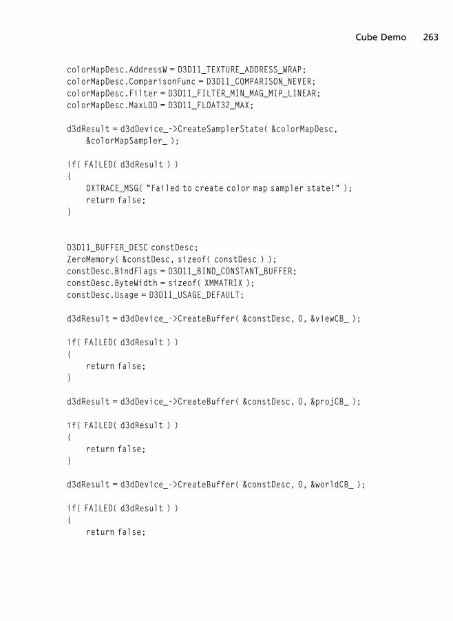
colorMapDesc.AddressW = D3D11_TEXTURE_ADDRESS_WRAP;colorMapDesc.ComparisonFunc = D3D11_COMPARISON_NEVER;colorMapDesc.Filter = D3D11_FILTER_MIN_MAG_MIP_LINEAR;colorMapDesc.MaxLOD = D3D11_FLOAT32_MAX;
d3dResult = d3dDevice_->CreateSamplerState( &colorMapDesc,&colorMapSampler_ );
if( FAILED( d3dResult ) ){
DXTRACE_MSG( "Failed to create color map sampler state!" );return false;
}
D3D11_BUFFER_DESC constDesc;ZeroMemory( &constDesc, sizeof( constDesc ) );constDesc.BindFlags = D3D11_BIND_CONSTANT_BUFFER;constDesc.ByteWidth = sizeof( XMMATRIX );constDesc.Usage = D3D11_USAGE_DEFAULT;
d3dResult = d3dDevice_->CreateBuffer( &constDesc, 0, &viewCB_ );
if( FAILED( d3dResult ) ){
return false;}
d3dResult = d3dDevice_->CreateBuffer( &constDesc, 0, &projCB_ );
if( FAILED( d3dResult ) ){
return false;}
d3dResult = d3dDevice_->CreateBuffer( &constDesc, 0, &worldCB_ );
if( FAILED( d3dResult ) ){
return false;
Cube Demo 263
}
viewMatrix_ = XMMatrixIdentity( );projMatrix_ = XMMatrixPerspectiveFovLH( XM_PIDIV4, 800.0f / 600.0f,
0.01f, 100.0f );
viewMatrix_ = XMMatrixTranspose(viewMatrix_ );projMatrix_ = XMMatrixTranspose( projMatrix_ );
return true;}
Remember that all of our new objects need to be released by the UnloadContent
function. This includes our three constant buffers and well as our newly createdindex buffer. This can be seen in Listing 6.6 in the updated UnloadContent
function.
Listing 6.6 The updated UnloadContent function.
void CubeDemo::UnloadContent( ){
if( colorMapSampler_ ) colorMapSampler_->Release( );if( colorMap_ ) colorMap_->Release( );if( solidColorVS_ ) solidColorVS_->Release( );if( solidColorPS_ ) solidColorPS_->Release( );if( inputLayout_ ) inputLayout_->Release( );if( vertexBuffer_ ) vertexBuffer_->Release( );if( indexBuffer_ ) indexBuffer_->Release( );if( viewCB_ ) viewCB_->Release( );if( projCB_ ) projCB_->Release( );if( worldCB_ ) worldCB_->Release( );
colorMapSampler_ = 0;colorMap_ = 0;solidColorVS_ = 0;solidColorPS_ = 0;inputLayout_ = 0;vertexBuffer_ = 0;indexBuffer_ = 0;viewCB_ = 0;
264 Chapter 6 n 3D Primer

projCB_ = 0;worldCB_ = 0;
}
The last code to cover is the HLSL shader and the rendering function. Therendering function adds a line of code to clear the depth buffer by calling thedevice context’s ClearDepthStencilView function, which takes as parametersthe depth/stencil view, what we are clearing (in this case we use the clear depthflag of D3D11_CLEAR_DEPTH), a value between 0 and 1 to clear the depth bufferto, and a value to clear the stencil buffer to.
Before we begin rendering, we must set the index buffer to the input assembler,since we are making use of it. This is done with a call to IASetIndexBuffer,which takes as parameters the index buffer, the data format of the buffer, and astarting offset in bytes. The format we used to create the index buffer is a 16-bitunsigned integer, which means we must use DXGI_FORMAT_R16_UINT for the dataformat parameter of this function. Whatever format you use for the index bufferarray must be passed to this function so that Direct3D knows how to properlyaccess the elements of the buffer.
The last steps we take are to bind our constant buffer and draw our geometry.We bind each constant buffer to b0, b1, and b2, which are specified in the HLSLshader file. To draw the data, we don’t use a call to the Draw function but insteadwe call the DrawIndexed function. DrawIndexed takes as parameters the numberof indices in the index buffer, the starting index we are drawing, and the basevertex location, which is an offset added to each index before reading from thevertex buffer. This can be useful when only drawing portions of the vertexbuffer, which can happen if you batched multiple models in one larger vertexbuffer. That is a topic for advanced rendering optimizations.
The updated rendering function can be seen in Listing 6.7.
Listing 6.7 The updated Render function.
void CubeDemo::Render( ){
if( d3dContext_ == 0 )return;
float clearColor[4] = { 0.0f, 0.0f, 0.25f, 1.0f };
Cube Demo 265
d3dContext_->ClearRenderTargetView( backBufferTarget_, clearColor );d3dContext_->ClearDepthStencilView( depthStencilView_,
D3D11_CLEAR_DEPTH, 1.0f, 0 );
unsigned int stride = sizeof( VertexPos );unsigned int offset = 0;
d3dContext_->IASetInputLayout( inputLayout_ );d3dContext_->IASetVertexBuffers( 0, 1, &vertexBuffer_, &stride, &offset );d3dContext_->IASetIndexBuffer( indexBuffer_, DXGI_FORMAT_R16_UINT, 0 );d3dContext_->IASetPrimitiveTopology(D3D11_PRIMITIVE_TOPOLOGY_TRIANGLE
LIST);
d3dContext_->VSSetShader( solidColorVS_, 0, 0 );d3dContext_->PSSetShader( solidColorPS_, 0, 0 );d3dContext_->PSSetShaderResources( 0, 1, &colorMap_ );d3dContext_->PSSetSamplers( 0, 1, &colorMapSampler_ );
XMMATRIX rotationMat = XMMatrixRotationRollPitchYaw( 0.0f, 0.7f, 0.7f );XMMATRIX translationMat = XMMatrixTranslation( 0.0f, 0.0f, 6.0f );
XMMATRIX worldMat = rotationMat * translationMat;worldMat = XMMatrixTranspose( worldMat );
d3dContext_->UpdateSubresource( worldCB_, 0, 0, &worldMat, 0, 0 );d3dContext_->UpdateSubresource( viewCB_, 0, 0, &viewMatrix_, 0, 0 );d3dContext_->UpdateSubresource( projCB_, 0, 0, &projMatrix_, 0, 0 );
d3dContext_->VSSetConstantBuffers( 0, 1, &worldCB_ );d3dContext_->VSSetConstantBuffers( 1, 1, &viewCB_ );d3dContext_->VSSetConstantBuffers( 2, 1, &projCB_ );
d3dContext_->DrawIndexed( 36, 0, 0 );
swapChain_->Present( 0, 0 );}
In the HLSL code we create three constant buffers that we register to b0, b1, andb2. We must keep in mind that the buffers must be consistent to what we’ve
266 Chapter 6 n 3D Primer
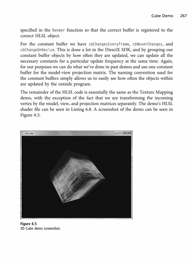
specified in the Render function so that the correct buffer is registered to thecorrect HLSL object.
For the constant buffer we have cbChangesEveryFrame, cbNeverChanges, andcbChangeOnResize. This is done a lot in the DirectX SDK, and by grouping ourconstant buffer objects by how often they are updated, we can update all thenecessary constants for a particular update frequency at the same time. Again,for our purposes we can do what we’ve done in past demos and use one constantbuffer for the model-view projection matrix. The naming convention used forthe constant buffers simply allows us to easily see how often the objects withinare updated by the outside program.
The remainder of the HLSL code is essentially the same as the Texture Mappingdemo, with the exception of the fact that we are transforming the incomingvertex by the model, view, and projection matrices separately. The demo’s HLSLshader file can be seen in Listing 6.8. A screenshot of the demo can be seen inFigure 6.5.
Figure 6.5
3D Cube demo screenshot.
Cube Demo 267

Listing 6.8 The HLSL shader for the CubeDemo.
Texture2D colorMap_ : register( t0 );SamplerState colorSampler_ : register( s0 );
cbuffer cbChangesEveryFrame : register( b0 ){
matrix worldMatrix;};
cbuffer cbNeverChanges : register( b1 ){
matrix viewMatrix;};
cbuffer cbChangeOnResize : register( b2 ){
matrix projMatrix;};
struct VS_Input{
float4 pos : POSITION;float2 tex0 : TEXCOORD0;
};
struct PS_Input{
float4 pos : SV_POSITION;float2 tex0 : TEXCOORD0;
};
PS_Input VS_Main( VS_Input vertex ){
PS_Input vsOut = ( PS_Input )0;vsOut.pos = mul( vertex.pos, worldMatrix );vsOut.pos = mul( vsOut.pos, viewMatrix );vsOut.pos = mul( vsOut.pos, projMatrix );
268 Chapter 6 n 3D Primer

vsOut.tex0 = vertex.tex0;
return vsOut;}
float4 PS_Main( PS_Input frag ) : SV_TARGET{
return colorMap_.Sample( colorSampler_, frag.tex0 );}
Additional XNA Math Topics
XNA Math has hundreds of functions and structures. There would be too muchto cover in just one chapter, and the math behind it could span multiple books. Inthe remainder of this chapter we will look at other areas of XNA Math that mightbe important to know for a user at the beginner level of working with DirectX 11.
Compiler Directives
XNA Math has a list of compiler directives used to tune how XNA Math iscompiled and used within an application. These compiler directives givedevelopers the ability to specify their applications’ functionality and includethe following:
n _XM_NO_INTRINSICS_
n _XM_SSE_INTRINSICS_
n _XM_VMX128_INTRINSICS_
n XM_NO_ALIGNMENT
n XM_NO_MISALIGNED_VECTOR_ACCESS
n XM_NO_OPERATOR_OVERLOADS
n XM_STRICT_VECTOR4
_XM_NO_INTRINSICS_ defines that no intrinsic types are to be used and that theXNA Math library will only use standard floating-point precision whenperforming its operations. This can be seen as the behavior that will allow anapplication to use XNA Math with no special optimizations or functionality.
Additional XNA Math Topics 269
_XM_SSE_INTRINSICS_ is used to enable the use of SSE and SSE2 intrinsic types onplatforms that support it. This define has no effect on platforms that do not supportSSE and SSE2. SSE and SSE2 are types of SIMD (single-instruction multiple data)operations that aim to boost performance by providing instruction-level parallelism,or in other words allow multiple operations to be done on multiple pieces of data atthe same time. SIMD is discussed in more detail later in this chapter under thesubsection “SIMD.” SSE stands for Streaming SIMD Extension.
_XM_VMX128_INTRINSICS_ is used to define that the Xbox 360 target use theVMX128 intrinsic but has no effect on other platforms. VMX is another SIMDset of instructions. VMX128 is an extension of the VMX set for use in Xenonprocessors, which is found inside the Xbox 360. Using this intrinsic should bedone if the game is being targeted toward the Xbox 360.
XM_NO_ALIGNMENT is used to define that no alignment should be made to the data.For example, the XMMATRIX type structure will not be aligned to 16 bytes usingthis directive. This is not defined by default since by default alignment takesplaces.
XM_NO_MISALIGNED_VECTOR_ACCESS is used to improve the performance of theVMX128 intrinsic when operating on write-combined memory. This affects theXbox 360’s Xenon processor.
XM_NO_OPERATOR_OVERLOADS is used to disable the use of Cþþ style operatoroverloads. By default this is not defined, but it can be used to force the omissionof overloaded operators.
XM_STRICT_VECTOR4 is used to determine if the X, Y, Z, and W components of theXMVECTOR and XMVECTORI types can be directly accessed (e.g., float� Val = vec.x).This only affects Xbox 360 targets that are defined using the __vector4 intrinsictype and has no effect on Windows targets using the __m128 type. Accessorfunctions can be used to access members of these structures when this strictdirective is used.
Constants
Compiler constants provide useful information to developers using the XNAMath library. The list of constants and what each one represents can be seen inthe following:
270 Chapter 6 n 3D Primer

n XNAMATH_VERSION—Used to obtain the XNA Math library version.
n XM_CACHE_LINE_SIZE—The size in bytes of the cache line used by streamoperations within the XNA Math library.
n XM_PI—Represents the value of PI.
n XM_2PI—Represents the value of 2�PI.
n XM_1DIVPI—Represents the value of 1 / PI.
n XM_1DIV2PI—Represents the value of 2 / PI.
n XM_PIDIV2—Represents the value of PI / 2.
n XM_PIDIV4—Represents the value of PI / 4.
n XM_PERMUTE_0X—This is a constant used to create a control vector thatcontrols how data is copied using the XMVectorPermute function. For thisconstant the first vector’s X component is copied to the resultvector’s location dictated by the control vector.
n XM_PERMUTE_0Y—This is a constant used to create a control vector thatcontrols how data is copied using the XMVectorPermute function. For thisconstant the first vector’s Y component is copied to the resultvector’s location dictated by the control vector.
n XM_PERMUTE_0Z—This is a constant used to create a control vector thatcontrols how data is copied using the XMVectorPermute function. For thisconstant the first vector’s Z component is copied to the resultvector’s location dictated by the control vector.
n XM_PERMUTE_0W—This is a constant used to create a control vector thatcontrols how data is copied using the XMVectorPermute function. For thisconstant the first vector’s W component is copied to the resultvector’s location dictated by the control vector.
n XM_PERMUTE_1X—This is a constant used to create a control vector thatcontrols how data is copied using the XMVectorPermute function. For thisconstant the second vector’s X component is copied to the result vector’slocation dictated by the control vector.
n XM_PERMUTE_1Y—This is a constant used to create a control vector thatcontrols how data is copied using the XMVectorPermute function. For this
Additional XNA Math Topics 271

constant the second vector’s Y component is copied to the result vector’slocation dictated by the control vector.
n XM_PERMUTE_1Z—This is a constant used to create a control vector thatcontrols how data is copied using the XMVectorPermute function. For thisconstant the second vector’s Z component is copied to the result vector’slocation dictated by the control vector.
n XM_PERMUTE_1W—This is a constant used to create a control vector thatcontrols how data is copied using the XMVectorPermute function. For thisconstant the second vector’s W component is copied to the result vec-tor’s location dictated by the control vector.
n XM_SELECT_0—Used to construct a control vector that controls how com-ponents are copied when using XMVectorSelect. The first vector’s compo-nent is copied to the index location in the result vector that is specifiedby the control vector.
n XM_SELECT_1—Used to construct a control vector that controls how com-ponents are copied when using XMVectorSelect. The second vector’scomponent is copied to the index location in the result vector that isspecified by the control vector.
n XM_CRMASK_CR6—A mask used to obtain a comparison result.
n XM_CRMASK_CR6TRUE—A mask used to obtain a comparison result andindicate if it is logically true.
n XM_CRMASK_CR6FALSE—A mask used to obtain a comparison result andindicate if it is logically false.
n XM_CRMASK_CR6BOUNDS—A mask used to obtain a comparison result andto verify if the results indicate some of the inputs were out of bounds.
Macros
Macros are available in XNA Math to provide extra functionality for commonoperations such as comparison operations, min and max determination, asserts,and the ability to mark objects as global. The complete list of XNA Math macrosis seen in the following:
272 Chapter 6 n 3D Primer

n XMASSERT
n XMGLOBALCONST
n XMComparisonAllFalse
n XMComparisonAllTrue
n XMComparisonAllInBounds
n XMComparisonAnyFalse
n XMComparisonAnyOutOfBounds
n XMComparisonAnyTrue
n XMComparisonMixed
n XMMax
n XMMin
XMASSERT provides debugging information by using assertions that are raisedwhen a condition is false. This macro takes the expression to test and willinclude the file and line information for you.
XMGLOBALCONST is used to specify an object as a “pick-any” global constant andis used to reduce the size of the data segment and avoid reloads of globalconstants that are used and declared in multiple places within the XNA Mathlibrary.
XMComparisonAllFalse is used to compare all components and to return true ifthey all evaluate to false.
XMComparisonAllTrue is used to compare all components and to return true ifthey all evaluate to true.
XMComparisonAllInBounds is used to test if all components are within the allowedbounds. True is returned if they are all within the bounds.
XMComparisonAnyFalse returns true if any, not necessarily all, of the componentsevaluate to false.
XMComparisonAnyOutOfBounds returns true if any, not necessarily all, of thecomponents are out of bounds.
Additional XNA Math Topics 273
XMComparisonAnyTrue returns true if any component, not necessarily all, eval-uates to true.
XMComparisonMixed returns true if some of the components evaluated to truewhile others evaluated to false.
XMMax compares two types and returns the one determined to be larger using theoperator <.
XMMin compares two types and returns the one determined to be smaller usingthe operator <.
Structures and Types
The goal of these various structures and types is to encapsulate their function-ality to make them easier to code with, easier to obtain portability, and allows fordata optimizations. All of these structures and types are exposed via the headerfile xnamath.h. So far we’ve briefly touched upon a few vector and matrixstructures, but in this section we will look at all of them.
The first sets of structures we will look at are the following:
n XMBYTE4
n XMBYTEN4
n XMCOLOR
n XMDEC4
n XMDECN4
n XMDHEN3
n XMDHENN3
The XMBYTE4 structure is used to create a four-component vector where eachcomponent is 1 byte (using the char data type). The XMBYTEN4 is similar to theXMBYTE4 structure with the exception that XMBYTEN4 is used to store normalizedinput. When XMBYTEN4 is initialized, its inputs are multiplied by 127.0f and scaledto fit the range 0.0 – 1.0f. Input data are to be in the range of -127.0f and 127.0fwhen using XMBYTEN4.
274 Chapter 6 n 3D Primer

XMCOLOR is a 32-bit color structure that stores red, blue, green, and alpha colorchannels. Each channel is an unsigned 8-bit value, where all four 8-bit channelstotal 32 bits for the entire structure. This is the same as XMBYTE4.
The XMDEC4 structure uses 10 bits for the X, Y, and Z components and uses 2 bitsfor the W. This totals 32 bits for the structure. XMDECN4 stores normalized values.On the other hand, XMDHEN3 stores 10 bits for the X component and stores 11 bitsfor the Y and Z components. XMDHENN3 stores the normalized values of a XMDHEN3.These can be used if you need structures that provide more bits per componentwhile totaling 32 bits in all.
The next set of structures deals with 2D components:
n XMFLOAT2
n XMFLOAT2A
n XMHALF2
n XMSHORT2
n XMSHORTN2
n XMUSHORT2
n XMUSHORTN2
XMFLOAT2 was mentioned earlier in this chapter and is used to represent a 2Dfloating-point vector. XMFLOAT2A represents a 16-byte boundary alignedXMFLOAT2.
XMHALF2 is a 2D vector used to store half-precision 16-bit floating-pointcomponents (instead of 32 bits per component), whereas XMSHORT2 is a 2Dvector storing half-precision 16-bit integer components. The U after XM for thesestructures are used to specify that they are unsigned, and the N that follows thenumber of components at the end of the names represents that they storenormalized values. Therefore the appearance of a U and N represents an unsignednormalized structure.
The next list displays all structures that are based on three components:
n XMFLOAT3
n XMFLOAT3A
Additional XNA Math Topics 275

n XMFLOAT3PK
n XMFLOAT3SE
n XMHEND3
n XMHENDN3
n XMDHEN3
n XMDHENN3
n XMU555
n XMU565
n XMUDHEN3
n XMUDHENN3
n XMUHEND3
n XMUHENDN3
XMFLOAT3, which was mentioned in the “Vectors” section earlier in this chapter,is a three-component structure of floating-point values. XMFLOAT3A is used for16-byte aligned three-component vectors. XMFLOAT3PK is used for three-component vectors, where the X and Y components are 10 bits each, andthe Z is 11 bits, whereas XMFLOAT3SE is a vector where the components use ninebits for the mantissa and five bits for the exponent.
XMDHEN3 (and its normalized form XMDHENN3) are 3D integer vectors with 10 bits forthe X components and 11 bits for the Y and Z. The XMHEND3 and XMHENDN3 are usedto store 11 bits for the X and Y and 10 bits for the Z components. The unsignedversions of these are XMUDHEN3 and XMUDHENN3.
The XMU555 is used to create a three-component vector that uses five bits for eachcomponent. The XMU565 creates a three-component vector that uses five bits forthe X and Z components but uses six bits for the Y.
The next list displays the 4D vector structures in the XNA Math library:
n XMFLOAT4
n XMFLOAT4A
n XMHALF4
276 Chapter 6 n 3D Primer
n XMICO4
n XMICON4
n XMSHORT4
n XMSHORTN4
n XMUBYTE4
n XMUBYTEN4
n XMUDEC4
n XMUDECN4
n XMUICO4
n XMUICON4
n XMUNIBBLE4
n XMUSHORT4
n XMUSHORTN4
n XMXDEC4
n XMXDECN4
n XMXICO4
n XMXICON4
XMFLOAT4 is a four-component floating-point vector that was mentioned in the“Vectors” section of this chapter. XMHALF4 is a half-precision 4D vector, andXMSHORT4 is half-precision using short integers. Again, the A that follows thestructure names is for byte-aligned structures, while N is for normalized versionsof them.
XMUBYTE4 is for a four-component unsigned byte (char) structure, and XMUNIB-
BLE4 uses four 4-bit integer components. The structures with ICO in their namesuse 20 bits for the X, Y, and Z components while using four bits for the W,which totals 64 bits for the ICO structures. The structures with DEC in theirnames use 10 bits for the X, Y, and Z components and two bits for the W, whichtotals 32 bits for the DEC structures. The XICO and XDEC structures use signedvalues, whereas UICO and UDEC use unsigned values.
Additional XNA Math Topics 277

The next list of structures is related to matrices:
n XMFLOAT3x3
n XMFLOAT4x3
n XMFLOAT4x3A
n XMFLOAT4x4
n XMFLOAT4x4A
n XMMATRIX
XMFLOAT3x3 represents a 3� 3 matrix of floating-point values (9 in total) and isusually used to represent rotation matrices. XMFLOAT4x3 represents 4� 3 matrices(12 elements in total), and XMFLOAT4x4 represents 4� 4 matrices (16 elements intotal). The A that follows the structure names indicates that they are alignedstructures. XMMATRIX is a row-major 4� 4 byte-aligned matrix that maps to fourvector hardware registers.
The final list that we’ll look at includes the additional types available using XNAMath. These additional types are listed as follows:
n HALF
n XMVECTOR
n XMVECTORF32
n XMVECTORI32
n XMVECTORU32
n XMVECTORU8
The HALF data type, which is aliased by USHORT, is a 16-bit floating-point number.It uses five bits for the exponent and 10 for the mantissa and has a sign bit.
The XMVECTOR structure is a four-component structure where each component isrepresented by 32 bits. This structure can use floating-point numbers or integersand is also optimally aligned and mapped to a hardware vector register.XMVECTOR was discussed in the “Vectors” section of this chapter.
The XMVECTORF32 is a portable 32-bit floating-point structure used by Cþþ
initializer syntax to initialize a XMVECTOR structure to use floating-point values.
278 Chapter 6 n 3D Primer
The XMVECTORI32 is a portable 32-bit integer structure used by Cþþ initializersyntax to initialize a XMVECTOR structure to use integer values.
The XMVECTORU32 is a portable structure used by Cþþ initializer syntax toinitialize a XMVECTOR structure to use unsigned integer values (UINT).
The XMVECTORI32 is a portable 8-bit structure used by Cþþ initializer syntax toinitialize a XMVECTOR structure to use byte values (char).
Additional Functions
In this section we will briefly discuss the additional functions availablethrough XNA Math that we have yet to touch upon. These functions dealwith colors, conversions, and scalars. The first type we’ll discuss is the colorfunctions.
Color Functions
XNA Math has several functions useful for performing color manipulation ondata. The first is used to adjust the contrast of a single color and is calledXMColorAdjustContrast, whose prototype can be seen as follows:
XMVECTOR XMColorAdjustContrast( XMVECTOR C, FLOAT Contrast );
The first parameter of the XMColorAdjustContrast function is an XMVECTOR thatrepresents a color value, where each component is to be in the range of 0.0 to1.0f. If the contrast is 0.0f, then the color is adjusted by 50% gray; if the contrastis 1.0f, then the full color is returned. Anything between the two extremes willreturn a contrasted color.
The next function is called XMColorAdjustSaturation, and it is used to adjust thesaturation of a color value. Its prototype is:
XMVECTOR XMColorAdjustSaturation( XMVECTOR C, FLOAT Saturation );
The first parameter of the function XMColorAdjustSaturation is also a XMVECTOR
that represents a color value, where each component is to be in the range of 0.0to 1.0f. If the saturation is 0.0f, then a gray color is returned; if the saturation is1.0f, then the full color is returned. Anything between 0.0 and 1.0 for thesaturation will return a value that linearly interpolates between the two (i.e., grayand the original color).
Additional XNA Math Topics 279

The next six functions are comparison functions. These functions include testingif two vectors are equal, not equal, greater than, less than, greater than or equalto, or less than or equal to. The functions test the first parameter with the secondand return a true/false result. Each of the comparison functions can be seen asfollows:
BOOL XMColorEqual( XMVECTOR C1, XMVECTOR C2 );BOOL XMColorNotEqual( XMVECTOR C1, XMVECTOR C2 );
BOOL XMColorGreater( XMVECTOR C1, XMVECTOR C2 );BOOL XMColorGreaterOrEqual( XMVECTOR C1, XMVECTOR C2 );
BOOL XMColorLess( XMVECTOR C1, XMVECTOR C2 );BOOL XMColorLessOrEqual( XMVECTOR C1, XMVECTOR C2 );
Another two functions that deal with comparison are XMColorIsInfinite, whichtests if a color is equal to infinity, and XMColorIsNaN which looks to see if one ofthe components is defined as NaN (not a number).
BOOL XMColorIsInfinite( XMVECTOR C );BOOL XMColorIsNaN( XMVECTOR C );
The next function is called XMColorModulate, and it is used to blend two colorstogether. The last color function is XMColorNegative, which is used to negate acolor. The function prototypes for these last two color functions are:
XMVECTOR XMColorModulate( XMVECTOR C1, XMVECTOR C2 );XMVECTOR XMColorNegative( XMVECTOR C );
The XMColorNegative function is similar to performing the following:
XMVECTOR col, result;
result.x = 1.0f - col.x;result.y = 1.0f - col.y;result.z = 1.0f - col.z;result.w = 1.0f - col.w;
A black color component would become white using XMColorNegative, whilewhite would become black. The same goes for intensities between 0.0 and 1.0,where their intensity of light and dark will be swapped.
280 Chapter 6 n 3D Primer

Conversion Functions
The conversion set of XNA Math functions is used to convert values from onetype to another. The XMConvertFloatToHalf function, the prototype of which canbe seen below, converts a 32-bit floating-point value to a HALF (half-precision).All floating-point exceptions such as NaN, negative and positive infinity, etc., areconverted to the value of 0x7FFF.
HALF XMConvertFloatToHalf( FLOAT Value );
To convert a HALF back to a floating-point value, we could use the followingfunction:
FLOAT XMConvertHalfToFloat( HALF Value );
Values passed to XMConvertHalfToFloat that equal 0x7FFF are converted to131008.0f, according to the XNA Math documentation.
If an array of values needs to be converted, we can use the XMConvertFloatTo-
HalfStream and XMConvertHalfToFloatStream. These functions take as parame-ters the address of the first value in the output stream array, the stride in bytesbetween each output value, the address of the first element in the input array, thestride in bytes between each input value, and the total number of elements weare converting. Both of these functions also return the first address of the outputstream, and their prototypes can be seen as follows:
HALF* XMConvertFloatToHalfStream( HALF* pOutputStream, UINT OutputStride,CONST FLOAT* pInputStream, UINT InputStride, UINT FloatCount );
FLOAT* XMConvertHalfToFloatStream( FLOAT *pOutputStream, UINT OutputStride,CONST HALF* pInputStream, UINT InputStride, UINT HalfCount );
Another set of useful functions is those dedicated to converting degrees toradians and vice-versa. In games we often use one or the other, and sometimes itmight be convenient to take one representation and adopt it to another. Thefunctions to perform this conversion are XMConvertToDegrees and XMConvert-
ToRadians, both of which take a floating-point value as a parameter and returnthe result as a floating-point value. Their prototypes are the following:
FLOAT XMConvertToDegrees( FLOAT fRadians );FLOAT XMConvertToRadians( FLOAT fDegrees );
The last conversion functions are used to convert a float vector to an integer vectorand vice-versa while performing a uniform bias. XMConvertVectorIntToFloat and
Additional XNA Math Topics 281
XMConvertVectorUIntToFloat will perform the conversion of the first parameterand divide the results by the two raised to the DivExponent power. XMConvertVec-torFloatToInt and XMConvertVectorFloatToUInt will do something similar butwill multiply the two to the MulExponent power. Their prototypes can be seen asfollows:
XMVECTOR XMConvertVectorFloatToInt( XMVECTOR VFloat, UINT MulExponent );XMVECTOR XMConvertVectorFloatToUInt( XMVECTOR VFloat, UINT MulExponent );
XMVECTOR XMConvertVectorIntToFloat( XMVECTOR VInt, UINT DivExponent );XMVECTOR XMConvertVectorUIntToFloat( XMVECTOR VUInt, UINT DivExponent );
Scalar Functions
Next are the scalar functions. These functions take floating-point values andperform a specific operation on them. There are functions for calculating thecosine of a value, such as XMScalarCos, functions for calculating the sine of avalue, such as XMScalarSin, functions to calculate the arccosine (XMScalarACos)and arcsine (XMScalarASin), and functions to calculate the estimation of thesevalues. The function prototypes of these functions are as follows:
FLOAT XMScalarCos( FLOAT Value );FLOAT XMScalarCosEst( FLOAT Value );
FLOAT XMScalarSin( FLOAT Value );FLOAT XMScalarSinEst( FLOAT Value );
FLOAT XMScalarACos( FLOAT Value );FLOAT XMScalarACosEst( FLOAT Value );
FLOAT XMScalarASin( FLOAT Value );FLOAT XMScalarASinEst( FLOAT Value );
FLOAT XMScalarSinCos( FLOAT Value );FLOAT XMScalarSinCosEst( FLOAT Value );
In addition to the trigonometry functions, we also have XMScalarModAngle andXMScalarNearEqual. XMScalarModAngle will compute an angle between –PI andþPI that is congruent to Value modulo 2PI. XMScalarNearEqual will test twovalues to see if they are close to being equal. Both function prototypes can beseen as follows:
282 Chapter 6 n 3D Primer

FLOAT XMScalarModAngle( FLOAT Value );BOOL XMScalarNearEqual( FLOAT S1, FLOAT S2, FLOAT Epsilon )
Additional Math Structures and Topics
XNA Math has support for colors, vectors, matrices, planes, and quaternions. Allof these can be represented using 4D vectors, where a 4� 4 matrix is fourvectors representing each row. Planes and quaternions touch upon moreadvanced concepts that we won’t get to explore in this book, but XNA Mathhas functions to work with them.
A plane can be represented using a 4D vector. A plane is an infinitely smallsurface that extends along two axes infinitely. A plane is defined simply as anormal vector that specifies the direction the plane is facing (X, Y, and Z) and adistance value (stored in W) that represents how far from the origin this plane is.
Planes are commonly used for culling and collision detection, trigger volumes,and other concepts along those lines. We do not render planes like we dotriangles, points, and lines.
Unit quaternions can be used to represent rotations and orientations. Aquaternion has four floating-point members, so therefore a 4D vector such asXMFLOAT4 or XMVECTOR can be used as a quaternion.
Game Physics and Collision Detection
Everything in this chapter is related not only to graphics but also to gamephysics. Physics is a huge part of 3D game development and cannot be avoidedwhen creating realistic simulations. Physics in games usually deals with pointmasses, rigid bodies, and soft bodies.
Point masses are physics objects that have their linear velocities and positionsupdated but have no applied rotations. These are often the easiest to start withfor beginners and are common for many simulations in games, includingparticle systems.
Rigid bodies are often used for objects in the scene that can have forces actingupon them that causes them to not only have forces applied to their position andvelocity but also their angular movements. This is used for things like crates andother objects as they react to explosions and other forces that cause them to
Additional Math Structures and Topics 283

realistically move throughout the scene by moving and rotating as they interactwith the world. Another example can be seen with rag-doll bodies, whereenemies can fall down a flight of stairs realistically as they collide with theenvironment. Rigid bodies do not deform in shape.
Soft bodies are not used as often as the other two but are used to simulate objectsthat can deform in shape. Epic’s Unreal game engine has support for soft bodies.
Collision detection and response is the act of detecting when one or moreobjects collide and resolving those collisions by applying forces on them orrestricting their movements. This is done so that objects never penetrate oneanother and so that they react as you would expect them to when they touch.Physics in games is applying forces on objects so that they behave as designedwithin the environment. Collision detection allows us to catch objects that startto penetrate each other as a result of these forces acting upon them, and theresponse to collision allows us to deal with that collision realistically to addfurther to the simulation. Although they can go hand in hand, physics andcollision detection are separate subjects that meet to create the completesimulation the designers intended.
Summary
Math is an important topic in video game development. XNA Math, which ispart of the DirectX 11 SDK, is a huge library of optimized code that we have atour disposal. In this chapter we mainly covered the topics in XNA Math thatwere important for this book, but the library itself is made up of hundreds ofstructures and functions. It is a huge library and is definitely a very useful tool tohave at our disposal. When it is used properly, you can obtain great performanceusing XNA Math.
What You Have Learned
n Learned about vectors
n Learned about matrices
n Learned about coordinate systems and transformations
284 Chapter 6 n 3D Primer
n Learned about the various functions and structures available throughXNA Math
n Learned about projections
Chapter Questions
You can find the answers to the chapter review questions in Appendix A on thisbook’s companion website.
1. Define a vector.
2. Define a matrix.
3. What is the difference between XMVECTOR and XMFLOAT4?
4. What is the difference between XMFLOAT4 and XMFLOAT4A?
5. How is a point defined in a 3D coordinate system?
6. What does normalizing a vector do?
7. What is the purpose of the dot product calculation?
8. What primitive type consists of a series of connected lines?
9. What is the identity matrix?
10. What is another term for multiplying matrices?
Chapter Questions 285

This page intentionally left blank
Shaders and Effects
Shaders have been a part of Direct3D for a while now. Vertex and pixel shadershave given developers the power to control every detail of how their data ismanipulated in multiple stages of the pipeline, giving them increased realism.Now with Direct3D 11, the next iteration of shader technology is being released:shader model 5.0.
In this chapter:
n What an effect file is
n How to use the High Level Shading Language
n What the various types of shaders are
n A basic understanding of lighting
n HLSL reference
Shaders in Direct3D
The capabilities of both vertex and pixel shaders have been increased. Thenumber of instructions possible has gone up, more textures can be accessed, andshaders can be more complicated. Instead of just limiting the improvements tothe previous shader types, Direct3D 11 introduces compute shaders and hull anddomain shaders. These new shaders are accompanied by Direct3D 10’s intro-duction to geometry shaders and vertex and pixel shaders, which have beenaround since DirectX 8.
Chapter 7
287

History of Programmable Shaders
Graphics programming before shaders used a set of fixed algorithms thatcollectively was known as the fixed function pipeline. To enable various featuresand effects, the fixed function pipeline essentially served as a way to enable anddisable built-in states. This was very limiting to developers because what couldbe done in graphics APIs such as Direct3D and OpenGL was fixed by those incontrol of the API and was not expandable.
In DirectX 8, the graphics pipeline in Direct3D first offered programmableshaders, along with the fixed function algorithms. The graphics pipeline wasprogrammable via assembly instructions or HLSL, the High Level ShadingLanguage. In Direct3D 10, HLSL became the only way to write programmableshaders, and not even assembly instructions are supported. Also in Direct3D 10,the graphics pipeline became 100% programmable, and the fixed functionpipeline was completely removed.
Because Direct3D no longer supports the fixed function pipeline, it falls to youto designate the behavior of how vertices and pixels are handled. The fixedfunction pipeline previously had a set way of processing vertices as they passedthrough on their way to being drawn. This restricted the options you had to fullycontrol the pipeline, limiting you to the functionality the pipeline supported.There was a single method for handling lighting and a set maximum value oftextures you could work with. This severely limited the effects you could achieveusing Direct3D.
Today, as each vertex is processed by the system, you get the opportunity tomanipulate it or to allow it to pass through unchanged. The same can be said forpixels. Any pixel being rendered by the system also is provided to you to bechanged before going to the screen. The functionality to change vertices andpixels is contained within Direct3D’s shader mechanism.
Shaders are Direct3D’s way of exposing pieces of the pipeline to be dynamicallyreprogrammed by you. Direct3D supports several types of shaders: vertex, pixel,geometry, compute, hull, and domain.
Vertex shaders operate on just what you’d expect: vertices. Every vertex goingthrough the pipeline is made available to the current vertex shader before beingoutput. Likewise, any pixel being rendered must also pass through the pixel
288 Chapter 7 n Shaders and Effects

shaders. Geometry shaders are a special type of shader introduced with Direct3D10. Geometry shaders allow for multiple vertices to be manipulated simulta-neously, giving the option of controlling entire primitives of geometry.
One of the new shader types in Direct3D 11 is compute shaders. A computeshader, which requires at least hardware that supports shader model 4.0, is usedto perform general parallel computing on graphics units. Compute shaders canbe used for anything from graphics to physics, video encoding and decoding, etc.Not all tasks are suitable to be executed by a GPU because of the GPU’s design,but those tasks that do fit the architecture can see an increase in performance bytaking advantage of the additional processing power.
The two other types of shaders new to Direct3D 11 are hull and domain shaders,as well as bringing an additional stage known as the tessellator. The tessellatingstage is not programmable, but the shaders that accompany it (hull and domain)are. The hull shader basically is used to transform incoming surface data as it runson the source control mesh’s control points, whereas the domain shader executesfor each generated vertex. The idea of tessellation is to take a control meshdefined by surface (not triangle lists as we have done throughout this book) and asubdivide it dynamically to generate a mesh of varying levels of detail. Ideally thismeans that we can generate very high polygonal models within the graphicshardware without actually having to send that detail to the graphics hardware.Think of it as dynamic level of detail for advanced graphics programming.
Effect Files
In Direct3D there are what are known as effect files. Shaders created via thesefiles are bundled together in what’s called an effect. Most of the time, you’ll beusing a combination of vertex and pixel shaders together to create a certainbehavior, called a technique. A technique defines a rendering effect, and an effectfile can have multiple rendering techniques within.
While using shaders individually is still possible with Direct3D 11, you’ll findthem extremely useful when grouped together into an effect. An effect is asimple way of packaging the needed shaders together to render objects in aparticular way. The effect is loaded as a single object, and the included shadersare executed when necessary. By changing the effect you’re applying to yourscene, you easily change the method Direct3D is using to do the rendering.
Effect Files 289
Effects are defined with an effect file, a text format that is loaded in from disk,compiled, and executed.
Although you can use effect files in Direct3D, they are not necessary. All demosthroughout this book loaded the code for the individual shaders one at a time.The difference between effect files and what we have been doing so far is thateffect files have additional information other than just the shaders themselves,such as rendering states, blend states, etc.
Effect File Layout
Effect files are a way of containing a particular set of rendering functionality.Each effect, applied when drawing objects in your scene, dictates what theobjects look like and how they’re drawn. For example, you may create an effectwhose job it is to texture objects, or you may create an effect to generate lightingbloom or blur. You could also have different versions of these effects within aneffect file, which could be useful if you had to target lower-end machines but alsooffer an alternative to an effect designed for high-end machines. Effects have anamazing versatility in how they can be used.
Previously, vertex and pixel shaders were loaded and applied separately. Effectscombine the shaders into a self-contained unit that encompasses functionality ofmultiple shader types.
Effects are comprised of a couple of different sections:
n External variables—Variables that get their data from the calling pro-gram.
n Input structures—Structures that define the information being passedbetween shaders.
n Shaders—Shader’s code (an effect file can have many shaders within).
n Technique block(s)—Defines the shaders and passes available within theeffect.
The simplest form of effect contains a technique with a vertex shader that allowsthe incoming data from the vertex structure to just pass through. This means thevertex position and other properties will not be changed in any way and arepassed on to the next stage in the pipeline.
290 Chapter 7 n Shaders and Effects
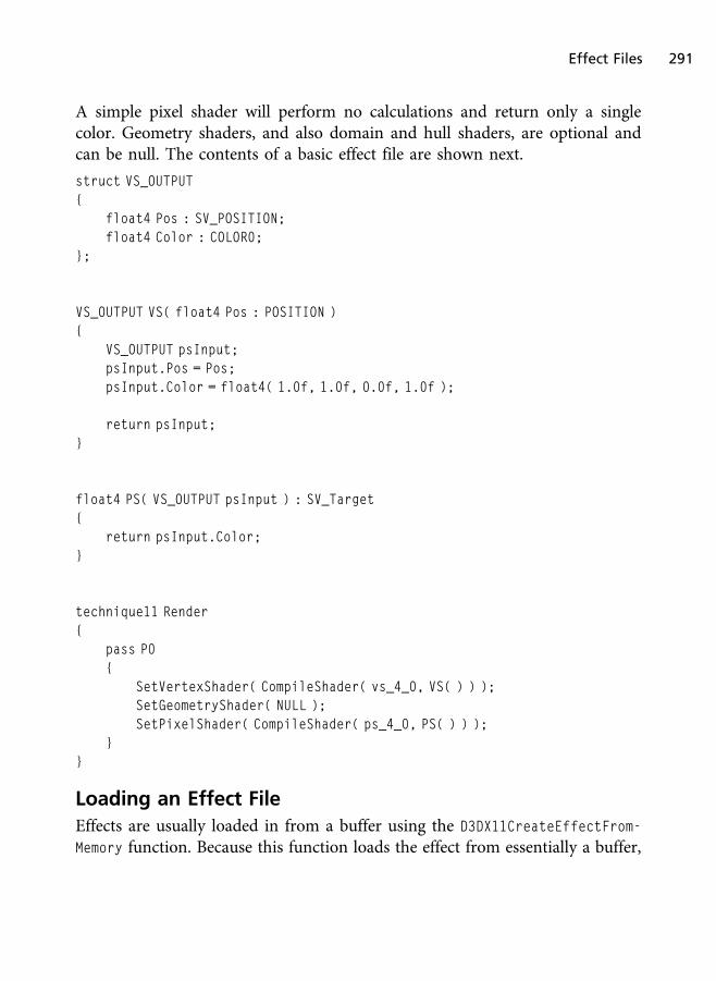
A simple pixel shader will perform no calculations and return only a singlecolor. Geometry shaders, and also domain and hull shaders, are optional andcan be null. The contents of a basic effect file are shown next.
struct VS_OUTPUT{
float4 Pos : SV_POSITION;float4 Color : COLOR0;
};
VS_OUTPUT VS( float4 Pos : POSITION ){
VS_OUTPUT psInput;psInput.Pos = Pos;psInput.Color = float4( 1.0f, 1.0f, 0.0f, 1.0f );
return psInput;}
float4 PS( VS_OUTPUT psInput ) : SV_Target{
return psInput.Color;}
technique11 Render{
pass P0{
SetVertexShader( CompileShader( vs_4_0, VS( ) ) );SetGeometryShader( NULL );SetPixelShader( CompileShader( ps_4_0, PS( ) ) );
}}
Loading an Effect File
Effects are usually loaded in from a buffer using the D3DX11CreateEffectFrom-
Memory function. Because this function loads the effect from essentially a buffer,
Effect Files 291

you can read an effect off a file using std::ifstream and pass along the file’scontents to this function. D3DX11CreateEffectFromMemory has the followingfunction prototype:
HRESULT D3DX11CreateEffectFromMemory(void* pData,SIZE_T DataLength,UINT FXFlags,ID3D11Device* pDevice,ID3DX11Effect** ppEffect
);
The parameters for the D3DX11CreateEffectFromMemory starts with the data ofthe effect file (the HLSL effect source code). The parameters that follow thesource include the size of the source code in bytes, compilation flags, theDirect3D 11 device, and a pointer to an ID3DX11Effect object that will hold theeffect.
External Variables and Constant Buffers
Most effects will need additional input past just the list of vertices; this is whereexternal variables are useful. External variables are those variables declaredwithin your effects that are visible from within your application code. Variablesthat receive information like current frame time, world projection, or lightpositions can be declared within the effect, so they can be updated from thecalling program.
With the introduction of Direct3D 10, all external variables now reside inconstant buffers. Constant buffers are used to group variables visible to thecalling program so that they can be optimized for access. Constant buffers aresimilar in definition to structures and are created using the cbuffer keyword. Anexample can be seen in the following HLSL code snippet:
cbuffer Variables{
matrix Projection;};
Constant buffers are commonly declared at the top of an effect file and resideoutside of any other section. For ease of use, it can be useful to group togethervariables based on the amount they are accessed. For instance, variables that
292 Chapter 7 n Shaders and Effects

get an initial value would be grouped separately from variables that are updatedon a frame by frame basis. You have the ability to create multiple constantbuffers.
When the effect file is loaded, you can bind the external variables to the effectvariables within your application. The following code shows how the externalvariable “Projection” is bound to the ID3DX11EffectMatrixVariable in theapplication.
ID3DX11EffectMatrixVariable * projMatrixVar = 0;
projMatrixVar = pEffect->GetVariableByName( "Projection" )->AsMatrix( );projMatrixVar->SetMatrix( ( float* )&finalMatrix );
Input and Output Structures
Effect files consistently need to pass multiple values between shaders; to keepthings simple, the variables are passed within a structure. The structure allowsfor more than one variable to be bundled together into an easy-to-send packageand helps to minimize the work needed when adding a new variable.
For instance, vertex shaders commonly need to pass values like vertex position,color, or normal value along to the pixel shader. Since the vertex shader has thelimitation of a single return value, it simply packages the needed variables intothe structure and sends it to the pixel shader. The pixel shader then accesses thevariables within the structure. An example structure called VS_OUTPUT is shownnext.
struct VS_OUTPUT{
float4 Pos : SV_POSITION;float4 Color : COLOR0;
};
Using the structures is simple. First, an instance of the structure is created withinthe vertex shader. Next, the individual structure variables are filled out, and thenthe structure is returned. The next shader in the pipeline will use the VS_OUTPUT
structure as its input and have access to the variables you set. A simple vertexshader is shown here to demonstrate the definition and usage of a structure.
Effect Files 293

VS_OUTPUT VS( float4 Pos : POSITION, float4 Color : COLOR ){
VS_OUTPUT psInput;
psInput.Pos = mul( Pos, Projection );psInput.Color = Color;
return psInput;}
Technique Blocks
Effect files combine the functionality of multiple shaders into a single blockcalled a technique. Techniques are a way to define how something should bedrawn. For instance, you can define a technique that supports translucency oropaqueness. By switching between techniques, the objects being drawn will gofrom solid to see-through.
Techniques are defined within a shader using the technique11 keyword followedby the name of the technique being created.
technique11 Render{
// technique definition}
Each technique has a set of vertex and pixel shaders that it uses as vertices, andpixels are passed through the pipeline. Effects allow for multiple techniques to bedefined, but you must have at least one technique defined in an effect file. Eachtechnique can also contain multiple passes. Most techniques you come acrosswill contain only one pass, but just be aware that multiple passes are possible formore complicated effects. Each pass uses the available shader hardware toperform different kinds of special effects.
After loading the effect file, you need to gain access to its technique in order touse it. The technique is then stored in an ID3DX11EffectTechnique object for uselater when rendering or defining a vertex layout. A small code sample showinghow to create the technique object from an effect is shown here:
ID3DX11EffectTechnique* shadowTech;
shadowTech = effect->GetTechniqueByName( "ShadowMap" );
294 Chapter 7 n Shaders and Effects

Because you can create simple or complex rendering techniques, techniquesapply their functionality in passes. Each pass updates or changes the render stateand shaders being applied to the scene. Because not all the effects you come upwith can be applied in a single pass, techniques give you the ability to definemore than one. Some post-processing effects such as depth of field require morethan one pass. Keep in mind that utilizing multiple passes will cause objects tobe drawn multiple times, which can slow down rendering times.
You now have a technique object ready to use when drawing your objects.Techniques are used by looping through the available passes and calling yourdraw functions. Before drawing with the shader technique in a pass, thetechnique is applied preparing the hardware for drawing. The Apply functionis used to set the current technique along with all of its rendering states and data.An example can be seen in the following:
D3DX11_TECHNIQUE_DESC techDesc;
ShadowTech->GetDesc( &techDesc );
for( UINT p = 0; p < techDesc.Passes; p++ ){
ShadowTech->GetPassByIndex( p )->Apply( 0, d3dContext_ );
// Draw function}
Each pass is created using the pass keyword in the HLSL effect file, followed byits pass level. The pass level is a combination of the letter P followed by thenumber of the pass.
In the following example, there are two passes, P0 and P1, being defined. At leastone pass must be defined for the technique to be valid.
technique11 Render{
pass P0{
// pass shader definitions}
pass P1
Effect Files 295
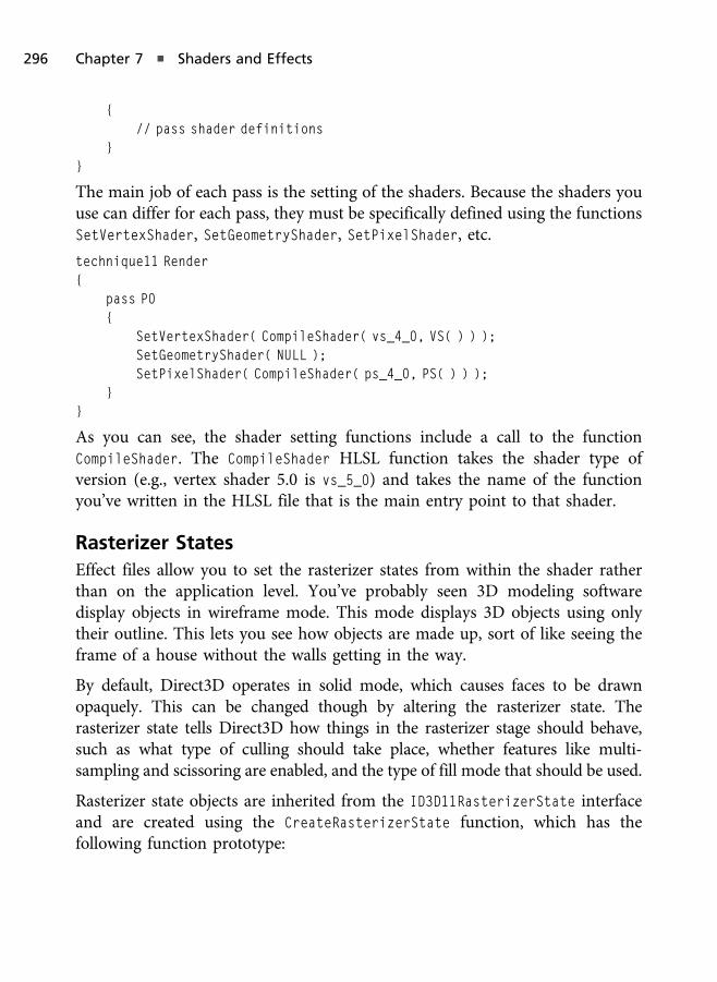
{// pass shader definitions
}}
The main job of each pass is the setting of the shaders. Because the shaders youuse can differ for each pass, they must be specifically defined using the functionsSetVertexShader, SetGeometryShader, SetPixelShader, etc.
technique11 Render{
pass P0{
SetVertexShader( CompileShader( vs_4_0, VS( ) ) );SetGeometryShader( NULL );SetPixelShader( CompileShader( ps_4_0, PS( ) ) );
}}
As you can see, the shader setting functions include a call to the functionCompileShader. The CompileShader HLSL function takes the shader type ofversion (e.g., vertex shader 5.0 is vs_5_0) and takes the name of the functionyou’ve written in the HLSL file that is the main entry point to that shader.
Rasterizer States
Effect files allow you to set the rasterizer states from within the shader ratherthan on the application level. You’ve probably seen 3D modeling softwaredisplay objects in wireframe mode. This mode displays 3D objects using onlytheir outline. This lets you see how objects are made up, sort of like seeing theframe of a house without the walls getting in the way.
By default, Direct3D operates in solid mode, which causes faces to be drawnopaquely. This can be changed though by altering the rasterizer state. Therasterizer state tells Direct3D how things in the rasterizer stage should behave,such as what type of culling should take place, whether features like multi-sampling and scissoring are enabled, and the type of fill mode that should be used.
Rasterizer state objects are inherited from the ID3D11RasterizerState interfaceand are created using the CreateRasterizerState function, which has thefollowing function prototype:
296 Chapter 7 n Shaders and Effects

HRESULT CreateRasterizerState(const D3D11_RASTERIZER_DESC* pRasterizerDesc,ID3D11RasterizerState** ppRasterizerState
);
The functions used to set states in HLSL mimic what they look like on theapplication side. The D3D11_RASTERIZER_DESC is used to define the various stateoptions and has the following structure:
typedef struct D3D11_RASTERIZER_DESC {D3D11_FILL_MODE FillMode;D3D11_CULL_MODE CullMode;BOOL FrontCounterClockwise;INT DepthBias;FLOAT DepthBiasClamp;FLOAT SlopeScaledDepthBias;BOOL DepthClipEnable;BOOL ScissorEnable;BOOL MultisampleEnable;BOOL AntialiasedLineEnable;
} D3D11_RASTERIZER_DESC;
The D3D11_FILL_MODE parameter controls how the geometry will be drawn. If youuse the value D3D11_FILL_WIREFRAME, the geometry will be drawn in wire framemode; otherwise, pass the value D3D11_FILL_SOLID to have all geometry drawn solid.
The second parameter is the culling mode parameter named D3D11_CULL_MODE.The culling mode tells the rasterizer which faces to draw and which to ignore.Imagine that you had a sphere made up of triangles. No matter which way youfaced the sphere, not all of the triangles that make it up will be visible at any onetime; only those triangles directly in front of you could be seen. The triangles onthe back of the sphere are said to be back facing. Because of how the vertices thatmake up the triangles are defined, they have a particular winding order to them.The winding order is the direction in which vertices for a triangle are defined,clockwise or counterclockwise. Because of the nature of 3D objects, even if youdefined all your triangles using the same winding order, just the act of rotatingthe object causes some of the triangles to be reversed from the camera point ofview. Going back to the sphere, from the camera’s perspective, some of thetriangles are clockwise, and some are counterclockwise. The culling mode tellsDirect3D which triangles it can safely ignore and not draw. The D3D11_CULL_MODE
Effect Files 297
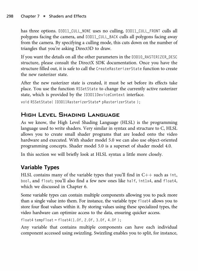
has three options. D3D11_CULL_NONE uses no culling, D3D11_CULL_FRONT culls allpolygons facing the camera, and D3D11_CULL_BACK culls all polygons facing awayfrom the camera. By specifying a culling mode, this cuts down on the number oftriangles that you’re asking Direct3D to draw.
If you want the details on all the other parameters in the D3D10_RASTERIZER_DESC
structure, please consult the DirectX SDK documentation. Once you have thestructure filled out, it is safe to call the CreateRasterizerState function to createthe new rasterizer state.
After the new rasterizer state is created, it must be set before its effects takeplace. You use the function RSSetState to change the currently active rasterizerstate, which is provided by the ID3D11DeviceContext interface.
void RSSetState( ID3D11RasterizerState* pRasterizerState );
High Level Shading Language
As we know, the High Level Shading Language (HLSL) is the programminglanguage used to write shaders. Very similar in syntax and structure to C, HLSLallows you to create small shader programs that are loaded onto the videohardware and executed. With shader model 5.0 we can also use object-orientedprogramming concepts. Shader model 5.0 is a superset of shader model 4.0.
In this section we will briefly look at HLSL syntax a little more closely.
Variable Types
HLSL contains many of the variable types that you’ll find in Cþþ such as int,bool, and float; you’ll also find a few new ones like half, int1x4, and float4,which we discussed in Chapter 6.
Some variable types can contain multiple components allowing you to pack morethan a single value into them. For instance, the variable type float4 allows you tostore four float values within it. By storing values using these specialized types, thevideo hardware can optimize access to the data, ensuring quicker access.
float4 tempFloat = float4(1.0f, 2.0f, 3.0f, 4.0f );
Any variable that contains multiple components can have each individualcomponent accessed using swizzling. Swizzling enables you to split, for instance,
298 Chapter 7 n Shaders and Effects

a float3 variable into its three components by specifying X, Y, or Z after thevariable name. Take a look at the following example; the singleFloat variable isfilled with the value found in the newFloat X component.
float3 newFloat = float3( 0.0f, 1.0f, 2.0f );float singleFloat = newFloat.x;
Any variable containing multiple components can be accessed in this way.
Semantics
Semantics are a way of letting the shader know what certain variables will beused so their access can be optimized. Semantics follow a variable declarationand have types such as COLOR0, TEXCOORD0, and POSITION. As you can see in thefollowing structure, the two variables Pos and Color are followed by semanticsspecifying their use.
struct VS_OUTPUT{
float4 Pos : SV_POSITION;float4 Color : COLOR0;
};
Some commonly used semantics include:
n SV_POSITION—A float4 value specifying a transformed position.
n NORMAL0—Semantic that is used when defining a normal vector.
n COLOR0—Semantic used when defining a color value.
There are many more semantics available; take a look at the HLSL documenta-tion in the DirectX SDK for a complete list. A lot of semantics end in anumerical value because it is possible to define multiples of those types.
Function Declarations
Functions within HLSL are defined in pretty much the same way they are withinother languages.
ReturnValue FunctionName( parameterName : semantic ){
// function code goes here}
High Level Shading Language 299
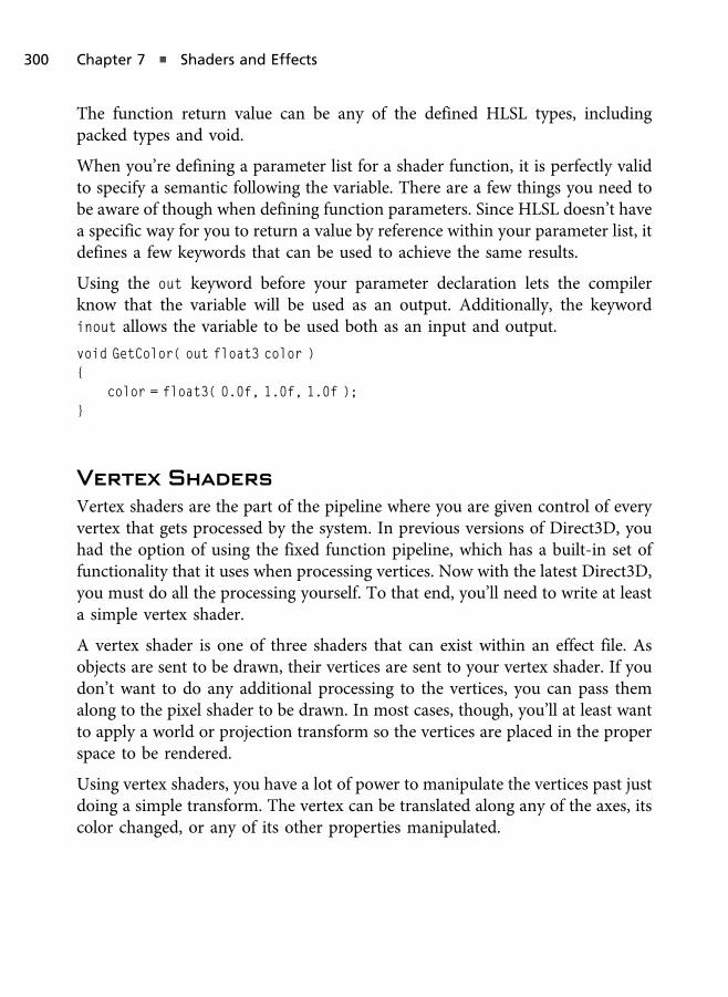
The function return value can be any of the defined HLSL types, includingpacked types and void.
When you’re defining a parameter list for a shader function, it is perfectly validto specify a semantic following the variable. There are a few things you need tobe aware of though when defining function parameters. Since HLSL doesn’t havea specific way for you to return a value by reference within your parameter list, itdefines a few keywords that can be used to achieve the same results.
Using the out keyword before your parameter declaration lets the compilerknow that the variable will be used as an output. Additionally, the keywordinout allows the variable to be used both as an input and output.
void GetColor( out float3 color ){
color = float3( 0.0f, 1.0f, 1.0f );}
Vertex Shaders
Vertex shaders are the part of the pipeline where you are given control of everyvertex that gets processed by the system. In previous versions of Direct3D, youhad the option of using the fixed function pipeline, which has a built-in set offunctionality that it uses when processing vertices. Now with the latest Direct3D,you must do all the processing yourself. To that end, you’ll need to write at leasta simple vertex shader.
A vertex shader is one of three shaders that can exist within an effect file. Asobjects are sent to be drawn, their vertices are sent to your vertex shader. If youdon’t want to do any additional processing to the vertices, you can pass themalong to the pixel shader to be drawn. In most cases, though, you’ll at least wantto apply a world or projection transform so the vertices are placed in the properspace to be rendered.
Using vertex shaders, you have a lot of power to manipulate the vertices past justdoing a simple transform. The vertex can be translated along any of the axes, itscolor changed, or any of its other properties manipulated.
300 Chapter 7 n Shaders and Effects

Pixel Shaders
Pixel shaders give you access to every pixel being put through the pipeline.Before anything is drawn, you’re given the chance to make changes to the colorof each pixel. In some cases you’ll simply return the pixel color passed in fromthe vertex or geometry shaders, but in most cases you’ll apply lighting ortextures that affect the color of the resulting pixel.
Texture Color Inversion
In this chapter we will create a simple pixel shader effect that inverts the color ofa rendered surface, which is located on the companion website in the Chapter7/ColorInversion folder. This demo will use the exact same code from Chapter 6’sCube demo, with the exception of a change we’ll be making in the pixel shaderand that we are using an effect file with a technique.
The goal of this effect is to render the colors of a surface negated. This meanswhite becomes black, black becomes white, and all other colors switch placeswith colors on the opposite side of the intensity chart. The effect to perform thisis fairly easy and requires us to do 1 minus the color in the pixel shader toperform the inversion. This makes sense because 1 minus 1 (white) will equal 0(changes white to black), whereas 1 minus 0 equals 1 (changes black to white).
The HLSL shader that performs the color inversion can be seen in Listing 7.1.This shader is exactly the same as the Cube demo from Chapter 6, with theexception that we are doing 1 � color in the pixel shader. Keep in mind thatSV_TARGET is the output semantic that specifies that the pixel shader’s output isbeing used for the rendering target. A screenshot of the running demo can beseen in Figure 7.1.
Listing 7.1 The Color Inversion demo’s HLSL shader.
Texture2D colorMap : register( t0 );SamplerState colorSampler : register( s0 );
cbuffer cbChangesEveryFrame : register( b0 ){
matrix worldMatrix;};
Pixel Shaders 301

cbuffer cbNeverChanges : register( b1 ){
matrix viewMatrix;};
cbuffer cbChangeOnResize : register( b2 ){
matrix projMatrix;};
struct VS_Input{
float4 pos : POSITION;float2 tex0 : TEXCOORD0;
};
struct PS_Input{
float4 pos : SV_POSITION;float2 tex0 : TEXCOORD0;
};
Figure 7.1
Screenshot from the Color Inversion demo.
302 Chapter 7 n Shaders and Effects

PS_Input VS_Main( VS_Input vertex ){
PS_Input vsOut = ( PS_Input )0;vsOut.pos = mul( vertex.pos, worldMatrix );vsOut.pos = mul( vsOut.pos, viewMatrix );vsOut.pos = mul( vsOut.pos, projMatrix );vsOut.tex0 = vertex.tex0;
return vsOut;}
float4 PS_Main( PS_Input frag ) : SV_TARGET{
return 1.0f - colorMap.Sample( colorSampler, frag.tex0 );}
technique11 ColorInversion{
pass P0{
SetVertexShader( CompileShader( vs_5_0, VS_Main() ) );SetGeometryShader( NULL );SetPixelShader( CompileShader( ps_5_0, PS_Main() ) );
}}
The demo class uses an effect object of the type ID3DX11Effect (seen in Listing7.2), and the code used to load the effect can be seen in the LoadContent functionin Listing 7.3, which is limited only to the code used to load the effect and thecode used to create the input layout, since the remainder of the function’scontents is not new.
Listing 7.2 The Color Inversion demo’s class definition.
#include"Dx11DemoBase.h"#include<xnamath.h>#include<d3dx11effect.h>
Pixel Shaders 303

class ColorInversionDemo : public Dx11DemoBase{
public:ColorInversionDemo( );virtual ~ColorInversionDemo( );
bool LoadContent( );void UnloadContent( );
void Update( float dt );void Render( );
private:ID3DX11Effect* effect_;ID3D11InputLayout* inputLayout_;
ID3D11Buffer* vertexBuffer_;ID3D11Buffer* indexBuffer_;
ID3D11ShaderResourceView* colorMap_;ID3D11SamplerState* colorMapSampler_;
XMMATRIX viewMatrix_;XMMATRIX projMatrix_;
};
Listing 7.3 The Color Inversion LoadContent function.
bool ColorInversionDemo::LoadContent( ){
ID3DBlob* buffer = 0;
bool compileResult = CompileD3DShader( "ColorInversion.fx", 0,"fx_5_0", &buffer );
if( compileResult == false ){
DXTRACE_MSG( "Error compiling the effect shader!" );return false;
}
304 Chapter 7 n Shaders and Effects

HRESULT d3dResult;
d3dResult = D3DX11CreateEffectFromMemory( buffer->GetBufferPointer( ),buffer->GetBufferSize( ), 0, d3dDevice_, &effect_ );
if( FAILED( d3dResult ) ){
DXTRACE_MSG( "Error creating the effect shader!" );
if( buffer )buffer->Release( );
return false;}
D3D11_INPUT_ELEMENT_DESC solidColorLayout[] ={
{ "POSITION", 0, DXGI_FORMAT_R32G32B32_FLOAT, 0, 0,D3D11_INPUT_PER_VERTEX_DATA, 0 },
{ "TEXCOORD", 0, DXGI_FORMAT_R32G32_FLOAT, 0, 12,D3D11_INPUT_PER_VERTEX_DATA, 0 }
};
unsigned int totalLayoutElements = ARRAYSIZE( solidColorLayout );
ID3DX11EffectTechnique* colorInvTechnique;colorInvTechnique = effect_->GetTechniqueByName( "ColorInversion" );ID3DX11EffectPass* effectPass = colorInvTechnique->GetPassByIndex( 0 );
D3DX11_PASS_SHADER_DESC passDesc;D3DX11_EFFECT_SHADER_DESC shaderDesc;effectPass->GetVertexShaderDesc( &passDesc );passDesc.pShaderVariable->GetShaderDesc(passDesc.ShaderIndex,
&shaderDesc);
d3dResult = d3dDevice_->CreateInputLayout( solidColorLayout,totalLayoutElements, shaderDesc.pBytecode,shaderDesc.BytecodeLength, &inputLayout_ );
buffer->Release( );
Pixel Shaders 305

if( FAILED( d3dResult ) ){
DXTRACE_MSG( "Error creating the input layout!" );return false;
}
. . .
}
In Listing 7.3 we are able to use the same CompileD3DShader code that we’ve usedthroughout this book to compile the effect file, with the exception that we arenot specifying an entry function name and that we are using a profile of“fx_5_0”, where fx represents effect files rather than “vs_5_0” for vertex shaders,“ps_5_0” for pixel shaders, etc.
When we create the input layout, we must use a vertex shader from within theeffect file that will correspond to that specific input layout. To do this we firstobtain a pointer to the technique that specifies the vertex shader we wish tobase the input layout on, which allows us to access the technique’s passes. Sinceeach pass can use a different vertex shader, we must also obtain a pointer to thepass we are basing this input layout on. Using the pass, we can call GetVer-texShaderDesc to get a description object of the vertex shader used by that pass,followed by calling that object’s GetShaderDesc function, which will provide thevertex shader’s bytecode and size. We use the bytecode and the size of that codeto create the input layout.
The last function with modified code to allow this demo to use an effect file isthe rendering code seen in Listing 7.4. In the Render function we can setconstant variables in shaders by using various effect variable objects such asID3DX11EffectShaderResourceVariable for shader resource variables, ID3D
X11EffectSamplerVariable for samplers, ID3DX11EffectMatrixVariable formatrices, and so forth.
To obtain a pointer to the variable we can use a function such as GetVaria-
bleByName (or GetVariableByIndex). We then would call a form of “AsType” toconvert it into the type we know the variable to be. For example, we would callAsShaderResource to obtain the variable as a shader resource, AsSampler toobtain it as a sampler, AsMatrix to obtain it as a matrix, and so forth.
306 Chapter 7 n Shaders and Effects

Once we have a pointer to the variable we can call various functions to bind datato it (for example, call SetMatrix of a ID3DX11EffectMatrixVariable variable topass along the data we wish to set to it). Once we’re done setting the shadervariables, we can obtain a pointer to the technique we wish to render with andloop over each pass; drawing the mesh’s geometry. The Render function is shownin Listing 7.4.
Listing 7.4 The rendering code for the Color Inversion demo.
void ColorInversionDemo::Render( ){
if( d3dContext_ == 0 )return;
float clearColor[4] = { 0.0f, 0.0f, 0.25f, 1.0f };d3dContext_->ClearRenderTargetView( backBufferTarget_, clearColor );d3dContext_->ClearDepthStencilView( depthStencilView_,
D3D11_CLEAR_DEPTH, 1.0f, 0 );
unsigned int stride = sizeof( VertexPos );unsigned int offset = 0;
d3dContext_->IASetInputLayout( inputLayout_ );d3dContext_->IASetVertexBuffers( 0, 1, &vertexBuffer_, &stride, &offset );d3dContext_->IASetIndexBuffer( indexBuffer_, DXGI_FORMAT_R16_UINT, 0 );d3dContext_->IASetPrimitiveTopology(D3D11_PRIMITIVE_TOPOLOGY_
TRIANGLELIST);
XMMATRIX rotationMat = XMMatrixRotationRollPitchYaw( 0.0f, 0.7f, 0.7f );XMMATRIX translationMat = XMMatrixTranslation( 0.0f, 0.0f, 6.0f );XMMATRIX worldMat = rotationMat * translationMat;
ID3DX11EffectShaderResourceVariable* colorMap;colorMap = effect_->GetVariableByName( "colorMap" )->AsShaderResource( );colorMap->SetResource( colorMap_ );
ID3DX11EffectSamplerVariable* colorMapSampler;colorMapSampler = effect_->GetVariableByName("colorSampler")->AsSampler( );colorMapSampler->SetSampler( 0, colorMapSampler_ );ID3DX11EffectMatrixVariable* worldMatrix;
Pixel Shaders 307

worldMatrix = effect_->GetVariableByName( "worldMatrix" )->AsMatrix( );worldMatrix->SetMatrix( ( float* )&worldMat );
ID3DX11EffectMatrixVariable* viewMatrix;viewMatrix = effect_->GetVariableByName( "viewMatrix" )->AsMatrix( );viewMatrix->SetMatrix( ( float* )&viewMatrix_ );
ID3DX11EffectMatrixVariable* projMatrix;projMatrix = effect_->GetVariableByName( "projMatrix" )->AsMatrix( );projMatrix->SetMatrix( ( float* )&projMatrix_ );
ID3DX11EffectTechnique* colorInvTechnique;colorInvTechnique = effect_->GetTechniqueByName( "ColorInversion" );
D3DX11_TECHNIQUE_DESC techDesc;colorInvTechnique->GetDesc( &techDesc );
for( unsigned int p = 0; p < techDesc.Passes; p++ ){
ID3DX11EffectPass* pass = colorInvTechnique->GetPassByIndex( p );
if( pass != 0 ){
pass->Apply( 0, d3dContext_ );d3dContext_->DrawIndexed( 36, 0, 0 );
}}
swapChain_->Present( 0, 0 );}
One last thing to note: Direct3D 11 does not offer the effect support code in thesame directories as the other includes and libraries. You can find d3dx11effect.h inthe DirectX SDK folder under Samples\Cþþ\Effects11\Inc, and you can find thesolution that we must build in Samples\Cþþ\Effects11 called Effects11_2010.sln(if you are using Visual Studio 2010). This solution is used to build a static librarythat we can link in order to use effect files in Direct3D. It is a little work to dothese extra steps the first time, but it must be done for Direct3D 11. We only needto create this static library once, and then we can reuse it for all of our projects.
308 Chapter 7 n Shaders and Effects

Color Shifting
Next we will create another simple pixel shader effect that shifts the colorcomponents of a rendered surface around, which is located on the companionwebsite in the Chapter7/ColorShift folder. This demo will also use the exactsame code from Chapter 6’s Cube demo, with the exception of a change we’ll bedoing in the pixel shader.
For this effect we will simply transpose the color components of the texture’ssampled color so that the output is Red = Blue, Blue = Green, and Green = Red. Wedo this in the pixel shader by first obtaining the texture’s color, and then we createanother float4 object to store the new shifted component values. The HLSL shaderfor this effect can be seen in Listing 7.5, and a screenshot can be seen in Figure 7.2.
Listing 7.5 The Color Shift demo’s HLSL shader.
Texture2D colorMap : register( t0 );SamplerState colorSampler : register( s0 );
cbuffer cbChangesEveryFrame : register( b0 ){
Figure 7.2
Screenshot from the Color Shift demo.
Pixel Shaders 309
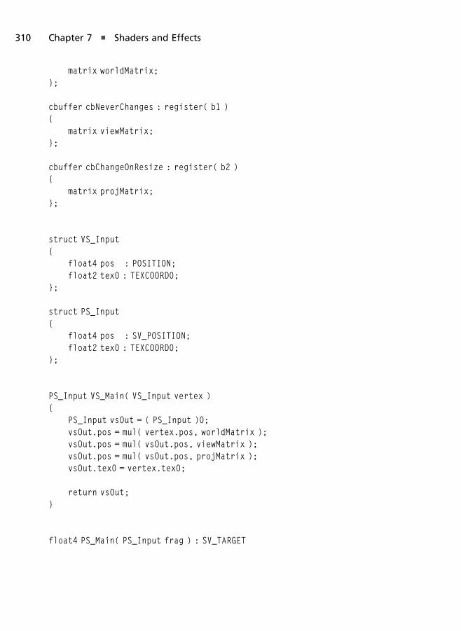
matrix worldMatrix;};
cbuffer cbNeverChanges : register( b1 ){
matrix viewMatrix;};
cbuffer cbChangeOnResize : register( b2 ){
matrix projMatrix;};
struct VS_Input{
float4 pos : POSITION;float2 tex0 : TEXCOORD0;
};
struct PS_Input{
float4 pos : SV_POSITION;float2 tex0 : TEXCOORD0;
};
PS_Input VS_Main( VS_Input vertex ){
PS_Input vsOut = ( PS_Input )0;vsOut.pos = mul( vertex.pos, worldMatrix );vsOut.pos = mul( vsOut.pos, viewMatrix );vsOut.pos = mul( vsOut.pos, projMatrix );vsOut.tex0 = vertex.tex0;
return vsOut;}
float4 PS_Main( PS_Input frag ) : SV_TARGET
310 Chapter 7 n Shaders and Effects
{float4 col = colorMap.Sample( colorSampler, frag.tex0 );float4 finalCol;
finalCol.x = col.y;finalCol.y = col.z;finalCol.z = col.x;finalCol.w = 1.0f;
return finalCol;}
technique11 ColorShift{
pass P0{
SetVertexShader( CompileShader( vs_5_0, VS_Main() ) );SetGeometryShader( NULL );SetPixelShader( CompileShader( ps_5_0, PS_Main() ) );
}}
Multitexturing
The last demo we will create will perform multitexturing, which is located on thecompanion website in the Chapter7/ColorShift folder. Multitexturing is an effectthat displays two texture images on one surface. We can do this by sampling bothtexture images and using color1� color2 as the final pixel’s results.
Multitexturing can be a useful technique. Sometimes we need to perform taskssuch as light mapping, shadow mapping, detail mapping, etc., and the ability touse multiple images at one time does come in handy.
For the Multitexture demo we load a second texture image and pass that alongto our shader like we do the first texture. Listing 7.6 shows the MultiTextureDemo
class with the added resource view for the second texture. Throughout thedemo’s code we can simply copy the same code we used for the first texture anduse it for the second. Within the shader’s code we simply sample both textureimages and multiply their results to get the final render. Keep in mind that the
Pixel Shaders 311

second texture uses t1, while the first uses t0 in the HLSL file, which can be seenin Listing 7.7. A screenshot of the effect can be seen in Figure 7.3.
Listing 7.6 The Multitexture demo’s class with added texture.
class MultiTextureDemo : public Dx11DemoBase{
public:MultiTextureDemo( );virtual ~MultiTextureDemo( );
bool LoadContent( );void UnloadContent( );
void Update( float dt );void Render( );
private:ID3DX11Effect* effect_;ID3D11InputLayout* inputLayout_;
ID3D11Buffer* vertexBuffer_;
Figure 7.3
Multitexture demo.
312 Chapter 7 n Shaders and Effects

ID3D11Buffer* indexBuffer_;
ID3D11ShaderResourceView* colorMap_;ID3D11ShaderResourceView* secondMap_;ID3D11SamplerState* colorMapSampler_;
XMMATRIX viewMatrix_;XMMATRIX projMatrix_;
};
Listing 7.7 Multitexture demo’s HLSL source code.
Texture2D colorMap : register( t0 );Texture2D secondMap : register( t1 );SamplerState colorSampler : register( s0 );
cbuffer cbChangesEveryFrame : register( b0 ){
matrix worldMatrix;};
cbuffer cbNeverChanges : register( b1 ){
matrix viewMatrix;};
cbuffer cbChangeOnResize : register( b2 ){
matrix projMatrix;};
struct VS_Input{
float4 pos : POSITION;float2 tex0 : TEXCOORD0;
};
struct PS_Input{
Pixel Shaders 313

float4 pos : SV_POSITION;float2 tex0 : TEXCOORD0;
};
PS_Input VS_Main( VS_Input vertex ){
PS_Input vsOut = ( PS_Input )0;vsOut.pos = mul( vertex.pos, worldMatrix );vsOut.pos = mul( vsOut.pos, viewMatrix );vsOut.pos = mul( vsOut.pos, projMatrix );vsOut.tex0 = vertex.tex0;
return vsOut;}
float4 PS_Main( PS_Input frag ) : SV_TARGET{
float4 col = colorMap.Sample( colorSampler, frag.tex0 );float4 col2 = secondMap.Sample( colorSampler, frag.tex0 );
return col * col2;}
Geometry Shaders
Geometry shaders are a bit more complicated than the shaders you’ve workedwith so far. Unlike vertex and pixel shaders, geometry shaders are able to outputmore or less than they take in. Vertex shaders must accept a single vertex andoutput a single vertex; pixel shaders work the same way. Geometry shaders, onthe other hand, can be used to remove or add vertices as they pass through thisportion of the pipeline. This is useful if you want to clip geometry based on someset criteria, or maybe you want to increase the resolution of the object throughtessellation.
Geometry shaders exist within an effect file between the vertex and pixel shaderstages. Since geometry shaders are optional, you may commonly see them set toa null value in effect techniques. When a geometry shader is necessary, though, itis set in an identical way as vertex and pixel shaders.
314 Chapter 7 n Shaders and Effects

To give you an example of what geometry shaders can do, take a look at thefollowing code. It contains the full geometry shader function, along with thestructures and constant buffer to support it. The job of this particular shader isto take as input a single point from a point list and generate a full triangle tosend along to the pixel shader.
cbuffer TriangleVerts{
float3 triPositions[3] ={
float3( -0.25, 0.25, 0 ),float3( 0.25, 0.25, 0 ),float3( -0.25, -0.25, 0 )
};};
struct VS_OUTPUT{
float4 Pos : SV_POSITION;float4 Color : COLOR0;
};
[maxvertexcount(3)]void GS( point VS_OUTPUT input[1], inout TriangleStream<VS_OUTPUT>triangleStream ){
VS_OUTPUT psInput;
for( int i = 0; i < 3; i++ ){
float3 position = triPositions[i];
position = position + input[0].Pos;
psInput.Pos = mul( float4( position, 1.0f ), Projection );psInput.Color = input[0].Color;
triangleStream.Append( psInput );
Geometry Shaders 315

}}
Geometry Shader Function Declaration
Geometry shaders are declared slightly differently than vertex and pixel shaders.Instead of designating the return type for the function, the vertices this shaderoutputs are done so in the parameter list. The geometry shader itself has a returntype of void.
Every geometry shader needs to designate the number of vertices that it willreturn and must be declared above the function using the maxvertexcount
keyword. This particular function is meant to return a single triangle, so threevertices are required.
[maxvertexcount(3)]void GS( point VS_OUTPUT input[1],
inout TriangleStream<VS_OUTPUT> triangleStream )
Geometry shader functions take two parameters. The first parameter is an arrayof vertices for the incoming geometry. The type of geometry being passed intothis function is based on the topology you used in your application code. Sincethis example uses a point list, the type of geometry coming into the function is apoint, and there is only one item in the array. If the application used a trianglelist, the type would be set as triangle, and three vertices would be in the array.
The second parameter is the stream object. The stream object is the list ofvertices that are output from the geometry shader and passed to the next shaderstage. This list of vertices must use the structure format that is used as the inputto the pixel shader. Based on the type of geometry you’re creating within thisshader, there are three stream object types available: PointStream, Triangle-
Stream, and LineStream.
When adding vertices to a stream object, it will be occasionally necessary to end thestrip being created. In that instance, you should make a call to the restartstrip
function. This is useful when generating a series of interconnected triangles.
The Geometry Shader Explained
The geometry shader in the previous example generates three vertices for everypoint from a point list passed to it. The vertices are created by taking the initial
316 Chapter 7 n Shaders and Effects

position vertex and merging it with the vertex positions found in the triPositions
variable. This variable holds a list of three vertices that are used to create a triangleat any position.
Because each triangle the shader is trying to create requires three vertices, a for-loop within the shader loops three times, generating a new vertex for each pointof the triangle.
The final triangle points are then multiplied by the projection matrix to createthe final positions. Each point in the triangle is added to the triangle stream afterits creation.
Introduction to Lighting
In this section we’ll take a quick look at performing lighting in Direct3D. Wewill use code based on the Models demo from Chapter 8 to demonstrate theeffect on a complex object, but we’ll defer explaining the model loading part ofthe demo until you reach the “Models” section in the next chapter. In thischapter, we’ll talk about lighting in general and the shaders used to achieve it.Once you finish Chapter 8 you will see how all of the demo’s code ties together.
Real-time lighting in games is evaluated these days in shaders, where lightingequations performed in vertex shaders are known as per-vertex lighting, andlighting done in the pixel shader is known as per-pixel lighting. Since there aremany more pixels than vertices, and those pixels are extremely close together indistance, the lighting quality of performing these equations in a pixel shader isoften much higher.
There are also a number of different algorithms for performing lighting. In thischapter we’ll examine a simple algorithm for performing the effect based on thestandard lighting model used by Direct3D during the fixed-function pipeline days.
In general, the rendering equation in computer graphics is highly complex, mathintensive, and definitely something you’ll need to research once you start tomove toward advanced lighting topics, global illumination, and shadows, but inthis chapter we will examine the three most common parts of this equation.These parts are known as the ambient, diffuse, and specular terms. Since this is abeginner’s book, we will briefly touch upon the easiest to understand concepts toat least introduce you to the topic for later use.
Geometry Shaders 317

The Ambient Term
The ambient term is a value used to simulate light that has bounced off of theenvironment and onto the surface being shaded. In its basic form this is just acolor value that is added to the total lighting value such as float4( 0.3f, 0.3f,
0.3f, 1.0f). In reality this term is nothing more than a solid color that slightlybrightens the scene, which is highly unrealistic—an example of which can beseen in Figure 7.4.
In more complex lighting equations such as various global illuminationalgorithms and other techniques such as ambient occlusion, the value thatrepresents bounced light is highly realistic and complex but often not possible todo in real time.
The Diffuse Term
The diffuse term is used to simulate light that has bounced off of a surface andinto your eyes. This is not the same as light that has bounced off of other objectsin the environment first and then off of the surface being shaded, which can beused to simulate many different phenomena, such as light bleeding in globalillumination, soft shadows, etc.
Figure 7.4
Ambient-only light.
318 Chapter 7 n Shaders and Effects
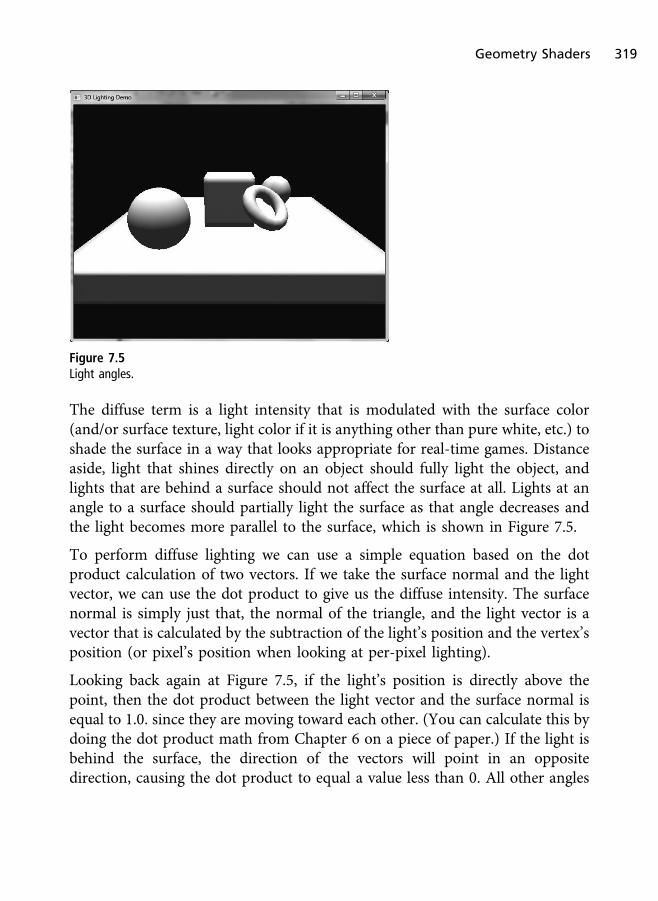
The diffuse term is a light intensity that is modulated with the surface color(and/or surface texture, light color if it is anything other than pure white, etc.) toshade the surface in a way that looks appropriate for real-time games. Distanceaside, light that shines directly on an object should fully light the object, andlights that are behind a surface should not affect the surface at all. Lights at anangle to a surface should partially light the surface as that angle decreases andthe light becomes more parallel to the surface, which is shown in Figure 7.5.
To perform diffuse lighting we can use a simple equation based on the dotproduct calculation of two vectors. If we take the surface normal and the lightvector, we can use the dot product to give us the diffuse intensity. The surfacenormal is simply just that, the normal of the triangle, and the light vector is avector that is calculated by the subtraction of the light’s position and the vertex’sposition (or pixel’s position when looking at per-pixel lighting).
Looking back again at Figure 7.5, if the light’s position is directly above thepoint, then the dot product between the light vector and the surface normal isequal to 1.0. since they are moving toward each other. (You can calculate this bydoing the dot product math from Chapter 6 on a piece of paper.) If the light isbehind the surface, the direction of the vectors will point in an oppositedirection, causing the dot product to equal a value less than 0. All other angles
Figure 7.5
Light angles.
Geometry Shaders 319
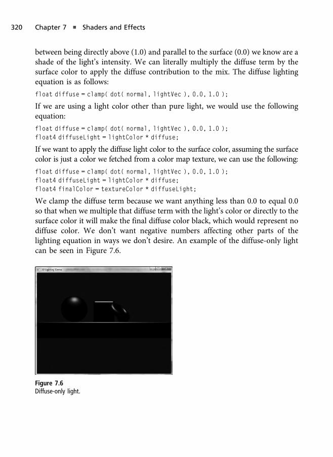
between being directly above (1.0) and parallel to the surface (0.0) we know are ashade of the light’s intensity. We can literally multiply the diffuse term by thesurface color to apply the diffuse contribution to the mix. The diffuse lightingequation is as follows:
float diffuse = clamp( dot( normal, lightVec ), 0.0, 1.0 );
If we are using a light color other than pure light, we would use the followingequation:
float diffuse = clamp( dot( normal, lightVec ), 0.0, 1.0 );float4 diffuseLight = lightColor * diffuse;
If we want to apply the diffuse light color to the surface color, assuming the surfacecolor is just a color we fetched from a color map texture, we can use the following:
float diffuse = clamp( dot( normal, lightVec ), 0.0, 1.0 );float4 diffuseLight = lightColor * diffuse;float4 finalColor = textureColor * diffuseLight;
We clamp the diffuse term because we want anything less than 0.0 to equal 0.0so that when we multiple that diffuse term with the light’s color or directly to thesurface color it will make the final diffuse color black, which would represent nodiffuse color. We don’t want negative numbers affecting other parts of thelighting equation in ways we don’t desire. An example of the diffuse-only lightcan be seen in Figure 7.6.
Figure 7.6
Diffuse-only light.
320 Chapter 7 n Shaders and Effects
Specular Term
Specular lighting is similar to diffuse lighting, with the exception that specularlighting simulates sharp reflections of light as it bounces off of an object and hitsthe eyes. Diffuse light is used for rough surfaces, where the more microscopicbumpiness of a surface (the rougher it is) will cause light to scatter in a patternthat generally looks even in all directions. This is why if you rotate a highlydiffuse lit object or view it from another angle, the intensity should remain thesame.
With specular light, the smoothness of the surface is what will cause light toreflect back in its mirror direction. The smoother the surface is, the more sharplight reflections can be observed. Take for example a shiny piece of metal. Thesmoothness of this surface will cause light to reflect more sharply thanchaotically (like diffuse). In computer graphics this creates the highlight yousee on shiny objects. On non-shiny or smooth surfaces, the specular light willbe low or non existent. When we model our surfaces, we must mix the rightamount of diffuse and specular light to create a believable effect. For example, aslice of bread would not be as shiny as a metal ball. A mirror in real life is sosmooth that light reflects in such a way that we can see a perfect mirror imageon the surface. Another example can be seen with soft drink bottles, where ifyou rotate the object in your hand, the shiny highlight will seem to move anddance as the rotational relationship with the surface and the light sourcechanges.
From the description of diffuse and specular light, we can say that diffuse light isnot view dependent, but specular light is. That means the equation to performspecular light will use the camera vector instead of the light vector. The cameravector is the vector calculated from:
float4 cameraVec = cameraPosition – vertexPosition;
From the camera vector we can create what is also known as the half vector. Wecan then calculate the specular contribution using the following equation:
float3 halfVec = normalize( lightVec + cameraVec );
float specularTerm = pow( saturate( dot( normal, halfVec ) ), 25 );
An example of specular-only lighting can be seen in Figure 7.7.
Geometry Shaders 321
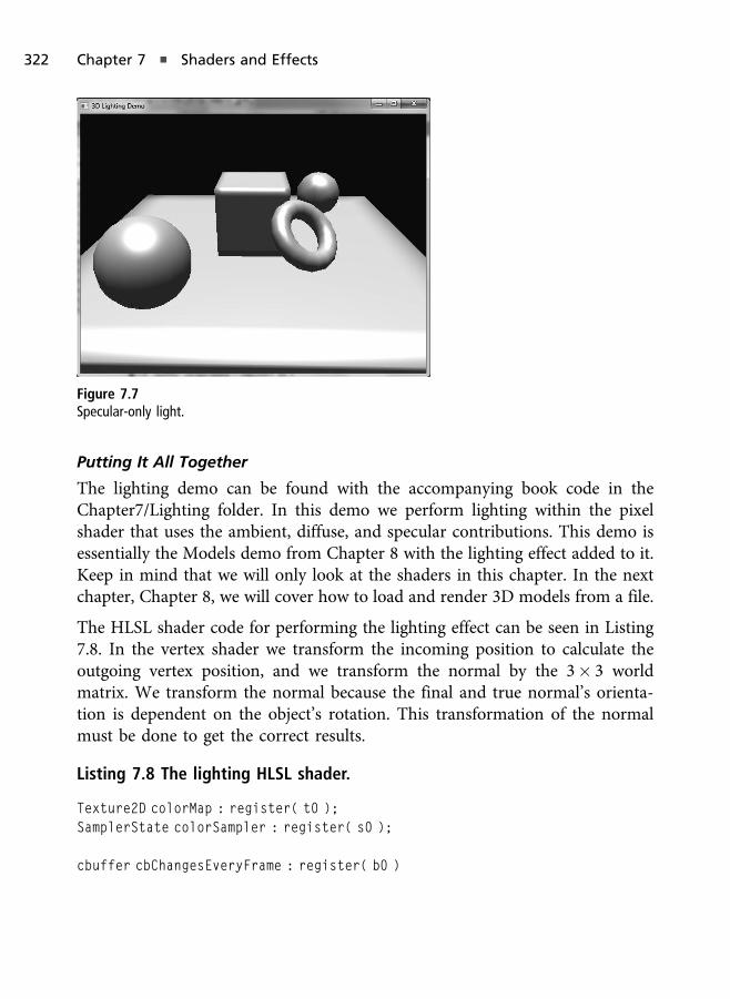
Putting It All Together
The lighting demo can be found with the accompanying book code in theChapter7/Lighting folder. In this demo we perform lighting within the pixelshader that uses the ambient, diffuse, and specular contributions. This demo isessentially the Models demo from Chapter 8 with the lighting effect added to it.Keep in mind that we will only look at the shaders in this chapter. In the nextchapter, Chapter 8, we will cover how to load and render 3D models from a file.
The HLSL shader code for performing the lighting effect can be seen in Listing7.8. In the vertex shader we transform the incoming position to calculate theoutgoing vertex position, and we transform the normal by the 3� 3 worldmatrix. We transform the normal because the final and true normal’s orienta-tion is dependent on the object’s rotation. This transformation of the normalmust be done to get the correct results.
Listing 7.8 The lighting HLSL shader.
Texture2D colorMap : register( t0 );SamplerState colorSampler : register( s0 );
cbuffer cbChangesEveryFrame : register( b0 )
Figure 7.7
Specular-only light.
322 Chapter 7 n Shaders and Effects
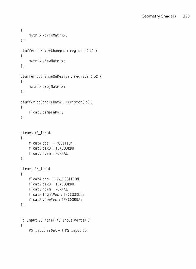
{matrix worldMatrix;
};
cbuffer cbNeverChanges : register( b1 ){
matrix viewMatrix;};
cbuffer cbChangeOnResize : register( b2 ){
matrix projMatrix;};
cbuffer cbCameraData : register( b3 ){
float3 cameraPos;};
struct VS_Input{
float4 pos : POSITION;float2 tex0 : TEXCOORD0;float3 norm : NORMAL;
};
struct PS_Input{
float4 pos : SV_POSITION;float2 tex0 : TEXCOORD0;float3 norm : NORMAL;float3 lightVec : TEXCOORD1;float3 viewVec : TEXCOORD2;
};
PS_Input VS_Main( VS_Input vertex ){
PS_Input vsOut = ( PS_Input )0;
Geometry Shaders 323

float4 worldPos = mul( vertex.pos, worldMatrix );vsOut.pos = mul( worldPos, viewMatrix );vsOut.pos = mul( vsOut.pos, projMatrix );
vsOut.tex0 = vertex.tex0;vsOut.norm = mul( vertex.norm, (float3x3)worldMatrix );vsOut.norm = normalize( vsOut.norm );
float3 lightPos = float3( 0.0f, 500.0f, 50.0f );vsOut.lightVec = normalize( lightPos - worldPos );
vsOut.viewVec = normalize( cameraPos - worldPos );
return vsOut;}
float4 PS_Main( PS_Input frag ) : SV_TARGET{
float3 ambientColor = float3( 0.2f, 0.2f, 0.2f );float3 lightColor = float3( 0.7f, 0.7f, 0.7f );
float3 lightVec = normalize( frag.lightVec );float3 normal = normalize( frag.norm );
float diffuseTerm = clamp( dot( normal, lightVec ), 0.0f, 1.0f );float specularTerm = 0;
if( diffuseTerm > 0.0f ){
float3 viewVec = normalize( frag.viewVec );float3 halfVec = normalize( lightVec + viewVec );
specularTerm = pow( saturate( dot( normal, halfVec ) ), 25 );}
float3 finalColor = ambientColor + lightColor *diffuseTerm + lightColor * specularTerm;
324 Chapter 7 n Shaders and Effects

return float4( finalColor, 1.0f );}
In the pixel shader we use a constant for the ambient term, perform N dot L (thedot product of the surface normal and the light vector) to find the diffusecontribution, and we perform N dot H (dot product of the normal and halfvector) to find the specular contribution. We add all of these terms together toget the final light color. Take note that we are assuming a white diffuse andspecular color, but if you want, you can adjust these colors to see how the resultschange the final output. As a bonus exercise, you can use constant buffervariables to specify the light color, camera position, and light position to allowyou to manipulate these values with the keyboard to see how it affects the litobject in real time.
Summary
You should now be familiar with at least the basics of shader programming andwhat benefits it provides. The best way to continue learning shader program-ming is to play around with the shader code you’ve already written and see whateffects you can come up with. A small change can have profound effects.
This chapter served as a brief reference to the level of shaders we’ve been writingthroughout this book. There is a lot that can be done with HLSL, and much oflearning to master it is to practice and experiment.
What You Have Learned
n How to write vertex, pixel, and geometry shaders
n How to use the High Level Shading Language
n How to provide lighting in your scene
Chapter Questions
You can find the answers to the chapter review questions in Appendix A on thisbook’s companion website.
1. Effect files are loaded using which function?
2. What is HLSL?
Chapter Questions 325

3. What is the purpose of a geometry shader?
4. What is the purpose of domain and hull shaders?
5. What are the two modes the rasterizer can operate in?
6. Define semantics.
7. What are compute shaders, and what is the lowest version that can beused?
8. Define HLSL techniques and passes.
9. What is the fixed function pipeline? How does Direct3D 11 make use ofit?
10. What is the tessellator unit used for?
On Your Own
1. Implement an effect file with a single technique and pass and render anobject using it.
2. Build off of the previous “On Your Own” and take all of the shaders cre-ated in demos throughout this chapter and place them in a single effectfile. Create a different technique for each effect. On the application side,allow the user to switch between the rendering techniques being appliedby using the arrow keys.
3. Modify the lighting demo to allow you to move the light position usingthe arrow keys of the keyboard. To do this you will need to send thelight’s position to the shader via a constant buffer.
326 Chapter 7 n Shaders and Effects

Cameras and Models in
Direct3D
The topic of cameras in 3D scenes is often overlooked. The camera is a veryimportant actor in the game scene, and the cameras seen in today’s games areoften fairly complex. Cameras are critical because if the camera is frustrating orbad in any way, the gamer can have a negative opinion of the experience.
In this chapter we will look at two topics briefly. The first is the creation of twodifferent types of cameras, and the second will show us how to load 3D modelsfrom a file.
In this chapter you will learn:
n How to create a look-at camera
n How to create an arc rotation camera
n How to load models in OBJ format
Cameras in Direct3D
In game programming we create a view matrix that represents the virtualcamera. This view matrix in XNA Math can be created with a function called
Chapter 8
327

XMMatrixLookAtLH (the right-handed version is XMMatrixLookAtRH), which hasthe following prototype:
XMMATRIX XMMatrixLookAtLH(XMVECTOR EyePosition,XMVECTOR FocusPosition,XMVECTOR UpDirection
);
The XMMatrixLookAtLH function takes the position of the camera, the positionthe camera is looking at, and the direction that points up in the game world. Inaddition to XMMatrixLookAtLH, we could have alternatively used XMMatrixLookToLH,which has the following prototype:
XMMATRIX XMMatrixLookToLH(XMVECTOR EyePosition,XMVECTOR EyeDirection,XMVECTOR UpDirection
);
The difference between XMMatrixLookAtLH and XMMatrixLookToLH is that thesecond function specifies a direction to look toward, not a fixed point to look at.When building cameras, the idea is that we want to manipulate the properties ofour camera during the game’s update, and when it comes time to draw from thecamera’s perspective, we generate the three vectors that are passed to one ofthese matrix functions.
In this chapter we will create a stationary look-at camera and a camera thatrotates around a point along an arc.
Look-At Camera Demo
Stationary cameras are fairly straightforward; their purpose is to sit at a locationand look in a direction. There are two main types of stationary cameras: fixed-position and dynamic position. Fixed-position cameras are given a set position,and that position does not change. This was used heavily in the original ResidentEvil games. Dynamic fixed-position cameras are those cameras whose position isdynamically placed in the game world—for example in Halo Reach, when theplayer drives off a cliff and the chase camera turns into a stationary camera atthe moment it is determined that the player has passed a certain plane and isconsidered dead.
328 Chapter 8 n Cameras and Models in Direct3D
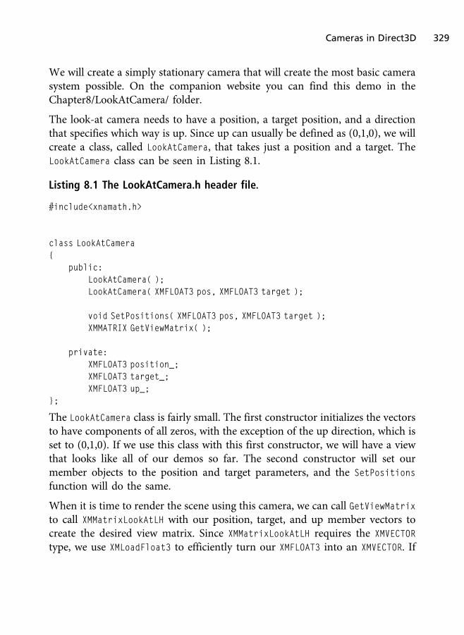
We will create a simply stationary camera that will create the most basic camerasystem possible. On the companion website you can find this demo in theChapter8/LookAtCamera/ folder.
The look-at camera needs to have a position, a target position, and a directionthat specifies which way is up. Since up can usually be defined as (0,1,0), we willcreate a class, called LookAtCamera, that takes just a position and a target. TheLookAtCamera class can be seen in Listing 8.1.
Listing 8.1 The LookAtCamera.h header file.
#include<xnamath.h>
class LookAtCamera{
public:LookAtCamera( );LookAtCamera( XMFLOAT3 pos, XMFLOAT3 target );
void SetPositions( XMFLOAT3 pos, XMFLOAT3 target );XMMATRIX GetViewMatrix( );
private:XMFLOAT3 position_;XMFLOAT3 target_;XMFLOAT3 up_;
};
The LookAtCamera class is fairly small. The first constructor initializes the vectorsto have components of all zeros, with the exception of the up direction, which isset to (0,1,0). If we use this class with this first constructor, we will have a viewthat looks like all of our demos so far. The second constructor will set ourmember objects to the position and target parameters, and the SetPositions
function will do the same.
When it is time to render the scene using this camera, we can call GetViewMatrixto call XMMatrixLookAtLH with our position, target, and up member vectors tocreate the desired view matrix. Since XMMatrixLookAtLH requires the XMVECTOR
type, we use XMLoadFloat3 to efficiently turn our XMFLOAT3 into an XMVECTOR. If
Cameras in Direct3D 329

we wanted to use XMVECTOR as our member variables, we’d have to align thememory of the class and take special care in order to get the code to correctlycompile.
The functions for the LookAtCamera class can be seen in Listing 8.2.
Listing 8.2 The functions for the LookAtCamera class.
#include<d3d11.h>#include"LookAtCamera.h"
LookAtCamera::LookAtCamera( ) : position_( XMFLOAT3( 0.0f, 0.0f, 0.0f ) ),target_( XMFLOAT3( 0.0f, 0.0f, 0.0f ) ), up_( XMFLOAT3( 0.0f, 1.0f, 0.0f ) )
{
}
LookAtCamera::LookAtCamera( XMFLOAT3 pos, XMFLOAT3 target ) :position_( pos ), target_( target ), up_( XMFLOAT3( 0.0f, 1.0f, 0.0f ) )
{
}
void LookAtCamera::SetPositions( XMFLOAT3 pos, XMFLOAT3 target ){
position_ = pos;target_ = target;
}
XMMATRIX LookAtCamera::GetViewMatrix( ){
XMMATRIX viewMat = XMMatrixLookAtLH( XMLoadFloat3( &position_ ),XMLoadFloat3( &target_ ), XMLoadFloat3( &up_ ) );
return viewMat;}
330 Chapter 8 n Cameras and Models in Direct3D

The demo’s class, called CameraDemo, builds directly off of the 3DCube demofrom Chapter 6. The difference here is that we are adding our stationarycamera to the demo, and before we render we will obtain the view matrixfrom this camera. The CameraDemo class with our new camera can be seen inListing 8.3.
Listing 8.3 The CameraDemo class.
#include"Dx11DemoBase.h"#include"LookAtCamera.h"
class CameraDemo : public Dx11DemoBase{
public:CameraDemo( );virtual ~CameraDemo( );
bool LoadContent( );void UnloadContent( );
void Update( float dt );void Render( );
private:ID3D11VertexShader* solidColorVS_;ID3D11PixelShader* solidColorPS_;
ID3D11InputLayout* inputLayout_;ID3D11Buffer* vertexBuffer_;ID3D11Buffer* indexBuffer_;
ID3D11ShaderResourceView* colorMap_;ID3D11SamplerState* colorMapSampler_;
ID3D11Buffer* viewCB_;ID3D11Buffer* projCB_;ID3D11Buffer* worldCB_;XMMATRIX projMatrix_;
Cameras in Direct3D 331
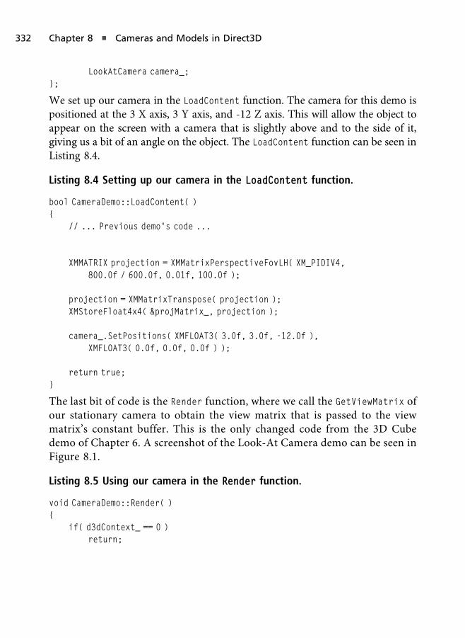
LookAtCamera camera_;};
We set up our camera in the LoadContent function. The camera for this demo ispositioned at the 3 X axis, 3 Y axis, and -12 Z axis. This will allow the object toappear on the screen with a camera that is slightly above and to the side of it,giving us a bit of an angle on the object. The LoadContent function can be seen inListing 8.4.
Listing 8.4 Setting up our camera in the LoadContent function.
bool CameraDemo::LoadContent( ){
// ... Previous demo’s code ...
XMMATRIX projection = XMMatrixPerspectiveFovLH( XM_PIDIV4,800.0f / 600.0f, 0.01f, 100.0f );
projection = XMMatrixTranspose( projection );XMStoreFloat4x4( &projMatrix_, projection );
camera_.SetPositions( XMFLOAT3( 3.0f, 3.0f, -12.0f ),XMFLOAT3( 0.0f, 0.0f, 0.0f ) );
return true;}
The last bit of code is the Render function, where we call the GetViewMatrix ofour stationary camera to obtain the view matrix that is passed to the viewmatrix’s constant buffer. This is the only changed code from the 3D Cubedemo of Chapter 6. A screenshot of the Look-At Camera demo can be seen inFigure 8.1.
Listing 8.5 Using our camera in the Render function.
void CameraDemo::Render( ){
if( d3dContext_ == 0 )return;
332 Chapter 8 n Cameras and Models in Direct3D

float clearColor[4] = { 0.0f, 0.0f, 0.25f, 1.0f };d3dContext_->ClearRenderTargetView( backBufferTarget_, clearColor );d3dContext_->ClearDepthStencilView( depthStencilView_,
D3D11_CLEAR_DEPTH, 1.0f, 0 );
unsigned int stride = sizeof( VertexPos );unsigned int offset = 0;
d3dContext_->IASetInputLayout( inputLayout_ );d3dContext_->IASetVertexBuffers( 0, 1, &vertexBuffer_, &stride, &offset );d3dContext_->IASetIndexBuffer( indexBuffer_, DXGI_FORMAT_R16_UINT, 0 );d3dContext_->IASetPrimitiveTopology(D3D11_PRIMITIVE_TOPOLOGY_TRIANGLELIST);
d3dContext_->VSSetShader( solidColorVS_, 0, 0 );d3dContext_->PSSetShader( solidColorPS_, 0, 0 );d3dContext_->PSSetShaderResources( 0, 1, &colorMap_ );d3dContext_->PSSetSamplers( 0, 1, &colorMapSampler_ );
XMMATRIX worldMat = XMMatrixIdentity( );worldMat = XMMatrixTranspose( worldMat );
Figure 8.1
A screenshot of the Look-At Camera demo.
Cameras in Direct3D 333

XMMATRIX viewMat = camera_.GetViewMatrix( );viewMat = XMMatrixTranspose( viewMat );
d3dContext_->UpdateSubresource( worldCB_, 0, 0, &worldMat, 0, 0 );d3dContext_->UpdateSubresource( viewCB_, 0, 0, &viewMat, 0, 0 );d3dContext_->UpdateSubresource( projCB_, 0, 0, & projMatrix_, 0, 0 );
d3dContext_->VSSetConstantBuffers( 0, 1, &worldCB_ );d3dContext_->VSSetConstantBuffers( 1, 1, &viewCB_ );d3dContext_->VSSetConstantBuffers( 2, 1, &projCB_ );
d3dContext_->DrawIndexed( 36, 0, 0 );
swapChain_->Present( 0, 0 );}
Arc-Ball Camera Demo
The next camera we will create will be an arc-ball camera. This type of camera isgood for editors or moments in a game where an object is the target and thecamera needs to rotate around that target in a spherical manner. The code forthis demo can be found on the companion website in the Chapter8/ArcBallCamera/ folder.
For this demo we will need a few things. Since the target position is the one thecamera is focusing on, it is the one position that is supplied. The camera’sposition itself will rotate around the target, meaning that the position will becalculated in the GetViewMatrix function.
Another set of properties we can use for this type of camera is the distance fromthe object and restraints along the X axis rotation. The distance will work as azoom, allowing us to move closer or further from the target position. Therestraints will allow us to rotate along an arc 180 degrees, which will keep ourcamera from reaching a rotation where it is then upside down.
Listing 8.6 shows the ArcCamera class. Its members includes the current distancethe camera is from the target position, the min and max distance the camera canbe if we want to limit how close or how far the camera can be, and the X and Yrotation values. We also have the min and max rotation values so that we can addrestraints to the camera.
334 Chapter 8 n Cameras and Models in Direct3D

Listing 8.6 The ArcCamera class.
#include<xnamath.h>
class ArcCamera{
public:ArcCamera( );
void SetDistance(float distance, float minDistance, float maxDistance);void SetRotation( float x, float y, float minY, float maxY );void SetTarget( XMFLOAT3& target );
void ApplyZoom( float zoomDelta );void ApplyRotation( float yawDelta, float pitchDelta );
XMMATRIX GetViewMatrix( );
private:XMFLOAT3 position_;XMFLOAT3 target_;
float distance_, minDistance_, maxDistance_;float xRotation_, yRotation_, yMin_, yMax_;
};
The arc camera has a constructor that defaults a target at the origin, a position atthe origin, a distance of two units away from the target, and a set of rotationrestraints that total 180 degrees (�90 to 90). The restraints allow us to go all theway up to the highest peak before the camera starts to turn upside down. SinceGetViewMatrix will calculate the position, the constructor is simply giving it adefault value that will eventually be replaced with a real position.
The other functions are SetDistance, which will set the current distance fromthe camera as well as setting the new min and max distance limits, SetRotation toset the current X and Y rotation as well as its limits, and SetTarget, which willset the current target position. Each of these functions is straightforward and canbe seen in Listing 8.7.
Cameras in Direct3D 335

Listing 8.7 Initializing functions of the ArcCamera.
ArcCamera::ArcCamera( ) : target_( XMFLOAT3( 0.0f, 0.0f, 0.0f ) ),position_( XMFLOAT3( 0.0f, 0.0f, 0.0f ) )
{SetDistance( 2.0f, 1.0f, 10.0f );SetRotation( 0.0f, 0.0f, -XM_PIDIV2, XM_PIDIV2 );
}
void ArcCamera::SetDistance( float distance, float minDistance,float maxDistance )
{distance_ = distance;minDistance_ = minDistance;maxDistance_ = maxDistance;
if( distance_ < minDistance_ ) distance_ = minDistance_;if( distance_ > maxDistance_ ) distance_ = maxDistance_;
}
void ArcCamera::SetRotation( float x, float y, float minY, float maxY ){
xRotation_ = x;yRotation_ = y;yMin_ = minY;yMax_ = maxY;
if( yRotation_ < yMin_ ) yRotation_ = yMin_;if( yRotation_ > yMax_ ) yRotation_ = yMax_;
}
void ArcCamera::SetTarget( XMFLOAT3& target ){
target_ = target;}
Next we have our functions to apply movement. First is the ApplyZoom
function, which will increase or decrease the distance amount while clamping
336 Chapter 8 n Cameras and Models in Direct3D
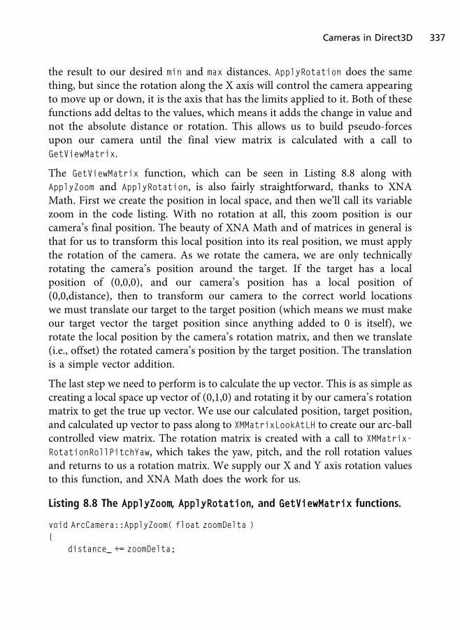
the result to our desired min and max distances. ApplyRotation does the samething, but since the rotation along the X axis will control the camera appearingto move up or down, it is the axis that has the limits applied to it. Both of thesefunctions add deltas to the values, which means it adds the change in value andnot the absolute distance or rotation. This allows us to build pseudo-forcesupon our camera until the final view matrix is calculated with a call toGetViewMatrix.
The GetViewMatrix function, which can be seen in Listing 8.8 along withApplyZoom and ApplyRotation, is also fairly straightforward, thanks to XNAMath. First we create the position in local space, and then we’ll call its variablezoom in the code listing. With no rotation at all, this zoom position is ourcamera’s final position. The beauty of XNA Math and of matrices in general isthat for us to transform this local position into its real position, we must applythe rotation of the camera. As we rotate the camera, we are only technicallyrotating the camera’s position around the target. If the target has a localposition of (0,0,0), and our camera’s position has a local position of(0,0,distance), then to transform our camera to the correct world locationswe must translate our target to the target position (which means we must makeour target vector the target position since anything added to 0 is itself), werotate the local position by the camera’s rotation matrix, and then we translate(i.e., offset) the rotated camera’s position by the target position. The translationis a simple vector addition.
The last step we need to perform is to calculate the up vector. This is as simple ascreating a local space up vector of (0,1,0) and rotating it by our camera’s rotationmatrix to get the true up vector. We use our calculated position, target position,and calculated up vector to pass along to XMMatrixLookAtLH to create our arc-ballcontrolled view matrix. The rotation matrix is created with a call to XMMatrix-
RotationRollPitchYaw, which takes the yaw, pitch, and the roll rotation valuesand returns to us a rotation matrix. We supply our X and Y axis rotation valuesto this function, and XNA Math does the work for us.
Listing 8.8 The ApplyZoom, ApplyRotation, and GetViewMatrix functions.
void ArcCamera::ApplyZoom( float zoomDelta ){
distance_ += zoomDelta;
Cameras in Direct3D 337
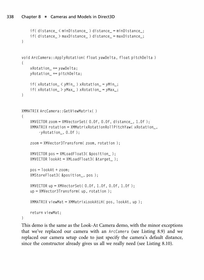
if( distance_ < minDistance_ ) distance_ = minDistance_;if( distance_ > maxDistance_ ) distance_ = maxDistance_;
}
void ArcCamera::ApplyRotation( float yawDelta, float pitchDelta ){
xRotation_ += yawDelta;yRotation_ += pitchDelta;
if( xRotation_ < yMin_ ) xRotation_ = yMin_;if( xRotation_ > yMax_ ) xRotation_ = yMax_;
}
XMMATRIX ArcCamera::GetViewMatrix( ){
XMVECTOR zoom = XMVectorSet( 0.0f, 0.0f, distance_, 1.0f );XMMATRIX rotation = XMMatrixRotationRollPitchYaw( xRotation_,
-yRotation_, 0.0f );
zoom = XMVector3Transform( zoom, rotation );
XMVECTOR pos = XMLoadFloat3( &position_ );XMVECTOR lookAt = XMLoadFloat3( &target_ );
pos = lookAt + zoom;XMStoreFloat3( &position_, pos );
XMVECTOR up = XMVectorSet( 0.0f, 1.0f, 0.0f, 1.0f );up = XMVector3Transform( up, rotation );
XMMATRIX viewMat = XMMatrixLookAtLH( pos, lookAt, up );
return viewMat;}
This demo is the same as the Look-At Camera demo, with the minor exceptionsthat we’ve replaced our camera with an ArcCamera (see Listing 8.9) and wereplaced our camera setup code to just specify the camera’s default distance,since the constructor already gives us all we really need (see Listing 8.10).
338 Chapter 8 n Cameras and Models in Direct3D

Listing 8.9 The Arc Camera demo‘s application class.
#include"Dx11DemoBase.h"#include"ArcCamera.h"#include<XInput.h>
class CameraDemo2 : public Dx11DemoBase{
public:CameraDemo2( );virtual ~CameraDemo2( );
bool LoadContent( );void UnloadContent( );
void Update( float dt );void Render( );
private:ID3D11VertexShader* solidColorVS_;ID3D11PixelShader* solidColorPS_;
ID3D11InputLayout* inputLayout_;ID3D11Buffer* vertexBuffer_;ID3D11Buffer* indexBuffer_;
ID3D11ShaderResourceView* colorMap_;ID3D11SamplerState* colorMapSampler_;
ID3D11Buffer* viewCB_;ID3D11Buffer* projCB_;ID3D11Buffer* worldCB_;XMMATRIX projMatrix_;
ArcCamera camera_;
XINPUT_STATE controller1State_;XINPUT_STATE prevController1State_;
};
Cameras in Direct3D 339
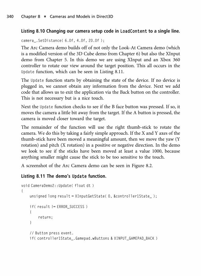
Listing 8.10 Changing our camera setup code in LoadContent to a single line.
camera_.SetDistance( 6.0f, 4.0f, 20.0f );
The Arc Camera demo builds off of not only the Look-At Camera demo (whichis a modified version of the 3D Cube demo from Chapter 6) but also the XInputdemo from Chapter 5. In this demo we are using XInput and an Xbox 360controller to rotate our view around the target position. This all occurs in theUpdate function, which can be seen in Listing 8.11.
The Update function starts by obtaining the state of the device. If no device isplugged in, we cannot obtain any information from the device. Next we addcode that allows us to exit the application via the Back button on the controller.This is not necessary but is a nice touch.
Next the Update function checks to see if the B face button was pressed. If so, itmoves the camera a little bit away from the target. If the A button is pressed, thecamera is moved closer toward the target.
The remainder of the function will use the right thumb-stick to rotate thecamera. We do this by taking a fairly simple approach. If the X and Y axes of thethumb-stick have been moved a meaningful amount, then we move the yaw (Yrotation) and pitch (X rotation) in a positive or negative direction. In the demowe look to see if the sticks have been moved at least a value 1000, becauseanything smaller might cause the stick to be too sensitive to the touch.
A screenshot of the Arc Camera demo can be seen in Figure 8.2.
Listing 8.11 The demo‘s Update function.
void CameraDemo2::Update( float dt ){
unsigned long result = XInputGetState( 0, &controller1State_ );
if( result != ERROR_SUCCESS ){
return;}
// Button press event.if( controller1State_.Gamepad.wButtons & XINPUT_GAMEPAD_BACK )
340 Chapter 8 n Cameras and Models in Direct3D

{PostQuitMessage( 0 );
}
// Button up event.if( ( prevController1State_.Gamepad.wButtons & XINPUT_GAMEPAD_B ) &&
!( controller1State_.Gamepad.wButtons & XINPUT_GAMEPAD_B ) )
{camera_.ApplyZoom( -1.0f );
}
// Button up event.if( ( prevController1State_.Gamepad.wButtons & XINPUT_GAMEPAD_A ) &&
!( controller1State_.Gamepad.wButtons & XINPUT_GAMEPAD_A ) )
{camera_.ApplyZoom( 1.0f );
}
Figure 8.2
A screenshot of the Arc Camera demo.
Cameras in Direct3D 341
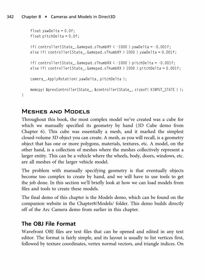
float yawDelta = 0.0f;float pitchDelta = 0.0f;
if( controller1State_.Gamepad.sThumbRY < -1000 ) yawDelta = -0.001f;else if( controller1State_.Gamepad.sThumbRY > 1000 ) yawDelta = 0.001f;
if( controller1State_.Gamepad.sThumbRX < -1000 ) pitchDelta = -0.001f;else if( controller1State_.Gamepad.sThumbRX > 1000 ) pitchDelta = 0.001f;
camera_.ApplyRotation( yawDelta, pitchDelta );
memcpy( &prevController1State_, &controller1State_, sizeof( XINPUT_STATE ) );}
Meshes and Models
Throughout this book, the most complex model we’ve created was a cube forwhich we manually specified its geometry by hand (3D Cube demo fromChapter 6). This cube was essentially a mesh, and it marked the simplestclosed-volume 3D object you can create. A mesh, as you will recall, is a geometryobject that has one or more polygons, materials, textures, etc. A model, on theother hand, is a collection of meshes where the meshes collectively represent alarger entity. This can be a vehicle where the wheels, body, doors, windows, etc.are all meshes of the larger vehicle model.
The problem with manually specifying geometry is that eventually objectsbecome too complex to create by hand, and we will have to use tools to getthe job done. In this section we’ll briefly look at how we can load models fromfiles and tools to create these models.
The final demo of this chapter is the Models demo, which can be found on thecompanion website in the Chapter8/Models/ folder. This demo builds directlyoff of the Arc Camera demo from earlier in this chapter.
The OBJ File Format
Wavefront OBJ files are text files that can be opened and edited in any texteditor. The format is fairly simple, and its layout is usually to list vertices first,followed by texture coordinates, vertex normal vectors, and triangle indices. On
342 Chapter 8 n Cameras and Models in Direct3D
each line is a different piece of information, and the starting character dictateswhat the rest of the line represents. For example, lines that are comments startwith a # symbol, which can be seen as follows:
# 1104 triangles in group
Vertex position is on lines that start with a v. Each value after the v is for the X,Y, and Z positions, each separated by a whitespace. An example can be seen inthe following:
v 0.000000 2.933333 -0.000000
Texture coordinates start with a vt and have two floating-point values thatfollow the keyword, and normals start with a vn. An example of each is asfollowing:
vt 1.000000 0.916667vn 0.000000 -1.000000 0.000000
Triangle information is on lines that start with an f. After the f there are threegroups of values. Each group has the vertex position index into the vertex list,texture coordinate index into the texture coordinate list, and normal index intothe normal list. Since each vertex position, texture coordinate, and normalspecified in the file are unique, the face information in an OBJ file is not thesame as indices using indexed geometry. When using index geometry, we haveone index that is used for all attributes of a vertex (i.e., position, texturecoordinate, etc.), whereas in the OBJ file it has separate indices for eachattribute. An example of a triangle in the OBJ file can be seen in the following,where each index is separated by a /, and each group (vertex) is separated by awhitespace:
f 2/1/1 3/2/2 4/3/3
There are other keywords in an OBJ file. The keyword mtllib is used to specifythe material file used by the mesh:
mtllib Sphere.mtl
The usemtl keyword is used to specify that the following mesh is to use thematerial specified in the file loaded by mtllib:
usemtl Material01
And the g keyword specifies the start of a new mesh:
g Sphere02
Meshes and Models 343

Reading Tokens from a File
The OBJ file is simply a text file. Each piece of information we want to read is onits own line, which means we need to write code that can parse lines of text froma file and break down the lines into smaller pieces of text. These smaller pieces oftext are called tokens.
To do this we’ll create a simple class that can return to use tokens from within atext file. This class is called TokenStream, and it can be found in TokenStream.hand TokenStream.cpp in the Chapter8/Models/ folder on the companionwebsite. Listing 8.12 shows the TokenStream.h header file.
Listing 8.12 The TokenStream.h header file.
class TokenStream{
public:TokenStream( );
void ResetStream( );
void SetTokenStream( char* data );
bool GetNextToken( std::string* buffer, char* delimiters,int totalDelimiters );
bool MoveToNextLine( std::string *buffer );
private:int startIndex_, endIndex_;std::string data_;
};
The TokenStream object will just store the entire file’s data and the current readindices (start and end) that mark the current positions it is reading from. We’llsee how this is used soon. First we’ll look at the constructor, ResetStream, andSetTokenStream functions in Listing 8.13. The constructor and ResetStream
simply set the read indices to 0, and SetTokenStream will set the data membervariable that will store the file’s text.
344 Chapter 8 n Cameras and Models in Direct3D

Listing 8.13 The constructor, ResetStream, and SetTokenStream functions.
TokenStream::TokenStream( ){
ResetStream( );}
void TokenStream::ResetStream( ){
startIndex_ = endIndex_ = 0;}
void TokenStream::SetTokenStream( char *data ){
ResetStream( );data_ = data;
}
Next are two helper functions from the TokenStream.cpp source file. These functionssimply test whether or not a character is a delimiter. A delimiter is a character thatmarks the separation of text. Taking the following text as an example, we can see thateach word is separated by a whitespace. This whitespace is the delimiter.
“Hello world. How are you?”
The first isValidIdentifier function simply looks to see if the character is anumber, letter, or symbol. This is usually used as a default check, whereas theoverloaded isValidIdentifier function will check the character with an array ofdesired delimiters. If you open the spheres.obj model file for this demo, you willsee that the only delimiters in this file are new lines, whitespaces, and /. TheisValidIdentifier functions are listed in Listing 8.14.
Listing 8.14 The isValidIdentifier functions.
bool isValidIdentifier( char c ){
// Ascii from ! to ~.if( ( int )c > 32 && ( int )c < 127 )
return true;
Meshes and Models 345

return false;}
bool isValidIdentifier( char c, char* delimiters, int totalDelimiters ){
if( delimiters == 0 || totalDelimiters == 0 )return isValidIdentifier( c );
for( int i = 0; i < totalDelimiters; i++ ){
if( c == delimiters[i] )return false;
}
return true;}
The next function is GetNextToken. This function will loop through the text untilit reaches a delimiter. Once it finds a delimiter, it uses the start index (theposition at which it began reading) and the end index (the position before thedelimiter) to identify a token. This token is returned to the caller as the firstparameter, which is the address of the object that will return this token. Thefunction also returns true or false, depending on whether it was able to find anew token (which can be used to determine when we have reached the end ofthe data buffer). The GetNextToken function can be seen in Listing 8.15.
Listing 8.15 The GetNextToken function.
bool TokenStream::GetNextToken( std::string* buffer, char* delimiters,int totalDelimiters )
{startIndex_ = endIndex_;
bool inString = false;int length = ( int )data_.length( );
if( startIndex_ >= length - 1 )return false;
346 Chapter 8 n Cameras and Models in Direct3D
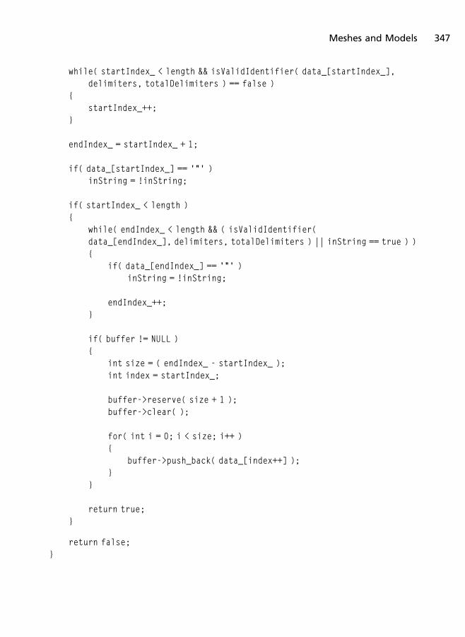
while( startIndex_ < length && isValidIdentifier( data_[startIndex_],delimiters, totalDelimiters ) == false )
{startIndex_++;
}
endIndex_ = startIndex_ + 1;
if( data_[startIndex_] == ’"’ )inString = !inString;
if( startIndex_ < length ){
while( endIndex_ < length && ( isValidIdentifier(data_[endIndex_], delimiters, totalDelimiters ) || inString == true ) ){
if( data_[endIndex_] == ’"’ )inString = !inString;
endIndex_++;}
if( buffer != NULL ){
int size = ( endIndex_ - startIndex_ );int index = startIndex_;
buffer->reserve( size + 1 );buffer->clear( );
for( int i = 0; i < size; i++ ){
buffer->push_back( data_[index++] );}
}
return true;}
return false;}
Meshes and Models 347
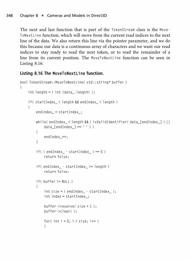
The next and last function that is part of the TokenStream class is the Move-
ToNextLine function, which will move from the current read indices to the nextline of the data. We also return this line via the pointer parameter, and we dothis because our data is a continuous array of characters and we want our readindices to stay ready to read the next token, or to read the remainder of aline from its current position. The MoveToNextLine function can be seen inListing 8.16.
Listing 8.16 The MoveToNextLine function.
bool TokenStream::MoveToNextLine( std::string* buffer ){
int length = ( int )data_.length( );
if( startIndex_ < length && endIndex_ < length ){
endIndex_ = startIndex_;
while( endIndex_ < length && ( isValidIdentifier( data_[endIndex_] ) ||data_[endIndex_] == ’ ’ ) )
{endIndex_++;
}
if( ( endIndex_ - startIndex_ ) == 0 )return false;
if( endIndex_ - startIndex_ >= length )return false;
if( buffer != NULL ){
int size = ( endIndex_ - startIndex_ );int index = startIndex_;
buffer->reserve( size + 1 );buffer->clear( );
for( int i = 0; i < size; i++ ){
348 Chapter 8 n Cameras and Models in Direct3D
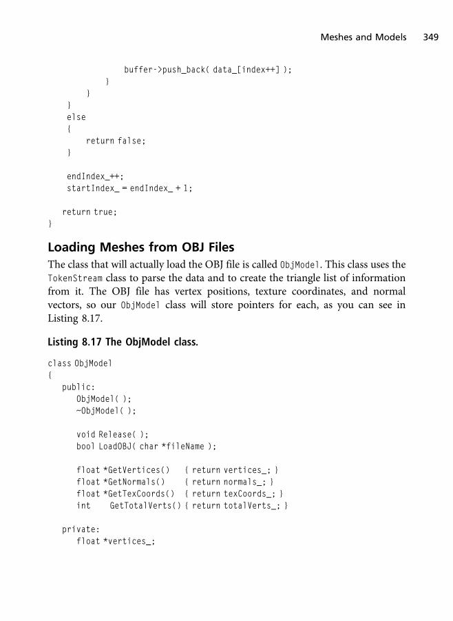
buffer->push_back( data_[index++] );}
}}else{
return false;}
endIndex_++;startIndex_ = endIndex_ + 1;
return true;}
Loading Meshes from OBJ Files
The class that will actually load the OBJ file is called ObjModel. This class uses theTokenStream class to parse the data and to create the triangle list of informationfrom it. The OBJ file has vertex positions, texture coordinates, and normalvectors, so our ObjModel class will store pointers for each, as you can see inListing 8.17.
Listing 8.17 The ObjModel class.
class ObjModel{
public:ObjModel( );~ObjModel( );
void Release( );bool LoadOBJ( char *fileName );
float *GetVertices() { return vertices_; }float *GetNormals() { return normals_; }float *GetTexCoords() { return texCoords_; }int GetTotalVerts() { return totalVerts_; }
private:float *vertices_;
Meshes and Models 349

float *normals_;float *texCoords_;int totalVerts_;
};
The LoadOBJ function (seen in Listing 8.18 and Listing 8.19) is more straightfor-ward than it appears. The function first opens a file and determines the size ofthe file in bytes. It then reads this information into a temporary buffer that isthen passed to a TokenStream object.
The first TokenStream object is used to read lines out of the data by callingMoveToNextLine. We’ll use a second TokenStream object to further parse eachindividual line for the specific information we are looking for.
When we parse a line, we look at the first character of the line to determine whatinformation it has. If it starts with a v it is a position, if it starts with a vt it is atexture coordinate, or if it starts with a vn it is a vertex normal. We can use thewhitespace delimiter to break down these lines into their components.
If we are reading a face (triangle indices) from the file, which appears after the f
keyword, then we need to use another TokenStream object to break down theindices using the whitespace and / characters as a delimiter.
Listing 8.18 The first half of the LoadOBJ function.
bool ObjModel::LoadOBJ( char *fileName ){
std::ifstream fileStream;int fileSize = 0;
fileStream.open( fileName, std::ifstream::in );
if( fileStream.is_open( ) == false )return false;
fileStream.seekg( 0, std::ios::end );fileSize = ( int )fileStream.tellg( );fileStream.seekg( 0, std::ios::beg );
if( fileSize <= 0 )return false;
350 Chapter 8 n Cameras and Models in Direct3D

char *buffer = new char[fileSize];
if( buffer == 0 )return false;
memset( buffer, ’\0’, fileSize );
TokenStream tokenStream, lineStream, faceStream;std::string tempLine, token;
fileStream.read( buffer, fileSize );tokenStream.SetTokenStream( buffer );
delete[] buffer;
tokenStream.ResetStream( );
std::vector<float> verts, norms, texC;std::vector<int> faces;
char lineDelimiters[2] = { ’\n’, ’ ’ };
while( tokenStream.MoveToNextLine( &tempLine ) ){
lineStream.SetTokenStream( ( char* )tempLine.c_str( ) );tokenStream.GetNextToken( 0, 0, 0 );
if( !lineStream.GetNextToken( &token, lineDelimiters, 2 ) )continue;
if( strcmp( token.c_str( ), "v" ) == 0 ){
lineStream.GetNextToken( &token, lineDelimiters, 2 );verts.push_back( ( float )atof( token.c_str( ) ) );
lineStream.GetNextToken( &token, lineDelimiters, 2 );verts.push_back( ( float )atof( token.c_str( ) ) );
lineStream.GetNextToken( &token, lineDelimiters, 2 );verts.push_back( ( float )atof( token.c_str( ) ) );
}
Meshes and Models 351

else if( strcmp( token.c_str( ), "vn" ) == 0 ){
lineStream.GetNextToken( &token, lineDelimiters, 2 );norms.push_back( ( float )atof( token.c_str( ) ) );
lineStream.GetNextToken( &token, lineDelimiters, 2 );norms.push_back( ( float )atof( token.c_str( ) ) );
lineStream.GetNextToken( &token, lineDelimiters, 2 );norms.push_back( ( float )atof( token.c_str( ) ) );
}else if( strcmp( token.c_str( ), "vt" ) == 0 ){
lineStream.GetNextToken( &token, lineDelimiters, 2 );texC.push_back( ( float )atof( token.c_str( ) ) );
lineStream.GetNextToken( &token, lineDelimiters, 2 );texC.push_back( ( float )atof( token.c_str( ) ) );
}else if( strcmp( token.c_str( ), "f" ) == 0 ){
char faceTokens[3] = { ’\n’, ’ ’, ’/’ };std::string faceIndex;
faceStream.SetTokenStream( ( char* )tempLine.c_str( ) );faceStream.GetNextToken( 0, 0, 0 );
for( int i = 0; i < 3; i++ ){
faceStream.GetNextToken( &faceIndex, faceTokens, 3 );faces.push_back( ( int )atoi( faceIndex.c_str( ) ) );
faceStream.GetNextToken( &faceIndex, faceTokens, 3 );faces.push_back( ( int )atoi( faceIndex.c_str( ) ) );
faceStream.GetNextToken( &faceIndex, faceTokens, 3 );faces.push_back( ( int )atoi( faceIndex.c_str( ) ) );
}}else if( strcmp( token.c_str( ), "#" ) == 0 ){
352 Chapter 8 n Cameras and Models in Direct3D
int a = 0;int b = a;
}
token[0] = ’\0’;}
Once we have the data, we use the face information to generate a triangle listarray of geometry. We cannot use the information in an OBJ file directly becausethe indices are defined per attribute, not per vertex. Once we generate theinformation in a manner Direct3D will be happy with, we return true afterreleasing all of our temporary data. The second half of the LoadOBJ function canbe seen in Listing 8.19.
Listing 8.19 The second half of the LoadOBJ function.
{// "Unroll" the loaded obj information into a list of triangles.
int vIndex = 0, nIndex = 0, tIndex = 0;int numFaces = ( int )faces.size( ) / 9;
totalVerts_ = numFaces * 3;
vertices_ = new float[totalVerts_ * 3];
if( ( int )norms.size( ) != 0 ){
normals_ = new float[totalVerts_ * 3];}
if( ( int )texC.size( ) != 0 ){
texCoords_ = new float[totalVerts_ * 2];}
for( int f = 0; f < ( int )faces.size( ); f+=3 ){
vertices_[vIndex + 0] = verts[( faces[f + 0] - 1 ) * 3 + 0];vertices_[vIndex + 1] = verts[( faces[f + 0] - 1 ) * 3 + 1];vertices_[vIndex + 2] = verts[( faces[f + 0] - 1 ) * 3 + 2];
Meshes and Models 353

vIndex += 3;
if(texCoords_){
texCoords_[tIndex + 0] = texC[( faces[f + 1] - 1 ) * 2 + 0];texCoords_[tIndex + 1] = texC[( faces[f + 1] - 1 ) * 2 + 1];tIndex += 2;
}
if(normals_){
normals_[nIndex + 0] = norms[( faces[f + 2] - 1 ) * 3 + 0];normals_[nIndex + 1] = norms[( faces[f + 2] - 1 ) * 3 + 1];normals_[nIndex + 2] = norms[( faces[f + 2] - 1 ) * 3 + 2];nIndex += 3;
}}
verts.clear( );norms.clear( );texC.clear( );faces.clear( );
return true;}
The last code to look at lies within LoadContent. When we load our OBJ model,we create a new ObjModel object, called LoadOBJ, and use the pointers to theattributes to fill out our vertex structure array that will be passed to the vertexbuffer. Once this information is in our vertex buffer, it is rendered as a normaltriangle list, and our model should appear on the screen. You can try manydifferent models of different complexities with this code besides the spheremodel that comes with the demo. The code specific to loading the vertex buffercan be seen in Listing 8.20. A screenshot of the demo can be seen in Figure 8.3.
Listing 8.20 The code in LoadContent specific to loading the vertex buffer.
// Load the models from the file.ObjModel objModel;
354 Chapter 8 n Cameras and Models in Direct3D
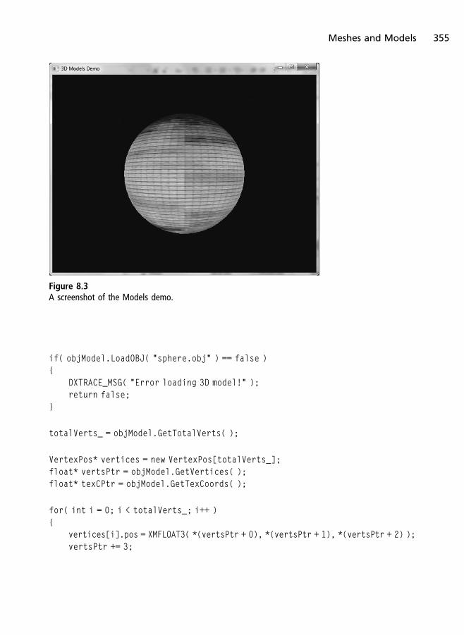
if( objModel.LoadOBJ( "sphere.obj" ) == false ){
DXTRACE_MSG( "Error loading 3D model!" );return false;
}
totalVerts_ = objModel.GetTotalVerts( );
VertexPos* vertices = new VertexPos[totalVerts_];float* vertsPtr = objModel.GetVertices( );float* texCPtr = objModel.GetTexCoords( );
for( int i = 0; i < totalVerts_; i++ ){
vertices[i].pos = XMFLOAT3( *(vertsPtr + 0), *(vertsPtr + 1), *(vertsPtr + 2) );vertsPtr += 3;
Figure 8.3
A screenshot of the Models demo.
Meshes and Models 355

vertices[i].tex0 = XMFLOAT2( *(texCPtr + 0), *(texCPtr + 1) );texCPtr += 2;
}
D3D11_BUFFER_DESC vertexDesc;ZeroMemory( &vertexDesc, sizeof( vertexDesc ) );vertexDesc.Usage = D3D11_USAGE_DEFAULT;vertexDesc.BindFlags = D3D11_BIND_VERTEX_BUFFER;vertexDesc.ByteWidth = sizeof( VertexPos ) * totalVerts_;
D3D11_SUBRESOURCE_DATA resourceData;ZeroMemory( &resourceData, sizeof( resourceData ) );resourceData.pSysMem = vertices;
d3dResult = d3dDevice_->CreateBuffer( &vertexDesc, &resourceData,&vertexBuffer_ );
if( FAILED( d3dResult ) ){
DXTRACE_MSG( "Failed to create vertex buffer!" );return false;
}
delete[] vertices;objModel.Release( );
Advanced Topics
This chapter has just begun to scratch the surface of what is possible in 3D videogame scenes. Although some of these topics can quickly become quite advanced,some of them you can begin to experiment with sooner rather than later. Justlooking at the camera code we wrote earlier in this chapter should give you anindication that, with a little more work, you can create a camera system thatallows you to create a wide range of various viewports for many different typesof games.
In this section we will take a moment to discuss some topics that, even as abeginner, you can begin to explore once you are done with this book. With theright art assets, you can even create some impressive-looking demos or gamesusing these general ideas as a foundation.
356 Chapter 8 n Cameras and Models in Direct3D

Complex Cameras
We touched upon two types of cameras in this chapter. The first camera was asimple stationary camera that had properties that directly fed the creation of thelook-at view matrix. This type of camera has its purposes, but it alone would nothave been enough to adequately discuss cameras in Direct3D.
The second type of camera was a little more useful when examining our 3Dobjects. The arc camera allowed us to freely rotate along the X axis, as well asimpose limited rotations along the Y axis. Many 3D editors use cameras similarto this, where the target position becomes the driving force of the view, and theposition is determined dynamically based upon rotation around that target.
There are many more cameras we could create in our 3D games. Following is alimited list of some of the more common 3D camera systems:
n First-person
n Free (ghost)
n Chase (third-person)
n Flight
n Scripted
n AI
n Framing
First-person cameras are used greatly in first-person shooting games. With afirst-person camera, the player is given the perspective of seeing through theavatar’s eyes. In first-person shooters (FPS), the player’s weapon(s) and parts ofthe avatar’s body can be visible, along with any interface elements such as cross-hairs to help with aiming. Epic Game's UDK (Figure 8.4) is a prime example ofthe first-person camera.
A free camera, also known as a ghost camera, is a cam that is able to freely movearound the environment in all axes. This type of camera is often done in spectatormodes of popular FPS games such as the sample demo from the UDK (Figure 8.5),in replay modes such as Bungie’s Halo Reach Theater, and many more. Although afree camera might or might not physically interact with the game world viacollisions, it often has free flight throughout the scene with very few restrictions inmovement.
Advanced Topics 357

Figure 8.4
First-person view in the UDK sample demo.
Figure 8.5
Free camera in Epic’s UDK sample.
358 Chapter 8 n Cameras and Models in Direct3D

A chase camera is the type of camera that chases an object inside of the scene.This is commonly used for third-person games (see Figure 8.6), flight games,etc., where the player’s camera is usually stationed behind the avatar. Thesecameras also have damping effects so that the camera gradually catches up to therotation instead of moving as if it was attach to a rigid pole.
In flight games we often have many different types of cameras working together.There is the cockpit view that acts as a first-person camera, there are stationarycameras during replays, there can be free cameras for guided missiles androckets, and there are chase cameras for a flight view behind the avatar (airplane,jet, etc.). In a modified version of the Chase Camera (Figure 8.7) sample demofor XNA Game Studio Express (available from http://create.msdn.com), thechase camera also has the ability to turn into an arc camera when the player usesthe right joystick to arc around the aircraft while the left stick controls theaircraft, causing the chase camera to “chase” after it.
Scripted and artificial intelligence guided cameras are controlled by sourcesother than the player. For scripted cameras we can script the camera’s move-ments and play it back in real time. Scripting a camera, along with scripting themovements and animations of game objects and models, makes it possible tocreate real-time, in-game cinematic scenes, also known as cut-scenes.
Figure 8.6
Chase camera in UDK’s sample demo.
Advanced Topics 359
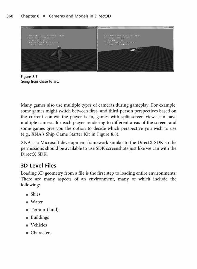
Many games also use multiple types of cameras during gameplay. For example,some games might switch between first- and third-person perspectives based onthe current context the player is in, games with split-screen views can havemultiple cameras for each player rendering to different areas of the screen, andsome games give you the option to decide which perspective you wish to use(e.g., XNA’s Ship Game Starter Kit in Figure 8.8).
XNA is a Microsoft development framework similar to the DirectX SDK so thepermissions should be available to use SDK screenshots just like we can with theDirectX SDK.
3D Level Files
Loading 3D geometry from a file is the first step to loading entire environments.There are many aspects of an environment, many of which include thefollowing:
n Skies
n Water
n Terrain (land)
n Buildings
n Vehicles
n Characters
Figure 8.7
Going from chase to arc.
360 Chapter 8 n Cameras and Models in Direct3D

n Weapons
n Power-ups
n Trigger volumes (i.e., areas that trigger an event, like a cut-scene)
n Environment props (e.g., rocks, trees, grass, brush, etc.)
n Objective game props (e.g., flags for Capture the Flag, hill locations, etc.)
n And much more
There is a wide range of different objects you can have in a virtual world, someof which are not visible. In today’s games, game levels are too large to manuallyspecify by hand, and often an editor of some form is used. We generally refer tothese as map or level editors.
Creating a level editor is no easy task and can often be very game specific. Thefile format that represents the game level is also highly game specific. As a quickexample, let’s look at a simple sample file that stores nothing but positions,rotations, and scaling information for 3D models. Take a look at the following:
Level Level1{
PlayerStart 0,0,-100 0,0,0 1,1,1WeaponStart Pistol
Weapons{
Figure 8.8
Switching camera perspective based on personal preference in XNA’s Ship Game Starter Kit.
Advanced Topics 361

Pistol -421,66,932 0,90,0 1,1,1Sniper 25,532,235 0,0,0 1,1,1RocketLauncher 512,54,336 0,0,0, 1,1,1...
}
Enemies{
...}
Scripts{
...}
Triggers{
...}
}
In the example above, imagine that PlayerStart specified the player’s startingposition, rotation, and scale in the game world when the level starts, andWeaponStart specifies which weapon the player has in his possession at thestart. Let’s imagine that all of the weapons and their starting positions in the gameworld are defined within the Weapons block, the enemies within the Enemies
block, and the scripts and triggers in their own blocks. If scripts load upon thelevel’s start, then triggers could potentially be invisible areas within the gameworld that trigger an action whenever the player enters it (such as opening a doorwhen a player is near it, playing a cut-scene, etc.).
Even with this extremely basic and imaginary level file, you can already see thatwe barely have the details of many common games, and we’ve barely specifiedenough detail for the objects listed as is. Although this is not a real format of anykind, the amount of properties and information you can have for a single objector group of objects can become quite involved. Being able to create objects and
362 Chapter 8 n Cameras and Models in Direct3D

edit them in an application can help make creating levels much easier and muchmore time efficient. Today many game companies utilize art tools such as 3DStudio Max or Maya and write custom exporters that create not just individualobjects but the level/world data files that are loaded by the game.
Summary
The goal of this chapter was to introduce two simple 3D cameras that you canuse to help you learn how to create additional types of cameras later on. Thischapter also showed how to load models from the OBJ file format, which many3D modeling applications support. The OBJ file format is a simple format tostart off with because it is a simple-to-read text file with straightforward syntax.
What You Have Learned
n How to create a look-at (stationary) camera
n How to create an arc-ball camera
n How to load meshes from an OBJ file
Chapter Questions
You can find the answers to chapter review questions in Appendix A on thisbook’s companion website.
1. What is a stationary camera?
2. What two types of stationary cameras did we discuss?
3. What is an arc-ball camera?
4. True or False: The OBJ file is a binary file for 3D models.
5. Describe what a token stream is.
Chapter Questions 363

This page intentionally left blank

Numbers0-255 range of color values, 1192D coordinate system, 2402D games, 80–81
alpha maps, 82ambient occlusion maps, 82brick-wall texture, 81–82color maps, 82color texture image, 82–83cube maps, 82grid, 80height maps, 82–83layers in, 134light maps, 82look-up texture, 83mathematical requirements, 80–81normal maps, 82shadow maps, 82specular maps, 82sprites, 84–86textures, 81–84
2D geometry, 86–87calling Present function for swap chain,
107CreateInputLayout function, 104Draw function, 106–107input layout, 97–105loading pixel shader, 104–105rendering, 107triangle with vertices, 87triangles, 91–94vertex buffers, 94–97vertices, 87–90
2D renderingdrawing sprites, 136getting sprites to screen, 136–139orthographic projection, 137–138perspective projection, 138projection matrix, 137sprite image, 135–136sprites, 133–140transformation matrix, 137
2D texturescreating for Cube demo, 255texture coordinates, 118TU coordinate, 118TV coordinate, 118See also texture mapping demo
2D triangledrawing, 105–107
loading geometry, 108–114rendering geometry, 114–116shaders, 108See also triangles
2D vectors, 230–2342D vertex, X and Y values, 883D coordinate systems, dealing with, 2403D Cube demo
adding depth/stencil view, 253creating 2D texture, 255creating depth/stencil view, 256depth buffer, 253–255Initialize function, 256–257LoadContent function, 260–264locating, 253Render function, 265–266screenshot, 267Shutdown function, 258stencil buffer, 253UnloadContent function, 264–265
3D gamescameras in, 137correcting render objects, 135grid, 80–81
3D level files, 360–3633D models, storing information for,
361–3623D space
coordinate systems, 239–241projection, 243–244transformations, 241–242transforming objects, 244–246view transformations, 243world transformations, 242–243See also Cube demo; matrices
3D textures, texture coordinates, 1183D vectors, 230–2313D vertex, X, Y, and Z values, 884D vectors, 230–23132-bit images, components of, 1191024 � 768 image resolution, 119
Symbol/ (slash) delimiter, using with tokens, 345
Acquire function, DirectInputfunction, 189
AdjustWindowRect function, 35
alpha maps, 82ambient occlusion maps, 82ambient term lighting, 318anisotropic filtering, 129–130ANSI and Unicode conversion, performing,
31APIs (application programming interfaces),
1–2application loop
code listing, 38defined, 37MSG Win32 structure, 38–39static_cast<> operator, 38–39updating for Blank D3D Window demo,
70–73applications, event-based, 36–37Arc-Ball camera demo
application class, 339applying movement, 336–337ApplyRotation function, 337–338ApplyZoom function, 336–338calculating up vector, 337camera position, 334constructor, 335creating position, 337features of, 334GetViewMatrix function, 337–338LoadContent function, 340max distance, 337min distance, 337properties, 334rotation matrix, 337screenshot, 341SetDistance function, 335–336SetRotation function, 335–336SetTarget function, 335–336Update function, 340–342See also cameras
ArcCamera classcode listing, 335initializing functions, 336max rotation value, 334–335min rotation value, 334–335
arccosine, calculating, 282arcsine, calculating, 282arithmetic operations, performing with
vectors, 233–234array index, 93, 98, 118array of values, converting, 281ARRAYSIZE Win32 macro, 48
365
INDEX
audio content, playing, 8, 11. See also
Cross-Platform Audio CreationAudio2, 8auto_ptr<> smart pointer, 72–73A-Z, loading in text rendering demo, 162
back-face culling, explained, 237–238Basic Input Output System (BIOS), 178.
See also input devicesbattery information, obtaining, 220–221bilinear sampling, 128–129billboard sprite, explained, 85Bi-normal property, 88BIOS (Basic Input Output System), 178Blank D3D Window demo, 59
auto_ptr<>, 72–73demo instance, 72design of template framework, 60Direct3D class, 60–67exit code, 73main source file, 70–72screenshot, 74updating application loop, 70–73updating wWinMain function, 70–73
Blank Win32 Window projectaccessing, 44creating, 28demo code, 44paint message, 43–44PostQuitMessage function, 44proc function, 42–43quit message, 44running, 44–45WndProc function, 43
BlankDemo classdefinition, 67–68implementation, 68–70Render function, 68Update function, 68
BMP file format, 19bone weights and indices, 88buffer descriptor object, creating, 95–96buffers
defined, 94double-buffering, 49page flipping, 49primary and secondary, 49switching between, 49See also constant buffers; GetBuffer
functionBulletstorm, water in, 84–85bump mapping, performing, 3–4button presses, detecting, 182–183
camera systemsAI (artificial intelligence), 357, 359chase, 357, 359first-person, 357–358free camera, 357–358ghost camera, 357–358multiple types of, 360scripted, 357, 359
CameraDemo class, 331–332cameras
in 3D games, 137complex, 357–360dynamic position, 328fixed-position, 328in games, 137stationary, 328view matrix, 327XMMatrixLookAtLH function, 327–330XMMatrixLookToLH function, 328
See also Arc-Ball camera demo; Look-AtCamera demo
CAPS bits, removal of, 15Caps Viewer, 17casts, performing, 38–39city, modeling, 244ClearRenderTargetView function, 56–57, 68collision detection and response, 284color buffers, 49color functions, 279–280Color Inversion demo
binding data to variable, 307class definition, 303–304HLSL shader code, 301–303ID3DX11Effect object, 303input layout, 306LoadContent function, 304–306obtaining pointer to variable, 306–307Render function, 306–308screenshot, 302vertex shaders, 306
color maps, 82Color Shift demo
HLSL shader code, 309–311screenshot, 309
color values, range of, 119COLORO semantic, 299COM (Components Object Model),
11–12, 54COM objects, reference counts, 58compiler directives, 269–270CompileShader function, TriangleDemo
class, 110, 112–113complex cameras, 357–360compute shaders, 287, 289. See also shadersconstant buffers
creating in HLSL code, 265–269effect files, 292–293Game Sprites demo, 150Keyboard demo, 200–201using in CubeDemo class, 258using with effect files, 292–293See also buffers
constants, 270–272Control Panel, 20controller capabilities, 219–220
Gamepad member, 220XInputCapabilities function, 219
controller vibration, turning on, 217–218conversion functions, 281–282cooperation level
DirectInput function, 187–189mouse input, 209
coordinate systems, 239left-handed, 240points in, 229right-handed, 241See also matrices
cosine of value, calculating, 282CreateBuffer function, calling, 96–97CreateDevice function
calling, 185–186EnumDevices function, 194–195parameters, 185
CreateRederTargetView function, 54CreateWindow(A) function, 36cross product, calculating for vectors, 237Cross-Platform Audio Creation, 20.
See also audio contentC-style casts, performing, 38–39Cube demo
adding depth/stencil view, 253creating 2D texture, 255creating depth/stencil view, 256
depth buffer, 253–255Initialize function, 256–257LoadContent function, 260–264locating, 253Render function, 265–266screenshot, 267Shutdown function, 258stencil buffer, 253UnloadContent function, 264–265See also 3D space
cube maps, 82texture coordinates, 118textures, 122
CubeDemo classbinding constant buffer, 265–266code listing, 259constant buffers, 258drawing geometry, 265–266HLSL shader, 265–269index buffer, 258, 260perspective projection, 260projection matrix, 260Render function, 265–266updating LoadContent function, 258–264updating UnloadContent function,
264–265XMMatrixPerspectiveFovLH function, 260
culling mode, using in rasterizer states,297–298
CustomColor.hlsl file, shader in, 204–205
D3D11CreateDeviceAndSwap
Chain function, 52–53D3DTextDemo class, 161–162D3DX11CompileFromFile function, 100–101
compile flags for shader code, 101–102effect file flags, 102–103entry function name, 101global macros, 101#include statements, 101out address to memory, 103path of HLSL shader code, 101pointer to thread pump, 103return value for thread pump, 103shader model, 101
D3DX11CreateEffectFromMemory function,291–292
D3DX11CreateShader
ResourceViewFromFile function, 126–127D3DX11CreateTextureFromFile function,
parameters, 117data types and structures, 274–279DDS file format, 19debug console, explained, 156debugging tool, text as, 155. See also PIX
debugging and analysis toolDefWindowProc function, 44degrees, converting to radians, 281delimiter
defined, 345whitespace as, 345
depth bufferusing in Cube demo, 253–255using in rendering, 135
depth testing, 135, 253depth/stencil view
adding to Cube demo, 253creating for Cube demo, 256representing, 254
Diagnostic tool, 17–18DIB file format, 19DIDATAFORMAT buffer, SetDataFormat
function, 209
366 Index
DIDATAFORMAT structure, DirectInputfunction, 186–187
DIEnumDeviceObjectsCallback function,DirectInput function, 196
diffuse term lighting, 318–320Direct2D, 7Direct3D, 7
IASetInputLayout function, 105IASetPrimitiveTopology function, 106IASetVertexBuffers function, 105–106rendering geometry in, 105setting input assembler, 106setting shaders, 106setting vertex buffers, 105–106
Direct3D 9, rendering geometry, 3Direct3D 10, 2–3
removal of fixed-function pipeline, 3upgrading to Direct3D 11, 15
Direct3D 11cleaning up objects, 58clearing screen, 56–57ClearRenderTargetView function, 56–57COM’s Release function, 54considerations, 15–16context, 51–52CreateRederTargetView function, 54D3D11CreateDeviceAndSwapChain
function, 52–53device, 51–52DirectX libraries, 45–46displaying screen, 56–57drawing screen geometry, 57driver types, 47–49DXGI format, 58–59feature levels, 48–49formats, 58–59GetBuffer function, 54GS (geometry shader) stage, 14hardware device, 47IA (Input-Assembler) stage, 13initializing, 47OM (output merger) stage, 15OMSetRenderTarget function, 54processing scenes, 12–13PS (pixel shader) stage, 14Rasterizer stage, 14reference device, 47releasing objects, 58render target view, 53–55rendering to render targets, 54–55RSSetViewports function, 56software driver device, 47stages of, 12–15swap chain, 49–53tessellation stages, 13–14typeless formats, 59upgrading from Direct3D 9, 15view port, 55–56VS (vertex shader) stage, 13WARP device, 47–48
Direct3D class, 60–67base class requirements, 60–62ClearRenderTargetView function, 68demo base class, 62demo object, 60destructor, 62DX11DemoBase class, 60–64functions, 60–61versus global variables, 60LoadContent function, 63–65member initialize list, 62Present function, 68Shutdown function, 62–63swap chain description, 64–65
UnloadContent function, 63Direct3D Text demo
accessing, 161screenshot, 170–171
DirectCompute, 9DirectDraw, 10–11DirectInput, 9DirectInput device, creating, 185–186DirectInput function
Acquire function, 189acquiring devices, 189cleaning up, 197–198cooperation level, 187–189devices supported by, 179–180DIDATAFORMAT structure, 186–187DIEnumDeviceObjectsCallback
function, 196EnumDevices function, 190–195enumerating input devices, 190–195EnumObjects function, 195–196GetDeviceState function, 189, 197getting device capabilities, 195–196getting input, 189–190initializing, 183mouse input, 209–215reacquiring devices, 196–197releasing devices, 197–198releasing in Keyboard demo, 205–208SetCooperativeLevel function, 187–189SetDataFormat function, 186–187setting data format, 186–187setting up in Keyboard demo, 205–208Unacquire function, 197–198See also input devices
DirectInput objectcreating, 183–185directInputObject variable, 185hr variable, 185
DirectInput8Create function, 183–185DirectMusic, 11DirectPlay, 11DirectSetup, 9DirectShow, 11DirectSound API, 11DirectWrite, 7DirectX
need for, 6–7overview, 1–2version 10 versus 9, 2–4version 11 versus 10, 4
DirectX 11Audio2, 8Direct2D, 7Direct3D, 7DirectCompute, 9DirectInput, 9DirectSetup, 9DirectWrite, 7DXGI, 7error handling library, 73–75versus OpenGL 4.0, 5Windows Games Explorer, 9–10XACT3, 8XInput, 8XNA Game Studio, 9XNA Math, 8
DirectX componentsCOM (Components Object Model), 11–12DirectDraw, 10–11DirectMusic, 11DirectPlay, 11DirectShow, 11DirectSound, 11obsolete, 10–12
DirectX librariesadding, 45–47directory paths, 46error checking, 46Linker properties, 46property categories, 46
DirectX objects, checking return values,184
DirectX toolsCaps Viewer, 17Control Panel, 20Cross-Platform Audio Creation, 20Diagnostic, 17–18documentation, 16down-level hardware, 21–22Error Lookup, 19–20Game Definition File Editor, 20–22PIX, 16Sample Browser, 16–17Texture, 18–19
DispatchMessage Win32 function, 40documentation, 16domain shaders, 14. See also shadersDOS, advantages and problems, 6dot product
calculating for vectors, 237–238using for lighting, 238
down-level hardware, 21–22. See also
hardwareDraw function, using in 2D geometry, 106–
107DrawString function, text rendering demo,
161–162, 166–167driver types, 47–49DX11DemoBase class, 60–64
functions, 63–64Initialize function, 64–67
DX11DemoBase.h header file, 205–206DXGetErrorDescription function, 74DXGetErrorString function, 74DXGI format, 7, 58–59DXTrace function, 74DXTRACE_* () error handling macros, 75DXTRACE_MSG macro, 55
effect filesconstant buffers, 292–293contents of, 291D3DX11CreateEffectFromMemory
function, 291–292external variables, 292–293features of, 289–290input and output structures, 293–294layout, 290–292loading, 291–292rasterizer states, 296–298technique blocks, 294–296technique11 keyword, 294using with shaders, 289–290See also HLSL (High Level Shading
Language); shaderseffect support code, accessing, 308effects
sections of, 290using with vertex shaders, 290
Enemies block, 362EnumDevices function
callback function, 192–193CreateDevice function, 194–195definition, 190–191DIDEVINCEINSTANCE structure, 192–193DIEnumDeviceCallback function, 193–194dwDevType parameter, 191
Index 367
EnumDevices function (continued)dwFlags parameter, 191–192example, 192parameters, 190–191searching game controllers, 192
EnumObjects function, DirectInputfunction, 195–196
error handling functions, 73–75DXGetErrorDescription, 74DXGetErrorString, 74DXTrace, 74HRESULT DXTrace(), 73TCHAR* (), 73
error handling macros, 75Error Lookup tool, 19–20Escape key press, responding to,
181–182Est functions, using with vectors, 236events, keyboard actions for, 181
feature levels, 48–49file formats, 19fixed-function pipeline
lack of support for, 288removal of, 3, 15
float vector, converting to integer vector,281–282
floating-point values, performingoperations on, 282–283
fontsdefined, 159textured, 159–160See also text
for-loop, text rendering demo, 168formats, converting images from, 19fps (frames per second), of games, 40frame-rate count, displaying, 155–156frames, in games, 40frames per second (fps), of games, 40Fresnel term, calculating, 228–229
game controllerssearching, 192Xbox 360, 216See also XInput API
Game Definition File Editor, 20–22game loop, 40game screen demo, 174game sprites
creating, 147rendering, 145
Game Sprites demoaccessing loaded texture, 150blend description, 150–151blend state, 143, 150constant buffer, 143, 146–147, 150CreateBlendState function, 150creating sprite, 141definition, 142–143described, 140–141GameSprite class, 142HLSL shader code, 151–152LoadContent function, 147–150rendering function, 146screenshot, 151texture, 141, 143–144UnloadContent function, 147–150values for sprites, 141vertex buffer, 141VSSetConstantBuffers, 146See also sprites in 2D rendering
Gamepad member, controller capabilities,220
gamescameras in, 137fps (frames per second), 40
Games Explorer, 9–10GameSprite.cpp source file, 143–145geometry
identifying for rendering, 106rendering in Direct3D, 105
geometry pipeline, components of, 242.See also transformations
geometry shadersarray of vertices, 316features of, 289, 291, 314–316function declaration, 316interpolated data received by, 89lighting, 317–325overview, 316–317parameter functions, 316stage (GS), 13stream object, 316vertices, 316–317See also lighting; shaders
GetAsyncKeyState function, 178–179,182–183, 199
GetBuffer function, 54. See also buffersGetClientRect Win32 function, 33GetCursorPos function, 208–209GetDeviceState function, DirectInput
function, 189, 197GetKeyboardState function, 183GetKeyState function, 183GetNextToken function, 346–347global variables, versus Direct3D class, 60GPU mult-threading, DirectCompute, 9graphics pipeline, programmability of, 288GS (geometry shader) stage, 14
HALF data type, 278Halo Reach
2D elements rendered in, 84button presses, 202–203transparent particles in, 85
hardwarecapabilities, 17device, 47See also down-level hardware
HDR file format, 19heads-up display (HUD), 174height maps, 82–83HLSL (High Level Shading Language), 298
function declarations, 299–300out keyword, 300semantics, 299splitting variables, 298–299swizzling, 298–299variable types, 298–299See also effect files
HLSL shadersCubeDemo class, 265–269Game Sprites demo, 151–152
HRESULT DXTrace() error handling function,74
HUD (heads-up display), 174hull shaders, 14. See also shaders
IA (Input-Assembler)pipeline, 13setting in Direct3D, 106setting index buffer to, 265stage, 13
IASetInputLayout function, in Direct3D, 105IASetPrimitiveTopology function, in
Direct3D, 106
IASetVertexBuffers functionin Direct3D, 105–106parameters, 106
ID3D11Texture2D::GetDesc function,121–122
identity matrix, 247–248image data, managing, 118image formats, converting, 19images, resolution of, 119index buffer
setting to input assembler, 265using in CubeDemo class, 258, 260
index geometrybenefit of, 93using with polygons, 93–94
Initialize functionCube demo, 256–257DirectInput, 206–208
input, 177–180detecting with DirectInput API, 9virtual key codes, 178–179
input assembler (IA)pipeline, 13setting in Direct3D, 106setting index buffer to, 265stage, 13
input devicesbackground access, 188enumerating, 190–195foreground access, 188non-exclusive access, 187–188sharing, 187Win32 keyboard, 180–183See also BIOS (Basic Input Output
System); DirectInput function;keyboard input; mouse input
input layout, using in 2D geometry, 97–105input options
DirectInput function, 179–180XInput function, 180
InputSetState function, 217integer vector, converting float vector to,
281–282interpolation
explained, 88–89of pixel shader, 89
isValidIdentifier functions, 345–346
JPEG file format, 19
key presses, determining, 198keyboard actions, events, 181Keyboard demo
base class Shutdown function, 208colors for shapes, 201constant buffer, 200–201CustomColor.hlsl file, 204–205detecting button input, 202–203Initialize function for DirectInput,
206–208key states, 202–203LoadContent function, 200–201pixel shader, 205releasing DirectInput, 205–208Render function, 203–204setting up DirectInput, 205–208shader, 204–205Unload function, 201Update function, 201–202
keyboard input, 197–198character array, 198GetAsyncKeyState function, 199getting, 198
368 Index

KEYDOWN macro, 198–199Win32, 180–183See also DirectInput function; input
devicesKeyboardDemo.h header file, 199–200KEYDOWN macro, keyboard input, 198–199
layers, using in 2D games, 134left-handed coordinate system, 240level editors, creating, 361–362light angles, 319light maps, 82lighting
ambient term, 318camera vector for specular term, 321diffuse term, 318–320overview, 317real-time, 317rendering equation, 317specular term, 321–322using dot product for, 238See also geometry shaders
lighting effect, HLSL shader code, 322–325lines, shapes as, 87LoadContent function, 63
Arc-Ball camera demo, 340Color Inversion demo, 304–306Game Sprites demo, 147–150Keyboard demo, 200–201Look-At Camera demo, 332text rendering demo, 164–165TextureDemo class, 124–126TriangleDemo class, 110–114updating for CubeDemo class, 258–264
LoadOBJ
function, 350–354object, 354
Look-At Camera demofeatures of, 328–329LoadContent function, 332Render function, 332–334screenshot, 333XMFLOAT3 and XMVECTOR, 329–330See also cameras
LookAtCamera class, 329CameraDemo class, 331–332functions for, 330
LookAtCamera.h header file, 329look-up texture, using in 2D games, 83loops. See application loop; for-loop
macros, 272–274DXTRACE_MSG, 55error handling, 75See also Win32 macros
MAG (magnification), explained, 121main.cpp source file, creating, 29Map function, text rendering demo, 167math library, XNA Math, 8matrices
as 4 � 4 grid of numbers, 246–247combining, 252–253combining world with view, 244identity matrix, 247–248multiplying, 253overview, 246–247structures, 247using in 2D rendering, 139–140See also 3D space; coordinate systems;
XNA Mathmatrix concatenation, 252–253matrix rotation, 249–252matrix scaling, 248–249
matrix translation, 249member initialize list, 62memory. See buffersmenu systems, using text in, 173–174meshes
features of, 342loading from OBJ files, 349–356starting, 343
message queue, example, 178MIN (minification), explained, 121MIP, LOD bias for, 130MIP maps, 119–121model, view, projection matrices, 138model space, explained, 136–137Models demo
OBJ file format, 342–343rendering tokens from files, 344–349screenshot, 355
model-view projection matrix, 138motor speeds, setting, 218Mouse demo
accessing, 211setup and release, 213–215Update function, 211–212
mouse device, reading from, 210–211mouse input, 208–209
cooperative level, 209DIMOUSESTATE structure, 209–210DirectInput, 209–215GetCursorPos, 208–209GUID, 209SetDataFormat function, 209See also input devices
MoveToNextLine function, 348–350multimedia, rendering and recording, 11Multitexture demo
class with added texture, 312–313features of, 311–312HLSL source code, 313–314
multitexturing, performing, 311–314.See also texture mapping
nearest-neighbor sampling, 128normal maps, 82NORMALO semantic, 299“Not Responding” message, 39
OBJ filesg keyword, 343keywords, 343loading meshes from, 349mtllib keyword, 343reading tokens from, 344–349starting meshes, 343texture coordinates, 343triangle information, 343vertex position, 343
OBJ model, loading, 354–356objects
moving via translation, 249rotation of, 249–252scaling, 248–249transforming, 244–246
ObjModel classcode listing, 349–350LoadOBJ function, 350–354vertex buffer, 354–356
OM (output merger) stage, 13, 15OMSetRenderTarget function, 54OpenGL 4.0, versus DirectX 11, 5optimizations, considering, 141orthographic projection, 244
in 2D rendering, 137–138
sprites in 2D rendering, 138out keyword, using in HLSL, 300overloaded operators, using, 234
page flipping, 49paint message, 43–44PeekMessage Win32 function, 40per-pixel versus per-vertex data, 88–89perspective projection, 243
2D rendering, 138CubeDemo class, 260
Pitch value, using in rotation, 251PIX debugging and analysis tool, 16.
See also debugging toolpixel shaders
color shifting, 309–311creating for TriangleDemo class, 110demo, 301features of, 291interpolated data received by, 89Keyboard demo, 205loading for 2D geometry, 104–105multitexturing, 311–314setting in Direct3D, 106stage (PS), 13–14texture color inversion, 301–308texture mapping demo, 132TriangleDemo class, 115–116See also shaders
planes, representing, 283PlayerStart example, 362PMF file format, 19PNG file format, 19point masses, explained, 283point of reference, explained, 239point sampling, 128points
determining distance between,234–235
representing in coordinate systems, 229using to return values, 233versus vectors, 229
polygons, back-face culling, 237–238positions, storing, 361–362PostQuitMessage function, 44Present function
BlankDemo class, 68–70using with swap chain, 57
proc function, 42–44projection matrices
CubeDemo class, 260sprites in 2D rendering, 138–139using in 2D rendering, 137
projection transformationsorthographic, 244perspective, 243
properties, examining and modifying, 20PS (pixel shader) stage, 13–14PSSetSamplers function, 131PSSetShaderResources function, 131
quaternion, using in rotation, 252, 283quit message, 44
radians, converting degrees to, 281Rasterizer stage, 14rasterizer states
culling mode parameter, 297–298setting with effect files, 296–298
reference device, 47Release function, using with TriangleDemo
class, 109
Index 369
Render functionColor Inversion demo, 306–308CubeDemo class, 265–266Game Sprites demo, 146Keyboard demo, 203–204Look-At Camera demo, 332–334TriangleDemo class, 114–116
render objects, correcting in 3D games, 135rendering
2D geometry, 107speed of, 49using depth buffer in, 135
rendering functionality, containing, 290ResetStream constructor, 344–345resolution of images, 119RGB images, components of, 119right-handed coordinate system, 241rigid bodies, explained, 283–284Roll value, using in rotation, 251rotation of objects, 249–252rotations, storing, 361–362RSSetViewports function, 56
Sample Browser, 16–17sampler state
setting for texture mapping, 131TextureDemo class, 127
sampling, using in texture mapping, 128scalar functions, 282–283scalar product
calculating for vectors, 237–238using for lighting, 238
scalars, adding to vectors, 234scaling, applying to objects, 248–249scaling information, storing, 361–362Scott Pilgrim vs. The World, sprites in, 86screen
clearing and displaying, 56–57swap chain’s Present function, 57
screen geometry, drawing, 57semantic index, 97, 103–104semantics, use in HLSL, 299SetCooperativeLevel function,
DirectInput function, 187–189SetDataFormat function
DIDATAFORMAT buffer, 209mouse input, 209
SetTokenStream functions, 344–345shader resource view, creating for texture,
126–127shaders
compiling, 100–101history of, 288–289Keyboard demo, 204–205semantics, 299setting in Direct3D, 106texture mapping demo, 133TriangleDemo class, 115–116using with effect files, 289–290See also compute shaders; domain
shaders; effect files; geometryshaders; hull shaders; pixel shaders;vertex shaders
shadow maps, 82shapes
as lines, 87points in, 87
Shutdown function, 62–63for Cube demo, 258Keyboard demo, 208
sine of value, calculating, 282slash (/) delimiter, using with tokens, 345soft bodies, explained, 284
software drier device, 47solid mode, explained, 296sounds. See audio contentspecular maps, 82specular term lighting, 321–322speech, indicating in games, 157split-screen demo, accessing, 55sprite image, 135–136sprite sheets, 86sprites
in 2D games, 84–86billboard, 85drawing, 136getting to screen in 2D rendering,
136–139storing in vertex buffer for text, 165–166transformation matrices, 136using to create letters, 162
sprites in 2D rendering, 133–140determining grid size, 139model, view, projection matrices, 138model-view projection matrix, 138orthographic projection, 137–138perspective projection, 138positioning, 139–140projection matrix, 137–139projection viewport, 139scaling, 139–140transformation matrix, 137XMMatrixOrthographicOff
CenterLH function, 138–139Z-ordering, 134–135See also Game Sprites demo
Sq functions, using with vectors, 236S-tangent property, 88static_cast<> operator, 38–39stencil buffer, using in Cube demo, 253stream objects, adding vertices to, 316strings. See text rendering demostructures and types, 274–279sub resources, creating for vertex
buffers, 96SV_POSITION semantic, 299swap chain, 64–65
buffer usage and description, 51defined, 49description, 50Present function, 57
swizzling, use in HLSL, 298–299
talking, indicating, 157TCHAR*() error handling functions, 73technique blocks, using with effect files,
294–296tessellation stages, 13–14texel, defined, 119text
as debugging tool, 155in game menus, 173–174hard-coding into graphics, 160tutorials, 172using for communication, 156–157using in in-game console window,
172–173See also fonts
text boxes, in-game, 172Text demo
accessing, 161screenshot, 170–171
text rendering demoaccessing, 161algorithm, 162–163creating geometry, 162
DrawString function, 161–162, 166–167,169–170
dynamic vertex buffer, 164–165for-loop, 168HELLO WORLD demo, 164, 171LoadContent function, 164–165loading letters A-Z, 162loop for creating text, 169–170loop index for strings, 168looping through geometry, 168Map function, 167mapping vertex buffer, 167–168Render function, 163–164size of letters, 162sprites for characters, 162texture coordinates, 168–169unmapping vertex buffer, 170–171
texture address modes, 129Texture Converter, 19texture coordinates, 118
specifying, 129text rendering demo, 168–169
texture detailscube maps, 122getting, 121–122ID3D11Texture2D::GetDesc function,
121–122texture filtering
explained, 127types of, 127–128
texture interfacessub-resources, 118types of, 118
texture mapping, 116–118built-in functions, 117cube maps, 122D3DX11CreateTexture
FromFile function, 117Direct3D functions, 117MAG (magnification), 121MIN (minification), 121MIP maps, 119–121See also 2D textures; multitexturing
texture mapping demo, 123anisotropic filtering, 129–130bilinear sampling, 128–129border address mode, 129border color, 129colorMap_ global shader object, 132colorSampler_ global shader object, 132CreateSamplerState, 127D3D11_SAMPLER_DESC, 129–130global shader objects, 132LOD bias for MIP, 130mirror texture address, 129–130nearest-neighbor sampling, 128pixel shader, 132point sampling, 128PSSetSamplers function, 131PSSetShaderResources function, 131rendering function, 131–132Sample function, 132screenshot, 134setting sampler state, 131shaders, 133trilinear filtering, 128–129TU text coordinate, 124TV texture coordinate, 124XMFLOAT2 structure, 124See also 2D textures
texture resource, adding, 131Texture Tool, 18–19textured fonts
drawbacks, 159–160
370 Index
explained, 159localization, 159scalability, 159spacing, 160
TextureDemo classLoadContent function, 124–127sampler state, 123, 127shader resource view, 123from TextureDemo.h header file, 123–124UnloadContent function, 124–126
texturesin 2D games, 81–84defined, 4, 116loading, 126–127look-up type, 83low resolution versions of, 119–120wrapping around and repeating,
129–130TGA file format, 19tokens
reading from OBJ files, 344–349ResetStream constructor, 344–345SetTokenStream functions, 344–345
TokenStream class, MoveToNextLinefunction, 348–350
TokenStream.cpp filedelimiter, 345GetNextToken function, 346–347helper functions, 345isValidIdentifier functions, 345–346
TokenStream.h header file, 344transformation matrices, using with
sprites, 136transformation matrix
using in 2D rendering, 137using with vectors, 245
transformations, 241–242projection, 242–244view, 243world, 242–243See also geometry pipeline
transforming objects, 244–246TranslateMessage Win32 function, 40translation of objects, 249TriangleDemo class, 108–109
CompileShader function, 110, 112–113constructor, 109destructor, 109LoadContent function, 110–114loading vertex shader, 110pixel shader, 110, 115–116Release method, 109Render function, 114–116rendering geometry, 114–116shaders, 115–116UnloadContent function, 110vertex buffer, 113vertex layout, 110vertex list, 113vertex shader, 115–116vertex structure, 109
trianglescreating vertex buffers with, 95–96definition of, 91–94with vertices, 87See also 2D triangle
trilinear filtering, 128–129TU coordinate, using with 2D textures,
118, 124TV coordinate, using with 2D textures,
118, 124typeless formats, 59types and structures, 274–279typography, defined, 159
Unacquire function, DirectInput function,197–198
Unicode and ANSI conversion,performing, 31
Unload function, Keyboard demo, 201UnloadContent function, 63
Game Sprites demo, 147–150TextureDemo class, 124–126TriangleDemo class, 110
UnloadContent function, updating forCubeDemo class, 264–265
Unreal Development KitFPS counter in, 155–156game menu screens, 173in-game console, 156–157text prompt, 157–158
UNREFERENCED_PARAMETER Win32macro, 33
Update functionArc-Ball camera demo, 340–342Keyboard demo, 201–202Mouse demo, 211–212XInputDemo class, 223–225
vector arithmetic, 233–234. See also XNAMath
vector structures, using with XNA mathlibrary, 90
vectorsaccessor functions, 232adding scalars to, 234calculating lengths of, 235–236determining angle between, 237–238distance between, 234–235fixed, 229–230free, 229–230getting and setting members, 233loading functions, 231–232loading into XMVector, 231members of, 230normal, 231normalizing, 236–237versus points, 229position, 231returning values via pointers, 233squared-length functions, 236transformation matrix, 245unit, 231uses of, 229versus vertices, 89–90XMVector function, 231zero, 231
vertex bufferscreating, 94–97explained, 94mapping for text, 167–168ObjModel class, 354–356setting in Direct3D, 105–106sub resources, 96text rendering demo, 164–165TriangleDemo class, 113unmapping for text, 170–171
vertex elementsPOSITION semantic, 103–104specifying layout of, 103–104
vertex layoutaligned byte offset value, 98binding in Direct3D, 105compiles vertex shader code, 99CreateInputLayout function, 98creating for TriangleDemo class, 110describing, 97format of element, 98
input slot class, 98instance data step rate value, 98semantic index and name, 97
vertex listdefining, 95–96TriangleDemo class, 113
vertex shaderscharacteristics of, 99features of, 288–289, 300compiling into bytecode, 100CreateVertexShader function, 103creating, 99–100loading for TriangleDemo class, 110loading from text file, 100passing values, 293setting in Direct3D, 106stage (VS), 13TriangleDemo class, 115–116using effects with, 290using in Color Inversion demo, 306See also shaders
vertex structureTriangleDemo class, 109XMFLOAT3, 109
vertices2D versus 3D, 88adding to stream objects, 316characteristics of, 87, 89positions of, 88properties of, 88transforming by matrices, 136versus vectors, 89–90
video cards, former problems with, 6video games, real-time, 37view port, creating and setting, 55–56view transformations, 242–243virtual key codes, input devices,
178–179Visual Studio C++ 2010 Express,
downloading, 28Visual Studio projects, creating, 28–29VS (vertex shader) stage, 13
WARP device, 47–48WeaponStart example, 362websites
game screen demo, 174split-screen demo, accessing, 55Visual Studio C++ 2010 Express, 28
whitespace, using as delimiter, 345Win32 functions
DirectInput function, 179–180GetAsyncKeyState function, 178–179,
182–183GetClientRect, 33GetCursorPos function, 208–209GetKeyboardState, 183GetKeyState, 183XInput function, 180
Win32 keyboard input, 180–183detecting button presses, 182–183Escape key press, 181–182obtaining device state, 182
Win32 macrosARRAYSIZE, 48UNREFERENCED_PARAMETER, 33See also macros
Win32 windowavoiding compiler warnings, 33creating, 32–33properties of, 33–34WNDCLASSEX structure, 34–35
window class, registering, 35
Index 371
window messagesDispatchMessage Win32 function, 40managing, 40PeekMessage Win32 function, 40structure for, 38–39TranslateMessage Win32 function, 40
windowsAdjustWindowRect function, 35CreateWindow(A) function, 36creating, 35–36
Windows 3.1, release of, 6Windows 95, release of, 6Windows code
callback procedure, 42–44initialization, 32–42main entry point, 30–32Unicode and ANSI conversion, 31Win32 header files, 30–32Win32 window, 32–33window class, 33–34WinMain function, 30–32wWinMain function, 41–42
Windows Games Explorer, 9–10WinMain function, 30–32WM_QUIT events, using on application
loops, 37WNDCLASSEX structure, 34–35WndProc function, 43world transformations, 242–243wWinMain function, 31, 41–42, 70–73
XACT3 API, 8XAudio2 API, 8Xbox 360 game controllers, 216
battery life, 220–221controller vibrations, 217–218force feedback capabilities, 217headset sound, 222
XInput API, 8bLeftTrigger values, 218bRightTrigger values, 218controller capabilities, 219–220controller vibrations, 217–218disabling, 217for input, 218–219InputSetState function, 217keystrokes, 221–222motor speeds, 218overview, 215–216setting up, 216–217support for Xbox game controllers, 216Thumb values, 218wButtons bitmask value, 218XInputEnable function, 217XInputGetBattery
Information function, 220XInputGetDSoundAudioDeviceGuids
function, 222XInputGetState function, 216–218See also game controllers; Xbox 360
game controllersXInput demo, 222–225XInput function, 180XInputCapabilities function, 219XInputDemo class
code listing, 223Update function, 223–225
XInputEnable function, 217
XInputGetBatteryInformation functionBatteryLevel value, 220–222BatteryType member, 220
XInputGetDSoundAudioDevice
Guids function, 222XInputGetKeyStroke function, 221XInputGetState function, 216–218XM_2PI constant, 271XM_21DIV2VI constant, 271XM_21DIVPI constant, 271XM_CACHE_LINE_SIZE constant, 271XM_CRMASK_* constants, 272_XM_NO_ALIGNMENT_ compiler directive, 270_XM_NO_INTRINSICS_ compiler directive, 269_XM_NO_MISALIGNED_
VECTOR_ACCESS compiler directive, 270_XM_NO_OPERATOR_OVERLOADS compiler
directive, 270XM_PERMUTE_* constants, 271–272XM_PI constant, 271XM_PIDIV2 constant, 271XM_PIDIV4 constant, 271XM_SELECT_* constants, 272_XM_SSE_INTRINSICS_ compiler
directive, 270_XM_STRICT_VECTOR4 compiler directive, 270_XM_VMX128_INTRINSICS_ compiler
directive, 270XMAssert function, 228XMASSERT macro, 273XMBYTE4 structure, 274XMCOLOR structure, 275XMColorAdjustContrast function, 279XMColorAdjustSaturation function, 279XMColorIsInfinite function, 280XMColorModulate function, 280XMColorNegative function, 280XMComparison* macros, 273–274XMConvertFloatToHalf function, 281XMConvertFloatToHalfStream function, 281XMConvertHalfToFloatStream function, 281XMDEC4 structure, 275XMDHEN3 structure, 276XMFLOAT2 structure, 124, 275XMFLOAT3 vertex structure, using with 2D
triangle, 109XMFLOAT3X3 structure, 278XMFLOAT4 vector structure, 277XMGLOBALCONST macro, 273XMHALF2 structure, 275XMHALF3 structure, 276XMLoadFloat2 function, 231–232XMMatrixLookAtLH function, 327–330XMMatrixLookToLH function, 328XMMatrixOrthographicOffCenterLH
function, 138–139XMMatrixPerspectiveFovLH function, 260XMMax macro, 274XMMin macro, 274XMScalarModAngle function, 282–283XMScalarNearEqual function, 282–283XMU555 structure, 276XMUBYTE4 structure, 277XMVector function, 231XMVECTOR objects, performing operations
between, 234XMVECTOR* structures, 278–279XMVector2Dot function, 238
XMVector2TransformStream function,245–246
XMVerifyCPUSupport function, 229XNA Game Studio, 9, 63XNA Math, 8
calculation of Fresnel term, 228–229collision detection, 283–284color comparison functions, 280color functions, 279–280compiler directives, 269–270constants, 270–272conversion functions, 281–282converting degrees to radians, 281cross product, 237determining vector length, 235–236distance between vectors, 234–235dot product, 237–238game physics, 283–284identity matrix, 248macros, 272–274multiplying matrices, 253normalizing vectors, 236–237overloaded multiplication operator, 252overview, 228Pitch value, 251points, 229representing planes, 283Roll value, 251rotation matrices, 249–252scalar functions, 282–283stream parallel processing, 238structure for matrices, 247structures, 274–279types, 274–279utilities, 228–229vector arithmetic, 233–234vectors, 229–233XMAssert function, 228XMColorAdjustContrast function, 279XMColorAdjustSaturation function, 279XMColorIsInfinite function, 280XMColorModulate function, 280XMColorNegative function, 280XMConvertFloatToHalf function, 281XMConvertFloatToHalfStream function,
281XMConvertHalfToFloatStream function,
281XMLoadFloat2 function, 231–232XMMatrixScaling function, 249XMScalarModAngle function, 282–283XMScalarNearEqual function, 282–283XMVector function, 231XMVector2Dot function, 238XMVerifyCPUSupport function, 229Yaw value, 251See also matrices; vector arithmetic
XNA math library, vector structures for, 90XNAMATH_VERSION constant, 271
Yaw value, using in rotation, 251
Z axisin left-handed coordinate system, 240using in 3D, 239–240
Z-ordering, sprites in 2D rendering,134–135
372 Index