BeerMOM ISM C02-P001-P64 · 2018-09-29 · Title: Microsoft Word - BeerMOM ISM_C02-P001-P64.doc...
28
Full file at https://fratstock.eu PROPRIETARY MATERIAL. Copyright © 2015 McGraw-Hill Education. This is proprietary material solely for authorized instructor use. Not authorized for sale or distribution in any manner. This document may not be copied, scanned, duplicated, forwarded, distributed, or posted on a website, in whole or part. 93 PROBLEM 2.1 A nylon thread is subjected to a 8.5-N tension force. Knowing that 3.3 GPa E and that the length of the thread increases by 1.1%, determine (a) the diameter of the thread, (b) the stress in the thread. SOLUTION (a) Strain: 1.1 0.011 100 L Stress: 9 6 (3.3 10 )(0.011) 36.3 10 Pa E P A Area: 9 2 6 8.5 234.16 10 m 36.3 10 P A Diameter: 9 6 4 (4)(234.16 10 ) 546 10 m A d 0.546 mm d (b) Stress: 36.3 MPa Solution Manual for Mechanics of Materials 7th Edition by Beer Johnston DeWolf and Mazurek Link full download: https://digitalcontentmarket.org/download/solution-manual-for-mechanics -of-materials-7th-edition-by-beer-johnston-dewolf-and-mazurek/
Transcript of BeerMOM ISM C02-P001-P64 · 2018-09-29 · Title: Microsoft Word - BeerMOM ISM_C02-P001-P64.doc...

Full file at https://fratstock.eu
PROPRIETARY MATERIAL. Copyright © 2015 McGraw-Hill Education. This is proprietary material solely for authorized instructor use.
Not authorized for sale or distribution in any manner. This document may not be copied, scanned, duplicated, forwarded, distributed, or posted
on a website, in whole or part.
93
PROBLEM 2.1
A nylon thread is subjected to a 8.5-N tension force. Knowing that 3.3 GPaE and that the length of the thread increases by 1.1%, determine (a) the diameter of the thread, (b) the stress in the thread.
SOLUTION
(a) Strain: 1.1
0.011100L
Stress: 9 6(3.3 10 )(0.011) 36.3 10 Pa E
P
A
Area: 9 26
8.5234.16 10 m
36.3 10
P
A
Diameter: 9
64 (4)(234.16 10 )546 10 m
A
d 0.546 mmd
(b) Stress: 36.3 MPa
Solution Manual for Mechanics of Materials 7th Edition by Beer Johnston DeWolf and Mazurek
Link full download:https://digitalcontentmarket.org/download/solution-manual-for-mechanics-of-materials-7th-edition-by-beer-johnston-dewolf-and-mazurek/

Full file at https://fratstock.eu
PROPRIETARY MATERIAL. Copyright © 2015 McGraw-Hill Education. This is proprietary material solely for authorized instructor use.
Not authorized for sale or distribution in any manner. This document may not be copied, scanned, duplicated, forwarded, distributed, or posted
on a website, in whole or part.
94
PROBLEM 2.2
A 4.8-ft-long steel wire of 14 -in.-diameter is subjected to a 750-lb tensile load. Knowing that E = 29 × 106 psi,
determine (a) the elongation of the wire, (b) the corresponding normal stress.
SOLUTION
(a) Deformation: 2
;4
PL dA
AE
Area: 2
2 2(0.25 in.)4.9087 10 in
4A
2 2 6
(750 lb)(4.8 ft 12 in./ft)
(4.9087 10 in )(29 10 psi)
23.0347 10 in. 0.0303 in.
(b) Stress: P
A
Area: 2 2
(750lb)
(4.9087 10 in )
41.52790 10 psi 15.28 ksi
Full file at https://fratstock.eu
PROPRIETARY MATERIAL. Copyright © 2015 McGraw-Hill Education. This is proprietary material solely for authorized instructor use.
Not authorized for sale or distribution in any manner. This document may not be copied, scanned, duplicated, forwarded, distributed, or posted
on a website, in whole or part.
95
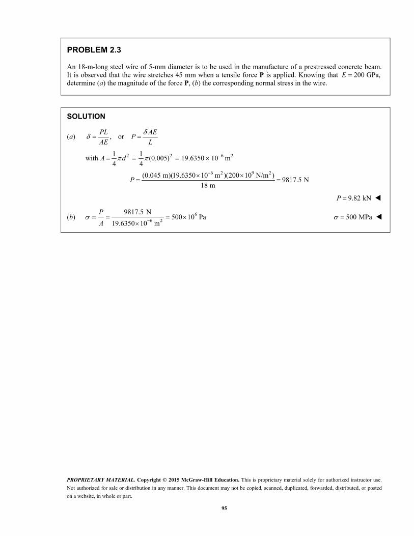
PROBLEM 2.3
An 18-m-long steel wire of 5-mm diameter is to be used in the manufacture of a prestressed concrete beam. It is observed that the wire stretches 45 mm when a tensile force P is applied. Knowing that 200 GPa,E determine (a) the magnitude of the force P, (b) the corresponding normal stress in the wire.
SOLUTION
(a) , orPL AE
PAE L
with 2 2 6 21 1(0.005) 19.6350 10 m
4 4 A d
6 2 9 2(0.045 m)(19.6350 10 m )(200 10 N/m )
9817.5 N18 m
P
9.82 kNP
(b) 66 2
9817.5 N500 10 Pa
19.6350 10 m
P
A 500 MPa

Full file at https://fratstock.eu
PROPRIETARY MATERIAL. Copyright © 2015 McGraw-Hill Education. This is proprietary material solely for authorized instructor use.
Not authorized for sale or distribution in any manner. This document may not be copied, scanned, duplicated, forwarded, distributed, or posted
on a website, in whole or part.
96
PROBLEM 2.4
Two gage marks are placed exactly 250 mm apart on a 12-mm-diameter aluminum rod with E = 73 GPa and an ultimate strength of 140 MPa. Knowing that the distance between the gage marks is 250.28 mm after a load is applied, determine (a) the stress in the rod, (b) the factor of safety.
SOLUTION
(a) 0L L
250.28 mm 250 mm
0.28 mm
0
L
0.28 mm
250 mm
41.11643 10
E
9 4(73 10 Pa)(1.11643 10 )
78.1760 10 Pa
81.8 MPa
(b) F.S. u
140 MPa
81.760 MPa
1.71233 F.S. 1.712

Full file at https://fratstock.eu
PROPRIETARY MATERIAL. Copyright © 2015 McGraw-Hill Education. This is proprietary material solely for authorized instructor use.
Not authorized for sale or distribution in any manner. This document may not be copied, scanned, duplicated, forwarded, distributed, or posted
on a website, in whole or part.
97
PROBLEM 2.5
An aluminum pipe must not stretch more than 0.05 in. when it is subjected to a tensile load. Knowing that 610.1 10E psi and that the maximum allowable normal stress is 14 ksi, determine (a) the maximum
allowable length of the pipe, (b) the required area of the pipe if the tensile load is 127.5 kips.
SOLUTION
(a) PL
AE
Thus, 6
3
(10.1 10 ) (0.05)
14 10
EA EL
P
36.1 in.L
(b) P
A
Thus, 3
3
127.5 10
14 10
PA
29.11 inA

Full file at https://fratstock.eu
PROPRIETARY MATERIAL. Copyright © 2015 McGraw-Hill Education. This is proprietary material solely for authorized instructor use.
Not authorized for sale or distribution in any manner. This document may not be copied, scanned, duplicated, forwarded, distributed, or posted
on a website, in whole or part.
98
PROBLEM 2.6
A control rod made of yellow brass must not stretch more than 3 mm when the tension in the wire is 4 kN. Knowing that E = 105 GPa and that the maximum allowable normal stress is 180 MPa, determine (a) the smallest diameter rod that should be used, (b) the corresponding maximum length of the rod.
SOLUTION
(a) 2
;4
P d
AA
Substituting, we have
2
3
6
3
4
4
4(4 10 N)
(180 10 Pa)
5.3192 10 m
P Pd
d
d
d
5.32 mmd
(b) ; EL
Substituting, we have
E
E LL
9 3
6
(105 10 Pa) (3 10 m)
(180 10 Pa)
L 1.750 mL

Full file at https://fratstock.eu
PROPRIETARY MATERIAL. Copyright © 2015 McGraw-Hill Education. This is proprietary material solely for authorized instructor use.
Not authorized for sale or distribution in any manner. This document may not be copied, scanned, duplicated, forwarded, distributed, or posted
on a website, in whole or part.
99
PROBLEM 2.7
A steel control rod is 5.5 ft long and must not stretch more than 0.04 in. when a 2-kip tensile load is applied to it. Knowing that 629 10 psi,E determine (a) the smallest diameter rod that should be used, (b) the corresponding normal stress caused by the load.
SOLUTION
(a) 6
(2000 lb) (5.5 12 in.)0.04 in.
(29 10 psi):
PL
AE A
2 210.113793 in
4A d
0.38063 in.d 0.381 in.d
(b) 2
2000 lb17575.8 psi
0.113793 in
P
A 17.58 ksi

Full file at https://fratstock.eu
PROPRIETARY MATERIAL. Copyright © 2015 McGraw-Hill Education. This is proprietary material solely for authorized instructor use.
Not authorized for sale or distribution in any manner. This document may not be copied, scanned, duplicated, forwarded, distributed, or posted
on a website, in whole or part.
100
PROBLEM 2.8
A cast-iron tube is used to support a compressive load. Knowing that 610 10 E psi and that the maximum allowable change in length is 0.025%, determine (a) the maximum normal stress in the tube, (b) the minimum wall thickness for a load of 1600 lb if the outside diameter of the tube is 2.0 in.
SOLUTION
(a) 0.00025100L
; EL
EL
6(10 10 psi)(0.00025)
32.50 10 psi
2.50 ksi
(b) 23
1600 lb; 0.64 in
2.50 10 psi
P P
AA
2 2
4
o iA d d
2 2 4
i o
Ad d
2
2 2 24(0.64 in )(2.0 in.) 3.1851 in
id
1.78469 in.id
1 1
( ) (2.0 in. 1.78469 in.)2 2
o it d d
0.107655 in.t
0.1077t

Full file at https://fratstock.eu
PROPRIETARY MATERIAL. Copyright © 2015 McGraw-Hill Education. This is proprietary material solely for authorized instructor use.
Not authorized for sale or distribution in any manner. This document may not be copied, scanned, duplicated, forwarded, distributed, or posted
on a website, in whole or part.
101
PROBLEM 2.9
A 4-m-long steel rod must not stretch more than 3 mm and the normal stress must not exceed 150 MPa when the rod is subjected to a 10-kN axial load. Knowing that 200 GPa,E determine the required diameter of the rod.
SOLUTION
4 mL
3 6
9 3
3 10 m, 150 10 Pa
200 10 Pa, 10 10 NE P
Stress:
36 2 2
6
10 10 N66.667 10 m 66.667 mm
150 10 Pa
P
A
PA
Deformation:
36 2 2
9 3
(10 10 )(4)66.667 10 m 66.667 mm
(200 10 )(3 10 )
PL
AE
PLA
E
The larger value of A governs: 266.667 mmA
2 4 4(66.667)
4
AA d d
9.21 mmd

Full file at https://fratstock.eu
PROPRIETARY MATERIAL. Copyright © 2015 McGraw-Hill Education. This is proprietary material solely for authorized instructor use.
Not authorized for sale or distribution in any manner. This document may not be copied, scanned, duplicated, forwarded, distributed, or posted
on a website, in whole or part.
102
PROBLEM 2.10
A nylon thread is to be subjected to a 10-N tension. Knowing that 3.2E GPa, that the maximum allowable normal stress is 40 MPa, and that the length of the thread must not increase by more than 1%, determine the required diameter of the thread.
SOLUTION
Stress criterion:
6
9 26
92 6
40 MPa 40 10 Pa 10 N
10 N: 250 10 m
40 10 Pa
250 10: 2 2 564.19 10 m
4
P
P PA
A
AA d d
0.564 mmd
Elongation criterion:
1% 0.01
:
LPL
AE
99 2
96 2
/ 10 N/3.2 10 Pa312.5 10 m
/ 0.01
312.5 102 2 630.78 10 m
P EA
L
Ad
0.631 mmd
The required diameter is the larger value: 0.631 mmd

Full file at https://fratstock.eu
PROPRIETARY MATERIAL. Copyright © 2015 McGraw-Hill Education. This is proprietary material solely for authorized instructor use.
Not authorized for sale or distribution in any manner. This document may not be copied, scanned, duplicated, forwarded, distributed, or posted
on a website, in whole or part.
103
PROBLEM 2.11
A block of 10-in. length and 1.8 × 1.6-in. cross section is to support a centric compressive load P. The material to be used is a bronze for which E 14 × 106 psi. Determine the largest load that can be applied, knowing that the normal stress must not exceed 18 ksi and that the decrease in length of the block should be at most 0.12% of its original length.
SOLUTION
Considering allowable stress, 318 ksi or 18 10 psi
Cross-sectional area: 2(1.8 in.)(1.6 in.) 2.880 in A
3 2
4
(18 10 psi)(2.880 in )
5.1840 10 lb
or 51.840 kips
PP A
A
Considering allowable deformation, 0.12% or 0.0012 in.L
2 6
4
(2.880 in )(14 10 psi)(0.0012 in.)
4.8384 10 lb
or 48.384 kips
PLP AE
AE L
P
The smaller value for P resulting from the required deformation criteria governs.
48.4 kips

Full file at https://fratstock.eu
PROPRIETARY MATERIAL. Copyright © 2015 McGraw-Hill Education. This is proprietary material solely for authorized instructor use.
Not authorized for sale or distribution in any manner. This document may not be copied, scanned, duplicated, forwarded, distributed, or posted
on a website, in whole or part.
104
PROBLEM 2.12
A square yellow-brass bar must not stretch more than 2.5 mm when it is subjected to a tensile load. Knowing that 105E GPa and that the allowable tensile strength is 180 MPa, determine (a) the maximum allowable length of the bar, (b) the required dimensions of the cross section if the tensile load is 40 kN.
SOLUTION
6 3
9 3
180 10 Pa 40 10 N
105 10 Pa 2.5 10 m
P
E
(a)
9 3
6
(105 10 )(2.5 10 )1.45833 m
180 10
PL L
AE E
EL
1.458 mL
(b)
36 2 2
6
40 10222.22 10 m 222.22 mm
180 10
P
A
PA
2 222.22A a a A 14.91 mma

Full file at https://fratstock.eu
PROPRIETARY MATERIAL. Copyright © 2015 McGraw-Hill Education. This is proprietary material solely for authorized instructor use.
Not authorized for sale or distribution in any manner. This document may not be copied, scanned, duplicated, forwarded, distributed, or posted
on a website, in whole or part.
105
72 in.
54 in.
72 in.
B
A
C
D
P � 130 kips
PROBLEM 2.13
Rod BD is made of steel 6( 29 10 psi)E and is used to brace the axially compressed member ABC. The maximum force that can be developed in member BD is 0.02P. If the stress must not exceed 18 ksi and the maximum change in length of BD must not exceed 0.001 times the length of ABC, determine the smallest-diameter rod that can be used for member BD.
SOLUTION
30.02 (0.02)(130) 2.6 kips 2.6 10 lb BDF P
Considering stress, 318 ksi 18 10 psi
22.60.14444 in
18 BD BDF F
AA
Considering deformation, (0.001)(144) 0.144 in.
3
26
(2.6 10 )(54)0.03362 in
(29 10 )(0.144)
BD BD BD BDF L F LA
AE E
Larger area governs. 20.14444 inA
2 4 (4)(0.14444)
4
A
A d d 0.429 in.d

Full file at https://fratstock.eu
PROPRIETARY MATERIAL. Copyright © 2015 McGraw-Hill Education. This is proprietary material solely for authorized instructor use.
Not authorized for sale or distribution in any manner. This document may not be copied, scanned, duplicated, forwarded, distributed, or posted
on a website, in whole or part.
106
3.5 m
4.0 m
2.5 m
B
A C
P
PROBLEM 2.14
The 4-mm-diameter cable BC is made of a steel with 200 GPa.E Knowing that the maximum stress in the cable must not exceed 190 MPa and that the elongation of the cable must not exceed 6 mm, find the maximum load P that can be applied as shown.
SOLUTION
2 26 4 7.2111 m BCL
Use bar AB as a free body.
4
0: 3.5 (6) 07.2111
0.9509
A BC
BC
M P F
P F
Considering allowable stress, 6190 10 Pa
2 2 6 2
6 6 3
(0.004) 12.566 10 m4 4
(190 10 )(12.566 10 ) 2.388 10 N
BCBC
A d
FF A
A
Considering allowable elongation, 36 10 m
6 9 3
3(12.566 10 )(200 10 )(6 10 )2.091 10 N
7.2111BC BC
BCBC
F L AEF
AE L
Smaller value governs. 32.091 10 NBCF
3 30.9509 (0.9509)(2.091 10 ) 1.988 10 NBCP F 1.988 kNP

Full file at https://fratstock.eu
PROPRIETARY MATERIAL. Copyright © 2015 McGraw-Hill Education. This is proprietary material solely for authorized instructor use.
Not authorized for sale or distribution in any manner. This document may not be copied, scanned, duplicated, forwarded, distributed, or posted
on a website, in whole or part.
107
P
1.25-in. diameter
4 ft3 ft
d
A
BC
PROBLEM 2.15
A single axial load of magnitude P = 15 kips is applied at end C of the steel rod ABC. Knowing that E = 30 × 106 psi, determine the diameter d of portion BC for which the deflection of point C will be 0.05 in.
SOLUTION
iC
i i AB BC
PL PL PL
A E AE AE
4 ft 48 in.; 3 ft 36 in.AB BCL L
2 2
2(1.25 in.)1.22718 in
4 4 AB
dA
Substituting, we have
3
6 2
15 10 lb 48 in. 36 in.0.05 in.
30 10 psi 1.22718 in
BCA
20.59127 inBCA
2
4BCd
A
4
BCAor d
24(0.59127 in )
d
0.86766 in.d
0.868 in.d

Full file at https://fratstock.eu
PROPRIETARY MATERIAL. Copyright © 2015 McGraw-Hill Education. This is proprietary material solely for authorized instructor use.
Not authorized for sale or distribution in any manner. This document may not be copied, scanned, duplicated, forwarded, distributed, or posted
on a website, in whole or part.
108
36 mm 28 mm
25 mm
250 mm
PROBLEM 2.16
A 250-mm-long aluminum tube ( 70 GPa)E of 36-mm outer diameter and 28-mm inner diameter can be closed at both ends by means of single-threaded screw-on covers of 1.5-mm pitch. With one cover screwed on tight, a solid brass rod ( 105 GPa)E of 25-mm diameter is placed inside the tube and the second cover is screwed on. Since the rod is slightly longer than the tube, it is observed that the cover must be forced against the rod by rotating it one-quarter of a turn before it can be tightly closed. Determine (a) the average normal stress in the tube and in the rod, (b) the deformations of the tube and of the rod.
SOLUTION
2 2 2 2 2 6 2tube
2 2 2 6 2rod
9tube 9 6
tube tube
rod 6rod rod
( ) (36 28 ) 402.12 mm 402.12 10 m4 4
(25) 490.87 mm 490.87 10 m4 4
(0.250)8.8815 10
(70 10 )(402.12 10 )
(0.250)
(105 10 )(490.87 1
o iA d d
A d
PL PP
E A
PL P
E A9
6
* 6
* *tube rod tube rod
9 9 6
33
9
4.8505 100 )
1turn 1.5 mm 0.375 mm 375 10 m
4
or
8.8815 10 4.8505 10 375 10
0.375 1027.308 10 N
(8.8815 4.8505)(10 )
P
P P
P
(a) 3
6tube 6
tube
27.308 1067.9 10 Pa
402.12 10
P
A tube 67.9 MPa
3
6rod 6
rod
27.308 1055.6 10 Pa
490.87 10
P
A rod 55.6 MPa
(b) 9 3 6tube (8.8815 10 )(27.308 10 ) 242.5 10 m tube 0.243 mm
9 3 6rod (4.8505 10 )(27.308 10 ) 132.5 10 m rod 0.1325 mm

Full file at https://fratstock.eu
PROPRIETARY MATERIAL. Copyright © 2015 McGraw-Hill Education. This is proprietary material solely for authorized instructor use.
Not authorized for sale or distribution in any manner. This document may not be copied, scanned, duplicated, forwarded, distributed, or posted
on a website, in whole or part.
109
P 5 350 lbA B C D
1 in. 1 in.
1.6 in. 2 in.
0.4 in.
1.6 in.
P 5 350 lb
PROBLEM 2.17
The specimen shown has been cut from a 14 -in.-thick sheet
of vinyl (E = 0.45 × 10⁶ psi) and is subjected to a 350-lb tensile load. Determine (a) the total deformation of the specimen, (b) the deformation of its central portion BC.
SOLUTION
36
(350 lb)(1.6 in.)4.9778 10 in.
(0.45 10 psi)(1 in.)(0.25 in.)
AB
ABAB
PL
EA
36
(350 lb)(2 in.)15.5556 10 in.
(0.45 10 psi)(0.4 in.)(0.25 in.)
BC
BCBC
PL
EA
34.9778 10 in. CD AB
(a) Total deformation:
AB BC CD
325.511 10 in.
325.5 10 in.
(b) Deformation of portion BC :
315.56 10 in.BC

Full file at https://fratstock.eu
PROPRIETARY MATERIAL. Copyright © 2015 McGraw-Hill Education. This is proprietary material solely for authorized instructor use.
Not authorized for sale or distribution in any manner. This document may not be copied, scanned, duplicated, forwarded, distributed, or posted
on a website, in whole or part.
110
375 mm
1 mm
C
D A
B
P
PROBLEM 2.18
The brass tube ( 105 GPa)AB E has a cross-sectional area of 140 mm2 and is fitted with a plug at A. The tube is attached at B to a rigid plate that is itself attached at C to the bottom of an aluminum cylinder ( 72 GPa)E with a cross-sectional area of 250 mm2. The cylinder is then hung from a support at D. In order to close the cylinder, the plug must move down through 1 mm. Determine the force P that must be applied to the cylinder.
SOLUTION
Shortening of brass tube AB:
2 6 2
9
99 6
375 1 376 mm 0.376 m 140 mm 140 10 m
105 10 Pa
(0.376)25.578 10
(105 10 )(140 10 )
AB AB
AB
ABAB
AB AB
L A
E
PL PP
E A
Lengthening of aluminum cylinder CD:
2 6 2 9
99 6
0.375 m 250 mm 250 10 m 72 10 Pa
(0.375)20.833 10
(72 10 )(250 10 )
CD CD CD
CDCD
CD CD
L A E
PL PP
E A
Total deflection: A AB CD where 0.001 mA
9 90.001 (25.578 10 20.833 10 ) P
321.547 10 NP 21.5 kNP

Full file at https://fratstock.eu
PROPRIETARY MATERIAL. Copyright © 2015 McGraw-Hill Education. This is proprietary material solely for authorized instructor use.
Not authorized for sale or distribution in any manner. This document may not be copied, scanned, duplicated, forwarded, distributed, or posted
on a website, in whole or part.
111
0.4 m
0.5 m
P
Q
20-mm diameter
60-mm diameter
A
B
C
PROBLEM 2.19
Both portions of the rod ABC are made of an aluminum for which 70 GPa.E Knowing that the magnitude of P is 4 kN, determine (a) the value of Q so that the deflection at A is zero, (b) the corresponding deflection of B.
SOLUTION
(a) 2 2 6 2(0.020) 314.16 10 m4 4AB ABA d
2 2 3 2(0.060) 2.8274 10 m4 4BC BCA d
Force in member AB is P tension.
Elongation:
3
69 6
(4 10 )(0.4)72.756 10 m
(70 10 )(314.16 10 )
AB
ABAB
PL
EA
Force in member BC is Q P compression.
Shortening:
99 3
( ) ( )(0.5)2.5263 10 ( )
(70 10 )(2.8274 10 )
BC
BCBC
Q P L Q PQ P
EA
For zero deflection at A, BC AB
9 6 32.5263 10 ( ) 72.756 10 28.8 10 N Q P Q P
3 3 328.3 10 4 10 32.8 10 NQ 32.8 kNQ
(b) 672.756 10 mAB BC B 0.0728 mm AB

Full file at https://fratstock.eu
PROPRIETARY MATERIAL. Copyright © 2015 McGraw-Hill Education. This is proprietary material solely for authorized instructor use.
Not authorized for sale or distribution in any manner. This document may not be copied, scanned, duplicated, forwarded, distributed, or posted
on a website, in whole or part.
112
0.4 m
0.5 m
P
Q
20-mm diameter
60-mm diameter
A
B
C
PROBLEM 2.20
The rod ABC is made of an aluminum for which 70 GPa.E Knowing that 6 kNP and 42 kN,Q determine the deflection of (a) point A, (b) point B.
SOLUTION
2 2 6 2
2 2 3 2
(0.020) 314.16 10 m4 4
(0.060) 2.8274 10 m4 4
AB AB
BC BC
A d
A d
3
3 3 3
6 10 N
6 10 42 10 36 10 N
0.4 m 0.5 m
AB
BC
AB BC
P P
P P Q
L L
36
6 9
36
3 9
(6 10 )(0.4)109.135 10 m
(314.16 10 )(70 10 )
( 36 10 )(0.5)90.947 10 m
(2.8274 10 )(70 10 )
AB ABAB
AB A
BC BCBC
BC
P L
A E
P L
A E
(a) 6 6 6109.135 10 90.947 10 m 18.19 10 mA AB BC 0.01819 mmA
(b) 690.9 10 m 0.0909 mmB BC or 0.0909 mm B

Full file at https://fratstock.eu
PROPRIETARY MATERIAL. Copyright © 2015 McGraw-Hill Education. This is proprietary material solely for authorized instructor use.
Not authorized for sale or distribution in any manner. This document may not be copied, scanned, duplicated, forwarded, distributed, or posted
on a website, in whole or part.
113
4.0 m 4.0 m
2.5 mD CA
B
228 kN
PROBLEM 2.21
For the steel truss ( 200 GPa)E and loading shown, determine the deformations of the members AB and AD, knowing that their cross-sectional areas are 2400 mm2 and 1800 mm2, respectively.
SOLUTION
Statics: Reactions are 114 kN upward at A and C.
Member BD is a zero force member.
2 24.0 2.5 4.717 m ABL
Use joint A as a free body.
2.5
0 : 114 04.717y ABF F
215.10 kNABF
4
0 : 04.717x AD ABF F F
(4)( 215.10)
182.4 kN4.717ADF
Member AB:
3
9 6
( 215.10 10 )(4.717)
(200 10 )(2400 10 )AB AB
ABAB
F L
EA
32.11 10 m 2.11 mm AB
Member AD: 3
9 6
(182.4 10 )(4.0)
(200 10 )(1800 10 )AD AD
ADAD
F L
EA
32.03 10 m 2.03 mm AD

Full file at https://fratstock.eu
PROPRIETARY MATERIAL. Copyright © 2015 McGraw-Hill Education. This is proprietary material solely for authorized instructor use.
Not authorized for sale or distribution in any manner. This document may not be copied, scanned, duplicated, forwarded, distributed, or posted
on a website, in whole or part.
114
15 ft
8 ft
8 ft
8 ft
D
C
F
E
G
A
B
30 kips
30 kips
30 kips
PROBLEM 2.22
For the steel truss 6( 29 10 psi)E and loading shown, determine the deformations of the members BD and DE, knowing that their cross-sectional areas are 2 in2 and 3 in2, respectively.
SOLUTION
Free body: Portion ABC of truss
0 : (15 ft) (30 kips)(8 ft) (30 kips)(16 ft) 0
48.0 kipsE BD
BD
M F
F
Free body: Portion ABEC of truss
0 : 30 kips 30 kips 0
60.0 kips
x DE
DE
F F
F
3
2 6
( 48.0 10 lb)(8 12 in.)
(2 in )(29 10 psi)
BD
PL
AE 379.4 10 in. BD
3
2 6
( 60.0 10 lb)(15 12 in.)
(3 in )(29 10 psi)
DE
PL
AE 3124.1 10 in. DE

Full file at https://fratstock.eu
PROPRIETARY MATERIAL. Copyright © 2015 McGraw-Hill Education. This is proprietary material solely for authorized instructor use.
Not authorized for sale or distribution in any manner. This document may not be copied, scanned, duplicated, forwarded, distributed, or posted
on a website, in whole or part.
115
6 ft 6 ft
5 ft
C
D EA
B
28 kips 54 kips
PROBLEM 2.23
Members AB and BC are made of steel 6( 29 10 psi)E with cross-sectional areas of 0.80 in2 and 0.64 in2, respectively. For the loading shown, determine the elongation of (a) member AB, (b) member BC.
SOLUTION
(a) 2 26 5 7.810 ft 93.72 in. ABL
Use joint A as a free body.
3
50: 28 0
7.810
43.74 kip 43.74 10 lb
y AB
AB
F F
F
3
6
(43.74 10 )(93.72)
(29 10 )(0.80)
AB ABAB
AB
F L
EA 0.1767 in. AB
(b) Use joint B as a free body.
3
60: 0
7.810(6)(43.74)
33.60 kip 33.60 10 lb7.810
x BC AB
BC
F F F
F
3
6
(33.60 10 )(72)
(29 10 )(0.64)
BC BCBC
BC
F L
EA 0.1304 in.BC

Full file at https://fratstock.eu
PROPRIETARY MATERIAL. Copyright © 2015 McGraw-Hill Education. This is proprietary material solely for authorized instructor use.
Not authorized for sale or distribution in any manner. This document may not be copied, scanned, duplicated, forwarded, distributed, or posted
on a website, in whole or part.
116
6 m
5 m
C
DA
B
P
PROBLEM 2.24
The steel frame ( 200 GPa)E shown has a diagonal brace BD with an area of 1920 mm2. Determine the largest allowable load P if the change in length of member BD is not to exceed 1.6 mm.
SOLUTION
3 2 6 2
2 2 9
9 6 3
3
1.6 10 m, 1920 mm 1920 10 m
5 6 7.810 m, 200 10 Pa
(200 10 )(1920 10 )(1.6 10 )
7.81
78.67 10 N
BD BD
BD BD
BD BDBD
BD BD
BD BD BDBD
BD
A
L E
F L
E A
E AF
L
Use joint B as a free body. 0:xF
50
7.810 BDF P
3
3
5 (5)(78.67 10 )
7.810 7.810
50.4 10 N
BDP F
50.4 kNP

Full file at https://fratstock.eu
PROPRIETARY MATERIAL. Copyright © 2015 McGraw-Hill Education. This is proprietary material solely for authorized instructor use.
Not authorized for sale or distribution in any manner. This document may not be copied, scanned, duplicated, forwarded, distributed, or posted
on a website, in whole or part.
117
P
125 mm225 mm
225 mm
150 mm
E
D
A B
C
PROBLEM 2.25
Link BD is made of brass ( 105 GPa)E and has a cross-sectional area of 240 mm2. Link CE is made of aluminum ( 72 GPa)E and has a cross-sectional area of 300 mm2. Knowing that they support rigid member ABC, determine the maximum force P that can be applied vertically at point A if the deflection of A is not to exceed 0.35 mm.
SOLUTION
Free body member AC:
0: 0.350 0.225 0
1.55556
C BD
BD
M P F
F P
0: 0.125 0.225 0
0.55556
B CE
CE
M P F
F P
99 6
99 6
(1.55556 )(0.225)13.8889 10
(105 10 )(240 10 )
(0.55556 )(0.150)3.8581 10
(72 10 )(300 10 )
BD BDB BD
BD BD
CE CEC CE
CE CE
F L PP
E A
F L PP
E A
Deformation Diagram:
From the deformation diagram,
Slope: 9
917.7470 1078.876 10
0.225
B C
BC
PP
L
9 9
9
13.8889 10 (0.125)(78.876 10 )
23.748 10
A B ABL
P P
P
Apply displacement limit. 3 90.35 10 m 23.748 10 A P
314.7381 10 NP 14.74 kNP

Full file at https://fratstock.eu
PROPRIETARY MATERIAL. Copyright © 2015 McGraw-Hill Education. This is proprietary material solely for authorized instructor use.
Not authorized for sale or distribution in any manner. This document may not be copied, scanned, duplicated, forwarded, distributed, or posted
on a website, in whole or part.
118
260 mm
18 kN 18 kN240 mm
180 mmC
D
E
F
A
B
PROBLEM 2.26
Members ABC and DEF are joined with steel links (E 200 GPa). Each of the links is made of a pair of 25 × 35-mm plates. Determine the change in length of (a) member BE, (b) member CF.
SOLUTION
Free body diagram of Member ABC:
0: BM
(0.26 m)(18 kN) (0.18 m) 0 CFF
26.0 kNCFF
0: xF
18 kN 26.0 kN 0 BEF
44.0 kN BEF
Area for link made of two plates:
3 22(0.025 m)(0.035 m) 1.750 10 m A
(a) 3
9 3 2
6
( 44.0 10 N)(0.240 m)
(200 10 Pa)(1.75 10 m )
30.171 10 m
BEBE
F L
EA
0.0302 mmBE
(b) 3
9 3 2
6
(26.0 10 N)(0.240 m)
(200 10 Pa)(1.75 10 m )
17.8286 10 m
BFCF
F L
EA
0.01783 mmCF

Full file at https://fratstock.eu
PROPRIETARY MATERIAL. Copyright © 2015 McGraw-Hill Education. This is proprietary material solely for authorized instructor use.
Not authorized for sale or distribution in any manner. This document may not be copied, scanned, duplicated, forwarded, distributed, or posted
on a website, in whole or part.
119
P = 1 kip
10 in.22 in.
18 in.
A
E
D
B C
PROBLEM 2.27
Each of the links AB and CD is made of aluminum 6( 10.9 10 psi) E and has a cross-sectional area of 0.2 in2. Knowing that they support the rigid member BC, determine the deflection of point E.
SOLUTION
Free body BC:
30: (32) (22) (1 10 ) 0
687.5 lb
C AB
AB
M F
F
30: 687.5 1 10 0
312.5 lb
y CD
CD
F F
F
36
36
(687.5)(18)5.6766 10 in.
(10.9 10 )(0.2)
(312.5)(18)2.5803 10 in.
(10.9 10 )(0.2)
AB ABAB B
CD CDCD C
F L
EA
F L
EA
Deformation diagram:
3
6
3.0963 10Slope
32
96.759 10 rad
B C
BCL
3 6
3
2.5803 10 (22)(96.759 10 )
4.7090 10 in.
E C ECL
34.71 10 in.E

Full file at https://fratstock.eu
PROPRIETARY MATERIAL. Copyright © 2015 McGraw-Hill Education. This is proprietary material solely for authorized instructor use.
Not authorized for sale or distribution in any manner. This document may not be copied, scanned, duplicated, forwarded, distributed, or posted
on a website, in whole or part.
120
12.5 in.
D
CA
x
B50 lb
16 in.4 in.
E116 in.
PROBLEM 2.28
The length of the 332
-in.-diameter steel wire CD has been adjusted so that with no load applied, a gap of 1
16in. exists between the end B of the rigid
beam ACB and a contact point E. Knowing that 629 10 psi,E determine where a 50-lb block should be placed on the beam in order to cause contact between B and E.
SOLUTION
Rigid beam ACB rotates through angle to close gap.
31/163.125 10 rad
20
Point C moves downward.
3 3
3
22 3 2
4 4(3.125 10 ) 12.5 10 in.
12.5 10 in.
36.9029 10 in
4 32
C
CD C
CD
CD CDCD
CD
A dd
F L
EA
6 3 3(29 10 )(6.9029 10 )(12.5 10 )
12.5
200.18 lb
CD CDCD
CD
EAF
L
Free body ACB:
0: 4 (50)(20 ) 0 A CDM F x
(4)(200.18)20 16.0144
503.9856 in.
x
x
For contact, 3.99 in.x