BED INTERCONNECTION TECHNICAL REQUIREMENTS · PDF filerequirement of ANSI C84.1-1995 Range A....
12
BED INTERCONNECTION TECHNICAL REQUIREMENTS By Enis Šehović, P.E. 2/11/2016 Revised 5/19/2016
Transcript of BED INTERCONNECTION TECHNICAL REQUIREMENTS · PDF filerequirement of ANSI C84.1-1995 Range A....

BED INTERCONNECTION TECHNICAL REQUIREMENTS
By
Enis Šehović, P.E.
2/11/2016
Revised 5/19/2016

1
A. TABLE OF CONTENTS B. Interconnection Processes .................................................................................................................... 2
1. Vermont Public Service Board (PSB) Rule 5.500 ............................................................................... 2
2. Vermont Public Service Board (PSB) Rule 5.100 ............................................................................... 2
C. Technical Requirements Goal ............................................................................................................... 3
D. GENERATOR INTERCONNECTION REQUIREMENTS .............................................................................. 3
1. Electrical Code Compliance ........................................................................................................... 3
2. Voltage Level ................................................................................................................................. 4
3. Voltage Flicker ............................................................................................................................... 5
4. Power Factor ................................................................................................................................. 6
5. Frequency ..................................................................................................................................... 6
6. Harmonics ..................................................................................................................................... 7
7. Transformer & Grounding............................................................................................................. 8
8. Dedicated Transformer ................................................................................................................. 8
9. Underwriters Laboratories (UL) & National Electric Code (NEC) requirements ........................... 8
10. Disconnect Switch ..................................................................................................................... 9
11. Circuit Breaker .......................................................................................................................... 9
12. SCADA Control/Indication ......................................................................................................... 9
13. Direct Transfer Trip (DTT) ......................................................................................................... 9
14. Fault Clearing ............................................................................................................................ 9
15. Protective Relays ..................................................................................................................... 10
16. Anti-Islanding .......................................................................................................................... 10
17. Automatic Reclosing ............................................................................................................... 11
18. Protection for Faults on Generator Facilities .......................................................................... 11
19. Other Protection Requirement ............................................................................................... 11
20. Metering ................................................................................................................................. 11
2
BED INTERCONNECTION TECHNICAL REQUIREMENTS
Generation Units
This document provides a set of generic technical requirements to be addressed by small power
producers and owners of co-generation units during the preliminary design of such installations.
As such, they are not to be construed as a final and complete list of requirements which the
applicant for an interconnection agreement will have to satisfy. Other requirements may need to
be met by the owner of the generation project to ensure the final connection design meets all
codes and required studies.
B. INTERCONNECTION PROCESSES
1. Vermont Public Service Board (PSB) Rule 5.500
The Interconnection Procedures and Application form in PSB Rule 5.500 are generally
used for all proposed interconnections of generation resources over 150 KW with BED’s
distribution system that “are not (i) lawfully subject to ISO-NE interconnection rules or
successor rules approved by FERC, or (ii) subject to the Board’s net metering rule (Rule
5.100), for which the interconnection provisions of those rules will govern.”
2. Vermont Public Service Board (PSB) Rule 5.100
PSB net metering Rule 5.100 establishes “the standards and procedures governing
application for, and issuance or revocation of, a certificate of public good for net metering
systems under the provisions of 30 V.S.A §§ 219a, 219b and 248. This rule also
incorporates the technical specifications related to interconnection requirements and safety
standards for net metering systems.” The application form to Rule 5.500 is submitted to
the Public Service Board and also to BED.

3
C. TECHNICAL REQUIREMENTS GOAL
The following minimum technical requirements define operating parameters and
procedures for third-party generation connected in parallel with the Burlington Electric
Department (BED) 13.8 kV distribution system. They were drafted with the intent of:
• ensuring no degradation of electrical service to BED customers;
• ensuring the safety of BED's personnel and contractor working on the distribution
system;
• Protect and minimize the possible damage to the BED’s electrical system and other
customers’ property; and
• Ensure the safety of utility customers and the general public.
Capitalized terms herein shall have the same meaning as ascribed to them in the Generation
Interconnection Agreement. To the extent of any inconsistency between the terms of the
Generation Interconnection Agreement and these Technical Requirements, the terms of the
Generation Interconnection Agreement shall control.
D. GENERATOR INTERCONNECTION REQUIREMENTS
This section defines the minimum technical requirements for the electrical interconnection
between the generation system and BED’s distribution system. The applicant is
responsible for providing protection for the generation system. The generation system
protection is not provided in this Technical requirement. BED doesn’t assume
responsibility for protection of the generation system equipment.
The generation system and the electrical interconnection protection scheme shall
automatically disconnect the generator from BED’s electrical system in the event of a fault
or other system abnormality.
1. Electrical Code Compliance
The generation interconnection applicant shall be responsible for complying with all
applicable local, state, and federal codes such as National Electric Code (NEC), and
National Electrical Safety Code (NESC).
The generation interconnection system and installation shall comply with the latest version
standard of IEEE Std C37.90.1-2002, IEEE Std C37.90.2-1995, IEEE Std 1547, IEEE Std
1547.1, and UL1741.

4
2. Voltage Level
The primary voltage level at the Point of Interconnection shall be continuously monitored.
Note: BED’s nominal distribution system primary voltage is 13.8 kV. The Facility shall
not actively regulate the voltage at the Point of Common Coupling. The Facility shall be
operated in a manner that the voltage levels on BED’s electrical system are in the same
range as if the Facility was not connected to BED’s electrical system. The Facility
installation shall not cause BED’s service at other customer locations to go outside the
requirement of ANSI C84.1-1995 Range A.
The Facility’s interconnection protection shall disconnect the Facility from BED’s
electrical system based on generator size, type, and set points per IEEE Std 1547-2003.
Clearing time is the time between the start of the abnormal condition and the Facility
ceasing to energize BED’s electrical system. For a generator less than or equal to 30 KW
in peak capacity, the voltage set point and clearing time shall be either fixed or field
adjustable. For a generator greater than 30 KW, the voltage set point and clearing time
shall be field adjustable and approved by BED.
Table 1- Interconnection system response to abnormal voltages (IEEE Std 1547-2003)
Voltage Range
(% of base voltagea)
Clearing Time(s)b
V< 50 0.16
50 ≤ V <88
2.00
110 < V < 120
1.00
V ≥ 120
0.16
a) Base voltages are the nominal system voltages stated in ANSI C84.1-1995, Table 1.
b) Generator ≤ 30 KW, maximum clearing times; Generator > 30 KW, default clearing time.
After a voltage disturbance, no reconnection of the Facility shall take place until the
voltage at the Point of Common Coupling is within Range B of ANSI C84.1-1995, Table 1.
The interconnection system shall include a fixed delay of 5 minutes for generator ≤ 30 KW
and an adjustable delay up to 5 minutes for generator > 30 KW that delay reconnection up to
5 minutes after the steady state voltage and frequency are restored to the ranges identified
in Table 1 and Table 2.

5
3. Voltage Flicker
BED has adopted a "point of irritation" for flicker which is dependent upon both the
frequency and magnitude of the flicker. A graphic representation of this standard is shown
in the following figure:
Any voltage flicker at the Point of Common Coupling caused by the generating facility
shall not exceed the limits defined by the “point of irritation” curve shown above identified
in IEEE Std 519-1992 (IEEE Recommended Practices and Requirements for Harmonic
Control in Electric Power Systems). Compliance with the "point of irritation" does not
absolve the generation interconnection applicant from the burden of modifying the
installation should the installation be identified as the source of voltage flicker. Speed
matching of induction generators (within 1%), proper synchronization/voltage matching of
synchronous generators (within 10 electrical degree and a few percent voltage magnitude)
and soft-start of inverters are means to help reduce voltage flicker impacts on distribution
circuits at the moment of interconnection and should be employed to reduce flicker
impacts.
C1. Generation Disconnection Voltage Flicker: A distributed resource shall not cause
more than a 3% change in the primary voltage at the Point of Common Coupling
(PCC) for a 100% loss of its rated output.
C2. Single Phase Generator Voltage Imbalance: Single phase generators shall not
cause a voltage unbalance exceeding 3% on BED’s three phase interconnecting
circuit (ANSI C84.1).

6
4. Power Factor
Generating systems shall be designed to be capable of operating with power factor between
0.95 lagging and 0.95 leading. Generators shall normally be operated near unity power
factor (+/- 0.98) or as mutually agreed upon between BED and Applicant.
5. Frequency
All DG facilities are to operate at a nominal frequency of 60Hz. All DG Facilities are also
responsible to comply with IEEE 1547 and provide two levels of underfrequency
protection and one or more levels of overfrequency protection. Underfrequency set point
and clearing times are not permitted above the curve in Figure 1 in order to comply with
PRC-006-NPCC-1 Requirement 13 on generator underfrequency settings. The Facility
interconnection protection shall disconnect the Facility from the distribution system should
the frequency fall outside the range with clearing time given in Table 2 below (IEEE Std
1547-2003):
7
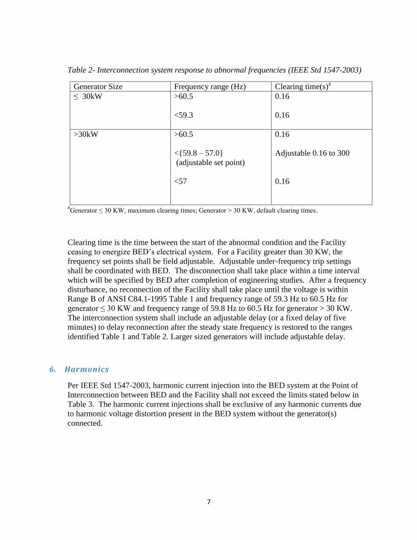
Table 2- Interconnection system response to abnormal frequencies (IEEE Std 1547-2003)
Generator Size Frequency range (Hz) Clearing time(s)a
≤ 30kW >60.5
<59.3
0.16
0.16
>30kW >60.5
<{59.8 – 57.0}
(adjustable set point)
<57
0.16
Adjustable 0.16 to 300
0.16
aGenerator ≤ 30 KW, maximum clearing times; Generator > 30 KW, default clearing times.
Clearing time is the time between the start of the abnormal condition and the Facility
ceasing to energize BED’s electrical system. For a Facility greater than 30 KW, the
frequency set points shall be field adjustable. Adjustable under-frequency trip settings
shall be coordinated with BED. The disconnection shall take place within a time interval
which will be specified by BED after completion of engineering studies. After a frequency
disturbance, no reconnection of the Facility shall take place until the voltage is within
Range B of ANSI C84.1-1995 Table 1 and frequency range of 59.3 Hz to 60.5 Hz for
generator ≤ 30 KW and frequency range of 59.8 Hz to 60.5 Hz for generator > 30 KW.
The interconnection system shall include an adjustable delay (or a fixed delay of five
minutes) to delay reconnection after the steady state frequency is restored to the ranges
identified Table 1 and Table 2. Larger sized generators will include adjustable delay.
6. Harmonics
Per IEEE Std 1547-2003, harmonic current injection into the BED system at the Point of
Interconnection between BED and the Facility shall not exceed the limits stated below in
Table 3. The harmonic current injections shall be exclusive of any harmonic currents due
to harmonic voltage distortion present in the BED system without the generator(s)
connected.

8
Table 3 – Maximum harmonic current distortion in percent of current (I)a
Individual
harmonic
order h (odd
harmonics)b
h<11 11≤ h <17 17≤h<23 23≤h<35 35≤h Total
demand
distortion
(TDD)
Percent (%) 4.0 2.0 1.5 0.6 0.3 5.0
aI = the greater of the BED system maximum load current integrated demand (15 or 30 minutes) without the
generator unit, or the generator (s) unit rated current capacity (transformed to the PCC when a transformer
exists between the generator unit and the PCC (IEEE Std 1547-2003).
bEven harmonics are limited to 25% of the odd harmonic limits above (IEEE Std 1547-2004).
7. Transformer & Grounding
BED’s distribution system is a four wire multi-grounded system. BED’s nominal primary
distribution system voltage is 13.8/7.967 KV. The Facility shall be effectively grounded
where the positive sequence reactance is greater than the zero sequence resistance (X1 >
R0) and the zero sequence reactance is less than three times the positive sequence reactance
(3 X1 > X0). For a three phase Facility connected to BED’s system, the transformer should
be grounded Y-Y.
8. Dedicated Transformer
A dedicated transformer shall be required for all facilities larger than 150kW. A dedicated
transformer shall also be required where the Facility is served from the same transformer as
another customer with sensitive load. In addition, a dedicated transformer or other current-
limiting device shall be installed for any type of Facility installation where the increase in
available short circuit current could adversely impact other customers on the same
secondary circuit.
9. Underwriters Laboratories (UL) & National Electric Code (NEC) requirements
Generation installations using Inverters for interconnection with BED’s electrical system
must use UL listed non-islanding type inverters. The installation of the generator and its
facilities shall be in accordance with applicable NEC requirements.

9
10. Disconnect Switch
The Facility shall provide an approved, visible, lockable, load break disconnect switch
adequate to provide safe working clearance for BED personnel. It shall be accessible to and
available for control by BED personnel at all times. When BED has operated the
disconnect device, the FACILITY SHALL NOT OPERATE the device without prior
approval from the BED representative designated on the tag attached to the disconnect
device. For a facility larger than 150 KW, loadbreak switch capable of responding to an
external trip signal to disconnect the generation equipment from the BED’s electrical
system is required.
11. Circuit Breaker
The Facility shall provide a circuit breaker that is capable of interrupting the maximum
fault current available at the breaker’s location from BED’s electrical system and from the
Facility. The circuit breaker shall be equipped with an approved stored-energy tripping
device. For a facility larger than 500 KW, circuit breaker or recloser capable of responding
to an external trip signal to disconnect the generation equipment from the BED’s electrical
system is required.
12. SCADA Control/Indication
For a Facility larger than 150 KW, a SCADA remote terminal unit shall be supplied by
BED. However, the applicant shall bear the cost of the unit and the installation cost. The
remote terminal unit shall monitor the output of the generator and status points which
indicate the condition of the generator breaker. The unit shall also provide remote tripping
control to BED's dispatcher.
13. Direct Transfer Trip (DTT)
For a large sized Facility, BED may require the installation of a direct transfer trip. The
Applicant shall bear the cost of installing a communication channel between the generator
and a BED substation. This channel will allow remote direct transfer trip by BED. The
communication channel will be detailed by BED after completion of system studies.
14. Fault Clearing
Protection equipment shall be provided to clear all faults. The equipment shall conform to
BED supplied current settings, time-current curves and instantaneous trip settings.
Protection equipment shall meet ANSI C37.90 requirements.

10
15. Protective Relays
Imbedded electronic controls or microprocessor-based relays are suitable in lieu of utility
grade relays for the functions below as long as they satisfy IEEE P929 and UL1741
requirements.
1. Over/Under Voltage Relays: The Facility shall provide utility grade, over voltage
(59) and under voltage (27) relays. These relays shall cover all three phases in a three
phase installation and capable of tripping the circuit breaker when the voltage is not
within the specifications in section 1, above.
2. Over/Under Frequency: The Facility shall provide utility grade, over frequency
(81/O) and under frequency (81/U) relays capable of tripping the circuit breaker when
the frequency is not within the specifications in section 4, above.
3. Unbalanced Fault Protection (Three Phase Generation): The Facility shall provide a
means of detecting an unbalanced fault condition on BED’s electric system using
utility grade relay and associated equipment, and the ability for tripping the
generation circuit breaker when such a fault occurs. The relay should be capable of
detecting one of the following:
a) Magnitude difference between the three phase currents.
b) The presence of negative sequence current.
c) The presence of negative sequence voltage.
d) Overcurrent Relays (50, 51, & 51G)
e) Synchronization Relays
f) Additional Required Relays
16. Anti-Islanding
A Facility shall not be allowed to island with a portion of BED’s distribution system. The
facility anti-islanding protection shall detect the island and cease to energize BED’s
distribution system within two seconds of the formation of an island (IEEE Std 1547). For
a large Facility where the impact of islanding could affect a large number of customers, the
application of transfer trip operation over a communication medium is recommended.

11
17. Automatic Reclosing
The Facility shall be responsible for protecting his/her equipment from the effect of
switching or automatic reclosing of BED’s circuits. BED has at least one aerial
microprocessor recloser on each circuit.
18. Protection for Faults on Generator Facilities
The Facility shall be responsible for providing protection for faults on its generating and
interconnection equipment.
19. Other Protection Requirement
The Facility shall be responsible for protecting its generating and interconnection
equipment in such a manner that BED system outages, short circuits, single phasing
conditions, or other disturbances including zero sequence currents and Ferro-resonant over-
voltage do not damage the Facility’s generating and interconnection equipment.
20. Metering
BED shall install, at the Facility’s expense, bi-directional metering equipment adequate to
accurately measure and record energy received and/or delivered by the Facility to BED’s
electric system. The installed metering arrangement, including telephone line connection to
be supplied by the Facility, must comply with all communication requirements as specified
in the Interconnection Agreement and allow the remote interrogation of the meter by BED.