
BECSys5 Installation and Technical Manualmicro.becs.com/SWM/Manuals/BECSys5/8620013-1.46... ·...
72
Installation and Technical Manual
Transcript of BECSys5 Installation and Technical Manualmicro.becs.com/SWM/Manuals/BECSys5/8620013-1.46... ·...

Installation and Technical Manual


9487 Dielman Rock Island Ind Dr, St. Louis, MO 63132 www.becs.com
Installation and Technical Manual Rev: G12
TABLE OF CONTENTS Warnings......................................................................... 1 Unpacking....................................................................... 2 General Guidelines ......................................................... 2 Firmware Version ........................................................... 2 Environmental Conditions .............................................. 3 Electrical Specifications ................................................. 3 Applicable Sensor Operating Ranges ............................. 4 Section A: Mounting the BECSys5 Controller .............. 5
A – 1: Mounting the Controller ................................. 5 A – 2: Wrapping the Fittings ..................................... 5 A – 3: Assembling the Flow cell ............................... 5 A – 4: Plumbing the Sample Stream .......................... 5 A – 5: Chlorine Sensor Flow Cell .............................. 6 A – 6: Sensor preparations ......................................... 6 A – 7: Opening the Sample Stream Valve ................. 7 A – 8: Plugging in the Sensors................................... 8
Section B: Wiring the BECSys5 Controller................... 9 B – 1: Opening The Cover ......................................... 9 B – 2: Removing the safety shield ............................. 9 B – 3: Supplied Cords ................................................ 9 B – 4: Conduit Connect ........................................... 10 B – 5: Relay Wiring ................................................. 10 B – 6: Relay Expansion Module Wiring .................. 12 B – 7: Flow Switch Wiring ...................................... 13
B – 7.1: Paddlewheel Flow Switch ...................... 13 B – 7.2: Reed Flow Switch .................................. 13
B – 8: Amperometric Probe Wiring ......................... 13 B – 9: Temperature Sensor Wiring .......................... 13 B – 10: Flow Meter Wiring ..................................... 14 B – 11: Conductivity Wiring ................................... 14 B – 12: 4-20mA and Digital Input Wiring ............... 15
B – 12.1: BECSysLS ........................................... 15 B – 12.2: Floats .................................................... 16 B – 12.3: Turbidity sensor ................................... 16 B – 12.4: Pressure Transducer ............................. 16 B – 12.5: Vacuum Transducer ............................. 17 B – 12.6: Murphy Swichgages ............................. 17 B – 12.7: Solid State Autofill Sensor ................... 18 B – 12.8: Total Chlorine Sensor .......................... 19
B – 13: 4-20mA Output Wiring ............................... 19 B – 14: BECSysRPM (Remote Probe Module) ....... 20 B – 15: BECSys Ethernet Board .............................. 21 B – 16: Re-installing the safety shield ..................... 21 B – 17: Fuses ........................................................... 21
Section C: Programming the Controller ...................... 22 C – 1: Adjusting the Display Contrast ..................... 22 C – 2: Security Settings ........................................... 22
C – 2.1: Access Codes and levels ........................ 22 C – 2.2: Setting Access Codes ............................. 22 C – 2.3: Recovering Lost Access Codes .............. 23 C – 2.4: Setting Permissions ................................ 23
C – 3: Navigating the menus ................................... 23
C – 3.1: Common status messages ....................... 23 C – 3.2: The Menu Screens .................................. 24 C – 3.3: The Lock Screen Key ............................. 25
C – 4: Inputs ............................................................. 26 C – 4.1: pH Setup ................................................. 26 C – 4.2: ORP Setup .............................................. 26 C – 4.3: Cl Inputs Setup ....................................... 27
C – 4.3.1: Free Cl Setup .................................... 27 C – 4.3.2: Total Cl Setup ................................... 28 C – 4.3.3: Combined Cl ..................................... 28
C – 4.4: Temperature Setup .................................. 28 C – 4.5: Conductivity/TDS Setup ......................... 29 C – 4.6: Flow Rate Setup ...................................... 29 C – 4.7: pH & Chlorine Inventory Setups ............ 30 C – 4.8: Turbidity ................................................. 31 C – 4.9: Surge Pit Level ....................................... 31 C – 4.10: Pressure & Vacuum Setup .................... 32
C – 4.10.1: Filter Influent Pressure ................... 32 C – 4.10.2: Filter Effluent Pressure .................. 33 C – 4.10.3: Filter Differential Pressure ............. 33 C – 4.10.4: Pump Effluent Pressure ................. 34 C – 4.10.5: Strainer Vacuum ............................ 34 C – 4.10.6: Total Dynamic Head ...................... 35
C – 5: Control Outputs ............................................. 36 C – 5.1: Assign Relays ......................................... 36
C – 5.1.1 - Sanitization feeds ............................. 36 C – 5.1.2 - Other Feeds ...................................... 36
C – 5.2: pH Control .............................................. 37 C – 5.3: Chlorine Control ..................................... 38 C – 5.4: Chlorine Booster Control ........................ 40 C – 5.5: Super Chlorination .................................. 41 C – 5.6: Dechlorination ........................................ 41 C – 5.7: Ozone Control ......................................... 42 C – 5.8: Heater ..................................................... 42 C – 5.9: Autofill ................................................... 43 C – 5.10: TDS Control ......................................... 43 C – 5.11: Sensor Wash ......................................... 43 C – 5.12: Enzyme ................................................. 44 C – 5.13: Polymer ................................................. 44 C – 5.14: UV Turndown ....................................... 44 C – 5.15: Recirculation Pump .............................. 45
C – 5.15.1: VFD Control: .................................. 45 C – 5.16: Alarm Relay .......................................... 46
C – 6: Control Options ............................................. 47 C – 6.1: Flow Restored Feed Delay ...................... 47 C – 6.2: Power Saver ............................................ 47 C – 6.3: pH Lockout ............................................. 47
C – 7: Calculations ................................................... 48 C – 7.1: Enter Parameters ..................................... 48 C – 7.2: LSI Setup ................................................ 48
C – 8: System Configuration .................................... 48 C – 8.1: System Info ............................................. 48
www.becs.com 9487 Dielman Rock Island Ind Dr, St. Louis, MO 63132
Installation and Technical Manual Rev: G12 C – 8.2: Communication ...................................... 48
C – 8.2.1: Direct Baud Rate ............................. 48 C – 8.2.2: Modem Options............................... 48 C – 8.2.3: Ethernet Setup ................................. 48 C – 8.2.4: Call Out Setup ................................. 48 C – 8.2.5: BECSysBW link ............................. 49 C – 8.2.6: BECSys-Online ............................... 50 C – 8.2.7: Modbus ........................................... 50 C – 8.2.8: RS485 Network Setup ..................... 50 C – 8.2.9: Installed Options ............................. 50
C – 8.3: Datalog Frequency ................................. 50 C – 8.4: Date, Time & Units ................................ 50 C – 8.5: Name and Location ................................ 50 C – 8.6: User Setup .............................................. 51 C – 8.7: Factory Defaults ..................................... 51 C – 8.8: Display Options ..................................... 51
C – 9: VFD Turndowns ........................................... 51 C – 10: 4-20mA Outs ............................................... 52 C – 11: Access Menu ............................................... 52
Section D: The Normal Display .................................. 53 D – 1: Inputs and Feeds ........................................... 53 D – 2: Alarms & Status messages ............................ 53
Section E: Using the Face Panel Quick Keys .............. 54 E – 1: The Set Points Key ........................................ 54 E – 2: The Relay Mode Key .................................... 54 E – 3: The Cal Key (calibration) .............................. 55 E – 4: The Reset Fail / Safe Key .............................. 55 E – 5: The Emergency Off Key ............................... 55
Section F: Startup Programming ................................. 56 F – 1: VFD Control .................................................. 56 F – 2: Autofill .......................................................... 57
Section G: Troubleshooting ......................................... 58 G – 1: Calibration Errors ......................................... 58 G – 2: Low Battery Alarm ....................................... 58 G – 3: Chlorine Sensors ........................................... 58
G – 3.1: General Tips........................................... 58 G – 3.2: Free Chlorine ......................................... 58 G – 3.3: Total Chlorine ........................................ 58
Section H: Maintenance ............................................... 59 H – 1: Potentiometric Sensors (pH and ORP) ......... 59 H – 2: Free Chlorine Sensor .................................... 59 H – 3: Total Chlorine Sensor ................................... 60 H – 4: Conductivity Sensor ...................................... 60
Section I: Tables .......................................................... 61 I – 1: Flow Meter K-Factors .................................... 61
Section J: Feed Charts ................................................. 62 J – 1: Spa Feed Charts ............................................. 62 J – 2: Pool Feed Charts ............................................ 63
Section K: Installation Diagrams ................................. 64 K – 1: Pressure Filter Installation ............................ 64 K – 2: Vacuum Filter Installation ............................ 64
Section L: Replacement Parts ...................................... 65 Section M: Warranty ................................................... 67

Page 1 9487 Dielman Rock Island Ind Dr, St. Louis, MO 63132 www.becs.com
Installation and Technical Manual Rev: G12
Warnings Pay particular attention to the following warnings encountered in the pages of the
BECSys5 Installation and Technical Manual:
Warning: Various other warning boxes may be found throughout the manual text.
Caution: Various caution boxes may be found throughout the manual text.

Page 2 www.becs.com 9487 Dielman Rock Island Ind Dr, St. Louis, MO 63132
Installation and Technical Manual Rev: G12
Unpacking Your Shipping package should contain these items: A. The BECSys5 Controller B. ORP Sensor C. pH Sensor D. Temperature Sensor E. Flow cell Kit F. Rotary or Reed flow switch G. This manual (not shown) H. BECSys for Windows Installation CD (not shown) I. Optional sensors (not shown) A B C D E F
General Guidelines Proper installation and use of the BECSys controller depends on the specific needs of the application. Read the manual completely before starting the installation and ensure all guidelines and recommendations are followed. All components should be mounted and the flow cell plumbing installed and pressure tested before wiring the controller. Ensure compliance with all applicable plumbing and electrical codes during the installation as well.
Firmware Version This manual was written for firmware v1.46. If you received newer firmware but did not receive a copy of the manual covering that version of firmware, please contact your distributor.
Warning: The ORP and pH Sensors are very fragile and must be handled with care. The tips of the probes must be kept wet at all times, requiring the wetting caps to remain in place until they are ready to be
installed. The probes must be stored in temperatures above freezing.
Rotary
Reed
or
Caution: The BECSys controller should not be installed where it is accessible to the public.

Page 3 9487 Dielman Rock Island Ind Dr, St. Louis, MO 63132 www.becs.com
Installation and Technical Manual Rev: G12
Environmental Conditions The BECSys5 is housed in a NEMA 4X (IP65) enclosure. It should not be used in explosive environments. The BECSys5 should be mounted so that adequate ventilation is provided around the enclosure, preventing general environmental specifications from being exceeded (see table below).
Environmental Specifications Specification Rating Storage Temperature -40 to 85 Deg C Ambient Operating Temperature -18 to 50 Deg C Ambient Humidity 95% non condensing maximum humidity
Electrical Specifications The BECSys5 may be ordered in either a 115VAC model or a 230VAC model. Following are the electrical specifications for each model:
Controller Ratings 115VAC Model 230VAC Model Voltage: 115VAC 60Hz 230VAC 50Hz Phase: Single Single Current: 12.25 Amps Full Load 12.125 Amps Full Load
(¼ Amp – Controller) (⅛ Amp – Controller) (12 Amps – Relay Outputs: 3A X 4) (12 Amps – Relay Outputs: 3A X 4)
Relay Output Ratings
115VAC Model 230VAC Model Relay 1 (K1) 250VAC (max) – 3 Amps 250VAC (max) – 3 Amps Relay 2 (K2) 250VAC (max) – 3 Amps 250VAC (max) – 3 Amps Relay 3 (K3) 250VAC (max) – 3 Amps 250VAC (max) – 3 Amps Relay 4 (K4) 250VAC (max) – 3 Amps 250VAC (max) – 3 Amps

Page 4 www.becs.com 9487 Dielman Rock Island Ind Dr, St. Louis, MO 63132
Installation and Technical Manual Rev: G12
Applicable Sensor Operating Ranges
Standard Sensors pH 0.0 pH to 14.0 pH ORP -1000mV to 1000mV Temperature 32°F to 212°F (0°C to 100°C) Reed Flow Switch Switch Point (On): 2.0 gpm Rotary Flow Switch Switch Point (On): 1.5 gpm
Optional Sensors Amperometric ppm 0 ppm to 20 ppm Total Chlorine 0 ppm to 20 ppm Pressure Transducer 0 to 100 PSI Vacuum Transducer -14.7 to 85 PSI Vacuum Swichgage 0 – 30 in. HG Pressure Swichgage 0 – 50 PSI Differential Swichgage 0 – 50 PSI Conductivity Sensor 0 – 20,000 micromho Turbidimeter 0 – 20.0 NTU Flowmeter 0 – 655.35 Kgpm

Page 5 9487 Dielman Rock Island Ind Dr, St. Louis, MO 63132 www.becs.com
Installation and Technical Manual Rev: G12
Section A: Mounting the BECSys5 Controller
A – 1: Mounting the Controller The BECSys5 Controller and flow cell are mounted separately. The BECSys5 enclosure should be mounted to the wall with four anchor bolts. To mount the BECSys5 properly, please use the included mounting template and hardware. Drill the holes for the anchors using a 3/16” drill bit. Install the anchors in the wall. Remove the lid from the unit and place the included screws in the four corners of the box. Attach the screws into the anchors. The BECSys5 and flow cell should be mounted in a location that is free from chemical fumes and excessive heat, isolated from electrical interference, and near a power source protected by a ground fault interrupter. The BECSys5 has a NEMA4 weather resistant enclosure but should still be protected if mounted outdoors.
A – 2: Wrapping the Fittings If you are assembling a flow cell, first open the bag of flow cell fittings and wrap each fitting two times around clockwise with Teflon tape.
A – 3: Assembling the Flow cell Assemble the flow cell as shown below:
When installing the pH or ORP sensor, remove the wetting cap, then remove any existing Teflon tape from the sensor threads. Re-wrap the threads with new Teflon tape. Rinse the sensor tip in de-ionized water and install as shown.
A – 4: Plumbing the Sample Stream Install the sample stream; ½-inch tubing is recommended for sample stream pickup and return. Make sure that you tap the supply off the discharge side of the recirculation pump, upstream of the chemical injection points. The sample should be filtered water. Connect the sample stream pickup line to the flow cell and run the sample stream return line from the flow cell to the suction side of the main recirculation pump. Install ½-inch ball valves to allow isolation of the sample lines.
Warning: These sensors should be hand-tightened only. Tools are not necessary for
installing the pH or ORP sensor and will damage the sensor housing.
Page 6 www.becs.com 9487 Dielman Rock Island Ind Dr, St. Louis, MO 63132
Installation and Technical Manual Rev: G12
A – 5: Chlorine Sensor Flow Cell
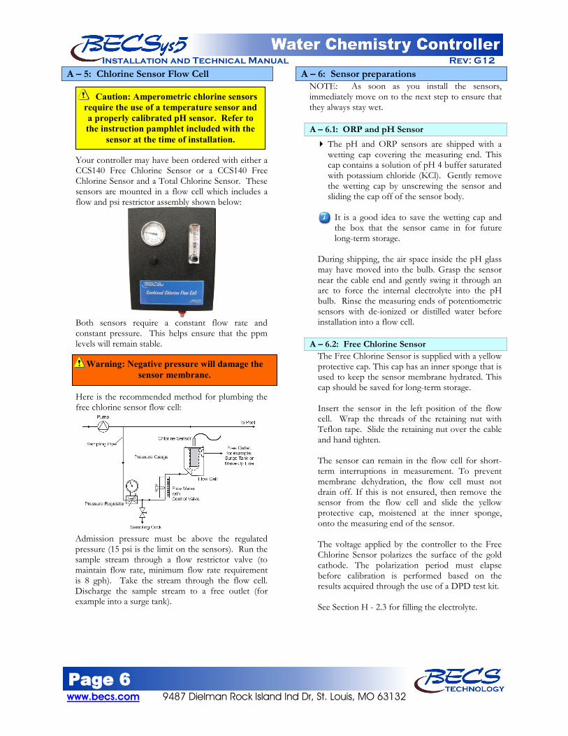
Your controller may have been ordered with either a CCS140 Free Chlorine Sensor or a CCS140 Free Chlorine Sensor and a Total Chlorine Sensor. These sensors are mounted in a flow cell which includes a flow and psi restrictor assembly shown below:
Both sensors require a constant flow rate and constant pressure. This helps ensure that the ppm levels will remain stable.
Here is the recommended method for plumbing the free chlorine sensor flow cell:
Admission pressure must be above the regulated pressure (15 psi is the limit on the sensors). Run the sample stream through a flow restrictor valve (to maintain flow rate, minimum flow rate requirement is 8 gph). Take the stream through the flow cell. Discharge the sample stream to a free outlet (for example into a surge tank).
A – 6: Sensor preparations NOTE: As soon as you install the sensors, immediately move on to the next step to ensure that they always stay wet. A – 6.1: ORP and pH Sensor The pH and ORP sensors are shipped with a
wetting cap covering the measuring end. This cap contains a solution of pH 4 buffer saturated with potassium chloride (KCl). Gently remove the wetting cap by unscrewing the sensor and sliding the cap off of the sensor body.
It is a good idea to save the wetting cap and the box that the sensor came in for future long-term storage.
During shipping, the air space inside the pH glass may have moved into the bulb. Grasp the sensor near the cable end and gently swing it through an arc to force the internal electrolyte into the pH bulb. Rinse the measuring ends of potentiometric sensors with de-ionized or distilled water before installation into a flow cell.
A – 6.2: Free Chlorine Sensor The Free Chlorine Sensor is supplied with a yellow protective cap. This cap has an inner sponge that is used to keep the sensor membrane hydrated. This cap should be saved for long-term storage. Insert the sensor in the left position of the flow cell. Wrap the threads of the retaining nut with Teflon tape. Slide the retaining nut over the cable and hand tighten. The sensor can remain in the flow cell for short-term interruptions in measurement. To prevent membrane dehydration, the flow cell must not drain off. If this is not ensured, then remove the sensor from the flow cell and slide the yellow protective cap, moistened at the inner sponge, onto the measuring end of the sensor. The voltage applied by the controller to the Free Chlorine Sensor polarizes the surface of the gold cathode. The polarization period must elapse before calibration is performed based on the results acquired through the use of a DPD test kit. See Section H - 2.3 for filling the electrolyte.
Caution: Amperometric chlorine sensors require the use of a temperature sensor and a properly calibrated pH sensor. Refer to the instruction pamphlet included with the
sensor at the time of installation.
Warning: Negative pressure will damage the sensor membrane.

Page 7 9487 Dielman Rock Island Ind Dr, St. Louis, MO 63132 www.becs.com
Installation and Technical Manual Rev: G12 A – 6.3: Total Chlorine Sensor
If your controller was ordered with a Total Chlorine Sensor, the following steps must be followed for installation. The Total Chlorine Sensor does not ship with Electrolyte inside the sensor chamber; it must be filled before installation. The lower portion (below the upper band) unscrews. Be sure to lift the hose ring that covers the vent while removing the membrane cap. Fill the membrane cap to the edge with the electrolyte. Make sure there are no bubbles. Insert the sensor into the membrane cap. Slowly screw the membrane cap onto the sensor. Excess electrolyte will escape through a valve in the membrane cap – do not block this valve. Rinse excess electrolyte off with water. Included with the Total Chlorine Sensor are: the Total Chlorine Sensor, the cable, two O-Rings, a probe ring, and the O-Ring retainer and the Probe Nut.
The Probe Ring is installed first. Slide the smaller diameter O-Ring up the sensor body until it rests against the Probe Ring.
Insert the larger diameter O-Ring into the O-Ring retainer. Slide the O-Ring retainer (O-Ring side towards membrane) up against the O-Ring just installed. Insert the complete assembly into the Flow Cell. Wrap the threads of the Probe Nut with Teflon tape. Use the Probe Nut to secure the sensor inside the Flow Cell. The top of the Probe Nut should be at the bottom of the label.
Attach the cable to the top of the Total Chlorine Sensor. The cable and the top of the sensor are keyed. Once the pins are engaged, tighten the cable to the sensor. The voltage applied by the controller to the Total Chlorine Sensor polarizes the surface of the gold cathode. The polarization period (one hour) must elapse before calibrations are performed.
After wiring the sensor to the controller (see section B) and assigning the input, perform the following calibrations:
Two calibrations are required at installation.
1) Shut off the sample stream, drain the flow cell, and then flush and fill it with distilled water. Wait the hour polarization period before calibrating the input, entering 0 ppm for the value. You can calibrate the free chlorine to 0 at this time as well.
2) After the zero point calibration is done, you can open the sample stream valve and wait at least 15 minutes before calibrating again with the results acquired through the use of a DPD test kit. The second calibration should be done with flowing water with at least 2.5 ppm total chlorine.
Warning: The membrane may be damaged if the vent is not opened while removing the
membrane cap.
Warning: Never touch the electrode finger.

Page 8 www.becs.com 9487 Dielman Rock Island Ind Dr, St. Louis, MO 63132
Installation and Technical Manual Rev: G12
A – 7: Opening the Sample Stream Valve Open the sample stream valve and check for leaks. Note the reading on the compound pressure gauge and make sure that it shows a positive and steady pressure. The sample stream should be about 2-20 psi at the flow cell. If this is not the case, then adjust the valves or relocate the point at which the sample stream is connected to the recirculation system. Negative pressure will destroy the sensors. Once you have a positive and steady pressure, open the wet test valve and make sure that it generates a vigorous stream.
A – 8: Plugging in the Sensors Remove the protective covers from the BNCs. Plug the pH sensor into the coded BNC jack and the ORP sensor into the coded BNC jack on the bottom of the BECSys5 controller by twisting them a quarter of a turn. Allow the sensors to rinse in the sample water while you do the wiring (Section B).
Page 9 9487 Dielman Rock Island Ind Dr, St. Louis, MO 63132 www.becs.com
Installation and Technical Manual Rev: G12
Section B: Wiring the BECSys5 Controller
B – 1: Opening The Cover
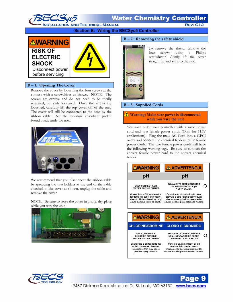
Remove the cover by loosening the four screws at the corners with a screwdriver as shown. NOTE: The screws are captive and do not need to be totally removed, but only loosened. Once the screws are loosened, carefully lift the top cover off of the unit. The cover will still be connected to the base by the ribbon cable. Set the moisture absorbent packet found inside aside for now.
We recommend that you disconnect the ribbon cable by spreading the two holders at the end of the cable attached to the cover as shown, unplug the cable and remove the cover. NOTE: Be sure to store the cover in a safe, dry place while you wire the unit.
B – 2: Removing the safety shield To remove the shield, remove the four screws using a Philips screwdriver. Gently lift the cover straight up and set it to the side.
B – 3: Supplied Cords You may order your controller with a male power cord and two female power cords (Only for 115V applications). Plug the male AC Cord into a GFCI outlet and connect the chemical feeders to the female power cords. The two female power cords will have the following warning tags. Be sure to connect the correct female power cord to the correct chemical feeder.
Warning: Make sure power is disconnected while you wire the unit

Page 10 www.becs.com 9487 Dielman Rock Island Ind Dr, St. Louis, MO 63132
Installation and Technical Manual Rev: G12
B – 4: Conduit Connect You may instead order the controller for conduit connection (For 115V or 230V applications). TB4 is for the Line power coming into the unit.
We recommend using a minimum of 14 gauge stranded wire for the line power. Use of solid wire is strongly discouraged. The black wire goes to L (Line) on the upper level, the white wire to N (Neutral), and the ground wire to the terminal marked Earth Ground. NOTE: The black and white wires are colored brown and blue outside North America.
B – 5: Relay Wiring The BECSys5 has four solid-state relays. From the Factory, the controller is configured to use Relay 1 for the pH Feed and Relay 2 for the ORP/Cl/Br Feed. The rest of the relays are unassigned. Each relay can be powered from either the L (Line) terminal that the controller itself is powered from, or from the common terminals. Relay 1 and 2 share a common (labeled C1 C2), Relays 3 and 4 have their own common labeled C3 and C4 respectfully. As shipped from the factory, all four relays are configured for Line power.
B – 5.1: Externally Powered Wiring
If you wish to use the C (Common) to power a relay (commonly used to interlock feeds with the recirculation pump), you will need to move the black hat jumpers located to the left of each of the solid state relays to their upper position using a pair of long nosed needle nose pliers (shown left). Be careful not to put pressure on the relays as you are slipping between them as you may damage their connections to the board.
B – 5.2: Relay 1
B – 5.2.1: Line Powered Wiring The black wire goes to the R1 position, the white wire goes into any of the unused N (Neutral) positions, and the Earth Ground wire goes to any of the unused Earth Ground positions.
Note: The black and white wires are colored brown and blue outside North America.
Hats shown in L (Line) positions
Hats shown in C (Common) positions
Warning: Make sure power is disconnected while you wire the unit
Warning: Unless specified at time of order, controllers are configured for 110VAC and will not work on 220VAC. Hooking up to 220VAC will damage the controller and is not covered
under warranty.
Warning: Make sure power is disconnected while you wire the unit

Page 11 9487 Dielman Rock Island Ind Dr, St. Louis, MO 63132 www.becs.com
Installation and Technical Manual Rev: G12 B – 5.2.2: Externally Powered
Move the hat jumper to the upper position. Connect the power supply to the C1 C2 terminal. The load should be connected to the R1 position. If Earth and Neutral are involved in this circuit, these can be wired into any of the unused N (Neutral) positions, and Earth Ground positions.
B – 5.3: Relay 2
B – 5.3.1: Line Powered Wiring The black wire goes to the R2 position, the white wire goes into any of the unused N (Neutral) positions, and the Earth Ground wire goes to any of the unused Earth Ground positions.
Note: The black and white wires are colored brown and blue outside North America.
B – 5.3.2: Externally Powered Move the hat jumper to the upper position. Connect the power supply to the C1 C2 terminal. The load should be connected to the R2 position. If Earth and Neutral are involved in this circuit, these can be wired into any of the unused N (Neutral) positions, and Earth Ground positions.
B – 5.4: Relay 3
B – 5.4.1: Line Powered Wiring The black wire goes to the R3 position, the white wire goes into any of the unused N (Neutral) positions, and the Earth Ground wire goes to any of the unused Earth Ground positions.
Note: The black and white wires are colored brown and blue outside North America.
B – 5.4.2: Externally Powered
Move the hat jumper to the upper position. Connect the power supply to the C3 terminal. The load should be connected to the R3 position. If Earth and Neutral are involved in this circuit, these can be wired into any of the unused N (Neutral) positions, and Earth Ground positions.
Page 12 www.becs.com 9487 Dielman Rock Island Ind Dr, St. Louis, MO 63132
Installation and Technical Manual Rev: G12 B – 5.5: Relay 4
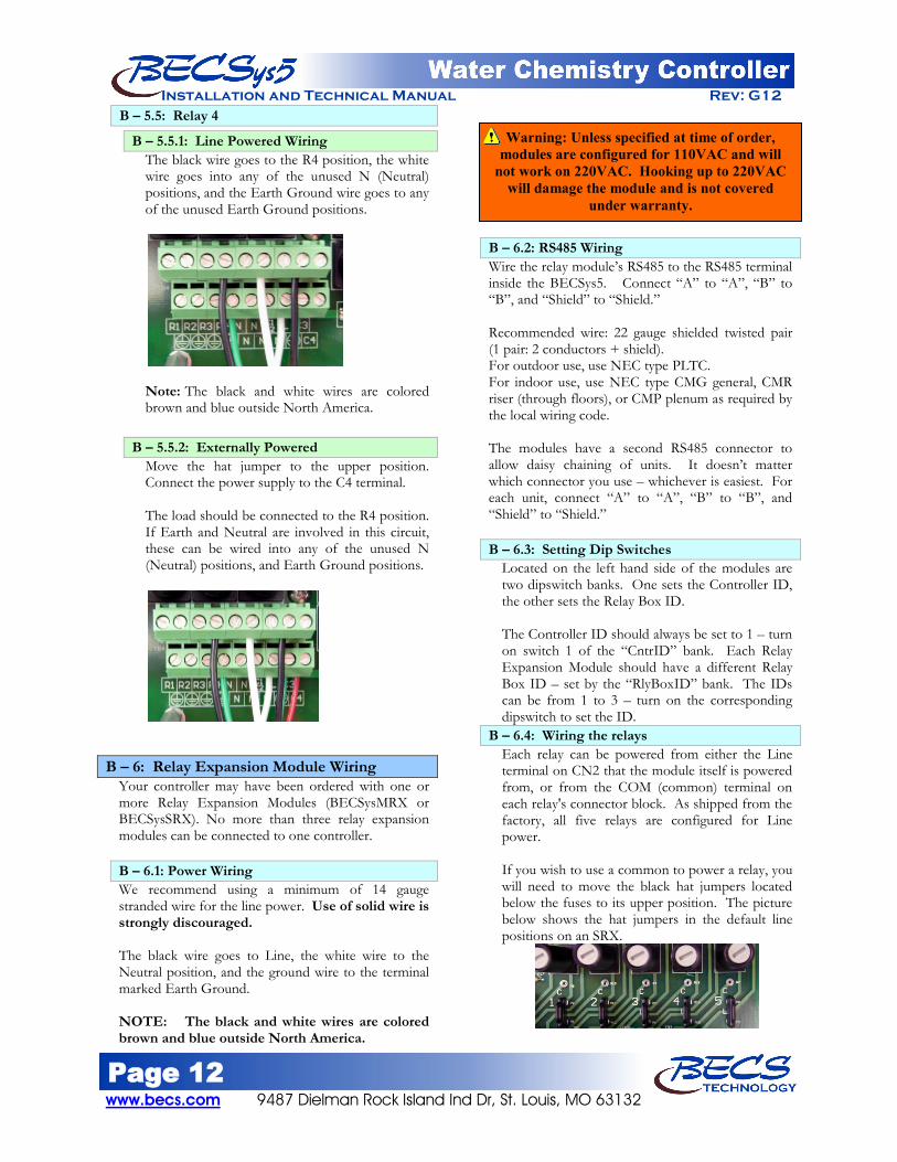
B – 5.5.1: Line Powered Wiring The black wire goes to the R4 position, the white wire goes into any of the unused N (Neutral) positions, and the Earth Ground wire goes to any of the unused Earth Ground positions.
Note: The black and white wires are colored brown and blue outside North America.
B – 5.5.2: Externally Powered
Move the hat jumper to the upper position. Connect the power supply to the C4 terminal. The load should be connected to the R4 position. If Earth and Neutral are involved in this circuit, these can be wired into any of the unused N (Neutral) positions, and Earth Ground positions.
B – 6: Relay Expansion Module Wiring Your controller may have been ordered with one or more Relay Expansion Modules (BECSysMRX or BECSysSRX). No more than three relay expansion modules can be connected to one controller. B – 6.1: Power Wiring We recommend using a minimum of 14 gauge stranded wire for the line power. Use of solid wire is strongly discouraged. The black wire goes to Line, the white wire to the Neutral position, and the ground wire to the terminal marked Earth Ground. NOTE: The black and white wires are colored brown and blue outside North America.
B – 6.2: RS485 Wiring Wire the relay module’s RS485 to the RS485 terminal inside the BECSys5. Connect “A” to “A”, “B” to “B”, and “Shield” to “Shield.” Recommended wire: 22 gauge shielded twisted pair (1 pair: 2 conductors + shield). For outdoor use, use NEC type PLTC. For indoor use, use NEC type CMG general, CMR riser (through floors), or CMP plenum as required by the local wiring code. The modules have a second RS485 connector to allow daisy chaining of units. It doesn’t matter which connector you use – whichever is easiest. For each unit, connect “A” to “A”, “B” to “B”, and “Shield” to “Shield.” B – 6.3: Setting Dip Switches
Located on the left hand side of the modules are two dipswitch banks. One sets the Controller ID, the other sets the Relay Box ID. The Controller ID should always be set to 1 – turn on switch 1 of the “CntrID” bank. Each Relay Expansion Module should have a different Relay Box ID – set by the “RlyBoxID” bank. The IDs can be from 1 to 3 – turn on the corresponding dipswitch to set the ID.
B – 6.4: Wiring the relays Each relay can be powered from either the Line terminal on CN2 that the module itself is powered from, or from the COM (common) terminal on each relay's connector block. As shipped from the factory, all five relays are configured for Line power. If you wish to use a common to power a relay, you will need to move the black hat jumpers located below the fuses to its upper position. The picture below shows the hat jumpers in the default line positions on an SRX.
Warning: Unless specified at time of order, modules are configured for 110VAC and will
not work on 220VAC. Hooking up to 220VAC will damage the module and is not covered
under warranty.

Page 13 9487 Dielman Rock Island Ind Dr, St. Louis, MO 63132 www.becs.com
Installation and Technical Manual Rev: G12
B – 7: Flow Switch Wiring A flow switch must be used in the operation of a BECSys5 Controller A paddlewheel flow switch or reed flow switch must be incorporated into the flow cell to disable chemical feed in the event of loss of flow to the flow cell.
B – 7.1: Paddlewheel Flow Switch
Connect the black wire of the paddlewheel/rotary flow switch to the terminal marked ground, the white wire to the terminal labeled IN, and the red wire to the terminal labeled + 12. The green “flow” light on the flow switch will light whenever flow is present.
B – 7.2: Reed Flow Switch
The reed flow switch is a (2) two-wire switch. Connect the black wire to the terminal labeled IN, and the red wire to the terminal labeled + 12. NOTE: Unlike the paddlewheel flow switch, the reed flow switch is a directional switch. Make sure it is installed with the flow arrow in the proper direction. No check valve is required with the reed flow switch.
B – 8: Amperometric Probe Wiring
Connect the red "A" wire to the A terminal, the "K" white tip with transparent wire to the K terminal, and the thick unlabeled wire to the ground terminal. NOTE: This probe requires a minimum flow velocity of 15 cm/s against its membrane. If the default calibration is off more than 0.3 ppm, the flow rate may be too low. Contact the factory for assistance.
B – 9: Temperature Sensor Wiring
Connect the temperature probe to the Temp terminals. The temperature probe is non-polarized, wire orientation does not matter.
Warning: A check valve is must be installed with the paddlewheel flow switch to prevent backflow when the system is shut down. If a
check valve is not installed, backflow could give the controller a false reading of flow and continue to pump chemicals into the pool.
Warning: NEVER BYPASS FLOW SWITCH CONNECTIONS
The Flow Switch is a critical safety device which prevents uncontrolled chemical feed.
Uncontrolled feeding of chemicals can result in injury or death.
Warning: Failure to incorporate a Flow Switch and Flow cell into the sample
stream of your BECSys chemical controller can result in injury or death to swimmers in or
around the pool if the recirculation pump should fail or shut down.

Page 14 www.becs.com 9487 Dielman Rock Island Ind Dr, St. Louis, MO 63132
Installation and Technical Manual Rev: G12
B – 10: Flow Meter Wiring B – 10.1: +GF+Signet 2536 (Blue Cap)
Connect the black wire to the +12 terminal, the red wire to the IN terminal, and the silver wire to the ground terminal. Set SW1 switches 6 = off, 7 = on. B – 10.2: +GF+Signet 515 (Red Cap)
Connect the red wire to the IN terminal and both the black wire and the silver wire to the ground terminal. Set SW1 switches 6 = on, 7 = off. B – 10.3: +GF+Signet 2551 Magmeter
The magmeter must be configured for frequency output and the pipe size jumper must be set as described in the magmeter's operation manual. A 10K resister installed across pins 1 & 2 is not needed.
Connect pin 1 to the +12 terminal, pin 2 to the IN terminal, and pin 3 to the ground terminal. Set SW1 switches 6 = off, 7 = on (same as blue cap).
B – 11: Conductivity Wiring You may order the BECSys5 with an optional Conductivity Input Board.
Connect the conductivity probe to the Cond terminals. The Conductivity probe is non-polarized (wire orientation does not matter).
Page 15 9487 Dielman Rock Island Ind Dr, St. Louis, MO 63132 www.becs.com
Installation and Technical Manual Rev: G12
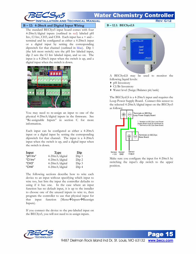
B – 12: 4-20mA and Digital Input Wiring The standard BECSys5 input board comes with four 4-20mA/digital inputs (outlined in red) labeled pH Inv, Cl Inv, CH3, and CH4. Each input has a + and – terminal and be configured as either a 4-20mA input or a digital input by setting the corresponding dipswitch for that channel (outlined in blue). Dip 1 (the left most switch) sets the pH Inv labeled input, dip 2 sets the Cl Inv labeled input, and so on. The input is a 4-20mA input when the switch is up, and a digital input when the switch is down.
You may need to re-assign an input to one of the physical 4-20mA/digital inputs in the firmware. See “Re-assignable Inputs” in section C for more information. Each input can be configured as either a 4-20mA input or a digital input by setting the corresponding dipswitch for that channel. The input is a 4-20mA input when the switch is up, and a digital input when the switch is down. Input Type “pH Inv” 4-20mA/digital Dip 1
Dip
“Cl Inv” 4-20mA/digital Dip 2 “CH3” 4-20mA/digital Dip 3 “CH4” 4-20mA/digital Dip 4 The following sections describe how to wire each device to an input without specifying which input to wire too, but lists the input the controller defaults to using if it has one. In the case where an input function has no default input, it is up to the installer to choose one of the unused inputs to wire to, then program the controller to use that physical input for that input function (MenuInputsReassign Inputs). If you connect the device to the pre-labeled input on the BECSys5, you will not need to re-assign inputs.
B – 12.1: BECSysLS
A BECSysLS may be used to monitor the following liquid levels: pH Inventory Cl/Br Inventory Water level (Surge/Balance pit/tank)
The BECSysLS is a 4-20mA input and requires the Loop Power Supply Board. Connect this sensor to the selected 4-20mA/digital input on the BECSys5 as follows:
Make sure you configure the input for 4-20mA by switching the input’s dip switch to the upper position.

Page 16 www.becs.com 9487 Dielman Rock Island Ind Dr, St. Louis, MO 63132
Installation and Technical Manual Rev: G12 B – 12.2: Floats
Floats may be used to trigger the following: ♦ Low pH Inventory Alarm ♦ Low Cl/Br Inventory Alarm ♦ Low Surge pit Alarm Connect the float to one of the 4-20mA/digital or digital only input on the controller. The float is non polarized (wire orientation does not matter).
Simply connect one wire to the input’s “+” terminal and the other wire to the input’s “–” terminal. Make sure you configure the input as a digital input by switching the input’s dip switch to the down position.
B – 12.3: Turbidity sensor The Turbidity sensor is a 4-20mA self powered device and does not require the use of the loop power supply board. Connect this to an available 4-20mA input as follows: Connect the turbidity sensor’s positive wire to the input’s “+” terminal, and the turbidity sensor’s negative wire to the input’s “–” terminal.
Make sure you configure the input for 4-20mA by switching the input’s dip switch to the upper position.
B – 12.4: Pressure Transducer The pressure transducer is a 4-20mA device that requires the loop power supply board. Pressure transducers can be used to monitor: ♦ Filter Influent Pressure ♦ Filter Effluent Pressure ♦ Pump Effluent Pressure
Wire the transducer to an available 4-20mA/digital input on the controller as follows: ♦ The transducer’s black wire does not get
connected and should be cut off ♦ Use the wire you cut off or another wire to
jumper the loop power supply board’s negative terminal to the negative terminal on the controller’s 4-20mA input.
♦ Connect the red wire to the positive position on the loop power supply board.
♦ Connect the white wire to the positive terminal on the controller’s 4-20mA input.
♦ Make sure you configure input to 4-20mA by switching the input’s dip switch to the upper position.

Page 17 9487 Dielman Rock Island Ind Dr, St. Louis, MO 63132 www.becs.com
Installation and Technical Manual Rev: G12 B – 12.5: Vacuum Transducer
The vacuum transducer is a 4-20mA device that requires the loop power supply board. Vacuum transducers can be used to monitor: ♦ Filter Influent Pressure ♦ Strainer/Drain Vacuum
Wire the transducer to an available 4-20mA/digital input on the controller as follows: ♦ The transducer’s white wire does not get
connected and should be cut off. ♦ Use the wire you cut off or another wire to
jumper the loop power supply board’s negative terminal to the input’s negative terminal.
♦ The red wire should go to the positive connection on the loop power supply board.
♦ The Black wire should go to the “+” terminal on the input.
♦ Make sure you configure input to 4-20mA by switching the input’s dip switch to the upper position.
B – 12.6: Murphy Swichgages
B – 12.6.1: A20P Pressure Gauge A pressure gauge can be used to trigger the following: ♦ High filter influent pressure alarm.
Simply connect the gauge’s “C” terminal and the “N.C.” terminal to the “+” and “–” terminals on an available 4-20mA/digital or digital only input. All Swichgages are non-polarized (wire orientation does not matter). Make sure you configure the input as a digital input by switching the input’s dip switch to the down position.
B – 12.6.2: A20DP Differential Pressure Gauge A differential pressure gauge can be used to trigger the following: ♦ High differential pressure alarm
Connect the gauge’s “C” terminal and the “N.O.” terminal to the “+” and “–” terminals on an available 4-20mA/digital or digital only input. All Swichgages are non-polarized, wire orientation does not matter. Make sure you configure the input as a digital input by switching the input’s dip switch to the down position.
B – 12.6.3: A20V Vacuum Gauge
A vacuum gauge can be used to trigger the following: ♦ High strainer vacuum alarm
Connect the gauge’s “C” terminal and the “N.O.” terminal to the “+” and “–” terminals on an available 4-20mA/digital or digital only input. All Swichgages are non-polarized, wire orientation does not matter. Make sure you configure the input as a digital input by switching the input’s dip switch to the down position.

Page 18 www.becs.com 9487 Dielman Rock Island Ind Dr, St. Louis, MO 63132
Installation and Technical Manual Rev: G12 B – 12.7: Solid State Autofill Sensor
The solid state sensor comes with one of three types of mounting features: .
Wall Mount
Solid State Auto-fill Sensor
shown with wall-mount conduit clamps. Clamps can
be used to secure pipe during installation to side
wall of pit
Stand Pipe Mount
Solid State Auto-fill Sensor shown with 2” stand pipe
mounting feature (isometric & x-sectional
views)
Site Glass Mount
Solid State Auto-fill Sensor shown with site glass mounting
feature (isometric & side views)
The solid state sensor requires the loop power supply board and be used to trigger the following: ♦ Autofill Feed Start/End (single point control) ♦ Autofill Feed Start (dual sensors) ♦ Autofill Feed End (dual sensor) ♦ Low Surge pit Alarm
Input function Low Surge Pit Alarm “Surge”
Default Input
Autofill none
Connect the solid state sensor to one of the available 4-20mA/digital inputs on the controller as follows: ♦ Connect the red wire to the positive terminal
on the loop power supply board. ♦ Connect the white wire to the positive
terminal on the controller’s 4-20mA input. ♦ Connect the black wire to the negative
terminal on the controller’s 4-20mA input. ♦ Jumper the negative terminal on the
controller’s 4-20mA input to the negative terminal on the loop power supply board.
♦ Make sure you configure input to digital input by switching the input’s dip switch to the lower position.

Page 19 9487 Dielman Rock Island Ind Dr, St. Louis, MO 63132 www.becs.com
Installation and Technical Manual Rev: G12 B – 12.8: Total Chlorine Sensor
The Total Chlorine Sensor requires the loop power supply board or 4-20mA output board and the included interface box.
To connect the Total Chlorine Sensor to the interface box: ♦ Connect the Yellow Wire to CN3 “GND
Yellow” ♦ Connect the Brown Wire to CN3 “+12V
Brown” ♦ Connect the Green Wire to CN4 “IN Green” ♦ Connect the White Wire to CN4 “-12V White”
Interface box
To connect the interface box to the BECSys Controller, use the supplied cable. This supplied cable has one end preinstalled to connectors CN1 and CN2 in the interface box. Connect the opposite end to one of the 4-20mA inputs on the BECSys Controller as follows: (Note: Cable may be shortened if needed). ♦ On the Loop Power Supply, install a green
jumper between CH2 – and CH3+ (see next wiring diagram).
♦ Run a wire from CH2+ on the Loop Power Supply Board to the “+” terminal on the input.
♦ From Cable – Connect the Red Wire to CH2+ on the Loop Power Supply.
♦ From Cable – Connect the White Wire to the “–“ terminal on the input.
♦ From Cable – Connect the Black Wire to CH3 – on the Loop Power Supply.
♦ From Cable – Connect the Green Wire to CH3+ on the Loop Power Supply.
♦ Make sure you configure input to 4-20mA by switching the input’s dip switch to the upper position.
Controller Wiring
B – 13: 4-20mA Output Wiring Your controller may have been ordered with one or two 4-20mA output boards. Using this you can connect the controller to a building management system or other device. You would connect the “+” on the 4-20mA output board
to the “+” on the device and the “-“ on the 4-20mA output board to the “-“ on the device.

Page 20 www.becs.com 9487 Dielman Rock Island Ind Dr, St. Louis, MO 63132
Installation and Technical Manual Rev: G12
B – 14: BECSysRPM (Remote Probe Module) Your controller may have been ordered with a BECSys Remote Probe Module Interface Board. Using this, you may connect to a BECSys Remote Probe Module (BECSysRPM). The BECSysRPM provides a method of extending the probe signal. B – 14.1: Wiring the BECSysRPM:
Remove the cover of the BECSysRPM by loosening the four screws at the corners with a screwdriver. Note: The screws are captive and do not need to be totally removed, but only loosened. Once the cover has been removed, you will see two sets of connectors. The left bank of connectors provides connection between the BECSysRPM and the BECSys5. The right bank of connectors provides connection for the Flow Switch and Temperature Sensor.
Wiring the Temperature Sensor: Connect the Temperature Sensor to the RTD-IN + and RTD-IN – connectors on the right bank. The Temperature Sensor is non-polarized, wire orientation does not matter.
Wiring a Paddlewheel Flow Switch: Connect the black wire of the paddlewheel/rotary flow switch to the terminal labeled GND, the white wire to the terminal labeled Flow, and the red wire to the terminal labeled +12V. The green “flow” light on the flow switch will light whenever flow is present.
Wiring a Reed Flow Switch: The reed flow switch is a two wire switch. Connect the black wire to the terminal labeled “FLOW” and the red wire to the terminal labeled “+12V”.
NOTE: Unlike the paddlewheel flow switch, the reed flow switch is a directional switch. Make sure it is installed with the flow arrow in the proper direction. No check valve is required with the reed flow switch.
Connecting the Probes: Remove the protective covers from the BNCs. Plug the pH sensor into the coded BNC jack and the ORP sensor into the coded BNC jack on the bottom of the BECSysRPM by twisting them a quarter of a turn.
B – 14.2: Wiring to the BECSys5: There are a total of seven connections that must be made between the BECSys5 and the BECSysRPM (24 gauge wire is acceptable to use).
Power: Power is provided to the BECSysRPM from the BECSys Remote Probe Module Interface Board. Connect the terminal labeled +12V on the BECSysRPM Interface Board to the terminal marked +12V on the BECSysRPM (left bank of connectors). Connect the terminal labeled GND on the BECSysRPM Interface Board to the terminal marked GND on the BECSysRPM (left bank of connectors).
Probe Signal: From the BECSysRPM Interface Board connect the terminal labeled Out(1) to Out(1) on the BECSysRPM. Connect Out(2) to Out(2) on the BECSysRPM.
Flow: On the BECSys5 CPU board, connect a wire to “IN” on the Flow Switch Input. Connect the other end to the terminal labeled “FLOW” on the BECSysRPM. The +12V and GND on the BECSys5 Flow Switch Input are not used.
Temperature: From the BECSys5 Input Board, connect two wires to the “Temp” input. Connect the other end of these two wires to the terminal labeled “RTD-OUT +” and “RTD-OUT –“. The temperature input is not polarized, wire orientation does not matter.
Warning: A check valve is must be installed with the paddlewheel flow switch to prevent backflow when the system is shut down. If a check valve is not installed, backflow could give the controller a false reading of flow and continue to pump chemicals into the pool.

Page 21 9487 Dielman Rock Island Ind Dr, St. Louis, MO 63132 www.becs.com
Installation and Technical Manual Rev: G12
B – 15: BECSys Ethernet Board Use these wiring instructions for controllers that come with a BECSys Ethernet board installed at the factory. If you are installing a BECSys Ethernet board into a controller yourself, use the instructions supplied with the BECSys Ethernet board instead of these. Connected to the end of the network cable is an in-line coupler. You may either connect a cable directly to this or remove the coupler and connect to a wall jack.
B – 16: Re-installing the safety shield
Gently place the safety shield over the fuse holders – you may have to adjust the fuse holders a little in order for it to fit properly. Once the shield is sitting flat, replace the four screws.
B – 17: Fuses 115VAC Model (F4):
¼ Amp 250V Time Lag Fuse (¼” x 1¼”) 230VAC Model (F4):
⅛ Amp 250V Time Lag Fuse (¼” x 1¼”) Relay Fuses (F1 – F4):
3 Amp 250V Time Lag Fuse (¼” x 1¼”) RS485 Fuse (F11 CPU Board):
¼ Amp 250V Time Lag Microfuse (5.08mm)
Warning: The controller must be connected to a Standard Ethernet Port. Connecting to a Power Over Ethernet (POE) Port will cause damaged to
the controller.

Page 22 www.becs.com 9487 Dielman Rock Island Ind Dr, St. Louis, MO 63132
Installation and Technical Manual Rev: G12
Section C: Programming the Controller
C – 1: Adjusting the Display Contrast You can adjust the display contrast by holding down either the up or down arrow keys for two seconds, then after the controller beeps three times, use the up and down keys to adjust the contrast.
C – 2: Security Settings C – 2.1: Access Codes and levels
The BECSys5 controller ships from the factory with all access codes disabled. The controller will not ask you for an access code when you press the menu or other quick buttons until you enable and set the Rep access code and at least one Operator access code. Setting Manager access codes is optional. If the Rep access code is disabled, you are automatically given rep access without the controller prompting you for an access code. This is true even if you set an Operator and/or Manager access codes. To view who is currently logged on, press the lock screen button while in any menu.
The Main Menu will also display who is logged on along with the version of firmware. You do not need to set all the access codes for each level if you do not wish to. Also, a disabled access code is not equivalent to 000, so entering 000 when it prompts for an access code will only work if you have specifically assigned an access code to be 000.
NOTE: Once access codes have been set, certain programmable options will not be accessible to Operators and Managers.
Until you set the rep access code, you will always have rep access, and until you set at least one operator code, the controller will never prompt you to enter an access code to gain access to a particular screen (see table).
Rep Managers Operators Access level given
Not set Don't care Don't care Rep Set Not set Not set Manager Set 1 or both set Not set Operator Set Don't care 1 or more set Prompt
Setting just the rep access code will result in the default access level being Manager, and the controller will still not prompt you
C – 2.2: Setting Access Codes
to enter in an access code when you press the Menu or other face panel buttons. However, any items exclusive to rep access will not be shown unless you log on manually via the Logon selection in the main menu.
To set an access code, press the menu button, then:
Select System Config Choose User Setup Then select the access level you want to set an
access code for. To set Operator 1's access code, you would select Oper. Access Codes, then select Operator 1.
Pressing and holding the +/- button disables the access code, while pressing enter will enable and set the access code to the value on the screen. Operators may only change their own access code. Managers may change their access code and any of the Operators. Reps can change anyone's access code.
Warning: It is strongly recommended to set a Rep Access Code. By not setting a Rep Access
Code, anyone can access Rep Menus.

Page 23 9487 Dielman Rock Island Ind Dr, St. Louis, MO 63132 www.becs.com
Installation and Technical Manual Rev: G12 C – 2.3: Recovering Lost Access Codes
If an access code is forgotten, the code can be recovered by the following procedure:
1. Flip switch 2 on SW1 to the on position.
2. Press Menu, and if necessary select logon to
bring up the Access Menu.
3. Select the level of the access code you wish
to recover. 4. Record the encrypted value(s) displayed
beneath the prompt and turn Dip 2 off when done. The example below shows the encrypted codes for Op1 (D), Op3 (F), and Op4 (G), while Op2, Op5, & Op6 are disabled on that system.
5. BECS Technology can be contacted for
decryption of this code, providing the original access code.
C – 2.4: Setting Permissions You may set what operators, managers, or anyone have access to in the Permissions menu. By default, all permissions are set to their lowest level (Oper, Mgr, & Rep or Anyone). When you select the Permissions menu under the User Setup menu, you are given several options to choose from. By selecting one of these options you are able to select who has access to what. If “Oper, Mgr & Rep” is selected, everyone with an access code is able to modify that setting. If “Mgr & Rep” is selected, only Managers and Reps are able to modify the settings. If “Rep only” is selected, only Reps are able to modify the setting.
If you set the permissions for Calibrations, when you press the Cal button while in the normal display, the unit will display the current enabled inputs. Once you select input to calibrate, you will then be prompted to log into the controller. If you do not have permission to change the value, “Access level denied” will be displayed in the status area. A third permission level is set up for Emergency Off and Reset Fail/Safe. This level is “Anyone” and is the default setting. If the permission setting is “Anyone”, you may access these functions without logging onto the controller.
C – 3: Navigating the menus The controller's menus incorporate built in help text to aid in understanding the function of each parameter, item, and option. C – 3.1: Common status messages
The very bottom line of the display contains the time and date on the left while the right is reserved for a number of status messages; the most common are as follows:
"Busy..." - Indicates the controller is busy doing something critical and it cannot stop until it finishes. Until this message disappears, the controller will not respond to your key presses (although it does record them any will process them when done). Normally this message is only seen briefly after changing a setting, but it is also used for lengthier operations such as factory defaults and in the extremely rare case where the internal diagnostics detect a memory problem and attempts to correct it.
"(1 of 2) (More )" - and the like indicate there are more options for you to choose from than the controller could show at one time. Press the right arrow key (Next) to view them. The left number indicates the current page, while the right number indicates the total number of pages.
"Bad Value, Retry..." - Accompanied by an error beep, this indicates the value you just entered was not within the allowable range of values and was not stored.
Warning: Interrupting the controller by turning the power off while it displays the busy message could result in the complete loss of all
of its settings.
Page 24 www.becs.com 9487 Dielman Rock Island Ind Dr, St. Louis, MO 63132
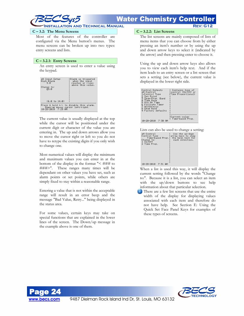
Installation and Technical Manual Rev: G12 C – 3.2: The Menu Screens
Most of the features of the controller are configured via the Menu button's menus. The menu screens can be broken up into two types: entry screens and lists.
C – 3.2.1: Entry Screens An entry screen is used to enter a value using the keypad.
The current value is usually displayed at the top while the cursor will be positioned under the current digit or character of the value you are entering in. The up and down arrows allow you to move the cursor right or left so you do not have to retype the existing digits if you only wish to change one. Most numerical values will display the minimum and maximum values you can enter in at the bottom of the display in the format "< ### to ###>". These ranges many times will be dependant on other values you have set, such as alarm points or set points, while others are simply fixed to stay within a reasonable range. Entering a value that is not within the acceptable range will result in an error beep and the message "Bad Value, Retry..." being displayed in the status area. For some values, certain keys may take on special functions that are explained in the lower lines of the screen. The Down/up message in the example above is one of them.
C – 3.2.2: List Screens The list screens are mainly composed of lists of menu items that you can choose from by either pressing an item's number or by using the up and down arrow keys to select it (indicated by the arrow) and then pressing enter to choose it. Using the up and down arrow keys also allows you to view each item's help text. And if the item leads to an entry screen or a list screen that sets a setting (see below), the current value is displayed in the lower right side.
Lists can also be used to change a setting:
When a list is used this way, it will display the current setting followed by the words "Change to:". Because it is a list, you can select an item with the up/down buttons to see help information about that particular selection.
There are a few list screens that use the entire width of the display for displaying values associated with each item and therefore do not have help. See Section E: Using the Quick Set Face Panel Keys for examples of these types of screens.

Page 25 9487 Dielman Rock Island Ind Dr, St. Louis, MO 63132 www.becs.com
Installation and Technical Manual Rev: G12 C – 3.3: The Lock Screen Key
When not in a menu (i.e. viewing the normal display), pressing the lock screen key will prevent the controller from paging the screen to show more inputs, alarms, and other status information. See Section D: The Normal Display for more info about using the lock screen key in the normal display. While within any menu, if the user does not press a key within sixty seconds of the last key press, the current user is logged out and the screen is returned to the normal display. To prevent the controller from timing out, you may lock the screen. While within a menu, pressing the Lock Screen key will bring up a popup menu:
The first option on the popup will be either to lock or unlock the screen depending on the current lock state. While the screen is locked, key presses normally are ignored. However, in some instances certain keys are given special functions while the screen is locked, such as using the up and down arrows to scroll the help text if all of the help text cannot be displayed at once.
You can also lock/unlock the screen without bringing up the popup menu by holding down the lock button for one second. The controller will acknowledge this action with a triple beep and the yellow Lock Screen light will turn on.
The Lock button popup menu also identifies who is currently logged on, and provides an option for the user to log off. You can also select cancel if you pressed the lock button in error.
Page 26 www.becs.com 9487 Dielman Rock Island Ind Dr, St. Louis, MO 63132
Installation and Technical Manual Rev: G12
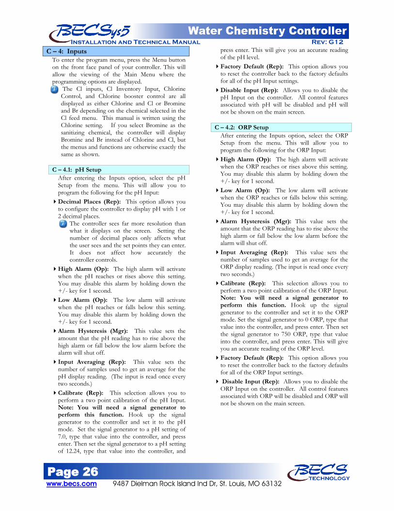
C – 4: Inputs To enter the program menu, press the Menu button on the front face panel of your controller. This will allow the viewing of the Main Menu where the programming options are displayed.
The Cl inputs, Cl Inventory Input, Chlorine Control, and Chlorine booster control are all displayed as either Chlorine and Cl or Bromine and Br depending on the chemical selected in the Cl feed menu. This manual is written using the Chlorine setting. If you select Bromine as the sanitizing chemical, the controller will display Bromine and Br instead of Chlorine and Cl, but the menus and functions are otherwise exactly the same as shown.
C – 4.1: pH Setup
After entering the Inputs option, select the pH Setup from the menu. This will allow you to program the following for the pH Input:
Decimal Places (Rep): This option allows you to configure the controller to display pH with 1 or 2 decimal places.
The controller sees far more resolution than what it displays on the screen. Setting the number of decimal places only affects what the user sees and the set points they can enter. It does not affect how accurately the controller controls.
High Alarm (Op): The high alarm will activate when the pH reaches or rises above this setting. You may disable this alarm by holding down the +/- key for 1 second.
Low Alarm (Op): The low alarm will activate when the pH reaches or falls below this setting. You may disable this alarm by holding down the +/- key for 1 second.
Alarm Hysteresis (Mgr): This value sets the amount that the pH reading has to rise above the high alarm or fall below the low alarm before the alarm will shut off.
Input Averaging (Rep): This value sets the number of samples used to get an average for the pH display reading. (The input is read once every two seconds.)
Calibrate (Rep): This selection allows you to perform a two point calibration of the pH Input. Note: You will need a signal generator to perform this function. Hook up the signal generator to the controller and set it to the pH mode. Set the signal generator to a pH setting of 7.0, type that value into the controller, and press enter. Then set the signal generator to a pH setting of 12.24, type that value into the controller, and
press enter. This will give you an accurate reading of the pH level.
Factory Default (Rep): This option allows you to reset the controller back to the factory defaults for all of the pH Input settings.
Disable Input (Rep): Allows you to disable the pH Input on the controller. All control features associated with pH will be disabled and pH will not be shown on the main screen.
C – 4.2: ORP Setup After entering the Inputs option, select the ORP Setup from the menu. This will allow you to program the following for the ORP Input:
High Alarm (Op): The high alarm will activate when the ORP reaches or rises above this setting. You may disable this alarm by holding down the +/- key for 1 second.
Low Alarm (Op): The low alarm will activate when the ORP reaches or falls below this setting. You may disable this alarm by holding down the +/- key for 1 second.
Alarm Hysteresis (Mgr): This value sets the amount that the ORP reading has to rise above the high alarm or fall below the low alarm before the alarm will shut off.
Input Averaging (Rep): This value sets the number of samples used to get an average for the ORP display reading. (The input is read once every two seconds.)
Calibrate (Rep): This selection allows you to perform a two point calibration of the ORP Input. Note: You will need a signal generator to perform this function. Hook up the signal generator to the controller and set it to the ORP mode. Set the signal generator to 0 ORP, type that value into the controller, and press enter. Then set the signal generator to 750 ORP, type that value into the controller, and press enter. This will give you an accurate reading of the ORP level.
Factory Default (Rep): This option allows you to reset the controller back to the factory defaults for all of the ORP Input settings.
Disable Input (Rep): Allows you to disable the ORP Input on the controller. All control features associated with ORP will be disabled and ORP will not be shown on the main screen.

Page 27 9487 Dielman Rock Island Ind Dr, St. Louis, MO 63132 www.becs.com
Installation and Technical Manual Rev: G12 C – 4.3: Cl Inputs Setup
C – 4.3.1: Free Cl Setup After entering the Input option, select the Cl Inputs Setup from the menu, then select Free Cl Setup. This will allow you to program the following for the free chlorine sensor input:
Input Source (Rep): Once you have entered the free Cl setup menu, select Input Source. Here you can select whether your free Cl reading will be by calculation, amperometric probe, or disabled. C – 4.3.1.1: Input Source: Calculated High Alarm (Op): The high alarm will
activate when the free Cl reaches or rises above this setting. You may disable this alarm by holding down the +/- key for 1 second.
Low Alarm (Op): The low alarm will activate when the free Cl reaches or falls below this setting. You may disable this alarm by holding down the +/- key for 1 second.
Alarm Hysteresis (Mgr): This value sets the amount that the Cl input readings have to rise above their high alarm or fall below their low alarm before the alarm will shut off.
Factory Default (Rep): This option allows you to reset the controller back to the factory defaults for all the free Cl Input settings.
C – 4.3.1.2: Input Source: Probe Decimal Places (Rep): This option allows
you to configure the controller to display all Cl inputs with 1 or 2 decimal places.
High Alarm (Op): The high alarm will activate when the free Cl reaches or rises above this setting. You may disable this alarm by holding down the +/- key for 1 second.
Low Alarm (Op): The low alarm will activate when the free Cl reaches or falls below this setting. You may disable this alarm by holding down the +/- key for 1 second.
Alarm Hysteresis (Mgr): This value sets the amount that the Cl input readings have to rise above their high alarm or fall below their low alarm before the alarm will shut off. Note this value is used for free, total, and combined Cl alarms.
Input Averaging (Rep): This value sets the number of samples used to get an average for the free Cl display reading. (The input is read once every two seconds.)
Zero point Cal (Rep): This menu informs the installer how to calibrate the input at 0 ppm. This is optional for CCS140 sensors but ECL6 sensors require this calibration when sensor is first installed. To calibrate, shut off flow, fill flow cell with distilled water, let sit for 30 minutes, then enter 0 for the value in this or any single point calibration screen.
Calibrate (Op): This selection allows you to do a single point calibration of free Cl, enter the reading from you test kit, and press enter. The value entered must be 0.5 ppm or greater.
Reset Calibration (Op): Resets the calibration to the original factory setting.
Interlock Duration (Rep): Shown only if the sensor is CCS140. Enter the amount of time to wait after providing power to the probe before allowing free Cl-based control and press enter. (the range is 0:30 to 18:00 hours) When power is first applied to the CCS140 sensor, it takes time for the probe to polarize and give accurate readings. Depending on the probe and the situation, this time can be as little as ten minutes and as long as a half an hour. While the interlock timer is active, all free Cl-based controls are disabled, defaulting to ORP control if available.
Factory Default (Rep): This option allows you to reset the controller back to the factory defaults for all the free Cl Input settings.

Page 28 www.becs.com 9487 Dielman Rock Island Ind Dr, St. Louis, MO 63132
Installation and Technical Manual Rev: G12 C – 4.3: Cl Inputs Setup (continued)
C – 4.3.2: Total Cl Setup The Total Cl input is a 4-20mA input that is not assigned to a physical input by default. Before you can even see the Total Cl Setup menu, you must first reassign one of the 4-20mA inputs to the Total Cl function.
Enable input (Rep): Enables or disables the Total Cl input.
High Alarm (Op): The high alarm will activate when the total Cl reaches or rises above this setting. You may disable this alarm by holding down the +/- key for 1 second.
Low Alarm (Op): The low alarm will activate when the total Cl reaches or falls below this setting. You may disable this alarm by holding down the +/- key for 1 second.
Alarm Hysteresis (Mgr): This value sets the amount that the Cl input readings have to rise above their high alarm or fall below their low alarm before the alarm will shut off. Note this value is used for free, total, and combined Cl alarms.
Input Averaging (Rep): This value sets the number of samples used to get an average for the total Cl display reading. (The input is read once every two seconds.)
Zero point Cal (Rep): A calibration < 1.5 ppm and second calibration at > 2.5 ppm are required at installation. This menu informs the installer how to calibrate the input at 0 ppm. To calibrate, shut off flow, fill flow cell with distilled water, let sit for 15 minutes, then enter 0 for the value in this or any other single point calibration screen. This calibration can also be done without shutting off flow with water < 1.5 ppm by performing a standard water test kit calibration. You MUST have flow if you’re not using distilled water.
2nd point Cal (Rep): A calibration < 1.5 ppm and second calibration at > 2.5 ppm are required at installation. This menu informs the installer how to complete the initial calibration when using distilled water. Restore flow, wait 15 minutes, then perform test kit singe point calibration entering a value > 2.5 ppm.
C – 4.3.3: Combined Cl The combined Cl option is only shown if both the free and total Cl probes are installed and enabled. The value is calculated from the total and free Cl readings.
High Alarm (Op): The high alarm will activate when the combined Cl reaches or rises above this setting. You may disable this alarm by holding down the +/- key for 1 second.
Alarm Hysteresis (Mgr): This value sets the amount that the Cl input readings have to rise above their high alarm or fall below their low alarm before the alarm will shut off. Note this value is used for free, total, and combined Cl alarms.
C – 4.4: Temperature Setup After entering the Input option, choose the Temperature Setup from the menu. This will allow you to program the following for the Temperature Input:
Temp Input Enable (Rep): If a Temperature Sensor is installed, enable this input.
The included temperature probe must be installed in the flow cell and connected to the controller for the temperature display to work.
If enabled, you will have the following options:
High Alarm (Op): The high alarm will activate when the temperature reaches or rises above this setting. You may disable this alarm by holding down the +/- key for 1 second.
Low Alarm (Op): The low alarm will activate when the temperature reaches or falls below this setting. You may disable this alarm by holding down the +/- key for 1 second.
Input Averaging (Rep): This value sets the number of samples used to get an average for the temperature display reading. (The input is read once every two seconds.)
Alarm Hysteresis (Mgr): This value sets the amount that the temperature reading has to rise above the high alarm or fall below the low alarm before the alarm will shut off.
Calibrate (Rep): This selection allows you to perform a two point calibration of the Temperature Input. Note: You will need a signal generator to perform this function. Hook up the signal generator to the controller and set it to the temperature mode (RTD). Set the signal generator to 59 degrees, type that value into the controller, and press enter. Then set the signal generator to 123 degrees, type that value into the controller, and press enter. This will give you an accurate reading of the temperature.
Factory Default (Rep): This option allows you to reset the controller back to the factory defaults for all the Temperature Input settings.

Page 29 9487 Dielman Rock Island Ind Dr, St. Louis, MO 63132 www.becs.com
Installation and Technical Manual Rev: G12 C – 4.5: Conductivity/TDS Setup
Note: Available only with Conductivity Input Board.
After entering the Input option, choose the Conductivity Setup from the menu. This will allow you to program the following for the Conductivity Input:
Input Enable (Rep): If a Conductivity/TDS Sensor is installed, enable this input. If enabled, you will have the following options:
Units (Rep): This allows you to choose the units conductivity will be displayed in. You may choose either conductivity (μmhos) or TDS (ppm).
High Alarm (Op): The high alarm will activate when the input reaches or rises above this setting. You may disable this alarm by holding down the +/- key for 1 second.
Low Alarm (Op): The low alarm will activate when the input reaches or falls below this setting. You may disable this alarm by holding down the +/- key for 1 second.
Input Averaging (Rep): This value sets the number of samples used to get an average for the Conductivity/TDS display reading. (The input is read once every two seconds.)
Alarm Hysteresis (Mgr): This value sets the amount that the Conductivity/TDS reading has to rise above the high alarm or fall below the low alarm before the alarm will shut off.
Calibrate (Rep): This selection allows you to perform a two point calibration of the Conductivity/TDS Input.
Factory Default (Rep): This option allows you to reset the controller back to the factory defaults for all the Conductivity/TDS Input settings.
C – 4.6: Flow Rate Setup After entering the Inputs menu, choose the Flow Rate Setup from the menu. This will allow you to program the following for the Flow Rate Input:
Input Range (Rep): Allows you to change ranges between gpm and kgpm or lpm and klpm.
Max Flow Rate (Rep): Set this value to the pump’s maximum flow rate. This is mainly used to help scale VFD control, but may be used in future for other features.
Display Volume (Rep): Selects whether or not to display the filter volume on the normal display.
K Factor (Rep): (See Section I for values) The K Factor is the number of pulses the sensor will generate for each engineering unit of water that passes by it. The K Factor is determined by the size and material of the pipe as well as the fittings that are used.
No Chemical Feeds on Low Flow Alarm (Rep): Chooses whether or not to lockout chemical feeding on a low flow alarm.
Low Alarm (Op): The low alarm will activate when the flow rate reaches or falls below this setting. You may disable this alarm by holding down the +/- key for 1 second.
Alarm Hysteresis (Mgr): This value sets the reading that the flow rate must rise above the low alarm before the alarm will shut off.
Input Averaging (Rep): This value sets the number of samples used to get an average for the flow rate display reading.
The controller updates the flow rate every two seconds by taking the total number of pulses recorded over the last ten seconds, multiplying that by six (to get sixty seconds or 1 minute), then divides by the K factor to get gpm or lpm. The ten second timeframe is an average by itself, so you should only set the Input Averaging to greater than one if the flow rate reading bounces up and down.
Factory Defaults (Rep): This option allows you to reset the controller back to the factory defaults for all of the Flow Rate Input settings.

Page 30 www.becs.com 9487 Dielman Rock Island Ind Dr, St. Louis, MO 63132
Installation and Technical Manual Rev: G12 C – 4.7: pH & Chlorine Inventory Setups
After entering the Inputs menu, choose pH Inv or Cl Inv from the menu. This will allow you to program the following for the selected inventory input.
Sensor Type (Rep): 4-20 mA
Input: Select this if you are using a BECSysLS or similar 4-20mA device. The controller will prompt you to choose between level or weight, and then ask you for the input range of the sensor. The input range is whatever the maximum value the sensor is rated to measure and ideally the value represented by 20mA.
N.O. dry contact:
Select this if you are using a float with normally open contact switches closing when the chemical level falls below the point you wish an alarm to be triggered.
N.C. dry contact:
Select this if you are using a float with normally closed contact switches opening when the chemical level falls below the point you wish an alarm to be triggered.
Not Installed: No sensor installed.
C – 4.7.1: Sensor Type 4-20mA Input Be sure to set the dipswitch to the 4-20mA position.
Sensor Type (Rep): Allows you to change the sensor type to a different type.
Level or Weight (Rep): Choose if your inventory is to be measured by the level of chemical or the weight of the chemical.
Input Range (Rep): This value sets the input range which is whatever the maximum value the sensor is rated to measure and ideally the value represented by 20mA.
Low Alarm (Op): This value sets at what level or weight the inventory low alarm will be activated. You may disable this alarm by holding down the +/- key for 1 second.
Alarm Hysteresis (Mgr): This value sets at what level the inventory level or weight has to rise above the low level or weight alarm setting before the alarm will shut off.
Input Averaging (Rep): This value sets the number of samples used to get an average for the inventory level.
Calibrate (Rep): Once you have entered Inventory Setup, select Calibrate from the menu.
This calibration is only needed if the readings are accurate at one level/weight, but are off by an increasing amount the farther away you go from that level/weight. If the reading is off by a consistent amount throughout the input range, perform a single point calibration by pressing the Cal button and selecting this input from the list. It is important that the Input Range is set to the correct value; otherwise you may find that the controller refuses to accept the second value due to it being "out of range" or "points too close" (see below).
Calibration is a two step process:
1) While the inventory is low, measure or estimate the current level/weight, enter this value in as the first point and press enter. The controller will not time out and exit the menu while waiting for the second point of a calibration, so you do not need to lock the screen here.
2) Fill the inventory by a known amount. Add this amount to the value you entered for the first point, enter the sum as the second point.
If you get a "points too close" error message, either the values you entered or the input readings taken for those values were too close together to perform an accurate calibration calculation. You either did not add enough inventory, the Input Range is wrong for the sensor attached, or there could be a problem with the wiring if the reading did not change when you added the inventory. If you get a "out of range" error message, you entered a value outside of the configured Input Range. If the sensor is supposed to be able to measure the value you entered, then the Input Range was not set to the correct value and should be corrected. If you discover later that your first point was off, simply do a single point calibration to correct it.
Factory Defaults (Rep): This option allows you to reset the controller back to the factory defaults for all of the inventory input settings.
C – 4.7.2: Sensor Type dry contact (NO or NC) Be sure to set the dipswitch to the digital position.
This setting will give you the following option: Sensor Type (Rep): Allows you to change the
sensor type to a different type.

Page 31 9487 Dielman Rock Island Ind Dr, St. Louis, MO 63132 www.becs.com
Installation and Technical Manual Rev: G12 C – 4.8: Turbidity
The Turbidity input is a 4-20mA input that is not assigned to a physical input by default. Before you can even see the Turbidity setup menu, you must first reassign one of the 4-20mA inputs to the Turbidity function.
After entering the Inputs menu, choose Turbidity from the menu. This will allow you to program the following for the Turbidity Input.
Enable Input (Rep): If a Turbidity Meter is installed, enable this input.
Be sure to set the dipswitch to the 4-20mA position.
If enabled, you will have the following options: High Alarm (Op): The high alarm will activate
when the input reaches or rises above this setting. You may disable this alarm by holding down the +/- key for 1 second.
Alarm Hysteresis (Mgr): This value sets the level that the turbidity reading has to rise above the high alarm setting before the alarm will shut off.
Input Averaging (Rep): This value sets the number of samples used to get an average for the turbidity display reading. (The input is read once every two seconds.)
Calibrate (Rep): Perform a two point calibration of the turbidity input.
Input Range (Rep): Enter the sensor's input range which is whatever the maximum value the sensor is rated to measure and ideally the value represented by 20mA.
Factory Defaults (Rep): This option allows you to reset the controller back to the factory defaults for all of the turbidity input settings.
C – 4.9: Surge Pit Level The Surge Pit Level input is a 4-20mA input that is not assigned to a physical input by default. Before you can even see the Surge Pit Level Setup menu, you must first reassign one of the 4-20mA inputs to the Surge Pit Level function.
Sensor Type (Rep): Once you have entered the Surge Level, select Sensor Type from the menu. Here you will be able to choose between:
4-20 mA Input:
The controller will prompt you for the input range of the sensor. The input range is whatever the maximum value the sensor is rated to measure and ideally the value represented by 20mA.
N.O. dry contact:
Select this if you are using a float with normally open contact switches closing when the surge pit level reaches the point you wish the alarm to be triggered.
N.C. dry contact:
Select this if you are using a float with normally closed contact switches opening when the surge pit level reaches the point you wish the alarm to be triggered.
Not Installed: No sensor installed.
C – 4.9.1: Sensor Type 4-20mA Input Be sure to set the dipswitch to the 4-20mA position.
High Alarm (Op): The high alarm will activate when the input reaches or rises above this setting. You may disable this alarm by holding down the +/- key for 1 second.
Low Alarm (Op): The low alarm will activate when the input reaches or falls below this setting. You may disable this alarm by holding down the +/- key for 1 second.
Alarm Hysteresis (Mgr): This value sets the amount that the surge pit level has to rise above the high alarm or fall below the low alarm before the alarm will shut off.
Input Averaging (Rep): This value sets the number of samples used to get an average for the surge pit level. Enter the desired number and press enter. (The input is read once every two seconds.)
Calibrate (Rep): Performs a two point calibration of the Surge Pit Level Input.
Input Range (Rep): This value sets the input range which should be whatever the maximum value the sensor is rated to measure and ideally the value represented when the sensor outputs 20mA.
Label (Rep): Allows you to rename the Surge Pit input. There is a 12 character maximum.
Factory Defaults (Rep): This option allows you to reset the controller back to the factory defaults for all of the surge pit level input settings.
C – 4.9.2: Sensor Type Dry Contact (NO or NC) Be sure to set the dipswitch to the digital position.
This setting will give you the following options: Sensor Type (Rep): Allows you to change the
sensor type to a different type. Label (Rep): Allows you to rename the Surge
Pit input. There is a 12 character maximum.

Page 32 www.becs.com 9487 Dielman Rock Island Ind Dr, St. Louis, MO 63132
Installation and Technical Manual Rev: G12 C – 4.10: Pressure & Vacuum Setup
The Pressure and Vacuum inputs are 4-20mA inputs that are not assigned to physical inputs by default. Before you can even see the Pressure and Vacuum Setup menu, you must first reassign the 4-20mA inputs to the Pressure and Vacuum functions.
C – 4.10.1: Filter Influent Pressure Once Filter Influent Pressure has been selected, you will need to set the following:
Sensor Type (Rep): PSI
Transducer: Select this if you are using a pressure transducer that will output a 4-20mA signal. The controller will prompt you for the input range of the sensor. The input range is whatever the maximum value the sensor is rated to measure and ideally the value represented by 20mA.
N.O. dry contact:
Select this if you are using a gauge with normally open contact switches closing on a high or low pressure.
N.C. dry contact:
Select this if you are using a gauge with normally closed contact switches opening on a high or low pressure.
Vac Transducer:
Select this if you are using a vacuum transducer that will output a 4-20mA signal. The controller will prompt you for the input range of the sensors. The input range is whatever the maximum value the sensor is rated to measure and ideally the value represented by 20mA.
Not Installed: No sensor installed.
C – 4.10.1.1: PSI & Vacuum Transducer Be sure to set the dipswitch to the 4-20mA position.
Sensor Type (Rep): Allows you to change the sensor type to a different type.
Units (Rep): Shown only if the Sensor type is set to Vacuum Transducer. Selects the units to display this input in. The choices for US units are PSI (+/-) or in-Hg (+/-), and for metric kPa (+/-) or cm-Hg (+/-).
Input Range: (Rep): Enter the transducer’s input range which is whatever the maximum value the sensors are rated to
measure and ideally the value represented by 20mA.
High Alarm (Op): The high alarm will activate when the pressure reaches or rises above this setting. You may disable this alarm by holding down the +/- key for 1 second.
Low Alarm (Op): The low alarm will activate when the pressure falls below this setting. You may disable this alarm by holding down the +/- key for 1 second.
Alarm Hysteresis: (Mgr) This value sets the amount that the pressure reading has to rise above the high alarm or fall below the low alarm before the alarm will shut off.
Input Averaging (Rep): This value sets the number of samples used to get an average for the pressure display reading. (The input is read once every two seconds.)
Display Input (Op): This option enables/disables displaying the influent pressure on the normal display.
Calibrate (Rep): This selection allows you to perform a two point calibration of the Influent Pressure Input.
Factory Defaults (Rep): This option allows you to reset the controller back to the factory defaults for all the Influent Pressure Input settings.
C – 4.10.1.2: Dry Contact (NO or NC)
Be sure to set the dipswitch to the digital position.
This setting will give you the following options: Sensor Type (Rep): Allows you to change
the sensor type to a different type. See above section for a description of the selections under this menu.
Factory Defaults (Rep): This option allows you to reset the controller back to the factory defaults for all the Influent Pressure Input settings.
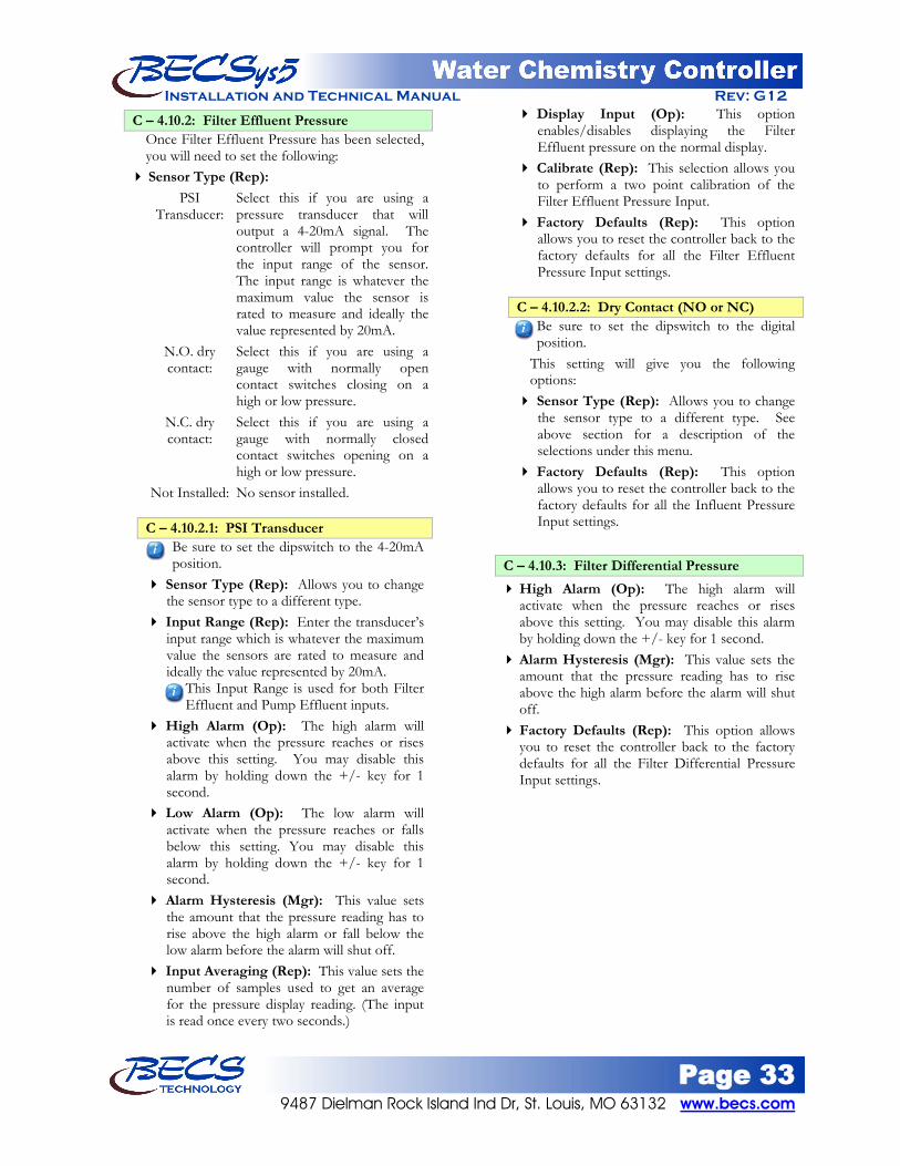
Page 33 9487 Dielman Rock Island Ind Dr, St. Louis, MO 63132 www.becs.com
Installation and Technical Manual Rev: G12
C – 4.10.2: Filter Effluent Pressure Once Filter Effluent Pressure has been selected, you will need to set the following:
Sensor Type (Rep): PSI
Transducer: Select this if you are using a pressure transducer that will output a 4-20mA signal. The controller will prompt you for the input range of the sensor. The input range is whatever the maximum value the sensor is rated to measure and ideally the value represented by 20mA.
N.O. dry contact:
Select this if you are using a gauge with normally open contact switches closing on a high or low pressure.
N.C. dry contact:
Select this if you are using a gauge with normally closed contact switches opening on a high or low pressure.
Not Installed: No sensor installed.
C – 4.10.2.1: PSI Transducer Be sure to set the dipswitch to the 4-20mA position.
Sensor Type (Rep): Allows you to change the sensor type to a different type.
Input Range (Rep): Enter the transducer’s input range which is whatever the maximum value the sensors are rated to measure and ideally the value represented by 20mA.
This Input Range is used for both Filter Effluent and Pump Effluent inputs.
High Alarm (Op): The high alarm will activate when the pressure reaches or rises above this setting. You may disable this alarm by holding down the +/- key for 1 second.
Low Alarm (Op): The low alarm will activate when the pressure reaches or falls below this setting. You may disable this alarm by holding down the +/- key for 1 second.
Alarm Hysteresis (Mgr): This value sets the amount that the pressure reading has to rise above the high alarm or fall below the low alarm before the alarm will shut off.
Input Averaging (Rep): This value sets the number of samples used to get an average for the pressure display reading. (The input is read once every two seconds.)
Display Input (Op): This option enables/disables displaying the Filter Effluent pressure on the normal display.
Calibrate (Rep): This selection allows you to perform a two point calibration of the Filter Effluent Pressure Input.
Factory Defaults (Rep): This option allows you to reset the controller back to the factory defaults for all the Filter Effluent Pressure Input settings.
C – 4.10.2.2: Dry Contact (NO or NC)
Be sure to set the dipswitch to the digital position.
This setting will give you the following options: Sensor Type (Rep): Allows you to change
the sensor type to a different type. See above section for a description of the selections under this menu.
Factory Defaults (Rep): This option allows you to reset the controller back to the factory defaults for all the Influent Pressure Input settings.
C – 4.10.3: Filter Differential Pressure High Alarm (Op): The high alarm will
activate when the pressure reaches or rises above this setting. You may disable this alarm by holding down the +/- key for 1 second.
Alarm Hysteresis (Mgr): This value sets the amount that the pressure reading has to rise above the high alarm before the alarm will shut off.
Factory Defaults (Rep): This option allows you to reset the controller back to the factory defaults for all the Filter Differential Pressure Input settings.
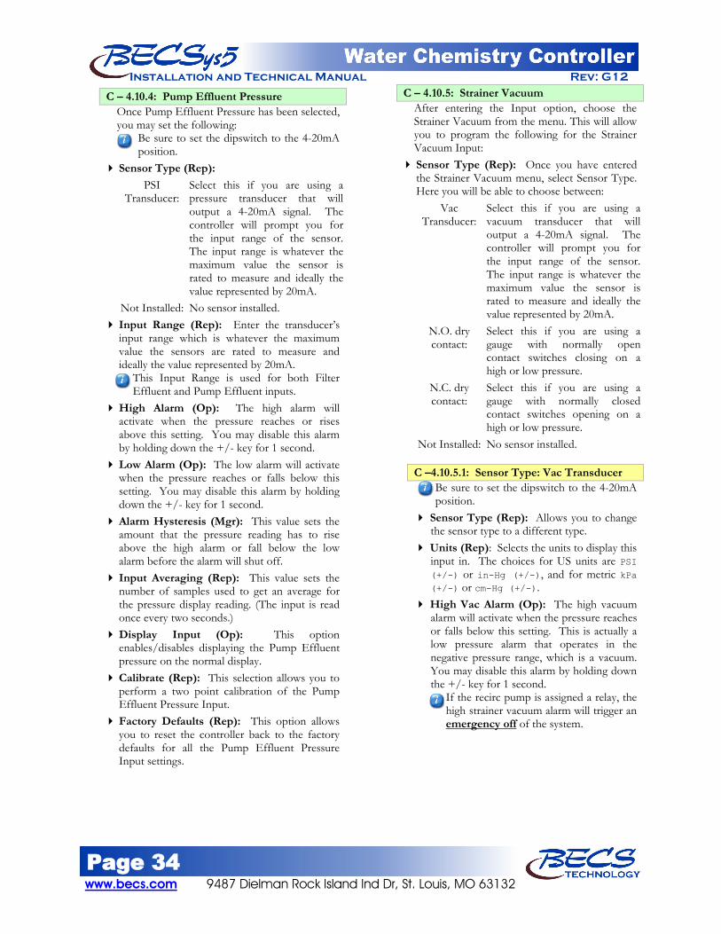
Page 34 www.becs.com 9487 Dielman Rock Island Ind Dr, St. Louis, MO 63132
Installation and Technical Manual Rev: G12
C – 4.10.4: Pump Effluent Pressure Once Pump Effluent Pressure has been selected, you may set the following:
Be sure to set the dipswitch to the 4-20mA position.
Sensor Type (Rep): PSI
Transducer: Select this if you are using a pressure transducer that will output a 4-20mA signal. The controller will prompt you for the input range of the sensor. The input range is whatever the maximum value the sensor is rated to measure and ideally the value represented by 20mA.
Not Installed: No sensor installed. Input Range (Rep): Enter the transducer’s
input range which is whatever the maximum value the sensors are rated to measure and ideally the value represented by 20mA.
This Input Range is used for both Filter Effluent and Pump Effluent inputs.
High Alarm (Op): The high alarm will activate when the pressure reaches or rises above this setting. You may disable this alarm by holding down the +/- key for 1 second.
Low Alarm (Op): The low alarm will activate when the pressure reaches or falls below this setting. You may disable this alarm by holding down the +/- key for 1 second.
Alarm Hysteresis (Mgr): This value sets the amount that the pressure reading has to rise above the high alarm or fall below the low alarm before the alarm will shut off.
Input Averaging (Rep): This value sets the number of samples used to get an average for the pressure display reading. (The input is read once every two seconds.)
Display Input (Op): This option enables/disables displaying the Pump Effluent pressure on the normal display.
Calibrate (Rep): This selection allows you to perform a two point calibration of the Pump Effluent Pressure Input.
Factory Defaults (Rep): This option allows you to reset the controller back to the factory defaults for all the Pump Effluent Pressure Input settings.
C – 4.10.5: Strainer Vacuum After entering the Input option, choose the Strainer Vacuum from the menu. This will allow you to program the following for the Strainer Vacuum Input:
Sensor Type (Rep): Once you have entered the Strainer Vacuum menu, select Sensor Type. Here you will be able to choose between:
Vac Transducer:
Select this if you are using a vacuum transducer that will output a 4-20mA signal. The controller will prompt you for the input range of the sensor. The input range is whatever the maximum value the sensor is rated to measure and ideally the value represented by 20mA.
N.O. dry contact:
Select this if you are using a gauge with normally open contact switches closing on a high or low pressure.
N.C. dry contact:
Select this if you are using a gauge with normally closed contact switches opening on a high or low pressure.
Not Installed: No sensor installed.
C –4.10.5.1: Sensor Type: Vac Transducer Be sure to set the dipswitch to the 4-20mA position.
Sensor Type (Rep): Allows you to change the sensor type to a different type.
Units (Rep): Selects the units to display this input in. The choices for US units are PSI (+/-) or in-Hg (+/-), and for metric kPa (+/-) or cm-Hg (+/-).
High Vac Alarm (Op): The high vacuum alarm will activate when the pressure reaches or falls below this setting. This is actually a low pressure alarm that operates in the negative pressure range, which is a vacuum. You may disable this alarm by holding down the +/- key for 1 second.
If the recirc pump is assigned a relay, the high strainer vacuum alarm will trigger an emergency off
of the system.

Page 35 9487 Dielman Rock Island Ind Dr, St. Louis, MO 63132 www.becs.com
Installation and Technical Manual Rev: G12 High Vac Warning (Op): The high
vacuum warning will activate when the pressure reaches or falls below this setting. This is actually a low pressure alarm that operates in the negative pressure range, which is a vacuum. You may disable this alarm by holding down the +/- key for 1 second.
The high strainer vacuum warning is generally used to indicate to the operators that the strainer needs cleaned. While this warning does flash the alarm LED, it does not shut down any pumps or feeds.
Alarm Hysteresis (Mgr): This value sets the level that the pressure reading must rise above the alarm settings before the alarm will shut off.
Input Averaging (Rep): This value sets the number of samples used to get an average for the vacuum display reading. (The input is read once every two seconds.)
Calibrate (Rep): Perform a two point calibration of the Strainer Vacuum Input.
Factory Defaults (Rep): This option allows you to reset the controller back to the factory defaults for all the Strainer Vacuum Input settings.
C – 4.10.5.2: Sensor Type: dry contact (NO or NC)
Be sure to set the dipswitch to the digital position.
Sensor Type (Rep): Allows you to change the sensor type to a different type.
Factory Defaults (Rep): This option allows you to reset the controller back to the factory defaults for all the Strainer Vacuum Input settings.
C – 4.10.6: Total Dynamic Head This menu is only shown if the Strainer and either the Filter Influent's or Pump Effluent's Sensor Types are set to transducer types.
Pump Effluent Pressure is used for the TDH calculation if both the Filter Influent and Pump Effluent inputs are configured to use transducer sensors.
Display TDH (Op): Enables displaying total dynamic head on the normal display.
High Alarm (Op): The high alarm will activate when the total dynamic head across the pump reaches or rises above this setting. You may disable this alarm by holding down the +/- key for 1 second.
Low Alarm (Op): The low alarm will activate when the total dynamic head across the pump reaches or falls below this setting. You may disable this alarm by holding down the +/- key for 1 second.
Alarm Hysteresis (Mgr): This value sets the amount that the total dynamic head has to rise above the high alarm or fall below the low alarm before the alarm will shut off.
Factory Defaults (Rep): This option allows you to reset the controller back to the factory defaults for all the total dynamic head settings.

Page 36 www.becs.com 9487 Dielman Rock Island Ind Dr, St. Louis, MO 63132
Installation and Technical Manual Rev: G12
C – 5: Control Outputs C – 5.1: Assign Relays
(Rep) To enable control functions, you must assign that function a relay. Control functions are broken up into two groups; Sanitization Feeds and Other Feeds. To set or change the relay used or to disable a control, press the Menu button, then select Control Outputs, Assign Relays, select the group the control function is listed under (see below), and then the control function itself. This will display all of the relays available to be assigned to this control, including the current relay if one was already assigned. Select the relay you wish to assign to the control function or select Disable function to disable the function and free up the currently assigned relay. For information on configuring a particular control, see that control's section in this manual. The following lists the different control functions under each category and a brief description:
C – 5.1.1 - Sanitization feeds Cl Feed - This is your primary Cl feed. Cl Booster - The Cl Booster is a highly
programmable secondary Cl feed for helping maintain the ORP and/or free Cl levels of the pool during high bather loads. This feed also runs during Super Chlorination cycles, and is locked out by the Cl (Br) failsafe alarm.
SuperChlor - The Super Chlorination (shock) function is unique to the other control functions in the sense that you can either assign its own relay [for controlling an additional chlorine feed or a non-chlorine shock chemical feed], or assign it to the primary Cl feed's relay if an additional feeder is not used. SuperChlor will always override and run the primary Cl feed and the Cl booster feed, if enabled, in order to help bring the ORP or free Cl level up to the superChlor set point.
DeChlor - The DeChlor feature is only shown if SuperChlor has been assigned a relay. DeChlor is intended to be used following a super chlorination to bring the ORP and/or free Cl level back down to a safe level.
Ozone - The Ozone feed is a highly programmable feed similar to the Cl booster, but is not limited by the Cl failsafe or forced to operate during a Super Chlorination cycle.
UV Turndown – this control activates a relay to turn down a UV unit prior to recirculation shutdown and filter backwash and optionally control to a combined chlorine set point.
C – 5.1.2 - Other Feeds pH feeds - Two pH feeds are available for use.
If both feed directions are used, they will work together to maintain a single set point. To switch the pH feed direction, you must set the current pH function's relay to disabled and assign that relay to the other pH function.
Heater - The heater control allows you to control the heater to a different set point at different times of the day, automatically shut down during no flow or low flow alarms, interlock with the recirculation pump and backwash (fireman switch).
Polymer Feed - The polymer feed uses the turbidity input or a cycle timer to determine when to add polymer to the water to increase the filtration power of your filters.
Autofill - The Autofill control operates a makeup water valve to add water to your pool. It uses either or one or two proximity switches or the Surge Pit 4-20mA Input with programmable alternate set point to control to a different level while, for example, feature pumps are running.
TDS Control - The TDS control works with the Autofill control or an independent Autofill device to lower the TDS of the pool by operating a drain valve to drain water while the Autofill adds fresh water - requires the conductivity/TDS sensor.
Sensor Wash - Sensor Wash is a rename-able programmable cycle timer with four separate schedules that is usually used to trigger an acid feed wash to clean the pH and ORP probes.
Enzyme Feed – this is rename-able programmable daily cycle timer.
Recirculation Pump - The recirculation pump control is used to shutdown the recirculation pump under certain alarm conditions and by the powersaver control option.
Alarm Relay - The Alarm Relay triggers whenever there is an active alarm or while the emergency off feature is active.

Page 37 9487 Dielman Rock Island Ind Dr, St. Louis, MO 63132 www.becs.com
Installation and Technical Manual Rev: G12 C – 5.2: pH Control
By default, the pH feed down control is assigned to relay 1. To switch to pH feed up control, disable the pH feed down by unassigning its relay and then assign the relay to the pH feed down control. See Section 5.1. To enable dual pH control (feed up and feed down), assign a relay to both pH feed up and pH feed down controls. After entering the Control Outputs option, select pH Control from the menu. This will allow for the programming of the following for the pH control:
Control Type (Op): Choose from On/Off or Time Base Proportional control.
In general, if you are using a motor driven chemical feeder then you should choose the On/Off option. If you are using a solenoid driven or pulsed diaphragm chemical feeder (such as Pulsatron, most LMI models or most Prominent Models), you should choose the TBP option. This feature helps to hold a set point and to minimize over-shoot by making a standard feeder mimic the action of more sophisticated modulating feeders. If you choose the On/Off option and are feeding up, then the controller will activate the chemical feeder whenever the pH falls below the set point and continue to feed until the pH rises above the set point plus hysteresis at which point it will stop. If you choose the TBP option and are feeding up then the controller will activate the chemical feeder whenever the pH falls below the set point and will feed for a percentage of the Time Base (default one minute) proportional to the offset from set point. For the remainder of the Time Base the feeder will be paused. The feeder will continue this feed and pause cycle until the controller achieves the set point plus hysteresis. The closer to set point, the less time the feeder is ON.
Set Point (Op): This value sets the desired level to maintain the pH at. Input the desired pH set point.
Span/Prop. Bnd (Op): This option is only shown if the Control Type is Time Base Proportional. This value sets the distance (or span) from the set point that the output will be proportionally controlled.
Time Base (Op): This option is only shown if the Control Type is Time Base Proportional. This sets the total time that control is based on. During this time, the feeder will turn on for a percentage of the Time Base and turn off for the remainder.
Minimum On Time (Rep): This value is the minimum time the pump will be on during Time Base Proportional control. This helps protect the feeder from cycling on or off for too short a period of time.
Failsafe Timer (Op): This value sets the time that the relay is allowed to stay continuously on.
The most common failures of automated chemical feed systems are depletion of the chemical supply and/or chemical feeder failure. Both problems result in the controller being unable to reach set point in a reasonable period of time. The failsafe timer sets the maximum length of time the feeder can run. If the feeder has been trying to achieve set point without success for the selected time, the controller will cut power to the feeder, flash the Reset Fail/Safe LED on the face panel and display a message to alert the operator. If in TBP Pause mode, the controller will reset the timer. An operator must reset the failsafe through the Reset Fail/Safe button to re-enable normal control.
Hysteresis (Rep): This value sets the amount the input must rise above (feed up) or fall below (feed down) the set point before the feed is shut off. (the range is from 0.0 to 1.4)
Dead Band (Mgr): This option is only shown under dual pH control. This value sets the amount the input must exceed the set point by before the feed of the opposite direction will trigger. (The range is from twice the feeds' hysteresis to 2.8 pH)
Warning: Disabling the failsafe timers is highly discouraged. They are an important safety feature to protect against dangerous
chemical overfeeds and will protect the equipment from running continuously if it runs
out of chemical.
Warning: Increasing or decreasing the Span/Prop. band or Time Base may cause the feed to severely overshoot or never achieve set point.
Adjust this option only when recommended to do so by a factory representative.

Page 38 www.becs.com 9487 Dielman Rock Island Ind Dr, St. Louis, MO 63132
Installation and Technical Manual Rev: G12 C – 5.3: Chlorine Control
After entering the Control Outputs option, select the Cl Control from the menu. This will allow the programming of the following:
Sanitizer Chemical (Op): Sets the sanitizer chemical name (Chlorine or Bromine).
This option controls what chemical name the controller displays for the Cl inputs and the primary sanitization/oxidizing chemical.
Control Input Src (Op): This option is only available if the free Cl Input source is set to Calculated or Probe. Choose between ORP and free Cl to use as the primary control input for the sanitizer feed.
If the free Cl Input is selected and the free Cl Input source is set to probe, ORP is still used for control while the free Cl interlock timer is running. If the free Cl Input is selected and the free Cl Input source is set to calculated, the controller still controls off of ORP, but the ORP set point is calculated by the controller based on the free Cl set point, the pH set point, and the free Cl calibration. Modification of any one of those three values will result in a new ORP set point.
Control Type (Op): Choose from On/Off or Time Base Proportional control.
In general, if you are using a motor driven chemical feeder then you should choose the On/Off option. If you are using a solenoid driven or pulsed diaphragm chemical feeder (such as Pulsatron, most LMI models or most Prominent Models), you should choose the TBP option. This feature helps to hold a set point and to minimize over-shoot by making a standard feeder mimic the action of more sophisticated modulating feeders. If you choose the On/Off option, then the controller will activate the chemical feeder whenever the ORP falls below the set point and continue to feed until the ORP rises above the set point plus hysteresis at which point it will stop. If you choose the TBP option, then the controller will activate the chemical feeder whenever the ORP falls below the set point and will feed for a percentage of the Time Base (default one minute) proportional to the offset from set point. For the remainder of the Time Base the feeder will be paused. The feeder will continue this feed and pause cycle until the controller achieves the set point plus hysteresis. The closer to set point, the less time the feeder is ON.
ORP Set Point (Op): This option is NOT shown if the Control Source is set to free Cl and the free Cl Input source is set to Calculated. This value sets the desired level to maintain the ORP at.
ORP Span/Prop. Bnd (Op): This option is only shown if the Control Type is Time Base Proportional and the ORP Set Point is shown above. This value sets the distance (or span) from the set point that the output will be proportionally controlled.
Free Cl Span/Prop Bnd (Op): This option is only shown if the Control Type is Time Base Proportional, the Control Source is set to free Cl, and the free Cl Input source is set to probe. This value sets the distance (or span) from the set point that the output will be proportionally controlled.
Free Cl Set Point (Op): This option is only shown if the Control Source is set to free Cl. This value sets the desired level to maintain the free Cl at.
Free Cl Ctrl Hyst (Rep): This option is only shown if the Control Source is set to free Cl and the free Cl Input source is set to probe. This value sets the amount the input must rise above set point before the feed will shut off.
Time Base (Op): This option is only shown if the Control Type is Time Base Proportional. This sets the total time that control is based on. During this time, the feeder will turn on for a percentage of the Time Base and turn off for the remainder.
Minimum On Time (Rep): This option is only shown if the Control Type is Time Base Proportional. This value is the minimum time the pump will be on during Time Proportional control. This helps protect the feeder from cycling on or off for too short a period of time.
Warning: Increasing or decreasing the time base may cause the feed to severely overshoot or never achieve set point. Adjust this option only when recommended to do so by a factory
representative.
Warning: Increasing or decreasing the proportional band may cause the feed to
severely overshoot or never achieve set point. Adjust this option only when recommended to
do so by a factory representative.

Page 39 9487 Dielman Rock Island Ind Dr, St. Louis, MO 63132 www.becs.com
Installation and Technical Manual Rev: G12 C – 5.3: Chlorine Control (continued) Failsafe Timer (Op): This value sets the time
that the relay is allowed to stay continuously on. The most common failures of automated chemical feed systems are depletion of the chemical supply and/or chemical feeder failure. Both problems result in the controller being unable to reach set point in a reasonable period of time. The failsafe timer sets the maximum length of time the feeder can run. If the feeder has been trying to achieve set point without success for the selected time, the controller will cut power to the feeder, flash the Reset Fail/Safe LED on the face panel and display a message to alert the operator. If in TBP Pause mode, the controller will reset the timer. An operator must reset the failsafe through the Reset Fail/safe button to re-enable normal control.
Alt Set Point (Op): The 4 Event 28 Day Timer allows you to program a schedule to define when to use alternate set point. Alt Set Point 4 Event 28 Day Timer: To
program the 4 Event 28 Day Timer, perform the following: • Select the Alt. Set point from the Cl (Br)
Control menu. • Now select the 4Event 28Day Timer from the
Alt. Set Point menu. • Selecting Event1 will allow you to select the
weekly interval to use the alternate set point. If the 1st, 2nd, 3rd, or 4th week is selected, the timer will only trigger on that week in the four-week cycle. The Odd Weeks selection will trigger on the 1st and 3rd weeks, the Even Weeks selection will trigger on the 2nd and 4th weeks, and the Every Week selection triggers every week.
The week number and day of week for the current date is displayed on the bottom right side of these screens. The first week is fixed to be the week of Sunday, January 2nd, 2000 and every four weeks afterwards.
The next set of screens will allow you to choose the actual day(s).
• Select what day of the week, or every day, the alternate set point should be used.
• Once you make your selection you will be returned to the 4Event 28Day Timer menu where you will have a new menu item: Event 1 Times.
• Select the Event1 Times from the 4Event 28Day Timer menu. This screen allows you to set both the start time and the end time for the event's programmed weeks/days. To toggle AM/PM, press the +/- key while the cursor is on the time you wish to change.
If your start time is before midnight (12:00 AM) and the end time is after midnight, the alternate set point will continue to be used the following day up to the end time even if that day did not fall within the week/day selection for that event.
Example: Event1 Week/Day: Odd weeks/ Tuesday Event1 Times: 11:00 PM to 3:00 AM Event2 Week/Day: Even weeks/ Monday Event2 Times: 11:00 PM to 6:00 AM Current Week/Day: 2nd/Tuesday Current Time: 4:00 PM The alternate set point last ran from 11:00 PM
last night to 6:00AM this morning. The next time the alternate set point will run will
be from 11:00 PM next Tuesday to 3:00AM next Wednesday.
ORP Set Point (Op): This value sets the desired level to maintain the ORP at during any of the programmed alternate set point events.
Free Cl Set Point (Op): This option is only available if the free Cl probe is installed and the Control Source is set to free Cl. This value sets the desired level to maintain the free Cl at during any of the programmed alternate set point events.
Bracketed Free Cl (Op): This option is only available if the free Cl probe is installed and the Control Source is set to ORP. If enabled, the controller will override the ORP control so that the free Cl will not drop out of a programmed range.
Bracketed ORP (Op): This option is only available if the free Cl probe is installed and the Control Source is set to free Cl. If enabled, the controller will override the free Cl control so that the ORP will not drop out of a programmed range.
Warning: Disabling the failsafe timers is highly discouraged. They are an important safety feature to protect against dangerous
chemical overfeeds and will protect the equipment from running continuously if it runs
out of chemical.

Page 40 www.becs.com 9487 Dielman Rock Island Ind Dr, St. Louis, MO 63132
Installation and Technical Manual Rev: G12 C – 5.4: Chlorine Booster Control
After entering the Control Outputs option, select the Cl Booster Ctrl from the menu. This will allow the programming of the following:
Control Input (Op): This option is only available if the free Cl Input is enabled. Choose between ORP, free Cl or, if the free Cl probe is used, both to control the chlorine booster.
ORP Trigger Point (Op): This option is only shown if the Control Input is ORP or Both. This value sets the ORP level that the input must drop below to activate the chlorine booster control. (the range is –1000 mV to the Cl Booster's ORP Set Point)
Free Cl Trigger Point (Op): This option is only shown if the Control Input is free Cl or Both. This value sets the free Cl level that the input must drop below to activate the chlorine booster control. (the range is from 0.0 free Cl to the Cl Booster's free Cl Set Point)
ORP Set Point (Op): This option is only shown if the Control Input is ORP or Both. This value sets the ORP level that once it is reached the chlorine booster control will shut off. (the range is from Cl Booster's ORP Trigger Point to the ORP high alarm point)
Free Cl Set Point (Op): This option is only shown if the Control Input is free Cl or Both. This value sets the free Cl level that once it is reached the chlorine booster control will shut off. (the range is from the Cl Booster's free Cl Trigger Point to the free Cl high alarm point)
ORP Hysteresis (Rep): This option is only shown if the Control Input is ORP, Both, or, if free Cl Input source is set to calculated, free Cl. This value sets the level that the input must rise above the set point before the chlorine booster control will turn off.
Free Cl Hysteresis (Rep): This option is only shown if the free Cl probe is used and the Control Input is free Cl or Both. This value sets the level that the input must rise above the set point before the chlorine booster control will turn off.
Label (Rep): Allows you to change the name of this control. There is a 12 character maximum.
Failsafe Timer (Op): This value sets the time that the relay is allowed to stay continuously on.
The most common failures of automated chemical feed systems are depletion of the chemical supply and/or chemical feeder failure. Both problems result in the controller being unable to reach set point in a reasonable period of time. The failsafe timer sets the maximum length of time the feeder can run. If the feeder has been trying to achieve set point without success for the selected time, the controller will cut power to the feeder, flash the Reset Fail/Safe LED on the face panel and display a message to alert the operator. If in TBP Pause mode, the controller will reset the timer. An operator must reset the failsafe through the Reset Fail/Safe button to re-enable normal control.
Factory Defaults (Rep): This option allows you to reset the controller back to the factory defaults for all of the Cl Booster Control settings.
Warning: Disabling the failsafe timers is highly discouraged. They are an important safety feature to protect against dangerous
chemical overfeeds and will protect the equipment from running continuously if it
runs out of chemical.

Page 41 9487 Dielman Rock Island Ind Dr, St. Louis, MO 63132 www.becs.com
Installation and Technical Manual Rev: G12 C – 5.5: Super Chlorination
After entering the Control Outputs option, select Super Chlorination from the menu. This will allow the programming of the following:
Control Input (Op): This option is only available if the free Cl probe is installed. Choose between free Cl and ORP to use to control the Super Chlorination feed.
4 Event 28 Day Timer (Op): To program when the super chlorination should trigger, select 4Event 28Day Timer from the Super Chlorination menu: Selecting Event1 will allow you to select the
weekly interval to trigger the Super Chlorination. If the 1st, 2nd, 3rd, or 4th week is selected, the timer will only trigger on that week in the four-week cycle. The Odd Weeks selection will trigger on the 1st and 3rd weeks, the Even Weeks selection will trigger on the 2nd and 4th weeks, and the Every Week selection triggers every week.
The week number and day of week for the current date is displayed on the bottom right side of these screens. The first week is fixed to be the week of Sunday, January 2nd, 2000 and every four weeks afterwards.
Next you can select the day of the week (or
every day) the event should be triggered on.
Once you make your selection, you will be returned to the 4Event 28Day Timer menu where you will have a new menu item: Event 1 Start Time.
Select the Event1 Start Time from the 4Event
28Day Timer menu. This screen allows you to set the time to trigger the event on the programmed weeks/days. The event will trigger at the start time if the controller is running at that time. To toggle AM/PM, press the +/- key. Enter the desired time and press enter. After setting the time, press the left arrow to return to Super Chlorination's main menu. Here you will notice the next scheduled super chlorination is displayed for you. The controller will also list the last super chlorination here once one has been completed.
Maximum Time On (Op): This value sets the maximum time you want the Super Chlorination on to reach the set point. If the time expires before set point is reached, the controller will trigger the SuperChlor failsafe alarm and end the
SuperChlor feeds. (the range is from 0:00 to 18:00 hours)
An operator can reset the failsafe through the Reset Fail/Safe button; however the failsafe alarm will automatically clear itself when the regular Cl feed begins feeding.
ORP Set Point (Op): This option is only shown if the Control Input is set to ORP. This value sets the desired ORP level to shock the pool.
Free Cl Set Point (Op): This option is only shown if the Control Input is set to free Cl. This value sets the desired free Cl level to shock the pool.
Factory Defaults (Rep): This option allows you to reset the controller back to the factory defaults for all of the Super Chlorination settings.
C – 5.6: Dechlorination After entering the Control Outputs option, select Dechlorination from the menu. This will allow the programming of the following:
Control Input (Op): This option is only available if the free Cl probe is installed. Choose between free Cl and ORP to use to control the dechlor feed.
Follow Super Chlorination (Op): Choose whether or not you want your dechlorination to automatically follow your super chlorination.
4 Event 28 Day Timer (Op): The 4 Event 28 Day Timer allows you to program the dechlorination on a schedule. See the section on Super Chlorination's 4 Event 28 Day Timer for details on how to set this.
Maximum Time On (Op): This value sets the maximum time you want the dechlorination on to reach the set point. (the range is from 0:00 to 18:00 hours)
ORP Set Point (Op): This option is only shown if the Control Input is set to ORP. This value sets the desired final ORP level.
Free Cl Set Point (Op): This option is only shown if the Control Input is set to free Cl. This value sets the desired final free Cl level.
Factory Defaults (Rep): This option allows you to reset the controller back to the factory defaults for all of the dechlorination settings.

Page 42 www.becs.com 9487 Dielman Rock Island Ind Dr, St. Louis, MO 63132
Installation and Technical Manual Rev: G12 C – 5.7: Ozone Control
After entering the Control Outputs option, select Ozone Control from the menu. This will allow the programming of the following:
Control Input (Op): This option is only available if the free Cl probe is installed. Choose between free Cl, ORP, or both to use to control the Ozone feed.
ORP Set Point (Op): This option is only shown if the Control Input is ORP or Both. This value sets the ORP level that the input must drop below to activate the Ozone.
Free Cl Set Point (Op): This option is only shown if the Control Input is free Cl or Both. This value sets the free Cl level that the input must drop below to activate the Ozone.
ORP Hysteresis (Rep): This option is only shown if the Control Input is ORP or Both. This value sets the level that the input must rise above the set point before the Ozone control will turn off the relay.
Free Cl Hysteresis (Rep): This option is only shown if the Control Input is free Cl or Both. This value sets the level that the input must rise above the set point before the Ozone control will turn off the relay.
Fireman Switch (Op): This option is only shown if a relay is assigned to the recirculation pump or backwash. This value sets the minimum amount of time to leave the recirculation pump on or delay the start of backwash after the Ozone relay shuts off.
Label (Rep): Allows you to change the name of this control. There is a 12 character maximum.
Failsafe Timer (Op): This value sets the time that the relay is allowed to stay continuously on.
Factory Defaults (Rep): This option allows you to reset the controller back to the factory defaults for all of the Ozone Control settings.
C – 5.8: Heater After entering the Control Outputs option, select Heater Control from the menu. This will allow the programming of the following:
Temp. Ctrl Enable (Op): Enables or disables controlling the Heater using the Temperature Input.
Set Point (Op): Only shown if Temp. Ctrl is enabled. This value sets the desired temperature. (the range is from the temperature low alarm to the temperature high alarm)
Failsafe Timer (Op): Only shown if Temp. Ctrl is enabled. This value sets the time that the relay is allowed to stay on without reaching set point before the relay is locked out. If the heater has been trying to achieve set point without success for the selected time, the controller will cut power to the heater, flash the Reset Fail/Safe LED on the face panel and display a message to alert the operator.
An operator must reset the failsafe through the Reset Fail/safe button to re-enable normal control.
Minimum Flow Rate (Rep): This option is only shown if the flow rate input is enabled. When set to a non-zero value, the heater will be shut down if flow rate drops below this set point. To prevent the heater to constantly be switched on and off due to a fluctuating flow rate, the flow rate must stay above or below the set point for a full thirty seconds before the heater is re-enabled or shut down.
Fireman Switch (Op): This option is only shown if a relay is assigned to the recirculation pump or backwash. This value sets the minimum amount of time to leave the recirculation pump on or delay the start of backwash after the heater relay shuts off.
Hysteresis (Rep): Only shown if Temp. Ctrl is enabled. This value sets the level that the input must rise above the set point before the heater control will turn off.
Alternate Temperature (Op): Only shown if Temp. Ctrl is enabled. The 4 Event 28 Day Timer allows you to program an alternate set point on a schedule. See the Chlorine (Bromine) Control's Alt Set Point for details on how to set this. After the schedule is set, you may choose the alternate temperature set point option and enter the desired setting.
Factory Defaults (Rep): This option allows you to reset the controller back to the factory defaults for all of the Heater settings.

Page 43 9487 Dielman Rock Island Ind Dr, St. Louis, MO 63132 www.becs.com
Installation and Technical Manual Rev: G12 C – 5.9: Autofill
This menu item is only available if the Surge Pit is set to 4-20mA Input, or if the Autofill 1 and optionally Autofill 2 inputs have been installed. After entering the Control Outputs option, select Autofill from the menu. This will allow the programming of the following:
Control Source (Rep): Surge Pit Level: Allows the Autofill to be
triggered from the Surge Pit Level 4-20mA input.
N.O. prox switch: Select this if you are using one or two proximity switches with normally open contacts to control autofill.
N.C. prox switch: Select this if you are using one or two proximity switches with normally closed contacts to control autofill
Not Installed: No sensor installed. Set Point (Op): Only shown if Autofill sensor type is
set to Surge Pit Level. This value sets the surge pit level that the controller will fill to.
Alternate Set Point (Op): Only shown if Autofill sensor type is set to Surge Pit Level. To program when to use the alternate set point, see the section on Chlorine (Bromine) Control’s Alternate Set point Timer Settings. After the schedule is set, you may choose the alternate set point option and enter the desired setting.
Start Delay (Op): Sets the time required for the water level to stay below the trigger point before fill begins.
End Delay (Op): Sets the time required for the water level to remain above shutoff point before ending the fill.
Hysteresis (Rep): Only shown if Autofill sensor type is set to Surge Pit Level. This value sets the level that the input must rise above the set point before the Autofill will close the valve.
Failsafe Timer (Op): This value sets the time that the relay is allowed to stay on without reaching set point before the relay is locked out. If Autofill has been trying to achieve set point without success for the selected time, the controller will cut power to the relay, flash the Reset Fail/Safe LED on the face panel and display a message to alert the operator.
An operator must reset the failsafe through the Reset Fail/safe button to re-enable normal control.
Factory Defaults (Rep): This option allows you to reset the controller back to the factory defaults for all of the Autofill settings.
C – 5.10: TDS Control After entering the Control Outputs option, select TDS Control from the menu. This will allow the programming of the following:
Makeup water TDS (Op): Enter the test kit TDS reading for the water controlled by your Autofill. This is used to determine the appropriate TDS set point.
Pool TDS cycle (Op): Enter the pools' cycle multiplier of the incoming makeup water. The resulting TDS set point is the incoming makeup water's TDS times this value.
Hysteresis (Rep): This value sets the level that the TDS Input must fall below the set point before the TDS control will close the drain valve.
Failsafe Timer (Op): This value sets the time that the relay is allowed to stay on without reaching set point before the relay is locked out. If the TDS control has been trying to achieve set point without success for the selected time, the controller will cut power to the relay, flash the Reset Fail/Safe LED on the face panel and display a message to alert the operator.
An operator must reset the failsafe through the Reset Fail/safe button to re-enable normal control.
Factory Defaults (Rep): This option allows you to reset the controller back to the factory defaults for all of the TDS Control settings.
C – 5.11: Sensor Wash 4 Event 28 Day Timer (Op): Once you have
entered Sensor Wash, select 4Event 28Day Timer from the menu. The 4 Event 28 Day Timer allows you to program the sensor wash on a schedule. See the section on Super Chlorination's 4 Event 28 Day Timer for details on how to set this. Start/End Time (Op): Allows you to set
what times the feed may be triggered during a day.
# Of Cycles (Op): Only shown if Duration is not zero. Sets how many times the relay will trigger between the Start and End times.
Duration (Op): Sets how long the feed will run for each cycle. If set to zero, there are no cycles and the relay will simply be on when current time is between the active event's start and end times.
Label (Rep): Allows you to change the name of this control. There is a 12 character maximum.
Factory Defaults (Rep): This option allows you to reset the controller back to the factory defaults for all of the Sensor Wash settings.

Page 44 www.becs.com 9487 Dielman Rock Island Ind Dr, St. Louis, MO 63132
Installation and Technical Manual Rev: G12 C – 5.12: Enzyme
After entering the Control Outputs option, select Enzyme from the menu. This will allow the programming of the following:
Start/End Time (Op): Allows you to set what times the feed may be triggered during a day.
# Of Cycles (Op): Only shown if Duration is not zero. Sets how many times the relay will trigger between the Start and End times.
Duration (Op): Sets how long the feed will run for each cycle. If set to zero, there are no cycles and the relay will simply be on when current time is between the start and end times.
Label (Rep): Allows you to change the name of this control. There is a 12 character maximum.
Factory Defaults (Rep): This option allows you to reset the controller back to the factory defaults for the Enzyme feed settings.
C – 5.13: Polymer After entering the Control Outputs option, select Polymer Control from the menu. This will allow the programming of the following:
The polymer feed will not trigger until 10 minutes after the last backwash cycle.
Control Type (Rep): Select whether to control the polymer feed either by the turbidity input or by a cycle timer.
When Turbidity Control is selected, the polymer feed will not trigger until the turbidity reading remains above the High Set Point for the Trigger Delay Time. At the beginning of each cycle, the relay turns on, stays on for the programmed On Time, then shuts off for the remainder of the cycle time. The control cycle will repeat until the Low Set Point is achieved. When Cycle Timer is selected, polymer is fed "# of cycles" times a day between the start and end time for the programmed duration.
High Set Point (Op): Only shown if control type is set to Turbidity Control. When the turbidity reading rises above this value for the Trigger Delay Time, the controller will trigger the polymer control cycle.
Low Set Point (Op): Only shown if control type is set to Turbidity Control. At the end of each 10 minute control cycle, the controller checks to see if the turbidity reading is below this value. If it is, the control cycle ends, otherwise the controller starts a new control cycle.
Cycle Time (Op): Only shown if control type is set to Turbidity Control. This value sets the control cycle duration. At the beginning of each cycle, the relay
turns on, stays on for the programmed On Time, then shuts off for the remainder of the cycle time.
On Time (Op): Only shown if control type is set to Turbidity Control. This value sets how long the controller will feed polymer during each control cycle.
Trigger Delay Time (Op): Only shown if control type is set to Turbidity Control. This value sets how long the turbidity reading must remain above the high set point before triggering the polymer control cycle.
Start/End Time (Op): Only shown if control type is set to Cycle Timer. Allows you to set what times the feed may be triggered during a day.
# Of Cycles (Op): Only shown if control type is set to Cycle Timer and duration is not 0. Sets how many times the feed will be triggered between the Start and End times.
Duration (Op): Only shown if control type is set to Cycle Timer. Sets how long the feed will run for each cycle. If set to zero, there are no cycles and the relay will simply be on when current time is between the start and end times.
Factory Defaults (Rep): This option allows you to reset the controller back to the factory defaults for all of the Polymer Control settings.
C – 5.14: UV Turndown After entering the Control Outputs option, select UV Turndown from the menu. This will allow the programming of the following:
Combined Cl Set Point (Op): This option is only shown if both the free Cl and total Cl probes are installed. This value sets the Combined Cl level that the input must be equal to or drop below to activate the turndown.
Start Delay (Op): This option is only shown if both the free Cl and total Cl probes are installed. Time the combined free Cl must remain at or below set point before activating turndown.
Fireman Switch (Op): This option is only shown if a relay is assigned to the recirculation pump or backwash. This value sets the minimum amount of time to leave the recirculation pump on or delay the start of backwash after the UV turndown relay turns on.
Factory Defaults (Rep): This option allows you to reset the controller back to the factory defaults for all of the UV Turndown Control settings.

Page 45 9487 Dielman Rock Island Ind Dr, St. Louis, MO 63132 www.becs.com
Installation and Technical Manual Rev: G12 C – 5.15: Recirculation Pump
After entering the Control Outputs option, select Recirculation Pump from the menu. This will allow the programming of the following:
Pres. Alarm Delay (Op): Delay pressure and vacuum alarms from triggering for this amount of time whenever the recirc pump starts up.
Heater Fireman Switch (Op): This option is only shown if a relay is assigned to the Heater control. This value sets the minimum amount of time to leave the recirculation pump on or delay the start of backwash after the heater shuts off.
Ozone Fireman Switch (Op): This option is only shown if a relay is assigned to the Ozone control. This value sets the minimum amount of time to leave the recirculation pump on or delay the start of backwash after the Ozone relay shuts off.
UV Turndown Fireman Switch (Op): This option is only shown if a relay is assigned to the UV Turndown. This value sets the minimum amount of time to leave the recirculation pump on or delay the start of backwash after the UV turndown relay turns on.
C – 5.15.1: VFD Control: Allows you to configure the VFD control settings for the Recirculation Pump. Once you have selected VFD Control you will have the following items to choose from: Control Input (Rep): Selects the input to use
for VFD control. The options are Flow Rate and Disabled. When disabled, only % out set points are used.
Turndowns (Rep): Allows you to configure scheduled and manual turndowns. • Scheduled turndowns will override the
regular set point at their scheduled times. • If two scheduled turndowns overlap,
turndown 1 has the highest priority, turndown 2 has the second highest priority, and so on. Once the highest priority turndown’s scheduled time ends, the next highest active turndown’s set point will be used until its time ends or a higher turndown becomes active.
• Manual turndowns are configured here but are triggered from the main menu.
• Manual turndowns override the normal and scheduled set points.
Auto Tune (Rep): This option is only shown if the Control Input is set to Flow Rate. Auto tune must be triggered before the controller will operate the VFD based off of flow rate. Selecting this
option will step the user through setting and/or verifying the max flow rate and the targeted flow rate (set point) before triggering the automatic tuning sequence. Auto tune first sets the VFD output to a level below the targeted flow rate and waits for the flow rate to stabilize. Once stable, it ramps the output above the targeted flow rate and measures how quickly it reaches its final level and other timing parameters. Once auto tune finishes, it begins controlling the VFD to targeted flow rate set point.
Dead Time (Rep: Change/Op: View Only): This option is only shown if the Control Input is set to Flow Rate. This option is set by auto tune and should not be changed unless requested by BECS Technology. This value represents the time delay between a change in the pump’s speed and when the flow rate meter sees the change.
Prop. Band (Rep: Change / Op: View Only): This option is only shown if the Control Input is set to Flow Rate. This option is set by auto tune and should not be changed unless requested by BECS Technology. This value represents the proportional range from the current flow rate set point and sets the scale of much to change the VFD output to reach the set point. The greater the band, the less the controller will change the output.
OOR alarm delay (Op): This option is only shown if the Control Input is set to Flow Rate. If the output required to meet the set point exceeds 100%, the triggering of the Out Of Range (OOR) alarm will be delayed by this amount of time. Set to 0 to disable the alarm.
Set Point (Op): Allows you to set the value to control to. (in % or flow rate depending on what the control input is set to).
Dead Band (Rep: Change / Op: View Only): This option is only shown if the Control Input is set to Flow Rate. The VFD output will not change until the input is this far away from the set point. Increase this on systems where the flow rate reading is so unstable that the controller constantly oscillates the VFD’s speed in trying to reach the set point.
Ramp up rate (Rep): Ramp up rate should always be set on the VFD itself and never set to anything but 100% on the BECSys controller unless requested by BECS Technology. Sets the rate which the output will ramp up in % per second. Setting the value to 100% disables ramping up.

Page 46 www.becs.com 9487 Dielman Rock Island Ind Dr, St. Louis, MO 63132
Installation and Technical Manual Rev: G12 Ramp down rate (Rep): Ramp down rate
should always be set on the VFD itself and never set to anything but 100% on the BECSys controller unless requested by BECS Technology. Sets the rate which the output will ramp up in % per second. Setting the value to 100% disables ramping down.
Backwash Output (Rep: Change / Op: View Only): This option is only shown if linked with a BECSysBW and the backwash control is configured. Sets the VFD percent output to use when backwashing.
Minimum Output (Rep: Change / Op: View Only): Allows you to set the minimum percent output allowed. The controller will always keep the VFD output above this % except when the relay is off.
Kp (Rep): This option is only shown if the Control Input is set to Flow Rate. This option should not be changed unless requested by BECS Technology.
Ki (Rep): This option is only shown if the Control Input is set to Flow Rate. This option should not be changed unless requested by BECS Technology.
Kd (Rep): This option is only shown if the Control Input is set to Flow Rate. This option should not be changed unless requested by BECS Technology.
Factory Defaults (Rep): This option allows you to reset the controller back to the factory defaults for all of the Recirculation Pump settings.
C – 5.16: Alarm Relay There are no programmable options for the Alarm Relay. Whenever there is an alarm or Emergency Off is active, this relay will turn on.

Page 47 9487 Dielman Rock Island Ind Dr, St. Louis, MO 63132 www.becs.com
Installation and Technical Manual Rev: G12
C – 6: Control Options C – 6.1: Flow Restored Feed Delay Enable / Disable (Op): Once you have entered
the Flow Restored Feed Delay option, select Enable / Disable from the menu. Here you will be able to select whether you want to delay the chemical feeders after flow is restored to the system.
Delay Duration (Op): This option is only available if flow restored feed delay is enabled. Enter the desired time that the chemical feeders must wait to operate after flow is restored.
C – 6.2: Power Saver Power Saver is a timer triggered function that saves energy by shutting down the recirculation pump for programmable periods of time while the pool is not in use. When active, power saver has the following states: • CONTROLLING: At least one control
function is currently feeding. Once all feeds have finished, the system will enter the GOING TO SLEEP state.
• GOING TO SLEEP: All control functions must be satisfied (they don't turn their feeds on) for the Enter Sleep Delay duration before allowing system to enter the SLEEPING state.
• SLEEPING: Timed period (Sleep Duration) where the shutdown of recirculation pump is triggered and all feeds are disabled. After entering SLEEPING state, the recirculation pump will continue to run until the heater and ozone fireman switch timers run out. The sleep timer starts when all conditions have been met, not when controller shuts down the recirculation pump. Only a timer triggered backwash, the sleep timer expiring, or the Power Saver timer expiring will put the system into the WAKING UP state. No feeds or input alarms will operate while the system is asleep or waking up.
• WAKING UP: Timed period (Exit Sleep Delay) where the recirculation pump is ran before allowing feeds to operate. Once the wake up time expires, if the Power Saver timer expired, the system will remain awake even if all feeds are satisfied. Otherwise the system enters the CONTROLLING state, performing a backwash if triggered, and will reenter GOING TO SLEEP again once all feeds have been satisfied again.
While Power Saver is active, the system automatically uses the Alternate Temperature
set point for the Heater and the Alternate ORP and/or Alternate ppm set points for the Cl feed.
Enable (Op): Enable or disable the Power Saver feature.
4 Event 28 Day Timer (Op): The 4 Event 28 Day Timer allows you to program power saver's schedule. See the section on the Chlorine (Bromine) Control's Alt Set Point for details on how to set this.
Sleep Duration (Op): Sets how long the controller will sleep.
Enter Sleep Delay (Op): Sets how long to wait after all of the feeds have been satisfied before entering SLEEP (i.e. the GOING TO SLEEP duration). If any feed starts feeding during this time, the controller goes back to the CONTROLLING state.
Exit Sleep Delay (Op): Sets how long to wait after coming out of sleep before allowing any feeds to run. (i.e. the WAKING UP duration).
Alternate ORP (Op): Sets the alternate ORP value used during power saver and the Cl feed's alternate set point event timer.
Alternate free Cl (Op): Sets the alternate free Cl value used during power saver and the Cl feed's alternate set point event timer.
Alternate temp (Op): Sets the alternate temperature value used during power saver and the heater's alternate set point event timer.
C – 6.3: pH Lockout
pH lockout (Manager) disables the sanitizer feed when a pH high and/or low alarm is activated:
Full lockout: The Cl (Br) feed is disabled when either a pH high or low alarm occurs.
Feed direction: For pH feed up, the Cl (Br) feed is disabled on a pH low alarm. For pH feed down, the Cl (Br) feed is disabled on a pH high alarm.
Disable: pH alarms do not disable the Cl (Br) feed. (Not Recommended)
Warning: Disabling the pH lockout will allow for chemical overfeeds which may damage
equipment or harm patrons.
Page 48 www.becs.com 9487 Dielman Rock Island Ind Dr, St. Louis, MO 63132
Installation and Technical Manual Rev: G12
C – 7: Calculations C – 7.1: Enter Parameters
By selecting this, the controller will step you through entering the values for Pool Volume, whether it should use TDS for calculations, Calcium Hardness, and Alkalinity. Once the values have been entered, the calculated LSI & Ryzner reading will appear in the menu and on the display.
C – 7.2: LSI Setup Use TDS? (Op): Selects if the controller should
use TDS for the LSI/RSI calculations. Pool Volume (Op): Allows you to enter the
volume of the pool. Display RSI/LSI (Op): Allows you to select if
the RSI/LSI information is displayed on the routine display.
C – 8: System Configuration Press Menu on the controller’s face panel and select System Configuration from the menu. This will allow you to configure the following for the system: C – 8.1: System Info
This information menu displays the controller's system type, serial number, firmware version information. If a BECSys Ethernet card is installed, the card's firmware version and the current IP address information is also displayed.
C – 8.2: Communication Once you have entered System Configuration, select Communication from the menu. Under communication, you can select from the following.
C – 8.2.1: Direct Baud Rate (Op) This option is only shown if a BECSys Ethernet card is NOT installed. Here you can choose the desired direct connect baud rate for the system.
C – 8.2.2: Modem Options (Rep) This option is only shown if a 56K BECSys modem is installed. Selecting this option allows you to disable the V.92 mode of the modem. This may be useful if you are having trouble connecting to the controller from another analog modem.
C – 8.2.3: Ethernet Setup This option is only shown if a BECSys Ethernet card is installed. These parameters should be set to values provided by the network’s administrators.
Enable DHCP (Op): Enables/disables using DHCP. If DHCP is enabled, the controller will retrieve its IP address information from a
DHCP server on the network. If DHCP is disabled, the IP address information must be set manually via the remaining items listed here.
IP Address (Op): This option is only shown if DHCP is disabled. Sets the controllers IP address.
IP Netmask (Op): This option is only shown if DHCP is disabled. Sets the controllers IP netmask.
IP Default Route (Op): This option is only shown if DHCP is disabled. Sets the controllers IP default route/gateway.
TCP Port (Op): Sets the TCP port to listen for connections on. Acceptable values are 1024-1089 and 1091-65535.
SMTP Server Addr (Op): Sets the email SMTP server address used by alarm call-out to send email and text messages.
SMTP Server Port (Op): Sets the email SMTP TCP port. This value should be set to 25 unless otherwise instructed by a network administrator.
DNS Server 1 (Op): Sets the IP address for the primary DNS server. Required for email call-outs.
DNS Server 2 (Op): (Optional) Sets the IP address for the secondary DNS server which is only used if DNS server 1 cannot be contacted.
C – 8.2.4: Call Out Setup This option is only shown if a BECSys Ethernet card or modem is installed. Here you can set the parameters for the alarm call-out functions.
Call Out Enable (Op): Choose to enable or disable call outs.
Call Start Time (Op): Sets the time the controller will start allowing call outs.
Call End Time (Op): Set the time the controller will stop allowing call outs. Set this and Call Start Time to same value for 24 hour callouts.
Ack. Page outs (Op): Allows the controller to determine if somebody is responding to the page. If somebody receives the page and calls the controller this stops the controller from calling the remaining page phone numbers.
Pre-Delay (Op): Sets the amount of time the controller will delay to allow for alarm to reset before calling out.
Recipients Setup (Op): Allows configuration of eight recipients which can individually be configured for fax, pager, email, or text message call-out.

Page 49 9487 Dielman Rock Island Ind Dr, St. Louis, MO 63132 www.becs.com
Installation and Technical Manual Rev: G12 Call-Out Type: • Pager: Requires a BECSys Ethernet Modem
card or a standard modem. Calls a numeric pager and leaves a callback number. After dialing the pager's number, the controller will wait for five seconds of silence before sending the callback number.
• Fax: Requires a BECSys Ethernet Modem card. Calls a fax machine and sends a fax containing all active alarms, the times they were triggered, and a summary of inputs and set points.
• Email: Requires a BECSys Ethernet card with functioning DNS and SMTP server settings. Sends an email to the recipient's email address containing all active alarms, the times they were triggered, and a summary of inputs and set points.
• Text Message: Requires BECSys Ethernet card with functioning DNS and SMTP server settings. Sends a text message with a list of active alarms to a text pager or cell phone using email.
• Disabled: Disables the call-out recipient. Pager Service # (pager) - This option is only
shown if the call-out type is set to pager. Enter the recipient's pager phone number to dial. You may use commas to add two second delays in the dialing of the number. Example 9,1234567 will dial 9, wait two seconds, then dial 1234567.
Callback # (pager) - This option is only shown if the call-out type is set to pager. Enter a number to leave as the callback number displayed on the pager.
Fax Number (fax) – This option is only shown if the call-out type is set to fax. Enter the phone number of the recipient's fax machine. You may use commas to add two second delays in the dialing of the number. Example 9,1234567 will dial 9, wait two seconds, then dial 1234567.
Email address (Email) – This option is only shown if the call-out type is set to email. Enter the recipients email address. Enter the local part of the email address (the part before the @) into the first screen, then enter the domain part of the email address (the part after the @) into the second screen.
Email address (text message) - This option is only shown if the call-out type is set to text message. The recipients email address for text messaging is usually in the form of the pager's or cell's [email protected] or the like. ([email protected]). Enter the phone number into the first screen, then enter the domain part of the email address (the part after the @) into the second screen. Check with the recipient's wireless carrier for the correct email address to use.
Post-Delay – This option is used only if the call-out type is pager or fax. The post delay is ignored if the call-out type is email or text message. The time to delay starting the next recipient call-out after this recipient call-out is triggered.
Test – Triggers a test call-out of the current recipient only. Note you may only test one recipient at a time.
Current State – Shows the current state of the recipient's call-out when a call-out is in progress.
Last Status – Shows the status of the previous call-out for the selected recipient. This is only updated when a call-out has been completed. Some of the possible results are: success, no dial tone, busy, no answer, and no carrier.
Common North American text message
email domains AT&T @txt.att.net Rogers @pcs.rogers.com Sprint PCS @messaging.sprintpcs.com T-Mobile @tmomail.net US Cellular @smtp.uscc.net Verizon PCS @vtext.com
C – 8.2.5: BECSysBW link Linking a BECSys5 and BECSysBW shares backwash state, recirculation state, and fireman switch timing for heater, ozone and UV turndown controls. This allows: • Interlocking chemical feeds with backwash. • Shutdown of heater/ozone or turndown of
the UV on either controller for a preset time before a backwash starts or manual off of the recirculation pump.
BECSysBW link (Rep): This option is only shown if a BECSys Ethernet card is installed. Allows entering the serial number of a BECSysBW to link to.

Page 50 www.becs.com 9487 Dielman Rock Island Ind Dr, St. Louis, MO 63132
Installation and Technical Manual Rev: G12
C – 8.2.6: BECSys-Online This option is only shown if a BECSys Ethernet card is installed. BECSys-Online is an online service run by BECS Technology that provides online access to a controller's hourly data dump of its inputs, set points, and alarms. Visit http://www.becsys-online.com
Service Type (Rep) - Configures the controller to upload to BECSys-Online either through the Internet via the Ethernet connection or via the cell network if the cell modem is installed. This feature requires:
for more info.
• If Service Type is set to Internet, the unit must be on a network with Internet access and configured with an IP Address, Subnet Mask, Default Route (Gateway), and DNS Server that allows access to the Internet.
• If Service Type is set to Cell, the cell modem's account must be activated and the controller must be located in an area where it can communicate to the cell network.
• Either type: a subscription to BECSys-Online.com to access the uploaded data.
C – 8.2.7: Modbus This option is only shown if a BECSys Modbus Ethernet card is installed.
TCP Port (Rep): Sets the TCP port the modbus server (slave) listens on.
C – 8.2.8: RS485 Network Setup Relay Exp. Boxes (Rep): Allows you to setup
communication to up to 3 Relay Expansion Modules (either Mechanical or Solid State). Each expansion module offers 5 additional relays allowing up to 24 total relays. Relay Exp. Box 1: Enables or disables
communications to this relay expansion box. Do not enable this option unless you have a relay expansion module configured as box 1 connected to the RS485 network.
Relay Exp. Box 2: Enables or disables communications to this relay expansion box. Do not enable this option unless you have a relay expansion module configured as box 2 connected to the RS485 network.
Relay Exp. Box 3: Enables or disables communications to this relay expansion box. Do not enable this option unless you have a relay expansion module configured as box 3 connected to the RS485 network.
C – 8.2.9: Installed Options This screen lists the currently supported notification hardware (modem and email), their current status, and some diagnostic information.
C – 8.3: Datalog Frequency
Once you have entered System Configuration, select Datalog Frequency (Operator) from the menu. Here you can choose how often the controller collects data. By setting the Datalog Frequency longer, the more information the controller can store, but the less detailed the information is.
C – 8.4: Date, Time & Units Once you have entered System Configuration, select Date, Time & Units from the menu. Here you can enter the values for the following:
Units (Op): Here you can choose from U.S. or Metric measurements.
Date Format (Op): Here you can choose the format for the date.
Current Date (Op): Here you can set the current date.
Current Time (Op): Here you can set the current time. Use the + / - key to toggle between AM and PM.
C – 8.5: Name and Location Once you have entered System Configuration, select Name and Location from the menu. Here you can enter the information for the following:
Customer Name (Rep): Here you can enter the customer’s name. This entry screen uses cell phone-like alphanumeric key entry.
Location (Rep): Here you can enter the customer’s location. This entry screen uses cell phone-like alphanumeric key entry.
Rep Name (Rep): Here you can enter the representative’s name. This entry screen uses cell phone-like alphanumeric key entry.
Rep Phone Number (Rep): Here you can enter the representative’s phone number.
System ID (Rep): Here you can enter the controller’s Unique ID number or serial number.
Display Info (Rep): Here you can configure whether to show the Customer Name, Location, Rep, and Rep Phone Number on the display.
Page 51 9487 Dielman Rock Island Ind Dr, St. Louis, MO 63132 www.becs.com
Installation and Technical Manual Rev: G12 C – 8.6: User Setup
Once you have entered System Configuration, select User Setup from the menu. Here you can enter the access codes for Operators, Managers and the Representatives. You can enter 6 codes for Operators, 2 codes for Managers and 1 code for Representative. See the section on Access Codes for more information.
C – 8.7: Factory Defaults Once you have entered System Configuration, select Factory Defaults from the menu. Here you can enter the information for the following:
Input Defaults (Rep): Here you can choose from the list of Inputs that you want to reset to the factory defaults.
Feed / Relay (Rep): Here you can choose from the list of Feed / Relays that you want to reset to the factory defaults.
Control Options (Rep): Here you can choose from the list of Control Options that you want to reset to the factory defaults.
Calculations (Rep): Here you can reset the LSI & RSI Calculations to the factory defaults.
System Config (Rep): Here you can choose from the list of System Configurations that you want to reset to the factory defaults.
All Settings (Rep): Here you can choose to reset all System Settings to the factory defaults.
C – 8.8: Display Options Once you have entered System Configuration, select Display Options from the menu.
Page Delay (Op): Here you can set the delay for scrolling to the next page in the normal display. These screens will only scroll when not in a menu screen.
Info Screens (Rep): If this option is enabled, pressing the number keys while in the normal display will bring up detailed info about different features.
Backlight Mode (Rep): Only shown if the LCD display with the white backlight display is installed. Select a backlighting mode to prolong the life of the screen's backlight and conserve energy. • Always bright - Backlight will remain bright all
the time. WARNING:
• Bright then dim - The backlight will turn on bright when a key is pressed and then dim after the programmed delay following the last key press.
This will reduce the lifetime of the backlight to approximately five and a half years!
• Bright then off - The backlight will turn on bright when a key is pressed and then shut off after the programmed delay following the last key press.
• Dimmed – Backlight remain dimmed all the time.
• Dimmed then off - The backlight will turn on dimmed when a key is pressed and then turn off after the programmed delay following the last key press.
• Off - Backlight will remain off all the time. For controllers mounted outdoors, use dimmed or dimmed then off modes. This will allow use at night while reducing power consumption and heat inside the controller's enclosure.
Backlight Delay (Op): Only shown if the LCD display with the white backlight display is installed and one of the two-state backlight modes is used. When a key is pressed, delay this amount of time before dimming or shutting off the backlight.
Toggle LCD Mode (Op): Toggles the LCD display between negative and positive modes.
C – 9: VFD Turndowns VFD Turndowns allow you to trigger or cancel manual turndowns (must have a manual turndown enabled for this menu to appear). This will also display the next scheduled turndown.

Page 52 www.becs.com 9487 Dielman Rock Island Ind Dr, St. Louis, MO 63132
Installation and Technical Manual Rev: G12
C – 10: 4-20mA Outs The 4-20mA output board allows you to connect to either a building management system or to control a VFD. If you have a 4-20 mA board installed in your system you may choose 4-20mA outputs from the main menu. By selecting one of the 4-20mA output channels you will be able to select the following: Usage (Mgr): Selects what to use the selected 4-
20mA output channel for. • Recorder Out: Output a 4-20mA signal based
on one of the controller’s inputs, feed set points, or alarm set points. Once you have selected Recorder Out, you will need to then select the Source (see below).
• VFD Control Out: Use this channel to control a VFD unit connected to the recirculation pump.
• Disable: Disables the 4-20mA output. Source (Mgr): Only shown if the usage is set to Recorder
Out. Configures the recorder out's signal source. This is broken up into four different categories to make selection of the source easier. Select the Recorder Out's source from one of the following lists: Inputs: Lists all enabled inputs compatible for
outputting on the selected 4-20mA output channel.
Feed Set Points: Lists all enabled controls using feed set points. Note that some feeds have more than one set point to control to. If a control's feed point is selected, the output signal will be whatever value that feed is controlling to.
High Alarm Set Points: Lists all available high alarm set points for use as the source.
Low Alarm Setpoints: Lists all available low alarm set points for use as the source.
Disable: Disables the recorder out. 20 ma value (Mgr): Only shown if usage is set to
Recorder Out. Enter the value which the recorder will output 20 mA for.
4 ma value (Mgr): Only shown if usage is set to Recorder Out. Enter the value which the recorder will output 4 mA for.
Example: Source: ORP input, 4 mA value = 600 mV, 20 mA value = 900 mV. ORP values between 600 and 900 mV are lineally scaled between 4 and 20 mA as shown below.
C – 11: Access Menu
Once the Rep and Operator access codes have been set, the controller will require users to enter their access code before allowing them to enter the menus or set any values under the quick set keys. The controller automatically displays the access screen whenever a user does not have a high enough access level to enter a specific screen.
To enter an Operator access code, press 1. To enter a Manager access code, press 2. To enter the Rep access code, press 9. If at anytime you wish to logon as another access level, you may do so by pressing the Menu key and selecting Logon from the main menu.
048
12162024
500 600 700 800 900 1000ORP (mV)
outp
ut (m
A)
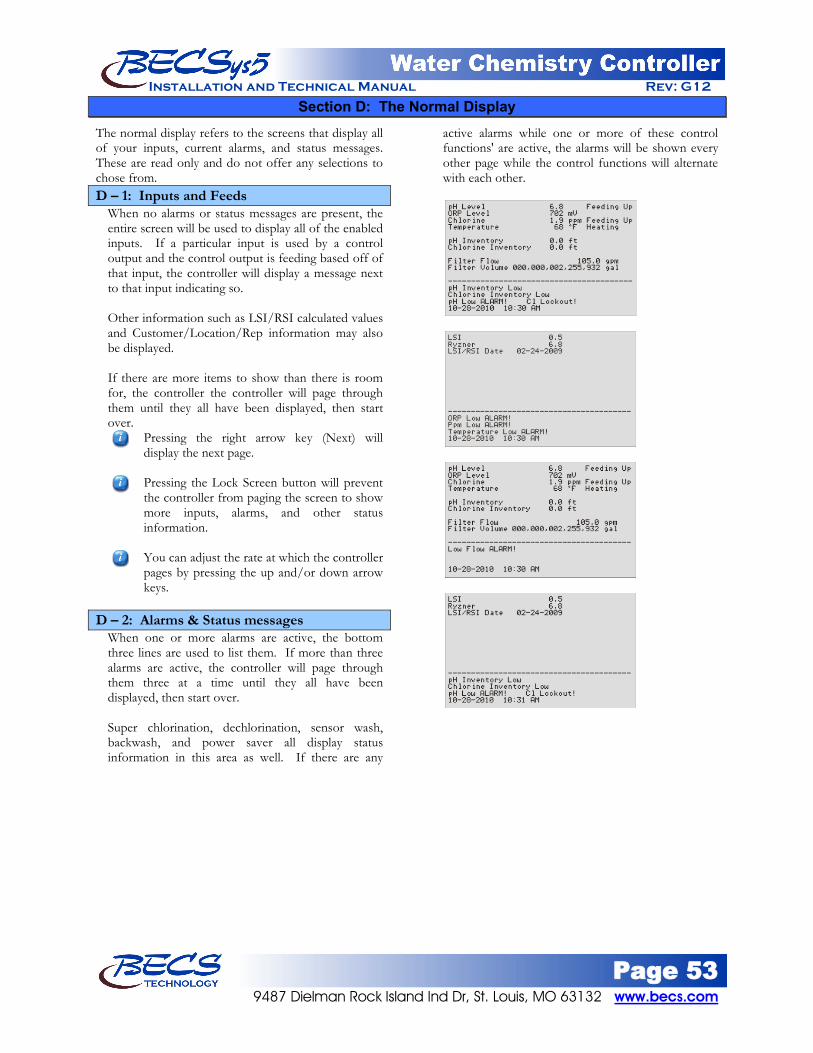
Page 53 9487 Dielman Rock Island Ind Dr, St. Louis, MO 63132 www.becs.com
Installation and Technical Manual Rev: G12
Section D: The Normal Display The normal display refers to the screens that display all of your inputs, current alarms, and status messages. These are read only and do not offer any selections to chose from. D – 1: Inputs and Feeds
When no alarms or status messages are present, the entire screen will be used to display all of the enabled inputs. If a particular input is used by a control output and the control output is feeding based off of that input, the controller will display a message next to that input indicating so. Other information such as LSI/RSI calculated values and Customer/Location/Rep information may also be displayed. If there are more items to show than there is room for, the controller the controller will page through them until they all have been displayed, then start over.
Pressing the right arrow key (Next) will display the next page. Pressing the Lock Screen button will prevent the controller from paging the screen to show more inputs, alarms, and other status information. You can adjust the rate at which the controller pages by pressing the up and/or down arrow keys.
D – 2: Alarms & Status messages
When one or more alarms are active, the bottom three lines are used to list them. If more than three alarms are active, the controller will page through them three at a time until they all have been displayed, then start over. Super chlorination, dechlorination, sensor wash, backwash, and power saver all display status information in this area as well. If there are any
active alarms while one or more of these control functions' are active, the alarms will be shown every other page while the control functions will alternate with each other.

Page 54 www.becs.com 9487 Dielman Rock Island Ind Dr, St. Louis, MO 63132
Installation and Technical Manual Rev: G12
Section E: Using the Face Panel Quick Keys
E – 1: The Set Points Key The Set Points Key on the front face panel, when pressed, allows you to quickly change desired feed set points for the various control outputs that are enabled.
To change the existing feed set point, first select the desired option, input the new value, and then press enter. Pressing the Set Points key a second time will display the alarm set points for all of the enabled inputs.
To change the existing alarm set point, first select the desired option, input the new value, and then press enter.
E – 2: The Relay Mode Key
Pressing the Relay Mode key on the front face panel shows you which options have been assigned relays, and each of the relays' current mode (AUTO/MANUAL OFF/MANUAL ON) and its state (Off or On). Pressing the Relay Mode key again will cycle through the Relay Modules connected to the controller, showing what is assigned to those relays and their current state.
By selecting one of the assigned relays, you are allowed to choose between automatic, manual on or manual off. Unused relays and the alarm relay cannot be manually overridden, but their current state is always displayed. If Manual On is selected, you will be prompted to enter how long the relay can stay in Manual On before returning to Auto (the maximum on time is 30 minutes).
To test a relay or to prime a pump (on the local relay screen), lock the screen while in the main Relay Mode menu, then press the relay's numeric key (i.e., for relay 3, press the 3 key). This will turn the relay on for as long as you are pressing that key. If the relay is already on, this will have no affect. The Relay Expansion modules have a button to test the relays.
If you have the controller set up to control a VFD, pressing the Relay Mode Key again will display the 4-20mA Control Outputs.
From here you can switch between auto and manual on. There are two different manual on options: Manual % Out and Manual Flow Rate. Manual % Out sets the VFD output at a specified
value. Manual Flow Rate changes the VFD output to maintain a specified flow rate.

Page 55 9487 Dielman Rock Island Ind Dr, St. Louis, MO 63132 www.becs.com
Installation and Technical Manual Rev: G12
E – 3: The Cal Key (calibration) Pressing the Cal (calibration) key on the front face panel will list the inputs you can perform a single point calibration on. Select the input you wish to calibrate and enter the proper value.
ORP can only be calibrated by Rep if the rep access code is set. Perform a single point calibration if the reading is off by a consistent amount throughout the input range. If the readings are accurate at one reading, but are off by an increasing amount the farther away you go from that reading, check the wiring and the condition of the probe (if applicable). If the problem is not found, you may need to do a two-point calibration located in the input's menu under the Menu button.
E – 4: The Reset Fail / Safe Key
The Reset Fail / Safe key on the front face panel, when pressed, provides the following information and options: Lists any active failsafe alarms and provides the
option to reset them. A failsafe alarm is generally triggered when one of the relays has remained on past the set time the function has been given to reach its set point. By choosing to reset the failsafe, the control that triggered the failsafe will be able to resume operating normally once again.
Displays the remaining time a relay may remain on before a failsafe will occur for each active feed with a failsafe time set.
Provides the option to abort the Flow Restored Feed Delay whenever the flow restored feed delay is enabled and is currently delaying feeds.
E – 5: The Emergency Off Key When the Emergency Off button is pressed, all relays are automatically shut off except for the alarm relay which will turn on. All the other relays will remain off until the emergency off button is press again.
Warning: Before resetting any failsafe alarms, ensure that all functions of the
controller are working properly.

Page 56 www.becs.com 9487 Dielman Rock Island Ind Dr, St. Louis, MO 63132
Installation and Technical Manual Rev: G12
Section F: Startup Programming
• This section covers programming the controller to enable specific features that people frequently need help doing so.
• All startup programming procedures require the user to be logged as Rep and do not include the step of logging on if the Rep access code has been set. If the Rep access code has not been set, the user is automatically logged on as Rep when they press any menu button.
F – 1: VFD Control
• The BECSys controller can control one or multiple VFD units based on the flow rate input. • To enable VFD control, you must assign one relay to the recirculation pump control and a 4-20mA output
channel. • The relay is wired to the VFD’s start/stop terminals. On most VFDs this signal is DC. You must use a
mechanical relay wired as a dry contact for DC signals. If no dry contact mechanical relays are available in the controller, you will need to instead use an external mechanical relay driven by any of the controller’s relays.
• When controlling more than one VFD, each VFD requires a separate relay and a separate 4-20mA output channel. Normally a single relay in the controller is used to activate all of the external relays wired to the VFDs’ start/stop inputs.
A) Assign a recirculation pump relay
1) Control Outputs Assign RelaysOther FeedsRecirculation Pump a. Select a relay from the list.
B) Assign a 4-20mA Output channel
1) 4-20mA Outs a. Select a channel to use for VFD Control
i. Set Usage to b. If controlling more than one VFD, repeat step a. for each VFD, assigning a different channel for
each.
VFD Control Out
C) Enable Flow Rate Input
1) Control InputsFlow RateEnable Input a. Set Enable Input to b. Select the scale to display the flow rate. If the flow rate will exceed 3276 gpm (or lpm), you should
select
Enable
0-327.67 kgpmD) Set the flow meter’s K factor
(or klpm).
1) Control InputsFlow Rate K Factor a. Enter the appropriate K Factor.
E) Configure VFD control and perform Auto Tune Previous versions of firmware required manually setting the VFD output prior to triggering auto tune.
This step is no longer needed.
1) Control OutputsRecirculation PumpVFD Control a. Set Control Input to b. Select
Flow Rate Auto Tune
i. . The controller will then query for the following information:
Max Flow Rateii.
: Enter pump’s rated output at 100%. Set Point
iii.
: Enter the flow rate you will normally operate your recirculation system at. Auto Tune will calibrate the system near this flow rate for optimal control. Trigger Auto Tune: Select Trigger
to begin the auto tune sequence.
Once auto tune is finished, the controller will begin controlling the VFD to maintain the programmed flow rate set point.

Page 57 9487 Dielman Rock Island Ind Dr, St. Louis, MO 63132 www.becs.com
Installation and Technical Manual Rev: G12
F – 2: Autofill • Autofill can be controlled using the Surge Pit 4-20mA level input or single point sensors like proximity sensors,
floats or the BECSys Solid State Autofill sensors. • When using single point sensors, you have the option to use one sensor to control both the start and stop fill,
or two sensors, one that senses the high (stop) level and another to sense the low (start) level. F – 2.1: 4-20mA level sensor (Surge Pit)
A) Enable Input
1) Control InputsSurge Pit a. Set Sensor Type to b. For
4-20mA Input Input Range
B) Assign a relay to Autofill , enter the length of the sensor installed.
1) Control OutputsAssign RelaysOther FeedsAutofill a. Select a relay from the list to control the autofill valve.
C) Configure Autofill
1) Control OutputsAutofill a. Set Control Input to b. Set the
Surge Pit
c. Configure the Set Point
Start delay and
End delay
F – 2.2: Single BECSys Solid State Sensor A) Reassign Input
1) Control InputsReassign Inputs 2) Select an input you will not be using for anything else from the list. 3) Assign that input’s function to be
B) Assign a relay to Autofill Autofill 1
1) Control OutputsAssign RelaysOther FeedsAutofill a. Select a relay from the list to control the autofill valve.
C) Configure Autofill
1) Control OutputsAutofill a. Set Control Input to b. Configure the
N.C. prox switch Start delay and
End delay
F – 2.3: Dual BECSys Solid State Sensors A) Reassign Inputs
1) Control InputsReassign Inputs a. Select an input you will not be using for anything else from the list.
i. Assign that input’s function to be b. Select a second input you will not be using for anything else from the list.
Autofill 1
i. Assign that input’s function to be B) Assign a relay to Autofill
Autofill 2
1) Control OutputsAssign RelaysOther FeedsAutofill 2) Select a relay from the list to control the autofill valve.
C) Configure Autofill
1) Control OutputsAutofill a. Set Control Input to b. Configure the
N.C. prox switch Start delay and
End delay
Page 58 www.becs.com 9487 Dielman Rock Island Ind Dr, St. Louis, MO 63132
Installation and Technical Manual Rev: G12
Section G: Troubleshooting
G – 1: Calibration Errors If during calibration of the inputs you receive an error message, check the following: G – 2.1: Specific Errors 1) "Points too close together or invalid." – Either
the values you entered or the input readings taken for those values were too close together to perform an accurate calibration calculation. Try calibrating again with a greater difference between the two points.
2) “Value too low. Check probe and flow.” – Indicated on free Cl calibrations if the user attempts to calibrate below 1.0 ppm for CCS140 sensors or 0.5 ppm for ECL6 sensors. Increase the chlorine in the pool above the values listed.
3) “Sensor error. Reading out of range.” – This message indicates the sensor would have been calibrated too far away from the controller’s safety limits. For ORP and pH sensors, this may indicate it is time to change the probes.
G – 2.2: General tips 1) Try calibrating again, allowing more time
between the 1st and 2nd point calibration. 2) If you are using a BECSys HRC-1 make sure the
Hi-Z switch is in the off position. 3) Double check to make sure you have the proper
wires connected to the input.
G – 2: Low Battery Alarm
The Low Battery Alarm is displayed when the controller detects the battery voltage is too low. If your controller is displaying a Low Battery Alarm, first double check the battery switch. Dip switch 8 on the CPU board is for the battery, it should be in the “On” position. If this switch is in the “On” position and the alarm is still displayed, you may have a dead battery.
G – 3: Chlorine Sensors G – 3.1: General Tips 1) Bouncing Readings – Verify that both flow and
pressure are constant. 2) No Flow Through Flow Cell – Verify the
position of the Total Chlorine Sensor. If the sensor is installed too far into the flow cell, it will restrict flow.
G – 3.2: Free Chlorine 1) Incorrect Reading – Try resetting the calibration.
(See Section C – 4.3.1.2). 2) Calibration Error – The calibration value must
be above 0.5 ppm.
G – 3.3: Total Chlorine 1) No Reading – If there is no electrolyte in the
Total Chlorine Sensor, the sensor will read 0. 2) No Reading – Possibly one of the fuses on the
Loop Power Supply Board has blown. Power down the controller and check the fuses using a multi-meter.
Page 59 9487 Dielman Rock Island Ind Dr, St. Louis, MO 63132 www.becs.com
Installation and Technical Manual Rev: G12
Section H: Maintenance The BECSys controller requires no maintenance other than a periodic calibration check and sensor cleaning. H – 1: Potentiometric Sensors (pH and ORP)
H – 1.1: Electrode Cleaning Slow response time and large offsets may indicate the electrode has become coated. The nature of the coating will dictate the type of cleaning technique that should be used. Soft coatings, like bacterial films, are best removed
using a squirt bottle or the water jet from a faucet. If this is not successful, then gently wipe with a soft wet cloth.
For a more severe coating, first try a strong detergent (something similar to Dawn liquid detergent) and warm water, using a soft brush (like a toothbrush). Isopropyl alcohol on a Q-tip is another good choice. Rinse the measuring end in distilled water before reinstallation.
Greasy and oily coatings are best removed with a detergent solution or a solvent that will not attack the sensor body. Methanol and isopropyl alcohol are good choices for solvents. Acetone, MEK, THF, or trichloroethane will irreparably harm the electrode.
Hard coatings, like calcium or lime scale, are best removed with a solvent appropriate for the particular coating. A 5% solution of hydrochloric acid (HCl) would be a good choice for calcium scale. If unsure of the proper solvent to remove a hard mineral coating, then alternate between a 5% hydrochloric acid and a 4% sodium hydroxide (NaOH) for 10 minutes each. After treating the electrode with these strong acids or bases, rinse the electrode with water and soak it in a pH 4 buffer for at least 1/2 hour.
The platinum tip of an ORP sensor can be cleaned with an abrasive as a last resort. Gently scour the platinum with a 600 grit wet emery cloth, or preferably, a 1-3 micron alumina polishing powder.
H – 1.2: Long-Term Storage
Save the wetting cap that came with the sensor for long-term storage. After removing the sensor from the flow cell, clean it as in routine maintenance, then store it in the wetting cap using
a pH 4 buffer saturated with potassium chloride (KCl). The potassium chloride will prevent electrolyte from leaching out of the sensors reference cell. The wetting cap only needs to be half full. If a number of sites are going to be serviced, for example, at the end of a season, then it might be a good idea to carry a pint of 4.0/KCl storage solution.
H – 2: Free Chlorine Sensor
Check the sensor measurement at regular intervals (at least once a month), and perform a recalibration if necessary. As a rule of thumb, refill the measuring cell with electrolyte once per season (or every 12 months). H – 2.1: Cleaning If the sensor membrane is visibly soiled, then
remove the sensor from the flow cell and clean the membrane with a gentle water jet, or soak the membrane for a few minutes in a 1% to 10% hydrochloric acid (HCl) solution. Avoid chemical additives as they may damage the membrane.
Replace a heavily soiled or damaged membrane. H – 2.2: Long-Term Storage
Save the yellow protective cap that came with the sensor for long-term storage. After removing the sensor from the flow cell, empty the measuring cell of electrolyte (particularly if dehydration of the membrane is possible). Rinse the measuring chamber and electrode shaft with cold water and let them dry. Then screw the measuring cell down loosely and not to the stop, so that the membrane remains unstressed. When the sensor is put back into service, it will have to be refilled with electrolyte and run through an initial polarization before calibration.
H – 2.3: Filling electrolyte Unscrew the measuring chamber from the shaft. Hold the measuring chamber at an angle and fill in
approximately 7 to 8 ml electrolyte, up to approximately 1 cm under the top edge.
Tap the filled chamber several times on a flat surface to release any air bubbles.
Screw the electrode shaft into the measuring chamber vertically from above, displacing all air from inside. Tighten slowly to the stop.
Warning: You may lightly blot the water on a pH sensor tip on a paper towel, but never
vigorously rub or wipe the pH bulb because this may scratch the delicate outer layer on the pH
glass impairing its response.

Page 60 www.becs.com 9487 Dielman Rock Island Ind Dr, St. Louis, MO 63132
Installation and Technical Manual Rev: G12
H – 3: Total Chlorine Sensor Check the sensor measurement at regular intervals (at least once a month), and perform a recalibration if necessary. As a rule of thumb, refill the measuring cell with electrolyte every 3 to 6 months. The membrane should be replaced once a year. H – 3.1: Long Term Storage
After removing the sensor from the flow cell, empty the measuring cell of electrolyte (particularly if dehydration of the membrane is possible). Rinse the measuring chamber and electrode shaft with cold water and let them dry. Then loosely screw the measuring cell down. The membrane must not rest against the measuring electrode. When the sensor is put back into service, the electrode tip must be cleaned with the special abrasive paper and a new membrane cap must be used.
H – 3.2: Cleaning The Electrode Tip To clean the electrode tip, first remove the membrane cap. Be sure to expose the vent when removing the membrane cap to prevent damage to the membrane. Clean the electrode finger using a clean, dry paper towel. The special abrasive paper is used on just the electrode tip. Place the special abrasive paper on a paper towel and hold it at one corner. Hold the probe perpendicular to the paper towel and abrasive paper and rub the electrode tip two or three times across the abrasive paper. Once the tip has been cleaned, replace the electrolyte.
H – 3.3: Filling Electrolyte See Section A – 6.3.
H – 4: Conductivity Sensor H – 4.1: Cleaning The sensor should be kept as clean as possible for
optimum measurement accuracy. The frequency of cleaning will depend upon the application.
When necessary, wash with strong detergent (something similar to Dawn liquid detergent) and warm water, using a pipe cleaner or small soft brush for most fouling. Rinse with tap water to completely remove the detergent, and then perform a final rinse with distilled or de-ionized water.
For hard scale, try a mild acid solution. Vinegar will often do it, 5% hydrochloric acid if the vinegar doesn’t work. You can use acetone or something similar on this sensor.
Warning: Do not soak the sensor in a strong solvent as the O-rings may be attacked after
time.
Warning: Residue from cleaning solutions, or even skin contact, can leave trace elements on
the sensor that may affect the reading,
Warning: Never touch the electrode finger.

Page 61 9487 Dielman Rock Island Ind Dr, St. Louis, MO 63132 www.becs.com
Installation and Technical Manual Rev: G12
Section I: Tables
I – 1: Flow Meter K-Factors
I – 1.1 Schedule 40 PVC Pipe Pipe
Size (in)
+GF+Signet 515 (red)
+GF+Signet 2536 (blue)
+GF+Signet 2551 Magmeter
U.S. GAL LITERS U.S.
GAL LITERS U.S. GAL LITERS
SCH 80 PVC SADDLE ON SCH 40 PVC PIPE
2 27.350 7.226 54.700 14.452 180.010 47.560 2-1/2 18.874 4.987 37.159 9.818 123.720 32.690 3 12.638 3.339 23.697 6.261 75.810 20.030 4 6.728 1.778 13.456 3.555 41.870 11.060 6 3.730 0.985 7.459 1.971 19.710 5.210 8 2.153 0.569 4.529 1.197 11.730 3.100 10 1.350 0.357 2.800 0.740 7.430 1.960 12 0.960 0.254 1.980 0.523 5.230 1.380
PP CLAMP-ON SADDLE ON SCH 40 PP PIPE
10 1.350 0.357 2.800 0.740 7.430 1.960
12 0.960 0.254 1.980 0.523 5.230 1.380
SCH 80 IRON SADDLE ON SCH 40 PIPE
2 26.820 7.086 53.640 14.172 185.350 48.970 2-1/2 18.800 4.967 37.600 9.934 127.470 33.680 3 11.990 3.168 23.220 6.135 76.620 20.240 4 6.850 1.810 13.260 3.503 40.230 10.630 5 5.330 1.408 11.040 2.917 27.320 7.220 6 3.760 0.993 7.240 1.913 19.710 5.210 8 2.130 0.563 4.400 1.162 11.610 3.070 10 1.350 0.357 2.800 0.740 7.360 1.940 12 0.960 0.254 1.980 0.523 5.180 1.370
CARBON STEEL WELDOLETS ON SCH 40 PIPE
2-1/2 18.800 4.967 37.600 9.934 105.700 27.930 3 12.170 3.215 24.340 6.431 70.680 18.670 4 6.960 1.839 13.920 3.678 36.380 9.610 5 5.260 1.390 10.860 2.869 29.280 7.730 6 3.690 0.975 7.520 1.987 20.290 5.360 8 2.130 0.563 4.340 1.147 11.730 3.100 10 1.350 0.357 2.760 0.729 7.450 1.970 12 0.960 0.254 1.940 0.513 5.240 1.390
STAINLESS STEEL WELDOLETS ON SCH 40 PIPE
2-1/2 18.800 4.967 37.600 9.934 106.310 28.090 3 12.170 3.215 24.340 6.431 72.270 19.090 4 6.960 1.839 13.920 3.678 36.840 9.730 5 5.260 1.390 10.860 2.869 29.280 7.730 6 3.690 0.975 7.520 1.987 20.290 5.360 8 2.130 0.563 4.340 1.147 11.730 3.100 10 1.350 0.357 2.760 0.729 7.450 1.970 12 0.960 0.254 1.940 0.513 5.240 1.390
I – 1.2 Schedule 80 PVC Pipe
Pipe Size (in)
+GF+Signet 515 (red)
+GF+Signet 2536 (blue)
+GF+Signet 2551 Magmeter
U.S. GAL LITERS U.S.
GAL LITERS U.S. GAL LITERS
SCH 80 PVC TEES FOR SCH 80 PVC PIPE
1 174.670 46.148 352.440 93.114 n/a 231.670 1-1/4 83.390 22.032 177.180 46.812 n/a 118.110 1-1/2 58.580 15.477 117.850 31.137 324.190 85.650 2 32.480 8.581 66.739 17.633 206.690 54.610 2-1/2 21.833 5.768 42.994 11.359 131.460 34.730 3 13.541 3.578 26.652 7.041 82.520 21.800 4 7.626 2.015 15.006 3.965 44.780 11.830
SCH 80 PVC SADDLES FOR SCH 80 PVC PIPE
2 32.480 8.581 66.739 17.633 193.830 51.210 2-1/2 21.833 5.768 42.994 11.359 138.010 36.460 3 13.541 3.578 26.652 7.041 83.890 22.160 4 7.626 2.015 15.006 3.965 40.880 10.800 6 4.162 1.100 8.325 2.199 22.530 5.950 8 2.371 0.626 5.016 1.325 12.520 3.310 10 1.530 0.404 3.060 0.808 7.940 2.100 12 1.060 0.280 2.160 0.571 5.710 1.510
PP CLAMP-ON SADDLE ON SCH 80 PP PIPE
10 1.530 0.404 3.060 0.808 7.940 2.100
12 1.060 0.280 2.160 0.571 5.710 1.510
SCH 80 IRON SADDLES ON SCH 80 PIPE
2 32.360 8.550 64.720 17.099 194.850 51.480 2-1/2 22.220 5.871 42.480 11.223 142.280 37.590 3 13.420 3.546 26.420 6.980 87.530 23.130 4 7.660 2.024 14.700 3.884 40.620 10.730 5 5.860 1.548 12.180 3.218 29.280 7.740 6 4.090 1.081 8.440 2.230 22.300 5.890 8 2.330 0.616 4.900 1.295 12.520 3.310 10 1.530 0.404 3.060 0.808 7.940 2.100 12 1.060 0.280 2.160 0.571 5.650 1.490

Page 62 www.becs.com 9487 Dielman Rock Island Ind Dr, St. Louis, MO 63132
Installation and Technical Manual Rev: G12
Section J: Feed Charts Use the charts on the following pages to determine the correct amount of chemical to add to spa or pool water to achieve desired conditions. Choose which chart to use by the chemical indicated and the number of gallons to be treated. J – 1: Spa Feed Charts
Quantity of Muriatic Acid Needed to Lower Total Alkalinity
Desired Decrease In ppm
Gallons in Spa
100 150 250 500 750 1000 10 1.25 ts 2.00 ts 1.00 tb 2.00 tb 3.00 tp 0.25 cp 20 2.50 ts 4.00 ts 2.00 tb 0.25 cp 0.33 cp 0.50 cp 30 1.25 tb 2.00 tb 3.00 tb 0.33 cp 0.67 cp 0.75 cp 40 5.00 ts 2.50 tb 0.25 cp 0.50 cp 0.75 cp 1.00 cp 50 2.00 tb 3.00 tb 5.00 tb 0.67 cp 1.00 cp 1.33 cp 60 2.50 tb 0.25 cp 0.33 cp 0.75 cp 1.00 cp 1.50 cp 70 3.00 tb 0.25 cp 0.50 cp 1.00 cp 1.33 cp 1.75 cp 80 3.50 tb 0.33 cp 0.50 cp 1.00 cp 1.50 cp 2.00 cp 90 0.25 cp 0.33 cp 0.67 cp 1.00 cp 1.67 cp 2.33 cp 100 0.25 cp 0.50 cp 0.67 cp 1.33 cp 2.00 cp 2.50 cp
ts = teaspoon tb = tablespoon cp = one cup (8 fl oz)
Quantity of Sodium Bisulfate Needed to Lower Total Alkalinity
Desired Decrease In ppm
Gallons in Spa
100 150 250 500 750 1000 10 1.50 ts 2.50 ts 1.00 tb 2.50 tb 0.25 cp 0.33 cp 20 1.00 tb 1.50 tb 2.50 tb 0.33 cp 0.50 cp 0.67 cp 30 1.50 tb 2.50 tb 0.25 cp 0.50 cp 0.75 cp 1.00 cp 40 2.00 tb 3.00 tb 0.33 cp 0.67 cp 1.00 cp 1.25 cp 50 2.50 tb 0.25 cp 0.50 cp 0.75 cp 1.25 cp 1.50 cp 60 3.00 tb 4.50 tb 0.50 cp 1.00 cp 1.50 cp 2.00 cp 70 0.25 cp 0.33 cp 0.50 cp 1.00 cp 1.67 cp 2.25 cp 80 0.25 cp 0.33 cp 0.67 cp 1.25 cp 2.00 cp 2.50 cp 90 0.33 cp 0.50 cp 0.75 cp 1.50 cp 2.25 cp 3.00 cp 100 0.33 cp 0.50 cp 0.75 cp 1.67 cp 2.50 cp 3.25 cp
ts = teaspoon tb = tablespoon cp = one cup (8 fl oz)
Quantity of Bicarbonate of Soda Needed to Raise Total Alkalinity
Desired Increase In ppm
Gallons in Spa
100 150 250 500 750 1000 10 1.25 ts 2.00 ts 4.00 ts 2.50 tb 0.25 cp 0.33 cp 20 1.00 tb 1.50 tb 2.50 tb 5.00 tb 0.50 cp 0.50 cp 30 1.50 tb 2.00 tb 3.50 tb 0.50 cp 0.67 cp 1.00 cp 40 2.00 tb 3.00 tb 0.33 cp 0.50 cp 1.00 cp 1.00 cp 50 2.50 tb 3.50 tb 6.00 tb 0.75 cp 1.00 cp 1.50 cp 60 3.00 tb 0.25 tb 0.50 cp 1.00 cp 1.33 cp 1.75 cp 70 3.50 tp 0.35 cp 0.50 cp 1.00 cp 1.50 cp 2.00 cp 80 0.25 cp 0.33 cp 0.50 cp 1.25 cp 1.75 cp 2.50 cp 90 0.33 cp 0.50 cp 0.67 cp 1.33 cp 2.05 cp 2.75 cp 100 0.33 cp 0.50 cp 0.75 cp 1.50 cp 2.25 cp 3.00 cp
ts = teaspoon tb = tablespoon cp = one cup (8 fl oz)
Quantity of Calcium Chloride Needed to Increase Calcium Hardness
Desired Increase In ppm
Gallons in Spa
100 150 250 500 750 1000 10 1.25 ts 2.00 ts 1.00 tb 2.00 tb 3.00 tb 0.25 cp 20 2.50 ts 4.00 ts 2.00 tb 0.25 cp 0.33 cp 0.50 cp 30 1.25 tb 2.00 tb 3.00 tb 0.33 cp 0.67 cp 0.75 cp 40 4.00 ts 2.50 tb 0.25 cp 0.50 cp 0.75 cp 1.00 cp 50 2.00 tb 3.00 tb 5.00 tb 0.67 cp 1.00 cp 1.33 cp 60 2.50 tb 0.25 cp 0.33 cp 0.75 cp 1.00 cp 1.50 cp 70 3.00 tp 0.25 cp 0.50 cp 1.00 cp 1.33 cp 1.75 cp 80 3.50 tp 0.25 cp 0.50 cp 1.00 cp 1.50 cp 2.00 cp 90 0.25 cp 0.33 cp 0.33 cp 1.00 cp 1.67 cp 2.33 cp 100 0.25 cp 0.50 cp 0.67 cp 1.33 cp 2.00 cp 2.50 cp
ts = teaspoon tb = tablespoon cp = one cup (8 fl oz)
Quantity of Chlorine Compound Needed to Increase 1 ppm
Percent Chlorine In
Product
Gallons in Spa
100 150 250 500 750 1000 5 0.50 tb 2.00 ts 1.25 tb 2.50 tb 0.25 cp 0.33 cp 10 0.25 tb 1.00 ts 2.00 ts 1.25 tb 2.00 tb 2.50 tb 12 0.25 tb 1.00 ts 0.50 tb 1.00 tb 1.50 tb 2.00 tb 30 0.25 tb 0.33 ts 0.75 ts 1.25 ts 2.00 ts 2.50 ts 40 0.167 ts 0.25 ts 0.500 ts 1.00 ts 1.50 ts 2.00 ts 50 0.167 ts 0.25 ts 0.375 ts 0.75 ts 1.25 ts 1.50 ts 60 0.167 tb 0.200 ts 0.375 ts 0.50 ts 1.00 ts 1.25 ts 65 0.100 ts 0.167 ts 0.250 ts 0.50 ts 0.75 ts 1.00 ts
ts = teaspoon tb = tablespoon cp = one cup (8 fl oz)

Page 63 9487 Dielman Rock Island Ind Dr, St. Louis, MO 63132 www.becs.com
Installation and Technical Manual Rev: G12
J – 2: Pool Feed Charts
Quantity of Muriatic Acid Needed to Lower Total Alkalinity Desired Decrease
In ppm Gallons in Pool
10,000 25,000 50,000 75,000 100,000 200,000 500,000 750,000 1,000,000 10 1.30 pt 1.62 qt 3.25 qt 1.22 gl 1.62 gl 3.25 gl 8.13 gl 12.20 gl 16.25 gl 20 1.30 pt 3.25 qt 1.62 gl 2.43 gl 3.25 gl 7.50 gl 16.20 gl 24.30 gl 32.50 gl 30 1.95 qt 1.22 gl 2.44 gl 3.86 gl 4.98 gl 9.76 gl 24.40 gl 36.60 gl 48.80 gl 40 2.80 qt 1.63 gl 3.25 gl 4.87 gl 6.50 gl 13.00 gl 32.50 gl 48.80 gl 65.00 gl 50 3.25 qt 2.03 gl 4.07 gl 6.10 gl 8.14 gl 16.28 gl 40.70 gl 61.00 gl 81.40 gl 60 3.90 qt 2.44 gl 4.88 gl 7.32 gl 9.76 gl 19.52 gl 48.80 gl 73.20 gl 97.80 gl 70 1.14 gl 2.84 gl 5.69 gl 8.54 gl 11.38 gl 22.76 gl 56.90 gl 85.45 gl 113.80 gl 80 1.30 gl 3.25 gl 6.50 gl 9.75 gl 13.00 gl 26.00 gl 65.00 gl 97.50 gl 138.00 gl 90 1.48 gl 3.66 gl 7.31 gl 10.96 gl 14.82 gl 29.24 gl 73.10 gl 109.60 gl 146.20 gl 100 1.63 gl 4.06 gl 8.12 gl 12.18 gl 16.24 gl 32.48 gl 81.20 gl 121.80 gl 162.40 gl 120 1.96 gl 4.88 gl 9.76 gl 14.64 gl 19.52 gl 39.00 gl 97.80 gl 148.40 gl 196.20 gl 150 2.44 gl 6.09 gl 12.18 gl 18.27 gl 24.40 gl 48.80 gl 121.80 gl 182.70 gl 244.00 gl 200 3.25 gl 8.12 gl 18.24 gl 24.36 gl 32.50 gl 65.00 gl 162.40 gl 243.80 gl 325.00 gl
pt = one pt (16 fl oz) qt = one quart (32 fl oz) gl = one gallon (128 fl oz)
Quantity of Bicarbonate of Soda Needed to Raise Total Alkalinity Desired Increase
In ppm Gallons in Pool
10,000 25,000 50,000 75,000 100,000 200,000 500,000 750,000 1,000,000 10 1.50 lb 3.75 lb 7.50 lb 11.25 lb 15.00 lb 30.00 lb 75.00 lb 112.50 lb 150.00 lb 20 3.00 lb 7.50 lb 15.00 lb 22.50 lb 30.00 lb 60.00 lb 150.00 lb 225.00 lb 300.00 lb 30 4.50 lb 11.25 lb 22.50 lb 33.75 lb 45.00 lb 90.00 lb 225.00 lb 337.50 lb 450.00 lb 40 6.00 lb 15.00 lb 30.00 lb 45.00 lb 60.00 lb 120.00 lb 300.00 lb 450.00 lb 600.00 lb 50 7.50 lb 18.75 lb 37.50 lb 56.25 lb 75.00 lb 150.00 lb 375.00 lb 562.50 lb 750.00 lb 60 9.00 lb 22.50 lb 45.00 lb 67.50 lb 90.00 lb 180.00 lb 450.00 lb 675.00 lb 900.00 lb 70 10.50 lb 26.25 lb 52.50 lb 78.75 lb 105.00 lb 210.00 lb 525.00 lb 787.50 lb 1050.00 lb 80 12.00 lb 30.00 lb 60.00 lb 90.00 lb 120.00 lb 240.00 lb 600.00 lb 900.00 lb 1200.00 lb 90 13.50 lb 33.75 lb 67.50 lb 101.25 lb 135.00 lb 270.00 lb 675.00 lb 1012.50 lb 1350.00 lb 100 15.00 lb 37.50 lb 75.00 lb 112.50 lb 150.00 lb 300.00 lb 750.00 lb 1125.00 lb 1500.00 lb
lb =pounds of dry chemical
Quantity of Calcium Chloride Needed to Increase Calcium Hardness
Desired Increase In ppm
Gallons in Pool 10,000 25,000 50,000 75,000 100,000 200,000 500,000 750,000 1,000,000
lb oz lb oz lb oz lb oz lb oz lb lb oz lb oz lb 10 1 4 3 2 6 4 9 6 12 8 25 62 8 93 12 125 20 2 8 6 4 12 8 18 12 25 0 50 125 0 197 8 250 30 3 12 9 6 18 12 28 2 37 8 75 187 8 281 4 375 40 5 0 12 8 25 0 37 8 50 0 100 250 0 375 0 500 50 6 4 15 10 31 4 46 14 62 8 125 312 8 468 12 625 60 7 8 18 12 37 8 56 4 75 0 150 375 0 562 8 750 70 8 12 21 14 43 12 65 10 87 8 175 437 8 658 4 875 80 10 0 25 0 50 0 75 0 100 0 200 500 0 750 0 1,000 90 11 4 28 2 56 4 84 6 112 8 225 562 8 843 12 1,125 100 12 8 31 4 62 8 93 12 125 0 250 625 0 937 8 1,250 150 18 12 46 14 93 12 104 10 187 8 375 937 8 1,406 4 1,875 200 25 0 62 8 125 0 187 8 250 0 500 1,250 0 1,875 0 2,500
Quantity of Chlorine Compound Needed to Increase 1 ppm
Percent Chlorine In Product
Gallons in Pool 10,000 25,000 50,000 75,000 100,000 200,000 500,000 750,000 1,000,000
5 3.2 cp 2 qt 1 gl 1.5 gl 2 gl 4 gl 10 gl 15 gl 20 gl 10 1.6 cp 1 qt 2 qt 3 qt 1 gl 2 gl 5 gl 7.5 gl 10 gl 12 1.33 cp 1.67 pt 1.517 qt 2.276 pt 3.33 qt 1.665 gl 4.163 gl 6.245 gl 8.326 gl 30 0.278 lb 0.665 lb 1.390 lb 2.085 lb 2.780 lb 5.580 lb 13.900 lb 20.850 lb 27.800 lb 40 0.209 lb 0.521 lb 1.043 lb 1.565 lb 2.086 lb 4.172lb 10.430 lb 15.645 lb 20.860 lb 50 0.167 lb 0.417 lb 0.834 lb 1.251 lb 1.668 lb 3.336lb 8.340lb 12.511 lb 16.680 lb 60 0.139 lb 0.348 lb 0.695 lb 1.043 lb 1.390 lb 2.780lb 6.950 lb 10.425 lb 13.900 lb 65 0.128 lb 0.321 lb 0.642 lb 0.963 lb 1.284 lb 2.568lb 6.420 lb 9.630lb 12.840 lb 70 0.119 lb 0.298 lb 0.596 lb 0.894 lb 1.192 lb 2.384lb 5.960lb 8.940 lb 11.920 lb 75 0.111 lb 0.278 lb 0.556 lb 0.834 lb 1.112 lb 2.224 lb 5.560 lb 8.340 lb 11.120 lb 80 0.104 lb 0.261 lb 0.521 lb 0.782 lb 1.042 lb 2.064 lb 5.210 lb 7.815 lb 10.420 lb 85 0.096 lb 0.417 lb 0.491 lb 0.737 lb 0.982 lb 1.964 lb 4.910 lb 7.365 lb 9.829 lb 90 0.093 lb 0.232 lb 0.463 lb 0.695 lb 0.926 lb 1.852 lb 4.630 lb 6.945 lb 9.260 lb 100 0.083 lb 0.209 lb 0.417 lb 0.626 lb 0.634 lb 1..668 lb 4.170 lb 6.225lb 8.340 lb
cp = one cup (8 fl oz) pt = one pt (16 fl oz) qt = one quart (32 fl oz) gl = one gallon (128 fl oz) lb =pounds of dry chemical

Page 64 www.becs.com 9487 Dielman Rock Island Ind Dr, St. Louis, MO 63132
Installation and Technical Manual Rev: G12
Section K: Installation Diagrams
K – 1: Pressure Filter Installation
K – 2: Vacuum Filter Installation

Page 65 9487 Dielman Rock Island Ind Dr, St. Louis, MO 63132 www.becs.com
Installation and Technical Manual Rev: G12
Section L: Replacement Parts Fuses 8140086 115V Unit Main Fuse Time Lag 250mA 250V 8140093 230V Unit Main Fuse Time Lag 125mA 250V 8140088 Relays 1-4 Time Lag 3A 250V 8140059 RS485 Fuse Time Lag 250mA 250V 8140091 4-20mA Loop Power Board Time Lag 50mA 250V 8320053 Fuse Cap Sensors pH Sensors 9660013 BECSys pH Sensor (30” cable) [range: 0 to 14.0 pH] 9660010 BECSys pH Sensor (10’ cable) [ range: 0 to 14.0 pH] ORP Sensors 9660022 BECSys ORP Sensor Platinum Band (30” cable)
[range: 0 to 1000mV] 9660023 BECSys ORP Sensor Platinum Band (10’ cable)
[range: 0 to 1000mV] 9660038 BECSys ORP Sensor Solid Gold Band (30” cable)
[range: 0 to 1000mV] 9660040 BECSys ORP Sensor Solid Gold Band (10’ cable)
[range: 0 to 1000mV] pH/ORP Sensor Accessories 8500061 4/KCl solution (pint); for long-term storage of sensors 8680015 ½” Wetting Cap for pH and ORP sensors Temperature Sensors 9660016 Temperature Sensor (30” cable)
[range: 32°F to 212°F (0°C to 100°C)] 9660003 Temperature Sensor (10’ cable)
[range: 32°F to 212°F (0°C to 100°C)] Flow Switches 9660006 Reed flow switch [Switch Point (On): 2.0 gpm] 9660007 Rotary flow switch [Switch Point (On): 1.5 gpm] 9060547 Spring Check Valve 8680019 Rotary Flow Switch Replacement Kit includes: 1 Pin,
1 Cover, 1 Wheel, 1 O-ring 8060663 Rotary Flow Switch Replacement Pin 8060664 Rotary Flow Switch Replacement Cover 8060665 Rotary Flow Switch Replacement Wheel 8060666 Rotary Flow Switch Replacement O-Ring Amperometric ppm (Cl) 9660005 Amperometric Sensor only, no flow cell
[range: 0 to 20 ppm] 8680016 Replacement Membranes (2 pieces) for
Amperometric Chlorine Sensor 9660005 8680017 Electrolyte (50 ml) for Chlorine Sensor 9660005 2220363 Amperometric ppm Probe Nut Total Chlorine 8660044 Total Chlorine Sensor only, no flow cell
[range: 0 to 20 ppm] 2220359 Probe Ring 2220360 Total Chlorine Probe Nut 2220361 O-Ring Retainer 8060808 O-Ring 3/32x0.987 ID 8060809 O-Ring 3/32x1.174 ID Pressure and Vacuum 8660029 Pressure transducer only, no cable
[range: 0 to 100 PSI] 8660033 Vacuum transducer only, no cable
[range: -14.7 to 85 PSI] 9660019 Vacuum Swichgage [range: 0 to 30 in. HG] 9660020 Pressure Swichgage [range: 0 – 50 PSI] 8660021 Differential Swichgage [range: 0 – 50 PSI] Conductivity/TDS 9660012 BECSys Conductivity Sensor
[range: 0 to 20,000 micromho] Turbidimeter 1210261 BECSys Turbidimeter [range: 0 to 20.00 NTU] 9680024 Dessicant Tray – Refill Flowmeters 8660008 Flowmeter (1/2” to 4”) [range: 0 to 655.35 Kgpm] 9660009 Flowmeter (5” to 8”) [range: 0 to 655.35 Kgpm] 9660004 Flowmeter (10” to 36”) [range: 0 to 655.35 Kgpm]
Boards 1200409 BECSys5 CPU/Relay PCB 1200411 BECSys5 UI PCB Input Boards 1200413 BECSys5 Standard Input Board 1200506 BECSys5 Conductivity Input Board 1200531 Remote Probe Module Interface Board Communications Boards 1200459 BECSys 56k Data/Fax Modem PCB 1200491 BECSys Ethernet PCB 1200438 BECSys Ethernet + 56k Data Modem PCB 1200612 BECSys Modbus Ethernet PCB 1200613 BECSys Modbus Ethernet + 56k Data Modem PCB Other Boards 1200494 BECSys Loop Power Board (4 power supplies for 4-
20mA inputs) 1200453 BECSys 4-20mA output board (4 channel, 440 ohm)
with 4 power supplies for 4-20mA inputs Software 1230079 BECSys5 Program IC (DIP) 2230079 BECSys5 Program IC (PLCC) 1230089 BECSys for Windows CD and Manual (media only, no
license) 8680025 DIP Extraction Tool 8680026 DIP Insertion Tool 9680014 PLCC Extraction Tool Documentation 8620007 BECSys5 Operation and Maintenance Manual 8620013 BECSys5 Installation and Technical Manual 8620036 BECSys5 Quick Reference Sheet Misc Enclosure Parts 8060627 Enclosure Plug 0.875” 8060628 Enclosure Plug 1.125” 8520173 Single BNC cable assembly 8060734 Small watertight cord grip PG-7 8060735 Large watertight cord grip NPT ½” 9440137 BECSys5 Overlay M000069 BECSys5 Lid Assembly Internal Components 8060237 Stack Board Standoffs 8060452 Stack Board Screws 9060526 Shield Screws 8380650 RS485 IC 9520039 Ribbon Cable 8020003 Battery 8041102 2 Position Pluggable Terminal Block (Inputs) 8041103 3 Position Pluggable Terminal Block (RS485, Flow
Meter, Flow Switch) 8041104 5 Position Pluggable Terminal Block (Direct Connect) Communications Cables 9520136 BECSys DB9 6 ft Direct Connect Cable 9520196 BECSys DB9 50 ft Direct Connect Cable 9520197 BECSys USB 6 ft Direct Connect Cable 9520198 BECSys USB 50 ft Direct Connect Cable

Page 66 www.becs.com 9487 Dielman Rock Island Ind Dr, St. Louis, MO 63132
Installation and Technical Manual Rev: G12 Flow Cell Replacement Parts Round Flow Cell 1220210 Round Flow Cell Body 1220205 Acrylic Cover for Round Flow Cell 8060626 O-Ring for Round Flow Cell 1220207 PVC Mounting Plate for Round Flow Cell 8080625 Screws – Mounting Plate Rectangular Flow Cell 1220201 2-Sensor Rectangular Flow Cell Body 1220200 Acrylic Cover for 2-Sensor Rectangular Flow Cell 8060669 O-Ring for 2-Sensor Rectangular Flow Cell 1220288 3-Sensor Rectangular Flow Cell Body 1220287 Acrylic Cover for 3-Sensor Rectangular Flow Cell 8060695 O-Ring for 3-Sensor Rectangular Flow Cell Common Flow Cell Components 8060189 Screws – Acrylic Cover 8060623 Elbow, 90° PVC 8060624 Elbow, 45° PVC 8060538 Plug, ¼” PVC 8060541 Nipple, ½” Close 8060621 Sample Valve, ¼” Ball Cock 9060546 Ball Valve ½” PVC 9060549 S80 Bushing, PVC ¾ x ½ 9060544 Pressure Gauge 8060673 Pressure Regulator

Page 67 9487 Dielman Rock Island Ind Dr, St. Louis, MO 63132 www.becs.com
Installation and Technical Manual Rev: G12
Section M: Warranty
LIMITED WARRANTY BECS warrants the controller electronics and flow cell against any defect in workmanship or materials for a period of five years from the date of shipment. BECS warrants the pH and ORP sensors against any defect in workmanship or materials for a period of two years from the date of shipment. In the event of a component failure due to any defect in workmanship or materials, BECS will repair, or if repair is not possible, replace the defective part or parts of the BECSys controller. BECS will have the sole right to determine whether to repair or replace a product. BECS will not be responsible for any expense associated with installation of repaired or replacement parts. LIMITATIONS AND EXCLUSIONS This is a LIMITED WARRANTY. BECS makes NO WARRANTIES other than those contained herein. The LIMITED WARRANTY replaces and is in lieu of any WARRANTIES of MERCHANTABILITY or of FITNESS FOR A PARTICULAR PURPOSE which are expressly DISCLAIMED. All GENERAL, SPECIAL, INDIRECT, INCIDENTAL AND/OR CONSEQUENTIAL DAMAGES ARE EXCLUDED AND DISCLAIMED. This Limited Warranty is governed by Missouri Law and all disputes related to or arising from this transaction or Limited Warranty shall be resolved in Circuit Court of St. Louis County, Missouri. Any claims under this Limited Warranty must be brought within ONE YEAR after the cause of action accrued.

Document Part Number: 8620013-G12
July 2012 9487 Dielman Rock Island Ind Dr, St. Louis, MO 63132 www.becs.com
Installation and Technical Manual Rev: G12
has been designing and manufacturing the industry’s most
reliable water chemistry controller for over 20 years. Our 24,000 ft2 facility in Saint Louis, Missouri is home to an exceptional design team, and all manufacturing is performed onsite at this facility where we can personally assure the quality of our products. The BECS commitment to excellence drives the most innovative new products and unparalleled customer service.


![Soft Start-up Valve · 200 V 1.18 (With light: 1.22) 1.15 (With light: 1.30) 220 V [230 V] 1.30 (With light: 1.34) [1.42 (With light: 1.46)] 1.27 (With light: 1.46) [1.39 (With light:](https://static.fdocuments.in/doc/165x107/5edc9208ad6a402d666749e5/soft-start-up-valve-200-v-118-with-light-122-115-with-light-130-220-v.jpg)


![Untitled-1 []Sobha Developers 2.24 Pharmaceuticals 1.46 Dr. Reddy's Laboratories 1.46 Gas 1.15 Indraprastha Gas 1.15 Construction Project 0.97 Larsen & Toubro 0.97 Total Equity 93.80](https://static.fdocuments.in/doc/165x107/603230585b49e508524df68f/untitled-1-sobha-developers-224-pharmaceuticals-146-dr-reddys-laboratories.jpg)