Beams I -- Bending...
15
Bending Stresses in Beams Hide Text 1 OverView Hide Text 2 In this stack, our goal is to develop a means for determining the stresses in a beam. OverView Hide Text 3 We will proceed by first determining the strains due to bending… OverView Hide Text 4 …and then use Hooke's law to determine the stresses. Beams I -- Bending Stresses: 1
Transcript of Beams I -- Bending...
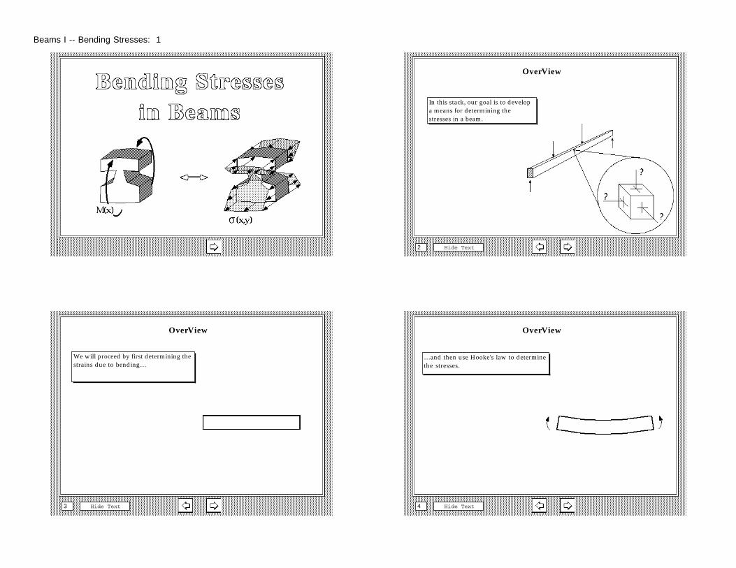
Bending Stresses in Beams
Hide Text1
OverView
Hide Text2
In this stack, our goal is to develop a means for determining the stresses in a beam.
OverView
Hide Text3
We will proceed by first determining the strains due to bending…
OverView
Hide Text4
…and then use Hooke's law to determine the stresses.
Beams I -- Bending Stresses: 1
Beam
Hide Text5
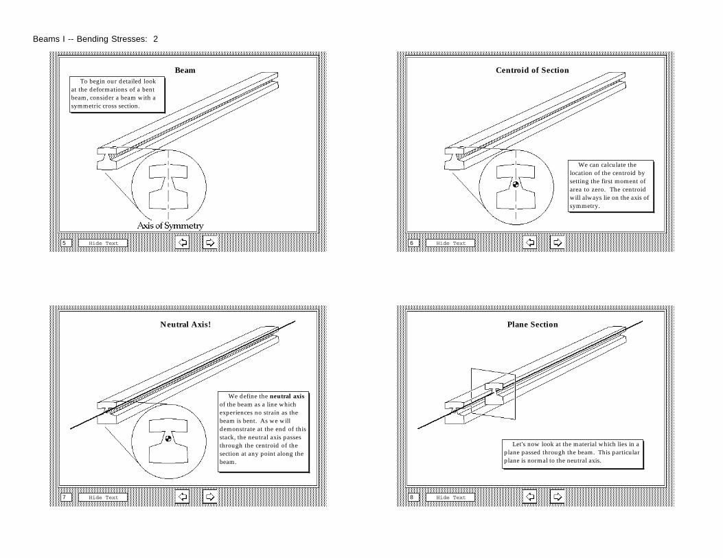
To begin our detailed look at the deformations of a bent beam, consider a beam with a symmetric cross section.
Centroid of Section
Hide Text6
We can calculate the location of the centroid by setting the first moment of area to zero. The centroid will always lie on the axis of symmetry.
Neutral Axis!
Hide Text7
We define the neutral axis of the beam as a line which experiences no strain as the beam is bent. As we will demonstrate at the end of this stack, the neutral axis passes through the centroid of the section at any point along the beam.
Plane Section
Hide Text8
Let's now look at the material which lies in a plane passed through the beam. This particular plane is normal to the neutral axis.
Beams I -- Bending Stresses: 2
Apply Load
Hide Text9
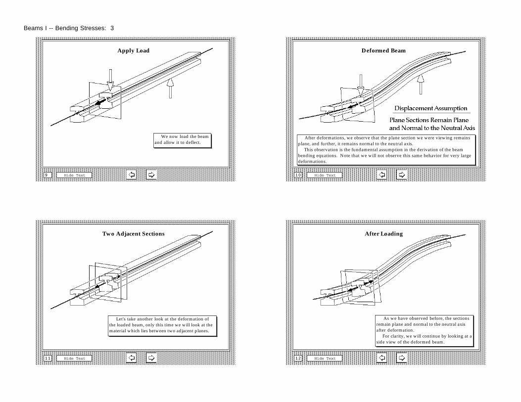
We now load the beam and allow it to deflect.
Deformed Beam
Hide Text1 0
After deformations, we observe that the plane section we were viewing remains plane, and further, it remains normal to the neutral axis. This observation is the fundamental assumption in the derivation of the beam bending equations. Note that we will not observe this same behavior for very large deformations.
Two Adjacent Sections
Hide Text1 1
Let's take another look at the deformation of the loaded beam, only this time we will look at the material which lies between two adjacent planes.
After Loading
Hide Text1 2
As we have observed before, the sections remain plane and normal to the neutral axis after deformation. For clarity, we will continue by looking at a side view of the deformed beam.
Beams I -- Bending Stresses: 3
Hide Text1 3
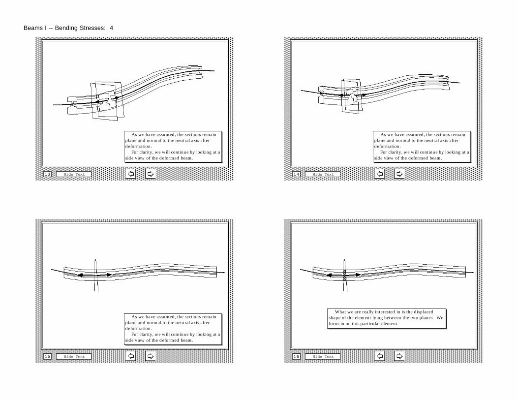
As we have assumed, the sections remain plane and normal to the neutral axis after deformation. For clarity, we will continue by looking at a side view of the deformed beam.
Hide Text1 4
As we have assumed, the sections remain plane and normal to the neutral axis after deformation. For clarity, we will continue by looking at a side view of the deformed beam.
Hide Text1 5
As we have assumed, the sections remain plane and normal to the neutral axis after deformation. For clarity, we will continue by looking at a side view of the deformed beam.
Hide Text1 6
What we are really interested in is the displaced shape of the element lying between the two planes. We focus in on this particular element.
Beams I -- Bending Stresses: 4
Hide Text1 7
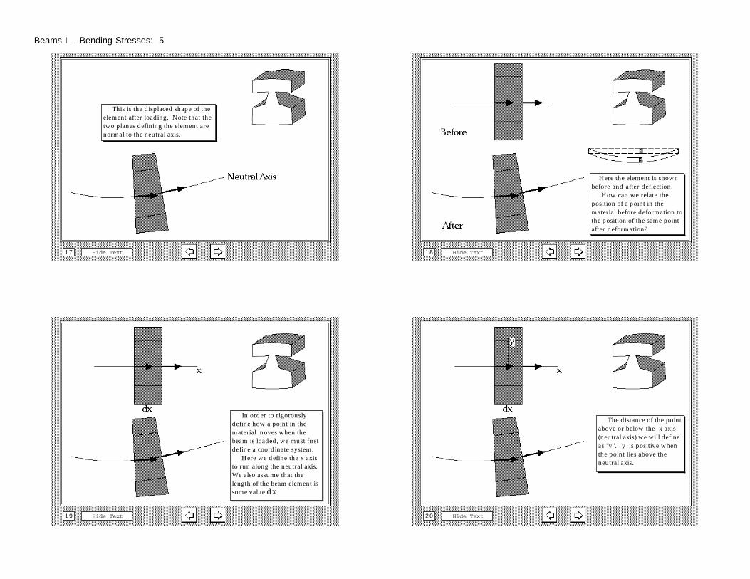
This is the displaced shape of the element after loading. Note that the two planes defining the element are normal to the neutral axis.
Hide Text1 8
Here the element is shown before and after deflection. How can we relate the position of a point in the material before deformation to the position of the same point after deformation?
Hide Text1 9
In order to rigorously define how a point in the material moves when the beam is loaded, we must first define a coordinate system. Here we define the x axis to run along the neutral axis. We also assume that the length of the beam element is some value dx.
Hide Text2 0
The distance of the point above or below the x axis (neutral axis) we will define as "y". y is positive when the point lies above the neutral axis.
Beams I -- Bending Stresses: 5
Hide Text2 1
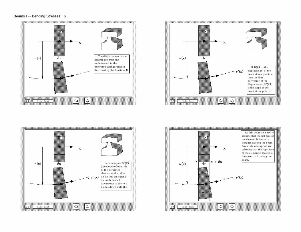
The displacement of the neutral axis from the undeformed to the deformed configuration is described by the function υ
Hide Text2 2
If υ(x) is the displacement of the beam at any point, x, then the first derivative of the displacement,υ'(x) , is the slope of the beam at the point x.
Hide Text2 3
Let's compare υ'(x) (the slope) of one side of the deformed element to the other. To do this we extend the undeformed orientation of the two planes down onto the
Hide Text2 4
At this point we need to assume that the left face of the element is located a distance x along the beam. From this assumption we calculate that the right face of the element is located a distance x + dx along the beam.
Beams I -- Bending Stresses: 6
Hide Text2 5
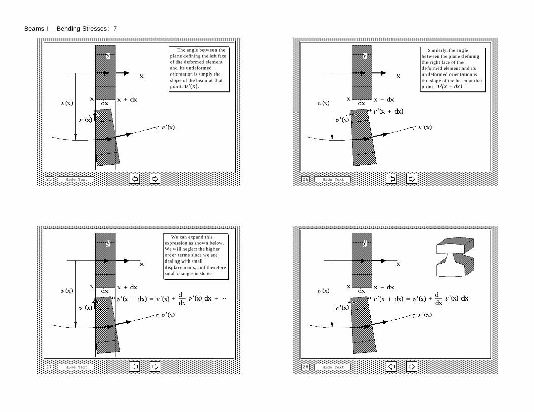
The angle between the plane defining the left face of the deformed element and its undeformed orientation is simply the slope of the beam at that point, υ '(x).
Hide Text2 6
Similarly, the angle between the plane defining the right face of the deformed element and its undeformed orientation is the slope of the beam at that point, υ'(x + dx) .
Hide Text2 7
We can expand this expression as shown below. We will neglect the higher order terms since we are dealing with small displacements, and therefore small changes in slopes.
Hide Text2 8
Beams I -- Bending Stresses: 7
Hide Text2 9
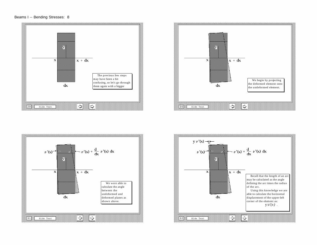
The previous few steps may have been a bit confusing, so let's go through them again with a bigger
Hide Text3 0
We begin by projecting the deformed element onto the undeformed element.
Hide Text3 1
We were able to calculate the angle between the undeformed and deformed planes as shown above.
Hide Text3 2
Recall that the length of an arc may be calculated as the angle defining the arc times the radius of the arc. Using this knowledge we are able to calculate the horizontal displacement of the upper-left corner of the element as: yυ'(x) .
Beams I -- Bending Stresses: 8
Hide Text3 3
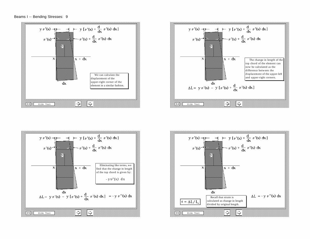
We can calculate the displacement of the upper-right corner of the element in a similar fashion.
Hide Text3 4
The change in length of the top chord of the element can now be calculated as the difference between the displacement of the upper-left and upper-right corners.
Hide Text3 5
Eliminating like terms, we find that the change in length of the top chord is given by: – yυ''(x) dx
Hide Text3 6
Recall that strain is calculated as change in length divided by original length.
Beams I -- Bending Stresses: 9
Hide Text3 7
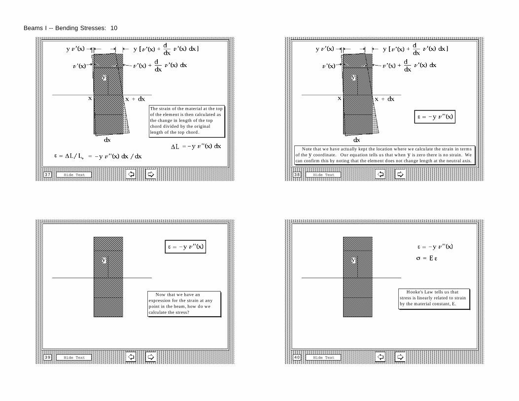
The strain of the material at the top of the element is then calculated as the change in length of the top chord divided by the original length of the top chord.
Hide Text3 8
Note that we have actually kept the location where we calculate the strain in terms of the y coordinate. Our equation tells us that when y is zero there is no strain. We can confirm this by noting that the element does not change length at the neutral axis.
Hide Text3 9
Now that we have an expression for the strain at any point in the beam, how do we calculate the stress?
Hide Text4 0
Hooke's Law tells us that stress is linearly related to strain by the material constant, E.
Beams I -- Bending Stresses: 10
Hide Text4 1
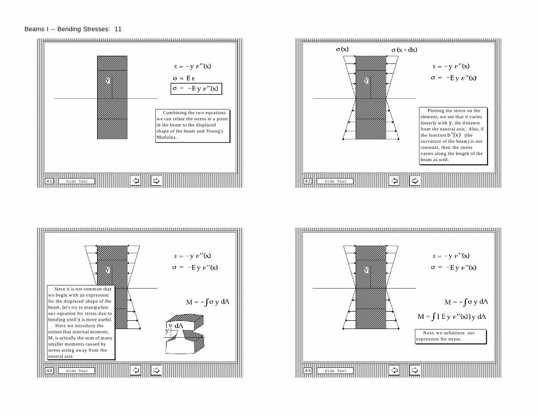
Combining the two equations we can relate the stress at a point in the beam to the displaced shape of the beam and Young's Modulus.
Hide Text4 2
Plotting the stress on the element, we see that it varies linearly with y, the distance from the neutral axis. Also, if the functionυ''(x) (the curvature of the beam) is not constant, then the stress varies along the length of the beam as well.
Hide Text4 3
Since it is not common that we begin with an expression for the displaced shape of the beam, let's try to manipulate our equation for stress due to bending until it is more useful. Here we introduce the notion that internal moment, M, is actually the sum of many smaller moments caused by stress acting away from the neutral axis.
Hide Text4 4
Next, we substitute our expression for stress.
Beams I -- Bending Stresses: 11
Hide Text4 5
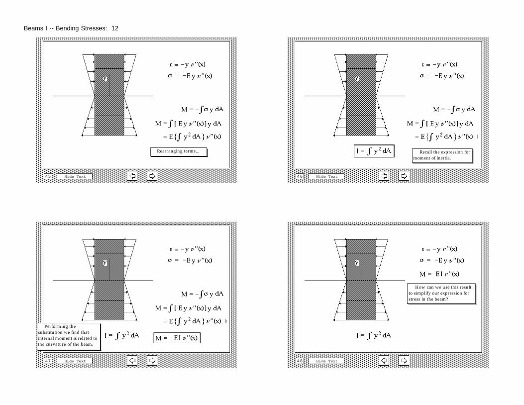
Rearranging terms...
Hide Text4 6
Recall the expression for moment of inertia.
Hide Text4 7
Performing the substitution we find that internal moment is related to the curvature of the beam.
Hide Text4 8
How can we use this result to simplify our expression for stress in the beam?
Beams I -- Bending Stresses: 12
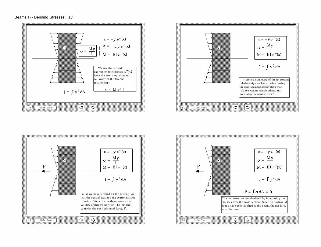
Hide Text4 9
We use the second expression to eliminate υ''(x) from the stress equation and we arrive at the famous relationship:
σ = –M y/ I
Hide Text5 0
Here is a summary of the important relationships we have derived using the displacement assumption that "plane sections remain plane, and normal to the neutral axis."
Hide Text5 1
So far we have worked on the assumption that the neutral axis and the centroidal axis coincide. We will now demonstrate the validity of this assumption. To this end, consider the net horizontal force, P.
Hide Text5 2
The net force can be calculated by integrating the stresses over the cross section. Since no horizontal loads have been applied to the beam, the net force must be zero.
Beams I -- Bending Stresses: 13
Hide Text5 3
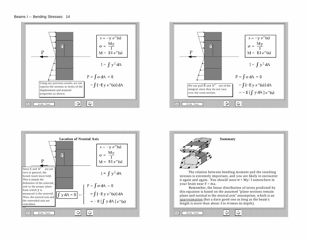
Using our previous results, we can express the stresses in terms of the displacement and material properties as shown.
Hide Text5 4
We can pull E and υ'' out of the integral, since they do not vary over the cross-section.
Location of Neutral Axis
Hide Text5 5
Since E and υ'' are not zero in general, the boxed result must hold. This is simply the definition of the centroid, and so the proper place from which y is measured is the centroid. Thus, the neutral axis and the centroidal axis are coincident.
Summary
Hide Text5 6
The relation between bending moment and the resulting stresses is extremely important, and you are likely to encounter it again and again. You should store σ = My/I somewhere in your brain near F = ma. Remember, the linear distribution of stress predicted by this equation is based on the assumed "plane sections remain plane and normal to the neutral axis" assumption, which is an approximation (but a darn good one as long as the beam's length is more than about 3 to 4 times its depth).
Beams I -- Bending Stresses: 14
End
Hide Text5 7
Beams I -- Bending Stresses: 15