Beamanal (Metric)
14
"BEAMANAL" --- SINGLE-SPAN and CONTINUOUS-SPAN BEAM ANALYSIS Program Description: "BEAMANAL" is a spreadsheet program written in MS-Excel for the purpose of analysis of eith continuous-span beams subjected to virtually any type of loading configuration. Four (4) t and two (2) through (5) span, continuous-span beams, considered. Specifically, beam end re maximum moments and deflections are calculated. Plots of both the shear and moment diagram as well as a tabulation of the shear, moment, slope, and deflection for the beam or each in Note: this is a metric units version of the original "BEAMANAL.xls" spreadsheet workbook. This program is a workbook consisting of three (3) worksheets, described as follows: Worksheet Name Description Doc This documentation sheet Single-Span Beam Single-span beam analysis for simple, propped, fixed, & cantil Continuous-Span Beam Continuous-span beam analysis for 2 through 5 span bea Program Assumptions and Limitations: 1. The following reference was used in the development of this program (see below): "Modern Formulas for Statics and Dynamics, A Stress-and-Strain Approach" by Walter D. Pilkey and Pin Yu Chang, McGraw-Hill Book Company (1978), pages 11 t 2. This program uses the three (3) following assumptions as a basis for analysis: a. Beams must be of constant cross section (E and I are constant for entire span b. Deflections must not significantly alter the geometry of the problem. c. Stress must remain within the "elastic" region. 3. On the beam or each individual span, this program will handle a full length uniform lo uniform, triangular, or trapezoidal loads, up to fifteen (15) point loads, and up to 4. For single-span beams, this program always assumes a particular orientation for two (2 different types. Specifically, the fixed end of either a "propped" or "cantilever" b the right end of the beam. 5. This program will calculate the beam end vertical reactions and moment reactions (if a the maximum positive moment and negative moment (if applicable), and the maximum nega and positive deflection (if applicable). The calculated values for the end reactions and deflections are determined from dividing the beam into fifty (50) equal segments and including all of the point load and applied moment locations as well. (Note: the moment occurs where the shear = 0, or passes through zero, while the actual point of where the slope = 0.) 6. The user is given the ability to input two (2) specific locations from the left end of shear, moment, slope, and deflection. 7. The user is also given the ability to select an AISC W, S, C, MC, or HSS (rectangular obtaining the X-axis moment of inertia for input for the purely analysis worksheets. 8. The plots of the shear and moment diagrams as well as the displayed tabulation of shea and deflection are based on the beam (or each individual span) being divided up into with fifty-one (51) points. 9. For continuous-span beam of from two (2) through five (5) spans, this program utilizes Equation Theory" and solves a system simultaneous equations to determine the support 10. This program contains numerous “comment boxes” which contain a wide variety of informa explanations of input or output items, equations used, data tables, etc. (Note: pre is denoted by a “red triangle” in the upper right-hand corner of a cell. Merely move desired cell to view the contents of that particular "comment box".)
Transcript of Beamanal (Metric)
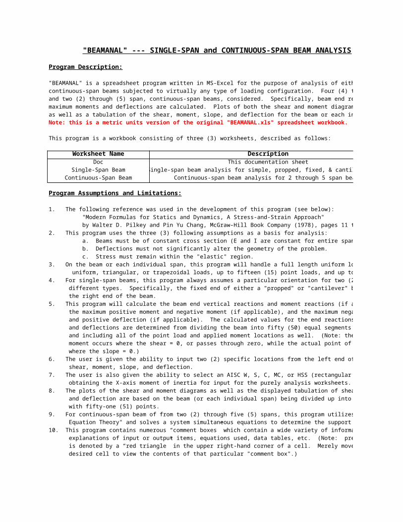
"BEAMANAL" --- SINGLE-SPAN and CONTINUOUS-SPAN BEAM ANALYSIS
Program Description:
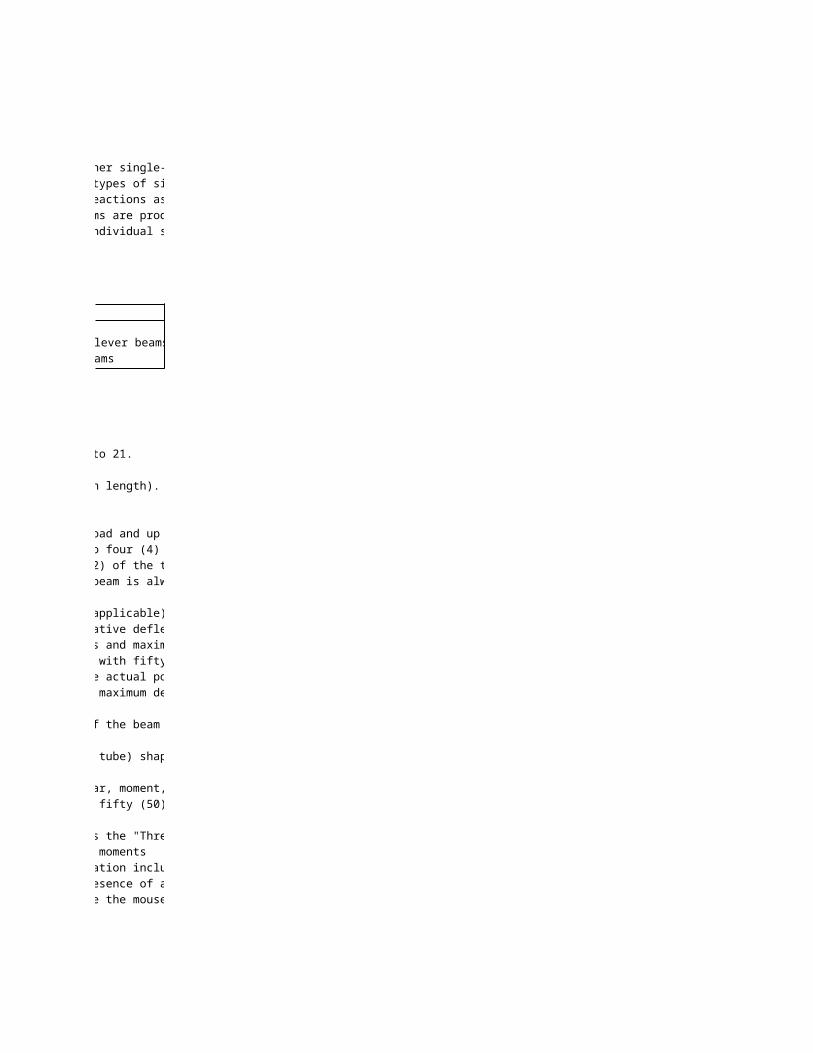
"BEAMANAL" is a spreadsheet program written in MS-Excel for the purpose of analysis of either single-span or
continuous-span beams subjected to virtually any type of loading configuration. Four (4) types of single-span beams
and two (2) through (5) span, continuous-span beams, considered. Specifically, beam end reactions as well as the
maximum moments and deflections are calculated. Plots of both the shear and moment diagrams are produced,
as well as a tabulation of the shear, moment, slope, and deflection for the beam or each individual span.
Note: this is a metric units version of the original "BEAMANAL.xls" spreadsheet workbook.
This program is a workbook consisting of three (3) worksheets, described as follows:
Worksheet Name DescriptionDoc This documentation sheet
Single-Span Beam Single-span beam analysis for simple, propped, fixed, & cantilever beams
Continuous-Span Beam Continuous-span beam analysis for 2 through 5 span beams
Program Assumptions and Limitations:
1. The following reference was used in the development of this program (see below):
"Modern Formulas for Statics and Dynamics, A Stress-and-Strain Approach"
by Walter D. Pilkey and Pin Yu Chang, McGraw-Hill Book Company (1978), pages 11 to 21.
2. This program uses the three (3) following assumptions as a basis for analysis:
a. Beams must be of constant cross section (E and I are constant for entire span length).
b. Deflections must not significantly alter the geometry of the problem.
c. Stress must remain within the "elastic" region.
3. On the beam or each individual span, this program will handle a full length uniform load and up to eight (8) partial
uniform, triangular, or trapezoidal loads, up to fifteen (15) point loads, and up to four (4) applied moments.
4. For single-span beams, this program always assumes a particular orientation for two (2) of the the four (4)
different types. Specifically, the fixed end of either a "propped" or "cantilever" beam is always assumed to be on
the right end of the beam.
5. This program will calculate the beam end vertical reactions and moment reactions (if applicable),
the maximum positive moment and negative moment (if applicable), and the maximum negative deflection
and positive deflection (if applicable). The calculated values for the end reactions and maximum moments
and deflections are determined from dividing the beam into fifty (50) equal segments with fifty-one (51) points,
and including all of the point load and applied moment locations as well. (Note: the actual point of maximum
moment occurs where the shear = 0, or passes through zero, while the actual point of maximum deflection is
where the slope = 0.)
6. The user is given the ability to input two (2) specific locations from the left end of the beam to calculate the
shear, moment, slope, and deflection.
7. The user is also given the ability to select an AISC W, S, C, MC, or HSS (rectangular tube) shape to aide in
obtaining the X-axis moment of inertia for input for the purely analysis worksheets.
8. The plots of the shear and moment diagrams as well as the displayed tabulation of shear, moment, slope,
and deflection are based on the beam (or each individual span) being divided up into fifty (50) equal segments
with fifty-one (51) points.
9. For continuous-span beam of from two (2) through five (5) spans, this program utilizes the "Three-Moment
Equation Theory" and solves a system simultaneous equations to determine the support moments
10. This program contains numerous “comment boxes” which contain a wide variety of information including
explanations of input or output items, equations used, data tables, etc. (Note: presence of a “comment box”
is denoted by a “red triangle” in the upper right-hand corner of a cell. Merely move the mouse pointer to the
desired cell to view the contents of that particular "comment box".)
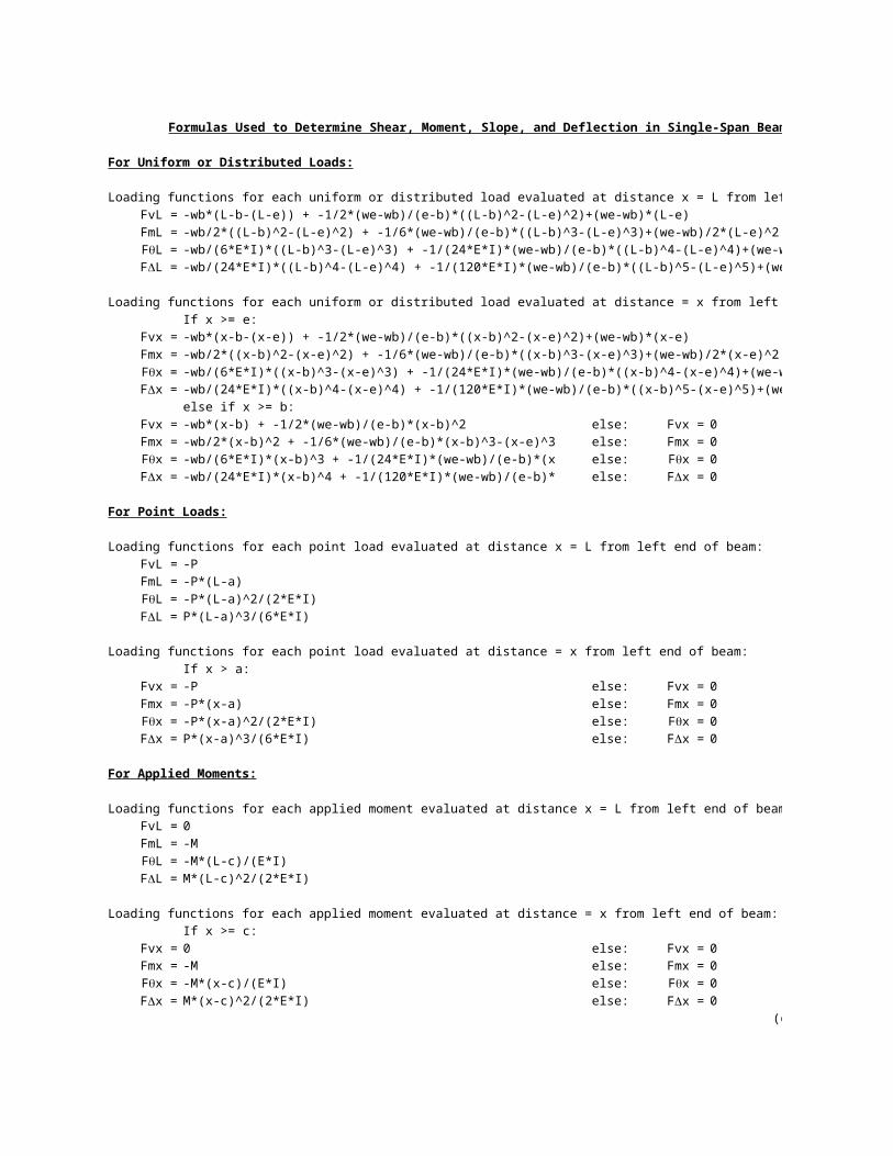
Formulas Used to Determine Shear, Moment, Slope, and Deflection in Single-Span Beams
For Uniform or Distributed Loads:
Loading functions for each uniform or distributed load evaluated at distance x = L from left end of beam:
FvL = -wb*(L-b-(L-e)) + -1/2*(we-wb)/(e-b)*((L-b)^2-(L-e)^2)+(we-wb)*(L-e)
FmL = -wb/2*((L-b)^2-(L-e)^2) + -1/6*(we-wb)/(e-b)*((L-b)^3-(L-e)^3)+(we-wb)/2*(L-e)^2
-wb/(6*E*I)*((L-b)^3-(L-e)^3) + -1/(24*E*I)*(we-wb)/(e-b)*((L-b)^4-(L-e)^4)+(we-wb)/(6*E*I)*(L-e)^3
-wb/(24*E*I)*((L-b)^4-(L-e)^4) + -1/(120*E*I)*(we-wb)/(e-b)*((L-b)^5-(L-e)^5)+(we-wb)/(24*E*I)*(L-e)^4
Loading functions for each uniform or distributed load evaluated at distance = x from left end of beam:
If x >= e:
Fvx = -wb*(x-b-(x-e)) + -1/2*(we-wb)/(e-b)*((x-b)^2-(x-e)^2)+(we-wb)*(x-e)
Fmx = -wb/2*((x-b)^2-(x-e)^2) + -1/6*(we-wb)/(e-b)*((x-b)^3-(x-e)^3)+(we-wb)/2*(x-e)^2
-wb/(6*E*I)*((x-b)^3-(x-e)^3) + -1/(24*E*I)*(we-wb)/(e-b)*((x-b)^4-(x-e)^4)+(we-wb)/(6*E*I)*(x-e)^3
-wb/(24*E*I)*((x-b)^4-(x-e)^4) + -1/(120*E*I)*(we-wb)/(e-b)*((x-b)^5-(x-e)^5)+(we-wb)/(24*E*I)*(x-e)^4
else if x >= b:
Fvx = -wb*(x-b) + -1/2*(we-wb)/(e-b)*(x-b)^2 else: Fvx = 0
Fmx = -wb/2*(x-b)^2 + -1/6*(we-wb)/(e-b)*(x-b)^3-(x-e)^3 else: Fmx = 0
-wb/(6*E*I)*(x-b)^3 + -1/(24*E*I)*(we-wb)/(e-b)*(x-b)^4 else: 0
-wb/(24*E*I)*(x-b)^4 + -1/(120*E*I)*(we-wb)/(e-b)*(x-b)^5 else: 0
For Point Loads:
Loading functions for each point load evaluated at distance x = L from left end of beam:
FvL = -P
FmL = -P*(L-a)
-P*(L-a)^2/(2*E*I)
P*(L-a)^3/(6*E*I)
Loading functions for each point load evaluated at distance = x from left end of beam:
If x > a:
Fvx = -P else: Fvx = 0
Fmx = -P*(x-a) else: Fmx = 0
-P*(x-a)^2/(2*E*I) else: 0
P*(x-a)^3/(6*E*I) else: 0
For Applied Moments:
Loading functions for each applied moment evaluated at distance x = L from left end of beam:
FvL = 0
FmL = -M
-M*(L-c)/(E*I)
M*(L-c)^2/(2*E*I)
Loading functions for each applied moment evaluated at distance = x from left end of beam:
If x >= c:
Fvx = 0 else: Fvx = 0
Fmx = -M else: Fmx = 0
-M*(x-c)/(E*I) else: 0
M*(x-c)^2/(2*E*I) else: 0
(continued)
FqL =
FDL =
Fqx =
FDx =
Fqx = Fqx =
FDx = FDx =
FqL =
FDL =
Fqx = Fqx =
FDx = FDx =
FqL =
FDL =
Fqx = Fqx =
FDx = FDx =
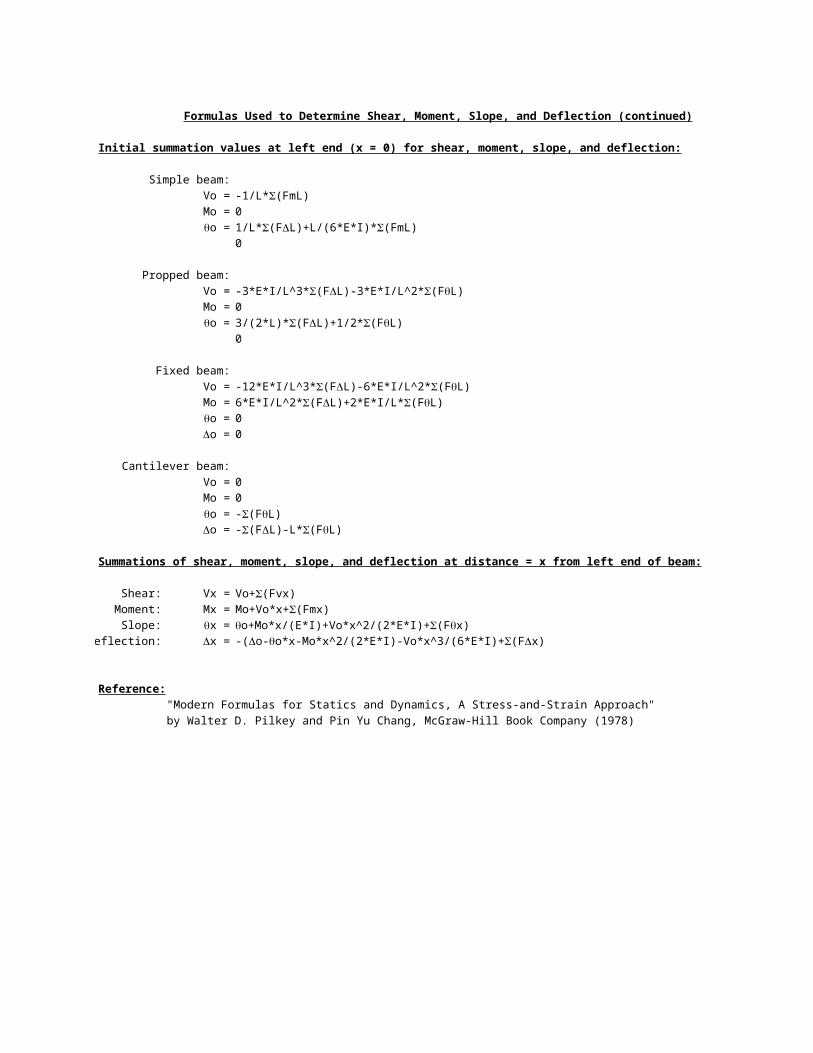
Formulas Used to Determine Shear, Moment, Slope, and Deflection (continued)
Initial summation values at left end (x = 0) for shear, moment, slope, and deflection:
Simple beam:
Vo =
Mo = 0
0
Propped beam:
Vo =
Mo = 0
0
Fixed beam:
Vo =
Mo =
0
0
Cantilever beam:
Vo = 0
Mo = 0
Summations of shear, moment, slope, and deflection at distance = x from left end of beam:
Shear: Vx =
Moment: Mx =
Slope:
Deflection:
Reference:
"Modern Formulas for Statics and Dynamics, A Stress-and-Strain Approach"
by Walter D. Pilkey and Pin Yu Chang, McGraw-Hill Book Company (1978)
-1/L*S(FmL)
qo = 1/L*S(FDL)+L/(6*E*I)*S(FmL)
Do =
-3*E*I/L^3*S(FDL)-3*E*I/L^2*S(FqL)
qo = 3/(2*L)*S(FDL)+1/2*S(FqL)
Do =
-12*E*I/L^3*S(FDL)-6*E*I/L^2*S(FqL)
6*E*I/L^2*S(FDL)+2*E*I/L*S(FqL)
qo =
Do =
qo = -S(FqL)
Do = -S(FDL)-L*S(FqL)
Vo+S(Fvx)
Mo+Vo*x+S(Fmx)
qx = qo+Mo*x/(E*I)+Vo*x^2/(2*E*I)+S(Fqx)
Dx = -(Do-qo*x-Mo*x^2/(2*E*I)-Vo*x^3/(6*E*I)+S(FDx)
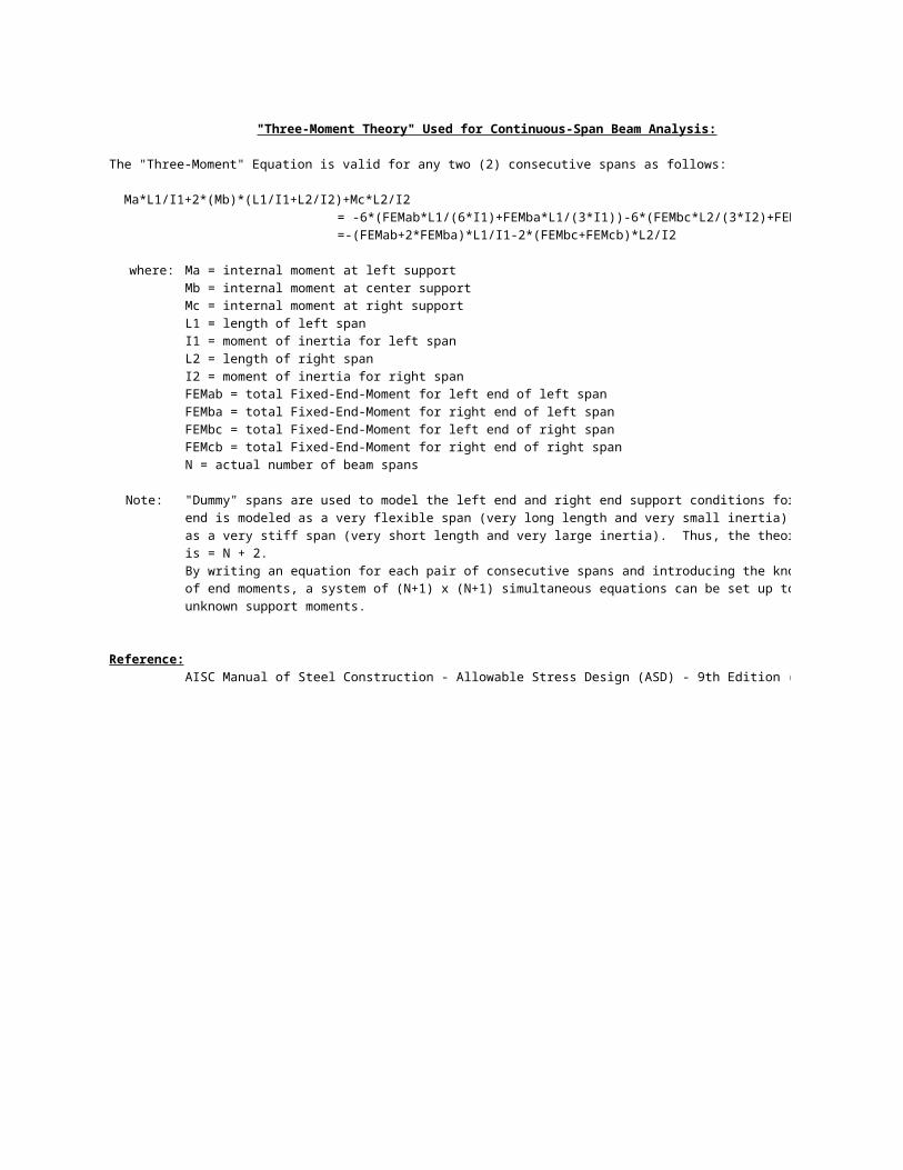
"Three-Moment Theory" Used for Continuous-Span Beam Analysis:
The "Three-Moment" Equation is valid for any two (2) consecutive spans as follows:
Ma*L1/I1+2*(Mb)*(L1/I1+L2/I2)+Mc*L2/I2
= -6*(FEMab*L1/(6*I1)+FEMba*L1/(3*I1))-6*(FEMbc*L2/(3*I2)+FEMcb*L2/(6*I2))
=-(FEMab+2*FEMba)*L1/I1-2*(FEMbc+FEMcb)*L2/I2
where: Ma = internal moment at left support
Mb = internal moment at center support
Mc = internal moment at right support
L1 = length of left span
I1 = moment of inertia for left span
L2 = length of right span
I2 = moment of inertia for right span
FEMab = total Fixed-End-Moment for left end of left span
FEMba = total Fixed-End-Moment for right end of left span
FEMbc = total Fixed-End-Moment for left end of right span
FEMcb = total Fixed-End-Moment for right end of right span
N = actual number of beam spans
Note: "Dummy" spans are used to model the left end and right end support conditions for the beam. A pinned
end is modeled as a very flexible span (very long length and very small inertia). A fixed end is modeled
as a very stiff span (very short length and very large inertia). Thus, the theoretical number of spans used
is = N + 2.
By writing an equation for each pair of consecutive spans and introducing the known values (usually zero)
of end moments, a system of (N+1) x (N+1) simultaneous equations can be set up to solve for the
unknown support moments.
Reference:
AISC Manual of Steel Construction - Allowable Stress Design (ASD) - 9th Edition (1989), page 2-294
"BEAMANAL.xls" Program(metric version)
Version 1.0
5 of 6 04/08/2023 15:17:18
SINGLE-SPAN BEAM ANALYSISFor Simple, Propped, Fixed, or Cantilever Beams
(Metric Units Version)Job Name: Subject: Loading Functions Evaluated at x = L
Job Number: Originator: Checker: Points:
###
Input Data: c ###
e ###
Beam Data: Simple Beam b ###
Span Type? Simple a ###
Span, L = 6.0000 m Propped Beam +P ###
Modulus, E = 200000 MPa ###
16274.65 cm^4 Fixed Beam +w ###
E,I L ###
Beam Loadings: Cantilever Beam x ###
Full Uniform: Nomenclature ###
w = 0.7300 kN/m ###
Start End Results: ###
Distributed:#1: 46.69 46.69 ###
#2: N.A. N.A. ###
#3:
#4: 136.79 3.000 ###
#5: 0.00 0.000 ###
#6:
#7: -12.683 3.000 ###
#8: 0.000 0.000 ###
L/473 ###
Point Loads: ###
#1: 3.0000 89.00 ###
#2: ###
#3: ###
#4: ###
#5: ###
#6: ###
#7: ###
#8: ###
#9: ###
#10: ###
#11: ###
#12: ###
#13: ###
#14: ###
#15: ###
###
Moments: ###
#1: ###
#2: ###
#3: ###
#4: ###
###
###
+M +we
+wbInertia, I =
RL RR
b (m) wb (kN/m) e (m) we (kN/m) Reactions (kN and kN-m):RL = RR =ML = MR =
Max. Moments (kN-m) and Locations (m):+M(max) = @ x =-M(max) = @ x =
Max. Deflections (mm) and Locations (m):-D(max) = @ x =+D(max) = @ x =D(ratio) =
a (m) P (kN)
c (m) M (kN-m)
0.00
0.12
0.24
0.36
0.48
0.60
0.72
0.84
0.96
1.08
1.20
1.32
1.44
1.56
1.68
1.80
1.92
2.04
2.16
2.28
2.40
2.52
2.64
2.76
2.88
3.00
3.12
3.24
3.36
3.48
3.60
3.72
3.84
3.96
4.08
4.20
4.32
4.44
4.56
4.68
4.80
4.92
5.04
5.16
5.28
5.40
5.52
5.64
5.76
5.88
6.00
-60.0
-40.0
-20.0
0.0
20.0
40.0
60.0Shear Diagram
x (m)
Sh
ea
r (k
N)
0.0
00.1
20.2
40.3
60.4
80.6
00.7
20.8
40.9
61.0
81.2
01.3
21.4
41.5
61.6
81.8
01.9
22.0
42.1
62.2
82.4
02.5
22.6
42.7
62.8
83.0
03.1
23.2
43.3
63.4
83.6
03.7
23.8
43.9
64.0
84.2
04.3
24.4
44.5
64.6
84.8
04.9
25.0
45.1
65.2
85.4
05.5
25.6
45.7
65.8
86.0
0
0.0
20.0
40.0
60.0
80.0
100.0
120.0
140.0
160.0 Moment Diagram
x (m)
Mo
me
nt
(kN
-m)
A16
The full uniformly distributed load, 'w', usually includes the self-weight of the beam.
A19
Up to 8 distributed loads may be input. These loads may be full or partial in length and may be varying in value (triangular or trapezoidal). Do not use "Space Bar" to clear contents of unused cells. "Highlight" those cells which are to be cleared and click on the Right Mouse Button and select "Clear Contents".
B19
'b' is the distance from the left end of the beam to the beginning (left side) of the distributed load. See Nomenclature illustration above.
C19
'wb' is the value of the distributed load at the beginning (left side) of the load. See Nomenclature illustration above.
D19
'e' is the distance from the left end of the beam to the end (right side) of the distributed load. See Nomenclature illustration above.
E19
'we' is the value of the distributed load at the end (right side) of the load. See Nomenclature illustration above.
G20
'RL' is the vertical reaction at left end of beam. Sign convention: positive (+) = upward. (Not applicable for cantilever beam.)
I20
'RR' is the vertical reaction at right end of beam. Sign convention: positive (+) = upward.
G21
'ML' is the moment reaction at left end of beam. Sign convention: positive (+) = clockwise (tension in bottom of beam). (Not applicable for simple, propped, and cantilever beams.)
I21
'MR' is the moment reaction at right end of beam. Sign convention: positive (+) = counterclockwise (tension in bottom of beam). (Not applicable for simple beam.)
G23
'+M(max)' is the maximum positive moment in beam. Positive (+) moment = tension in bottom of beam.
I23
'x' is the location of the maximum positive moment from left end of beam.
G24
'-M(max)' is the maximum negative moment in beam. Negative (-) moment = tension in top of beam.
I24
'x' is the location of the maximum negative moment from left end of beam.
G26
'-D(max)' is the maximum negative deflection in beam. Negative deflection is in downward direction.
I26
'x' is the location of the maximum negative deflection from left end of beam.
G27
'+D(max)' is the maximum positive deflection in beam. Positive deflection is in upward direction.
I27
'x' is the location of the maximum positive deflection from left end of beam.
G28
'D(ratio)' is the absolute maximum deflection ratio and is calculated as follows: D(ratio) = L/n where: n = L*1000/ABS(D(max))
A29
Up to 15 point (concentrated) loads may be input. Do not use "Space Bar" to clear contents of unused cells. "Highlight" those cells which are to be cleared and click on the Right Mouse Button and select "Clear Contents".
B29
'a' is the distance from the left end of the beam to the point load. See Nomenclature illustration above.
C29
The value of 'P' is positive (+) downward and negative (-) upward. See Nomenclature illustration above.
A46
Up to 4 externally applied moments may be input. Do not use "Space Bar" to clear contents of unused cells. "Highlight" those cells which are to be cleared and click on the Right Mouse Button and select "Clear Contents".
B46
'c' is the distance from the left end of the beam to the applied moment. See Nomenclature illustration above.
C46
The value of 'M' is positive (+) counterclockwise and negative (-) clockwise. See Nomenclature illustration above.
"BEAMANAL.xls" Program(metric version)
Version 1.0
6 of 6 04/08/2023 15:17:18
CONTINUOUS-SPAN BEAM ANALYSIS Summary of Results for Entire 2-Span Beam: CALCULATIONS:For Two (2) through Five (5) Span Beams Support Moments: Support Reactions:
(Metric Units Version) 0.00 kN-m 32.85 kN For Full Uniform Load, wJob Name: Subject: -65.70 kN-m 109.50 kNLoading Functions Evaluated at x = L
Job Number: Originator: Checker: 0.00 kN-m 32.85 kN ints:
c --- kN-m --- kN M(L):
Input Data: e --- kN-m --- kN (R):
b --- kN-m --- kN M(L):
Beam Data: a Maximum Moments in Beam: Span #2 FEM(R):
No. Spans, N = 2 +P +M 36.96 kN-m 2.250 m (Span #1) M(L):
Left End = Pinned Support #1 Span #1 Span #2 Span #3 Span #4 Span #5 -65.70 kN-m 6.000 m (Span #1) (R):
Right End = Pinned Support #3 +w Maximum Deflections in Beam: Span #4 FEM(L):
Modulus, E = 200000 MPa E,I L -3.148 mm 2.520 m (Span #1) (R):
Span and Support Nomenclature x 0.000 mm 0.000 m (Span #1) M(L):
Span Data and Loadings: L/1906 Span #5 FEM(R):
W44x248
Span Data: Span #1 Span #2 Span #3 Span #4 Span #5 M's6.0000 6.0000 ML:
16274.65 16274.65 MR:Full Uniform: Moment Matrix:
14.6000 14.6000 Dummy Spana1
Start End Start End Start End Start End Start End n/In:
Distributed: e (ft.) b1#1: 2*(Ln/In+L(n+1)/I(n+1))
#2: Load Vector:#3: b1R#4: MnL+2*MnR, 2*MnL+MnR:
#5: c1#6: ###
#7: W40x362
#8: For 2 Spans:
###
Point Loads: ###
#1: ###
#2: pans:
#3: ###
#4: ###
#5: ###
#6: 3x3 Matrix Inverse:#7: 1:
#8: 2:
#9: 3:
#10: 2:
#11: Results of 3x3 Solution (Support Moments):#12: M1 =
#13: M2 =
#14: M3 =
#15: M1 =
M2 =
Moments: M3 =
#1: M4 =
#2: M2 =
#3: M3 =
#4: M4 =
M5 =
Left End Cantilever Shear = 0.00 kN Left End Cantilever Moment = 0.00 kN-m Right End Cantilever Shear = 0.00 kN Right End Cantilever Moment = 0.00 kN-m M3 =
Results: M4 =
32.85 -54.75 54.75 -32.85 --- --- --- --- --- --- M5 =
M6 =
M1 = R1 =M2 = R2 =M3 = R3 =M4 = R4 =M5 = R5 =M6 = R6 =
+we +M(max) = @ x =
+wb -M(max) = @ x =
-D(max) = @ x = VL VR +D(max) = @ x =
Load Nomenclature D(ratio) =
Span, L (m) =Inertia, I (cm^4) =
w (kN/m) =
b (m) wb (kN/m) e (m) we (kN/m) b (m) wb (kN/m) e (m) we (kN/m) b (m) wb (kN/m) we (kN/m) b (m) wb (kN/m) e (m) we (kN/m) b (m) wb (kN/m) e (m) we (kN/m)
a (m) P (kN) a (m) P (kN) a (m) P (kN) a (m) P (kN) a (m) P (kN)
c (m) M (kN-m) c (m) M (kN-m) c (m) M (kN-m) c (m) M (kN-m) c (m) M (kN-m)
End Shears (kN):
1 222
3 4 5 6
Q10
'+M(max)' is the maximum positive moment in beam. Positive (+) moment = tension in bottom of beam.
T10
'x' is the location of the maximum positive moment from left end of beam.
Q11
'-M(max)' is the maximum negative moment in beam. Negative (-) moment = tension in top of beam.
T11
'x' is the location of the maximum negative moment from left end of beam.
Q13
'-D(max)' is the maximum negative deflection in beam. Negative deflection is in downward direction.
T13
'x' is the location of the maximum negative deflection from left end of beam.
Q14
'+D(max)' is the maximum positive deflection in beam. Positive deflection is in upward direction.
T14
'x' is the location of the maximum positive deflection from left end of beam.
Q15
'D(ratio)' is the absolute maximum deflection ratio and is calculated as follows: D(ratio) = L/n where: n = L*1000/ABS(D(max))
A17
Do not use "Space Bar" to clear contents of unused cells. "Highlight" those cells which are to be cleared and click on the Right Mouse Button and select "Clear Contents".
A20
The full uniformly distributed load (kips/ft.), 'w', usually includes the self-weight of the beam for each span.
A24
Up to 8 distributed loads per span may be input. These loads may be full or partial in length and may be varying in value (triangular or trapezoidal). Do not use "Space Bar" to clear contents of unused cells. "Highlight" those cells which are to be cleared and click on the Right Mouse Button and select "Clear Contents".
B24
'b' is the distance from the left end of beam span #1 to the beginning (left side) of the distributed load. See Nomenclature illustration above.
C24
'wb' is the value of the distributed load at the beginning (left side) of the load. See Nomenclature illustration above.
D24
'e' is the distance from the left end of beam span #1 to the end (right side) of the distributed load. See Nomenclature illustration above.
E24
'we' is the value of the distributed load at the end (right side) of the load. See Nomenclature illustration above.
F24
'b' is the distance from the left end of beam span #2 to the beginning (left side) of the distributed load. See Nomenclature illustration above.
G24
'wb' is the value of the distributed load at the beginning (left side) of the load. See Nomenclature illustration above.
H24
'e' is the distance from the left end of beam span #2 to the end (right side) of the distributed load. See Nomenclature illustration above.
I24
'we' is the value of the distributed load at the end (right side) of the load. See Nomenclature illustration above.
J24
'b' is the distance from the left end of beam span #3 to the beginning (left side) of the distributed load. See Nomenclature illustration above.
K24
'wb' is the value of the distributed load at the beginning (left side) of the load. See Nomenclature illustration above.
L24
'e' is the distance from the left end of beam span #3 to the end (right side) of the distributed load. See Nomenclature illustration above.
M24
'we' is the value of the distributed load at the end (right side) of the load. See Nomenclature illustration above.
N24
'b' is the distance from the left end of beam span #4 to the beginning (left side) of the distributed load. See Nomenclature illustration above.
O24
'wb' is the value of the distributed load at the beginning (left side) of the load. See Nomenclature illustration above.
P24
'e' is the distance from the left end of beam span #4 to the end (right side) of the distributed load. See Nomenclature illustration above.
Q24
'we' is the value of the distributed load at the end (right side) of the load. See Nomenclature illustration above.
R24
'b' is the distance from the left end of beam span #5 to the beginning (left side) of the distributed load. See Nomenclature illustration above.
S24
'wb' is the value of the distributed load at the beginning (left side) of the load. See Nomenclature illustration above.
T24
'e' is the distance from the left end of beam span #5 to the end (right side) of the distributed load. See Nomenclature illustration above.
U24
'we' is the value of the distributed load at the end (right side) of the load. See Nomenclature illustration above.
A34
Up to 15 point (concentrated) loads per span may be input. Do not use "Space Bar" to clear contents of unused cells. "Highlight" those cells which are to be cleared and click on the Right Mouse Button and select "Clear Contents".
B34
'a' is the distance from the left end of beam span #1 to the point load. See Nomenclature illustration above.
D34
See Nomenclature illustration above.
F34
'a' is the distance from the left end of beam span #2 to the point load. See Nomenclature illustration above.
H34
The value of 'P' is positive (+) downward and negative (-) upward. See Nomenclature illustration above.
J34
'a' is the distance from the left end of beam span #3 to the point load. See Nomenclature illustration above.
L34
The value of 'P' is positive (+) downward and negative (-) upward. See Nomenclature illustration above.
N34
'a' is the distance from the left end of beam span #4 to the point load. See Nomenclature illustration above.
P34
The value of 'P' is positive (+) downward and negative (-) upward. See Nomenclature illustration above.
R34
'a' is the distance from the left end of beam span #5 to the point load. See Nomenclature illustration above.
T34
The value of 'P' is positive (+) downward and negative (-) upward. See Nomenclature illustration above.
A51
Up to 4 externally applied moments may be input. Do not use "Space Bar" to clear contents of unused cells. "Highlight" those cells which are to be cleared and click on the Right Mouse Button and select "Clear Contents".
B51
'c' is the distance from the left end of beam span #1 to the applied moment. See Nomenclature illustration above.
D51
The value of 'M' is positive (+) counterclockwise and negative (-) clockwise. See Nomenclature illustration above.
F51
'c' is the distance from the left end of beam span #2 to the applied moment. See Nomenclature illustration above.
H51
The value of 'M' is positive (+) counterclockwise and negative (-) clockwise. See Nomenclature illustration above.
J51
'c' is the distance from the left end of beam span #3 to the applied moment. See Nomenclature illustration above.
L51
The value of 'M' is positive (+) counterclockwise and negative (-) clockwise. See Nomenclature illustration above.
N51
'c' is the distance from the left end of beam span #4 to the applied moment. See Nomenclature illustration above.
P51
The value of 'M' is positive (+) counterclockwise and negative (-) clockwise. See Nomenclature illustration above.
R51
'c' is the distance from the left end of beam span #5 to the applied moment. See Nomenclature illustration above.
T51
The value of 'M' is positive (+) counterclockwise and negative (-) clockwise. See Nomenclature illustration above.
C57
For a beam with a cantilever at left end, input the total shear resulting from the loads on the cantilever portion. The value is positive (+) downward and negative (-) upward.
H57
For a beam with a cantilever at left end, input the total moment resulting from the loads on the cantilever portion. The value is positive (+) counterclockwise and negative (-) clockwise.
N57
For a beam with a cantilever at right end, input the total shear resulting from the loads on the cantilever portion. The value is positive (+) downward and negative (-) upward.
S57
For a beam with a cantilever at right end, input the total moment resulting from the loads on the cantilever portion. The value is positive (+) counterclockwise and negative (-) clockwise.